University of Nebraska - Lincoln University of Nebraska - Lincoln DigitalCommons@University of Nebraska - Lincoln DigitalCommons@University of Nebraska - Lincoln Computer Science and Engineering: Theses, Dissertations, and Student Research Computer Science and Engineering, Department of Fall 12-4-2019 Advanced Security Analysis for Emergent Software Platforms Advanced Security Analysis for Emergent Software Platforms Mohannad Alhanahnah University of Nebraska - Lincoln, [email protected] Follow this and additional works at: https://digitalcommons.unl.edu/computerscidiss Part of the Computer Engineering Commons, Information Security Commons, and the Software Engineering Commons Alhanahnah, Mohannad, "Advanced Security Analysis for Emergent Software Platforms" (2019). Computer Science and Engineering: Theses, Dissertations, and Student Research. 182. https://digitalcommons.unl.edu/computerscidiss/182 This Article is brought to you for free and open access by the Computer Science and Engineering, Department of at DigitalCommons@University of Nebraska - Lincoln. It has been accepted for inclusion in Computer Science and Engineering: Theses, Dissertations, and Student Research by an authorized administrator of DigitalCommons@University of Nebraska - Lincoln.

Welcome message from author
This document is posted to help you gain knowledge. Please leave a comment to let me know what you think about it! Share it to your friends and learn new things together.
Transcript
University of Nebraska - Lincoln University of Nebraska - Lincoln
DigitalCommons@University of Nebraska - Lincoln DigitalCommons@University of Nebraska - Lincoln
Computer Science and Engineering: Theses, Dissertations, and Student Research
Computer Science and Engineering, Department of
Fall 12-4-2019
Advanced Security Analysis for Emergent Software Platforms Advanced Security Analysis for Emergent Software Platforms
Mohannad Alhanahnah University of Nebraska - Lincoln, [email protected]
Follow this and additional works at: https://digitalcommons.unl.edu/computerscidiss
Part of the Computer Engineering Commons, Information Security Commons, and the Software
Engineering Commons
Alhanahnah, Mohannad, "Advanced Security Analysis for Emergent Software Platforms" (2019). Computer Science and Engineering: Theses, Dissertations, and Student Research. 182. https://digitalcommons.unl.edu/computerscidiss/182
This Article is brought to you for free and open access by the Computer Science and Engineering, Department of at DigitalCommons@University of Nebraska - Lincoln. It has been accepted for inclusion in Computer Science and Engineering: Theses, Dissertations, and Student Research by an authorized administrator of DigitalCommons@University of Nebraska - Lincoln.

ADVANCED SECURITY ANALYSIS FOR EMERGENT SOFTWARE PLATFORMS
by
Mohannad Alhanahnah
A DISSERTATION
Presented to the Faculty of
The Graduate College at the University of Nebraska
In Partial Fulfillment of Requirements
For the Degree of Doctor of Philosophy
Major: Engineering
(Computer Engineering-Computer Science)
Under the Supervision of Professors Hamid Bagheri and Qiben Yan
Lincoln, Nebraska
December, 2019

ADVANCED SECURITY ANALYSIS FOR EMERGENT SOFTWARE PLATFORMS
Mohannad Alhanahnah, Ph. D.
University of Nebraska, 2019
Advisers: Hamid Bagheri and Qiben Yan
Emergent software ecosystems, boomed by the advent of smartphones and the
Internet of Things (IoT) platforms, are perpetually sophisticated, deployed into
highly dynamic environments, and facilitating interactions across heterogeneous
domains. Accordingly, assessing the security thereof is a pressing need, yet requires
high levels of scalability and reliability to handle the dynamism involved in such
volatile ecosystems.
This dissertation seeks to enhance conventional security detection methods
to cope with the emergent features of contemporary software ecosystems. In
particular, it analyzes the security of Android and IoT ecosystems by developing
rigorous vulnerability detection methods. A critical aspect of this work is the
focus on detecting vulnerable and unsafe interactions between applications that
share common components and devices. Contributions of this work include novel
insights and methods for: (1) detecting vulnerable interactions between Android
applications that leverage dynamic loading features for concealing the interactions;
(2) identifying unsafe interactions between smart home applications by considering
physical and cyber channels; (3) detecting malicious IoT applications that are
developed to target numerous IoT devices; (4) detecting insecure patterns of
emergent security APIs that are reused from open-source software. In all of
the four research thrusts, we present thorough security analysis and extensive
evaluations based on real-world applications. Our results demonstrate that the

proposed detection mechanisms can efficiently and effectively detect vulnerabilities
in contemporary software platforms.

iv
DEDICATION
To my parents Jamal Alhanahnah and Salha Alnajdawi,
my in-laws Raid and Evelyn Elhamawi,
and my beloved wife Zeineh Elhamawi.

v
ACKNOWLEDGMENTS
I am exceedingly thankful to my advisers, Dr. Qiben Yan and Dr. Hamid Bagheri
who encouraged me to wok on cutting edge problems, which allowed me to have
a unique combination between cybersecurity and software engineering. Indeed,
no words can ever fully express my gratitude for their invaluable guidance and
amazing mentorship.
Special thanks to my supervisory committee, Professors Witawas Srisa-an,
ThanhVu Nguyen and Hamid Sharif for their support, guidance and helpful
suggestions. I am especially thankful to Dr. Witawas Srisa-an for his unlimited
support at all stages of my journey. I indeed enjoyed all of my discussions with
him. I am also very grateful to Dr. ThanhVu Nguyen for sharing his expertise
in the Software Verification class, and appreciate his support to attend the Ninth
Summer School on Formal Techniques.
I thank my colleagues at THINK and ESQuaReD labs, especially Clay Stevens,
Niloofar Mansoor, Bruno Silva, Nikolay Ivanov, Qicheng Lin, Qi Xia and Boyang
Hu, who made my graduate studies a wonderful academic experience. I am
thankful to my friends and colleagues at the CSE department, Najeeb Najeeb,
Abdul Salam, Sara El Alaoui, Zahmeeth Sakkaff, and Jared Soundy. I am also
grateful to my Jordanian friends in Lincoln, Mohammad Alhowaidi, Mohammad
Bawaneh and Mahmoud Masa’deh and his family who made me feel comfortable
in a place that is new to me.
I would like to express my immense gratitude to my parents, siblings and my
wife for their encouragement and patience throughout this journey.
I’m deeply and humbly grateful to Allah for being able to complete this
dissertation. I would like to thank Allah Almighty who enabled me to research this

vi
topic. It was God’s power and blessing that enabled me to get through this fruitful
experience. I ask God for good deeds that are accepted, for beneficial knowledge,
kindness, success, and inspiration throughout the duration of completing my Ph.D.
vii
Table of Contents
List of Figures xi
List of Tables xiv
1 Introduction 1
1.1 Emergent Software Platforms . . . . . . . . . . . . . . . . . . . . . . . 1
1.2 Security Challenges in Emergent Platforms . . . . . . . . . . . . . . . 3
1.2.1 Feature Interaction (FI) . . . . . . . . . . . . . . . . . . . . . . . 3
1.2.2 Cross-Architecture Malware . . . . . . . . . . . . . . . . . . . . 7
1.2.3 Code Reuse . . . . . . . . . . . . . . . . . . . . . . . . . . . . . 8
1.3 Research Contributions . . . . . . . . . . . . . . . . . . . . . . . . . . . 9
1.4 Organization . . . . . . . . . . . . . . . . . . . . . . . . . . . . . . . . . 11
2 Related Work 12
2.1 Android Inter-app Communication . . . . . . . . . . . . . . . . . . . . 12
2.2 Smart home safety and security . . . . . . . . . . . . . . . . . . . . . . 14
2.3 IoT Malware Detection . . . . . . . . . . . . . . . . . . . . . . . . . . . 15
2.4 Insecure SSL/TLS implementation Detection . . . . . . . . . . . . . . 17
3 Dina: Detecting Hidden Android Inter-App Communication in Dy-
namic Loaded Code 18
viii
3.1 Background and Challenges . . . . . . . . . . . . . . . . . . . . . . . . 19
3.2 Motivating Example . . . . . . . . . . . . . . . . . . . . . . . . . . . . 21
3.3 Threat Model . . . . . . . . . . . . . . . . . . . . . . . . . . . . . . . . 25
3.4 DINA System Design . . . . . . . . . . . . . . . . . . . . . . . . . . . . 26
3.4.1 Collective Static Analysis . . . . . . . . . . . . . . . . . . . . . 26
3.4.2 Incremental Dynamic Analysis . . . . . . . . . . . . . . . . . . 28
3.4.3 Path Construction . . . . . . . . . . . . . . . . . . . . . . . . . . 29
3.4.4 IAC Vulnerability Analysis . . . . . . . . . . . . . . . . . . . . 31
3.5 DINA Implementation . . . . . . . . . . . . . . . . . . . . . . . . . . . 33
3.5.1 Class Loading Implementation . . . . . . . . . . . . . . . . . . 34
3.5.2 IAC Analyzer Implementation . . . . . . . . . . . . . . . . . . 34
3.5.3 Dynamic Analyzer Implementation . . . . . . . . . . . . . . . 35
3.6 Evaluation . . . . . . . . . . . . . . . . . . . . . . . . . . . . . . . . . . 37
3.6.1 How accurate is Dina? . . . . . . . . . . . . . . . . . . . . . . . 37
3.6.2 How robust is Dina? . . . . . . . . . . . . . . . . . . . . . . . . 41
3.6.3 How effective is Dina? . . . . . . . . . . . . . . . . . . . . . . . 43
3.6.4 How efficient is Dina? . . . . . . . . . . . . . . . . . . . . . . . 47
3.7 Discussion . . . . . . . . . . . . . . . . . . . . . . . . . . . . . . . . . . 49
3.8 Summary . . . . . . . . . . . . . . . . . . . . . . . . . . . . . . . . . . . 50
4 IotCom: Compositional Safety and Security Analysis of IoT Systems 52
4.1 Background . . . . . . . . . . . . . . . . . . . . . . . . . . . . . . . . . 53
4.2 Illustrative Example . . . . . . . . . . . . . . . . . . . . . . . . . . . . . 55
4.3 Safety Goals for IoT App Interactions . . . . . . . . . . . . . . . . . . 56
4.4 Approach Overview . . . . . . . . . . . . . . . . . . . . . . . . . . . . 58
4.5 Behavioral Rule Extractor . . . . . . . . . . . . . . . . . . . . . . . . . 59

ix
4.5.1 Building ICFG . . . . . . . . . . . . . . . . . . . . . . . . . . . . 60
4.5.2 Generating Behavioral Rule Graph . . . . . . . . . . . . . . . . 64
4.5.3 Generating Rule Models . . . . . . . . . . . . . . . . . . . . . . 66
4.6 Formal Analyzer . . . . . . . . . . . . . . . . . . . . . . . . . . . . . . 68
4.6.1 Smart Home Model . . . . . . . . . . . . . . . . . . . . . . . . . 68
4.6.2 Extracted Behavioral Rule Models . . . . . . . . . . . . . . . . 70
4.6.3 Safety/Security Properties . . . . . . . . . . . . . . . . . . . . . 71
4.7 Evaluation . . . . . . . . . . . . . . . . . . . . . . . . . . . . . . . . . . 73
4.7.1 Results for RQ1 (Accuracy) . . . . . . . . . . . . . . . . . . . . 74
4.7.2 Results for RQ2 (IotCom and Real-World Apps) . . . . . . . . 77
4.7.3 Results for RQ3 (Performance and Timing) . . . . . . . . . . . 81
4.8 Discussion . . . . . . . . . . . . . . . . . . . . . . . . . . . . . . . . . . 84
4.9 Summary . . . . . . . . . . . . . . . . . . . . . . . . . . . . . . . . . . . 85
5 Efficient Signature Generation for Classifying Cross-Architecture IoT
Malware 86
5.1 Motivation . . . . . . . . . . . . . . . . . . . . . . . . . . . . . . . . . . 87
5.2 Signature Generation of IoT Malware . . . . . . . . . . . . . . . . . . 90
5.2.1 System Overview . . . . . . . . . . . . . . . . . . . . . . . . . . 91
5.2.2 Clustering IoT Malware . . . . . . . . . . . . . . . . . . . . . . 91
5.2.3 Cluster Merging . . . . . . . . . . . . . . . . . . . . . . . . . . . 95
5.2.4 Signature Generation and Online Detection/Classification . . 97
5.3 Evaluation . . . . . . . . . . . . . . . . . . . . . . . . . . . . . . . . . . 99
5.3.1 Selecting Parameters K and N . . . . . . . . . . . . . . . . . . 100
5.3.2 Evaluating Malware Clustering . . . . . . . . . . . . . . . . . . 102
5.3.3 Evaluating Signature Detection . . . . . . . . . . . . . . . . . . 104

x
5.3.4 Evaluating Runtime Performance . . . . . . . . . . . . . . . . . 106
5.4 Discussion . . . . . . . . . . . . . . . . . . . . . . . . . . . . . . . . . . 106
5.5 Summary . . . . . . . . . . . . . . . . . . . . . . . . . . . . . . . . . . . 107
6 Towards Best Secure Coding Practice for Implementing SSL/TLS 109
6.1 Background . . . . . . . . . . . . . . . . . . . . . . . . . . . . . . . . . 110
6.2 Insecure SSL/TLS Patterns . . . . . . . . . . . . . . . . . . . . . . . . . 112
6.3 Proposed PMD Rulesets . . . . . . . . . . . . . . . . . . . . . . . . . . 114
6.3.1 PMD Rulesets and Rules . . . . . . . . . . . . . . . . . . . . . . 114
6.4 Evaluation . . . . . . . . . . . . . . . . . . . . . . . . . . . . . . . . . . 120
6.4.1 Results for RQ1 . . . . . . . . . . . . . . . . . . . . . . . . . . . 121
6.4.2 Results for RQ2 . . . . . . . . . . . . . . . . . . . . . . . . . . . 123
6.5 Discussions . . . . . . . . . . . . . . . . . . . . . . . . . . . . . . . . . . 123
6.6 Summary . . . . . . . . . . . . . . . . . . . . . . . . . . . . . . . . . . . 124
7 Conclusion and Future Research 126
7.1 Research Summary . . . . . . . . . . . . . . . . . . . . . . . . . . . . . 126
7.2 Future Research Directions . . . . . . . . . . . . . . . . . . . . . . . . 128
7.2.1 Cross-platforms interactions . . . . . . . . . . . . . . . . . . . . 129
7.2.2 Smelling the Vulnerability in Open Source Android Applica-
tions . . . . . . . . . . . . . . . . . . . . . . . . . . . . . . . . . 130
7.2.3 Feature Interaction in Robotics Ecosystem . . . . . . . . . . . 133
7.2.4 Enforcement of Safe Interactions . . . . . . . . . . . . . . . . . 135
Bibliography 136

xi
List of Figures
1.1 Dissertation Road-map . . . . . . . . . . . . . . . . . . . . . . . . . . . . . 3
3.1 A typical reflective call used to defeat static analyzers. . . . . . . . . . . 20
3.2 Malicious app downloads code at runtime, and then uses it for leaking
sensitive information. . . . . . . . . . . . . . . . . . . . . . . . . . . . . . . 21
3.3 Architecture of DINA . . . . . . . . . . . . . . . . . . . . . . . . . . . . . . 27
3.4 A simplified sensitive path example: the dashed method and paths can
be captured during DINA’s dynamic analysis phase. . . . . . . . . . . . 32
3.5 Instruction Graph for the method onCreate (Listing 3.5) that includes
both control-flow and data-flow. . . . . . . . . . . . . . . . . . . . . . . . 36
3.6 (a). Activity 1 of sender app; (b). Activity 2 of sender app initiated
through reflection; (c). Activity 3 represents the activity of receiver app
invoked by IAC; (d). Inject malicious email address in the sender app
to launch attack via IAC. . . . . . . . . . . . . . . . . . . . . . . . . . . . . 44
3.7 (a). Activity 1 of sender app; (b). Activity 2 of sender app initiated
through reflection; (c). Activity 3 represents the activity of receiver app
invoked by IAC; (d). Captured log confirms the IAC. . . . . . . . . . . . 47
3.8 Static analysis time. . . . . . . . . . . . . . . . . . . . . . . . . . . . . . . . 48
3.9 Dynamic analysis time. . . . . . . . . . . . . . . . . . . . . . . . . . . . . . 48
xii
3.10 Runtime performance comparison. . . . . . . . . . . . . . . . . . . . . . . 49
4.1 Smart Home Automation Model. . . . . . . . . . . . . . . . . . . . . . . 53
4.2 An example of malicious IoT apps interaction. . . . . . . . . . . . . . . . 56
4.3 IotCom System Overview. . . . . . . . . . . . . . . . . . . . . . . . . . . 59
4.4 Extracted models for MaliciousApp, described in Listing 1, at different
steps of analysis. . . . . . . . . . . . . . . . . . . . . . . . . . . . . . . . . 64
4.5 Counterexample from Alloy for running example. . . . . . . . . . . . . . 71
4.6 Example violation of G1 (No unintended behavior): Lights continually
turn off and on. The violation occurs via the luminance physical channel. 78
4.7 Example violation of (G2) No unpredictable behavior: Both “on” and “off”
commands sent to the same light due to the same event. The violation
happens via the luminance physical channel. . . . . . . . . . . . . . . . . 79
4.8 Example violation of (G3) No unsafe behavior: Cyber coordination be-
tween apps may leave the door unlocked when no one is home. The
first rule is guarded by a condition that the home owner not be present. 80
4.9 Distribution of detection violations across three goals (cf. Section 4.3). . 81
4.10 Scatter plot representing analysis time for behavioral rule extraction of
IoT apps using IotCom. . . . . . . . . . . . . . . . . . . . . . . . . . . . . 82
4.11 Average time required to analyze all properties related to each goal by
number of rules in the analyzed bundle. . . . . . . . . . . . . . . . . . . . 82
4.12 Verification time by IotCom and IoTSAN to perform the same safety
violation detection in a logarithmic scale. . . . . . . . . . . . . . . . . . . 83
5.1 IoT malware distribution based on CPU types . . . . . . . . . . . . . . . 89
5.2 Detection system architecture . . . . . . . . . . . . . . . . . . . . . . . . . 90
5.3 String feature analysis (S1,· · · , Sn are n samples in a cluster) . . . . . . . 96

xiii
5.4 Inter-cluster and Intra-cluster string similarity with different K values
(N = 4) . . . . . . . . . . . . . . . . . . . . . . . . . . . . . . . . . . . . . . 101
5.5 DaviesâASBouldin index for evaluating the number of coarse-grained
clusters . . . . . . . . . . . . . . . . . . . . . . . . . . . . . . . . . . . . . . 102
5.6 Distribution of cluster cohesion . . . . . . . . . . . . . . . . . . . . . . . . 104
6.1 Insecure SSL/TLS implementation patterns . . . . . . . . . . . . . . . . . 112
6.2 PMD architecture and the proposed PMD rulesets (SSL_Vuln_Ruleset) . 115
6.3 PMD ruleset structure . . . . . . . . . . . . . . . . . . . . . . . . . . . . . 115
6.4 PMD analysis results on Eclipse after adding a new rule . . . . . . . . . 118
6.5 Distribution of vulnerability detection using proposed PMD rulesets . . 121
6.6 Detection results according to the types of SSL/TLS Vulnerabilities . . . 122
7.1 Analysis Workflow. . . . . . . . . . . . . . . . . . . . . . . . . . . . . . . . 132

xiv
List of Tables
3.1 A non-exhaustive list of Intent APIs. . . . . . . . . . . . . . . . . . . . . . 19
3.2 IAC detection performance comparison between DroidRA+SEALANT
and Dina. True Positive (TP), False Positive (FP), and False Negative
(FN) are denoted by symbols 2�, 4, 2, respectively. (X#) represents the
number # of detected instances for the corresponding symbol X. Also
note that IccTA did not detect any vulnerable paths. . . . . . . . . . . . . 40
3.3 Dynamic analysis of real-world apps. . . . . . . . . . . . . . . . . . . . . 42
3.4 Intent sending and receiving capabilities of activated ref/DCL classes. . 42
3.5 Top sensitive sources in the activated reflection and DCL classes. . . . . 43
3.6 Number of matched cases of the top-7 matched Intent action strings. . . 44
3.7 Risky vulnerabilities have been uncovered by Dina in real-world apps. 45
4.1 Safety and Security Properties . . . . . . . . . . . . . . . . . . . . . . . . . 75
4.2 Safety violation detection performance comparison between SOTERIA,
IoTSAN and IotCom. True Positive (TP), False Positive (FP), and False
Negative (FN) are denoted by symbols 2�, 4, 2, respectively. (X#)
represents the number # of detected instances for the corresponding
symbol X. . . . . . . . . . . . . . . . . . . . . . . . . . . . . . . . . . . . . 76
5.1 Number of instructions for benign and malicious binaries . . . . . . . . 89
xv
5.2 Inter-cluster string similarity with different N values (K=100) . . . . . . 101
5.3 Summary of Clustering Results. The number of samples that have
been used for performing the clustering is 2000 files (training dataset).
Therefore, all clustering and processing time measurements are based
on the training dataset . . . . . . . . . . . . . . . . . . . . . . . . . . . . . 103
5.4 Statistical similarity of new benign/malicious samples with clusters’
statistical signature and detection rate based on string signatures . . . . 105
5.5 Performance comparison . . . . . . . . . . . . . . . . . . . . . . . . . . . . 105
6.1 Detection results . . . . . . . . . . . . . . . . . . . . . . . . . . . . . . . . . 122

1
1 Introduction
Emergent software platforms have a tremendous impact on different aspects of
modern society, including economic growth, human relationships, entertainment,
scientific development, and education. These contemporary applications run at a
high level of dynamism and often interact over complex infrastructures. This era
of emergent software is driven by the increasing market and the rapid usage of
mobile and smart devices. This chapter discusses the unique characteristics of con-
temporary software platforms, describes the consequent security challenges, and
presents our methods to address the challenges by summarizing the contributions
of this dissertation.
1.1 Emergent Software Platforms
Conventional software leverages stringent development chains, in which individ-
uals/companies develop software and in many cases distributed it themselves.
On the other hand, emergent software ecosystems involve a chain of actors who
is responsible for the distribution of software, which is more loosely coupled in
contrast to conventional development chains. Moreover, software development is
becoming increasingly complex these days [1, 2], because applications, in the emer-
gent platforms, are moving beyond inexpensive recreational applications to more
business-centric usage [1]. Indeed, over the last decade, the emergent software
2
imposes intrinsic changes in the way software is produced and consumed and
how users interact with mobile and smart devices [3]. Subsequently, contemporary
software introduces emergent characteristics in comparison with conventional
software.
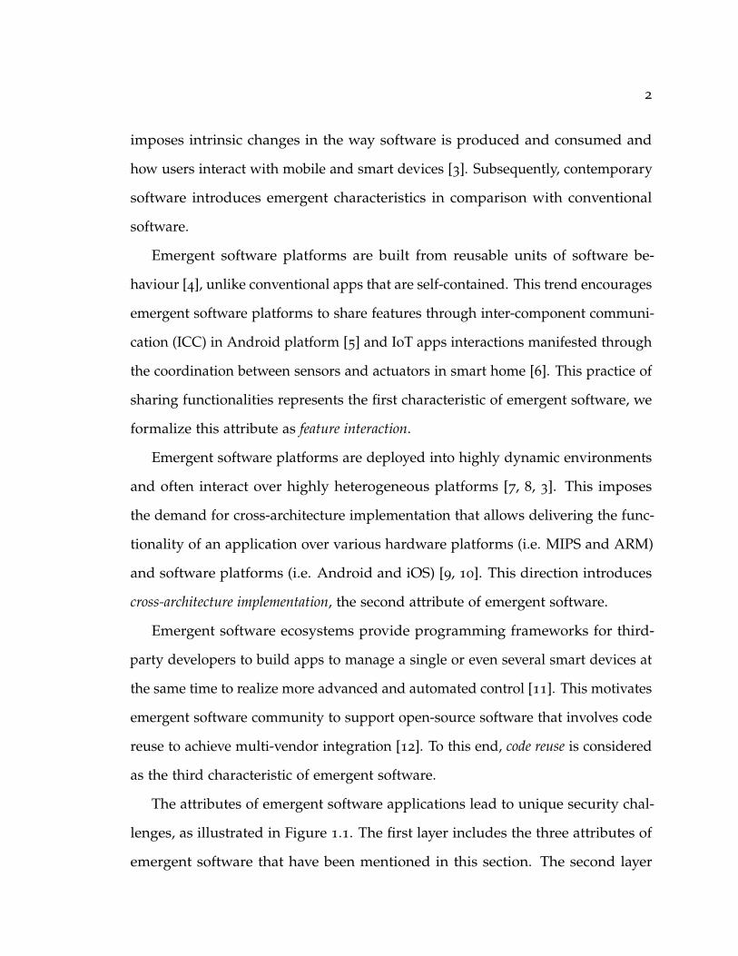
Emergent software platforms are built from reusable units of software be-
haviour [4], unlike conventional apps that are self-contained. This trend encourages
emergent software platforms to share features through inter-component communi-
cation (ICC) in Android platform [5] and IoT apps interactions manifested through
the coordination between sensors and actuators in smart home [6]. This practice of
sharing functionalities represents the first characteristic of emergent software, we
formalize this attribute as feature interaction.
Emergent software platforms are deployed into highly dynamic environments
and often interact over highly heterogeneous platforms [7, 8, 3]. This imposes
the demand for cross-architecture implementation that allows delivering the func-
tionality of an application over various hardware platforms (i.e. MIPS and ARM)
and software platforms (i.e. Android and iOS) [9, 10]. This direction introduces
cross-architecture implementation, the second attribute of emergent software.
Emergent software ecosystems provide programming frameworks for third-
party developers to build apps to manage a single or even several smart devices at
the same time to realize more advanced and automated control [11]. This motivates
emergent software community to support open-source software that involves code
reuse to achieve multi-vendor integration [12]. To this end, code reuse is considered
as the third characteristic of emergent software.
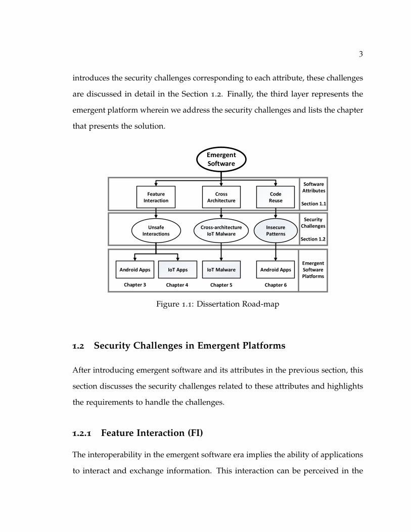
The attributes of emergent software applications lead to unique security chal-
lenges, as illustrated in Figure 1.1. The first layer includes the three attributes of
emergent software that have been mentioned in this section. The second layer
3
introduces the security challenges corresponding to each attribute, these challenges
are discussed in detail in the Section 1.2. Finally, the third layer represents the
emergent platform wherein we address the security challenges and lists the chapter
that presents the solution.
Android Apps
Emergent Software
Feature Interaction
Code Reuse
IoT AppsAndroid Apps
Software Attributes
Section 1.1
Android AppsEmergent Software Platforms
IoT Malware
CrossArchitecture
Unsafe Interactions
Insecure Patterns
Security Challenges
Section 1.2
Cross-architecture IoT Malware
Chapter 3 Chapter 4 Chapter 5 Chapter 6
Figure 1.1: Dissertation Road-map
1.2 Security Challenges in Emergent Platforms
After introducing emergent software and its attributes in the previous section, this
section discusses the security challenges related to these attributes and highlights
the requirements to handle the challenges.
1.2.1 Feature Interaction (FI)
The interoperability in the emergent software era implies the ability of applications
to interact and exchange information. This interaction can be perceived in the
4
Android platform through inter-app communication [13] and interactions between
sensors and actuators in the trigger/action ecosystem [14]. The interaction between
different components of the ecosystem is known as Feature Interaction, where the
behavior of one feature is influenced by the presence of another feature (or a
set of other features) [15, 16, 17, 18]. As a result, the feature interaction concept
provides value-added services and thus contributes to rich the user’s experience.
For example, an IoT app can provide energy-saving service by integrating an
air-conditioner, a ventilator, and thermometers [19]. Furthermore, applying the
concept of feature-interaction also reduces the developers’ burden and promotes
functionality reuse. For instance, in the context of the Android platform, the ability
to share pictures from one app with another [20], and a restaurant review applica-
tion can ask other applications to display the restaurantâAZs website, provide a
map with the restaurantâAZs location, and call the restaurant[21]. Nevertheless,
feature interaction is challenging traditional security analysis frameworks. First,
the number of interactions can be potentially exponential based on the number of
features [22]. Second, interactions cannot be deduced easily from the behaviors of
individual features. Third, the interaction introduces a new set of vulnerabilities
and safety issues such as resource contention, where features compete for resources
and loops in the communication among features [23]. Therefore, scalability aspect
should be handled efficiently in the proposed methods. The following subsection
discusses the feature interaction concept in the context of the Android and smart
home platforms.
1.2.1.1 Feature Interaction in the Android platform
The Android platform provides intent APIs to facilitate the interaction between
components within the app, which is known as Inter-Component Communica-
5
tion (ICC) or across-apps, known as Inter-app communication (IAC). Although
IAC improving users’ experience and reducing programming burden, it can be
exploited to perform collusive attacks [24]. To conceal this exploit, dynamic java
programming features such as Reflection and Dynamic Class Loading (DCL), can
be employed. The usage of dynamic programming features is justifiable because
its usage is expected to be growing in the appified era [2]. Java reflection mecha-
nism is extensively used in Android apps for maintaining backward compatibility,
accessing hidden/internal application program interface (API), providing external
library support, and reinforcing app security [25, 26]. But the use of the reflection
mechanism renders the security analysis approaches designed to analyze and
detect malicious apps ineffective [27]. As the malicious code is not part of the apps’
bytecode, rather is loaded at runtime using the dynamic class loading (DCL).
The current state-of-the-art security mechanisms, both static and dynamic
analysis approaches, are insufficient for detecting the increasingly sophisticated
security attacks.
Static analysis approaches [28, 29, 30, 31] can be easily bypassed by apps that
covertly invoke malicious IAC using reflection or DCL. On the other hand, dynamic
analysis approaches, such as TamiFlex [32], StaDyna [26], and DyDroid [33], suffer
from false negatives largely due to the reachability challenges, where vulnerabilities
are missed because of inputs that fail to reach the vulnerable code; they thus do
not detect malicious IACs concealed behind reflective and DCL calls. In Chapter 3,
we present a hybrid analysis approach for detecting such sophisticated behavior.
1.2.1.2 Feature Interaction in Smart Home Platform
In a smart home environment, the same set of sensors and actuators can be con-
trolled from different IoT platforms (i.e. SmartThings Groovy and SmartThings
6
IFTTT). This can lead to the race to configure, control, and monitor these de-
vices [34]. These platforms allow users to install third-party software apps that
automate the devices in their homes. Through their control of physical devices
in a system, software apps installed by the user can interact in both physical as
well as cyberspaces, allowing complex and varied automation. While enhancing
the user’s experience by delivering many options for automating their home, such
diversity at the same time escalates the attack surface for safety and security
threats. Interaction between smart home apps and devices can go beyond affecting
cyberspace to influencing the physical space, which might lead to severe safety
and security violations. Hence, identifying risky interactions is a pressing need.
This entails performing precise analysis that can assess the severity of interactions.
For instance, a door control app can be triggered to unlock the door when the user
arrives home, which is the desired behavior, but if the door unlocked while the
user is not present, this constitutes a serious hazard. This undesired behavior can
occur accidentally, or through unforeseen coordination between apps.
In this context, several techniques have been proposed in recent research to
identify possible safety and security violations in the IoT domain. However,
existing techniques provide an incomplete picture of the overall landscape of IoT
app interactions. In particular, the state-of-the-art techniques target only certain
types of inter-app attacks [34, 35, 11], do not take into account physical channels
through which apps can interact (such as temperature or moisture levels) [36],
which can underpin risky interactions, lack cross-platform analysis capability [34, 35],
which is necessary to analyze diverse systems that can interoperate in the same
IoT environment (e.g., Samsung SmartThings [37] and IFTTT [38]), and require
manual specification of the initial system configuration, which may lead to missing
potential unsafe behavior if it appears from different configurations [34]. Moreover,
7
these analyses have been shown to experience scalability problems when applied
on large numbers of IoT apps [34, 11, 35]. In Chapter 4, we present a compositional
analysis approach that can detect unsafe interaction threats in a given bundle of
cyber and physical components co-located in an IoT environment.
1.2.2 Cross-Architecture Malware
Interoperability in emergent software era is underpinned by developing cross-
architecture applications and firmwares [7, 8], which support various CPU archi-
tectures of IoT devices. This involves the ability to program across-architecture IoT
devices with a single compiler [9] and thus facilitating heterogeneous firmware
update instead of using monolithic binary updates. Moreover, promoting cross-
architecture implies the code base will be compiled with different compilers using
various configurations (e.g., different optimization levels). Cross-compile execution
will impose significant changes in the representation of the generated binaries [39].
In the IoT malware domain, Mirai malware was developed to infect differ-
ent architectures of IoT devices, as security researchers found binaries for the
common architecturesâATMIPS 32-bit, ARM 32-bit, and x86 32-bit belong to this
malware [40]. Mirai caused a major Internet service breakdown for a few hours
due to this cross-architecture capability, which supported the Mirai’s actor to infect
a large-scale of IoT devices [41]. Therefore, IoT devices have become enticing
targets for cyber-attackers. Since IoT devices are fully integrated into our daily life,
compromised devices can cause unprecedented damages. Even worse, IoT devices
are usually resource-constrained with low-profile processors, which prevents the
deployment of sophisticated host-based defenses as we commonly use on personal
computers (PCs). Consequently, the attackers endeavor to recruit vulnerable IoT

8
devices to build a large-scale bot army to launch the attack, and the number of IoT
malware has more than doubled in 2017 [42]. Therefore, in Chapter 5, we design a
lightweight cross-architecture signature generation scheme for detecting/classifying
IoT malware.
1.2.3 Code Reuse
Open-source application is a key aspect to facilitate the integration between the
heterogeneous systems in which emergent software platforms are deployed [43, 2,
44, 45]. Therefore, the software communities open-source the software develop-
ment [46], because open-source implementations support achieving multi-vendor
interoperability [12, 44, 45]. So that 91% of IoT developers adopt open-source
software at least one part of their development stack [2, 47].
However, this usage of others’ implementations can lead to the propagation of
security vulnerabilities [48, 44] because of weak programming practices [49]. The
code reuse is observed between open source software and online programming
discussion platforms (e.g., Stack Overflow) [50, 51, 52]. Several works showed that
insecure code patterns propagated in production software [53, 54, 55]. To mitigate
this issue, developers should be supported through a detection mechanism that can
identify insecure implementations at the early stage of a software implementation,
which consequently will promote the development of secure code. In Chapter 6
we identify insecure patterns of Secure Socket Layer/Transport Layer Security
(SSL/TLS) in the context of Android and develop detection rules that can be used
within the IDE.
This section discussed the security challenges that are considered in this dis-
sertation, which shows the complexity and the demand for reliable methods.
9
Therefore, conducting rigorous security analysis for addressing the implications of
these attributes requires: (1) performing a holistic analysis, (2) resolving scalability
aspects, and (3) modeling different elements of the applications that will impact
applications’ behavior. All these requirements represent a severe demand for
high levels of reliability and scalability in the proposed solutions. Section 1.3
summarizes our solutions to address these security challenges.
1.3 Research Contributions
In this dissertation, we propose four security analysis frameworks for addressing
the challenges discussed in the previous sections and illustrated in Figure 1.1. Each
project considers a specific challenge in the context of one of the emergent software
ecosystems. We make the following contributions in this dissertation:
1. FI in Android Platform: We analyze feature interactions in the context of An-
droid that manifested through inter-app communication (IAC). In this work,
we expose a new attack that leverages reflection and dynamic class loading
features in conjunction with inter-app communication to conceal malicious
attacks to bypass existing security mechanisms. we also show the interaction
between apps can lead to privacy leakage and spoofing attacks resulted from
the interactions of Android applications. To identify such vulnerabilities,
we design, develop and implement Dynamic INter-App Communication
Tool (Dina), a novel hybrid analysis approach for identifying malicious IAC
behaviors concealed within dynamically loaded code through reflective/DCL
calls. Dina appends reflection and DCL invocations to control-flow graphs
and continuously performs incremental dynamic analysis to detect the mis-
use of reflection and DCL that obfuscates Intent communications to hide

10
malicious IAC activities. Dina utilizes string analysis and inter-procedural
analysis to resolve hidden IAC and achieves superior detection performance.
This component of the dissertation is published in [56].
2. FI in smart home platform: we design and implement IotCom, a formal
method tool to identify safety and security violations that can occur in the
interactions between IoT apps in smart home environments. IotCom is
a compositional approach that empowers end-users to safeguard a given
bundle of cyber and physical components co-located in an IoT environment.
It automatically discovers such complicated interaction threats. IotCom
combines static analysis with lightweight formal methods to automatically
infer relevant specifications of IoT apps in an analyzable formal specification
language, taking into consideration the mapping between cyber and physical
channels. IotCom then checks the extracted specifications as a whole for
interaction threats.
3. Detecting Cross-architecture IoT Malware: we propose a data-driven sig-
nature generation method for detecting IoT malware, which generates dis-
tinguishable signatures based on high-level structural, statistical and string
feature vectors, as high-level features are more robust against code variations
across different architectures. The generated signatures for each malware
family can be used for developing lightweight malware detection tools to
secure IoT devices. The signature generation scheme extracts a reliable and
easily extractable string and statistical features. The string feature is ex-
tracted using N-gram text analysis, while the statistical feature contains the
code-level statistics. This work is published in [57]
11
4. Insecure implementation of SSL/TLS: this work aims to support developers
in detecting insecure SSL/TLS implementation in their codes in the context
of Android, whether this implementation is imported from other projects
or other platforms such Stack Overflow. Our approach utilizes a low-cost
cross-language static analysis tool called PMD. In the end, two insecure im-
plementations of SSL/TLS have been identified, and subsequently, a new
PMD ruleset is created. This ruleset consists of three rules for addressing
hostname validation vulnerability and certificate validation vulnerability. This
work is published in [58].
1.4 Organization
The rest of this dissertation is organized as follows: Chapter 2 presents the related
work of this work and puts it in the context of describing the limitations of prior
work. Chapter 3 presents our security analysis framework (namely Dina) for
detecting vulnerable Android Inter-App Communication in dynamically loaded
code. In Chapter 4, we introduce our formal method approach for detecting
unsafe interactions in the context of a smart home. In Chapter 5, we discuss our
approach for analyzing IoT malware and describe the data-driven framework for
cross-architecture signature generation. Chapter 6 describes our approach for
detecting code reuse in the context of StackOverflow. Finally, Chapter 7 concludes
this dissertation and provides an outlook on future research directions.

12
2 Related Work
In this chapter, we discuss research related to the work presented in this dissertation
and describes the limitation in prior work.
2.1 Android Inter-app Communication
This section discusses research efforts in the area of Android Inter-App Communi-
cation (IAC) and Inter-Component Communication (ICC). It then highlights the lim-
itations of the related solutions. Numerous techniques have been proposed to ana-
lyze inter-component communication vulnerabilities [59, 60, 61, 62, 63, 64, 31, 65].
Among others, IccTA [60] and its successor [62] leverage an Intent resolution
scheme to identify inter-component privacy leaks. However, their approach relies
on a preprocessing step connecting Android components through code instrumen-
tation, which can lead to scalability issues [31, 28]. Separ [29] and sealant [31]
perform compositional security analysis at a higher level of abstraction. While
these research efforts are concerned with security analysis of component interac-
tions between Android apps, DINA’s analysis enables reflection and DCL-aware
assessment of the overall security posture of a system, greatly increasing the scope
of potential ICC-based misbehavior analysis.
With respect to reflection and DCL, there have been several research efforts that
attempt to improve the soundness of static analysis in the presence of dynamically
13
loaded code through Java reflection. Livshits et al. [66] propose a static analysis
algorithm that can approximate reflection targets using points-to information. Felt
et al. [67] discuss the challenges of handling reflection in Android applications and
then attempt to address them using Stowaway, a static analysis tool that is capable
of identifying reflective calls and tracking reflection targets by performing flow-
sensitive analysis. More recent static analysis approaches aim to improve precision.
These approaches include DroidRA [25] and Sparta [68]. DroidRA adapts
TamiFlex [32] to statically analyze Android apps for dynamically loaded code.
Unlike TamiFlex, DroidRA does not execute apps; instead, it uses a constraint
solver to resolve reflection targets. It also uses its own version of Booster to
manipulate Jimple, an immediate representation used by Soot directly. TamiFlex,
on the other hand, manipulates Java bytecode. Sparta implements annotations
in the Checker framework to track information flow and a type inference system
to trace reflective calls. Sparta also operates at the source code level and not the
bytecode or dexcode level. However, these static analysis approaches can work
only in cases in which reflection targets can be identified from the source code.
For the most up-to-date and comprehensive review of static analysis approaches
for handling reflection, see Landman et al. [27]. Our approach however detects
reflection targets and captures dynamically loaded code using dynamic analysis.
There have also been several research efforts to perform dynamic analysis to
detect reflection/DCL targets. Davis et al. [69] provide an app rewriting framework
named RetroSkeleton that is capable of intercepting reflections at runtime; however,
this approach does not work with custom classloaders. Sawin et al. [70] propose
an approach that combines static string analysis with dynamic information to
resolve dynamic class loading via Java reflection. This approach operates only on
the standard Java library. Execute This! [71] is a dynamic analysis approach that

14
relies on an Android VM modification to detect reflection calls. It first logs runtime
events and then performs static analysis off-line. StaDynA [26] also performs
dynamic analysis in two phases. Our approach, on the other hand, performs
analysis continuously.
2.2 Smart home safety and security
This section discusses the stateof-the-art works that address the safety and securtiy
of smart home. IoT safety and security has been broadly studied recently [72, 11,
73, 74, 75, 76, 77, 35, 34, 36, 78, 79, 80, 81, 82, 83, 84, 85, 86, 87, 88, 89, 90, 91, 92,
93, 94, 95, 96, 97]. Many of these studies focus on data security issues such as
permission overprivilege [72, 98], or sensitive information leakage [74, 11, 73, 99].
ContextIoT [11] and SmartAuth [73] both detect and enforce authorization policies
at runtime to prevent such attacks. ProvThings [75] examines data security by
determining data provenance in IoT systems, and can log interactions between IoT
apps. However, these approaches primarily aim to protect sensitive data, and do
not detect safety and security violations arising from interactions of apps in the
physical world.
Soteria [35] reports violations either within a single app or between pairs of
apps, indicating a possible cap on its scalability. IoTSAN [34] detects violations
in bundles of more than two apps. However, the initial configuration of those
apps and their connected devices must be provided manually for each analysis.
Also, it must first translate the Groovy code of the SmartThings apps to Java,
limiting its analysis to just less than half (27 of 65) of the devices supported by
SmartThings [100]. In contrast, IotCom directly analyzes Groovy code, supports
large app bundles and all SmartThings device types, and is completely automated.
15
To the best of our knowledge, none of these approaches can detect violations
mediated by physical channels—a key feature of IotCom.
IoTMON [36] is a pure static analysis technique that analyzes rules based solely
on triggers, neglecting the conditions for specific actions. In contrast, IotCom
validates the safety of app interactions with more precision by effectively capturing
logical conditions influencing the execution of app rules through a precise control
flow analysis. Moreover, IoTMON does no analysis to detect potential safety and
security issues, which is conducted in a formally rigorous manner in IotCom.
Other researchers have evaluated the security of IFTTT applets [98, 76, 101, 102].
Fernandes et al. [98] studied OAuth security in IFTTT, while Bastys et al. [76] used
information flow analysis to highlight possible privacy, integrity, and availability
threats. However, none of the studies examined the aforementioned IoT safety
and security properties. In contrast, IotCom performs large scale safety and
security analysis, examining interactions between tens of IFTTT smart home
applets. IotCom also analyses bundles comprising both SmartThings Classic apps
and IFTTT applets, demonstrating its unique cross-platform analytical capability.
2.3 IoT Malware Detection
In this section, we focus on reviewing malware analysis approaches that aim at
classifying malware families and generating signatures for effective detection.
Malware Classification: Recently, Alazab [103] proposes a Windows malware
(in PE format) classification method based on features extracted dynamically
and statically from the malware files, including windows API sequences and
their frequencies of appearance. But the API calls are different across different
architectures, and can be easily forged or modified by attackers to disguise their

16
malicious activities. Santos et al.[104] present a malware classification method
based on the frequency of opcode sequences, but opcode sequences can also be
easily disrupted by simple code variations resulted from different compilation
options. Zynamics Bindiff [105] and BinSlayer [106] measure binary similarities
based on graph isomorphism between CFGs. BinSlayer further improves the binary
comparison accuracy of BinDiff by incorporating graph edit distances, but also
brings considerable overhead. Both Shabtai et al. and Hu et al. [107, 108] use
static analysis to examine the effectiveness of malware detection using OpCode
N-gram analysis. Kong et al. [109] map malware instances to their corresponding
malware family using structural features of function call graph and statistical
features including lists of API calls and opcodes with their respective frequencies.
Malware Signature Generation: High level string features and statistical features
extracted from file size and file content have been used to classify firmware images
of embedded devices [110]. Besides our different goals (known firmware classi-
fication versus unknown malware classification), they use a simple intersection
method on string features to identify firmware images, while our N-gram string
features can extract more representative features for each malware family. We also
consider statistical features by counting instructions and functions at the assembly
code level, which have finer granularity. Perdisc et al. [111] propose a multi-stage
clustering approach for generating malware signatures using the network traffic
generated by malware samples. FIRMA [112] also utilizes network traffic to gener-
ate behavioral signatures for malware detection. Unlike [111], FIRMA generates
network signatures for each network behavior regardless of traffic types, the format
of which follow popular signature-matching IDS. While the previous work deals
with generic PC malware, we focus on the newly emerging IoT malware.

17
2.4 Insecure SSL/TLS implementation Detection
In this section, we review related work that consider the insecure implementa-
tion of cryptograpy. FixDroid plug-in for Android studio has been developed
in [113], which addresses several limitations in Android Lint tool. It is used for
helping App developers in improving the quality of their code including insecure
implementations. FixDroid attempts to address the insecure implementations
of SSL/TLS. However, FixDroid only considers a single pattern, which is Im-
proper HostNameVerifier, while in our solution we consider three most commonly
observed patterns.
Another plug-in called CogniCrypt is developed for assisting developers in
generating secure implementation of crypto APIs [114]. This plug-in automatically
generates secure implementation instead of detecting insecure patterns using static
analysis technique. Although SSL API implementation is covered by the plug-in,
it does not show details about the type of SSL implementations that have been
covered.
HVLearn is a blackbox testing tool for verifying hostname ins SSL/TLS imple-
mentations based on automata learning algorithms [115]. However, developers do
not actually need blackbox testing techniques for detecting insecure implementa-
tion, as the source code is available. Also, HVLearn focuses only on detecting one
aspect of insecure SSL/TLS patterns.
Other solutions have been developed to detected insecure implementation
of SSL/TLS [116, 117]. However, these solutions intended to analyze released
applications and not to assist developers in detecting insecure patterns while
implementing SSL/TLS APIs.

18
3 Dina: Detecting Hidden Android Inter-App
Communication in Dynamic Loaded Code
Java reflection and dynamic class loading (DCL) are effective features for enhancing
the functionalities of Android apps. However, these features can be abused by
sophisticated malware to bypass detection schemes. Advanced malware can
utilize reflection and DCL in conjunction with Android Inter-App Communication
(IAC) to launch collusion attacks using two or more apps. Such dynamically
revealed malicious behaviors enable a new type of stealthy, collusive attacks,
bypassing all existing detection mechanisms. In this chapter, we present DINA, a
novel hybrid analysis approach for identifying malicious IAC behaviors concealed
within dynamically loaded code through reflective/DCL calls. DINA continuously
appends reflection and DCL invocations to control-flow graphs; it then performs
incremental dynamic analysis on such augmented graphs to detect the misuse of
reflection and DCL that may lead to malicious, yet concealed, IAC activities. Our
extensive evaluation on 3,000 real-world Android apps and 14,000 malicious apps
corroborates the prevalent usage of reflection and DCL, and reveals previously
unknown and potentially harmful, hidden IAC behaviors in real-world apps.

19
3.1 Background and Challenges
Android Apps: comprise different types of components, namely activities, services,
broadcast receivers, and content providers1. These components communicate through
a specific type of event messages called Intent, which can be either explicit, when its
recipient component is specified, or implicit, when no specific recipient component
is declared.
Inter-App Communication (IAC): Android apps typically use Inter-Component
Communication (ICC), a message passing mechanism (i.e. intent), to exchange
data. Components within or between apps use ICC to communicate with each
other via explicit or implicit Intents, depending on whether the target component
name is specified. The Android Intent is resolved at runtime based on the fields
of IntentFilter declared in the apps’ manifest files and the attributes of implicit
Intents, including action, category, and data. Intents can be sent through three types
of components (i.e., activities, services, receivers). Table 3.1 lists relevant Intent
sending and receiving APIs, categorized based on their corresponding component
types.
Components Intent-sending APIs Intent-receiving APIsReceivers sendBroadcast()
sendOrderedBroadcast()sendStickyBroadcast()sendStickyOrderedBroadcast()
onReceive()
Activities startActivity()startActivityForResult()
onCreate()
Services startService()bindService()
onStartCommand()
Table 3.1: A non-exhaustive list of Intent APIs.
Reflection and Dynamic code loading (DCL): DCL allows Android apps to load
and execute code that is not part of their initial code bases at runtime. DCL is
used to overcome some restrictions (i.e. 64K maximum method references in a1https://developer.android.com/guide/components/fundamentals.html

20
dex file) and extend the app’s functionality [26]. Java reflection is a language
feature that provides developers with the ability to inspect and determine program
characteristics, such as classes, methods and attributes, at runtime. Reflection is
used for maintaining backward compatibility, accessing hidden/internal applica-
tion program interface (API), providing external library support, and reinforcing
app security [25, 26]. Therefore, reflection and DCL have been used to enhance
functionalities of Android applications for legitimate purposes. But reflection and
DCL can also be used to hinder static analysis tools because they are resolved at
runtime. Fig. 3.1 illustrates a reflective call where the actual reflection targets (i.e.,
Classes B, C and D) cannot be resolved by static analysis tools as the malicious code
is not part of the apps’ bytescode, rather is loaded at runtime using the dynamic
class loading (DCL).
Class A Reflection API
Class B
Class C
Class D
...
...
Method.invoke(...)
Reflected Object
?
?
?
Figure 3.1: A typical reflective call used to defeat static analyzers.
Challenges: Analyzing the interactions among apps is a challenging task. The
obfuscation techniques such as reflection and DCL impose additional challenges.
We lay out the specific challenges in details below.
• The collaborative nature of Android apps indicates that the analyst needs to
be able to analyze a large collection of apps that can potentially interact, and
observe their collective runtime behaviors. Most existing program analysis
approaches cannot support such needs, because they tend to operate in a
close-world fashion (i.e., any change to the program under analysis requires

21
the entire analysis process to be rerun [118, 119]), require off-line processing
to generate analysis results, and can only analyze one app at a time.
• Reflection implies missing nodes and edges in the call graph, and thus the
control-flow and data-flow graphs regarding these missed nodes will not be
generated. Therefore, it is critical for the analyzers to have the capability of
resolving reflection and dynamically updating call graphs.
• DCL involves new codes that will be downloaded and executed at runtime.
The analyzers need to capture the newly downloaded code and then update
the call graph, control-flow and data-flow graphs at runtime.
3.2 Motivating Example
In this section, we present motivating examples to show how Intent can be used
as an attack vector to launch information leakage through hidden (dynamically
loaded) code, and to conceal method invocations through reflection.
Figure 3.2: Malicious app downloads code at runtime, and then uses it for leakingsensitive information.

22
1 public c l a s s DynLoadService extends S e r v i c e {2 public i n t onStartCommand ( I n t e n t i n t e n t ) { [ . . . ]3 loadCode ( ) ;4 }5 public void loadCode ( ) {6 // Read a j a r f i l e t h a t conta ins c l a s s e s . dex f i l e7 S t r i n g j a r P a t h =Environment . g e t E x t e r n a l S t o r a g e D i r e c t o r y ( ) . getAbsolutePath ( )
↪→ +"/dynamicCode.jar" ;8 // Load the code9 DexClassLoader mDexClassLoader = new DexClassLoader ( jarPath , getDir ( "dex" ,
↪→ MODE_PRIVATE) . getAbsolutePath ( ) ) ;10 // Use r e f l e c t i o n to load a c l a s s and c a l l i t s method11 Class <?> loadedClass = mDexClassLoader . loadClass ( "MalIAC" ) ;12 Method methodGetIntent = loadedClass . getMethod ( "getIntent" , android .
↪→ content . Context . c l a s s ) ;13 Object o b j e c t = loadedClass . newInstance ( ) ;14 I n t e n t i n t e n t = ( I n t e n t ) methodGetIntent . invoke ( o b j e c t , DynamicService .
↪→ t h i s ) ;15 s t a r t S e r v i c e ( i n t e n t ) ; } }
Listing 3.1: DynLoadService component resides in the malicious app andperforms DCL and reflection to hide its malicious behavior.
Fig. 3.2 presents a bundle of two apps, where a malicious IAC is initiated within
a dynamically loaded component from an external source to leak sensitive infor-
mation through the Messenger app. The DynLoadService component dynamically
loads a malicious class from an external JAR file placed at the location specified on
line 7 of Listing 3.1. It then instantiates a DexClassLoader object, and uses it to load
the DEX (Dalvik Executable) file contained in the JAR file. Using Java reflection
at line 12, the mDexClassLoader object loads a class called MalIAC and invokes
its getIntent method at line 14. This method returns an implicit Intent, which
DynLoadService uses to communicate with the Messenger Sender (line 15). Note that
MYSTIQUE-S [120] uses the same invocations in lines 9, 11-13 of Listing 3.1 for
constructing the attack template that loads the malicious payload on the fly.
Listing 3.2 depicts the hidden malicious class aiming at stealing users’ sensitive
information. On lines 3-4, getIntent obtains the sensitive banking information, and
then creates an implicit Intent with a phone number and the banking information
as the extra payload of the Intent (lines 5-8). This code is pre-compiled into

23
DEX format and archived to a JAR file. The JAR file could be downloaded by
the malicious app after installation. The Messenger app, as shown in Listing 3.3,
receives the Intent and sends a text message using the Intent payload, effectively
leaking sensitive data.
1 public c l a s s MalIAC {2 public I n t e n t g e t I n t e n t ( Context contex t ) {3 S t r i n g account = getBankAccount ( " Bank_Account " ) ;4 S t r i n g balance = getBankBalance ( " Balance_USD " ) ;5 I n t e n t i = new I n t e n t ( "SEND_SMS" ) ;6 i . putExtra ( "PHONE_NUM" , phoneNumber ) ;7 i . putExtra ( " Bank_Account " , account ) ;8 i . putExtra ( " Balance_USD " , balance ) ;9 return i ; } }
Listing 3.2: Malicious IAC component is concealed as external code andloaded at runtime after app installation.
1 public c l a s s MessageSender extends S e r v i c e {2 public void onStartCommand ( I n t e n t i n t e n t ) {3 S t r i n g number= i n t e n t . g e t S t r i n g E x t r a ( "PHONE_NUM" ) ;4 S t r i n g message= i n t e n t . g e t S t r i n g E x t r a ( "TEXT_MSG" ) ;5 sendTextMessage ( number , message ) ;6 }7 void sendTextMessage ( S t r i n g num, S t r i n g msg) {8 SmsManager mngr = SmsManager . ge tDefaul t ( ) ;9 mngr . sendTextMessage (num, null , msg , null , null ) ; } }
Listing 3.3: MessageSender resides in a benign app to receive Intents and sendtext messages.
Listing 3.4 presents an abbreviated code snippet from a real-world app (i.e.,
com.example.qianbitou) that uses reflection to conceal IAC behavior. The method
instantiate in the class Fragment (line 2) calls the reflection method newInstance() (line
4). This reflective call will initialize the constructor of the class _03_UserFragment
(line 6), and execute the method onClick() that invokes toCall(), which defines an
implicit Intent for making a phone call to a hard-coded number between 8am
and 10pm. The suspicious method toCall() is a private method concealed behind
reflective calls, which is difficult to capture in the analysis.

24
1 public c l a s s Fragment {2 public s t a t i c Fragment i n s t a n t i a t e ( ) {3 // R e f l e c t i o n c a l l s i t e4 paramContext = ( Fragment ) l o c a l C l a s s 1 . newInstance ( ) ; }5 }6 public c l a s s _03_UserFragment extends Fragment {7 public onClick ( ) {8 t o C a l l ( ) ;9 }
10 // The method invoked through the r e f l e c t i v e c a l l a t l i n e 4
11 private void t o C a l l ( ) {12 i n t i = Calendar . g e t I n s t a n c e ( ) . get ( ) ;13 i f ( ( i <= 22 ) || ( i >= 8 ) ) {14 s t a r t A c t i v i t y (new I n t e n t ( " android . i n t e n t . a c t i o n . DIAL" , Uri . parse ( " t e l
↪→ :4000−888−620 " ) ) ) ; } } }
Listing 3.4: Reflection is used to conceal IAC behavior in a real-world app
In order to detect the suspicious behaviors in the motivating examples, a
systematic approach is needed to resolve reflection/DCL and update the method
graphs dynamically. specifically, the proposed approach should 1) load the class
MalIAC in the DCL (Listing 3.2), 2) append the method getIntent (Listing 3.2) to
the method graph after resolving reflection, and 3) analyze the control-flow graphs
of loadCode (Listing 3.1) and getIntent to perform IAC analysis for detecting
suspicious IACs.
DINA is designed to load and resolve the reflective calls in Listings 3.1 and
3.4 at runtime. DINA’s dynamic analyzer automatically and incrementally aug-
ments both the control-flow and data-flow graphs with the newly loaded code
and resolved reflective calls. In tandem with the graph augmentation, DINA’s
vulnerability analyzer identifies potential malicious IAC activities on the fly. As
a result, DINA has the capability to precisely and efficiently detect the malicious
IAC behavior in the motivating examples although it is concealed by reflection.
25
3.3 Threat Model
This section describes the categories of suspicious inter-app communication behav-
iors that are considered in this work. The goal of the attacker considered in this
work is to launch stealthy inter-app attacks without being detected. Such stealthy
behavior can be manifested by different types of collusive attacks [121], where an
attacker uses the DCL and reflection mechanisms to obfuscate IAC behaviors of
the sender app and launch malicious behaviors, e.g., leaking sensitive information,
via another receiver app.
Our security analysis is centered around identifying the vulnerable IAC activities
that result in three types of serious threats: Information leakage, Intent spoofing, and
Android component activation, described as follows:
1. Information leakage happens when a receiver app exfiltrates the sensitive data
obtained through IAC communications from other apps and transmits it to
an external destination.
2. Intent spoofing is a security attack where the sender app forges Intents to
mislead receiver apps [21].
3. Android component activation happens when a malicious app intercepts an
implicit Intent by declaring an Intent filter matching the Intent, since the
Intent is not properly protected by permission restrictions [21].
We consider both explicit and implicit Intent. A malicious component refers to
a component that uses Intent sending/receiving APIs to help transfer malicious
Intents that contain sensitive information for data leakage, are forged for Intent
spoofing, or are received in an unauthorized manner. The data leaks are initiated by
a malicious component. Intent spoofing involves a path between two components

26
when the sender component is malicious, while unauthorized Intent receipt involves
a path between two components when the receiver component is malicious. DINA
is designed to detect all three types of security threats. Moreover, we consider the
IAC communication that involves more than two apps, i.e., DINA will be able to
capture collusive attacks concealed in a transitive ICC path through multiple apps.
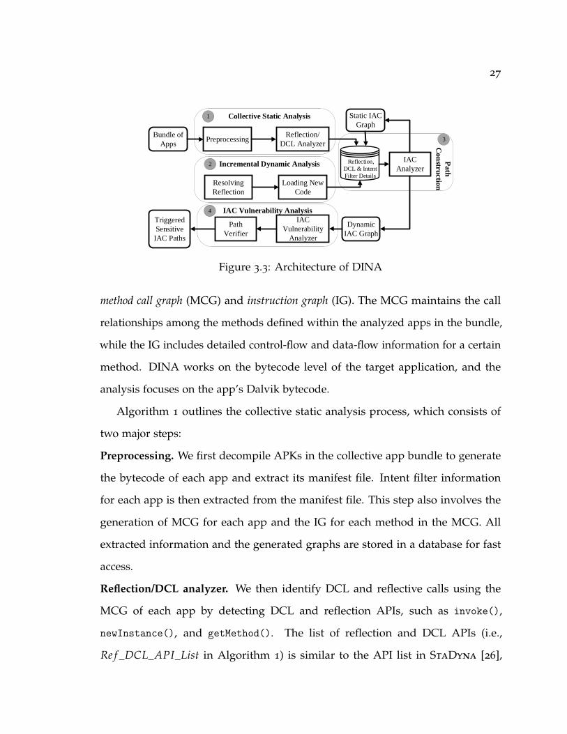
3.4 DINA System Design
This section presents DINA, a hybrid analysis tool for identifying sensitive IAC
paths that concealed through DCL and reflection. Fig. 3.3 illustrates DINA’s
architecture. DINA is a graph-centered hybrid analysis system that consists of three
main modules: 1) the collective static analysis module that simultaneously analyzes
multiple apps to automatically elicit DCL and reflection call sites within the
apps. The identified DCL and reflection call sites become the execution targets for
dynamic analysis; 2) the incremental dynamic analysis module that systematically
capturing new nodes and edges that are loaded at runtime by DCL and reflection;
3) the path construction module that generates the dynamic IAC graph that includes
all potential paths among the apps in the bundle. Specifically, it first generates
the static IAC graph, and then augments the static IAC graphs after receiving the
incremental updates; 4) the IAC vulnerability analysis module utilizes real-time IAC
graphs to identify potentially vulnerable paths.
3.4.1 Collective Static Analysis
The collective static analysis of DINA aims to statically identify the reflection, DCL
and IAC capabilities of each app in the app bundle, by analyzing multiple apps
at the same time. We generate two different types of graphs for each app, the
27
Preprocessing
Resolving
Reflection
Bundle of
Apps
Reflection/
DCL Analyzer
1
IAC
Vulnerability
Analyzer
Collective Static Analysis
2
4
Incremental Dynamic Analysis
IAC Vulnerability Analysis
Triggered
Sensitive
IAC Paths
Loading New
Code
IAC
Analyzer Reflection,
DCL & Intent
Filter Details
Dynamic
IAC Graph
Pa
th
Co
nstr
uctio
n
3
Static IAC
Graph
Path
Verifier
Figure 3.3: Architecture of DINA
method call graph (MCG) and instruction graph (IG). The MCG maintains the call
relationships among the methods defined within the analyzed apps in the bundle,
while the IG includes detailed control-flow and data-flow information for a certain
method. DINA works on the bytecode level of the target application, and the
analysis focuses on the app’s Dalvik bytecode.
Algorithm 1 outlines the collective static analysis process, which consists of
two major steps:
Preprocessing. We first decompile APKs in the collective app bundle to generate
the bytecode of each app and extract its manifest file. Intent filter information
for each app is then extracted from the manifest file. This step also involves the
generation of MCG for each app and the IG for each method in the MCG. All
extracted information and the generated graphs are stored in a database for fast
access.
Reflection/DCL analyzer. We then identify DCL and reflective calls using the
MCG of each app by detecting DCL and reflection APIs, such as invoke(),
newInstance(), and getMethod(). The list of reflection and DCL APIs (i.e.,
Re f _DCL_API_List in Algorithm 1) is similar to the API list in StaDyna [26],
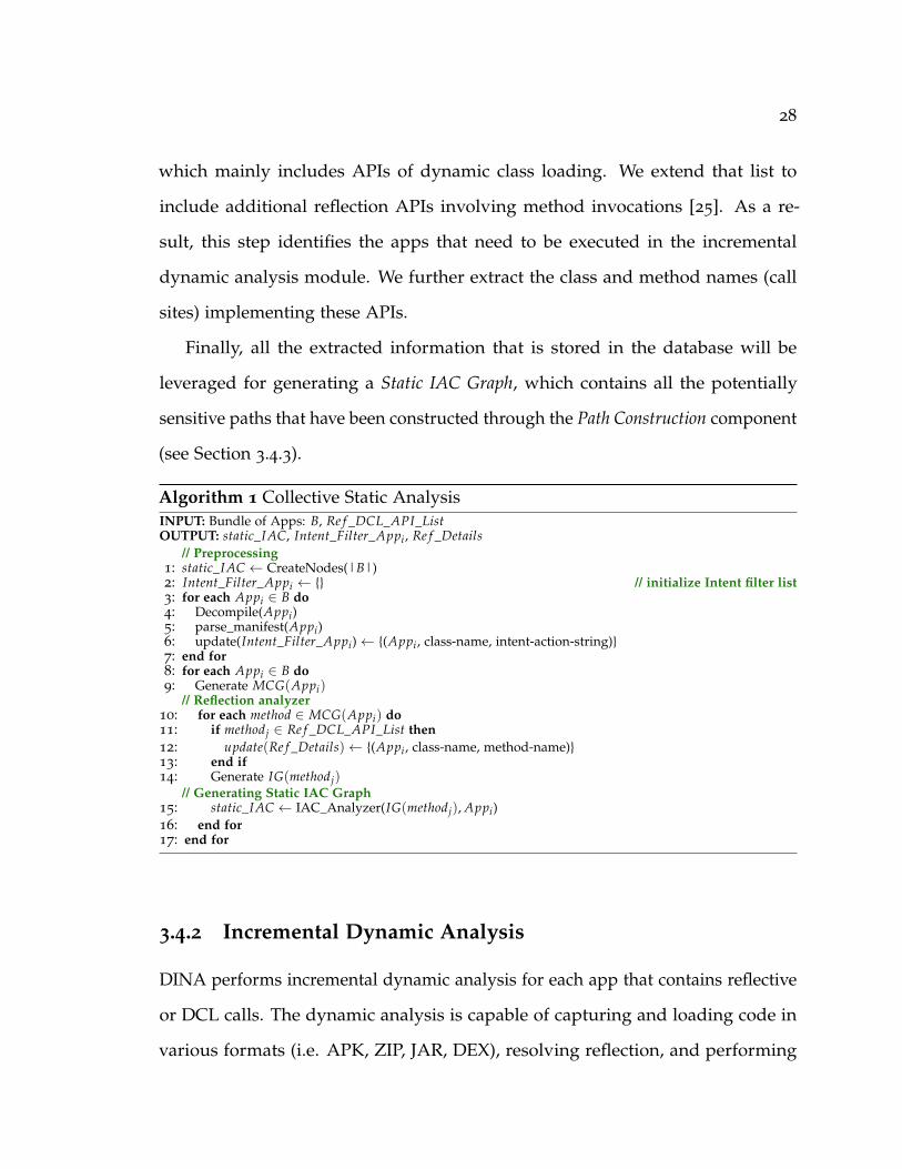
28
which mainly includes APIs of dynamic class loading. We extend that list to
include additional reflection APIs involving method invocations [25]. As a re-
sult, this step identifies the apps that need to be executed in the incremental
dynamic analysis module. We further extract the class and method names (call
sites) implementing these APIs.
Finally, all the extracted information that is stored in the database will be
leveraged for generating a Static IAC Graph, which contains all the potentially
sensitive paths that have been constructed through the Path Construction component
(see Section 3.4.3).
Algorithm 1 Collective Static AnalysisINPUT: Bundle of Apps: B, Re f _DCL_API_ListOUTPUT: static_IAC, Intent_Filter_Appi, Re f _Details
// Preprocessing1: static_IAC ← CreateNodes(|B|)2: Intent_Filter_Appi ← {} // initialize Intent filter list3: for each Appi ∈ B do4: Decompile(Appi)5: parse_manifest(Appi)6: update(Intent_Filter_Appi)← {(Appi, class-name, intent-action-string)}7: end for8: for each Appi ∈ B do9: Generate MCG(Appi)
// Reflection analyzer10: for each method ∈ MCG(Appi) do11: if methodj ∈ Re f _DCL_API_List then12: update(Re f _Details)← {(Appi, class-name, method-name)}13: end if14: Generate IG(methodj)
// Generating Static IAC Graph15: static_IAC ← IAC_Analyzer(IG(methodj), Appi)16: end for17: end for
3.4.2 Incremental Dynamic Analysis
DINA performs incremental dynamic analysis for each app that contains reflective
or DCL calls. The dynamic analysis is capable of capturing and loading code in
various formats (i.e. APK, ZIP, JAR, DEX), resolving reflection, and performing

29
IAC analysis incrementally with progressive augmentation of graphs. We modified
Android framework for resolving reflective calls and capturing newly loaded
codes at runtime. The incremental dynamic analysis consists of two major steps as
described below (see Algorithm 2).
Resolving reflection and loading new codes. Every app implementing reflection
and DCL will be executed on a real Android device or an emulator. This step
aims to capture the dynamic behaviors of the app. To reach the components that
implement reflection, we use the reflection details extracted and stored in the
database, which includes the component name and the corresponding method
name that implement reflection and DCL in each app. These methods/components
of an app, regarded as method of interest (MoI), will be exercised in the dynamic
analysis for resolving reflection and DCL call sites, which will augment the control-
flow and data-flow graphs dynamically.
We utilize a fuzzing approach to trigger the components that contain reflection
and DCL call sites. In the end, the static IAC graph will be refined by the IAC
analyzer to include all the IAC detected inside the dynamically loaded codes after
resolving reflection. New edges pertaining to the identified IAC are added to the
graph at runtime.
3.4.3 Path Construction
This component is used to generate the Static IAC Graph after performing the
collective static analysis, and it is also used to generate the Dynamic IAC Graph
by augmenting the Static IAC Graph after adding dynamic information that is
extracted through the Incremental Dynamic Analysis. Specifically, the IAC analyzer
30
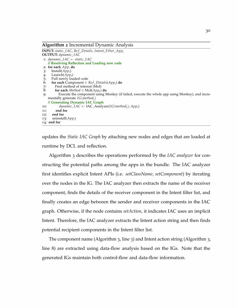
Algorithm 2 Incremental Dynamic AnalysisINPUT: static_IAC, Re f _Details, Intent_Filter_AppiOUTPUT: dynamic_IAC1: dynamic_IAC ← static_IAC
// Resolving Reflection and Loading new code2: for each Appi do3: Install(Appi)4: Launch(Appi)5: Pull newly loaded code6: for each Component ∈ Re f _Details(Appi) do7: Find method of interest (MoI)8: for each Method ∈ MoI(Appi) do9: Execute the component using Monkey (if failed, execute the whole app using Monkey), and incre-
mentally generate IG(methodj)// Generating Dynamic IAC Graph
10: dynamic_IAC ← IAC_Analyzer(IG(methodj), Appi)11: end for12: end for13: uninstall(Appi)14: end for
updates the Static IAC Graph by attaching new nodes and edges that are loaded at
runtime by DCL and reflection.
Algorithm 3 describes the operations performed by the IAC analyzer for con-
structing the potential paths among the apps in the bundle. The IAC analyzer
first identifies explicit Intent APIs (i.e. setClassName, setComponent) by iterating
over the nodes in the IG. The IAC analyzer then extracts the name of the receiver
component, finds the details of the receiver component in the Intent filter list, and
finally creates an edge between the sender and receiver components in the IAC
graph. Otherwise, if the node contains setAction, it indicates IAC uses an implicit
Intent. Therefore, the IAC analyzer extracts the Intent action string and then finds
potential recipient components in the Intent filter list.
The component name (Algorithm 3, line 3) and Intent action string (Algorithm 3,
line 8) are extracted using data-flow analysis based on the IGs. Note that the
generated IGs maintain both control-flow and data-flow information.

31
Algorithm 3 Path ConstructionINPUT: IG(methodj), Appi, Intent_Filter, Explicit_APIsOUTPUT: IAC_Graph
// Identify Intent Type1: for each node ∈ IG(methodj) do
// Explicit Intent2: if methodName ∈ Explicit_APIs then3: componentName = extractCompName(node)4: if componentName == Intent_Filter_Appr.component then5: IAC_graph ← addEdge(Appi, Appr)6: end if
// Implicit Intent7: else if methodName == setAction then8: stringAction == extractStrAction(node)9: if stringAction ∈ Intent_Filter_Appr.intent-action-string then
10: IAC_graph ← addEdge(Appi, Appr)11: end if12: end if13: end for
3.4.4 IAC Vulnerability Analysis
Algorithm 4 depicts the process of IAC vulnerability analysis, which consists of
two components including: 1) IAC vulnerability analyzer that marks sensitive
paths in the dynamic IAC graph, and 2) path verifier that automates the path
triggering process by installing the apps involved in the identified sensitive paths
and then triggering the corresponding APIs.
IAC vulnerability analyzer identifies whether the nodes in the dynamic IAC
graph constitute a vulnerable path that reveals sensitive information. IAC vulnera-
bility analyzer performs its analysis over all identified IAC paths in the dynamic
IAC graph. Then for each path, every node is analyzed, by identifying whether
it is a sender or receiver node, and then depth-first search (DFS) is conducted to
find if this node can reach a sensitive source method in case of sender node, or
can reach a sensitive sink in case the node is receiver. We leverage a sensitive API
list that simplifies the widely used SuSi list [122] to identify these sensitive APIs.
An inverted DFS searches from the recorded MoI (identified in Algorithm 2) to
seek sensitive sources, while another DFS searches from Intent-receiving method

32
at the receiver (line 12 in Algorithm 4) to look for sensitive sinks. Finally, it marks
the complete sensitive paths from the sensitive source to the sensitive sink across
multiple apps. Fig. 3.4 represents a typical sensitive path that links sensitive source
API to a sensitive sink through IAC after resolving the reflection/DCL calls. Note
that these paths are stealthy and difficult to find, as they only appear after loading
dynamic codes and resolving reflection calls, but they can be captured by DINA
efficiently.
Path verifier tries to automatically trigger the sensitive paths in the dynamic IAC
graph. A sensitive path contains a sensitive source and a sensitive sink node (cf.
Fig. 3.4, Algorithm 4, line 28). After identifying the sensitive path, the pather
verifier checks the type of reflection/DCL call site class. If the type is an activity,
the sender and receiver apps will be installed on our tablet device. We use adb
utility to execute the activity component and record the generated log using logcat
utility. Finally, the path will be considered as a triggered path if the log contains
the exercised activity, the Intent string action, and the name of the receiver app.
Sensitive Source
Reflection/DCL Calls
Intent Sending Method
Intent Receiving Component
Sensitive Sink
invoke
Sender App Receiver App
IAC
Figure 3.4: A simplified sensitive path example: the dashed method and paths canbe captured during DINA’s dynamic analysis phase.
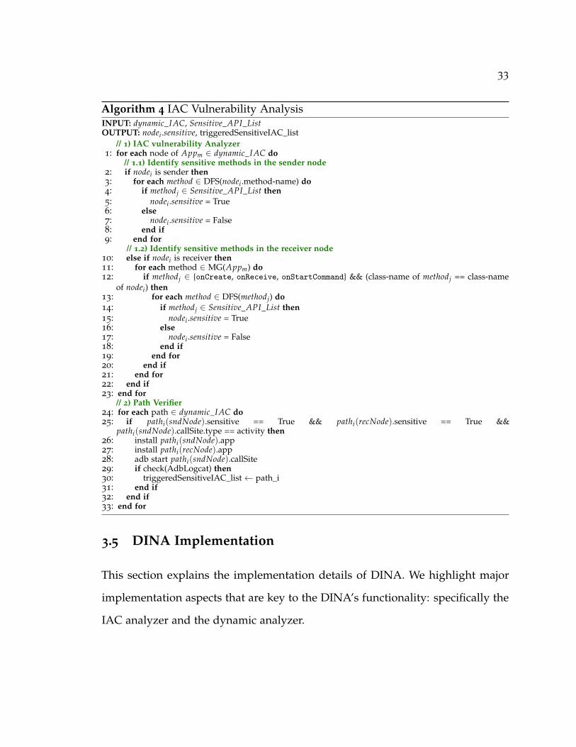
33
Algorithm 4 IAC Vulnerability AnalysisINPUT: dynamic_IAC, Sensitive_API_ListOUTPUT: nodei.sensitive, triggeredSensitiveIAC_list
// 1) IAC vulnerability Analyzer1: for each node of Appm ∈ dynamic_IAC do
// 1.1) Identify sensitive methods in the sender node2: if nodei is sender then3: for each method ∈ DFS(nodei.method-name) do4: if methodj ∈ Sensitive_API_List then5: nodei.sensitive = True6: else7: nodei.sensitive = False8: end if9: end for
// 1.2) Identify sensitive methods in the receiver node10: else if nodei is receiver then11: for each method ∈ MG(Appm) do12: if methodj ∈ {onCreate, onReceive, onStartCommand} && (class-name of methodj == class-name
of nodei) then13: for each method ∈ DFS(methodj) do14: if methodj ∈ Sensitive_API_List then15: nodei.sensitive = True16: else17: nodei.sensitive = False18: end if19: end for20: end if21: end for22: end if23: end for
// 2) Path Verifier24: for each path ∈ dynamic_IAC do25: if pathi(sndNode).sensitive == True && pathi(recNode).sensitive == True &&
pathi(sndNode).callSite.type == activity then26: install pathi(sndNode).app27: install pathi(recNode).app28: adb start pathi(sndNode).callSite29: if check(AdbLogcat) then30: triggeredSensitiveIAC_list← path_i31: end if32: end if33: end for
3.5 DINA Implementation
This section explains the implementation details of DINA. We highlight major
implementation aspects that are key to the DINA’s functionality: specifically the
IAC analyzer and the dynamic analyzer.
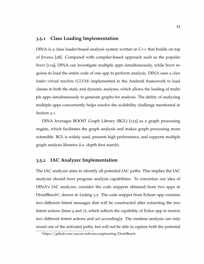
34
3.5.1 Class Loading Implementation
DINA is a class loader-based analysis system written in C++ that builds on top
of Jitana [28]. Compared with compiler-based approach such as the popular
Soot [119], DINA can investigate multiple apps simultaneously, while Soot re-
quires to load the entire code of one app to perform analysis. DINA uses a class
loader virtual machine (CLVM) implemented in the Android framework to load
classes in both the static and dynamic analyses, which allows the loading of multi-
ple apps simultaneously to generate graphs for analysis. The ability of analyzing
multiple apps concurrently helps resolve the scalability challenge mentioned in
Section 3.1.
DINA leverages BOOST Graph Library (BGL) [123] as a graph processing
engine, which facilitates the graph analysis and makes graph processing more
extensible. BGL is widely used, presents high performance, and supports multiple
graph analysis libraries (i.e. depth first search).
3.5.2 IAC Analyzer Implementation
The IAC analyzer aims to identify all potential IAC paths. This implies the IAC
analyzer should have program analysis capabilities. To concretize our idea of
DINA’s IAC analyzer, consider the code snippets obtained from two apps in
DroidBench2, shown in Listing 3.5. The code snippet from Echoer app contains
two different Intent messages that will be constructed after extracting the two
Intent actions (lines 4 and 7), which reflects the capability of Echor app to receive
two different Intent actions and act accordingly. The runtime analysis can only
reveal one of the activated paths, but will not be able to capture both the potential2https://github.com/secure-software-engineering/DroidBench
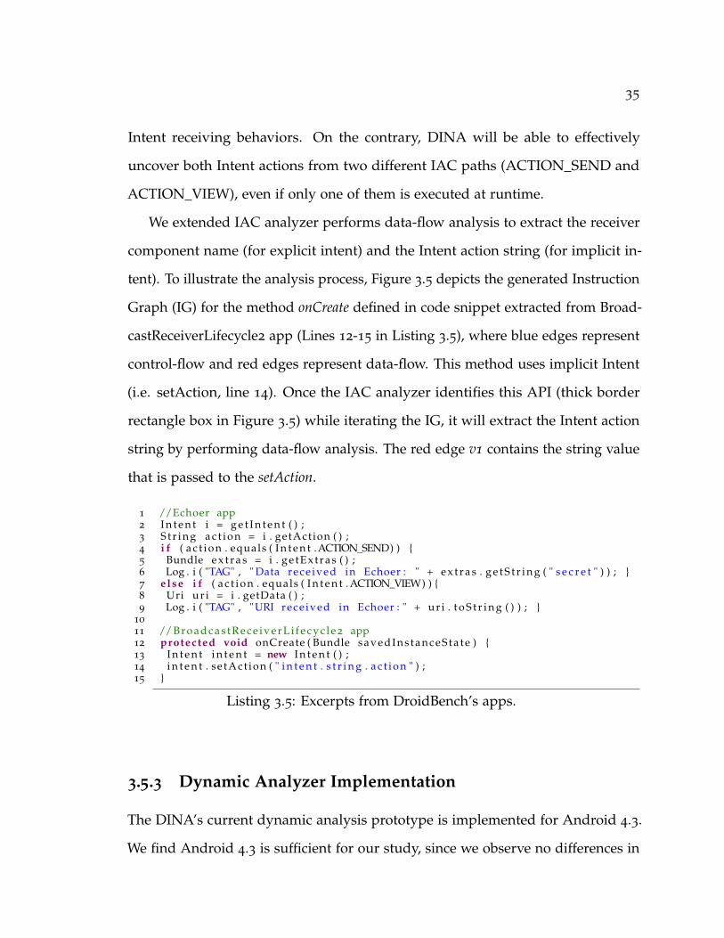
35
Intent receiving behaviors. On the contrary, DINA will be able to effectively
uncover both Intent actions from two different IAC paths (ACTION_SEND and
ACTION_VIEW), even if only one of them is executed at runtime.
We extended IAC analyzer performs data-flow analysis to extract the receiver
component name (for explicit intent) and the Intent action string (for implicit in-
tent). To illustrate the analysis process, Figure 3.5 depicts the generated Instruction
Graph (IG) for the method onCreate defined in code snippet extracted from Broad-
castReceiverLifecycle2 app (Lines 12-15 in Listing 3.5), where blue edges represent
control-flow and red edges represent data-flow. This method uses implicit Intent
(i.e. setAction, line 14). Once the IAC analyzer identifies this API (thick border
rectangle box in Figure 3.5) while iterating the IG, it will extract the Intent action
string by performing data-flow analysis. The red edge v1 contains the string value
that is passed to the setAction.
1 //Echoer app2 I n t e n t i = g e t I n t e n t ( ) ;3 S t r i n g a c t i o n = i . getAct ion ( ) ;4 i f ( a c t i o n . equals ( I n t e n t .ACTION_SEND) ) {5 Bundle e x t r a s = i . g e t E x t r a s ( ) ;6 Log . i ( "TAG" , " Data rece ived in Echoer : " + e x t r a s . g e t S t r i n g ( " s e c r e t " ) ) ; }7 e lse i f ( a c t i o n . equals ( I n t e n t .ACTION_VIEW) ) {8 Uri u r i = i . getData ( ) ;9 Log . i ( "TAG" , "URI rece ived in Echoer : " + u r i . t o S t r i n g ( ) ) ; }
10
11 //B r o a d c a s t R e c e i v e r L i f e c y c l e 2 app12 protected void onCreate ( Bundle s a ve d I n s ta n c e S t a t e ) {13 I n t e n t i n t e n t = new I n t e n t ( ) ;14 i n t e n t . se tAct ion ( " i n t e n t . s t r i n g . a c t i o n " ) ;15 }
Listing 3.5: Excerpts from DroidBench’s apps.
3.5.3 Dynamic Analyzer Implementation
The DINA’s current dynamic analysis prototype is implemented for Android 4.3.
We find Android 4.3 is sufficient for our study, since we observe no differences in

36
ENTRY
1 0 (line=17) new-instance v0 [1_0_t30]
5 11 invoke-virtual v2 v0 [1_0_m5225]
v2
2 2 invoke-direct v0 [1_0_m156]
v0
4 8 invoke-virtual v0 v1 [1_0_m188]methodName: setAction
v0
v03 5 const-string/jumbo v1 [intent.string.action]
v1
6 14 return-void []
EXIT
Figure 3.5: Instruction Graph for the method onCreate (Listing 3.5) that includesboth control-flow and data-flow.
DCL-related APIs between Android 4.3 and Android 7.1. This observation is also
confirmed by Qu et al. [33]. Currently, we have begun porting DINA to support
ART, the latest Android run-time system. The modified version of Android 4.3 is
adopted to keep incrementally capture newly downloaded codes, which includes
JAR, DEX and APK. We utilize Java Debug Wire Protocol (JDWP) over Android
Debug Bridge(ADB) [124] to pull the newly downloaded codes from the real device
(Nexus 7 tablet) that we used for running our experiments.
In the dynamic analysis, we utilize Monkey to generate a series of random user
inputs to reach the components that contain reflection/DCL APIs. Specifically, the

37
class names extracted in the static analysis phase that contain reflective calls are
used for constructing component names that will be exercised by Monkey. Then,
each component is executed at three times with different seeds in each execution
to better cover the component. In the end, more reflective calls can be reached and
executed at runtime. For instance, if the identified component is an activity with
a button-click handler that triggers a reflective call that leads to IAC operations,
Monkey will click that button to activate the hidden IAC operation.
3.6 Evaluation
This section presents our experimental evaluation of DINA. We conduct our
evaluation to answer the following four research questions:
• Question 1: How accurate is Dina in identifying vulnerable IAC/ICC activi-
ties compared to the state-of-the-art static and dynamic analyses?
• Question 2: How robust is Dina in analyzing the capabilities/behaviors of
reflection and DCL implementations in real-world apps?
• Question 3: How effective is Dina in detecting vulnerabilities in real-world
apps?
• Question 4: How efficient is Dina in performing hybrid analysis?
3.6.1 How accurate is Dina?
Evaluating the accuracy of Dina requires performing the analysis on a ground
truth dataset, where the attacks are known in advance. This constitutes a major
challenge due to the lack of existing colluding apps [125], specifically benchmark
38
apps that are using reflection and DCL for performing malicious IAC. We found 12
suitable Benchmark apps (listed in Table 3.2) from DroidBench and other resources
to validate Dina’s detection effectiveness and efficiency, all of which perform ICC
or IAC through reflection or DCL.
Comparing with static analysis tools. Next, we consider three state-of-the-art
static analysis systems: IccTA [126], SEALANT [31], and DroidRA [25] designed to
identify suspicious IAC and reflection activities. DroidRA focuses on detecting
reflective calls using composite constant propagation. IccTA is a static analysis tool
that can detect vulnerable ICC paths using inter-component taint analysis based
on FlowDroid. SEALANT combines data-flow analysis and compositional ICC
pattern matching to detect vulnerable ICC paths.
To construct a baseline system that shares the same capability as Dina, we
attempted to integrate these two types of techniques: DroidRA was used to resolve
reflective calls, while IccTA and SEALANT were used to detect vulnerable IACs in
targets captured by DroidRA. Here, we compare Dina’s reflection resolution and
IAC detection performance with other baseline approaches.
Comparing reflection resolution performance: we compare reflection/DCL reso-
lution capabilities of Dina and DroidRA over benchmark and real-world apps.
We found that DroidRA was able to resolve reflective calls in 8 out of 12 bench-
mark apps in Table 3.2. DroidRA did not detect any reflective calls in OnlyTele-
phony_Reverse.apk and OnlyTelephony_Substring.apk, and it crashed during the
inter-component analysis of DCL.apk. The only app that DroidRA can success-
fully analyze and annotate with reflection targets is reflection11.apk. On the other
hand, Dina has resolved all reflection and DCL calls in the benchmark apps. For
real-world apps, our results show that Dina can detect more reflective calls than

39
DroidRA. For instance, for a malware sample3 that contains 14 reflective calls
and 4 DCL calls. DroidRA detects 11 of them, while Dina captures all reflec-
tive/DCL calls. This is because DroidRA fails to detect the reflective calls within
the dynamically loaded code.
Comparing IAC detection performance: we perform ICC/IAC analysis using
SEALANT and IccTA over the instrumented benchmark apps by DroidRA. Al-
though DroidRA successfully resolved the reflective calls of 8 benchmark apps, it
was not able to correctly instrument the apps with those reflection targets required
for IAC analysis. Our results indicate that many of these targets reside within
the Android framework, and thus are not considered in the analysis conducted
by DroidRA. We also found that while the annotated APK is structurally correct,
it can no longer be executed. Moreover, we observed that SEALANT yields in-
valid results after analyzing the instrumented APKs by DroidRA, which may be
caused by the incompatibility of the generated APK format with SEALANT’s input.
Therefore, we did not use the instrumented APKs, instead we used DroidRA’s
reported reflection resolution results, and then use these results in conjunction with
SEALENT and IccTA’s results to identify vulnerable IAC paths within benchmark
apps.
Table 3.2 shows IAC detection comparison results in terms of precision, recall
and F-measure scores. Note that we did not report the results of IccTA because it
can only produce results for 5 out of 12 apps (ActivityCommunication2, OnlyIntent,
OnlySMS, reflection11, and SharedPreferences1), but fails to detect any vulnerabilities.
SEALANT performs better in a number of benchmarks, yet produces several false
positives that affects its precision.3MD5: 00db7fff8dfbd5c7666674f350617827

40
Table 3.2: IAC detection performance comparison between DroidRA+SEALANTand Dina. True Positive (TP), False Positive (FP), and False Negative (FN) are
denoted by symbols 2�, 4, 2, respectively. (X#) represents the number # ofdetected instances for the corresponding symbol X. Also note that IccTA did not
detect any vulnerable paths.
Test Cases DroidRA+SEALANT Dina
ActivityCommunication2 2�(43) 2�AllReflection 2�(43) 2�OnlyIntent 2 2�OnlyIntentReceive 2�(42) 2�OnlySMS 2�(43) 2�OnlyTelephony 2�(43) 2�OnlyTelephony_Dynamic 2�(43) 2�OnlyTelephony_Reverse 2 2�OnlyTelephony_Substring 2 2�SharedPreferences1 2 2Reflection_Reflection11 2� 2�Dynamic class loading 2 2�Precision 29.2% 100%Recall 58.3% 91.6%F-measure 38.9% 95.62%
The experimental results show that Dina can handle reflective and DCL calls
to de-obfuscate ICC, and reaches 100% precision and 91.6% recall in detecting
vulnerable ICC. As for the app SharedPreferences1, Dina detects the reflective calls,
but misses its ICC path, because the shared preference mechanism used in the app
is not considered by Dina.
Comparing with dynamic analysis tools. As for the dynamic analysis approach,
the most closely-related technique is HARVESTER [127], which uses program
slicing to deobfuscate reflective calls for dynamic execution, yet we were informed
by the authors that neither the source code nor the binary version of HARVESTER
is available. Moreover, HARVESTER’s precision was not evaluated over benchmark

41
apps, which makes it hard to compare against. IntentDroid [128] is a dynamic
analysis tool for detecting vulnerable IAC, but it cannot deal with reflection/DCL.
3.6.2 How robust is Dina?
In this section, we evaluate Dina’s capabilities to reveal the behavior of reflec-
tion/DCL classes in complex, real-world apps. We used three datasets with 49, 000
real-world apps, including: 1) 31, 894 apps from AndroZoo project4, 2) 3, 000
most popular apps from Google Play store, and 3) 14, 294 uncategorized malware
samples from VirusShare5.
Reflection/DCL Usage Landscape. We first performed the collective static analysis
of Dina using the three previously-mentioned sets of apps to identify reflection
and DCL call sites. The experimental results show that 92.0% (i.e., 26,361/ 31,894)
of AndroZoo apps implement reflection calls, and 51.1% (i.e., 16,313/31,894) of
them implement DCL calls. This shows the wide adoption of DCL and reflection
mechanisms in Android apps. More remarkably, 99.4% of 3, 000 popular apps
implement reflection calls, and 90.1% of them implement DCL calls. Therefore,
reflection and DCL mechanisms are even more widely adopted in popular apps.
For the malware apps, 85.0% implement reflection mechanism, while only 24.3% of
them adopt DCL mechanism. Solely based on our evaluation, it seems that fewer
malware apps use the DCL mechanism. Note that Dina counts the number of APIs
by traversing the whole method graph, which produces an accurate representation
of the apps under analysis.
We then run the dynamic analysis on the popular apps and randomly-picked
malicious apps. Table 3.3 presents the results, from which we can see that the4androzoo.uni.lu5virusshare.com

42
number of activated classes in the benign apps significantly exceeds that of the
malicious apps.
We also perform further analysis to identify the entity, either the app itself or a
third-party library, behind the activated reflection and DCL classes. Note that we
ignore the Android framework classes.
We can see most of the activated reflection/DCL classes are included in third-
party APIs in both malicious and benign apps, as has been confirmed by prior
research [33].
Table 3.3: Dynamic analysis of real-world apps.
Dataset # of in-stalledApps
# of appscontainreflec-tion/DCL
# of ac-tivatedreflec-tion/DCL
% of 3rdpartyclasses
% of app-ownedclasses
Benign 1,957 1,271 17,170 85.6% 7.66%Malicious 2,378 1,033 7,336 54.6% 5.18%
Intent sending/receiving capabilities of DCL/reflection classes. Next, we evalu-
ate Dina’s incremental dynamic analysis to detect Intents in dynamically loaded
code. We analyze the activated reflection/DCL classes of popular and malicious
apps to identify the Intent sending and receiving APIs presided within the re-
flection/DCL classes. Table 3.4 presents the number of Intent sending APIs and
receiving APIs. We use DFS as a reachability test to find whether MoI can reach
the Intent sending APIs as shown in Table 3.4.
Table 3.4: Intent sending and receiving capabilities of activated ref/DCL classes.
Dataset # of Intent sending APIs(reachable)
# of Intent receivingAPIs
Benign 1022 (936) 146
Malicious 600 (390) 79

43
Sensitive sources within DCL/reflection classes. Table 3.5 presents the top 10
sensitive sources in the activated reflection and DCL classes in both benign and
malicious apps. These sensitive sources can reach Intent-sending APIs concealed
by reflection/DCL to leak sensitive information, including device ID, subscriber
ID, etc.
Table 3.5: Top sensitive sources in the activated reflection and DCL classes.
Benign MaliciousSensitive APIs Freq. Sensitive APIs Freq.
getInstalledApplications() 113 getSubscriberId() 35
getMacAddress() 100 getSSID() 29
getCountry() 42 getMacAddress() 7
getActiveNetworkInfo() 33 getDeviceId() 6
getInstalledPackages() 21 getCountry() 6
openConnection() 20 getInstalledPackages() 6
getDeviceId() 7 openConnection() 4
getSubscriberId() 1 getSimSerialNumber() 2
Our analysis reveals that apps can indeed conceal their IAC communication
capabilities inside dynamically loaded classes. The experimental results show that
the total number of matched Intent action strings is 18, with the top-7 matched
strings depicted in Table 3.6. android.net.conn.CONNECTIVITY_CHANGE is the
most matched Intent action string appearing after the reflective calls. Among all
these dynamically executed apps, 38 apps are found to contain matched Intent
strings, which means these apps can potentially perform stealthy IAC activities
through reflection and DCL calls.
3.6.3 How effective is Dina?
In our experiment, we found some concealed IAC vulnerabilities that have been
effectively detected by Dina, as presented in Table 3.7. We have manually triggered
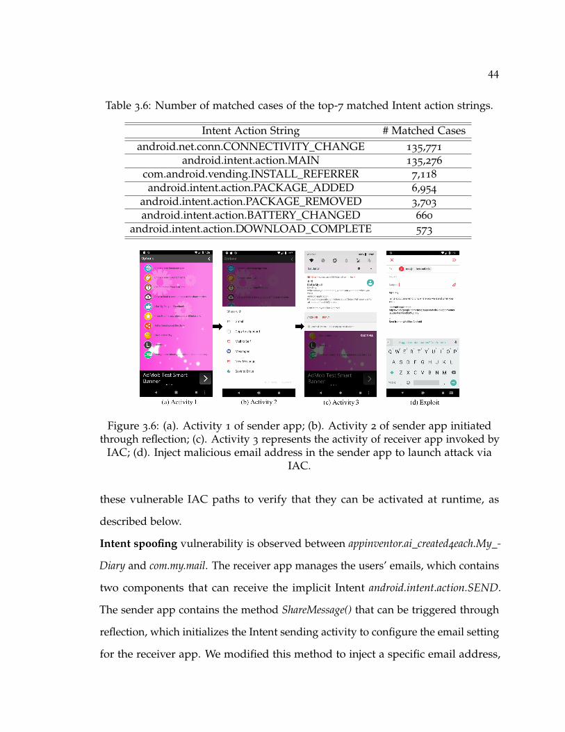
44
Table 3.6: Number of matched cases of the top-7 matched Intent action strings.
Intent Action String # Matched Casesandroid.net.conn.CONNECTIVITY_CHANGE 135,771
android.intent.action.MAIN 135,276
com.android.vending.INSTALL_REFERRER 7,118
android.intent.action.PACKAGE_ADDED 6,954
android.intent.action.PACKAGE_REMOVED 3,703
android.intent.action.BATTERY_CHANGED 660
android.intent.action.DOWNLOAD_COMPLETE 573
Figure 3.6: (a). Activity 1 of sender app; (b). Activity 2 of sender app initiatedthrough reflection; (c). Activity 3 represents the activity of receiver app invoked by
IAC; (d). Inject malicious email address in the sender app to launch attack viaIAC.
these vulnerable IAC paths to verify that they can be activated at runtime, as
described below.
Intent spoofing vulnerability is observed between appinventor.ai_created4each.My_-
Diary and com.my.mail. The receiver app manages the users’ emails, which contains
two components that can receive the implicit Intent android.intent.action.SEND.
The sender app contains the method ShareMessage() that can be triggered through
reflection, which initializes the Intent sending activity to configure the email setting
for the receiver app. We modified this method to inject a specific email address,
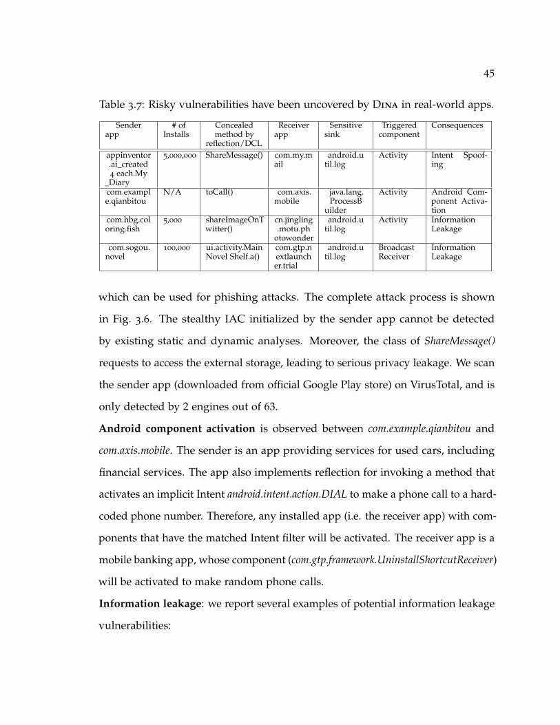
45
Table 3.7: Risky vulnerabilities have been uncovered by Dina in real-world apps.
Senderapp
# ofInstalls
Concealedmethod by
reflection/DCL
Receiverapp
Sensitivesink
Triggeredcomponent
Consequences
appinventor.ai_created4 each.My
_Diary
5,000,000 ShareMessage() com.my.mail
android.util.log
Activity Intent Spoof-ing
com.example.qianbitou
N/A toCall() com.axis.mobile
java.lang.ProcessB
uilder
Activity Android Com-ponent Activa-tion
com.hbg.coloring.fish
5,000 shareImageOnTwitter()
cn.jingling.motu.ph
otowonder
android.util.log
Activity InformationLeakage
com.sogou.novel
100,000 ui.activity.MainNovel Shelf.a()
com.gtp.nextlauncher.trial
android.util.log
BroadcastReceiver
InformationLeakage
which can be used for phishing attacks. The complete attack process is shown
in Fig. 3.6. The stealthy IAC initialized by the sender app cannot be detected
by existing static and dynamic analyses. Moreover, the class of ShareMessage()
requests to access the external storage, leading to serious privacy leakage. We scan
the sender app (downloaded from official Google Play store) on VirusTotal, and is
only detected by 2 engines out of 63.
Android component activation is observed between com.example.qianbitou and
com.axis.mobile. The sender is an app providing services for used cars, including
financial services. The app also implements reflection for invoking a method that
activates an implicit Intent android.intent.action.DIAL to make a phone call to a hard-
coded phone number. Therefore, any installed app (i.e. the receiver app) with com-
ponents that have the matched Intent filter will be activated. The receiver app is a
mobile banking app, whose component (com.gtp.framework.UninstallShortcutReceiver)
will be activated to make random phone calls.
Information leakage: we report several examples of potential information leakage
vulnerabilities:

46
• vulnerability is observed between com.hbg.coloring.fish and cn.jingling.motu.
photowonder. The sender is a gaming app, and the receiver app is an image
editing app. The sender app contains a reflective call that instantiates an
implicit Intent for sending pictures from the mobile storage. We also observed
this concealed method invokes a sensitive API (queryIntentActivities) to obtain
the running activities on the mobile device. The implicit Intent can be
received by any app that contains android.intent.action.SEND. This vulnerable
IAC path may lead to the leakage of sensitive images, and it can be very
harmful when both apps are managed by one party.
• this case is observed between com.sogou.novel and com.gtp.nextlauncher.trial.
The sender app is a reader app, while the receiver app is used for 3D image
processing. The reflection implemented in this app executes an implicit Intent
android.intent.action.SEND for activating a broadcast receiver component of
the receiver app. The implicit Intent sends information about a book, which
can be easily replaced by sensitive information (e.g., bank accounts, location).
This vulnerability can also be exploited to perform denial of service attack
on the receiver app, by repeatedly invoking the implicit intent to send the
broadcast messages.
• the vulnerability constituted between com.slideme.sam.manager and com.google.android.
googlequicksearchbox. The sender is a mobile apps store, and the receiver app
is a google search service. The sender app contains a reflective call that
instantiates an implicit Intent (android.speech.action.RECOGNIZE_SPEECH)
for sending voice records. The complete attack process is shown in Fig. 3.7,
and the captured log confirms the activated IAC activity. This vulnerable IAC
path may be used to spy on the user and leak voice records. This vulnerability

47
can be exploited to instruct Google Now to send messages to third parties.
Such vulnerability has been demonstrated by AVG team [129], which can
cause harmful consequences in which voice recognition techniques are used
to perform voice impersonation attacks.
(a) Activity 1
(b) Activity 2 (c) Activity 3
(d) Captured Log
Figure 3.7: (a). Activity 1 of sender app; (b). Activity 2 of sender app initiatedthrough reflection; (c). Activity 3 represents the activity of receiver app invoked by
IAC; (d). Captured log confirms the IAC.
3.6.4 How efficient is Dina?
App stores including Google Play receive thousands of new apps every day, all of
which require comprehensive security analysis. Therefore, we need efficient tools
that can scale to the size of a large app market. We next report the running time
of Dina’s app analysis. We report the analysis time for both static analysis phase
and dynamic analysis phase. The performance reported in this section was run
on a Nexus 7 tablet connecting to a MacBook Pro laptop with Intel Core 2 Duo

48
2.4 GHz CPU and 8 GB memory. The static analysis was conducted on the laptop,
while the dynamic analysis was performed on the tablet.
Fig. 3.8 shows the static analysis time with respect to the app bundle size in
megabytes (MBs). With the growing app bundle sizes, the analysis time appears
to be stable. For most of the bundles, Dina can finish the static analysis within 1
minute, demonstrating the efficiency of Dina’s static analyzer. Fig. 3.9 presents the
running time of dynamic analysis for 1, 000 real-world popular apps. The result
shows that over 90% of apps can finish the dynamic analysis within 5 minutes. The
majority of the dynamic analysis time is spent on running the apps to boost the
coverage, and this time cost is inevitable for dynamic analysis tools. For complex
apps with an average app size of 42 MBs, Dina can accomplish the dynamic
analysis within 2.5 minutes/app on average as similar to the analysis time of
HARVESTER, showing that Dina can be used for large-scale security analysis.
0
10
20
30
40
50
60
70
0 100 200 300 400
DIN
A's
Stat
ic A
naly
sis
Tim
e (s
)
App Bundle Size (MB)
Figure 3.8: Static analysis time.
0
0.1
0.2
0.3
0.4
0.5
0.6
0.7
0.8
0.9
1
50 100 200 300 400 500 600
CD
F of
App
s (%
)
DINA's Dynamic Analysis Time (s)
Figure 3.9: Dynamic analysis time.
We further compared Dina’s runtime performance with the state-of-the-art
IAC analysis tools, i.e., SEALANT and DroidRA, using the set of benchmark apps
(cf. Section 3.6.1). Fig. 3.10 shows the results of performance comparison. Dina
achieves the best performance for the majority of the apps (8 out of 12), with an
average analysis time of 1 minute/app.

49
0102030405060708090
Anal
ysis
Tim
e (s
)
DroidRA SEALANT DINA
Figure 3.10: Runtime performance comparison.
3.7 Discussion
Dynamic analysis coverage. Improving coverage has been a major challenge for
dynamic analysis approaches [130]. In Dina, we currently utilize Monkey for input
generation to exercise the targeted components. Although we achieve excellent
IAC detection performance, we may still suffer from potential false negatives. We
inherit some of the input generation limitations of Monkey. However, this fuzzing
approach is still widely used by recent approaches that target DCL (e.g., Dy-
Droid [33]), which relies on the observation that third-party libraries launch their
DCL events when starting the app, which is sufficient for our analysis. Further-
more, the empirical study performed in [131] shows Monkey has achieved the best
coverage among all analyzed input generation tools including DynoDroid [132]
and PUMA [133].
IntelliDroid [134] is a recently-proposed input generation tool using event-chain
detection and input injection with constraint solver. We integrate Intellidroid with
Dina to replace Monkey. However, it fails to trigger most of the reflective/DCL
50
calls. We found that most of the statically-identified paths related to reflective
calls cannot be successfully triggered by Intellidroid, mainly due to the limited
input type support, the limitations in the constrain solver, and its lack of support
in dealing with environmental contexts/variables.
Furthermore, a malicious app may perform emulator detection to halt its
malicious activities during the analysis. Dina addresses this issue by performing
the analysis on real devices.
IAC detection accuracy. Compared with static and dynamic tainting analysis
based approaches, Dina does not perform precise data flow tracking analysis,
which may lead to the imprecision of our detection results. Thus, the static
analysis results may contain false positives. However, we use dynamic analysis
to narrow down the scope of analysis on the methods that are dynamically ex-
ecuted. Therefore, we can effectively alleviate the imprecision brought by the
lack of tainting analysis. One major benefit of our approach, however, is the
improvement on runtime performance as shown in Section 3.6.4 compared to other
approaches.Furthermore, existing static IAC analysis cannot handle an Intent that
has been obfuscated in a manifest file. In such scenario, static analysis cannot
identify app pairs by simply matching the Intents.
3.8 Summary
In this chapter, we present Dina, a hybrid analysis approach for detecting malicious
IAC activities in dynamically loaded code. Dina utilizes a systematic approach
based on control-flow, data-flow, and method call graphs to identify malicious
IAC activities across multiple apps. We have shown Dina can effectively resolve
reflective and DCL calls at runtime for real-world apps. We demonstrate that

51
multi-app, colluding attacks concealed by reflection and DCL can be launched to
perform stealthy attacks, and evading existing detection approaches. In particular,
we discover several popular real-world apps, which can trigger vulnerable IAC
activities through reflection and DCL, leading to surreptitious privacy leakage.
We have compared Dina with existing IAC vulnerability and reflection analysis
tools. Dina analyzes most of apps in less than five minutes, and can identify
malicious IAC behaviors concealed by reflective calls that no previous approach
was able to detect. We believe further effort is required to better regulate the usage
of reflection and DCL calls to close the attack avenues without undermining their
utilities.
52
4 IotCom: Compositional Safety and Security
Analysis of IoT Systems
The ubiquity of Internet of Things (IoT) and our growing reliance on IoT apps are
leaving us more vulnerable to safety and security threats than ever before. Many of
these threats are manifested at the interaction level, where undesired or malicious
coordinations between apps and physical devices can lead to intricate safety and
security issues. This chapter presents IotCom, an approach and accompanying
tool suite, to automatically discover such hidden and unsafe interaction threats
in a compositional, yet scalable, fashion. It is backed with automated program
analysis and formally rigorous violation detection engines. IotCom relies on
program analysis to automatically infer the relevant app’s behavior. Using a
novel strategy to trim the extracted app’s behavior prior to translating them to an
analyzable formal specification, IotCom mitigates the state explosion associated
with formal analysis. Our experiments with numerous bundles of real-world IoT
apps have corroborated IotCom’s ability to effectively detect a broad spectrum of
interaction threats triggered through cyber and physical channels, many of which
were previously unknown, and to significantly outperform the existing techniques
in terms of scalability.
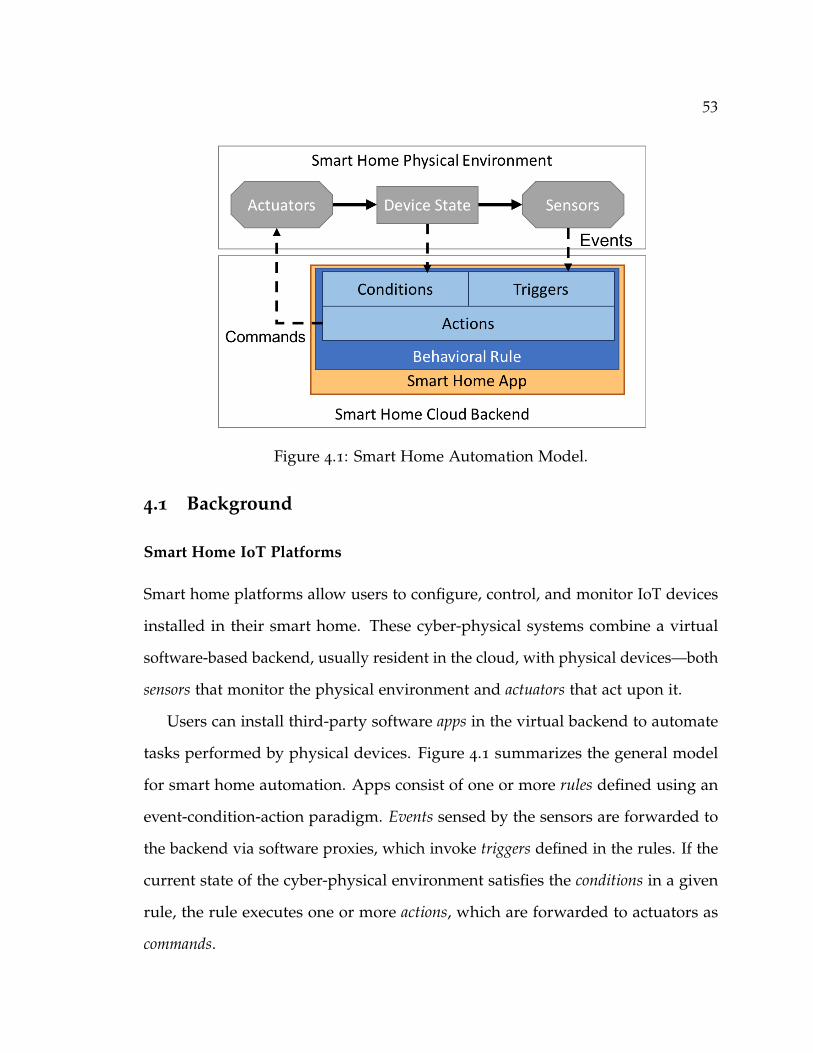
53
Figure 4.1: Smart Home Automation Model.
4.1 Background
Smart Home IoT Platforms
Smart home platforms allow users to configure, control, and monitor IoT devices
installed in their smart home. These cyber-physical systems combine a virtual
software-based backend, usually resident in the cloud, with physical devices—both
sensors that monitor the physical environment and actuators that act upon it.
Users can install third-party software apps in the virtual backend to automate
tasks performed by physical devices. Figure 4.1 summarizes the general model
for smart home automation. Apps consist of one or more rules defined using an
event-condition-action paradigm. Events sensed by the sensors are forwarded to
the backend via software proxies, which invoke triggers defined in the rules. If the
current state of the cyber-physical environment satisfies the conditions in a given
rule, the rule executes one or more actions, which are forwarded to actuators as
commands.

54
Apps come from either vendor-specific marketplaces, such as Samsung’s Smart-
Things [37] and Google Home [135], or from cross-platform services like IFTTT [38].
Each framework defines and distributes apps differently. In IFTTT, for example,
each app is a single trigger-action rule that responds to and actuates via RESTful
web services. Other vendors allow for more complicated rules. Among others,
Samsung SmartThings Classic apps [37] are defined as Groovy programs, and
Alexa skills can be defined in any language supported by AWS Lambda [136].
Smart Home IoT Safety and Security
The convenience provided by the proliferation of automations and app market-
places also presents challenges for smart home safety and security. The smart home
app environment is collaborative, in that all installed apps or automations interact
with each other, via both cyber and physical channels. Bugs, misconfiguration, or
even malicious intent by app developers all present a threat of undesired behavior.
End users may have to set complex configuration options without clear documen-
tation, and some marketplaces allow third-party apps to be published by any
developer with little to no oversight [76, 137]. Indeed, the concealed risks inherent
in the complex coordination of third-party smart home apps can be very serious,
ranging from data access issues such as permission misuse and data leakage to
compromising the home’s physical safety [138, 139].
The wide variety of app marketplaces and the diversity of APIs and specifica-
tions complicate any holistic safety analysis; analyzing the apps installed in even
one smart home would involve multiple platforms, programming languages, and
channels of coordination. While various recent approaches [34, 11, 74, 102, 78, 140,
141, 142] have attempted to chip away at the challenges underlying such analysis,

55
most focus on a single aspect of the problem [143, 72, 98, 74, 11, 73, 144] or on a
single app platform [36, 35, 11, 75, 78, 73, 72, 76].
In the following sections, we present an approach that can holistically analyze
safety properties of coordinating app bundles spanning multiple automation
platforms as well as both cyber and physical channels.
4.2 Illustrative Example
This section illustrates an unsafe interaction between IoT apps using a simple
example, shown in Figure 4.2. The example comprises three IoT apps—one
malicious (MaliciousApp) and two benign. HomeModeApp changes the heating status
of the oven based on the “mode” of the smart home system. The mode is a general,
customizable setting used for automation that generally tracks whether the user is
home or away or if it is day or night. FireAlarmApp opens the door when smoke
is detected. MaliciousApp represents a third-party app that pretends to perform a
benign activity but instead modifies the smart home’s mode, unbeknownst to the
home owner.
The detrimental interaction occurs when MaliciousApp switches the smart home
mode to Home. This triggers HomeModeApp, which turns on the heating element in
the oven. The oven may in turn activate the smoke detector, triggering FireAlarmApp
to open the door. Together, the interaction of the apps compromises the safety of
the home by opening the door when no one is at home. Such unsafe interactions
occur in real-world, as demonstrated in prior research [36].
Identifying such perilous interactions is challenging due to both the variety of
ways apps may communicate and the multiplicity of apps involved in each interac-
tion. The challenge is exacerbated by considering the concealed interactions, such

56
Malicious
AppHomeModeApp FireAlarmApp
Location
Smoke
Trigger:
ModeAction: set
LocationMode
Action:
oven.heating
Action:
door.open
Trigger:
detected
Figure 4.2: An example of malicious IoT apps interaction.
as the interaction between HomeModeApp and FireAlarmApp. In this case, HomeMod-
eApp activates the oven, which does not concern FireAlarmApp; nonetheless, the two
apps interact via the oven’s heating element and the smoke detector. An analysis
must be able to elucidate those hidden channels as well as holistically analyze
all interactions in the system. For example, the individual interactions between
MaliciousApp and HomeModeApp and between HomeModeApp and FireAlarmApp each
could be benign. It is only when put together that the three apps compromise the
IoT environment’s safety.
4.3 Safety Goals for IoT App Interactions
This work focuses on identifying security and safety violations resulting from
interactions among IoT apps installed in the same smart home environment. At a
high level, these apps are intended to make the home owner’s life more convenient
and should only act on devices when intended and in a predictable, safe manner.
Apps that are safe individually may begin to exhibit unintended, unpredictable, or
unsafe behavior when multiple apps interact. We have identified three high-level
goals that safe operation of IoT apps should satisfy:
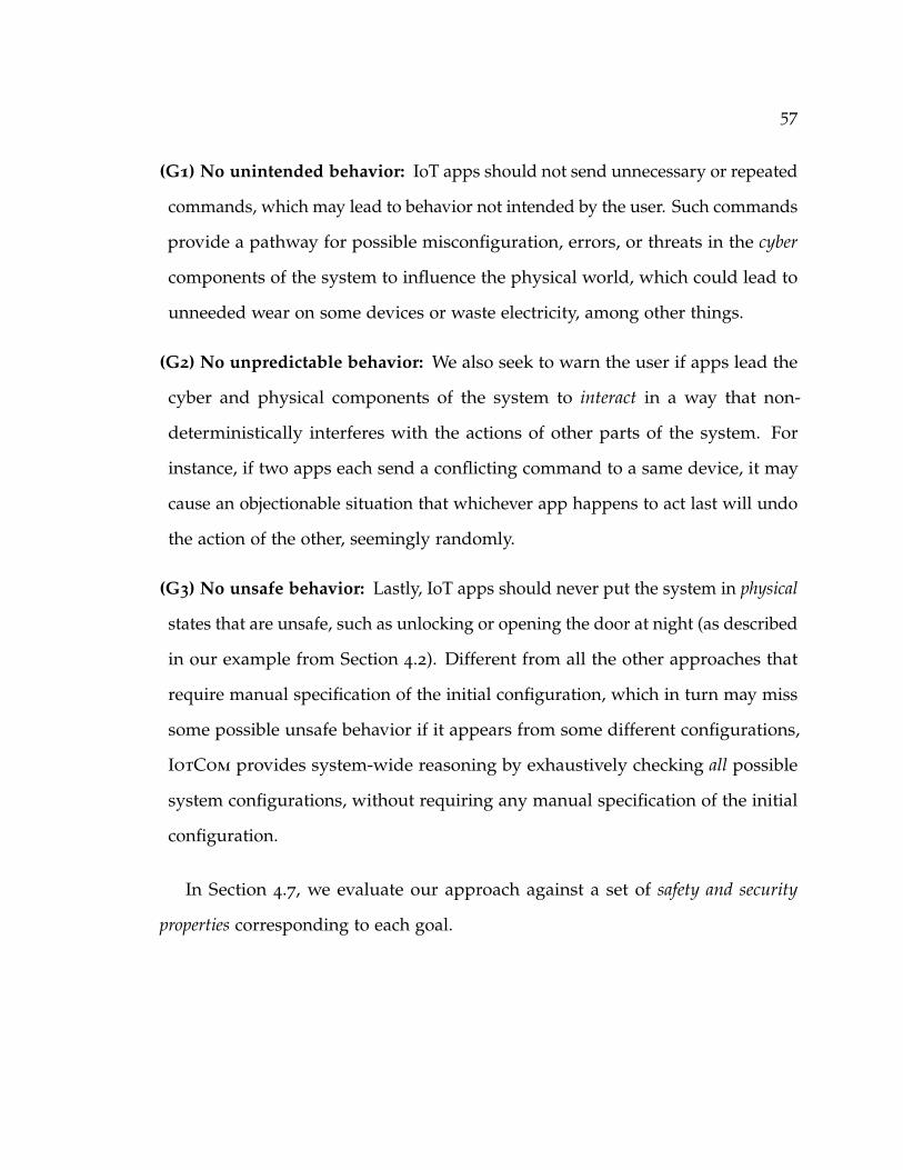
57
(G1) No unintended behavior: IoT apps should not send unnecessary or repeated
commands, which may lead to behavior not intended by the user. Such commands
provide a pathway for possible misconfiguration, errors, or threats in the cyber
components of the system to influence the physical world, which could lead to
unneeded wear on some devices or waste electricity, among other things.
(G2) No unpredictable behavior: We also seek to warn the user if apps lead the
cyber and physical components of the system to interact in a way that non-
deterministically interferes with the actions of other parts of the system. For
instance, if two apps each send a conflicting command to a same device, it may
cause an objectionable situation that whichever app happens to act last will undo
the action of the other, seemingly randomly.
(G3) No unsafe behavior: Lastly, IoT apps should never put the system in physical
states that are unsafe, such as unlocking or opening the door at night (as described
in our example from Section 4.2). Different from all the other approaches that
require manual specification of the initial configuration, which in turn may miss
some possible unsafe behavior if it appears from some different configurations,
IotCom provides system-wide reasoning by exhaustively checking all possible
system configurations, without requiring any manual specification of the initial
configuration.
In Section 4.7, we evaluate our approach against a set of safety and security
properties corresponding to each goal.

58
4.4 Approach Overview
This section introduces IotCom, a technique that automatically determines whether
the interactions within an IoT environment could compromise the safety and
security thereof. Figure 4.3 illustrates the architecture of IotCom and its two major
components:
(1) Behavioral Rule Extractor (Section 4.5): The Behavioral Rule Extractor com-
ponent automatically infers models of the apps behavior using a novel graph
abstraction technique. The component first performs static analysis on each app
to generate an inter-procedural control flow graph (ICFG). It then creates a behav-
ioral rule graph containing only the flows pertinent to the events and commands
forwarded to/from the physical devices in the smart home, along with any con-
ditions required for those actions. Each flow is then automatically transformed
into a formal model of the app.
(2) Formal Analyzer (Section 4.6): The Formal Analyzer component analyzes
these models through bounded model checking. IotCom relies on three formal
specifications: (1) a base model of smart home IoT systems that defines a set of
rules to lay the foundation of cyber and physical channels, IoT apps, how they
behave, and how they interact with each other, (2) assertions for safety and security
properties, and (3) the IoT app behavioral rule model that Rule Extractor generates
automatically for each IoT app. The set of specifications are then checked as a
whole for violations of relevant safety properties.
Finally, a report is returned to the user describing the list of detected interaction
vulnerabilities. Upon reviewing the report, end-users and third-party reviewers
may choose to protect their system in a variety of ways, e.g., by disallowing
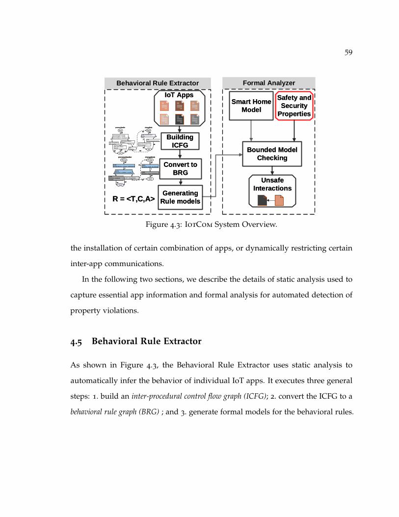
59
Behavioral Rule Extractor Formal Analyzer
IoT Apps
Building
ICFG
Convert to
BRG
Generating
Rule models
Smart Home
Model
Bounded Model
Checking
Unsafe
Interactions
R = <T,C,A>
Safety and
Security
Properties
Entry
Exit
L(13): def evtValue = evt.value
L(14): def evtName = evt.name
L(15): if (evtValue == “not present”)
L(16): if(state.sunMode =
“sunset”)L(20): def timeStamp
L(21): log.debug “...”
L(17):
changeMode
NP
T
T
NPNP
F
L(19): state.sunMode =
“sunrise”
F
NP
Entry
Exit
L(28): if (location.mode !=
Home)
L(29):
setLocationMode(HomeMode)
L(31): mode = location.mode
L(32): log.debug “...”
NP
T
NP
F
NP
NP
NP
precenseHandler changeMode
Entry
Exit
L(15):
(contactSensor, contact, notPresent)
L(16):
(location, sunMode, sunset)
L(17): changeMode
T
F
NP
NP
L(19):
(location, sunMode,
sunset)
NP
T
Entry
ExitNP
NP L(28):
(location, mode, not_Home)
L(29):
(location, mode, HomeMode)
T
NP
NP
precenseHandler changeMode
Figure 4.3: IotCom System Overview.
the installation of certain combination of apps, or dynamically restricting certain
inter-app communications.
In the following two sections, we describe the details of static analysis used to
capture essential app information and formal analysis for automated detection of
property violations.
4.5 Behavioral Rule Extractor
As shown in Figure 4.3, the Behavioral Rule Extractor uses static analysis to
automatically infer the behavior of individual IoT apps. It executes three general
steps: 1. build an inter-procedural control flow graph (ICFG); 2. convert the ICFG to a
behavioral rule graph (BRG) ; and 3. generate formal models for the behavioral rules.

60
4.5.1 Building ICFG
The Behavioral Rule Extractor first generates an inter-procedural control flow
graph for each app. It analyzes the abstract syntax tree of the given app to build
a call graph of local and API-provided methods as well as a control flow graph for
each local method. Each graph is generated using a path-sensitive analysis [145]
to preserve the logical conditions along each control flow. This improves the
precision of our approach compared to the state-of-the-art techniques, which do
not account for the conditions when identifying interactions between apps. It then
combines each control flow graph with the call graph to construct an ICFG starting
at each entry method in the graph. Entry methods are framework-specific methods
invoked in response to events in the smart home backend software; for example,
SmartThings defines a subscribe API that allows developers to specify custom
event handlers.
4.5.1.1 ICFG Example: IFTTT
The details of generating the ICFG depend on how apps are defined for each
platform. For example, IFTTT applets are reactive rules that interact with REST
services exposed by smart home vendors or other service providers [146]. Each
applet consists of a single trigger-action pair, without any conditions. IotCom
treats each applet as a standalone IoT app defining exactly one rule. The Behavioral
Rule Extractor performs string analysis [147] to extract an ICFG comprising a single
entry node for the trigger and a single “method call” invoking a device API for the
action. For instance, IFTTT applet “If I arrive at my house then open my garage
door” [148] would result in an ICFG containing an entry node for “arrive at my
house” and a method call node for “open my garage door”.
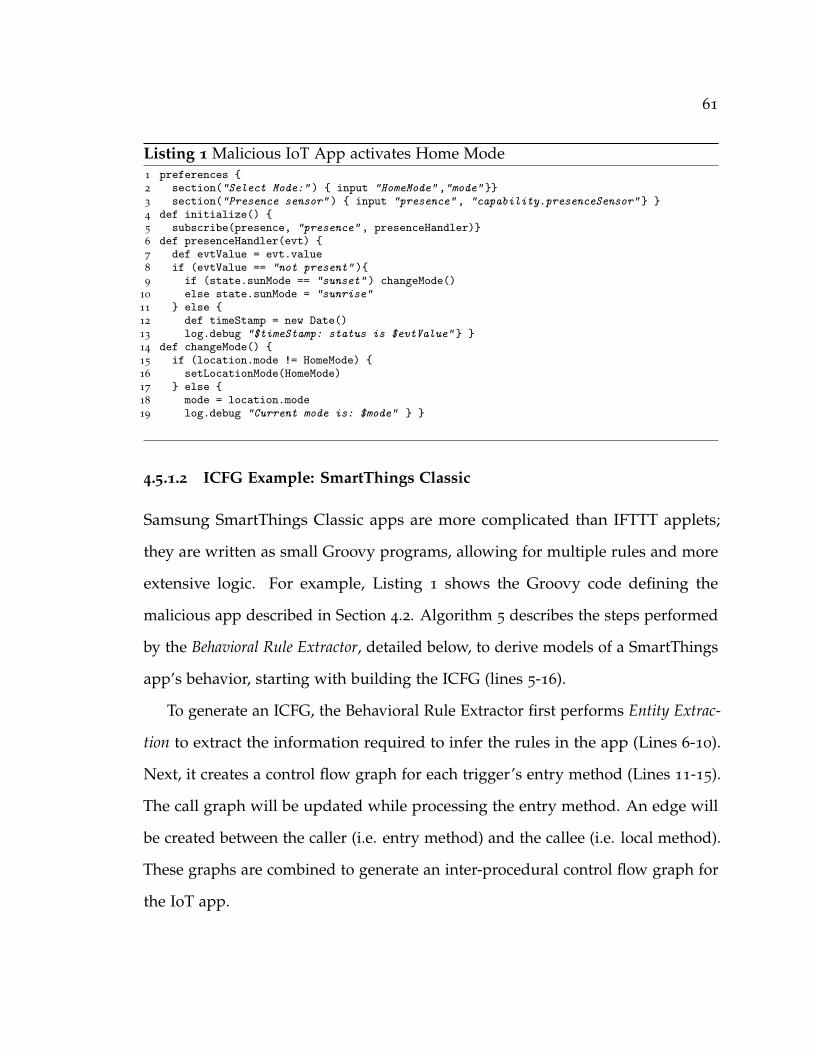
61
Listing 1 Malicious IoT App activates Home Mode1 preferences {2 section("Select Mode:" ) { input "HomeMode" ,"mode" }}3 section("Presence sensor" ) { input "presence" , "capability.presenceSensor" } }4 def initialize() {5 subscribe(presence, "presence" , presenceHandler)}6 def presenceHandler(evt) {7 def evtValue = evt.value8 if (evtValue == "not present" ){9 if (state.sunMode == "sunset" ) changeMode()
10 else state.sunMode = "sunrise"11 } else {12 def timeStamp = new Date()13 log.debug "$timeStamp: status is $evtValue" } }14 def changeMode() {15 if (location.mode != HomeMode) {16 setLocationMode(HomeMode)17 } else {18 mode = location.mode19 log.debug "Current mode is: $mode" } }
4.5.1.2 ICFG Example: SmartThings Classic
Samsung SmartThings Classic apps are more complicated than IFTTT applets;
they are written as small Groovy programs, allowing for multiple rules and more
extensive logic. For example, Listing 1 shows the Groovy code defining the
malicious app described in Section 4.2. Algorithm 5 describes the steps performed
by the Behavioral Rule Extractor, detailed below, to derive models of a SmartThings
app’s behavior, starting with building the ICFG (lines 5-16).
To generate an ICFG, the Behavioral Rule Extractor first performs Entity Extrac-
tion to extract the information required to infer the rules in the app (Lines 6-10).
Next, it creates a control flow graph for each trigger’s entry method (Lines 11-15).
The call graph will be updated while processing the entry method. An edge will
be created between the caller (i.e. entry method) and the callee (i.e. local method).
These graphs are combined to generate an inter-procedural control flow graph for
the IoT app.

62
Algorithm 5 Behavioral Rule Extractor
INPUT: IoT AppOUTPUT: App: set of behavioral rules
1: App← < {} >2: ICFG← {}, CFGs← {}, CG← {}, BRG← {}3: DevicesCap← {}, Triggers← {}4: UserInput← {}, GlobalVar← {}5: // Step 1 : Generating ICFG6: // Step 1.1: Entity Extraction7: DevicesCap← extractDevicesCap(app)8: UserInput← extractUserInput(app)9: GlobalVar← extractGlobalVar(app)
10: Triggers← extractTriggers(app)11: // Step 1.2: Generating ICFG12: for each trigger ∈ Triggers do13: CFGs← constructCFG(trigger.entryMethod)14: CG← updateCG()15: end for16: ICFG← constructICFG(CG, CFGs)17: // Step 2: Converting ICFG to BRG18: BRG← constructBRG (ICFG, Triggers, DevicesCap,19: UserInput, GlobalVar)20: // Step 3: Generating Behavioral Rules21: for each trigger ∈ Triggers do22: App.R← constructRules(BRG)23: end for
Entity Extraction: The first subcomponent determines the entities on which the
app operates, including: (1) the smart home devices and attributes altered/queried
by this app; (2) any configuration values specified by the user, such as a desired
setting for some device attributes; (3) any global variables used in the app; and
(4) any events that trigger actions from the app, signified by use of certain APIs,
and the methods invoked by those triggers.
The extraction algorithm traverses all statements in the AST, extracting the
attached devices and user input from the preferences block (Listing 1, lines 1-10).
Global variables are extracted based on the official SmartThings documentation [37].

63
Certain pre-defined values are assumed to be global, such as the state variable
used on line 21 of Listing 1. We identify all the uses of these global variables.
IoT apps are event-driven, so each subscription or scheduled call defines a
distinct entry point. Triggers and entry methods are thus extracted by traversing
the AST for calls to the subscribe, schedule, runIn, or runOnce API methods. For
instance, a contact sensor device—identified in SmartThings by the contactSensor
capability [100]—has a contact attribute representing the state of the sensor.
The attribute can take two values, either open or closed. Depending on the
value, such a device can be formalized as 〈contactSensor, contact, closed〉, or
〈contactSensor, contact, open〉. The extracted tuples are stored for later use in
building the behavioral rule graph.
Generating ICFG: In conjunction with Entity Extraction, the Behavioral Rule
Extractor also generates a call graph and control flow graph for each user-defined
method using a path-sensitive analysis. To construct an ICFG, each control flow
graph is incorporated with the call graph at each trigger’s entry point. Figure 4.4a
shows the ICFG corresponding to the malicious app code shown in Listing 1. The
ICFG mode includes the CFG of the entry method presenceHandler (Figure 4.4a
left side), and the CFG of the local method changeMode (Figure 4.4a right side).
Note that existing state-of-the-art analysis techniques lack support for direct
program analysis of Groovy code. By performing the analysis directly on the
Groovy code, IotCom avoids the pitfalls (and cost) of translating the code into
some intermediate representation.
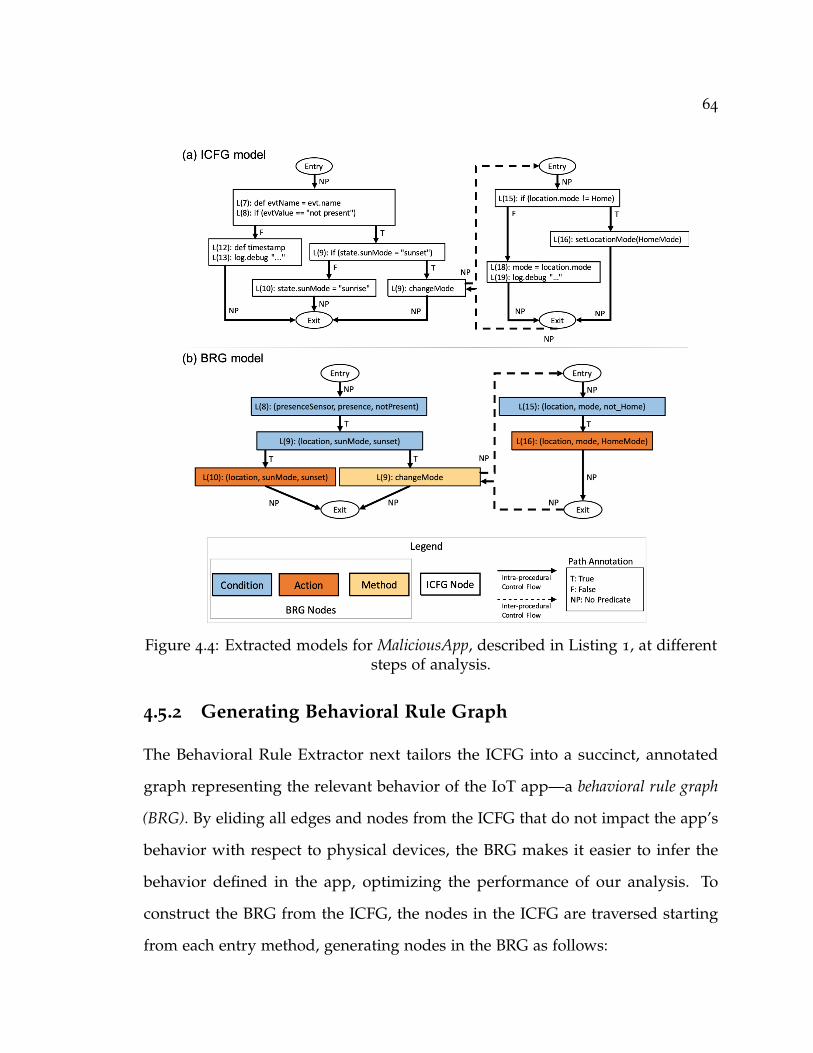
64
Figure 4.4: Extracted models for MaliciousApp, described in Listing 1, at differentsteps of analysis.
4.5.2 Generating Behavioral Rule Graph
The Behavioral Rule Extractor next tailors the ICFG into a succinct, annotated
graph representing the relevant behavior of the IoT app—a behavioral rule graph
(BRG). By eliding all edges and nodes from the ICFG that do not impact the app’s
behavior with respect to physical devices, the BRG makes it easier to infer the
behavior defined in the app, optimizing the performance of our analysis. To
construct the BRG from the ICFG, the nodes in the ICFG are traversed starting
from each entry method, generating nodes in the BRG as follows:
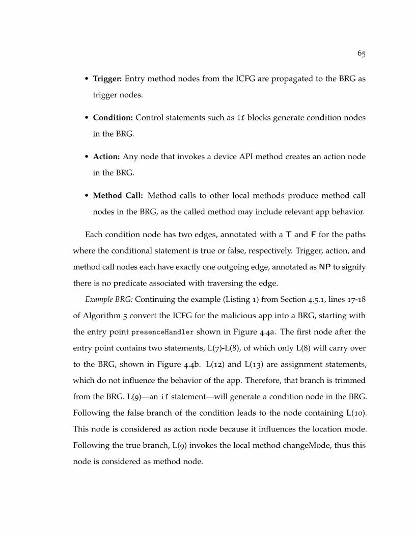
65
• Trigger: Entry method nodes from the ICFG are propagated to the BRG as
trigger nodes.
• Condition: Control statements such as if blocks generate condition nodes
in the BRG.
• Action: Any node that invokes a device API method creates an action node
in the BRG.
• Method Call: Method calls to other local methods produce method call
nodes in the BRG, as the called method may include relevant app behavior.
Each condition node has two edges, annotated with a T and F for the paths
where the conditional statement is true or false, respectively. Trigger, action, and
method call nodes each have exactly one outgoing edge, annotated as NP to signify
there is no predicate associated with traversing the edge.
Example BRG: Continuing the example (Listing 1) from Section 4.5.1, lines 17-18
of Algorithm 5 convert the ICFG for the malicious app into a BRG, starting with
the entry point presenceHandler shown in Figure 4.4a. The first node after the
entry point contains two statements, L(7)-L(8), of which only L(8) will carry over
to the BRG, shown in Figure 4.4b. L(12) and L(13) are assignment statements,
which do not influence the behavior of the app. Therefore, that branch is trimmed
from the BRG. L(9)—an if statement—will generate a condition node in the BRG.
Following the false branch of the condition leads to the node containing L(10).
This node is considered as action node because it influences the location mode.
Following the true branch, L(9) invokes the local method changeMode, thus this
node is considered as method node.
66
After creating the BRG, the statements corresponding to each node are con-
verted to 〈device, attribute, value〉 tuples. If a value in any of the nodes does
not correspond directly to a member of one of those sets, we perform backward
inter-procedural data flow analysis [149] to resolve the dependency. Recall that the
BRG captures all actions that affect sensors and actuators deployed in the smart
home environment. All other details within the scope of the method are discarded.
Furthermore, the edges maintain the control flow that reflects predicates required
to activate a certain action.
4.5.3 Generating Rule Models
The final component of the Behavioral Rule Extractor generates formal models of
each app’s rules based on the BRG. As described in Section 4.1, the behavior of an
IoT app consists of a set of rules R, where each rule is a tuple of triggers, conditions,
and actions, R = 〈T , C, A〉. This behavioral model follows the automation model
in Fig. 4.1, where:
• T is a set of events that trigger specific rules. These events can be timed
events, sensor/actuator notifications, or events directly triggered by the user.
• C is a set of conditions for executing specific rules, based on information
about the state of the cyber and physical components of the system. This
state information may originate from many sources—user configuration or
input, the physical state of devices in the system, environmental values
such as sunrise time—and are general represented as variables in the rule’s
programmatic control flow path or as global user configuration values.
67
• A is a set of actions that can be performed upon execution of a rule. The al-
lowed actions are assumed to be exposed by the actuator proxies in the smart
home framework software, such as the capabilities exposed by SmartThings
to represent the behavior of their supported devices [100].
• Each rule r ∈ R has a set of Triggers(r) ⊆ T, a set of Conditions(r) ⊆ C,
and a set of Actions(r) ⊆ A that define its behavior.
In order to tie the behavior of these rules back to the physical devices in the
smart home, the elements of T, C, and A are each formalized as sets of tuples
of 〈device, attribute, value〉. Each type of device is assumed to have its own
set of device-specific attributes, and each attribute constrains its own allowed
values according to the device manufacturer’s specifications. For example, a
smart lock device may have a “locked” attribute to indicate the state of the
lock, which accepts values of “locked” or “unlocked”. An action to unlock a
specific lock (TheLock) would contain a tuple composed of those elements, e.g.,
〈TheLock, locked, unlocked〉.
To generate the models from the BRG, IotCom starts from each trigger node
(which is used as the Trigger for the rule) and traverses the graph to find the
action nodes; every rule must have at least one Action. From each action node, it
performs a reverse depth-first search back to the trigger, collecting the tuples for
each condition node encountered along the path as the Conditions of the rule.
Since the BRG provides an abstraction of the app’s behavior independent of
the underlying framework, the process would be the same for both IFTTT and
SmartThings Classic.
68
4.6 Formal Analyzer
This section describes the Formal Analyzer component of IotCom, which takes as
input the behavioral rule models generated by the Behavioral Rule Extractor. These
formal models are verified against various safety and security properties using
a bounded model checker, i.e., the Alloy analyzer [150], to exhaustively explore
every interaction within a defined scope. This allows IotCom to automatically
analyze each bundle of apps without manual specification of the initial system
configuration, which is required for comparable state-of-the-art techniques [34, 35].
We use Alloy to demonstrate our approach because it combines a concise, simple
specification language with a fully-automated analyzer capable of exhaustively
checking our models for safety and security violations. In particular, Alloy in-
cludes support for checking transitive closure, which is important to analyze more
complex, chained interactions.
The bounded model checking uses three sets of formal specifications, as shown
in Figure 4.3: (1) a base smart home model describing the general entities composing
a smart home environment; (2) the app-specific behavioral rule models generated by
the Behavioral Rule Extractor; and (3) formal assertions for our safety and security
properties. Complete Alloy models are available online at our project site [151].
4.6.1 Smart Home Model
The overall smart home system is modeled as a set of Devices and a set of IoTApps,
as shown in Listing 2. Each IoTApp contains its own set of Rules. Each Device has
some associated state Attributes, each of which can assume one of a disjoint set of
Values. Recall from Section 4.4, each rule contains its own set of Triggers, Conditions,
and Actions. Each individual trigger, condition, and action is modeled as a tuple of

69
one or more Devices, the relevant Attribute for that type of device, and one or more
Values that are of interest to the trigger, condition, or action. Defined in Alloy, each
of the listed entities is an abstract signature which is extended to a concrete model
signature for each specific type of device, attribute, value, IoT app, behavioral rule,
etc.
Listing 2 Excerpt of base smart home Alloy model.1 abstract sig Device { attributes : set Attribute }2 abstract sig Attribute { values : set Value }3 abstract sig Value { }4 abstract sig IoTApp { rules : set Rule }5 abstract sig Rule {6 triggers : set Trigger,7 conditions : set Condition,8 actions : some Action }9 // Trigger, Condition, and Action contain
10 // similar tuples11 abstract sig Trigger {12 devices : some Device,13 attribute : one Attribute,14 values : set Value }15 abstract sig Condition { ... }16 abstract sig Action { ... }
Apps can communicate both virtually within the cloud backend and physically
via the devices they control. Virtual interactions fall into two main categories: (1)
direct mappings, where one app triggers another by acting directly on a virtual
device/variable watched by the triggered app; or (2) scheduling, where one rule
calls (e.g.) the runIn API from SmartThings to invoke a second rule after a delay.
Physically mediated interactions occur indirectly via some physical channel, such
as temperature. Our model—in contrast to others [34]—directly supports detection
of violations mediated via physical channels. As part of our model of the overall
SmartThings ecosystem, we include a mapping of each device to one or more
physical Channels as either a sensor or an actuator (not shown in Listing 2).
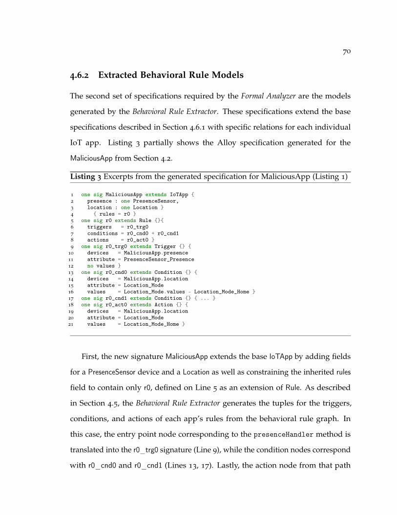
70
4.6.2 Extracted Behavioral Rule Models
The second set of specifications required by the Formal Analyzer are the models
generated by the Behavioral Rule Extractor. These specifications extend the base
specifications described in Section 4.6.1 with specific relations for each individual
IoT app. Listing 3 partially shows the Alloy specification generated for the
MaliciousApp from Section 4.2.
Listing 3 Excerpts from the generated specification for MaliciousApp (Listing 1)
1 one sig MaliciousApp extends IoTApp {2 presence : one PresenceSensor,3 location : one Location }4 { rules = r0 }5 one sig r0 extends Rule {}{6 triggers = r0_trg07 conditions = r0_cnd0 + r0_cnd18 actions = r0_act0 }9 one sig r0_trg0 extends Trigger {} {
10 devices = MaliciousApp.presence11 attribute = PresenceSensor_Presence12 no values }13 one sig r0_cnd0 extends Condition {} {14 devices = MaliciousApp.location15 attribute = Location_Mode16 values = Location_Mode.values - Location_Mode_Home }17 one sig r0_cnd1 extends Condition {} { ... }18 one sig r0_act0 extends Action {} {19 devices = MaliciousApp.location20 attribute = Location_Mode21 values = Location_Mode_Home }
First, the new signature MaliciousApp extends the base IoTApp by adding fields
for a PresenceSensor device and a Location as well as constraining the inherited rules
field to contain only r0, defined on Line 5 as an extension of Rule. As described
in Section 4.5, the Behavioral Rule Extractor generates the tuples for the triggers,
conditions, and actions of each app’s rules from the behavioral rule graph. In
this case, the entry point node corresponding to the presenceHandler method is
translated into the r0_trg0 signature (Line 9), while the condition nodes correspond
with r0_cnd0 and r0_cnd1 (Lines 13, 17). Lastly, the action node from that path

71
of the BRG generates r0_act0 (Line 18). Each of the apps analyzed would be
translated into a similar specification; the bundle of these specifications define all
apps in the system, analyzed by the bounded model checker.
4.6.3 Safety/Security Properties
Figure 4.5: Counterexample from Alloy for running example.
To provide a basis for precise analysis of IoT app bundles against safety and
security violations and further to automatically identify possible scenarios of their

72
Listing 4 Example Alloy assertion for property G3.12.
1 assert G3_12 {2 no r : IoTApp.rules, a : r.actions {3 // DON'T open the door...4 a.attribute = CONTACT_SENSOR_CONTACT_ATTR5 a.values = CONTACT_SENSOR_OPEN6 // ... WHEN ...7 ((some r' : r.*are_connected, t : r'.triggers {8 // ...smoke is detected9 t.attribute = SMOKE_DETECTOR_SMOKE_ATTR
10 t.values = SMOKE_DETECTOR_IS_SMOKE }) or11 (some r' : r.*are_connected, a' : r'.actions {12 // ...mode is away13 a'.attribute = MODE_ATTR14 a'.values = MODE_AWAY })) }}
occurrences given particular conditions of each bundle, we designed specific Alloy
assertions. These assertions express properties that are expected to hold in the
extracted specifications. Specifically, each assertion captures a specific type of
safety and security properties, considering our safety goals for IoT app interactions
(cf. Section 4.3). In total, we define 36 safety properties, as summarized in Table 4.1.
The property check is then formulated as a problem of finding a valid trace
that satisfies the specifications, yet violating the assertion. The returned solution
encodes an exact scenario (states of all elements, such as Devices) leading to the
violation.
As a concrete example, Listing 4 formally expresses property G3.12 from
Table 4.1. The assertion states that no rule (r) should have an action (a, Line 2) that
results in a contact sensor (i.e., the door) being opened (Lines 4-5) while also being
connected to another rule (r’) that either (1) was triggered by the smoke detector
(Lines 7-10) or (2) sets the home mode to Away (Lines 11-14). If Alloy can find a
trace containing such an r and r’, that trace will be presented as a counterexample,
along with the information useful in finding the root cause of the violation. Given
our running example, the analyzer automatically generates the counterexample
73
depicted in Figure 4.5. The rule FireAlarmApp/r0 (thick border) violates the assertion
by opening the contact sensor (i.e., door) despite its connection to rules higher in
the chain that were (1) triggered by the smoke detector (FireAlarmApp/r1) and (2)
set the home mode to Away (MaliciousApp/r0).
Our ability to detect violations in complex chains of interaction across both
cyber and physical channels sets our work apart from other research in the area,
as does our ability to analyze the conditional predicates of each rule.
4.7 Evaluation
This section presents our experimental evaluation of IotCom, addressing the
following research questions:
• RQ1: What is the overall accuracy of IotCom in identifying safety and
security violations compared to other state-of-the-art techniques?
• RQ2: How well does IotCom perform in practice? Can it find safety and
security violations in real-world apps?
• RQ3: What is the performance of IotCom’s analysis realized atop static
analysis and verification technologies?
Experimental subjects. Our experiments are all run on a multi-platform dataset
of smart home apps drawn from two sources: (1) SmartThings apps: We gathered
404 SmartThings Classic apps from the SmartThings public repository [152]. These
apps are written in Groovy using the SmartThings Classic API platform. (2) IFTTT
Applets: We used the IFTTT dataset provided by Bastys et al. [76]. This dataset is
in JSON format, with each object defining an IFTTT applet. These applets cover
74
a broad spectrum of services, so we filtered the dataset to extract the 55 applets
specifically related to SmartThings.
Safety and Security Properties. We use a set of 36 safety and security proper-
ties for all of our experiments, each encoded as an Alloy assertion as described
in Section 4.6.3. Table 4.1 defines the property set, grouped according to the
corresponding goal from Section 4.3. To preserve the validity of our research,
we adapted these properties from those used by other approaches in the lit-
erature [34, 35, 36, 78]. Some of these properties are general, considering the
interaction between rules with no regard to specific triggers, conditions, or actions.
For example, (G1.1) NO repeated actions considers a case where two apps both send
the same command to the same device in response to a single event. Repeated
actions could force the device to activate multiple times, increasing wear on the
device and violating the very definition of our goal.
Others are more system- or situation-specific, such as (G3.12) DON’T open the
door WHEN smoke is detected or mode is away. The majority of such situation-specific
properties consider the values for the various state attributes of each device in the
system and tend to collect under (G3) No unsafe states.
We performed all the experiments on a MacBook Pro with a 2.2GHz 2-core
Intel i7 processor and 16GB RAM. We used Alloy 4.2 for model checking.
4.7.1 Results for RQ1 (Accuracy)
To evaluate the effectiveness and accuracy of IotCom and compare it against other
state-of-the-art techniques, we used the IoTMAL [153] suite of benchmarks. This
dataset contains custom SmartThings Classic apps, for which all violations, either
singly or in groups, are known in advance—establishing a ground truth.
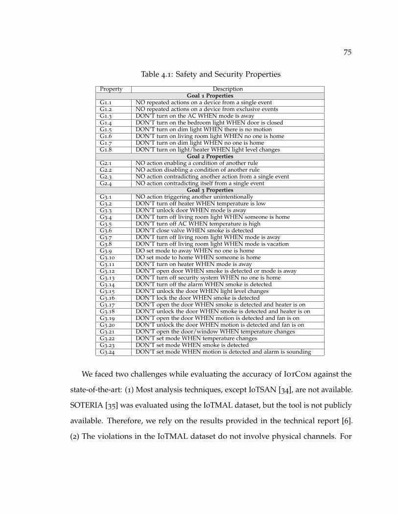
75
Table 4.1: Safety and Security Properties
Property DescriptionGoal 1 Properties
G1.1 NO repeated actions on a device from a single eventG1.2 NO repeated actions on a device from exclusive eventsG1.3 DON’T turn on the AC WHEN mode is awayG1.4 DON’T turn on the bedroom light WHEN door is closedG1.5 DON’T turn on dim light WHEN there is no motionG1.6 DON’T turn on living room light WHEN no one is homeG1.7 DON’T turn on dim light WHEN no one is homeG1.8 DON’T turn on light/heater WHEN light level changes
Goal 2 PropertiesG2.1 NO action enabling a condition of another ruleG2.2 NO action disabling a condition of another ruleG2.3 NO action contradicting another action from a single eventG2.4 NO action contradicting itself from a single event
Goal 3 PropertiesG3.1 NO action triggering another unintentionallyG3.2 DON’T turn off heater WHEN temperature is lowG3.3 DON’T unlock door WHEN mode is awayG3.4 DON’T turn off living room light WHEN someone is homeG3.5 DON’T turn off AC WHEN temperature is highG3.6 DON’T close valve WHEN smoke is detectedG3.7 DON’T turn off living room light WHEN mode is awayG3.8 DON’T turn off living room light WHEN mode is vacationG3.9 DO set mode to away WHEN no one is homeG3.10 DO set mode to home WHEN someone is homeG3.11 DON’T turn on heater WHEN mode is awayG3.12 DON’T open door WHEN smoke is detected or mode is awayG3.13 DON’T turn off security system WHEN no one is homeG3.14 DON’T turn off the alarm WHEN smoke is detectedG3.15 DON’T unlock the door WHEN light level changesG3.16 DON’T lock the door WHEN smoke is detectedG3.17 DON’T open the door WHEN smoke is detected and heater is onG3.18 DON’T unlock the door WHEN smoke is detected and heater is onG3.19 DON’T open the door WHEN motion is detected and fan is onG3.20 DON’T unlock the door WHEN motion is detected and fan is onG3.21 DON’T open the door/window WHEN temperature changesG3.22 DON’T set mode WHEN temperature changesG3.23 DON’T set mode WHEN smoke is detectedG3.24 DON’T set mode WHEN motion is detected and alarm is sounding
We faced two challenges while evaluating the accuracy of IotCom against the
state-of-the-art: (1) Most analysis techniques, except IoTSAN [34], are not available.
SOTERIA [35] was evaluated using the IoTMAL dataset, but the tool is not publicly
available. Therefore, we rely on the results provided in the technical report [6].
(2) The violations in the IoTMAL dataset do not involve physical channels. For
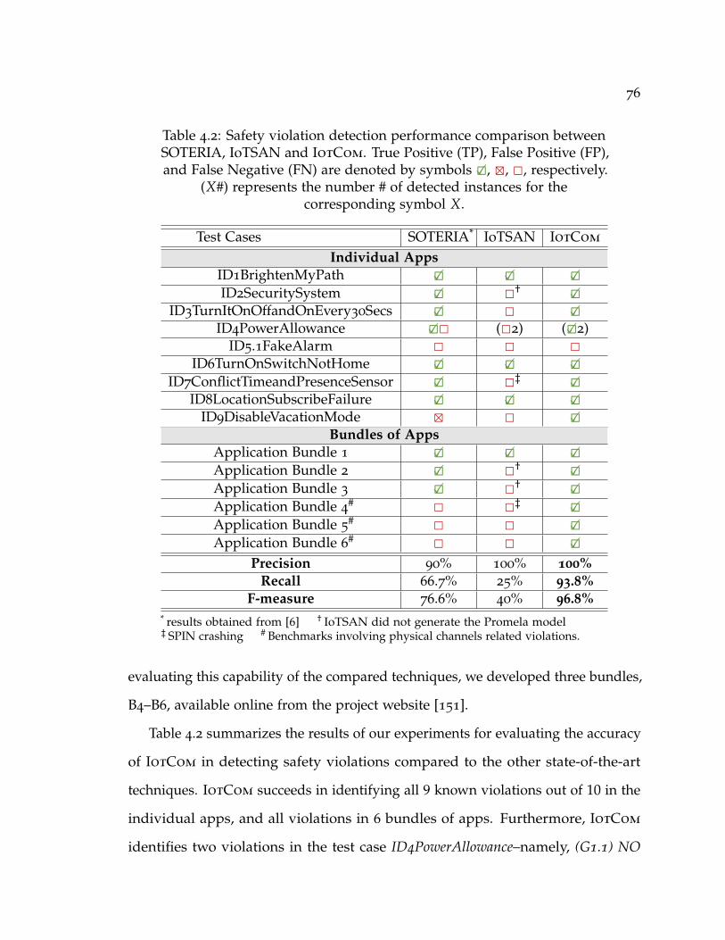
76
Table 4.2: Safety violation detection performance comparison betweenSOTERIA, IoTSAN and IotCom. True Positive (TP), False Positive (FP),and False Negative (FN) are denoted by symbols 2�, 4, 2, respectively.
(X#) represents the number # of detected instances for thecorresponding symbol X.
Test Cases SOTERIA* IoTSAN IotCom
Individual AppsID1BrightenMyPath 2� 2� 2�ID2SecuritySystem 2� 2† 2�
ID3TurnItOnOffandOnEvery30Secs 2� 2 2�ID4PowerAllowance 2�2 (22) (2�2)
ID5.1FakeAlarm 2 2 2ID6TurnOnSwitchNotHome 2� 2� 2�
ID7ConflictTimeandPresenceSensor 2� 2‡ 2�ID8LocationSubscribeFailure 2� 2� 2�
ID9DisableVacationMode 4 2 2�Bundles of Apps
Application Bundle 1 2� 2� 2�Application Bundle 2 2� 2† 2�Application Bundle 3 2� 2† 2�Application Bundle 4
# 2 2‡ 2�Application Bundle 5
# 2 2 2�Application Bundle 6
# 2 2 2�Precision 90% 100% 100%
Recall 66.7% 25% 93.8%F-measure 76.6% 40% 96.8%
* results obtained from [6] † IoTSAN did not generate the Promela model‡ SPIN crashing # Benchmarks involving physical channels related violations.
evaluating this capability of the compared techniques, we developed three bundles,
B4–B6, available online from the project website [151].
Table 4.2 summarizes the results of our experiments for evaluating the accuracy
of IotCom in detecting safety violations compared to the other state-of-the-art
techniques. IotCom succeeds in identifying all 9 known violations out of 10 in the
individual apps, and all violations in 6 bundles of apps. Furthermore, IotCom
identifies two violations in the test case ID4PowerAllowance–namely, (G1.1) NO
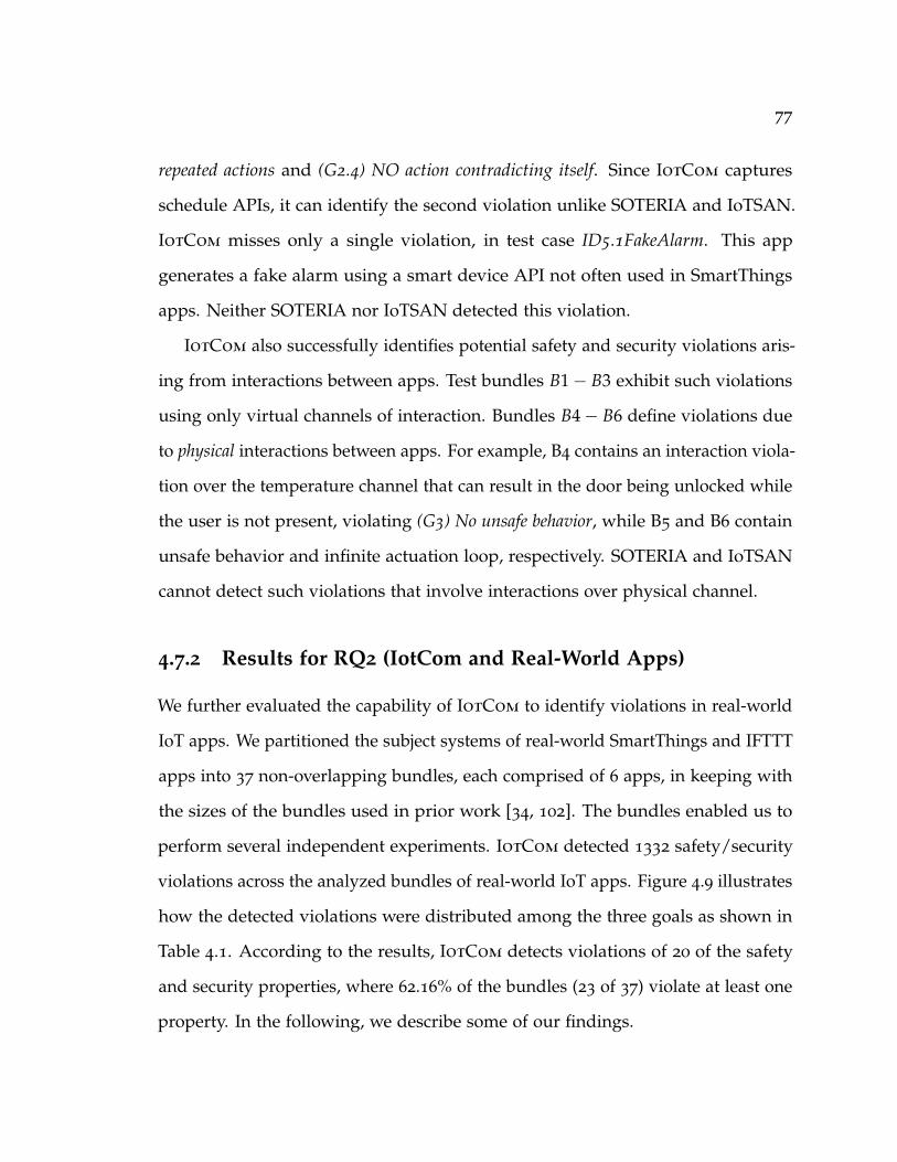
77
repeated actions and (G2.4) NO action contradicting itself. Since IotCom captures
schedule APIs, it can identify the second violation unlike SOTERIA and IoTSAN.
IotCom misses only a single violation, in test case ID5.1FakeAlarm. This app
generates a fake alarm using a smart device API not often used in SmartThings
apps. Neither SOTERIA nor IoTSAN detected this violation.
IotCom also successfully identifies potential safety and security violations aris-
ing from interactions between apps. Test bundles B1− B3 exhibit such violations
using only virtual channels of interaction. Bundles B4− B6 define violations due
to physical interactions between apps. For example, B4 contains an interaction viola-
tion over the temperature channel that can result in the door being unlocked while
the user is not present, violating (G3) No unsafe behavior, while B5 and B6 contain
unsafe behavior and infinite actuation loop, respectively. SOTERIA and IoTSAN
cannot detect such violations that involve interactions over physical channel.
4.7.2 Results for RQ2 (IotCom and Real-World Apps)
We further evaluated the capability of IotCom to identify violations in real-world
IoT apps. We partitioned the subject systems of real-world SmartThings and IFTTT
apps into 37 non-overlapping bundles, each comprised of 6 apps, in keeping with
the sizes of the bundles used in prior work [34, 102]. The bundles enabled us to
perform several independent experiments. IotCom detected 1332 safety/security
violations across the analyzed bundles of real-world IoT apps. Figure 4.9 illustrates
how the detected violations were distributed among the three goals as shown in
Table 4.1. According to the results, IotCom detects violations of 20 of the safety
and security properties, where 62.16% of the bundles (23 of 37) violate at least one
property. In the following, we describe some of our findings.
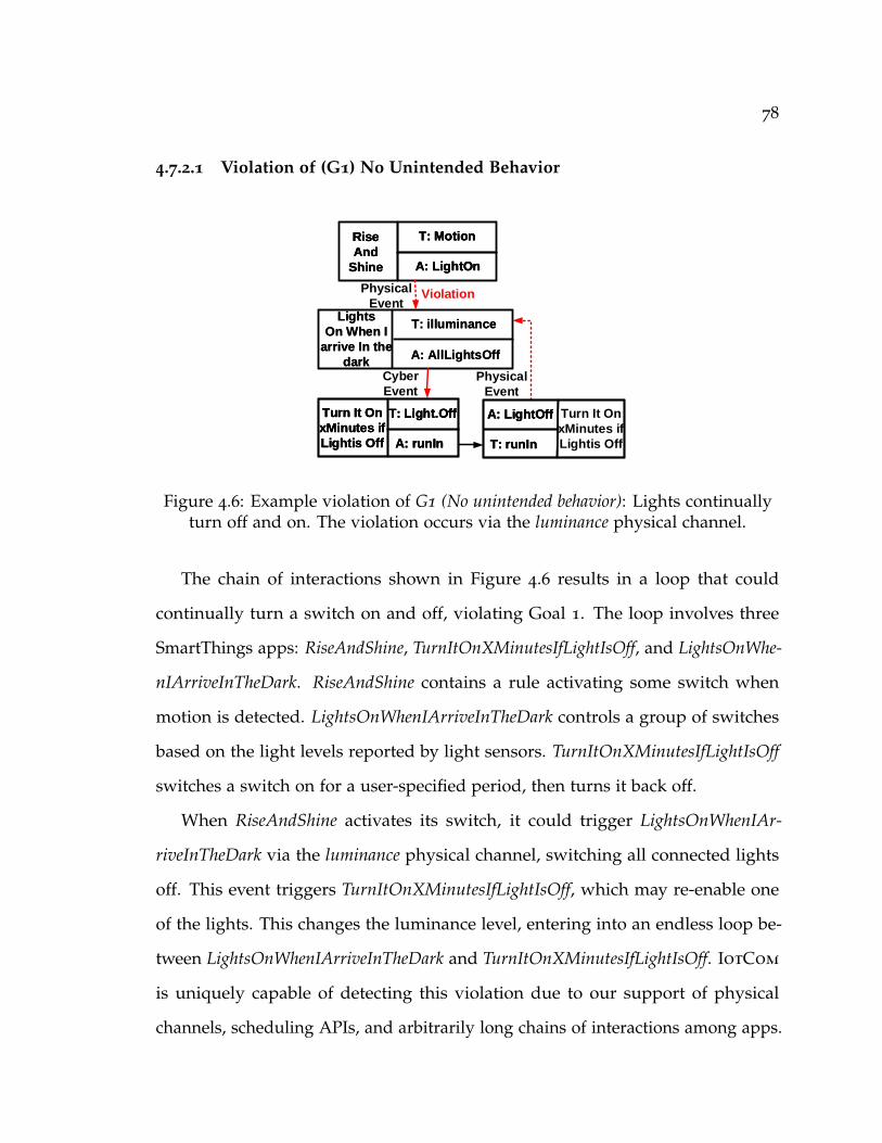
78
4.7.2.1 Violation of (G1) No Unintended Behavior
T: illuminance
A: AllLightsOff
Lights
On When I
arrive In the
dark
T: illuminance
A: AllLightsOff
Lights
On When I
arrive In the
dark
Violation
T: Motion
A: LightOn
Rise
And
Shine
T: Motion
A: LightOn
Rise
And
Shine
T: Motion
A: LightOn
Rise
And
Shine
T: runIn
A: LightOff
T: runIn
A: LightOff
T: runIn
A: LightOff
Cyber
Event
Physical
Event
T: Light.Off
A: runIn
Turn It On
xMinutes if
Lightis Off
T: Light.Off
A: runIn
Turn It On
xMinutes if
Lightis Off
T: Light.Off
A: runIn
Turn It On
xMinutes if
Lightis Off
Turn It On
xMinutes if
Lightis Off
Physical
Event
Figure 4.6: Example violation of G1 (No unintended behavior): Lights continuallyturn off and on. The violation occurs via the luminance physical channel.
The chain of interactions shown in Figure 4.6 results in a loop that could
continually turn a switch on and off, violating Goal 1. The loop involves three
SmartThings apps: RiseAndShine, TurnItOnXMinutesIfLightIsOff, and LightsOnWhe-
nIArriveInTheDark. RiseAndShine contains a rule activating some switch when
motion is detected. LightsOnWhenIArriveInTheDark controls a group of switches
based on the light levels reported by light sensors. TurnItOnXMinutesIfLightIsOff
switches a switch on for a user-specified period, then turns it back off.
When RiseAndShine activates its switch, it could trigger LightsOnWhenIAr-
riveInTheDark via the luminance physical channel, switching all connected lights
off. This event triggers TurnItOnXMinutesIfLightIsOff, which may re-enable one
of the lights. This changes the luminance level, entering into an endless loop be-
tween LightsOnWhenIArriveInTheDark and TurnItOnXMinutesIfLightIsOff. IotCom
is uniquely capable of detecting this violation due to our support of physical
channels, scheduling APIs, and arbitrarily long chains of interactions among apps.
79
4.7.2.2 Violation of (G2) No Unpredictable Behavior
T: DoorOpen
A: LightOn
Garage
door
notification
T: DoorOpen
A: LightOn
Garage
door
notification
T: LightOn
A: LightOff
TurnItOff
After
T: LightOn
A: LightOff
TurnItOff
After
T: Illuminance
A: LightOn
Light
wars
on
T: Illuminance
A: LightOn
Light
wars
on
Physical
Event
Cyber
Event
Conflict
Figure 4.7: Example violation of (G2) No unpredictable behavior: Both “on” and “off”commands sent to the same light due to the same event. The violation happens
via the luminance physical channel.
The three apps shown in Figure 4.7 lead to potentially unpredictable behavior
due to competing commands to the same device, violating Goal 2. They also
interact in part over a physical channel that could not be detected by approaches
that only consider virtual interaction between apps. The IFTTT applet Garage-
DoorNotification activates a switch when the garage door is opened. This triggers
the action of SmartThings app TurnItOffAfter, which will turn off the light after
a predefined period. At the same time, GarageDoorNotification may also have
triggered the IFTTT applet LightWarsOn via a light sensor, interacting over the
physical luminance channel. LightWarsOn would attempt to turn the light back on,
producing an unpredictable result—a race condition—depending on which rule
was executed first.
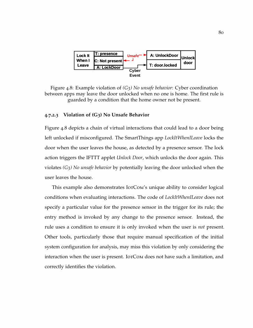
80
T: presence
C: Not present
A: LockDoor
Lock It
When I
Leave
T: presence
C: Not present
A: LockDoor
Lock It
When I
Leave T: door.locked
A: UnlockDoorUnlock
doorT: door.locked
A: UnlockDoorUnlock
door
Unsafe
Cyber
Event
Figure 4.8: Example violation of (G3) No unsafe behavior: Cyber coordinationbetween apps may leave the door unlocked when no one is home. The first rule is
guarded by a condition that the home owner not be present.
4.7.2.3 Violation of (G3) No Unsafe Behavior
Figure 4.8 depicts a chain of virtual interactions that could lead to a door being
left unlocked if misconfigured. The SmartThings app LockItWhenILeave locks the
door when the user leaves the house, as detected by a presence sensor. The lock
action triggers the IFTTT applet Unlock Door, which unlocks the door again. This
violates (G3) No unsafe behavior by potentially leaving the door unlocked when the
user leaves the house.
This example also demonstrates IotCom’s unique ability to consider logical
conditions when evaluating interactions. The code of LockItWhenILeave does not
specify a particular value for the presence sensor in the trigger for its rule; the
entry method is invoked by any change to the presence sensor. Instead, the
rule uses a condition to ensure it is only invoked when the user is not present.
Other tools, particularly those that require manual specification of the initial
system configuration for analysis, may miss this violation by only considering the
interaction when the user is present. IotCom does not have such a limitation, and
correctly identifies the violation.

81
4.7.3 Results for RQ3 (Performance and Timing)
The last evaluation criteria are the performance benchmarks of static model ex-
traction and formal analysis of IotCom on real-world apps drawn from the Smart-
Things and IFTTT repositories.
Figure 4.10 presents the time taken by IotCom to extract rule models from the
Groovy SmartThings apps and IFTTT applets. This measurement is done on the
datasets collected from two repositories: 404 SmartThings apps drawn from the
SmartThings public repository [152] and 55 IFTTT applets from the dataset used
by Bastys et al. [76]. The scatter plot shows both the analysis time and the app
size. According to the results, our approach statically analyzes 98% of apps in
less than one second. As our approach for model extraction analyzes each app
independently, the total static analysis time scales linearly with the number of
apps.
Figure 4.9: Distribution of detection violations across three goals (cf. Section 4.3).
We also measured the verification time required for detecting safety/security
violations and compared the analysis time of IotCom against that required by
IoTSAN [34]. We checked all 36 safety and security properties against each bundle.
Based on our results, the time required by the Formal Analyzer scales based on
the number of rules per bundle rather than the number of apps. This is to be

82
00.20.40.60.8
11.21.4
0 100 200 300 400 500 600 700
Tim
e (s
econ
d)
LOC
Groovy SmartThings IFTTT
Figure 4.10: Scatter plot representing analysis time for behavioral rule extractionof IoT apps using IotCom.
Figure 4.11: Average time required to analyze all properties related to each goal bynumber of rules in the analyzed bundle.
expected, given that our analysis compares fine-grained rule-to-rule interaction.
Nguyen et al. [34] manually specify the initial configuration for each app in
the bundle as part of the model checked by IoTSAN; IotCom does not require
specification of a single initial configuration, instead exhaustively checking all
configurations that fall within the scope of the app model. To perform a fair
comparison between the two approaches, we generated initial configurations for
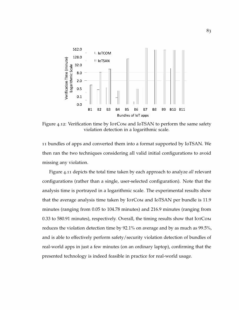
83
Figure 4.12: Verification time by IotCom and IoTSAN to perform the same safetyviolation detection in a logarithmic scale.
11 bundles of apps and converted them into a format supported by IoTSAN. We
then ran the two techniques considering all valid initial configurations to avoid
missing any violation.
Figure 4.11 depicts the total time taken by each approach to analyze all relevant
configurations (rather than a single, user-selected configuration). Note that the
analysis time is portrayed in a logarithmic scale. The experimental results show
that the average analysis time taken by IotCom and IoTSAN per bundle is 11.9
minutes (ranging from 0.05 to 104.78 minutes) and 216.9 minutes (ranging from
0.33 to 580.91 minutes), respectively. Overall, the timing results show that IotCom
reduces the violation detection time by 92.1% on average and by as much as 99.5%,
and is able to effectively perform safety/security violation detection of bundles of
real-world apps in just a few minutes (on an ordinary laptop), confirming that the
presented technology is indeed feasible in practice for real-world usage.

84
4.8 Discussion
IoT apps and devices interact with each other in complex ways. Therefore, a
holistic analysis is crucial to identify safety and security threats that may arise from
multiple such interactions. Celik et al. [6] describe the challenges of analyzing IoT
apps. These include consideration of interactions over physical channels and the
capability to perform cross-platform analysis, which does not limit the analysis to a
single IoT platform (i.e. IFTTT only or Groovy only). Celik et al. also emphasize the
importance of performing a precise program analysis. Accordingly, IotCom has
been designed and implemented to overcome those challenges. IotCom models
each app individually, but composes all the models into a complete picture of the
IoT system to analyze their interactions. Our analysis accounts for interactions
mediated by physical channels, while other approaches focus only on interactions
within the virtual system.
IotCom models time-based APIs (e.g. runIn, sunrise, sunset), but does not
precisely model the relative durations requested in calls to these APIs. Our next
step is to model time more precisely. IotCom does not require initial configurations,
which significantly enhances its capabilities. However, our model does not account
for all variables that could influence the configuration, such as spatial distance
between devices [154]. Also, some SmartThings capabilities—such as switch—are
very general and can be associated with many physical channels. We do not
distinguish between different uses of these general devices. Considering these
additional factors may improve the accuracy.
The novel graph abstraction technique proposed in IotCom makes it practical
for handling on-going and future developments in the domain of IoT apps, like
multiple actions and triggers for conditional triggering [155].
85
4.9 Summary
This chapter presents a novel approach for compositional analysis of IoT interaction
threats. Our approach employs static analysis to automatically derive models that
reflect behavior of IoT apps and interactions among them. The approach then
leverages these models to detect safety and security violations due to interaction of
multiple apps and their embodying physical environment that cannot be detected
with prior techniques that concentrate on interactions within the cyber boundary.
We formalized the principal elements of our analysis in an analyzable specification
language based on relational logic, and developed a prototype implementation,
IotCom, on top of our formal analysis framework. The experimental results of
evaluating IotCom against 36 prominent IoT safety and security properties, in the
context of hundreds of real-world apps, corroborates its ability to effectively detect
violations triggered through both cyber and physical channels.

86
5 Efficient Signature Generation for Classifying
Cross-Architecture IoT Malware
Internet-of-Things (IoT) devices are increasingly targeted by adversaries due to
their unique characteristics such as constant online connection, lack of protection,
and full integration in people’s daily life. As attackers shift their targets towards
IoT devices, malware has been developed to compromise IoT devices equipped
with different CPU architectures. While malware detection has been a well-studied
area for desktop PCs, heterogeneous processor architecture in IoT devices brings
in unique challenges. Existing approaches utilize static or dynamic binary analysis
for identifying malware characteristics, but they all fall short when dealing with
IoT malware compiled for different architectures. In this chapter, we propose an
efficient signature generation method for IoT malware, which generates distin-
guishable signatures based on high-level structural, statistical and string feature
vectors, as high-level features are more robust against code variations across differ-
ent architectures. The generated signatures for each malware family can be used
for developing lightweight malware detection tools to secure IoT devices. Extensive
experiments with two datasets including 5, 150 recent IoT malware samples show
that our scheme can achieve 85.2% detection rate with 0% false positive rate.
87
5.1 Motivation
IoT malware/vulnerability research. The priority of most IoT vendors are func-
tionalities and faster pace of bringing product to market. The security of IoT
systems has not received much attention. The most relevant research focuses
on developing an IoT honeypot [156] called IoTPOT, used to allure malware to
infect emulated IoT devices in the honeypot, which aims at collecting IoT malware
binaries and the corresponding network traffic for further analysis. The malware
binaries have been clustered into four distinct families based on simple command
sequence and unique strings through manual analysis. Yet, they neglect the rich
code-level features that facilitate a fine-grained characterization of IoT malware.
Vulnerability and bug discovery of IoT devices is a problem gaining attentions
recently [157, 158, 159]. Eschweiler et al. [158] utilize graph matching approaches in
conjunction with statistical features extracted from the disassembled binary codes
to detect bugs. However, their goal is to identify similarity between individual
vulnerable functions rather than matching binary files and generating detection
signatures. Recently, Feng et al. [159] employ a scalable search method to improve
the scalability and accuracy of cross-architecture bug search, where both the
structural and statistical features are aggregated to create a high-level feature
vector for vulnerability detection in real-time. All of the above methods use static
analysis to extract features at basic block level using control flow graph (CFG). Yet,
the high computational complexity of processing CFGs hinders their deployment
on IoT devices.
Converting the assembly code to Intermediate Representation (IR) code has
been adopted to handle syntax differences to perform cross-architecture analy-
sis [160]. However, available IR languages/platforms are limited to handle only
88
a few architectures (i.e., MIPS, ARM, x86), which are not suitable for our dataset
that contains malware with more diverse architectures.
IoT malware dataset. Our IoT malware dataset is provided by IoTPOT team,
including two recently-collected datasets: one is collected within a three-month
period between May 2016 and August 2016, and contains 1, 150 malware sam-
ples/binaries; and the other one is collected within a one-year period between
October 2016 to October 2017, containing 4, 000 malware samples/binaries. Every
sample has a MD5 name and a time label. To the best of our knowledge, this IoT
malware dataset is the largest dataset currently available. To date, there are around
7, 000 IoT malware samples targeting smart devices as reported by Kapersky [42].
Therefore, we believe the research on 5, 150 malware set (74% of total amount) can
faithfully reveal the characteristics of most IoT malware. All the malware binaries
are Linux Executable and Linkable Format (ELF) format executable files. Figure 5.1
shows the diverse CPU architectures of the malware samples in our dataset, where
ARM and MIPS are two most popular architectures for IoT malware. The detection
rate of IoT malware is known to be low [161]. Therefore, an accurate and lightweight
cross-architectural detection mechanism that can be deployed on resource-constrained IoT
devices is a pressing need.
Malware statistical, string Features, and string obfuscation/encryption. As men-
tioned earlier, this work aims to develop lightweight IoT malware signatures, which
implies the features used for generating the signatures should be easy to extract,
and also the extracted features can differentiate between malicious and benign
samples. In this work, we consider statistical and string features for clustering
and signature generation of IoT malware families. Table 5.1 presents the statistical
features extracted from exemplar benign and malicious files. It shows a significant
difference between the code statistics features of benign and malicious files.

89
378 378 407 422 456
769
1159 1172
0
200
400
600
800
1000
1200
Num
bero
fSam
ples
Figure 5.1: IoT malware distribution based on CPU types
Files Redirect Arithmetic Logical Transfer TotalBenign-1 108719 23117 41817 300822 647654
Benign-2 129662 25204 57020 371085 767334
Benign-3 166767 36143 64249 487340 1025432
Malicious-1 10434 1744 2085 17087 45831
Malicious-2 13283 2104 2427 22513 58558
Malicious-3 5354 3707 408 363 31843
Table 5.1: Number of instructions for benign and malicious binaries
We also extract printable strings from the malware samples, and discover that
the extracted printable strings of many malware samples contain the same string
sequences, yet, they are compiled for different architectures. For instance, our
experimental results show that the same printable strings such as “busybox iptables
-A INPUT -p tcp –destination-port 7547 -j DROP" appeared in different versions of
Mirai for different architecture types, such as MIPS, ARM, PowerPC and Renesas
SH. This implies that IoT malware is developed to infect multiple architectures.
Also, we observe printable strings contain other rich information that can be
used to distinguish between different malware families (see Section 5.2.3). Such

90
observation and the fact that printable strings are easy to extract motivate us to
consider printable strings for signature generation.
Some printable strings from malware samples are obfuscated or encrypted.
However, we find that the encrypted/obfuscated printable strings of some malware
samples can also be overlapped, if these samples use the same encryption/obfus-
cation mechanisms. For instance, we find many samples from the same malware
family contain the same encrypted/obfuscated sequences “eGAIM aJPMOG qCD-
CPK oMXKNNC uKLFMUQ", which can be used as signatures to identify samples
from the same malware family.
5.2 Signature Generation of IoT Malware
Malware
Preprocessing
Coarse-Grained
Clustering
Fine-Grained
Clustering Cluster Merging
Signature
Generation
Sig1
Sig5
Sig4
Sig2
Sig3
String
Features
Signature Generation System (SGS)
New Malware
Online Detection
Results
Online Detection
System (ODS)
Signature
Generation
Check
Result
Figure 5.2: Detection system architecture
In this section, we present the design of our system that aims to generate
signatures for classifying and detecting IoT malware. The proposed system consists
of two major phases: offline signature generation and online detection/classification. The
offline signature generation takes IoT malware samples as input, which includes
the following five steps, as presented in Fig. 5.2: 1) malware preprocessing, 2)
coarse-grained clustering, 3) fine-grained clustering, 4) cluster merging, and 5)
signature generation for online detection.
91
5.2.1 System Overview
The offline signature generation can be conducted at computationally rich cloud-
s/hubs. The malware preprocessing removes non-binary files from the dataset,
and disassembles all the binary files using IDA Pro [162] to retrieve their assembly
codes. After preprocessing, the number of malware samples is reduced to 4,078.
We propose three stages of clustering, including coarse-grained clustering, fine-
grained clustering, and cluster merging. The coarse-grained clustering utilizes
statistical features, while the fine-grained clustering clusters the malware samples
based on their structural similarities computed using Bindiff. The combination of
coarse-grained and fine-grained clustering allows us to decrease the computational
cost of the clustering process, compared to using only fine-grained clustering.
Cluster merging refines the clustering results by merging clusters based on the
similarity of extracted string features in an iterative manner. The cluster merging
allows us to attain more generic malware signatures, thus improving the malware
detection rate. Finally, we generate a succinct signature by integrating string and
statistical features for each malware cluster, which can distinguish between differ-
ent malware clusters. We use string and statistical features due to their capability
in producing distinguishable patterns and ease of extraction. Online detection/-
classification can be conducted on IoT devices by matching the signatures. In the
following sections, we describe the system components.
5.2.2 Clustering IoT Malware
Instead of operating over each individual malware sample, we cluster these samples
into groups, and perform group-level analysis to reduce the computational costs.
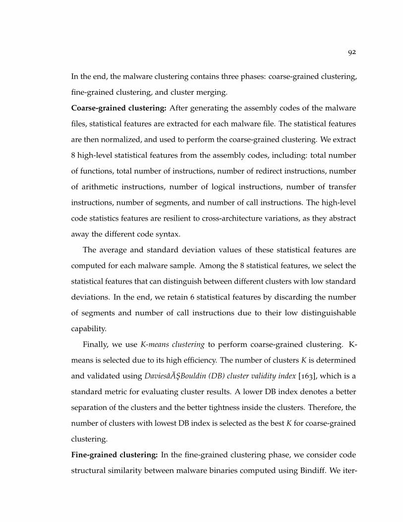
92
In the end, the malware clustering contains three phases: coarse-grained clustering,
fine-grained clustering, and cluster merging.
Coarse-grained clustering: After generating the assembly codes of the malware
files, statistical features are extracted for each malware file. The statistical features
are then normalized, and used to perform the coarse-grained clustering. We extract
8 high-level statistical features from the assembly codes, including: total number
of functions, total number of instructions, number of redirect instructions, number
of arithmetic instructions, number of logical instructions, number of transfer
instructions, number of segments, and number of call instructions. The high-level
code statistics features are resilient to cross-architecture variations, as they abstract
away the different code syntax.
The average and standard deviation values of these statistical features are
computed for each malware sample. Among the 8 statistical features, we select the
statistical features that can distinguish between different clusters with low standard
deviations. In the end, we retain 6 statistical features by discarding the number
of segments and number of call instructions due to their low distinguishable
capability.
Finally, we use K-means clustering to perform coarse-grained clustering. K-
means is selected due to its high efficiency. The number of clusters K is determined
and validated using DaviesâASBouldin (DB) cluster validity index [163], which is a
standard metric for evaluating cluster results. A lower DB index denotes a better
separation of the clusters and the better tightness inside the clusters. Therefore, the
number of clusters with lowest DB index is selected as the best K for coarse-grained
clustering.
Fine-grained clustering: In the fine-grained clustering phase, we consider code
structural similarity between malware binaries computed using Bindiff. We iter-

93
atively compute the pairwise structural similarity between every malware pair
within a cluster derived from coarse-grained clustering. The intuition is that high-
level structural similarity generated by Bindiff is more resilient to cross-architecture
variations [106], and can attain high accuracy in matching functions. This process
yields an N × N similarity matrix (N is the number of malware samples), where
the values in each row represent the similarity scores computed by Bindiff for a
single malware sample against all other malware samples in the dataset.
Here, we utilize a popular binary similarity analysis tool, Bindiff [164], for
computing the similarity between the malware samples in our dataset. Bindiff is
a popular tool for computing structural similarity. It reconstructs Control Flow
Graph (CFG) of each binary file to perform function and basic block matching, and
then compares functions and basic blocks by extracting the graph-based features
such as number of incoming/outgoing edges, the position of basic blocks in the
CFG, etc. In order to tolerate the code differences brought by cross-architecture
compilations, Bindiff abstracts the structural features of a binary file, while ignoring
the specific assembly-level instructions. It retains a trade-off between similarity
analysis accuracy and efficiency by applying a multi-level matching strategy based
on function and basic block level structural attributes. The final result of Bindiff is
a list of matched and unmatched functions from both binaries, based on which the
similarity score (ranging in [0, 1]) is computed [164]. Bindiff is fairly efficient, and
the matches it produces are proven accurate [106]. Therefore, in this clustering
stage, we assign a relatively large cluster number to ensure every cluster is compact
enough to contain all the similar malware samples.
In the fine-grained clustering, we partition the malware samples within each
coarse-grained cluster into multiple fine-grained clusters using the single-linkage
hierarchical clustering. We choose hierarchical clustering, because of its ability

94
to find clusters of arbitrary shapes with arbitrary distance metrics. The hierar-
chical clustering takes a matrix of pairwise distances among malware samples
and generates a dendrogram, which is a tree-like data structure to represent the
clustering outcome. Dendrogram cutoff determines the number of clusters. Dis-
tance measurement is critical for performing hierarchical clustering, and we derive
the distance measurements through binary similarity analysis, which identifies
common characteristics of malware samples at different levels including basic
block, function, and file levels.
Rather than converting the similarity score to distance measurement which may
lose accuracies, we propose to utilize similarity scores as features. The rationale lies
on the fact that similar malware samples will have comparative similarity scores
with other samples. Therefore, among N malware samples, each sample will have
N similarity scores as a feature vector, which contains the malware’s similarity
score with itself (i.e., 100%) and with all other malware samples in the dataset.
In order to minimize the impact of this high and ineffective self-similarity score,
for malware A, we replace this self-similarity score with the highest similarity
score of malware A compared with all other samples. Using similarity scores
as features, we compute the distance measurements using Euclidean distance.
The hierarchical clustering is conducted using the calculated distances among all
samples. Similar to the coarse-grained clustering, the best number of fine-grained
cluster is determined using DB cluster validity index for every coarse-grained
cluster.

95
5.2.3 Cluster Merging
After splitting the coarse-grained clusters into the fine-grained clusters, some of
the generated clusters may actually share a high similarity, which can then be
merged together. Consequently, we use string features to merge clusters and refine
clustering results. The cluster refinement involves two steps: 1) string feature
analysis: N-gram text analysis is used to extract distinguishable string features
from the printable strings; and 2) merging clusters: clusters are merged based on
the similarity analysis of string features.
String feature analysis: The goal of string feature analysis is to find the string
features that represent all malware samples of each cluster, since string features
exhibit rich contextual information that is suitable for fine-grained analysis. String feature
analysis facilitates the detection of cross-architecture IoT malware, as printable
strings likely remain the same for binaries even when they are compiled differently.
To this end, printable strings are extracted from each malware sample, which are
used as inputs to generate N-gram string vectors, capturing the sequential order
of strings. Punctuation marks, such as “:", “//", “;", are used to segment the
strings. For example, a string vector “wget http://198.12.97.79/bins.sh; chmod
777 bins.sh; sh bins.sh" is segmented into “wget http 198.12.97.79 bins.sh chmod
777 bins.sh sh bin.sh". In order to avoid the overfitting issue, we replace the ip
address with a special word “reIPaddress". Using N-gram, we are able to extract
meaningful word sequences, e.g., “wget http reIPaddress bins.sh", “chmod 777
bin.sh sh" (with 4-gram). For improving the effectiveness of N-gram string feature,
we remove any printable strings that contain less than three characters. We select
N value according to experimental analysis performed to retain a balance between
signature matching accuracy and efficiency, as described in Section 5.3.2.
96
Fig. 5.3 illustrates the string feature analysis. For each malware sample, we
extract the N-gram string vectors, and remove the duplicate N-gram string vectors.
Then, we combine the generated N-grams of all malware samples within a single
cluster. Frequency analysis is carried out to identify the most common N-gram
string vectors in each cluster. Consequently, we generate string features for each
cluster, consisting of the top K N-gram strings with the highest appearances
among all the N-gram strings in the combined string vector. The selection of K is
explained in Section 5.3.2, which aims at identifying the distinguishable N-gram
strings while minimizing computational costs. Thus, the top K N-gram strings are
used as features of each cluster to perform cluster merging.
N-gram from S1
.
.
.
.
.
.
.N-gram from Sn
Frequency Analysis
Generate top K N-gram
Figure 5.3: String feature analysis (S1,· · · , Sn are n samples in a cluster)
Merging clusters: Cluster merging is performed iteratively to refine the cluster-
ing results, which guarantees the malware clusters are both compact and well-
separated from each other. Algorithm 6 illustrates the cluster merging procedure.
After generating the top K N-gram strings for each cluster, we use Jaccard similar-
ity to compute the inter-cluster similarity scores between different clusters based on
the generated top K N-gram strings for each cluster. Clusters with a high string
similarity score (i.e., higher than a predefined merging threshold) will be merged.
After merging clusters, we evaluate the merged clusters again by recomputing
their top K N-gram string features, and the corresponding inter-cluster similarity
97
Algorithm 6 Cluster MergingRequired : τ = merging threshold, |C| is the current number of clusters, JS repre-
sents Jaccard Similarity. ci, cj are two clusters under evaluation, andSF(ci), SF(cj) are their top K N-gram string features, respectively.
for (each pair of ci, cj) doif (JS(SF(ci), SF(cj)) ≥ τ) then
Merge clusters ci, cj |C| = |C| − 1 Generate new string feature for everycluster
endend
scores. The cluster merging process can be iterated multiple times in sequence
until different clusters bearing low similarities (i.e., lower than the merging thresh-
old), which indicates a set of well-separated and distinguishable clusters. After
performing cluster merging, we can perform lightweight signature generation for
each cluster.
5.2.4 Signature Generation and Online Detection/Classification
The complete signature of each merged cluster contains the top-K N-gram string
feature (SF) extracted using the aforementioned method, and statistical feature
(ST) that represents the average values of each statistical feature. Both SF and ST
can be easily extracted from malware files, making the signature generation fairly
efficient.
The online detection/classification of IoT malware is a signature matching
process, where the matching is performed by computing the similarity between
the extracted signature from the suspicious file and a set of cluster signatures.
Euclidean distance d(STi, STj) is used for measuring similarity of the ST. To facilitate
similarity analysis, we convert the Euclidean distances into similarity scores [165],

98
named as Statistical Similarity (SS) and formalized as follows:
SS(STi, STj) =1
1 + d(STi, STj). (5.1)
On the other hand, Jaccard Similarity (JS) is used for computing similarity of the
SF, denoted as JS(SFi, SFj). The Overall Similarity (OS) score for the signature
matching will be a weighted sum of JS and SS, written as follows:
OS(i, j) = w1 · JS(SFi, SFj) + w2 · SS(STi, STj), (5.2)
where w1 + w2 = 1, and OS(i, j) represents the signature matching score between
file i and cluster j. In this research, we give a equal weight (i.e., 0.5) to SF and ST
by default, but the weight can be tuned according to analysis results, e.g., if string
obfuscation is identified, a higher weight can be assigned to ST. After computing
the OS scores between a file and all cluster signatures, we identify the highest
OS score as the file’s suspicion level. Meanwhile, the file can be classified into
the corresponding malware cluster or marked as benign. In our experiment in
Section 5.3, we show that the file’s suspicion level can be either a high value or
a low value, which makes it straightforward to classify a suspicious file as IoT
malware or benign samples.
The YARA tool [166] can be used for generating static signatures based on
a sequence of specific printable strings or bytes belonging to a malware family.
YARA signature for Mirai malware is shown in Listing 5.1, which includes the
printable string signature. While most YARA signatures are manually identified,
the proposed system can facilitate the automated identification of string signatures

99
for YARA. Therefore, we can easily incorporate YARA signatures in our system
for malware detection.
1 rule Mirai_1
2 {
3 meta:
4 description = "Mirai Variant 1"
5 author = "Mohannad / @moh"
6 date = "2017-04-16"
7 strings:
8 $dir1 = "/dev/watchdog"
9 $dir2 = "/dev/misc/watchdog"
10 condition:
11 $dir1 and $dir2
12 }
Listing 5.1: YARA Signature for Mirai
5.3 Evaluation
In this section, we evaluate the performance of our solution using the IoT malware
dataset. We first discuss our methodology for selecting the values of K and N,
and then evaluate the multi-stage clustering with cluster refinement method. The
malware detection performance is evaluated in terms of malware detection rate
and false positive rate. We further evaluate our system’s performance in classifying
the testing dataset, and benign linux firmware gleaned from various commercial
product websites.
100
5.3.1 Selecting Parameters K and N
Similar to other empirical approaches for selecting N-gram parameter [107, 167],
we also adopt an experimental approach driven by the data to select the best set
of parameters. In our approach, we use a set of values {90, 100, 150, 200, 250} for
selecting K, and a set of values {3, 4, 5, 6, 7} for selecting N, which are the key
parameters for defining top K N-gram string feature. Our intuition is that the
best K and N pair should produce the best clustering results, i.e., the samples in a
cluster should bear high similarity with each other, and different clusters should be
well separated. Thus, different combinations of K and N are considered with the
goal of maximizing the similarity within the same cluster (Intra-cluster similarity),
and minimizing the similarity among clusters (Inter-cluster similarity). Specifically,
the inter-cluster string similarity is defined as the average Jaccard similarity of
string features among different clusters. For intra-cluster string similarity, we
collect the top-K N-gram string features of all malware samples inside each cluster,
and compute the average Jaccard similarity of cluster string features with its
enclosed samples.
Determining best K: We examine the inter-cluster and intra-cluster string similarity
with different K values and fixed N value in order to determine the best K. Fig. 5.4
shows the string similarity results with different K values (when N is fixed as 4),
from which we can see there is a slight increase of both inter-cluster and intra-
cluster string similarity with the increase of K. To strike a balance between the
intra-cluster similarity (the higher the better) and the inter-cluster similarity (the
lower the better), we measure the difference between inter and intra-cluster string
similarity, i.e., the gap between two lines, and select the K with the maximal gap.
In the end, we select the best K = 100. For validation, we evaluate the performance
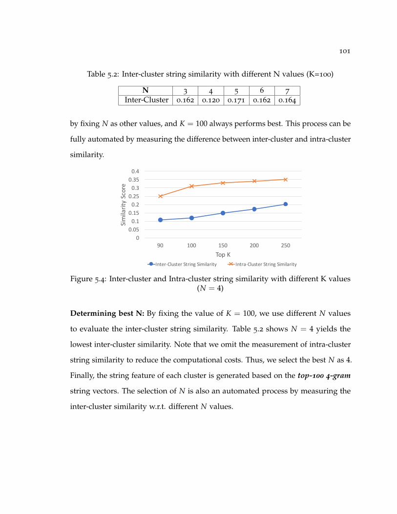
101
Table 5.2: Inter-cluster string similarity with different N values (K=100)
N 3 4 5 6 7
Inter-Cluster 0.162 0.120 0.171 0.162 0.164
by fixing N as other values, and K = 100 always performs best. This process can be
fully automated by measuring the difference between inter-cluster and intra-cluster
similarity.
00.050.10.150.20.250.30.350.4
90 100 150 200 250
SimilarityScore
TopKInter-ClusterStringSimilarity Intra-ClusterStringSimilarity
Figure 5.4: Inter-cluster and Intra-cluster string similarity with different K values(N = 4)
Determining best N: By fixing the value of K = 100, we use different N values
to evaluate the inter-cluster string similarity. Table 5.2 shows N = 4 yields the
lowest inter-cluster similarity. Note that we omit the measurement of intra-cluster
string similarity to reduce the computational costs. Thus, we select the best N as 4.
Finally, the string feature of each cluster is generated based on the top-100 4-gram
string vectors. The selection of N is also an automated process by measuring the
inter-cluster similarity w.r.t. different N values.
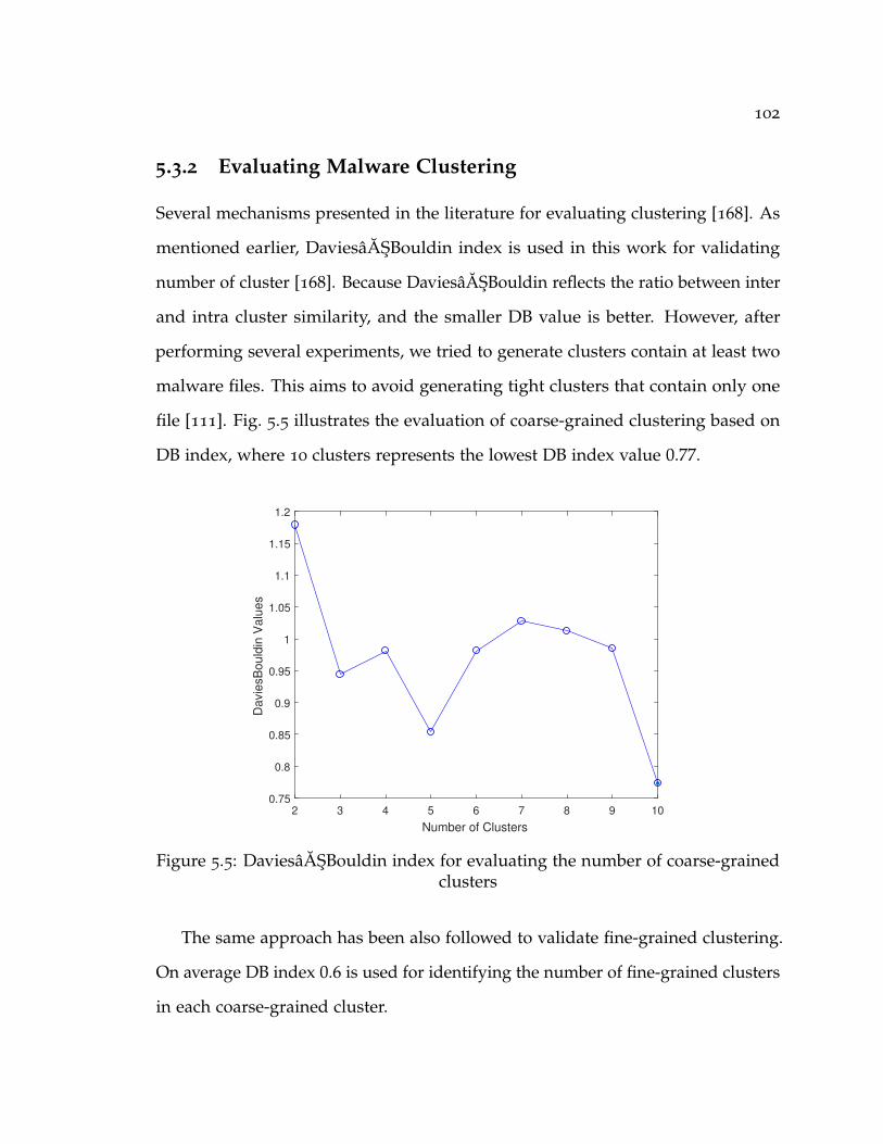
102
5.3.2 Evaluating Malware Clustering
Several mechanisms presented in the literature for evaluating clustering [168]. As
mentioned earlier, DaviesâASBouldin index is used in this work for validating
number of cluster [168]. Because DaviesâASBouldin reflects the ratio between inter
and intra cluster similarity, and the smaller DB value is better. However, after
performing several experiments, we tried to generate clusters contain at least two
malware files. This aims to avoid generating tight clusters that contain only one
file [111]. Fig. 5.5 illustrates the evaluation of coarse-grained clustering based on
DB index, where 10 clusters represents the lowest DB index value 0.77.
2 3 4 5 6 7 8 9 10
Number of Clusters
0.75
0.8
0.85
0.9
0.95
1
1.05
1.1
1.15
1.2
Da
vie
sB
ou
ldin
Va
lue
s
Figure 5.5: DaviesâASBouldin index for evaluating the number of coarse-grainedclusters
The same approach has been also followed to validate fine-grained clustering.
On average DB index 0.6 is used for identifying the number of fine-grained clusters
in each coarse-grained cluster.

103
Evaluating cluster merging using string feature: For merging clusters, we com-
pute the similarity scores using cluster string features. Recall that the cluster string
feature represents the top-100 4-gram string vectors of a cluster. Two clusters
will be merged, if the Jaccard similarity score of their cluster string features is
higher than a merging threshold. The merging threshold should be set sufficiently
high to avoid merging dissimilar clusters, but should not be set too high that may
prevent appropriate cluster merging. In this work, we empirically set the merging
threshold as 0.7 [111] to merge clusters that resemble each other. In the end, 153
original clusters are merged into 110 clusters, which are re-evaluated to make sure
they cannot be further merged.
Table 5.3: Summary of Clustering Results. The number of samples that have beenused for performing the clustering is 2000 files (training dataset). Therefore, allclustering and processing time measurements are based on the training dataset
Entire Dataset Clustering(Training Dataset)
Processing Time(sec)
# ofsam-ples
undetectedby all AVscanners
undetectedby best AVscanner
Coarse Fine AfterMerge
Coarse Fine AfterMerge
4078 2 (%0.49) 45 (%1.1) 10 153 110 0.01 2.48 2.85
Clustering Coherence: The compact of our clustering approach has been also
evaluated based on Virus Total detection results. We selected top-3 scanners
that have high detection rate. Namely, AVG, DrWeb and McAfee. Then, we
followed similar approach to [111] for generating malware families based on the
generated labels by each Virus Total scanner. The malware families are generated
by removing the last section of the generated label string, which is separated
by dot(.). For example, Linux.BackDoor.Fgt is the malware family that will be
generated for the following labels generated by DrWeb (Linux.BackDoor.Fgt.373,
Linux.BackDoor.Fgt.578, Linux.BackDoor.Fgt.11, Linux.BackDoor.Fgt.229).

104
Then we check the consistency of each cluster, generated after merging clusters,
by computing the distribution of malware family in each cluster, where it is
expected to have a dominant malware family. The results show cohesion clusters,
as the average malware family distribution is %92 for all clusters among the top-3
Virus Total scanners, as presented in Fig. 5.6, which shows the cohesion of the
generated clusters after performing the merge.
0
0.1
0.2
0.3
0.4
0.5
0.6
0.7
0.8
0.9
1
0% 10% 20% 30% 40% 50% 60% 70% 80% 90% 100%
Clu
ste
rs
Average Cohesion of Top-3 VT Scanners
Figure 5.6: Distribution of cluster cohesion
5.3.3 Evaluating Signature Detection
The cluster signature will include the string feature and statistical feature, gen-
erated using our IoT malware dataset. In this section, we evaluate the detection
accuracy and effectiveness of our cluster signature. A malware sample is detected
if its maximum OS value (i.e., overall similarity in Eq. 5.2) is higher than a detection
threshold. The detection threshold is set as a high value (i.e., 0.7) to reduce false
positive rate.

105
For conducting the evaluation of clusters’ signatures, we download a set of
benign firmware binaries from openwrt, while the second part of the IoT malware
dataset (testing dataset) is used for evaluating our approach. All the tested files
are in Linux ELF format. The benign firmware dataset contains 130 samples, while
the testing dataset contains 2078 malware samples. We generate the string and
statistical features for these benign and malware samples. Table 5.4 reports the
evaluation results, it shows the average statistical similarity of the testing dataset
94%, which is much higher than the average statistical similarity of the benign
ELFs. Also, the detection rate based on string signature is 0% for the benign ELFs,
while our solution can successfully detected malcious ELFs with 85.2% detection
rate.
Table 5.4: Statistical similarity of new benign/malicious samples with clusters’statistical signature and detection rate based on string signatures
Source # of Samples Average statisti-cal similarity
String SignatureDetection Rate
Benign Firmware 130 41% 0%Testing Dataset 2078 94% 85.2%
Performance comparison: We also conduct performance comparisons with two
existing works based on API call sequences [103] and operation code (OpCode)
N-grams [107]. The results are shown in Table 5.5, and our detection method can
achieve significant performance improvement by capturing the unique characteris-
tics of IoT malware.
Table 5.5: Performance comparison
Comparison Detection Rate False Positive RateAPI Calls 64.8% 5.1%OpCode N-gram 66.0% 10.0%Our solution 85.2% 0%
106
5.3.4 Evaluating Runtime Performance
Table 5.3 presents the processing time required for processing and generating
the clusters. Clearly, our approach does not pose overhead, this is the result
of performing the clustering on multi-stages. The merging process took longer
time in comparison with coarse-grained and fine-grained clustering. This is
expected, because the merging process performs the iteration several times until
no similarity score exists above the threshold, and in every iteration N-gram string
analysis is performed again. We also evaluate the runtime performance of our
signature matching mechanism on an ARM platform using QEMU [169]. We run
experiments inside an emulator with ARM Cortex-A9 CPU (0.8GHz to 2GHz) and
256MB of RAM. The running time is 15ms for matching/classifying a new binary
file. Although many IoT devices have lower configurations than our emulator, we
believe the running time performance indicates the efficiency of our mechanism.
In future, we will evaluate our mechanism on real IoT devices.
5.4 Discussion
Evasive techniques: The proposed approach for generating lightweight detection
signatures utilizes printable strings as string features. As a result, our approach
is susceptible to string obfuscation and encryption techniques. To date, the IoT
malware samples are still very premature compared with their sophisticated
PC counterpart, and we have not observed any IoT malware employing code
obfuscation/encryption techniques. We believe the proposed system addresses
a timely need to provide an effective first-line defense on IoT devices, and it
also contributes to a better understanding of IoT malware.On the other hand, we
envision that the sophistication level of IoT malware will definitely grow.

107
Unknown malware: Another caveat is that our system cannot deal with unknown IoT
malware, so that we need to constantly update the signatures as new IoT samples
are discovered. But the update can be conducted offline on a computationally rich
hub. For instance, we can generate updated signatures everyday to keep up the
rapid change of IoT malware. Moreover, as shown in [170], the structural features
suffer from the variations caused by different compilation options, which may
induce false classification results.
Threshold setting: There are multiple thresholds in our system, including: merg-
ing threshold (set as 0.7), sample matching threshold (set as 0.9), and detection
threshold (set as 0.7). Currently, we use empirical approaches to identify an ap-
propriate threshold by evaluating over two opposite training datasets, e.g., one
contains the malware belonging to a family called “insider", and one contains the
samples outside the family called “outsider". The minimum value of all insiders
and maximum value of all outsiders can be identified, and the threshold is set to
the mean of these two values that optimizes the separation of the two different
worlds. This process can be automated to relieve the manual burden. It is evident
that for different datasets, we may need to adjust these threshold accordingly.
5.5 Summary
This chapter investigated the emerging IoT malware detection problem, and
proposed an efficient signature generation and classification mechanism for cross-
architecture IoT malware. Based on static analysis, the proposed mechanism
utilizes string, statistical and structural features for classifying IoT malware, where
Bindiff is used for computing structural similarities, and N-gram printable string
vectors and statistical features are extracted for characterizing the malware families.

108
The experimental results show the effectiveness and efficiency of our signature
generation system.
109
6 Towards Best Secure Coding Practice for
Implementing SSL/TLS
Developers often make mistakes while incorporating SSL/TLS functionality in
their applications due to the complication in implementing SSL/TLS and their
fast prototyping requirement. Insecure implementations of SSL/TLS are subject
to different types of Man in The Middle (MiTM) attacks, which ultimately makes
the communication between the two parties vulnerable to eavesdropping and
hijacking attacks, thereby violating confidentiality and integrity of the exchanged
information. This chapter aims to support developers in detecting insecure SS-
L/TLS implementation in their codes by utilizing a low-cost cross-language static
analysis tool called PMD. In the end, two insecure implementations of SSL/TLS
have been identified, and subsequently a new PMD rule set is created. This rule set
consists of three rules for addressing hostname validation vulnerability and certificate
validation vulnerability. The rules have been evaluated over 1, 517 code snippets
obtained from Stack Overflow, and the results show that 71% of the code snippets
contain insecure SSL/TLS patterns. The detection rate of our approach is 100%,
while it detects 165 violations inside the vulnerable code snippets in total.

110
6.1 Background
This section describes background knowledge about static analysis tools for de-
tecting bugs, and introduces our criteria for selecting the tool to implement our
detection rules. Static analysis and dynamic analysis solutions have been intro-
duced for detecting vulnerability in the applications. Since this work aims at
assisting developers in detecting insecure implementation of SSL/TLS, we will
review and compare some state-of-the-art solutions proposed for detecting pro-
gramming bugs using static analysis techniques.
Several open source static analysis tools are presented for detecting bugs in
Java programs, including:
1. FindBugs [171]: is an open source tool for detecting bugs in Java code. It is a
static analysis tool on Java bytecode, and can be used via command line and
integrated into different IDEs. FindBugs can discover various types of bugs
including problematic coding practice and vulnerabilities. FindBugs rules
can be created using Visitor pattern (Java API). However, this tool does not
detect insecure SSL/TLS implementation patterns.
2. Hammurapi [172]: is an open source tool for analyzing Java source code.
It can be integrated to IDEs, and is developed with scalability in mind.
Hammurapi employs Abstract Syntax Tree (AST), where new rules can be
added to this tool, using java code or XML rules. However, this tool is rather
complicated [173], and does not focus on detecting security vulnerabilities
and insecure implementation patterns.
3. Jlint [174]: is written in C++ for detecting common programming errors in
Java (e.g., race condition). Jlint performs semantic and syntax analysis on

111
Java bytecode for accomplishing its duties. Therefore, Jlint is not intended for
the check and validation of insecure SSL/TLS implementation, nor any kind
of other security checks. Although new rules can be integrated into Jlint, it
will require modifying Jlint’s source code [173], which makes Jlint difficult to
expand.
4. PMD: is an open source tool, which is written in Java and it checks Java
source code for a set of predefined bugs. PMD can be used through com-
mand line, and graphical user interface via the available plugins for various
IDEs. PMD constructs Abstract Syntax Tree (AST), and then examines the
constructed AST for detecting bugs. PMD checks for some security bugs, but
it neither checks insecure cryptographic mechanisms, nor examines SSL/TLS
implementations. PMD rules can be defined using Java code (Visitor pattern)
or XPath queries. This provides more flexibility and makes it easier for
extension.
We define two selection criteria for identifying the optimal tool to develop our
detection rules. The tool should be:
1. open source and is still actively supported by the community.
2. easy-to-use and facilitating the integration of new rules.
Accordingly, PMD has been selected for implementing our new rules to detect
insecure SSL/TLS implementations, because PMD is an open source tool, and can
be easily expanded with new rule sets. Unlike other tools that require changing
the source codes of the tools, or are limited to a specific method for adding new
rules, PMD is flexible, easy-to use, and deemed as a cross-architectural analysis
tool, as it can analyze different programming languages.
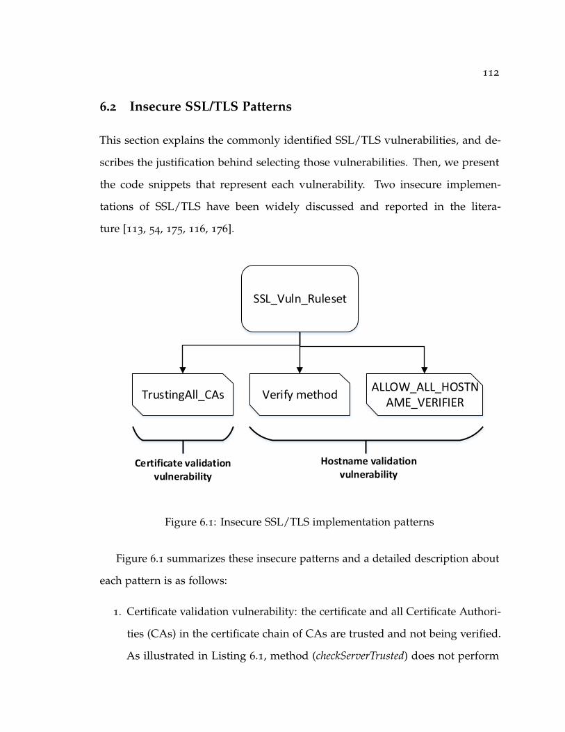
112
6.2 Insecure SSL/TLS Patterns
This section explains the commonly identified SSL/TLS vulnerabilities, and de-
scribes the justification behind selecting those vulnerabilities. Then, we present
the code snippets that represent each vulnerability. Two insecure implemen-
tations of SSL/TLS have been widely discussed and reported in the litera-
ture [113, 54, 175, 116, 176].
SSL_Vuln_Ruleset
TrustingAll_CAs Verify methodALLOW_ALL_HOSTN
AME_VERIFIER
Hostname validation vulnerability
Certificate validation vulnerability
Figure 6.1: Insecure SSL/TLS implementation patterns
Figure 6.1 summarizes these insecure patterns and a detailed description about
each pattern is as follows:
1. Certificate validation vulnerability: the certificate and all Certificate Authori-
ties (CAs) in the certificate chain of CAs are trusted and not being verified.
As illustrated in Listing 6.1, method (checkServerTrusted) does not perform
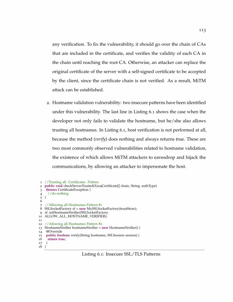
113
any verification. To fix the vulnerability, it should go over the chain of CAs
that are included in the certificate, and verifies the validity of each CA in
the chain until reaching the root CA. Otherwise, an attacker can replace the
original certificate of the server with a self-signed certificate to be accepted
by the client, since the certificate chain is not verified. As a result, MiTM
attack can be established.
2. Hostname validation vulnerability: two insecure patterns have been identified
under this vulnerability. The last line in Listing 6.1 shows the case when the
developer not only fails to validate the hostname, but he/she also allows
trusting all hostnames. In Listing 6.1, host verification is not performed at all,
because the method (verify) does nothing and always returns true. These are
two most commonly observed vulnerabilities related to hostname validation,
the existence of which allows MiTM attackers to eavesdrop and hijack the
communications, by allowing an attacker to impersonate the host.
1 //Trusting all Certificates Pattern2 public void checkServerTrusted(X509Certificate[] chain, String authType)3 throws CertificateException {4 //do nothing5 }6
7 //Allowing all Hostnames Pattern #1
8 SSLSocketFactory sf = new MySSLSocketFactory(trustStore);9 sf .setHostnameVerifier(SSLSocketFactory.
10 ALLOW_ALL_HOSTNAME_VERIFIER);11
12 //Allowing all Hostnames Pattern #2
13 HostnameVerifier hostnameVerifier = new HostnameVerifier() {14 @Override15 public boolean verify(String hostname, SSLSession session) {16 return true;17 }18 }
Listing 6.1: Insecure SSL/TLS Patterns

114
6.3 Proposed PMD Rulesets
The goal of this work is to create new rules for detecting insecure SSL/TLS
implementation patterns. In this section, we describe the architecture of PMD and
the supported methods for creating new PMD rules, introduce our assumption,
and demonstrate the proposed PMD rulesets for accurately detecting the insecure
SSL/TLS implementation patterns.
6.3.1 PMD Rulesets and Rules
Figure 6.2 illustrates the architecture of PMD, which includes the newly proposed
ruleset (described in Section 6.2). A Java class is analyzed by generating its
Abstract Syntax Tree. The analyzer then examines the generated AST against a set
of predefined rules, and finally a report will be generated that displays the detected
bugs. Even though Data Flow Analysis (DFA) has been integrated into PMD, PMD
has not supported creating rules based on DFA yet. PMD rules are organized
based on different categories (formally known as Rulesets), while each ruleset
contains several rules that address a single bug. Therefore, each rule possesses
several properties like a description of the bug, the priority, and the detection rule.
We extend the PMD rules by adding a novel ruleset, which consists of three
rules for detecting the selected insecure SSL/TLS patterns. Figure 6.3 depicts the
structure of PMD rules.
As mentioned earlier, one of the main advantages of using PMD is the support
for different methods to create new rules. In this work, two methods can be used
for creating new PMD rule set and rules:

115
PMD Rulesets
Java Class
PMD Engine
AST Generator Analyzer
SSL_Vuln_Ruleset
TrustingAll_CAs Verify MethodALLOW_ALL_HOSTNAME_VERIFIER
Hostname validation vulnerability
Certificate validation
vulnerability
SSL_Vuln_Ruleset
Figure 6.2: PMD architecture and the proposed PMD rulesets (SSL_Vuln_Ruleset)
PMD Ruleset
PMD Rule 1 PMD Rule 2 PMD Rule n…...
Figure 6.3: PMD ruleset structure
1- Java class: PMD rule can be written as a Java class that extends Abstract-
JavaRule, and Visitor API can then be used for inspecting some properties in the
generated AST of the class under analysis. Then, this rule class can be declared
under a specific PMD ruleset.

116
2- XPath quires: this method treats the generated AST as an XML file, then we
can write XPath queries to find specific patterns. PMD provides a handy tool for
designing XPath queries called PMD rule designer,which can be used for generating
the AST for the targeted pattern and creating the XPath query. Listing 6.2 presents
an XPath that have been created using PMD rule designer for the insecure pattern
presented in Listing 6.1.
1 //MethodDeclaration[@Name='checkServerTrusted'
2 and
3 Block[count(*) = 0]]
Listing 6.2: Allowing all Hostnames Pattern #2
In this work, XPath method is utilized for creating the rules, and PMD rule
designer has facilitated and simplified the rule creation process. The designer tool
contains four windows, namely the source code (top-left), XPath query (top-right),
AST & DFA (bottom-left), and the result of XPath query (bottom-right). Our main
assumption here is that the developers strive to detect any insecure implementations, and
develop more secure applications. This is a reasonable assumption as most developers
have already recognized the importance of the security of their applications.
Therefore, the developers apply PMD and the corresponding rulesets to detect the
security vulnerabilities in their applications.
Here are the detailed steps for the developers to construct the SSL_Vuln_Ruleset
to detect SSL/TLS implementation vulnerabilities:
1. Obtaining the source code of PMD, as we want to add new rules, it should
be rebuilt again using Maven after adding new rules.
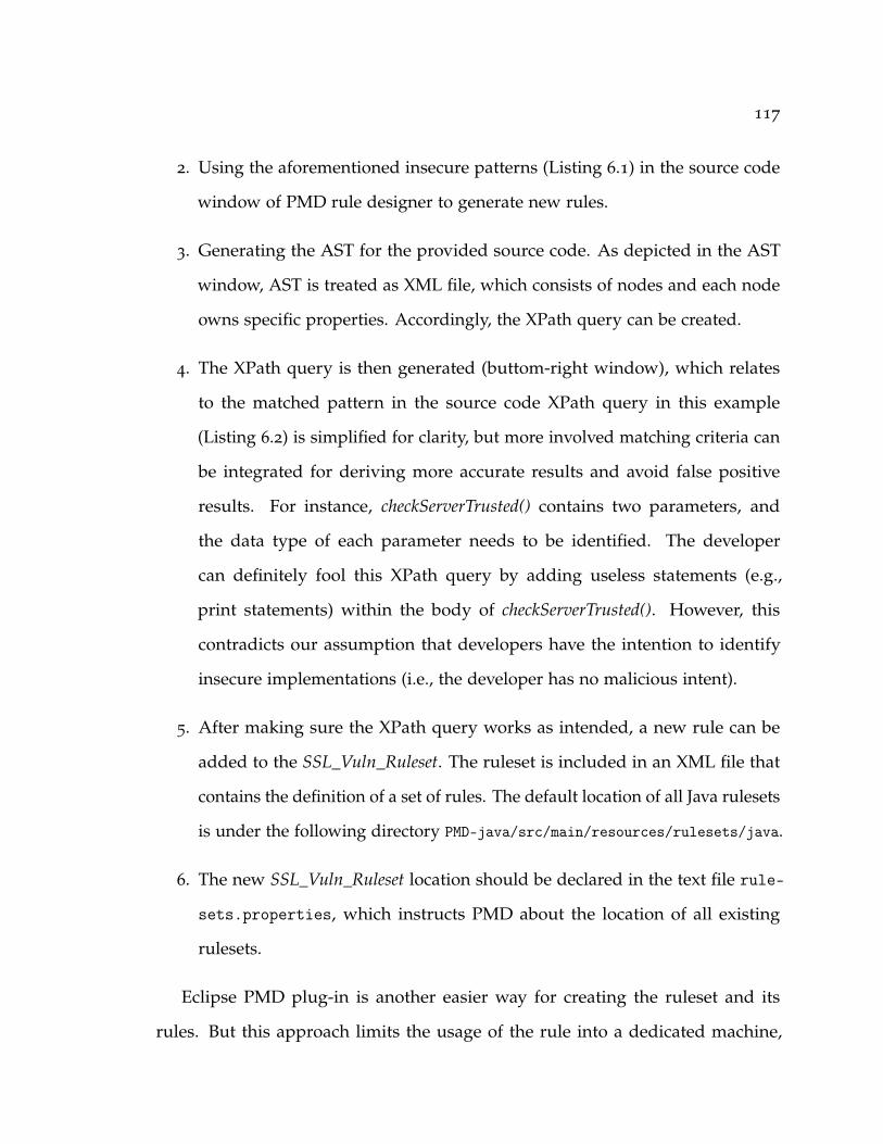
117
2. Using the aforementioned insecure patterns (Listing 6.1) in the source code
window of PMD rule designer to generate new rules.
3. Generating the AST for the provided source code. As depicted in the AST
window, AST is treated as XML file, which consists of nodes and each node
owns specific properties. Accordingly, the XPath query can be created.
4. The XPath query is then generated (buttom-right window), which relates
to the matched pattern in the source code XPath query in this example
(Listing 6.2) is simplified for clarity, but more involved matching criteria can
be integrated for deriving more accurate results and avoid false positive
results. For instance, checkServerTrusted() contains two parameters, and
the data type of each parameter needs to be identified. The developer
can definitely fool this XPath query by adding useless statements (e.g.,
print statements) within the body of checkServerTrusted(). However, this
contradicts our assumption that developers have the intention to identify
insecure implementations (i.e., the developer has no malicious intent).
5. After making sure the XPath query works as intended, a new rule can be
added to the SSL_Vuln_Ruleset. The ruleset is included in an XML file that
contains the definition of a set of rules. The default location of all Java rulesets
is under the following directory PMD-java/src/main/resources/rulesets/java.
6. The new SSL_Vuln_Ruleset location should be declared in the text file rule-
sets.properties, which instructs PMD about the location of all existing
rulesets.
Eclipse PMD plug-in is another easier way for creating the ruleset and its
rules. But this approach limits the usage of the rule into a dedicated machine,
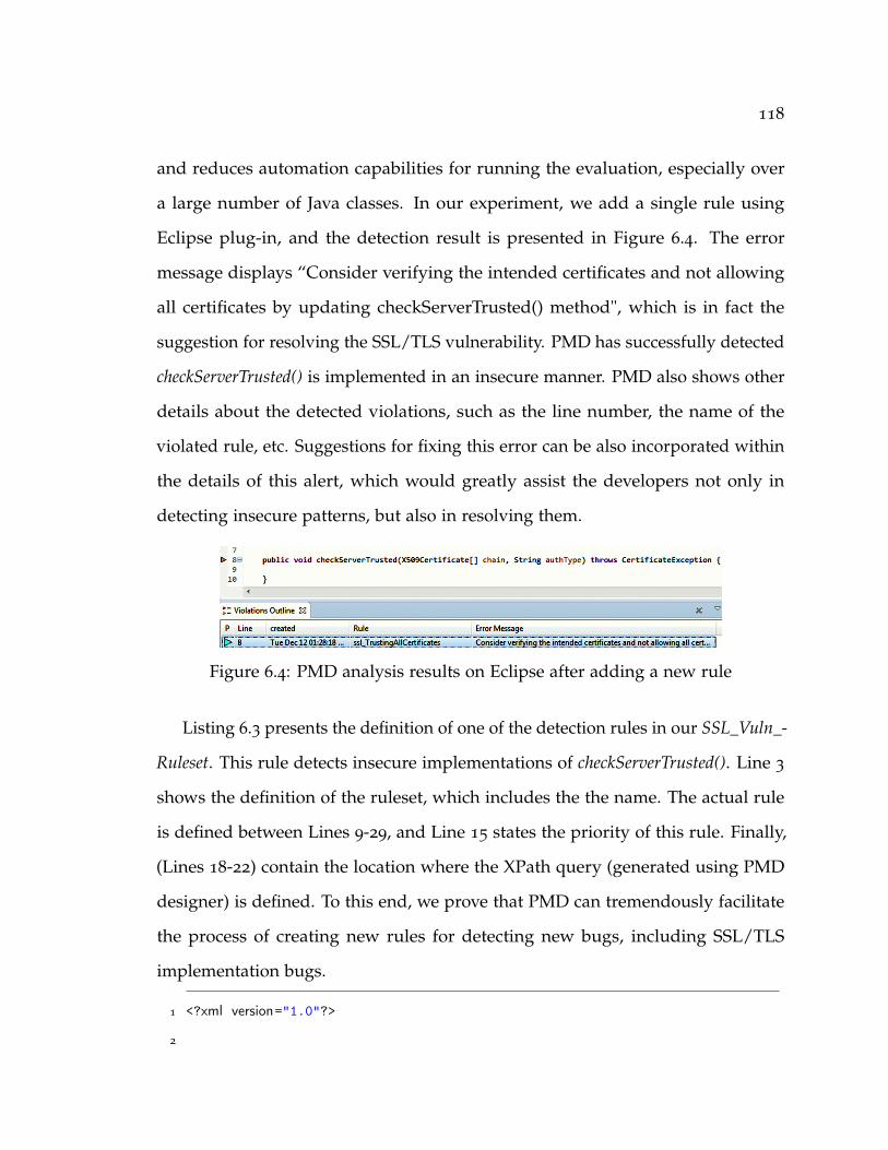
118
and reduces automation capabilities for running the evaluation, especially over
a large number of Java classes. In our experiment, we add a single rule using
Eclipse plug-in, and the detection result is presented in Figure 6.4. The error
message displays “Consider verifying the intended certificates and not allowing
all certificates by updating checkServerTrusted() method", which is in fact the
suggestion for resolving the SSL/TLS vulnerability. PMD has successfully detected
checkServerTrusted() is implemented in an insecure manner. PMD also shows other
details about the detected violations, such as the line number, the name of the
violated rule, etc. Suggestions for fixing this error can be also incorporated within
the details of this alert, which would greatly assist the developers not only in
detecting insecure patterns, but also in resolving them.
Figure 6.4: PMD analysis results on Eclipse after adding a new rule
Listing 6.3 presents the definition of one of the detection rules in our SSL_Vuln_-
Ruleset. This rule detects insecure implementations of checkServerTrusted(). Line 3
shows the definition of the ruleset, which includes the the name. The actual rule
is defined between Lines 9-29, and Line 15 states the priority of this rule. Finally,
(Lines 18-22) contain the location where the XPath query (generated using PMD
designer) is defined. To this end, we prove that PMD can tremendously facilitate
the process of creating new rules for detecting new bugs, including SSL/TLS
implementation bugs.
1 <?xml version="1.0"?>
2

119
3 <ruleset name="SSL_Vuln_Ruleset">
4
5 <description>
6 This ruleset detects insecure implementation of SSL/TLS
7 </description>
8
9 <rule name="TrustingAllCAs"
10 language="java"
11 message="Consider verifying the intended certificates and not allowing all
↪→ certificates"
12 <description>
13 This is an insecure implementation of SSL/TLS, which trusts ALL
↪→ certificates.
14 </description>
15 <priority>3</priority>
16 <properties>
17 <property name="xpath">
18 <value>
19 <![CDATA[
20 //MethodDeclaration[@Name='checkServerTrusted'
21 and Block[count(*) = 0]] ]]>
22 </value>
23 </property>
24 </properties>
25 <example>
26 <![CDATA[
27 ]]>
28 </example>
29 </rule>
30 </ruleset>

120
Listing 6.3: Definition of SSL_Vuln_Ruleset
6.4 Evaluation
This section describes our evaluation approach, including two research questions,
and the results we get to answer each research question.
We conducted the evaluation over a dataset obtained from [54]. This dataset
consists of 1,517 code snippets extracted from Stack Overflow website. However,
these codes cover all cryptographic implementations and are not only limited to
SSL/TLS implementations. Hence, we conducted data filtration over two phases.
In the first phase, codes that contain these keywords (SSL, TLS, ssl, tls, X509
and x509) are shortlisted. In the end, 597 code snippets have be shortlisted after
this phase. This phase provides us all code snippets that contain SSL and TLS
implementation. In the second phase, 263 files are obtained, which contain the
following keywords (verify, checkServerTrusted, ALLOW_ALL_HOSTNAME_-
VERIFIER). The purpose of this filtration phase is shortlisting the code snippets
that are related to the insecure patterns. We focus on answering the following two
research questions:
• RQ1: How well do our detection rules perform in practice, and can they
effectively detect the identified insecure patterns in real-world applications?
• RQ2: What is the runtime performance of PMD after using our rules?
All experiments have been performed on Ubuntu 16.04 virtual machine and
4GB memory. The modifications have been performed on the source code of PMD
version 5.8.1.
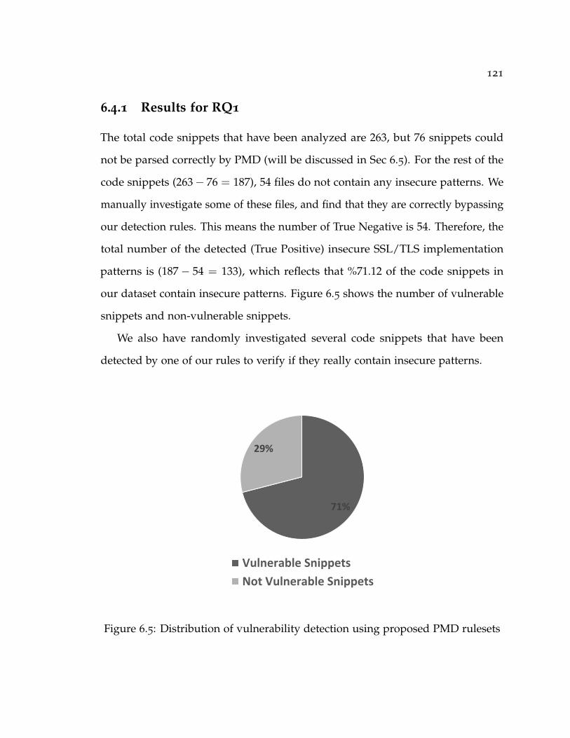
121
6.4.1 Results for RQ1
The total code snippets that have been analyzed are 263, but 76 snippets could
not be parsed correctly by PMD (will be discussed in Sec 6.5). For the rest of the
code snippets (263− 76 = 187), 54 files do not contain any insecure patterns. We
manually investigate some of these files, and find that they are correctly bypassing
our detection rules. This means the number of True Negative is 54. Therefore, the
total number of the detected (True Positive) insecure SSL/TLS implementation
patterns is (187− 54 = 133), which reflects that %71.12 of the code snippets in
our dataset contain insecure patterns. Figure 6.5 shows the number of vulnerable
snippets and non-vulnerable snippets.
We also have randomly investigated several code snippets that have been
detected by one of our rules to verify if they really contain insecure patterns.
71%
29%
Vulnerable Snippets
Not Vulnerable Snippets
Figure 6.5: Distribution of vulnerability detection using proposed PMD rulesets

122
Table 6.1 lists the detection results of the proposed SSL_Vuln_Ruleset in Fig-
ure 6.1. The most common insecure patterns are “Trusting All CAs" and “Allowing
All Hostname Verifier". We discover that several code snippets even contain more
than one insecure patterns.
Table 6.1: Detection results
Matching Insecure Patterns Matched Code SnippetsTrustingAll_CAs 43
Verify Method 18
ALLOW_ALL_HOSTNAME_VERIFIER 40
TrustingAll_CAs & Verify Method 24
TrustingAll_CAs & ALLOW_ALL_HOSTNAME_VERIFIER 8
Verify Method & ALLOW_ALL_HOSTNAME_VERIFIER 0
Figure 6.6 presents the detection results based on the identified two categories
of SSL/TLS vulnerabilities. The number of detection alarms does not match
the number of vulnerable code snippets, because as mentioned earlier a single
vulnerable code snippets can contain more than one insecure patterns.
75
90
65
70
75
80
85
90
95
Certificate Validation Hostname Validation
# D
ete
ctio
n A
larm
s
Figure 6.6: Detection results according to the types of SSL/TLS Vulnerabilities
The results show the proposed detection rules have correctly identified the
insecure code snippets, and no code snippets have been misclassified (no False

123
Positive or False Negative). Therefore, the both detection precision and recall of
our approach are 100%.
6.4.2 Results for RQ2
Measuring the overhead that might be introduced after using the new rules is
crucial. Therefore, we compute the required time for analyzing the code snippets,
which includes the required time for identifying which rule has been violated,
and the time for parsing the generated XML report for each code snippet. The
total analysis time is 144 seconds for the dataset generated after the two phases of
filtration (263 code snippets). On average, the required time for analyzing each
code snippet against our three rules and parsing its XML report is 0.55 second,
which shows the efficiency of the proposed method.
6.5 Discussions
In this section, we provide a discussion on three limitation of our approach for
detecting the insecure patterns. First, after the filtration, we have 187 code snippets,
while some of the snippets cannot be analyzed. Although the current dataset
is sufficient for validating our new rules, in future, we need a larger dataset for
drawing more affirmed conclusions. Also, we observe the duplications in the code
snippets while performing the manual investigation. Furthermore, we performed
a quick validation over the code snippets that have not been parsed, and our
preliminary analysis shows that the AST of those file cannot be generated.
Second, even though the discussed tools in Section 6.1 does not consider the
particular problem that have been addressed in this work, we need to adapt

124
and then evaluate these other tools to compare their performance, efficiency and
usability against our proposed approach.
Finally, as discussed in Section 6.3, we assume the developers have the motiva-
tion to find any bugs in his/her code, which is a valid assumption. But there is a
possibility that the developers unintentionally inserts meaningless or debugging
statements, which invalidates our rules. However, this situation can be handled
by adding more conditions to the XPath query to avoid being inappropriately
bypassed. There are also some cases such as the one presented in Listing 6.4,
where a boolean variable holding a “true" value is returned rather than an explicit
“true" value. In this case, PMD Data Flow Analysis should be explored to handle
such cases.
boolean isTesting = true;
HostnameVerifier hostnameVerifier = new HostnameVerifier() {
@Override
public boolean verify(String hostname, SSLSession session) {
return isTesting;
}
}
Listing 6.4: Our rule fails to detect this insecure pattern that is similar to
Listing 6.1
6.6 Summary
This chapter sheds light on a vital implementation issue: insecure coding practices
while implementing SSL/TLS APIs in Java applications. Two common vulner-
abilities have been identified, while three insecure patterns that represent each
125
vulnerability have been defined. We employ PMD static analysis tool for imple-
menting our detection rules. After comparing it with other existing open source
tools, we adopt the XPath approach for creating the new rules. In our evaluation
with 187 code snippets from Stack Overflow website, we show that 71% of these
code snippets are vulnerable, as they are discovered to contain various insecure
patterns, which validates the effectiveness of our detection rules.
126
7 Conclusion and Future Research
This dissertation contributes to the body of knowledge by combining software
analysis techniques and vulnerability analysis mechanisms. In this dissertation, we
considered three key attributes of the emergent ecosystems that hinder traditional
security analysis. We then study the attributes in a certain software ecosystem, each
study aims to understand the security consequences and challenges, and finally
formalize our solution overcome the challenges. The three security challenges that
we considered are: detecting unsafe interactions between emergent apps, detecting
cross-architecture IoT malware, and propagation of insecure patterns resulted by
code reuse from StackOverflow. We proposed three security analysis frameworks
that can systemically and efficiently detect sophisticated unsafe interactions and
detect cross-architecture IoT malware. Lastly, we promote the best practices of
security APIs such as SSL/TLS. This chapter summarizes our contributions and
discusses potential future research directions:
7.1 Research Summary
The findings of the works conducted in this dissertation are summarized as follows:
• We develop Dina, the first inter-app vulnerability detection tool with the
capability of analyzing dynamically loaded code, to pinpoint the stealthy
inter-app communications that are concealed using reflection and DCL. Dina

127
combines static IAC analysis with incremental dynamic analysis to identify
potential IAC vulnerabilities within dynamically loaded code at runtime. We
analyze 3,000 popular benign apps and 14,000 malicious apps to identify their
reflection usage and IAC communications via reflection/DCL. Our results
confirm the prevalent usage of reflection and DCL in popular real-world
apps, wherein surreptitious IAC behaviors concealed by reflective calls have
been observed. We provide detailed case studies to assess how vulnerable
apps can be exploited to launch stealthy attacks through reflection and DCL.
Therefore, we believe further efforts are required to better regulate the usage
of reflection and DCL calls to close the attack avenues without undermining
their utilities.
• We proposed a novel approach and accompanying tool suite, called IotCom,
for compositional analysis of such hidden and unsafe interaction threats in a
given bundle of cyber and physical components co-located in an IoT environ-
ment. IotCom first utilizes a path-sensitive static analysis to automatically
generate an inter-procedural control flow graph (ICFG) for each app. It then
applies a novel graph abstraction technique to model the behavior relevant
to the devices connected to the app as a behavioral rule graph (BRG), which
derives rules from IoT apps via linking the triggers, actions, and logical con-
ditions of each control flow in each app then automatically generates formal
app specifications from the BRG models. Lastly, it uses a lightweight formal
analyzer [150] to check bundles of those models for violations of multiple
safety and security properties arising from interactions among the app’s
rules. The experimental results of evaluating IotCom against 36 prominent
IoT safety and security properties, in the context of hundreds of real-world

128
apps, corroborates its ability to effectively detect violations triggered through
both cyber and physical channels.
• We observe the cross-architectural similarity among malware samples from
the same family by investigating two real-world IoT malware datasets consist
of 5, 150 malware samples. Based on this keen observation, we propose a
multi-stage clustering mechanism to cluster these IoT malware samples into
multiple families. We then design an efficient signature generation scheme
to create signatures using reliable and easily extractable string and statistical
features. The string feature is extracted using N-gram text analysis, while the
statistical feature contains the code-level statistics. The experimental results
show the effectiveness and efficiency of our signature generation system.
• We shed the light on a vital implementation issue, insecure coding prac-
tices while implementing SSL/TLS APIs in Java and Android applications.
Two common vulnerabilities have been identified, while three insecure pat-
terns that represent each vulnerability have been defined. Therefore, we
contributed towards establishing secure coding practice for developers by
developing practical and ready to use rule sets (consisting of three rules)
using PMD to detect vulnerable SSL/TLS implementations. These rules can
accurately and efficiently identify potential SSL/TLS vulnerabilities, and help
raise developers’ awareness of insecure SSL/TLS implementation patterns.
7.2 Future Research Directions
The security analysis approaches contributed to this dissertation opens the horizon
for a range of new research opportunities. These research directions include: (1)
Performing cross-platform and cross-domain security analysis, in which unsafe

129
interactions can be resulted due to the interactions between IoT apps, IoT devices
and mobile apps; (2) Analyzing the propagation of vulnerabilities in the evolved
Android applications and identifying its correlation with the code quality; (3)
Investigating security weakness in emergent platforms like robotics platforms. In
the robotics area, Robotic Operating System (ROS) a prominent framework, which
lacks from the security absence; (4) Considering enforcement mechanisms to block
unsafe interactions and allow only safe behaviors. In the rest of this section, we
discuss in more detail some of these potential future work directions.
7.2.1 Cross-platforms interactions
Analyzing the interaction across various platforms, as in this dissertation, we
considered the interaction within the same platform. In Chapter 3, the considered
interactions are within the Android platform, while in Chapter 4, IotCom ana-
lyzes the interactions between IoT apps. However, we partially considered the
cross-platform interaction between IFTTT and Samsung SmartThings platforms in
IotCom. As a future research direction of this work, investigating the security con-
sequences of the whole chain of interactions between Android apps, IoT apps, and
IoT devices. Essentially, applications inter-dependency [177] reflects the presence
of shared resources and services that lead to hazards. For example, SmartThings
provides an Android app, known as a companion app, to install and manage
IoT apps. This companion app can be a valuable target because it constitutes a
centralized point that is trusted by IoT apps and devices [178, 72]. While in the
Robotics area, Android apps can be leveraged to create nodes and manage robots1.1http://wiki.ros.org/android

130
7.2.2 Smelling the Vulnerability in Open Source Android
Applications
In emergent software ecosystems, applications evolve to accommodate new ser-
vices and repair bugs [179]. These updates lead to code smells that can propagate
in the evolved versions of the application [180]. The goal of this work is to perform
correlation analysis to understand the relationship between the evolution of vulner-
abilities and the quality of the code. This understanding will ultimately support
developers in fixing their code and promoting secure code implementations. Con-
ducting the correlation analysis entails specifying a list of insecure patterns, which
can be accomplished in a similar way to our work [58] discussed in Chapter 6.
The vulnerable code patterns can be obtained from security communities such as
the Common Vulnerability Exposures (CVE), the National Vulnerability Database
(NVD), and the Common Weakness Enumeration (CWE).
7.2.2.1 Motivation
Code Smell in Android: the vast majority of existing work focus on detecting
code smells that affect code quality and violate best coding practices. Habchi et.
al, [181, 180] develop Sniffer for detecting only 8 code smells. Sniffer analyzes
the source code at each commit after processing open source projects. This
analysis aims to identify the lifespan of code smell in evolved projects. While
PAPRIKA [182] can analyze binary APKs without the need for the source code.
PAPRIKA considers only 17 code smells. aDOCTOR [183] another code smell
detection tool, and can identify 15 code smells. All prior tools do not consider the
detection of security code smells. Another research streamline aims to identify
vulnerabilities in open source software projects [184, 185]. Both tools perform their
131
empirical analysis by leveraging Snyk [186] to identify vulnerable dependencies
in various open-source projects. While the former performs the analysis on Java
projects, the latter analyzes JavaScript projects. However, none of these works
study the propagation of security vulnerabilities in the context of Android.
Detecting vulnerabilities in Android: The Android vulnerability has been widely
explored [56, 3, 187, 188, 189, 190], but the evolution of vulnerabilities in the
Android platform did not get sufficient attention and the existing work have
examined Android vulnerabilities in isolation of code smell. For example, Wu
et al., [191] does not investigate the evolution of vulnerabilities in Android apps,
instead, this work focuses on studying the propagation of vulnerabilities in the
Android framework based on published patching reports (known as Android
Security Bulletin[192]).
Correlation analysis in Android: In this domain of research, the security aspects
have not been studied on a large scale. Sultana et al., [193] perform a correla-
tion analysis between code smells and the existence of vulnerabilities. But the
experimental analysis is limited to few case studies, where vulnerable and non-
vulnerable versions of the same project are analyzed concerning the detected code
smells. Also, the evolution of these projects has not been considered. Another
study [194] explores the relation between software quality and security. This work
does not consider the evolution of the apps and does not assess the likelihood of
apps to be vulnerable. A limited investigation on the impact of three code smells
memory and CPU has been studied in [195]. While [196] investigates the relation
between code smells and architectural smells. This study studies the correlation
between 19 code smells and 4 architectural smells using 111 Java projects.
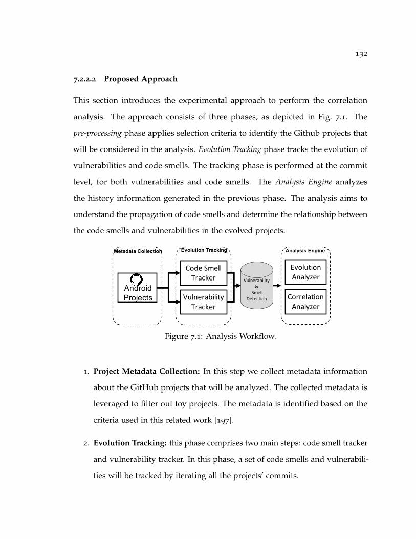
132
7.2.2.2 Proposed Approach
This section introduces the experimental approach to perform the correlation
analysis. The approach consists of three phases, as depicted in Fig. 7.1. The
pre-processing phase applies selection criteria to identify the Github projects that
will be considered in the analysis. Evolution Tracking phase tracks the evolution of
vulnerabilities and code smells. The tracking phase is performed at the commit
level, for both vulnerabilities and code smells. The Analysis Engine analyzes
the history information generated in the previous phase. The analysis aims to
understand the propagation of code smells and determine the relationship between
the code smells and vulnerabilities in the evolved projects.
Code Smell Tracker
VulnerabilityTracker
Correlation Analyzer
Metadata Collection Evolution Tracking Analysis Engine
Evolution AnalyzerVulnerability
&Smell
Detection
AndroidProjects
Figure 7.1: Analysis Workflow.
1. Project Metadata Collection: In this step we collect metadata information
about the GitHub projects that will be analyzed. The collected metadata is
leveraged to filter out toy projects. The metadata is identified based on the
criteria used in this related work [197].
2. Evolution Tracking: this phase comprises two main steps: code smell tracker
and vulnerability tracker. In this phase, a set of code smells and vulnerabili-
ties will be tracked by iterating all the projects’ commits.

133
3. Analysis Engine: this phase performs the analytical aspects, which involve
the evolution of analyzer and correlation analyzer. The evolution analyzer
identifies the introduction, survival, and removal of code smells and vulnera-
bilities. But the correlation analyzer determines the relation between code
smells and vulnerabilities.
7.2.3 Feature Interaction in Robotics Ecosystem
In Chapters 3 and 4, we address the challenge of detecting unsafe interactions
in the context of Android and Smart home. This challenge can be studied in the
robotics ecosystem. As robots comprise a set of sensing and actuation components
that interact with each other. The robot operating system (ROS) is one of the
prominent frameworks that are used in the robotics ecosystem. Therefore, the
usage of ROS is expected to be growing in industrial applications and academic
research. The security of ROS constitutes a major concern that can dismiss the
development of robotics systems.
The security aspect is not part of ROS’s goals, even security is overlooked
in the next version of ROS (ROS2), except a few security extensions that are
provided for optional use [198]. Therefore, ROS suffers from significant security
weaknesses including plaintext communications, open ports, and unencrypted
storage [199, 200, 201]. The state-of-the-art [202, 199, 203, 204, 205] show the
communication between ROS nodes is a major concern. Therefore, many of the
proposed solutions consider and demonstrated attacks target this limitation. Open
source penetration testing tools have been leveraged to perform the attacks on a
cyber-physical security honeypot developed on top of ROS [199]. The conducted
attacks show ROS suffers from major weaknesses, which allowed performing
134
man-in-the-middle attacks [206]. To overcome this challenge, a security layer is
proposed to be deployed on top of the ROS framework in [207]. This security layer
provides integrity and confidentiality by maintaining an authorization server to
enable secure communication between ROS nodes. Similarly, Breiling et al., [200]
proposes a secure communication channel for ROS to handle the communication
between two nodes.
Another experiment discovers over 100 publicly-accessible hosts running a ROS
master, after scanning the whole IPv4 scope [203]. The ability to perform this
experiment using a free network scanning tool represents a major risk, as ROS
master should not be made available on the public Internet. Where accessing the
master node allows the attacker to take control of the connected nodes. This work
takes a further step by attacking some of the discovered ROS nodes and shows how
this attack can have the potential to cause physical harm if used inappropriately.
However, none of these efforts have performed a systematic analysis to explore the
weaknesses of ROS, even none of these approaches have assessed the security of
ROS2. The future research directions in this area are:
• Conducting security analysis for understanding the safe and unsafe behaviors
of ROS nodes. A thorough static analysis can be performed similarly to [208].
• Analysing the usage of ROS APIs and identifying how these APIs can be
abused or misused. Dieber et al., [202] illustrates how some ROS APIs that
are used either for the communication between ROS nodes or ROS nodes
with the master node can be abused to add a fake ROS node.
135
7.2.4 Enforcement of Safe Interactions
In Chapters 3 and 4, we present mechanisms for detecting unsafe and undesired
interactions between apps. Both works can be extended by examining enforcement
mechanisms to strengthen detection solutions.
• Enforcement in the context of Android: Dina identifies vulnerable IAC.
This work can be extended by applying a real-time enforcement mechanism
similar to [29, 209]. Where the former requires performing formal verification
to synthesize the enforcement policies, while the latter applies the principle
of least-privilege.
• Enforcement in the context of Smart Home: IotCom can be strengthened
by blocking unsafe interactions in real-time. Several approaches have been
introduced in the smart home area. AutoTap [141] assists end-users in defin-
ing safety properties, it applies a formal method approach to synthesize the
safety properties. Therefore, AutoTap is not intended to perform real-time
enforcement. IoTGUARD [147] enforces a set of predefined policies based
on the run-time model that is generated based on the interaction between
apps at run time. However, IOTGUARD requires instrumenting the apps
before the installation. IoTGUARD does not generate the safety properties
automatically, it assumes the properties given by the user. This is not a prac-
tical approach because the pre-defined properties cannot accommodate all
potential interactions. Therefore the enforcement can be applied to IotCom
by combining the synthesis approach used in AutoTap and the runtime
model used in IOTGUARD.
136
Bibliography
[1] A. I. Wasserman, “Software engineering issues for mobile application de-
velopment,” in Proceedings of the FSE/SDP Workshop on Future of Software
Engineering Research, FoSER ’10, (New York, NY, USA), pp. 397–400, ACM,
2010.
[2] A. Taivalsaari and T. Mikkonen, “On the development of iot systems,” in
2018 Third International Conference on Fog and Mobile Edge Computing (FMEC),
pp. 13–19, April 2018.
[3] Y. Acar, M. Backes, S. Bugiel, S. Fahl, P. McDaniel, and M. Smith, “Sok:
Lessons learned from android security research for appified software plat-
forms,” in 2016 IEEE Symposium on Security and Privacy (SP), pp. 433–451,
May 2016.
[4] R. R. Filho, Emergent Software Systems. PhD thesis, School of Computing and
Communications, Lancaster University, 01 2018.
[5] D. Octeau, P. McDaniel, S. Jha, A. Bartel, E. Bodden, J. Klein, and Y. L. Traon,
“Effective Inter-Component Communication Mapping in Android with Epicc:
An Essential Step Towards Holistic Security Analysis,” in Proc. of USENIX
Security, 2013.

137
[6] Z. B. Celik, P. McDaniel, and G. Tan, “Soteria: Automated iot safety and
security analysis,” 2018.
[7] M. Abomhara and G. M. Kien, “Cyber Security and the Internet of Things:
Vulnerabilities, Threats, Intruders and Attacks,” Journal of Cyber Security and
Mobility, vol. 4, no. 1, pp. 65–88, 2015.
[8] S. Sicari, A. Rizzardi, L. A. Grieco, and A. Coen-Porisini, “Security, privacy
and trust in internet of things: The road ahead,” Computer Networks, vol. 76,
pp. 146–164, 2015.
[9] D. Navarro, F. Mieyeville, W. Du, M. Galos, and I. O’Connor, “Towards a
design framework for heterogeneous wireless sensor networks,” in 2011 1st
International Symposium on Access Spaces (ISAS), pp. 83–88, June 2011.
[10] S. Wang, A. Prakash, and T. Mitra, “Software support for heterogeneous com-
puting,” in 2018 IEEE Computer Society Annual Symposium on VLSI (ISVLSI),
pp. 756–762, July 2018.
[11] Y. J. Jia, Q. A. Chen, S. Wang, A. Rahmati, E. Fernandes, Z. M. Mao, and
A. Prakash, “ContexIoT: Towards Providing Contextual Integrity to Appified
IoT Platforms,” in Proceedings of the 21st Network and Distributed System
Security Symposium (NDSS’17), (San Diego, CA), February 2017.
[12] Y. Mehmood, F. Ahmad, I. Yaqoob, A. Adnane, M. Imran, and S. Guizani,
“Internet-of-things-based smart cities: Recent advances and challenges,” IEEE
Communications Magazine, vol. 55, pp. 16–24, Sep. 2017.

138
[13] W. Enck, M. Ongtang, and P. McDaniel, “On lightweight mobile phone ap-
plication certification,” in Proceedings of the 16th ACM Conference on Computer
and Communications Security, CCS ’09, pp. 235–245, 2009.
[14] M. Nakamura, H. Igaki, and K.-i. Matsumoto, “Feature interactions in in-
tegrated services of networked home appliances: An object-oriented ap-
proach.,” pp. 236–251, 01 2005.
[15] S. Apel, J. M. Atlee, L. Baresi, and P. Zave, “Feature interactions: the next
generation (dagstuhl seminar 14281),” in Dagstuhl Reports, vol. 4, Schloss
Dagstuhl-Leibniz-Zentrum fuer Informatik, 2014.
[16] S. Nguyen, “Feature-interaction aware configuration prioritization,” in Pro-
ceedings of the 2018 26th ACM Joint Meeting on European Software Engineer-
ing Conference and Symposium on the Foundations of Software Engineering, ES-
EC/FSE 2018, (New York, NY, USA), pp. 974–976, ACM, 2018.
[17] T. Pedersen, T. Le Guilly, A. P. Ravn, and A. Skou, “A method for model
checking feature interactions,” in 2015 10th International Joint Conference on
Software Technologies (ICSOFT), vol. 1, pp. 1–10, July 2015.
[18] S. Apel, S. Kolesnikov, N. Siegmund, C. Kästner, and B. Garvin, “Exploring
feature interactions in the wild: The new feature-interaction challenge,”
in Proceedings of the 5th International Workshop on Feature-Oriented Software
Development, FOSD ’13, (New York, NY, USA), pp. 1–8, ACM, 2013.
[19] P. Leelaprute, T. Matsuo, T. Tsuchiya, and T. Kikuno, “Detecting feature
interactions in home appliance networks,” in 2008 Ninth ACIS International
Conference on Software Engineering, Artificial Intelligence, Networking, and Paral-
lel/Distributed Computing, pp. 895–903, Aug 2008.

139
[20] W. Ahmad, C. Kästner, J. Sunshine, and J. Aldrich, “Inter-app communication
in android: Developer challenges,” in Proceedings of the 13th International
Conference on Mining Software Repositories, MSR ’16, (New York, NY, USA),
pp. 177–188, ACM, 2016.
[21] E. Chin, A. P. Felt, K. Greenwood, and D. Wagner, “Analyzing inter-
application communication in android,” in Proc. of MobiSys’11, pp. 239–252,
2011.
[22] L. R. Soares, J. Meinicke, S. Nadi, C. Kästner, and E. S. de Almeida, “Explor-
ing feature interactions without specifications: A controlled experiment,” in
Proceedings of the 17th ACM SIGPLAN International Conference on Generative
Programming: Concepts and Experiences, GPCE 2018, pp. 40–52, 2018.
[23] B. J. Muscedere, R. Hackman, D. Anbarnam, J. M. Atlee, I. J. Davis, and M. W.
Godfrey, “Detecting feature-interaction symptoms in automotive software
using lightweight analysis,” in 2019 IEEE 26th International Conference on
Software Analysis, Evolution and Reengineering (SANER), pp. 175–185, Feb
2019.
[24] W. Enck, M. Ongtang, and P. McDaniel, “Understanding android security,”
IEEE Security Privacy, vol. 7, pp. 50–57, Jan 2009.
[25] L. Li, T. F. Bissyandé, D. Octeau, and J. Klein, “DroidRA: Taming reflection
to support whole-program analysis of android apps,” in Proc. of ISSTA,
pp. 318–329, 2016.
[26] Y. Zhauniarovich, M. Ahmad, O. Gadyatskaya, B. Crispo, and F. Massacci,
“Stadyna: Addressing the problem of dynamic code updates in the security
analysis of android applications,” in Proc. of CODASPY ’15, pp. 37–48, 2015.
140
[27] D. Landman, A. Serebrenik, and J. J. Vinju, “Challenges for static analysis
of java reflection - literature review and empirical study,” in Proc. of ICSE,
pp. 507–518, May 2017.
[28] Y. Tsutano, S. Bachala, W. Srisa-an, G. Rothermel, and J. Dinh, “An efficient,
robust, and scalable approach for analyzing interacting android apps,” in
Proc. of ICSE, pp. 324–334, May 2017.
[29] H. Bagheri, A. Sadeghi, R. Jabbarvand, and S. Malek, “Practical, formal
synthesis and automatic enforcement of security policies for android,” in
Proc. of DSN, pp. 514–525, June 2016.
[30] M. Hammad, H. Bagheri, and S. Malek, “Determination and enforcement
of least-privilege architecture in android,” in Proc. of ICSA, pp. 59–68, April
2017.
[31] Y. K. Lee, J. y. Bang, G. Safi, A. Shahbazian, Y. Zhao, and N. Medvidovic, “A
sealant for inter-app security holes in android,” in Proc. of ICSE, pp. 312–323,
May 2017.
[32] E. Bodden, A. Sewe, J. Sinschek, H. Oueslati, and M. Mezini, “Taming
reflection: Aiding static analysis in the presence of reflection and custom
class loaders,” in Proc. of ICSE, pp. 241–250, 2011.
[33] Z. Qu, S. Alam, Y. Chen, X. Zhou, W. Hong, and R. Riley, “Dydroid: Measur-
ing dynamic code loading and its security implications in android applica-
tions,” in Proc. of DSN, pp. 415–426, June 2017.
[34] D. T. Nguyen, C. Song, Z. Qian, S. V. Krishnamurthy, E. J. M. Colbert, and
P. McDaniel, “Iotsan: Fortifying the safety of iot systems,” in Proceedings

141
of the 14th International Conference on Emerging Networking EXperiments and
Technologies, CoNEXT ’18, (New York, NY, USA), pp. 191–203, ACM, 2018.
[35] Z. B. Celik, P. McDaniel, and G. Tan, “Soteria: Automated iot safety and
security analysis,” in 2018 USENIX Annual Technical Conference (USENIX ATC
18), (Boston, MA), pp. 147–158, USENIX Association, 2018.
[36] W. Ding and H. Hu, “On the safety of iot device physical interaction con-
trol,” in Proceedings of the 2018 ACM SIGSAC Conference on Computer and
Communications Security, CCS ’18, (New York, NY, USA), pp. 832–846, ACM,
2018.
[37] “SmartThings Classic documentation.” https://docs.smartthings.com/en/
latest/ref-docs/reference.html, 2018.
[38] “Do more with smartthings - ifttt.” https://ifttt.com/smartthings, 2019.
[39] Y. Hu, Y. Zhang, J. Li, and D. Gu, “Cross-architecture binary semantics
understanding via similar code comparison,” in 2016 IEEE 23rd International
Conference on Software Analysis, Evolution, and Reengineering (SANER), vol. 1,
pp. 57–67, March 2016.
[40] M. Antonakakis, T. April, M. Bailey, M. Bernhard, E. Bursztein, J. Cochran,
Z. Durumeric, J. A. Halderman, L. Invernizzi, M. Kallitsis, D. Kumar,
C. Lever, Z. Ma, J. Mason, D. Menscher, C. Seaman, N. Sullivan, K. Thomas,
and Y. Zhou, “Understanding the mirai botnet,” in 26th USENIX Security
Symposium (USENIX Security 17), (Vancouver, BC), pp. 1093–1110, USENIX
Association, 2017.
142
[41] B. Herzberg, D. Bekerman, and I. Zeifman, “Breaking Down Mi-
rai: An IoT DDoS Botnet Analysis.” https://www.incapsula.com/blog/
malware-analysis-mirai-ddos-botnet.html, Accessed at Feb 21, 2017.
[42] “Amount of malware targeting smart devices more than doubled
in 2017.” https://www.kaspersky.com/about/press-releases/2017_
amount-of-malware-targeting-smart-devices-more-than-doubled-in-2017,
2017. Accessed at July 21, 2017.
[43] A. Taivalsaari and T. Mikkonen, “A roadmap to the programmable world:
Software challenges in the iot era,” IEEE Software, vol. 34, pp. 72–80, Jan
2017.
[44] T. Mikkonen and A. Taivalsaari, “Software reuse in the era of opportunistic
design,” IEEE Software, vol. 36, pp. 105–111, May 2019.
[45] S. K. Datta and C. Bonnet, “Easing iot application development through
datatweet framework,” in 2016 IEEE 3rd World Forum on Internet of Things
(WF-IoT), pp. 430–435, Dec 2016.
[46] P. Rosenkranz, M. Wählisch, E. Baccelli, and L. Ortmann, “A distributed
test system architecture for open-source iot software,” in Proceedings of the
2015 Workshop on IoT Challenges in Mobile and Industrial Systems, IoT-Sys ’15,
pp. 43–48, 2015.
[47] Matt Asay, “Open source near ubiquitous in IoT,
report finds.” https://readwrite.com/2016/05/04/
open-source-near-ubiquitous-iot-report-pl1/, Accessed at Oct 10,
2019.
143
[48] “About security alerts for vulnerable depen-
dencies.” https://help.github.com/en/articles/
about-security-alerts-for-vulnerable-dependencies, Sep. 2019.
[49] N. Neshenko, E. Bou-Harb, J. Crichigno, G. Kaddoum, and N. Ghani, “De-
mystifying iot security: An exhaustive survey on iot vulnerabilities and a
first empirical look on internet-scale iot exploitations,” IEEE Communications
Surveys Tutorials, vol. 21, pp. 2702–2733, thirdquarter 2019.
[50] S. Baltes, R. Kiefer, and S. Diehl, “Attribution required: Stack overflow code
snippets in github projects,” in 2017 IEEE/ACM 39th International Conference
on Software Engineering Companion (ICSE-C), pp. 161–163, May 2017.
[51] A. Lotter, S. A. Licorish, B. T. R. Savarimuthu, and S. Meldrum, “Code
reuse in stack overflow and popular open source java projects,” in 2018 25th
Australasian Software Engineering Conference (ASWEC), pp. 141–150, Nov 2018.
[52] W. Bai, O. Akgul, and M. L. Mazurek, “A qualitative investigation of in-
secure code propagation from online forums,” in 2019 IEEE Cybersecurity
Development (SecDev), IEEE.
[53] M. Verdi, A. Sami, J. Akhondali, F. Khomh, G. Uddin, and A. K. Motlagh,
“An empirical study of c++ vulnerabilities in crowd-sourced code examples,”
arXiv preprint arXiv:1910.01321, 2019.
[54] F. Fischer, K. BÃuttinger, H. Xiao, C. Stransky, Y. Acar, M. Backes, and S. Fahl,
“Stack overflow considered harmful? the impact of copy paste on android
application security,” in 2017 IEEE Symposium on Security and Privacy (SP),
pp. 121–136, May 2017.
144
[55] N. Meng, S. Nagy, D. Yao, W. Zhuang, and G. Arango-Argoty, “Secure
coding practices in java: Challenges and vulnerabilities,” in 2018 IEEE/ACM
40th International Conference on Software Engineering (ICSE), pp. 372–383, May
2018.
[56] M. Alhanahnah, Q. Yan, H. Bagheri, H. Zhou, Y. Tsutano, W. Srisa-an,
and X. Luo, “Detecting vulnerable android inter-app communication in
dynamically loaded code,” in IEEE INFOCOM 2019 - IEEE Conference on
Computer Communications, pp. 550–558, April 2019.
[57] M. Alhanahnah, Q. Lin, Q. Yan, N. Zhang, and Z. Chen, “Efficient signature
generation for classifying cross-architecture iot malware,” in 2018 IEEE
Conference on Communications and Network Security (CNS), pp. 1–9, May 2018.
[58] M. Alhanahnah and Q. Yan, “Towards best secure coding practice for im-
plementing ssl/tls,” in IEEE INFOCOM 2018 - IEEE Conference on Computer
Communications Workshops (INFOCOM WKSHPS), pp. 1–6, April 2018.
[59] A. Sadeghi, H. Bagheri, J. Garcia, and S. Malek, “A taxonomy and qualita-
tive comparison of program analysis techniques for security assessment of
android software,” IEEE Trans. Software Eng., vol. 43, no. 6, pp. 492–530, 2017.
[60] L. Li, A. Bartel, J. Klein, Y. L. Traon, S. Arzt, S. Rasthofer, E. Bodden,
D. Octeau, and P. McDaniel, “I know what leaked in your pocket: Un-
covering privacy leaks on Android apps with static taint analysis,” CoRR,
vol. abs/1404.7431, 2014.
[61] H. Bagheri, A. Sadeghi, J. Garcia, and S. Malek, “Covert: Compositional
analysis of android inter-app permission leakage,” IEEE Transactions on
Software Engineering, vol. 41, no. 9, pp. 866–886, 2015.

145
[62] L. Li, A. Bartel, T. F. Bissyandé, J. Klein, and Y. L. Traon, “Apkcombiner: Com-
bining multiple android apps to support inter-app analysis,” in Proceedings
of the IFIP TC 11 International Conference, pp. 513–527, 2015.
[63] H. Bagheri, A. Sadeghi, R. Jabbarvand, and S. Malek, “Automated dynamic
enforcement of synthesized security policies in android,” tech. rep., Depart-
ment of Computer Science, George Mason University, 2015.
[64] B. Schmerl, J. Gennari, A. Sadeghi, H. Bagheri, S. Malek, J. Camara, and
D. Garlan, “Architecture Modeling and Analysis of Security in Android
Systems,” in Software Architecture, pp. 274–290, Nov. 2016.
[65] H. Bagheri, J. Wang, J. Aerts, and S. Malek, “Efficient, evolutionary security
analysis of interacting android apps,” in Proceedings of the 34th IEEE Interna-
tional Conference on Software Maintenance and Evolution (ICSME), pp. 357–368,
2018.
[66] V. B. Livshits and M. S. Lam, “Finding security vulnerabilities in java appli-
cations with static analysis,” in Proc. of USENIX Security, 2005.
[67] A. P. Felt, E. Chin, S. Hanna, D. Song, and D. Wagner, “Android permissions
demystified,” in Proceedings of the 18th ACM Conference on Computer and
Communications Security, CCS ’11, (New York, NY, USA), pp. 627–638, ACM,
2011.
[68] P. Barros, R. Just, S. Millstein, P. Vines, W. Dietl, M. dAmorim, and M. D.
Ernst, “Static analysis of implicit control flow: Resolving java reflection
and android intents (t),” in 2015 30th IEEE/ACM International Conference on
Automated Software Engineering (ASE), pp. 669–679, Nov 2015.

146
[69] B. Davis and H. Chen, “Retroskeleton: Retrofitting android apps,” in Proc. of
MobiSys ’13, (Taipei, Taiwan), 2013.
[70] J. Sawin and A. Rountev, “Improving static resolution of dynamic class load-
ing in java using dynamically gathered environment information,” Automated
Software Engg., vol. 16, pp. 357–381, June 2009.
[71] S. Poeplau, Y. Fratantonio, A. Bianchi, C. Kruegel, and G. Vigna, “Execute
this! analyzing unsafe and malicious dynamic code loading in android
applications.,” in Proc. of NDSS, vol. 14, pp. 23–26, 2014.
[72] E. Fernandes, J. Jung, and A. Prakash, “Security analysis of emerging smart
home applications,” in 2016 IEEE Symposium on Security and Privacy (SP),
pp. 636–654, IEEE, 2016.
[73] Y. Tian, N. Zhang, Y.-H. Lin, X. Wang, B. Ur, X. Guo, and P. Tague, “Smar-
tauth: User-centered authorization for the internet of things,” in Proceedings
of the 26th USENIX Conference on Security Symposium, SEC’17, (Berkeley, CA,
USA), pp. 361–378, USENIX Association, 2017.
[74] Z. B. Celik, L. Babun, A. K. Sikder, H. Aksu, G. Tan, P. McDaniel, and A. S.
Uluagac, “Sensitive information tracking in commodity iot,” in Proceedings
of the 27th USENIX Conference on Security Symposium, SEC’18, (Berkeley, CA,
USA), pp. 1687–1704, USENIX Association, 2018.
[75] Q. Wang, W. U. Hassan, A. M. Bates, and C. A. Gunter, “Fear and logging in
the internet of things,” in 25th Annual Network and Distributed System Security
Symposium, NDSS 2018, San Diego, California, USA, February 18-21, 2018, 2018.

147
[76] I. Bastys, M. Balliu, and A. Sabelfeld, “If this then what?: Controlling flows
in iot apps,” in Proceedings of the 2018 ACM SIGSAC Conference on Computer
and Communications Security, CCS ’18, (New York, NY, USA), pp. 1102–1119,
ACM, 2018.
[77] M. Surbatovich, J. Aljuraidan, L. Bauer, A. Das, and L. Jia, “Some recipes can
do more than spoil your appetite: Analyzing the security and privacy risks of
ifttt recipes,” in Proceedings of the 26th International Conference on World Wide
Web, WWW ’17, (Republic and Canton of Geneva, Switzerland), pp. 1501–
1510, International World Wide Web Conferences Steering Committee, 2017.
[78] H. Chi, Q. Zeng, X. Du, and J. Yu, “Cross-app interference threats in smart
homes: Categorization, detection and handling,” CoRR, vol. abs/1808.02125,
2018.
[79] N. Apthorpe, D. Reisman, and N. Feamster, “Closing the blinds: Four
strategies for protecting smart home privacy from network observers,” arXiv
preprint arXiv:1705.06809, 2017.
[80] B. Lagesse, K. Wu, J. Shorb, and Z. Zhu, “Detecting spies in iot systems using
cyber-physical correlation,” in 2018 IEEE International Conference on Pervasive
Computing and Communications Workshops (PerCom Workshops), pp. 185–190,
IEEE, 2018.
[81] A. Rahmati, E. Fernandes, K. Eykholt, and A. Prakash, “Tyche: A risk-based
permission model for smart homes,” in 2018 IEEE Cybersecurity Development
(SecDev), pp. 29–36, IEEE, 2018.
148
[82] J. Chen, W. Diao, Q. Zhao, C. Zuo, Z. Lin, X. Wang, W. C. Lau, M. Sun,
R. Yang, and K. Zhang, “Iotfuzzer: Discovering memory corruptions in iot
through app-based fuzzing.,” in NDSS, 2018.
[83] A. Acar, H. Fereidooni, T. Abera, A. K. Sikder, M. Miettinen, H. Aksu,
M. Conti, A.-R. Sadeghi, and A. S. Uluagac, “Peek-a-boo: I see your smart
home activities, even encrypted!,” arXiv preprint arXiv:1808.02741, 2018.
[84] F. Xiao, L. Sha, Z. Yuan, and R. Wang, “Vulhunter: A discovery for unknown
bugs based on analysis for known patches in industry internet of things,”
IEEE Transactions on Emerging Topics in Computing, 2017.
[85] B. Ur, M. Pak Yong Ho, S. Brawner, J. Lee, S. Mennicken, N. Picard,
D. Schulze, and M. L. Littman, “Trigger-action programming in the wild:
An analysis of 200,000 ifttt recipes,” in Proceedings of the 2016 CHI Conference
on Human Factors in Computing Systems, pp. 3227–3231, ACM, 2016.
[86] C. Busold, S. Heuser, J. Rios, A.-R. Sadeghi, and N. Asokan, “Smart and
secure cross-device apps for the internet of advanced things,” in International
Conference on Financial Cryptography and Data Security, pp. 272–290, Springer,
2015.
[87] C.-J. M. Liang, L. Bu, Z. Li, J. Zhang, S. Han, B. F. Karlsson, D. Zhang,
and F. Zhao, “Systematically debugging iot control system correctness for
building automation,” in Proceedings of the 3rd ACM International Conference
on Systems for Energy-Efficient Built Environments, pp. 133–142, ACM, 2016.
[88] T. Yu, V. Sekar, S. Seshan, Y. Agarwal, and C. Xu, “Handling a trillion
(unfixable) flaws on a billion devices: Rethinking network security for the

149
internet-of-things,” in Proceedings of the 14th ACM Workshop on Hot Topics in
Networks, HotNets-XIV, pp. 5:1–5:7, 2015.
[89] W. Zhang, Y. Meng, Y. Liu, X. Zhang, Y. Zhang, and H. Zhu, “Homonit:
Monitoring smart home apps from encrypted traffic,” in Proceedings of the
2018 ACM SIGSAC Conference on Computer and Communications Security, CCS
’18, pp. 1074–1088, 2018.
[90] B. Ali and A. Awad, “Cyber and physical security vulnerability assessment
for iot-based smart homes,” Sensors, vol. 18, no. 3, p. 817, 2018.
[91] H. Thapliyal, N. Ratajczak, O. Wendroth, and C. Labrado, “Amazon echo
enabled iot home security system for smart home environment,” in 2018
IEEE International Symposium on Smart Electronic Systems (iSES) (Formerly
iNiS), pp. 31–36, Dec.
[92] C. Davidson, T. Rezwana, and M. A. Hoque, “Smart home security applica-
tion enabled by iot:,” in Smart Grid and Internet of Things (A.-S. K. Pathan,
Z. M. Fadlullah, and M. Guerroumi, eds.), (Cham), pp. 46–56, Springer
International Publishing, 2019.
[93] A. Goudbeek, K. R. Choo, and N. Le-Khac, “A forensic investigation frame-
work for smart home environment,” in 2018 17th IEEE International Conference
On Trust, Security And Privacy In Computing And Communications/ 12th IEEE
International Conference On Big Data Science And Engineering (TrustCom/Big-
DataSE), pp. 1446–1451, Aug 2018.
[94] M. B. Yassein, W. Mardini, and A. Khalil, “Smart homes automation using z-
wave protocol,” in 2016 International Conference on Engineering MIS (ICEMIS),
pp. 1–6, Sep. 2016.
150
[95] J. Wilson, R. S. Wahby, H. Corrigan-Gibbs, D. Boneh, P. Levis, and K. Winstein,
“Trust but verify: Auditing the secure internet of things,” in Proceedings of
the 15th Annual International Conference on Mobile Systems, Applications, and
Services, pp. 464–474, ACM, 2017.
[96] A. Tekeoglu and A. Tosun, “A testbed for security and privacy analysis of
iot devices,” in 2016 IEEE 13th International Conference on Mobile Ad Hoc and
Sensor Systems (MASS), pp. 343–348, Oct 2016.
[97] J. L. Newcomb, S. Chandra, J.-B. Jeannin, C. Schlesinger, and M. Sridharan,
“Iota: A calculus for internet of things automation,” in Proceedings of the 2017
ACM SIGPLAN International Symposium on New Ideas, New Paradigms, and
Reflections on Programming and Software, pp. 119–133, 2017.
[98] E. Fernandes, A. Rahmati, J. Jung, and A. Prakash, “Decentralized action
integrity for trigger-action iot platforms,” in 22nd Network and Distributed
Security Symposium (NDSS 2018), 2018.
[99] M. Balliu, M. Merro, and M. Pasqua, “Securing cross-app interactions in iot
platforms,” in IEEE Computer Security Foundations Symposium, 2019.
[100] “SmartThings Classic capabilities reference.” https://docs.smartthings.
com/en/latest/capabilities-reference.html, 2018.
[101] I. Agadakos, C.-Y. Chen, M. Campanelli, P. Anantharaman, M. Hasan, B. Co-
pos, T. Lepoint, M. Locasto, G. F. Ciocarlie, and U. Lindqvist, “Jumping the
air gap: Modeling cyber-physical attack paths in the internet-of-things,” in
Proceedings of the 2017 Workshop on Cyber-Physical Systems Security and PrivaCy,
CPS ’17, (New York, NY, USA), pp. 37–48, ACM, 2017.
151
[102] K. Hsu, Y. Chiang, and H. Hsiao, “Safechain: Securing trigger-action pro-
gramming from attack chains,” IEEE Transactions on Information Forensics and
Security, pp. 1–1, 2019.
[103] M. Alazab, “Profiling and classifying the behavior of malicious codes,” Jour-
nal of Systems and Software, vol. 100, pp. 91–102, 2015.
[104] I. Santos, F. Brezo, J. Nieves, Y. K. Penya, B. Sanz, C. Laorden, and P. G.
Bringas, “Idea: Opcode-sequence-based malware detection,” in Engineering
Secure Software and Systems: Second International Symposium, ESSoS 2010,
pp. 35–43, 2010.
[105] H. Flake, “Structural comparison of executable objects,” DIMVA 2004, July
6-7, Dortmund, Germany, 2004.
[106] M. Bourquin, A. King, and E. Robbins, “Binslayer: Accurate comparison of
binary executables,” in Proc. of PPREW ’13, pp. 4:1–4:10, 2013.
[107] A. Shabtai, R. Moskovitch, C. Feher, S. Dolev, and Y. Elovici, “Detecting
unknown malicious code by applying classification techniques on opcode
patterns,” Security Informatics, vol. 1, no. 1, p. 1, 2012.
[108] X. Hu, K. G. Shin, S. Bhatkar, and K. Griffin, “Mutantx-s: Scalable malware
clustering based on static features.,” in USENIX Annual Technical Conference,
pp. 187–198, 2013.
[109] D. Kong and G. Yan, “Discriminant malware distance learning on structural
information for automated malware classification,” in Proc. of SIGKDD,
pp. 1357–1365, 2013.
152
[110] A. Costin, A. Zarras, and A. Francillon, “Towards Automated Classification
of Firmware Images and Identification of Embedded Devices,” in 32nd
International Conference on ICT Systems Security and Privacy Protection (IFIP
SEC), May 2017.
[111] R. Perdisci, W. Lee, and N. Feamster, “Behavioral clustering of http-based
malware and signature generation using malicious network traces,” in Proc.
of NSDI, (Berkeley, CA, USA), pp. 26–26, USENIX Association, 2010.
[112] M. Z. Rafique and J. Caballero, “Firma: Malware clustering and network
signature generation with mixed network behaviors,” in Proc. of RAID,
pp. 144–163, 2013.
[113] D. C. Nguyen, D. Wermke, Y. Acar, M. Backes, C. Weir, and S. Fahl, “A stitch
in time: Supporting android developers in writing secure code,” 2017.
[114] S. Krüger, S. Nadi, M. Reif, K. Ali, M. Mezini, E. Bodden, F. Göpfert, F. Gün-
ther, C. Weinert, D. Demmler, et al., “Cognicrypt: supporting developers
in using cryptography,” in Proceedings of the 32nd IEEE/ACM International
Conference on Automated Software Engineering, pp. 931–936, IEEE Press, 2017.
[115] S. Sivakorn, G. Argyros, K. Pei, A. D. Keromytis, and S. Jana, “Hvlearn:
Automated black-box analysis of hostname verification in ssl/tls implemen-
tations,” in Proceedings of the 38th IEEE Symposium on Security & Privacy,
2017.
[116] B. He, V. Rastogi, Y. Cao, Y. Chen, V. N. Venkatakrishnan, R. Yang, and
Z. Zhang, “Vetting ssl usage in applications with sslint,” in 2015 IEEE
Symposium on Security and Privacy, pp. 519–534, May 2015.
153
[117] D. Sounthiraraj, J. Sahs, G. Greenwood, Z. Lin, and L. Khan, “Smv-hunter:
Large scale, automated detection of ssl/tls man-in-the-middle vulnerabilities
in android apps,” in Proceedings of the 21st Annual Network and Distributed
System Security Symposium, 2014.
[118] E. Bodden, A. Sewe, J. Sinschek, H. Oueslati, and M. Mezini, “Taming
reflection: Aiding static analysis in the presence of reflection and custom class
loaders,” in Proceedings of the International Conference on Software Engineering,
pp. 241–250, May 2011.
[119] “Soot – a framework for analyzing and transforming java and android
applications.” http://sable.github.io/soot/, May 2018.
[120] Y. Xue, G. Meng, Y. Liu, T. H. Tan, H. Chen, J. Sun, and J. Zhang, “Auditing
anti-malware tools by evolving android malware and dynamic loading
technique,” IEEE Transactions on Information Forensics and Security, vol. 12,
pp. 1529–1544, July 2017.
[121] A. Bosu, F. Liu, D. D. Yao, and G. Wang, “Collusive data leak and more:
Large-scale threat analysis of inter-app communications,” in Proc. of ASIA
CCS’17, pp. 71–85, 2017.
[122] S. Rasthofer, S. Arzt, and E. Bodden, “A machine-learning approach for
classifying and categorizing android sources and sinks.,” in Proc. of NDSS,
2014.
[123] “Boost c++ library.” http://www.boost.org/, May 2018.
[124] O. Corp., “Java debug wire protocol (jdwp).” https://docs.oracle.com/
javase/7/docs/technotes/guides/jpda/jdwp-spec.html, May 2018.

154
[125] J. Blasco and T. M. Chen, “Automated generation of colluding apps for
experimental research,” Journal of Computer Virology and Hacking Techniques,
pp. 1–12, 2017.
[126] L. Li, A. Bartel, T. F. Bissyandé, J. Klein, Y. Le Traon, S. Arzt, S. Rasthofer,
E. Bodden, D. Octeau, and P. McDaniel, “IccTA: Detecting inter-component
privacy leaks in Android apps,” in Proc. of ICSE, pp. 280–291, 2015.
[127] S. Rasthofer, S. Arzt, M. Miltenberger, and E. Bodden, “Harvesting runtime
values in android applications that feature anti-analysis techniques,” in Proc.
of NDSS, 2016.
[128] R. Hay, O. Tripp, and M. Pistoia, “Dynamic detection of inter-application
communication vulnerabilities in android,” in Proceedings of the 2015 In-
ternational Symposium on Software Testing and Analysis, pp. 118–128, ACM,
2015.
[129] R. Juzenaite, “Security vulnerabilities of voice recogni-
tion technologies.” https://resources.infosecinstitute.com/
security-vulnerabilities-of-voice-recognition-technologies/#gref,
Accessed on July 2019.
[130] Y. Chen, W. You, Y. Lee, K. Chen, X. Wang, and W. Zou, “Mass discovery
of android traffic imprints through instantiated partial execution,” in Pro-
ceedings of the 2017 ACM SIGSAC Conference on Computer and Communications
Security, CCS ’17, pp. 815–828, 2017.
[131] S. R. Choudhary, A. Gorla, and A. Orso, “Automated test input generation
for android: Are we there yet? (e),” in Proc. of ASE, pp. 429–440, IEEE
Computer Society, 2015.
155
[132] A. Machiry, R. Tahiliani, and M. Naik, “Dynodroid: An input generation
system for android apps,” in Proceedings of the 2013 9th Joint Meeting on
Foundations of Software Engineering, pp. 224–234, 2013.
[133] S. Hao, B. Liu, S. Nath, W. G. Halfond, and R. Govindan, “PUMA: Pro-
grammable ui-automation for large-scale dynamic analysis of mobile apps,”
in Proceedings of the 12th annual international conference on Mobile systems,
applications, and services, pp. 204–217, 2014.
[134] M. Y. Wong and D. Lie, “Intellidroid: A targeted input generator for the
dynamic analysis of android malware,” in Proc. of NDSS, 2016.
[135] “Google Home.” https://store.google.com/us/product/google_home?
hl=en-US, 2018.
[136] Amazon, “Understanding the smart home skill API.” https://developer.
amazon.com/docs/smarthome/understand-the-smart-home-skill-api.
html#prerequisites-to-smart-home-skill-development, 2019.
[137] W. Zhou, Y. Jia, Y. Yao, L. Zhu, L. Guan, Y. Mao, P. Liu, and Y. Zhang,
“Discovering and understanding the security hazards in the interactions
between iot devices, mobile apps, and clouds on smart home platforms,” in
28th USENIX Security Symposium (USENIX Security 19), (Santa Clara, CA),
pp. 1133–1150, USENIX Association, Aug. 2019.
[138] Z. B. Celik, E. Fernandes, E. Pauley, G. Tan, and P. McDaniel, “Program
analysis of commodity iot applications for security and privacy: Challenges
and opportunities,” arXiv preprint arXiv:1809.06962, 2018.

156
[139] O. Alrawi, C. Lever, M. Antonakakis, and F. Monrose, “Sok: Security evalua-
tion of home-based iot deployments,” in IEEE S&P, pp. 208–226, 2019.
[140] M. Mohsin, Z. Anwar, G. Husari, E. Al-Shaer, and M. A. Rahman, “Iotsat: A
formal framework for security analysis of the internet of things (iot),” in 2016
IEEE Conference on Communications and Network Security (CNS), pp. 180–188,
2016.
[141] L. Zhang, W. He, J. Martinez, N. Brackenbury, S. Lu, and B. Ur, “Autotap:
Synthesizing and repairing trigger-action programs using ltl properties,” in
Proceedings of the 41st International Conference on Software Engineering, ICSE
’19, (Piscataway, NJ, USA), pp. 281–291, 2019.
[142] S. Lee, J. Choi, J. Kim, B. Cho, S. Lee, H. Kim, and J. Kim, “Fact: Functionality-
centric access control system for iot programming frameworks,” in Proceed-
ings of the 22Nd ACM on Symposium on Access Control Models and Technologies,
SACMAT ’17 Abstracts, pp. 43–54, 2017.
[143] R. Schuster, V. Shmatikov, and E. Tromer, “Situational access control in the
internet of things,” in Proceedings of the 2018 ACM SIGSAC Conference on
Computer and Communications Security, CCS ’18, pp. 1056–1073, 2018.
[144] M. Mohsin, Z. Anwar, F. Zaman, and E. Al-Shaer, “Iotchecker: A data-
driven framework for security analytics of internet of things configurations,”
Computers & Security, vol. 70, pp. 199 – 223, 2017.
[145] L. Li, T. F. Bissyand, M. Papadakis, S. Rasthofer, A. Bartel, D. Octeau, J. Klein,
and L. Traon, “Static analysis of android apps: A systematic literature review,”
Information and Software Technology, vol. 88, pp. 67 – 95, 2017.

157
[146] “IFTTT platform documentation.” https://platform.ifttt.com/docs,
2019.
[147] Z. B. Celik, G. Tan, and P. McDaniel, “IoTGuard: Dynamic enforcement of
security and safety policy in commodity IoT,” in Network and Distributed
System Security Symposium (NDSS), (San Diego, CA), February 2019.
[148] Garageio, “IFTTT applet: If i arrive at my house then open my garage door.”
https://ifttt.com/applets/213296p, 2019.
[149] E. M. Myers, “A precise inter-procedural data flow algorithm,” in Proceedings
of the 8th ACM SIGPLAN-SIGACT Symposium on Principles of Programming
Languages, POPL ’81, (New York, NY, USA), pp. 219–230, ACM, 1981.
[150] D. Jackson, “Alloy: A lightweight object modelling notation,” ACM Trans.
Softw. Eng. Methodol., vol. 11, pp. 256–290, Apr. 2002.
[151] “IotCom project website.” https://sites.google.com/view/iotcom/home,
2019.
[152] “SmartThings Community repository.” https://github.com/
SmartThingsCommunity/SmartThingsPublic, 2018.
[153] “IoTMAL benchmark app repository.” https://github.com/IoTBench/
IoTBench-test-suite/tree/master/smartThings/smartThings-Soteria,
2019.
[154] J. Choi, H. Jeoung, J. Kim, Y. Ko, W. Jung, H. Kim, and J. Kim, “Detecting
and identifying faulty iot devices in smart home with context extraction,” in
2018 48th Annual IEEE/IFIP International Conference on Dependable Systems and
Networks (DSN), pp. 610–621, June 2018.
158
[155] “Share your applet ideas with us! survey.” https://www.surveymonkey.com/
r/2XZ7D27, 2019.
[156] Y. M. Pa Pa, S. Suzuki, K. Yoshioka, T. Matsumoto, T. Kasama, and C. Rossow,
“IoTPOT: Analysing the rise of IoT compromises,” in 9th USENIX Workshop
on Offensive Technologies (WOOT 15), (Washington, D.C.), 2015.
[157] J. Pewny, B. Garmany, R. Gawlik, C. Rossow, and T. Holz, “Cross-architecture
bug search in binary executables,” in 2015 IEEE Symposium on Security and
Privacy, pp. 709–724, May 2015.
[158] S. Eschweiler, K. Yakdan, and E. Gerhards-padilla, “discovRE: Efficient
Cross-Architecture Identification of Bugs in Binary Code,” in Proc. of NDSS,
pp. 21–24, February 2016.
[159] Q. Feng, R. Zhou, C. Xu, Y. Cheng, B. Testa, and H. Yin, “Scalable graph-
based bug search for firmware images,” in Proc. of CCS, pp. 480–491, 2016.
[160] M. Chandramohan, Y. Xue, Z. Xu, Y. Liu, C. Y. Cho, and H. B. K. Tan, “Bingo:
Cross-architecture cross-os binary search,” in Proc. of FSE, pp. 678–689, 2016.
[161] “Google’s VirusTotal puts Linux malware un-
der the spotlight.” http://www.zdnet.com/article/
googles-virustotal-puts-linux-malware-under-the-spotlight/, 2014.
Accessed at July 21, 2017.
[162] “Ida.” https://www.hex-rays.com/products/ida/, Accessed at Feb 21,
2017.
[163] A. K. Jain and R. C. Dubes, Algorithms for clustering data. Prentice-Hall, Inc.,
1988.
159
[164] “BinDiff Manual.” https://www.zynamics.com/bindiff/manual/, Accessed
at July 21, 2017.
[165] T. Segaran, Programming Collective Intelligence. O’Reilly, 2007.
[166] “Welcome to YARAâAZs documentation.” http://yara.readthedocs.io/
en/v3.7.0/index.html, Accessed at Dec 21, 2017.
[167] E. B. Karbab, M. Debbabi, and D. Mouheb, “Fingerprinting Android packag-
ing: Generating DNAs for malware detection,” Digital Investigation, vol. 18,
pp. S33–S45, Aug. 2016.
[168] M. Halkidi, Y. Batistakis, and M. Vazirgiannis, “On clustering validation
techniques,” Journal of Intelligent Information Systems, vol. 17, no. 2, pp. 107–
145, 2001.
[169] “Qemu: the fast processor emulator.” http://www.qemu-project.org/, Ac-
cessed at Feb 21, 2017.
[170] M. Egele, M. Woo, P. Chapman, and D. Brumley, “Blanket execution: Dy-
namic similarity testing for program binaries and components,” in Proc. of
USENIX Security, (San Diego, CA), pp. 303–317, 2014.
[171] “Jlint - find bugs in java programs.” http://findbugs.sourceforge.net/,
accessed at Dec. 2017.
[172] “Jlint - find bugs in java programs.” http://www.hammurapi.biz/
hammurapi-biz/ef/xmenu/hammurapi-group/products/hammurapi/index.
html, accessed at Dec. 2017.
[173] M. Aderhold and A. Kochtchi, “Tailoring pmd to secure coding.” Tech. Rep.,
2013.

160
[174] “Jlint - find bugs in java programs.” http://jlint.sourceforge.net, ac-
cessed at Dec. 2017.
[175] N. Meng, S. Nagy, D. Yao, W. Zhuang, and G. A. Argoty, “Secure coding prac-
tices in java: Challenges and vulnerabilities,” arXiv preprint arXiv:1709.09970,
2017.
[176] S. Fahl, M. Harbach, T. Muders, L. Baumgärtner, B. Freisleben, and M. Smith,
“Why eve and mallory love android: An analysis of android ssl (in)security,”
in Proceedings of the 2012 ACM Conference on Computer and Communications
Security, CCS ’12, (New York, NY, USA), pp. 50–61, ACM, 2012.
[177] I. S. Udoh and G. Kotonya, “Developing iot applications: challenges and
frameworks,” IET Cyber-Physical Systems: Theory & Applications, vol. 3, no. 2,
pp. 65–72, 2018.
[178] X. Wang, Y. Sun, S. Nanda, and X. Wang, “Looking from the mirror: Evaluat-
ing iot device security through mobile companion apps,” in 28th USENIX
Security Symposium (USENIX Security 19), (Santa Clara, CA), pp. 1151–1167,
USENIX Association, Aug. 2019.
[179] A. E. Hassan and R. C. Holt, “Predicting change propagation in software
systems,” in 20th IEEE International Conference on Software Maintenance, 2004.
Proceedings., pp. 284–293, Sep. 2004.
[180] S. Habchi, R. Rouvoy, and N. Moha, “On the survival of android code smells
in the wild,” in Proceedings of the 6th International Conference on Mobile Software
Engineering and Systems, MOBILESoft ’19, (Piscataway, NJ, USA), pp. 87–98,
IEEE Press, 2019.

161
[181] S. Habchi, N. Moha, and R. Rouvoy, “The rise of android code smells: who
is to blame?,” in Proceedings of the 16th International Conference on Mining
Software Repositories, pp. 445–456, IEEE Press, 2019.
[182] G. Hecht, O. Benomar, R. Rouvoy, N. Moha, and L. Duchien, “Tracking the
software quality of android applications along their evolution (t),” in 2015
30th IEEE/ACM International Conference on Automated Software Engineering
(ASE), pp. 236–247, IEEE, 2015.
[183] F. Palomba, D. Di Nucci, A. Panichella, A. Zaidman, and A. De Lucia,
“Lightweight detection of android-specific code smells: The adoctor project,”
in 2017 IEEE 24th International Conference on Software Analysis, Evolution and
Reengineering (SANER), pp. 487–491, Feb 2017.
[184] B. Carlson, K. Leach, D. Marinov, M. Nagappan, and A. Prakash, “Open
source vulnerability notification,” in IFIP International Conference on Open
Source Systems, pp. 12–23, Springer, 2019.
[185] A. Decan, T. Mens, and E. Constantinou, “On the impact of security vulnera-
bilities in the npm package dependency network,” in Proceedings of the 15th
International Conference on Mining Software Repositories, MSR ’18, (New York,
NY, USA), pp. 181–191, ACM, 2018.
[186] “Snyk.” https://docs.smartthings.com/en/latest/ref-docs/reference.
html, Accessed on July 2019.
[187] X. Wei, L. Gomez, I. Neamtiu, and M. Faloutsos, “Permission evolution in
the android ecosystem,” in Proceedings of the 28th Annual Computer Security
Applications Conference, ACSAC ’12, (New York, NY, USA), pp. 31–40, ACM,
2012.
162
[188] A. P. Felt, E. Chin, S. Hanna, D. Song, and D. Wagner, “Android permissions
demystified,” in Proceedings of the 18th ACM Conference on Computer and
Communications Security, CCS ’11, (New York, NY, USA), pp. 627–638, ACM,
2011.
[189] T. Nafees, N. Coull, I. Ferguson, and A. Sampson, “Vulnerability anti-
patterns: A timeless way to capture poor software practices (vulnerabilities),”
in Proceedings of the 24th Conference on Pattern Languages of Programs, PLoP
’17, (USA), pp. 23:1–23:16, The Hillside Group, 2017.
[190] L. Wu, M. Grace, Y. Zhou, C. Wu, and X. Jiang, “The impact of vendor
customizations on android security,” in Proceedings of the 2013 ACM SIGSAC
Conference on Computer & Communications Security, CCS ’13, (New York,
NY, USA), pp. 623–634, ACM, 2013.
[191] D. Wu, D. Gao, E. K. T. Cheng, Y. Cao, J. Jiang, and R. H. Deng, “Towards
understanding android system vulnerabilities: Techniques and insights,” in
Proceedings of the 2019 ACM Asia Conference on Computer and Communications
Security, Asia CCS ’19, pp. 295–306, 2019.
[192] “Android security bulletins.” https://source.android.com/security/
bulletin, Accessed on Sept 2019.
[193] K. Z. Sultana, A. Deo, and B. J. Williams, “Correlation analysis among java
nano-patterns and software vulnerabilities,” pp. 69–76, 2017.
[194] A. Peruma and D. Krutz, “Understanding the relationship between qual-
ity and security: A large-scale analysis of android applications,” in 2018
IEEE/ACM 1st International Workshop on Security Awareness from Design to
Deployment (SEAD), pp. 19–25, 2018.
163
[195] J. Oliveira, M. Viggiato, M. F. Santos, E. Figueiredo, and H. Marques-Neto,
“An empirical study on the impact of android code smells on resource usage.,”
in SEKE, pp. 314–313, 2018.
[196] F. A. Fontana, V. Lenarduzzi, R. Roveda, and D. Taibi, “Are architectural
smells independent from code smells? an empirical study,” Journal of Systems
and Software, vol. 154, pp. 139 – 156, 2019.
[197] U. A. Mannan, I. Ahmed, R. A. M. Almurshed, D. Dig, and C. Jensen,
“Understanding code smells in android applications,” in Proceedings of the In-
ternational Conference on Mobile Software Engineering and Systems, MOBILESoft
’16, (New York, NY, USA), pp. 225–234, ACM, 2016.
[198] J. Kim, J. M. Smereka, C. Cheung, S. Nepal, and M. Grobler, “Security
and performance considerations in ros 2: A balancing act,” arXiv preprint
arXiv:1809.09566, 2018.
[199] J. McClean, C. Stull, C. Farrar, and D. MascareÃsas, “A preliminary cyber-
physical security assessment of the Robot Operating System (ROS),” in
Unmanned Systems Technology XV (R. E. Karlsen, D. W. Gage, C. M. Shoemaker,
and G. R. Gerhart, eds.), vol. 8741, pp. 341 – 348, International Society for
Optics and Photonics, SPIE, 2013.
[200] B. Breiling, B. Dieber, and P. Schartner, “Secure communication for the
robot operating system,” in 2017 Annual IEEE International Systems Conference
(SysCon), pp. 1–6, April 2017.
[201] C. Cerrudo and L. Apa, “Hacking robots before skynet,” IOActive Website,
2017.

164
[202] B. Dieber, R. White, S. Taurer, B. Breiling, G. Caiazza, H. Christensen, and
A. Cortesi, Penetration Testing ROS, pp. 183–225. Cham: Springer Interna-
tional Publishing, 2020.
[203] N. DeMarinis, S. Tellex, V. P. Kemerlis, G. Konidaris, and R. Fonseca, “Scan-
ning the internet for ros: A view of security in robotics research,” in 2019
International Conference on Robotics and Automation (ICRA), pp. 8514–8521,
May 2019.
[204] R. White, G. Caiazza, H. Christensen, and A. Cortesi, SROS1: Using and
Developing Secure ROS1 Systems, pp. 373–405. Cham: Springer International
Publishing, 2019.
[205] A. Giaretta, M. De Donno, and N. Dragoni, “Adding salt to pepper: A
structured security assessment over a humanoid robot,” in Proceedings of the
13th International Conference on Availability, Reliability and Security, ARES 2018,
pp. 22:1–22:8, 2018.
[206] F. Callegati, W. Cerroni, and M. Ramilli, “Man-in-the-middle attack to the
https protocol,” IEEE Security Privacy, vol. 7, pp. 78–81, Jan 2009.
[207] B. Dieber, S. Kacianka, S. Rass, and P. Schartner, “Application-level security
for ros-based applications,” in 2016 IEEE/RSJ International Conference on
Intelligent Robots and Systems (IROS), pp. 4477–4482, Oct 2016.
[208] P. Tsankov, A. Dan, D. Drachsler-Cohen, A. Gervais, F. Bünzli, and M. Vechev,
“Securify: Practical security analysis of smart contracts,” in Proceedings of the
2018 ACM SIGSAC Conference on Computer and Communications Security, CCS
’18, (New York, NY, USA), pp. 67–82, ACM, 2018.
165
[209] M. Hammad, H. Bagheri, and S. Malek, “Deldroid: An automated approach
for determination and enforcement of least-privilege architecture in android,”
Journal of Systems and Software, vol. 149, pp. 83 – 100, 2019.
Related Documents


