Advanced Restaurant Pager System Project Design Report Design Team 08 Nicholas Rochford Michael Seppanen Steven Talarcek Amanda Vespoint Dr. Sastry November 29, 2011

Welcome message from author
This document is posted to help you gain knowledge. Please leave a comment to let me know what you think about it! Share it to your friends and learn new things together.
Transcript

Advanced Restaurant Pager System
Project Design Report
Design Team 08
Nicholas Rochford
Michael Seppanen
Steven Talarcek
Amanda Vespoint
Dr. Sastry
November 29, 2011

i
Table of Contents List of Figures ..................................................................................................................... ii List of Tables ..................................................................................................................... iii Abstract ............................................................................................................................... 1 1. Problem Statement ........................................................................................................ 1
Need .......................................................................................................................... 1 Objective ................................................................................................................... 1 Research Survey ........................................................................................................ 1 Marketing Requirements ........................................................................................... 2 Objective Tree ........................................................................................................... 3
2. Design Requirements Specification .............................................................................. 3 3. Accepted Technical Design .......................................................................................... 6
A. Hardware Modules .................................................................................................. 6 B. Hardware Calculations .......................................................................................... 16 C. Schematics ............................................................................................................ 18 D. Parts List ............................................................................................................... 26 E. Software Modules ................................................................................................. 28 F. Software Calculations ........................................................................................... 47 G. Mechanical Drawings ........................................................................................... 47
4. Budget ......................................................................................................................... 49 5. Project Schedule .......................................................................................................... 51
Final Design Gantt .................................................................................................. 51 Proposed Implementation Gantt .............................................................................. 55
6. Design Team Information ........................................................................................... 56 7. Conclusion .................................................................................................................. 56 8. References ................................................................................................................... 56 9. Appendix: Data Sheets ................................................................................................ 57
ii
List of Figures Figure 1: Objective Tree ..................................................................................................... 3 Figure 2: Hardware Level 0 Modules ................................................................................. 6 Figure 3: Hardware Level 1 Advanced Pager Modules ...................................................... 7 Figure 4: Hardware Level 1 Base Station Modules ............................................................ 9 Figure 5: Hardware Level 2 Advanced Pager Modules .................................................... 10 Figure 6: Hardware Level 2 Base Station Modules .......................................................... 14 Figure 7: Simulation of 20V boost supply ........................................................................ 17 Figure 8: Main PIC24F in Pager ....................................................................................... 18 Figure 9: Second PIC24 in Pager ...................................................................................... 19 Figure 10: Accelerometer in Pager ................................................................................... 19 Figure 11: Vibrator Motor Circuit .................................................................................... 20 Figure 12: Light Photo Sensor for Pager .......................................................................... 20 Figure 13: Piezo Buzzer for Pager .................................................................................... 20 Figure 14: LCD Connector in Pager and Base Station ..................................................... 21 Figure 15: Keypad and External Memory ........................................................................ 21 Figure 16: Wireless Radio for Pager and Base Station ..................................................... 22 Figure 17: Ethernet Controller in Base Station ................................................................. 22 Figure 18: PIC24 on Base Station ..................................................................................... 23 Figure 19: LiPo charger in pager ...................................................................................... 24 Figure 20: LiPo Fuel Gauge .............................................................................................. 24 Figure 21: DC-DC Buck Converter Circuit ...................................................................... 25 Figure 22: DC-DC Boost Converter Circuit ..................................................................... 25 Figure 23: Software Level 0 Modules .............................................................................. 28 Figure 24: Software Level 1 Diagram for Pager ............................................................... 29 Figure 25: Software Level 1 Diagram for Base Station .................................................... 31 Figure 26: Level 2 Software Diagram .............................................................................. 32 Figure 27: Level 2 Software Diagram for Wireless Communication ............................... 35 Figure 28: Pager Hardware and Software Interaction ....................................................... 36 Figure 29: Software Diagram for Backlight Control ........................................................ 39 Figure 30: Software Diagram for Charging ...................................................................... 40 Figure 31: Base Station Hardware and Software Interaction ............................................ 41 Figure 32: Pager Initiation Screens ................................................................................... 43 Figure 33: Pager Food Menu ............................................................................................ 44 Figure 34: Drink Menu ..................................................................................................... 45 Figure 35: Base Station Display ....................................................................................... 46 Figure 36: Pager Mechanical Layout ................................................................................ 47 Figure 37: Base Station Mechanical Layout ..................................................................... 48
iii
List of Tables Table 1: ARPS Requirement Specification ......................................................................... 4 Table 2: Hardware Level 0 Descriptions ............................................................................ 6 Table 3: Hardware Level 1 Advanced Pager Descriptions ................................................. 7 Table 4: Hardware Level 1 Base Station Descriptions ....................................................... 9 Table 5: Hardware Level 2 Advanced Pager Descriptions ............................................... 11 Table 6: Hardware Level 2 Base Station Descriptions ..................................................... 14 Table 7: Estimated Power Requirements for Pager .......................................................... 16 Table 8: Estimated Power Requirements for Base Station ............................................... 17 Table 9: Parts List ............................................................................................................. 26 Table 10: Software Level 0 Descriptions .......................................................................... 28 Table 11: Level 1 Software Descriptions for Pager .......................................................... 30 Table 12: Level 1 Software Descriptions for Base Station ............................................... 31 Table 13: Level 2 Software Descriptions .......................................................................... 32 Table 14: Level 2 Software Description for Wireless Communication ............................ 36 Table 15: Pager Hardware and Software Interaction Description .................................... 37 Table 16: Software Description for Backlight Control ..................................................... 39 Table 17: Software Description for Charging ................................................................... 40 Table 18: Base Station Hardware and Software Interaction Description ......................... 41 Table 19: Parts List with Cost ........................................................................................... 49 Table 20: Final Design Gantt ............................................................................................ 51 Table 21: Proposed Implementation Gantt ....................................................................... 55
1
Abstract This project involves creating a more advanced design for paging systems used in
the restaurant industry. The design of the Advanced Restaurant Pager System (ARPS) will enhance the dining experience of patrons who are waiting to be seated. This device will decrease the overhead an establishment needs managing the host’s-stand by streamlining the process for assigning pagers, tables, and ordering appetizers. The paging systems currently in use serve only one function, to notify customers when they are able to be seated, which is not cost effective. The ARPS will rectify having this lone function system by allowing guests to view the menu, as well as inform them that their table is ready. It will be a multifaceted device capable of informing, enhancing and streamlining the restaurant experience for visitors. [DT08] Key Features Include:
• Wireless communication • Portability • Inform guests of available menu options and specials • Be easy to use
1. Problem Statement Need
A system needs to be developed that would help inform guests at a restaurant of what is offered and will keep customers entertained while waiting to be seated during peak hours, allowing patrons to tolerate longer wait times. The current limitation of the pagers on the market is that they only serve one purpose: vibrate and produce light via light emitting diodes (LEDs) when a table is ready for the guest. The current method is inefficient because it does not keep guests entertained while they wait for their table nor inform them of available menu items. Comparing ordering processes of getting a menu at the table verses guests being able to choose the food they want before they get to the table would reduce delays associated with customers not knowing what is offered. This reduction in lost time would result in shorter turnovers, which means more profit for the restaurant. [DT08]
Objective The objective of this project is to design a restaurant paging system that keeps the
guest from leaving due to long wait times. This system will incorporate wireless communication and a touch sensitive screen allowing guests to view the menu, order an appetizer, and alert them when their table is ready. As a result, this paging system will inform the patron what the restaurant offers through the touch screen menu while keeping them entertained. [DT08] Research Survey
Current restaurant notification systems vibrate and utilize LEDs to inform guests that their table is ready. More ornate systems come in different shapes and sizes such as lobsters, pizzas, and drink coasters. There is also a notification system called the “Paddle Pager,” which holds two business cards, displaying advertisements or other public service announcements to occupy customers while they wait. The main limitations the current
2
paging system has are that it does not provide any information about the menu or entertain the user while waiting for a table. [DT08]
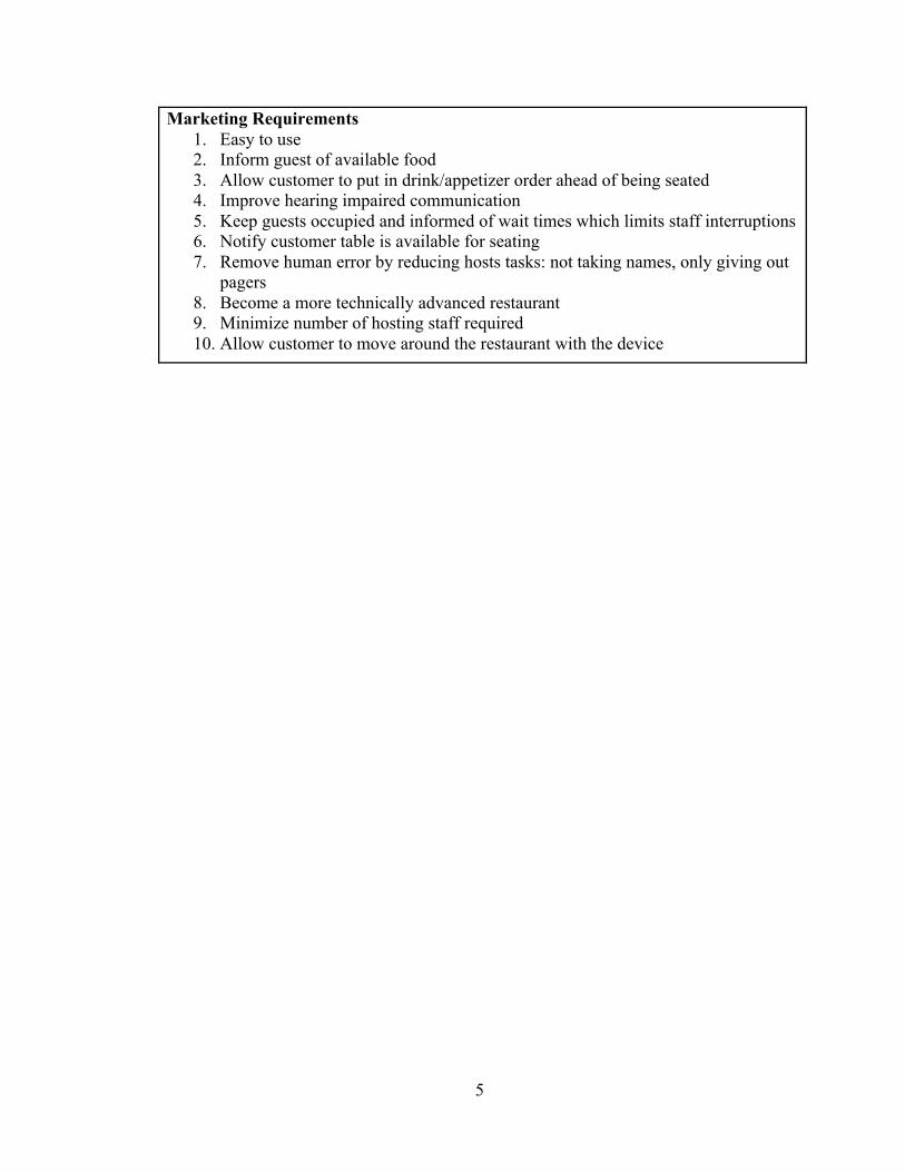
Marketing Requirements 1. Easy to use 2. Inform guest of available food 3. Allow customer to put in drink/appetizer order ahead of being seated 4. Improve hearing impaired communication 5. Keep guests occupied and informed of wait times which limits staff interruptions 6. Notify customer table is available for seating 7. Remove human error by reducing hosts tasks: not taking names, only giving out
pagers 8. Become a more technically advanced restaurant 9. Minimize number of hosting staff required 10. Allow customer to move around the restaurant with the device
[DT08]
3
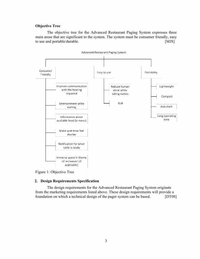
Objective Tree The objective tree for the Advanced Restaurant Paging System expresses three
main areas that are significant to the system. The system must be consumer friendly, easy to use and portable/durable. [MJS]
Figure 1: Objective Tree 2. Design Requirements Specification
The design requirements for the Advanced Restaurant Paging System originate from the marketing requirements listed above. These design requirements will provide a foundation on which a technical design of the pager system can be based. [DT08]
4
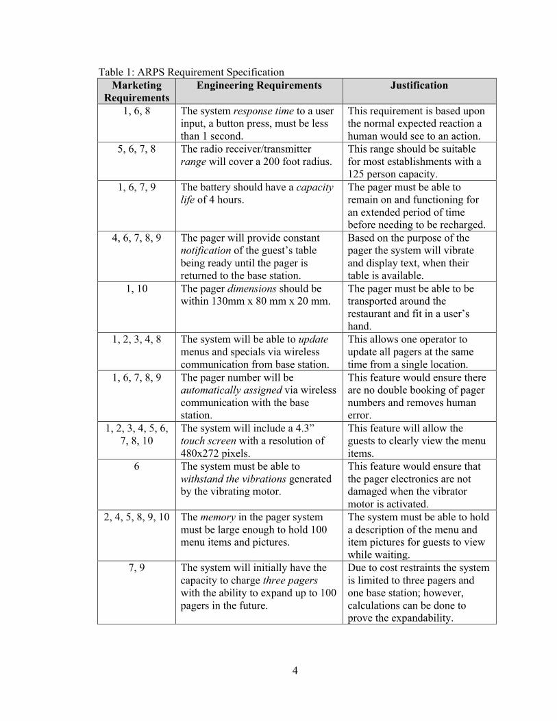
Table 1: ARPS Requirement Specification Marketing
Requirements Engineering Requirements Justification
1, 6, 8 The system response time to a user input, a button press, must be less than 1 second.
This requirement is based upon the normal expected reaction a human would see to an action.
5, 6, 7, 8 The radio receiver/transmitter range will cover a 200 foot radius.
This range should be suitable for most establishments with a 125 person capacity.
1, 6, 7, 9 The battery should have a capacity life of 4 hours.
The pager must be able to remain on and functioning for an extended period of time before needing to be recharged.
4, 6, 7, 8, 9 The pager will provide constant notification of the guest’s table being ready until the pager is returned to the base station.
Based on the purpose of the pager the system will vibrate and display text, when their table is available.
1, 10 The pager dimensions should be within 130mm x 80 mm x 20 mm.
The pager must be able to be transported around the restaurant and fit in a user’s hand.
1, 2, 3, 4, 8 The system will be able to update menus and specials via wireless communication from base station.
This allows one operator to update all pagers at the same time from a single location.
1, 6, 7, 8, 9 The pager number will be automatically assigned via wireless communication with the base station.
This feature would ensure there are no double booking of pager numbers and removes human error.
1, 2, 3, 4, 5, 6, 7, 8, 10
The system will include a 4.3” touch screen with a resolution of 480x272 pixels.
This feature will allow the guests to clearly view the menu items.
6 The system must be able to withstand the vibrations generated by the vibrating motor.
This feature would ensure that the pager electronics are not damaged when the vibrator motor is activated.
2, 4, 5, 8, 9, 10 The memory in the pager system must be large enough to hold 100 menu items and pictures.
The system must be able to hold a description of the menu and item pictures for guests to view while waiting.
7, 9 The system will initially have the capacity to charge three pagers with the ability to expand up to 100 pagers in the future.
Due to cost restraints the system is limited to three pagers and one base station; however, calculations can be done to prove the expandability.
5
Marketing Requirements 1. Easy to use 2. Inform guest of available food 3. Allow customer to put in drink/appetizer order ahead of being seated 4. Improve hearing impaired communication 5. Keep guests occupied and informed of wait times which limits staff interruptions 6. Notify customer table is available for seating 7. Remove human error by reducing hosts tasks: not taking names, only giving out
pagers 8. Become a more technically advanced restaurant 9. Minimize number of hosting staff required 10. Allow customer to move around the restaurant with the device
6
3. Accepted Technical Design A. Hardware Modules
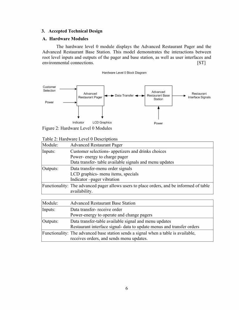
The hardware level 0 module displays the Advanced Restaurant Pager and the Advanced Restaurant Base Station. This model demonstrates the interactions between root level inputs and outputs of the pager and base station, as well as user interfaces and environmental connections. [ST]
Figure 2: Hardware Level 0 Modules Table 2: Hardware Level 0 Descriptions Module: Advanced Restaurant Pager Inputs: Customer selections- appetizers and drinks choices Power- energy to charge pager Data transfer- table available signals and menu updates Outputs: Data transfer-menu order signals
LCD graphics- menu items, specials Indicator –pager vibration
Functionality: The advanced pager allows users to place orders, and be informed of table availability.
Module: Advanced Restaurant Base Station Inputs: Data transfer- receive order
Power-energy to operate and change pagers Outputs: Data transfer-table available signal and menu updates
Restaurant interface signal- data to update menus and transfer orders Functionality: The advanced base station sends a signal when a table is available,
receives orders, and sends menu updates.

7
The Level 1 Hardware diagram depicts a more in-depth view of the components needed for the advanced pager system. This diagram illustrates the connections between components and the different elements needed so a customer can order an appetizer or drink. [ST]
Figure 3: Hardware Level 1 Advanced Pager Modules Table 3: Hardware Level 1 Advanced Pager Descriptions Module: Power Supply Inputs: Power- Energy to operate pager during undocked state Outputs: DC energy to the pager components Functionality: The power supply will allow for energy to be transferred, when docked, to
the pager and stored for later use. The power supply will convert the incoming energy into the required DC levels needed by the elements of the advanced pager.
Module: LCD/Touch Screen Inputs: Display commands from the microprocessor
Power to operate the display Customer selections
Outputs: Selections made by the customer to the microprocessor Graphical display information for the customer
Functionality: The LCD/touch screen will allow a patron to view the menu, make selections for their order, be informed of specials, and be alerted when their table is available.

8
Module: Microprocessor Inputs: Selections made by guests from the LCD/touch screen
Power to operate Received signals from the radio Tx/Rx
Outputs: Transmitted signals to the radio Tx/Rx Vibrate command to the vibrator motor Display commands to the LCD touch screen
Functionality: The microprocessor will handle all incoming/outgoing data and control all devices in the pager.
Module: Vibration Motor Inputs: Commands from the microprocessor Outputs: Vibrate Functionality: The vibration motor will vibrate with variable duration and intensity
depending on the incoming command to notify a customer. Module: Radio Tx/Rx Inputs: Commands and data, orders, from the microprocessor
Receive data from the base station Outputs: Transmit data to the base station
Send commands and data received to the microprocessor Functionality: The radio Tx/Rx will transmit and receive data between the base station
and the pager.
9
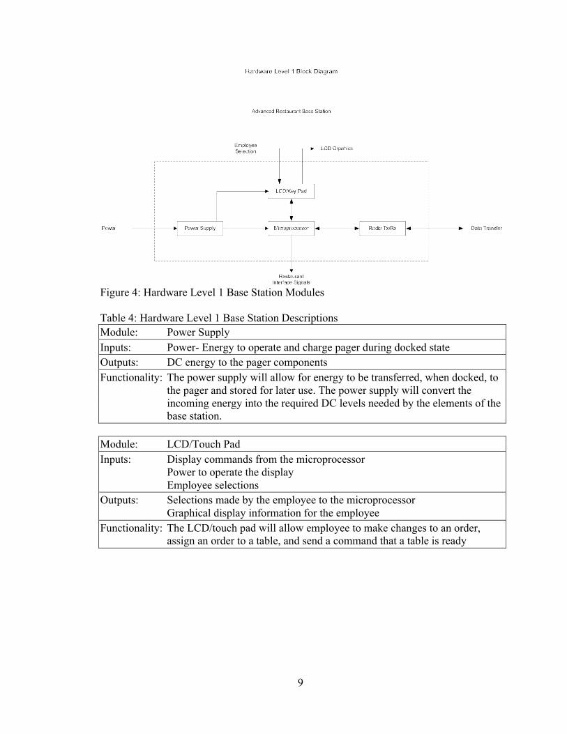
Figure 4: Hardware Level 1 Base Station Modules Table 4: Hardware Level 1 Base Station Descriptions Module: Power Supply Inputs: Power- Energy to operate and charge pager during docked state Outputs: DC energy to the pager components Functionality: The power supply will allow for energy to be transferred, when docked, to
the pager and stored for later use. The power supply will convert the incoming energy into the required DC levels needed by the elements of the base station.
Module: LCD/Touch Pad Inputs: Display commands from the microprocessor
Power to operate the display Employee selections
Outputs: Selections made by the employee to the microprocessor Graphical display information for the employee
Functionality: The LCD/touch pad will allow employee to make changes to an order, assign an order to a table, and send a command that a table is ready
10
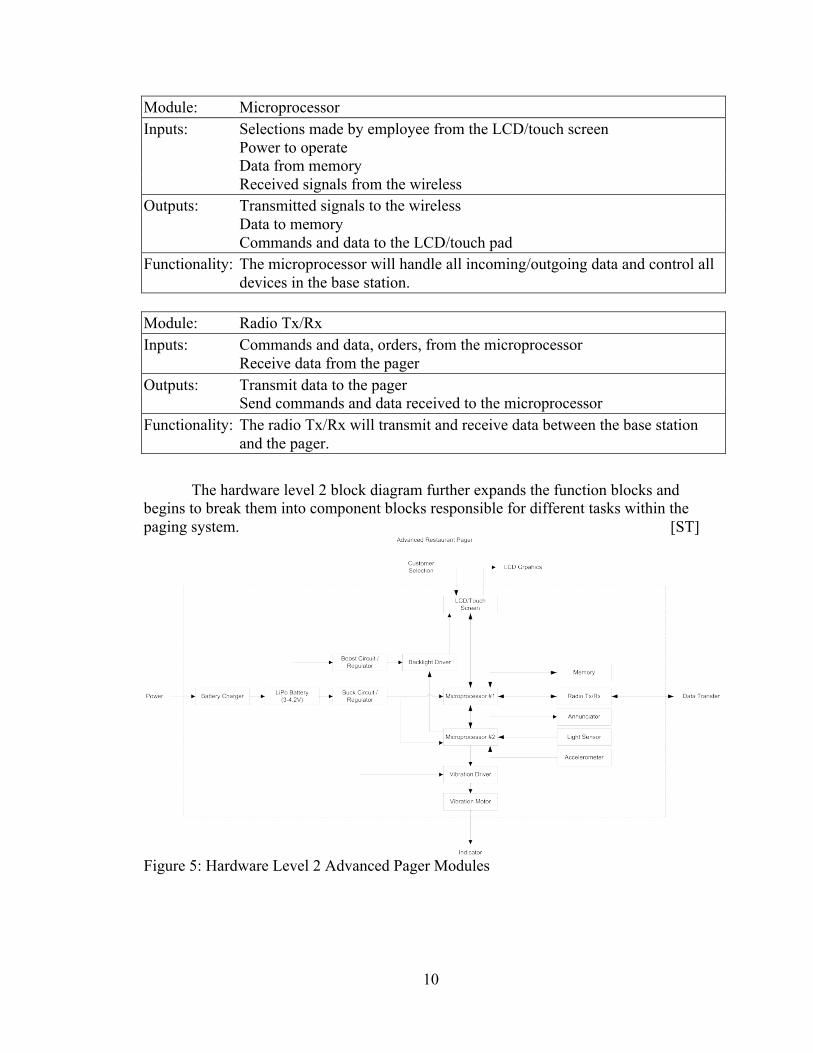
Module: Microprocessor Inputs: Selections made by employee from the LCD/touch screen
Power to operate Data from memory Received signals from the wireless
Outputs: Transmitted signals to the wireless Data to memory Commands and data to the LCD/touch pad
Functionality: The microprocessor will handle all incoming/outgoing data and control all devices in the base station.
Module: Radio Tx/Rx Inputs: Commands and data, orders, from the microprocessor
Receive data from the pager Outputs: Transmit data to the pager
Send commands and data received to the microprocessor Functionality: The radio Tx/Rx will transmit and receive data between the base station
and the pager.
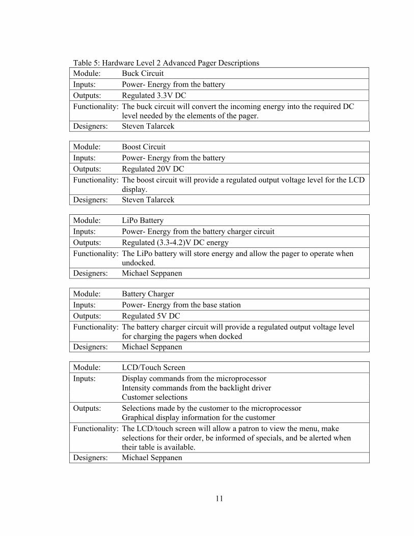
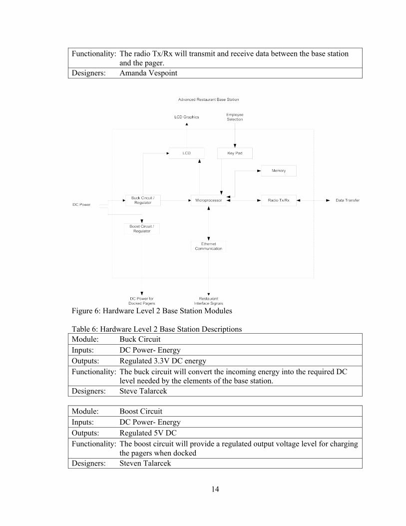
The hardware level 2 block diagram further expands the function blocks and begins to break them into component blocks responsible for different tasks within the paging system. [ST]
Figure 5: Hardware Level 2 Advanced Pager Modules
11
Table 5: Hardware Level 2 Advanced Pager Descriptions Module: Buck Circuit Inputs: Power- Energy from the battery Outputs: Regulated 3.3V DC Functionality: The buck circuit will convert the incoming energy into the required DC
level needed by the elements of the pager. Designers: Steven Talarcek Module: Boost Circuit Inputs: Power- Energy from the battery Outputs: Regulated 20V DC Functionality: The boost circuit will provide a regulated output voltage level for the LCD
display. Designers: Steven Talarcek Module: LiPo Battery Inputs: Power- Energy from the battery charger circuit Outputs: Regulated (3.3-4.2)V DC energy Functionality: The LiPo battery will store energy and allow the pager to operate when
undocked. Designers: Michael Seppanen Module: Battery Charger Inputs: Power- Energy from the base station Outputs: Regulated 5V DC Functionality: The battery charger circuit will provide a regulated output voltage level
for charging the pagers when docked Designers: Michael Seppanen Module: LCD/Touch Screen Inputs: Display commands from the microprocessor
Intensity commands from the backlight driver Customer selections
Outputs: Selections made by the customer to the microprocessor Graphical display information for the customer
Functionality: The LCD/touch screen will allow a patron to view the menu, make selections for their order, be informed of specials, and be alerted when their table is available.
Designers: Michael Seppanen
12
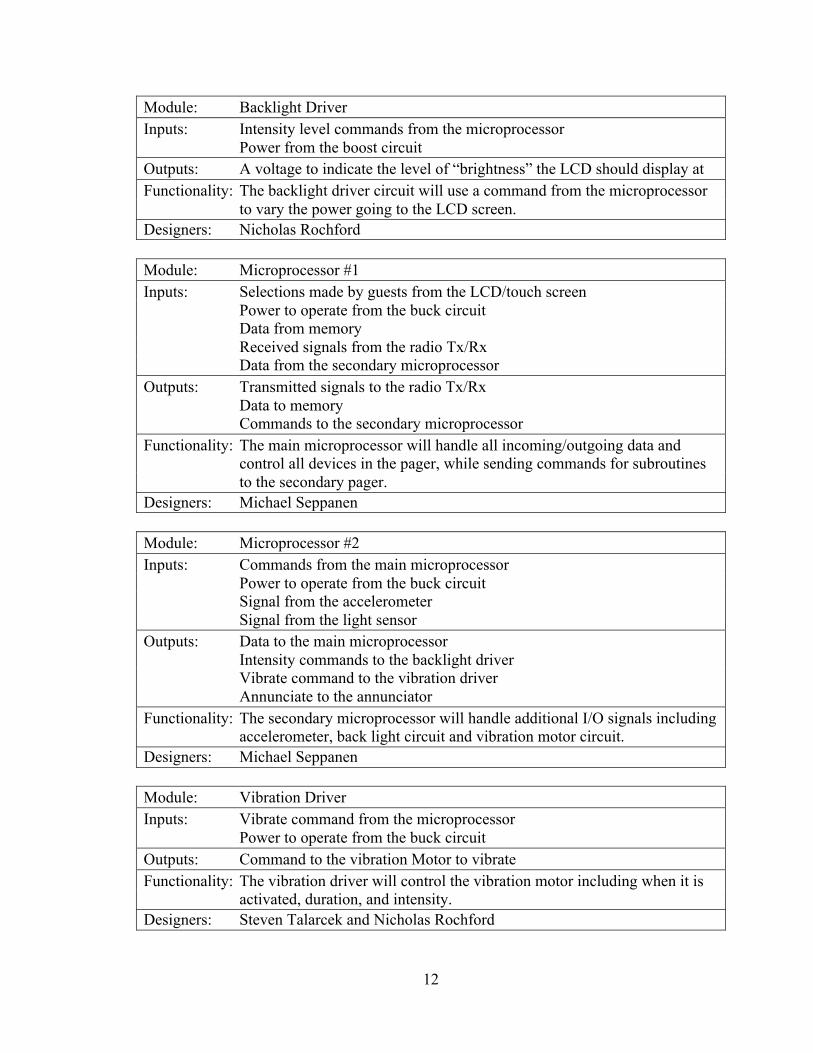
Module: Backlight Driver Inputs: Intensity level commands from the microprocessor
Power from the boost circuit Outputs: A voltage to indicate the level of “brightness” the LCD should display at Functionality: The backlight driver circuit will use a command from the microprocessor
to vary the power going to the LCD screen. Designers: Nicholas Rochford Module: Microprocessor #1 Inputs: Selections made by guests from the LCD/touch screen
Power to operate from the buck circuit Data from memory Received signals from the radio Tx/Rx Data from the secondary microprocessor
Outputs: Transmitted signals to the radio Tx/Rx Data to memory Commands to the secondary microprocessor
Functionality: The main microprocessor will handle all incoming/outgoing data and control all devices in the pager, while sending commands for subroutines to the secondary pager.
Designers: Michael Seppanen Module: Microprocessor #2 Inputs: Commands from the main microprocessor
Power to operate from the buck circuit Signal from the accelerometer Signal from the light sensor
Outputs: Data to the main microprocessor Intensity commands to the backlight driver Vibrate command to the vibration driver Annunciate to the annunciator
Functionality: The secondary microprocessor will handle additional I/O signals including accelerometer, back light circuit and vibration motor circuit.
Designers: Michael Seppanen Module: Vibration Driver Inputs: Vibrate command from the microprocessor
Power to operate from the buck circuit Outputs: Command to the vibration Motor to vibrate Functionality: The vibration driver will control the vibration motor including when it is
activated, duration, and intensity. Designers: Steven Talarcek and Nicholas Rochford
13
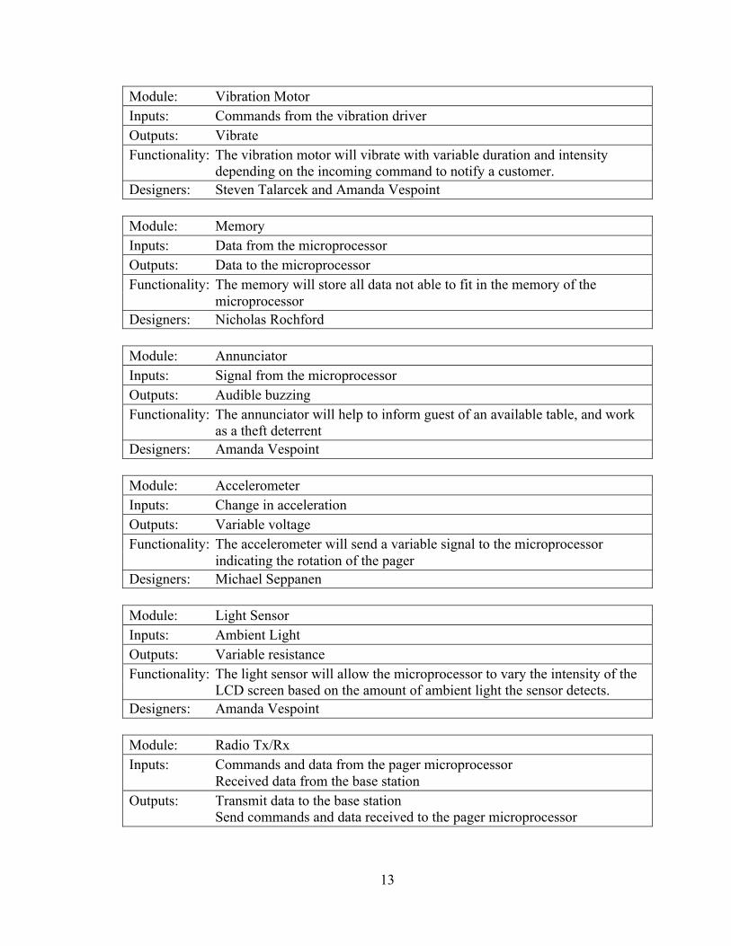
Module: Vibration Motor Inputs: Commands from the vibration driver Outputs: Vibrate Functionality: The vibration motor will vibrate with variable duration and intensity
depending on the incoming command to notify a customer. Designers: Steven Talarcek and Amanda Vespoint Module: Memory Inputs: Data from the microprocessor Outputs: Data to the microprocessor Functionality: The memory will store all data not able to fit in the memory of the
microprocessor Designers: Nicholas Rochford Module: Annunciator Inputs: Signal from the microprocessor Outputs: Audible buzzing Functionality: The annunciator will help to inform guest of an available table, and work
as a theft deterrent Designers: Amanda Vespoint Module: Accelerometer Inputs: Change in acceleration Outputs: Variable voltage Functionality: The accelerometer will send a variable signal to the microprocessor
indicating the rotation of the pager Designers: Michael Seppanen Module: Light Sensor Inputs: Ambient Light Outputs: Variable resistance Functionality: The light sensor will allow the microprocessor to vary the intensity of the
LCD screen based on the amount of ambient light the sensor detects. Designers: Amanda Vespoint Module: Radio Tx/Rx Inputs: Commands and data from the pager microprocessor
Received data from the base station Outputs: Transmit data to the base station
Send commands and data received to the pager microprocessor
14
Functionality: The radio Tx/Rx will transmit and receive data between the base station and the pager.
Designers: Amanda Vespoint
Figure 6: Hardware Level 2 Base Station Modules Table 6: Hardware Level 2 Base Station Descriptions Module: Buck Circuit Inputs: DC Power- Energy Outputs: Regulated 3.3V DC energy Functionality: The buck circuit will convert the incoming energy into the required DC
level needed by the elements of the base station. Designers: Steve Talarcek Module: Boost Circuit Inputs: DC Power- Energy Outputs: Regulated 5V DC Functionality: The boost circuit will provide a regulated output voltage level for charging
the pagers when docked Designers: Steven Talarcek
15
Module: LCD Inputs: Display commands from the microprocessor
Power to operate the display Outputs: Graphical display information for the employee Functionality: The LCD will allow employee to see changes made to a pager and see
assignments of tables to pagers. Designers: Michael Seppanen Module: Key Pad Inputs: Employee selections on the pad Outputs: Selections made by the employee to the microprocessor Functionality: The key pad will allow employees to call pagers when tables are ready and
assign an order to a table Designers: Nicholas Rochford Module: Microprocessor Inputs: Selections made by employee from the key pad
Power to operate Data from memory Received signals from the radio Tx/Rx
Outputs: Signals to be transmitted by radio Tx/Rx Data to memory Commands and data to the LCD screen Signals and data to the Ethernet communication
Functionality: The microprocessor will handle all incoming/outgoing data and control all devices in the base station.
Designers: Michael Seppanen Module: Memory Inputs: Data from the base station microprocessor Outputs: Data to the base station microprocessor Functionality: The memory will store all data not able to fit in the memory of the
microprocessor Designers: Nicholas Rochford Module: Ethernet Communication Inputs: Signals and data from the restaurant Outputs: Signals and data to the restaurant Functionality: The Ethernet communication module will allow for communication
between the base station and a restaurant. It will allow for updating of the menu and for transmitting orders.
Designers: Nicholas Rochford
16
Module: Radio Tx/Rx Inputs: Commands and data from the base station microprocessor
Received data from the pager Outputs: Transmit data to the pager
Send commands and data received to the base station microprocessor Functionality: The radio Tx/Rx will transmit and receive data between the base station
and the pager. Designers: Amanda Vespoint B. Hardware Calculations The amount of power necessary for the pager to function is dependent upon each component. The approximate current draw of each of the major components was found in their data sheets. Since all the parts of the pager will not be active the whole time a more realistic power calculation was performed by estimating how much each part will be active. This decreased the power required from 1300mW to 880mW as seen in Table 7.
Table 7: Estimated Power Requirements for Pager Pager Voltage (V) Current (mA) Power (mW) %active Power actual (mW) Processor 3.3 20 66 100 66 Backlight 20 32 640 80 512 Accelerometer 3.3 1 3.3 100 3.3 Vibrating Motor 3.3 120 396 1 3.96 LCD 3.3 30 99 100 99 Radio 3.3 30 99 50 49.5 Total 1303.3 733.76 From the total power the required capacity of the battery can be calculated by knowing that the battery should last four hours. Using I×hr = hr×P/V gets a value of 0.793Ahr = 0.73376W×4hr/3.7V so therefore the battery has to have a capacity of at least 0.8Ah to last 4 hours. The amount of power necessary for the base station to operate continuously will be dependent upon each component that makes the base station up as well as the number of pagers charging at any given time. With all 100 pagers charging at one time and the pagers containing 0.85Ah batteries the total power of the system will be about 425W. Due to this high amount of power that would only be required if every pager needed to be charged the pagers will have a priority based charging method to limit the number of pagers charging at any given time. This charging method will allow a 5V 5A power supply to charge seven pagers at a time. [NR, MJS, ST]
17
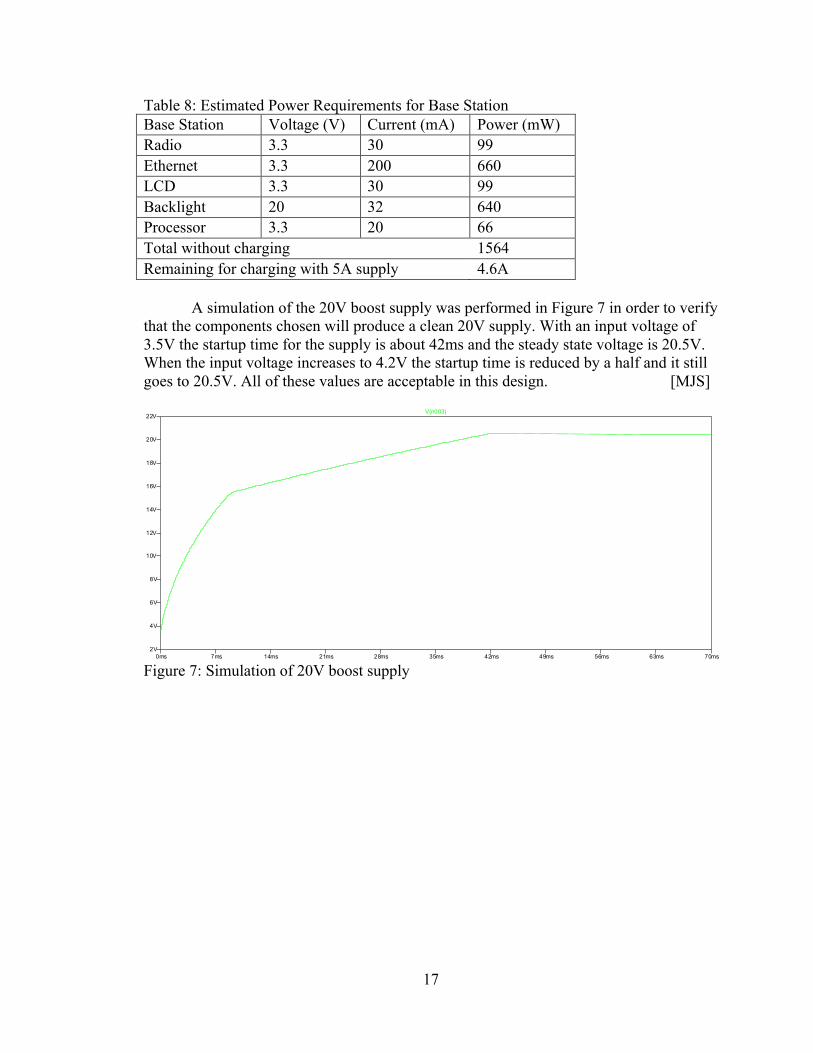
Table 8: Estimated Power Requirements for Base Station Base Station Voltage (V) Current (mA) Power (mW) Radio 3.3 30 99 Ethernet 3.3 200 660 LCD 3.3 30 99 Backlight 20 32 640 Processor 3.3 20 66 Total without charging 1564 Remaining for charging with 5A supply 4.6A A simulation of the 20V boost supply was performed in Figure 7 in order to verify that the components chosen will produce a clean 20V supply. With an input voltage of 3.5V the startup time for the supply is about 42ms and the steady state voltage is 20.5V. When the input voltage increases to 4.2V the startup time is reduced by a half and it still goes to 20.5V. All of these values are acceptable in this design. [MJS]
Figure 7: Simulation of 20V boost supply
0ms 7ms 14ms 21ms 28ms 35ms 42ms 49ms 56ms 63ms 70ms2V
4V
6V
8V
10V
12V
14V
16V
18V
20V
22VV(n003)
18
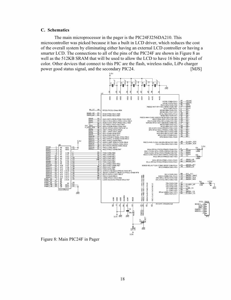
C. Schematics The main microprocessor in the pager is the PIC24FJ256DA210. This
microcontroller was picked because it has a built in LCD driver, which reduces the cost of the overall system by eliminating either having an external LCD controller or having a smarter LCD. The connections to all of the pins of the PIC24F are shown in Figure 8 as well as the 512KB SRAM that will be used to allow the LCD to have 16 bits per pixel of color. Other devices that connect to this PIC are the flash, wireless radio, LiPo charger power good status signal, and the secondary PIC24. [MJS]
Figure 8: Main PIC24F in Pager
19
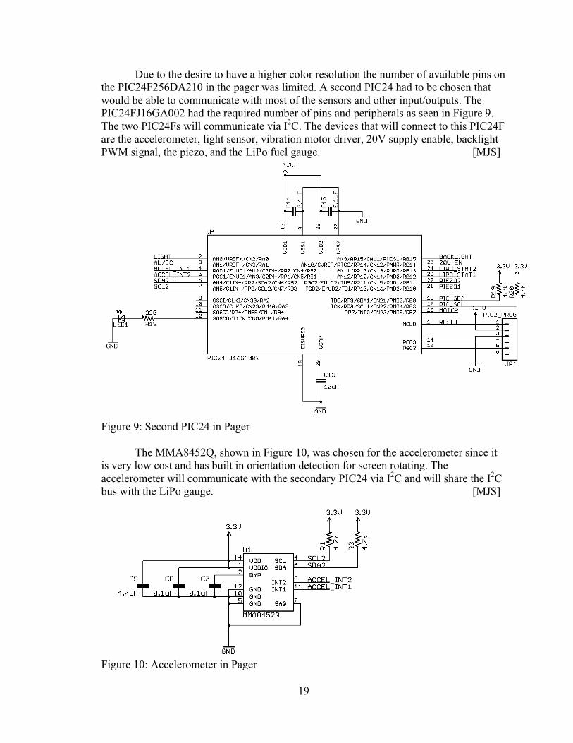
Due to the desire to have a higher color resolution the number of available pins on the PIC24F256DA210 in the pager was limited. A second PIC24 had to be chosen that would be able to communicate with most of the sensors and other input/outputs. The PIC24FJ16GA002 had the required number of pins and peripherals as seen in Figure 9. The two PIC24Fs will communicate via I2C. The devices that will connect to this PIC24F are the accelerometer, light sensor, vibration motor driver, 20V supply enable, backlight PWM signal, the piezo, and the LiPo fuel gauge. [MJS]
Figure 9: Second PIC24 in Pager
The MMA8452Q, shown in Figure 10, was chosen for the accelerometer since it is very low cost and has built in orientation detection for screen rotating. The accelerometer will communicate with the secondary PIC24 via I2C and will share the I2C bus with the LiPo gauge. [MJS]
Figure 10: Accelerometer in Pager
20
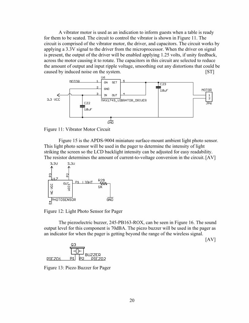
A vibrator motor is used as an indication to inform guests when a table is ready for them to be seated. The circuit to control the vibrator is shown in Figure 11. The circuit is comprised of the vibrator motor, the driver, and capacitors. The circuit works by applying a 3.3V signal to the driver from the microprocessor. When the driver on signal is present, the output of the driver will be enabled applying 1.25 volts, if unity feedback, across the motor causing it to rotate. The capacitors in this circuit are selected to reduce the amount of output and input ripple voltage, smoothing out any distortions that could be caused by induced noise on the system. [ST]
Figure 11: Vibrator Motor Circuit
Figure 15 is the APDS-9004 miniature surface-mount ambient light photo sensor. This light photo sensor will be used in the pager to determine the intensity of light striking the screen so the LCD backlight intensity can be adjusted for easy readability. The resistor determines the amount of current-to-voltage conversion in the circuit. [AV]
Figure 12: Light Photo Sensor for Pager The piezoelectric buzzer, 245-PB163-ROX, can be seen in Figure 16. The sound output level for this component is 70dBA. The piezo buzzer will be used in the pager as an indicator for when the pager is getting beyond the range of the wireless signal. [AV]
Figure 13: Piezo Buzzer for Pager
21
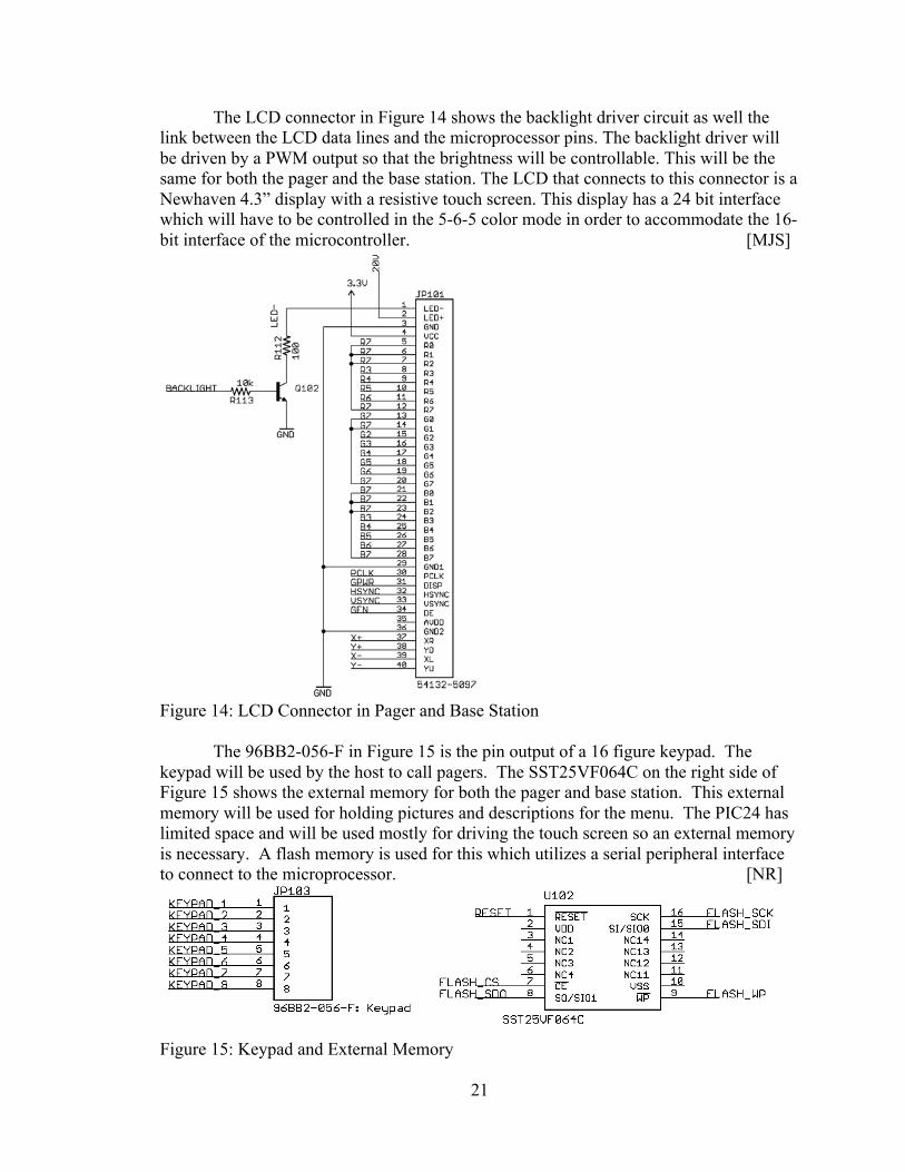
The LCD connector in Figure 14 shows the backlight driver circuit as well the link between the LCD data lines and the microprocessor pins. The backlight driver will be driven by a PWM output so that the brightness will be controllable. This will be the same for both the pager and the base station. The LCD that connects to this connector is a Newhaven 4.3” display with a resistive touch screen. This display has a 24 bit interface which will have to be controlled in the 5-6-5 color mode in order to accommodate the 16-bit interface of the microcontroller. [MJS]
Figure 14: LCD Connector in Pager and Base Station
The 96BB2-056-F in Figure 15 is the pin output of a 16 figure keypad. The keypad will be used by the host to call pagers. The SST25VF064C on the right side of Figure 15 shows the external memory for both the pager and base station. This external memory will be used for holding pictures and descriptions for the menu. The PIC24 has limited space and will be used mostly for driving the touch screen so an external memory is necessary. A flash memory is used for this which utilizes a serial peripheral interface to connect to the microprocessor. [NR]
Figure 15: Keypad and External Memory
22
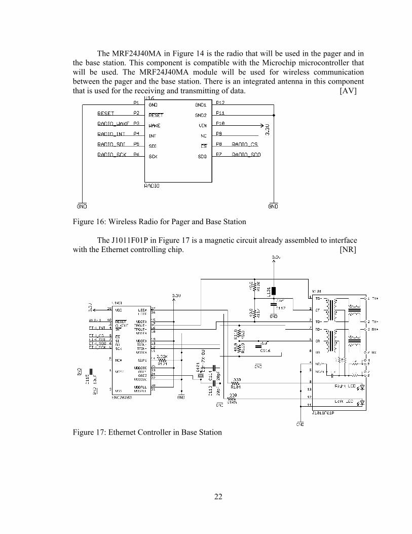
The MRF24J40MA in Figure 14 is the radio that will be used in the pager and in the base station. This component is compatible with the Microchip microcontroller that will be used. The MRF24J40MA module will be used for wireless communication between the pager and the base station. There is an integrated antenna in this component that is used for the receiving and transmitting of data. [AV]
Figure 16: Wireless Radio for Pager and Base Station
The J1011F01P in Figure 17 is a magnetic circuit already assembled to interface with the Ethernet controlling chip. [NR]
Figure 17: Ethernet Controller in Base Station
23
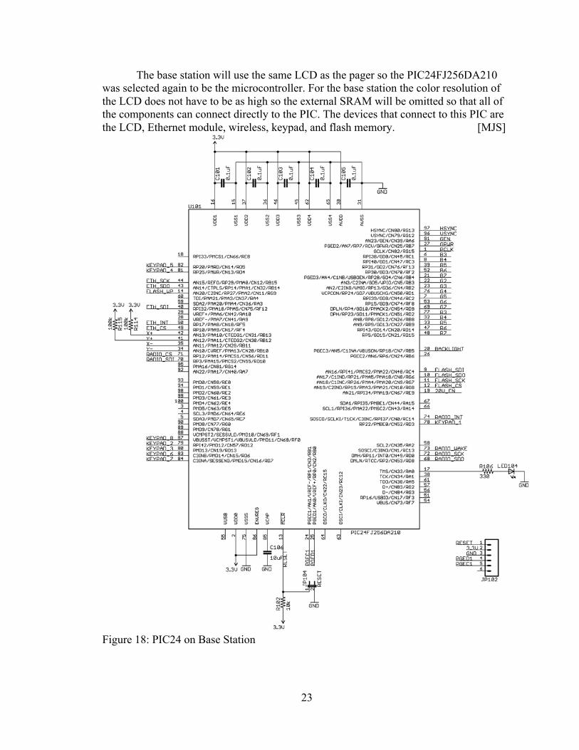
The base station will use the same LCD as the pager so the PIC24FJ256DA210 was selected again to be the microcontroller. For the base station the color resolution of the LCD does not have to be as high so the external SRAM will be omitted so that all of the components can connect directly to the PIC. The devices that connect to this PIC are the LCD, Ethernet module, wireless, keypad, and flash memory. [MJS]
Figure 18: PIC24 on Base Station
24
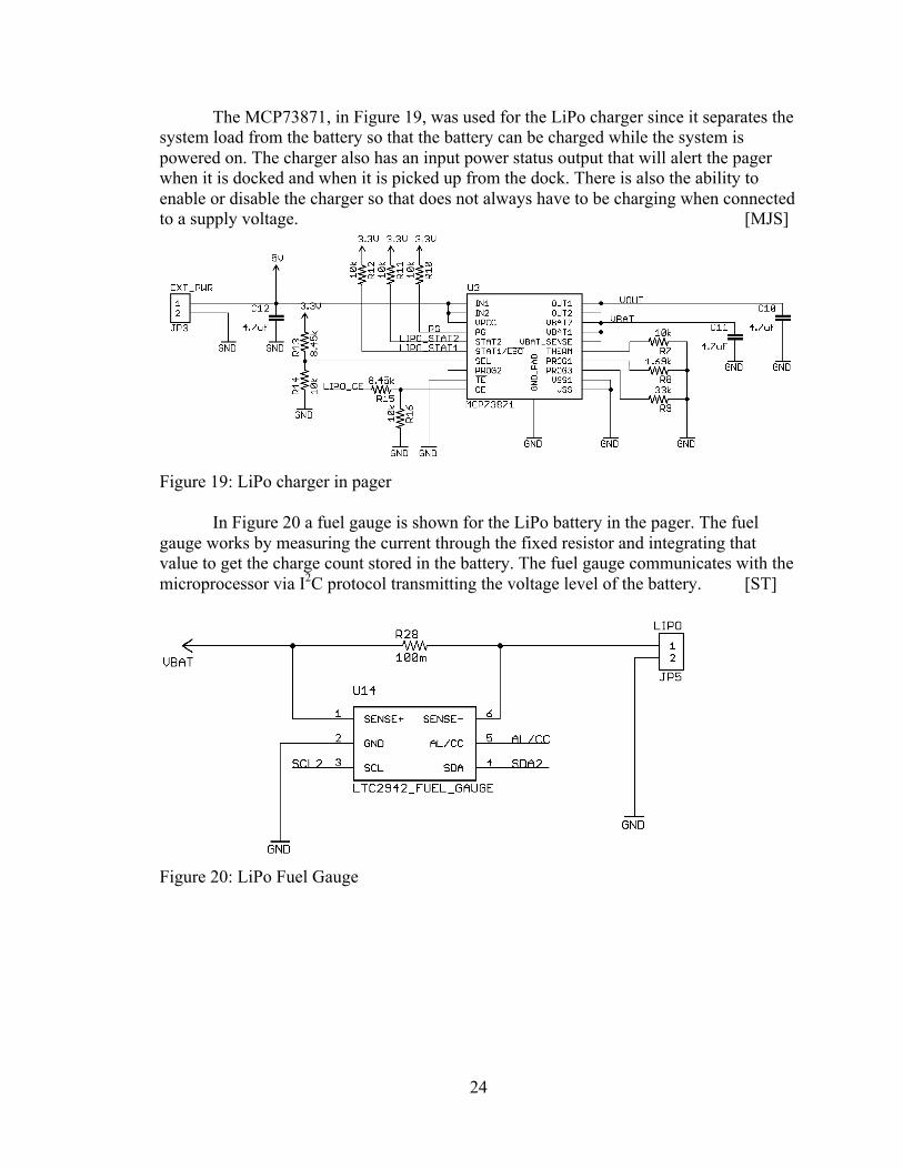
The MCP73871, in Figure 19, was used for the LiPo charger since it separates the system load from the battery so that the battery can be charged while the system is powered on. The charger also has an input power status output that will alert the pager when it is docked and when it is picked up from the dock. There is also the ability to enable or disable the charger so that does not always have to be charging when connected to a supply voltage. [MJS]
Figure 19: LiPo charger in pager
In Figure 20 a fuel gauge is shown for the LiPo battery in the pager. The fuel gauge works by measuring the current through the fixed resistor and integrating that value to get the charge count stored in the battery. The fuel gauge communicates with the microprocessor via I2C protocol transmitting the voltage level of the battery. [ST]
Figure 20: LiPo Fuel Gauge
25
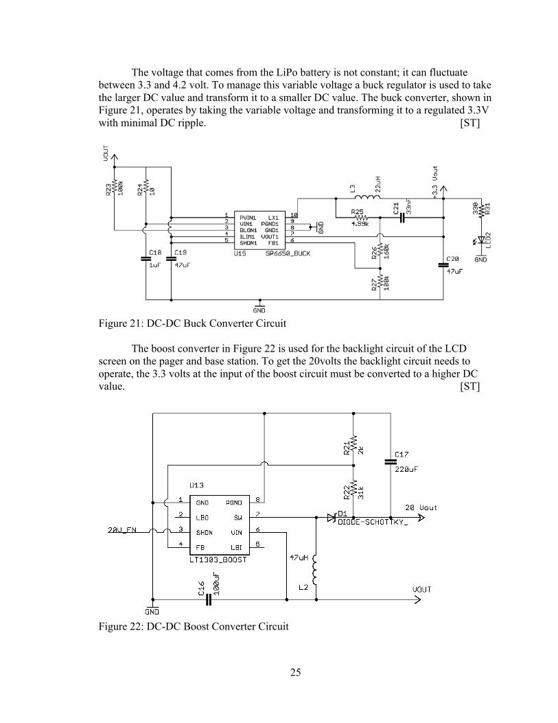
The voltage that comes from the LiPo battery is not constant; it can fluctuate between 3.3 and 4.2 volt. To manage this variable voltage a buck regulator is used to take the larger DC value and transform it to a smaller DC value. The buck converter, shown in Figure 21, operates by taking the variable voltage and transforming it to a regulated 3.3V with minimal DC ripple. [ST]
Figure 21: DC-DC Buck Converter Circuit The boost converter in Figure 22 is used for the backlight circuit of the LCD screen on the pager and base station. To get the 20volts the backlight circuit needs to operate, the 3.3 volts at the input of the boost circuit must be converted to a higher DC value. [ST]
Figure 22: DC-DC Boost Converter Circuit
26
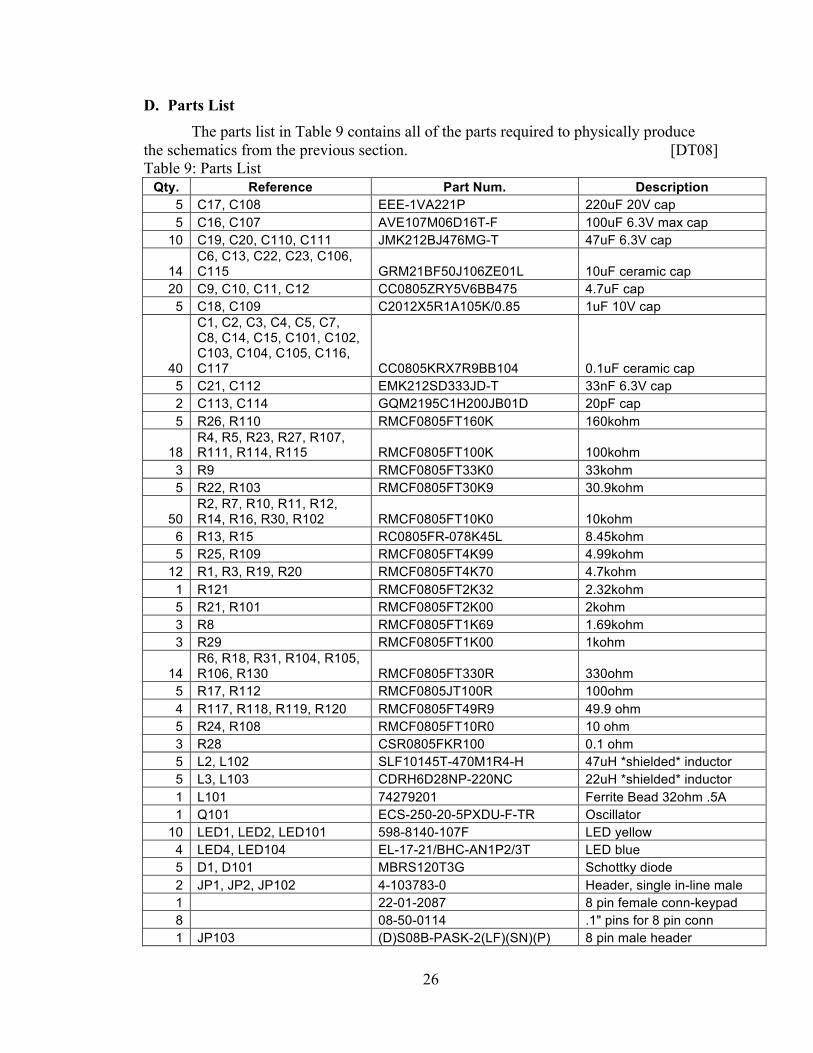
D. Parts List The parts list in Table 9 contains all of the parts required to physically produce
the schematics from the previous section. [DT08] Table 9: Parts List
Qty. Reference Part Num. Description 5 C17, C108 EEE-1VA221P 220uF 20V cap 5 C16, C107 AVE107M06D16T-F 100uF 6.3V max cap
10 C19, C20, C110, C111 JMK212BJ476MG-T 47uF 6.3V cap
14 C6, C13, C22, C23, C106, C115 GRM21BF50J106ZE01L 10uF ceramic cap
20 C9, C10, C11, C12 CC0805ZRY5V6BB475 4.7uF cap 5 C18, C109 C2012X5R1A105K/0.85 1uF 10V cap
40
C1, C2, C3, C4, C5, C7, C8, C14, C15, C101, C102, C103, C104, C105, C116, C117 CC0805KRX7R9BB104 0.1uF ceramic cap
5 C21, C112 EMK212SD333JD-T 33nF 6.3V cap 2 C113, C114 GQM2195C1H200JB01D 20pF cap 5 R26, R110 RMCF0805FT160K 160kohm
18 R4, R5, R23, R27, R107, R111, R114, R115 RMCF0805FT100K 100kohm
3 R9 RMCF0805FT33K0 33kohm 5 R22, R103 RMCF0805FT30K9 30.9kohm
50 R2, R7, R10, R11, R12, R14, R16, R30, R102 RMCF0805FT10K0 10kohm
6 R13, R15 RC0805FR-078K45L 8.45kohm 5 R25, R109 RMCF0805FT4K99 4.99kohm
12 R1, R3, R19, R20 RMCF0805FT4K70 4.7kohm 1 R121 RMCF0805FT2K32 2.32kohm 5 R21, R101 RMCF0805FT2K00 2kohm 3 R8 RMCF0805FT1K69 1.69kohm 3 R29 RMCF0805FT1K00 1kohm
14 R6, R18, R31, R104, R105, R106, R130 RMCF0805FT330R 330ohm
5 R17, R112 RMCF0805JT100R 100ohm 4 R117, R118, R119, R120 RMCF0805FT49R9 49.9 ohm 5 R24, R108 RMCF0805FT10R0 10 ohm 3 R28 CSR0805FKR100 0.1 ohm 5 L2, L102 SLF10145T-470M1R4-H 47uH *shielded* inductor 5 L3, L103 CDRH6D28NP-220NC 22uH *shielded* inductor 1 L101 74279201 Ferrite Bead 32ohm .5A 1 Q101 ECS-250-20-5PXDU-F-TR Oscillator
10 LED1, LED2, LED101 598-8140-107F LED yellow 4 LED4, LED104 EL-17-21/BHC-AN1P2/3T LED blue 5 D1, D101 MBRS120T3G Schottky diode 2 JP1, JP2, JP102 4-103783-0 Header, single in-line male 1 22-01-2087 8 pin female conn-keypad 8 08-50-0114 .1" pins for 8 pin conn 1 JP103 (D)S08B-PASK-2(LF)(SN)(P) 8 pin male header

27
1 PAP-08V-S 8 pin female conn 8 JP3, JP6, JP105, JP106 S02B-PASK-2(LF)(SN)(P) 2 pin male header 8 PAP-02V-S(P) 2 pin female conn
24 SPHD-001T-P0.5 Pins for JST conn 3 JP5 S2B-PH-K-S(LF)(SN) 2 pin JST PH (LiPo) 4 JP4, JP101 54132-4097 LCD connector 1 X101 J1011F01P Pulse Jack 3 Q3 254-PB163-ROX Piezo 3 U5 IS61WV25616BLL-10TL 512kB SRAM 3 U4 PIC24FJ16GA002-I/SS Second PIC 3 U1 MMA8453QR1 MMA8453 (accelerometer) 4 U16, U106 MRF24J40MA Wireless 4 U7, U102 SST25VF064C-80-4I-SCE 8MB Flash 4 U6 MAX1749 Motor Driver 4 NHD-4.3-480272MF-ATXI#-T-1 4.3" TFT Touchscreen LCD
4 U2, U101 PIC24FJ256DA210-I/PT PIC24 - LCD controller/microchip
3 310-010 Motor 6 U15, U105 SP6650EU-L Buck 3 U3 MCP73871-2CCI/ML LiPo charger 4 U17 APDS-9004 Light sensor 1 U103 ENC28J60 Ethernet Controller 1 96BB2-056-F 16 Button Keypad 3 63450 LiPo battery 4.2V 850mAH 5 U13, U104 LT1303CS8#PBF Boost 3 U14 LTC2942CDCB#TRMPBF LiPo Gauge 5 Q2, Q102 MMBT2222A Transistor
28
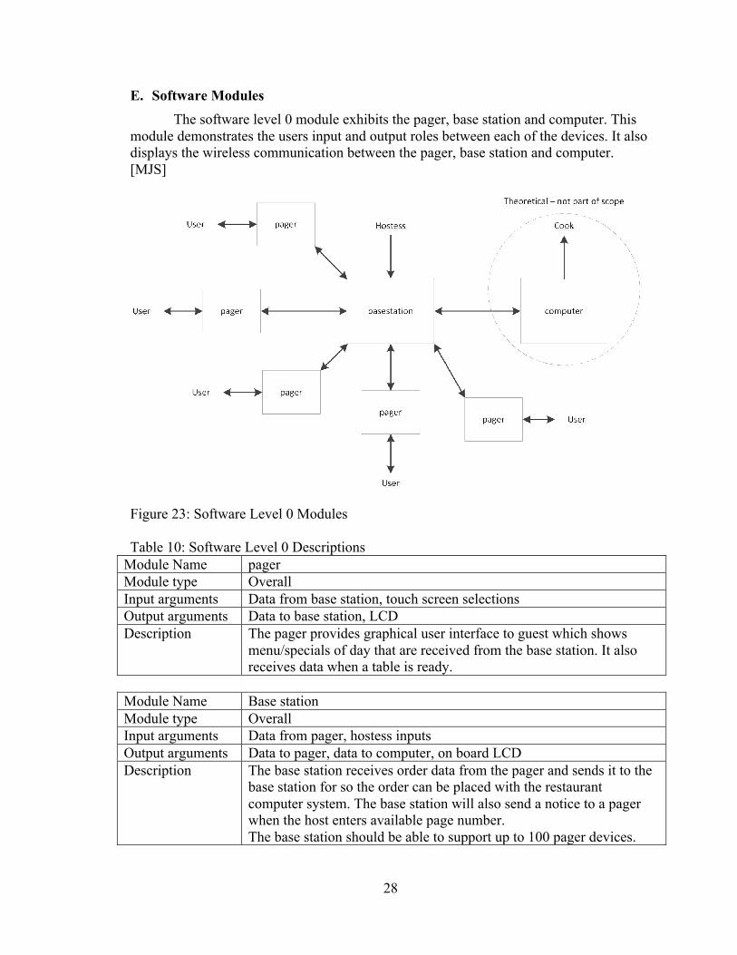
E. Software Modules The software level 0 module exhibits the pager, base station and computer. This module demonstrates the users input and output roles between each of the devices. It also displays the wireless communication between the pager, base station and computer. [MJS]
Figure 23: Software Level 0 Modules Table 10: Software Level 0 Descriptions
Module Name pager Module type Overall Input arguments Data from base station, touch screen selections Output arguments Data to base station, LCD Description The pager provides graphical user interface to guest which shows
menu/specials of day that are received from the base station. It also receives data when a table is ready.
Module Name Base station Module type Overall Input arguments Data from pager, hostess inputs Output arguments Data to pager, data to computer, on board LCD Description The base station receives order data from the pager and sends it to the
base station for so the order can be placed with the restaurant computer system. The base station will also send a notice to a pager when the host enters available page number. The base station should be able to support up to 100 pager devices.
29
Module Name Computer (Theoretical – not part of scope) Module type Overall Input arguments Data from base station Output arguments Data to base station Description The restaurant computer enters the order data received from base
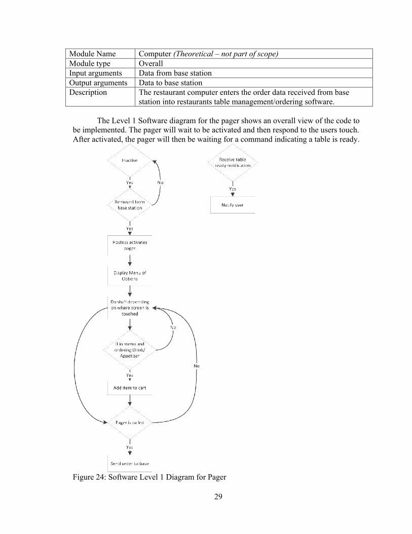
station into restaurants table management/ordering software. The Level 1 Software diagram for the pager shows an overall view of the code to
be implemented. The pager will wait to be activated and then respond to the users touch. After activated, the pager will then be waiting for a command indicating a table is ready.
Figure 24: Software Level 1 Diagram for Pager

30
Table 11: Level 1 Software Descriptions for Pager Module Name activate Input arguments Data from base station Output arguments None Description Waits for the pager to be undocked and then displays activation
menu. After activation settings are input the pager will show the user interface for the guest.
Module Name graphics Module type Graphics Input User touch Output Information on the LCD Description Takes the user touch input and figures out what should be on the
screen.
Module Name ordering Input arguments User touch Output arguments Data to base station Description When the user orders something the item will go into a cart that will
send the order once the pager is called.
Module Name table_ready Input arguments Data from base station Output arguments Notification to user Description Receives data from wireless that the table is ready and then notifies
the user by vibrating and displaying text.
31
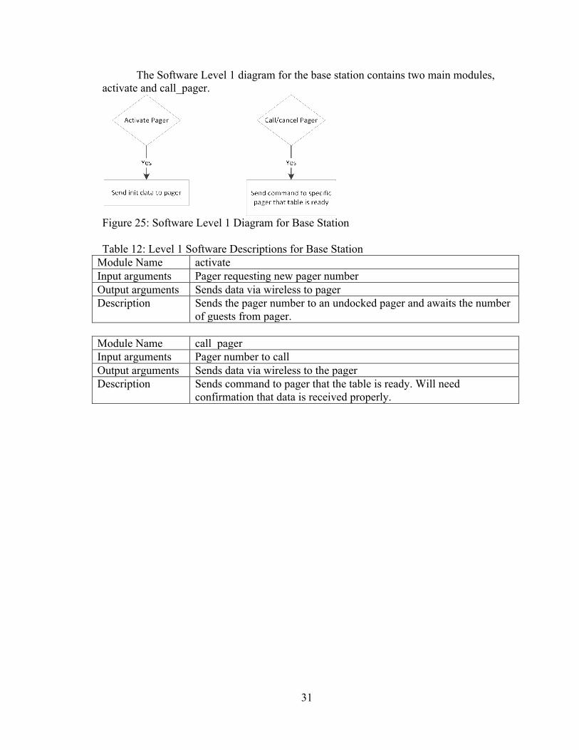
The Software Level 1 diagram for the base station contains two main modules, activate and call_pager.
Figure 25: Software Level 1 Diagram for Base Station Table 12: Level 1 Software Descriptions for Base Station
Module Name activate Input arguments Pager requesting new pager number Output arguments Sends data via wireless to pager Description Sends the pager number to an undocked pager and awaits the number
of guests from pager.
Module Name call_pager Input arguments Pager number to call Output arguments Sends data via wireless to the pager Description Sends command to pager that the table is ready. Will need
confirmation that data is received properly.
32
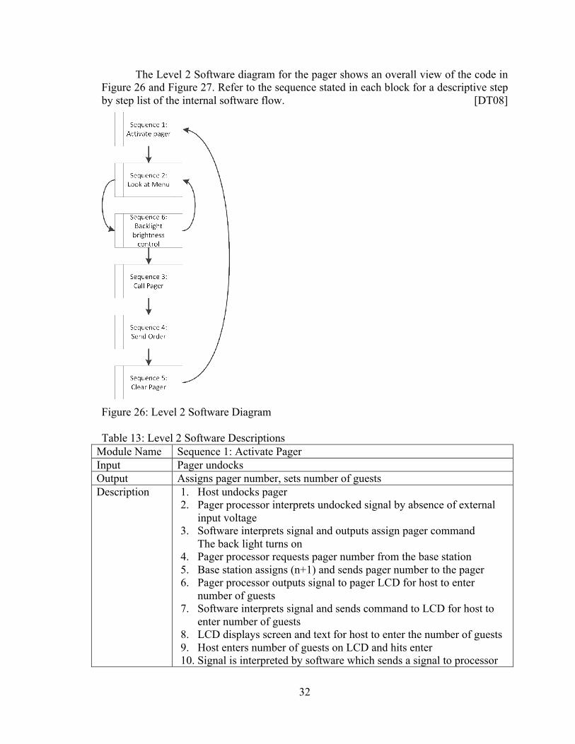
The Level 2 Software diagram for the pager shows an overall view of the code in Figure 26 and Figure 27. Refer to the sequence stated in each block for a descriptive step by step list of the internal software flow. [DT08]
Figure 26: Level 2 Software Diagram Table 13: Level 2 Software Descriptions
Module Name Sequence 1: Activate Pager Input Pager undocks Output Assigns pager number, sets number of guests Description 1. Host undocks pager
2. Pager processor interprets undocked signal by absence of external input voltage
3. Software interprets signal and outputs assign pager command The back light turns on
4. Pager processor requests pager number from the base station 5. Base station assigns (n+1) and sends pager number to the pager 6. Pager processor outputs signal to pager LCD for host to enter
number of guests 7. Software interprets signal and sends command to LCD for host to
enter number of guests 8. LCD displays screen and text for host to enter the number of guests 9. Host enters number of guests on LCD and hits enter 10. Signal is interpreted by software which sends a signal to processor
33
to transmit guest number to base station 11. The radio transmits data 12. Host selects guest interface button on pager LCD 13. Software interprets signal and outputs request to display menu 14. Pager processor sends command to display menu on LCD 15. Menu is displayed on LCD
Designer Nicholas Rochford, base station; Michael Seppanen, pager
Module Name Sequence 2: Look at Menu Input User touch Output Images and text on the display Description 1. Guests press button on the GUI to call menu
2. Press goes to processor 3. Processor calls up menu 4. Screen displays menu 5. If the guest wants to order something
a. Guest will press button to order item b. Signal will be sent to processor c. Processor will add item to order (after checking to make sure
the order is reasonable, e.g. A group of 2 tries to order 5 drinks and/or 4 appetizers, would be unreasonable)
Designer Michael Seppanen
Module Name Sequence 3: Call Pager Input Pager number on base station Output Pager notifies guest Description 1. Hostess presses Page on base station → Pager Number → Enter
2. Software interprets signal and sends the pager number to base station processor
3. Base processor sends command for radio transmitter to transmit page signal to pager Base processor sends signal for LCD to display pager ### has been paged
4. Software interprets signal and sends command to base radio to transmit to pager ### Software interprets signal and sends command for LCD to display pager paged
5. Base LCD displays pager ### paged Radio transmitter transmits signal to pager
6. Pager radio transmits confirmation of page command 7. Base station prompts host for a table number 8. Host enters table number where guest will be seated → Enter 9. Pager software interprets table ready signal and sends command to
processor to vibrate and display image 10. Pager processor sends command to vibrate and display table ready 11. Software interprets signal
34
12. LCD displays pager ready 13. Vibrator motor vibrates
Designer Nicholas Rochford, base station; Michael Seppanen, pager
Module Name Sequence 4: Order is sent back when called Input Pager called Output Order to radio transmitter Description 1. Pager processor sends command for radio transmitter to transmit
pager order to base station 2. Pager radio transmits order to base station 3. Base station processes the order by attaching the table number to the
order 4. Order is sent back to kitchen with table number user is being sat at
Designer Nicholas Rochford, base station; Michael Seppanen, pager
Module Name Sequence 5: Clearing Pager Input Pager called and then docked Output Clears pager for next activation Description 1. The guest hands the pager back to the hostess
2. The hostess places the pager on the charging stack 3. The pager senses the external input voltage 4. If the pager has not finished sending the order it will finish 5. Once the order is sent and received the pager automatically clears
the settings specific for the guest and the back light turns off Designer Michael Seppanen
Module Name Sequence 6: Back light brightness control Input Light sensor value Output Screen brightness Description 1. If the user has stopped interacting with the screen after a period of
time (e.g. 30s) a. The screen dims b. Wait for touch
2. While the screen is active a. Read light sensor (every so often)
i. If sensor reads brighter, make the screen brighter by increasing PWM
ii. If sensor reads lower, make the screen dimmer by decreasing PWM
iii. If sensor reads the same, keep brightness the same Designer Michael Seppanen
35
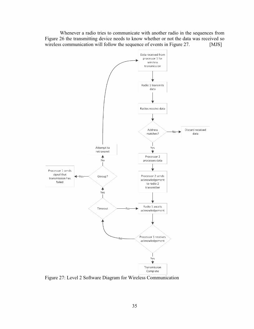
Whenever a radio tries to communicate with another radio in the sequences from Figure 26 the transmitting device needs to know whether or not the data was received so wireless communication will follow the sequence of events in Figure 27. [MJS]
Figure 27: Level 2 Software Diagram for Wireless Communication
36
Table 14: Level 2 Software Description for Wireless Communication Module Name Wireless Communication Input Data to radio Output Transmission successful or unsuccessful Description Any wireless communication will keep retransmitting until it is
acknowledged that the recipient has received the data or until it has tried a certain amount of times and then will return that the transmission has failed.
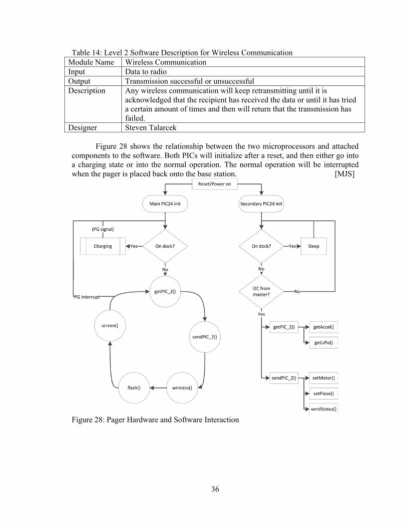
Designer Steven Talarcek Figure 28 shows the relationship between the two microprocessors and attached components to the software. Both PICs will initialize after a reset, and then either go into a charging state or into the normal operation. The normal operation will be interrupted when the pager is placed back onto the base station. [MJS]
Figure 28: Pager Hardware and Software Interaction
37
Table 15: Pager Hardware and Software Interaction Description Module Name Main PIC24 init Input Power up or reset Output Description Sets up all peripherals, LCD screen, etc. Designer Michael Seppanen
Module Name On dock? Input Power good signal from LiPo goes low via interrupt. Output Goes to charging algorithm described in Figure 30. Description While the pager is on the dock it will charge and wait to be removed from
the dock. The pager is in a low power state during this time and none of the peripherals on the secondary PIC are needed all the time so it will be able to sleep. The secondary PIC will need to be woken up occasionally to get the status of the LiPo if there are a lot of pagers that need to be charged.
Designer Michael Seppanen
Module Name Secondary PIC24 init Input Power up or reset Output Description Sets up all peripherals and sensors on the secondary PIC. Designer Michael Seppanen
Module Name getPIC_2() Input Output Values from second PIC attached components. Description Gets readings of sensors from the secondary PIC by talking via I2C to the
second PIC. This will return the values that the main PIC has requested, including the accelerometer and LiPo status.
Designer Michael Seppanen
Module Name sendPIC_2() Input Values to send to the secondary PIC attached components Output Description Sends required outputs to secondary PIC. This will control components
that the PIC has requested including the status, motor, and piezo. Designer Michael Seppanen
Module Name wireless() Input Data to wireless Output Data from wireless Description Sends or receives data to and from the radio transmitter. Follows Figure
26 and Figure 27 for when and how data is sent and received. Designer Michael Seppanen
38
Module Name flash() Input Output Description The flash is used to store the menu images. The images will be stored and
recalled using a Microchip image decode library. Designer Michael Seppanen
Module Name screen() Input Touch screen presses Output Graphics Description Sends data to the LCD. Receives resistive touch screen presses. This will
mostly be done using Microchip libraries. The display will respond to touches according to the GUI layout in Figure 32, Figure 33, and Figure 34.
Designer Michael Seppanen
Module Name getAccel() Input Output Accelerometer reading, if the accelerometer generated an interrupt that
information will be passed along to the main PIC Description Sends the required readings to the main PIC from the accelerometer. Designer Michael Seppanen
Module Name getLiPo() Input Output LiPo battery status Description Gets the LiPo battery status through the LiPo gauge and LiPo charger
statuses. These will allow the micro to know what the charge level is of the battery to inform the host and to decide its priority to be charged.
Designer Michael Seppanen
Module Name sendStatus() Input Output Status of Main PIC, screen has been idle, etc. Description Sends the various statuses of the main PIC mainly for the benefit of the
backlight controller. Also to be used as a heartbeat between the two processors so that they know the other is still running.
Designer Michael Seppanen
Module Name setMotor() Input Output Motor command Description Turns on or off the vibrator motor when the main PIC sends the
command to the secondary PIC which then activates the motor driver. Designer Michael Seppanen
39
Module Name setPiezo() Input Output Piezo command Description Makes the piezo operate when the main PIC sends the piezo activation
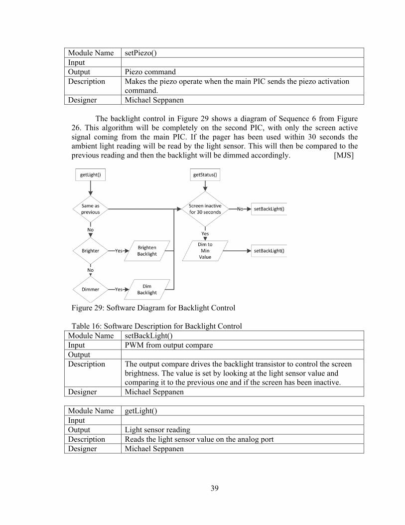
command. Designer Michael Seppanen The backlight control in Figure 29 shows a diagram of Sequence 6 from Figure 26. This algorithm will be completely on the second PIC, with only the screen active signal coming from the main PIC. If the pager has been used within 30 seconds the ambient light reading will be read by the light sensor. This will then be compared to the previous reading and then the backlight will be dimmed accordingly. [MJS]
Figure 29: Software Diagram for Backlight Control Table 16: Software Description for Backlight Control
Module Name setBackLight() Input PWM from output compare Output Description The output compare drives the backlight transistor to control the screen
brightness. The value is set by looking at the light sensor value and comparing it to the previous one and if the screen has been inactive.
Designer Michael Seppanen
Module Name getLight() Input Output Light sensor reading Description Reads the light sensor value on the analog port Designer Michael Seppanen
40
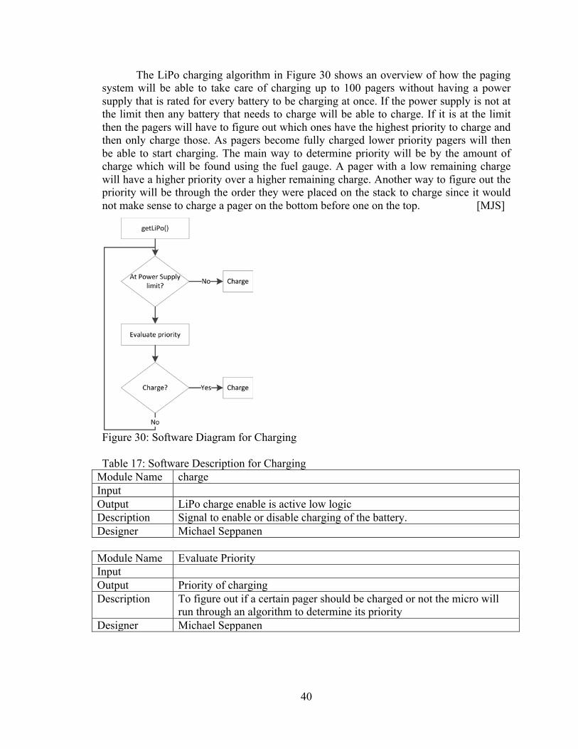
The LiPo charging algorithm in Figure 30 shows an overview of how the paging system will be able to take care of charging up to 100 pagers without having a power supply that is rated for every battery to be charging at once. If the power supply is not at the limit then any battery that needs to charge will be able to charge. If it is at the limit then the pagers will have to figure out which ones have the highest priority to charge and then only charge those. As pagers become fully charged lower priority pagers will then be able to start charging. The main way to determine priority will be by the amount of charge which will be found using the fuel gauge. A pager with a low remaining charge will have a higher priority over a higher remaining charge. Another way to figure out the priority will be through the order they were placed on the stack to charge since it would not make sense to charge a pager on the bottom before one on the top. [MJS]
Figure 30: Software Diagram for Charging Table 17: Software Description for Charging
Module Name charge Input Output LiPo charge enable is active low logic Description Signal to enable or disable charging of the battery. Designer Michael Seppanen
Module Name Evaluate Priority Input Output Priority of charging Description To figure out if a certain pager should be charged or not the micro will
run through an algorithm to determine its priority Designer Michael Seppanen
41
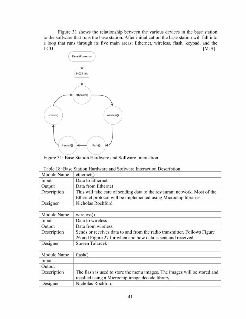
Figure 31 shows the relationship between the various devices in the base station to the software that runs the base station. After initialization the base station will fall into a loop that runs through its five main areas: Ethernet, wireless, flash, keypad, and the LCD. [MJS]
Figure 31: Base Station Hardware and Software Interaction Table 18: Base Station Hardware and Software Interaction Description
Module Name ethernet() Input Data to Ethernet Output Data from Ethernet Description This will take care of sending data to the restaurant network. Most of the
Ethernet protocol will be implemented using Microchip libraries. Designer Nicholas Rochford
Module Name wireless() Input Data to wireless Output Data from wireless Description Sends or receives data to and from the radio transmitter. Follows Figure
26 and Figure 27 for when and how data is sent and received. Designer Steven Talarcek
Module Name flash() Input Output Description The flash is used to store the menu images. The images will be stored and
recalled using a Microchip image decode library. Designer Nicholas Rochford
42
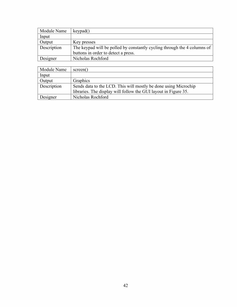
Module Name keypad() Input Output Key presses Description The keypad will be polled by constantly cycling through the 4 columns of
buttons in order to detect a press. Designer Nicholas Rochford
Module Name screen() Input Output Graphics Description Sends data to the LCD. This will mostly be done using Microchip
libraries. The display will follow the GUI layout in Figure 35. Designer Nicholas Rochford
43
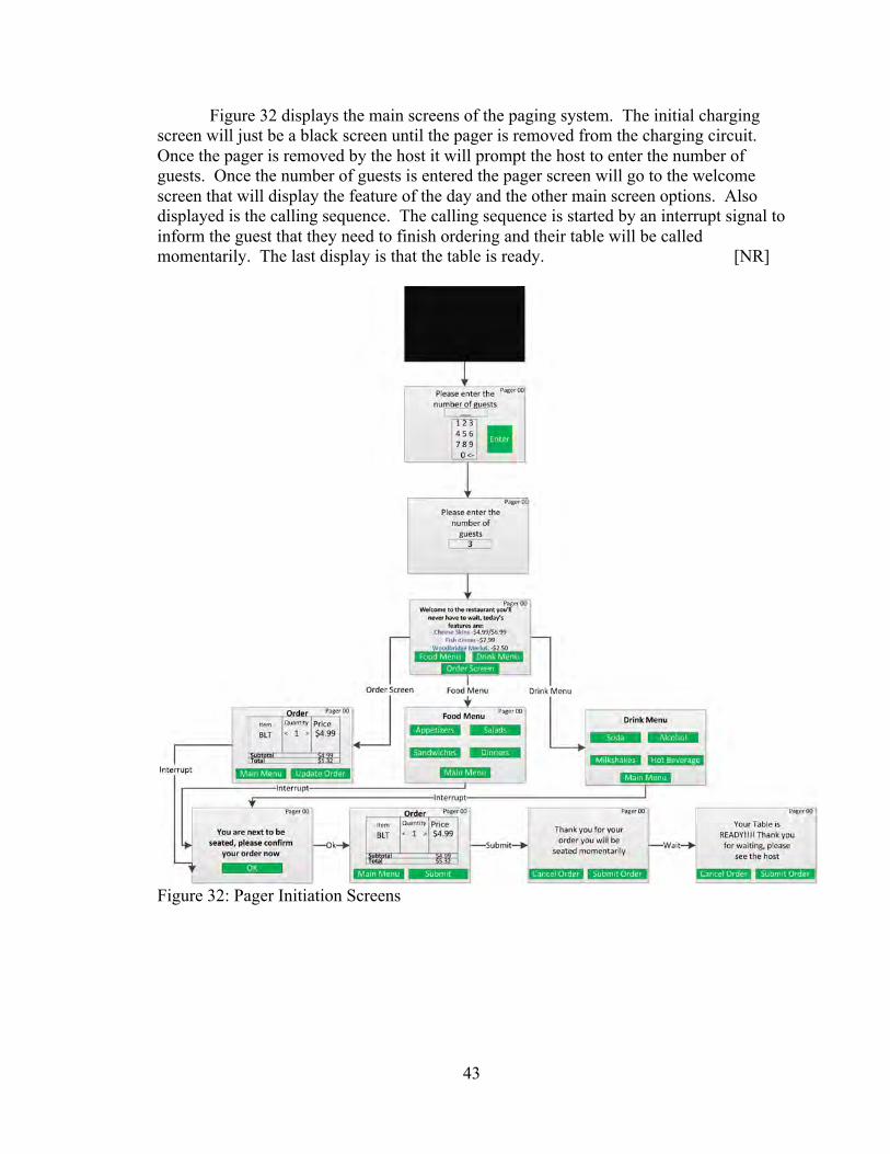
Figure 32 displays the main screens of the paging system. The initial charging screen will just be a black screen until the pager is removed from the charging circuit. Once the pager is removed by the host it will prompt the host to enter the number of guests. Once the number of guests is entered the pager screen will go to the welcome screen that will display the feature of the day and the other main screen options. Also displayed is the calling sequence. The calling sequence is started by an interrupt signal to inform the guest that they need to finish ordering and their table will be called momentarily. The last display is that the table is ready. [NR]
Figure 32: Pager Initiation Screens
44
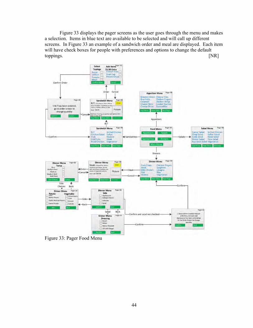
Figure 33 displays the pager screens as the user goes through the menu and makes a selection. Items in blue text are available to be selected and will call up different screens. In Figure 33 an example of a sandwich order and meal are displayed. Each item will have check boxes for people with preferences and options to change the default toppings. [NR]
Figure 33: Pager Food Menu
45
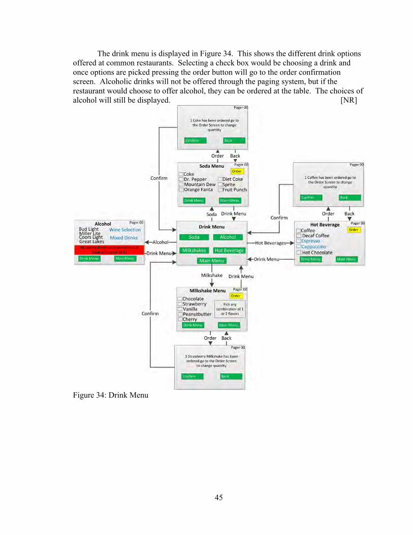
The drink menu is displayed in Figure 34. This shows the different drink options offered at common restaurants. Selecting a check box would be choosing a drink and once options are picked pressing the order button will go to the order confirmation screen. Alcoholic drinks will not be offered through the paging system, but if the restaurant would choose to offer alcohol, they can be ordered at the table. The choices of alcohol will still be displayed. [NR]
Figure 34: Drink Menu
46
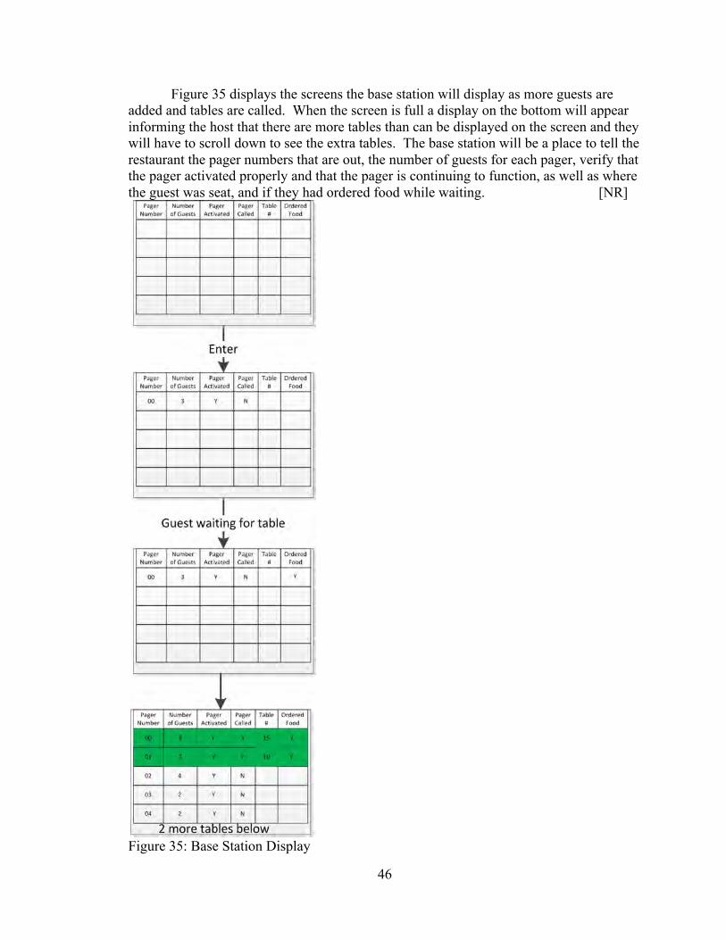
Figure 35 displays the screens the base station will display as more guests are added and tables are called. When the screen is full a display on the bottom will appear informing the host that there are more tables than can be displayed on the screen and they will have to scroll down to see the extra tables. The base station will be a place to tell the restaurant the pager numbers that are out, the number of guests for each pager, verify that the pager activated properly and that the pager is continuing to function, as well as where the guest was seat, and if they had ordered food while waiting. [NR]
Figure 35: Base Station Display
47
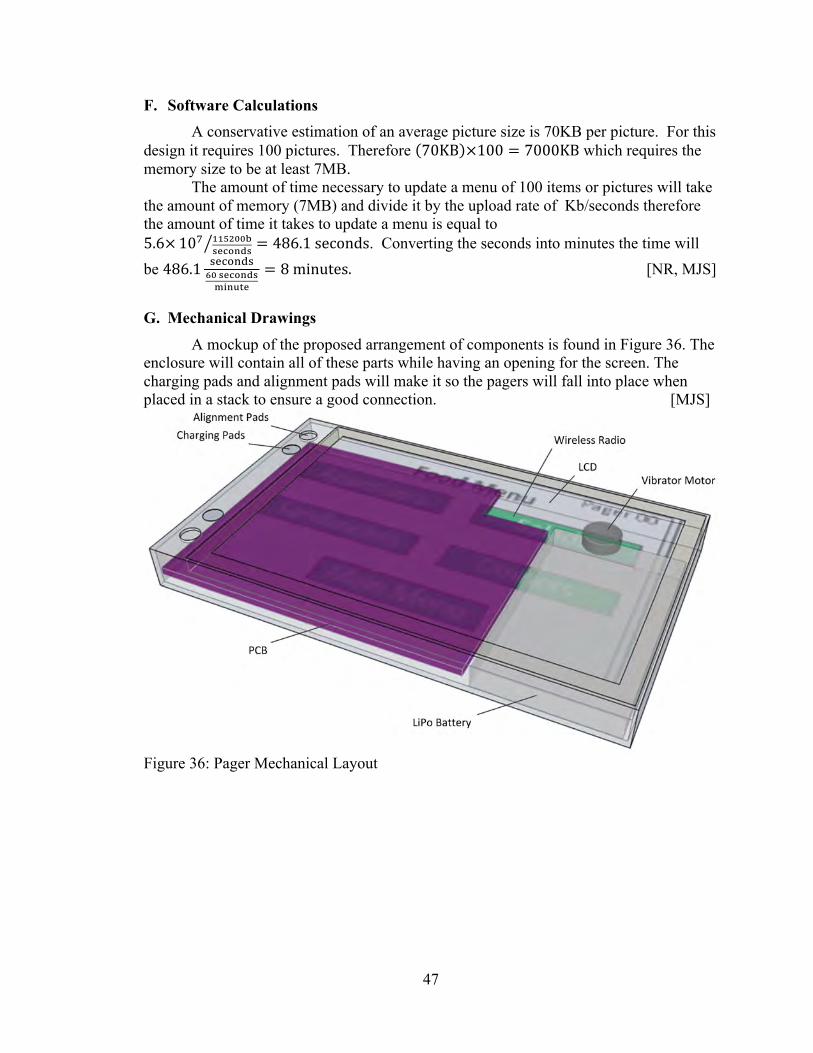
F. Software Calculations A conservative estimation of an average picture size is 70KB per picture. For this design it requires 100 pictures. Therefore 70KB ×100 = 7000KB which requires the memory size to be at least 7MB. The amount of time necessary to update a menu of 100 items or pictures will take the amount of memory (7MB) and divide it by the upload rate of Kb/seconds therefore the amount of time it takes to update a menu is equal to 5.6× 10! !!"#$$!
!"#$%&! = 486.1 seconds. Converting the seconds into minutes the time will be 486.1 !"#$%&!
!" !"#$%&!!"#$%&
= 8 minutes. [NR, MJS]
G. Mechanical Drawings A mockup of the proposed arrangement of components is found in Figure 36. The enclosure will contain all of these parts while having an opening for the screen. The charging pads and alignment pads will make it so the pagers will fall into place when placed in a stack to ensure a good connection. [MJS]
Figure 36: Pager Mechanical Layout
48
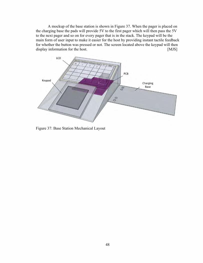
A mockup of the base station is shown in Figure 37. When the pager is placed on the charging base the pads will provide 5V to the first pager which will then pass the 5V to the next pager and so on for every pager that is in the stack. The keypad will be the main form of user input to make it easier for the host by providing instant tactile feedback for whether the button was pressed or not. The screen located above the keypad will then display information for the host. [MJS]
Figure 37: Base Station Mechanical Layout
49
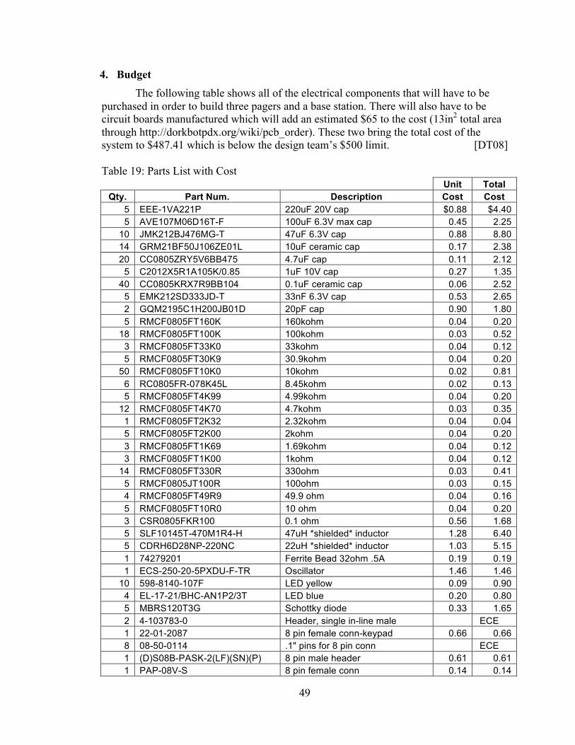
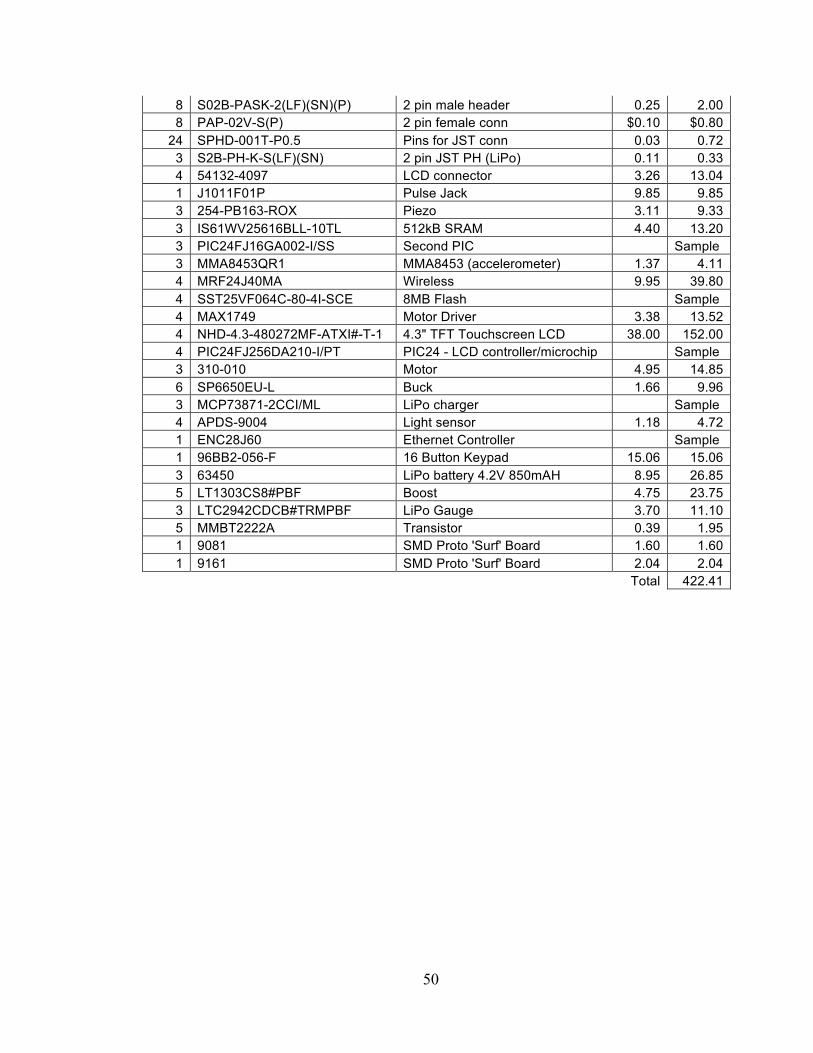
4. Budget The following table shows all of the electrical components that will have to be
purchased in order to build three pagers and a base station. There will also have to be circuit boards manufactured which will add an estimated $65 to the cost (13in2 total area through http://dorkbotpdx.org/wiki/pcb_order). These two bring the total cost of the system to $487.41 which is below the design team’s $500 limit. [DT08]
Table 19: Parts List with Cost
Unit Total
Qty. Part Num. Description Cost Cost 5 EEE-1VA221P 220uF 20V cap $0.88 $4.40 5 AVE107M06D16T-F 100uF 6.3V max cap 0.45 2.25
10 JMK212BJ476MG-T 47uF 6.3V cap 0.88 8.80 14 GRM21BF50J106ZE01L 10uF ceramic cap 0.17 2.38 20 CC0805ZRY5V6BB475 4.7uF cap 0.11 2.12
5 C2012X5R1A105K/0.85 1uF 10V cap 0.27 1.35 40 CC0805KRX7R9BB104 0.1uF ceramic cap 0.06 2.52
5 EMK212SD333JD-T 33nF 6.3V cap 0.53 2.65 2 GQM2195C1H200JB01D 20pF cap 0.90 1.80 5 RMCF0805FT160K 160kohm 0.04 0.20
18 RMCF0805FT100K 100kohm 0.03 0.52 3 RMCF0805FT33K0 33kohm 0.04 0.12 5 RMCF0805FT30K9 30.9kohm 0.04 0.20
50 RMCF0805FT10K0 10kohm 0.02 0.81 6 RC0805FR-078K45L 8.45kohm 0.02 0.13 5 RMCF0805FT4K99 4.99kohm 0.04 0.20
12 RMCF0805FT4K70 4.7kohm 0.03 0.35 1 RMCF0805FT2K32 2.32kohm 0.04 0.04 5 RMCF0805FT2K00 2kohm 0.04 0.20 3 RMCF0805FT1K69 1.69kohm 0.04 0.12 3 RMCF0805FT1K00 1kohm 0.04 0.12
14 RMCF0805FT330R 330ohm 0.03 0.41 5 RMCF0805JT100R 100ohm 0.03 0.15 4 RMCF0805FT49R9 49.9 ohm 0.04 0.16 5 RMCF0805FT10R0 10 ohm 0.04 0.20 3 CSR0805FKR100 0.1 ohm 0.56 1.68 5 SLF10145T-470M1R4-H 47uH *shielded* inductor 1.28 6.40 5 CDRH6D28NP-220NC 22uH *shielded* inductor 1.03 5.15 1 74279201 Ferrite Bead 32ohm .5A 0.19 0.19 1 ECS-250-20-5PXDU-F-TR Oscillator 1.46 1.46
10 598-8140-107F LED yellow 0.09 0.90 4 EL-17-21/BHC-AN1P2/3T LED blue 0.20 0.80 5 MBRS120T3G Schottky diode 0.33 1.65 2 4-103783-0 Header, single in-line male ECE 1 22-01-2087 8 pin female conn-keypad 0.66 0.66 8 08-50-0114 .1" pins for 8 pin conn ECE 1 (D)S08B-PASK-2(LF)(SN)(P) 8 pin male header 0.61 0.61 1 PAP-08V-S 8 pin female conn 0.14 0.14
50
8 S02B-PASK-2(LF)(SN)(P) 2 pin male header 0.25 2.00 8 PAP-02V-S(P) 2 pin female conn $0.10 $0.80
24 SPHD-001T-P0.5 Pins for JST conn 0.03 0.72 3 S2B-PH-K-S(LF)(SN) 2 pin JST PH (LiPo) 0.11 0.33 4 54132-4097 LCD connector 3.26 13.04 1 J1011F01P Pulse Jack 9.85 9.85 3 254-PB163-ROX Piezo 3.11 9.33 3 IS61WV25616BLL-10TL 512kB SRAM 4.40 13.20 3 PIC24FJ16GA002-I/SS Second PIC Sample 3 MMA8453QR1 MMA8453 (accelerometer) 1.37 4.11 4 MRF24J40MA Wireless 9.95 39.80 4 SST25VF064C-80-4I-SCE 8MB Flash Sample 4 MAX1749 Motor Driver 3.38 13.52 4 NHD-4.3-480272MF-ATXI#-T-1 4.3" TFT Touchscreen LCD 38.00 152.00 4 PIC24FJ256DA210-I/PT PIC24 - LCD controller/microchip Sample 3 310-010 Motor 4.95 14.85 6 SP6650EU-L Buck 1.66 9.96 3 MCP73871-2CCI/ML LiPo charger Sample 4 APDS-9004 Light sensor 1.18 4.72 1 ENC28J60 Ethernet Controller Sample 1 96BB2-056-F 16 Button Keypad 15.06 15.06 3 63450 LiPo battery 4.2V 850mAH 8.95 26.85 5 LT1303CS8#PBF Boost 4.75 23.75 3 LTC2942CDCB#TRMPBF LiPo Gauge 3.70 11.10 5 MMBT2222A Transistor 0.39 1.95 1 9081 SMD Proto 'Surf' Board 1.60 1.60 1 9161 SMD Proto 'Surf' Board 2.04 2.04
Total 422.41
51
5. Project Schedule Final Design Gantt
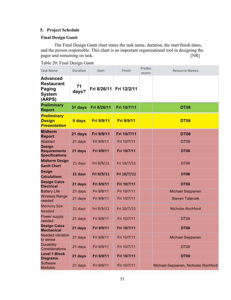
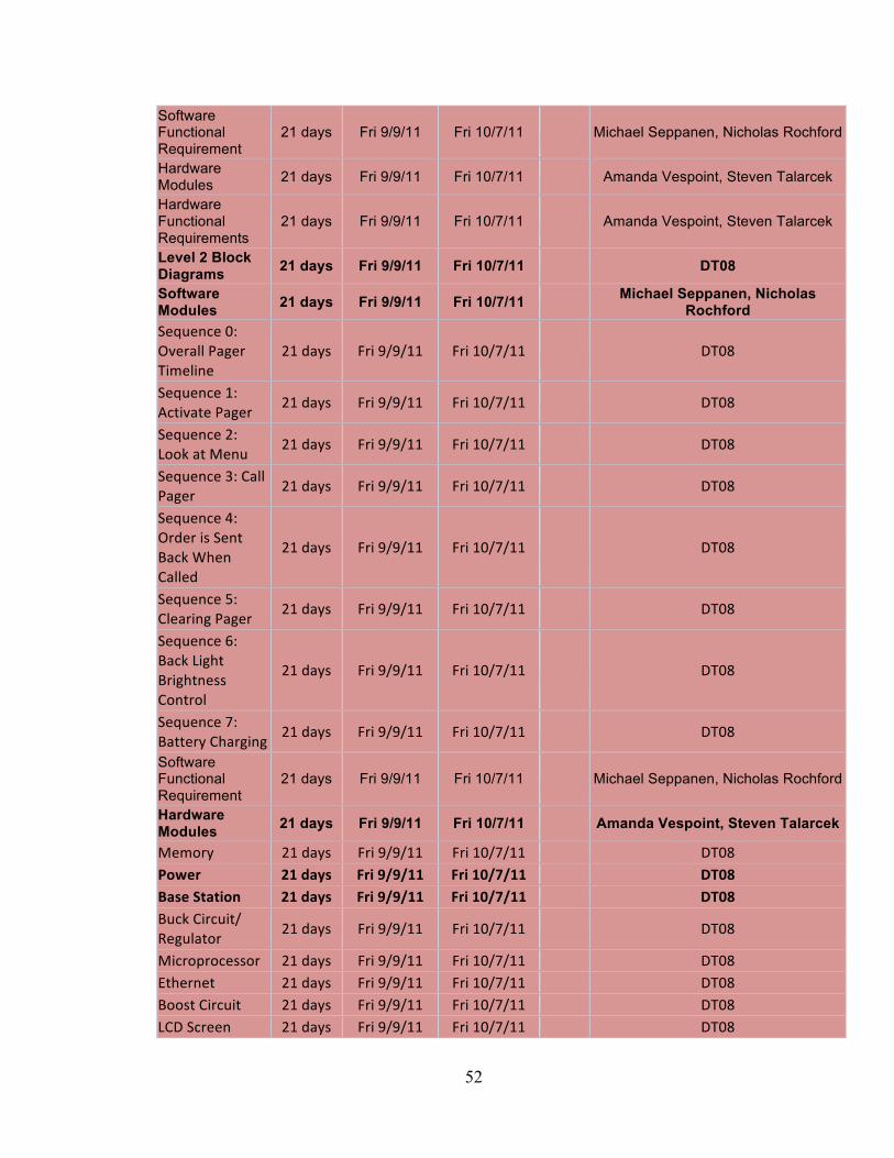
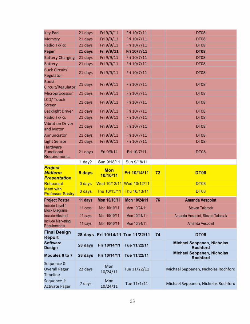
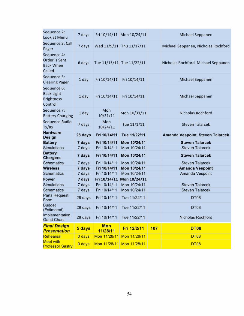
The Final Design Gantt chart states the task name, duration, the start/finish dates, and the person responsible. This chart is an important organizational tool in designing the pager and remaining on task. [NR] Table 20: Final Design Gantt Task Name Duration Start Finish Predec
essors Resource Names
Advanced Restaurant Paging System (ARPS)
71 days? Fri 8/26/11 Fri 12/2/11
Preliminary Report 31 days Fri 8/26/11 Fri 10/7/11 DT08
Preliminary Design Presentation
0 days Fri 9/9/11 Fri 9/9/11 DT08
Midterm Report 21 days Fri 9/9/11 Fri 10/7/11 DT08 Abstract 21 days Fri 9/9/11 Fri 10/7/11 DT08 Design Requirements Specifications
21 days Fri 9/9/11 Fri 10/7/11 DT08
Midterm Design Gantt Chart 21 days Fri 9/9/11 Fri 10/7/11
DT08
Design Calculations 21 days Fri 9/9/11 Fri 10/7/11
DT08
Design Calcs Electrical 21 days Fri 9/9/11 Fri 10/7/11 DT08
Battery Life 21 days Fri 9/9/11 Fri 10/7/11 Michael Seppanen Wireless Range needed 21 days Fri 9/9/11 Fri 10/7/11 Steven Talarcek
Memory Size Needed 21 days Fri 9/9/11 Fri 10/7/11
Nicholas Rochford
Power supply needed 21 days Fri 9/9/11 Fri 10/7/11 DT08
Design Calcs Mechanical 21 days Fri 9/9/11 Fri 10/7/11 DT08
Needed vibration to sense 21 days Fri 9/9/11 Fri 10/7/11 Michael Seppanen
Durability Considerations 21 days Fri 9/9/11 Fri 10/7/11 DT08
Level 1 Block Diagrams 21 days Fri 9/9/11 Fri 10/7/11 DT08
Software Modules 21 days Fri 9/9/11 Fri 10/7/11 Michael Seppanen, Nicholas Rochford
52
Software Functional Requirement
21 days Fri 9/9/11 Fri 10/7/11 Michael Seppanen, Nicholas Rochford
Hardware Modules 21 days Fri 9/9/11 Fri 10/7/11 Amanda Vespoint, Steven Talarcek
Hardware Functional Requirements
21 days Fri 9/9/11 Fri 10/7/11 Amanda Vespoint, Steven Talarcek
Level 2 Block Diagrams 21 days Fri 9/9/11 Fri 10/7/11 DT08
Software Modules 21 days Fri 9/9/11 Fri 10/7/11
Michael Seppanen, Nicholas Rochford
Sequence 0: Overall Pager Timeline
21 days Fri 9/9/11 Fri 10/7/11
DT08
Sequence 1: Activate Pager 21 days Fri 9/9/11 Fri 10/7/11
DT08
Sequence 2: Look at Menu 21 days Fri 9/9/11 Fri 10/7/11
DT08
Sequence 3: Call Pager 21 days Fri 9/9/11 Fri 10/7/11
DT08
Sequence 4: Order is Sent Back When Called
21 days Fri 9/9/11 Fri 10/7/11
DT08
Sequence 5: Clearing Pager 21 days Fri 9/9/11 Fri 10/7/11
DT08
Sequence 6: Back Light Brightness Control
21 days Fri 9/9/11 Fri 10/7/11
DT08
Sequence 7: Battery Charging 21 days Fri 9/9/11 Fri 10/7/11
DT08
Software Functional Requirement
21 days Fri 9/9/11 Fri 10/7/11 Michael Seppanen, Nicholas Rochford
Hardware Modules 21 days Fri 9/9/11 Fri 10/7/11 Amanda Vespoint, Steven Talarcek
Memory 21 days Fri 9/9/11 Fri 10/7/11
DT08 Power 21 days Fri 9/9/11 Fri 10/7/11
DT08
Base Station 21 days Fri 9/9/11 Fri 10/7/11
DT08 Buck Circuit/ Regulator 21 days Fri 9/9/11 Fri 10/7/11
DT08
Microprocessor 21 days Fri 9/9/11 Fri 10/7/11
DT08 Ethernet 21 days Fri 9/9/11 Fri 10/7/11
DT08
Boost Circuit 21 days Fri 9/9/11 Fri 10/7/11
DT08 LCD Screen 21 days Fri 9/9/11 Fri 10/7/11
DT08
53
Key Pad 21 days Fri 9/9/11 Fri 10/7/11
DT08 Memory 21 days Fri 9/9/11 Fri 10/7/11
DT08
Radio Tx/Rx 21 days Fri 9/9/11 Fri 10/7/11
DT08 Pager 21 days Fri 9/9/11 Fri 10/7/11
DT08
Battery Charging 21 days Fri 9/9/11 Fri 10/7/11
DT08 Battery 21 days Fri 9/9/11 Fri 10/7/11
DT08
Buck Circuit/ Regulator 21 days Fri 9/9/11 Fri 10/7/11
DT08
Boost Circuit/Regulator 21 days Fri 9/9/11 Fri 10/7/11
DT08
Microprocessor 21 days Fri 9/9/11 Fri 10/7/11
DT08 LCD/ Touch Screen 21 days Fri 9/9/11 Fri 10/7/11
DT08
Backlight Driver 21 days Fri 9/9/11 Fri 10/7/11
DT08 Radio Tx/Rx 21 days Fri 9/9/11 Fri 10/7/11
DT08
Vibration Driver and Motor 21 days Fri 9/9/11 Fri 10/7/11
DT08
Annunciator 21 days Fri 9/9/11 Fri 10/7/11
DT08 Light Sensor 21 days Fri 9/9/11 Fri 10/7/11
DT08
Hardware Functional Requirements
21 days Fri 9/9/11 Fri 10/7/11 DT08
1 day? Sun 9/18/11 Sun 9/18/11 Project Midterm Presentation
5 days Mon 10/10/11 Fri 10/14/11 72 DT08
Rehearsal 0 days Wed 10/12/11 Wed 10/12/11 DT08 Meet with Professor Sastry 0 days Thu 10/13/11 Thu 10/13/11 DT08
Project Poster 11 days Mon 10/10/11 Mon 10/24/11 76 Amanda Vespoint Include Level 1 Block Diagrams
11 days Mon 10/10/11 Mon 10/24/11
Steven Talarcek
Include Abstract 11 days Mon 10/10/11 Mon 10/24/11
Amanda Vespoint, Steven Talarcek Include Marketing Requirements
11 days Mon 10/10/11 Mon 10/24/11
Amanda Vespoint
Final Design Report 28 days Fri 10/14/11 Tue 11/22/11 74 DT08 Software Design 28 days Fri 10/14/11 Tue 11/22/11
Michael Seppanen, Nicholas Rochford
Modules 0 to 7 28 days Fri 10/14/11 Tue 11/22/11 Michael Seppanen, Nicholas
Rochford Sequence 0: Overall Pager Timeline
22 days Mon 10/24/11 Tue 11/22/11
Michael Seppanen, Nicholas Rochford
Sequence 1: Activate Pager 7 days Mon
10/24/11 Tue 11/1/11
Michael Seppanen, Nicholas Rochford
54
Sequence 2: Look at Menu 7 days Fri 10/14/11 Mon 10/24/11
Michael Seppanen
Sequence 3: Call Pager 7 days Wed 11/9/11 Thu 11/17/11
Michael Seppanen, Nicholas Rochford
Sequence 4: Order is Sent Back When Called
6 days Tue 11/15/11 Tue 11/22/11
Nicholas Rochford, Michael Seppanen
Sequence 5: Clearing Pager 1 day Fri 10/14/11 Fri 10/14/11
Michael Seppanen
Sequence 6: Back Light Brightness Control
1 day Fri 10/14/11 Fri 10/14/11
Michael Seppanen
Sequence 7: Battery Charging 1 day Mon
10/31/11 Mon 10/31/11
Nicholas Rochford
Sequence Radio Tx/Rx 7 days Mon
10/24/11 Tue 11/1/11
Steven Talarcek
Hardware Design 28 days Fri 10/14/11 Tue 11/22/11 Amanda Vespoint, Steven Talarcek
Battery 7 days Fri 10/14/11 Mon 10/24/11 Steven Talarcek Simulations 7 days Fri 10/14/11 Mon 10/24/11 Steven Talarcek Battery Chargers 7 days Fri 10/14/11 Mon 10/24/11 Steven Talarcek
Schematics 7 days Fri 10/14/11 Mon 10/24/11 Steven Talarcek Wireless 7 days Fri 10/14/11 Mon 10/24/11 Amanda Vespoint Schematics 7 days Fri 10/14/11 Mon 10/24/11 Amanda Vespoint Power 7 days Fri 10/14/11 Mon 10/24/11
Simulations 7 days Fri 10/14/11 Mon 10/24/11 Steven Talarcek Schematics 7 days Fri 10/14/11 Mon 10/24/11 Steven Talarcek Parts Request Form 28 days Fri 10/14/11 Tue 11/22/11 DT08
Budget (Estimated) 28 days Fri 10/14/11 Tue 11/22/11 DT08
Implementation Gantt Chart 28 days Fri 10/14/11 Tue 11/22/11 Nicholas Rochford
Final Design Presentation 5 days Mon
11/28/11 Fri 12/2/11 107 DT08 Rehearsal 0 days Mon 11/28/11 Mon 11/28/11 DT08 Meet with Professor Sastry 0 days Mon 11/28/11 Mon 11/28/11 DT08
55
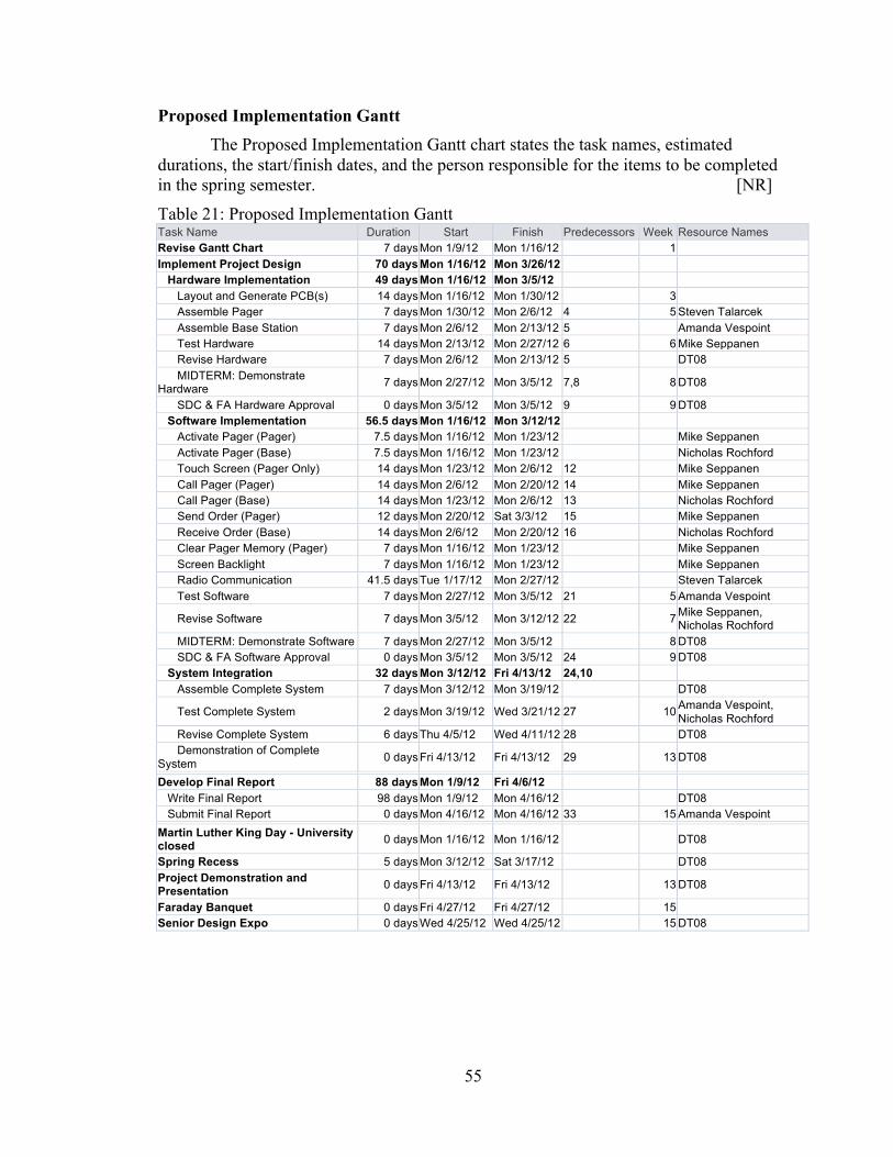
Proposed Implementation Gantt The Proposed Implementation Gantt chart states the task names, estimated
durations, the start/finish dates, and the person responsible for the items to be completed in the spring semester. [NR]
Table 21: Proposed Implementation Gantt Task Name Duration Start Finish Predecessors Week Resource Names Revise Gantt Chart 7 days Mon 1/9/12 Mon 1/16/12 1 Implement Project Design 70 days Mon 1/16/12 Mon 3/26/12 Hardware Implementation 49 days Mon 1/16/12 Mon 3/5/12 Layout and Generate PCB(s) 14 days Mon 1/16/12 Mon 1/30/12 3 Assemble Pager 7 days Mon 1/30/12 Mon 2/6/12 4 5 Steven Talarcek Assemble Base Station 7 days Mon 2/6/12 Mon 2/13/12 5 Amanda Vespoint Test Hardware 14 days Mon 2/13/12 Mon 2/27/12 6 6 Mike Seppanen Revise Hardware 7 days Mon 2/6/12 Mon 2/13/12 5 DT08 MIDTERM: Demonstrate Hardware 7 days Mon 2/27/12 Mon 3/5/12 7,8 8 DT08
SDC & FA Hardware Approval 0 days Mon 3/5/12 Mon 3/5/12 9 9 DT08 Software Implementation 56.5 days Mon 1/16/12 Mon 3/12/12 Activate Pager (Pager) 7.5 days Mon 1/16/12 Mon 1/23/12 Mike Seppanen Activate Pager (Base) 7.5 days Mon 1/16/12 Mon 1/23/12 Nicholas Rochford Touch Screen (Pager Only) 14 days Mon 1/23/12 Mon 2/6/12 12 Mike Seppanen Call Pager (Pager) 14 days Mon 2/6/12 Mon 2/20/12 14 Mike Seppanen Call Pager (Base) 14 days Mon 1/23/12 Mon 2/6/12 13 Nicholas Rochford Send Order (Pager) 12 days Mon 2/20/12 Sat 3/3/12 15 Mike Seppanen Receive Order (Base) 14 days Mon 2/6/12 Mon 2/20/12 16 Nicholas Rochford Clear Pager Memory (Pager) 7 days Mon 1/16/12 Mon 1/23/12 Mike Seppanen Screen Backlight 7 days Mon 1/16/12 Mon 1/23/12 Mike Seppanen Radio Communication 41.5 days Tue 1/17/12 Mon 2/27/12 Steven Talarcek Test Software 7 days Mon 2/27/12 Mon 3/5/12 21 5 Amanda Vespoint
Revise Software 7 days Mon 3/5/12 Mon 3/12/12 22 7 Mike Seppanen, Nicholas Rochford
MIDTERM: Demonstrate Software 7 days Mon 2/27/12 Mon 3/5/12 8 DT08 SDC & FA Software Approval 0 days Mon 3/5/12 Mon 3/5/12 24 9 DT08 System Integration 32 days Mon 3/12/12 Fri 4/13/12 24,10 Assemble Complete System 7 days Mon 3/12/12 Mon 3/19/12 DT08
Test Complete System 2 days Mon 3/19/12 Wed 3/21/12 27 10 Amanda Vespoint, Nicholas Rochford
Revise Complete System 6 days Thu 4/5/12 Wed 4/11/12 28 DT08 Demonstration of Complete System 0 days Fri 4/13/12 Fri 4/13/12 29 13 DT08
Develop Final Report 88 days Mon 1/9/12 Fri 4/6/12 Write Final Report 98 days Mon 1/9/12 Mon 4/16/12 DT08 Submit Final Report 0 days Mon 4/16/12 Mon 4/16/12 33 15 Amanda Vespoint Martin Luther King Day - University closed 0 days Mon 1/16/12 Mon 1/16/12 DT08
Spring Recess 5 days Mon 3/12/12 Sat 3/17/12 DT08 Project Demonstration and Presentation 0 days Fri 4/13/12 Fri 4/13/12 13 DT08
Faraday Banquet 0 days Fri 4/27/12 Fri 4/27/12 15 Senior Design Expo 0 days Wed 4/25/12 Wed 4/25/12 15 DT08
56
6. Design Team Information Nicholas Rochford, Electrical Engineering, Project Leader Michael Seppanen, Electrical Engineering, Software Manager Steven Talarcek, Electrical Engineering & Applied Mathematics, Hardware Manager Amanda Vespoint, Electrical Engineering, Archivist 7. Conclusion The Advanced Restaurant Paging System provides realistic requirements that will meet specific needs to surpass current limitations in the restaurant industry. The block diagrams as well as the functional requirements provide an overview of the process that is to be implemented. The sequence diagrams assist in the development of how the overall pager will be interpreted by a user. It is important to understand how the user will interact with this device when picking parts and arranging sequences. All of the parts chosen and the software design contributed in meeting the design requirements. This paging system and the base station will work collectively to meet the original requirements. [AV]
8. References 1.) (n.d.). Retrieved March 2011, from Long Range Systems:
http://www.pager.net/Long-Range-Systems/Restaurant-Pagers.html 2.) Livingston, J., Blink, R. P., & Lovegreen, K. J. (2004). Patent No. 6,783,066.
United States. 3.) Quatro, C. (2007). Patent No. US 2007/0040652. United States.
Wireless Paging Systems. (n.d.). Retrieved March 2011, from HME Wireless: http://www.hmewireless.com/
4.) Ida, Nathan. Engineering Electromagnetics. New York, New York: Springer-Verlag, 2004. Book
57
9. Appendix: Data Sheets
• Main PIC: PIC24FJ256DA210 http://ww1.microchip.com/downloads/en/DeviceDoc/39969b.pdf
• Secondary PIC: PIC24FJ16GA002 http://ww1.microchip.com/downloads/en/DeviceDoc/39881D.pdf
• Newhaven 4.3” Touchscreen: NHD-4.3-480272MF-ATXI#-T-1 http://www.newhavendisplay.com/specs/NHD-4.3-480272MF-ATXI-T-1.pdf
• 512kB SRAM: IS61WV25616BLL-10TL http://www.issi.com/pdf/61WV25616.pdf
• Accelerometer: MMA8453QR1 http://cache.freescale.com/files/sensors/doc/data_sheet/MMA8453Q.pdf
• Wireless radio: MRF24J40MA http://ww1.microchip.com/downloads/en/DeviceDoc/70329b.pdf
• 8MB Flash: SST25VF064C-80-4I-SCE-ND http://ww1.microchip.com/downloads/en/DeviceDoc/25036A.pdf
• Vibrator Motor Drive: MAX1749 http://datasheets.maxim-ic.com/en/ds/MAX1749.pdf
• Buck Chip: SP6650EU-L http://www.exar.com/Common/Content/Document.ashx?id=707
• Boost Chip: LT1303CS8#PBF http://cds.linear.com/docs/Datasheet/lt1303.pdf
• Battery Fuel Gauge: LTC2942CDCB#TRMPBF http://cds.linear.com/docs/Datasheet/2942fa.pdf
• LiPo Battery Charger: MCP73871-2CCI/ML http://ww1.microchip.com/downloads/en/DeviceDoc/22090a.pdf
• Ethernet: ENC28J60 http://ww1.microchip.com/downloads/en/DeviceDoc/39662c.pdf
• Keypad: 96BB2-056-F http://media.digikey.com/pdf/Data%20Sheets/Grayhill%20PDFs/96%20Series.pdf
Related Documents