7 Advanced Mechanical Vapor-Compression Desalination System Jorge R. Lara, Omorinsola Osunsan and Mark T. Holtzapple Texas A&M University United States 1. Introduction Vapor compression is a reliable and robust desalination technology that is attractive because of its capacity to treat large volumes of water with a wide range of salt concentrations. However, compared to other major desalination technologies such as reverse osmosis, mechanical vapor compression has had relatively high operating and capital costs. New innovative developments in compressor and evaporator designs make it possible to reduce energy consumption so it is a more competitive alternative. Texas A&M University has developed an advanced vapor-compression desalination system that operates at high temperatures. Advanced sheet-shell latent heat exchangers promote dropwise condensation allowing small temperature and pressure differentials between the saturated boiling liquid and the condensing steam, hence reducing the energy requirements. This newer system consists of a train of non-scaling evaporators arranged so feed water flows countercurrently, recovering heat from both the condensate stream and the concentrated discharge brine. A high-efficiency gerotor compressor provides the compression work required to return saturated steam to the initial stage of the evaporator train. An experimental investigation of hydrophobic copper plates described below shows that extraordinarily high heat transfer coefficients can be attained. The gerotor compressor is particularly advantageous for applications where either electricity or mechanical energy is available. Extensive studies in dropwise condensation show that for low temperature differentials across the hydrophobic plate, heat transfer coefficients will increase with elevated steam pressures. According to the data described in this study, dropwise condensation of saturated steam and forced-convection boiling of saturated water separated by a thin hydrophobic copper plate result in ultra-efficient heat transfer. The forced convection in the water chamber is produced by a liquid jet ejector. 1.1 Advanced mechanical vapor-compression desalination system Figure 1 shows the advanced mechanical vapor-compression desalination system. In this example, three evaporator stages are illustrated, but fewer or more could be employed (Holtzapple et al., 2010). The left-most evaporator is at the lowest pressure and the right- most evaporator is at the highest pressure. In the left-most evaporator, the vapor space above the boiling water is connected to the compressor inlet. The work added to the compressor causes the discharged steam to be superheated. The superheat is removed in the desuperheater. www.intechopen.com

Welcome message from author
This document is posted to help you gain knowledge. Please leave a comment to let me know what you think about it! Share it to your friends and learn new things together.
Transcript
7
Advanced Mechanical Vapor-Compression Desalination System
Jorge R. Lara, Omorinsola Osunsan and Mark T. Holtzapple Texas A&M University
United States
1. Introduction
Vapor compression is a reliable and robust desalination technology that is attractive because of its capacity to treat large volumes of water with a wide range of salt concentrations. However, compared to other major desalination technologies such as reverse osmosis, mechanical vapor compression has had relatively high operating and capital costs. New innovative developments in compressor and evaporator designs make it possible to reduce energy consumption so it is a more competitive alternative. Texas A&M University has developed an advanced vapor-compression desalination system that operates at high temperatures. Advanced sheet-shell latent heat exchangers promote dropwise condensation allowing small temperature and pressure differentials between the saturated boiling liquid and the condensing steam, hence reducing the energy requirements. This newer system consists of a train of non-scaling evaporators arranged so feed water flows countercurrently, recovering heat from both the condensate stream and the concentrated discharge brine. A high-efficiency gerotor compressor provides the compression work required to return saturated steam to the initial stage of the evaporator train. An experimental investigation of hydrophobic copper plates described below shows that extraordinarily high heat transfer coefficients can be attained. The gerotor compressor is particularly advantageous for applications where either electricity or mechanical energy is available. Extensive studies in dropwise condensation show that for low temperature differentials across the hydrophobic plate, heat transfer coefficients will increase with elevated steam pressures. According to the data described in this study, dropwise condensation of saturated steam and forced-convection boiling of saturated water separated by a thin hydrophobic copper plate result in ultra-efficient heat transfer. The forced convection in the water chamber is produced by a liquid jet ejector.
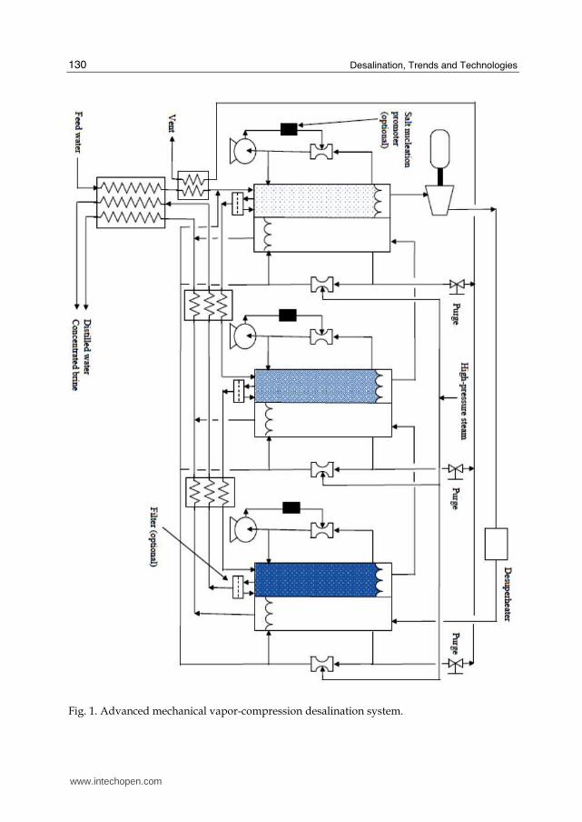
1.1 Advanced mechanical vapor-compression desalination system Figure 1 shows the advanced mechanical vapor-compression desalination system. In this example, three evaporator stages are illustrated, but fewer or more could be employed (Holtzapple et al., 2010). The left-most evaporator is at the lowest pressure and the right-most evaporator is at the highest pressure. In the left-most evaporator, the vapor space above the boiling water is connected to the compressor inlet. The work added to the compressor causes the discharged steam to be superheated. The superheat is removed in the desuperheater.
www.intechopen.com
Desalination, Trends and Technologies
130
Fig. 1. Advanced mechanical vapor-compression desalination system.
www.intechopen.com
Advanced Mechanical Vapor-Compression Desalination System
131
The saturated high-pressure steam that exits the desuperheater enters the condensing side of the right-most evaporator. As this steam condenses, it evaporates water from the boiling side thereby producing steam that can be fed to the middle evaporator. In the middle evaporator, the steam condenses, which causes more steam to be produced on the boiling-water side. This steam then enters the left-most evaporator where it condenses and evaporates water from boiling side. The water evaporated from the boiling side enters the compressor, as previously described. The evaporators are operated at elevated temperature and pressure, which accomplishes the following: (a) the physical size of the compressor is reduced, thereby reducing its cost and (b) in the evaporators, high heat transfer coefficients are obtained. The primary disadvantage of operating at elevated temperature is that it promotes scaling on heat exchanger surfaces, primarily from salts with “reverse solubility,” i.e., those salts in which the solubility decreases at elevated temperature. Examples of reverse solubility salts are calcium carbonate, magnesium carbonate, calcium sulfate, and magnesium sulfate. Commonly, to limit scaling, the maximum heat exchanger temperature is ~120oC; however, at this temperature and pressure, the compressor is physically large and heat transfer coefficients are poor. It is highly desirable to increase the operating temperature, which requires methods to address scale formation such as the following: (a) remove carbonates from the feed water by acidification and stripping the resulting carbon dioxide; (b) remove sulfates via ion exchange; (c) promote salt nucleation in the bulk fluid rather than on surfaces; (d) abrade heat exchanger surfaces with circulating “cleaning balls” commonly made from rubber; and (e) apply non-stick coatings to heat exchanger surfaces. In the evaporators, the steam-side heat transfer coefficient improves up to 30% by inducing shearing steam on the condensing surface; the liquid-side heat transfer coefficient improves with forced-convection boiling. This can be accomplished using an internal jet ejector powered by a pump. To preheat the feed to the evaporators, a sensible heat exchanger is employed, which exchanges thermal energy between the incoming feed water and the discharged distilled water and concentrated brine. As shown in Figure 1, the preheated feed water is fed to the left-most evaporator. In a countercurrent series manner, the brine exiting the left-most evaporator is directed to the middle evaporator and the brine exiting the middle evaporator is directed to the right-most evaporator. As the brine flows from left to right, it becomes ever more concentrated. In the left-most evaporator (lowest brine concentration), the pressure ratio between the condensing steam and boiling water is minimal. In the right-most evaporator (highest brine concentration), the pressure ratio between the condensing steam and boiling water is maximal. Because noncondensable gases are present in the feed water, it will be necessary to purge them from the system. The purged gases exit with steam, which is sent to a heat exchanger that preheats the incoming feed to the left-most evaporator.
1.2 Mass and energy balance The steam-side energy balance (Lara, 2005) is
q = ms(Hs – Hc) = mshfg (1)
where
q = rate of heat transfer (W)
www.intechopen.com
Desalination, Trends and Technologies
132
ms = rate of steam flow (kg/s) Hc = specific enthalpy of condensate (J/kg) Hs = specific enthalpy of steam (J/kg) hfg = latent heat of evaporation (J/kg) The saltwater-side energy balance is:
q = mv Hv – mf Hf + mb Hb
= (mf – mb) Hv – mf Hf + mb Hb (2)
where mf = rate of saltwater feed flow (kg/s) mb = rate of exiting brine flow (kg/s) mv = mf – mb = rate of vapor flow to the next effect (kg/s) Hv = specific enthalpy of vapor going to the next effect (J/kg) Hf = specific enthalpy of saltwater feed (J/kg) Hb = specific enthalpy of exiting brine (J/kg)
Using the boiling temperature as a reference, the enthalpy Hf can be calculated from the specific heat of saltwater Cpf (J/(kgּ°C))
Hf = Cpf (Tb – Tf) (3)
where Tb = temperature of brine exiting latent heat exchanger (°C) Tf = temperature of saltwater entering latent heat exchanger (°C)
At steady-state flow conditions in the evaporator, for seawater feed, the saltwater concentration in the right-most evaporator has been set to 7%. Under these circumstances, there is an appreciable boiling point elevation. The vapor leaving the evaporator solution is superheated by about 1.5 °C, which corresponds to the boiling point elevation. Using the boiling temperature as a reference (i.e., Hb = 0), the specific enthalpy Hv of the leaving vapor equals the latent heat of vaporization plus the sensible superheat. However, the sensible superheat is small so it is approximately true that Hv is the latent heat of vaporization, which is hfg. With this simplifying assumption, the steady-state evaporator energy balance derived using Equations 1 to 3 becomes:
ms hfg = (mf – mb) hfg – mf Cpf (Tb – Tf) + 0 (4)
1.3 Pressure drop in the heat exchanger For two-phase flow inside horizontal tubes and channels (ASHRAE Fundamentals Handbook, 2001), the pressure gradient is the sum of frictional and momentum terms
friction momentum
dP dP dP
dz dz dz+⎛ ⎞ ⎛ ⎞= ⎜ ⎟ ⎜ ⎟⎝ ⎠ ⎝ ⎠ (5)
Detailed analysis of the pressure drop in the hydrophobic heat exchanger was performed by Lara (2005), and it was concluded that pressure drop in the sheet-shell heat exchanger is not a major issue. As described below, the advanced mechanical vapor-compression desalination system has two key components: (1) hydrophobic heat exchanger, and (2) high-efficiency compressor.
www.intechopen.com
Advanced Mechanical Vapor-Compression Desalination System
133
2. Hydrophobic heat exchanger
An extensive experimental investigation on hydrophobic heat exchangers was performed (Lara & Holtzapple, 2010). The study shows dropwise condensation on the condensing surface and forced-convective boiling on the boiling surface make a very efficient heat transfer mechanism that delivers heat transfer coefficients of the order of 277 kW/(m2 ּ°C) for 0.2-mm-thick vertical copper plates coated with 2.54-µm-thick hydrophobic Ni-P-PTFE coating for steam at 827 kPa. The extraordinarily high heat transfer coefficient requires small pressure differentials between the condensing and the boiling chambers, hence the compression energy requirement of the system is small. Hydrophobic heat exchangers perform best at high pressure (Rose, 2002); therefore, the compressor must operate at high pressures and small compression ratios. The mechanical vapor-compression system described in this study uses an innovative gerotor compressor, which is now commercially available from StarRotor Corporation (Murphey et al., 2010). During the experimental investigation, heat transfer coefficients were measured in vertical heat exchangers. Two different square, thin-sheet plate designs were tested. One had round-dimpled spacers, and the other had round-shaped vertical-grooved spacers. In both cases, the experimental plates were mounted in a sealed two-chamber apparatus with condensing saturated steam on one side and boiling liquid water on the other (Figure 2). The liquid-side heat transfer mechanism employed either natural or forced convection pool boiling of saturated water. The steam-side heat transfer mechanism was condensing saturated steam with either filmwise or dropwise condensation.
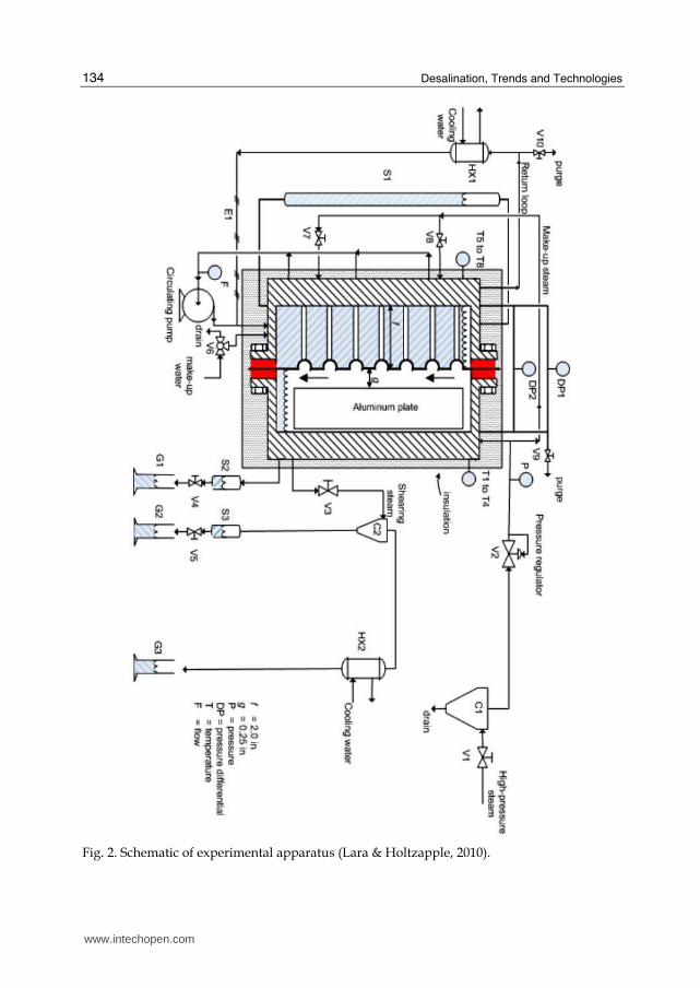
2.1 Apparatus and procedure The experimental apparatus is tailored to observe and manipulate key heat transfer variables. The apparatus (Figure 2) consists of two sections: (1) a boiling water chamber and (2) a condensing steam chamber. Both chambers are made of stainless steel 304 and are divided by the test plate. The whole assembly is bolted together. To prevent leakage, a gasket is placed between each side of the test plate and frame. Data were collected only after steady state was achieved. High-pressure steam enters valve V1 into cyclone C1 where liquid is separated, thus ensuring the steam quality entering the apparatus is 1.0. Pressure regulator V2 sets the condenser pressure, which is measured by pressure gauge P. The steam enters the condenser, which has a 3.2-mm gap that is set by the thickness of the aluminum plate inserted into the condenser. At the bottom of the condenser, condensate flows into sight glass S2. By manually opening valve V4, the liquid level in sight glass S2 can be maintained constant. The drained liquid is collected in graduated cylinder G1 and is measured over a 90-s interval. (Note: This manual method of collecting condensate was more reproducible than steam traps.) The rate of shearing steam flowing past the plate is regulated by valve V3. Cyclone C2 separates liquid entrained with the shearing steam. The collected liquid enters sight glass S3; by manually opening valve V5, the liquid level in sight glass S3 is kept constant. The drained liquid collected in graduated cylinder G2 is measured over a 90-s interval. The steam exiting cyclone C2 enters heat exchanger HX2 where it condenses and is collected in graduated cylinder G3 over a 90-s interval. The amount of liquid collected in graduated cylinder G3 is compared to the amount of liquid collected in both graduated cylinders G1 and G2 so that the ratio R of each flow can be measured. Knowing the gap g (3.2 mm), the plate depth, and the steam density allows the velocity of the shearing steam v to be measured.
www.intechopen.com
Desalination, Trends and Technologies
134
Fig. 2. Schematic of experimental apparatus (Lara & Holtzapple, 2010).
www.intechopen.com
Advanced Mechanical Vapor-Compression Desalination System
135
The boiling side is flooded with tap water; sight glass S1 ensures the liquid level is kept constant. If necessary, excess liquid can be drained or make up water added by manually opening three-way valve V6. The steam evaporated from the boiler enters heat exchanger HX1 where it condenses. The condensate is heated to saturation using electric resistance heater E1. If necessary, make-up steam can be added to the boiler by opening valves V7 and V8. To induce forced convection in the boiler, a pump circulates the liquid. An all-metal flow meter measures the rate of circulating liquid. Knowing the gap f and the plate dimensions, the liquid velocity can be calculated. To ensure that noncondensable gases are removed from the system, valves V9 and V10 allow a small stream to be purged to the atmosphere. The temperature differential ΔT between the steam side and the liquid side is set by the amount of cooling water flowing through the heat exchanger HX1, the amount of make-up steam added through valves V7 and V8, and the heat added through resistance heater E1. The differential pressure between the two chambers is measured using differential pressure gauges DP1 and DP2. One operates from 0 to 2 psid (0 to 13,800 Pa) and the other operates from 0 to 10 psid (0 to 69,000 Pa). The measured pressure differential ΔP between chambers and the steam pressure P allows ΔT to be determined using steam tables. Four thermocouples measure the temperatures in each quadrant of the condenser. Similarly, four thermocouples T5 to T8 measure the temperatures in each quadrant of the boiler. Because thermocouples are not particularly accurate, they were not used to measure ΔT across the test plate. Instead, their purpose was to ensure uniform temperatures in each quadrant of the boiler and of the condenser. Using steam tables, the thermocouple readings were found to be consistent with the readings taken by the pressure gauge P and differential pressure gauges DP1 and DP2. Thermal losses from insulation are calculated by opening valves V7 and V8, which equalizes the pressures in both chambers with saturated steam so there is no temperature difference across the plate. The condensate is collected and used to determine the heat loss through the steam-side insulation. This collected steady-state condensate serves as the baseline, which is subtracted from the condensate collected in both graduated cylinders G1 and G2 during the experiments; the net condensate collected (m) is substituted in Equation 8 to calculate heat flux. This allows the heat transfer through the plate to be measured without interference from heat loss through the insulation. Three different plate materials were tested: (1) 0.762-mm-thick naval brass 464 (2) 0.2-mm-thick copper, and (3) 0.127-mm-thick titanium grade 2.
2.2 Calculation of heat transfer coefficient Neglecting fouling, the theoretical overall heat transfer coefficient can be calculated using
1
1 1
cond boiling
Ux
h h k
= ⎛ ⎞+ + ⎜ ⎟⎝ ⎠ (6)
where U = overall heat transfer coefficient (kW/(m2ּ°C)) x = plate thickness (m) k = thermal conductivity (kW/(mּ°C)) hcond = condensation heat transfer coefficient (kW/(m2ּ°C)) hboiling= boiling heat transfer coefficient (kW/(m2ּ°C))
www.intechopen.com
Desalination, Trends and Technologies
136
Measured heat transfer coefficients U are obtained from
q
UT
⎛ ⎞⎜ ⎟= ⎜ ⎟Δ⎝ ⎠ (7)
and
q = (mhfg)/A (8)
where q = heat flux (kW/m2) m = net condensate collected from the apparatus (kg/s) hfg = latent heat of condensation (kJ/kg) A = effective heat transfer area (m2) ΔT = temperature differential across the plate (°C)
Dropwise condensation performs best at higher pressures and small temperature differentials across the plate (Rose, 2002). Moreover, high operating pressures increase steam density which allows mechanical vapor-compression (MVC) desalination systems to use smaller compressors.
2.3 Heat transfer enhancement techniques Active and passive heat transfer enhancement techniques for heat exchangers have been investigated intensively (Bergles, 2002). Fourth-generation heat transfer technology involves simultaneous application of several techniques to produce an enhancement larger than the individual techniques operating separately. Dropwise condensation has been studied for the past 60 years (Rose, 2002). Experiments with brass tubes show dropwise condensation has heat transfer coefficients 1.6–28.6 times greater than filmwise condensation (Ma et al., 2002). The experiments reported herein enhanced heat transfer by simultaneously employing the following: (1) passive electroless Ni-P-PTFE thin-hydrophobic coating to promote dropwise condensation on the steam side and to inhibit fouling in the boiling side, (2) active forced convection circulating saturated liquid in the boiling chamber, and (3) active shearing steam on the condensing surface. This study measures the heat transfer with forced-convective boiling (liquid side) and dropwise condensation (steam side). The following factors were investigated: (a) saturated steam temperature; (b) temperature differential ΔT across the plate; (c) shearing steam; (d) shearing liquid.
2.4 Summary of experimental results The first plate was round-dimpled 0.762-mm-thick naval brass (k = 116 W/(mּ°C)), which was roughened via sand-blasting on the liquid side to promote nucleation. The condensing metal surface was either bare (filmwise condensation) or coated with 0.635-µm-thick layer of Ni-P-PTFE (dropwise condensation). Shearing steam on the condensing surface enhanced the overall heat transfer coefficient by 1.6 times and forced liquid convection increased it by additional 1.4 times. Interestingly, excessive shearing steam reduced the overall heat transfer coefficient. Presumably, this occurred because a film formed that increased the thermal resistance across the plate and disrupted the dropwise condensation mode. Without coating, the best operating point delivered U = 16.5 kW/(m2·°C) (saturated steam T = 166 °C, P = 722 kPa, ΔT = 0.2 °C). With 0.635-µm Ni-P-PTFE
www.intechopen.com
Advanced Mechanical Vapor-Compression Desalination System
137
hydrophobic coating, the best operating point delivered an overall heat transfer coefficient U = 99.4 kW/(m2·°C) (saturated steam T = 166 °C, P = 722 kPa, ΔT = 0.2 °C, shearing steam v = 0.16 m/s, R ≈ 1 kg shearing steam/kg condensate, saturated liquid side v = 1.57 m/s). The second plate was round-dimpled 0.2-mm-thick copper (k = 400 W/(mּ°C)). The plate surfaces in both chambers were modified with 0.635-µm Ni-P-PTFE hydrophobic layer. Experiments on this plate were performed under two different conditions in the saturated liquid chamber: (1) forced convection and (2) forced convection with PTFE boiling stones as a dynamic nucleation agent. For the first condition, the best operating point delivered an overall heat transfer coefficient U = 159 kW/(m2·°C) (saturated steam T = 166 °C, P = 722 kPa, ΔT = 0.2 °C, shearing steam v = 0.4 m/s, R ≈ 1 kg shearing steam/kg condensate, saturated liquid side v = 1.57 ft/s). For the second condition, the best operating point delivered an overall heat transfer coefficient U = 182 kW/(m2·°C) (saturated steam T = 166 °C, P = 722 kPa, ΔT = 0.2 °C, steam velocity v = 0.49 m/s, R ≈ 1 kg shearing steam/kg condensate, saturated liquid velocity v = 1.57 m/s). The third round-dimpled plate was made of grade-2 bare 0.12-mm-thick titanium (k = 21.9 W/(mּ°C)). The best design point delivered U = 77.8 kW/(m2ּ°C) (saturated steam T = 166 °C, P = 722 kPa, ΔT = 0.2 °C, steam velocity v = 0.15 m/s, R = 1.5 kg shearing steam/kg, saturated liquid velocity v = 1.57 m/s). The fourth plate was vertical-grooved 0.2-mm-thick copper (k = 400 W/(mּ°C)) coated with 0.635-µm Ni-P-PTFE hydrophobic coating. The best design point delivered U = 192 kW/(m2ּ°C) (saturated steam T = 166 °C, P = 722 kPa, ΔT = 0.2 °C, steam velocity v = 0.16 m/s, R ≈ 0.43 kg shearing steam/kg condensate, saturated liquid velocity v = 1.57 m/s). The last experiment was performed on the copper plate previously described but with a modified chemistry for the coating. Lead-free 2.5-µm-thick hydrophobic Ni-P-PTFE delivered 21% better heat transfer coefficient. For this case, the best design point was U = 240 kW/(m2ּ°C) (saturated steam T = 166°C, P = 722 kPa, ΔT = 0.2 °C, steam velocity v = 0.23 m/s, R ≈ 0.6 kg shearing steam/kg condensate, saturated liquid velocity v = 1.57 m/s).
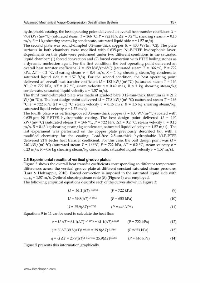
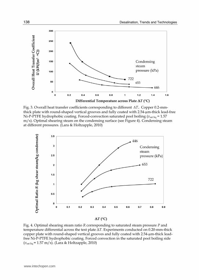
2.5 Experimental results of vertical groove plates Figure 3 shows the overall heat transfer coefficients corresponding to different temperature differences across the vertical groove plate at different constant saturated steam pressures (Lara & Holtzapple, 2010). Forced convection is imposed in the saturated liquid side with vsat liq = 1.57 m/s. Optimal shearing steam ratio (R) (Figure 4) was employed. The following empirical equations describe each of the curves shown in Figure 3:
U = 61.1(ΔT)–0.9153 (P = 722 kPa) (9)
U = 39.8(ΔT)–0.8214 (P = 653 kPa) (10)
U = 25.9(ΔT)–0.7715 (P = 446 kPa) (11)
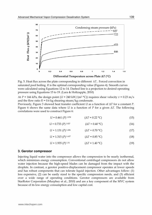
Equations 9 to 11 can be used to calculate the heat flux:
q = U ΔT = 61.1(ΔT)1–0.9153 = 61.1(ΔT) 0.0847 (P = 722 kPa) (12)
q = U ΔT 39.8(ΔT)1–0.8214 = 39.8(ΔT) 0.1786 (P =653 kPa) (13)
q = U ΔT = 25.9(ΔT)1–0.7715= 25.9(ΔT)0.2285 (P = 446 kPa) (14)
Figure 5 presents this information graphically.
www.intechopen.com
Desalination, Trends and Technologies
138
Fig. 3. Overall heat transfer coefficients corresponding to different .TΔ Copper 0.2-mm-thick plate with round-shaped vertical grooves and fully coated with 2.54-µm-thick lead-free Ni-P-PTFE hydrophobic coating. Forced-convection saturated pool boiling (vsat liq = 1.57 m/s). Optimal shearing steam on the condensing surface (see Figure 4). Condensing steam at different pressures. (Lara & Holtzapple, 2010)
Fig. 4. Optimal shearing steam ratio R corresponding to saturated steam pressure P and temperature differential across the test plate ΔT. Experiments conducted on 0.20-mm-thick copper plate with round-shaped vertical grooves and fully coated with 2.54-µm-thick lead-free Ni-P-PTFE hydrophobic coating. Forced convection in the saturated pool boiling side (vsat liq = 1.57 m/s). (Lara & Holtzapple, 2010)
www.intechopen.com
Advanced Mechanical Vapor-Compression Desalination System
139
Fig. 5. Heat flux across the plate corresponding to different .TΔ Forced convection in
saturated pool boiling. R is the optimal corresponding value (Figures 4). Smooth curves were calculated using Equations 12 to 14. Dashed line is a projection to desired operating pressure using Equations 15 to 19. (Lara & Holtzapple, 2010)
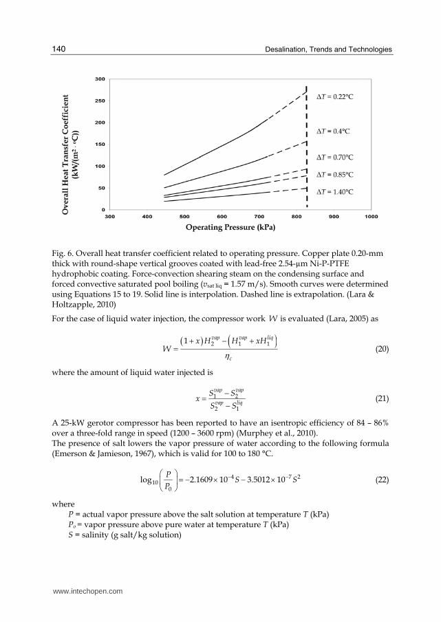
At P = 166 kPa, the design point (U = 240 kW/(m2ּ°C)) requires shear velocity v = 0.23 m/s and the flow ratio R = 0.6 kg shearing steam/kg condensate. Previously, Figure 3 showed heat transfer coefficient U as a function of ΔT for a constant P. Figure 6 shows the same data where U is a function of P for a given ΔT. The following correlations were used to construct Figure 6:
U = 0.461 (P) 1.978 (ΔT = 0.22 °C) (15)
U = 0.733 (P) 1.827 (ΔT = 0.40 °C) (16)
U = 1.131 (P) 1.686 (ΔT = 0.70 °C) (17)
U = 1.315 (P) 1.637 (ΔT = 0.85 °C) (18)
U = 1.935 (P) 1.51 (ΔT = 1.40 °C) (19)
3. Gerotor compressor
Injecting liquid water into the compressor allows the compression to be nearly isothermal, which minimizes energy consumption. Conventional centrifugal compressors do not allow water injection because the high-speed blades can be damaged from the impact with the droplets. In contrast, a gerotor positive-displacement compressor operates at lower speeds and has robust components that can tolerate liquid injection. Other advantages follow: (1) less expensive, (2) can be easily sized to the specific compression needs, and (3) efficient over a wide range of operating conditions. Gerotor compressors are available from StarRotor Corporation (Murphey et al., 2010) and are a key component of the MVC system because of its low energy consumption and low capital cost.
www.intechopen.com
Desalination, Trends and Technologies
140
Fig. 6. Overall heat transfer coefficient related to operating pressure. Copper plate 0.20-mm thick with round-shape vertical grooves coated with lead-free 2.54-µm Ni-P-PTFE hydrophobic coating. Force-convection shearing steam on the condensing surface and forced convective saturated pool boiling (vsat liq = 1.57 m/s). Smooth curves were determined using Equations 15 to 19. Solid line is interpolation. Dashed line is extrapolation. (Lara & Holtzapple, 2010)
For the case of liquid water injection, the compressor work W is evaluated (Lara, 2005) as
( ) ( )2 1 11 vap vap liq
c
x H H xHW η
+ − += (20)
where the amount of liquid water injected is
1 2
2 1
vap vap
vap liq
S Sx
S S
−= − (21)
A 25-kW gerotor compressor has been reported to have an isentropic efficiency of 84 – 86% over a three-fold range in speed (1200 – 3600 rpm) (Murphey et al., 2010). The presence of salt lowers the vapor pressure of water according to the following formula (Emerson & Jamieson, 1967), which is valid for 100 to 180 °C.
4 7 210
0
log 2.1609 10 3.5012 10P
S SP
− −⎛ ⎞ = − × − ×⎜ ⎟⎝ ⎠ (22)
where P = actual vapor pressure above the salt solution at temperature T (kPa) Po = vapor pressure above pure water at temperature T (kPa) S = salinity (g salt/kg solution)
www.intechopen.com
Advanced Mechanical Vapor-Compression Desalination System
141
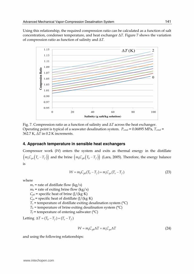
Using this relationship, the required compression ratio can be calculated as a function of salt concentration, condenser temperature, and heat exchanger ΔT. Figure 7 shows the variation of compression ratio as function of salinity and ΔT.
0.95
0.97
0.99
1.01
1.03
1.05
1.07
1.09
1.11
1.13
1.15
0 20 40 60 80 100
Com
pre
ssio
n R
atio
Salinity (g salt/kg solution)
ΔT (K) 2
0
Fig. 7. Compression ratio as a function of salinity and ΔT across the heat exchanger. Operating point is typical of a seawater desalination system. Pcond = 0.06895 MPa, Tcond = 362.7 K, ΔT in 0.2 K increments.
4. Approach temperature in sensible heat exchangers
Compressor work (W) enters the system and exits as thermal energy in the distillate ( )( )s ps s fm C T T− and the brine ( )( )b pb b fm C T T− (Lara, 2005). Therefore, the energy balance
is
( ) ( )b pb b f s ps s fW m C T T m C T T= − + − (23)
where ms = rate of distillate flow (kg/s) mb = rate of exiting brine flow (kg/s) Cpb = specific heat of brine (J/(kg·K) Cps = specific heat of distillate (J/(kg·K) Ts = temperature of distillate exiting desalination system (°C) Tb = temperature of brine exiting desalination system (°C) Tf = temperature of entering saltwater (°C)
Letting ( ) ( )b f s fT T T T TΔ = − = −
b pb s psW m C T m C T= Δ + Δ (24)
and using the following relationships:
www.intechopen.com
Desalination, Trends and Technologies
142
total mass balance: s b fm m m+ =
salt mass balance: f f b bm x m x=
where xb = brine concentration xf = entering saltwater concentration
the following equation is derived:
1
1
1
pb pssb
f
WT C C
mx
x
−⎛ ⎞⎜ ⎟⎜ ⎟ ⎛ ⎞Δ = +⎜ ⎟ ⎜ ⎟⎛ ⎞⎜ ⎟ ⎝ ⎠⎜ − ⎟⎜ ⎟⎜ ⎟⎜ ⎟⎝ ⎠⎝ ⎠ (25)
This TΔ represents the temperature rise of both the exiting distillate and brine. In addition, it is the approach temperature in the sensible heat exchangers.
4. Desalination plant cost analysis
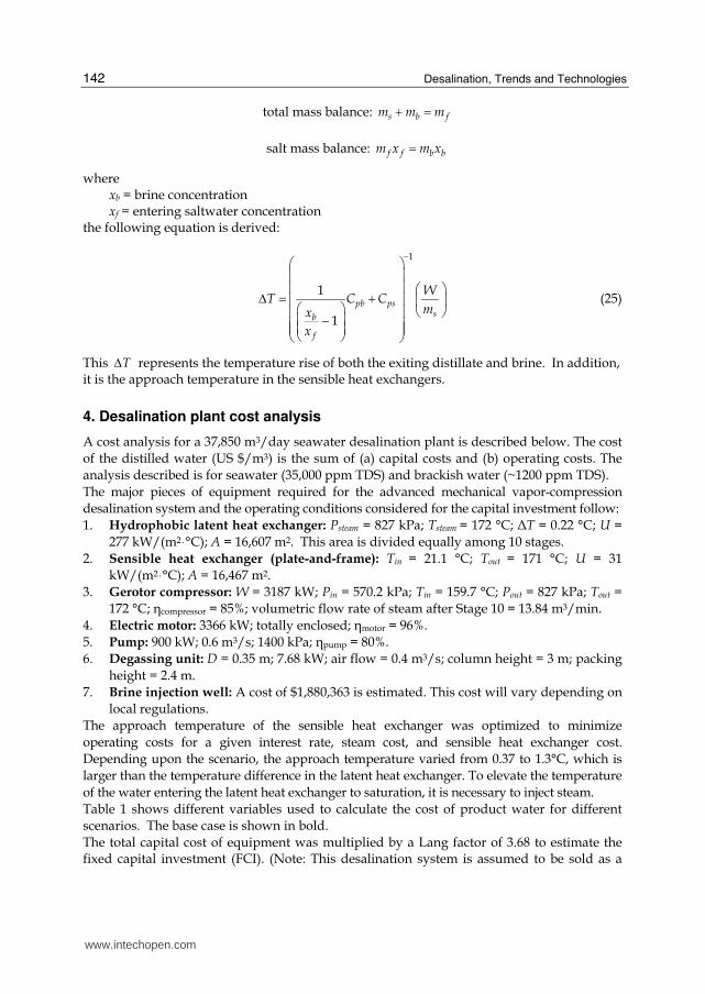
A cost analysis for a 37,850 m3/day seawater desalination plant is described below. The cost of the distilled water (US $/m3) is the sum of (a) capital costs and (b) operating costs. The analysis described is for seawater (35,000 ppm TDS) and brackish water (~1200 ppm TDS). The major pieces of equipment required for the advanced mechanical vapor-compression desalination system and the operating conditions considered for the capital investment follow: 1. Hydrophobic latent heat exchanger: Psteam = 827 kPa; Tsteam = 172 °C; ΔT = 0.22 °C; U =
277 kW/(m2ּ°C); A = 16,607 m2. This area is divided equally among 10 stages. 2. Sensible heat exchanger (plate-and-frame): Tin = 21.1 °C; Tout = 171 °C; U = 31
kW/(m2ּ°C); A = 16,467 m2. 3. Gerotor compressor: W = 3187 kW; Pin = 570.2 kPa; Tin = 159.7 °C; Pout = 827 kPa; Tout =
172 °C; ηcompressor = 85%; volumetric flow rate of steam after Stage 10 = 13.84 m3/min. 4. Electric motor: 3366 kW; totally enclosed; ηmotor = 96%. 5. Pump: 900 kW; 0.6 m3/s; 1400 kPa; ηpump = 80%. 6. Degassing unit: D = 0.35 m; 7.68 kW; air flow = 0.4 m3/s; column height = 3 m; packing
height = 2.4 m. 7. Brine injection well: A cost of $1,880,363 is estimated. This cost will vary depending on
local regulations. The approach temperature of the sensible heat exchanger was optimized to minimize operating costs for a given interest rate, steam cost, and sensible heat exchanger cost. Depending upon the scenario, the approach temperature varied from 0.37 to 1.3°C, which is larger than the temperature difference in the latent heat exchanger. To elevate the temperature of the water entering the latent heat exchanger to saturation, it is necessary to inject steam. Table 1 shows different variables used to calculate the cost of product water for different scenarios. The base case is shown in bold. The total capital cost of equipment was multiplied by a Lang factor of 3.68 to estimate the fixed capital investment (FCI). (Note: This desalination system is assumed to be sold as a
www.intechopen.com
Advanced Mechanical Vapor-Compression Desalination System
143
packaged unit, which has a lower Lang factor than a field-erected plant.) The capital cost of the purchased equipment for seawater desalination is given in Table 2. The operating cost includes insurance, maintenance, labor, debt service, electricity, and steam. The annual maintenance and insurance costs were assumed to be 4% and 0.5% of the FCI, respectively. Labor cost was assumed to be $500,000/yr. To determine the debt service, the fixed capital investment was amortized using the ordinary annuity equation
( )( )
1 1
1
N
N
iPV R
i
+ −= + (26)
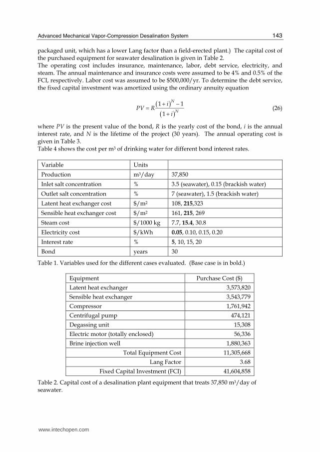
where PV is the present value of the bond, R is the yearly cost of the bond, i is the annual interest rate, and N is the lifetime of the project (30 years). The annual operating cost is given in Table 3. Table 4 shows the cost per m3 of drinking water for different bond interest rates.
Variable Units
Production m3/day 37,850
Inlet salt concentration % 3.5 (seawater), 0.15 (brackish water)
Outlet salt concentration % 7 (seawater), 1.5 (brackish water)
Latent heat exchanger cost $/m2 108, 215,323
Sensible heat exchanger cost $/m2 161, 215, 269
Steam cost $/1000 kg 7.7, 15.4, 30.8
Electricity cost $/kWh 0.05, 0.10, 0.15, 0.20
Interest rate % 5, 10, 15, 20
Bond years 30
Table 1. Variables used for the different cases evaluated. (Base case is in bold.)
Equipment Purchase Cost ($)
Latent heat exchanger 3,573,820
Sensible heat exchanger 3,543,779
Compressor 1,761,942
Centrifugal pump 474,121
Degassing unit 15,308
Electric motor (totally enclosed) 56,336
Brine injection well 1,880,363
Total Equipment Cost 11,305,668
Lang Factor 3.68
Fixed Capital Investment (FCI) 41,604,858
Table 2. Capital cost of a desalination plant equipment that treats 37,850 m3/day of seawater.
www.intechopen.com
Desalination, Trends and Technologies
144
Cost ($/yr) Cost ($/m3)
Electricity ($0.05/kWh) 1,850,550 0.13
Steam ($15.4/1000 kg) 235,177 0.01
Labor 500,000 0.04
Maintenance (0.04 x FCI) 1,664,194 0.12
Insurance (0.005 x FCI) 208,024 0.01
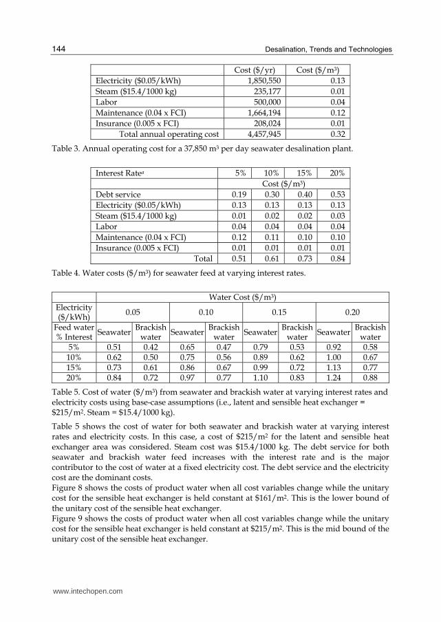
Total annual operating cost 4,457,945 0.32
Table 3. Annual operating cost for a 37,850 m3 per day seawater desalination plant.
Interest Ratea 5% 10% 15% 20%
Cost ($/m3)
Debt service 0.19 0.30 0.40 0.53
Electricity ($0.05/kWh) 0.13 0.13 0.13 0.13
Steam ($15.4/1000 kg) 0.01 0.02 0.02 0.03
Labor 0.04 0.04 0.04 0.04
Maintenance (0.04 x FCI) 0.12 0.11 0.10 0.10
Insurance (0.005 x FCI) 0.01 0.01 0.01 0.01
Total 0.51 0.61 0.73 0.84
Table 4. Water costs ($/m3) for seawater feed at varying interest rates.
Water Cost ($/m3)
Electricity ($/kWh)
0.05 0.10 0.15 0.20
Feed water % Interest
SeawaterBrackish
water Seawater
Brackish water
SeawaterBrackish
water Seawater
Brackish water
5% 0.51 0.42 0.65 0.47 0.79 0.53 0.92 0.58 10% 0.62 0.50 0.75 0.56 0.89 0.62 1.00 0.67 15% 0.73 0.61 0.86 0.67 0.99 0.72 1.13 0.77 20% 0.84 0.72 0.97 0.77 1.10 0.83 1.24 0.88
Table 5. Cost of water ($/m3) from seawater and brackish water at varying interest rates and electricity costs using base-case assumptions (i.e., latent and sensible heat exchanger = $215/m2. Steam = $15.4/1000 kg).
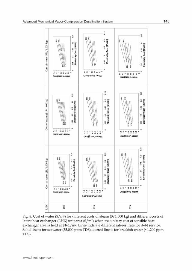
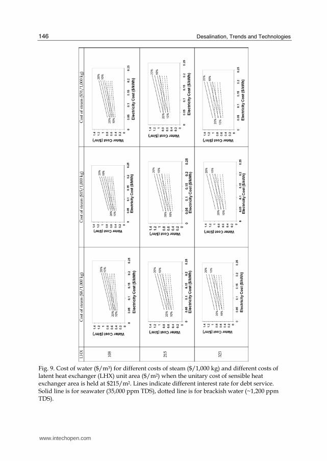
Table 5 shows the cost of water for both seawater and brackish water at varying interest rates and electricity costs. In this case, a cost of $215/m2 for the latent and sensible heat exchanger area was considered. Steam cost was $15.4/1000 kg. The debt service for both seawater and brackish water feed increases with the interest rate and is the major contributor to the cost of water at a fixed electricity cost. The debt service and the electricity cost are the dominant costs. Figure 8 shows the costs of product water when all cost variables change while the unitary cost for the sensible heat exchanger is held constant at $161/m2. This is the lower bound of the unitary cost of the sensible heat exchanger. Figure 9 shows the costs of product water when all cost variables change while the unitary cost for the sensible heat exchanger is held constant at $215/m2. This is the mid bound of the unitary cost of the sensible heat exchanger.
www.intechopen.com
Advanced Mechanical Vapor-Compression Desalination System
145
Fig. 8. Cost of water ($/m3) for different costs of steam ($/1,000 kg) and different costs of latent heat exchanger (LHX) unit area ($/m2) when the unitary cost of sensible heat exchanger area is held at $161/m2. Lines indicate different interest rate for debt service. Solid line is for seawater (35,000 ppm TDS), dotted line is for brackish water (~1,200 ppm TDS).
www.intechopen.com
Desalination, Trends and Technologies
146
Fig. 9. Cost of water ($/m3) for different costs of steam ($/1,000 kg) and different costs of latent heat exchanger (LHX) unit area ($/m2) when the unitary cost of sensible heat exchanger area is held at $215/m2. Lines indicate different interest rate for debt service. Solid line is for seawater (35,000 ppm TDS), dotted line is for brackish water (~1,200 ppm TDS).
www.intechopen.com
Advanced Mechanical Vapor-Compression Desalination System
147
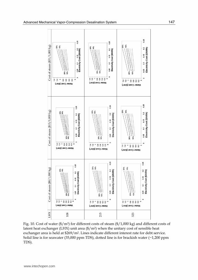
Fig. 10. Cost of water ($/m3) for different costs of steam ($/1,000 kg) and different costs of latent heat exchanger (LHX) unit area ($/m2) when the unitary cost of sensible heat exchanger area is held at $269/m2. Lines indicate different interest rate for debt service. Solid line is for seawater (35,000 ppm TDS), dotted line is for brackish water (~1,200 ppm TDS).
www.intechopen.com
Desalination, Trends and Technologies
148
Figure 10 shows the costs of product water when all cost variables change while the unitary cost for the sensible heat exchanger is held constant at $269/m2. This is the upper bound of the unitary cost of the sensible heat exchanger.
5. Conclusion
Traditionally, mechanical vapor-compression desalination systems are more energy intensive than reverse osmosis and require higher capital and operation costs. The present study describes recent developments in latent heat exchangers and gerotor compressors that make mechanical vapor-compression a competitive alternative to treat high-TDS waters with a robust, reliable, yet economical technology. Using base-case assumptions, fresh water can be produced at $0.51/m3 from seawater and at $0.42/m3 from brackish water (electricity $0.05/kWh, 5% interest, 30-year bond).
6. Legal notice
This desalination technology has been licensed to Terrabon, Inc. The information, estimates, projections, calculations, and assertions expressed in this paper have not been endorsed, approved, or reviewed by any unaffiliated third party, including Terrabon, Inc., and are based on the authors’ own independent research, evaluation, and analysis. The views and opinions of the authors expressed herein do not state or reflect those of such third parties, and shall not be construed as the views and opinions of such third parties.
7. References
American Society of Heating, Refrigerating and Air-Conditioning Engineers, ASHRAE Fundamentals Handbook, Atlanta, GA, 2001.
Bergles, A. E. ExHFT for fourth generation heat transfer technology, Experimental Thermal and Fluid Science, 26 (2002) 335-344.
Emerson, W. H. and Jamieson, D. T. Some physical properties of seawater in various concentrations, Desalination, 3 (1967) 213.
Holtzapple, M. T., Lara, J. R. Watanawanavet, S. Heat exchanger system for desalination. Patent Disclosure. Texas A&M University, College Station Texas 77843, Sept 2010.
Lara, J. R., An Advanced Vapor-Compression Desalination System. PhD. Dissertation., Texas A&M University. Dec 2005.
Lara, J. R., Holtzapple, M. T. Experimental Investigation of Dropwise Condensation on Hydrophobic Heat Exchangers. Department of Chemical Engineering Texas A&M University, 3122 TAMU, College Station, TX 77843-3122, February 2010.
Lara, J. R., Noyes, G., Holtzapple M. T. An investigation of high operating temperatures in mechanical vapor-compression desalination, Desalination, 227 (2008) 217-232.
Ma, X., Chen, D., Xu, J., Lin, C., Ren, Z. Long, Influence of processing conditions of polymer film on dropwise condensation heat transfer, International Journal of Heat and Mass Transfer, 45 (2002) 3405–3411.
Murphey, M., Rabroker, A., Holtzapple, M. T. 30-hp Desalination Compressor, Final Report, StarRotor Corporation, 1805 Southwood Dr., College Station, TX 77840.
Rose, J. W. Dropwise condensation theory and experiment: a review, Journal of Power and Energy, 16 (2002) 115-128.
www.intechopen.com

Desalination, Trends and TechnologiesEdited by Michael Schorr
ISBN 978-953-307-311-8Hard cover, 334 pagesPublisher InTechPublished online 28, February, 2011Published in print edition February, 2011
InTech EuropeUniversity Campus STeP Ri Slavka Krautzeka 83/A 51000 Rijeka, Croatia
InTech ChinaUnit 405, Office Block, Hotel Equatorial Shanghai No.65, Yan An Road (West), Shanghai, 200040, China
Phone: +86-21-62489820
The book comprises 14 chapters covering all the issues related to water desalination. These chaptersemphasize the relationship between problems encountered with the use of feed water, the processesdeveloped to address them, the operation of the required plants and solutions actually implemented. Thiscompendium will assist designers, engineers and investigators to select the process and plant configurationthat are most appropriate for the particular feed water to be used, for the geographic region considered, aswell as for the characteristics required of the treated water produced. This survey offers a comprehensive,hierarchical and logical assessment of the entire desalination industry. It starts with the worldwide scarcity ofwater and energy, continues with the thermal - and membrane-based processes and, finally, presents thedesign and operation of large and small desalination plants. As such, it covers all the scientific, technologicaland economical aspects of this critical industry, not disregarding its environmental and social points of view.One of InTech's books has received widespread praise across a number of key publications. Desalination,Trends and Technologies (Ed. Schorr, M. 2011) has been reviewed in Corrosion Engineering, Science &Technology – the official magazine for the Institute of Materials, Minerals & Mining, and Taylor & Francis'sDesalination Publications. Praised for its “multi-faceted content [which] contributes to enrich it,” and describedas “an essential companion...[that] enables the reader to gain a deeper understanding of the desalinationindustry,” this book is testament to the quality improvements we have been striving towards over the lasttwelve months.
How to referenceIn order to correctly reference this scholarly work, feel free to copy and paste the following:
Jorge R. Lara, Omorinsola Osunsan and Mark T. Holtzapple (2011). Advanced Mechanical Vapor-Compression Desalination System, Desalination, Trends and Technologies, Michael Schorr (Ed.), ISBN: 978-953-307-311-8, InTech, Available from: http://www.intechopen.com/books/desalination-trends-and-technologies/advanced-mechanical-vapor-compression-desalination-system
www.intechopen.com
Phone: +385 (51) 770 447 Fax: +385 (51) 686 166www.intechopen.com
Phone: +86-21-62489820 Fax: +86-21-62489821
© 2011 The Author(s). Licensee IntechOpen. This chapter is distributedunder the terms of the Creative Commons Attribution-NonCommercial-ShareAlike-3.0 License, which permits use, distribution and reproduction fornon-commercial purposes, provided the original is properly cited andderivative works building on this content are distributed under the samelicense.
Related Documents


