Advanced Machining Processes

Welcome message from author
This document is posted to help you gain knowledge. Please leave a comment to let me know what you think about it! Share it to your friends and learn new things together.
Transcript

Advanced Machining Processes
Parts Made by Advanced Machining Processes
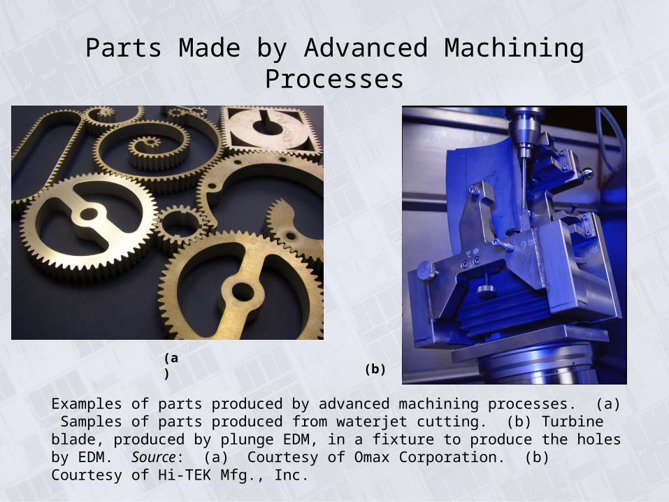
Examples of parts produced by advanced machining processes. (a) Samples of parts produced from waterjet cutting. (b) Turbine blade, produced by plunge EDM, in a fixture to produce the holes by EDM. Source: (a) Courtesy of Omax Corporation. (b) Courtesy of Hi-TEK Mfg., Inc.
(a)(b)
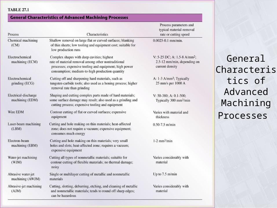
General Characteristics of Advanced MachiningProcesses

Chemical Milling
(a) Missile skin-panel section contoured by chemical milling to improve the stiffness-to-weight ratio of the part. (b) Weight reduction of space-launch vehicles by the chemical milling of aluminum-alloy plates. These panels are chemically milled after the plates first have been formed into shape by a process such as roll forming or stretch forming. The design of the chemically machined rib patterns can be modified readily at minimal cost.

Chemical-Machining
(a) Schematic illustration of the chemical-machining process. Note that no forces or machine tools are involved in this process. (b) Stages in producing a profiled cavity by chemical machining; note the undercut.

Surface Roughness
and Tolerances
in Machining
Surface roughness and tolerances obtained in various machining processes. Note the wide range within each process (see also Fig. 23.13). Source: Machining Data Handbook, 3rd ed. Copyright © 1980. Used by permission of Metcut Research Associates, Inc.

Parts Made by Chemical Blanking
Various parts made by chemical blanking. Note the fine detail. Source: Courtesy of Buckbee-Mears, St. Paul.

Electrochemical Machining
Schematic illustration of the electrochemical machining process.
Parts Made by Electrochemical Machining
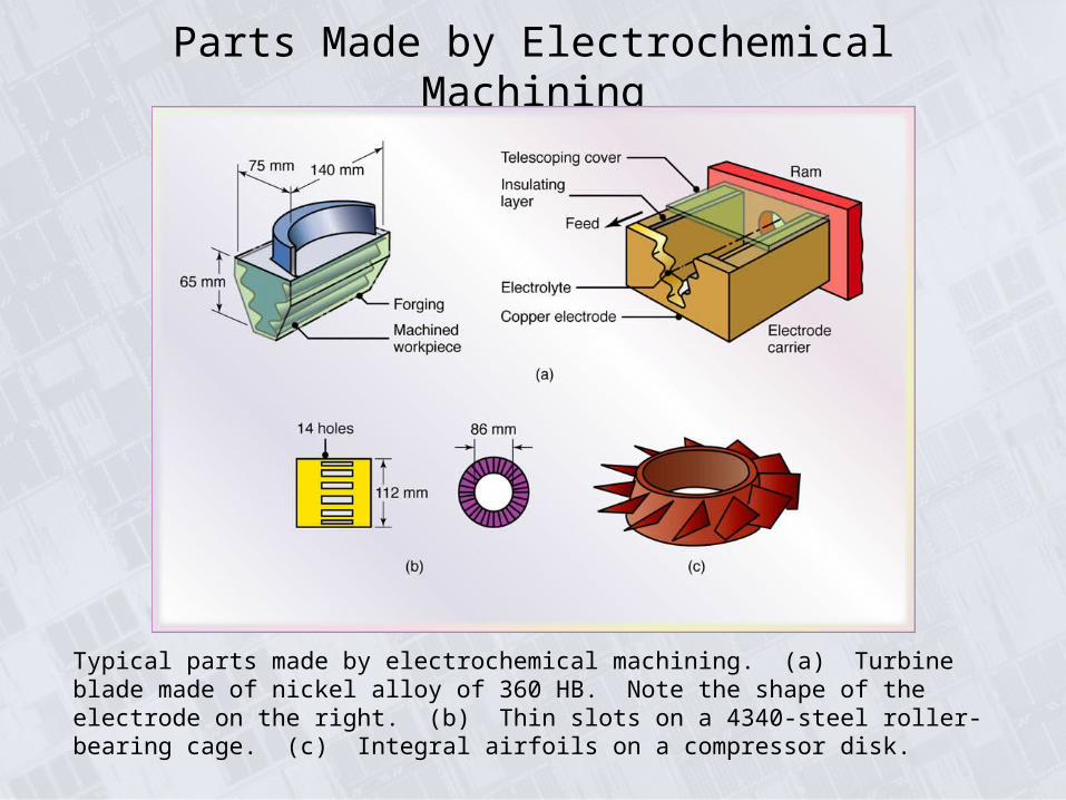
Typical parts made by electrochemical machining. (a) Turbine blade made of nickel alloy of 360 HB. Note the shape of the electrode on the right. (b) Thin slots on a 4340-steel roller-bearing cage. (c) Integral airfoils on a compressor disk.

Knee Implants
(a) Two total knee replacement systems showing metal implants (top pieces) with an ultra-high molecular-weight polyethylene insert (bottom pieces). (b) Cross-section of the ECM process as applies to the metal implant. Source: Courtesy of Biomet, Inc.

Electrochemical-Grinding Process
(a) Schematic illustration of the electrochemical-grinding process. (b) Thin slot produced on a round nickel-alloy tube by this process.

Electrical-Discharge Machining Process
(a) Schematic illustration of the electrical-discharge machining process. This is one of the most widely used machining processes, particularly for die-sinking applications. (b) Examples of cavities produced by the electrical-discharge machining process, using shaped electrodes. Two round parts (rear) are the set of dies for extruding the aluminum piece shown in front (see also Fig. 19.9b). (c) A spiral cavity produced by EDM using a slowly rotating electrode similar to a screw thread. (d) Holes in a fuel-injection nozzle made by EDM; the material is heat-treated steel. Source: (b) Courtesy of AGIE USA Ltd.
Stepped Cavities Produced by EDM Process
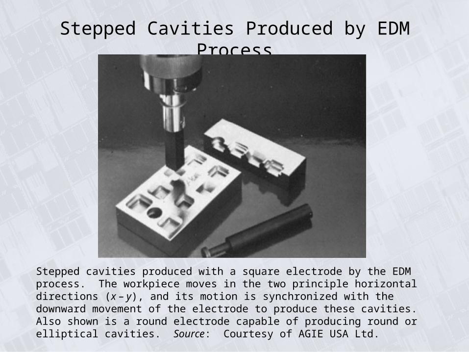
Stepped cavities produced with a square electrode by the EDM process. The workpiece moves in the two principle horizontal directions (x – y), and its motion is synchronized with the downward movement of the electrode to produce these cavities. Also shown is a round electrode capable of producing round or elliptical cavities. Source: Courtesy of AGIE USA Ltd.

The Wire EDM Process
Schematic illustration of the wire EDM process. As many as 50 hours of machining can be performed with one reel of wire, which is then discarded.
Metal removal rate :
MRR 4 104 ITw 1.23
where
I current in amperes
Tw melting temperature of workpiece, C

Wire EDM
(a) (b)
(a) Cutting a thick plate with wire EDM. (b) A computer-controlled wire EDM machine. Source: Courtesy of AGIE USA Ltd.

Laser-Beam Machining (LBM)
(a) Schematic illustration of the laser-beam machining process. (b) and (c) Examples of holes produced in nonmetallic parts by LBM. (d) Cutting sheet metal with a laser beam. Source: (d) Courtesy of Rofin-Sinar, Inc.

General Applications of Lasers in Manufacturing
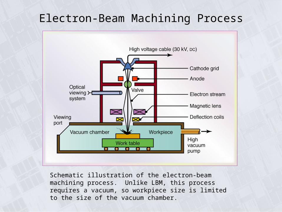
Electron-Beam Machining Process
Schematic illustration of the electron-beam machining process. Unlike LBM, this process requires a vacuum, so workpiece size is limited to the size of the vacuum chamber.
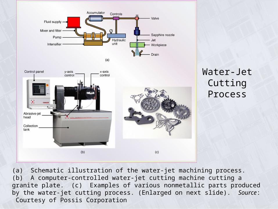
Water-Jet Cutting Process
(a) Schematic illustration of the water-jet machining process. (b) A computer-controlled water-jet cutting machine cutting a granite plate. (c) Examples of various nonmetallic parts produced by the water-jet cutting process. (Enlarged on next slide). Source: Courtesy of Possis Corporation

Nonmetallic Parts Made by Water-Jet Cutting
Examples of various nonmetallic parts produced by the water-jet cutting process. Source: Courtesy of Possis Corporation

Abrasive-Jet Machining
(a) Schematic illustration of the abrasive-jet machining process. (b) Examples of parts produced through abrasive-jet machining, produced in 50-mm (2-in.) thick 304 stainless steel. Source: Courtesy of OMAX Corporation.
(b)
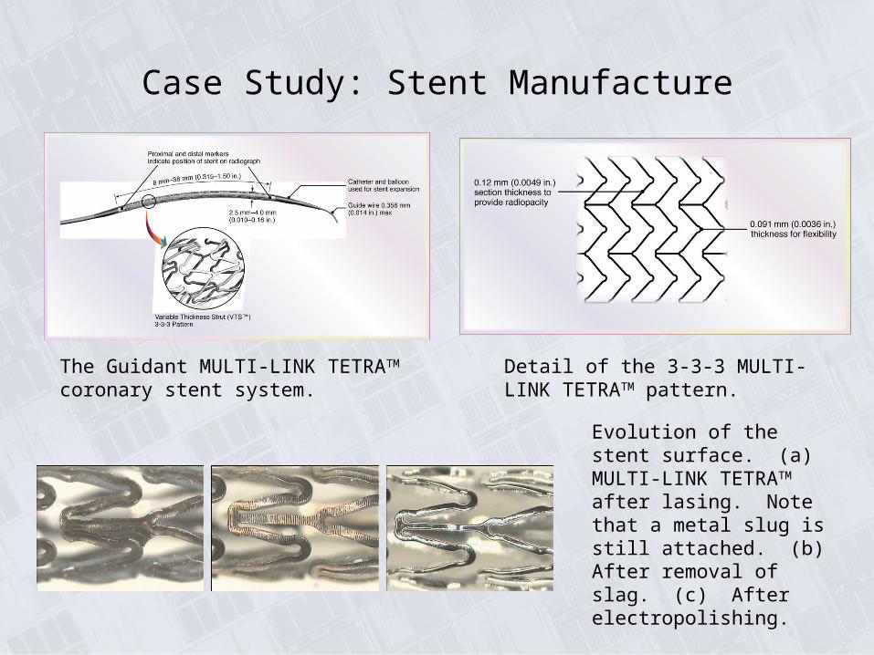
Case Study: Stent Manufacture
The Guidant MULTI-LINK TETRATM coronary stent system.
Detail of the 3-3-3 MULTI-LINK TETRATM pattern.
Evolution of the stent surface. (a) MULTI-LINK TETRATM after lasing. Note that a metal slug is still attached. (b) After removal of slag. (c) After electropolishing.
Related Documents