© Dontyne Systems Limited 2008 Dontyne Systems Limited is a company registered in England and Wales with company number 05973058 Registered office: 1 Simonside, Prudhoe, Northumberland, ENGLAND, NE42 6LJ VAT Registration Number: 902 9027 45 © Dontyne Systems Limited 2012 27 th April 2012 27 th April 2012 GATES Advanced Load Analysis Module V 4.6 History And Overview

Welcome message from author
This document is posted to help you gain knowledge. Please leave a comment to let me know what you think about it! Share it to your friends and learn new things together.
Transcript

© Dontyne Systems Limited 2008Dontyne Systems Limited is a company registered in England and Wales with company number 05973058Registered office: 1 Simonside, Prudhoe, Northumberland, ENGLAND, NE42 6LJVAT Registration Number: 902 9027 45
© Dontyne Systems Limited 2012
27th April 2012
27th April 2012
GATES Advanced Load Analysis
Module V 4.6
History And Overview

© Dontyne Systems Limited 2012GATES 4.6 - History and Overview
Introduction Background & Development
Application
Experimental Validation
Analysis Features
Advantages of GATES Program
Summary

© Dontyne Systems Limited 2012GATES 4.6 - History and Overview
GATES – Gear Analysis for Transmission Error and Stress
It is an FE based analysis package that calculates;
– Transmission Error (T.E.)– Load sharing between teeth– Surface Contact Stress and Root Bending Stress– Efficiency
Introduction

© Dontyne Systems Limited 2012GATES 4.6 - History and Overview
Background1990- 1992 The Design Unit (Newcastle Upon Tyne U.K.) identify the need
for a sophisticated loaded tooth contact analysis for gears
1992- 1997 A large number of different gears tested at many torques and alignments. Some of the results of which have been published
1997- 2006 Program is implemented using FEA by project founders and collaborators
2006- 2007 Dontyne Systems take over the development and marketing of GATES calculation as part of Load Analysis Model
2007- 2009 Development programs defined and implemented for the expansion of the GATES analysis and scope

© Dontyne Systems Limited 2012GATES 4.6 - History and Overview
ApplicationInitial Development in Marine propulsion systems
– GATES has been used to design gears for British Royal Navy

© Dontyne Systems Limited 2012GATES 4.6 - History and Overview
Contact Model
Link To ISO6336 Design and Rating

© Dontyne Systems Limited 2012GATES 4.6 - History and Overview
Contact Model
Flexible Profile and Lead Definition of 2D
and 3D Surface Topography

© Dontyne Systems Limited 2012GATES 4.6 - History and Overview
Contact Model
Links To Metrology Equipment To Define
Surface From Measured Data
3D Surface Measurement

© Dontyne Systems Limited 2012GATES 4.6 - History and Overview
Contact ModelMeasured Data Allows Effect of Bias on Measured Surface
to be Examined
Designed topology 3D Measured Topology inc bias

© Dontyne Systems Limited 2012GATES 4.6 - History and Overview
Contact Model
•Misalignment due to assembly or deflection
•Bearing Compliance
•Case Compliance
Operating Conditions

© Dontyne Systems Limited 2012GATES 4.6 - History and Overview
Analysis OptionsAnalysis Types:
– Contact stress– Contact load– Bending stressTensile and compressive – Transmission errorGeometric / Total– Power Loss

© Dontyne Systems Limited 2012GATES 4.6 - History and Overview
Analysis OptionsGraphic Presentation:
– 2D chart / 3D chart / Gear surface

© Dontyne Systems Limited 2012GATES 4.6 - History and Overview
Analysis OptionsMultiple Load Levels:
Detailed Tooth-To-Tooth(Plot can be used to derive FFT
Spectrum)
Harris Map Plot(Illustrates Change in Amplitude through load to identify optimum)

© Dontyne Systems Limited 2012GATES 4.6 - History and Overview
Analysis OptionsPower Loss On Tooth:

© Dontyne Systems Limited 2012GATES 4.6 - History and Overview
Analysis OptionsVariant #1 : Spur

© Dontyne Systems Limited 2012GATES 4.6 - History and Overview
Analysis OptionsVariant #2 : Helical

© Dontyne Systems Limited 2012GATES 4.6 - History and Overview
Analysis OptionsVariant #3 : Double Helical

© Dontyne Systems Limited 2012GATES 4.6 - History and Overview
Advantages of GATES Program– FEM calculation of tooth stiffness– Takes into account effect of increases of stress at gear tip– Exhibits change in behaviour due to twist of tooth– Extended contact that increases effective EAP and contact
ratio– Effect of manufacturing on root stress– Gear power loss and efficiency– Link to measured data– Validated results
© Dontyne Systems Limited 2012GATES 4.6 - History and Overview
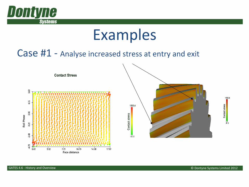
ExamplesCase #1 - Analyse increased stress at entry and exit

© Dontyne Systems Limited 2012GATES 4.6 - History and Overview
ExamplesCase #2 - Tip Stresses (Inadequate Tip Relief)

© Dontyne Systems Limited 2012GATES 4.6 - History and Overview
ExamplesCase #3 - Twist (dependent on where torque applied)

© Dontyne Systems Limited 2012GATES 4.6 - History and Overview
ExamplesCase #4 - Increase efficiency with surface modifications

© Dontyne Systems Limited 2012GATES 4.6 - History and Overview
Same 20° spur gear cut with different pressure angle hob (short lead hob)
20 degree 11 degree
ExamplesCase #5 – Effect of manufacturing on root strength

© Dontyne Systems Limited 2012GATES 4.6 - History and Overview
Deflected tooth
Un-deflected position
End of active profile
Contact continues beyond end of active profile off line of action as tooth releases load and rolls round on tip
Theoretical end of active profile
Actual end of active profile
Contact Stress
ExamplesCase #6 – Extended contact for tip loaded gears

© Dontyne Systems Limited 2012GATES 4.6 - History and Overview
Validation 1The following data is from an experimental study to validate the application of the GATES contact model:
– Marking patterns on actual gears are shown compared to predicted bearing load from GATES
– Good correlation is shown
Experimental data courtesy of:

© Dontyne Systems Limited 2012GATES 4.6 - History and Overview
Validation 1Gear Centres 91.5 mm
Gear Ratio 1.5:1
Wheel Ref Diameter 108.08
Pinion Ref Diameter 72.05
Face Width ~ 25 mm
Pinion Torque 100 – 373 Nm
Experimental data courtesy of:

© Dontyne Systems Limited 2012GATES 4.6 - History and Overview
Validation 1
Experimental data courtesy of:
Pinion 100 Nm Wheel 100 Nm

© Dontyne Systems Limited 2012GATES 4.6 - History and Overview
Validation 1
Experimental data courtesy of:
Pinion 213 Nm Wheel 213 Nm

© Dontyne Systems Limited 2012GATES 4.6 - History and Overview
Validation 1
Experimental data courtesy of:
Pinion 373 Nm Wheel 373 Nm

© Dontyne Systems Limited 2012GATES 4.6 - History and Overview
Validation 2The following data is from an experimental study to validate the application of the GATES Transmission error model:
– The aim was to reduce noise levels that arise from the transmission error (T.E.) at the gear mesh
– The T.E. Causes forces that propagate through the system and radiate noise
– A comparison is provided between single, double helical gears and optimised gears using the GATES program
Experimental data courtesy of:

© Dontyne Systems Limited 2012GATES 4.6 - History and Overview
Validation 2Gear Centres 400mm
Gear Ratio 3:1
Wheel Ref Diameter 600
Pinion Ref Diameter 200
Face Width ~ 200mm
Max Pinion Speed 6000rpm
Max Pinion Torque 15000rpm
Max Power 8 MW
Experimental data courtesy of:

© Dontyne Systems Limited 2012GATES 4.6 - History and Overview
Validation 2
Experimental data courtesy of:

© Dontyne Systems Limited 2012GATES 4.6 - History and Overview
Validation 2
33Specified AccuracyISO 1328-1/95 Grade
400400Centre Distance, a573.15183.15Root Diameter, df
612222Tip Diameter, da599.839199.946Ref. Diameter, d
200200Face Width, b28.728.7Ref. Helix Angle, βn
17.5°17.5°Ref Pressure Angle, αn
6.056.05Normal Module, mn87 29No of teeth, z
WheelPinion
Experimental data courtesy of:

© Dontyne Systems Limited 2012GATES 4.6 - History and Overview
Validation 2
None15μm CrowningNone20μm CrowningLead
Tip Relief – 10μmx5mm extentRoot Relief - none
Tip Relief – 10μmx5mm extentRoot Relief - none
Tip Relief – 10μmx10.5mm extentRoot Relief - none
Tip Relief – 10μmx10.5mm extentRoot Relief - none
Profile
WheelPinionWheelPinion
Flank BFlank A
Experimental data courtesy of:

© Dontyne Systems Limited 2012GATES 4.6 - History and Overview
Validation 2
Pinion Speed (rpm)
Pinion BearingLoad[N]rms
Flank A
Optimised
Single Helical
DoubleHelical
Experimental data courtesy of:

© Dontyne Systems Limited 2012GATES 4.6 - History and Overview
Validation 2Pinion BearingLoad[N]rms
Pinion Speed (rpm)
Flank B
Single Helical
Double HelicalOptimised
Experimental data courtesy of:

© Dontyne Systems Limited 2012GATES 4.6 - History and Overview
Summary Experimentally validated FE model FE analysis is a practical development tool
- Graphical view of analysis- Integration to other Dontyne software design tools- Integration to metrology equipment for increased
accuracy- Failure investigation and reverse engineering
Proven results for noise and vibration reduction Significant advantages over other calculation methods Continued development and experimental validation

© Dontyne Systems Limited 2012GATES 4.6 - History and Overview
SummaryPublished literature- “Ultra-Low Noise Gearbox” Hofmann D. & Haigh J, Transactions of INEC 2000, Atkins, Hamburg, 14-16 March 2000
- “High Speed Gears for Extreme Applications in Industrial and Marine Fields” Weiss T. & Hoppe F., Gear Technology, Sep-Oct 2007 p 68-74
- “Practical Production of Low Noise Gears”, Penning G., BGA Congress 2008, 20 November 2008
- “Optimisation of Gear Performance Through Surface Engineering”, Aylott C., BGA Congress 2008, 20 November 2008
- “Optimizing Gear Geometry for Minimum Transmission Error, Mesh Friction Losses and Scuffing Risk Through Computer Aided Engineering”, Fraser R., Shaw B, Palmer D. & Fish M. AGMA FTM09, 13-15 September 2009
- “Evaluation of Methods for Calculating Effects of Tip Relief on Transmission Error, Noise and Stress in Loaded Spur Gears”, Palmer D. & Fish M. AGMA FTM10, 2010

© Dontyne Systems Limited 2012GATES 4.6 - History and Overview
Contact UsEurope
+44 1661 833 828Asia
+61 35 975 0816
www.dontyne.com
Related Documents