10/7/2010 N. Al-Khirdaji, AZT ech Sr Consultant 1 2.4 Advanced Inspection Techniques and Best Practices • Guided wave ultrasonic long range inspection • vance p ase arrays or we nspect on Advanced Inspection Techniques • Ins pec tion Tec hni que s wit h Uniq ue arac er s cs: – May Use One or More ND T Technologies – Typically Comp uterized – Inspection Utili zes Electronic Detectio n and Processing – Requires Very Specialize d Training – May Locate and Size or Just Locate

Welcome message from author
This document is posted to help you gain knowledge. Please leave a comment to let me know what you think about it! Share it to your friends and learn new things together.
Transcript
7/16/2019 Advanced Inspection Techniques and Best Practices
http://slidepdf.com/reader/full/advanced-inspection-techniques-and-best-practices 1/33
10/7/20
N. Al-Khirdaji, AZTech Sr Consultant
2.4 Advanced Inspection
Techniques and Best Practices
• Guided wave ultrasonic long range inspection
• vance p ase arrays or we nspect on
Advanced Inspection Techniques
• Inspection Techniques with Unique
arac er s cs:
– May Use One or More NDT Technologies
– Typically Computerized
– Inspection Utilizes Electronic Detection and
Processing
– Requires Very Specialized Training
– May Locate and Size or Just Locate
7/16/2019 Advanced Inspection Techniques and Best Practices
http://slidepdf.com/reader/full/advanced-inspection-techniques-and-best-practices 2/33
10/7/20
N. Al-Khirdaji, AZTech Sr Consultant
Advanced Inspection Techniques
• Advance Inspection Techniques for RBI and
– Acoustic Emission
– Ultrasonic Corrosion Mapping
– Ultrasonic Weld Inspection
– EMATS
– Phased Array
– Digital Radiography
– Leak Detection
Limitations of Conventional Inspection
Techniques
• The impetus for the use of long range ultrasonics is that
ultrasonic thickness checks for metal loss due to corrosion or
erosion are highly localized , in that they only measure the
thickness of the area under the transducer itself.
• To survey a large area requires many measurements and access
to much of the surface of the component. Where access is
difficult or costly a detailed survey becomes unattractive
economicall conse uentl limited sam lin onl is carried
out. Similar restrictions apply to other methods of measuring
wall thickness, such as radiography, eddy currents etc..
• Partial inspection of this type is not effective for reliable
overall assessment as the probability of detection of defects in
uninspected areas is zero.
7/16/2019 Advanced Inspection Techniques and Best Practices
http://slidepdf.com/reader/full/advanced-inspection-techniques-and-best-practices 3/33
10/7/20
N. Al-Khirdaji, AZTech Sr Consultant
Guided Wave Ultrasonic Inspection
• Guided waves are a form of ultrasonic waves that
rave roug a oun e es spec men n s case, a
pipe), parallel to the boundaries (inner and outer
wall), while being guided by these same boundaries.
• Due to the nature of the waves and the testing
frequencies used, the technique can be used to scan
location, thereby negating the time-consuming type of
grid scans required by conventional techniques such
as UT and ET.
Guided Wave Ultrasonic Inspection
• The performance of the inspection depends on the
chosen kind, either extensional or torsional .
• Imperfections could arise from non-uniform strength of
excitation of the transducer elements, phase errors
between the signals at the adjacent rings, ovality of the
pipe, or circumferential variation of the wall thickness of
the pipe.• Any such imperfections could lead to the generation of
some of the other, unwanted, modes of the pipe; such
signals would appear as coherent noise, that is to say, they
could not be removed by averaging multiple signals.

7/16/2019 Advanced Inspection Techniques and Best Practices
http://slidepdf.com/reader/full/advanced-inspection-techniques-and-best-practices 4/33
10/7/20
N. Al-Khirdaji, AZTech Sr Consultant
Why use EMATs ?
Because In-Service Inspection is DIRTY
EMATs can tolerate adverse conditions
EMATs can be FAST
High Speed Screening – Global Inspections
Capable of covering Large areas
EMATs can inspect areas not normally
accessibleBuried or Hidden Regions can be reached with Guided Waves
Why use EMATs ?
• Pipeline Direct Assessments
-
• High Temperature Piping
• Vessel Inspection
• Weld Inspections
• Pipe Support Inspection
• re ea er u e nspec ons• Tank Inspections
– Weld location
– Soil to Air inspections
7/16/2019 Advanced Inspection Techniques and Best Practices
http://slidepdf.com/reader/full/advanced-inspection-techniques-and-best-practices 5/33
10/7/20
N. Al-Khirdaji, AZTech Sr Consultant
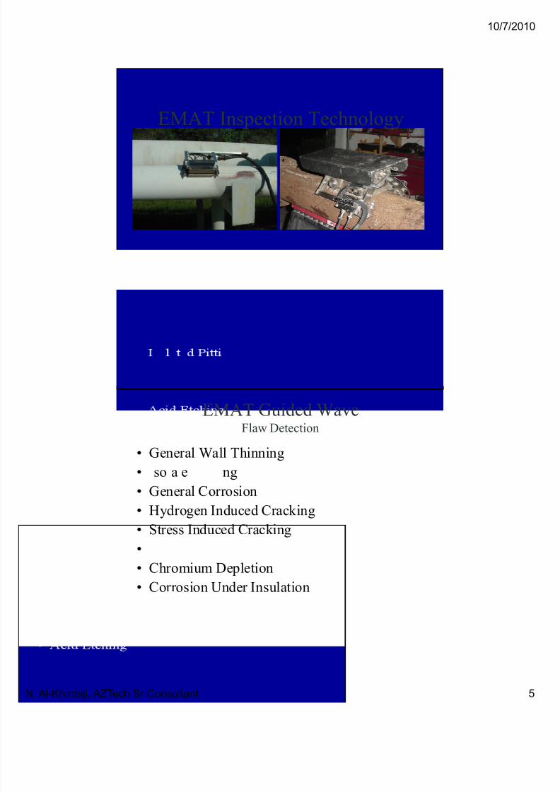
EMAT Inspection Technology
EMAT Guided WaveFlaw Detection
• General Wall Thinning
• so a e ng
• General Corrosion
• Hydrogen Induced Cracking
• Stress Induced Cracking
•• Chromium Depletion
• Corrosion Under Insulation

7/16/2019 Advanced Inspection Techniques and Best Practices
http://slidepdf.com/reader/full/advanced-inspection-techniques-and-best-practices 6/33
10/7/20
N. Al-Khirdaji, AZTech Sr Consultant
Localized Guided Wave
EMAT
Can bein
PLATES
EMAT
Or
PIPES
Or
CIRCUMFERENTIAL
Measurement Principals
• Time of Flight Velocity
• Transmitted Amplitude Attenuation
• Reflected Amplitude Reflection-
Coefficient
• Minimum Flaw Size proportional to Wave
front• Large Wave Front Long Distance/Lower
Sensitivity
• Small Wave Front Shorter Distance/Higher
Sensitivity

7/16/2019 Advanced Inspection Techniques and Best Practices
http://slidepdf.com/reader/full/advanced-inspection-techniques-and-best-practices 7/33
10/7/20
N. Al-Khirdaji, AZTech Sr Consultant
Volumetric Inspection
example in ½ inch (12mm) plateAmplitude Change vs Pit Volume
Round bottom holes
5mm, 10mm, 20mm, 30m m diameter
R2 = 0.947
80
Change in Transit Time vs Pit Volume
R2
= 0.8478
300
350
10
20
30
40
50
60
70
d A M P
50
100
150
200
250
d T
( n s e c )
0
0.00 3.00 6.00 9.00 12.00 15.00
Pit Volume (cc)
Guided Wave Propagation depends on the shape of the wave guide boundaries.
Fundamentally these are volumetric inspections.
Good Linear Correlation to VOLUME of round bottom holes
0
0.00 3.00 6.00 9.00 12.00 15.00
Pit Volume (cc)
EMATs Efficiently GenerateGuided Waves in Pipes
Transmitter Receiver
• The Guided Wave travels around the
circumference of a pipe.
• 100% Coverage is achieved from one location

7/16/2019 Advanced Inspection Techniques and Best Practices
http://slidepdf.com/reader/full/advanced-inspection-techniques-and-best-practices 8/33
10/7/20
N. Al-Khirdaji, AZTech Sr Consultant
Circumferential Guided Wave
• High Speed; Volumetric Inspection
• Performed in Pitch Catch,
• High Resolution Detection
– through transmission mode
• Attenuation Measures obstruction of beam
– i.e.. Pitting
• Velocity Measures thinning – i.e.. general corrosion
Geometry Affects Guided Wave Travel
Pits Scatter
Sound Attenuatio
n
Wave
Propagation
Thinning Speeds Up the Transit Time Change
ave

7/16/2019 Advanced Inspection Techniques and Best Practices
http://slidepdf.com/reader/full/advanced-inspection-techniques-and-best-practices 9/33
10/7/20
N. Al-Khirdaji, AZTech Sr Consultant
EMAT Guided Wave
Sample Amplitude “A”-Scan Presentation
EMAT Guided WaveSample E-Scan Presentation
• 10%
• 20%
• 30%
•
• 50%
7/16/2019 Advanced Inspection Techniques and Best Practices
http://slidepdf.com/reader/full/advanced-inspection-techniques-and-best-practices 10/33
10/7/20
N. Al-Khirdaji, AZTech Sr Consultant
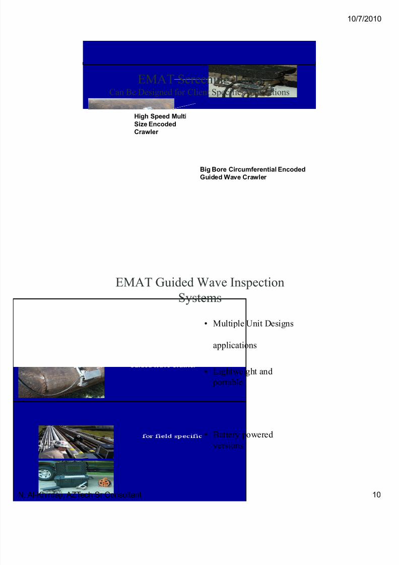
EMAT Screening ToolsCan Be Designed for Client Specific Applications
High Speed Multi
Big Bore Circumferential Encoded
Guided Wave Crawler
Size Encoded
Crawler
EMAT Guided Wave Inspection
Systems
• Multiple Unit Designs
applications
• Lightweight and
portable
• Battery powered
versions

7/16/2019 Advanced Inspection Techniques and Best Practices
http://slidepdf.com/reader/full/advanced-inspection-techniques-and-best-practices 11/33
10/7/20
N. Al-Khirdaji, AZTech Sr Consultant
Guided Waves
Can Provide Global Inspections• Piping, Tanks, Vessels, and Heater Tubes
•
• Repeatability
• Can be used In-service or During outages
• No Couplant needed
• High Speed Scanning
• Rough Surfaces
• Thick Coatings
• Numerous Scan Presentations• Portable Systems for easy access
EMAT Guided Wave Inspections
• Anything Inspectable fromma
• High Speed Screening Tool
• Remote Detection Capabilities
•• Relative Sizing Capable
• Absolute Sizing Capabilities in Limitedand Special Cases
7/16/2019 Advanced Inspection Techniques and Best Practices
http://slidepdf.com/reader/full/advanced-inspection-techniques-and-best-practices 12/33
10/7/20
N. Al-Khirdaji, AZTech Sr Consultant
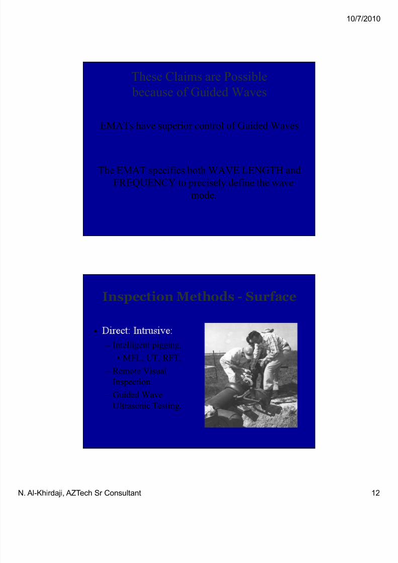
These Claims are Possible
because of Guided Waves
EMATs have superior control of Guided Waves
The EMAT specifies both WAVE LENGTH and
FREQUENCY to precisely define the wave
mode.
Inspection Methods - Surface
•
– Intelligent pigging,
• MFL, UT, RFT,
– Remote Visual
Inspection.
– Guided WaveUltrasonic Testing.
7/16/2019 Advanced Inspection Techniques and Best Practices
http://slidepdf.com/reader/full/advanced-inspection-techniques-and-best-practices 13/33
10/7/20
N. Al-Khirdaji, AZTech Sr Consultant
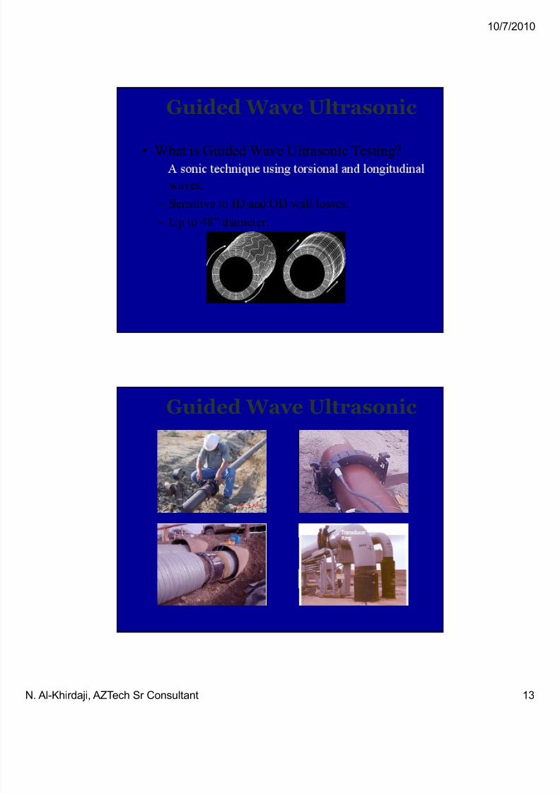
Guided Wave Ultrasonic
• What is Guided Wave Ultrasonic Testing?
–
waves.
– Sensitive to ID and OD wall losses.
– Up to 48” diameter.
Guided Wave Ultrasonic

7/16/2019 Advanced Inspection Techniques and Best Practices
http://slidepdf.com/reader/full/advanced-inspection-techniques-and-best-practices 14/33
10/7/20
N. Al-Khirdaji, AZTech Sr Consultant
Guided
WaveUltrasonic
Guided Wave Signals
(a) A typical weld is completely symmetric and shows up as only a
black curve.
(b) A typical corrosion patch is non-symmetric and is identified by the
presence of a red curve.

7/16/2019 Advanced Inspection Techniques and Best Practices
http://slidepdf.com/reader/full/advanced-inspection-techniques-and-best-practices 15/33
10/7/20
N. Al-Khirdaji, AZTech Sr Consultant
Guided Wave Ultrasonics
• Advantages:
– ,
– Non-intrusive, on-line and off-line,
– Up to 4,000 feet per day,
– Use on lined, coated, insulated or buried pipe,
– Portable,
– Repeatable results.
Guided Wave Ultrasonics
• Disadvantages:
– .
• Concrete lining,
• Coatings,
• Wrapping.
– Placement on pipe critical.
– pe con gura on cr ca . – Not quantitative data; sorting tool only.
– Follow-up with direct inspection required.

7/16/2019 Advanced Inspection Techniques and Best Practices
http://slidepdf.com/reader/full/advanced-inspection-techniques-and-best-practices 16/33
10/7/20
N. Al-Khirdaji, AZTech Sr Consultant
Guided Wave UT Inspection
• The benefits of this inspection include:
– o arge sec ons o p p ng can e nspec e rap y
– Minimal insulation removal
– Localized damage can be identified
– Previously inaccessible areas can be inspected especially
where consequences and likelihood of failure are high
– Point of contact corrosion areas can be ra idl ins ected
for piping systems resting on supports, eliminating the need
to “lift” pipes. The environmental impact and potential for further damaging suspect pipes during live “lifting” is
eliminated
Guided Wave Transducer System
Guided Ultrasonics solid transducer system is used for pipes up
to

7/16/2019 Advanced Inspection Techniques and Best Practices
http://slidepdf.com/reader/full/advanced-inspection-techniques-and-best-practices 17/33
10/7/20
N. Al-Khirdaji, AZTech Sr Consultant
Guided Wave Transducer System
Flexible, pneumatically clamped transducer system for larger
diameter pipe ( > NPS 8)
Guided Wave UT Inspection
7/16/2019 Advanced Inspection Techniques and Best Practices
http://slidepdf.com/reader/full/advanced-inspection-techniques-and-best-practices 18/33
10/7/20
N. Al-Khirdaji, AZTech Sr Consultant
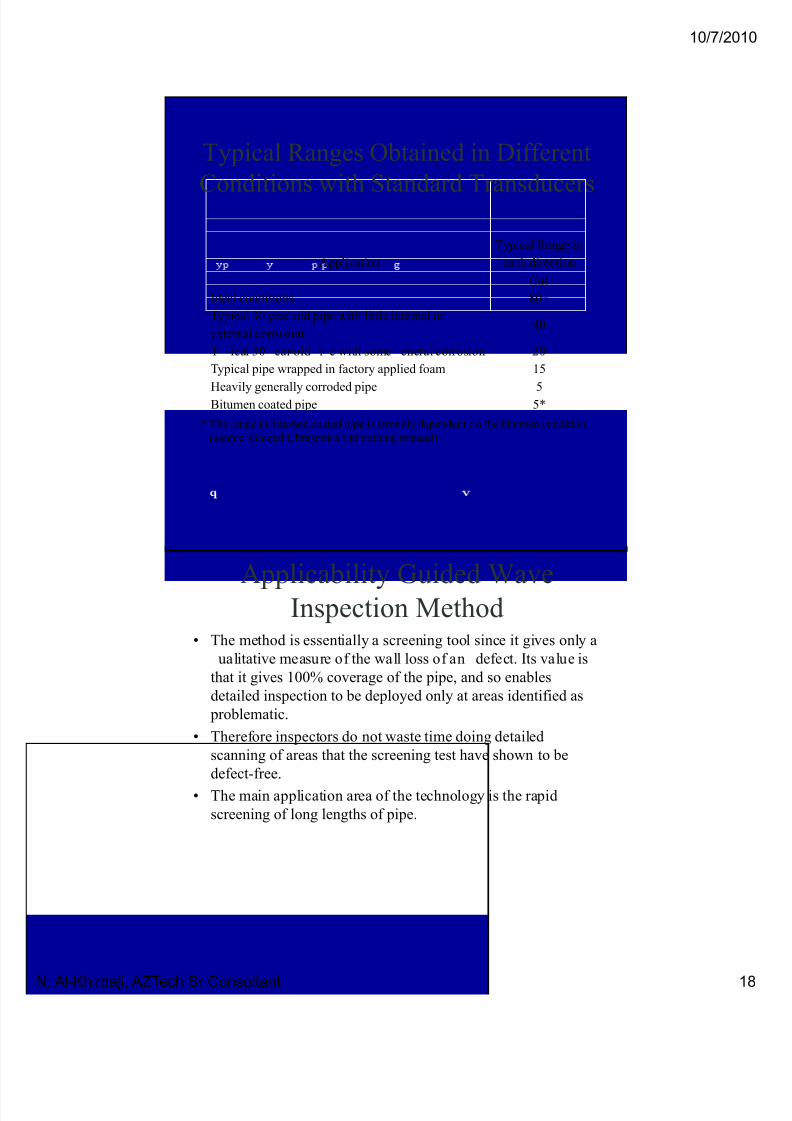
Typical Ranges Obtained in Different
Conditions with Standard Transducers
Application
Typical Range in
each direction
(m)
Ideal conditions 80+
Typical 30 year old pipe with little internal or
external corrosion40
T ical 30 ear old i e with some eneral corrosion 20
Typical pipe wrapped in factory applied foam 15
Heavily generally corroded pipe 5Bitumen coated pipe 5*
* The range in bitumen coated pipe is strongly dependent on the bitumen condition
(source: Guided Ultrasonics Ltd training manual)
Applicability Guided Wave
Inspection Method• The method is essentially a screening tool since it gives only a
ualitative measure of the wall loss of an defect. Its value is
that it gives 100% coverage of the pipe, and so enables
detailed inspection to be deployed only at areas identified as
problematic.
• Therefore inspectors do not waste time doing detailed
scanning of areas that the screening test have shown to be
defect-free.
• The main application area of the technology is the rapid
screening of long lengths of pipe.
7/16/2019 Advanced Inspection Techniques and Best Practices
http://slidepdf.com/reader/full/advanced-inspection-techniques-and-best-practices 19/33
10/7/20
N. Al-Khirdaji, AZTech Sr Consultant
Applicability Guided Wave
Inspection Method• The application of the technique to the detection of
where the feature density on the pipe system is low
(i.e. infrequent welds, tees, bends etc) and the
attenuation is low (no heavy general corrosion, no
highly attenuating coating), is relatively
strai htforward and the si nals obtained can be
interpreted by experienced NDT
Applicability Guided Wave
Inspection Method• It is particularly cost effective in difficult to access locations
such as:
– Sleeved road crossings
– Insulated pipes
– Wall penetrations
– Pipe racks
– Under supports
– Cases where rope access or scaffolding would be needed
for conventional inspection
7/16/2019 Advanced Inspection Techniques and Best Practices
http://slidepdf.com/reader/full/advanced-inspection-techniques-and-best-practices 20/33
10/7/20
N. Al-Khirdaji, AZTech Sr Consultant
Time-of-Flight Diffraction (TOFD)
•inspection technique.
• The TOFD technique is a fully computerizedsystem able to scan, store, and evaluate indicationsin terms of height, length, and position with agrade of accuracy superior to other ultrasonic
.
• It is based on diffraction of ultrasonic waves ontips of discontinuities, instead of geometricalreflection on the interface of the discontinuities.
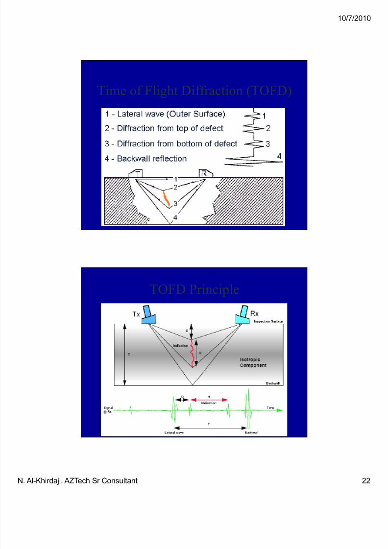
TOFD Principles
• The basic configuration for TOFD (Time Of g rac on ec n que cons s s o a separa e
ultrasonic transmitter and receiver.
• After emission of a compressional wave from atransmitter, the first signal to arrive at the receiver is lateral wave through upper surface.
• In the absence of defects the second si nal to arrive at the receiver is the backwall echo.
• The diffracted signal generated at the upper tip of a defect will arrive before the signal generated atthe lower tip of a defect.

7/16/2019 Advanced Inspection Techniques and Best Practices
http://slidepdf.com/reader/full/advanced-inspection-techniques-and-best-practices 21/33
10/7/20
N. Al-Khirdaji, AZTech Sr Consultant
TOFD PrincipleOn both sides of the weld an ultrasonic probe is positioned. One acts as an
emitter of ultrasound, the other as a receiver.
The longitudinal sound beam can encounter obstacles on its path, which cause
reflected and diffracted signals.
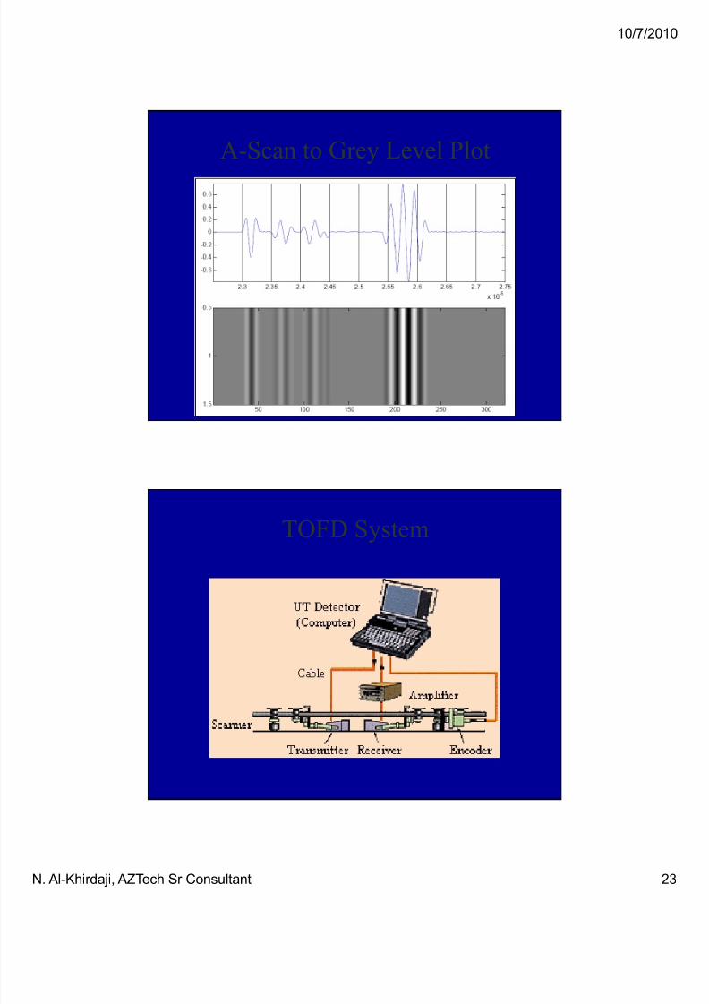
When the probes are moved parallel along the weld, the resultant waveforms are
digitized, stored on hard disk and displayed on the video-screen as a grey scale
image
The image build up is in effect a through sectional view of the weld examined
and can be used for accurate sizing and monitoring of indications.
Features of TOFD
– High Probability of Flaw Detection
– g ccuracy o aw ocat on easurement
– High Accuracy of Flaw Sizing in Length
– Weld Integrity to be observed on CRT in Real
Time as probes scan
– All inspection Data to be Digitised and Stored so
that the Data can be Recalled and Processed for In-Service Inspection
7/16/2019 Advanced Inspection Techniques and Best Practices
http://slidepdf.com/reader/full/advanced-inspection-techniques-and-best-practices 22/33
10/7/20
N. Al-Khirdaji, AZTech Sr Consultant
Time of Flight Diffraction (TOFD)
TOFD Principle
7/16/2019 Advanced Inspection Techniques and Best Practices
http://slidepdf.com/reader/full/advanced-inspection-techniques-and-best-practices 23/33
10/7/20
N. Al-Khirdaji, AZTech Sr Consultant
A-Scan to Grey Level Plot
TOFD System
7/16/2019 Advanced Inspection Techniques and Best Practices
http://slidepdf.com/reader/full/advanced-inspection-techniques-and-best-practices 24/33
10/7/20
N. Al-Khirdaji, AZTech Sr Consultant
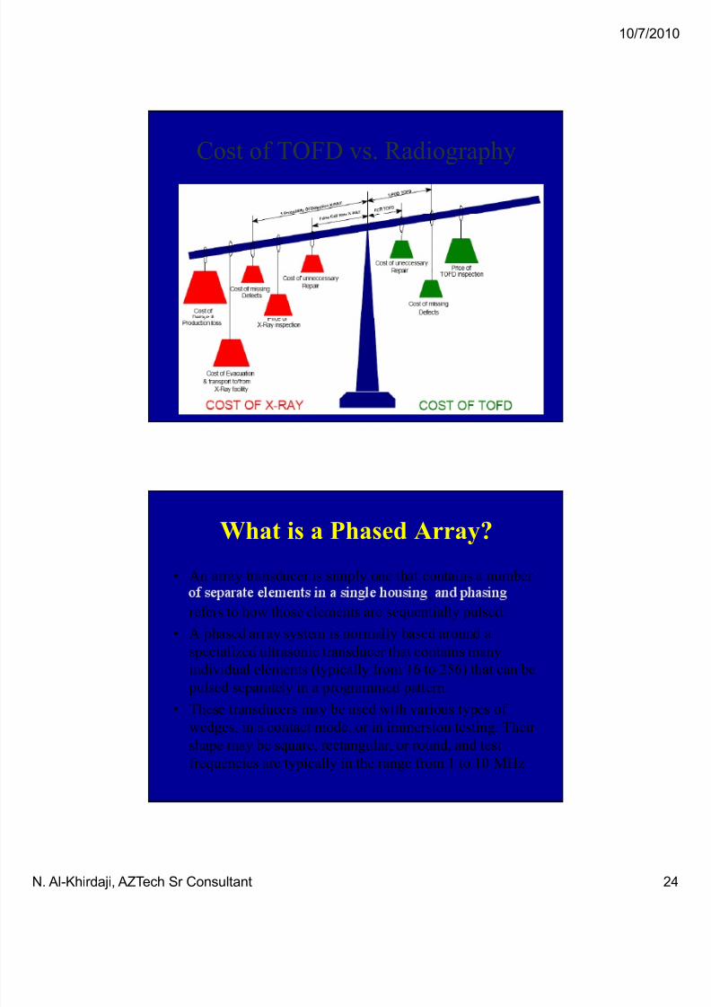
Cost of TOFD vs. Radiography
What is a Phased Array?
• An array transducer is simply one that contains a number
,
refers to how those elements are sequentially pulsed.
• A phased array system is normally based around a
specialized ultrasonic transducer that contains many
individual elements (typically from 16 to 256) that can be
pulsed separately in a programmed pattern.
• These transducers may be used with various types of wedges, in a contact mode, or in immersion testing. Their
shape may be square, rectangular, or round, and test
frequencies are typically in the range from 1 to 10 MHz

7/16/2019 Advanced Inspection Techniques and Best Practices
http://slidepdf.com/reader/full/advanced-inspection-techniques-and-best-practices 25/33
10/7/20
N. Al-Khirdaji, AZTech Sr Consultant
What is a Phased Array?
• Phased array systems pulse and receive from multiple
elements of an arra . These elements are ulsed in such a wa
as to cause multiple beam components to combine with each
other and form a single wave front traveling in the desired
direction. Similarly, the receiver function combines the input
from multiple elements into a single presentation.
• Because phasing technology permits electronic beam shaping
and steerin it is ossible to enerate a vast number of
different ultrasonic beam profiles from a single probe
assembly, and this beam steering can be dynamically programmed to create electronic scans.
Advantages of Phased Array Testing as
Compared with Conventional UT
The benefits of phased array technology over conventional UT
,
scan beams with a single transducer assembly.
Beam steering, commonly referred to sectorial scanning, can be
used for mapping components at appropriate angles. This can
greatly simplify the inspection of components with complex
geometry.

7/16/2019 Advanced Inspection Techniques and Best Practices
http://slidepdf.com/reader/full/advanced-inspection-techniques-and-best-practices 26/33
10/7/20
N. Al-Khirdaji, AZTech Sr Consultant
Advantages of Phased Array Testing as
Compared with Conventional UT• The small footprint of the transducer and the ability to
inspection of such components in situations where there
is limited access for mechanical scanning.
• Sectorial scanning is also typically used for weld
inspection. The ability to test welds with multiple
angles from a single probe greatly increases the
probability of detection of anomalies.
• Electronic focusing permits optimizing the beam shapeand size at the expected defect location, as well as
further optimizing probability of detection.
Advantages of Phased Array Testing as
Compared with Conventional UT
• The ability to focus at multiple depths also improves
inspections.
• Focusing can significantly improve signal-to-noise
ratio in challenging applications, and electronic
scanning across many groups of elements allows for
- .
7/16/2019 Advanced Inspection Techniques and Best Practices
http://slidepdf.com/reader/full/advanced-inspection-techniques-and-best-practices 27/33
10/7/20
N. Al-Khirdaji, AZTech Sr Consultant
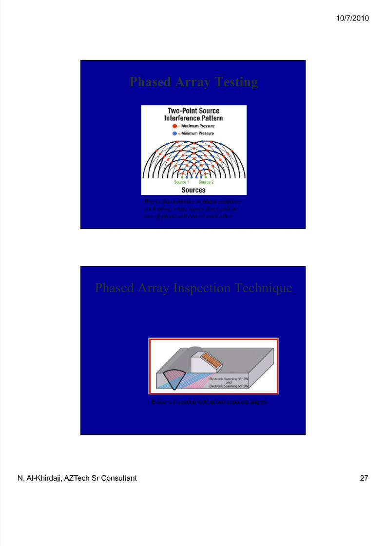
Phased Array Testing
Waves that combine in phase reinforce
each other, while waves that combine
out-of-phase will cancel each other.
Phased Array Inspection Technique
E-scans inspect a weld at two separate angles

7/16/2019 Advanced Inspection Techniques and Best Practices
http://slidepdf.com/reader/full/advanced-inspection-techniques-and-best-practices 28/33
10/7/20
N. Al-Khirdaji, AZTech Sr Consultant
Phased Array AUT Technology
The upper left corner in this figure illustrates the coverage options of
the technologies. The single element probe in the upper left corner
shows the limited region in the single beam available. In the upper
right, a TOFD pair is used in transmit-receive mode and the entire weld
volume is covered in a single pass.
The lower left illustrates
the phased array S-scan
created by sweeping from
from a single range of
elements (only 16 of the64 elements available are
used for this
configuration).
Pressure Vessel Inspection using
Phased Arrays

7/16/2019 Advanced Inspection Techniques and Best Practices
http://slidepdf.com/reader/full/advanced-inspection-techniques-and-best-practices 29/33
10/7/20
N. Al-Khirdaji, AZTech Sr Consultant
Encoded Arrays for Semi-Automatic
Inspections
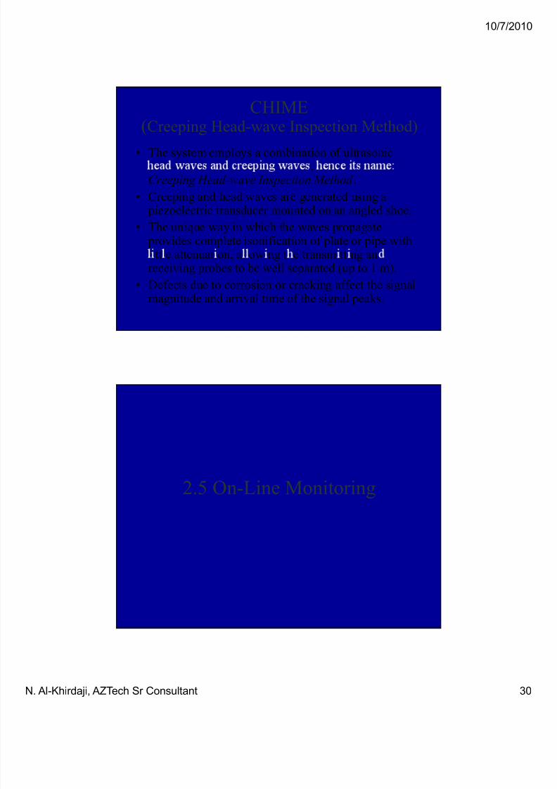
CHIME(Creeping Head-wave Inspection Method)
The new technique (AEA Technology) offers
lar e area sin le ass screenin which ins ects
the full volume between the probes (may be
separated by up to 1 m).
It can be used on both pipes and plate, and is
suitable for inaccessible geometries such as
clamps, saddles and pipe supports.
This eliminates the need for expensive shutdown
yet provides full information to indicate areas of corrosion and aid the prediction of plant lifetime.
7/16/2019 Advanced Inspection Techniques and Best Practices
http://slidepdf.com/reader/full/advanced-inspection-techniques-and-best-practices 30/33
10/7/20
N. Al-Khirdaji, AZTech Sr Consultant
CHIME(Creeping Head-wave Inspection Method)
• The system employs a combination of ultrasonic- ,
Creeping Head-wave Inspection Method .
• Creeping and head waves are generated using a piezoelectric transducer mounted on an angled shoe.
• The unique way in which the waves propagate provides complete isonification of plate or pipe with
tt e attenuat on, a ow ng t e transm tt ng anreceiving probes to be well separated (up to 1 m).
• Defects due to corrosion or cracking affect the signalmagnitude and arrival time of the signal peaks.
2.5 On-Line Monitoring

7/16/2019 Advanced Inspection Techniques and Best Practices
http://slidepdf.com/reader/full/advanced-inspection-techniques-and-best-practices 31/33
10/7/20
N. Al-Khirdaji, AZTech Sr Consultant
On-line Stress/strain Monitoring
Acoustic Emission Binary Localizer
A new Acoustic Emission s stem for on-lineStructural integrity monitoring of critical plantcomponents has been applied successfully for over one year.
AEBIL (Acoustic Emission Binary Localizer) isdesigned to identify and locate concentrated AE
scattered AE events, a typical condition
encountered in on-line monitoring of operating plant components.
Stress/strain Microprobe
• A portable in-situ Stress-Strain Microprobe (SSM)
- - -
behavior of several metallic materials, welds, and their
heat-affected-zones (HAZs) in various metallurgical
and damage conditions.
• The microprobe system utilizes an electro-
mechanicall -driven indenter hi h-resolution
penetration transducer and load cell, a personal
computer (PC), a 16-bit data acquisition /control unit,
and software.

7/16/2019 Advanced Inspection Techniques and Best Practices
http://slidepdf.com/reader/full/advanced-inspection-techniques-and-best-practices 32/33
10/7/20
N. Al-Khirdaji, AZTech Sr Consultant
Stress/strain Microprobe
• The automated ball indentation (ABI)
ec n que o e sys em s ase on
strain-controlled multiple indentations (at a
single penetration location).
• The technique permits measurement of yield
stren th stress-strain curve stren th
coefficient, and strain-hardening-exponent
(uniform ductility).
ACFM Technique - 1• The Alternating Current Field Measurement (ACFM)
techni ue is a non contactin electroma netic
technique for the detection of surface breaking
defects in conducting materials.
• The technique provides reliable detection and sizing
of cracks in metallic components and can be used
over paint, coatings and process related residue.
• The significant advantage over magnetic particle
inspection is that surface preparation is eliminated or
significantly reduced.

7/16/2019 Advanced Inspection Techniques and Best Practices
http://slidepdf.com/reader/full/advanced-inspection-techniques-and-best-practices 33/33
10/7/20
ACFM Technique - 2
–The ACFM probe induces a
uniform electric current into the
material to be inspected which
then produces a magnetic field
which will be disturbed and flow
around the edges of a defect if
present.
–Small detectors (sensors) are
built into probes which are used to
detect these magnetic field
disturbances.
ACFM Technique - 3
Two components of the magnetic field are measured,the Bx to estimate crack de th and Bz to estimatecrack length). These measurements together withsoftware algorithms are used to determine theaccurate length and depth of the defect.
Typical Bx and Bz traces
as the probe passes over a
crack
Characteristic ACFM
Butterfly plot
Related Documents