Advanced Configuration 420-0558G Contents Setting Up the Access Server ......................................................................... 1 Before you Begin ............................................................................................. 1 The Server’s Parameter Databases ................................................................ 2 Define and Set Commands ....................................................................... 2 Server Change Setting ............................................................................. 2 Retaining Parameters when Loading New Software ..................................... 3 Selecting Protocols and Features ................................................................... 4 Tip - Save Current Parameters Before Enabling Features/Protocols...... 5 Enabling UNIX Daemons ............................................................................... 8 Managing Server Resources ........................................................................... 9 How the Access Server Allocates Memory.................................................... 10 Text Pool Area ........................................................................................ 10 Memory Management Guidelines ................................................................ 11 Select Only Features and Protocols Necessary At Your Site ................. 11 Optimize Settings for the Enabled Features/Protocols .......................... 11 Upgrading Memory ................................................................................ 12 Parameters that Directly Affect Memory Allocation.................................... 13 Local Services ......................................................................................... 14 LAT Services ........................................................................................... 14 Domain Names ....................................................................................... 15 Identifying Memory Problems ...................................................................... 15 Error Messages ....................................................................................... 16 Server Displays....................................................................................... 16 Adjusting Parameters ................................................................................... 17 Server Node Limit .................................................................................. 18 Server Queue Limit ................................................................................ 19 Server Session Limit............................................................................... 19 Server Textpool Size ............................................................................... 20 Server Packet Count............................................................................... 21 Parameter Server Limit ......................................................................... 21 Port Typeahead Size ............................................................................... 22 Port Command Buffer Size ..................................................................... 23 Port IP TCP Window Size....................................................................... 23 PORT TCP/IP Outbound Address .......................................................... 24 Helpful Displays ........................................................................................... 24

Welcome message from author
This document is posted to help you gain knowledge. Please leave a comment to let me know what you think about it! Share it to your friends and learn new things together.
Transcript
Advanced Configuration
420-0558G
Contents
Setting Up the Access Server ......................................................................... 1Before you Begin............................................................................................. 1The Server’s Parameter Databases ................................................................ 2
Define and Set Commands ....................................................................... 2Server Change Setting ............................................................................. 2
Retaining Parameters when Loading New Software ..................................... 3Selecting Protocols and Features ................................................................... 4
Tip - Save Current Parameters Before Enabling Features/Protocols...... 5Enabling UNIX Daemons ............................................................................... 8Managing Server Resources ........................................................................... 9How the Access Server Allocates Memory.................................................... 10
Text Pool Area ........................................................................................ 10Memory Management Guidelines ................................................................ 11
Select Only Features and Protocols Necessary At Your Site................. 11Optimize Settings for the Enabled Features/Protocols .......................... 11Upgrading Memory ................................................................................ 12
Parameters that Directly Affect Memory Allocation.................................... 13Local Services ......................................................................................... 14LAT Services........................................................................................... 14Domain Names ....................................................................................... 15
Identifying Memory Problems ...................................................................... 15Error Messages....................................................................................... 16Server Displays....................................................................................... 16
Adjusting Parameters ................................................................................... 17Server Node Limit .................................................................................. 18Server Queue Limit ................................................................................ 19Server Session Limit............................................................................... 19Server Textpool Size ............................................................................... 20Server Packet Count............................................................................... 21Parameter Server Limit ......................................................................... 21Port Typeahead Size............................................................................... 22Port Command Buffer Size..................................................................... 23Port IP TCP Window Size....................................................................... 23PORT TCP/IP Outbound Address .......................................................... 24
Helpful Displays ........................................................................................... 24

ii
Show/Monitor Server Counters ..............................................................24Show/Monitor Server Status ..................................................................24Show/Monitor Server Alternate Status ..................................................26
Using TCP/IP Features.................................................................................27Configuring IP Routes ..................................................................................28
Host and Network Routes.......................................................................29Dynamic Routing ....................................................................................30Static Routing .........................................................................................30Define/Set Server IP Route.....................................................................31Clear/Purge Server IP Route ..................................................................32Show/List/Monitor Server IP Route .......................................................32
IP Traffic Filtering........................................................................................33Enabling IP Filtering..............................................................................34IP Traffic Filter Criteria .........................................................................34Traffic Filter Commands ........................................................................36
IPX Traffic Filters .........................................................................................40Traffic Filter Criteria..............................................................................40Determining the Most Specific Filter .....................................................41Traffic Filter Commands ........................................................................42
IPX-RIP Import/Export Filters .....................................................................44When There Are Multiple Matching Filters...........................................45Defining RIP Filters ...............................................................................45
SAP Import/Export Filters............................................................................47SAP Filter Criteria..................................................................................47When There Are Multiple Matching Filters...........................................48Defining SAP Filters...............................................................................48
Configuring Rotary Connections ..................................................................52Configuring the Rotary...........................................................................54Domain Name Storage............................................................................56Clear/Purge Server IP Rotary ................................................................57Show/List/Monitor Server IP Rotary......................................................57Show/List Domain...................................................................................57Clear/Purge Domain ...............................................................................57
Configuring RLOGIN Support......................................................................58Considerations ........................................................................................59Associated Commands ............................................................................59Defining RLOGIN Dedicated Services ...................................................60Defining RLOGIN Preferred Services ....................................................60Defining RLOGIN Transparent Mode....................................................61

iii
Network Management .................................................................................. 61Using SNMP ........................................................................................... 62Obtaining/Importing the Supported MIBs............................................. 64Defining a Trap Client............................................................................ 65Assigning SNMP Security Information (Optional) ................................ 65Miscellaneous SNMP Settings ............................................................... 69
Using Telnet to Access the Console Port ...................................................... 70Telnet Console Command....................................................................... 71Define/Set Server Console Logout.......................................................... 72
Loading through Internet Protocols ............................................................. 72Loading Images and Parameter Files .................................................... 74Configuring Load Protocols .................................................................... 75Directed TFTP ........................................................................................ 75Eliminating TFTP Broadcasts................................................................ 76Saving Parameters in the Permanent Database.................................... 76Dump Transmission ............................................................................... 77Define/Set Parameter Server ................................................................. 77Define/Set Server Parameter Server Check........................................... 77Show Server Status Display................................................................... 78
Using the Server as a Domain Name Server ............................................... 78Domain Name Resolution....................................................................... 78Obtaining/Storing Domain Names ......................................................... 79Domain Name Time-to-Live (TTL)......................................................... 80Define/Set Domain.................................................................................. 80Show/List Domain .................................................................................. 81Clear/Purge Domain............................................................................... 81
Using IP Reassembly .................................................................................... 82Using TCP Resequencing ............................................................................. 83Setting Up TN3270 Terminals...................................................................... 84
Translation Tables.................................................................................. 85Enabling the TN3720 Protocol...................................................................... 85
Enabling Extended Attributes................................................................ 86Defining TN3270 Devices ............................................................................. 87
Creating a New Device Type.................................................................. 88Using the TN3270 Command ................................................................. 88Defining a TN3270 TERMINALTYPE ................................................... 89Defining the TN3278TYPE .................................................................... 89Modifying the Keymap ........................................................................... 90IBM 3270 Display Station Functions for TN3270 Keymap ................... 91

iv
Modifying the Screenmap.......................................................................93Assigning a TN3270 Device to a Port .....................................................97Assigning a Default Port Number for TN3270 Sessions ........................98Assigning Userdata Strings for Telnet Dedicated Services ...................98Other Commands that Affect TN3270 Devices .................................... 102
Defining TN3270 Translation Tables ......................................................... 104Creating a New Translation Table ....................................................... 104Entering New Values Into the Table.................................................... 105Assigning a Translation Table to a Port............................................... 108Other Commands that Affect Translation Tables ................................ 109
Using Alternate Keymaps........................................................................... 111Defining the Alternate Keymaps.......................................................... 111Error Codes ........................................................................................... 113
Using Line 25 as a Status Line................................................................... 116Change the Terminal Display............................................................... 116Select the 25th Line.............................................................................. 116Activate the 25th Line .......................................................................... 117Status Line Information ....................................................................... 118
Local Printer Support ................................................................................. 119Setting Up Daemons ................................................................................... 120Enabling Daemons ...................................................................................... 121Using the Finger Daemon (fingerd)............................................................ 122Using the Route Daemon (routed) .............................................................. 125Using the rwho Daemon (rwhod)................................................................ 127Using Nested Menus................................................................................... 128
Memory Requirements ......................................................................... 128About the Nested Menu Feature ................................................................ 129
How the Server Obtains the Menu File ............................................... 131How a Port Obtains the Menus ............................................................ 131
Setting Up Script Servers ........................................................................... 131Creating the Nested Menu File .................................................................. 134
%menu_file............................................................................................ 135%menu_start n title .............................................................................. 135%menu_entry n entry-description command-string............................. 135%menu n ............................................................................................... 136%menu_wait.......................................................................................... 136%menu_noprompt ................................................................................. 137%menu_end........................................................................................... 137%menu_prompt prompt-text ................................................................. 137

v
%menu_continue prompt-text............................................................... 137%menu_top x text-string ....................................................................... 137%menu_up x text-string ....................................................................... 138%menu_exit x text-string ...................................................................... 138%menu_logout x text-string .................................................................. 138%menu_repaint x text-string ................................................................ 138
Using Comment Lines in the Menu File .................................................... 139General Guidelines ..................................................................................... 139Debugging the Menu File ........................................................................... 140Configuring the Server to Support Nested Menus..................................... 140
Server Settings ..................................................................................... 140Port Settings ......................................................................................... 142
Sample Nested Menu Files ......................................................................... 144Sample File 1 ........................................................................................ 144Sample File 2 ........................................................................................ 148
Using Scripts............................................................................................... 159How the Script Feature Works................................................................... 160Setting Up the Script Server ...................................................................... 161
Create the Script File ........................................................................... 164Writing the Script ....................................................................................... 164
The # Character.................................................................................... 166Directory Requirements ....................................................................... 167
Setting Up the Access Server to Use Scripts.............................................. 169Define/Set Port Script Echo.................................................................. 170Script, Set Port Script........................................................................... 170Clear/Purge Server Script Server ........................................................ 171Show/List/Monitor Server Script Server.............................................. 171
Script File Execution and Processing......................................................... 172Sample Scripts ............................................................................................ 174Using the Accounting Feature.................................................................... 175Enabling the Accounting Feature .............................................................. 176Enabling the syslogd Daemon .................................................................... 177
Defining Two syslogd Hosts on the Access Server............................... 178Information In the Account Log ................................................................. 179
The Default Account Log...................................................................... 179Memory Considerations........................................................................ 180
Sample Default Account Log ...................................................................... 181Enabling the Verbose Account Log............................................................. 181
Verbose Priority Number and Log File Location ................................. 182
vi
Clearing the Account Log ........................................................................... 184Associated Displays..................................................................................... 184
Show/Monitor Server Accounting......................................................... 184Show/List/Monitor Server Characteristics ........................................... 184Show/List Unit and Show/List/Monitor Server Alternate Status ........ 185
Maintaining Boot Records........................................................................... 185Viewing Initialization Settings ................................................................... 186Status of MX-1608A/1620/1640 Initialization Records ............................... 187Enabling and Disabling Protocols............................................................... 188Changing Protocols through Commands .................................................... 189
CARD, NVS, XMOP, and MOP Protocols............................................. 190CARD Protocol ...................................................................................... 190NVS Protocol......................................................................................... 190XMOP and MOP Protocols ................................................................... 190Changing the Software Filename......................................................... 191BOOTP and RARP Protocols ................................................................ 191DTFTP Protocol .................................................................................... 192
Resetting Parameters to Defaults............................................................... 194Using Security Features ............................................................................. 194Passwords.................................................................................................... 195
Login Password..................................................................................... 196Privilege Password................................................................................ 196Maintenance Password......................................................................... 197
Privilege Levels........................................................................................... 198Remote Authentication Dial In User Service (RADIUS)............................ 200
Understanding the RADIUS Authentication Process .......................... 201Using Kerberos Authentication .................................................................. 203Using SecurID Authentication ................................................................... 206
SecurID Client Features....................................................................... 206Using Internet Security .............................................................................. 208Controlling Access to Network Resources .................................................. 209
Port Access Setting ............................................................................... 209Limited View Protection for Network Resources ................................. 210Authorized LAT Service Groups........................................................... 211Password Protection for LAT Services ................................................. 211
Time Server Enhancement ......................................................................... 212RADIUS Security ........................................................................................ 214
Multiple Levels of Security................................................................... 214Challenge/Response Process ................................................................. 215
vii
Easy Installation and Integration ........................................................ 215Getting Started - RADIUS.......................................................................... 215
Configuring the RADIUS Server on the Host...................................... 216Configuring RADIUS on the Access Server ......................................... 216Configuring RADIUS Authentication on a Per-Port Basis .................. 219Access Server Service-Selection ........................................................... 221RADIUS Server-Selection..................................................................... 225Displaying RADIUS Server Parameters .............................................. 227Outbound Port Security ....................................................................... 230Radius Callback (Dialback) .................................................................. 230
Supported RADIUS Authentication Attributes.......................................... 235Limited vs Enabled............................................................................... 235
Defining RADIUS Accounting .................................................................... 238RADIUS Accounting Prerequisites ...................................................... 238Setting Up RADIUS Accounting .......................................................... 239Defining a UDP Port Number .............................................................. 240Defining the RADIUS Accounting Logging Attempts Limits .............. 240Defining RADIUS Accounting for Port Logins and Logouts................ 240RADIUS Accounting Client Operation................................................. 241Accounting Retry and Backoff Timer Process...................................... 242Canceling RADIUS Requests ............................................................... 244Viewing RADIUS Accounting Information .......................................... 245RADIUS Accounting Attributes ........................................................... 248RADIUS Log Messages......................................................................... 251
Getting Started - Kerberos ......................................................................... 255Set Up the Kerberos Authentication Servers....................................... 255Enable Kerberos Authentication.......................................................... 255Configure Kerberos Settings ................................................................ 256Kerberos Error Messages ..................................................................... 257PPP User Authentication via Kerberos................................................ 258Logins Without Kerberos...................................................................... 258
Getting Started - SecurID Client Setup ..................................................... 259Configuring the SecurID Client at the UNIX host .............................. 259Install Software that Supports the SecurID Client ............................. 260Enable the SecurID Feature ................................................................ 260Define SecurID Settings....................................................................... 261Configure Ports to Require SecurID Authentication ........................... 263SecurID Failure .................................................................................... 263SecurID - Entering New PIN Mode ..................................................... 263
viii
Show Server Securid Display ............................................................... 263Getting Started - Internet Security ............................................................ 264
Defining Internet Security Information for the Server ....................... 264Port Security ......................................................................................... 265Specifying the Security Mask............................................................... 267Direction and Access............................................................................. 268Internet Security Examples.................................................................. 270Controlling Outbound Access ............................................................... 271Controlling Inbound Access .................................................................. 272Removing Security Table Entries......................................................... 274Viewing IP Security Entries ................................................................. 274
Using Scripts to Enhance Network Security.............................................. 276Dialback Modem Scripts ....................................................................... 276
Dial-Up Security ......................................................................................... 278Dial-Back Security................................................................................ 278Time-Sensitive Passwords .................................................................... 279
APD Port Authentication Command .......................................................... 279AppleTalk Remote Access (ARAP) Notes.................................................... 280CCL Notes (Using Modem-Based Compression)......................................... 281Packet Rejection Message ........................................................................... 281Active User and Active Ports ...................................................................... 282SNMP .......................................................................................................... 282ITS NTASC RADIUS Support .................................................................... 282How the Server Obtains the Current Time ................................................ 282Obtaining the Time..................................................................................... 284
Appendix A - Compatibility Issues
Appendix B - DEC Software Install and Management Tools
Index

ix
Figures
Figure 1. IP Route......................................................................................... 28Figure 2 - Server IP Routes Display............................................................. 32Figure 3. IP Traffic Filter Example.............................................................. 38Figure 4. IPX Traffic Filter Example ........................................................... 43Figure 5. Rotary Connections ....................................................................... 53Figure 6. Server IP Rotary Display .............................................................. 57Figure 7. Connecting to Host through RLOGIN .......................................... 58Figure 8. Network Management through SNMP......................................... 63Figure 9. Telnet Connections to Console Ports ............................................ 70Figure 10. Loading through Internet Protocols ........................................... 73Figure 11. Show Domain Display ................................................................. 81Figure 12. Server TN3270 Display..............................................................110Figure 13. Server TN3270 Translationtable Display ..................................110Figure 14. Three-Level Menu Structure .....................................................129Figure 15. Sample Menu .............................................................................130Figure 16. Sample Script Server Directory Structure ................................132Figure 17. Sample Script Server Directory Structure ................................162Figure 18. Server Script Server Display .....................................................171Figure 19. Sample Accounting Display .......................................................181Figure 20. Verbose Account Log..................................................................182Figure 21. Server Loaddump Primary Characteristics - MX-1620.............186Figure 22. RADIUS Authentication Process ...............................................202Figure 23. Kerberos Realm..........................................................................204Figure 24. Kerberos Password Verification.................................................205Figure 25. IP Network .................................................................................270Figure 26. Server IP Security Display ........................................................275Figure 27. Port IP Security Display ............................................................275Figure 28. Show Server Display ..................................................................285

x
Tables
Table 1 - Memory Usage For Features and Protocols .................................... 6Table 2 - UNIX Daemons ................................................................................ 8Table 3 - Memory Usage for Various Session Types..................................... 12Table 4 - Server Settings that Affect Memory Usage................................... 13Table 5 - Server Session Limit, Server Text Pool ......................................... 13Table 6 - Port Settings that Affect Memory Usage....................................... 14Table 7 - Server Status Display Fields ......................................................... 25Table 8 - Server Alternate Status Fields ...................................................... 26Table 9 - Get/Set Client and Community Settings ....................................... 66Table 10 - IBM Display Station Functions ................................................... 91Table 11 - Screenmap Actions....................................................................... 94Table 12 - Special Values for Escape Sequences........................................... 95Table 13 - EBCDICTOASCII, USENGLSH Translation Table .................. 106Table 14 - ASCIITOEBCDIC, USENGLSH Translation Table .................. 107Table 15 - The %menu Commands ............................................................. 134Table 16 - Priority Numbers for Messages from UNIX Daemons .............. 183Table 17 - Protocols for Loading and Dumping .......................................... 188Table 18 - Privilege Levels.......................................................................... 198Table 19 - RADIUS Supported Attributes .................................................. 236Table 20 - RADIUS Supported Accounting Attributes ............................... 248Table 21. RADIUS-Related Server Accounting Messages.......................... 251
Preface
xi
This manual describes the setup and management of advanced Access
Server features. Its intended audience includes network, server, and UNIX
and VAX host system managers.
Conventions
This manual uses the following conventions:
• Keys that you press are represented using left and right angle brackets
(< and >). For example, the notation <CTRL> means that you press the
CTRL key; <A> means that you press the A key; and <RETURN> means
that you press the RETURN key.
• Unless otherwise specified, commands are executed when you press
<RETURN>.
• The manual uses the following typographical conventions:
Monospace Typeface indicates text displayed at a terminal(displays, messages, systemresponses, etc).
italics indicates variables in commandsand procedures.
• The command prompt for non-privileged and secure users is:
Xyplex>
The command prompt for privileged users is:
Xyplex>>

xii
This is the default user interface prompt; a server manager can specify a
different prompt, so the prompt in use at your site might
be different.
• The following typeface indicates user input in response to
system prompts:
Xyplex> connect
• The following default user prompts are used (different prompts might be
in use at your site):
VMS $UNIX/ULTRIX %UNIX/Ultrix Superuser #DOS C:\
If you have questions about this product...
At your convenience, please forward these to Xyplex at the
following addresses:
Internet Mail: [email protected]
United States Mail: Xyplex, Inc.295 Foster StreetLittleton, MA 01460
Attn: Manager, Customer Support
Advanced Configuration
0558 1
Setting Up the Access Server
This section describes steps that you must take before setting up access
server features. It covers the following topics:
• Getting started
• The server’s parameter databases
• Selecting protocols and features
• Enabling UNIX daemons
Before you Begin
Once you have completed the steps in the Getting Started Guide supplied
with your access server, you can set up the access server for your specific
needs. Some of the related tasks are covered in the rest of this section
Others are covered in later sections under the Basic Configuration or
Printers section).
Specify which protocols, features, and daemons are to be used.
Note that some servers do not have enough memory to support all of the
available features concurrently. Also, some features are disabled by default;
you must enable them if you plan to use them.
Reboot the access server after enabling features and protocols.
This allows all of the changes that you have made to take effect. Use theInitialize command to reboot the server (e.g., INIT DELAY 0).
Assign basic IP settings, if applicable. (This step does not apply to
LAT-only units.) The IP settings that you need to specify include:
• The server’s IP address and subnet mask
• Domain name server settings
Advanced Configuration
2 0558
• Other settings that enable the access server to communicate through IP
gateways, if needed.
Refer to “Setting Up TN3270 Terminals” for more information about
these settings.
The Server’s Parameter Databases
Access servers keep a permanent database of settings, which includes port
and server settings, a list of services offered at the server, and in some cases
destinations to which users can connect. When you reboot the server, the
contents of the permanent database are copied into memory to serve as an
“operational database.”
Define and Set Commands
Changes to the operational database are discarded when you reboot the
server or a user logs off from a port. Use a Define command to change
settings in the parameter file permanently. Use a Set command to change
parameters temporarily.
Server Change Setting
Changes to settings that you make through Define commands take
effect when you reboot the server. However, you can set the
Server Change setting to Enabled, in which case Define commands
take effect immediately.
Advanced Configuration
0558 3
Retaining Parameters when Loading New Software
To maintain your current parameters when you install a new software
diskette or memory card, follow these steps:
1. Insert the new diskette or memory card into the access server.
2. Issue a Define command, such as DEFINE PORT 1 TYPE ANSI. This
forces the server to update all parameters on the diskette or memory
card.
3. Wait a minute, then issue the SHOW PARAMETER SERVER or MONITOR
PARAMETER SERVER command. Check that the display shows “Storage
State: Idle” and “Status: Current.” For a Network 9000 720 module,
make sure that the CARD light is off.
4. Reboot the access server to load the new software version.
Advanced Configuration
4 0558
Selecting Protocols and Features
Xyplex Access Servers offer many features and network protocols more
than most sites require. The protocols and features that you use depends
on your network environment and the amount of memory installed in the
server. “Managing Access Server Resources” explains how to select the
appropriate features and protocols for your site.
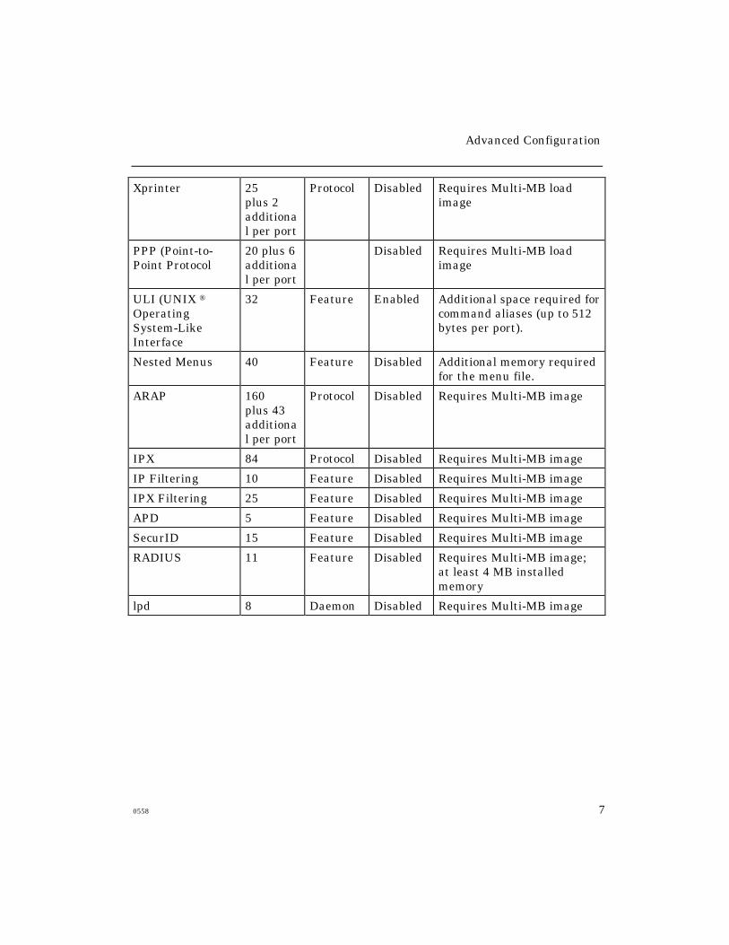
Table 1 lists various protocols and features and the amount of memory that
each requires. In general, if you do not require a particular protocol or a
feature, you should disable it to free up memory.
Use this command to enable or disable a protocol:
DEFINE SERVER PROTOCOL protocol-name [ENABLED]
[DISABLED]
Valid protocol values are listed in the first column of Table 1. If the server
requires a password to enable a protocol, it will prompt you for it. Contact
your Xyplex Sales Representative or Distributor for information about
obtaining the password(s).
Use this command to enable or disable a feature:
DEFINE SERVER feature [ENABLED]
[DISABLED]
Valid features are listed in the first column of Table 1.
Reboot the server after you have made all feature changes. When you
enable a feature, the server sets all related server or port settings to their
default values. When you disable a feature, the server changes all related
server or port settings to reflect the fact that the feature is disabled.
(For example, if you disable the Menu feature, the Port Menu setting is also
set to Disabled for each port.)
Advanced Configuration
0558 5
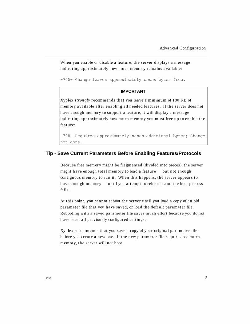
When you enable or disable a feature, the server displays a message
indicating approximately how much memory remains available:
-705- Change leaves approximately nnnnn bytes free.
IMPORTANT
Xyplex strongly recommends that you leave a minimum of 180 KB of
memory available after enabling all needed features. If the server does not
have enough memory to support a feature, it will display a message
indicating approximately how much memory you must free up to enable the
feature:
-708- Requires approximately nnnnn additional bytes; Change
not done.
Tip - Save Current Parameters Before Enabling Features/Protocols
Because free memory might be fragmented (divided into pieces), the server
might have enough total memory to load a feature but not enough
contiguous memory to run it. When this happens, the server appears to
have enough memory until you attempt to reboot it and the boot process
fails.
At this point, you cannot reboot the server until you load a copy of an old
parameter file that you have saved, or load the default parameter file.
Rebooting with a saved parameter file saves much effort because you do not
have reset all previously configured settings.
Xyplex recommends that you save a copy of your original parameter file
before you create a new one. If the new parameter file requires too much
memory, the server will not boot.

Advanced Configuration
6 0558
Table 1 - Memory Usage For Features and Protocols
Feature Name MemoryUsed in
Kilobytes
Type Default Comments
LAT 55 Protocol Enabled
TN3270 55 Protocol Disabled
SNMP 80 Protocol Disabled/Enabled
Disabled by default for 1 MBload images; Enabled bydefault for multi-MB loadimages.
KERBEROS 4KERBEROS 5
3050
FeatureFeature
DisabledDisabled
These features are mutuallyexclusive.
ACCOUNTING 0.5 to 90 Feature 0.5 Memory used depends onnumber of accountingentries.
MENU 7 Feature Disabled
MULTISESSIONS 12 Feature Disabled
INTERNETSECURITY
12 Feature Disabled
HELP 88(2+ MBunits)30 (1 MBunits)
Feature Disabled With V6.0 and later, fullHelp is disabled in multi-MBimages.
XREMOTE 22 Protocol Disabled Requires more memory foreach open session. RequiresMulti-MB load image.
Manager Load 375 Feature SeeComment
Enabled by default on AccessServer 720 and MAXserver1620/1640 Access Servers ifa memory card is present atinitialization. Disabled on1600/1450.
Advanced Configuration
0558 7
Xprinter 25plus 2additional per port
Protocol Disabled Requires Multi-MB loadimage
PPP (Point-to-Point Protocol
20 plus 6additional per port
Disabled Requires Multi-MB loadimage
ULI (UNIX ®OperatingSystem-LikeInterface
32 Feature Enabled Additional space required forcommand aliases (up to 512bytes per port).
Nested Menus 40 Feature Disabled Additional memory requiredfor the menu file.
ARAP 160plus 43additional per port
Protocol Disabled Requires Multi-MB image
IPX 84 Protocol Disabled Requires Multi-MB image
IP Filtering 10 Feature Disabled Requires Multi-MB image
IPX Filtering 25 Feature Disabled Requires Multi-MB image
APD 5 Feature Disabled Requires Multi-MB image
SecurID 15 Feature Disabled Requires Multi-MB image
RADIUS 11 Feature Disabled Requires Multi-MB image;at least 4 MB installedmemory
lpd 8 Daemon Disabled Requires Multi-MB image
Advanced Configuration
8 0558
Enabling UNIX Daemons
Xyplex Access Servers support several UNIX daemons, which are system
processes that run in background mode at network hosts. Daemons are
commonly used in UNIX environments and TCP/IP networks to exchange
information about network activity, or to manage resources such as printers
and peripherals.
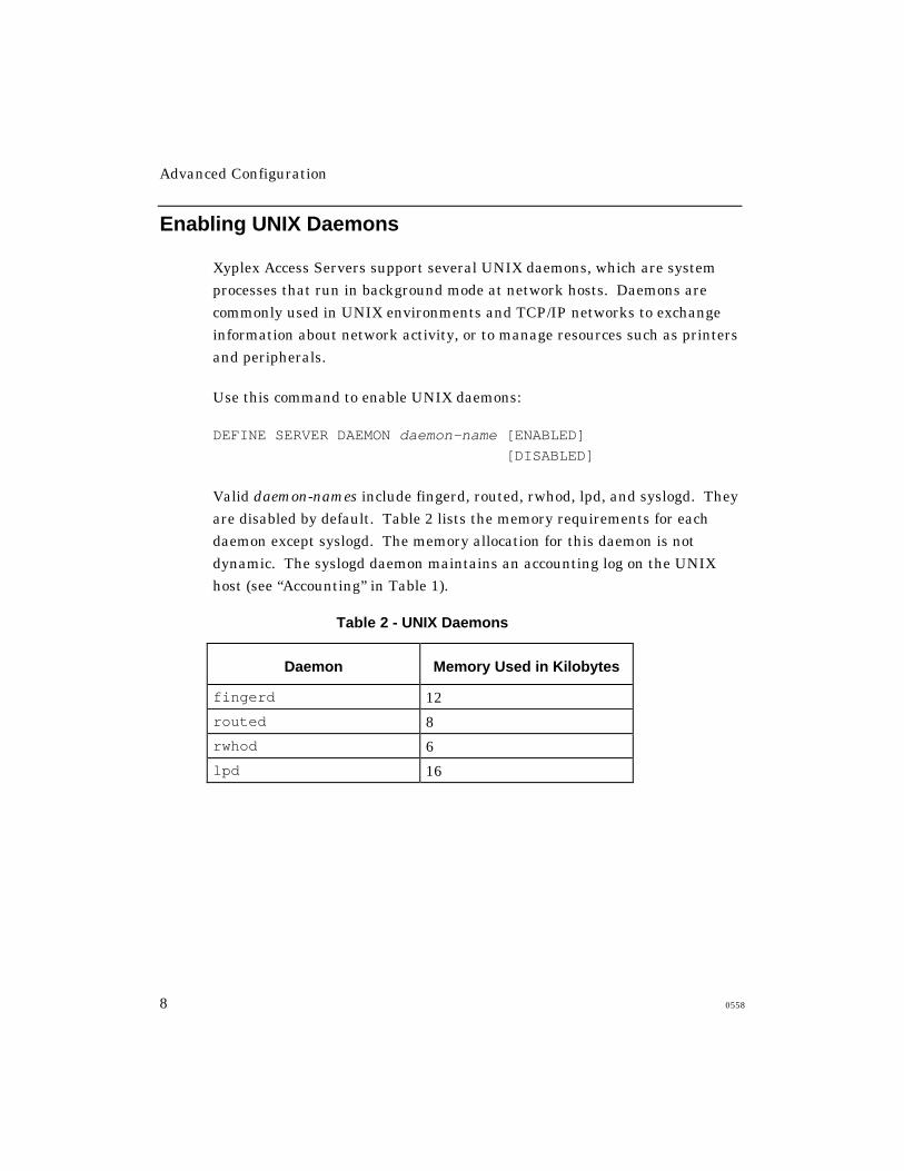
Use this command to enable UNIX daemons:
DEFINE SERVER DAEMON daemon-name [ENABLED]
[DISABLED]
Valid daemon-names include fingerd, routed, rwhod, lpd, and syslogd. They
are disabled by default. Table 2 lists the memory requirements for each
daemon except syslogd. The memory allocation for this daemon is not
dynamic. The syslogd daemon maintains an accounting log on the UNIX
host (see “Accounting” in Table 1).
Table 2 - UNIX Daemons
Daemon Memory Used in Kilobytes
fingerd 12
routed 8
rwhod 6
lpd 16
Advanced Configuration
0558 9
Managing Server Resources
An access server allocates (sets aside portions of) its memory to support
activities such as:
• Storing the software load image and parameters
• Supporting enabled features and protocols
• Storing information about sessions, network destinations, and the
connection queue
• Providing session resources, such as the type-
ahead buffer, for users
Since each site’s needs are different, the access server enables you to specify
how the memory is allocated. This section explains how to do so, and covers
these topics:
• How the access server allocates memory
• Strategies for managing memory
• Parameters that directly affect memory allocation
• Helpful displays

Advanced Configuration
10 0558
How the Access Server Allocates Memory
The server allocates memory when it boots. The server first loads its
software image, then the parameter file. It then checks the list of
configurable features and protocols in the parameter file, to determine
which ones are enabled. The server then frees up memory that is not being
used by the disabled features/protocols.
Next, the server allocates portions of memory for specific purposes, or to
store specific types of data. The server is then ready to run.
In general, further memory allocations occur on an as-needed basis. For
example, the server can allocate memory to store information about a LAT
service, or to provide resources such as the typeahead buffer when a user
wants to establish a new session. Similarly, the server frees up memory
when it is no longer needed, or when instructed by the server manager.
Text Pool Area
The text pool area is a permanently allocated portion of memory, the size of
which is fixed when the server boots. The server stores identification
strings for nodes, LAT services, and domain names in this area. When the
server boots, it immediately stores in the text pool space the identification
strings for the local services and domain names that are currently stored in
the permanent database.
The server fills the remaining text pool space as needed. (All other
information about nodes and services is stored in a non-text pool portion of
memory and is allocated when needed.)

Advanced Configuration
0558 11
Memory Management Guidelines
The goal of memory management is to balance the relationship among
features and protocols, performance, and cost-effectiveness. A proper
balance ensures that the server has enough resources for all users
when needed.
Select Only Features and Protocols Necessary At Your Site
Table 1 and Table 2 list protocols, features, and UNIX daemons that
you can enable, and the amount of memory that each requires.
“Setting Up the Access Server” explains how to enable/disable features,
protocols, and daemons.
To free up memory, you should disable the protocols and features that you
do not need. Some protocols or features require that another protocol also
be enabled. For example, SNMP, TN3270, and Kerberos require that
Telnet be enabled.
Help does not rely on other features or protocols.
Optimize Settings for the Enabled Features/Protocols
Server, port, and per-session settings can affect the amount of memory that
a feature uses, and the performance of sessions that make use of the
feature.
Typically, you do not need to change these settings after they are initially
defined. Often, the default values are adequate. However, you might need
to monitor and adjust some settings for better performance, and to ensure
that there is enough memory to support all users’ needs.

Advanced Configuration
12 0558
For example, Table 3 lists the amount of memory that various types of
sessions use when the related Server and Port settings are set to the
default values:
Table 3 - Memory Usage for Various Session Types
Session Type
(Using default PORT values)
Memory Used
Per Session (Bytes)
LAT session 1568, plus 1200 per virtual circuit
Telnet session 2320
TN3270 Model 2 session: noExtended Attributes
5104
TN3270 Model 2 session:with Extended Attributes
7008
TN3270 Model 5 session: noExtended Attributes
6720
TN3270 Model 5 session:with Extended Attributes
10352
Xremote Session 78300 for the initial X connectionand XDM login window, plus27000 for each additional window
Upgrading Memory
If you cannot enable every feature that you need and still have enough
memory available for users’ sessions, you might need to add memory to the
server or upgrade to a model that supports more memory. The Network
9000 Access Server 720 and MAXserver 800, 1600, 1620, and 1640 servers all
offer memory upgrade options.
Advanced Configuration
0558 13
Parameters that Directly Affect Memory Allocation
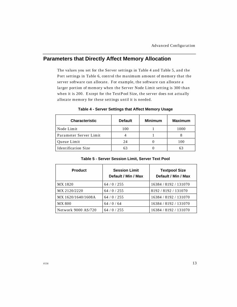
The values you set for the Server settings in Table 4 and Table 5, and the
Port settings in Table 6, control the maximum amount of memory that the
server software can allocate. For example, the software can allocate a
larger portion of memory when the Server Node Limit setting is 300 than
when it is 200. Except for the TextPool Size, the server does not actually
allocate memory for these settings until it is needed.
Table 4 - Server Settings that Affect Memory Usage
Characteristic Default Minimum Maximum
Node Limit 100 1 1000
Parameter Server Limit 4 1 8
Queue Limit 24 0 100
Identification Size 63 0 63
Table 5 - Server Session Limit, Server Text Pool
Product Session Limit
Default / Min / Max
Textpool Size
Default / Min / Max
MX 1820 64 / 0 / 255 16384 / 8192 / 131070
MX 2120/2220 64 / 0 / 255 8192 / 8192 / 131070
MX 1620/1640/1608A 64 / 0 / 255 16384 / 8192 / 131070
MX 800 64 / 0 / 64 16384 / 8192 / 131070
Network 9000 AS/720 64 / 0 / 255 16384 / 8192 / 131070
Advanced Configuration
14 0558
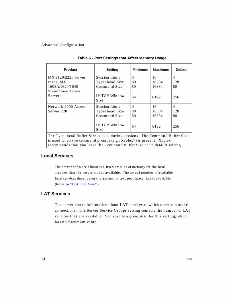
Table 6 - Port Settings that Affect Memory Usage
Product Setting Minimum Maximum Default
MX 2120/2220 servercards, MX1608A/1620/1640Standalone AccessServers
Session LimitTypeahead SizeCommand Size
IP TCP WindowSize
08080
64
161638416384
8192
412880
256
Network 9000 AccessServer 720
Session LimitTypeahead SizeCommand Size
IP TCP WindowSize
08080
64
161638416384
8192
412880
256
The Typeahead Buffer Size is used during sessions. The Command Buffer Sizeis used when the command prompt (e.g., Xyplex>) is present. Xyplexrecommends that you leave the Command Buffer Size at its default setting.
Local Services
The server software allocates a fixed amount of memory for the local
services that the server makes available. The actual number of available
local services depends on the amount of text pool space that is available.
(Refer to “Text Pool Area”.)
LAT Services
The server stores information about LAT services to which users can make
connections. The Server Service Groups setting controls the number of LAT
services that are available. You specify a group-list for this setting, which
has no maximum value.
Advanced Configuration
0558 15
Domain Names
For domain names, information other than identification strings is stored in
non-text pool memory. The server software allocates this memory whenever
it stores a domain name. The amount of non-text pool space used to store
domain name information depends on the number of domain names being
stored, and text pool limitations.
Table 5 lists the default, minimum, and maximum values for the session
limit and text pool size for various server models. This table assumes that
the server has the basic amount of installed memory. The Show Server
Characteristics display shows the current values for these settings.
Identifying Memory Problems
If there is not enough memory allocated for a setting, users might not be
able to connect to nodes or services because the memory limit has been
reached. If too much memory is allocated, the server might not have
enough memory for other purposes. For example, if you allocate too much
memory for the Node Limit setting, the server might not be able to allocate
an adequate Typeahead Buffer.
The section “Adjusting Parameters” describes how to adjust various server
and port parameters to meet your needs.
Advanced Configuration
16 0558
Error Messages
The server software generates error and status messages when too much
or too little memory is allocated for a setting. For example, when a user
attempts to establish a new session or connect to a node or service that is
normally available, the following messages might appear:
-710- Node node-name not known
-711- Service service-name not known
-719- Insufficient resources to complete operation
-772- Queued access failed, error or no response from
service
The first two messages might indicate that the server does not have enough
memory to store the unknown node or service name. The third message
might indicate that the server has prevented an operation because too much
memory had been allocated already. The last message might indicate that
the connection queue is full.
Server Displays
Certain server displays also indicate memory allocation problems. For
example, the following displays indicate when users are unable to locate a
node, service, or a domain name possibly indicating that you need to
adjust the memory allocation:
SHOW/MONITOR DESTINATIONS
SHOW/MONITOR DOMAIN
SHOW/MONITOR NODE
SHOW/MONITOR SERVICE
The section “Helpful Displays” describes the useful information in
these displays.

Advanced Configuration
0558 17
Adjusting Parameters
This section describes the settings that affect memory allocation and
explains how to change settings to free up memory.
In addition to adjusting these settings, you can use the following
procedures to free up memory or text pool space, or to change a server’s
memory setup.
% Memory Used Check the % Memory Used field of the Show Server
Status display whenever the server uses the maximum amount of memory
for a given resource (e.g., the Typeahead Buffer). If the maximum %
Memory Used is lower than 80 - 90 percent, you can usually correct the
problem by increasing the value for the setting that controls that resource.
If the maximum % Memory Used is already very high, you should probably
consider freeing up memory elsewhere as well.
Server Identification Size Decrease the storage requirements for
identification strings for local services, LAT services offered on the network,
nodes, and domain names. This releases text pool space so that the server
can store information about additional services, nodes, and domain names.
To do this, you can change the value of the Server Identification Size setting
or use shorter service, node, and domain names.
LAT Service Groups Restrict the number of LAT service groups that
the server uses; only use groups that users actually need. This limits the
number of LAT services and nodes that offer services. This change is
most helpful on a busy server that is part of a large network. Restricting
the number of LAT groups results in more text pool and non-text pool
space, and more efficient use of LAT virtual circuits.
Typeahead Buffers Check that the typeahead buffers are not
unnecessarily large. This releases memory for other needs.
Advanced Configuration
18 0558
Command Buffers Xyplex recommends that you leave the Command
Buffer Size at its default setting (80). You typically do not need to increase it
even if you need to increase the Typeahead Size.
Local Services Move a local service to a less heavily loaded server. This
releases small amounts of both text pool and non-text pool memory.
Packet Buffers Some features and network protocols, such as IP
reassembly, Xremote, SLIP, and PPP, require a large number of packet
buffers for ideal performance. If you are running one of these protocols
and experience poor performance, you should increase the packet buffer
count. PPP requires five packet buffers for port speeds less than 57.6
Kbps and 10 buffers for speeds of 57.6 Kbps or greater. SLIP always
requires 10 packet buffers.
TCP Window Size The Port IP TCP Window Size setting specifies the size of
the TCP window used during a session. If you define a window size that is
too large, the server might not have enough memory to support the usual
number of sessions.
Server Node Limit
If users are unable to connect to a node that should be available, or cannot
locate a node or service in a Show Node, Show Service, or Show
Destinations display or if the Show Server Status display indicates
Discarded Nodes or Resource Errors you should check the Show Server
Alternate Status display and the Reachable Nodes and Connected Nodes
fields of the Server Status display.
If the “highest” load is the same as the “maximum” load in the Reachable
Nodes field, the Server Node Limit setting might be set too low. If the
highest load is less than the maximum load, then the Server Textpool Size
might be set too low.
Advanced Configuration
0558 19
The Server Alternate Status display also indicates whether there is a
problem with text pool memory or non-text pool memory.
The Connected Nodes field in the Server Status display shows the number
of service nodes to which the server has established a LAT virtual circuit. If
the “current” value is the same as the “maximum” value, the server will not
permit a user to connect to another node.
If this is causing connection failures, you do not have a memory allocation
problem. To eliminate this problem, decrease the number of virtual circuits
that the server needs to establish, by moving users who usually connect to a
given node to a different server.
Server Queue Limit
When the Solicitations Rejected and Solicitations Accepted fields of the
Show Server Counters display indicate a large number of rejected queued
connection requests relative to the number of accepted requests check
the Queue Limit field of the Server Status display. If the “high” number of
queue entries in this field is the same as the “maximum” number, you might
need to increase the Server Queue Limit setting.
If the number is lower, connection requests might be failing for other
reasons. Otherwise, if you have noticed problems with other resources, you
might need to lower the value for the Server Queue Limit setting and raise
the value for the setting with which you are having the problem.
Server Session Limit
The Session Limit setting determines the maximum number of active
sessions the server can support concurrently. If users are unable to make
additional connections because the server has reached this limit or
because of a resource limitation the Session Limit might be set too low.
Check the Connected Sessions and Resource Error fields of the Show Server
Status display.
Advanced Configuration
20 0558
The Session Limit might be too low if the “highest” load equals the
“maximum” allowed. If the highest load is less than the maximum allowed,
and there are resource errors, you must free up additional memory to allow
for additional sessions.
Server Textpool Size
You control the size of the text pool area through the Server Textpool Size
setting. Since the text pool area is permanently allocated, you reduce the
amount of memory available for non-text pool memory when you increase
the size of this area. Also, lengthy identification strings can fill up the text
pool space and limit the number of nodes, services, and domain names
available to users.
If users cannot connect to a node or service that should be available, or are
unable to locate a node or service in a Show Node or Show Service display
or if the Show Server Status display indicates that “Discarded Nodes” or
“Resource Errors” have occurred, check the Show Server Alternate Status
display. If this display indicates that there have been “Free Text Pool”
errors, you should increase the Textpool Size.
If the Show Server Alternate Status display indicates that there have been
“Free Memory” failures, you should decrease the Textpool Size. If this is
not possible, consider reducing the size of the node and service identification
strings that must be stored in the text pool area. You can do this for node
names, domain names, local services, and LAT services offered by other
hosts and servers on the network.
Advanced Configuration
0558 21
Server Packet Count
Some features and network protocols, such as IP reassembly, Xremote, and
PPP, require a large number of packet buffers for ideal performance. If you
are running one of these protocols, and have experienced poor performance,
you should increase the packet buffer count through the following
command:
DEFINE SERVER PACKET COUNT packet-buffers
You can specify a packet-buffers value from 80 to 1088 for units with 2+ MB
of memory, and 80 to 160 for units with less than 2 MB of memory. The
default is 80.
Increasing the number of packet buffers can improve performance and
response time, but doing so will decrease the amount of available free
memory. The Show/Monitor Server Alternate Status display lists the
number of packet buffers being used and the maximum number available.
Parameter Server Limit
A server does not require much memory to store information about
parameter servers. If a heavily used server is unable to store information
about all eligible parameter servers, its Server Parameter Server Limit
setting is set too low. You can adjust the setting to match the number of
available parameter servers in your network, through the following
command. The maximum value for the setting is eight; the default is four.
DEFINE SERVER PARAMETER SERVER LIMIT number
If there are more than eight parameter servers in your network, you can
use the Set Parameter Server command to define specific parameter
servers, and the Clear Parameter Server command to remove other
parameter servers.
Advanced Configuration
22 0558
Port Typeahead Size
The Port Typeahead Buffer can contain between 80 and 16384 characters.
The default buffer size, 128 bytes, is adequate for most situations. You only
need to increase this value if an application requires it (e.g., certain
VAX/VMS applications).
VAX/VMS Typeahead Buffers
VAX/VMS terminal sessions use a separate typeahead buffer or alternate
typeahead buffer, which is specified through VMS SYSGEN settings. If
the size of the server typeahead buffer is larger than the VAX typeahead
buffer, the VAX typeahead buffer can overrun during data transfers.
During asynchronous port use, this overrun might cause the VAX session to
issue ASCII BELL characters to the server, rather than XOFF characters.
This is most noticeable when a user continuously presses an arrow key
while using an editor, or when using an asynchronous file transfer protocol,
such as XMODEM.
If this problem occurs, the VAX system manager can specify a
typeahead buffer size, or alternate typeahead buffer size, that is large
enough to support packets sent by the server and the asynchronous
file transfer protocol.
For example, the XMODEM software package properly transfers binary
files from a host to a PC when using a typeahead buffer size of 512
characters. On a system with VMS 5.0, the VMS system manager would
run the SYSGEN program, enter the following commands from the
SYSGEN> prompt, and then reboot the system:
SYSGEN> SET TTY_TYPAHDSZ 512
SYSGEN> WRITECURRENT

Advanced Configuration
0558 23
When you use an asynchronous file transfer protocol, you can increase the
server typeahead buffer to match the VMS typeahead buffer size through
the Set Port Typeahead Size command. However, since the larger VMS
typeahead buffer applies to all terminals, increasing its size will use more of
the computer’s memory.
Port Command Buffer Size
The Port Typeahead Buffer can contain between 80 and 16384
characters. The default buffer size, 80 bytes, is enough for most uses.
Xyplex recommends that you leave the default setting intact even if
you need to increase the Typeahead Buffer Size.
This setting controls the number of characters that can be buffered
(temporarily stored) at the command prompt (e.g., Xyplex>) before
overruns occur. It differs from the port typeahead setting, which is used
during sessions.
Port IP TCP Window Size
The Port IP TCP Window Size setting specifies the size of the TCP window
used during a session. Valid values are whole numbers between 64 and
8192. The default value is 256. If you define a window size greater than
256, the server might not have enough memory for the usual number of
sessions. A typical TCP/IP session requires about:
[1600 + (3 * TCP_window_size)] bytes
The window size that is in effect when a session begins remains in effect for
the entire session.

Advanced Configuration
24 0558
PORT TCP/IP Outbound Address
This setting allows each serial port on the access server to have a unique IP
address for outbound connections. The command is:
DEFINE/SET PORT IP TCP OUTBOUND ADDRESS [ip-address]
If you set this feature on a port, the IP address is used for all outbound
connections, if this feature is not set, then the access server’s IP address is
used for outbound connections.
Helpful Displays
This section describes displays that provide useful information when you
are monitoring memory usage.
Show/Monitor Server Counters
This display shows statistics about server activity, and indicates when
errors have occurred. Important fields include:
• Solicitations Accepted
• Solicitations Rejected
Refer to “Server Queue Limit” for descriptions of these fields.
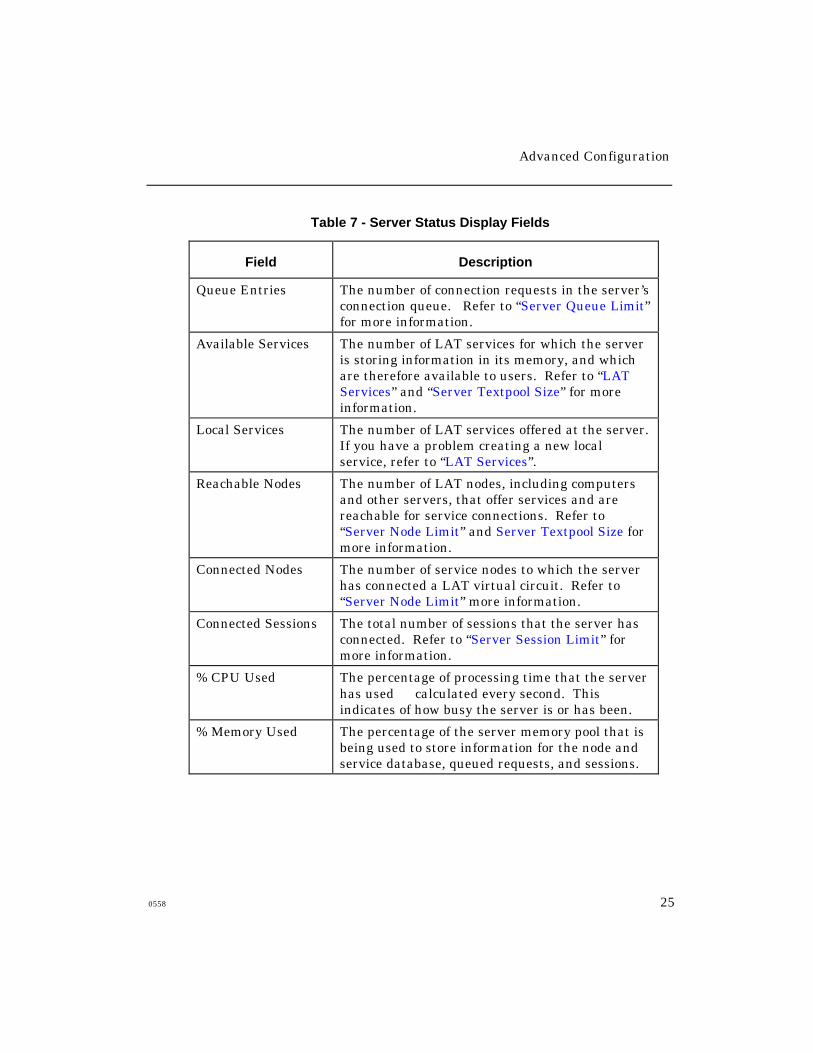
Show/Monitor Server Status
This display indicates how well the server is operating under the current
load and can be helpful in identifying network or port problems. Table 7
describes the important fields:
Advanced Configuration
0558 25
Table 7 - Server Status Display Fields
Field Description
Queue Entries The number of connection requests in the server’sconnection queue. Refer to “Server Queue Limit”for more information.
Available Services The number of LAT services for which the serveris storing information in its memory, and whichare therefore available to users. Refer to “LATServices” and “Server Textpool Size” for moreinformation.
Local Services The number of LAT services offered at the server.If you have a problem creating a new localservice, refer to “LAT Services”.
Reachable Nodes The number of LAT nodes, including computersand other servers, that offer services and arereachable for service connections. Refer to“Server Node Limit” and Server Textpool Size formore information.
Connected Nodes The number of service nodes to which the serverhas connected a LAT virtual circuit. Refer to“Server Node Limit” more information.
Connected Sessions The total number of sessions that the server hasconnected. Refer to “Server Session Limit” formore information.
% CPU Used The percentage of processing time that the serverhas used calculated every second. Thisindicates of how busy the server is or has been.
% Memory Used The percentage of the server memory pool that isbeing used to store information for the node andservice database, queued requests, and sessions.
Advanced Configuration
26 0558
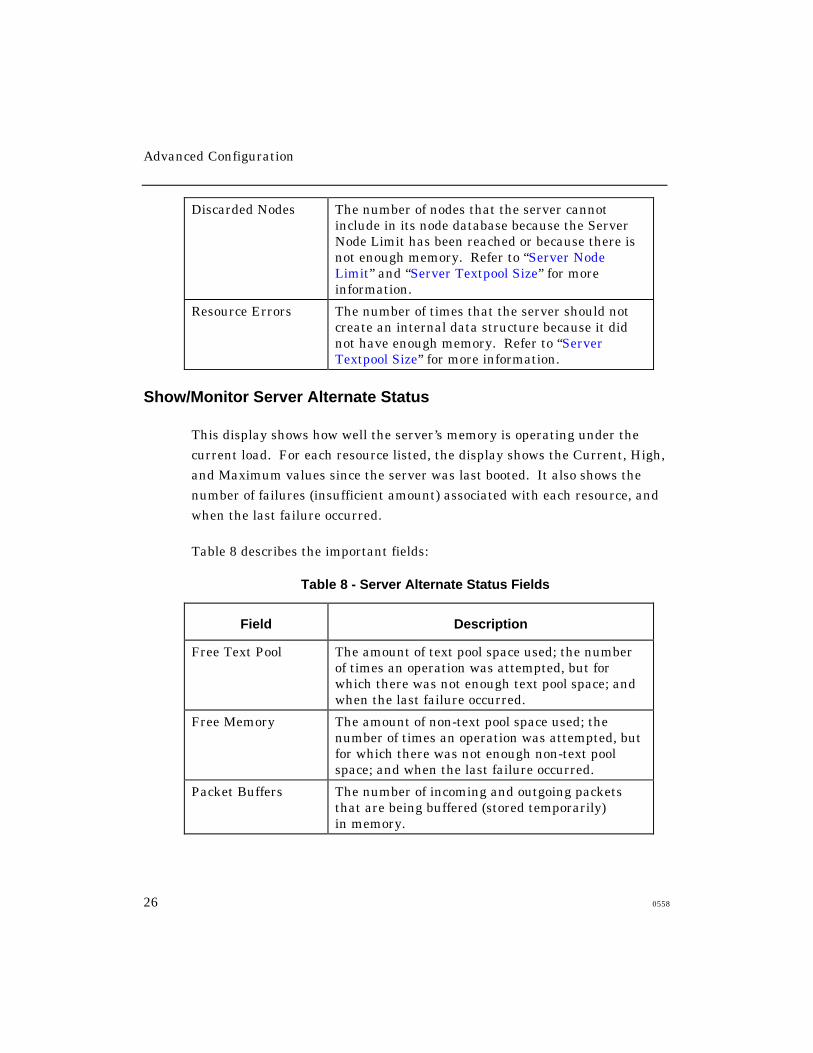
Discarded Nodes The number of nodes that the server cannotinclude in its node database because the ServerNode Limit has been reached or because there isnot enough memory. Refer to “Server NodeLimit” and “Server Textpool Size” for moreinformation.
Resource Errors The number of times that the server should notcreate an internal data structure because it didnot have enough memory. Refer to “ServerTextpool Size” for more information.
Show/Monitor Server Alternate Status
This display shows how well the server’s memory is operating under the
current load. For each resource listed, the display shows the Current, High,
and Maximum values since the server was last booted. It also shows the
number of failures (insufficient amount) associated with each resource, and
when the last failure occurred.
Table 8 describes the important fields:
Table 8 - Server Alternate Status Fields
Field Description
Free Text Pool The amount of text pool space used; the numberof times an operation was attempted, but forwhich there was not enough text pool space; andwhen the last failure occurred.
Free Memory The amount of non-text pool space used; thenumber of times an operation was attempted, butfor which there was not enough non-text poolspace; and when the last failure occurred.
Packet Buffers The number of incoming and outgoing packetsthat are being buffered (stored temporarily)in memory.
Advanced Configuration
0558 27
Using TCP/IP Features
Xyplex Access Servers support connections to TCP/IP nodes. They also
support several Internet protocols and features. This section describes how
to configure a server’s Internet-related settings and enable Telnet features.
It covers these topics:
• Defining Basic Internet Settings
• Configuring Internet Routes
• IP and IPX Traffic Filtering1
• IPX RIP and SAP Import/Export Filters
• Configuring Rotary Connections
• Configuring RLOGIN support
• Remote Management Support
• Loading through Internet Protocols
• Configuring the Access Server as a Domain Name Server
• Using IP Reassembly
• Using TCP Resequencing
1 Although IPX RIP and SAP filtering is not related to TCP/IP, it is included in this
section so that all routing protocol filters can be covered in a single section.

Advanced Configuration
28 0558
Configuring IP Routes
Large networks with many hosts and servers are often divided into smaller,
separate networks. These subnetworks, or “subnets,” can exist in the same
or separate locations. Sites with a small number of devices, which are
connected through routers to larger IP networks (e.g., the Internet), can
also be divided into subnets.
The Internet protocol supports communication between devices on
separate networks and subnets through gateways (or routers). An IP
route specifies the preferred router for routing data traffic to a remote
network or subnet. The server maintains a table of IP routes, called the
“IP route table,” in both its operational and permanent databases.
Figure 1. IP Route
Advanced Configuration
0558 29
Host and Network Routes
There are two types of IP route table entry: host entries and network
entries. Each specifies a gateway to use. When the server attempts to
communicate with an Internet node, it compares the node’s IP address
and subnet mask with its own address and mask, to determine whether
the node resides on the same network. If it does, the server sends the
data traffic directly to the node.
If the node does not reside on the same network, the server searches its IP
route table to find a matching host entry. If it finds a match, the server
sends the data traffic to the gateway indicated in the table. The gateway
forwards the traffic to the destination. If the server does not find a
matching host entry, it looks for a matching network entry.
If it still does not find a match, the server sends the traffic to the primary or
secondary gateway.

Advanced Configuration
30 0558
Dynamic Routing
IP routers communicate among themselves, forwarding network traffic to
each other and between networks, using routing protocols such as the
Routing Information Protocol (RIP). The routers also select the most
efficient path to remote networks; this is called “dynamic routing.”
As conditions change, the path to a remote network might change. When
this happens, the access server is informed through routing messages that
the packets it has sent to a particular router were forwarded to a different
router on the same network. This ensures that the packets eventually
reach the destination. IP routes that the server obtains in this way are
called “learned” routes.
NOTE: Xyplex Access Servers “listen” to routing protocol messages when
the routed daemon is enabled; however, they do not actively
participate in the protocols.
Static Routing
For some networks with multiple routers, dynamic routing might not be
enabled or available. At these sites, the access server must select a specific
router to insure that packets are forwarded to the right destination. To do
this, the host or server manager specifies database entries that map specific
destination networks or hosts to specific routers. This is called “static
routing.” Static IP routes are also called “locally specified IP routes.”
The access server can store both dynamic and static IP routes. The
software prevents duplicate entries (entries where the destination address
and subnet mask match an existing entry).
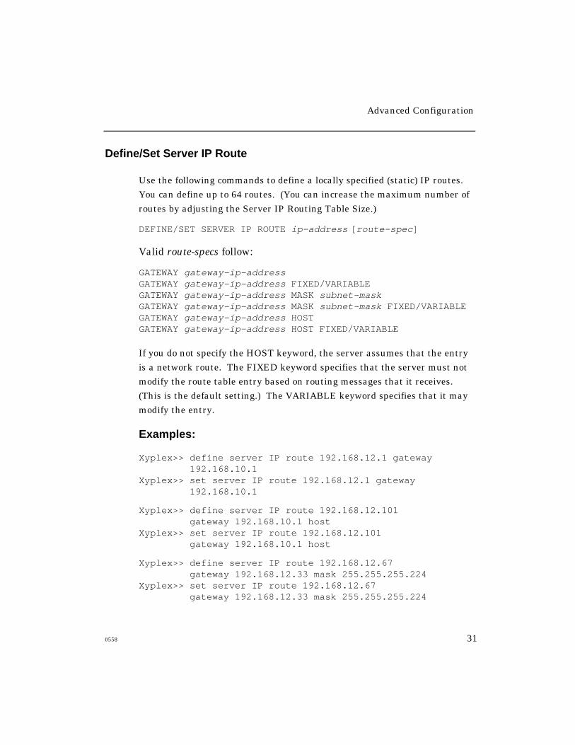
Advanced Configuration
0558 31
Define/Set Server IP Route
Use the following commands to define a locally specified (static) IP routes.
You can define up to 64 routes. (You can increase the maximum number of
routes by adjusting the Server IP Routing Table Size.)
DEFINE/SET SERVER IP ROUTE ip-address [route-spec]
Valid route-specs follow:
GATEWAY gateway-ip-addressGATEWAY gateway-ip-address FIXED/VARIABLEGATEWAY gateway-ip-address MASK subnet-maskGATEWAY gateway-ip-address MASK subnet-mask FIXED/VARIABLEGATEWAY gateway-ip-address HOSTGATEWAY gateway-ip-address HOST FIXED/VARIABLE
If you do not specify the HOST keyword, the server assumes that the entry
is a network route. The FIXED keyword specifies that the server must not
modify the route table entry based on routing messages that it receives.
(This is the default setting.) The VARIABLE keyword specifies that it may
modify the entry.
Examples:
Xyplex>> define server IP route 192.168.12.1 gateway192.168.10.1
Xyplex>> set server IP route 192.168.12.1 gateway192.168.10.1
Xyplex>> define server IP route 192.168.12.101gateway 192.168.10.1 host
Xyplex>> set server IP route 192.168.12.101gateway 192.168.10.1 host
Xyplex>> define server IP route 192.168.12.67gateway 192.168.12.33 mask 255.255.255.224
Xyplex>> set server IP route 192.168.12.67gateway 192.168.12.33 mask 255.255.255.224

Advanced Configuration
32 0558
Clear/Purge Server IP Route
Use these commands to remove a static IP route from the
server’s databases:
CLEAR/PURGE SERVER IP ROUTE entry
CLEAR/PURGE SERVER IP ROUTE ALL
An entry refers to the entry number that corresponds to the route in the
List/Show/Monitor Server IP Routes display. (See Figure 2.)
Show/List/Monitor Server IP Route
Use these commands to view all currently available IP routes. Figure 2
shows a sample display:
Xyplex> SHOW SERVER IP ROUTE ALL
Address Gateway Mask Last Modified
1 192.168.10.101 192.168.11.1 255.255.255.0 NET/FIXED 21 Mar 1996 09:22
2 192.168.11.101 192.168.11.2 0.0.0.0 HOST/VAR 21 Mar 1996 09:22
Figure 2 - Server IP Routes Display
Advanced Configuration
0558 33
IP Traffic Filtering
IP traffic filters determine which IP sources and destinations can
communicate with each other through the access server’s ports. You can set
up these filters on the LAN interface or on individual ports. You define
filters on a per-port basis when users/clients gain access to the server
through a network protocol, such as SLIP or PPP.
The access server applies the filters to IP packets as it receives them from
the attached LAN or specified port(s).
A traffic filter specifically allows or restricts traffic between two points;
for example, between a dial-in client and a network host. Traffic filters
also determine which IP protocols the access server may forward, and can
allow or restrict communication through specific TCP and UDP ports.
Additionally, IP traffic filters can allow or restrict the forwarding of
TCP packets when the packet’s SYN bit is set to ON and the ACK bit is
set to OFF. This bit pattern indicates that the sender is trying to open
a new session with a destination port. By discarding packets with this
bit pattern, you prevent remote users from opening sessions with hosts
on the local network.
Advanced Configuration
34 0558
Enabling IP Filtering
By default, IP traffic filtering is disabled. Use this command to enable it, or
to disable it later:
DEFINE SERVER IP FILTERING [ENABLED]
[DISABLED]
IP Traffic Filter Criteria
You can specify the following criteria in an IP traffic filter:
• IP protocol type: specific protocol ID number, TCP, UDP,
or ALL
• Destination IP address and subnet mask
• Destination port number or range of numbers
• Source port number or range of numbers
• Source IP address and subnet mask
• Whether a TCP packet has its SYN bit ON and its ACK bit OFF
Advanced Configuration
0558 35
Determining the Most Specific Filter
When an inbound IP packet is neither TCP nor UDP, the server ignores any
filters that specify an individual TCP or UDP port, or range of ports. If it
receives a packet that has multiple matching filters, the server applies the
most specific filter. The server uses the following process to determine the
most specific filter:
1. The server first looks for matching filters that specify an IP protocol
type (including type ALL). If one or more filters meet this condition,
the server ignores filters that do not specify an IP protocol type. If
only one matching filter specifies an IP protocol type, the server
applies that filter.
2. If more than one matching filter specifies an IP protocol type, the server
looks for filters that match the range of destination TCP or UDP ports
(i.e., the range that the TCP or UDP port falls within). If multiple
filters specify an equal range of port numbers, the server looks for filters
with the lowest beginning port number. If only one matching filter
specifies the narrowest range of destination TCP or UDP ports, the
server applies that filter.
3. If more than one of the remaining filters specify the narrowest
destination TCP/UDP port range, the server looks for filters that specify
a TCP SYN value (ON or OFF). If only one filter specifies a TCP SYN
value, the server applies that filter.
4. If more than one of the remaining filters specify a TCP SYN value, the
server looks for filters that specify the range of source TCP or UDP
ports. When multiple filters specify an equal range of port numbers,
the server looks for filters with the lowest beginning port number. If
only one matching filter specifies the narrowest range of source
TCP/UDP ports, the server applies that filter.
Advanced Configuration
36 0558
5. If more than one of the remaining filters specify the narrowest range of
source TCP or UDP ports, the server looks for matching filters that
specify the destination IP subnet. If only one filter specifies the largest
destination IP subnet mask, the server applies that filter.
6. If more than one of the remaining filters specify the largest destination
IP subnet mask, the server looks for matching filters that specify the
source IP subnet. At this point only one filter should remain; the server
applies that filter.
Traffic Filter Commands
Use the following commands to define IP traffic filters. Note that the
Define/Set Server commands affect packets that the server receives from
the attached LAN. Define/Set Port commands affect packets received
through individual ports.
DEFINE/SET SERVER IP FILTER criteria instructions
DEFINE/SET PORT port-list IP FILTER criteria instructions
Valid criteria follow:
PROTOCOL [protocol-id] (0-to-255)[TCP]
[UDP]
[ALL]
DESTINATION PORT [port-number] (0-to-65535)[port-number - port-number] (0-to-65535 - 0-to-65535)[ALL]
SYN [ON]
[ALL]
Advanced Configuration
0558 37
SOURCE PORT [port-number] (0-to-65535)[port-number - port-number] (0-to-65535 - 0-to-65535)[ALL]
DESTINATION [ip-address [MASK subnet-mask]]
[ALL]
SOURCE [ip-address [MASK subnet-mask]]
[ALL]
Valid filter-instructions follow:
DISCARD
FORWARD
Protocol
The TCP or UDP Protocol ID number.
SYN ON/ALL
SYN ON means that the SYN (synchronization) bit is set to ON and the
ACK (acknowledge) bit is set to OFF in the TCP header. SYN ALL
represents any value for the SYN and ACK bits.
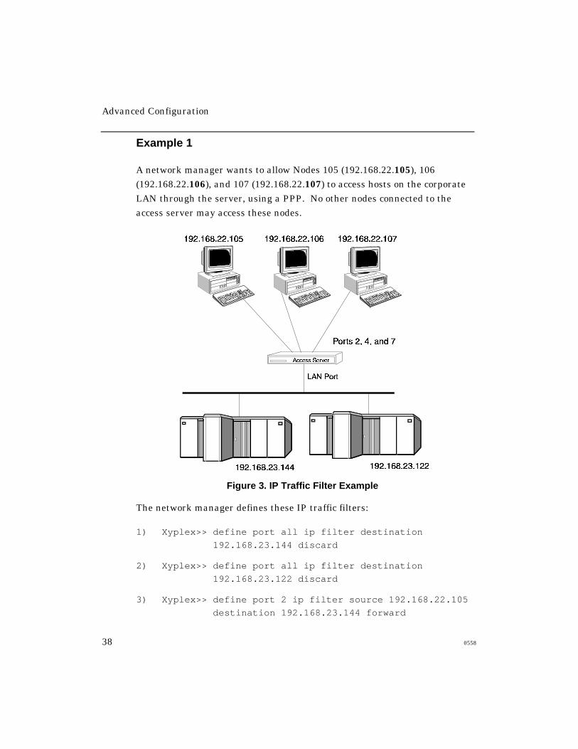
Advanced Configuration
38 0558
Example 1
A network manager wants to allow Nodes 105 (192.168.22.105), 106
(192.168.22.106), and 107 (192.168.22.107) to access hosts on the corporate
LAN through the server, using a PPP. No other nodes connected to the
access server may access these nodes.
Figure 3. IP Traffic Filter Example
The network manager defines these IP traffic filters:
1) Xyplex>> define port all ip filter destination
192.168.23.144 discard
2) Xyplex>> define port all ip filter destination
192.168.23.122 discard
3) Xyplex>> define port 2 ip filter source 192.168.22.105
destination 192.168.23.144 forward
Advanced Configuration
0558 39
4) Xyplex>> define port 2 ip filter source 192.168.22.105
destination 192.168.23.122 forward
5) Xyplex>> define port 4 ip filter source 192.168.22.106
destination 192.168.23.144 forward
6) Xyplex>> define port 4 ip filter source 192.168.22.106
destination 192.168.23.122 forward
7) Xyplex>> define port 7 ip filter source 192.168.22.107
destination 192.168.23.144 forward
8) Xyplex>> define port 7 ip filter source 192.168.22.107
destination 192.168.23.122 forward
Because Filters 3 - 8 specify source IP addresses, they are more specific
than Filters 1 and 2, which only specify destinations. Therefore, Filters 3 -
8 override Filters 1 and 2.
Example 2
This example builds upon the scenario described in the previous example.
Now, the network manager wants to deny Telnet access to the hosts on the
corporate LAN. The TCP port number for Telnet is 23. The network
manager defines these filters:
Xyplex>> define port 2,4,7 ip filter dest port 23 dest
192.168.23.122 discard
Xyplex>> define port 2,4,7 ip filter dest port 23 dest
192.168.23.144 discard
Because these filters specify a TCP port number, they are more specific than
the source/destination filters defined in Example 1. Therefore, they override
the action of the filter defined in Example 1. As a result, the nodes
connected to Ports 2, 4, and 7 cannot access the hosts through Telnet, but
can still access them through other IP protocols.
Advanced Configuration
40 0558
Example 3
This example builds upon the scenarios described in the previous examples.
Now, the network manager wants to prevent the nodes connected to Ports
2, 4, and 7 from sharing files with the hosts on the corporate LAN through
UDP Network File Sharing (NFS). To do this, the network manager
prevents UDP broadcasts with this filter:
Xyplex>> define port 2,4,7 ip filter protocol udp discard
Because this filter specifies a protocol, it is more specific than the filters
defined in the previous examples. Therefore, it overrides the filters defined
in the previous examples.
IPX Traffic Filters
NOTE: Although IPX Traffic Filtering is not a TCP/IP feature, it is
described here so that all routing protocol filters can be covered in
a single section.
IPX traffic filters determine which IPX sources and destinations may
communicate with each other through the access server’s ports. A traffic
filter specifically allows or restricts traffic between two points; for example,
between two networks or between a NetWare client and server.
You configure traffic filters on a server and/or individual port basis. The
server applies them to packets as it receives them.
Traffic Filter Criteria
You can specify the following criteria in a traffic filter:
• Destination IPX network and/or Ethernet address
• Source IPX network and/or Ethernet address
Advanced Configuration
0558 41
Determining the Most Specific Filter
When the server receives an IPX packet that meets the criteria of more
than one traffic filter, it applies the most specific filter. The server uses
the following process to determine which traffic filter is most specific:
1. The server looks for filters that specify a matching destination IPX
network. If one or more matching filters meet this condition, the server
ignores any filters that do not. If only one of the remaining filters
specifies a matching destination network, the server applies that filter.
2. If more than one filter specifies a matching destination network, theserver looks for filters that specify a matching destination Ethernet
address. If one or more matching filters meet this condition, the
server ignores any filters that do not. If only one of the remaining
filters specifies a matching destination address, the server applies that
filter.
3. If more than one of the remaining filters specify a matching destination
address or if no filters do the server looks for filters that specify amatching source IPX network. If one or more matching filters meet this
condition, the server ignores any filters that do not. If only one of the
remaining filters specifies a matching source network, the server
applies that filter.
4. If more than one of the remaining filters specify a matching source
network or if no filters do the server looks for a filter that specifiesa matching source Ethernet address. At this point only one filter
should remain; the server applies that filter.
Advanced Configuration
42 0558
Traffic Filter Commands
By default, IPX traffic filtering is disabled. Use this command to enable it,
or to disable it later:
DEFINE SERVER IPX FILTERING [ENABLED]
[DISABLED]
Use these commands to define IPX traffic filters:
DEFINE SERVER IPX FILTER destination-criteria [FORWARD]
[DISCARD]
DEFINE SERVER IPX FILTER source-criteria [FORWARD]
[DISCARD]
DEFINE SERVER IPX FILTER dest-criteria source-criteria [FORWARD]
[DISCARD]
DEFINE PORT port-list IPX FILTER destination-criteria [FORWARD]
[DISCARD]
DEFINE PORT port-list IPX FILTER source-criteria [FORWARD]
[DISCARD]
DEFINE PORT port-list IPX FILTER dest-criteria source-criteria
[FORWARD]
[DISCARD]
The destination-criteria can include:
DESTINATION NETWORK [ipx-network]
[ALL]
DESTINATION NODE [node-address] (e.g., 08008712AB34)[ALL]
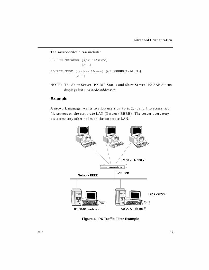
Advanced Configuration
0558 43
The source-criteria can include:
SOURCE NETWORK [ipx-network]
[ALL]
SOURCE NODE [node-address] (e.g., 08008712ABCD)[ALL]
NOTE: The Show Server IPX RIP Status and Show Server IPX SAP Status
displays list IPX node-addresses.
Example
A network manager wants to allow users on Ports 2, 4, and 7 to access two
file servers on the corporate LAN (Network BBBB). The server users may
not access any other nodes on the corporate LAN.
Figure 4. IPX Traffic Filter Example
Advanced Configuration
44 0558
First, the network manager defines a traffic filter that discards all traffic to
the corporate LAN by default:
Xyplex>> define port all ipx filter dest network bbbb
discard
Next, the network manager defines filters that allow users at Ports 2, 4, and
7 to forward traffic to the two file servers on Network BBBB:
Xyplex>> define port 2,4,7 ipx filter dest node
000001aabbcc forward
Xyplex>> define port 2,4,7 ipx filter dest node
000001ddeeff forward
Because these filters are more specific than the previously defined filter, the
server applies them, and consequently allows traffic to be forwarded to the
two destination addresses.
IPX-RIP Import/Export Filters
By default, when the IPX protocol is enabled, a Xyplex Access Server adds
all routes that it learns through RIP to its IPX route table. This process is
called importing. The server also advertises all routes in its IPX route table
to other IPX routers, by default. This process is called exporting.
You can define filters that prevent the server from importing or exporting
routes. You can define these filters on a server-wide basis or on an
individual port basis. Import filter rules specify whether routes learned
through RIP are “accepted” or “discarded.” Export filter rules specify
whether routes in the route table are “advertised” or “hidden.” You can
apply filters to specific networks or to ranges of networks.
NOTE: If an IPX service advertisement (SAP table entry) is
associated with a filtered RIP packet, the filter rule is also
applied to the SAP table entry.

Advanced Configuration
0558 45
When There Are Multiple Matching Filters
When checking its RIP filter database, the server might find more than one
matching filter. When this happens, the server applies the most specific
filter. A filter that specifies an actual network is considered more specific
than one that specifies Network ALL.
Defining RIP Filters
By default, IPX filtering is disabled. Use this command to enable it, or to
disable it later:
DEFINE SERVER IPX FILTERING [ENABLED]
[DISABLED]
IPX-RIP Export Filters
Use the following commands to define IPX-RIP export filters. Note that
using the SERVER keyword affects routes that the server learns through
the attached LAN. The PORT keyword affects routes that the server learns
through a specified port.
DEFINE/SET SERVER IPX RIP EXPORT NETWORK [network] [ADVERTISE]
[ALL] [HIDE]
DEFINE/SET PORT port-list IPX RIP EXPORT NETWORK [network] [ADVERTISE]
[ALL] [HIDE]
A network is a hexadecimal value from 1 to FFFFFFFE. Use these
commands to remove RIP export filters:
CLEAR/PURGE SERVER IPX RIP EXPORT [ALL]
[NETWORK [network]]
[ALL]
CLEAR/PURGE PORT port-list IPX RIP EXPORT [ALL]
[NETWORK [network]]
[ALL]
Advanced Configuration
46 0558
Examples
Xyplex>> define server ipx rip export network all hide
Xyplex>> define port all ipx rip export network all hide
Xyplex>> define server ipx rip export network 1234
advertise
Xyplex>> define port all ipx rip export network 1234
advertise
Xyplex>> purge server ipx rip export all
Xyplex>> purge server ipx rip export network network 1234
Xyplex>> purge port all ipx rip export network 1234
RIP Import Filters
Use the following commands to define RIP import filters. Note that using
the SERVER keyword affects routes that the server learns through the
attached LAN. The PORT keyword affects routes that the server learns
through a specified port.
DEFINE SERVER IPX RIP IMPORT NETWORK [network] [ACCEPT]
[ALL] [DISCARD]
DEFINE PORT port-list IPX RIP IMPORT NETWORK [network] [ACCEPT]
[ALL] [DISCARD]
A network is a hexadecimal value from 1 to FFFFFFFE. Use these
commands to remove RIP import filters:
CLEAR/PURGE SERVER IPX RIP IMPORT [ALL]
[NETWORK [network]]
[ALL]
CLEAR/PURGE PORT port-list IPX RIP IMPORT [ALL]
[NETWORK [network]]
[ALL]
Advanced Configuration
0558 47
Examples
Xyplex>> define server ipx rip import network all discard
Xyplex>> define port all ipx rip import network all discard
Xyplex>> define server ipx rip import network 1234 accept
Xyplex>> define port all ipx rip import network 1234 accept
Xyplex>> purge server ipx rip import network all
Xyplex>> purge port all ipx rip import all
Xyplex>> purge server ipx rip import network 1234
Xyplex>> purge port all ipx rip import network 1234
SAP Import/Export Filters
By default, when the IPX protocol is enabled, a Xyplex Access Server adds
all service “Names” and “Types” that it learns through the Service
Advertisement Protocol (SAP) to its IPX SAP table. This process is called
importing. The server also advertises all service Names and Types in its
SAP table to other IPX routers, by default. This process is called exporting.
You can define filters that prevent the server from importing or exporting
service Names and Types. Import filter rules specify whether service
Names and Types learned through SAP are “accepted” or “discarded.”
Export filter rules specify whether service Names and Types are
“advertised” or “hidden.” You can apply SAP filters to specific networks or
to ranges of networks.
NOTE: If a service advertisement (SAP) is associated with a filtered RIP
packet, the server applies the filter rule to the SAP also.
SAP Filter Criteria
SAP filters identify services through one or more of these criteria:
• Network the source or destination network
• Type The NetWare service type; e.g., File Server, Printer
The SHOW IPX SAP Display shows the Network and Type information
associated with each SAP in the server’s database.

Advanced Configuration
48 0558
When There Are Multiple Matching Filters
When checking its SAP filter database, the server might find multiple
matching filters. When this happens, the server uses the following rules to
determine which filter to apply:
1. Only consider filters that indicate a specific network.
2. If multiple matching filters still exist, only consider the filter(s) that
indicate a specific Type.
3. At this point only one filter remains. The server applies its rule.
Defining SAP Filters
By default, IPX filtering is disabled. Use this command to enable it, or to
disable it later:
DEFINE SERVER IPX FILTERING [ENABLED]
[DISABLED]
SAP Export Filters
Use the following commands to define SAP export filters. Note that using
the SERVER keyword affects services that the server learns through the
attached LAN. The PORT keyword affects services that the server learns
through a specified port.
DEFINE/SET SERVER IPX SAP EXPORT sap-characteristics [ADVERTISE]
[HIDE]
DEFINE/SET PORT port-list IPX SAP EXPORT sap-characteristics [ADVERTISE]
[HIDE]
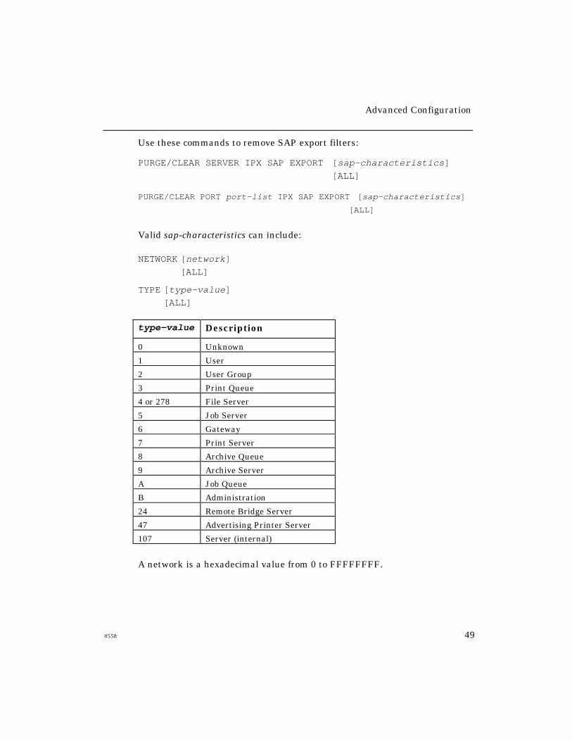
Advanced Configuration
0558 49
Use these commands to remove SAP export filters:
PURGE/CLEAR SERVER IPX SAP EXPORT [sap-characteristics]
[ALL]
PURGE/CLEAR PORT port-list IPX SAP EXPORT [sap-characteristics]
[ALL]
Valid sap-characteristics can include:
NETWORK [network]
[ALL]
TYPE [type-value]
[ALL]
type-value Description
0 Unknown
1 User
2 User Group
3 Print Queue
4 or 278 File Server
5 Job Server
6 Gateway
7 Print Server
8 Archive Queue
9 Archive Server
A Job Queue
B Administration
24 Remote Bridge Server
47 Advertising Printer Server
107 Server (internal)
A network is a hexadecimal value from 0 to FFFFFFFF.

Advanced Configuration
50 0558
Examples
Xyplex>> define server ipx sap export network all hide
Xyplex>> define port all ipx sap export network all hide
Xyplex>> define server ipx sap export network 1234 type 6advertise
Xyplex>> define port all ipx sap export network 1234 type 6advertise
Xyplex>> purge server ipx sap export network all
SAP Import Filters
Use the following commands to define SAP import filters. Note that using
the SERVER keyword affects services that the server learns through the
attached LAN. The PORT keyword affects services that the server learns
through a specified port.
DEFINE SERVER IPX SAP IMPORT sap-characteristics [ACCEPT]
[DISCARD]
DEFINE PORT port-list IPX SAP IMPORT sap-characteristics [ACCEPT]
[DISCARD]
Use these commands to remove SAP import filters:
PURGE/CLEAR SERVER SAP IMPORT [sap-characteristics]
[ALL]
PURGE/CLEAR PORT port-list SAP IMPORT [sap-characteristics]
[ALL]

Advanced Configuration
0558 51
Examples
Xyplex>> define server ipx sap import network all discard
Xyplex>> define port all ipx sap import network all discard
Xyplex>> define server ipx sap import network 1234 type 4accept <allow file servers only>
Xyplex>> define port all ipx sap import network 1234 type 4accept <allow file servers only>
Xyplex>> purge server ipx sap import network all
Xyplex>> purge port all ipx sap import network all
Advanced Configuration
52 0558
Configuring Rotary Connections
The term “rotary” refers to the assignment of an IP address or domain
name to multiple destinations that offer the same type of service. When
a user attempts to connect to the IP address or domain name, the server
connects him to an available port that has been assigned that address or
domain name. (See Figure 5.)
The access server supports two rotary connection types:
• Assigning an IP address to a group of ports on a server
• Assigning a single domain name to several ports or groups of ports,
which can be on multiple servers
You can use these methods together or separately. For example, while a
given IP address for a group of ports can only be used at a single server, you
can assign many IP addresses to the same domain name. Generally, this
requires that you have a domain name server that returns multiple IP
addresses for a single name. Figure 5 shows both of these applications.
The rotary is transparent to users. A user simply requests a connection to a
destination domain name or IP address, and the server sets up the
connection with one of the available ports in the rotary group.

Advanced Configuration
0558 53
Figure 5. Rotary Connections
When a user tries to connect to a rotary that is configured on one or more
other Xyplex servers, the servers set up the connection on the least recently
used server in the rotary group. When connecting to a rotary through a
domain name, the server tries to connect to the least recently tried IP
address for that domain.
If the user has Autoconnect enabled, the server tries each available IP
address until it makes a connection. Otherwise, the server only attempts
to connect to the next IP address associated with the domain name entry.
Advanced Configuration
54 0558
When a user on a non-Xyplex unit, such as a UNIX host, tries to make a
connection to the rotary through a domain name, the unit makes the
connection based on its own rules. UNIX implementations vary. Some
hosts only attempt to connect to the first IP address associated with the
domain name. Others go down the list in order.
Configuring the Rotary
Use the following commands to set up a rotary. By default, the server’s IP
address is mapped to all ports (Port 0 - Port n).
DEFINE/SET SERVER IP ROTARY ip-address port-list
DEFINE/SET SERVER IP ROTARY domain-name port-list
The following sections explain how to set up rotaries for
sample applications.
Simple Rotary on a Single Server
Users can connect to this type of rotary through either an IP address or
domain name. To connect eight server ports to a host that is not connected
to the Ethernet network, use this command:
Xyplex>> define server IP rotary 192.168.11.10 1-8
Xyplex>> define port 1-8 telnet remote 23
The server’s address, 192.168.11.10, can only be used at a single server,
even if ports at another server physically connect to the same device or offer
the same type of service.
Advanced Configuration
0558 55
Connections to the Rotary through a Domain Name
To enable users to connect to the rotary through a domain name, you must
map the domain name to the appropriate IP address in the host name tables
at your domain name server (e.g., \etc\hosts).
If you are using a Xyplex server to resolve domain names (map them to IP
addresses), add a locally defined domain name to that server’s domain
name database. For example, to assign the domain name
“host.xyplex.com” to a rotary that has the IP address 192.168.11.10, you
would use these commands:
Xyplex>> define domain host.xyplex.com 192.168.11.10
Xyplex>> set domain host.xyplex.com 192.168.11.10
Rotary on Multiple Servers
Configuring a rotary that is located on two or more servers is similar to
configuring a single-server rotary. You assign an IP address, which is
unique among all devices on the network, to the ports on each server in the
rotary. You then define a single domain name that maps to all of these IP
addresses. (When using an access server to resolve domain names, the
domain name can map to a maximum of 16 IP addresses.)
Searching for Available IP Rotary Ports
This feature manipulates the chain of sessions so that the disconnected
session is put back into its original place and not at the end of the list (if
Roundrobin is disabled). This means that when you search for available IP
ports the search always begins at the lowest port in the Rotary list.
Use the following command (in privileged mode) to search for the lowest
available IP port:
DEFINE SERVER ROTARY ROUNDROBIN [ENABLED/DISABLED]
Advanced Configuration
56 0558
The default is Roundrobin enabled. With Roundrobin disabled, the search
for an available port mapped to an IP Rotary will always begin at the first
port in the Rotary list. Use the following command to display which search
method is in use:
SHOW SERVER IP ROTARY
This screen displays one of the following search methods:
Round Robin search: ENABLED
or
Round Robin search: DISABLED, Search by first available
Domain Name Storage
To use the Rotary Connection feature, you must store domain names in a
database. When the server performs a domain name query (requests
information from the domain name server), it stores all answers for a
given domain name in its operational database. The software can store
multiple addresses for a domain name, in these ways:
• Multiple addresses in a single response from a domain
name server.
• Multiple addresses from different domain name servers (responses
to a broadcast domain name query) the server saves all answers.
• Multiple addresses can be defined in the server’s databases through
the Define/Set Domain commands.
The server can store up to 100 domain names. Each domain name is limited
to 16 IP address entries.
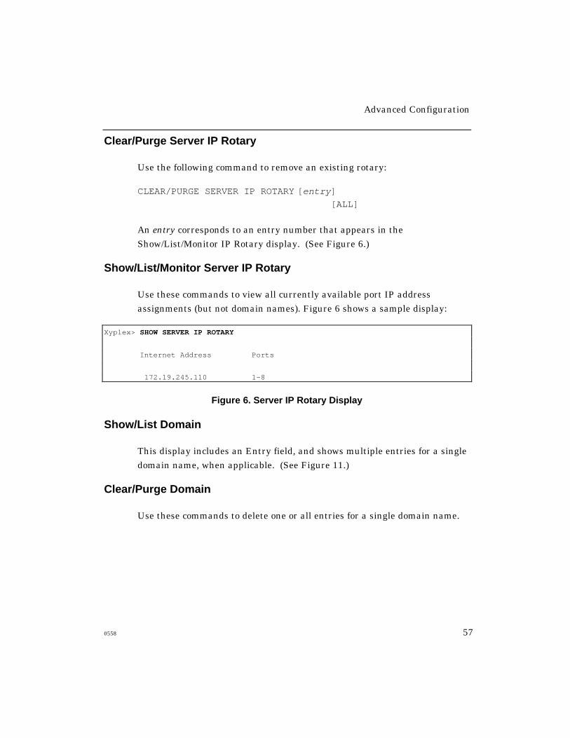
Advanced Configuration
0558 57
Clear/Purge Server IP Rotary
Use the following command to remove an existing rotary:
CLEAR/PURGE SERVER IP ROTARY [entry]
[ALL]
An entry corresponds to an entry number that appears in the
Show/List/Monitor IP Rotary display. (See Figure 6.)
Show/List/Monitor Server IP Rotary
Use these commands to view all currently available port IP address
assignments (but not domain names). Figure 6 shows a sample display:
Xyplex> SHOW SERVER IP ROTARY
Internet Address Ports
172.19.245.110 1-8
Figure 6. Server IP Rotary Display
Show/List Domain
This display includes an Entry field, and shows multiple entries for a single
domain name, when applicable. (See Figure 11.)
Clear/Purge Domain
Use these commands to delete one or all entries for a single domain name.
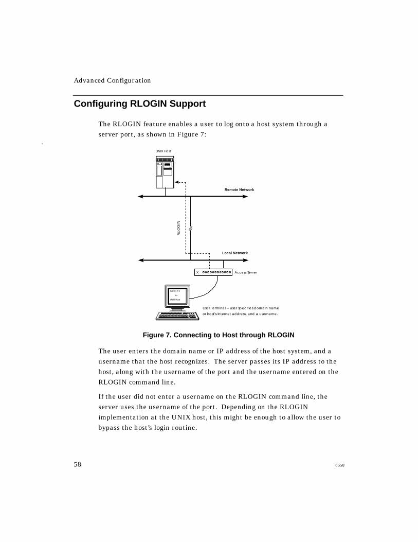
Advanced Configuration
58 0558
Configuring RLOGIN Support
The RLOGIN feature enables a user to log onto a host system through a
server port, as shown in Figure 7:
Local Network
X
Remote Network
RLO
GIN
User Terminal -- user specifies domain name
or host's Internet address, and a username.
Access Server
UNIX Host
Welcome
to
UNIX Host
Figure 7. Connecting to Host through RLOGIN
The user enters the domain name or IP address of the host system, and a
username that the host recognizes. The server passes its IP address to the
host, along with the username of the port and the username entered on the
RLOGIN command line.
If the user did not enter a username on the RLOGIN command line, the
server uses the username of the port. Depending on the RLOGIN
implementation at the UNIX host, this might be enough to allow the user to
bypass the host’s login routine.

Advanced Configuration
0558 59
Considerations
To set up the RLOGIN feature on the host, you modify certain files. For
example, on some UNIX hosts, you include an entry in the/etc/hosts.equiv file and, optionally, each user’s .rhosts file. Then,
when a user attempts to login to an account using RLOGIN and ausername that matches an entry in the etc/hosts.equiv file that user
is automatically logged on to the host. The user is not prompted for a
username and password.
The RLOGIN feature is enabled by default on the access server. You might
not want to use the RLOGIN feature with sensitive accounts, however,
since anyone who knows the right username can log on to the account. You
can disable RLOGIN through this command:
DEFINE SERVER RLOGIN DISABLED
Associated Commands
The access server supports RLOGIN through these commands:
DEFINE SERVER RLOGIN ENABLED/DISABLED
This command specifies whether users can make connections through
RLOGIN. The default is ENABLED.
RLOGIN
Log on to a host by specifying the host system and a username.
SHOW/MONITOR SESSION
View information about an RLOGIN session.
Advanced Configuration
60 0558
SHOW PORT x STATUS
Indicates “RLOGIN” in the Current Service field and “Port 513” in the
Current Port field when a port is being used for RLOGIN.
Defining RLOGIN Dedicated Services
NOTES: With dedicated RLOGIN service, you cannot specify adifferent username for RLOGIN. the only valid username isthe port’s username.
When you define a port for dedicated service the user will not beable to access the Xyplex prompt when disconnected from thepreferred host. When you define a port as preferred service theuser will see the prompt when disconnected.
DEFINE PORT port-list RLOGIN DEDICATED SERVICE service-name
Defining RLOGIN Preferred Services
Use this command to enable a preferred service using RLOGIN. Use the
SHOW PORT command to display the current preferred service setting for
the port
NOTES: With preferred RLOGIN service, you cannot specify a differentusername for RLOGIN. the only valid username is the port’susername.
When you define a port for dedicated service, the user will not beable to access the Xyplex prompt when disconnected from thepreferred host. When you define a port for preferred service theuser will see the prompt when disconnected.
SyntaxDEFINE PORT port-list RLOGIN PREFERRED SERVICE service-name
Advanced Configuration
0558 61
Defining RLOGIN Transparent Mode
Use this feature to enable the access server to complete a ZMODEM
transfer using the RLOGIN feature.
DEFINE/SET PORT [port-number] RLOGIN TRANSPARENT MODE
[ENABLED]
[DISABLED]
NOTE: Within an RLOGIN session, characters are passed raw (without
interpretation) and transparently. This allows the ZMODEM
transfer to complete.
ZModem Requirements
Feature Setting
Typeahead 1024
TCP Window Size 1024
Telnet CSI ESC Enabled
Telnet NEW LINE FILTER LF or Standard
Network Management
This section provides an overview of the access server’s network
management features. The software supports network management in
these ways:
• Simple Network Management Protocol (SNMP) support
• Telnet access to a server's console port
Advanced Configuration
62 0558
Using SNMP
This section explains how to use SNMP to manage Xyplex Access Servers. It
assumes that you plan to use an SNMP-based network management
software application, such as Xyplex ControlPoint™, to manage the
server(s). Hereafter, this section refers to your network management
application as a Network Operations Center (NOC).
SNMP is an Internet protocol, defined by RFC (Request for Comment) 1157,
that specifies how network management information is carried through a
network. The access server software implements an SNMP agent. The
server stores Management Information Base (MIB) data, and makes it
available when requested through SNMP.
The software supports standard and Xyplex-proprietary MIB objects. The
software agent accepts the GetRequest, GetNextRequest, and the
SetRequest functions and supports the following SNMP traps. These are
notices that can be sent to an SNMP client, indicating that a specific event
has occurred or the condition of a unit has changed.
Xyplex Access Servers can generate the following SNMP traps:
coldStart Signifies that the server is booting in a way that
indicates that its configuration might have been
changed. The access server generates this trap
immediately after
loading parameters.
authenticationFailure Signifies that the server is the addressee of an
improperly authenticated network protocol
message. SNMP community name and client
authentication failures cause the server to
generate this trap.

Advanced Configuration
0558 63
One trap is generated for each occurrence of its defined event. Note
that no traps are transmitted if the server has not been assigned an
IP address.
Figure 8 shows an example of SNMP in an extended network:
Figure 8. Network Management through SNMP
Advanced Configuration
64 0558
The server stores the following groups of MIB data:
System Describes the system as a whole.
Interfaces The network interfaces over which the system can send or
receive IP datagrams (messages).
Address Translation The Address Resolution Protocol (ARP)
table, which the server uses to match IP addresses to Ethernet
addresses.
IP The operation of the Internet Protocol.
ICMP The operation of the Internet Control Message Protocol.
TCP The operation of the Transmission Control Protocol.
UDP The operation of the IP User Datagram Protocol.
Obtaining/Importing the Supported MIBs
If you are using the Xyplex ControlPoint software, you do not need to
import any MIBs. The ControlPoint software package includes all of the
MIBs that you need.
If you are not using ControlPoint, you can use SNMP to manage all of the
access server’s settings provided that your NOC is capable of compiling
proprietary MIBs. The Xyplex-proprietary MIBs are available through the
Xyplex World Wide Web (WWW) server: http://www.xyplex.com.
In addition, a MIB kit is available from Xyplex, which contains all standard
and Xyplex-proprietary MIBs that Xyplex products support. The kit also
includes a text file that lists the MIB groups supported by the access
server’s SNMP agent, and provides useful information about how the agent
handles MIB objects.
Advanced Configuration
0558 65
To obtain the MIB kit, contact your Xyplex sales representative
or distributor.
Defining a Trap Client
An access server will not generate any SNMP Trap messages until you
define a Trap Client. A Trap Client is a specific NOC to which the access
server sends Trap messages. You can define one or more Trap Clients
through this command:
DEFINE/SET SERVER IP SNMP TRAP CLIENT [index] ip-address
An index value is a number from 1 to 4. The ip-address identifies the NOC
that should receive the Trap messages.
Example
Xyplex>> define server IP snmp trap client 1
172.18.12.3
Assigning SNMP Security Information (Optional)
By default, a Xyplex Bridge/Router accepts SNMP Get, Get_Next, and Set
requests from any NOC. You can restrict SNMP access to the bridge/router
by defining SNMP Clients and Communities. A Community refers to one or
more NOCs that specify the same Community string in their SNMP
messages. A Client is a specific NOC, which you identify through an IP or
Ethernet address.
NOTE: Intense use of GET_Next requests may degradeaccess server performance.
Advanced Configuration
66 0558
Table 9 shows how Get/Set Client and Community values determine which
NOCs can manage an access server.Table 9 - Get/Set Client and Community Settings
Get/Set
Client
Get/Set
Community
NOCs that Can Issue Get/Set Requests
None None Any
None Defined Any NOC that knows the Community value
Defined None NOCs defined as Clients
Defined Defined NOCs defined as Clients, which know theCommunity value
Get and Set Processing and Access Server Databases
SNMP GET processing reads the operational database. SNMP SETprocessing modifies both the operational and permanent databases. Ifthe unit is managed by SNMP, you may want to keep all ports Non-privileged or Secure. This reduces the possibility of the permanent andoperational databases becoming unsynchronized. In the case of tableswith a variable number of entries, such as local services or domainnames, this is particularly significant.
The port security table and the menu table are accessed by anindex number that may or may not point to the same data itemin the two databases.
Creating and Deleting Entries in SNMP Tables
Use the following guidelines to create and delete SNMP table entries:
• To create an SNMP entry:
Send an SNMP set request with a unique (non existent) objectId, and
the table status value set to valid.
Advanced Configuration
0558 67
The objectId contains the keys needed to create the table entry. No
other values are required to create the entry. Any additional values
needed are given defaults by the agent.
Any table item that is part of the Key is set read-only to prevent
conflicting entries. Most Keys in standard MIBs are read/write.
• To delete an SNMP entry:
Send an SNMP set request with the objectId of the table entry you want
to delete, and the table status entry set to invalid.
Defining Get and Set SNMP Clients
A Get Client is a specific NOC that is allowed to manage the access
server through Get and Get_Next requests. A Set Client is a NOC that
may issue Set requests to the access server. You can use the following
commands to define up to four of each of these client types:
DEFINE SERVER IP SNMP GET CLIENT [index] ip-address
DEFINE SERVER IP SNMP SET CLIENT [index] ip-address
An index value is a number from 1 to 4. Use the keyword NONE to delete a
previously defined Get or Set Client.
NOTE: Be sure to define Get and Set Client entries for your NOC before
you define any other Get or Set Clients.
Example
Xyplex>> define server IP snmp set client 1
172.18.121.3
Advanced Configuration
68 0558
Defining SNMP Communities
Get and Set Communities provide an additional level of security. If you do
not define any Get Clients, the access server will accept Get and Get_Next
requests from any NOC whose Get requests include a Community name
that matches the server’s Get Community. If you do not define a Get
Community, the access server will accept Get and Get_Next requests from
any NOC.
Similarly, if you do not define any Set Clients, the access server will accept
Set requests from any NOC whose requests include a Community name that
matches the server’s Set Community. If you do not define a Set
Community, the access server will accept Set requests from any NOC.
If you define a Trap Community, the access server will include the Trap
Community name in the Trap messages that it generates.
Use the following commands to define Get, Set, and Trap
Community names:
DEFINE SERVER IP SNMP GET COMMUNITY [“community-name”]
[NONE]
DEFINE SERVER IP SNMP SET COMMUNITY [“community-name”]
[NONE]
DEFINE SNMP TRAP COMMUNITY “community-name”
A community-name can include up to 23 characters. Do not include spaces.
Use the value NONE to delete a previously defined Get or Set Community.
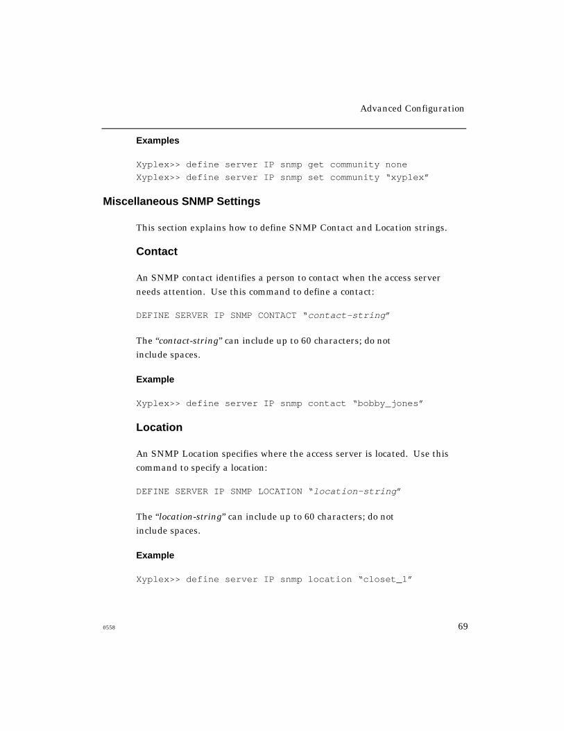
Advanced Configuration
0558 69
Examples
Xyplex>> define server IP snmp get community none
Xyplex>> define server IP snmp set community “xyplex”
Miscellaneous SNMP Settings
This section explains how to define SNMP Contact and Location strings.
Contact
An SNMP contact identifies a person to contact when the access server
needs attention. Use this command to define a contact:
DEFINE SERVER IP SNMP CONTACT “contact-string”
The “contact-string” can include up to 60 characters; do not
include spaces.
Example
Xyplex>> define server IP snmp contact “bobby_jones”
Location
An SNMP Location specifies where the access server is located. Use this
command to specify a location:
DEFINE SERVER IP SNMP LOCATION “location-string”
The “location-string” can include up to 60 characters; do not
include spaces.
Example
Xyplex>> define server IP snmp location “closet_1”
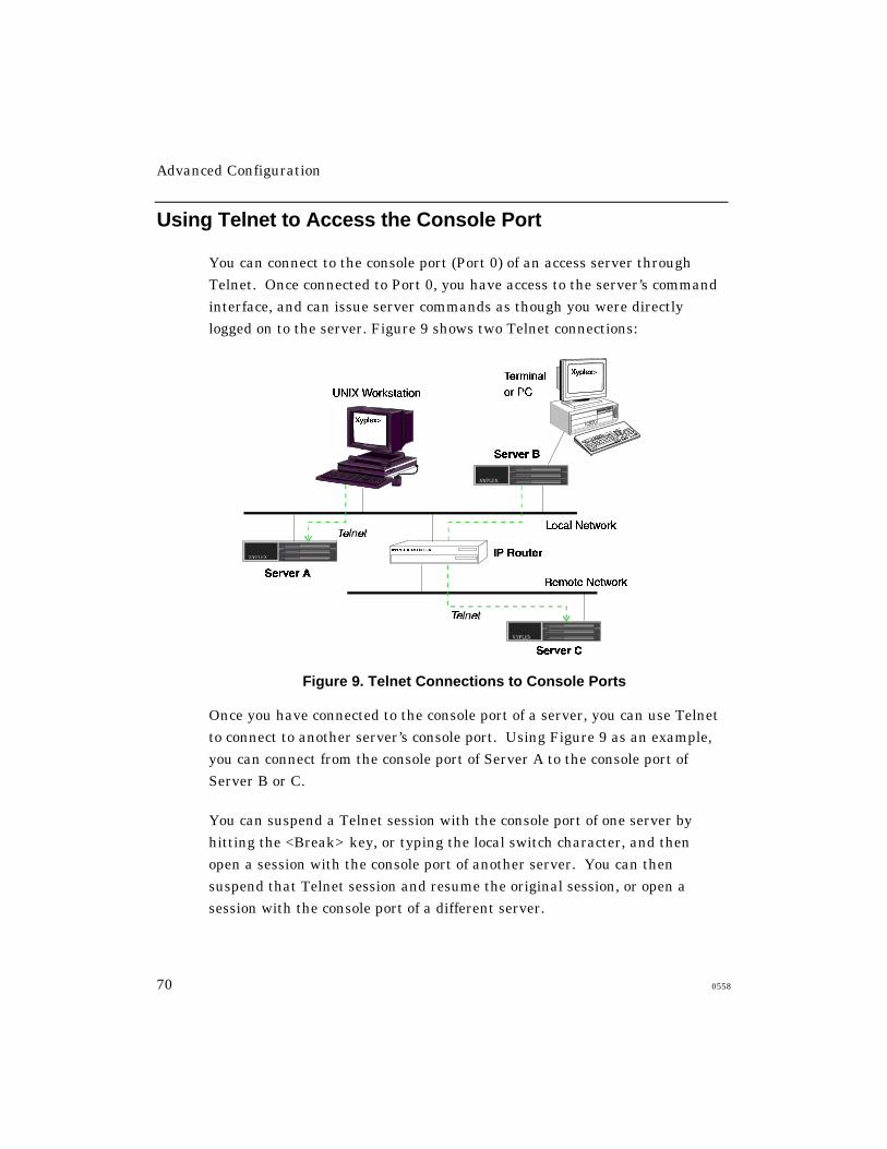
Advanced Configuration
70 0558
Using Telnet to Access the Console Port
You can connect to the console port (Port 0) of an access server through
Telnet. Once connected to Port 0, you have access to the server’s command
interface, and can issue server commands as though you were directly
logged on to the server. Figure 9 shows two Telnet connections:
Figure 9. Telnet Connections to Console Ports
Once you have connected to the console port of a server, you can use Telnet
to connect to another server’s console port. Using Figure 9 as an example,
you can connect from the console port of Server A to the console port of
Server B or C.
You can suspend a Telnet session with the console port of one server by
hitting the <Break> key, or typing the local switch character, and then
open a session with the console port of another server. You can then
suspend that Telnet session and resume the original session, or open a
session with the console port of a different server.

Advanced Configuration
0558 71
Telnet Console Command
Use these commands to access the console port (Port 0) of an access server
through Telnet:
TELNET CONSOLE ip-address
TELNET CONSOLE ip-address:telnet-port-number
TELNET CONSOLE domain-name
TELNET CONSOLE domain-name:telnet-port-number
Use the following command to access the console port from a UNIX host,
through Telnet. Note that you do not need to specify 2000 if you havepreviously issued the command DEFINE PORT 0 TELNET REMOTE 23.
TELNET [ip-address] 2000
[domain-name]
The following port settings are predefined for the access server’s console
port. You cannot change the values for these settings:
Characteristic Setting
ACCESS LOCALAUTOBAUD DISABLEDBREAK DISABLEDCHARACTER SIZE 8DEDICATED SERVICE NONEDIALUP DISABLEDDSRLOGOUT DISABLEDDTRWAIT DISABLEDFLOW CONTROL XONINPUT FLOW CONTROL ENABLEDINPUT SPEED 9600MODEM CONTROL DISABLEDOUTPUT FLOW CONTROL ENABLEDOUTPUT SPEED 9600PARITY NONESPEED 9600

Advanced Configuration
72 0558
Examples:
Xyplex> telnet console 192.168.2.30
Establish a session between this port and the console port of the Telnet
destination whose IP address is 192.168.2.30.
Xyplex> telnet console access1.xyplex.com
Establish a session between this port and the console port of the Telnet
destination whose domain name is access1.xyplex.com.
Define/Set Server Console Logout
Use the following command to specify whether the server should
immediately disconnect a console port session when a user logs out from the
port. This setting is enabled by default.
DEFINE/SET SERVER CONSOLE LOGOUT [ENABLED]
[DISABLED]
Loading through Internet Protocols
The access server supports three Internet protocols for loading software
and parameters:
• Bootstrap Protocol (BOOTP)
• Trivial File Transfer Protocol (TFTP) and Directed
TFTP (DTFTP)
• Reverse Address Resolution Protocol (RARP)
These network protocols enable the server to obtain load images
(software files) and parameter files from UNIX hosts and to use the
UNIX hosts as dump servers. Support for these protocols also enables
servers to receive load images and parameters, and to dump memory
contents, through an IP router.
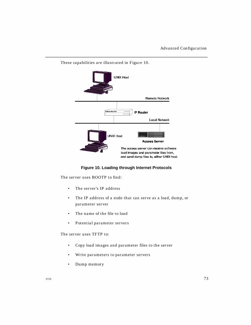
Advanced Configuration
0558 73
These capabilities are illustrated in Figure 10.
Figure 10. Loading through Internet Protocols
The server uses BOOTP to find:
• The server's IP address
• The IP address of a node that can serve as a load, dump, or
parameter server
• The name of the file to load
• Potential parameter servers
The server uses TFTP to:
• Copy load images and parameter files to the server
• Write parameters to parameter servers
• Dump memory
Advanced Configuration
74 0558
Loading Images and Parameter Files
Network 9000 Access Server 720 modules and MAXserver 1620 and 1640
Access Servers have three initialization records. These records define how
and where the server can obtain a load image and parameter file. The
ROMs in these servers use Initialization Record 1 to search for a load image
and parameter file. If this attempt fails, they use Initialization Record 2. If
the second attempt fails they try Initialization Record 3.
By default, these servers look for a load image on the flash card if a card is
present in the card slot. Access Server 720 modules can also obtain a
parameter file from a flash card. MAXserver 1620/1640 servers attempt to
obtain parameters from NonVolatile Storage (NVS), using the NVS protocol
by default. If these default protocols are not enabled, or a flash card is not
present in the card drive, the ROMs will search the network for a load
image and parameter file.
Refer to the manual Managing Network 9000 Modules and Power
Supplies for more information about initialization records on Access
Server 720 modules. Refer to the Getting Started Guide for MAXserver
1620 and 1640 Access Servers for more information about the
initialization records on these units.
Advanced Configuration
0558 75
Configuring Load Protocols
Use the Initialization Configuration Menu, which is described in the
hardware documentation supplied with your access server, to select one or
more of the following load protocols:
• CARD protocol (Access Server 720 modules for load image and
parameter file; MAXserver 1620 and 1640 for load image only)
• NVS protocol (MAXserver 1620/1640 Access Servers for parameter
file only)
• Xyplex protocol (XMOP)
• Maintenance Operations Protocol (MOP)
• Bootstrap Protocol (BOOTP)
• Reverse Address Resolution Protocol (RARP)
• Directed TFTP (DTFTP)
Directed TFTP
You can designate a specific TFTP load server by using directed TFTP. You
configure the related settings through the Initialization Configuration
Menu, or through the commands described in “DTFTP Protocol”. Refer to
the hardware documentation supplied with your server for a description of
the Initialization Configuration Menu.

Advanced Configuration
76 0558
Eliminating TFTP Broadcasts
Servers that are configured to store parameters locally do not broadcast
requests for parameter servers through TFTP or any other protocol. Only
servers that are configured for remote parameter storage do so.
You can eliminate TFTP broadcasts that occur while the server is
running by disabling TFTP, or by disabling all parameter server checks
through the Server Parameter Server Check setting.
Alternately, rather than broadcasting a TFTP message and waiting for
responses, you can create a static list of parameter servers through the
Define/Set Parameter Server command. Each parameter server in the list
will be queried, through TFTP, to determine whether a parameter file
exists, what version it is, and other related information.
To eliminate TFTP broadcasts during loading, you can configure the
server to load through the Xyplex proprietary protocol (XMOP), MOP, or
directed TFTP.
Saving Parameters in the Permanent Database
The access server supports the XMOP, MOP, TFTP and Xyplex protocols for
parameter saving. The server always attempts to save parameters through
XMOP first. If the Server Parameter Server Check setting is enabled, the
server also attempts to save parameters through TFTP.
If a parameter server uses the TFTP protocol, the parameters are writteninto a .prm file. If this operation is successful, the parameters are also
written to a .bck (backup) file.
Advanced Configuration
0558 77
Dump Transmission
When the access server dumps its memory contents, it can use the same
protocols as it does for loading, and the process for selecting a protocol is
the same.
Define/Set Parameter Server
Use this command to define a parameter server, using either an Ethernet
address or an IP address:
DEFINE/SET PARAMETER SERVER name ADDRESS ethernet-address
DEFINE/SET PARAMETER SERVER name INTERNET ADDRESS ip-address
Example
Xyplex>> define parameter server unix-host IP address
172.18.1.1
Define/Set Server Parameter Server Check
Use these commands to enable/disable the Parameter Server Check setting,
or to specify how the access server locates and updates eligible parameter
servers. This setting is enabled by default.
DEFINE/SET SERVER PARAMETER SERVER CHECK [ENABLED]
[DISABLED]
[PROPRIETARY ENABLED]
[TFTP ENABLED]
[TIMER timer-value]
Use the TFTP ENABLED option to instruct the server to use TFTP only for
parameter serving. The PROPRIETARY ENABLED keyword instructs the
server to use Xyplex-proprietary protocols only.
Advanced Configuration
78 0558
The TIMER setting specifies how often the access server attempts to locate
additional usable parameter servers. You can specify a value from 1 - 120
(minutes). The default is 30 (minutes).
Show Server Status Display
This display shows the IP Load and Dump addresses when the server uses
the BOOTP/TFTP protocol for loading and dumping.
Using the Server as a Domain Name Server
The access server provides limited domain name server support. Though
the server cannot function as a general Domain Name Server for your
network, it can resolve domain names (map them to IP addresses) when it is
directly asked to do so. To use this feature, you define the access server as
a primary or secondary name server for a host or for another server.
Typical applications include:
• Using a server as the primary or secondary domain name server for
other access servers in the network.
• Using a server to resolve domain names on a small network that does
not use a host as a domain name server.
• Using an access server to resolve domain names through the
rotary feature.
Domain Name Resolution
Upon receiving a request to resolve a domain name, the server checks the
domain name table in its operational database. The server sends a
response (indicating the IP address[es] associated with the domain) for any
domain names that appear in its database.
Advanced Configuration
0558 79
Obtaining/Storing Domain Names
Domain names in the permanent database are entered into the operational
database whenever the server boots. You can use the Purge Domain
command to remove a domain name from the permanent database.
In addition to the locally defined domain names, which you specify through
Define/Set Domain commands, the server can use domain names that it
learns from domain name servers in the network. The server enters these
domain names into the operational database only.
The operational database can hold up to 100 learned and local domain
name/IP address combinations. You can assign each domain name up to 16
IP addresses, to form a rotary group. However, if you are using a domain
name server, you should not specify more than 99 domain name/IP address
combinations, or the server will not be able to learn any domain names.
The server keeps a learned domain name in its operational database until
one of the following occurs:
• You remove it with a Clear Domain command.
• The time-to-live period assigned by the domain name server expires.
The software limits the time-to-live period to the value specified by
the Server IP Domain TTL setting.
• The operational database contains the maximum number of domain
names, a user adds a new domain name with a Set Domain
command, or the server learns a new domain name from a domain
name server. In this case, the server replaces the oldest learned
domain name in its operational database with the new name.
Advanced Configuration
80 0558
Domain Name Time-to-Live (TTL)
Each IP address for a domain name has its own “time-to-live.” The first
time a user attempts a connection (or a ping) to a domain name, the server
requests a translation from the domain name server(s). Once it receives an
answer, the server does not request another translation until the time-to-
live expires for all entries associated with that domain name. You specify
the time-to-live value of domain name responses through this command:
DEFINE/SET SERVER IP DOMAIN TTL time-to-live
You can define a time-to-live from 0 - 168 hours.
Example
Xyplex>> define server IP domain ttl 24
Define/Set Domain
Use this command to define a domain name entry:
DEFINE/SET DOMAIN domain-name ip-address
Example
Xyplex>> define domain john.xyplex.com 192.168.1.1

Advanced Configuration
0558 81
Show/List Domain
Use this command to view the domain names currently stored in the server
database. Figure 11 shows a sample display. The server resolves requests
only for the domain names listed.
Internet Domain 10 May 1993 14:09:51
Entry Address TTL SRC Name
2 140.179.139.254 47 Pri FINANCE.SUN.COM
1 140.179.20.1 49 Pri MINX.XYPLEX.COM
3 140.179.20.1 49 Pri XEBRA.XYPLEX.COM
Figure 11. Show Domain Display
Clear/Purge Domain
Use these commands to delete one or all locally defined domain names:
CLEAR/PURGE DOMAIN [domain-name]
[ENTRY entry-number]
[ALL]
An entry-number refers to an entry number listed in the Show Domain
display (see Figure 11).
Advanced Configuration
82 0558
Using IP Reassembly
Sometimes data packets that are forwarded by a gateway or a router
become fragmented (broken into pieces). When this happens, the server can
either attempt to reassemble the packet fragments, or it can simply discard
them. Packet fragmentation can cause problems, particularly when using
network protocols that do not include a re-send mechanism (for example,
UDP, which does not guarantee that data is received successfully).
If packet fragmentation is a problem, you can enable the Server Internet IP
Reassembly setting, thereby allowing the server to attempt to reassemble
fragmented packets. (There is no guarantee that this operation will be
successful, however). Use this command:
DEFINE/SET SERVER INTERNET IP REASSEMBLY [ENABLED]
[DISABLED]
IP reassembly uses additional memory, because the server must store all
fragments until it can reassemble the complete packet. Therefore, you
might need to increase the Server Packet Count setting through this
command:
DEFINE SERVER PACKET COUNT packet-buffers
You can define a packet-buffers value from 80 to 1088. (Default = 80.) If the
server has limited memory, or if packet fragmentation is not a frequent
problem, you should leave the Server IP Reassembly setting disabled (as it
is by default).

Advanced Configuration
0558 83
Using TCP Resequencing
Sometimes, when a host has a lot of data to send to the access server, it
divides the data into many smaller packets. Each packet is transmitted in
sequence, along with a sequence number. Occasionally, a packet is delayed
during transmission, usually by a node between the host and the access
server. This can cause packets to arrive out of sequence.
When a server receives packets out of sequence, it can either discard the
data and not acknowledge receiving it, or it can collect the packets and wait
until the out-of-sequence packets arrive. It then passes on the data in the
proper sequence. This process is called TCP resequencing.
If the server does not acknowledge the data, the host retransmits all the
information again.
Use the following command to enable TCP resequencing. It is disabled
by default.
DEFINE SERVER IP TCP RESEQUENCING [ENABLED]
[DISABLED]
TCP resequencing uses additional memory, because the server must collect
all packets until the out-of-sequence packets arrive. Therefore, you might
need to increase the Server Packet Count setting through this command:
DEFINE SERVER PACKET COUNT packet-buffers
You can define a packet-buffers value from 80 to 1088. (The default is 80.)
If the server has limited memory (e.g., less than 180 KB after all features
are enabled), you should leave the Server IP TCP Resequencing setting
disabled (as it is by default).
Advanced Configuration
84 0558
Setting Up TN3270 Terminals
This section describes the following tasks:
• Enabling the TN3270 Protocol
• Defining a TN3270 Device
• Defining a TN3270 Translation Table
• Alternate Keymaps
• Using Line 25 as a Status Line
• Local Printer Support
Xyplex Access Servers support TN3270, which enables server users to
communicate with an IBM host over a LAN, using Telnet. While connected
to the IBM host, users can access databases or run host-based applications.
The server translates key input from the terminal into an IBM 3270 data
stream. By doing so, the server enables the users’ terminals to emulate an
IBM display station.
The access server software can emulate the IBM 3278 Model 2 and Model 5
display stations. The server sends the 3270 data stream over the LAN to a
Telnet Server at the IBM host site. Similarly, the server translates the
3270 data stream from the Telnet Server into data that the users’ terminals
can understand.
An access server user can have other, non-TN3270 sessions active while a
TN3270 session is active.
Advanced Configuration
0558 85
Translation Tables
The access server supports several device types and provides an U.S.
English translation table. However, your site might require different
devices and tables. To create a new device or translation table, you make
a copy of the information in an existing device or table, rename it, and
then modify the information.
When you create a new device or translation table, you use Define
commands only. The server saves devices and tables in its permanent
database only; not in the operational database.
You must assign a TN3270 device to each port to ensure proper terminal
emulation during a TN3270 session. If you do not want the default
translation table (USENGLSH), you must also define the translation table.
Enabling the TN3720 Protocol
The TN3270 protocol is disabled by default. To enable it, you must enter a
software password or “key.” Check with your Xyplex sales representative or
distributor if you do not know the TN3270 password. Use this command to
enable TN3270:
Xyplex>> define server protocol TN3270 enabled
When you enter this command, the server prompts you for a password.
Enter the password (key) to enable the protocol:
TN3270 Password> xxxxxxx
The password does not appear on the screen when you type it. After
entering the password, reboot the server to activate the protocol.

Advanced Configuration
86 0558
After enabling the protocol, you must assign TN3270 device types and
translation tables to server ports. These steps are described in the
following sections.
NOTE: Some TN3270 features, such as color support, require that the
server run the enhanced software for multi-MB servers. Servers
with less than 2 MB of memory do not support these features. The
access server software Release Notes explain how to obtain the
enhanced software.
Enabling Extended Attributes
Certain TN3270 features, including the screen attributes blinking,
reverse video, and underscore, and extended color support, require that
you enable the extended attributes feature on individual ports. Use this
command to do so:
DEFINE PORT port-list TELNET TN3270 XTDATTRS [ENABLED]
[DISABLED]
Advanced Configuration
0558 87
Defining TN3270 Devices
TN3270 device tables contain the following categories of information, which
the server uses to emulate IBM 3270 display stations:
TN3278TYPE The model of TN3270 device that the server emulates
during a TN3270 session.
Local Terminal Type The default terminal types included with the
server software are ANSI, VT100, VT220-7, and VT220-8.
Keymap Contains the escape sequences that the server uses to
translate users’ keyboard entries into 3270 display station
functions.
Screenmap Contains the escape sequences that the server sends to
the users’ terminals to control screen functions such as clear the screen,
move the cursor, or set the bold attribute. Optionally, you can assign
screenmap color modes. The mode you use, if any, depends on the colors
that your terminal supports as well as the colors that the IBM host
application supports.
Use the commands described in this section to create a new device using
information from an existing device, and to then modify the information forthe new device. All commands begin with the keywords DEFINE SERVER
TN3270 DEVICE.
Xyplex has defined terminal keymaps and screenmaps for the Wsye 50, IBM
3162, IBM 3164, QVT 82, Televideo (905, 910, 925), and VT 330. You can
obtain them by contacting Xyplex Customer Support.

Advanced Configuration
88 0558
Creating a New Device Type
Use the following command to create a new device type, based on an
existing device type. You can specify an existing device type, or specify
the number of a port where the device has been set up. The server can
use that port’s device type and keymap to create the new one. The
server can maintain up to eight different TN3270 device types.
DEFINE SERVER TN3270 DEVICE new-device [CREATE existing-device]
[PORT port-number]
Valid existing-device values are ANSI, VT100, VT220-7, and VT220-8
Examples
Xyplex>> define server TN3270 device tv925 create vt100
Xyplex>> define server TN3270 device tv925 port 6
Using the TN3270 Command
To log on to a TN3270 host, a user can enter the TN3270 command, followed
by a host name or IP address. The access server then displays a list of the
currently defined terminal (device) types. The user selects a device type by
entering the corresponding number, and the server attempts to connect to
the host using that device type. An example follows:
Xyplex> tn3270 172.19.2.101
Select TN3270 Device Type
1. ANSI2. VT1003. VT220-74. VT220-8
NOTE: Whether you use the TN3270 command or the Telnet command to
initiate the TN3270 session, three Telnet options must be
negotiated successfully between the client and server:
TerminalType, Binary, and EOR.
Advanced Configuration
0558 89
Defining a TN3270 TERMINALTYPE
Use the following command to specify the local terminal type that the server
uses during TN3270 emulation:
DEFINE SERVER TN3270 DEVICE device-name TERMINALTYPE "termtype"
The device-name can be a device that you have defined, or a device
supplied by the server. The “term-type” describes the device; it can
comprise up to 21 characters.
Example
Xyplex>> define server TN3270 device tv925 terminaltype
“Televideo-925”
NOTE: During Telnet negotiations, the “termtype” string is sent from the
client to the server as part of the Terminal Type sub-negotiations.
Also, in a separate Terminal Type sub-negotiation, the TN3278
model is transmitted and appears as “IBM-3278-2” or “IBM-3278-5”
in the TCP/IP packet. (Refer to “Defining the TN3278TYPE”.)
Defining the TN3278TYPE
Use this command to specify the type of IBM display station that the server
emulates on the local terminal during a TN3270 session:
DEFINE SERVER TN3270 DEVICE device-name TN3278TYPE model
The server uses the device-name that you specify to emulate the display
station model that you designate: either MODEL2 (24 rows x 80 columns) or
MODEL5 (27 rows x 132 columns).
Example
Xyplex>> define server tn3270 device tv925 tn3278type
model2
Advanced Configuration
90 0558
Modifying the Keymap
Use the following command to modify entries in the Keymap portion of the
TN3270 device information:
DEFINE SERVER TN3270 DEVICE device-name KEYMAP key
"escape-seq" "description"
The device-name specifies the device to which the new keymap escape
sequence is to be applied.
The key specifies the IBM 3270 display station function to be executed when
a user enters the key sequence that you specify through the “escape-seq”
variable. Table 10 lists possible values for the key variable.
The “escape-seq” is a byte sequence to be mapped to the IBM display station
function in the key variable. You can specify the characters in two ways: (1)
by entering their hexadecimal values, which you can obtain from the
Programmer's Reference manual for the terminal, or (2) by manually
pressing the keys on the terminal. This variable can include from 0-8
hexadecimal values. Enclose it in quotes.
The “description” is a 1 to 5 character string that identifies the escape
sequence in various keymap displays, such as the Show Port Keymap and
Show Server TN3270 displays. The description also appears in the display
that appears when a user presses the SHOWKEYS status key during
TN3270 terminal emulation.
Example
Xyplex>> define server TN3270 device tv925 keymap PF1
“01 40 13” “F1”
NOTE: If the Port Telnet Newline Filtering setting is “None,” causing a
CR/NULL to terminate lines, you must define the keymap forEnter as “0D 00 “. The trailing space after 00 is required.

Advanced Configuration
0558 91
IBM 3270 Display Station Functions for TN3270 Keymap
Keymaps contain the escape sequences from users’ terminals that emulate
IBM display station functions. Table 10 lists the IBM display station
functions that a local key sequence emulates during a TN3270 session:
Table 10 - IBM Display Station Functions
AO Erase Input PF4 PF19AYT Fast Left PF5 PF20Back Tab Fast Right PF6 PF21Break Field Mark PF7 PF22CentSign Flush Input PF8 PF23Cursor Down Home PF9 PF24Cursor Left Insert Mode PF10 PrintCursor Right IP PF11 RefreshCursor Up New Line PF12 ResetClear PA1 PF13 ScrollCursor Sel PA2 PF14 ShowKeysDelete PF3 PF15 Status ON/OFFDup (Duplicate) PF1 PF16 Sys-reqEnter PF2 PF17 TabErase EOF PF3 PF18 TestDevCncl
NOTE: The Abort Output (AO), Are You There (AYT), Break, and
Interrupt Process (IP) functions require the enhanced server
software. These Telnet commands generate FF F5 (AO), FF F6
(AYT), FF F3 (Break), or FF F4 (IP) in a datastream to the Telnet
server on the host. The Telnet server must be able to interpret
these functions.

Advanced Configuration
92 0558
The Scroll Function
To display the complete 3270 model 5 screen, (27 rows x 132 columns) on
terminals that can support 27 lines (or 28 for a separate status line), set the
Keymap Scroll function to null, as follows:
DEFINE SERVER TN3270 DEVICE device-name KEYMAP SCROLL " "
Device Cancel
The Device Cancel (DevCncl) keymap command enables TN3270 users to
cancel a queued print request. The keyboard of a user who executes a local
screen print is locked up until the screen print completes. If the print
request is queued because the printer is busy, the user might have to wait a
long while before keyboard operation is restored. (The status line displays
“PrtBusy X” when this happens.) By typing the Device Cancel key
sequence, the user can cancel the print request and unlock the keyboard,
DEFINE SERVER TN3270 DEVICE device-name KEYMAP DEVCNCL
“escape-sequence” “description”
Advanced Configuration
0558 93
Modifying the Screenmap
Use this command to modify entries in the Screenmap:
DEFINE SERVER TN3270 DEVICE device-name SCREENMAP map-action
Valid map-actions include:
action “escape-seq”
MOVECURSOR “escape-seq” [BASE value]
SGR ENABLED/DISABLED
The device-name specifies the device to which the new escape
sequence is applied.
The action variable specifies the action associated with the command. Table
11 lists valid actions. (Note that when you specify MOVECURSOR as the
screenmap action, you can optionally specify an offset value [BASE value]
for the row and column positions, which differs from the default value of 1.)
The “escape-sequence” is a hexadecimal value that corresponds to the action
that you specify. Refer to your terminal’s Programmer’s Reference manual
to obtain the value. Enclose the “escape-sequence” in quotes.
The BASE value specifies the offset for the MOVECURSOR screenmap
action. This value specifies the row and column position for the cursor.
Valid values for this variable are 0-255. The default is 1.
SGR specifies how the server implements the bold, blink, and
underscore screen attributes. If you enable this setting, the program
uses the Set Graphic Rendition command to support these attributes.
If you disable this setting, the program uses ON/OFF escape sequences
to support the attributes.
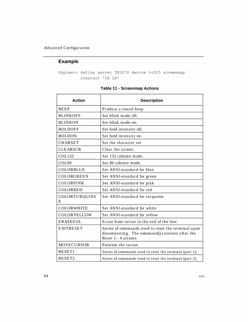
Advanced Configuration
94 0558
Example
Xyplex>> define server TN3270 device tv925 screenmap
clearscr “1B 2A”
Table 11 - Screenmap Actions
Action Description
BEEP Produce a sound beep.
BLINKOFF Set blink mode off.
BLINKON Set blink mode on.
BOLDOFF Set bold intensity off.
BOLDON Set bold intensity on.
CHARSET Set the character set.
CLEARSCR Clear the screen.
COL132 Set 132 column mode.
COL80 Set 80 column mode.
COLORBLUE Set ANSI-standard for blue
COLORGREEN Set ANSI-standard for green
COLORPINK Set ANSI-standard for pink
COLORRED Set ANSI-standard for red
COLORTURQUOISE
Set ANSI-standard for turquoise
COLORWHITE Set ANSI-standard for white
COLORYELLOW Set ANSI-standard for yellow
ERASEEOL Erase from cursor to the end of the line.
EXITRESET Series of commands used to reset the terminal upondisconnecting. The command(s) execute after theReset 1 - 4 actions.
MOVECURSOR Position the cursor.
RESET1 Series of commands used to reset the terminal (part 1).
RESET2 Series of commands used to reset the terminal (part 2).
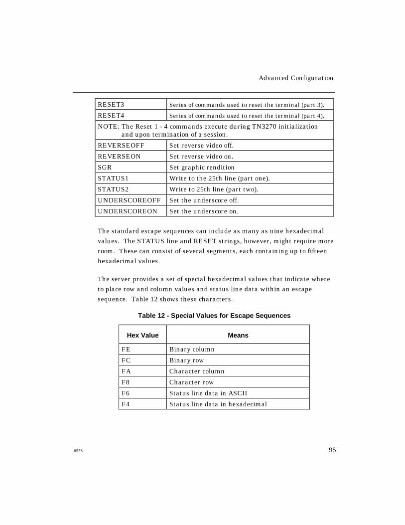
Advanced Configuration
0558 95
RESET3 Series of commands used to reset the terminal (part 3).
RESET4 Series of commands used to reset the terminal (part 4).
NOTE: The Reset 1 - 4 commands execute during TN3270 initializationand upon termination of a session.
REVERSEOFF Set reverse video off.
REVERSEON Set reverse video on.
SGR Set graphic rendition
STATUS1 Write to the 25th line (part one).
STATUS2 Write to 25th line (part two).
UNDERSCOREOFF Set the underscore off.
UNDERSCOREON Set the underscore on.
The standard escape sequences can include as many as nine hexadecimal
values. The STATUS line and RESET strings, however, might require more
room. These can consist of several segments, each containing up to fifteen
hexadecimal values.
The server provides a set of special hexadecimal values that indicate where
to place row and column values and status line data within an escape
sequence. Table 12 shows these characters.
Table 12 - Special Values for Escape Sequences
Hex Value Means
FE Binary column
FC Binary row
FA Character column
F8 Character row
F6 Status line data in ASCII
F4 Status line data in hexadecimal
Advanced Configuration
96 0558
For example, the escape sequence for the MOVECURSOR action on a
VT100 and its hexadecimal value including the FA character column
value is:
escape sequence: ESC [row;column H
hexadecimal value: 1B 5B F8 3B FA 4B
The STATUSLINE escape sequence for a CIT 224 and its hexadecimal
value, including the F4 status line value in hexadecimal, is:
escape sequence: esc P ); 1 N Q data esc \
hexadecimal value: 1B 50 30 3B 31 51 F4 1B 5C
Defining Screenmap Color
The Xyplex TN3270 protocol supports two color modes for IBM terminal
emulation: basic 4-color mode and extended 7-color mode. The basic 4-
color mode consists of green, red, blue, and white. The extended 7-color
mode includes the four basic colors and pink, yellow, and turquoise. The
mode you use depends on the colors that your users’ terminals support as
well as the colors that the IBM host application supports.
You define a screenmap escape sequence for each color that you plan to use.
You must also enable the TELNET TN3270 XTDATTRS setting at each port
where you plan to use the extended 7-color mode.
The following command defines color for the TN3270 screenmap. The
syntax descriptions show the ANSI-standard escape sequence for each color.
Refer to the terminal’s documentation if your users’ terminals support other
escape sequence types.
DEFINE SERVER TN3270 DEVICE device-name SCREENMAP
color-value "escape-sequence"
Advanced Configuration
0558 97
color-value Description
COLORRED "1B 5B 33 31 6D" ANSI-standard for red
COLORGREEN "1B 5B 33 32 6D" ANSI-standard for green
COLORBLUE "1B 5B 33 34 6D" ANSI-standard for blue
COLORYELLOW "1B 5B 33 33 6D" ANSI-standard for yellow
COLORWHITE "1B 5B 33 37 6D" ANSI-standard for white
COLORPINK "1B 5B 33 35 6D" ANSI-standard for pink
COLORTURQUOISE "1B 5B 33 36 6D" ANSI-standard for turquoise
Defining an Exit Reset String
The Exit Reset screenmap command sends a hexadecimal command string
of up to nine characters to the terminal when a TN3270 session terminates.
These characters are sent after any defined RESET strings have been
transmitted to the terminal. This feature is useful if you want to disable a
function such as Auto Scroll during a TN3270 session and then enable it
after the session ends. To do this, you disable the function (using the
appropriate command string) in one of the RESET screenmap commands,
and then enable it through the Exit Reset screenmap.
DEFINE SERVER TN3270 DEVICE device-name SCREENMAP EXITRESET
“hex-values”
Assigning a TN3270 Device to a Port
Use the following command to assign a TN3270 device to a port or group of
ports. You can assign a device that you have created, or one of the device
types that Xyplex supplies.
When you assign a device to a port, the server automatically assigns the
USENGLSH language translation table to that port. If you want to assign a
different translation table to the port, refer to the section “Assigning a
Translation Table to a Port”.
Advanced Configuration
98 0558
DEFINE/SET PORT port-list TELNET TN3270 DEVICE [device-name]
[NONE]
The value NONE disables the terminal emulation feature at the
specified port(s).
Example
Xyplex>> define port 4-16 telnet 3270 device tv925
Assigning a Default Port Number for TN3270 Sessions
This feature lets you assign a default port number for the access server to
use when forming a TN3270 session. If you do not specify a default, the
access server uses the default port for a Telnet session, which is 23.
DEFINE/SET PORT [port-list] TELNET TN3270 DEFAULT PORT
[port-number]
Assigning Userdata Strings for Telnet Dedicated Services
Userdata string functions provide you with a way to add a userdata
string to a Telnet dedicated service. The userdata string is passed to
the network partner upon connection.
Adding A Userdata String
Enter the following to define a userdata string for a dedicated port:
define port port-number telnet dedicated [service] [ip-address/domain name] userdata "userdata_string"
The keyword "telnet" is required. If it is omitted, the user will be unable to
enter the "userdata" string.

Advanced Configuration
0558 99
Deleting a Userdata String
You can keep the service and delete the userdata string, or you can delete
both the service and the string:
To keep the service and delete the userdata string:
define port port-number telnet dedicated [service] [ip-address/domain name] userdata ""
To delete the service and the userdata string:
define port port-number dedicated none
Modifying a Userdata String
To modify a userdata string, you must redefine the service as well.
Using Userdata Strings Characters
The following guidelines apply to the characters within a userdata
character string.
1. The string, when computed can store up to 16 characters.
2. The range is as follows:
- All printable ascii characters.
- Special escaped ascii characters, including:
\b - backspace
\t - tab
\n - linefeed
\f - form feed
\v - vertical tab
Advanced Configuration
100 0558
\r - carriage return
\\ - backslash
3. All non-printable ascii characters in the form of \000 -\377 octal(hex
00 - FF).
4. The leading backslash (\) is required for the special escaped and octal
characters to be interpreted correctly. In fact, if entering an octal, you
will receive an error message if you do not use a value in the range of\000 - \377.
The above covers the entire ascii chart from 0-255.
Displaying the Userdata String
The userdata string displays underneath the Dedicated Service display
on the Show Port screen. The screen displays characters just as you
entered them, with the following minor exceptions:
• If an octal equivalent of a printable character or a special escape
character is entered, then that printable or special escape character will
be displayed.
• If an octal \377(hex FF) is entered, then it will be doubled. (Telnet
interprets the FF has an IAC.)
• If spaces (spacebar) are imbedded in the string, they will be
interpreted as a hex 20 and sent up to the connection partner. Do not
enter spaces within the string unless you want to pass them to the
connection partner.
Sample Userdata Strings
The following examples show how userdata stings convert and display.

Advanced Configuration
0558 101
Example 1
The user enters xyplex\r\n, as the userdata string. The string is
displayed as is, and computes down to a total of 8 characters. The \r is a
carriage return(hex 0D)and the \n, a linefeed(hex 0A).
The hex equivalent of the above string 78 79 70 6c 65 78 0d 0a is sent
to the connection partner.
NOTE: Keep in mind that all the rules regarding telnet newline still
apply. If a \r (carriage return) is part of the entered string, either a
null, linefeed, or nothing will be appended to it, depending on thesetting of the telnet newline characteristic.
Example 2
A user enters the string \141\142\143\015\012\000. The string is
displayed as abc\r\n\000. The string is sent with Telnet as hex 61 62 63
0d 0a 00.
Note that, although 4 keystrokes were entered for \141, only one character
, a, was stored and sent.
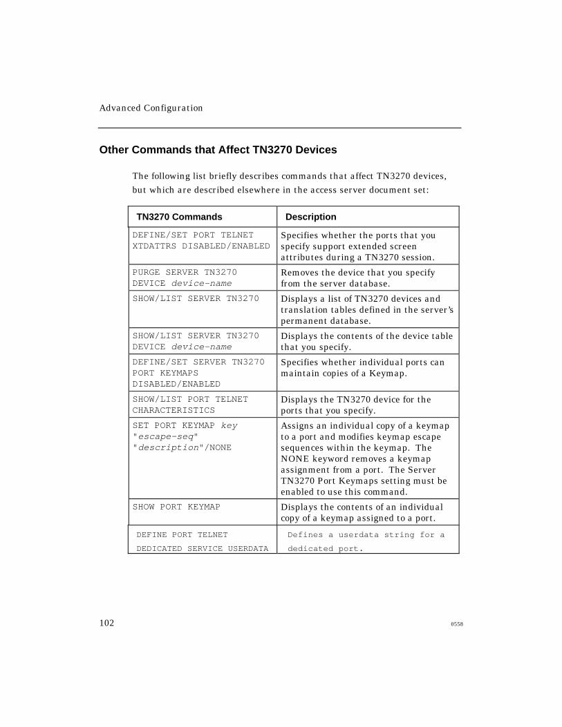
Advanced Configuration
102 0558
Other Commands that Affect TN3270 Devices
The following list briefly describes commands that affect TN3270 devices,
but which are described elsewhere in the access server document set:
TN3270 Commands Description
DEFINE/SET PORT TELNETXTDATTRS DISABLED/ENABLED
Specifies whether the ports that youspecify support extended screenattributes during a TN3270 session.
PURGE SERVER TN3270DEVICE device-name
Removes the device that you specifyfrom the server database.
SHOW/LIST SERVER TN3270 Displays a list of TN3270 devices andtranslation tables defined in the server’spermanent database.
SHOW/LIST SERVER TN3270DEVICE device-name
Displays the contents of the device tablethat you specify.
DEFINE/SET SERVER TN3270PORT KEYMAPSDISABLED/ENABLED
Specifies whether individual ports canmaintain copies of a Keymap.
SHOW/LIST PORT TELNETCHARACTERISTICS
Displays the TN3270 device for theports that you specify.
SET PORT KEYMAP key"escape-seq""description"/NONE
Assigns an individual copy of a keymapto a port and modifies keymap escapesequences within the keymap. TheNONE keyword removes a keymapassignment from a port. The ServerTN3270 Port Keymaps setting must beenabled to use this command.
SHOW PORT KEYMAP Displays the contents of an individualcopy of a keymap assigned to a port.
DEFINE PORT TELNET
DEDICATED SERVICE USERDATA
Defines a userdata string for a
dedicated port.
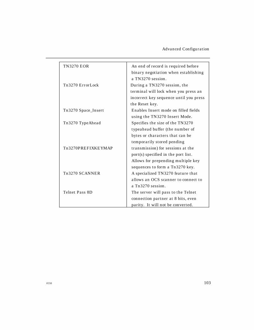
Advanced Configuration
0558 103
TN3270 EOR
Tn3270 ErrorLock
Tn3270 Space_Insert
Tn3270 TypeAhead
Tn3270PREFIXKEYMAP
Tn3270 SCANNER
Telnet Pass 8D
An end of record is required before
binary negotiation when establishing
a TN3270 session.
During a TN3270 session, the
terminal will lock when you press an
incorrect key sequence until you press
the Reset key.
Enables Insert mode on filled fields
using the TN3270 Insert Mode.
Specifies the size of the TN3270
typeahead buffer (the number of
bytes or characters that can be
temporarily stored pending
transmission) for sessions at the
port(s) specified in the port list.
Allows for prepending multiple key
sequences to form a Tn3270 key.
A specialized TN3270 feature that
allows an OCS scanner to connect to
a Tn3270 session.
The server will pass to the Telnet
connection partner at 8 bits, even
parity. It will not be converted.
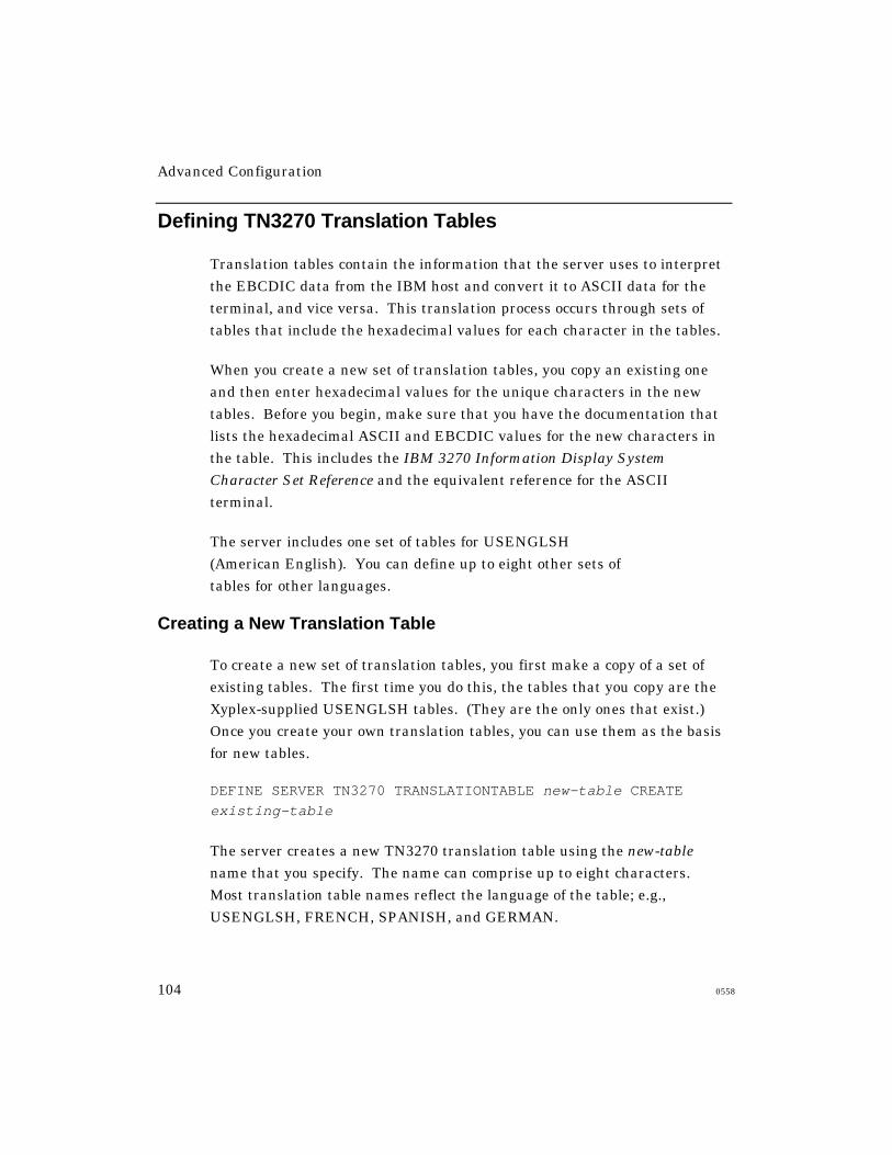
Advanced Configuration
104 0558
Defining TN3270 Translation Tables
Translation tables contain the information that the server uses to interpret
the EBCDIC data from the IBM host and convert it to ASCII data for the
terminal, and vice versa. This translation process occurs through sets of
tables that include the hexadecimal values for each character in the tables.
When you create a new set of translation tables, you copy an existing one
and then enter hexadecimal values for the unique characters in the new
tables. Before you begin, make sure that you have the documentation that
lists the hexadecimal ASCII and EBCDIC values for the new characters in
the table. This includes the IBM 3270 Information Display System
Character Set Reference and the equivalent reference for the ASCII
terminal.
The server includes one set of tables for USENGLSH
(American English). You can define up to eight other sets of
tables for other languages.
Creating a New Translation Table
To create a new set of translation tables, you first make a copy of a set of
existing tables. The first time you do this, the tables that you copy are the
Xyplex-supplied USENGLSH tables. (They are the only ones that exist.)
Once you create your own translation tables, you can use them as the basis
for new tables.
DEFINE SERVER TN3270 TRANSLATIONTABLE new-table CREATE
existing-table
The server creates a new TN3270 translation table using the new-table
name that you specify. The name can comprise up to eight characters.
Most translation table names reflect the language of the table; e.g.,
USENGLSH, FRENCH, SPANISH, and GERMAN.
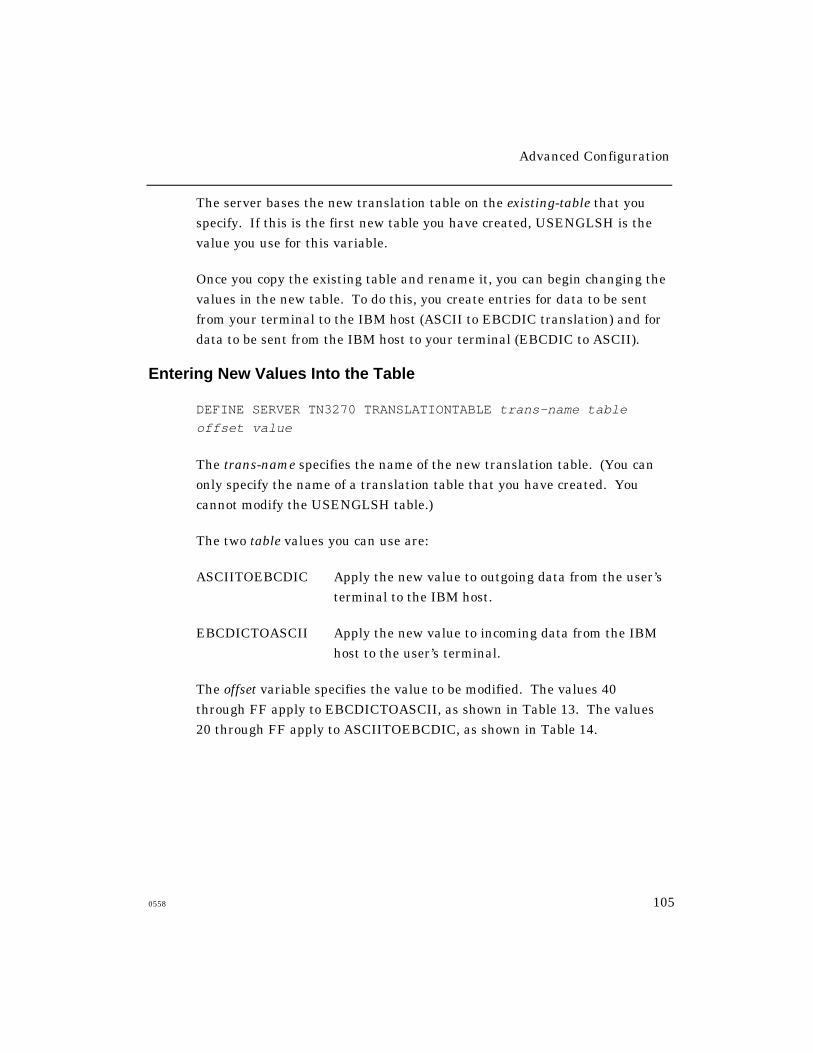
Advanced Configuration
0558 105
The server bases the new translation table on the existing-table that you
specify. If this is the first new table you have created, USENGLSH is the
value you use for this variable.
Once you copy the existing table and rename it, you can begin changing the
values in the new table. To do this, you create entries for data to be sent
from your terminal to the IBM host (ASCII to EBCDIC translation) and for
data to be sent from the IBM host to your terminal (EBCDIC to ASCII).
Entering New Values Into the Table
DEFINE SERVER TN3270 TRANSLATIONTABLE trans-name table
offset value
The trans-name specifies the name of the new translation table. (You can
only specify the name of a translation table that you have created. You
cannot modify the USENGLSH table.)
The two table values you can use are:
ASCIITOEBCDIC Apply the new value to outgoing data from the user’s
terminal to the IBM host.
EBCDICTOASCII Apply the new value to incoming data from the IBM
host to the user’s terminal.
The offset variable specifies the value to be modified. The values 40
through FF apply to EBCDICTOASCII, as shown in Table 13. The values
20 through FF apply to ASCIITOEBCDIC, as shown in Table 14.

Advanced Configuration
106 0558
The value variable specifies the new hexadecimal translation table entry.
The values 20 through FF apply to EBCDICTOASCII and the values 40
through FF apply to ASCIITOEBCDIC. (This is the reverse of the offset
values.)
Table 13 - EBCDICTOASCII, USENGLSH Translation Table
0 1 2 3 4 5 6 7 8 9 a b c d e f
0 20 20 20 20 20 26 2d 20 20 20 20 20 7b 7d 5c 30
1 20 20 20 20 20 20 2f 20 61 6a 7e 20 41 4a 20 31
2 20 20 20 20 20 20 20 20 62 6b 73 20 42 4b 53 32
3 20 20 20 20 20 20 20 20 63 6c 74 20 43 4c 54 33
4 20 20 20 20 20 20 20 20 64 6d 75 20 44 4d 55 34
5 20 20 20 20 20 20 20 20 65 6e 76 20 45 4e 56 35
6 20 20 20 20 20 20 20 20 66 6f 77 20 46 4f 57 36
7 20 20 20 20 20 20 20 20 67 70 78 20 47 50 58 37
8 20 20 20 20 20 20 20 20 68 71 79 20 48 51 59 38
9 20 20 20 20 20 20 20 60 69 72 7a 20 49 52 5a 39
a 20 20 20 20 5b 21 7c 3a 20 20 20 20 20 20 20 20
b 20 20 20 20 2e 24 2c 23 20 20 20 20 20 20 20 20
c 20 20 20 20 3c 2a 25 40 20 20 20 20 20 20 20 20
d 20 20 20 20 28 29 5f 27 20 20 20 20 20 20 20 20
e 20 20 20 3b 2b 3b 3e 3d 20 20 20 20 20 20 20 20
f 20 20 20 2a 7c 5e 3f 22 20 20 20 20 20 20 20 20

Advanced Configuration
0558 107
Table 14 - ASCIITOEBCDIC, USENGLSH Translation Table
0 1 2 3 4 5 6 7 8 9 a b c d e f
0 00 00 40 f0 7c d7 79 97 00 00 00 00 00 00 00 00
1 00 00 5a f1 c1 d8 81 98 00 00 00 00 00 00 00 00
2 00 00 7f f2 c2 d9 82 99 00 00 00 00 00 00 00 00
3 00 00 7b f3 c3 e2 83 a2 00 00 00 00 00 00 00 00
4 00 00 5b f4 c4 e3 84 a3 00 00 00 00 00 00 00 00
5 00 00 6c f5 c5 e4 85 a4 00 00 00 00 00 00 00 00
6 00 00 50 f6 c6 e5 86 a5 00 00 00 00 00 00 00 00
7 00 00 7d f7 c7 e6 87 a6 00 00 00 00 00 00 00 00
8 00 00 4d f8 c8 e7 88 a7 00 00 00 00 00 00 00 00
9 00 00 5d f9 c9 e8 89 a8 00 00 00 00 00 00 00 00
a 00 00 5c 7a d1 e9 91 a9 00 00 00 00 00 00 00 00
b 00 00 4e 5e d2 4a 92 c0 00 00 00 00 00 00 00 00
c 00 00 6b 4c d3 e0 93 6a 00 00 00 00 00 00 00 00
d 00 00 60 7e d4 5a 94 d0 00 00 00 00 00 00 00 00
e 00 00 4b 6e d5 5f 95 a1 00 00 00 00 00 00 00 00
f 00 00 61 6f d6 6d 96 00 00 00 00 00 00 00 00 00
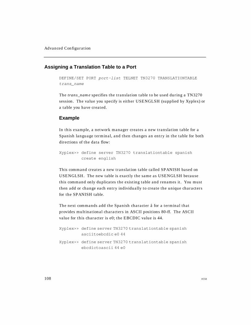
Advanced Configuration
108 0558
Assigning a Translation Table to a Port
DEFINE/SET PORT port-list TELNET TN3270 TRANSLATIONTABLE
trans_name
The trans_name specifies the translation table to be used during a TN3270
session. The value you specify is either USENGLSH (supplied by Xyplex) or
a table you have created.
Example
In this example, a network manager creates a new translation table for a
Spanish language terminal, and then changes an entry in the table for both
directions of the data flow:
Xyplex>> define server TN3270 translationtable spanish
create english
This command creates a new translation table called SPANISH based on
USENGLSH. The new table is exactly the same as USENGLSH because
this command only duplicates the existing table and renames it. You must
then add or change each entry individually to create the unique characters
for the SPANISH table.
The next commands add the Spanish character å for a terminal that
provides multinational characters in ASCII positions 80-ff. The ASCII
value for this character is e0; the EBCDIC value is 44.
Xyplex>> define server TN3270 translationtable spanishasciitoebcdic e0 44
Xyplex>> define server TN3270 translationtable spanishebcdictoascii 44 e0
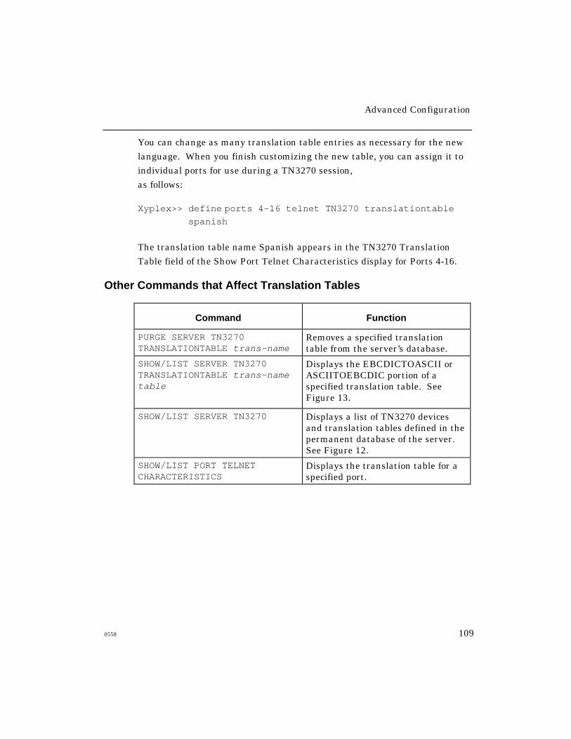
Advanced Configuration
0558 109
You can change as many translation table entries as necessary for the new
language. When you finish customizing the new table, you can assign it to
individual ports for use during a TN3270 session,
as follows:
Xyplex>> define ports 4-16 telnet TN3270 translationtablespanish
The translation table name Spanish appears in the TN3270 Translation
Table field of the Show Port Telnet Characteristics display for Ports 4-16.
Other Commands that Affect Translation Tables
Command Function
PURGE SERVER TN3270TRANSLATIONTABLE trans-name
Removes a specified translationtable from the server’s database.
SHOW/LIST SERVER TN3270TRANSLATIONTABLE trans-nametable
Displays the EBCDICTOASCII orASCIITOEBCDIC portion of aspecified translation table. SeeFigure 13.
SHOW/LIST SERVER TN3270 Displays a list of TN3270 devicesand translation tables defined in thepermanent database of the server.See Figure 12.
SHOW/LIST PORT TELNETCHARACTERISTICS
Displays the translation table for aspecified port.
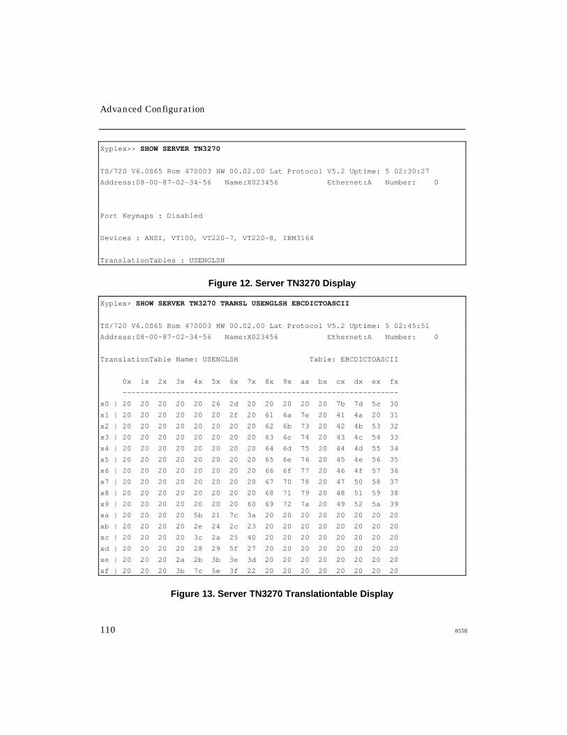
Advanced Configuration
110 0558
Xyplex>> SHOW SERVER TN3270
TS/720 V6.0S65 Rom 470003 HW 00.02.00 Lat Protocol V5.2 Uptime: 5 02:30:27
Address:08-00-87-02-34-56 Name:X023456 Ethernet:A Number: 0
Port Keymaps : Disabled
Devices : ANSI, VT100, VT220-7, VT220-8, IBM3164
TranslationTables : USENGLSH
Figure 12. Server TN3270 Display
Xyplex> SHOW SERVER TN3270 TRANSL USENGLSH EBCDICTOASCII
TS/720 V6.0S65 Rom 470003 HW 00.02.00 Lat Protocol V5.2 Uptime: 5 02:45:51
Address:08-00-87-02-34-56 Name:X023456 Ethernet:A Number: 0
TranslationTable Name: USENGLSH Table: EBCDICTOASCII
0x 1x 2x 3x 4x 5x 6x 7x 8x 9x ax bx cx dx ex fx
--------------------------------------------------------------
x0 | 20 20 20 20 20 26 2d 20 20 20 20 20 7b 7d 5c 30
x1 | 20 20 20 20 20 20 2f 20 61 6a 7e 20 41 4a 20 31
x2 | 20 20 20 20 20 20 20 20 62 6b 73 20 42 4b 53 32
x3 | 20 20 20 20 20 20 20 20 63 6c 74 20 43 4c 54 33
x4 | 20 20 20 20 20 20 20 20 64 6d 75 20 44 4d 55 34
x5 | 20 20 20 20 20 20 20 20 65 6e 76 20 45 4e 56 35
x6 | 20 20 20 20 20 20 20 20 66 6f 77 20 46 4f 57 36
x7 | 20 20 20 20 20 20 20 20 67 70 78 20 47 50 58 37
x8 | 20 20 20 20 20 20 20 20 68 71 79 20 48 51 59 38
x9 | 20 20 20 20 20 20 20 60 69 72 7a 20 49 52 5a 39
xa | 20 20 20 20 5b 21 7c 3a 20 20 20 20 20 20 20 20
xb | 20 20 20 20 2e 24 2c 23 20 20 20 20 20 20 20 20
xc | 20 20 20 20 3c 2a 25 40 20 20 20 20 20 20 20 20
xd | 20 20 20 20 28 29 5f 27 20 20 20 20 20 20 20 20
xe | 20 20 20 2a 2b 3b 3e 3d 20 20 20 20 20 20 20 20
xf | 20 20 20 3b 7c 5e 3f 22 20 20 20 20 20 20 20 20
Figure 13. Server TN3270 Translationtable Display
Advanced Configuration
0558 111
Using Alternate Keymaps
Alternate keymaps enable you to define multiple sets of input sequences for
users’ terminal keyboards all mapping to the same function. For
example, a user can invoke the TN3270 PF1 function through any of these
methods:
• The numeric keypad 1, or
• ESC followed by the digit 1, or
• <CTRL> <A>.
You can define up to three alternate keymaps, giving a total of four unique
keyboard sequences that can be mapped to a single TN3270 function (the
original sequence plus three alternates).
NOTE: The server does not check for errors when you map alternate
keymaps to a device. It does so when the user attempts to establish
a TN3270 session with the host.
The first two alternate sequences are displayed on the TN3270 Showkeys
display, in addition to the regular primary keymap.
Defining the Alternate Keymaps
Alternate keymaps are stored as TN3270 device table entries (as are normal
keymaps). The maximum number of TN3270 device table entries is 20. Use
this command to create an entry to hold the alternate keymap:
DEFINE SERVER TN3270 DEVICE device-name CREATE EMPTY
When you use this command, the Show Server TN3270 Device Name
command does not display nonessential information.
Advanced Configuration
112 0558
IMPORTANT
Only use the Create Empty option for alternate keymaps. A device table
entry that you specify as a port’s Telnet TN3270 device name must not be
created EMPTY.
Use this command to map an alternate keymap to a TN3270 device
table entry:
DEFINE SERVER TN3270 DEVICE device-name KEYMAP ALTMAP name
The device-name specifies the name of the TN3270 device table entry to
which the alternate keymap is being assigned. The name identifies the
TN3270 device table entry that contains the alternate keymap. Specifying
NONE as the name disables any alternate keymap for the TN3270 device.
Example
The following commands modify the distributed VT100 device and add two
alternate keymaps. As a result, the TN3270 function keys PA1-PA3 can
also be invoked by the sequences ESC-1 through ESC-3, and Control/A-1
through Control/A-3.
DEFINE SERVER TN3270 DEV VT100 KEYMAP ALTMAP TV925
DEFINE SERVER TN3270 DEV TV925 CREATE EMPTY
DEFINE SERVER TN3270 DEV TV925 KEYMAP PA1 "1B 31" "ESC-1"
DEFINE SERVER TN3270 DEV TV925 KEYMAP PA2 "1B 32" "ESC-2"
DEFINE SERVER TN3270 DEV TV925 KEYMAP PA3 "1B 33" "ESC-3"
DEFINE SERVER TN3270 DEV TV925 KEYMAP ALTMAP PT250
DEFINE SERVER TN3270 DEV PT250 CREATE EMPTY
DEFINE SERVER TN3270 DEV PT250 KEYMAP PA1 "01 31" "CTRA1"
DEFINE SERVER TN3270 DEV PT250 KEYMAP PA2 "01 32" "CTRA2"
DEFINE SERVER TN3270 DEV PT250 KEYMAP PA3 "O1 33" "CTRA3"
Advanced Configuration
0558 113
Associated Displays
The Show Server TN3270 Device command displays the names of alternate
keymap devices. The SHOWKEYS display for a TN3270 session displays
the descriptions for up to three keymaps; the primary keymap plus two
alternate keymaps. Each description is separated by a comma.
Error Codes
The creation of an operational keymap occurs during the opening of a
TN3270 session. A list of possible errors follows:
-1000- Cannot use reserved TN3270 device name
Explanation: The names EMPTY and NONE are reserved names and
cannot be used as device names. This error is displayed
during command processing, when you define the device name
with a reserved name.
Action: Define a device name other than EMPTY or NONE.
-1001- TN3270 alternate keymap 'name' does not exist
Explanation: You have attempted to establish a TN3270 session in which
the alternate keymap name does not exist in the list of
devices.
Action: Check the List/Show Server TN3270 display for devicesthat have been created. Use the command DEFINE SERVER
TN3270 DEVICE name CREATE EMPTY.

Advanced Configuration
114 0558
-1002- TN3270 maximum number of alternate keymaps exceeded
Explanation: You have defined more than three alternate keymaps or you
have defined an alternate keymap that points back to itself (as
shown in the following example).
define server TN3270 dev vt100 keymap altmap
vt100c
define server TN3270 dev vt100c keymap altmap
vt100
Action: View the LIST/SHOW SERVER TN3270 DEVICE name display
and check the alternate device name. Then enter the
command again using the alternate name for the name and
check its alternate device name.
If they are the same, the alternate keymaps are pointing back
to each other. If they are not the same, continue using this
command until you reach the fourth alternate keymap name.
Correct the problem by defining the third alternate keymap as
having no alternate map.
Example: Keymap A points to altmap B /* ok */
Keymap B points to altmap C /* ok */
Keymap C points to altmap D /* ok */
Keymap D points to altmap E /* NOT ok */
To correct: DEFINE SERVER TN3270 DEVICE D KEYMAP ALTMAP none

Advanced Configuration
0558 115
-1003- TN3270 maximum keymap size exceeded
Explanation: More than 500 keys have been mapped into the device’s token
table. Given the default of 59 tokens plus three alternate
maps with 59 keymaps defined, this is an unlikely error.
Action: Limit the amount of tokens to less than 500.
-1004- TN3270 could not allocate memory to start session
Explanation: TN3270_INIT failed allocating (reserving portions of) memory
for building a keymap.
Action: A corrupted keymap might exist or there might be a shortage
of memory. Contact Xyplex Customer Support.
-1005- TN3270 error building key mappings
Explanation: This error is displayed in conjunction with one of the above
errors and indicates that TN3270 has failed to build a keymap
for the device, and that the TN3270 session has terminated.
Action: Refer to the actions for errors 1001-1004.
Advanced Configuration
116 0558
Using Line 25 as a Status Line
To configure the access server to support the use of the 25th line of a VT330
or VT420 terminal as a status line, follow these steps:
1. Change the terminal display.
2. Select the 25th line.
3. Activate the 25th line.
Change the Terminal Display
Using the terminal’s Display Setup menu, enable the “Host
Writable Status Display” setting. The terminal’s default setting is
“No Status Display.”
Select the 25th Line
For the TN3270 session to write to the 25th line, you must define
hexadecimal values that “select” the 25th line using any of the four
RESET screenmap commands. An example follows:
Xyplex>> define server TN3270 device vt330 screenmap reset3
“1B 5B 32 24 2D”
This command defines the control function that enables the host to select
the type of status line to be displayed on line 25. The hex value 32 used in
the preceding example denotes “Host Writable Status Line.”

Advanced Configuration
0558 117
Activate the 25th Line
To activate the 25th line, use the STATUS1 screenmap command. An
example follows:
Xyplex>> define server TN3270 device vt330 screenmap status1
“1b 5b 31 24 7d 1b 5b 3b 48 f6 1b 5b 30 24 7d”
The 15 hexadecimal values in the STATUS1 screenmap denote
the following:
• The first five hex values select the active status display as the
status line and specify that the terminal sends data to the status
line only.
• The next four values position the cursor at the beginning of the
status line.
• The F6 is a special value that instructs TN3270 to write the status
line data in ASCII. Changing the value to F4 would instruct
TN3270 to display the status line in hexadecimal.
• The last five hex values select the active status display as the main
display, instructing the terminal to send data to the main (1 - 24)
lines only. (This is basically a reset. If the last five values were not
entered, all TN3270 data including the status line would be
displayed on the 25th line.)

Advanced Configuration
118 0558
Status Line Information
Status Column Meaning (Action)
S 1 Subsystem-ready
A 2 MyJob value indicating connection to the hostapplication
X ( ) 8 Terminal wait. (Wait for the condition to clear.)
X <*> 8 WrongPlace The entry you attempted is invalid forthat position on the screen; for example, entering datainto a protected field. (Press the RESET key; move thecursor to the correct position.)
X *NUM 8 Numeric-only field. You tried to enter a lowercasealphabet character into a numeric field. (Press theRESET key and correct the data in the field.)
X *> 8 You tried to enter too much data into a field on thescreen. (Press the RESET key and enter the correctamount of data.)
X ? + 8 Input not accepted/understood. (Press the RESET key;check the screen, and try to enter the data again.)
X -S 8 Invalid key combination; key is not mapped to akeymap. (Press the RESET key to continue.)
^ 8 Insert status.
XPrinting
8 Printing in progress.
XPrtBusy
8 Printer is busy.
XNoPrinter
8 Printer is not attached. (Press RESET to continue.)

Advanced Configuration
0558 119
Local Printer Support
You can assign two or more local printers for TN3270 screen printing. To
enable support for screen printing, you assign the ACCESS PRT3270
characteristic to one or more ports. The TN3270 printer ports must have
valid device names.
To assign a port to a specific printer or to any available printer, use
this command:
DEFINE/SET PORT port-list TELNET TN3270 PRINTERPORT [port-numb]
[ANY]
The port-list specifies one or more server ports to assign to a printer port
for local TN3270 screen printing.
The ANY keyword specifies that the server may use any available port with
Access PRT3270 enabled to print the screen.
A port-number can be any valid port number with ACCESS PRT3270
enabled and a valid TN3270 device name.
The Show/List/Monitor Ports Telnet Characteristics display includes the
TN3270 printer port assignment, or ANY if you have not specified a port.
The following commands set up normal 80-column print screen handling on
a server port:
DEFINE PORT port-list ACCESS PRT3270
DEFINE PORT port-list TELNET TN3270 DEVICE VT100
DEFINE PORT port-list AUTOBAUD DISABLED
DEFINE PORT port-list SPEED baud-rate
DEFINE PORT port-list PARITY parity
DEFINE PORT port-list CHARACTER SIZE character-size
LOGOUT PORT port-list
Advanced Configuration
120 0558
Setting Up Daemons
Daemons are system processes that run in background mode at hosts, or
at network devices such as access servers. Daemons are often used in
UNIX environments and TCP/IP networks to exchange information about
network activity, or to manage resources such as printers.
Access servers support these environments by supporting a number of
standard daemons. Some benefits of this support include:
• Improving the UNIX “look and feel” of the server, making it easier
for UNIX users to use the server.
• Enabling the server to take advantage of information that is
typically available in a TCP/IP network, and to make this
information available for host users, too.
This section describes how to set up the following daemons at the
access server:
• fingerd Provides a method for exchanging information among
hosts about users who are logged on to a server, using the Finger
User Information Protocol (RFC 1288).
• routed Provides a method for exchanging routing information
among gateways or hosts, using the Routing Information Protocol
(RFC 1058).
• rwhod Provides a method for collecting information about domain
names on the network by listening to “rwho” messages and adding
currently unknown domain names to the domain name table.
Advanced Configuration
0558 121
The server supports additional daemons, which are described in other
documents. These include:
• lpd Provides a method for exchanging print jobs between hosts and
managing jobs that are in a print queue, using the protocol defined by
RFC 1179. Setup and configuration of this daemon is described in the
guide Configuring Printer Serving Features.
• syslogd Provides a central facility for logging messages about server
events. These messages can be logged at the server and/or in a file at a
UNIX host.
Xyplex also supplies a host-based daemon, csportd, that you use to
manage resources at server ports. This daemon provides a general-
purpose tool for making connections to a port and “piping” data to or
from that port. Setup and configuration of this daemon is described in
Printers section of this guide.
Enabling Daemons
Use these commands to enable daemons:
Xyplex>> define server daemon fingerd enabled
Xyplex>> define server daemon routed enabled
Xyplex>> define server daemon rwhod enabled
In place of the DEFINE SERVER DAEMON ROUTED ENABLED command, you
can use:
Xyplex>> define server rip state enabled
Xyplex>> define rip state enabled
The server responds with a message similar to:
-705- Change leaves approximately nnnnn bytes free.
Advanced Configuration
122 0558
NOTE: “Setting Up the Access Server” discusses the amount of memory
used by the daemons.
Reboot the server after issuing the command for the change to
take effect.
Using the Finger Daemon (fingerd)
The finger daemon (fingerd) provides a method for exchanging information
between hosts about users who are logged on to a server, using the Finger
User Information Protocol (RFC 1288). The daemon responds to requests
made at a host for information about a user.
Once the daemon is enabled, no other user activity is required. The daemon
simply makes information about ports and users available when a user at a
host makes a finger request.
Typically, hosts allow you to specify either a domain name or an IP address
when making finger requests. Some implementations support options such
as “verbose.” Refer to your host’s finger daemon documentation for
information about these options.
Some implementations also allow a finger request to be forwarded through a
host or server to another host or server. The Xyplex finger implementation
does not forward these requests.
Xyplex servers always respond with one of two display types: a
standard display and a verbose format display. This is an example of
the standard display:
% finger @172.19.197.98
[172.19.197.98]
User Name Port Idle Login Port Name Status
Charlie 8 00:01:10 12-Jul 11:27 PORT_8 Wait Input

Advanced Configuration
0558 123
This is an example of the verbose display:
xap> finger -l [email protected]
[172.19.197.98]
Port 8:: Charlie Login: 12-Jul 1993 11:27 Status: Connected
+Session 1:: UNIXHOST
Session 2:: VMSHOST
The following table describes each field in the finger displays:
Field Description
Username A user-supplied name; the name given to the port throughthe Port Username setting; or “(Remote)” for ports with aremote (host-initiated) connection.
Port The access server port number.
Idle The amount of time that the port has been idle.
Login The time when the port was logged in.
Port Name The name of the port. The default name is PORT_n, wheren is the physical port number. You can assign a differentname through the Define/Set Port Name command.
Session The name of the host or server destination of any sessionsrunning at the port. A plus sign (+) indicates that thesession is currently active. If a remote connection has beenformed with the port, the service is displayed as “RemoteConnect.”
Status The current status of the port, which can be:
Autobaud Being “autobauded” (selecting a portspeed).
Available The port’s Access setting is Remote orDynamic, and the port is not busy.
Check Modem Verifying that modem signals are beingproperly asserted.
Check Connect Determining the status (accepted orrejected) of a pending connection.
Connected Currently connected to a LAT service orTelnet destination.

Advanced Configuration
124 0558
Connect Wait Waiting to retry a connection attempt(used when Port Autoconnect isEnabled).
Connecting Currently attempting to connect to aLAT service or Telnet destination.
Dialback Wait Waiting for the remote modem toanswer a dial-back call.
Disconnected A session was disconnected (forexample, because it was inactive for toolong).
Disconnecting A session is disconnecting from a LATservice or Telnet destination.
Executing Cmd Executing a command from the localcommand mode.
Finding Script Searching for a script file via TFTP readrequests.
First DialbackLogin
Making a first attempt to locate a dial-back script.
Idle Currently not in use.
Loading Script The port has located a script file and isreceiving the file from the script server.
Local Mode Logged on to the server; currently inlocal command mode.
Locked Disabled through the Lock command.
Login Waiting for the user to enter a login orKerberos password.
Login Wait Disabled (for 60 seconds) because anincorrect password has been entered, orbecause a dial-back attempt failed.
Logout Logged out.
Password Waiting for the password required by apassword-protected LAT service.
PPP Used for the Point-to-Point Protocol..
Reset Reverting to stored configuration.
Advanced Configuration
0558 125
Retry Connect Trying to connect to a service that waspreviously unavailable (used when PortAutoconnect is Enabled).
Running Script Executing the commands in a script file.
Second DialbackLogin
Making a second attempt to locate adial-back script (the port searches thedirectory path “above” the path specifiedfor this script server).
Slip Used for Serial Link Internet Protocol.
Suspended The user has entered the local-switchcharacter; the session is beingsuspended.
Test Wait Executing a Test Service command.
Test Out Outputting the results of a Test Servicecommand.
Wait Input The port is at the local prompt (waitingfor the user to enter a command).
Wait Logout Waiting for modem control signals to bedeasserted.
Wait Output Completing display output beforelogging out.
Wait Queue A connection request from this port is ina queue.
Wait Session The session is being disconnected.
Using the Route Daemon (routed)
This daemon provides a method for exchanging routing information among
gateways or hosts, using the Routing Information Protocol (RIP), as defined
by RFC 1058. The access server uses RIP to learn about IP routes from
hosts or gateways.
The server listens for routing messages and updates its routing tables, but
does not transmit any routing information to the default primary or
secondary gateways or hosts (The server is a “silent” or “passive” router.)
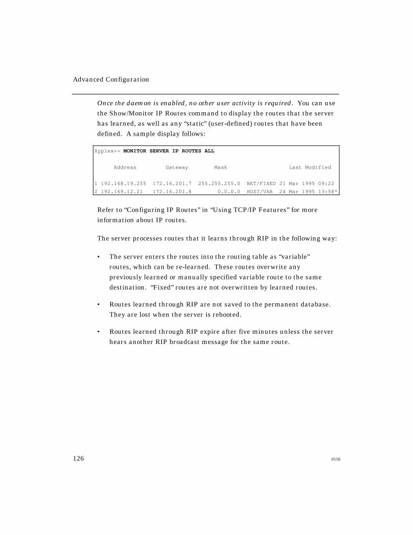
Advanced Configuration
126 0558
Once the daemon is enabled, no other user activity is required. You can use
the Show/Monitor IP Routes command to display the routes that the server
has learned, as well as any “static” (user-defined) routes that have been
defined. A sample display follows:
Xyplex>> MONITOR SERVER IP ROUTES ALL
Address Gateway Mask Last Modified
1 192.168.19.255 172.16.201.7 255.255.255.0 NET/FIXED 21 Mar 1995 09:22
2 192.169.12.21 172.16.201.8 0.0.0.0 HOST/VAR 24 Mar 1995 13:58*
Refer to “Configuring IP Routes” in “Using TCP/IP Features” for more
information about IP routes.
The server processes routes that it learns through RIP in the following way:
• The server enters the routes into the routing table as “variable”
routes, which can be re-learned. These routes overwrite any
previously learned or manually specified variable route to the same
destination. “Fixed” routes are not overwritten by learned routes.
• Routes learned through RIP are not saved to the permanent database.
They are lost when the server is rebooted.
• Routes learned through RIP expire after five minutes unless the server
hears another RIP broadcast message for the same route.

Advanced Configuration
0558 127
Using the rwho Daemon (rwhod)
This daemon provides a method for collecting information about domain
names on the network by listening to “rwho” messages and adding currently
unknown domain names to the domain name table.
Once the daemon is enabled, no other user activity is required. You can use
the Show/List/Monitor Domain command to display the domain names that
the server has learned, or any manually defined domain names. A sample
display follows:
Xyplex> show domain
Internet Domain 19 Jan 1989 08:23:58
Entry Address TTL Source Name
1 192.168.119.100 100 Pri UNIXHOST.COM
2 192.168.119.200 24 Sec FINANCESUN.COM
3 192.168.119.240 Loc NET5000.COM
4 192.168.119.242 Loc MAX1600.COM
5 192.168.119.216 1438 Who ENGHOST.COM
When the rwhod daemon is enabled, any domain names that have been
learned through rwho messages are indicated as having “Who” as the
source in the Show/Monitor Domain display. Refer to
Using the Server as a Domain Name Server in “Using TCP/IP Features”
for more information about IP routes.
When the server receives an rwho message, if the domain name already
exists in the domain name table and its source is either the primary
or secondary name server the entry is overwritten with “Who” as the
source and a time-to-live of 1440. If the domain name exists in the
table, and its source is “local,” the entry is not overwritten.
Advanced Configuration
128 0558
Using Nested Menus
This section explains how to use the Nested Menu feature. It covers the
following topics:
• About the Nested Menu Feature
• Setting Up the Script Servers
• Creating the Nested Menu File
• Configuring the Access Server to Support Nested Menus
• Sample Nested Menu Files
You can enable or require nested menus at specific ports, or through a
user’s login script. “Using Scripts” explains how to create login scripts.
Note that you cannot enable both the Nested Menu feature and the Menu
feature on the same port.
Memory Requirements
The access server must have at least 2 MB of installed memory to support
the Nested Menu feature. It must also be running appropriate software.
The software for Network 9000 720 modules and the MAXserver 1620/1640
support this feature. Refer to the access server Software Release Notes for
information about software for other server types.
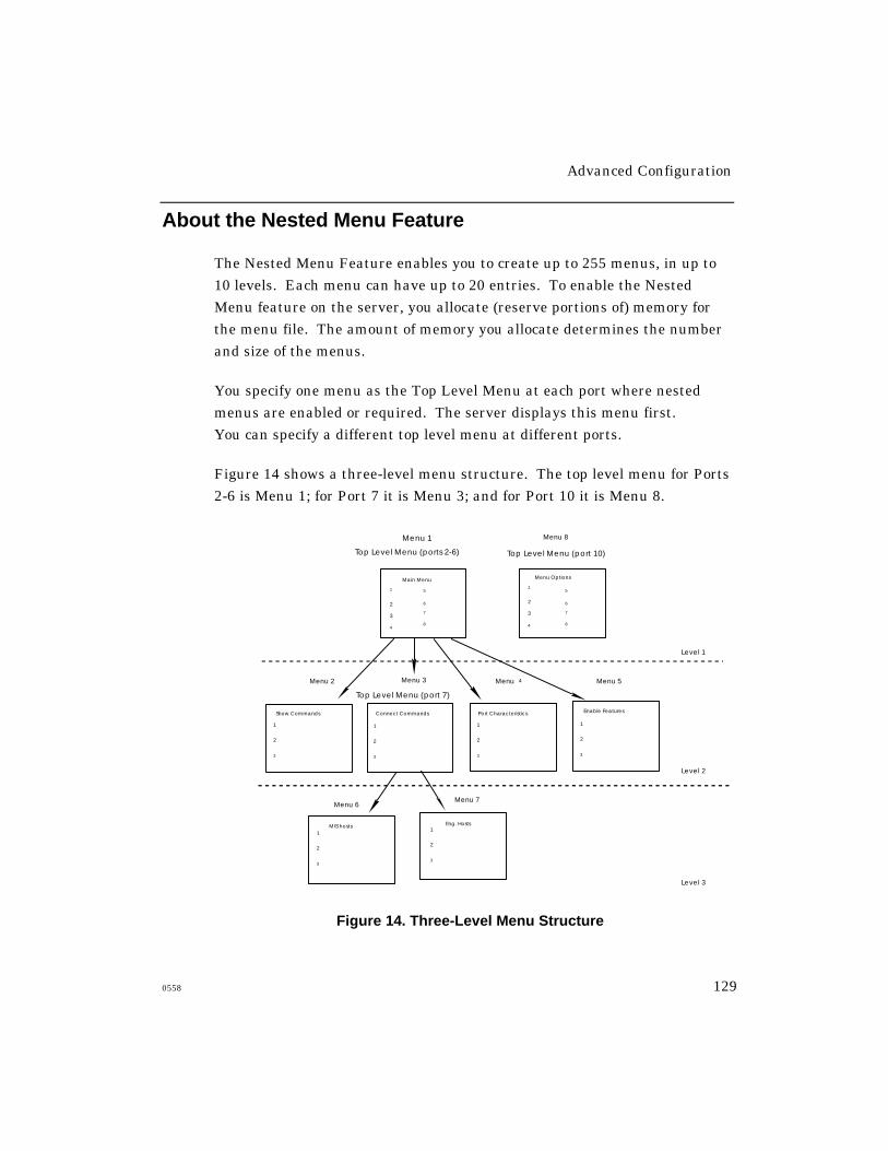
Advanced Configuration
0558 129
About the Nested Menu Feature
The Nested Menu Feature enables you to create up to 255 menus, in up to
10 levels. Each menu can have up to 20 entries. To enable the Nested
Menu feature on the server, you allocate (reserve portions of) memory for
the menu file. The amount of memory you allocate determines the number
and size of the menus.
You specify one menu as the Top Level Menu at each port where nested
menus are enabled or required. The server displays this menu first.
You can specify a different top level menu at different ports.
Figure 14 shows a three-level menu structure. The top level menu for Ports
2-6 is Menu 1; for Port 7 it is Menu 3; and for Port 10 it is Menu 8.
Menu 1
Top Level Menu (ports 2-6)
Menu 4 Menu 5
Menu 6
Menu 2
2
1
3
Menu 3
Level 1
Level 2
Level 3
Top Level Menu (port 7)
2
1
3
Menu 8
Main Menu
1
2
3
4
5
7
8
6
Top Level Menu (port 10)
Show Commands
Menu Options
Port Characteristics
2
1
3
2
1
3
Connect Commands Enable Features
1
2
3
4
5
7
8
6
2
1
3
Menu 7
2
1
3
MIS hosts Eng. Hosts
Figure 14. Three-Level Menu Structure

Advanced Configuration
130 0558
Users at Ports 2-6 have access to Menus 1, 2, 3, 4, 5, 6, and 7, beginning at
Menu 1. Users at Port 7 have access to Menus 3, 6, and 7, beginning at
Menu 3. Users at Port 10 have access to Menu 8 only. The options on
Menus 1 and 3 run Xyplex commands or open other menus. The options on
menus 2, 4, 5, 6, 7, and 8 run commands only.
Figure 15 shows what Menu 1 might look like:
Main Menu
2.
3.
4.
5.
6.
7.
8.
Up one level: ^U Top of Menu:^T Exit Menus: ^E Repaint:^R Logout^L Enter number of selection or use arrow keys:
1. Show Commands
Connect Commands
Port Characteristics
Enable Features Help
Set Session Mode
Disconnect a Session
Resume a Session
Figure 15. Sample Menu
Users can type the characters shown at the bottom of the menu to move up
through the menu levels without choosing options, or to exit from the
menus if the port is also configured to support the command interface.
You define these characters within the menu file. Users can use arrow
keys (↑ and ↓) to move among the entries within a menu.
Advanced Configuration
0558 131
How the Server Obtains the Menu File
When the server boots, it searches for a predefined script server, which
stores the menu file. When it finds the menu file, the server loads it into
local memory. If the server cannot find the menu file, it continues to
operate normally. It logs an error in the Accounting Log if Verbose
accounting is enabled.
How a Port Obtains the Menus
When a user logs on to a port, the server searches the menu file for the top
level menu, and displays that menu on the terminal. The user can then
choose options from the various menus. Commands within the top level
menu determine the sequence of other menus in the file.
If you have not specified a top level menu, or the port cannot find the menu
file, the terminal displays an error message. If nested menus are enabled,
the port reverts to the command interface. If nested menus are required,
the server logs out the port.
A user can go to the command interface from within a menu if Nested
Menus are not required on the port. To do this, the user enters a
predefined Exit key within the menu, or chooses a menu option that
disables the nested menu feature.
Setting Up Script Servers
1. Determine which hosts or access servers will act as script servers.
Script servers must run TFTP. Each access server can have a
maximum of four script servers. You can use two or more hosts as
backup script servers; these can be a combination of script server types.

Advanced Configuration
132 0558
2. Determine where the TFTP process on the UNIX host starts its path
search; this is the TFTP Home directory. Refer to the host’s TFTP
documentation or MAN page.
3. Set up a directory to contain the menu file on each script server.
Create a directory to contain the menu file. On some UNIX systems,
you can create a top-level directory just for the menu file, rather thanusing a directory that already contains many files (e.g., /usr, /bin,
/tftpboot, or /etc .). Systems running with the TFTP secure option
enabled might require you to place the menu file in /tftpboot .
Figure 16 shows how you might set up a directory to contain the menu fileon a UNIX host. In the figure, the file n.menu.file contains the nested
menu commands. The examples that follow show how to create this
directory on a UNIX host and an access server.
/tftpboot
/menus
n.menu.file
Figure 16. Sample Script Server Directory Structure
UNIX Host:
Create the menus directory using lower-case letters:
% mkdir menus
Advanced Configuration
0558 133
Access Server (MAXserver 1820):
Use the MAXserver system disk in a DOS-based PC to create
the directory:
A:> mkdir menus
Specify the location of the script server and the pathname of the menu file,
using the Define/Set Server Script Server commands;
for example:
Xyplex>> define server script server 172.18.12.10 " "
After creating the menu directory and defining the script server, use a text
editor to create the menu file. The next section describes the commands
that you use. The section “Sample Nested Menu Files” includes two
sample menu files.
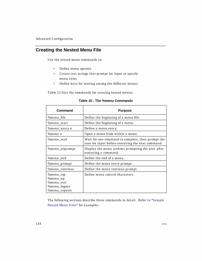
Advanced Configuration
134 0558
Creating the Nested Menu File
Use the nested menu commands to:
• Define menu options
• Create text strings that prompt for input or specify
menu titles
• Define keys for moving among the different menus
Table 15 lists the commands for creating nested menus:
Table 15 - The %menu Commands
Command Purpose
%menu_file Define the beginning of a menu file.
%menu_start Define the beginning of a menu.
%menu_entry n Define a menu entry.
%menu n Open a menu from within a menu.
%menu_wait Wait for one command to complete, then prompt theuser for input before executing the next command.
%menu_noprompt Display the menu without prompting the user afterexecuting a command.
%menu_end Define the end of a menu.
%menu_prompt Define the menu entry prompt.
%menu_continue Define the menu continue prompt.
%menu_top%menu_up%menu_exit%menu_logout%menu_repaint
Define menu control characters.
The following sections describe these commands in detail. Refer to “Sample
Nested Menu Files” for examples.
Advanced Configuration
0558 135
%menu_file
The menu file must begin with %menu_file or the server will not recognize
it as a menu file.
%menu_start n title
This command indicates the beginning of a menu and specifies the menu
number and title.
The value of n is the menu number. Valid values are from 1 through 255.
You use a menu number to specify the top level menu on the server port,through the DEFINE/SET PORT NESTED MENU TOP LEVEL menu-
number command.
The name you specify as the title appears at the top of the menu. The title
can include up to 16 characters.
%menu_entry n entry-description command-string
This command defines a menu option. The value of n is the entry
number for the item on the menu. Follow the option number with a
delimiting character such as a carriage return, line feed, or form feed.
The text of entry-description appears on the menu next to the entry
number. The description can include up to 30 characters. Follow the
description with a delimiting character such as a carriage return, line feed,
or form feed.
The command-string includes one or more Xyplex commands and %menu
commands to be executed when the user chooses the entry number. If a
port has the DECserver-like Interface (DLI) enabled as it does by default
the server interprets the commands in the menu file as part of the DLI
command set.
Advanced Configuration
136 0558
If the port has the UNIX-like interface (ULI) enabled, the interface
interprets the commands in the menu file as part of the ULI command set.
The command-string can include up to 132 characters. If you include more
than one command, separate the commands with a semi-colon (;). For
example, the following command sets the port to Privileged mode, executes
a privileged command, and then resets the port to Nonprivileged mode:
set priv;monitor server status;set nopriv
This example opens the ULI from a DLI port to execute the command alias,
then reopens the DLI:
uli;alias;dli
You can include a wildcard character in a command to prompt for user
input. For example, the command connect # instructs the server to prompt
the user to enter a network destination.
You can also execute a script file in a menu entry command string. Doing
so provides a way of executing a string of commands that exceeds the 132-
character limit of a menu entry. The format for the script command is:
SCRIPT "pathname/script-name"
%menu n
Opens the menu that you specify with the n variable. You can use
this command in the command-string of the %menu_entry command.
%menu_wait
Wait for one command to complete, then prompt the user for input before
executing the next command. This command is useful when you specify two
or more Show/List/Monitor commands in a menu entry. The interface
displays one screen, then waits and prompts for input before displaying
another screen. Use the %menu_continue command to define this prompt.

Advanced Configuration
0558 137
%menu_noprompt
Redisplay the menu after executing commands, without prompting the user
for input.
%menu_end
Indicates the end of a menu. You can begin another menu after this
command appears in the file, or use other menu commands.
%menu_prompt prompt-text
This command specifies a text string that explains how to select a menu
option. This prompt appears at the bottom of the menu where the user
enters an option number. The prompt text can include up to 132
characters. The default prompt text is “Enter Number of Selection or Use
Arrow Keys:”
%menu_continue prompt-text
This command specifies a text string that explains how to redisplay a menu
after a Show/Monitor/List command executes. The prompt text can include
up to 132 characters. The default text is “Press <RETURN> to continue...”
%menu_top x text-string
This command specifies the menu key character that the user types to open
the top level menu. The text-string, which can include up to 20 characters,
describes the purpose of the character. A typical entry might be
%menu_top T Top of Menu. The key and the text appear at the bottom of
the menu. No default exists for this key.
Advanced Configuration
138 0558
%menu_up x text-string
This command specifies the menu key character that the user types to open
a menu one level up. The text-string, which can include up to 20 characters,
describes the purpose of the character. A typical entry might be
%menu_up U Up One Level. The key and the text appear at the bottom
of the menu. No default exists for this key.
%menu_exit x text-string
This command specifies the menu key character that the user types to exit
from the menu interface. If nested menus are enabled at a port, typing this
character recalls the command interface. If nested menus are required at
the port, typing this character logs out the port. The text-string, which can
include up to 20 characters, describes the purpose of the character. A
typical entry might be %menu_exit E Exit Menus. The key and the text
appear at the bottom of the menu. No default exists for this key.
%menu_logout x text-string
This command specifies the menu key character that the user types to log
out of the menu and the server port. The text-string, which can include up
to 20 characters, describes the purpose of the character. A typical entry
might be %menu_logout Q Logout. The key and the text appear at the
bottom of the menu. No default exists for this key.
%menu_repaint x text-string
This command specifies the menu key character that the user types to
refresh the menu screen. The text-string, which can include up to 20
characters, describes the purpose of the character. A typical entry might be
%menu_repaint R Refresh. The key and the text appear at the bottom of
the menu. No default exists for this key.
Advanced Configuration
0558 139
Using Comment Lines in the Menu File
Begin a comment line with an exclamation point (!) and follow it with the
comment text. An example follows:
%menu_end
!start Menu 3. Menu 3 displays CONNECT commands.
%menu_start 3 Connect Commands
The first line specifies the end of a menu. The second line is a comment
explaining that the next section of the file defines a new menu, Menu 3.
The third line is a menu command that begins Menu 3.
General Guidelines
When you create the menu file, observe these guidelines:
• The first line of every menu file is %menu_file.
• You can define menus in any order within the file.
• Each menu must have a menu number.
• You can define menu entries in any order within a menu.
The menu file requires that each menu entry have a number, subject to
these conditions: (1) if the first entry does not have a number, the file
assigns a number to each entry in ascending order, even if subsequent
entries have numbers. (2) if the first entry has a number, all entries in the
menu must have numbers.
The section “Sample Nested Menu Files” shows two sample menu files,
which use all %menu commands.
Advanced Configuration
140 0558
Debugging the Menu File
A syntax error in the menu file prevents the file from executing when a
user attempts to log on to the port. If nested menus are enabled on the port,
the interface displays an error message and opens the command interface.
If nested menus are required on the port, the interface displays the error
message and does not allow the user to log on.
If the Verbose Accounting feature is enabled, the server logs the error and
the line number within the menu file where the error occurred. The Show
Server Accounting display includes this information.
For example, the following entry appears if an error occurs on line 24 of
the file:
12 August 1995 05:30:01 Illegal use of reserved Nested Menu
keyword : line # 24
“Using the Accounting Feature” explains how to enable Verbose Accounting.
Configuring the Server to Support Nested Menus
The following sections explain how to configure the server and individual
ports to use the Nested Menu feature. Refer to this section after you have
created the menu file.
Server Settings
To enable the Nested Menu feature on the server, you must allocate
(reserve portions of) memory for the menu file and specify the menu
filename. After defining these settings, reboot the server.
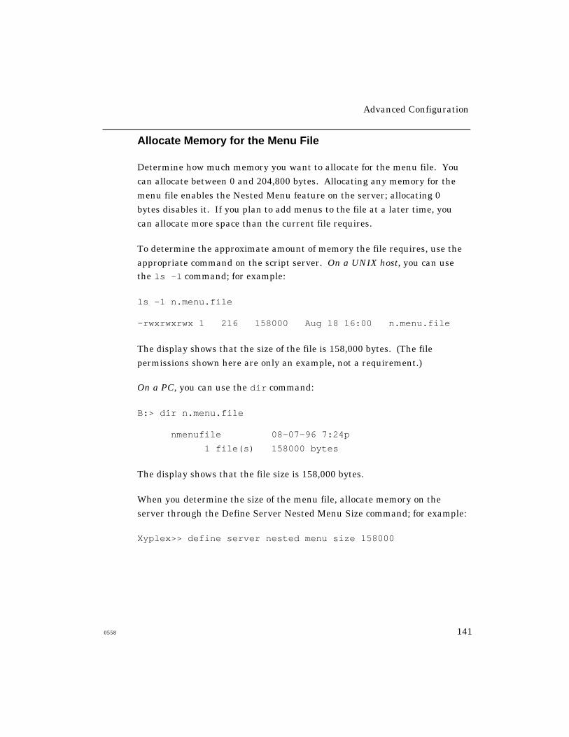
Advanced Configuration
0558 141
Allocate Memory for the Menu File
Determine how much memory you want to allocate for the menu file. You
can allocate between 0 and 204,800 bytes. Allocating any memory for the
menu file enables the Nested Menu feature on the server; allocating 0
bytes disables it. If you plan to add menus to the file at a later time, you
can allocate more space than the current file requires.
To determine the approximate amount of memory the file requires, use the
appropriate command on the script server. On a UNIX host, you can usethe ls -l command; for example:
ls -1 n.menu.file
-rwxrwxrwx 1 216 158000 Aug 18 16:00 n.menu.file
The display shows that the size of the file is 158,000 bytes. (The file
permissions shown here are only an example, not a requirement.)
On a PC, you can use the dir command:
B:> dir n.menu.file
nmenufile 08-07-96 7:24p
1 file(s) 158000 bytes
The display shows that the file size is 158,000 bytes.
When you determine the size of the menu file, allocate memory on the
server through the Define Server Nested Menu Size command; for example:
Xyplex>> define server nested menu size 158000

Advanced Configuration
142 0558
IMPORTANT
After defining the menu file size, specify the name of the file before you
reboot the server. Otherwise, the server cannot determine the name of
the menu file on the script server. (Refer to the following section.)
Specify the Name of the Menu File
Use the Define Server Nested Menu Name command to specify the name of
the menu file on the script server; for example:
Xyplex>> define server nested menu name "n.menu.file"
Wait until the “Storage State” field on the Monitor Server Parameter Server
display goes to “Idle,” then reboot the server:
Xyplex>> init delay 0
Port Settings
Three commands specify Nested Menu port settings. The commands that
specify the status of nested menus and the top level menu are mandatory.
You can optionally enable the Privileged Nested Menu feature.
Specify the Status of the Nested Menus on Ports
You can enable or require Nested Menus in user login scripts or on one or
more ports. Refer to “Using Scripts” for information about creating scripts.
Use the following command to specify the status of Nested Menus at
specified ports. Nested Menus are disabled by default at all ports.
DEFINE/SET PORT port-list NESTED MENU [ENABLED]
[DISABLED]
Example:
Xyplex>> set port 10-15 nested menu enabled
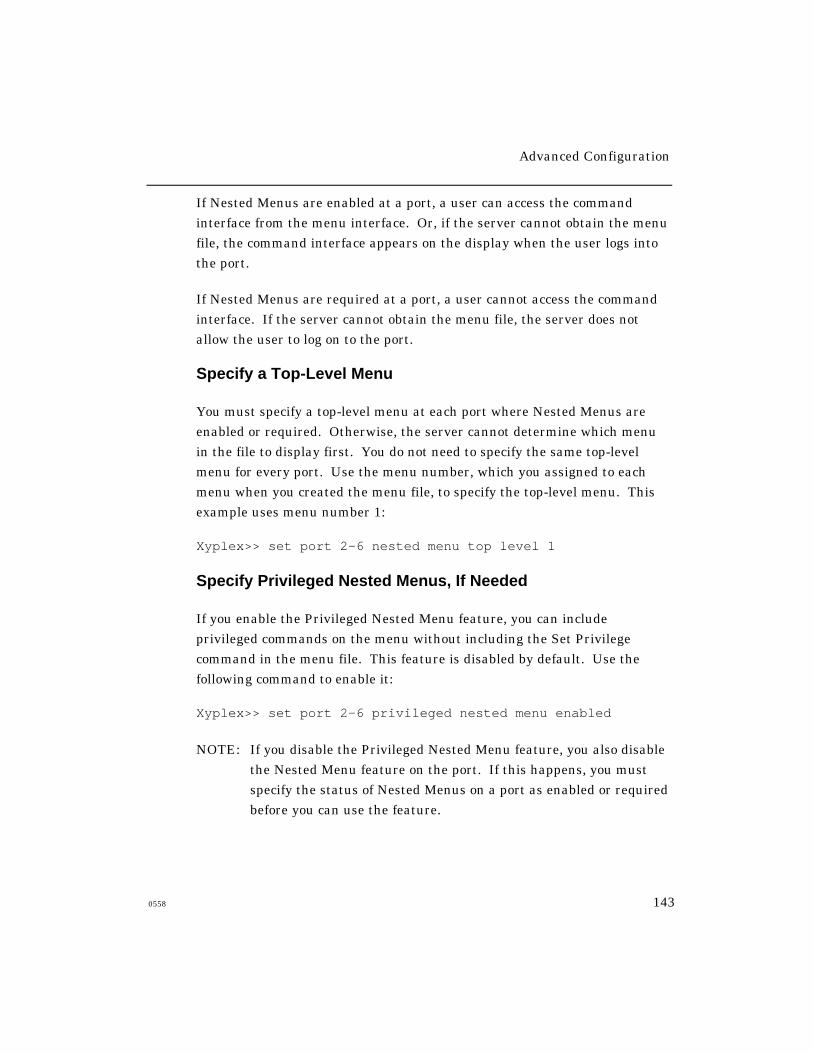
Advanced Configuration
0558 143
If Nested Menus are enabled at a port, a user can access the command
interface from the menu interface. Or, if the server cannot obtain the menu
file, the command interface appears on the display when the user logs into
the port.
If Nested Menus are required at a port, a user cannot access the command
interface. If the server cannot obtain the menu file, the server does not
allow the user to log on to the port.
Specify a Top-Level Menu
You must specify a top-level menu at each port where Nested Menus are
enabled or required. Otherwise, the server cannot determine which menu
in the file to display first. You do not need to specify the same top-level
menu for every port. Use the menu number, which you assigned to each
menu when you created the menu file, to specify the top-level menu. This
example uses menu number 1:
Xyplex>> set port 2-6 nested menu top level 1
Specify Privileged Nested Menus, If Needed
If you enable the Privileged Nested Menu feature, you can include
privileged commands on the menu without including the Set Privilege
command in the menu file. This feature is disabled by default. Use the
following command to enable it:
Xyplex>> set port 2-6 privileged nested menu enabled
NOTE: If you disable the Privileged Nested Menu feature, you also disable
the Nested Menu feature on the port. If this happens, you must
specify the status of Nested Menus on a port as enabled or required
before you can use the feature.

Advanced Configuration
144 0558
Sample Nested Menu Files
Sample File 1 shows a section of a menu file that defines some of the menus
in the 3-level menu structure shown in Figure 14. Sample File 2 shows a
complete nested menu file, without comments. These examples use all
nested menu commands.
Sample File 1
%menu_file Indicates a valid menu file.
!Start Menu 1 - Main Menu Comment line.
%menu_start 1 Main Menu Defines the beginning of menu number 1, andassigns it the title “Main Menu.”
%menu_entry 1 <CR>
Show Commands <CR>
%menu 2
Defines Menu Entry number 1, and assignsthe name “Show Commands” to it. The%menu 2 command instructs the server todisplayMenu 2 when a user selects this entry. The<CR> specifies a carriage return as thedelimiting character after the entry numberand the display text.
%menu_entry 2 <CR>
Connect Commands <CR>
%menu 3
Defines Menu Entry 2, and assigns the name“Connect Commands” to it. The %menu 3command instructs the server to displayMenu 3 when the user selects this entry.
%menu_entry 3 <CR>
Port Settings <CR>
%menu 4
Defines Menu Entry 3, and assigns the name“Port Settings” to it. The %menu 4 commandinstructs the server to display Menu 4 whenthe user selects this entry.

Advanced Configuration
0558 145
%menu_entry 4 <CR>
Enable Features <CR>
%menu 5
Defines menu entry 4, and assigns the name“Enable Features” to it. The %menu 5command instructs the server to displayMenu 5 when the user selects this entry.
%menu_end Indicates the end of Menu 1. You can addmore options to Menu 1 as long as they appearin the file between the %menu_start 1command and the %menu_end command.
!Start Menu 8 - Standalone
MenuComment line
%menu_start 8 Menu Options Defines the beginning of Menu number 8, andassigns it the title “Menu Options.”
%menu_entry 1 <CR>
Change Mode to ANSI <CR>
set port type ANSI;
%menu_noprompt
Defines Menu Entry number 1, and assignsthe name “Change Mode to ANSI” to it. Thecommand line includes the Xyplex commandthat changes the port type, and the menucommand that redisplays the menu withoutprompting the user.
%menu_entry 2 <CR>
Connect to Hosts <CR>
connect #
Defines Menu Entry number 2, and assignsthe name “Connect to Hosts” to it. Thewildcard character # means “prompt for adestination when the user selects this entry.”
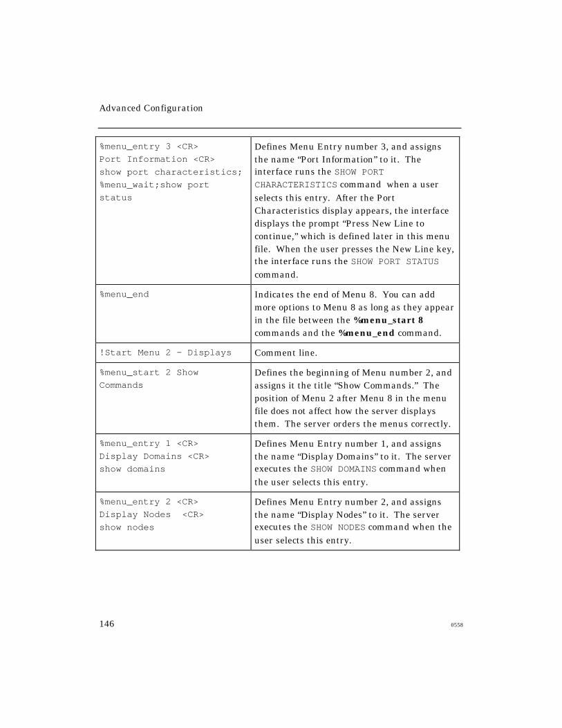
Advanced Configuration
146 0558
%menu_entry 3 <CR>
Port Information <CR>
show port characteristics;
%menu_wait;show port
status
Defines Menu Entry number 3, and assignsthe name “Port Information” to it. Theinterface runs the SHOW PORTCHARACTERISTICS command when a userselects this entry. After the PortCharacteristics display appears, the interfacedisplays the prompt “Press New Line tocontinue,” which is defined later in this menufile. When the user presses the New Line key,the interface runs the SHOW PORT STATUScommand.
%menu_end Indicates the end of Menu 8. You can addmore options to Menu 8 as long as they appearin the file between the %menu_start 8commands and the %menu_end command.
!Start Menu 2 - Displays Comment line.
%menu_start 2 Show
CommandsDefines the beginning of Menu number 2, andassigns it the title “Show Commands.” Theposition of Menu 2 after Menu 8 in the menufile does not affect how the server displaysthem. The server orders the menus correctly.
%menu_entry 1 <CR>
Display Domains <CR>
show domains
Defines Menu Entry number 1, and assignsthe name “Display Domains” to it. The serverexecutes the SHOW DOMAINS command whenthe user selects this entry.
%menu_entry 2 <CR>
Display Nodes <CR>
show nodes
Defines Menu Entry number 2, and assignsthe name “Display Nodes” to it. The serverexecutes the SHOW NODES command when theuser selects this entry.

Advanced Configuration
0558 147
%menu_entry 3 <CR>
Display Port Status <CR>
show port status
Defines Menu Entry number 3, and assignsthe name “Display Port Status” to it. Theserver executes the SHOW PORT STATUScommand when the user selects this entry.
%menu_end Indicates the end of Menu 2. You can addmore options to Menu 2 as long as they appearin the file between the %menu_start 2commands and the %menu_end command.
%menu_prompt
Enter an option number or
use arrow keys.<CR>
Specifies the menu entry prompt.
%menu_continue
Press New Line to
continue. <CR>
Specifies the menu continue prompt.
%menu_up U Up one level Specifies U as the character that a user typesto display the menu that is up one level fromthe current menu.
%menu_top T Top of menu Specifies T as the character that a user typesto open the top level menu.
%menu_logut Q Logout Specifies Q as the character that a user typesto logout of the server port.
%menu_repaint R Repaint Specifies R as the character that a user typesto repaint the screen.
%menu_exit E Exit Menus Specifies E as the character that a user typesto exit from the menu file and use thecommand interface.
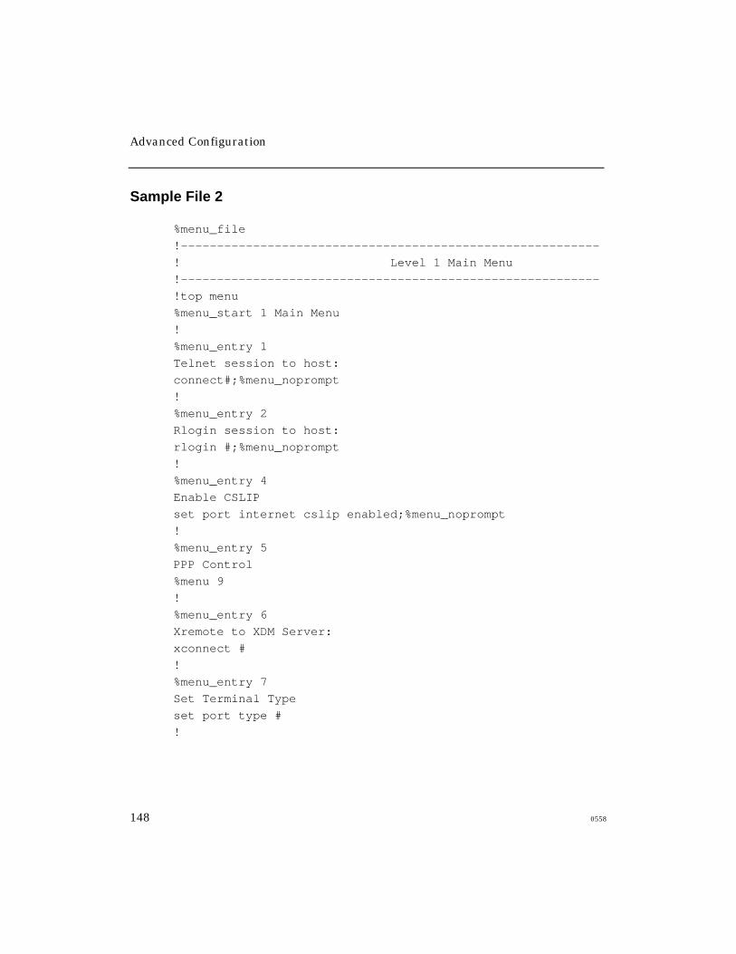
Advanced Configuration
148 0558
Sample File 2
%menu_file
!----------------------------------------------------------
! Level 1 Main Menu
!----------------------------------------------------------
!top menu
%menu_start 1 Main Menu
!
%menu_entry 1
Telnet session to host:
connect#;%menu_noprompt
!
%menu_entry 2
Rlogin session to host:
rlogin #;%menu_noprompt
!
%menu_entry 4
Enable CSLIP
set port internet cslip enabled;%menu_noprompt
!
%menu_entry 5
PPP Control
%menu 9
!
%menu_entry 6
Xremote to XDM Server:
xconnect #
!
%menu_entry 7
Set Terminal Type
set port type #
!

Advanced Configuration
0558 149
%menu_entry 8
Resume a session
sho session;%menu_wait;resume #
!
%menu_entry 9
Disconnect a session
disconnect #
!
%menu_entry 10
ABC UNIX Timesharing
c rcs.abc.edu;%menu_noprompt
!
%menu_entry 11
Port Status
%menu 4
!
%menu_entry 12
Set/Show Port Parameters
%menu 5
!
%menu_entry 13
Set/Show Alt Port Parms
%menu 6
!
%menu_entry 14
Set/Show Telnet Parameters
%menu 7
!
%menu_entry 15
Set/Show TN3270 Parameters
%menu 8
!
%menu_entry 17
Server/Network Tools
%menu 2
!

Advanced Configuration
150 0558
%menu_entry 18
Server Information
%menu 3
!
%menu_entry 20
Exit Menu to CLI
set port nested menu disabled;%menu_noprompt
!
%menu_end
!
!----------------------------------------------------------
! Level 2 Menu 2 Server/Network Tools
!----------------------------------------------------------
!
%menu_start 2 Tools
%menu_entry 1
Ping
set priv system;ping #;set nopriv
%menu_entry 2
Test Pattern
test
%menu_entry 4
Lock Terminal
lock
%menu_entry 5
Send message to port
broadcast #
%menu_entry 6
Show Server Users
sho users
%menu_entry 20
Help
help
%menu_end

Advanced Configuration
0558 151
!
!----------------------------------------------------------
! Level 2 Menu 3 Server Information
!----------------------------------------------------------
!
%menu_start 3 Server Information
%menu_entry 1
Main Parameters
show server
%menu_entry 2
Current Status
show server status
%menu_entry 3
Network Statistics
show server counters
%menu_entry 4
Domain Information
set priv system;show domain;set nopriv
%menu_entry 5
IP Information
show server internet
%menu_entry 11
Show Users
show users
%menu_entry 12
Arp Cache
uli;arp -a;dli
%menu_entry 13
Summary
show server summary
%menu_entry 14
Alternate Status
show server alternate status
%menu_entry 15
Routing Tables
show server ip route

Advanced Configuration
152 0558
%menu_entry 20
Help
help
%menu_end
!----------------------------------------------------------
! Level 2 Menu 4 Port Status
!----------------------------------------------------------
!
%menu_start 4 Port Status
%menu_entry 1
Show Port Summary
show port summary
%menu_entry 2
counters
show port counters
%menu_entry 3
Status
show port status
%menu_entry 4
Sessions
show sessions
%menu_entry 11
Show Users
show users
%menu_entry 20
Help
help
%menu_end
!

Advanced Configuration
0558 153
!----------------------------------------------------------
! Level 2 Menu 5 Set/Show Port Parameters
!----------------------------------------------------------
!
%menu_start 5 Port Parameters
%menu_entry 1
Show port Parameters
show port characteristics
%menu_entry 3
Set Terminal Type = Hardcopy
set port type hardcopy;%menu_noprompt
%menu_entry 4
Set Terminal Type = Dumb
set port type soft;%menu_noprompt
%menu_entry 5
Set Terminal Type = VT100
set port type ansi;%menu_noprompt
%menu_entry 6
Set Switch to Command Mode chr
set port local #
%menu_entry 13
Set Session Forward Switch chr
set port forward #
%menu_entry 14
Set Session Backwrd Switch chr
set port back #
%menu entry 15
Set char length (7-8)
set port cha #
%menu_entry 16
Set Parity
set port parity #
%menu_entry 20
Help
help
%menu_end
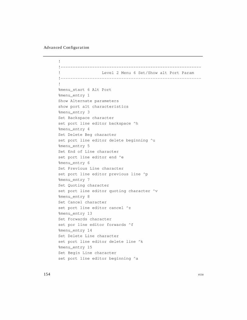
Advanced Configuration
154 0558
!
!----------------------------------------------------------
! Level 2 Menu 6 Set/Show alt Port Param
!----------------------------------------------------------
!
%menu_start 6 Alt Port
%menu_entry 1
Show Alternate parameters
show port alt characteristics
%menu_entry 3
Set Backspace character
set port line editor backspace ^h
%menu_entry 4
Set Delete Beg character
set port line editor delete beginning ^u
%menu_entry 5
Set End of Line character
set port line editor end ^e
%menu_entry 6
Set Previous Line character
set port line editor previous line ^p
%menu_entry 7
Set Quoting character
set port line editor quoting character ^v
%menu_entry 8
Set Cancel character
set port line editor cancel ^z
%menu_entry 13
Set Forwards character
set por line editor forwards ^f
%menu_entry 14
Set Delete Line character
set port line editor delete line ^k
%menu_entry 15
Set Begin Line character
set port line editor beginning ^a
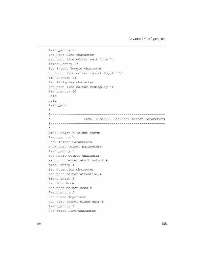
Advanced Configuration
0558 155
%menu_entry 16
Set Next Line character
set port line editor next line ^n
%%menu_entry 17
Set Insert Toggle character
set port line editor insert toggle ^w
%menu_entry 18
Set Redisplay character
set port line editor redisplay ^r
%menu_entry 20
Help
help
%menu_end
!
!----------------------------------------------------------
! Level 2 menu 7 Set/Show Telnet Parameters
!----------------------------------------------------------
!
%menu_start 7 Telnet Parms
%menu_entry 1
Show Telnet Parameters
show port telnet parameters
%menu_entry 3
Set Abort Output character
set port telnet abort output #
%menu_entry 4
Set Attention character
set port telnet attention #
%menu_entry 5
Set Echo Mode
set port telnet echo #
%menu_entry 6
Set Erase Keystroke
set port telnet erase char #
%menu_entry 7
Set Erase Line Character

Advanced Configuration
156 0558
set port telnet erase line #
%menu_entry 8
Set Terminaltype
set port telnet terminaltype #
%menu_entry 9
Set TN3270 TranslationTable
set port telnet TN3270 trans #
%menu_entry 13
Set Newline Filtering
set port telnet newline filtering #
%menu_entry 14
Set Query character
set port telnet query char #
%menu_entry 15
Set Remote Port
set port telnet remote #
%menu_entry 16
Set Synchronize character
set port telnet synch #
%menu_entry 17
Set Transmit Mode
set port telnet transmit #
%menu_entry 18
Set Session Mode
set port telnet binary session mode #
%menu_entry 19
Set TN3270 Device
set port telnet TN3270 device #
%menu_entry 20
Help
help
%menu_end
!
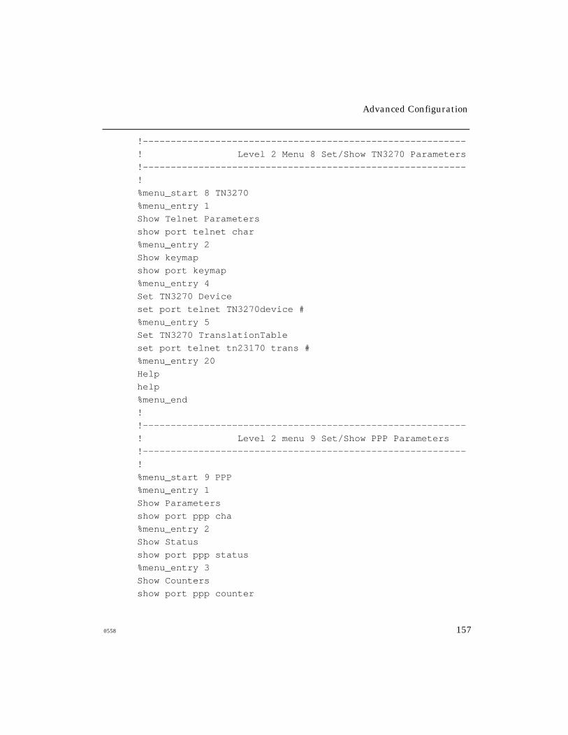
Advanced Configuration
0558 157
!----------------------------------------------------------
! Level 2 Menu 8 Set/Show TN3270 Parameters
!----------------------------------------------------------
!
%menu_start 8 TN3270
%menu_entry 1
Show Telnet Parameters
show port telnet char
%menu_entry 2
Show keymap
show port keymap
%menu_entry 4
Set TN3270 Device
set port telnet TN3270device #
%menu_entry 5
Set TN3270 TranslationTable
set port telnet tn23170 trans #
%menu_entry 20
Help
help
%menu_end
!
!----------------------------------------------------------
! Level 2 menu 9 Set/Show PPP Parameters
!----------------------------------------------------------
!
%menu_start 9 PPP
%menu_entry 1
Show Parameters
show port ppp cha
%menu_entry 2
Show Status
show port ppp status
%menu_entry 3
Show Counters
show port ppp counter
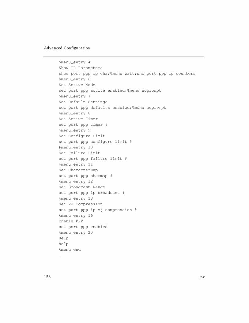
Advanced Configuration
158 0558
%menu_entry 4
Show IP Parameters
show port ppp ip cha;%menu_wait;sho port ppp ip counters
%menu_entry 6
Set Active Mode
set port ppp active enabled;%menu_noprompt
%menu_entry 7
Set Default Settings
set port ppp defaults enabled;%menu_noprompt
%menu_entry 8
Set Active Timer
set port ppp timer #
%menu_entry 9
Set Configure Limit
set port ppp configure limit #
#menu_entry 10
Set Failure Limit
set port ppp failure limit #
%menu_entry 11
Set CharacterMap
set port ppp charmap #
%menu_entry 12
Set Broadcast Range
set port ppp ip broadcast #
%menu_entry 13
Set VJ Compression
set port ppp ip vj compression #
%menu_entry 16
Enable PPP
set port ppp enabled
%menu_entry 20
Help
help
%menu_end
!
Advanced Configuration
0558 159
!----------------------------------------------------------
! On the Level - Misc Parameters
!----------------------------------------------------------
!
%menu_top t Top Menu
%menu_up u Up a Menu Level
%menu_logout x Logout
%menu_repaint r Refresh
%menu_continue
CR to continue...
Using Scripts
The Network Command Script feature enables you to create a script file
that contains one or more commands, and to store the file on a host
computer called a script server. You can configure an access server port to
request the script file and execute the commands in it as soon as a user logs
on to the port; or, you can allow the user to request the script file.
You use a text editor to create script files on the script server. The script
server can be a host system that supports the Trivial File Transfer Protocol
(TFTP) or a Xyplex device that can load files over a network.
This section explains how to use the script feature, how to create scripts on
a script server, and how to set up the access server to use scripts.
• How the Script Feature Works
• Setting Up the Script Server
• Setting Up the Access Server to Use Scripts
• Sample Scripts

Advanced Configuration
160 0558
How the Script Feature Works
When a user logs on to an appropriately configured port, the server requests
a script file for that user from each available script server. If the script is
available at more than one script server, it obtains the file from the first
script server that responds. If no script file for a given user is found, the
server searches for a generic script file. Upon receiving the complete script
file, the access server executes the commands within the file and completes
the login sequence. You can configure ports to require a script file in order
to complete the login sequence, or to log out the user after a suitable
waiting period if a file cannot be found.
If the port is a “dialback” modem port, you can also create a separate
dialback script. This script specifies the telephone number to dial when a
specific user attempts to log on to the server through a modem. If the
access server cannot find a script file for that user, it will not allow the user
to log in. If it does find a script file for the user, the server instructs the
modem to dial the user back at a designated telephone number. You can
use the dialback script together with a login script for dialback ports.
The network command script feature provides great flexibility to users and
to the access server manager:
• It allows users to “transport” their port configuration. This is
especially useful when configuring a port with special attributes; for
example, special TN3270 keyboard mapping.
• Network managers can reboot access servers with a single
command, and use system set-up scripts which can include
welcome messages from a central location.
Advanced Configuration
0558 161
• It provides a method of login control and security. For example, you
can configure a port to execute the script when a user attempts to
log on. If the user enters an incorrect username, the port will not
find the script, and consequently will not log on the user.
• The command script feature is particularly useful for controlling
connections made through modems, since the software uses the
network command script feature to support dialback operations.
Setting Up the Script Server
Follow these steps:
1. Determine which UNIX hosts or Xyplex Access Servers are to serve
as script servers. Each access server can have up to four script
servers. You can use two or more hosts as backup script servers;
these can be a combination of dial-back or login script servers.
2. Set up directories to contain script files on each script server. For a
UNIX-based script server, you must follow the TFTP guidelines in the
section “Directory Requirements”.
a) For each user who needs a custom login or dialback script file,
create a directory to contain the files. The directory name must
match the name that the user enters when logging on to the port (atthe Enter username> prompt). At a script server, all username
directories must be located in the same top-level directory. For ease
of use, you can create a top-level directory for script files only,
rather than using a directory that already contains many files, suchas /usr, /bin, /tftpboot, or /etc on a UNIX host.
b) If two or more users share a single script, you do not need to create
individual directories for them. You can store the script in a
common directory. To use a combination of custom and common
script files, place custom files in the individual user directories,
and place the common file in the top-level directory.
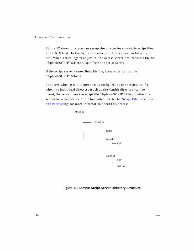
Advanced Configuration
162 0558
Figure 17 shows how you can set up the directories to contain script files
at a UNIX host. In the figure, the user jsmith has a custom login script
file. When a user logs in as jsmith, the access server first requests the file
/tftpboot/SCRIPTS/jsmith/login from the script server.
If the script server cannot find this file, it searches for the file
/tftpboot/SCRIPTS/login.
For users who log in at a port that is configured to use scripts, but for
whom no individual directory (such as the /jsmith directory) can be
found, the server uses the script file /tftpboot/SCRIPTS/login, after the
search for a custom script file has failed. Refer to “Script File Execution
and Processing” for more information about this process.
/tftpboot
/SCRIPTS
login
/jsmith
login
/gjones
login
dialback
Figure 17. Sample Script Server Directory Structure
Advanced Configuration
0558 163
The user “gjones” has both a login script file and a dialback script file. The
dialback script contains information that tells the modem which telephone
number to dial when a user named gjones attempts to log on to the server
through a modem. If gjones’ modem answers when dialed, the user goes
through the login routine, and the login script is also run.
Note that if a user logs in as gjones to a non-dialback port that is configured
to use a login script, the script server sends the file
/tftpboot/SCRIPTS/gjones/login to be run at the port.
In order for the server to locate a user’s custom script file, the port username
must match the directory name at the host. Therefore, to use their custom
login scripts, users must type the correct username when logging in.
For example, to create a top-level directory named SCRIPTS, and a
username directory for a user whose login name is “jsmith”, you would type
the following commands:
UNIX Host
% mkdir SCRIPTS
% cd SCRIPTS
% mkdir jsmith
% cd jsmith
MAXserver 1820
Take the MAXserver system disk to a DOS-based personal computer
(PC) to create a directory for each user. For example:
B:> mkdir SCRIPTS
B:> cd SCRIPTS
B:> mkdir jsmith
B:> cd jsmith
For additional users, the directory for each username would be a
subdirectory of the SCRIPTS directory.

Advanced Configuration
164 0558
Create the Script File
At the UNIX host or PC, use a text editor to create the script file. Use the
name “login” for script files that run when a user logs on to a port. Use the
name “dialback” for script files that contain dialback instructions. At a
UNIX host, the filename must consist of all lower-case letters.
Follow the guidelines in the next section when developing a script file. The
section “Sample Scripts” shows examples.
Writing the Script
Observe the following rules when writing a script:
• The first line in the script file must begin with #control_script on the
first column of the line.
• You can use most access server commands in a script. Use the same
command syntax that you would enter with the command interface.
Exceptions: You cannot run another script file within a script file
(“nested” scripts are not allowed). You cannot specify menu commands
within a script file.
• You can include commands that require user input, such as commands
that require a password. The access server will prompt the user for the
password or other input before continuing. The interface displays the
user prompt regardless of the setting of the Port Script Echo
characteristic.
• You can set a port to privileged mode in two ways: (1) by including theSET PRIVILEGE command and displaying the privilege password
prompt to the user. When the user enters the correct password, the
port becomes privileged. (2) by including a line in the form:
set priv privilege-password
Advanced Configuration
0558 165
The command set priv must be in lower case letters; begin on column
1 of the script file; and contain exactly one space between the
keywords set and priv. Note that the set priv command and
privileged-password are not displayed, even if the Port Script Echo
setting is enabled.
• Each line of a script file can contain only one command with up to 132
characters. Each command must be on one line.
• You can include a Connect command in a script file. For clarity,
Xyplex recommends that you include Connect commands at the end of
the script file.
NOTE: When using edlin to create a script file for use on an
MX-1800/1820 diskette, note that the default end-of-file, or
EOF indicator (^Z or A1) causes a syntax error when the script
executes. When you write the script file to the diskette, delete
the EOF indicator from the file.

Advanced Configuration
166 0558
The # Character
Within command scripts, the access server recognizes the pound (#)
character as a flag for special operations. When the pound character is the
first character on a command line, the server attempts to treat the contents
of the line as control information, which it must interpret. When the #
character is followed by a anything other than a script keyword, it indicates
a comment. The server ignores the remainder of the line.
# echo
When the word “echo” follows the # character, it indicates that a text
message or a blank line is to be displayed to the user. The access server
displays all characters after #echo when the user executes a script. For
example, the text-string in the following line appears on the terminal screen
when the user executes the script.
#echo text-string
The phrase #echo must be in lower case letters. The text-string is displayed
to the user, even if the Port Script Echo setting is disabled. If the text-string
consists of one or more spaces, a blank line is displayed to the user.
# modem
When the word modem follows the # character in a dialback script, it
specifies a modem command that the server must pass on to a modem. The
phrase #modem must be in lower case letters. All white space following
#modem is removed before the server passes the text on to the modem.
# pause
When the word pause follows the # character, it causes the script to pause
its execution for a specified number of seconds. This feature is useful in
dialback scripts. The following command line causes the script to pause for
five seconds:
#pause 5
Advanced Configuration
0558 167
# privileged
NOTE: Do not abbreviate this keyword in the script.
When the word privileged follows the # character in a dialback
script, it allows the access server to execute privileged commands in
a script file on a port that does not have Privileged mode set. This
keyword is useful when you want to execute privileged commands in
a script, but you do not want to include the privileged password in
the script. When a script includes this keyword, the access server
executes any subsequent privileged commands. When the script
execution completes, the port reverts to the privilege level that was
enabled prior to the script execution.
Directory Requirements
The script server downloads files to the access server through TFTP.
Typically, UNIX systems require that you store all files to be transferred via
TFTP in the TFTP “home directory.” Most UNIX systems provide a
mechanism for specifying the TFTP home directory, or a default home
directory. The default TFTP home directory varies from system to system.
Follow the configuration instructions for the TFTP daemon (tftpd) in your
UNIX system’s documentation (e.g., MAN pages), to determine how to
locate the TFTP home directory.
For example, on Sun Workstations, the MAN page for tftpd says that the
home directory is defined in the /etc/inetd.conf file, and that the factory
default home directory is /tftpboot. Therefore, you would check the tftp
entry in the /etc/inetd.conf file to see if the system is using the default home
directory or a user-specified home directory. Place the script files in the
home directory.

Advanced Configuration
168 0558
Using a Link
To simplify configuration, such as adding users, or to prevent the TFTP
home directory from becoming cluttered, you can place script files in a
directory other than the TFTP home directory. To do this, create a link
from the directory containing the script files to the TFTP home directory,
so that the TFTP daemon knows where to locate the files. Give the link
suitable file permissions using commands in this form (note that you must
be superuser):
# cd tftp-home-directory
# ln -s script-directory-path script-directory-name
# chmod 777 script-directory-name
For example, on Sun Workstations, using the default TFTP home
directory, /tftpboot, and a directory named /SCRIPTS as the top-level
directory in which script files are stored, you would use these
commands:
# cd /tftpboot
# ln -s /SCRIPTS
# chmod 777 /tftpboot
TFTP Security Mechanisms
Your UNIX system might have TFTP security mechanisms that limit
TFTP to specific directories. For example, SunOS uses a TFTP daemon -s
(for secure) option that restricts TFTP access to a specific directory and its
subdirectories. Sun Workstations are normally configured with this option
enabled. An entry similar to -s /tftpboot in the tftpd entry appears in the
/etc/inetd.conf file. Read the MAN pages for tftp, tftpd, and inetd.conf to
determine the directory/security requirements on your UNIX system.

Advanced Configuration
0558 169
Setting Up the Access Server to Use Scripts
Specify the locations where the access server can request script files, using
an IP address or domain name, and the directory locations where the files
reside. Also specify which ports use or require a script file for login.
1. Make sure that Telnet is enabled, and that you have defined the
server’s IP address. Also make sure that you have defined the address
of the domain name server, if the server accesses the script server
through a domain name.
2. Define one or more script servers:
DEFINE/SET SERVER SCRIPT SERVER [domain-name “directory-path”]
[ip-address “directory-path”]
Note that you must define a path even if the script resides in the default
directory, /tftpboot. When this is the case, specify the null path, “ “.
Examples:
Xyplex>> define server script server host.xyplex.com " "
Xyplex>> define server script server host.xyplex.com
"scripts"
Xyplex>> define server script server 192.168.19.101
"scripts"
You can define up to four script servers.
3. Where applicable, specify whether the ports require the access server to
download and execute the script in order to complete the login sequence.
If the port requires the script at login time, it will not complete the login
sequence if the access server cannot find the script.
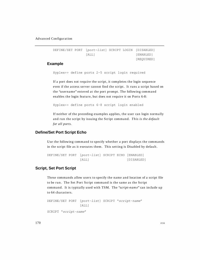
Advanced Configuration
170 0558
DEFINE/SET PORT [port-list] SCRIPT LOGIN [DISABLED]
[ALL] [ENABLED]
[REQUIRED]
Example
Xyplex>> define ports 2-5 script login required
If a port does not require the script, it completes the login sequence
even if the access server cannot find the script. It runs a script based on
the “username” entered at the port prompt. The following command
enables the login feature, but does not require it on Ports 6-8:
Xyplex>> define ports 6-8 script login enabled
If neither of the preceding examples applies, the user can login normally
and run the script by issuing the Script command. This is the default
for all ports.
Define/Set Port Script Echo
Use the following command to specify whether a port displays the commands
in the script file as it executes them. This setting is Disabled by default.
DEFINE/SET PORT [port-list] SCRIPT ECHO [ENABLED]
[ALL] [DISABLED]
Script, Set Port Script
These commands allow users to specify the name and location of a script file
to be run. The Set Port Script command is the same as the Script
command. It is typically used with TSM. The “script-name” can include up
to 64 characters.
DEFINE/SET PORT [port-list] SCRIPT “script-name”
[ALL]
SCRIPT “script-name”
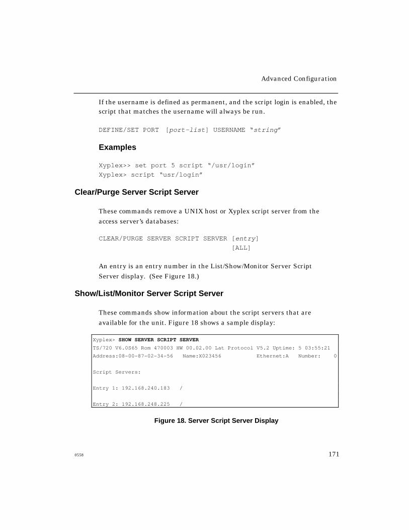
Advanced Configuration
0558 171
If the username is defined as permanent, and the script login is enabled, thescript that matches the username will always be run.
DEFINE/SET PORT [port-list] USERNAME “string”
Examples
Xyplex>> set port 5 script “/usr/login”
Xyplex> script “usr/login”
Clear/Purge Server Script Server
These commands remove a UNIX host or Xyplex script server from the
access server’s databases:
CLEAR/PURGE SERVER SCRIPT SERVER [entry]
[ALL]
An entry is an entry number in the List/Show/Monitor Server Script
Server display. (See Figure 18.)
Show/List/Monitor Server Script Server
These commands show information about the script servers that are
available for the unit. Figure 18 shows a sample display:
Xyplex> SHOW SERVER SCRIPT SERVER
TS/720 V6.0S65 Rom 470003 HW 00.02.00 Lat Protocol V5.2 Uptime: 5 03:55:21
Address:08-00-87-02-34-56 Name:X023456 Ethernet:A Number: 0
Script Servers:
Entry 1: 192.168.240.183 /
Entry 2: 192.168.248.225 /
Figure 18. Server Script Server Display

Advanced Configuration
172 0558
Script File Execution and Processing
The access server runs a script when a user logs on to a port, or when a
user issues the Script command. The following events occur when the
server runs the script file:
1. The user attempts to log on to a port where the Script Login setting
is either Enabled or Required. The user enters a login username
when the Enter username> prompt appears.
If the port is configured for dialback, the connection is immediately
broken. The server saves the port username in order to locate the
script file and authenticate the user and also saves the port speed.
2. The server makes a request to the TFTP process (e.g., a UNIX TFTP
daemon) at each script server, to download a specific script file. The
file to be downloaded is determined by the server, as follows:
• If the script is being run when a user logs on to a server port, the
access server requests a script file named login from a directory
location that is based on two items: (1) the pathname specified in
the Define/Set Server Script Server command and (2) the username
of the port, with blank spaces removed. The Define/Set Server
Script Server command designates the top-level directories to be
searched. An example follows:
Xyplex>> define server script server 192.168.11.101
“scripts”
If a user named “John A. Smith” logs on to a port, the server
requests the script file /usr/xyplex/JohnA.Smith/login from the
script server at address 192.168.11.101.
If the TFTP process does not find the script at the specified location,
it searches the directory immediately above the specified one.
Advanced Configuration
0558 173
• If the script is being run as the result of a user request, the name
and location of the script file is supplied by the user in the Script or
Set Port Script command. If the user does not specify a script to be
run, the server requests the script that would normally be used at
port login.
• If the script is being run at a dialback port, the server requests a
script file named dialback. The directory location at the script
server is the same as for a login script.
• If the requested file is found at a script server within 30 seconds, the
script server downloads the script file to the server through TFTP.
• If the requested file is not found at any script server within 30
seconds, the action that the server takes depends on the value of the
Port Script Login setting and, for dialback ports, the value of the
Port Dialback setting.
• If the Port Script Login setting is set to Required, the server logs out
the port. If it is set to Enabled, the port is logged on.
• If the Port Dialback setting is set to Enabled, the server logs out
the port.
3. After the requested script file is found at the script server, the file is
completely read into memory by the access server, before it is run.
• When a script file contains a Connect command, the access server
initiates the command, runs the remaining commands within the
script, and logs on the port. After script finishes running, the
access server completes the Connect command.
Advanced Configuration
174 0558
• A dialback port passes the dialing information to the modem, which
then dials the remote modem. The remote modem has only a
limited time in which to respond (based on the Port Dialback
Timeout setting). If the remote modem does not respond within this
interval, or if the line is busy, the server logs out the port and drops
the connection. If the remote modem responds within the required
interval, the server begins the normal login sequence.
When the Enter username> prompt appears again, the user must
type the same name that he typed originally (in Step 1) or the port
is logged out and the connection is dropped. If the port is set up to
use or require a login script, the server requests and runs the script.
• You can use Kerberos and other security features to provide
additional security.
Sample Scripts
1. This login script temporarily defines a dedicated service. You might set
up this script for a user who has only limited experience with the access
server. The script automatically sets Privileged mode so that the Define
command can run; it then resets the mode to Nonprivileged.
#control_script
# This script enforces a dedicated service
#PRIV
DEFINE PORT TELNET DEDICATED SERVICE FINANCESUN
SET NOPRIV
2. This login script defines TN3270 settings. It enables a user to “carry”
the settings to other ports. The script requires the user to enter the
privileged password.
#control_script
# Use this script to set up a access server for TN3270.
Advanced Configuration
0558 175
# TN3270 protocol must be enabled on the access server.
#
# Set up TN3270 port characteristics.
#PRIV
SET PORT TELNET TN3270 DEVICE VT100
SET SERVER IP PRIMARY GATEWAY ADDRESS 192.168.1.1
SET DOMAIN VMS 192.168.1.101
SET NOPRIV
CONNECT VMS
3. This dialback script contains dialing information for a modem:
#control_script
# This is a dialback script.
#modem atdt5551978
#pause 3
#modem atdt33
4. This login script displays a system welcome message. The script uses
the echo feature and a control character in an echo line.
#control_script
#echo welcome to Company X <Bel>
#echo
#echo The laser printer is down today.
Using the Accounting Feature
This section explains how to use the Accounting feature. It covers the
following topics:
• Enabling the accounting feature
• Enabling the syslogd daemon
• Information in the Account Log
• Associated commands

Advanced Configuration
176 0558
When the Accounting feature is enabled, the access server records
information about successful and attempted connections made to or from its
ports, as well as information about disconnected sessions. It stores this
information in a log file.
The following accounting features require that the access server have at
least 2 MB of memory and be running appropriate software:
• syslogd daemon
• Verbose Accounting mode
• Verbose Priority number
• Clear Server Accounting command.
The load images for Network 9000 Access Server 720 modules and
MAXserver 1620/1640 access servers support all these features. Refer to
the Access Server Software Release Notes for information about the
appropriate load images for other access server types.
Enabling the Accounting Feature
Complete these steps:
1. Log on to an access server port and set privileged mode.
2. Specify the maximum number of accounting entries that the access
server may store. This enables the accounting feature. For example,
the following command specifies a maximum of 1000 accounting entries
and enables the accounting feature:
Xyplex>> define server accounting entries 1000
The server displays a message (number 705 or 708) that indicates how
many bytes of memory remain after the feature is enabled, or which are
needed to enable the feature.
Specifying 0 entries disables the Accounting feature.
Advanced Configuration
0558 177
3. Reboot the access server. You can either push the Reset button on the
front of the access server or enter the following command:
Xyplex>> init delay 0
4. To verify that Accounting is enabled after the access server boots, check
the Show Server Characteristics display.
Enabling the syslogd Daemon
You can use the syslogd daemon to log accounting information to a
remote UNIX host. The daemon supports both normal and verbose
accounting entries.
As the access server logs accounting entries, it sends a message to the
UNIX host that you specify in the command line. The syslogd daemon
intercepts the message and routes it to one or more destinations,
depending on the settings in the /etc/syslog.conf file on the host. For
example, the host might display output on a console screen, or write the
information to a log file.
To change the status of syslogd, use the Define Server Daemon Syslogd
Enabled/Disabled command. The setting is disabled by default. When you
enable it, you must specify the IP address of the host where the remote
account log is to reside:
Xyplex>> define server daemon syslogd enabled 172.19.24.81
Reboot the access server for the command to take effect. When you disable
the daemon, you do not need to specify an IP address.

Advanced Configuration
178 0558
Defining Two syslogd Hosts on the Access Server
You can now define up to two Syslogd hosts for logging of information.
Please note the following whenever you define a Syslog host:
• Host 1 must be defined first
• A unique IP address must be defined for each Syslogd host
• Syslog messages for both hosts must be logged at the same Log Facility
• To delete a Syslogd host, you must first disable Host 2
Use the following command to define the Syslog hosts:
For Host 1, use:
DEFINE SERVER DAEMON SYSLOGD ENABLED HOST1<ip-address-syslogd-host1>
For Host 2, use:
DEFINE SERVER DAEMON SYSLOGD ENABLED HOST2 <ip-address-of-syslogd-host2>
To display Syslogd host, use the following command:
SHOW UNIT
Both Syslogd hosts display if they have been previously defined.
NOTE: If you are upgrading from an earlier revision and already have a
Syslogd host defined, then the SHOW UNIT display will now show
that host as “Host1” as opposed to “Host.”

Advanced Configuration
0558 179
Information In the Account Log
The access server can store information in two types of account log:
• Default account log
• Verbose account log
The default log is enabled automatically when you enable the accounting
feature. You enable verbose accounting through a separate command.
The Default Account Log
The default account log records the following information:
• The port numbers where connections were made or attempted
• The usernames of ports
• The sources of the connections, whether local or remote, and the
network protocols that the connections used
• The destinations of the connections
• The time when connections were first made
• The times when connections were terminated
• The reasons why sessions were terminated
• The amount of data received from the connected devices
• The amount of data sent by ports to the connected devices

Advanced Configuration
180 0558
You can use this information for purposes such as:
• Identifying when and where a connection attempt occurred. This
information can help determine if your network has a security
problem, such as “hackers” attempting to log in.
• Identifying why the access server is rejecting connections, for
troubleshooting purposes.
• Providing a record for “billing” time or services. This use requires a
host-based application that can collect and store the accounting
information from the server.
The access server can store up to 1000 session accounting entries. When
the account log reaches its maximum size, the server discards the oldest
entry each time it logs a new one. Depending on the number of entries in
the log file, the accounting feature can use up to 210 KB of memory as it
does in a log file containing 1000 entries.
Memory Considerations
Before you enable this feature, be sure that the access server has adequate
memory to support the accounting log. Some access servers have limited
memory available. Enabling the feature on these servers limits the number
of other features that you can use. Similarly, enabling other features can
affect the amount of memory available for the Accounting feature.
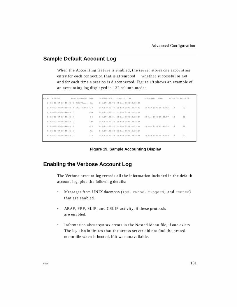
Advanced Configuration
0558 181
Sample Default Account Log
When the Accounting feature is enabled, the server stores one accounting
entry for each connection that is attempted whether successful or not and for each time a session is disconnected. Figure 19 shows an example of
an accounting log displayed in 132 column mode:
ENTRY ADDRESS PORT USERNAME TYPE DESTINATION CONNECT TIME DISCONNECT TIME BYTES IN BYTES OUT
1 08-00-87-00-4F-45 8 TN3270user -Lte 140.179.80.75 25 May 1996 15:38:33
1 08-00-87-00-4F-45 8 TN3270user -D 0 140.179.80.75 25 May 1996 15:38:33 25 May 1996 15:40:55 13 92
2 08-00-87-00-4F-45 1 -Lte 140.179.80.31 25 May 1996 15:39:54
2 08-00-87-00-4F-45 1 -D 0 140.179.80.31 25 May 1996 15:39:54 25 May 1996 15:40:57 13 92
3 08-00-87-00-4F-45 2 -Lte 140.179.80.32 25 May 1996 15:39:54
3 08-00-87-00-4F-45 2 -D 0 140.179.80.32 25 May 1996 15:39:54 25 May 1996 15:40:58 13 92
4 08-00-87-00-4F-45 3 -Rte 140.179.80.33 25 May 1996 15:39:54
4 08-00-87-00-4F-45 3 -D 0 140.179.80.33 25 May 1996 15:39:54 25 May 1996 15:40:59 15 92
Figure 19. Sample Accounting Display
Enabling the Verbose Account Log
The Verbose account log records all the information included in the default
account log, plus the following details:
• Messages from UNIX daemons (lpd, rwhod, fingerd, and routed)
that are enabled.
• ARAP, PPP, SLIP, and CSLIP activity, if these protocols
are enabled.
• Information about syntax errors in the Nested Menu file, if one exists.
The log also indicates that the access server did not find the nested
menu file when it booted, if it was unavailable.
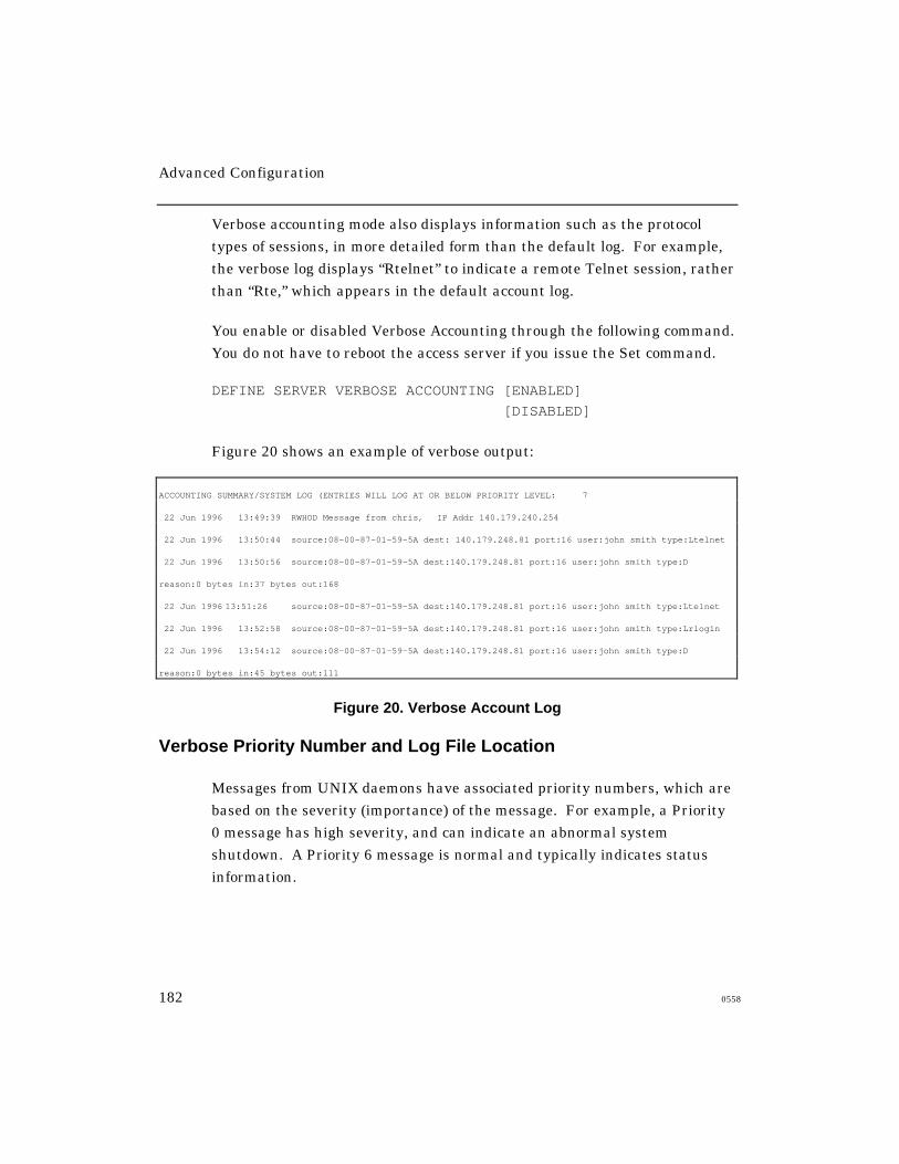
Advanced Configuration
182 0558
Verbose accounting mode also displays information such as the protocol
types of sessions, in more detailed form than the default log. For example,
the verbose log displays “Rtelnet” to indicate a remote Telnet session, rather
than “Rte,” which appears in the default account log.
You enable or disabled Verbose Accounting through the following command.
You do not have to reboot the access server if you issue the Set command.
DEFINE SERVER VERBOSE ACCOUNTING [ENABLED]
[DISABLED]
Figure 20 shows an example of verbose output:
ACCOUNTING SUMMARY/SYSTEM LOG (ENTRIES WILL LOG AT OR BELOW PRIORITY LEVEL: 7
22 Jun 1996 13:49:39 RWHOD Message from chris, IP Addr 140.179.240.254
22 Jun 1996 13:50:44 source:08-00-87-01-59-5A dest: 140.179.248.81 port:16 user:john smith type:Ltelnet
22 Jun 1996 13:50:56 source:08-00-87-01-59-5A dest:140.179.248.81 port:16 user:john smith type:D
reason:0 bytes in:37 bytes out:168
22 Jun 1996 13:51:26 source:08-00-87-01-59-5A dest:140.179.248.81 port:16 user:john smith type:Ltelnet
22 Jun 1996 13:52:58 source:08-00-87-01-59-5A dest:140.179.248.81 port:16 user:john smith type:Lrlogin
22 Jun 1996 13:54:12 source:08-00-87-01-59-5A dest:140.179.248.81 port:16 user:john smith type:D
reason:0 bytes in:45 bytes out:111
Figure 20. Verbose Account Log
Verbose Priority Number and Log File Location
Messages from UNIX daemons have associated priority numbers, which are
based on the severity (importance) of the message. For example, a Priority
0 message has high severity, and can indicate an abnormal system
shutdown. A Priority 6 message is normal and typically indicates status
information.

Advanced Configuration
0558 183
You can specify the message types that the log file accepts based on
severity by assigning a priority number to the account log. The server
then logs only those messages that have a priority number equal to or below
the number you specify. Table 16 lists the message types and their priority
numbers. The default priority number is 5.
You can also specify, through the same command, whether the UNIX host
logs accounting information to a file in the kernel or to a UNIX facility. By
default, the host logs the information to the kernel. If you want the host to
log it to a facility instead, you must set up the facility on the host and
specify it at the access server. Refer to the MAN pages on the UNIX host
for instructions.
Table 16 - Priority Numbers for Messages from UNIX Daemons
Message Type Priority Description
LOG_EMERG 0 A severe condition. The access server usuallybroadcasts a priority 0 message to all users becauseit can affect their ability to work at the host.
LOG_ALERT 1 A condition that the system manager needs tocorrect immediately, such as a corruptedsystem database.
LOG_CRIT 2 A critical condition, such as a hard device error.
LOG_ERR 3 A software error condition.
LOG_WARNING 4 A warning message.
LOG_NOTICE 5 Conditions that are not error, but which mightrequire specific procedures to adjust them.
LOG_INFO 6 Normal, informational messages.
LOG_DEBUG 7 Messages that contain information useful fortesting only.

Advanced Configuration
184 0558
Use this command to specify a priority number:
DEFINE/SET SERVER VERBOSE PRIORITY number LOG FACILITY [USER
number]
[LOCAL number]
To use this command, Verbose Accounting must be enabled. The
following example sets the verbose priority to 7, thereby allowing all
messages to be logged.
Xyplex>> set server verbose priority 7
Clearing the Account LogTo clear information from the account log, you can reboot the access server
or use this command:
Xyplex>> clear server accounting
Associated Displays
The following sections describe the commands that you use to enable,
disable, and view information associated with the accounting feature.
Show/Monitor Server Accounting
These commands display the accounting information that the access server
has logged. Figure 19 shows a sample display. Xyplex recommends that you
set up your terminal to display 132 characters per line.
Show/List/Monitor Server Characteristics
These commands display the maximum number of accounting entries that
the server can store, and indicate whether verbose accounting is enabled.
Advanced Configuration
0558 185
Show/List Unit and Show/List/Monitor Server Alternate Status
These displays indicate:
• Whether SYSLOGD is enabled
• The IP address of the UNIX host where the account log resides
• The location of the account log on the host
Maintaining Boot Records
This section describes commands that change settings in the
Initialization Records (also called “boot records”) of access and printer
servers that have internal, NonVolitile Storage (NVS). These
commands provide an alternative to the Initialization Configuration
menu for changing these settings.
The MAXserver 1608A, 1620, and 1640 Access Servers have
three Initialization Records and support the commands covered
in this section.
NOTE: Network 9000 Access Server 720 modules also have three
Initialization Records. The commands for changing these
records are described in the manual Managing Network 9000
Modules and Power Supplies.
This section describes each setting in an Initialization Record and
explains how to change it. It also includes information about how to
reset all initialization settings to defaults. The section covers the
following topics:
• Viewing initialization parameters
• Status of MAXserver 1608A/1620/1640 Initialization Records
• Enabling and disabling protocols
• Resetting parameters to defaults
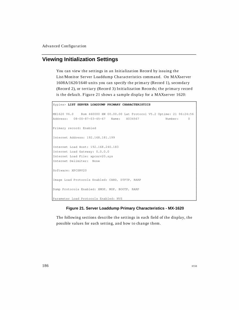
Advanced Configuration
186 0558
Viewing Initialization Settings
You can view the settings in an Initialization Record by issuing the
List/Monitor Server Loaddump Characteristics command. On MAXserver
1608A/1620/1640 units you can specify the primary (Record 1), secondary
(Record 2), or tertiary (Record 3) Initialization Records; the primary record
is the default. Figure 21 shows a sample display for a MAXserver 1620:
Xyplex> LIST SERVER LOADDUMP PRIMARY CHARACTERISTICS
MX1620 V6.0 Rom 460000 HW 00.00.00 Lat Protocol V5.2 Uptime: 21 06:24:56
Address: 08-00-87-03-45-67 Name: X034567 Number: 0
Primary record: Enabled
Internet Address: 192.168.181.199
Internet Load Host: 192.168.240.183
Internet Load Gateway: 0.0.0.0
Internet Load File: xpcsrv20.sys
Internet Delimiter: None
Software: XPCSRV20
Image Load Protocols Enabled: CARD, DTFTP, RARP
Dump Protocols Enabled: XMOP, MOP, BOOTP, RARP
Parameter Load Protocols Enabled: NVS
Figure 21. Server Loaddump Primary Characteristics - MX-1620
The following sections describe the settings in each field of the display, the
possible values for each setting, and how to change them.
Advanced Configuration
0558 187
Status of MX-1608A/1620/1640 Initialization Records
A MAXserver 1608A/1620/1640 maintains three Initialization Records in
NVS. The server first attempts to load its software using the information in
Initialization Record 1, if it is enabled. If it cannot load successfully, it
attempts to load using Record 2, if enabled. If it fails again, it attempts to
use Record 3, if enabled. If all three attempts fail, the server begins the
sequence again with Record 1.
The Primary Record field in Figure 21 shows the status of Initialization
Record 1 either Enabled or Disabled. By default, only Record 1 on a
MAXserver 1608A/1620/1640 is enabled. Initialization records have values
for all settings, whether they are enabled or not. The Primary Record field
does not appear in the Loaddump Characteristics screen for servers with a
single Initialization Record.
This command changes the status of an Initialization Record:
DEFINE SERVER LOADDUMP [record] [ENABLED]
[DISABLED
The record specifies either Primary, Secondary, or Tertiary. The default is
primary. An example follows:
Xyplex>> define server loaddump secondary enabled
Issuing this command enables the access server to attempt to load software
and parameters using Initialization Record 2, if it fails when using Record
1.
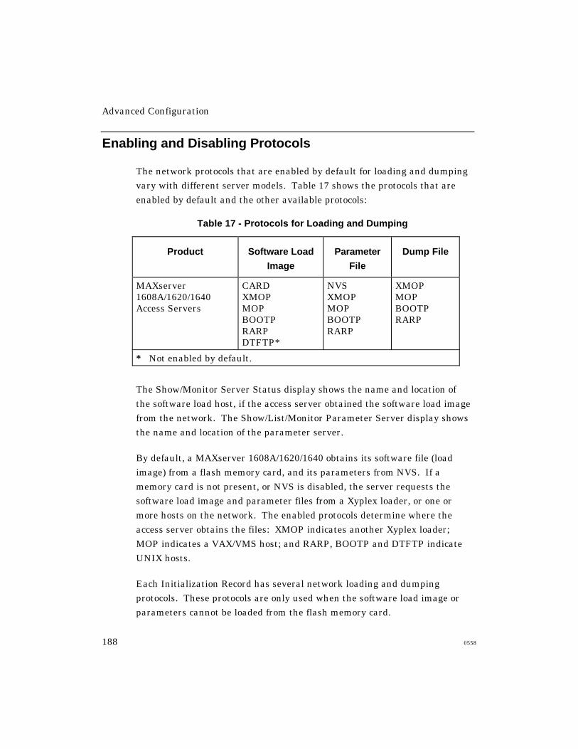
Advanced Configuration
188 0558
Enabling and Disabling Protocols
The network protocols that are enabled by default for loading and dumping
vary with different server models. Table 17 shows the protocols that are
enabled by default and the other available protocols:
Table 17 - Protocols for Loading and Dumping
Product Software Load
Image
Parameter
File
Dump File
MAXserver1608A/1620/1640Access Servers
CARDXMOPMOPBOOTPRARPDTFTP*
NVSXMOPMOPBOOTPRARP
XMOPMOPBOOTPRARP
* Not enabled by default.
The Show/Monitor Server Status display shows the name and location of
the software load host, if the access server obtained the software load image
from the network. The Show/List/Monitor Parameter Server display shows
the name and location of the parameter server.
By default, a MAXserver 1608A/1620/1640 obtains its software file (load
image) from a flash memory card, and its parameters from NVS. If a
memory card is not present, or NVS is disabled, the server requests the
software load image and parameter files from a Xyplex loader, or one or
more hosts on the network. The enabled protocols determine where the
access server obtains the files: XMOP indicates another Xyplex loader;
MOP indicates a VAX/VMS host; and RARP, BOOTP and DTFTP indicate
UNIX hosts.
Each Initialization Record has several network loading and dumping
protocols. These protocols are only used when the software load image or
parameters cannot be loaded from the flash memory card.
Advanced Configuration
0558 189
Changing Protocols through Commands
Use this command to enable or disable software and parameter
loading protocols:
DEFINE SERVER LOAD [record] usage PROTOCOL [protocol] [ENABLED]
[ALL] [ALL] [DISABLED]
The record specifies either Primary, Secondary, or Tertiary. The usage
variable specifies either IMAGE or PARAMETERS. You cannot disable
all protocols in an Initialization Record. An example follows:
Xyplex>> define server load primary image protocol xmop
disabled
Use this command to enable or disable dumping protocols (protocols that the
server uses when dumping its memory contents):
DEFINE SERVER DUMP [record] PROTOCOL [protocol] [ENABLED]
[ALL] [ALL] [DISABLED]
The record variable specifies either Primary, Secondary, or Tertiary. An
example follows:
Xyplex>> define server dump primary protocol rarp disabled
Advanced Configuration
190 0558
CARD, NVS, XMOP, and MOP Protocols
The access server uses the CARD, NVS, XMOP, and MOP protocols to
search for a software load image or parameter file at a particular location,
which is determined by the protocol. You can change the load image
filename by using the command described in “Changing the Software
Filename”. The current load image filename appears in the Software field of
the Loaddump Characteristics display. The XMOP and MOP protocols can
also send a memory dump file to a dump server.
CARD Protocol
The CARD protocol looks for a software load image on a memory card.
This is the default load image protocol for these products. This protocol
does not apply to dump files, since Xyplex memory cards do not function
as dump servers.
NVS Protocol
The NVS protocol looks for a parameter file in NVS. This is the default
protocol for loading parameters on all server models. This protocol does not
apply to the load image or dump files.
XMOP and MOP Protocols
The XMOP and MOP protocols look for a software load image file, a
parameter file, or a dump server. The access server first attempts to use
XMOP, then MOP.
The Xyplex Maintenance Operations Protocol (XMOP) looks for the files on
a Xyplex loader on the network. Refer to the Software Installation Guide
for Xyplex Loader Kits for more information about using XMOP.
Advanced Configuration
0558 191
The DEC Maintenance Operations Protocol (MOP) looks for a software load
image and parameter file on a DEC host that runs the MOP protocol. The
access server can also use MOP to send information to a dump server.
Refer to the Software Installation Guide for VMS Kits for information about
setting up a MOP host.
Changing the Software Filename
The software load image filename appears in the Software field of the
Loaddump Characteristics display. For MAXserver 1608A, 1620, and 1640
units, it is XPCSRV20.sys. Use this command to specify a name for the
software load image file:
DEFINE SERVER LOAD [record] SOFTWARE filename
[ALL]
The record specifies either Primary, Secondary, or Tertiary. The
filename variable specifies the software load image filename. An
example follows:
Xyplex>> define server load primary software XPSPECIAL
BOOTP and RARP Protocols
The Bootstrap Protocol (BOOTP) and the Reverse Address Resolution
Protocol (RARP) look for the software load image and parameter filenames
on a UNIX host. The access server first tries BOOTP, then RARP. You do
not need to supply any additional information in the Initialization Records if
the BOOTP and RARP hosts are configured correctly. The Software
Installation Guide for UNIX Hosts describes BOOTP and RARP setup.
Advanced Configuration
192 0558
DTFTP Protocol
The Directed Trivial File Transfer Protocol (DTFTP) searches for a
specific software load image file on a UNIX host. You supply the name of
the software load image file, the IP address of the load host, and the IP
address of the access server. If the load host exists on a remote branch of
the network, you must also provide the IP address of a gateway. Default
values do not exist for this information. The access server does not use
DTFTP to obtain a parameter file or to send information to a dump
server. Unless you use DTFTP, you do not have to specify IP settings in
the Initialization Record.
The following commands provide information for loading through DTFTP.
Each setting is covered in a subsequent section.
Internet Load Address:
DEFINE SERVER LOAD [record] IP ADDRESS ip-address
[ALL]
Internet Load Host:
DEFINE SERVER LOAD [record] IP HOST ip-address
[ALL]
Internet Load Gateway:
DEFINE SERVER LOAD [record] IP GATEWAY ip-address
[ALL]
Internet Load File:
DEFINE SERVER LOAD [record] IP FILE "/path/filename"
Advanced Configuration
0558 193
IP Address
The IP address specifies the IP address of the access server, which the
load server host uses for DTFTP loading. (This is the address assigned
through the Define Server IP Address command.)
MAXserver 1608A/1620/1640 Access Servers allow you to change the IP Load
Address in the three Initialization Records. Figure 21 shows 0.0.0.0 in this
field; this is the default address on these units. An example follows:
Xyplex>> define server load primary IP address
192.168.118.2
IP File
The IP File field specifies the pathname and filename of the software load
image on the IP Load Host. The access server searches for this filename
when it uses the DTFTP protocol to obtain the software load image during
initialization. An example follows:
Xyplex>> define server load IP file "/usr/xyplex/images/xpcsrv20.sys"
IP Host
The IP Host specifies the IP address of the host on the network where the
software load image file resides. Figure 21 shows 0.0.0.0 in this field; this is
the default. An example follows:
Xyplex>> define server load primary IP host
192.168.119.3

Advanced Configuration
194 0558
IP Gateway
The IP Gateway specifies the IP address of a gateway on the network,
which the access server uses to gain access to the IP load host. Not all
network configurations require a gateway. Figure 21 shows 0.0.0.0 in this
field; this is the default. An example follows:
Xyplex>> define server load primary IP gateway
192.168.111.5
Resetting Parameters to DefaultsThe following command resets all initialization settings to defaults. Note
that the command is not supported by all server models.
DEFINE SERVER LOADDUMP [record] DEFAULT
[ALL]
The record specifies either Primary, Secondary, or Tertiary.
If you specify Secondary or Tertiary, this command also disables the
Initialization Record. (This is because these records are disabled by
default.)
Using Security Features
Xyplex Access Servers offer security features that control access to server
ports and devices on the network. You can use these features individually,
or combine them to achieve different levels of network security. This
section describes how these following features affect your networking
environment and discusses considerations that you should be aware of
before using them at your site.
This section describes how the following features affect your
networking environment, and describe the commands that you use to
enable each feature.
Advanced Configuration
0558 195
• Controlling Access to the Server
PasswordsPrivilege levelsThe Kerberos Security SystemSecurID AuthenticationRADIUS AuthenticationRADIUS Callback (Dialback)
RADIUS Accounting
• Controlling Access to Network Resources
The Port Access Characteristic
Limited View
Authorized Groups
Service Passwords
Internet Security
• Using Access Server Scripts to Enhance Security
Login Scripts
Dialback Modem Control Scripts
Passwords
You can activate or change these server passwords:
• Login password (default: ACCESS)
• Privilege password (default: SYSTEM)
• Maintenance password (default: None)
These passwords prevent persons who do not know them from accessing the
server. The privileged and maintenance passwords have default values,
which you should change to other values as part of your basic server setup.

Advanced Configuration
196 0558
Login Password
When you enable the Login Password feature on a server port, a person
attempting to log on to that port must enter a password in order to gain
access. A single password is used at all ports where the feature is enabled.
The login password feature is optional; the server does not prompt for it
unless you enable it on a port.
The default login password is ACCESS.
Use the following commands to enable the Login Password feature and
define a password. The feature is disabled by default.
DEFINE PORT [port-list] PASSWORD [ENABLED | ALL | DISABLED]
DEFINE/SET SERVER LOGIN PASSWORD "password"
Examples
Xyplex>> define port 1-8 password enabled
Xyplex>> define server login password "login123"
Login Password Prompt
The Login Password prompt appears when a user attempts to log on to a
port where the Login Password feature is enabled. The default prompt is:
#
Use the following command to change the password:
DEFINE/SET SERVER LOGIN PROMPT “prompt-string”
Privilege Password
You must enter the privilege password to set a port to privileged mode.
The default password is SYSTEM. Xyplex recommends that you change
it, to restrict access to the commands that:

Advanced Configuration
0558 197
• Change the server’s settings
• Affect other users’ ports
• Affect access to destinations on the network
You might want to change the privilege password periodically, to limit the
number of users who can set privileged mode.
Refer to “Privilege Levels” for more information.
Use this command to define the privilege password:
DEFINE/SET SERVER PRIVILEGE PASSWORD "password"
Example
Xyplex>> define server privilege password "xyplex9"
Maintenance Password
When you enable the Maintenance Password feature, you must enter a
hexadecimal password when attempting to enter the following commands:
• Remote Console
• DECnet NCP Trigger command
• NCP Load commands
These commands are only useful to users who manage or maintain the
server network. The default Maintenance Password is None. Use the
following command to change the maintenance password:
DEFINE/SET SERVER MAINTENANCE PASSWORD "password"
Example
Xyplex>> define server maintenance password "654321"
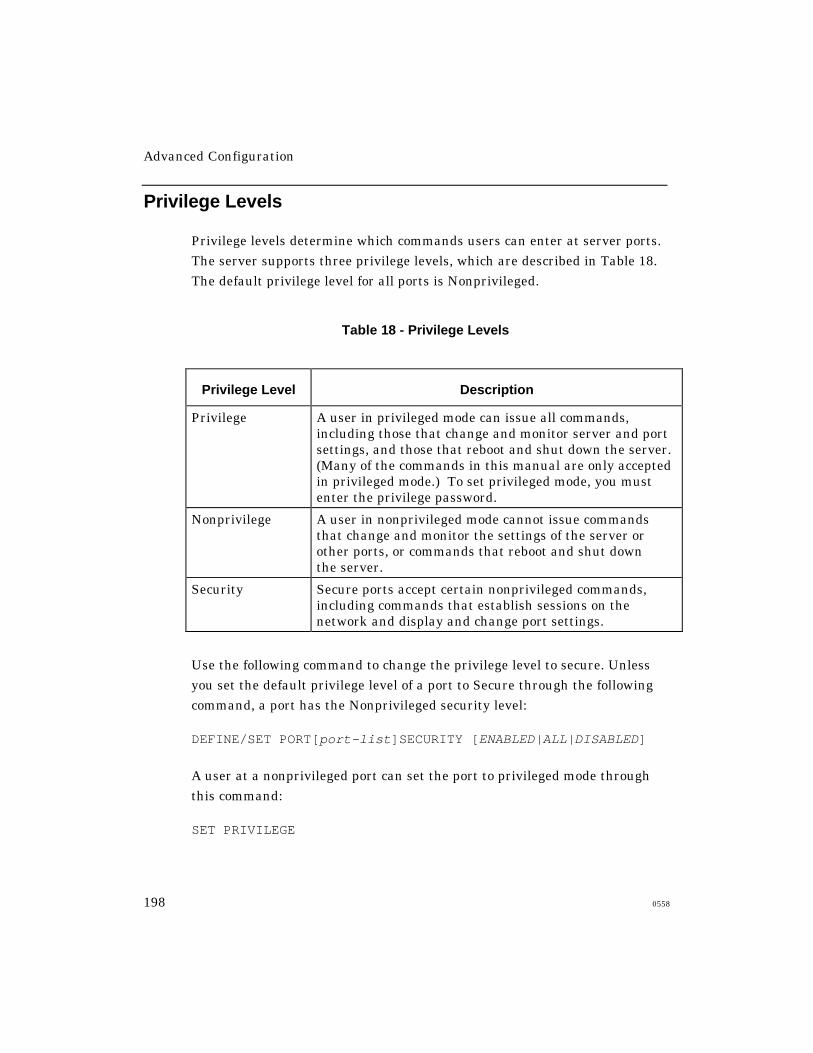
Advanced Configuration
198 0558
Privilege Levels
Privilege levels determine which commands users can enter at server ports.
The server supports three privilege levels, which are described in Table 18.
The default privilege level for all ports is Nonprivileged.
Table 18 - Privilege Levels
Privilege Level Description
Privilege A user in privileged mode can issue all commands,including those that change and monitor server and portsettings, and those that reboot and shut down the server.(Many of the commands in this manual are only acceptedin privileged mode.) To set privileged mode, you mustenter the privilege password.
Nonprivilege A user in nonprivileged mode cannot issue commandsthat change and monitor the settings of the server orother ports, or commands that reboot and shut downthe server.
Security Secure ports accept certain nonprivileged commands,including commands that establish sessions on thenetwork and display and change port settings.
Use the following command to change the privilege level to secure. Unless
you set the default privilege level of a port to Secure through the following
command, a port has the Nonprivileged security level:
DEFINE/SET PORT[port-list]SECURITY [ENABLED|ALL|DISABLED]
A user at a nonprivileged port can set the port to privileged mode through
this command:
SET PRIVILEGE
Advanced Configuration
0558 199
To restore nonprivileged mode, issue this command:
SET NOPRIVILGE
The Secure level might be appropriate for many ports. Secure ports accept
commands that:
• Establish sessions
• Display information about the port and network destinations
• Change some port settings
You can change the following port settings while in secure mode:
• Session switching characters
• Multisessions feature
• TN3270 feature
Secure ports do not accept commands that affect:
• Server settings
• Other user's ports
• The accessibility of network destinations
If you want to limit the use of a port to commands that users need for
normal daily work, consider making the port secure by default. The
Commands Reference Guide describes commands that are available at
secure ports only.
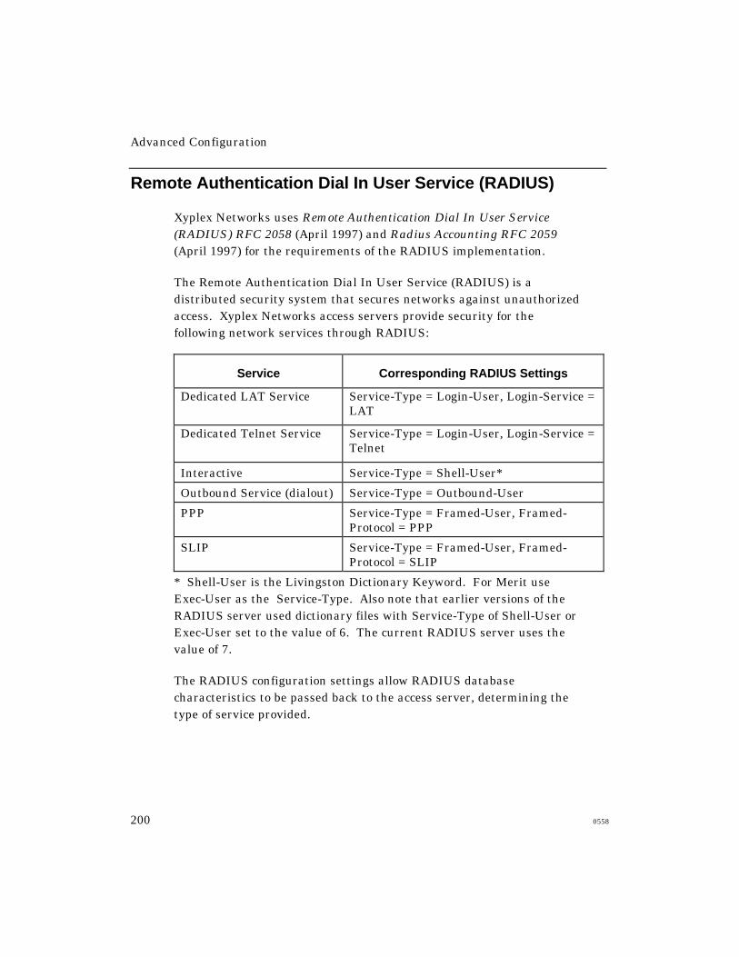
Advanced Configuration
200 0558
Remote Authentication Dial In User Service (RADIUS)
Xyplex Networks uses Remote Authentication Dial In User Service(RADIUS) RFC 2058 (April 1997) and Radius Accounting RFC 2059(April 1997) for the requirements of the RADIUS implementation.
The Remote Authentication Dial In User Service (RADIUS) is adistributed security system that secures networks against unauthorizedaccess. Xyplex Networks access servers provide security for thefollowing network services through RADIUS:
Service Corresponding RADIUS Settings
Dedicated LAT Service Service-Type = Login-User, Login-Service =LAT
Dedicated Telnet Service Service-Type = Login-User, Login-Service =Telnet
Interactive Service-Type = Shell-User*
Outbound Service (dialout) Service-Type = Outbound-User
PPP Service-Type = Framed-User, Framed-Protocol = PPP
SLIP Service-Type = Framed-User, Framed-Protocol = SLIP
* Shell-User is the Livingston Dictionary Keyword. For Merit useExec-User as the Service-Type. Also note that earlier versions of theRADIUS server used dictionary files with Service-Type of Shell-User orExec-User set to the value of 6. The current RADIUS server uses thevalue of 7.
The RADIUS configuration settings allow RADIUS databasecharacteristics to be passed back to the access server, determining thetype of service provided.
Advanced Configuration
0558 201
NOTE: You can only configure one authentication method on any singleport. If you try to enable RADIUS after another authenticationmethod is defined (for example, Kerberos or SecurID), theattempt fails and produces an error message.
Understanding the RADIUS Authentication Process
The access server combined with the RADIUS server secures networksagainst unauthorized access. RADIUS authentication occurs through aseries of communications between the access server and the RADIUSserver. Once RADIUS has authenticated a user, the access serverprovides that user with access to the appropriate network services. TheRADIUS server maintains a database that contains user authenticationand network service access information.
The following example describes the steps in the RADIUSauthentication process. In this example, the user attempts to gainaccess to an access server port.
1. The access server prompts the user for a username and password. The
username can be up to 121 characters. All displays which show the
username continue to print only the first 16 characters.
2. The access server takes the username and password, creates an access-
request packet identifying the access server making the request, the
username and password, and the port being used. The access server also
suggests the Service-Type for the connection based on the configuration
of the port. The default Service-Type is Shell-User. The access server
then sends the packet to the designated RADIUS server for
authentication.
NOTE: The user password is encrypted to prevent it from being
intercepted and reused by an unwanted user. Do this by
generating a random vector and placing it in the request
header. A copy of the random vector is MD5 encoded using
the configured secret. The user’s password is then encrypted
by xoring it with the encoded copy of the random vector.
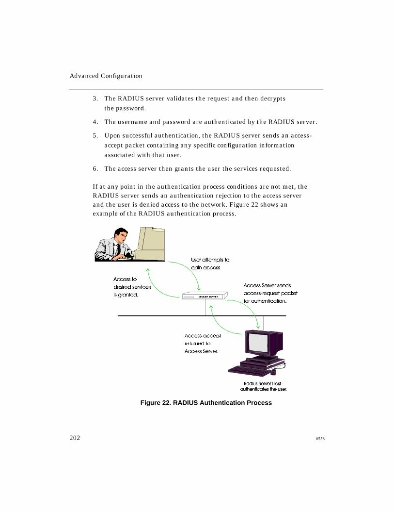
Advanced Configuration
202 0558
3. The RADIUS server validates the request and then decrypts
the password.
4. The username and password are authenticated by the RADIUS server.
5. Upon successful authentication, the RADIUS server sends an access-
accept packet containing any specific configuration information
associated with that user.
6. The access server then grants the user the services requested.
If at any point in the authentication process conditions are not met, theRADIUS server sends an authentication rejection to the access serverand the user is denied access to the network. Figure 22 shows anexample of the RADIUS authentication process.
Figure 22. RADIUS Authentication Process

Advanced Configuration
0558 203
Using Kerberos Authentication
Kerberos is a network authentication service developed by the
Massachusetts Institute of Technology. It provides a central database of
encrypted (coded) data, such as user passwords. Clients such as access
servers use the information in the database to verify login requests.
Kerberos encrypts data using the Department of Defense Data Encryption
Standard (DES). Xyplex Access Servers with at least 1 MB of memory
support Kerberos.
You can set up access servers running V5.3.1 or later software to verify
login requests through Kerberos Version 4 or 5. SNMP must be also
enabled on the server to use Version 5.
A Kerberos system includes a Kerberos Master host and one or more
Kerberos Server hosts. The Master host maintains the database of
encrypted information for a network organization called a realm. The
Master host provides data for the Server hosts when clients contact the
Server hosts to verify login requests. You define Kerberos passwords for
access server users on the Kerberos Master host.
NOTE: Kerberos requires software that runs on the TCP/IP host that
serves as a Kerberos Master. Contact Xyplex Customer Support if
you need this software.
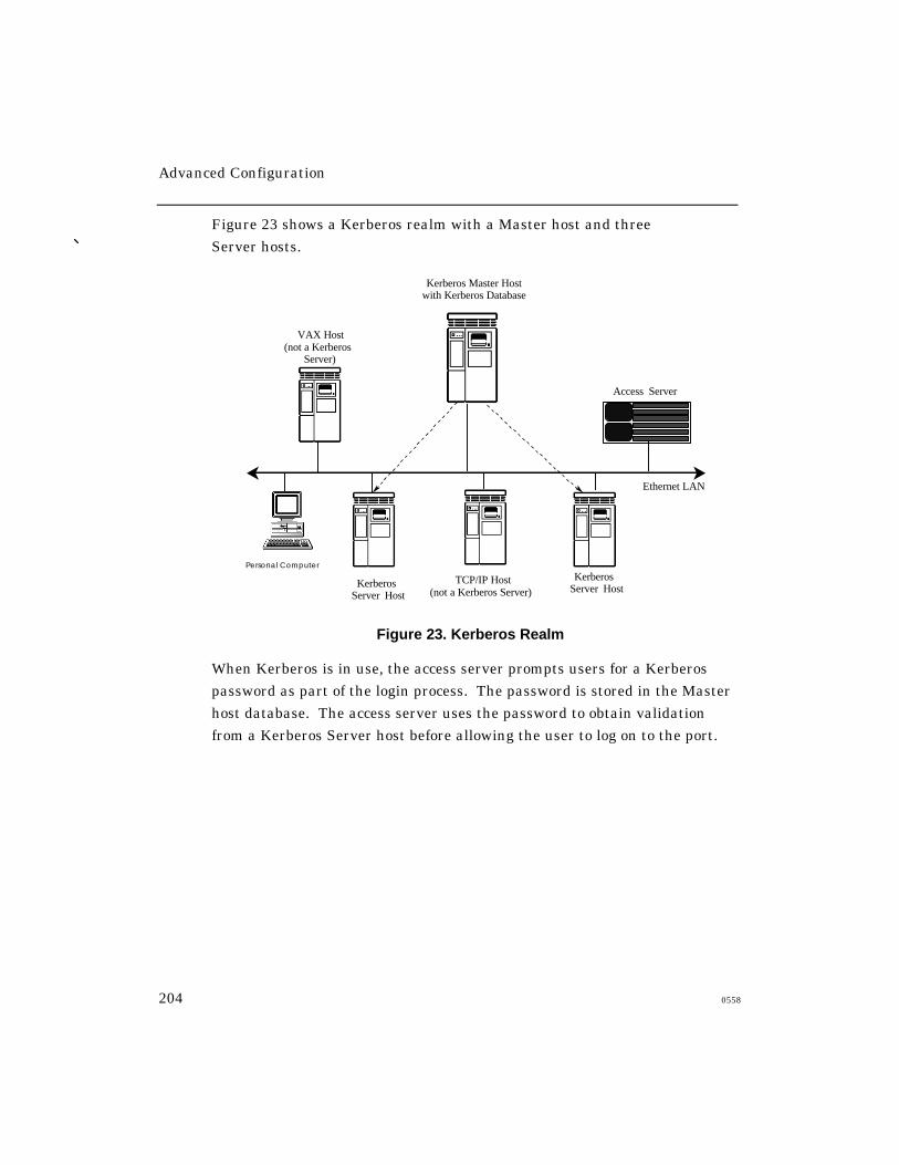
Advanced Configuration
204 0558
Figure 23 shows a Kerberos realm with a Master host and three
Server hosts.
Kerberos Master Host with Kerberos Database
Kerberos Server Host
Kerberos Server Host
Ethernet LAN
VAX Host (not a Kerberos
Server)
Access Server
Personal Computer
TCP/IP Host (not a Kerberos Server)
Figure 23. Kerberos Realm
When Kerberos is in use, the access server prompts users for a Kerberos
password as part of the login process. The password is stored in the Master
host database. The access server uses the password to obtain validation
from a Kerberos Server host before allowing the user to log on to the port.
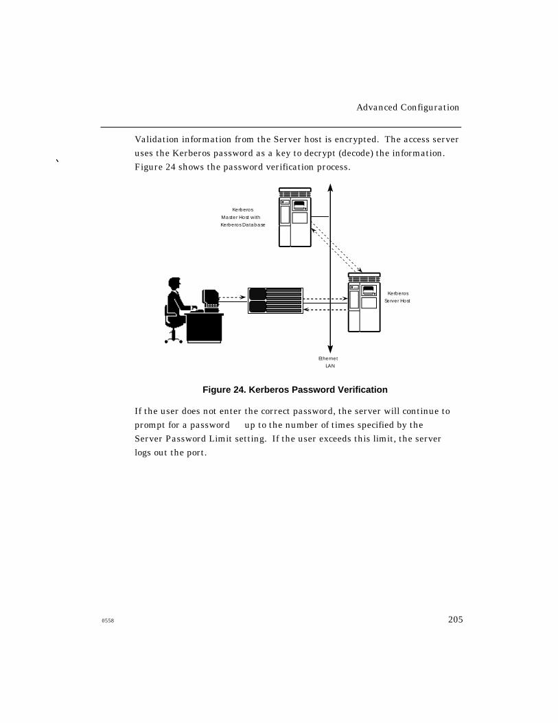
Advanced Configuration
0558 205
Validation information from the Server host is encrypted. The access server
uses the Kerberos password as a key to decrypt (decode) the information.
Figure 24 shows the password verification process.
Kerberos
Server Host
Kerberos
Master Host with
Kerberos Database
Ethernet
LAN
Figure 24. Kerberos Password Verification
If the user does not enter the correct password, the server will continue to
prompt for a password up to the number of times specified by the
Server Password Limit setting. If the user exceeds this limit, the server
logs out the port.

Advanced Configuration
206 0558
Using SecurID Authentication
SecurID is a system of server software, client software, and SecurID
cards. The system is designed to secure a TCP/IP network, preventing
unauthorized users from gaining access to resources on the network, but
allowing authorized users to access the resources easily.
When SecurID is in use, a user must specify a SecurID Personal
Identification Number (PIN) and the password (PASSCODE) shown
on a SecurID card to log on to the server. Once the user has logged
on to the server, he can connect to resources on the network. These
resources can also be protected through Kerberos authentication or
other security features.
The following sections cover:
• SecurID Client Features
• SecurID Client Setup
SecurID Client Features
The following sections describe the key features of the Xyplex
SecurID client implementation.
Certification and Interoperability Status
Xyplex products are certified by Security Dynamics Technologies, Inc.
Xyplex products that support the SecurID client implementation
support both the DES and SDI encryption mechanisms. The SecurID
client implementation operates with Security Dynamics ACE/Server.
Advanced Configuration
0558 207
NOTE: Compatibility with ACE/Server Software. The SecurID client
software that runs on the access server is based on V1.1 of the
ACE/Server software supplied by Security Dynamics
Technologies, Inc. The software operates with ACE/Server hosts
running ACE/Server software V1.1, or later.
Compatibility with Other Xyplex Security Mechanisms
SecurID authentication can be used in conjunction with other Xyplex access
security methods. Port password access occurs before Kerberos
authentication. Authentication via SecurID occurs after Kerberos
authentication occurs, but before the server runs a dialback script and/or
login script. After the user has been authenticated and has logged on to the
server port, other security mechanisms (such as Internet Security, LAT
groups, dedicated services, additional SecurID authentication on network
hosts, etc.) allow or prevent access to network resources.
Standard Setup and Administration Procedures
You use standard setup and administration procedures to configure the
access server as a SecurID client on the ACE/Server host, and to administer
the system (e.g., adding users, etc.). These procedures are described in the
ACE/Server Manual from Security Dynamics Technologies, Inc.
Time Synchronization
Xyplex Access Servers use the time specified by the ACE/Server as its
system clock time. The access server updates this time from the
ACE/Server every 24 hours.
Advanced Configuration
208 0558
Xyplex Product Support
The SecurID feature is only supported on units that use enhanced or Multi-
Megabyte load images (XPCSRV20.SYS and XPCS00C.SYS). These load
images run on the following units:
• Network 9000 Model 720
• MAXserver 1604, 1608B, 1620, 1640 units with at least 2
MB of memory
• MAXserver 1820
Using Internet Security
The Internet security feature enables you to restrict inbound and outbound
connection requests on an IP-based network. You can restrict outbound
connections from specific ports to specific IP addresses, and to specific nodes
at an IP address. Similarly, you can restrict inbound connections to server
ports from specific IP addresses, and from specific nodes at an IP address.
To use this feature, you create entries in an Internet Security table for each
port. The entries provide information about where you allow connection
requests on the network. The security tables allow all connections by
default.
Use the Define/Set Port IP Security commands to set the security for
each port.

Advanced Configuration
0558 209
Controlling Access to Network Resources
The access server offers several ways to prevent or restrict access to
resources on the network. These include:
• Setting Port Access
• Setting Limited View
• Authorized Groups
• Service Passwords
• Internet Security Table
These features are described in the following sections.
Make sure that security is set up at the hosts and other devices on your
network, as well as on the access server. The security features you can use
include usernames, passwords, and host-specific security settings.
Port Access Setting
The Port Access setting specifies the type of connections that the server
allows to and from a port:
• Local
• Remote
• Dynamic
• None
Local is the default. The local default setting allows the device to
make to the LAN to the network. The Remote setting allows only
from the LAN to the port. This setting is appropriate if the device
connected to the port is a line printer. Dynamic allows either
incoming or outgoing calls. None allows no calls from either
direction. This setting might be appropriate on a printer server that
has only one parallel printer connected to it. In this case, you might
improve printing speed if you connect the printer to Port 3 and
define the access setting for Port 4 to None.

Advanced Configuration
210 0558
Use these commands to define the Port Access type. The default setting
is Local.
DEFINE/SET PORT [port-list] ACCESS [LOCAL]
[ALL]
[REMOTE]
[DYNAMIC]
[NONE]
Example
Xyplex>> define port 10 access dynamic
Limited View Protection for Network Resources
The Limited View setting prevents users at nonprivileged and secure
ports from using commands that display the names and addresses of
nodes, IP domains, and services on the network. These commands
include Show/List Destinations, Show/List Domains, Show/List Nodes,
and Show/List Services.
This setting enhances network security because it limits the view of the
network to users at ports where the setting is enabled. It does not directly
prevent a user from gaining access to a resource, however, if the user learns
the name or address of the resource from another source.
This command enables or disables the Limited View setting:
DEFINE/SET PORT [port-list] LIMITED VIEW [ENABLED]
[ALL]
[DISABLED]
Example
Xyplex>> define port 3-7 limited view enabled

Advanced Configuration
0558 211
Authorized LAT Service Groups
The authorized groups setting restricts access from specified ports to groups
of LAT services that you specify with group codes. When a network user
attempts to connect to a service, the access server matches the group code of
the port to the group code of the service node. The server allows a
connection if the codes match, but denies the connection if the codes do not
match. Use the following command to define authorized groups for ports.
Default: Group 0 Enabled; Groups 1-255 Disabled.
DEFINE/SET PORT [port-list] AUTHORIZED GROUPS [group-list]
[ENABLED]
[ALL] [ALL] [DISABLED]
Example
Xyplex>> define port 3-5 authorized groups 48-60 enabled
Password Protection for LAT Services
When you define a LAT service, you can require that users enter a
password to access that service. The server prompts for the password after
the user enters a Connect command to start a session with the service, and
before the logon banner for the service node appears. There is no default
LAT service password.
DEFINE/SET SERVICE PASSWORD password
ExampleXyplex>> define service password chris

Advanced Configuration
212 0558
Time Server Enhancement
When an access server has a configured time server, the access servershortly after it boots does a directed UDP query for TIME service to theTime server. If there is no response, and the time server is ENABLED(Not Required), there is an attempt to get the time from other serversaccording to the following priority:
Time Server (via UDP port 37)
Kerberos Server(s)(via UDP port 37)
SecurID Server(s)(via UDP port 37)
XMOP/MOP load server
UDP Broadcast (via UDP port 37)
Clock starts at zero (and can then be manually configured)
Time, Kerberos, or SecurID servers are configurable together butimplemented as mutually exclusive with regard to querying for thetime. If both the Time and Kerberos Servers are defined, then onlythe Time Server is used. If both the Time and SecurID servers aredefined, then only the Time Server is used. If no Time server isdefined but a Kerberos and SecurID servers are defined, then theKerberos servers are used. If no Time and no Kerberos server aredefined but a SecurID server is defined, then the SecurID server isused. There is a daily attempt to resynchronize with the TIMESERVER at 2:00 a.m, just as there is an attempt to resynchronizewith Kerberos or SecurID Time Servers.
Servers which run Kerberos or SecurID should have the Time Serveraddress set to 0. Kerberos works with a configured Time Servermatching the Primary Kerberos Server. However, if you have asecondary Kerberos Server, the secondary Kerberos server is neverqueried for the time if the Time Server is non-zero.
Once the time is obtained by one of these methods, the time serverinformation is saved and displayed in the field labeled “Time ReceivedFrom:” on the SERVER ALTERNATE STATUS display.
Advanced Configuration
0558 213
The command syntax is as follows:
SET/DEFINE SERVER TIME SERVER ENABLED | REQUIRED n.n.n.nSET/DEFINE SERVER TIME SERVER DISABLED
If the timer server is required, only this time server is used to obtainthe time. On failure, a repeat every minute to request the time fromthe required server occurs. If the time server is ENABLED, then thisserver is tried first before the other servers. Repeated attempts aremade to query that server for one minute before checking time byother methods. A time server of zero and/or DISABLED means thetime server is not used.
When the command is SET and the Time Server is ENABLED orREQUIRED, an immediate query time call to that time server occurs.Repeated attempts are made to query that server for one minute oruntil a response is received.
NOTE: The SET SERVER TIME SERVER DISABLED command doesnot disable the time server until the next resynchronizationtime, or 2:00 a.m. This may result in an extra broadcast goingout at resynchronization time, or 2:00 a.m.
Only the DEFINE SERVER TIME ZONE command is implemented. The
SET SERVER TIME ZONE command is ignored.
If the Time server is defined, it shows in the Show Server window.
Advanced Configuration
214 0558
RADIUS Security
The right amount of security varies from network to network, depending on
what data resides on the network and on who should -- and should not --
have access to it. A good security strategy usually involves several layers of
protection, such as passwords, dial-back security, and detection of illegal
attempts to gain access to the network.
These traditional methods are rarely enough today, however. As remote
access becomes more popular and more business data is transmitted over
networks, it becomes more important -- and more difficult -- to provide the
right balance of access and security for a company's network. Simple
password systems are vulnerable to attack, and mobile users need a more
flexible system than dial-back.
While some of today's security systems address one or another aspect of
security, the most comprehensive and sophisticated approach is provided by
the Remote Authentication Dial In User Service (RADIUS). RADIUS is a
standard defined by the Internet Engineering Task Force (IETF) that is
quickly being adopted in the networking industry. It is a distributed
security system that provides multiple levels of security options to create a
very secure dial-in access authentication system.
Multiple Levels of Security
RADIUS combines several approaches. The first layer is a standard
password protection system with a user ID and password. This system,
called a multiple-use password system since the user enters the same
password each time they log in, is vulnerable to attack. Multiple-use
passwords can be stolen, or even guessed by a computer program using a
dictionary, and then used to break into a network. The solution is single-
use, or time-sensitive, passwords.
Advanced Configuration
0558 215
Challenge/Response Process
Therefore, RADIUS includes a second level of protection, an optional
challenge/response process based on single-use passwords. This is usually
accomplished with a special hand-held device that accepts the challenge and
computes the correct response. This authentication capability can be
distributed among multiple authentication servers for greater security.
The third level of security is an optional configuration script that
dynamically configures the port with optional source destination filters.
Each user's network access can be controlled by a set of rules tailored to the
individual user, restricting the user to specific areas of the network.
Easy Installation and Integration
There are additional advantages to using RADIUS. It is very easy to install
and it integrates easily with other existing security systems. For example, a
RADIUS authentication server can be configured to connect to an existing
Kerberos server for user ID and password support, saving the time and
effort of setting up a new authentication server from scratch.
Getting Started - RADIUS
The basic steps for configuring RADIUS authentication are:
1. Configuring the RADIUS server on the Host.
2. Configuring RADIUS on the Access Server.
3. Defining RADIUS Authentication.
4. Selecting Access Server Service.

Advanced Configuration
216 0558
Configuring the RADIUS Server on the Host
Before you can configure RADIUS on your access server you mustconfigure a RADIUS server on your RADIUS server host.
In general, RADIUS server implementations are available on theInternet. These implementations generally use a daemon process thatinteracts with RADIUS clients (located on access servers and otherremote access devices).
The daemon uses a list of clients and associated secrets that it shareswith these clients. The per-client secret is used to encrypt and validatecommunications between the RADIUS server and the client. The fileused to keep the client list and secrets is the “clients” file.
Another file used by the daemon to store the users that areauthenticated is the “users” file. The “user” file contains the RADIUSattributes associated with a particular user. As a minimum, this filemust contain the user’s username and password (depending on theRADIUS server used).
To configure the RADIUS server, refer to your RADIUS hostdocumentation. Xyplex Networks recommends that you use the MeritRADIUS server implementation. Information for the Merit RADIUSserver can be found at http://www.merit.edu. Refer to the GOPHERSERVER and the MERIT Network Information Center for new releases.
Configuring RADIUS on the Access Server
In order to configure RADIUS, ensure that the access server has aminimum of 3–MB of memory installed.
To configure RADIUS authentication on your access server, completethese steps:
1. Create a copy of your present parameter file.

Advanced Configuration
0558 217
For example, copy the present x123456.sys file to a file called
x123456.old. This copy can be used if you need to restore your
old parameters.
2. Insert the flash card supplied with your access server software kit or
software update into the memory card slot.
3. Boot up the new image.
4. Enable RADIUS on the access server using the following command:
Xyplex>> DEFINE SERVER RADIUS ENABLED
5. Reboot the access server.
6. Confirm that RADIUS is enabled using the following command:
Xyplex> SHOW SERVER RADIUS
The system displays a screen similar to the following:
Xyplex> SHOW SERVER RADIUS
AS/720 V6.0.1 Rom 4A0000 HW 00.02.00 Lat Protocol V5.2 Uptime: 0 04:31:26xx Mar 199x 20:28:29
RADIUS Primary Server: 140.179.248.145Resolved Address: 140.179.248.145 Secret: Configured
RADIUS Secondary Server:Resolved Address: 0.0.0.0 Secret: Default
RADIUS Port Number: 1645 Request Timeout (sec): 5RADIUS Logging: ENABLED Chap Challenge Size: 16RADIUS Server Retries: 3RADIUS Ports Enabled: 2
Successful Logins: 4 Configuration Failures: 0Authentication Failures: 0 Policy Failures:
0
Server access attempts Primary Secondary Successful: 4 0 Failed: 0 0

Advanced Configuration
218 0558
The Chap Challenge Size is the size of the challenge sent to the peer forChap and to the RADIUS server for verification. Note, the peer shouldwork with any size challenge. However, the current RADIUS serversonly support challenge sizes of 16.
The following table describes the various RADIUS counters:
Field Description
Successful Logins Number of successful logins.
AuthenticationFailures
Number of rejections returned by theRADIUS Server.
ConfigurationFailures*
Number of failures returned by theRADIUS server due to incorrect valuesbeing entered for supported attributes.
Policy Failures* Number of failures returned by theRADIUS server due to a port beinghard-configured for one type ofRADIUS service-type, but the RADIUSserver returned a different service-type.
Policy failures also occur when theservice-type selected by APD orSolicitation does not match the service-type returned by the RADIUS server.
* These failures are local failures only and are not attributed to theRADIUS server. However, they may be a result of bad values from theRADIUS server that cannot be handled.
7. Check the primary/secondary RADIUS server host to ensure that the
RADIUS server client database has been configured.
Advanced Configuration
0558 219
8. Specify the secret shared between the RADIUS client and the primary
RADIUS Server. Define the client secret on the access server using the
following command:
Xyplex>> DEFINE/SET SERVER RADIUS PRIMARY SECRET secret
NOTE: This secret must match the secret defined in the client file
located on the RADIUS host.
9. Define the RADIUS primary server using the following command:
Xyplex>>DEFINE/SET SERVER RADIUS PRIMARY SERVER<ip-address> <domain name>
<none>
Specify either the IP address or the domain name of the RADIUSserver. When "none" is specified, the secret is reset to the default value(secret).
NOTE: If you plan to use a secondary server, complete steps 8 and 9again replacing “Primary” with “Secondary” in the command.
The secondary server is used when:
• The primary server cannot be accessed.
• The primary server rejects the authentication request (wrongpassword, no user record).
You can now enable RADIUS on the individual access server ports.
Configuring RADIUS Authentication on a Per-Port Basis
RADIUS allows you to enable authentication on a per-port basis. TheService-Type used by a port can be one of the following types:
• Selected by the user
• Selected by the Access Server
• Selected by RADIUS

Advanced Configuration
220 0558
User Service-Selection
The User Service-Selection uses either AutoProtocol Detect (APD) orRADIUS Solicitation modes to provide the Service-Type selection.
User Service-Selection — Uses either AutoProtocol Detect (APD) orRADIUS Solicitation modes to provide the Service-Type selection.These modes allow users to select a service explicitly by entering achoice at the solicitation prompt or implicitly by starting a protocolallowing APD to determine the protocol.
Access Server Service-Selection — Statically configure the port for adesired Service-Type (PPP, SLIP, Telnet, etc.). Once configured, this isthe only service you can access.
RADIUS Service-Selection — Used when no service-type is configuredusing Access Service-Selection or User Service-Selection. The accessserver defaults to “Shell-User” but accepts whatever Service-Type isreturned by the RADIUS server.
Using AutoProtocol Detect (APD)
For APD remote access login, the actual communication with theRADIUS server is held off until APD determines the protocol type beingused. After the protocol is determined, the authentication is made withthat protocol as the Service-Type. If a Service-Type other than therequested Service-Type is returned, the port is logged off (this isconsidered a policy failure). If other attributes, such as Framed-Addressare returned from a configuration record, they are applied to the currentsession only. Once the session is terminated, any parameters configuredthrough RADIUS return to their original values.
Advanced Configuration
0558 221
Defining the RADIUS Solicitation Mode
The RADIUS Solicitation Mode allows you to configure individual portsto display a prompt before the username and password sequence. Thisprompt describes the Service-Type option and is used to determine whatto send as the desired Service-Type to the RADIUS server. The accessserver sends the Service-Type to the RADIUS server. If the RADIUSserver returns a Service-Type other than the Service-Type requested,the port is logged off.
To enable the RADIUS Solicitation Mode, enter the following command:
Xyplex>> DEFINE/SET PORT n RADIUS SOLICITS ENABLED
The port login sequence appears as follows:
Service-Type:PPP=1, SLIP=2, Shell-User=3, Telnet=4, LAT=5login (1-5):Username>Password>
To select a Service-Type, enter the corresponding number at thelogin: prompt. For example, to select the Service-Type Shell-User,enter the number 3 at the login: prompt.
Access Server Service-Selection
The Access Server Service-Selection mode operates when a Service-Type isdefined on a port and no APD or RADIUS Solicitation is configured. Oncedefined, this Service-Type is the only service accessible.
Defining PPP and SLIP Authentication
To define PPP or SLIP on an access server port, use one of thefollowing commands:
Xyplex> DEFINE PORT n PPP ENABLEDXyplex> DEFINE PORT n SLIP ENABLED
Advanced Configuration
222 0558
When an access server port has PPP or SLIP configured and RADIUSenabled, the access server sends the service type and frame protocol tothe RADIUS server. The RADIUS server authenticates the informationand returns the configuration information for the PPP or SLIP remoteaccess login.
Your RADIUS authentication record must contain a service type ofFramed-User and you must have Frame-Protocol PPP (or SLIP), or youare logged off the port. The following example shows an authenticatedrecord returned from the RADIUS server.
Password = “password”User-Service-Type = Framed-UserFramed-Protocol = PPPFramed-Address = 172.19.250.85
In this example, the Framed-Address returned by the RADIUS server isapplied to the PPP link and is used as the remote IP address duringPPP negotiations. No other address may be used by this PPP peer.
NOTE: If RADIUS is enabled on a port (not by PAP/CHAP),the port expects the username and password to beentered interactively.
Advanced Configuration
0558 223
Defining PPP PAP Authentication
This is a privileged command. To define PPP PAP authentication to anaccess server port, enter the following command:
Xyplex>> DEFINE/SET PORT n PPP PAPRADIUS|KERBEROS|ENABLED|DISABLED
The access server uses the RADIUS database to authenticate theusername and password in a PPP PAP authentication request. TheRADIUS server authenticates the user and returns the IP and/or IPXconfiguration information if it is contained in the user record.
NOTE: When using PPP PAP authentication, you may also have normalRADIUS authentication enabled. The result of this is thatauthentication occurs twice. Once for normal RADIUS and againfor PPP PAP. When this occurs, the username and password maybe the same or different but in either case, the Service-Type andprotocol must be appropriate.
You have up to three tries to enter your correct username and password
before RADIUS logs the port out.
NOTES: This command works with Windows 95 Dialup Networking and
MacTCP. Other systems may have stacks that will, when seeing a
PAP authorization not accepted, send a ATH command and
disconnect the phone link.
When PAP is enabled, PAP usernames are restricted to 16characters. Also when a port name is defined for a port, thedefined 16 character username is used, rather than asking fora new name.
Advanced Configuration
224 0558
Defining PPP CHAP Authentication
To define PPP CHAP authentication to an access server port, enter thefollowing command:
Xyplex>> DEFINE/SET PORT n PPP CHAP RADIUS|ENABLED|DISABLED
PPP CHAP provides dial-in users and attaching peers with anauthentication method. This method is more powerful then PAPbecause no passwords are exchanged in the open.
You can also configure access server ports to require CHAPauthentication for attaching PPP peers or to authenticate the accessserver to a peer. This is accomplished by defining a CHAP remotepassword that only the authenticator and peer know. This password isonly used when the peer challenges the access server. CHAP may thenperiodically challenge the identity of the peer. To define the CHAPremote password, enter the following command:
Xyplex>> DEFINE/SET SERVER PPP CHAP REMOTE PASSWORD “password”
NOTE: The CHAP password defined on the peer should match thepassword field in the user record on the RADIUS server.
To define the period of time (in minutes) that a peer is re-challengedafter the connection is established, enter the following command:
Xyplex>> DEFINE PORT n PPP CHAP CHALLENGE TIMER n
NOTES: A timer value of “0” disables this feature. You must log outof the port before this command is activated. This is thedefault value.
When using PPP CHAP authentication, you may also havenormal RADIUS authentication enabled. This causesauthentication to occur twice. Once for normal RADIUSand again for PPP CHAP. When this occurs, the usernameand password may be the same or different but in eithercase, the Service-Type and protocol must be appropriate.
Advanced Configuration
0558 225
RADIUS Server-Selection
The RADIUS Service-Selection is the default service selection methodused when no Service-Type is configured. When an authenticationrequest is made to the RADIUS server, the Service-Type requested bythe access server is the default; Shell-User (interactive login user). TheRADIUS server selects the type of service allowed to that user based onthe information in the user file for that username and password.
NOTE: If another Service-Type, other than Shell-User, is returned bythe RADIUS server, it is accepted by the access server replacingthe Shell-User default Service-Type.
To enable RADIUS authentication on an interactive port, enter thefollowing command at the access server prompt:
Xyplex>> DEFINE/SET PORT n RADIUS ENABLED
Once RADIUS is enabled on the port, you are prompted for yourusername and password. To access the port, enter this information.
The configured RADIUS server authenticates your username andpassword, and sends the configuration record of the authenticated userback to the access server.
NOTE: As a minimum, the entry in the “User File” must contain theusername and password for the RADIUS Service-Selectionmode to work.
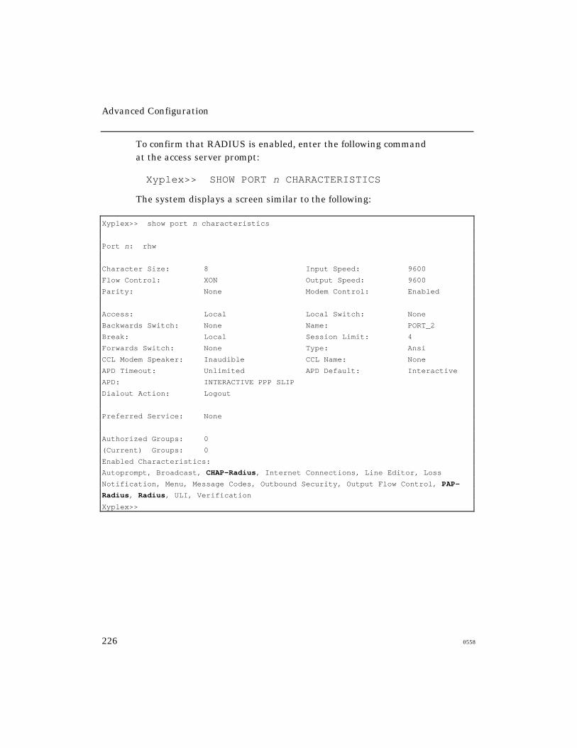
Advanced Configuration
226 0558
To confirm that RADIUS is enabled, enter the following commandat the access server prompt:
Xyplex>> SHOW PORT n CHARACTERISTICS
The system displays a screen similar to the following:
Xyplex>> show port n characteristics
Port n: rhw
Character Size: 8 Input Speed: 9600
Flow Control: XON Output Speed: 9600
Parity: None Modem Control: Enabled
Access: Local Local Switch: None
Backwards Switch: None Name: PORT_2
Break: Local Session Limit: 4
Forwards Switch: None Type: Ansi
CCL Modem Speaker: Inaudible CCL Name: None
APD Timeout: Unlimited APD Default: Interactive
APD: INTERACTIVE PPP SLIP
Dialout Action: Logout
Preferred Service: None
Authorized Groups: 0
(Current) Groups: 0
Enabled Characteristics:
Autoprompt, Broadcast, CHAP-Radius, Internet Connections, Line Editor, Loss
Notification, Menu, Message Codes, Outbound Security, Output Flow Control, PAP-
Radius, Radius, ULI, Verification
Xyplex>>
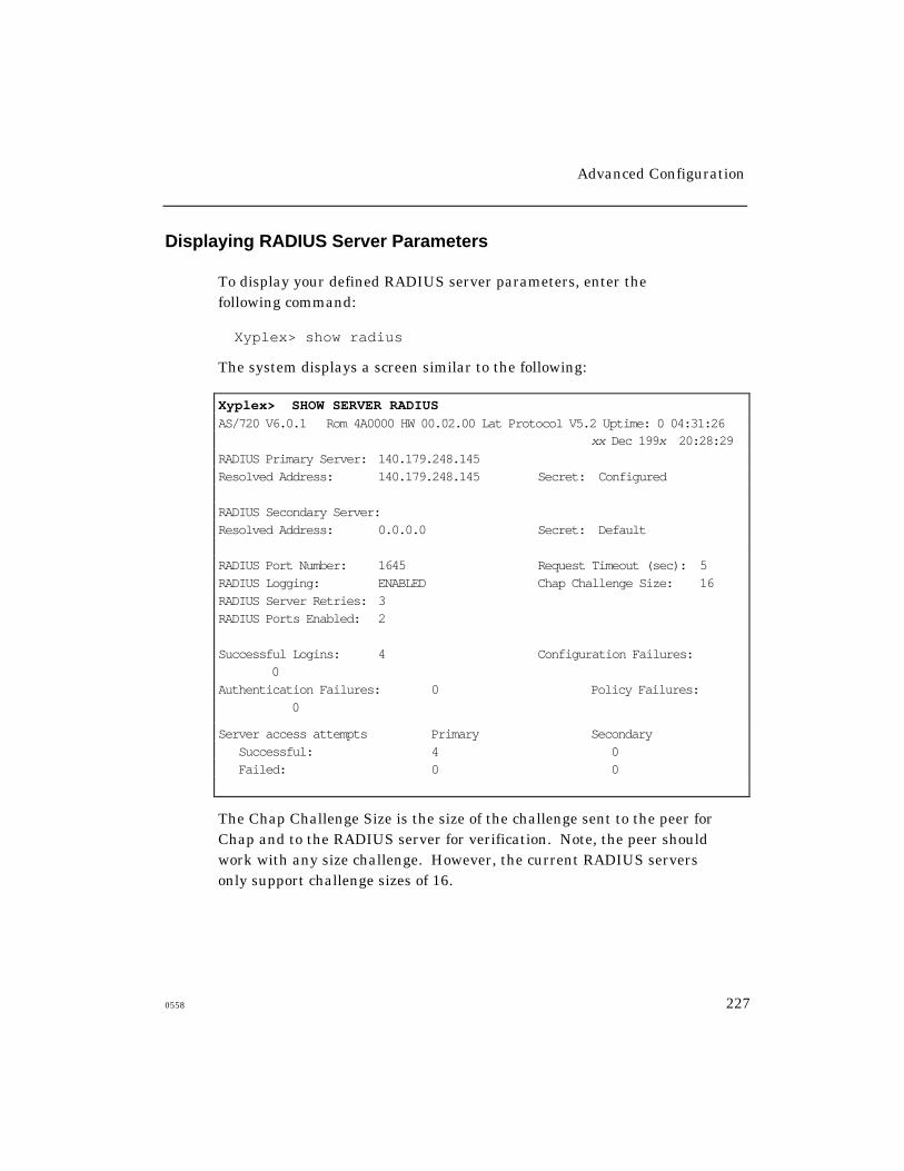
Advanced Configuration
0558 227
Displaying RADIUS Server Parameters
To display your defined RADIUS server parameters, enter thefollowing command:
Xyplex> show radius
The system displays a screen similar to the following:
Xyplex> SHOW SERVER RADIUS
AS/720 V6.0.1 Rom 4A0000 HW 00.02.00 Lat Protocol V5.2 Uptime: 0 04:31:26xx Dec 199x 20:28:29
RADIUS Primary Server: 140.179.248.145Resolved Address: 140.179.248.145 Secret: Configured
RADIUS Secondary Server:Resolved Address: 0.0.0.0 Secret: Default
RADIUS Port Number: 1645 Request Timeout (sec): 5RADIUS Logging: ENABLED Chap Challenge Size: 16RADIUS Server Retries: 3RADIUS Ports Enabled: 2
Successful Logins: 4 Configuration Failures: 0
Authentication Failures: 0 Policy Failures: 0
Server access attempts Primary Secondary Successful: 4 0 Failed: 0 0
The Chap Challenge Size is the size of the challenge sent to the peer forChap and to the RADIUS server for verification. Note, the peer shouldwork with any size challenge. However, the current RADIUS serversonly support challenge sizes of 16.
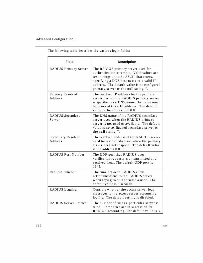
Advanced Configuration
228 0558
The following table describes the various login fields:
Field Description
RADIUS Primary Server The RADIUS primary server used forauthentication attempts. Valid values aretext strings up to 51 ASCII characters,specifying a DNS host name or a valid IPaddress. The default value is no configuredprimary server or the null string “”.
Primary ResolvedAddress
The resolved IP address for the primaryserver. When the RADIUS primary serveris specified as a DNS name, the name mustbe resolved to an IP address. The defaultvalue is the address 0.0.0.0.
RADIUS SecondaryServer
The DNS name of the RADIUS secondaryserver used when the RADIUS primaryserver is not used or available. The defaultvalue is no configured secondary server orthe null string “”.
Secondary ResolvedAddress
The resolved address of the RADIUS serverused for user verification when the primaryserver does not respond. The default valueis the address 0.0.0.0.
RADIUS Port Number The UDP port that RADIUS userverification requests are transmitted andreceived from. The default UDP port is1645.
Request Timeout The time between RADIUS clientretransmissions to the RADIUS serverwhen trying to authenticate a user. Thedefault value is 5 seconds.
RADIUS Logging Controls whether the access server logsmessages to the access server accountinglog file. The default setting is disabled.
RADIUS Server Retries The number of times a particular server istried. These tries are in succession forRADIUS accounting. The default value is 3.

Advanced Configuration
0558 229
RADIUS Ports Enabled A list of ports that have RADIUS enabledfor either interactive or PPP use.
Successful Logins Number of successful logins.
Authentication Failures Number of rejections returned by theRADIUS server.
Configuration Failures* Number of failures returned by theRADIUS server due to incorrect valuesbeing entered for supported attributes.
Policy Failures* Number of failures returned by theRADIUS server due to a port being hard-configured for one type of RADIUS service-type, but the RADIUS server returned adifferent service-type.
Policy failures also occur when the service-type selected by APD or Solicitation doesnot match the service-type returned by theRADIUS server.
Successful Server AccessAttempts
The number of times the RADIUS serverand the access server successfullyexchanged messages. This is the combinedcount for Authentication and Accountingmessages.
Failed Server AccessAttempts
The number of times the secondaryRADIUS server and the access server failedto exchange messages.
* These failures are local failures only and are not attributed to theRADIUS server.
Monitoring RADIUS During Login
To monitor the port login process during login, define the followingvalues and then reboot the access server.
Xyplex>> DEFINE RADIUS LOGGING ENABLEDXyplex>> DEFINE SERVER ACCOUNTING ENTRIES <1-1000>Xyplex>> DEFINE SERVER VERBOSE ACCOUNTING ENABLEDXyplex>> DEFINE SERVER VERBOSE PRIORITY 7

Advanced Configuration
230 0558
Outbound Port Security
The Outbound Port Security feature allows you to enable the RADIUS,Kerberos, SecurID, or simple port password security features on remoteor dynamic ports.
Outbound Port Security allows you to:
• Restrict access to telephone lines that connect to remote locations.It prevents the unauthorized use of dial-out lines and provides amonitoring trial (provided you have accounting enabled).
• Prevent unauthorized access to an async port of a device fromLAN users.
Without this feature, these security mechanisms do not apply toremote or dynamic ports. You can enable only one securitymechanism on a port. To enable the Outbound Port Securityfeature, use the following command:
DEFINE/SET PORT [port-list] OUTBOUNDSECURITY ENABLED
The default setting for this command is ENABLED. This is aprivileged command.
Radius Callback (Dialback)
Radius Callback (Dialback) provides automatic dialback capability to users
logging into a Xyplex port. The following actions occur during a typical
callback (Dialback) sequence:
1. The user dials into the Xyplex port and enters the Radius username and
password information.
2. If the username/password are authenticated by the Radius host, the
connecting modems hang up.
3. The Dialback process calls the originating modem.
4. The Radius username prompt appears again.
Advanced Configuration
0558 231
5. You must re-enter the same username. If the usernames match, the
connection continues.
If the user enters a username that does not match the first one, the port is
automatically logged out.
Callback Modes
Support is provided for Radius Callback (Dialback) in the following modes:
• Callback-Login - consists of a dialback followed by a connection to adedicated host specified in the Radius users file.
• Callback-Framed-User - consists of a dialback followed by PPP
negotiation with the Xyplex Access Server.
• Livingston V1.16 and all versions of Merit send back a Framed-
Compression = None if Framed-Compression = Van-Jacobson-TCP-
IP has not been included in the user’s entry in the Users file.
Xyplex access server code does not flag Framed-Compression as
unsupported and allows authentication to continue.
Callback-Login Parameters
Parameters for Callback-login are specified in the Radius users file. The
following shows a typical Callback-Login entry in the users file.
bob Password = "secret"
Service-Type = Callback-Login-User,
Login-IP-Host = 140.210.211.99,
Login-Service = Telnet
In this example, bob is the username, secret is the password. The
Service-Type is Callback-Login-User. The Login-IP-Host is IP address
for the host machine. The Login-service is Telnet.
Advanced Configuration
232 0558
NOTE: The Service-Type must be Callback-Login-User for Livingston
Radius implementations (as opposed to Login-User for non-
dialback logins). For Merit Radius implementations Callback-
Login is used for dialback and Login is used for non-dialback
logins. Refer to the radius dictionary file for specific information.
Callback-Framed User Mode
Parameters for Callback-Framed User Mode are specified in the Radius
users file. The following shows a typical Callback-Framed User entry in
the users file.
sue Password = "secret"
Service-Type = Callback-Framed-User,
Framed-Protocol = PPP
Framed-IP-Address = 140.210.211.99,
Framed-Compression = Van-Jacobson-TCP-IP
In this example, sue is the username, secret is the password. The
Service-Type is Callback-Framed-User. The Framed-Protocol is PPP.
The IP Address to use remotely for PPP is 140.210.211.99. The Framed-
Compression type is Van-Jacobson-TCP-IP.
NOTE: The Service-Type must be Callback-Framed-User for
Livingston Radius implementations (as opposed to Framed-
User for non-dialback logins) . For Merit Radius
implementations Callback-Framed is used for dialback and
Framed is used for non-dialback logins. Refer to the radius
dictionary file for specific information.
Advanced Configuration
0558 233
Configuration Tips
Follow these tips and guidelines to configure Radius Callback:
• Dialback provides you with two configuration choices. You can
− define dialback on the port along with Radius and then limit the
users who connect to this port to do Radius and dialback
− just define Radius on the port.
The Radius callback software automatically enables dialback on the
port, for that login session only, upon seeing the "Callback" string in
the radius users file. If you choose to configure this way, the port is still
available for regular Radius interactive users (Note: The Radius Spec
does not provide for support of Callback (Dialback) for interactive
users).
• The port must be set to access "dynamic".
• The Dialback process connects to the originating modem. In
testing, it has taken up to 25 seconds for the reconnection to
occur, once the re-dial has taken place. By default the dialback
timeout is set at 20 seconds. Xyplex Networks suggests that you
reset it to at least 25 seconds.
To reset the dialback timeout, enter
define port port-number dialback timeout 25
• The dialback login script should include the #pause 5. This line must
appear before the line #atdt.
• To display Dialback-Login or Dialback-Framed User login information,
set the accounting log to verbose priority 7.
Advanced Configuration
234 0558
• The modem attached to the COM port of the PC must be set to answer
mode. Most modems from the factory have auto-answer disabled. This
means that the modem will not answer an incoming call.
To enable auto-answer (on most Hayes compatible modems), you need toissue an ats0=1 (or higher). This sets the modem to answer after 1
ring. Save the configuration on the modem. For additional information
refer to the documentation that accompanied your modem.
Supported Platforms
Radius Callback (Dialback) is supported on:
• Chameleon, V4.6
• Stampede Remote Office ,V2.0, with Connect dialog box enabled
(although Xyplex Networks has officially ended its support for
Stampede Remote Office as of V6.0.3)
These platforms provides a terminal(tty) window that stays active after the
first dialback hangup occurs thereby allowing the login user to be promptedfor the second Enter username prompt.
Unsupported Platforms
Radius Callback (Dialback) is not supported on:
• Windows' 95 Dial-Up Networking
• FTP Software OnNet2.0
Windows' 95 Dial-Up Networking and FTP Software OnNet2.0 do not keep
a terminal(tty)window active, and there is no apparent option to keep it
active, after the modem hangs up to perform dialback. Windows 95 and
OnNet 2.0 consider this a disconnection and end the session. This preventsthe login user from receiving the second Enter username prompt.

Advanced Configuration
0558 235
Unsupported Attributes
The Radius CallBack (Dialback) software included in V6.0.4 upgrade does
not support
• Callback-Number
• Callback-ID
PPP Negotiations When a Port Has PPP and RADIUS Enabled
On a port with PPP, RADIUS, and an IDLE TIMEOUT enabled, theIDLE TIMEOUT begins counting down as soon as the port detects amodem signal.
Supported RADIUS Authentication Attributes
Some attributes appear in start records and the majority appear in stop
records (a few also appear in acct-on and acct-off records). RADIUS allows
most authentication and configuration attributes to be logged.
NOTE: These attributes will not be logged if RADIUS Accounting is set to
LIMITED instead of ENABLED.
Limited vs Enabled
If ENABLED is the selected option, all supported attributes are displayed in
the log. When LIMITED is the selected option, only the required attributes
are displayed in the log.
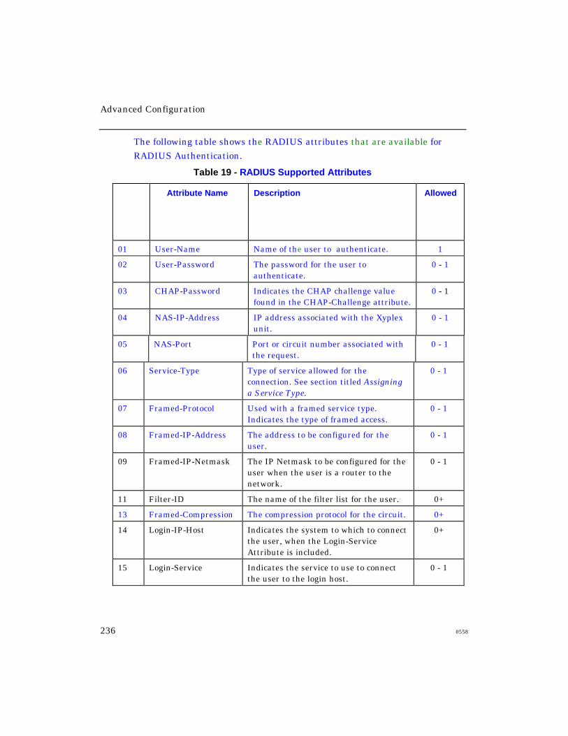
Advanced Configuration
236 0558
The following table shows the RADIUS attributes that are available for
RADIUS Authentication.
Table 19 - RADIUS Supported Attributes
I
d
#
Attribute Name Description Allowed
01 User-Name Name of the user to authenticate. 1
02 User-Password The password for the user toauthenticate.
0 - 1
03 CHAP-Password Indicates the CHAP challenge valuefound in the CHAP-Challenge attribute.
0 - 1
04 NAS-IP-Address IP address associated with the Xyplexunit.
0 - 1
05 NAS-Port Port or circuit number associated withthe request.
0 - 1
06 Service-Type Type of service allowed for theconnection. See section titled Assigninga Service Type.
0 - 1
07 Framed-Protocol Used with a framed service type.Indicates the type of framed access.
0 - 1
08 Framed-IP-Address The address to be configured for theuser.
0 - 1
09 Framed-IP-Netmask The IP Netmask to be configured for theuser when the user is a router to thenetwork.
0 - 1
11 Filter-ID The name of the filter list for the user. 0+
13 Framed-Compression The compression protocol for the circuit. 0+
14 Login-IP-Host Indicates the system to which to connectthe user, when the Login-ServiceAttribute is included.
0+
15 Login-Service Indicates the service to use to connectthe user to the login host.
0 - 1
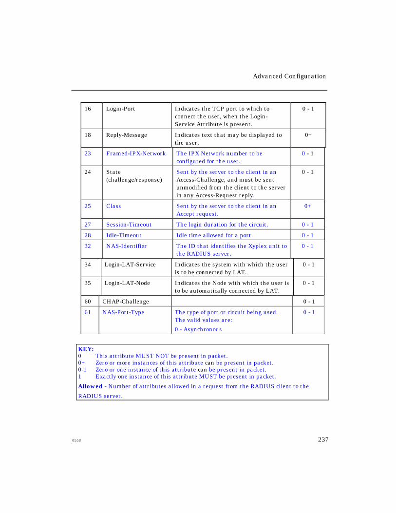
Advanced Configuration
0558 237
16 Login-Port Indicates the TCP port to which toconnect the user, when the Login-Service Attribute is present.
0 - 1
18 Reply-Message Indicates text that may be displayed tothe user.
0+
23 Framed-IPX-Network The IPX Network number to beconfigured for the user.
0 - 1
24 State(challenge/response)
Sent by the server to the client in anAccess-Challenge, and must be sentunmodified from the client to the serverin any Access-Request reply.
0 - 1
25 Class Sent by the server to the client in anAccept request.
0+
27 Session-Timeout The login duration for the circuit. 0 - 1
28 Idle-Timeout Idle time allowed for a port. 0 - 1
32 NAS-Identifier The ID that identifies the Xyplex unit tothe RADIUS server.
0 - 1
34 Login-LAT-Service Indicates the system with which the useris to be connected by LAT.
0 - 1
35 Login-LAT-Node Indicates the Node with which the user isto be automatically connected by LAT.
0 - 1
60 CHAP-Challenge 0 - 1
61 NAS-Port-Type The type of port or circuit being used.The valid values are:
0 - Asynchronous
0 - 1
KEY:0 This attribute MUST NOT be present in packet.0+ Zero or more instances of this attribute can be present in packet.0-1 Zero or one instance of this attribute can be present in packet.1 Exactly one instance of this attribute MUST be present in packet.
Allowed - Number of attributes allowed in a request from the RADIUS client to the
RADIUS server.

Advanced Configuration
238 0558
Defining RADIUS Accounting
This section describes the new remote access user accounting feature, called
RADIUS Accounting. RADIUS Accounting is a client/server account
logging scheme that allows you to log user account information to a remote
server in a per client file. The file or record can contain information such as
the user who logged in, the duration of the session, and the number of
bytes/packets that were processed by the Access Server.
The use of RADIUS Accounting solves the problems associated with local
storage of large numbers of records. It also provides a method for billing
customers for account usage.
NOTE: RADIUS Accounting is a developing standard that is vendor
extensible by design, including a provision for vendor specific
extensions. This allows for greater expandability of accounting
information in the future.
At initialization time, the system sends a RADIUS Accounting
query out to the network (even if RADIUS Accounting is disabled).
The system queries the DNS server on every RADIUS request for
IP resolution. If the DNS server is down at initialization time,
then another query is done for each authentication if the RADIUS
IP resolved address is 0.0.0.0.
For further information about RADIUS Accounting, refer to RadiusAccounting RFC 2059 (April 1997) for the requirements of theRADIUS implementation.
RADIUS Accounting Prerequisites
To use RADIUS Accounting on an access server, you need the following:
• Support for Internet Draft RADIUS Accounting on a RADIUS
Authentication Server in the network. (This is usually done with
portable code for the RADIUS Accounting feature installed on the
RADIUS Authentication Server.)

Advanced Configuration
0558 239
• Interoperation with a RADIUS server, such as a Merit RADIUS server.
• Minimum of 3 MB of memory.
Setting Up RADIUS Accounting
To setup RADIUS Accounting on your access server:
1. Make a copy of your parameter file. Xyplex Networks recommends that
you copy the existing file to a file with an “.old” extension.
2. Insert the flash card containing the load image and reboot the
access server.
3. Enable RADIUS on the access server, using the following command:
define server radius enabled
4. Enable Xyplex Accounting at a priority level 7, using the
following commands:
define server accounting entries 255init delay 0define server verbose accounting enableddefine server verbose priority 7define server radius logging enabled
Xyplex Accounting is independent of RADIUS Accounting and
therefore able to log all events including failures. This allows
you to troubleshoot RADIUS authentication and RADIUS
accounting problems.
5. Verify that the parameter state has gone to “current,” using the
following command:
monitor parameter server
6. Reboot the access server.
init delay 0
Advanced Configuration
240 0558
Defining a UDP Port Number
To define a UDP port number used by the RADIUS client and server for
communication, use the following command:
DEFINE/SET [SERVER] RADIUS ACCOUNTING PORT n
The default value is 1646.
Defining the RADIUS Accounting Logging Attempts Limits
To define the number of times that the access server attempts to log the
accounting record to both the primary and secondary servers before
giving up and failing, use the following command:
DEFINE/SET [SERVER] RADIUS ACCOUNTING ATTEMPTS n
A backoff algorithm is implemented to delay for a period of time between
these attempts. The default value is 5 attempts.
Defining RADIUS Accounting for Port Logins and Logouts
To enable RADIUS Accounting for port logins and logouts, use the
following command:
DEFINE/SET PORT n RADIUS ACCOUNTING {ENABLED|DISABLED}LOG PORT n
Note that even though it is enabled, nothing is logged until an
authentication protocol is enabled.
Advanced Configuration
0558 241
RADIUS Accounting Client Operation
During the authentication process, when RADIUS Accounting is enabled
on an appropriate port, an accounting request (a start request) is sent
before login to the RADIUS Accounting process begins. As a result of the
start request, a start record containing the following is created for each
user session:
• User-name
• NAS-Identifier
• NAS-IP-Address
• NAS-Port
• NAS-Port-Type
• Service-Type
• Acct-Status-Type
• Acct-Delay-Time
• Acct-Session-Id
• Acct-Authentication
The majority of the accounting record information appears in the stop record.
The stop record is created when the port is logged out, provided that a
matching start record was previously sent. The information in the stop record
includes everything in the start record, and additional information, such as
session time and bytes/packets transferred.
There are two special records that are logged for RADIUS Accounting.
• Accounting-on. This record is logged when the access server is
first booted.
• Accounting-off. This record is logged, if possible, when the access server
is shutdown.

Advanced Configuration
242 0558
These records only contain the Session-Id, Acct-Status-Type, and NAS-IP-
Address. Since these accounting requests only relate to the access server
using the protocol and not to accounting on a specific port, they are only
attempted if the RADIUS protocol is enabled.
Accounting Retry and Backoff Timer Process
RADIUS Accounting has built-in timeout and retry capabilities. The
RADIUS Accounting feature logs the record to the remote server, when
possible. However, sending requests constantly and continually trying to
process them should be avoided. Therefore, this implementation of RADIUS
Accounting uses a two-part retry and backoff algorithm based on the
following configurable controls:
• The first part of the retry mechanism directly affects the communication
between the RADIUS client on the NAS and each RADIUS server. It is
the same retry functionality that RADIUS authentication uses. The
NAS client waits a configurable amount of time (Request Timeout in
seconds) for an acknowledgment after it sends an accounting request to
a server. If the timeout period occurs, it retries the server again. After
three configurable “server retries”, it proceeds to the next (secondary)
server in the list. The secondary server is then tried in the same way,
provided that the servers are configured. RADIUS Servers configured
on the NAS with the default value 0.0.0.0 are not used.
• The second piece of the retry mechanism involves the available
primary and secondary RADIUS servers. After sending requests
to all the configured servers and failing to get a timely response,
the request waits a period of time before starting over with the
first server in the list and re-sending the request. The period of
time that it waits is based on the configurable request timeout and
the number of attempts that have been made to send this request
to all the servers.
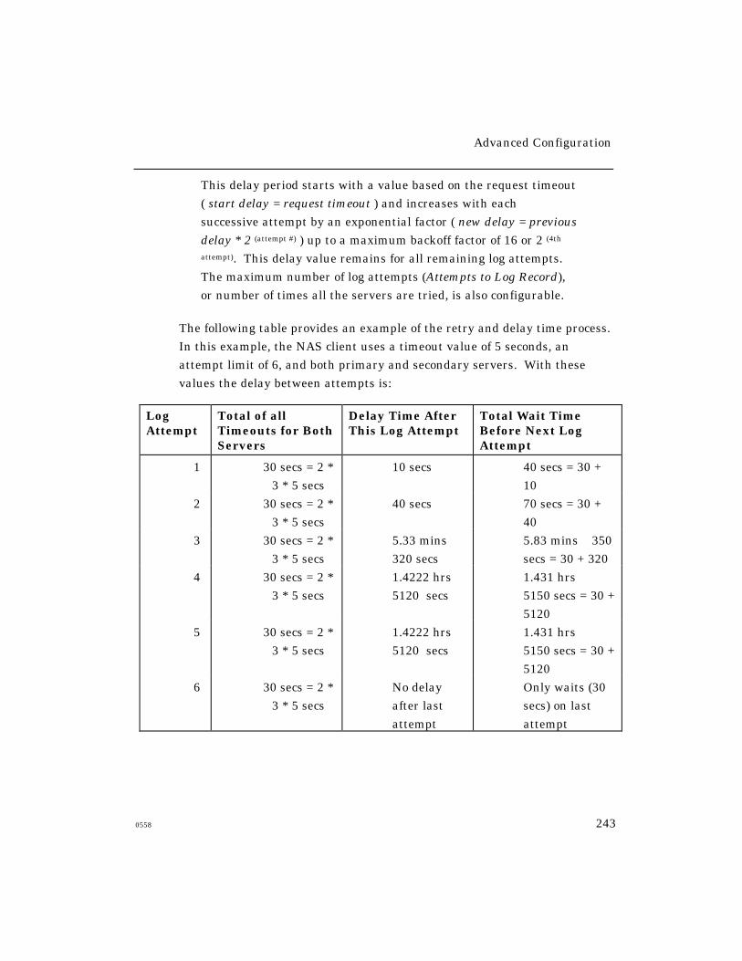
Advanced Configuration
0558 243
This delay period starts with a value based on the request timeout
( start delay = request timeout ) and increases with each
successive attempt by an exponential factor ( new delay = previous
delay ∗ 2 (attempt #) ) up to a maximum backoff factor of 16 or 2 (4th
attempt). This delay value remains for all remaining log attempts.
The maximum number of log attempts (Attempts to Log Record),
or number of times all the servers are tried, is also configurable.
The following table provides an example of the retry and delay time process.
In this example, the NAS client uses a timeout value of 5 seconds, an
attempt limit of 6, and both primary and secondary servers. With these
values the delay between attempts is:
LogAttempt
Total of allTimeouts for BothServers
Delay Time AfterThis Log Attempt
Total Wait TimeBefore Next LogAttempt
1 30 secs = 2 *
3 * 5 secs
10 secs 40 secs = 30 +
10
2 30 secs = 2 *
3 * 5 secs
40 secs 70 secs = 30 +
40
3 30 secs = 2 *
3 * 5 secs
5.33 mins ≅320 secs
5.83 mins ≅ 350
secs = 30 + 320
4 30 secs = 2 *
3 * 5 secs
1.4222 hrs ≅5120 secs
1.431 hrs ≅5150 secs = 30 +
5120
5 30 secs = 2 *
3 * 5 secs
1.4222 hrs ≅5120 secs
1.431 hrs ≅5150 secs = 30 +
5120
6 30 secs = 2 *
3 * 5 secs
No delay
after last
attempt
Only waits (30
secs) on last
attempt
Advanced Configuration
244 0558
Canceling RADIUS Requests
Once a RADIUS request is added to a respective process queues, you
may want to “cancel” the request and prevent the RADIUS client from
retrying a server that cannot or does not respond. To do this use the
following command:
CLEAR/PURGE SERVER RADIUS {AUTHENTICATION|ACCOUNTING} {n|ALL}
The request id, ‘n’, is obtained by viewing information in the server
accounting log on the access server, provided that server accounting and
RADIUS logging (not RADIUS account logging) are enabled. All
outstanding requests may be eliminated if ‘ALL’ is specified.
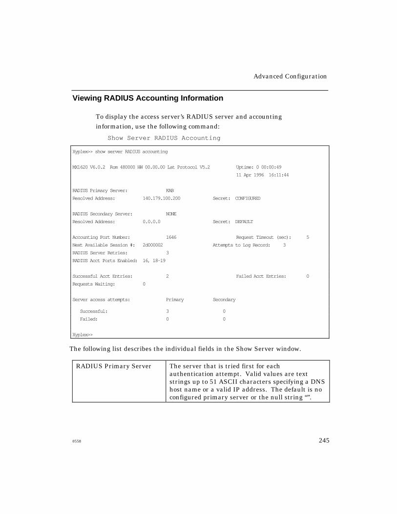
Advanced Configuration
0558 245
Viewing RADIUS Accounting Information
To display the access server’s RADIUS server and accounting
information, use the following command:
Show Server RADIUS Accounting
Xyplex>> show server RADIUS accounting
MX1620 V6.0.2 Rom 480000 HW 00.00.00 Lat Protocol V5.2 Uptime: 0 00:00:49
11 Apr 1996 16:11:44
RADIUS Primary Server: KAB
Resolved Address: 140.179.100.200 Secret: CONFIGURED
RADIUS Secondary Server: NONE
Resolved Address: 0.0.0.0 Secret: DEFAULT
Accounting Port Number: 1646 Request Timeout (sec): 5
Next Available Session #: 2d000002 Attempts to Log Record: 3
RADIUS Server Retries: 3
RADIUS Acct Ports Enabled: 16, 18-19
Successful Acct Entries: 2 Failed Acct Entries: 0
Requests Waiting: 0
Server access attempts: Primary Secondary
Successful: 3 0
Failed: 0 0
Xyplex>>
The following list describes the individual fields in the Show Server window.
RADIUS Primary Server The server that is tried first for eachauthentication attempt. Valid values are textstrings up to 51 ASCII characters specifying a DNShost name or a valid IP address. The default is noconfigured primary server or the null string “”.
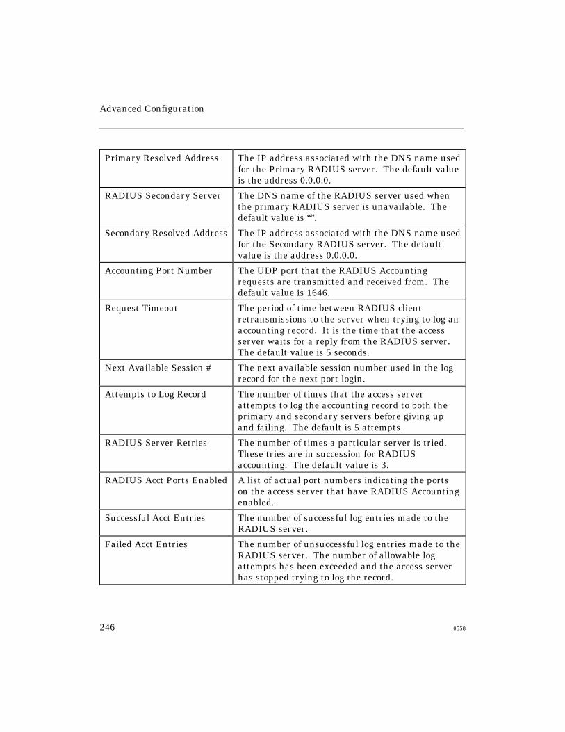
Advanced Configuration
246 0558
Primary Resolved Address The IP address associated with the DNS name usedfor the Primary RADIUS server. The default valueis the address 0.0.0.0.
RADIUS Secondary Server The DNS name of the RADIUS server used whenthe primary RADIUS server is unavailable. Thedefault value is “”.
Secondary Resolved Address The IP address associated with the DNS name usedfor the Secondary RADIUS server. The defaultvalue is the address 0.0.0.0.
Accounting Port Number The UDP port that the RADIUS Accountingrequests are transmitted and received from. Thedefault value is 1646.
Request Timeout The period of time between RADIUS clientretransmissions to the server when trying to log anaccounting record. It is the time that the accessserver waits for a reply from the RADIUS server.The default value is 5 seconds.
Next Available Session # The next available session number used in the logrecord for the next port login.
Attempts to Log Record The number of times that the access serverattempts to log the accounting record to both theprimary and secondary servers before giving upand failing. The default is 5 attempts.
RADIUS Server Retries The number of times a particular server is tried.These tries are in succession for RADIUSaccounting. The default value is 3.
RADIUS Acct Ports Enabled A list of actual port numbers indicating the portson the access server that have RADIUS Accountingenabled.
Successful Acct Entries The number of successful log entries made to theRADIUS server.
Failed Acct Entries The number of unsuccessful log entries made to theRADIUS server. The number of allowable logattempts has been exceeded and the access serverhas stopped trying to log the record.
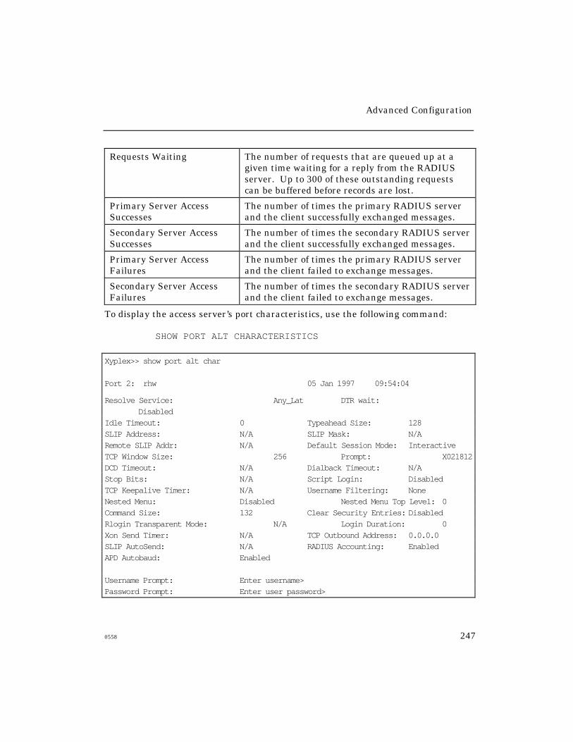
Advanced Configuration
0558 247
Requests Waiting The number of requests that are queued up at agiven time waiting for a reply from the RADIUSserver. Up to 300 of these outstanding requestscan be buffered before records are lost.
Primary Server AccessSuccesses
The number of times the primary RADIUS serverand the client successfully exchanged messages.
Secondary Server AccessSuccesses
The number of times the secondary RADIUS serverand the client successfully exchanged messages.
Primary Server AccessFailures
The number of times the primary RADIUS serverand the client failed to exchange messages.
Secondary Server AccessFailures
The number of times the secondary RADIUS serverand the client failed to exchange messages.
To display the access server’s port characteristics, use the following command:
SHOW PORT ALT CHARACTERISTICS
Xyplex>> show port alt char
Port 2: rhw 05 Jan 1997 09:54:04
Resolve Service: Any_Lat DTR wait:Disabled
Idle Timeout: 0 Typeahead Size: 128SLIP Address: N/A SLIP Mask: N/ARemote SLIP Addr: N/A Default Session Mode: InteractiveTCP Window Size: 256 Prompt: X021812DCD Timeout: N/A Dialback Timeout: N/AStop Bits: N/A Script Login: DisabledTCP Keepalive Timer: N/A Username Filtering: NoneNested Menu: Disabled Nested Menu Top Level: 0Command Size: 132 Clear Security Entries: DisabledRlogin Transparent Mode: N/A Login Duration: 0Xon Send Timer: N/A TCP Outbound Address: 0.0.0.0SLIP AutoSend: N/A RADIUS Accounting: EnabledAPD Autobaud: Enabled
Username Prompt: Enter username>Password Prompt: Enter user password>
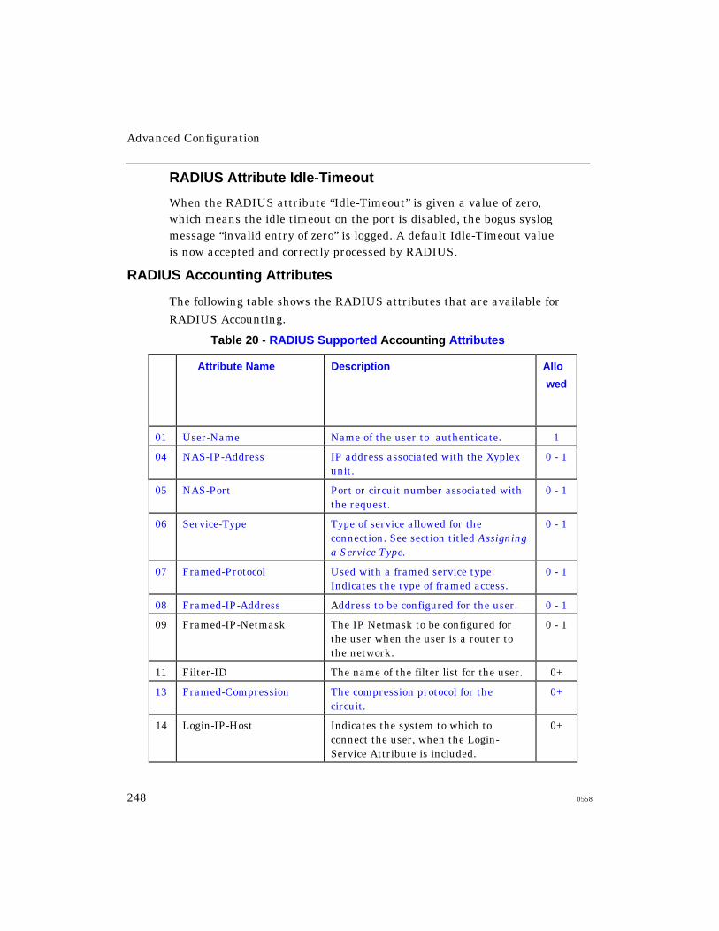
Advanced Configuration
248 0558
RADIUS Attribute Idle-Timeout
When the RADIUS attribute “Idle-Timeout” is given a value of zero,which means the idle timeout on the port is disabled, the bogus syslogmessage “invalid entry of zero” is logged. A default Idle-Timeout valueis now accepted and correctly processed by RADIUS.
RADIUS Accounting Attributes
The following table shows the RADIUS attributes that are available for
RADIUS Accounting.
Table 20 - RADIUS Supported Accounting Attributes
I
d
#
Attribute Name Description Allo
wed
01 User-Name Name of the user to authenticate. 1
04 NAS-IP-Address IP address associated with the Xyplexunit.
0 - 1
05 NAS-Port Port or circuit number associated withthe request.
0 - 1
06 Service-Type Type of service allowed for theconnection. See section titled Assigninga Service Type.
0 - 1
07 Framed-Protocol Used with a framed service type.Indicates the type of framed access.
0 - 1
08 Framed-IP-Address Address to be configured for the user. 0 - 1
09 Framed-IP-Netmask The IP Netmask to be configured forthe user when the user is a router tothe network.
0 - 1
11 Filter-ID The name of the filter list for the user. 0+
13 Framed-Compression The compression protocol for thecircuit.
0+
14 Login-IP-Host Indicates the system to which toconnect the user, when the Login-Service Attribute is included.
0+

Advanced Configuration
0558 249
15 Login-Service Indicates the service to use to connectthe user to the login host.
0 - 1
16 Login-Port Indicates the TCP port to which toconnect the user, when the Login-Service Attribute is present.
0 - 1
23 Framed-IPX-Network The IPX Network number to beconfigured for the user.
0 - 1
25 Class Sent by the server to the client in anAccept request.
0+
27 Session-Timeout The login duration for the circuit. 0 - 1
28 Idle-Timeout Idle time allowed for a port. 0 - 1
32 NAS-Identifier The ID that identifies the Xyplex unitto the RADIUS server.
0 - 1
34 Login-LAT-Service Indicates the system with which theuser is to be connected by LAT.
0 - 1
35 Login-LAT-Node Indicates the Node with which the useris to be automatically connected byLAT.
0 - 1
40 Acct-Status-Type Type of accounting record:1 - start record2 - stop record7 - acct-on8 - acct-off
1
41 Acct-Delay-Time Any delays, measured in seconds, intransmitting to the server.
0 - 1
42 Acct-Input-Octets The number of octets inbound to theport or circuit. Only in stop records ifgreater than 0.
0 - 1
43 Acct-Output-Octets The number of octets outbound to theport or circuit. Only in stop records ifgreater than 0.
0 - 1
44 Acct-Session-Id Identifies paired logging records in asession (acct-on/acct-off, start/stop)
1
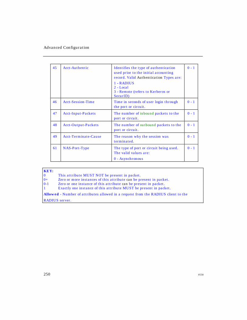
Advanced Configuration
250 0558
45 Acct-Authentic Identifies the type of authenticationused prior to the initial accountingrecord. Valid Authentication Types are:
1 - RADIUS2 - Local3 - Remote (refers to Kerberos orSecurID)
0 - 1
46 Acct-Session-Time Time in seconds of user login throughthe port or circuit.
0 - 1
47 Acct-Input-Packets The number of inbound packets to theport or circuit.
0 - 1
48 Acct-Output-Packets The number of outbound packets to theport or circuit.
0 - 1
49 Acct-Terminate-Cause The reason why the session wasterminated.
0 - 1
61 NAS-Port-Type The type of port or circuit being used.The valid values are:
0 - Asynchronous
0 - 1
KEY:0 This attribute MUST NOT be present in packet.0+ Zero or more instances of this attribute can be present in packet.0-1 Zero or one instance of this attribute can be present in packet.1 Exactly one instance of this attribute MUST be present in packet.
Allowed - Number of attributes allowed in a request from the RADIUS client to the
RADIUS server.
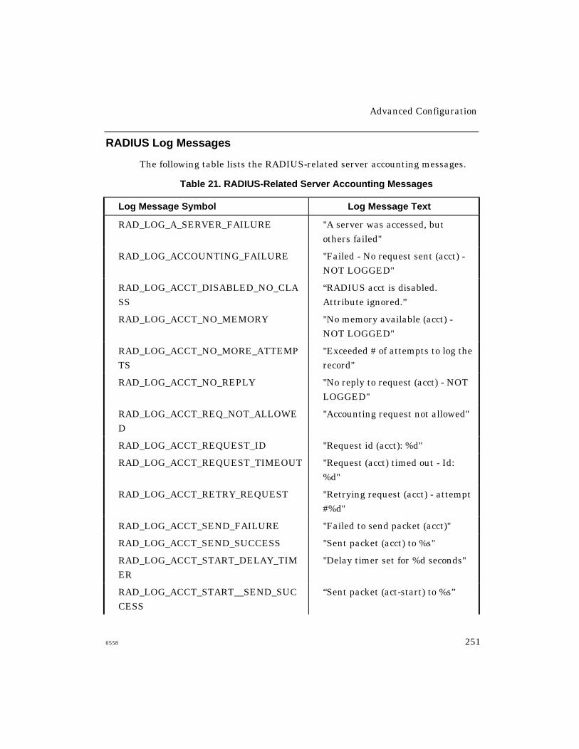
Advanced Configuration
0558 251
RADIUS Log Messages
The following table lists the RADIUS-related server accounting messages.
Table 21. RADIUS-Related Server Accounting Messages
Log Message Symbol Log Message Text
RAD_LOG_A_SERVER_FAILURE "A server was accessed, but
others failed"
RAD_LOG_ACCOUNTING_FAILURE "Failed - No request sent (acct) -
NOT LOGGED"
RAD_LOG_ACCT_DISABLED_NO_CLA
SS
“RADIUS acct is disabled.
Attribute ignored.”
RAD_LOG_ACCT_NO_MEMORY "No memory available (acct) -
NOT LOGGED"
RAD_LOG_ACCT_NO_MORE_ATTEMP
TS
"Exceeded # of attempts to log the
record"
RAD_LOG_ACCT_NO_REPLY "No reply to request (acct) - NOT
LOGGED"
RAD_LOG_ACCT_REQ_NOT_ALLOWE
D
"Accounting request not allowed"
RAD_LOG_ACCT_REQUEST_ID "Request id (acct): %d"
RAD_LOG_ACCT_REQUEST_TIMEOUT "Request (acct) timed out - Id:
%d"
RAD_LOG_ACCT_RETRY_REQUEST "Retrying request (acct) - attempt
#%d"
RAD_LOG_ACCT_SEND_FAILURE "Failed to send packet (acct)"
RAD_LOG_ACCT_SEND_SUCCESS "Sent packet (acct) to %s"
RAD_LOG_ACCT_START_DELAY_TIM
ER
"Delay timer set for %d seconds"
RAD_LOG_ACCT_START__SEND_SUC
CESS
“Sent packet (act-start) to %s”

Advanced Configuration
252 0558
RAD_LOG_ACCT_STOP__SEND_SUCC
ESS
“Sent packet (act-stop) to %s”
RAD_LOG_ACCT_WAIT_TO_RETRY "Waiting to retry request (acct)"
RAD_LOG_ALL_ACCT_IDS_USED "All RADIUS (acct) ids used - wait
to send"
RAD_LOG_ALL_SERVERS_FAIL "All server accesses failed"
RAD_LOG_ATTRIB_CREATE_ERR "Error storing an attribute"
RAD_LOG_ATTRIB_FAILED "Failed on attribute - %d"
RAD_LOG_AUTH_CONTINUE_ON_FAI
L
“Trying another server on auth
failure”
RAD_LOG_AUTH_FAILED "Authentication failure - logging
out"
RAD_LOG_AUTH_NO_MEMORY "No memory available (auth) -
logging out"
RAD_LOG_AUTH_REQUEST_ID "Request id (auth): %d"
RAD_LOG_AUTH_REQUEST_TIMEOU
T
"Request (auth) timed out - Id:
%d"
RAD_LOG_AUTH_SEND_FAILURE "Failed to send packet (auth)"
RAD_LOG_AUTH_SEND_SUCCESS "Sent packet (auth) to %s"
RAD_LOG_BAD_ATTRIB_FOR_CONFIG "Invalid attribute for
configuration"
RAD_LOG_BAD_ATTRIB_VAL_LEN "Invalid attribute length"
RAD_LOG_BAD_ATTRIB_VALUE "Invalid/unsupported attribute
value"
RAD_LOG_CANCEL_ACCT_REQUEST "Request canceled (acct) - Id: %d"
RAD_LOG_CANCEL_AUTH_REQUEST "Request canceled (auth) - Id: %d"
RAD_LOG_CHAP_REQUEST "Challenge Authentication
request"
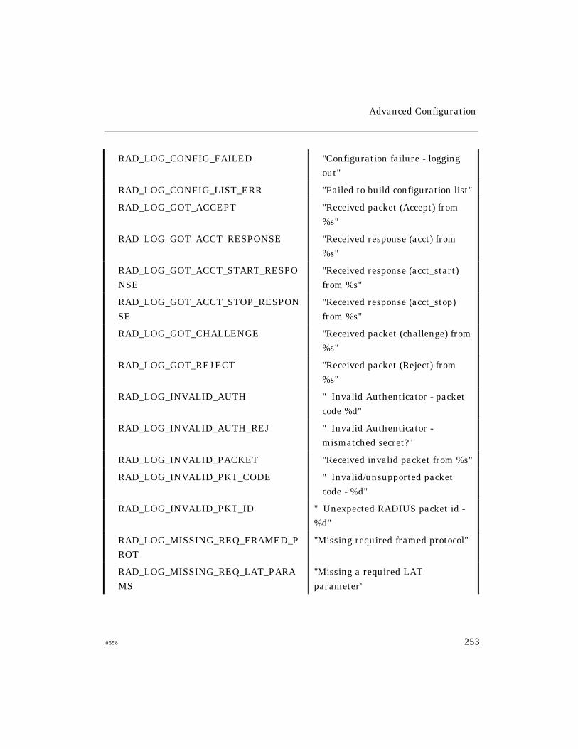
Advanced Configuration
0558 253
RAD_LOG_CONFIG_FAILED "Configuration failure - logging
out"
RAD_LOG_CONFIG_LIST_ERR "Failed to build configuration list"
RAD_LOG_GOT_ACCEPT "Received packet (Accept) from
%s"
RAD_LOG_GOT_ACCT_RESPONSE "Received response (acct) from
%s"
RAD_LOG_GOT_ACCT_START_RESPO
NSE
"Received response (acct_start)
from %s"
RAD_LOG_GOT_ACCT_STOP_RESPON
SE
"Received response (acct_stop)
from %s"
RAD_LOG_GOT_CHALLENGE "Received packet (challenge) from
%s"
RAD_LOG_GOT_REJECT "Received packet (Reject) from
%s"
RAD_LOG_INVALID_AUTH " Invalid Authenticator - packet
code %d"
RAD_LOG_INVALID_AUTH_REJ " Invalid Authenticator -
mismatched secret?"
RAD_LOG_INVALID_PACKET "Received invalid packet from %s"
RAD_LOG_INVALID_PKT_CODE " Invalid/unsupported packet
code - %d"
RAD_LOG_INVALID_PKT_ID " Unexpected RADIUS packet id -
%d"
RAD_LOG_MISSING_REQ_FRAMED_P
ROT
"Missing required framed protocol"
RAD_LOG_MISSING_REQ_LAT_PARA
MS
"Missing a required LAT
parameter"

Advanced Configuration
254 0558
RAD_LOG_MISSING_REQ_LOGIN_SER
VICE
"Missing required login service"
RAD_LOG_MISSING_REQ_SERVICE_T
YPE
"Missing required service type"
RAD_LOG_MISSING_REQ_TELNET_PA
RAMS
"Missing a required TELNET
parameter"
RAD_LOG_NO_PACKET_MEM "No memory for request packet"
RAD_LOG_NO_PASSWORD " No password specified"
RAD_LOG_NO_REC_BUFF_MEM "No memory for receive buffer"
RAD_LOG_NO_USERNAME " No username specified"
RAD_LOG_PAP_REQUEST " Password Authentication
request"
RAD_LOG_POLICY_FAILED "Policy failure - logging out"
RAD_LOG_SCRIPT_FAILURE "RADIUS script execution failure"
RAD_LOG_SECRET_CHANGED "Secret was changed - server %d"
RAD_LOG_SEND_CHAL_REPLY "Sent packet (response) to %s"
RAD_LOG_SERVICE_HINT_USED " Service type hint : %s"
RAD_LOG_SERVICE_NOT_CHOSEN "Service not type chosen"
RAD_LOG_TOO_MANY_PENDING_RE
QUESTS
"Too many pending requests (acct) -
NOT LOGGED"
RAD_LOG_UNKNOWN_COM_ATTR "Unexpected common attribute -
%d"
RAD_LOG_UNKNOWN_RAD_ATTR "Unexpected RADIUS attribute -
%d"
Advanced Configuration
0558 255
Getting Started - Kerberos
The basic steps for setting up Kerberos authentication follow:
1. Set up the Kerberos authentication servers.
2. Enable Kerberos authentication.
3. Configure Kerberos settings at the access server.
These steps are described in the following sections.
Set Up the Kerberos Authentication Servers
Follow the instructions in the documentation supplied with theKerberos software to install and set up the Kerberos Master and Serverhosts. Kerberos, the username can be a maximum of 119 characters(bytes), consisting of three sections of a maximum of 39 bytes each inthe form “username.instance@realm.” All displays which show theusername continue to print only the first 16 characters.
Enable Kerberos Authentication
You can set up an access server to authenticate users through either
Kerberos Version 4 or 5. Only one version can be running on the access
server. Use this command to enable Kerberos Version 4:
DEFINE/SET SERVER KERBEROS FOUR ENABLED
Use this command to enable Kerberos Version 5:
DEFINE/SET SERVER KERBEROS FIVE ENABLED
After issuing the command, and after the unit has saved its parameters,reboot the access server. (Issue the SHOW PARAMETER SERVER command to
verify that the parameter server is “current.”)

Advanced Configuration
256 0558
Configure Kerberos Settings
Use the following commands to set up the access server for
Kerberos authentication:
1. Specify the IP address of the Kerberos Master host; default: 0.0.0.0.
DEFINE/SET SERVER KERBEROS MASTER ip-address
2. Specify the IP address of the primary Kerberos Server. Default: 0.0.0.0.
DEFINE/SET SERVER KERBEROS PRIMARY SERVER ip-address
3. Specify the IP address of the alternate Kerberos Server; default: 0.0.0.0.
DEFINE/SET SERVER KERBEROS SECONDARY SERVER ip-address
4. Specify the name of the local Kerberos realm. A valid “realm-name” is acase-sensitive string of up to 40 characters, or NONE. Default: NONE.
DEFINE/SET SERVER KERBEROS REALM “realm-name”
5. Specify whether the server supports Kerberos; default: NONE.
DEFINE/SET SERVER KERBEROS SECURITY [LOGIN]
[NONE]
6. Specify the number of times the server queries (contacts) each Kerberos
Server host. You can specify a query-limit from 1 - 16. The default is 3.
DEFINE/SET SERVER KERBEROS QUERY LIMIT query-limit
7. Specify the Kerberos Password for the specified ports(s). When
you change a password, you are prompted to enter the old and
new passwords.
DEFINE PORT port-number USER KERBEROS PASSWORD
Advanced Configuration
0558 257
Kerberos Error Messages
The Kerberos Error Message feature allows you to specify the text inthe Kerberos 739 error message. This error message appears whenKerberos authentication fails due to a communications failure. Tospecify the text in the Kerberos 739 error message, use the followingcommand:
DEFINE/SET SERVER KERBEROS ERROR MESSAGE“character-string”
The “character-string” variable can contain up to 132 ASCIIcharacters. The character string must be enclosed in quotes. This isa privileged command.
The default character string is “Please contact yoursystem administrator.”
Idle Time Causing Kerberos Error 62 (Bad Password) andError 37 (Clock Skew Too Great)
This occurs after the user has entered a username, and then sits idle atthe “Enter User Password>” prompt for more then 5 minutes. Thiscauses the access server software to use incorrect time informationwhen communicating with the Kerberos authentication server. TheKerberos authentication server then fails to authenticate the userbecause the access server’s time is not synchronized with theauthentication server’s time.
The access server now uses the current time when sendingauthentication information to the Kerberos authentication server.
Advanced Configuration
258 0558
PPP User Authentication via Kerberos
Verify that Kerberos is setup correctly on the server and that it is
operational. Setup for master and primary server and enable on the server
ports. Check the Kerberos host to match realm name to access server. If one
access server is authenticating correctly using Kerberos 4, but another
server is not authenticating on that same server, then check the following:
• User is properly connecting to the server via PPP
• User name prompt is presented
• Userid is entered
• Password prompt is presented
If a valid password is entered, but the password is not authenticating, then
the solution is to add the REALM address to the access server. On the
server, "Where" means the realm-name which specifies the name of the
Kerberos realm to which the Master and Server hosts are associated. Valid
values are text strings of up to 40 ASCII characters long. NONE specifies
that no Kerberos Realm exists for this server. Kerberos REALM is case
sensitive and needs to be encased in quotes as follows: DEFINE SERVER
KERBEROS REALM "realm_name".
Logins Without Kerberos
Xyplex correctly displays the "Logins without Kerberos" field for a port that
has either Kerberos or PAP-Kerberos and Auto-Protocol Detect (APD)
enabled on it.
This is supported in software version V6-0-2 S2 and greater. PPP PAP -
Kerberos incremented the "Logins without Kerberos" counter once for each
of the carriage return (CR) required for APD. With Kerberos enabled on a
port, the "Show Server Kerberos" screens displayed that there were (n)
"Logins without Kerberos" when a single user logs onto a port once with the
APD interactive enabled. When ADP is disabled on the port, then the
counters are correct and one "Successful Login" and 0 "Logins without
Kerberos" is displayed.
Advanced Configuration
0558 259
Getting Started - SecurID Client Setup
The basic steps for setting up SecurID clients follow:
1. Set up the SecurID client at the UNIX host.
2. Install the Xyplex load image that contains the SecurID client.
3. Enable the SecurID feature at the access server.
4. Define server-related SecurID settings.
5. Set up ports to require SecurID authentication.
The following sections describe each step.
Configuring the SecurID Client at the UNIX host
Use the procedures described in the ACE/Server Manual from Security
Dynamics Technologies, Inc. to configure the access server as a SecurID
client. The main activities are:
• Installing the server software and getting it running
• Specifying clients
You must do some planning before you set up the SecurID client on an
access server. The values you specify for certain settings at the
ACE/Server(s) must match values for the same settings at the access
server. This is covered in more detail in “Define SecurID Settings”.
SecurID authentication allows a username of up to 32 characters. All
displays which show the username only display the first 16 characters.
Xyplex Network's SecurID client software is based on V1.1 of theACE/Server software supplied by Security Dynamics Technologies, Inc.The SecurID client software operates with ACE/Server host runningACE/Server software V1.1, or later.

Advanced Configuration
260 0558
Install Software that Supports the SecurID Client
Use the standard Xyplex software installation procedure, as described in
the Software Installation Guide for your load server type (UNIX,
VAX/VMS, or Xyplex load servers). After installing the software at the
load server, or on a local memory card or diskette, reboot the server so
that it runs the new load image.
Enable the SecurID Feature
To enable:
1. Enable the SecurID feature at the access server through this
command:
Xyplex>> define server securid enabled
The server responds with a message similar to:
-705- Change leaves approximately nnnnn bytes free.
If you are prompted with a “Not enough memory” warning, do not
reboot, but disable the feature. Disable the Define Server Securid.
2. Enter the Show Parameter Server display.
3. Make sure that the parameters are current (i.e., SecurID
is enabled).
4. Reboot the Access Server for the changes to take effect.
Xyplex>> init delay 0
Advanced Configuration
0558 261
Define SecurID Settings
At the access server, you must define the settings that enable the server to
communicate with ACE/Servers, and which control the way in which they
communicate. Most of the settings that you define apply only at the
SecurID client. However, the values for the acm_port and use_des (Server
SecurID Encryption Mode) settings must match the values you assign at the
ACE/Servers.
Define the Servers
Xyplex>> define server securid servern IP-address
Xyplex>> define server securid servern domain-name
The servern value refers to SERVER0 through SERVER4; the default
value for SERVER0 is the domain name SECURID_0. These values specify
the domain names for the primary and alternate ACE/Servers. If the first
ACE/Server does not respond to an authentication request, the access
server requests authentication from the alternate servers, in order, until it
receives a response. If no ACE/Servers respond, the access server repeats
the process, until it reaches the limit specified by the Server SecurID ACM
Max Retries setting.
When a user enters a domain name in an outbound connection request,
the server resolves (matches) the domain name to an IP address and
applies the result to the security table. The server checks its own
domain name database first, and then searches the domain name server
database. (A domain name server is a device that matches domain
names to IP addresses.)
Advanced Configuration
262 0558
ACM Base Timeout
Xyplex>> define server securid acmbasetimeout value
This setting controls the interval between prompts for a PASSCODE. A
valid value is a number between 1 and 10 seconds; the default is 3.
ACM Max Retries
Xyplex>> define server securid acmmaxretries value
This setting controls the number of times the access server tries to connect
to the ACE/Servers in its list (SERVER0 through SERVER4) when
authenticating a user. A valid value is a number between 1 and 10; the
default is 5.
ACM_Port
Xyplex>> define server securid acm_port udp-port-number
This setting specifies the destination UDP port number to use when
sending information to one or more ACE/Servers (SERVER0 through
SERVER4), when authenticating a user. A valid udp-port-number is a
number between 1 and 1023; the default is 755. This value must
match with the acm_port parameter at the ACE/Server(s) that the
access server uses.
Query Limit
Xyplex>> define server securid query limit limit
This setting controls the number of times that a user can enter a
PASSCODE incorrectly before the access server logs out the port. A valid
value is a number between 1 and 10; the default is 3.
Advanced Configuration
0558 263
Encryption Mode
Xyplex>> define server securid encryption mode value
The value you specify controls the type of encryption that the access server
uses when it communicates with an ACEserver. SecurID supports two
encryption methods:
• DES (Defense Encryption Standard)
• SDI BLOCK CIPHER (proprietary Security Dynamics Technologies,
Inc. encryption method).
The default method is DES.
Configure Ports to Require SecurID Authentication
After defining the server settings, use this command to specify which ports
require SecurID authentication:
DEFINE PORT port-list SECURID ENABLED
SecurID Failure
A port with SecurID, DYNAMIC ACCESS, and APD does not promptthe user for the SecurID username or passcode. The user is correctlyauthenticated via SecurID.
SecurID - Entering New PIN Mode
Truncation of a 7 or 8 digit PIN number no longer occurs. The field length
was changed to 16 digits. The 16-digit length was used because on a normal
login, the user can potentially enter up to 16 digits (e.g., 8 for the PIN and 8
for the Passcode).
Show Server Securid Display
Carriage returns are not counted as logins.
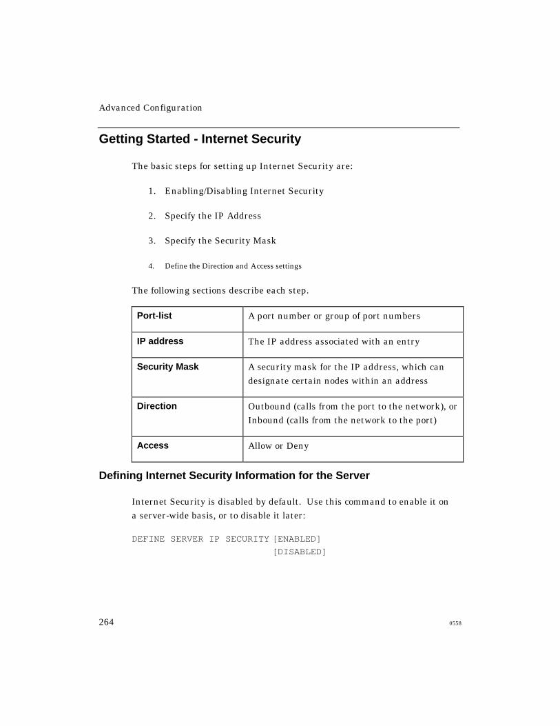
Advanced Configuration
264 0558
Getting Started - Internet Security
The basic steps for setting up Internet Security are:
1. Enabling/Disabling Internet Security
2. Specify the IP Address
3. Specify the Security Mask
4. Define the Direction and Access settings
The following sections describe each step.
Port-list A port number or group of port numbers
IP address The IP address associated with an entry
Security Mask A security mask for the IP address, which can
designate certain nodes within an address
Direction Outbound (calls from the port to the network), or
Inbound (calls from the network to the port)
Access Allow or Deny
Defining Internet Security Information for the Server
Internet Security is disabled by default. Use this command to enable it on
a server-wide basis, or to disable it later:
DEFINE SERVER IP SECURITY [ENABLED]
[DISABLED]
Advanced Configuration
0558 265
Port Security
Specify a full IP address not an abbreviation or shorthand version.
Valid IP addresses consist of four numbers, from 0 to 255, separated by
periods. For example, 192.168.19.205 and 192.168.119.0 are both valid IP
addresses. However, the abbreviation 192.168.19 is not valid.
DEFINE PORT port-list IP SECURITY security information
To define the port groups, use the following commands:
SET PORT port-list GROUPS [group-list] [DISABLED]
[ENABLED]
[ALL] [DISABLED]
[ENABLED]
To define the port’s IP Security, use the following commands:
DEFINE/SET PORT port-list IP SECURITY security info
Where the following is the security-information:
[INBOUND ALLOW] IP-address [MASK secur-
mask][ENABLED][DISABLED]
[INBOUND DENY] IP-address [MASK secur-mask]
[ENABLED][DISABLED]
[OUTBOUND ALLOW] IP-address [MASK secur-
mask][ENABLED][DISABLED]
[OUTBOUND DENY] IP-address [MASK secur-mask]
[ENABLED][DISABLED]
Advanced Configuration
266 0558
To define the port IP Security default, use the following commands:
DEFINE PORT port-list IP SECURITY DEFAULT [INBOUND] [ALLOW]
[DENY]
[OUTBOUND]
[ALLOW]
To show the access server's IP security table:
SHOW SERVER IP SECURITY
To deny all connections from ALL sources out on the ethernet from
connecting to the access server port 5:
DEFINE PORT 5 IP SECURITY DEFAULT INBOUND DENY
SET PORT 5 IP SECURITY DEFAULT INBOUND DENY
To allow host 140.179.240.14 only to connect to access server port 5 across
the LAN:
DEFINE PORT 5 IP SECURITY INBOUND ALLOW 140.179.240.14 MASK
255.255.255.255
SET PORT 5 IP SECURITY INBOUND ALLOW 140.179.240.14 MASK
255.255.255.255
At this point only host 140.179.240.14 can telnet to access server port 5,
all other host connections would be denied (this assumes remote or
dynamic access is enabled on port 5).
To deny the user on access server port 5 from connecting to any hosts on the
ethernet:
DEFINE PORT 5 IP SECURITY DEFAULT OUTBOUND DENY
SET PORT 5 IP SECURITY DEFAULT OUTBOUND DENY
Advanced Configuration
0558 267
To allow the user on access server port 5 to connect to host
140.179.240.14 only:
DEFINE PORT 5 IP SECURITY OUTBOUND ALLOW 140.179.240.14
MASK 255.255.255.255
SET PORT 5 IP SECURITY OUTBOUND ALLOW 140.179.240.14 MASK
255.255.255.255
If the mask (in examples 2 and 4 above) was set to 255.255.0.0, it would
allow connections from/to any host on the 140.179.xxx.xxx network only.
Specifying the Security Mask
A security mask specifies the portions of the IP address that the server uses
to determine where to allow or deny connections. Like an IP subnet mask,
a security mask has four segments of decimal numbers between 0 and 255,
each separated by a period.
Example
The default outbound access for server ports on a LAN is Allow. You can
create an entry in the security table that denies outbound calls from Port 4
to any node on the subnet 192.168.61.0 by using the security mask
255.255.255.0. You could then create another entry that allows outbound
calls from the port to 192.168.61.5, by using the security mask
255.255.255.255. A user at Port 4 could then reach Node 192.168.61.5 but
could not reach other nodes on the subnet because the security mask
255.255.255.255 is specific.
Advanced Configuration
268 0558
Direction and Access
The direction and access settings specify how the server restricts calls
between ports and IP addresses. You can use the following combinations of
direction and access.
NOTE: Users at privileged ports can bypass outbound IP security.
Allow Deny
Inbound Accept requests from this IPaddress at the specified ports,according to the securitymask.
Refuse requests from this IPaddress at the specified ports,according to the securitymask.
Outbound Allow requests to this IPaddress from the specifiedports, according to the securitymask.
Refuse requests to this IPaddress from the specifiedports, according to the securitymask.
Advanced Configuration
0558 269
The security table allows inbound or outbound connections between all IP
addresses and all ports by default. You can change the default in either
direction. When a user attempts to make either an inbound or an
outbound network connection, the server searches through the security
table for an entry with a matching address. If no such entry exists, the
server uses the default Access setting to determine whether to allow or
deny the connection.
You can set the default inbound and outbound connections to Deny, and
then allow connections to specific addresses. By doing so, you prevent
users from gaining access to most destinations while still providing them
with access to the resources they need. This also protects your local
network from unauthorized users.
Use these commands to change the default inbound and outbound Access:
DEFINE/SET PORT IP SECURITY DEFAULT OUTBOUND [ALLOW]
[DENY]
DEFINE/SET PORT IP SECURITY DEFAULT INBOUND [ALLOW]
[DENY]
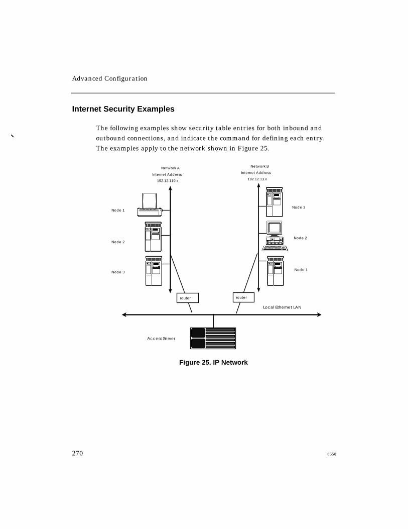
Advanced Configuration
270 0558
Internet Security Examples
The following examples show security table entries for both inbound and
outbound connections, and indicate the command for defining each entry.
The examples apply to the network shown in Figure 25.
Network A
Internet Address:
192.12.119.x
Network B
Internet Address:
192.12.13.x
Local Ethernet LAN
Access Server
Node 1
Node 2
Node 3
Node 3
Node 2
Node 1
router router
Figure 25. IP Network
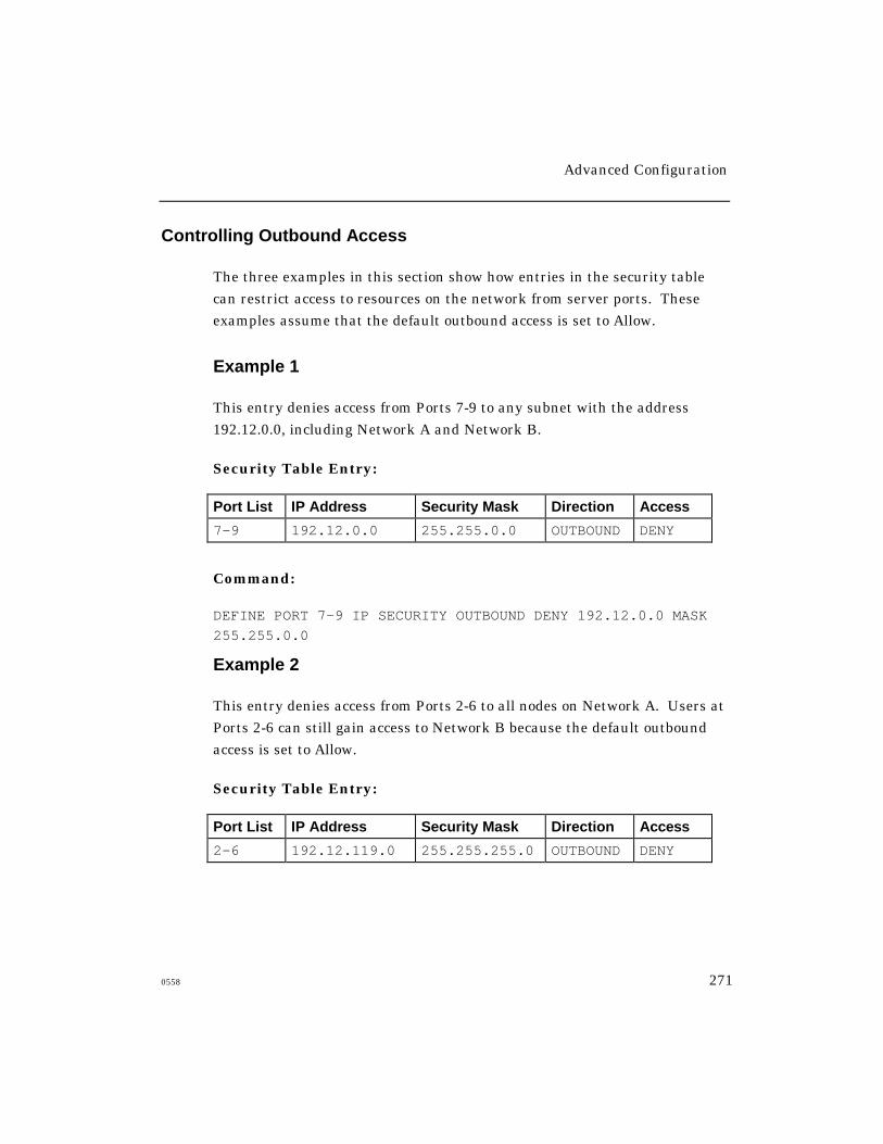
Advanced Configuration
0558 271
Controlling Outbound Access
The three examples in this section show how entries in the security table
can restrict access to resources on the network from server ports. These
examples assume that the default outbound access is set to Allow.
Example 1
This entry denies access from Ports 7-9 to any subnet with the address
192.12.0.0, including Network A and Network B.
Security Table Entry:
Port List IP Address Security Mask Direction Access
7-9 192.12.0.0 255.255.0.0 OUTBOUND DENY
Command:
DEFINE PORT 7-9 IP SECURITY OUTBOUND DENY 192.12.0.0 MASK
255.255.0.0
Example 2
This entry denies access from Ports 2-6 to all nodes on Network A. Users at
Ports 2-6 can still gain access to Network B because the default outbound
access is set to Allow.
Security Table Entry:
Port List IP Address Security Mask Direction Access
2-6 192.12.119.0 255.255.255.0 OUTBOUND DENY

Advanced Configuration
272 0558
Command:
DEFINE PORT 2-6 IP SECURITY OUTBOUND DENY 192.12.119.0 MASK
255.255.255.0
Example 3
This example assumes that the entry in Example 2 already exists in the
security table. This entry allows access from Ports 2-6 to Node 1 (the
printer on Network A) only. Users on Ports 2-6 cannot access Nodes 2 and 3
on Network A because the entry in Example 2 denies access to all nodes the
network. Because the security mask in this entry is more specific than the
entry in Example 2, however, this entry overrides the entry in Example 2.
Security Table Entry:
Port List IP Address Security Mask Direction Access
2-6 192.12.119.1 255.255.255.255 OUTBOUND ALLOW
Command:
DEFINE PORT 2-6 IP SECURITY OUTBOUND ALLOW 192.12.119.1
MASK 255.255.255.255
Controlling Inbound Access
The three examples in this section show how entries in the security table
can restrict access to server ports from nodes on the network. These
examples assume that the default inbound access is set to Allow.
Example 1
This entry disables access to Ports 2-6 from any nodes in Network A or B:
Security Table Entry:
Port List IP Address Security Mask Direction Access
2-6 192.12.0.0 255.255.0.0 INBOUND DENY
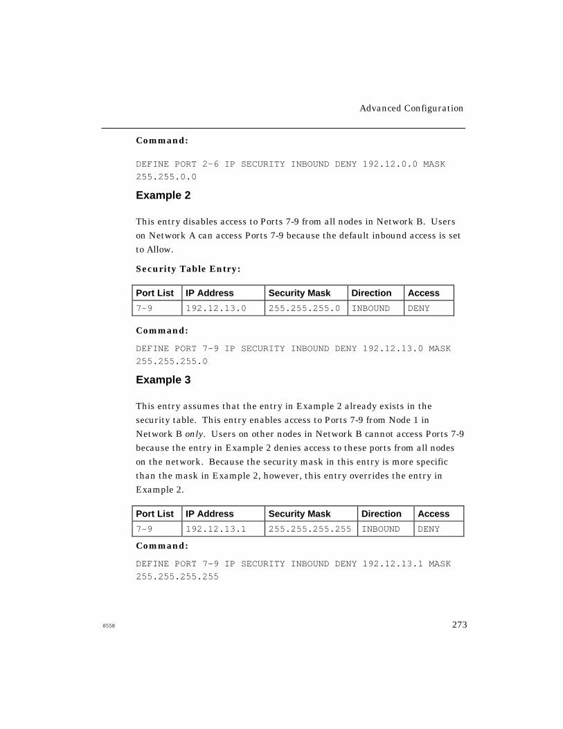
Advanced Configuration
0558 273
Command:
DEFINE PORT 2-6 IP SECURITY INBOUND DENY 192.12.0.0 MASK
255.255.0.0
Example 2
This entry disables access to Ports 7-9 from all nodes in Network B. Users
on Network A can access Ports 7-9 because the default inbound access is set
to Allow.
Security Table Entry:
Port List IP Address Security Mask Direction Access
7-9 192.12.13.0 255.255.255.0 INBOUND DENY
Command:
DEFINE PORT 7-9 IP SECURITY INBOUND DENY 192.12.13.0 MASK
255.255.255.0
Example 3
This entry assumes that the entry in Example 2 already exists in the
security table. This entry enables access to Ports 7-9 from Node 1 in
Network B only. Users on other nodes in Network B cannot access Ports 7-9
because the entry in Example 2 denies access to these ports from all nodes
on the network. Because the security mask in this entry is more specific
than the mask in Example 2, however, this entry overrides the entry in
Example 2.
Port List IP Address Security Mask Direction Access
7-9 192.12.13.1 255.255.255.255 INBOUND DENY
Command:
DEFINE PORT 7-9 IP SECURITY INBOUND DENY 192.12.13.1 MASK
255.255.255.255

Advanced Configuration
274 0558
Example 4
This entry prevents access to all destinations, because the default outbound
access is set to Deny. You would use this entry when users are to be
allowed access to a limited number of destinations.
Command:
DEFINE PORT ALL IP SECURITY OUTBOUND DEFAULT DENY
After issuing this command, you would create Allow entries for the
destinations to which users are allowed to have access.
Removing Security Table Entries
Use these commands to remove entries from the server’s IP
Security table:
CLEAR/PURGE IP SECURITY [entry]
[ALL]
An entry refers to an entry number in the List/Show Server IP
Security display.
Viewing IP Security Entries
Use these commands to view entries in the server’s IP Security tables.
Figure 26 and Figure 27 show sample displays.
LIST/SHOW/MONITOR SERVER IP SECURITY
LIST/SHOW/MONITOR PORT port-number IP SECURITY INBOUND [ALLOW]
[DENY]
LIST/SHOW/MONITOR PORT port-number IP SECURITY OUTBOUND [ALLOW]
[DENY]
LIST/SHOW/MONITOR PORT port-number IP SECURITY ip-address[ALLOW]
[DENY]
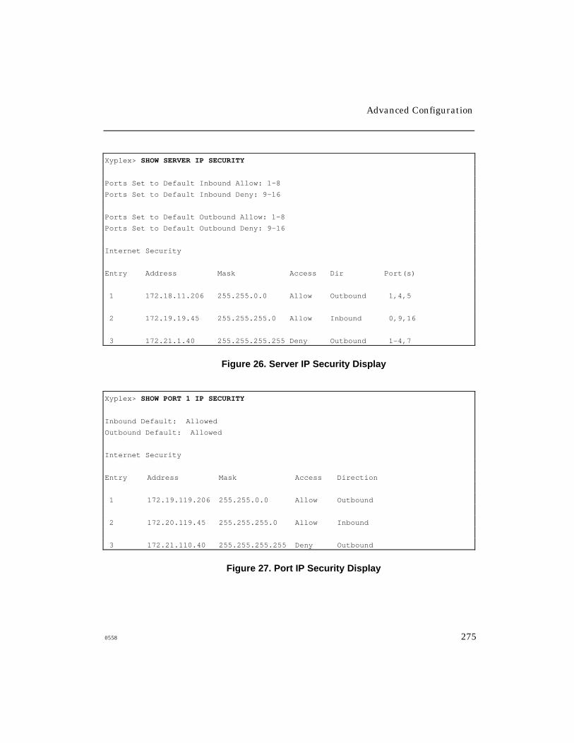
Advanced Configuration
0558 275
Xyplex> SHOW SERVER IP SECURITY
Ports Set to Default Inbound Allow: 1-8
Ports Set to Default Inbound Deny: 9-16
Ports Set to Default Outbound Allow: 1-8
Ports Set to Default Outbound Deny: 9-16
Internet Security
Entry Address Mask Access Dir Port(s)
1 172.18.11.206 255.255.0.0 Allow Outbound 1,4,5
2 172.19.19.45 255.255.255.0 Allow Inbound 0,9,16
3 172.21.1.40 255.255.255.255 Deny Outbound 1-4,7
Figure 26. Server IP Security Display
Xyplex> SHOW PORT 1 IP SECURITY
Inbound Default: Allowed
Outbound Default: Allowed
Internet Security
Entry Address Mask Access Direction
1 172.19.119.206 255.255.0.0 Allow Outbound
2 172.20.119.45 255.255.255.0 Allow Inbound
3 172.21.110.40 255.255.255.255 Deny Outbound
Figure 27. Port IP Security Display

Advanced Configuration
276 0558
Using Scripts to Enhance Network Security
Scripts are files that reside on a host system and contain server commands.
Users can run scripts from their own ports; or, network managers can
require that the server run a script when a user logs in to a port. While
scripts are not specifically designed for network security, you can use them
to enhance security on the server. Refer to the Advanced Configuration
Guide for more information about scripts. This section describes how server
scripts can improve network security through dedicated services and
through the dialback modem control feature.
Use this command to require a login script at a port:
DEFINE PORT [port-list] SCRIPT LOGIN REQUIRED
[ALL]
Dialback Modem Scripts
The Dialback feature authenticates modem users through a dialback
script. When a modem user dials in to the access server, the server does
the following:
1. Saves the username
2. Disconnects the user
3. Finds the dialback script for the user
4. Reestablishes the phone connection through the
dialback script
The user must then reenter the original username. If the user does not
enter a valid username, the server breaks the connection. The server
stops trying to make a dialback connection if the remote modem it dials
is busy or if the Port Dialback Timeout setting is exceeded.

Advanced Configuration
0558 277
Dialback scripts are similar to other scripts except that modem commands
within the script must begin the line with #modem. Dialback scripts have
the name “dialback,” and exist in the user’s script directory on the script
server. All modem commands within a script must begin with #modem,
rather than simply # .
A sample dialback script follows:
#control_script
# This is a dialback script.
#modem atdt5551978
The first line is a control command that begins all server scripts. The
second line is an optional comment line (# followed by a space designates a
line as a comment). The third line contains the phone number and the
modem keyword. (Because it is a modem command, this line begins with
#modem, rather than simply # .)
Pause Command
You might need to pause the script to give the modem time to cycle after
hanging up, or if you issue an ATDT command after an ATZ command. Use
this command to insert a pause in a script:
#pause n
The value n specifies the number of seconds to pause.
Enabling Dialback at a Port
Use this command to enable the Dialback setting at a port, or to
disable it later:
DEFINE PORT [port-list] DIALBACK [ENABLED]
[ALL]
[DISABLED]
Advanced Configuration
278 0558
Use this command to define the Dialback Timeout setting at a port.
The default timer-value is 20 seconds; you can define a value from 5 to
60 (seconds).
DEFINE PORT [port-list] DIALBACK TIMEOUT timer-value
[ALL]
Example
Xyplex>> define port 1-12 dialback timeout 30
Dial-Up Security
More and more computer networks allow dial-up access for both practical
and economic reasons. For example, dial-up access enables branch offices to
reduce connection costs by connecting to a central site only when there is
data to transfer to or from the central site. Dial-up access also allows
individual users to connect from home where leased lines are unavailable or
too costly.
With the benefit of dial-up services, however, comes the risk that
unauthorized users will try to access network resources. To prevent such
unauthorized access, called "attacks," computer networks use a variety of
security schemes. Two of the best schemes are dial-back security and time-
sensitive passwords.
Dial-Back Security
The dial-back scheme assumes that an authorized user is always dialing in
from the same place, usually home. The user dials in to an access server
and supplies his or her user name. The access server then hangs up the
connection, looks up the phone number for that user in a local database,
and dials that number back. The user must again enter the user name. If
it matches the user name entered at the first dial in, the user may then
use the network.

Advanced Configuration
0558 279
Dial-back security works well for a user dialing in from home, but it does
not work for someone on the road dialing in from a different hotel room
every night. To accommodate mobile users, there are many types of
password schemes. The most sophisticated of these are designed to prevent
unauthorized persons from capturing passwords, either by wire-tapping or
by observing a user entering the password. Time-sensitive password
schemes protect against this type of attack.
Time-Sensitive Passwords
With the time-sensitive password scheme, the user carries a security
device the size of a credit card. The device displays a periodically
changing number in an LCD display. When the user dials in and gives
his or her user name, the access server prompts for a password. The user
enters the number currently showing on the security card. To check the
password, the access server queries a local security server that is
running the same algorithm as the security card. If the passwords
match, the user may then use the network.
Xyplex remote access products, including the MAXserver 1600 Series and
the Network 3000 Model 3520 Remote Access Bridge/Router, support both
dial-back security and time-sensitive passwords. Time-sensitive password
protection is provided using Security Dynamics' SecurID system.
APD Port Authentication Command
When a new switch is enabled, users accessing through an APD
port using PPP or SLIP will be authenticated if either PAP or
CHAP is enabled on the port. Interactive users will be prompted
after the APD message displays and continue to use RADIUS or
KERBEROS authentication.
Use the following command to enable authentication and interactive
mode for an APD port:
DEFINE PORT number APD AUTHENTICATIONINTERACTIVE [ONLY] ENABLE/DISABLE
Advanced Configuration
280 0558
If you disable interactive mode, authentication will be performed
as previously.
NOTE: When you enable interactive mode also enable PAP or CHAP for
users accessing through PPP or SLIP. Otherwise, users will have
access without needing authentication.
AppleTalk Remote Access (ARAP) Notes
The following notes apply to the ARAP implementation:
• When there is no TFTP script server available on the network,
Command Control Language (CCL) scripts and dial back scripts
are unavailable.
• ARAP supports only one login password that is shared by all ARAP
users. When Kerberos or SecurID authentication is performed, a
username may be used that has an associated password and/or
passcode.
• When Kerberos or SecurID authentication is not used, the server does
not restrict access by user name. A user can login through Remote
Access using any user name as long as the user specifies the correct
server password. Specific user names are only used for locating a
telephone number for dial back.
• To prevent AppleTalk “name collisions,” do not have more than one
Remote Access Server with a given name on an AppleTalk network.
Advanced Configuration
0558 281
CCL Notes (Using Modem-Based Compression)
The following notes apply to the CCL Notes:
• ARAP connections cannot use modem-based compression.Compression must be done by the communication server. Typically,CCL scripts contain commands that prevent the modem fromnegotiating V.42 LAP-M error correction or V.42bis compression.To use modem-based V.42 LAP-M error correction or V.42biscompression for connections that are made using particularprotocols (excluding AppleTalk Remote Access Protocol (ARAP)), useCCL scripts which permit this feature to be negotiated. For moreinformation about using CCL scripts, refer to the ConfiguringAccess Serving Features guide.
• Modem-based MNP error correction is not supported on ports usingCCL scripts.
• CCLs are not supported on a port with RADIUS Authentication enabled.
Packet Rejection Message
Occasionally, a PPP LCP Packet is received that has a 0 length for the
options header. This causes the Access Server to go into an infinite loop.
During normal PPP LCP negotiations, a packet is rejected if the options
header has a length of 0, and a new packet is sought. If this packet is
accepted, the PPP negotiations proceed. The following message displays
in the Accounting Log (if Verbose priority is set to 5 or above) when a
packet is rejected:
LCP - Received Bad Structured Frame
If Kerberos or Securid is in use then the username and port number will
also display. If no security or PAP is in use, then only the port number
displays with the message.
Advanced Configuration
282 0558
Active User and Active Ports
The Active User and Port counters increments once when a user logsinto a port using RADIUS.
SNMP
The RADIUS MIB is supported. The MIB number is 4.1.33.35.
ITS NTASC RADIUS Support
Xyplex Access Servers support ITS NTASC RADIUS on Windows NT
servers. These hosts do not send back to the Xyplex, the "Service-Type and
Framed-Protocol" attributes.
As a result, it looks like a missing parameter and does not bring up the
ppp link. Since software version V6-0-1 S80, Xyplex Networks no longer
requires that the "Service-Type and Framed-Protocol" Radius attributes
be in the return packet from the Radius host. Upgrade to the latest V6-0-
1 software as required.
How the Server Obtains the Current Time
Xyplex Access Servers provide a user-settable tool for specifying where the
server obtains the current time. The tool is supported by access server units
with at least 2 MB of memory. Telnet must be enabled to support the tool.
You can require the access server to obtain the time from a specific time
server, in which case the server may only obtain the time from that server.
Alternately, you can enable it to obtain the time from a specific time server,
in which case if the server is unable to obtain the time from the specified
time server, it tries to obtain it from the first available time server,
following this order:
Advanced Configuration
0558 283
• Kerberos server through UDP, Port 37 (only if Kerberos
is enabled)
• SecurID through UDP, Port 37 (only if SecurID is enabled)
• XMOP/MOP load server obtain time from VAX load server
• UDP broadcast (through Port 37)
• Clock starts at 00:00:00
The specific time server option is disabled by default. Use these commands
to enable or require it, or to disable it later:
DEFINE/SET SERVER TIME SERVER [ENABLED ip-address]
[REQUIRED ip-address]
[DISABLED]
The ip-address that you enter with the Required keyword specifies the
only time server that the access server may use. If the access server fails
to obtain the time from this unit, it will issue time queries every 60
seconds until it is successful. The ip-address that you enter with the
Enabled keyword specifies the “preferred” time server. If the access
server fails to obtain the time from this unit within 60 seconds, it will try
an alternate server which typically means broadcasting a time query.
NOTES: Issuing the SET command instructs the access
server to issue a time query to the designated time
server immediately.
For access servers that run Kerberos or SecurID, set the Time
Server address to zero. Otherwise, if you have a Secondary
Kerberos/SecurID server defined, the access server will never
query the Secondary server.

Advanced Configuration
284 0558
Example
Xyplex>> define server time server enabled 172.19.1.101
Obtaining the Time
If the access server has a configured time server, it sends a directed UDP
query for TIME service to that unit shortly after booting. If it receives no
response, and the Server Time Server setting is Enabled (not Required), the
access server attempts to get the time from one of the other servers.
The access server attempts to resynchronize with the designated time
server on a daily basis, between midnight and 2:00 AM. Similarly, the
access server attempts to resynchronize with Kerberos or SecurID servers
daily.
Server Alternate Status Display
The “Time Received From:” field on the Server Alternate Status display
indicates the IP address of the time server where the access server obtained
the current time.
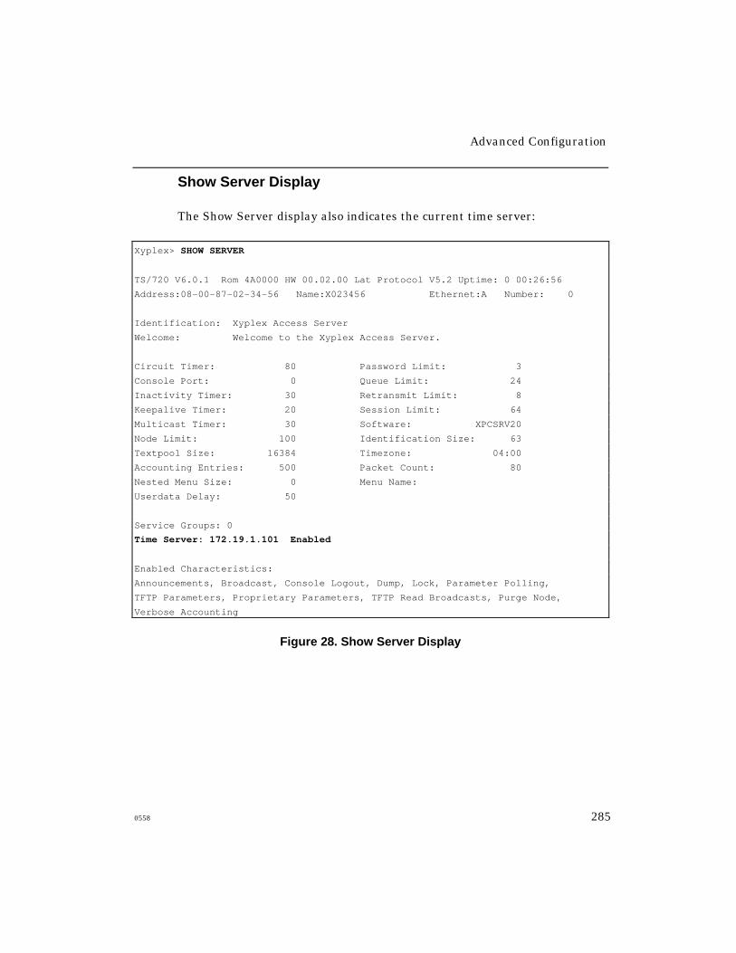
Advanced Configuration
0558 285
Show Server Display
The Show Server display also indicates the current time server:
Xyplex> SHOW SERVER
TS/720 V6.0.1 Rom 4A0000 HW 00.02.00 Lat Protocol V5.2 Uptime: 0 00:26:56
Address:08-00-87-02-34-56 Name:X023456 Ethernet:A Number: 0
Identification: Xyplex Access Server
Welcome: Welcome to the Xyplex Access Server.
Circuit Timer: 80 Password Limit: 3
Console Port: 0 Queue Limit: 24
Inactivity Timer: 30 Retransmit Limit: 8
Keepalive Timer: 20 Session Limit: 64
Multicast Timer: 30 Software: XPCSRV20
Node Limit: 100 Identification Size: 63
Textpool Size: 16384 Timezone: 04:00
Accounting Entries: 500 Packet Count: 80
Nested Menu Size: 0 Menu Name:
Userdata Delay: 50
Service Groups: 0
Time Server: 172.19.1.101 Enabled
Enabled Characteristics:
Announcements, Broadcast, Console Logout, Dump, Lock, Parameter Polling,
TFTP Parameters, Proprietary Parameters, TFTP Read Broadcasts, Purge Node,
Verbose Accounting
Figure 28. Show Server Display

Appendix A
Compatibility Issues
0558 287
LAT Compatibility
The Access Server Software is compatible with LAT Versions 5.1 and
greater. It is not compatible with LAT Version 5.0, or earlier versions. LAT
Version 5.1 is available with VMS Software Release 4.7, and later releases.
For sites running VMS Software Releases 4.4 through 4.6, Digital
Equipment Corporation provides support for LAT through a separate
layered application product, LATplus.
TCP/IP Compatibility
The access server’s TCP/IP software only supports the use of the Berkeley
Internet Name Domain Protocol (BIND) for Domain name servers, which
map user-specified domain names to IP addresses.
IP Router Compatibility
Xyplex Access Servers support directed TFTP load requests through IP
routers that support the Proxy Address Resolution Protocol (Proxy ARP).
Compatibility Issues
288 0558
Loading Parameters with TFTP Using Backup (.bck)Parameter File
If the server detects that it has received a corrupted (damaged) parameter
(.prm) file while loading parameters through TFTP, it will request a backup
(.bck) parameter file from the same parameter server. Assuming that the
backup parameter file is not corrupted, the server then loads parameters
using the backup file.
When this occurs, the Show Parameter Server display shows the IP address
of the parameter server in the “Loaded From” field and also indicates
“Status: Failed” and “Reason: Invalid” even though valid parameters
were loaded via the .bck file. If this happens, overwrite the .prm file using
the .bck file, so that both files contain the correct information. If you
change any server settings and reboot the server before overwriting the
.prm file with the .bck file, the settings you have assigned will be lost.
Appendix B
DEC Software Installation and Management Tools
0558 289
You can use standard DEC LAT tools to manage a VAX/VMS load server
or parameter server. The tools are described in the following sections.
The tools are covered in detail in the documentation supplied by DEC.
Refer to the Master Index supplied with your release of VMS software
for more information.
DECnet Network Control Program (NCP)
The NCP utility enables you to make connections to the console port of the
access server through the Maintenance Operations Protocol (MOP) Remote
Console Facility. You can use the NCP utility to define the access server as
a DECnet node and to troubleshoot network problems. The NCP utility is
supplied as part of the DECnet software.
DSVCONFIG Utility
You can use the DSVCONFIG utility in place of some of the NCP commands
when adding an access server to the network. This utility is supplied as
part of DECserver software. Note that if you do not have the DSVCONFIG
utility, you can use NCP commands instead.
DEC Software Installation and Management Tools
290 0558
Terminal Server Manager (TSM)
You can use this utility to manage the configuration of all access servers
from a central location. TSM enables you to make connections to the
console port of the access server through the Maintenance Operations
Protocol (MOP) Remote Console Facility. TSM is available from DEC.
LAT Control Program (LATCP)
You use this program to set up and control the portion of the LAT software
that runs at host computers/service nodes. LATCP is supplied with the
VMS operating system for Releases 4.7 and later. LATCP is also supplied
by DEC as part of the LATplus layered product. Typically, you use LATCP
to create a service at a host, to which users can then log on, and to start
LAT software running at the host. (You can use a DEC-supplied command
procedure, LTLOAD.COM for this.)
LATCP is also useful when setting up host-initiated connections to an
access server port. (An example of this is setting up a shared printer that is
connected to an access server port.) In this case, you use LATCP to create
an application port at a host, to map the application port to an access server
port, and to control queue operations for the application port.
VMSINSTAL Utility
You use this program to install software on a VAX/VMS load server.

INDEX
0558 291
%
% CPU used, 25
% Memory Used, 17, 25
%menu commands, 134
2
25th line
using as a status line, 116
A
Access Server Service-Selection, 221
Access to Network Resources
controlling, 209
account log
clearing the, 184
default and verbose logs, 179
accounting entries, 180
accounting feature
associated displays, 184
enabling the, 176
enabling the verbose account log, 181
memory considerations, 180
sample default account log, 181
verbose account file location, 182
Accounting Retry and Backoff Timer Process,
242
ACK bit, 37
Active User and Active Ports, 282
alternate Kerberos server
defining the, 256
alternate keymaps
associated error codes, 113
alternate keymaps, for TN3270
defining, 111
APD Port Authentication, 279
AppleTalk Remote Access (ARAP) Notes, 280
ASCIITOEBCDIC
translation table, 105
attributes
supported for RADIUS, 236, 248
Authentication, 206
authenticationFailure trap
defined, 62
authorized group, 211
available services
display field, 25
B
Backup (.bck) Parameter File, 288
Bootstrap Protocol (BOOTP), 72, 73, 191
C
Callback Modes, 231
Callback-Framed User Mode, 232
Callback-Login Parameters, 231
CARD protocol
for loading software/parameters, 190
CCL Notes (Using Modem-Based
Compression), 281
client, SNMP
defined, 65
coldStart trap
defined, 62
Index (continued)
292 0558
command script feature
how it works, 160
command buffer size
affect on memory allocation, 18
command prompt, xi
command script feature
defined, 159
defining the script name, 170
directory requirements, 167
sample scripts, 174
script file, 160
script file execution/processing, 172
script server, 160
setting up the access server, 169
TFTP security mechanisms, 168
comment lines
using in nested menu file, 139
communities, SNMP
defining the, 68
community, SNMP
defined, 65
configuration menu (initialization), 75
Configuring RADIUS Authentication on a Per-
Port Basis, 219
Configuring RADIUS on the Access Server, 216
Configuring the RADIUS Server on the Host,
216
connected nodes, 25
connected sessions, 25
console logout setting
enabling/disabling the, 72
console port, 70
contact, SNMP
defined, 69
ControlPoint, 62, 64
Conventions, xi
csportd daemon
defined, 121
D
daemons
memory used, 8
daemons, UNIX
enabling the, 121
setting up, 120
Data Encryption Standard (DES), 203
DECnet Network Control Program (NCP), 289
default account log, 179
default port numbers
for TN3270 sessions, 98
DEFINE commands, 2
Define Server Daemon command, 8
DEFINE SERVER LOADDUMP [record|ALL]
DEFAULT, 194
Define Server Nested Menu Size command, 141
Define Server Protocol command, 4
Define/Set Domain command, 80
Define/Set Parameter Server command, 77
Define/Set Server Internet Route command, 31
Define/Set Server Parameter Server Check
command, 77
accounting feature, 175
DES encryption, 206
device cancel (DevCncl)
for TN3270, 92
dialback script

Index (continued)
0558 293
defined, 160
Dial-Back Security, 278
Dial-Up Security, 278
Directed TFTP (DTFTP), 72, 75
defined, 192
discarded nodes, 25
domain name
time-to-live (TTL), 80
domain name resolution, 78
domain name server
using the server as a, 78
domain names
affect on memory allocation, 15
learned, 79
obtaining/storing, 79
DSVCONFIG utility, 289
dump transmission
through Internet protocols, 77
dynamic routing
defined, 30
E
EBCDICTOASCII
translation table, 105
encryption mechanisms, 206
error messages
indicating memory problems, 16
escape sequences, for TN3270
special values, 95
exit reset string, for TN3270
defining an, 97
F
finger user information protocol, 122
fingerd
memory used, 8
fingerd daemon
defined, 120
using the, 122
flash memory card, 188
free memory
display field, 26
fragmented, 5
free text pool
display field, 26
G
get client, SNMP
defined, 67
get next request
SNMP, 62
get request
SNMP, 62
getting started, 1
H
host route, 29
I
IBM 3270 display station functions
for TN3270 keymap, 91
identification size
affect on memory allocation, 17
import/export filters

Index (continued)
294 0558
for IPX RIP, 44
initialization record
disabling an, 194
enabling/disabling an, 187
primary/secondary/tertiary, 187
viewing an, 186
initialization records, 185
Internet domain TTL setting, 79
Internet IP Reassembly setting, 82
Internet load address, 193
Internet Load Gateway, 194
Internet routing table size, 31
Internet Security
getting started, 264
using, 208
Internet Security Information for the Server
defining, 264
IP reassembly
defined, 82
server setting, 82
IP rotary
associated commands, 54
defining an, 52
IP route
configuring an, 28
host and network routes, 29
IP Router Compatibility, 287
IP traffic filtering
associated commands, 36
defined, 33
enabling/disabling, 34
examples, 38, 39, 40
filter criteria, 34
least/most specific criteria, 35
specifying a protocol, 37
IPX RIP import and export filters, 44
IPX RIP import/export filters
defining, 45
defining RIP export filters, 45
defining RIP import filters, 46
IPX RIP import/export filtersfilters
least/most specific criteria, 45
IPX SAP import/export filters
defined, 47
defining SAP export filters, 48
defining SAP import filters, 50
filter criteria, 47
least/most specific filter, 48
IPX traffic filtering
defined, 40
enabling/disabling, 42
example, 43
filter criteria, 40
least/most specific criteria, 41
italics, xi
ITS NTASC RADIUS Support, 282
K
Kerberos
defining settings, 256
enabling the state of, 255
getting started, 255
logins without, 258
specifying version 4 or 5, 255
Kerberos Authentication, 203
enabling, 255

Index (continued)
0558 295
using, 203
Kerberos Error Messages, 257
keymap
for TN3270, 87
keymaps for TN3270
available through Xyplex, 87
modifying the, 90
L
LAT Compatibility, 287
LAT Control Program (LATCP), 290
LAT service groups
affect on memory allocation, 17
LAT services
effect on memory allocation, 14
LAT session
memory used, 12
LATCP, 290
limited vs enabled, 235
Line 25
using as a status line, 116
load protocols
configuring the, 75
Loading Parameters with TFTP, 288
loading software/parameters
through Internet protocols, 72
local printer support
via TN3270, 119
local services
affect on memory allocation, 18
display field, 25
local terminal type
for TN3270, 87
locally specified IP routes
defined, 30
location
defined, 69
location string
defined through SNMP, 69
Login Password, 196
Login Password Prompt, 196
lpd
memory used, 8
lpd demon
defined, 121
M
Maintenance Password, 197
Management Information Base (MIB)
defined, 62
MIB groups, 64
memory
identifying problems, 15
management guidelines, 11
usage for session types, 12
memory allocation, 10
settings that affect, 13
memory usage
for features and protocols, 6
memory used
display field, 17
MIB kit, 64
MIBs
how to obtain, 65
proprietary, 64
Monospace Typeface, xi

Index (continued)
296 0558
MOP protocol
for loading/dumping, 190
N
nested menu feature
creating the nested menu file, 134
debugging the menu file, 140
defined, 129
enabling/disabling on ports, 142
general guidelines, 139
how a port obtains menus, 131
how the server obtains the menu file, 131
memory allocation, 141
memory requirements, 128
naming the menu file, 142
number of levels, 129
port settings, 142
sample menu files, 144
server configuration, 140
specifying a top level menu, 143
specifying privileged menus, 143
top level menu,, 131
using comment lines, 139
using the, 128
NetWare service type, 47
network management
through SNMP, 63
Network Operations Center (NOC), 62
network route, 29
node limit
affect on memory allocation, 18
Nonprivileged, 198
NonVolitile Storage (NVS), 185
NVS protocol
for loading software/parameters, 190
O
operational database, 2
optimizing server settings, 11
Outbound Port Security, 230
P
packet buffers
affect on memory allocation, 18, 21
display field, 26
Packet Count setting, 82, 83
Packet Rejection Message, 281
parameter databases
operational and permanent, 2
parameter server check setting, 76
defined, 77
parameter server limit
affect on memory allocation, 21
parameters
retaining when upgrading software, 3
saving in permanent database, 76
parameters, for initialization
resetting to defaults, 194
PASSCODE, 206
Passwords, 195
permanent database, 2
personal identification number (PIN), 206
port 0, 70
Port Access characteristic, 209
port internet TCP window size
affect on memory allocation, 23

Index (continued)
0558 297
PORT PREFERRED SERVICE characteristic,
60
port typeahead buffer size
affect on memory allocation, 23
ports
default port numbers for Telnet, 98
default port numbers for TN3270, 98
PPP and SLIP Authentication
defining, 221
PPP CHAP Authentication
defining, 224
PPP PAP Authentication
defining, 223
Preferred service, 60
primary Kerberos server
defining the, 256
priority numbers
for messages from UNIX daemons, 183
Privilege Levels, 198
Privileged, 198
Privileged Password, 196
prompt
for privileged/mon-privileged users, xi
proprietary MIBs, 64
protocols
enabling through Define Server command, 4
protocols for loading/dumping
changing through commands, 189
enabling/disabling the, 188
Q
queue entries
display field, 25
queue limit
affect on memory allocation, 19
R
RADIUS
attributes, 236
getting started, 215
RADIUS Accounting
defining, 238
setting up, 239
RADIUS Accounting Attributes, 248
RADIUS Accounting Client Operation, 241
RADIUS Accounting for Port Logins and
Logouts
defining, 240
RADIUS Accounting Information
viewing, 245
RADIUS Accounting Logging Attempts Limits
defining, 240
RADIUS Attribute Idle-Timeout, 248
RADIUS Authentication Attributes
supported, 235
RADIUS Authentication Process
understanding the, 201
Radius Callback (Dialback), 230
RADIUS During Login
monitoring, 229
RADIUS Log Messages, 251
RADIUS Requests
canceling, 244
RADIUS Security, 214
RADIUS Server Parameters
displaying, 227

Index (continued)
298 0558
RADIUS Server-Selection, 225
RADIUS Solicitation Mode
defining, 221
reachable nodes, 25
realm
defining the, 256
Remote Console Facility, 290
resetting parameters to defaults, 194
resource errors, 26
Reverse Address Resolution Protocol (RARP),
72, 191
RLOGIN feature
associated commands, 59
configuring the, 58
considerations, 59
rotary connection
associated commands, 54
defining, 52
domain name storage, 56
on multiple servers, 55
via domain name, 55
routd daemon, 30
routed
memory used, 8
routed daemon
defined, 120
using the, 125
Routing Information Protocol (RIP), 125
dynamic routing via, 30
rwhod
memory used, 8
rwhod daemon
defined, 120
using the, 127
S
SAP types
for IPX, 49
scanner feature
Tn3270, 103
screenmap
for TN3270, 87
screenmap color, for TN3270
defining the, 96
screenmap, for TN3270
actions, 94
modifying the, 93
screenmaps for TN3270
available from Xyplex, 87
script. See command script feature
script echo setting, 170
script file
# commands, 166
creating the, 164
the # character, 166
script server
directory structure, 132, 162
setting up the, 131, 161
scroll function
for TN3270, 92
SDI encryption, 206
secret
specifying for primary Radius server, 219
Secure, 198
SecurID Authentication, 206
using, 206
Index (continued)
0558 299
SecurID Client Features, 206
security, 194
Security Dynamics Technologies, Inc, 206
Security Mask, 267
Server Change setting, 2
server identification size, 17
server node limit
affect on memory allocation, 18
server packet count
affect on memory allocation, 21
server queue limit
affect on memory allocation, 19
Server Service Groups setting
affect on memory allocation, 14
server session limit
affect on memory allocation, 19
server textpool size
affect on memory allocation, 20
Servers
defining, 261
service types
for SAP filters, 49
session limit
affect on memory allocation, 19
session types
memory used, 12
set client, SNMP
defined, 67
SET commands, 2
set request
SNMP, 62
Show Server displays
indicating memory problems, 16
Simple Network Management Protocol (SNMP),
61
SNMP, 282
traps, 62
SNMP security
configuring, 65
software load image filename
changing the, 191
solicitations
accepted/rejected, 24
static routing
defined, 30
status line information
on line 25 (TN3270), 118
Superuser, xii
Supported RADIUS Authentication Attributes,
235
SYN bit
using for traffic filtering, 33, 37
syslogd daemon
defined, 121
enabling the, 177
T
TCP resequencing
defined, 83
TCP window size
affect on memory allocation, 18
TCP/IP Compatibility, 287
Telnet Console command, 71
Telnet newline filtering setting, 90
Telnet session
memory used, 12
Index (continued)
300 0558
text pool area
defined, 10
text pool size
affect on memory allocation, 20
TFTP broadcasts
emininating the, 76
time
how the server obtains, 282
time server
address, 283
defined, 282
Time Server Enhancement, 212
TN3270
creating new device type, 88
defined, 84
defining TN3270 devices, 87
enabling extended attributes, 86
enabling the TN3270 protocol, 85
local printer support, 119
scanner feature, 103
translation tables, 85
TN3270 command
using the, 88
TN3270 device
assigning to a port, 97
TN3270 sessions
default port numbers, 98
TN3270 terminaltype
defining the, 89
TN3270 translation table
assigning to a port, 97, 108
TN3270 translation tables
defining the, 104
TN3278TYPE, 87
defining the, 89
Tn3720 session
memory used, 12
traffic filters
for IP, 33
IPX, 40
translation table, for TN3270
defining/creating a, 104
translation tables
for TN3270, 85
trap client
defining a, 65
trap community, SNMP
defining a, 68
trap, SNMP
defined, 62
Trivial File Transfer Protocol (TFTP), 72, 73,
159
typeahead buffers
affect on memory allocation, 17
defined, 22
typeahead size
affect on memory allocation, 22
typographical conventions, xi
U
UDP Port Number
defining, 240
UNIX daemons
enabling/disabling, 8
setting up, 120
upgrading memory, 12

Index (continued)
0558 301
USENGLSH language translation table
assigning to a port, 97
user prompt, xii
Using Scripts to Enhance Network Security, 276
V
verbose account log, 179
enabling the, 181
verbose priority number
defined, 182
version number
of Kerberos (4 or 5), 255
VMSINSTAL utility, 290
W
WWW site
for Xyplex, 64
X
XMOP protocol
for loading/dumping, 190
Xremote Session
memory used, 12
Xyplex WWW site, 64
Related Documents