*This paper is an updated version of a paper published in the ECOS08 proceedings. It is printed here with permission of the authors and organizers. **Corresponding Author Vol. 12 (No. 3) / 105 Int. J. of Thermodynamics Vol. 12 (No. 3), pp. 105-111, 2009 ISSN 1301-9724 www.icatweb.org/journal.htm Advanced Exergy Analysis for Chemically Reacting Systems – Application to a Simple Open Gas-Turbine System* Tatiana Morosuk 1 **, George Tsatsaronis 2 1 Institute of Marine Propulsion Plants Operation, Maritime Academy of Szczecin, Poland 2 Institute for Energy Engineering, Technische Universität Berlin, Germany E-mail: 1 [email protected]; 2 [email protected] Abstract A conventional exergy analysis has some limitations, which are significantly reduced by an advanced exergy analysis. The latter evaluates: (a) the interactions among components of the overall system (splitting the exergy destruction into endogenous and exogenous parts); and, (b) the real potential for improving a system component (splitting the exergy destruction into unavoidable and avoidable parts). The main role of an advanced exergy analysis is to provide engineers with additional information useful for improving the design and operation of energy conversion systems. This information cannot be supplied by any other approach. In previous publications, approaches were presented that were appropriate for application to closed thermodynamic cycles, without chemical reactions (e.g., refrigeration cycles). Here a general approach is discussed that could be applied to systems with chemical reactions. Application of this approach to a simple gas-turbine system reveals the potential for improvement and the interactions among the system components. Keywords: Exergy analysis, exergy destruction, avoidable exergy destruction, endogenous exergy destruction, gas- turbine system. 1. Introduction A conventional exergy analysis identifies the magnitude and the location of the real thermodynamic inefficiencies (Bejan et al., 1996). However, in revealing the causes of these inefficiencies a conventional analysis fails to identify the contributions by the other components to the exergy destruction within the component being considered. Knowledge of the interactions among components and of the potential for improving each important component is very useful in improving the overall system (Tsatsaronis, 1999a). Splitting the exergy destruction within each component of an energy conversion system into endogenous/exogenous parts ( + = EN k , D k , D E E EX k , D E ) and unavoidable/ avoidable parts ( k , D E = AV k , D UN k , D E E + ), and combining the two ap- proaches of splitting the exergy destruction ( EX , AV k , D EN , AV k , D EX , UN k , D EN , UN k , D k , D E E E E E + + + = ) enhances an exergy analysis and improves the quality of the conclusions obtained from it (Tsatsaronis and Park, 2002; Cziesla et al., 2006; Morosuk and Tsatsaronis, 2006a, 2006b, 2008; Tsatsaronis et al., 2006; Kelly, 2008; Tsatsaronis and Morosuk, 2007). These parts of exergy destruction are defined as follows. The endogenous part of exergy destruction ( EN k , D E ) is associated only with the irreversibilities occurring in the k th component when all other components operate in an ideal way and the component being considered operates with its current efficiency. The exogenous part of exergy destruction ( EX k , D E ) is caused within the k th component by the irreversibilities that occur in the remaining components. To better understand the interactions among components, the exogenous exergy destruction within the k th component should also be split. Splitting the exogenous exergy destruction within the k th component ( r , EX k , D E ) reveals the effect that the irreversibility within the r th component has on the exergy destruction within the k th component. The sum of all r , EX k , D E terms is lower than the exogenous exergy destruction within the k th component. The difference is caused by the simultaneous interactions of all (n–1) components. This difference, the mexogenous exergy destruction ( mexo k , D E ) is calculated from (Tsatsaronis and Morosuk, 2007) ∑ − ≠ = − = 1 1 n k r r r , EX k , D EX k , D mexo k , D E E E (1) where n denotes the total number of system components and r refers to all but the k th system component. Unavoidable ( UN k , D E ) is the part of exergy destruction within one system component that cannot be eliminated even if the best available technology in the near future would be applied. The avoidable ( AV k , D E ) exergy destruction is the difference between total and unavoidable exergy destruction and represents the real potential for improving the system component. By combining the two approaches for splitting exergy destruction we obtain

Welcome message from author
This document is posted to help you gain knowledge. Please leave a comment to let me know what you think about it! Share it to your friends and learn new things together.
Transcript

*This paper is an updated version of a paper published in the ECOS08 proceedings. It is printed here with permission of the authors and organizers. **Corresponding Author Vol. 12 (No. 3) / 105
Int. J. of Thermodynamics Vol. 12 (No. 3), pp. 105-111, 2009 ISSN 1301-9724 www.icatweb.org/journal.htm
Advanced Exergy Analysis for Chemically Reacting Systems – Application to a Simple Open Gas-Turbine System*
Tatiana Morosuk 1**, George Tsatsaronis 2
1 Institute of Marine Propulsion Plants Operation, Maritime Academy of Szczecin, Poland 2 Institute for Energy Engineering, Technische Universität Berlin, Germany
E-mail: [email protected]; 2 [email protected]
Abstract A conventional exergy analysis has some limitations, which are significantly reduced by an advanced exergy analysis. The latter evaluates: (a) the interactions among components of the overall system (splitting the exergy destruction into endogenous and exogenous parts); and, (b) the real potential for improving a system component (splitting the exergy destruction into unavoidable and avoidable parts). The main role of an advanced exergy analysis is to provide engineers with additional information useful for improving the design and operation of energy conversion systems. This information cannot be supplied by any other approach. In previous publications, approaches were presented that were appropriate for application to closed thermodynamic cycles, without chemical reactions (e.g., refrigeration cycles). Here a general approach is discussed that could be applied to systems with chemical reactions. Application of this approach to a simple gas-turbine system reveals the potential for improvement and the interactions among the system components. Keywords: Exergy analysis, exergy destruction, avoidable exergy destruction, endogenous exergy destruction, gas-turbine system.
1. Introduction
A conventional exergy analysis identifies the magnitude and the location of the real thermodynamic inefficiencies (Bejan et al., 1996). However, in revealing the causes of these inefficiencies a conventional analysis fails to identify the contributions by the other components to the exergy destruction within the component being considered. Knowledge of the interactions among components and of the potential for improving each important component is very useful in improving the overall system (Tsatsaronis, 1999a).
Splitting the exergy destruction within each component of an energy conversion system into endogenous/exogenous parts ( += EN
k,Dk,D EE EXk,DE ) and unavoidable/ avoidable
parts ( k,DE = AVk,D
UNk,D EE + ), and combining the two ap-
proaches of splitting the exergy destruction (EX,AV
k,DEN,AV
k,DEX,UN
k,DEN,UN
k,Dk,D EEEEE +++= ) enhances an exergy analysis and improves the quality of the conclusions obtained from it (Tsatsaronis and Park, 2002; Cziesla et al., 2006; Morosuk and Tsatsaronis, 2006a, 2006b, 2008; Tsatsaronis et al., 2006; Kelly, 2008; Tsatsaronis and Morosuk, 2007). These parts of exergy destruction are defined as follows.
The endogenous part of exergy destruction ( ENk,DE ) is
associated only with the irreversibilities occurring in the k th component when all other components operate in an ideal way and the component being considered operates with its current efficiency.
The exogenous part of exergy destruction ( EXk,DE ) is
caused within the k th component by the irreversibilities that occur in the remaining components.
To better understand the interactions among components, the exogenous exergy destruction within the k th component should also be split.
Splitting the exogenous exergy destruction within the k th component ( r,EX
k,DE ) reveals the effect that the irreversibility within the r th component has on the exergy destruction within the k th component. The sum of all
r,EXk,DE terms is lower than the exogenous exergy
destruction within the k th component. The difference is caused by the simultaneous interactions of all (n–1) components. This difference, the mexogenous exergy destruction ( mexo
k,DE ) is calculated from (Tsatsaronis and Morosuk, 2007)
∑−
≠=
−=1
1
n
krr
r,EXk,D
EXk,D
mexok,D EEE (1)
where n denotes the total number of system components and r refers to all but the k th system component.
Unavoidable ( UNk,DE ) is the part of exergy destruction
within one system component that cannot be eliminated even if the best available technology in the near future would be applied.
The avoidable ( AVk,DE ) exergy destruction is the
difference between total and unavoidable exergy destruction and represents the real potential for improving the system component.
By combining the two approaches for splitting exergy destruction we obtain
106
•
•
desof avo
desMo 2. T
des(TsCzexo200Moendcherepconcalthisal.,cancomdescom(Met aprea cprewitinv
2.1
sysexe
6 / Vol. 12 (No
the unavo
unavoidabldestruction
the avoid
avoidable destructioncomponentsubsystem structure), r
The splittingstruction (Eq.the unavoida
oidable exogeFigure 1 sum
struction withorosuk, 2007)
The approachPast publica
struction intsatsaronis, 19iesla et al., ogenous parts08; Tsatsaroniorosuk, 2007;dogenous exeemical reactiopresents a prnditions can blled “engineers problem (Ts, 2009). Heren be applied mplex energscribed in thmpared with t
Morosuk and Tal., 2006; Tsaesented here oconventional esent approacth the size anvestigation.
1. Real operatFirst a detai
stem being coergy destructi
Figure 1: O
o. 3)
oidable endo
le exogenousn, and dable endog
exogenous n that can bet being con
(single crespectively.
g of the ex(1)) should a
able exogenouenous parts of mmarizes all ohin the k th .
h for splittingations considto unavoida
999a, 1999b; 2006) as w
s (Morosuk anis et al., 2006; Kelly et alergy destruction takes placeroblem becau
be defined forring approachsatsaronis et ae a new gener
easier than gy conversiohe following the approach
Tsatsaronis, 20atsaronis and Movercomes theexergy analy
ch could havend complexity
ting conditioniled exergy aonsidered opeon in each sy
Options for sp
ogenous ( UDE
s ( EX,UNk,DE )
genous ( AVk,DE
( EX,AVk,DE ) p
e reduced bynsidered, or components
ogenous partalso be appliedus, and, more exergy destru
options for splcomponent (
g exergy destered the spliable and a
Tsatsaronis well as into nd Tsatsaroni
6; Kelly, 2008l., 2009). Thion in a com
e in the remainuse no idear the reaction
h” was develoal., 2006; Kellral approach the engineer
on systems. has some slused for refri
006a, 2006b, 2Morosuk, 200e most importaysis (Tsatsarone some limitay of the over
ns analysis is coerating at realystem compon
plitting the exe
EN,UNk,D ) and
parts of exe
EN,Vk ) and
parts of exey improving
the remainor subsyst
t of the exed to the splittimportantly,
uction. litting the exe(Tsatsaronis
truction itting of exeavoidable pand Park, 20endogenous
is, 2006a, 200; Tsatsaronis
he calculationmponent whenning compone
al (“theoreticprocess. The ped to overcoly, 2008; Kellyis presented t
ring approachThe appro
light differenigeration syste2008; Tsatsaro7). The approant limitationnis, 1999a). Tations associaall system un
onducted for l conditions. Tnent is calcula
ergy destructi
the
ergy
the
ergy the
ning tem
ergy ting the
ergy and
ergy parts 002; and
06b, and
n of n a ents al”) so-
ome y at that
h to oach nces ems onis oach s of The ated nder
the The ated
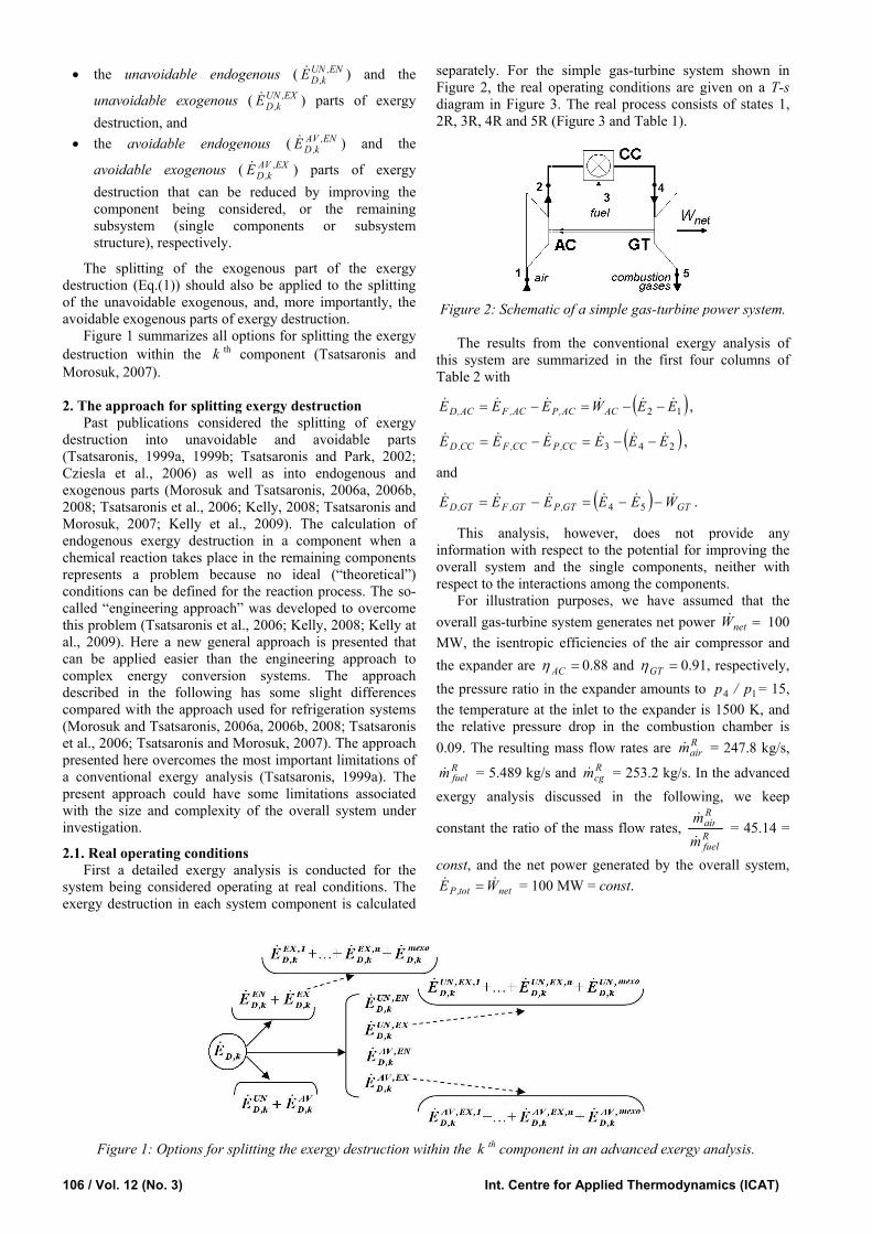
separaFigurediagra2R, 3R
Figur
Ththis syTable
E AC,D
E CC,D
and
GT,DE
Thinformoveralrespec
ForoveralMW, tthe expthe prethe temthe re0.09. T
Rfuelm
exergy
consta
const,
tot,PE
ion within the
Int. Centre
ately. For thee 2, the real om in Figure 3
R, 4R and 5R
re 2: Schemati
he results fromystem are sum2 with
EE AC,FC −=
EE CC,FC −=
GT,FT EE −=
his analysis, mation with re
l system andct to the interar illustration l gas-turbine the isentropicpander are Aηessure ratio inmperature at tlative pressurThe resulting
= 5.489 kg/s y analysis d
ant the ratio o
and the net p
netW= = 100
k th compone
for Applied T
e simple gas-operating con3. The real pr(Figure 3 and
ic of a simple
m the convenmmarized in
WACAC,P −=
(3 EEE CC,P −=
(GT,P EE −= 4
however, espect to the pd the single ctions among purposes, w
system generac efficiencies
=AC 0.88 andn the expandethe inlet to thre drop in thmass flow ra
and Rcgm = 2
discussed in
f the mass flo
power genera0 MW = const
ent in an advan
Thermodynam
-turbine systenditions are girocess consistTable 1).
gas-turbine p
ntional exergythe first four
( )12 EE − ,
)24 EE − ,
) GTWE −5 .
does not ppotential for icomponents, the componen
we have assumates net poweof the air com
d =GTη 0.91,r amounts to
he expander ishe combustionates are R
airm
253.2 kg/s. In the followin
ow rates, Rfu
Ra
mm
ated by the ovt.
nced exergy a
mics (ICAT)
em shown iniven on a T-sts of states 1,
power system.
y analysis ofr columns of
provide anyimproving the
neither withnts. med that the
er =netW 100mpressor and, respectively,
14 p/p = 15,s 1500 K, andn chamber is= 247.8 kg/s,
the advancedng, we keep
uel
Rir = 45.14 =
verall system,
analysis.
n s ,
f f
y e h
e 0 d , ,
d s ,
d p
=
,

Int. J. of Thermodynamics (IJoT) Vol. 12 (No. 3) / 107
Figure 3: Real, theoretical, unavoidable and hybrid processes for simple gas-turbine power system showed in Figure 2: air , fuel, combustion gases.
Table 1. Thermodynamic data for the real (R), theoretical (T), unavoidable (U) and hybrid processes (H) of the simple gas-turbine power system.
Stre
am
T
[K] p
[bar
]
ePH
[MJ/
kg]
eCH
[MJ/
kg]
e [M
J/kg
]
1 298 1.013 0 0 0 2T 636 15.2 0.350 0 0.350 2H2 652 16.71 0.368 0 0.368 2U 662 15.35 0.366 0 0.366 2H1 680 15.2 0.376 0 0.376 2R 698 16.71 0.396 0 0.396 3T 298 15.2 0.418 51.38 51.8 3U 298 15.5 0.421 51.38 51.8 3R 298 18 0.445 51.38 51.83 4U 2100 15.2 1.878 0.020 1.898 4R= 4T
1500 15.2 1.113 0.005 1.119
5U 943 1.025 0.629 0.020 0.649 5R 859 1.025 0.281 0.005 0.286 5T 1216 1.013 0.228 0.005 0.233
For calculating the values of unavoidable
irreversibilities within each system component, we assumed conditions that cannot be realized in the next decade:
=UNACη 0.93, =UN
GTη 0.96, an adiabatic combustion process with T4=2100 K and a relative pressure drop in the combustion chamber of 0.01.
The composition of the combustion gases for the process with only unavoidable irreversibilities is different than the composition of combustion gases for the real process. Therefore, for showing the process with unavoidable irreversibilities we need four more isobaric lines p2,U, p3,U, p4,U and p5,U (Figure 3).
For calculating the value of the unavoidable exergy destruction within the k th component, the following procedure is used (detailed description is given in Tsatsaronis and Park, 2002; Cziesla et al., 2006).
UN
k,P
k,Dk,D
UNk,D E
EEE ⎟
⎟⎠
⎞⎜⎜⎝
⎛= (2)
where the value UN
k,P
k,D
EE
⎟⎟⎠
⎞⎜⎜⎝
⎛ should be calculated using the
process with unavoidable irreversibilities.
The values UN
k,P
k,D
EE
⎟⎟⎠
⎞⎜⎜⎝
⎛ are given in Table 2 and the
values UNk,DE and AV
k,DE are presented in Table 3. The exergetic efficiency of the overall gas-turbine power system operating at the given pressure ratio and at conditions that are associated with unavoidable exergy destruction is
=UNtotε 40.4%. Thus the potential for improving the overall
efficiency of such a system (without an air preheater) and at the given pressure ratio of about 15 is approximately 5 percentage points.
2.2. Theoretical operating conditions
For splitting the exergy destruction into endogenous and exogenous parts, and for further splitting the exogenous part of the exergy destruction, we need to describe the theoretical operation conditions for each component of the gas-turbine power system.
The theoretical operational conditions for the air compressor and the gas turbine are similar: 0=T
AC,DE
( 1=TACε or 1=T
ACη ) and 0=TGT,DE ( 1=T
GTε or 1=TGTη ).
The following assumptions are made for the theoretical combustion chamber:
• The thermodynamic properties of the combustion gas and the composition of it remain the same as in the real operating conditions (state 4T = state 4R),
• The pressure drop in the combustion chamber is zero, p2 = p4,
• State 4T(=4R) should be the result of the chemical reaction between the streams at states 2T and 3T,
• The excess air at theoretical conditions is equal to the
excess air in the real process: Rfuel
Rair
Tfuel
Tair
mm
mm
= , and

108
•
Figsys
anyful
(Fi
com•
E2
or
Te2
•
nW
wit
con
and
befandbal
com
(EX
genmacon
can
DEtheandKe
8 / Vol. 12 (No
With respectsystem is splcombination chamber whi(Figure 4).
gure 4: Sub-stem.
In general ay chemical refilled.
The theoretigure 3).
The conditimbination of t Since we cabalances simchamber, we
TT EE 432 =+
TTairT em +⋅ 3
In addition, wTcg
TGTnet mw ⋅=
th netW = 100For the gas
nditions we h
d Tcgm = 160.3
It is apparentfore, the overd, therefore, lance. If the ov
mponents, weA throttling
X) with EXη =For a heat
nerator, for achine (Morondition E k,D =
We concludennot always b
tot,D = 0 andeoretical operad Tsatsaroniselly, 2008) wit
o. 3)
t to mass ballit into two suof the air com
ile sub-system
-systems of
a new subsysteactor in whic
tical process
ion 0=TCC,DE
the following annot fulfill t
multaneously f fulfill only th
T4 ,
TTfuel em ⋅=⋅ 4
we fulfill the fTair
TAC
Tg mw ⋅−
0 MW. s-turbine syst
have: Tairm = 1
3 kg/s.
t that Tair mm +
rall system iwe do not
erall system would use thvalve should
=1 (Morosuk at exchanger example for
osuk and Tsmin= is poss
e that the ovebe described ad tot,Dε = 1)ational conditi, 2006a, 200th minE T
k,D =
lances, the gaub-systems: sumpressor with
m II consists on
a simple ga
tem should bech the mass b
is 1 – 2T –
0 can be achtwo equationsthe mass, enefor the theorehe exergy bala
Tcgm⋅ ,
following bala
tem at theor119.8 kg/s, m
Tcg
Tfuel mm ≠ . A
s split into tneed to con
m would cone following pr
d be replaced and Tsatsaron
(including an absorpti
satsaronis, 20ible, with pTΔ
erall energy coat ideal opera). When this ions should b
06b; Tsatsaronn and T
k maε =
as-turbine powub-system I is h the combustnly of the turb
as-turbine po
e introduced aalance cannot
4T (2T+3T) –
hieved througs (3) and (5).ergy and exe
etical combustance:
ance
retical operatTfuelm = 2.654 k
As we mentiotwo sub-systensider this m
ntain additiorocedures: by an expan
nis, 2006a, 200an absorber ion refrigerat008)), only
pinchT =0. onversion sysating condition
is not possie used (Moronis et al., 20ax .
wer the
tion bine
wer
after t be
– 5T
gh a
ergy tion
(3)
(4)
(5)
ting kg/s
oned ems, mass
onal
nder 08).
or tion the
tem ns (ible, osuk 006;
2.3. HFor
endogeendogeproceswith itall oththis cbeing unavoiby-stepsystem(the ueach c
Fordestrucprocesproceswhile operat
• Air pro• Co pro• Ga pro
Thshouldprocescomprdescribwith oexergy
2E + ε
where chamb
Th
Tablecalculaadvanc
Toexergythe fol
E,UNk,DE
ThE,AV
k,DE 2.4. H
Fordestruchybridevery to be i
Int. Centre
Hybrid procesr splitting enous/exogenenous/unavoidsses in which ts real efficien
her componentase, the exer
considered idable endogep introducing
m component unavoidable eomponent. r calculating ction within ssses - 1 shoulss only one cothe remaininging conditions
r compressor ocess 1 –2H1 –ombustion chaocess 1 –2H2 –as turbine ( E
DEocess 1 –2T – 4
e mass flow d be calculatedss with irreressor or onlbed by Eqs. only irreversiby balance in th
43 EECC =ε
CCε is the ber at real operhe values EN
k,DE
3. The valuated because ced exergy an calculate th
y destruction llowing equati
P
DENk,P
EN
EE
E ⎜⎜⎝
⎛=
he results obtaEX are given in
Hybrid procesr splitting tction within
d processes –one of these prreversible:
for Applied T
ses - 1 the exergy
nous parts (odable exogenonly one comncy (or its unats operate in argy destructio
represents enous) exergyg irreversibilienables us to
endogenous)
the endogeystem compold be analyzedomponent is ag componentss:
( ENAC,DE ) –
4T (3T +2H1) –amber ( EN
CC,DE4T (3R +2H2) –
ENGT,D ) –
4T (3T +2T) – 5
rates of air, fd for each hybeversibilities ly in the ga(3)-(5) is usebilities in thehis component
exergetic effirating conditio
Nk as well as th
ues ENk,PE (T
they are neednalysis. e unavoidablwithin a syst
ion UN
k,P
k,D⎟⎟⎠
⎞
ined for UNk,DE
n Table 3.
ses - 2 the exogenoeach system 2 should be
processes, two
Thermodynam
y destructionor into the
nous parts) wmponent is real
avoidable effian ideal/theoron within th
the endogy destructionities successivo calculate theexergy destru
nous part ofnents, the folld (Figure 3). assumed to bes operate at th
– 5T , ) –
– 5T, and
5R.
fuel and combbrid process. F
either only as turbine, thed. For the hy combustion t becomes
ficiency of theons.
he values EXk,DE
Table 2) shoded for the ne
e endogenoutem compone
EN,Nk , EX,UN
k,DE ,
ous part of component, tintroduced (
o components
mics (ICAT)
n into theunavoidable
we use hybridl, i.e. operatesciency) whileetical way. Ine componentgenous (the
n. Thus, step-vely in eache endogenousuction within
f the exergylowing hybridIn each such
e irreversible,he theoretical
bustion gasesFor the hybrid
in the airhe procedureybrid processchamber, the
(6)
e combustion
Xk are given in
ould also bext step of the
s part of theent, we apply
(7)
, EN,AVk,DE and
the exergythe following(Figure 3). Ins are assumed
e e d s e n t e -h s n
y d h , l
s d r e s e
)
n
n
e e
e y
)
d
y g n d

Int. J. of Thermodynamics (IJoT) Vol. 12 (No. 3) / 109
• Air compressor and combustion chamber for calculating the values CC,EX
AC,DE and AC,EXCC,DE – process 1 –2R – 4R (3R
+2R) – 5T, • Air compressor and gas turbine for calculating the
values GT,EXAC,DE and AC,EX
GT,DE – process 1 –2H1 – 4T (3T+2H1) – 5R, and
• Combustion chamber and gas turbine for calculating the values GT,EX
CC,DE and CC,EXGT,DE – process 1 –2H2 – 4R (3R
+2H2) – 5R.
The value of r,EXk,DE (Table 3) is calculated by
ENk,D
r,kk,D
r,EXk,D EEE −= (8)
The values r,kk,DE are given in Table 2.
For splitting the unavoidable exogenous part of the exergy destruction within a system component, we need a procedure similar to the one described by Eqs. (8) and (9)
EN,UNk,D
r,k,UNk,D
r,EX,UNk,D EEE −= (9)
with
UN
k,P
k,Dr,kk,P
r,k,UNk,D E
EEE ⎟
⎟⎠
⎞⎜⎜⎝
⎛= (10)
The values of r,kk,PE are given in Table 2 and the results
are presented in Table 3. 3. Discussion and conclusion
When we evaluate the thermodynamic performance of a system component, it is very helpful to know (a) what part of the exergy destruction is caused by which other component, and (b) what part of the exergy destruction within the component being considered could be avoided. This information is obtained with the aid of theoretical, hybrid and unavoidable processes that are considered together with the real process.
This paper demonstrates how to define all these processes and how to split the exergy destruction within a system component into its parts unavoidable/avoidable and endogenous/ exogenous as well as unavoidable endogenous, unavoidable exogenous, avoidable endogenous and avoidable exogenous. The system evaluation is based on the last two parts of exergy destruction.
Compared with the conventional exergy analysis of a simple gas-turbine power system we obtain the following additional information with the aid of an advanced exergy analysis:
1. The potential for improving the efficiency of the overall system is approximately 5 percentage points because over 70% of the exergy destruction in the overall system is unavoidable.
2. Only one fourth of the exergy destruction in the combustion chamber is avoidable. For the combustion chamber, the avoidable endogenous exergy destruction (to be reduced, for example, by increasing the temperature T4) is four times higher than the avoidable exogenous exergy destruction (to be reduced through improvements in the air compressor and the expander).
3. Over 50% of the exergy destruction in the air compressor is exogenous whereas this percentage is
approximately 27% for the expander and 22% for the combustion chamber.
4. An improvement in the expander would affect not only the endogenous avoidable exergy destruction of this component but also the exogenous avoidable exergy destruction within the combustion chamber. Nomenclature
E exergy rate [W] e specific exergy [J/kg] m mass flow rate [kg/s] p pressure [bar]
Q heat rate [W]
gens specific entropy generation [J/kg·K] T temperature [K] W power [W]
Greek symbols
Δ difference ε exergetic efficiency η isentropic efficiency
Abbreviations
AC air compressor CC combustion chamber GT gas turbine (expander)
Subscripts
D destruction F fuel H point of a hybrid process k k th component P product R point of a real process U point of a process with unavoidable exergy destruction T point of a theoretical process tot overall system 0 thermodynamic environment
Superscripts
AV avoidable ch chemical exergy EN endogenous EX exogenous k k th component mexo mexogenous n number of components ph physical exergy r r th component (different from the k th component being considered) R real operation conditions T theoretical operation conditions UN unavoidable

110 / Vol. 12 (No. 3) Int. Centre for Applied Thermodynamics (ICAT)
Ta
ble
2: D
ata
obta
ined
from
the
conv
entio
nal e
xerg
y an
alys
is a
nd so
me
data
for t
he a
dvan
ced
exer
gy a
naly
sis.
Tabl
e 3:
Con
vent
iona
l and
adv
ance
d ex
ergy
ana
lyse
s for
the
sim
ple
gas-
turb
ine
pow
er sy
stem
.
Int. J. of Thermodynamics (IJoT) Vol. 12 (No. 3) / 111
References Bejan, A., Tsatsaronis, G. and Moran, M., 1996, Thermal design and optimization. New York: Wiley. Cziesla, F., Tsatsaronis, G. and Gao, Z., 2006, “Avoidable thermodynamic inefficiencies and costs in an externally fired combined cycle power plant”, Energy Int. J., Vol. 31, No.10–11, pp. 1472–1489. Kelly, S., 2008, “Energy systems improvement based on endogenous and exogenous exergy destruction”, Ph.D. dissertation, Technische Universität Berlin, Germany. Kelly, S, Tsatsaronis, G. and Morosuk, T., 2009, “Advanced exergetic analysis: Approaches for splitting the exergy destruction into endogenous and exogenous parts”, Energy Int. J., Vol. 34, pp. 384-391. Morosuk, T. and Tsatsaronis, G., 2006a, “The “Cycle Method” used in the exergy analysis of refrigeration machines: from education to research”, Proceedings of the 19th international conference on efficiency, cost, optimization, simulation and environmental impact of energy systems, Frangopoulos, C. et al., ed., Aghia Pelagia, Crete, Greece, Vol. 1, pp. 157–63. Morosuk, T. and Tsatsaronis, G., 2006b, “Splitting the exergy destruction into endogenous and exogenous parts – application to refrigeration machines”, Proceedings of the 19th international conference on efficiency, cost, optimization, simulation and environmental impact of energy systems, Frangopoulos, C. et al., ed., Aghia Pelagia, Crete, Greece, Vol. 1, pp. 165–172.
Morosuk, T. and Tsatsaronis, G., 2008, “New approach to the exergy analysis of absorption refrigeration machines”, Energy Int. J., Vol. 33, pp. 890-907. Tsatsaronis, G., 1999a, “Strengths and limitations of exergy analysis”, Thermodynamic optimization of complex energy systems, Bejan, A. and Mamut, E., eds., Dordrecht: Kluwer Academic Publishers, pp. 93–100. Tsatsaronis, G., 1999b, “Design optimization using exergoeconomics”, Thermodynamic optimization of complex energy systems, Bejan, A. and Mamut, E., eds., Dordrecht: Kluwer Academic Publishers, pp.101–117. Tsatsaronis, G., Kelly, S. and Morosuk, T., 2006, “Endogenous and exogenous exergy destruction in thermal systems”, Proceedings of the ASME International Mechanical Engineering Congress and Exposition, Chicago, USA, CD-ROM, file 2006-13675. Tsatsaronis, G. and Morosuk, T., 2007, “Advanced exergoeconomic evaluation and its application to compression refrigeration machines”, Proceedings of the ASME International Mechanical Engineering Congress and Exposition, Seattle, USA, CD-ROM, file 2007-41202. Tsatsaronis, G. and Park, M.H., 2002, “On avoidable and unavoidable exergy destructions and investment costs in thermal systems”, Energy Conversion and Management, Vol. 43, pp.1259–1270.
Related Documents