1 VALIDATION GUIDE

Welcome message from author
This document is posted to help you gain knowledge. Please leave a comment to let me know what you think about it! Share it to your friends and learn new things together.
Transcript

1
VALIDATION GUIDE

2
Advance Design
Validation Guide Volume I
Version: 2022
Tests passed on: 31 May 2021
Number of tests: 952

ADVANCE VALIDATION GUIDE
3
INTRODUCTION
The Advance Design Validation Guide 2022 outlines a vast set of practical test cases showing the behavior of Advance Design 2022 in various areas and various conditions. The tests cover a wide field of expertise:
• Modeling
• Combinations Management according to Eurocode 0, CR 0-2012, CISC and AISC
• Climatic Load Generation according to Eurocode 1, CR1-1-3/2012, CR1-1-4/2012,
NTC 2008, NV2009, NBC 2015 and ASCE 7-10
• Meshing
• Finite Element Calculation
• Reinforced Concrete Design according to Eurocode 2, NTC 2008 and CSA
• Steel Member Design according to Eurocode 3, NTC 2008, AISC and CSA
• Timber Member Design according to Eurocode 5
• Seismic Analysis according to Eurocode 8, PS92, RPA99/2003, RPS 2011
• Pushover Analysis according to Eurocode 8, FEMA 356, ATC 40
• Report generation
• Import / Export procedures
• User Interface Behavior
Such tests are generally made of a reference (independent of the specific software version tested), a transformation (a calculation or a data-processing scenario), a result (given by the specific software version tested) and a difference, usually measured in percentage as a drift from a specific set of reference values. Depending on the cases, the used reference can be a theoretical calculation performed manually, a sample taken from the technical literature, or the result of a previous version considered as accurate by experience.
In the field of structural analysis and design, software users must always keep in mind that the results depend, to a great extent, on the modeling (especially when dealing with finite elements) and on the settings of the numerous assumptions and options available in the software. A software package cannot entirely replace engineers’ experience and analysis. Despite all the efforts we have made in terms of quality management, we cannot guaranty the correct behavior and the validity of the results issued by Advance Design in any given situation.
This complex validation process is carried out along with and in addition to manual testing and beta testing, to attain the "operational version" status. Its outcome is the present guide, which contains a thorough description of the automatic tests, highlighting both the theoretical background and the results that our validation experts have obtained by using the current software release. We hope that this guide will highly contribute to the knowledge and the confidence you keep placing in Advance Design.
Ionel DRAGU
Graitec Innovation CTO

ADVANCE VALIDATION GUIDE
4
– 1 FINITE ELEMENT METHOD ............................................................................................ 12
1.1 Cantilever rectangular plate (01-0001SSLSB_FEM) ................................................................................ 13
1.2 System of two bars with three hinges (01-0002SSLLB_FEM) ................................................................ 15
1.3 Circular plate under uniform load (01-0003SSLSB_FEM) ....................................................................... 18
1.4 Slender beam with variable section (fixed-free) (01-0004SDLLB_FEM) ................................................ 20
1.5 Tied (sub-tensioned) beam (01-0005SSLLB_FEM) .................................................................................. 23
1.6 Thin circular ring fixed in two points (01-0006SDLLB_FEM) .................................................................. 27
1.7 Thin lozenge-shaped plate fixed on one side (alpha = 0 °) (01-0007SDLSB_FEM) ............................... 30
1.8 Thin lozenge-shaped plate fixed on one side (alpha = 15 °) (01-0008SDLSB_FEM) ............................. 32
1.9 Thin lozenge-shaped plate fixed on one side (alpha = 30 °) (01-0009SDLSB_FEM) ............................. 34
1.10 Thin lozenge-shaped plate fixed on one side (alpha = 45 °) (01-0010SDLSB_FEM) ............................ 36
1.11 Vibration mode of a thin piping elbow in plane (case 1) (01-0011SDLLB_FEM) ................................. 38
1.12 Vibration mode of a thin piping elbow in plane (case 2) (01-0012SDLLB_FEM) ................................. 40
1.13 Vibration mode of a thin piping elbow in plane (case 3) (01-0013SDLLB_FEM) ................................. 42
1.14 Thin circular ring hanged on an elastic element (01-0014SDLLB_FEM) .............................................. 44
1.15 Double fixed beam with a spring at mid span (01-0015SSLLB_FEM)................................................... 47
1.16 Double fixed beam (01-0016SDLLB_FEM) .............................................................................................. 50
1.17 Short beam on simple supports (on the neutral axis) (01-0017SDLLB_FEM) ..................................... 54
1.18 Short beam on simple supports (eccentric) (01-0018SDLLB_FEM) ..................................................... 57
1.19 Thin square plate fixed on one side (01-0019SDLSB_FEM) .................................................................. 61
1.20 Rectangular thin plate simply supported on its perimeter (01-0020SDLSB_FEM) .............................. 64
1.21 Cantilever beam in Eulerian buckling (01-0021SFLLB_FEM) ................................................................ 67
1.22 Annular thin plate fixed on a hub (repetitive circular structure) (01-0022SDLSB_FEM) ..................... 69
1.23 Bending effects of a symmetrical portal frame (01-0023SDLLB_FEM) ................................................ 71
1.24 Slender beam on two fixed supports (01-0024SSLLB_FEM) ................................................................. 74
1.25 Slender beam on three supports (01-0025SSLLB_FEM) ....................................................................... 78
1.26 Bimetallic: Fixed beams connected to a stiff element (01-0026SSLLB_FEM) ..................................... 81
1.27 Fixed thin arc in planar bending (01-0027SSLLB_FEM) ........................................................................ 84
1.28 Fixed thin arc in out of plane bending (01-0028SSLLB_FEM) ............................................................... 86
1.29 Double hinged thin arc in planar bending (01-0029SSLLB_FEM) ......................................................... 88
1.30 Portal frame with lateral connections (01-0030SSLLB_FEM) ................................................................ 90
1.31 Truss with hinged bars under a punctual load (01-0031SSLLB_FEM) ................................................. 93
1.32 Beam on elastic soil, free ends (01-0032SSLLB_FEM) .......................................................................... 95
1.33 EDF Pylon (01-0033SFLLA_FEM) ............................................................................................................ 98
1.34 Beam on elastic soil, hinged ends (01-0034SSLLB_FEM) ................................................................... 102
1.35 Simply supported square plate (01-0036SSLSB_FEM) ........................................................................ 105
1.36 Caisson beam in torsion (01-0037SSLSB_FEM) .................................................................................. 107

ADVANCE VALIDATION GUIDE
5
1.37 Thin cylinder under a uniform radial pressure (01-0038SSLSB_FEM) ............................................... 109
1.38 Square plate under planar stresses (01-0039SSLSB_FEM) ................................................................. 111
1.39 Stiffen membrane (01-0040SSLSB_FEM) .............................................................................................. 114
1.40 Beam on two supports considering the shear force (01-0041SSLLB_FEM) ...................................... 117
1.41 Thin cylinder under a uniform axial load (01-0042SSLSB_FEM) ......................................................... 119
1.42 Thin cylinder under a hydrostatic pressure (01-0043SSLSB_FEM) .................................................... 122
1.43 Thin cylinder under its self weight (01-0044SSLSB_MEF)................................................................... 125
1.44 Torus with uniform internal pressure (01-0045SSLSB_FEM) .............................................................. 127
1.45 Spherical shell under internal pressure (01-0046SSLSB_FEM) .......................................................... 129
1.46 Pinch cylindrical shell (01-0048SSLSB_FEM) ....................................................................................... 132
1.47 Spherical shell with holes (01-0049SSLSB_FEM) ................................................................................. 134
1.48 Spherical dome under a uniform external pressure (01-0050SSLSB_FEM) ....................................... 136
1.49 Simply supported square plate under a uniform load (01-0051SSLSB_FEM) .................................... 138
1.50 Simply supported rectangular plate under a uniform load (01-0052SSLSB_FEM) ............................ 140
1.51 Simply supported rectangular plate under a uniform load (01-0053SSLSB_FEM) ............................ 142
1.52 Simply supported rectangular plate loaded with punctual force and moments (01-0054SSLSB_FEM) .................................................................................................................................................................. 144
1.53 Shear plate perpendicular to the medium surface (01-0055SSLSB_FEM) ......................................... 146
1.54 Triangulated system with hinged bars (01-0056SSLLB_FEM) ............................................................ 148
1.55 A plate (0.01 m thick), fixed on its perimeter, loaded with a uniform pressure (01-0057SSLSB_FEM) . .................................................................................................................................................................. 150
1.56 A plate (0.01333 m thick), fixed on its perimeter, loaded with a uniform pressure (01-0058SSLSB_FEM) ............................................................................................................................................... 152
1.57 A plate (0.02 m thick), fixed on its perimeter, loaded with a uniform pressure (01-0059SSLSB_FEM) . .................................................................................................................................................................. 154
1.58 A plate (0.05 m thick), fixed on its perimeter, loaded with a uniform pressure (01-0060SSLSB_FEM) . .................................................................................................................................................................. 156
1.59 A plate (0.1 m thick), fixed on its perimeter, loaded with a uniform pressure (01-0061SSLSB_FEM) ... .................................................................................................................................................................. 158
1.60 A plate (0.01 m thick), fixed on its perimeter, loaded with a punctual force (01-0062SSLSB_FEM) 160
1.61 A plate (0.01333 m thick), fixed on its perimeter, loaded with a punctual force (01-0063SSLSB_FEM) .................................................................................................................................................................. 162
1.62 A plate (0.02 m thick), fixed on its perimeter, loaded with a punctual force (01-0064SSLSB_FEM) 164
1.63 A plate (0.05 m thick), fixed on its perimeter, loaded with a punctual force (01-0065SSLSB_FEM) 166
1.64 A plate (0.1 m thick), fixed on its perimeter, loaded with a punctual force (01-0066SSLSB_FEM) .. 168
1.65 Vibration mode of a thin piping elbow in space (case 1) (01-0067SDLLB_FEM) ............................... 170
1.66 Vibration mode of a thin piping elbow in space (case 2) (01-0068SDLLB_FEM) ............................... 172
1.67 Vibration mode of a thin piping elbow in space (case 3) (01-0069SDLLB_FEM) ............................... 174
1.68 Reactions on supports and bending moments on a 2D portal frame (Rafters) (01-0077SSLPB_FEM) . .................................................................................................................................................................. 176
1.69 Reactions on supports and bending moments on a 2D portal frame (Columns) (01-0078SSLPB_FEM) .................................................................................................................................................................. 178

ADVANCE VALIDATION GUIDE
6
1.70 Short beam on two hinged supports (01-0084SSLLB_FEM) ............................................................... 180
1.71 Slender beam of variable rectangular section with fixed-free ends (ß=5) (01-0085SDLLB_FEM) .... 182
1.72 Slender beam of variable rectangular section (fixed-fixed) (01-0086SDLLB_FEM)........................... 186
1.73 Plane portal frame with hinged supports (01-0089SSLLB_FEM) ........................................................ 188
1.74 Double fixed beam in Eulerian buckling with a thermal load (01-0091HFLLB_FEM) ........................ 190
1.75 Cantilever beam in Eulerian buckling with thermal load (01-0092HFLLB_FEM) ............................... 192
1.76 A 3D bar structure with elastic support (01-0094SSLLB_FEM) .......................................................... 194
1.77 Fixed/free slender beam with centered mass (01-0095SDLLB_FEM) ................................................. 200
1.78 Fixed/free slender beam with eccentric mass or inertia (01-0096SDLLB_FEM) ................................ 204
1.79 Double cross with hinged ends (01-0097SDLLB_FEM) ....................................................................... 207
1.80 Simple supported beam in free vibration (01-0098SDLLB_FEM) ........................................................ 210
1.81 Membrane with hot point (01-0099HSLSB_FEM) ................................................................................. 213
1.82 Beam on 3 supports with T/C (k = 0) (01-0100SSNLB_FEM) ............................................................... 215
1.83 Beam on 3 supports with T/C (k -> infinite) (01-0101SSNLB_FEM) .................................................... 218
1.84 Beam on 3 supports with T/C (k = -10000 N/m) (01-0102SSNLB_FEM) .............................................. 221
1.85 Linear system of truss beams (01-0103SSLLB_FEM) .......................................................................... 224
1.86 Non linear system of truss beams (01-0104SSNLB_FEM) ................................................................... 227
1.87 PS92 - France: Study of a mast subjected to an earthquake (02-0112SMLLB_P92) ......................... 230
1.88 BAEL 91 (concrete design) - France: Linear element in combined bending/tension - without compressed reinforcements - Partially tensioned section (02-0158SSLLB_B91) ........................................ 234
1.89 BAEL 91 (concrete design) - France: Linear element in simple bending - without compressed reinforcement (02-0162SSLLB_B91) ................................................................................................................. 239
1.90 CM66 (steel design) - France: Design of a Steel Structure (03-0206SSLLG_CM66) .......................... 243
1.91 CM66 (steel design) - France: Design of a 2D portal frame (03-0207SSLLG_CM66) ......................... 251
1.92 BAEL 91 (concrete design) - France: Design of a concrete floor with an opening (03-0208SSLLG_BAEL91) ........................................................................................................................................ 257
1.93 Verifying the displacement results on linear elements for vertical seism (TTAD #11756) ............... 263
1.94 Generating planar efforts before and after selecting a saved view (TTAD #11849) .......................... 263
1.95 Verifying constraints for triangular mesh on planar elements (TTAD #11447) ................................. 263
1.96 Verifying forces for triangular meshing on planar element (TTAD #11723) ....................................... 263
1.97 Verifying stresses in beam with "extend into wall" property (TTAD #11680) .................................... 263
1.98 Verifying diagrams after changing the view from standard (top, left,...) to user view (TTAD #11854) .. .................................................................................................................................................................. 264
1.99 Verifying forces results on concrete linear elements (TTAD #11647) ................................................ 264
1.100 Generating results for Torsors NZ/Group (TTAD #11633) ................................................................. 264
1.101 Verifying Sxx results on beams (TTAD #11599) ................................................................................. 264
1.102 EC8 / NF EN 1998-1 - France: Verifying the level mass center (TTAD #11573, TTAD #12315) ....... 264
1.103 Verifying diagrams for Mf Torsors on divided walls (TTAD #11557) ................................................ 265
1.104 Verifying results on punctual supports (TTAD #11489) ..................................................................... 265
1.105 Generating a report with torsors per level (TTAD #11421) ................................................................ 265

ADVANCE VALIDATION GUIDE
7
1.106 Verifying nonlinear analysis results for frames with semi-rigid joints and rigid joints (TTAD #11495) ................................................................................................................................................................ 265
1.107 Verifying tension/compression supports on nonlinear analysis (TTAD #11518) ............................ 265
1.108 Verifying tension/compression supports on nonlinear analysis (TTAD #11518) ............................ 266
1.109 Verifying the main axes results on a planar element (TTAD #11725) ............................................... 266
1.110 Verifying the display of the forces results on planar supports (TTAD #11728) ............................... 266
1.111 Verifying the internal forces results for a simple supported steel beam ......................................... 266
1.112 Verifying forces on a linear elastic support which is defined in a user workplane (TTAD #11929) ..... ................................................................................................................................................................ 266
1.113 Verifying torsors on a single story coupled walls subjected to horizontal forces .......................... 267
1.114 Calculating torsors using different mesh sizes for a concrete wall subjected to a horizontal force (TTAD #13175) ..................................................................................................................................................... 267
1.115 Verifying results of a steel beam subjected to dynamic temporal loadings (TTAD #14586) .......... 268
1.116 Verifying a simply supported concrete slab subjected to temperature variation between top and bottom fibers ....................................................................................................................................................... 271
1.117 FEM Results - United Kingdom: Simply supported laterally restrained (from P364 Open Sections Example 2) ........................................................................................................................................................... 272
1.118 Verifying the correct use of symmetric steel cross sections (eg. IPE300S) .................................... 274
1.119 Temperature load: SD frame with elements under tempertature gradient, applied on separate systems ............................................................................................................................................................... 274
1.120 Verifying displacements of a prestressed cable structure with results presented in Tibert, 1999. ..... ................................................................................................................................................................ 274
1.121 Checks the bending moments in the central node of a steel frame with two beams having a rotational stiffness of 42590 kN/m..................................................................................................................... 274
1.122 Verifying the response spectrum analysis results for a 2D frame .................................................... 275
1.123 Verifying the ultimate factored gravity loads acting on elements of a structure ............................. 280
1.124 Verifying results for prestressed steel cables (Sxx 10MPa) .............................................................. 285
1.125 Imposed displacement, support settlement (d=30mm) ...................................................................... 285
1.126 Plane strain behavior - dam cross-section supporting earth/water pressure of 0.7 and 1 MPa ..... 285
1.127 Spectral/Seismic analysis for rigid diaphragm (membrane) subjected to bidirectional seismic action ................................................................................................................................................................ 285
1.128 Modal analysis of a structure with “bar” type elements .................................................................... 286
1.129 Modal analysis of a structure with ”membrane” type element ......................................................... 290
1.130 Modal analysis of a structure with rigid diaphragm ........................................................................... 290
1.131 Modal analysis of a structure with elastic punctual supports (local coordinate system)............... 291
1.132 Modal analysis of a structure with an elastic linear support (local coordinate system) ................. 296
1.133 Modal analysis of a structure with planar elastic supports (global coordinate system) ................ 300
1.134 Modal analysis of a structure with an elastic linear support (global coordinate system) .............. 305
1.135 Modal analysis of a structure with releases on beam elements ....................................................... 309
1.136 Modal analysis of a structure with elastic releases on linear elements ........................................... 313
1.137 Generalized buckling analysis on 2D truss structure made of bar elements. ................................. 317
1.138 Generalized buckling analysis on bending rigid structure made of short beam elements ............ 319

ADVANCE VALIDATION GUIDE
8
1.139 Generalized buckling analysis on bending rigid structure made of variable section beams ........ 321
1.140 Generalized buckling analysis on membrane element ...................................................................... 323
1.141 Generalized buckling analysis on windwall defined as rigid diaphragm element .......................... 325
1.142 Generalized buckling analysis on column with elastic support in global coordinate system ....... 327
1.143 Generalized buckling analysis on column with elastic support, in local coordinate system ........ 329
1.144 Generalized buckling analysis on shell with linear elastic support in global coordinate system . 331
1.145 Generalized buckling analysis on shell with linear elastic support in local coordinate system ... 333
1.146 Generalized buckling analysis on shell with planar elastic support in global coordinate system 335
1.147 Generalized buckling analysis on model with beam elements with specific releases ................... 337
1.148 Generalized buckling analysis on beams with elastic releases ........................................................ 339
1.149 Dynamic analysis - Verifying displacements on beam with point mass subject to seismic load .. 341
1.150 Dynamic analysis - Verifying modal mass participation percentages on a model with point mass subject to seismic load ...................................................................................................................................... 343
1.151 Dynamic analysis – Verifying the envelope of node displacement on linear element under Dynamic Temporal Load.................................................................................................................................................... 345
1.152 Dynamic analysis – Verifying the displacements of a sloped frame rafter subject to horizontal seismic action..................................................................................................................................................... 347
1.153 Dynamic analysis – Verifying the envelope of node displacement on linear element with elastic releases subject to Dynamic Temporal Load................................................................................................... 349
1.154 Dynamic analysis – Verifying the displacements of a sloped frame rafter with elastic releases subject to horizontal seismic action ................................................................................................................. 351
1.155 Time history analysis – Verifying the displacements on a column with fixed support subject to dynamic temporal load at the top ..................................................................................................................... 353
1.156 Time history analysis – Verifying the displacements on a column with elastic punctual support (global coordinate system) subject to dynamic temporal load at the top ..................................................... 355
1.157 Time history analysis – Verifying the displacements on a column with elastic punctual support (local coordinate system) subject to dynamic temporal load at the top ....................................................... 357
1.158 Time history analysis – Verifying the displacements on shell element with linear elastic support (global coordinate system) subject to point dynamic temporal load ............................................................ 359
1.159 Time history analysis – Verifying the displacements on shell element with linear elastic support (local coordinate system) subject to point dynamic temporal load ............................................................... 361
1.160 Time history analysis – Verifying the displacements on a cantilever column connected to a steel plate on elastic support in global coordinate system ..................................................................................... 363
1.161 Time history analysis – Verifying displacements and forces for bar elements subject to dynamic temporal load ...................................................................................................................................................... 365
1.162 Time history analysis – Verifying displacements, forces and bending moments for beam elements structure subject to dynamic temporal loads .................................................................................................. 367
1.163 Time history analysis - Verifying displacements, forces and bending moments for S beam elements structure subject to dynamic temporal loads .................................................................................................. 369
1.164 Time history analysis - Verifying displacements, forces and bending moments for variable beam elements structure subject to dynamic temporal loads ................................................................................. 371
1.165 Time history analysis – Verifying displacements and bending moments for a plate type element subject to dynamic temporal load case ........................................................................................................... 373
1.166 Time history analysis – Verifying displacements for a rigid membrane model subject to time history analysis load case .............................................................................................................................................. 375

ADVANCE VALIDATION GUIDE
9
1.167 NL static analysis on T/C point supports – Verifying displacements on linear elements and forces on supports operating in compression with elastic stiffness defined in local coordinate system ............. 377
1.168 NL static analysis on T/C point supports – Verifying displacements on linear elements and forces on supports operating in compression with elastic stiffness defined in global coordinate system .......... 377
1.169 NL static analysis on T/C point supports – Verifying displacements on linear elements and forces on supports operating in tension with elastic stiffness defined in global coordinate system .................... 377
1.170 NL static analysis on T/C point supports – Verifying displacements on linear elements and forces on supports operating in tension with elastic stiffness defined in local coordinate system ...................... 377
1.171 NL static analysis on T/C linear supports – Verifying displacements on planar elements and torsors on linear supports operating in compression with elastic stiffness defined in global coordinate system 378
1.172 NL static analysis on T/C linear supports – Verifying displacements on planar elements and torsors on linear supports operating in compression with elastic stiffness defined in local coordinate system .. 378
1.173 NL static analysis on T/C linear supports – Verifying displacements on planar elements and torsors on linear supports operating in tension with elastic stiffness defined in global coordinate system ......... 378
1.174 NL static analysis on T/C linear supports – Verifying displacements on planar elements and torsors on linear supports operating in tension with elastic stiffness defined in local coordinate system ............ 379
1.175 NL static analysis on T/C planar supports – Verifying displacements on elements and torsors on supports operating in compression with elastic stiffness defined in global coordinate system ................ 379
1.176 NL static analysis on T/C planar supports – Verifying displacements on elements and torsors on supports operating in compression with elastic stiffness defined in local coordinate system .................. 379
1.177 NL static analysis on T/C planar supports – Verifying displacements on elements and torsors on supports operating in tension with elastic stiffness defined in global coordinate system ......................... 380
1.178 NL static analysis on T/C planar supports – Verifying displacements on elements and torsors on supports operating in tension with elastic stiffness defined in local coordinate system ............................ 380
1.179 Elastic punctual (local coordinate system) supports in Linear static analysis – Verifying displacements on a cantilever column (S beam type) ..................................................................................... 381
1.180 Elastic linear (global coordinate system) support in Linear static analysis – Verifying displacements on a S type beam subject to point force at midspan ....................................................................................... 383
1.181 Elastic linear (local coordinate system) support in Linear static analysis – Verifying displacements on a S type beam subject to point force at midspan ....................................................................................... 385
1.182 Elastic planar support (global coordinate system) in Linear static analysis – Verifying displacements on a horizontal plate (shell type) subject to uniform distributed planar load ..................... 387
1.183 T/C punctual (local coordinate system) supports in Non-Linear static analysis – Verifying displacements on a cantilever column (S beam type) ..................................................................................... 389
1.184 T/C linear (global coordinate system) support in Non-Linear static analysis – Verifying displacements on a S type beam subject to point force at midspan ............................................................. 391
1.185 T/C planar support (global coordinate system) in Non-Linear static analysis – Verifying displacements on a horizontal plate (shell type) subject to uniform distributed planar load ..................... 393
1.186 T/C linear (local coordinate system) support in Non-Linear static analysis – Verifying displacements on a S type beam subject to point force at midspan ....................................................................................... 395
1.187 NL static analysis on variable beam steel frame - Verifying nodes displacements after performing NL static analysis ............................................................................................................................................... 396
1.188 NL static analysis on strut element type - Verifying nodal displacements and forces in strut after performing NL static analysis ........................................................................................................................... 399
1.189 NL static analysis on membrane – Verifying nodal displacements and forces in the planar element after performing NL static analysis ................................................................................................................... 399
1.190 Verify the behavior of elastic rotational releases on both ends of a beam in static analysis (100kNm/deg) ...................................................................................................................................................... 399

ADVANCE VALIDATION GUIDE
10
1.191 Verify the behavior of elastic displacement release on one end of a beam in static analysis (200kN/m) ............................................................................................................................................................ 399
1.192 Torsors/Groups of walls with rotated local axes, z+ and z- (load 10kN/m at top on z direction) - check MX, MY / Group ................................................................................................................................................... 400
1.193 Torsors/Groups of walls with rotated local axes, z+ and z- (load 10kN/m at top on z direction) - check MX, TY / Group, Mf and Tyz ............................................................................................................................... 400
1.194 Torsors/Groups of walls with rotated local axes, z+ and z- (load 10kN at top in the walls plane) - check MY, TX / Group, Mz, Txy .......................................................................................................................... 400
1.195 Nonlinear static analysis on 3D model with rigid diaphragm defined as shell with DOF constraint subjected to horizontal and gravitational loads .............................................................................................. 401
1.196 NL static analysis on 3D model with windwall defined as rigid diaphragm subject to horizontal and gravitational loads. ............................................................................................................................................. 405
1.197 Torsors/Groups of walls with rotated local axes, z+ and z- (load 10kN at top at angle with walls plane) - check Mz, Mf, Txy, Tyz ......................................................................................................................... 405
1.198 Torsors/Groups of walls with rotated local axes, z+ and z- (load 10kN at top in the walls plane) - check MX, TY / Group, Mz and Txy ................................................................................................................... 405
1.199 Torsors/Groups of walls with rotated local axes, z+ and z- (load 10kN/m at top on z direction) - check MY, TX, Mf and Tyz ............................................................................................................................................. 406
1.200 Verifying the resultant forces on single walls .................................................................................... 406
1.201 Verifying the resultant forces on a group of walls ............................................................................. 407
1.202 Verifying the sum of actions on supports .......................................................................................... 412
1.203 Pushover Analysis - Verifying the Pushover load distribution - Concentrated ............................... 412
1.204 Pushover Analysis - Verifying the Pushover load distribution - Uniform ........................................ 412
1.205 Pushover Analysis - Verifying the Pushover load distribution - Triangular .................................... 413
1.206 Pushover Analysis - Verifying the Pushover load distribution - Parabolic ...................................... 413
1.207 Pushover Analysis - Verifying the maximuum total lateral load - Seismic base shear force ......... 413
1.208 EC3/ NF EN 1993-1-1/NA - France: Pushover Analysis - Verifying the status of a steel FEMA flexural plastic hinge ....................................................................................................................................................... 414
1.209 AISC: Pushover Analysis - Verifying the status of a steel FEMA flexural plastic hinge ................. 414
1.210 EC3/ NF EN1993-1-1/NA France: Pushover Analysis - Verifying the limit states and status of a steel EC8-3 flexural plastic hinge .............................................................................................................................. 415
1.211 AISC: Pushover Analysis - Verifying the status of a steel EC8-3 flexural plastic hinge ................. 415
1.212 AISC: Pushover Analysis - Verifying the properties and limit states of the FEMA356 steel flexural plastic hinges - without steel design ................................................................................................................ 416
1.213 AISC: Pushover Analysis - Verifying the properties and limit states of the FEMA356 steel flexural plastic hinges - with steel design ..................................................................................................................... 417
1.214 EC3/NF EN 1993-1-1/NA: Pushover Analysis - Verifying the properties and limit states of the FEMA356 steel flexural plastic hinges - without steel design ........................................................................ 418
1.215 EC3/NF EN 1993-1-1/NA: Pushover Analysis - Verifying the properties and limit states of the FEMA356 steel flexural plastic hinges - with steel design ............................................................................. 419
1.216 AISC: Pushover Analysis - Verifying the properties and limit states of the FEMA356 steel axial plastic hinges ........................................................................................................................................................... 420
1.217 EC3/NF EN 1993-1-1/NA: Pushover Analysis - Verifying the properties and limit states of the FEMA356 steel axial plastic hinges .................................................................................................................. 420

ADVANCE VALIDATION GUIDE
11
1.218 AISC: Pushover Analysis - Verifying the properties and limit states of the EC8-3 steel axial plastic hinges ................................................................................................................................................................ 421
1.219 EC3/NF EN 1993-1-1/NA: Pushover Analysis - Verifying the properties and limit states of the EC8-3 steel axial plastic hinges .................................................................................................................................... 421
1.220 AISC: Pushover Analysis - Verifying the pushover curve and rotations of the plastic hinges for a two storey steel frame ........................................................................................................................................ 422
1.221 EC2/NF EN 1992-1-1/NA: Pushover Analysis - Verifying the pushover curve and rotations of the EC8-3 plastic hinges for a four storey reinforced concrete frame ................................................................. 422
1.222 EC2/NF EN 1992-1-1/NA: Pushover Analysis - Verifying the pushover curve and rotations of the FEMA356 plastic hinges for a four storey reinforced concrete frame ........................................................... 423
1.223 NL static analysis on tie element type - Verifying nodal displacements and forces in tie after performing NL static analysis ........................................................................................................................... 423
1.224 NL analysis with links - Verifying the displacements on linear elements connected via links ...... 423
1.225 EC8/NF EN 1998-1-1/NA - Peformance Point - N2 method - Scenario 1 ............................................ 424
1.226 EC8/NF EN 1998-1-1/NA - Peformance Point - N2 method - Scenario 2 ............................................ 424
1.227 EC8/NF EN 1998-1-1/NA - Peformance Point - N2 method - Scenario 3 ............................................ 424
1.228 EC8/NF EN 1998-1-1/NA - Peformance Point - N2 method - Scenario 4 ............................................ 425
1.229 EC8/NF EN 1998-1-1/NA - Peformance Point - N2 method - Scenario 5 ............................................ 425
1.230 EC8/NF EN 1998-1-1/NA - Peformance Point - N2 method - Scenario 6 ............................................ 425

1 Finite Element Method

ADVANCE VALIDATION GUIDE
13
1.1 Cantilever rectangular plate (01-0001SSLSB_FEM)
Test ID: 2433
Test status: Passed
1.1.1 Description
Verifies the vertical displacement on the free extremity of a cantilever rectangular plate fixed on one side. The plate is 1 m long, subjected to a uniform planar load.
1.1.2 Background
1.1.2.1 Model description
■ Reference: Structure Calculation Software Validation Guide, test SSLS 01/89.
■ Analysis type: linear static.
■ Element type: planar.
Cantilever rectangular plate Scale =1/4
01-0001SSLSB_FEM
Units
S.I.
Geometry
■ Thickness: e = 0.005 m,
■ Length: l = 1 m,
■ Width: b = 0.1 m.
Materials properties
■ Longitudinal elastic modulus: E = 2.1 x 10¹¹ Pa,
■ Poisson's ratio: = 0.3.
Boundary conditions
■ Outer: Fixed at end x = 0,
■ Inner: None.
Loadings
■ External: Uniform load p = -1700 Pa on the upper surface,
■ Internal: None.

ADVANCE VALIDATION GUIDE
14
1.1.2.2 Displacement of the model in the linear elastic range
Reference solution
The reference displacement is calculated for the unsupported end located at x = 1m.
u = bl4p8EIz
= 0.1 x 14 x 1700
8 x 2.1 x 1011 x 0.1 x 0.0053
12
= -9.71 cm
Finite elements modeling
■ Planar element: plate, imposed mesh,
■ 1100 nodes,
■ 990 surface quadrangles.
Deformed shape
Deformed cantilever rectangular plate Scale =1/4
01-0001SSLSB_FEM
1.1.2.3 Theoretical results
Solver Result name Result description Reference value
CM2 DZ Vertical displacement on the free extremity [cm] -9.71
1.1.3 Calculated results
Result name Result description Value Error
DZ Vertical displacement on the free extremity [cm] -9.58696 cm 1.27%

ADVANCE VALIDATION GUIDE
15
1.2 System of two bars with three hinges (01-0002SSLLB_FEM)
Test ID: 2434
Test status: Passed
1.2.1 Description
On a system of two bars (AC and BC) with three hinges, a punctual load in applied in point C. The vertical displacement in point C and the tensile stress on the bars are verified.
1.2.2 Background
1.2.2.1 Model description
■ Reference: Structure Calculation Software Validation Guide, test SSLL 09/89;
■ Analysis type: linear static;
■ Element type: linear.
System of two bars with three hinges Scale =1/33
0002SSLLB_FEM
Units
I. S.
Geometry
■ Bars angle relative to horizontal: = 30°,
■ Bars length: l = 4.5 m,
■ Bar section: A = 3 x 10⁻⁴ m2.
Materials properties
■ Longitudinal elastic modulus: E = 2.1 x 10¹¹ Pa.
Boundary conditions
■ Outer: Hinged in A and B,
■ Inner: Hinge on C
Loading
■ External: Punctual load in C: F = -21 x 103 N.
■ Internal: None.
E f f e l 2 0 0 1 - S t r u c t u r e - 1 0 . 1
S y s t è m e d e d e u x b a r r e s à t r o i s r o t u l e s
E c h = 1 / 3 3
0 1 - 0 0 0 2 S S L L B _ M E F
4 . 5 0 0 m
3 0 °
3 0 °
4 . 5 0 0 m
AA
BB
CC
FF
X
Y
Z X
Y
Z

ADVANCE VALIDATION GUIDE
16
1.2.2.2 Displacement of the model in C
Reference solution
uc = -3 x 10⁻³ m
Finite elements modeling
■ Linear element: beam, imposed mesh,
■ 21 nodes,
■ 20 linear elements.
Displacement shape
System of two bars with three hinges Scale =1/33
Displacement in C 0002SSLLB_FEM
1.2.2.3 Bars stresses
Reference solutions
AC bar = 70 MPa
BC bar = 70 MPa
Finite elements modeling
■ Linear element: beam, imposed mesh,
■ 21 nodes,
■ 20 linear elements.

ADVANCE VALIDATION GUIDE
17
1.2.2.4 Shape of the stress diagram
System of two bars with three hinges Scale =1/34
Bars stresses 0002SSLLB_FEM
1.2.2.5 Theoretical results
Solver Result name Result description Reference value
CM2 DZ Vertical displacement in point C [cm] -0.30
CM2 Sxx Tensile stress on AC bar [MPa] 70
CM2 Sxx Tensile stress on BC bar [MPa] 70
1.2.3 Calculated results
Result name Result description Value Error
DZ Vertical displacement in point C [cm] -0.299954 cm
0.02%
Sxx Tensile stress on AC bar [MPa] 69.9998 MPa 0.00%
Sxx Tensile stress on BC bar [MPa] 69.9998 MPa 0.00%

ADVANCE VALIDATION GUIDE
18
1.3 Circular plate under uniform load (01-0003SSLSB_FEM)
Test ID: 2435
Test status: Passed
1.3.1 Description
On a circular plate of 5 mm thickness and 2 m diameter, an uniform load, perpendicular on the plan of the plate, is applied. The vertical displacement on the plate center is verified.
1.3.2 Background
1.3.2.1 Model description
■ Reference: Structure Calculation Software Validation Guide, test SSLS 03/89;
■ Analysis type: linear static;
■ Element type: planar.
Circular plate under uniform load Scale =1/10
01-0003SSLSB_FEM
Units
I. S.
Geometry
■ Circular plate radius: r = 1m,
■ Circular plate thickness: h = 0.005 m.
Materials properties
■ Longitudinal elastic modulus: E = 2.1 x 10¹¹ Pa,
■ Poisson's ratio: = 0.3.
Boundary conditions
■ Outer: Plate fixed on the side (in all points of its perimeter),
For the modeling, we consider only a quarter of the plate and we impose symmetry conditions on some nodes (see the following model; yz plane symmetry condition):translation restrained nodes along x and rotation restrained nodes along y and z: translation restrained nodes along x and rotation restrained nodes along y and z:
■ Inner: None.
Loading
■ External: Uniform loads perpendicular on the plate: pZ = -1000 Pa,
■ Internal: None.

ADVANCE VALIDATION GUIDE
19
1.3.2.2 Vertical displacement of the model at the center of the plate
Reference solution
Circular plates form:
u = pr4
64D =
-1000 x 14
64 x 2404 = - 6.50 x 10⁻³ m
with the plate radius coefficient: D = Eh3
12(1-2) =
2.1 x 1011 x 0.0053
12(1-0.32)
D = 2404
Finite elements modeling
■ Planar element: plate, imposed mesh,
■ 70 nodes,
■ 58 planar elements.
Circular plate under uniform load Scale =1.5
Meshing 01-0003SSLSB_FEM
Deformed shape
Circular plate under uniform load Scale =1.5
Deformed 01-0003SSLSB_FEM
1.3.2.3 Theoretical results
Solver Result name Result description Reference value
CM2 DZ Vertical displacement on the plate center [mm] -6.50
1.3.3 Calculated results
Result name Result description Value Error
DZ Vertical displacement on the plate center [mm] -6.47032 mm 0.46%

ADVANCE VALIDATION GUIDE
20
1.4 Slender beam with variable section (fixed-free) (01-0004SDLLB_FEM)
Test ID: 2436
Test status: Passed
1.4.1 Description
Verifies the first eigen mode frequencies for a slender beam with variable section, subjected to its own weight.
1.4.2 Background
1.4.2.1 Model description
■ Reference: Structure Calculation Software Validation Guide, test SDLL 09/89;
■ Analysis type: modal analysis;
■ Element type: linear.
Slender beam with variable section (fixed-free) Scale =1/4
01-0004SDLLB_FEM
Units
I. S.
Geometry
■ Beam length: l = 1.00 m,
■ Initial section (in A):
► Height: h1 = 0.04 m,
► Width: b1 = 0.04 m,
► Section: A1 = 1.6 ∗ 10−3m2,
► Flexure moment of inertia relative to z-axis: Iz1 = 2.1333 x 10⁻⁷ m4,
■ Final section (in B):
► Height: h2 = 0.01 m,
► Width: b2 = 0.01 m,
► Section: A2 = 10−4m2,
► Flexure moment of inertia relative to z-axis: Iz2 = 8.3333 x 10⁻¹⁰ m4.
Materials properties
■ Longitudinal elastic modulus: E = 2 x 10¹¹ Pa,
■ Density: ρ =7800 kg/m3.
Boundary conditions
■ Outer: Fixed in A,
■ Inner: None.

ADVANCE VALIDATION GUIDE
21
Loading
■ External: None,
■ Internal: None.
1.4.2.2 Eigen mode frequencies
Reference solutions
Precise calculation by numerical integration of the differential equation of beams bending (Euler-Bernoulli theories):
2
x2 (EIz 2v
x2 ) = -A 2v
x2 where Iz and A vary with the abscissa.
The result is: 𝑓𝑖= 1
2 i
h2
l2
E
12
1 2 3 4 5
23.289 73.9 165.23 299.7 478.1
Finite elements modeling
■ Linear element: variable beam, imposed mesh,
■ 31 nodes,
■ 30 linear elements.
Eigen mode shapes

ADVANCE VALIDATION GUIDE
22
1.4.2.3 Theoretical results
Solver Result name Result description Reference value
CM2 Eigen mode Eigen mode 1 frequency [Hz] 54.18
CM2 Eigen mode Eigen mode 2 frequency [Hz] 171.94
CM2 Eigen mode Eigen mode 3 frequency [Hz] 384.4
CM2 Eigen mode Eigen mode 4 frequency [Hz] 697.24
CM2 Eigen mode Eigen mode 5 frequency [Hz] 1112.28
1.4.3 Calculated results
Result name Result description Value Error
Eigen mode Eigen mode 1 frequency [Hz] 54.09 Hz -0.17%
Eigen mode Eigen mode 2 frequency [Hz] 170.97 Hz -0.56%
Eigen mode Eigen mode 3 frequency [Hz] 379.8 Hz -1.20%
Eigen mode Eigen mode 4 frequency [Hz] 682.9 Hz -2.06%
Eigen mode Eigen mode 5 frequency [Hz] 1077.95 Hz -3.09%

ADVANCE VALIDATION GUIDE
23
1.5 Tied (sub-tensioned) beam (01-0005SSLLB_FEM)
Test ID: 2437
Test status: Passed
1.5.1 Description
Verifies the tension force on a beam reinforced by a system of hinged bars, subjected to a uniform linear load.
1.5.2 Background
1.5.2.1 Model description
■ Reference: Structure Calculation Software Validation Guide, test SSLL 13/89;
■ Analysis type: static, thermoelastic (plane problem);
■ Element type: linear.
Tied (sub-tensioned) beam Scale =1/37
01-0005SSLLB_FEM
Units
I. S.
Geometry
■ Length:
► AD = FB = a = 2 m,
► DF = CE = b = 4 m,
► CD = EF = c = 0.6 m,
► AC = EB = d = 2.088 m,
► Total length: L = 8 m,
■ AD, DF, FB Beams:
► Section: A = 0.01516 m2,
► Shear area: Ar = A / 2.5,
► Inertia moment: I = 2.174 x 10⁻⁴ m4,
■ CE Bar:
► Section: A1 = 4.5 x 10⁻³ m2,
■ AC, EB bar:
► Section: A2 = 4.5 x 10⁻³ m2,
■ CD, EF bars:
► Section: A3 = 3.48 x 10⁻³ m2.
Materials properties
■ Isotropic linear elastic material,
■ Longitudinal elastic modulus: E = 2.1 x 10¹¹ Pa,
■ Shearing module: G = 0.4x E.

ADVANCE VALIDATION GUIDE
24
Boundary conditions
■ Outer: Hinged in A, support connection in B (blocked vertical translation),
■ Inner: Hinged at bar ends: AC, CD, EF, EB.
Loading
■ External: Uniform linear load p = -50000 N/ml,
■ Internal: Shortening of the CE tie of = 6.52 x 10⁻³ m (dilatation coefficient: CE = 1 x 10⁻⁵ /°C and temperature
variation T = -163°C).
1.5.2.2 Compression force in CE bar
Reference solution
The solution is established by considering the deformation effects due to the shear force and normal force:
= 1 - 43 x
aL
k = AAr
= 2.5
t = IA
= (L/c)2 x (1+ (A/A1) x (b/L) + 2 x (A/A2) x (d/a)2 x (d/L) + 2 x (A/A3) (c/a)2 x (c/L)
= k x [(2Et2) / (GaL)]
= + +
0 = 1 – (a/L)2 x (2 – a/L)
0 = 6k x (E/G) x (t/L)2 x (1 + b/L)
0 = 0 + 0
NCE = - (1/12) x (pL2/c) x (0 /) + (EI/(Lc2)) x (/) = 584584 N
Finite elements modeling
Linear element: without meshing,
■ AD, DF, FB: S beam (considering the shear force deformations),
■ AC, CD, EF, EB: bar,
■ CE: beam,
■ 6 nodes.
Force diagrams
Tied (sub-tensioned) beam Scale =1/31
Compression force in CE bar

ADVANCE VALIDATION GUIDE
25
1.5.2.3 Bending moment at point H
Reference solution
MH = - (1/8) x pL2 x [1- (2/3) x (0/)] – (EI/(Lc)) x (/p) = 49249.5 N
Finite elements modeling
Linear element: without meshing,
■ AD, DF, FB: S beam (considering the shear force deformations),
■ AC, CD, EF, EB: bar,
■ CE: beam,
■ 6 nodes.
Shape of the bending moment diagram
Tied (sub-tensioned) beam Scale =1/31
Mz bending moment
1.5.2.4 Vertical displacement at point D
Reference solution
The reference displacement vD provided by AFNOR is determined by averaging the results of several software with implemented finite elements method.
vD = -0.5428 x 10⁻³ m
Finite elements modeling
■ Linear element: without meshing,
► AD, DF, FB: S beam (considering the shear force deformations),
► AC, CD, EF, EB: bar,
► CE: beam,
■ 6 nodes.
Deformed shape
Tied (sub-tensioned) beam Scale =1/31
Deformed

ADVANCE VALIDATION GUIDE
26
1.5.2.5 Theoretical results
Solver Result name Result description Reference value
CM2 FX Tension force on CE bar [N] 584584
1.5.3 Calculated results
Result name Result description Value Error
Fx Tension force on CE bar [N] 584580 N 0.00%

ADVANCE VALIDATION GUIDE
27
1.6 Thin circular ring fixed in two points (01-0006SDLLB_FEM)
Test ID: 2438
Test status: Passed
1.6.1 Description
Verifies the first eigen modes frequencies for a thin circular ring fixed in two points, subjected to its own weight only.
1.6.2 Background
1.6.2.1 Model description
■ Reference: Structure Calculation Software Validation Guide, test SDLL 12/89;
■ Analysis type: modal analysis, plane problem;
■ Element type: linear.
Thin circular ring fixed in two points Scale =1/2
01-0006SDLLB_FEM
Units
I. S.
Geometry
■ Average radius of curvature: OA = OB = R = 0.1 m,
■ Angular spacing between points A and B: 120° ;
■ Rectangular straight section:
► Thickness: h = 0.005 m,
► Width: b = 0.010 m,
► Section: A = 5 x 10⁻⁵ m2,
► Flexure moment of inertia relative to the vertical axis: I = 1.042 x 10⁻¹⁰ m4,
■ Point coordinates:
► O (0 ;0),
► A (-0.05 3 ; -0.05),
► B (0.05 3 ; -0.05).
Materials properties
■ Longitudinal elastic modulus: E = 7.2 x 10¹⁰ Pa
■ Poisson's ratio: = 0.3,
■ Density: = 2700 kg/m3.
Boundary conditions
■ Outer: Fixed at A and B,

ADVANCE VALIDATION GUIDE
28
■ Inner: None.
Loading
■ External: None,
■ Internal: None.
1.6.2.2 Eigen mode frequencies
Reference solutions
The deformation of the fixed ring is calculated from the deformations of the free-free thin ring
■ Symmetrical mode:
► u’i = i cos(i)
► v’i = sin (i)
► ’i = 1-i2
R sin (i)
■ Antisymmetrical mode:
► u’i = i sin(i)
► v’i = -cos (i)
► ’i = 1-i2
R cos (i)
From Green’s method results:
fj = 2
1j
2R
h
12
E
with a support angle of 120°.
i 1 2 3 4
Symmetrical mode 4.8497 14.7614 23.6157
Antisymmetrical mode 1.9832 9.3204 11.8490 21.5545
Finite elements modeling
■ Linear element: beam, without meshing,
■ 32 nodes,
■ 32 linear elements.
Eigen mode shapes

ADVANCE VALIDATION GUIDE
29
1.6.2.3 Theoretic results
Solver Result name Result description Reference value
CM2 Eigen mode Eigen mode 1 frequency - 1 antisymmetric 1 [Hz] 235.3
CM2 Eigen mode Eigen mode 2 frequency - 2 symmetric 1 [Hz] 575.3
CM2 Eigen mode Eigen mode 3 frequency - 3 antisymmetric 2 [Hz] 1105.7
CM2 Eigen mode Eigen mode 4 frequency - 4 antisymmetric 3 [Hz] 1405.6
CM2 Eigen mode Eigen mode 5 frequency - 5 symmetric 2 [Hz] 1751.1
CM2 Eigen mode Eigen mode 6 frequency - 6 antisymmetric 4 [Hz] 2557
CM2 Eigen mode Eigen mode 7 frequency - 7 symmetric 3 [Hz] 2801.5
1.6.3 Calculated results
Result name Result description Value Error
Eigen mode Eigen mode 1 frequency - 1 antisymmetric 1 [Hz] 236.32 Hz 0.43%
Eigen mode Eigen mode 2 frequency - 2 symmetric 1 [Hz] 578.52 Hz 0.56%
Eigen mode Eigen mode 3 frequency - 3 antisymmetric 2 [Hz] 1112.54 Hz 0.62%
Eigen mode Eigen mode 4 frequency - 4 antisymmetric 3 [Hz] 1414.22 Hz 0.61%
Eigen mode Eigen mode 5 frequency - 5 symmetric 2 [Hz] 1760 Hz 0.51%
Eigen mode Eigen mode 6 frequency - 6 antisymmetric 4 [Hz] 2569.97 Hz 0.51%
Eigen mode Eigen mode 7 frequency - 7 symmetric 3 [Hz] 2777.43 Hz -0.86%

ADVANCE VALIDATION GUIDE
30
1.7 Thin lozenge-shaped plate fixed on one side (alpha = 0 °) (01-0007SDLSB_FEM)
Test ID: 2439
Test status: Passed
1.7.1 Description
Verifies the eigen modes frequencies for a 10 mm thick lozenge-shaped plate fixed on one side, subjected to its own weight only.
1.7.2 Background
1.7.2.1 Model description
■ Reference: Structure Calculation Software Validation Guide, test SDLS 02/89;
■ Analysis type: modal analysis;
■ Element type: planar.
Thin lozenge-shaped plate fixed on one side Scale =1/10
01-0007SDLSB_FEM
Units
I. S.
Geometry
■ Thickness: t = 0.01 m,
■ Side: a = 1 m,
■ = 0°
■ Points coordinates:
► A ( 0 ; 0 ; 0 )
► B ( a ; 0 ; 0 )
► C ( 0 ; a ; 0 )
► D ( a ; a ; 0 )
Materials properties
■ Longitudinal elastic modulus: E = 2.1 x 10¹¹ Pa,
■ Poisson's ratio: = 0.3,
■ Density: = 7800 kg/m3.
Boundary conditions
■ Outer: AB side fixed,
■ Inner: None.

ADVANCE VALIDATION GUIDE
31
Loading
■ External: None,
■ Internal: None.
1.7.2.2 Eigen mode frequencies relative to the angle
Reference solution
M. V. Barton formula for a side "a" lozenge, leads to the frequencies:
fj = 2a2
1i
2 )1(12
Et2
2
− where i = 1,2, and i
2 = g().
=
3.492
8.525
M.V. Barton noted the sensitivity of the result relative to the mode and the angle. He acknowledged that the i values were determined with a limited development of an insufficient order, which led to consider a reference value that is based on an experimental result, verified by an average of seven software that use the finite elements calculation method.
Finite elements modeling
■ Planar element: plate, imposed mesh,
■ 61 nodes,
■ 900 surface quadrangles.
Eigen mode shapes
1.7.2.3 Theoretical results
Solver Result name Result description Reference value
CM2 Eigen mode Eigen mode 1 frequency [Hz] 8.7266
CM2 Eigen mode Eigen mode 2 frequency [Hz] 21.3042
1.7.3 Calculated results
Result name Result description Value Error
Eigen mode Eigen mode 1 frequency [Hz] 8.67 Hz -0.65%
Eigen mode Eigen mode 2 frequency [Hz] 21.21 Hz -0.44%

ADVANCE VALIDATION GUIDE
32
1.8 Thin lozenge-shaped plate fixed on one side (alpha = 15 °) (01-0008SDLSB_FEM)
Test ID: 2440
Test status: Passed
1.8.1 Description
Verifies the eigen modes frequencies for a 10 mm thick lozenge-shaped plate fixed on one side, subjected to its own weight only.
1.8.2 Background
1.8.2.1 Model description
■ Reference: Structure Calculation Software Validation Guide, test SDLS 02/89;
■ Analysis type: modal analysis;
■ Element type: planar.
Thin lozenge-shaped plate fixed on one side Scale =1/10
01-0008SDLSB_FEM
Units
I. S.
Geometry
■ Thickness: t = 0.01 m,
■ Side: a = 1 m,
■ = 15°
■ Points coordinates:
► A ( 0 ; 0 ; 0 )
► B ( a ; 0 ; 0 )
► C ( 0.259a ; 0.966a ; 0 )
► D ( 1.259a ; 0.966a ; 0 )
Materials properties
■ Longitudinal elastic modulus: E = 2.1 x 10¹¹ Pa,
■ Poisson's ratio: = 0.3,
■ Density: = 7800 kg/m3.
Boundary conditions
■ Outer: AB side fixed,
■ Inner: None.

ADVANCE VALIDATION GUIDE
33
Loading
■ External: None,
■ Internal: None.
1.8.2.2 Eigen modes frequencies function by angle
Reference solution
M. V. Barton formula for a lozenge of side "a" leads to the frequencies:
fj = 2a2
1i
2 )1(12
Et2
2
− where i = 1,2, or i
2 = g().
=
3.601
8.872
M. V. Barton noted the sensitivity of the result relative to the mode and the angle. He acknowledged that the i values were determined with a limited development of an insufficient order, which led to consider a reference value that is based on an experimental result, verified by an average of seven software that use the finite elements calculation method.
Finite elements modeling
■ Planar element: plate, imposed mesh,
■ 961 nodes,
■ 900 surface quadrangles.
Eigen mode shapes
1.8.2.3 Theoretical results
Solver Result name Result description Reference value
CM2 Eigen mode Eigen mode 1 frequency [Hz] 8.999
CM2 Eigen mode Eigen mode 2 frequency [Hz] 22.1714
1.8.3 Calculated results
Result name Result description Value Error
Eigen mode Eigen mode 1 frequency [Hz] 8.95 Hz -0.54%
Eigen mode Eigen mode 2 frequency [Hz] 21.69 Hz -2.17%
ADVANCE VALIDATION GUIDE
34
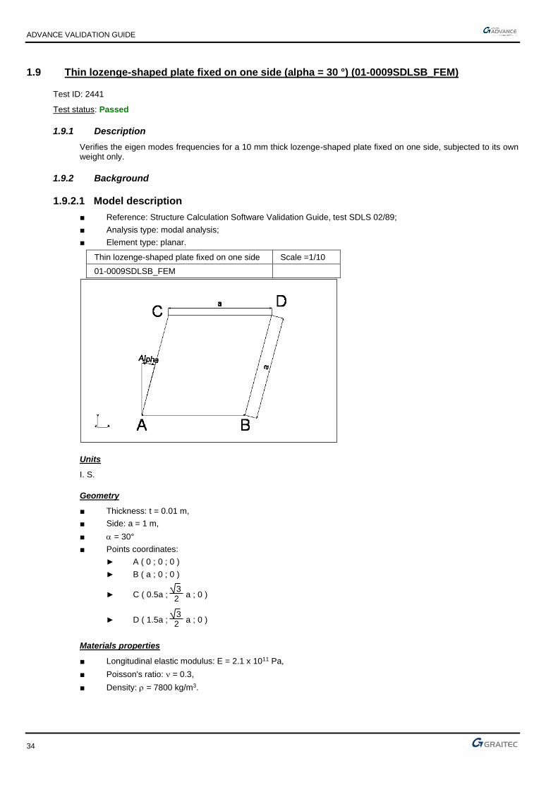
1.9 Thin lozenge-shaped plate fixed on one side (alpha = 30 °) (01-0009SDLSB_FEM)
Test ID: 2441
Test status: Passed
1.9.1 Description
Verifies the eigen modes frequencies for a 10 mm thick lozenge-shaped plate fixed on one side, subjected to its own weight only.
1.9.2 Background
1.9.2.1 Model description
■ Reference: Structure Calculation Software Validation Guide, test SDLS 02/89;
■ Analysis type: modal analysis;
■ Element type: planar.
Thin lozenge-shaped plate fixed on one side Scale =1/10
01-0009SDLSB_FEM
Units
I. S.
Geometry
■ Thickness: t = 0.01 m,
■ Side: a = 1 m,
■ = 30°
■ Points coordinates:
► A ( 0 ; 0 ; 0 )
► B ( a ; 0 ; 0 )
► C ( 0.5a ; 3 2
a ; 0 )
► D ( 1.5a ; 3 2
a ; 0 )
Materials properties
■ Longitudinal elastic modulus: E = 2.1 x 10¹¹ Pa,
■ Poisson's ratio: = 0.3,
■ Density: = 7800 kg/m3.

ADVANCE VALIDATION GUIDE
35
Boundary conditions
■ Outer: AB side fixed,
■ Inner: None.
Loading
■ External: None,
■ Internal: None.
1.9.2.2 Eigen mode frequencies relative to the angle
Reference solution
M. V. Barton formula for a lozenge of side "a" leads to the frequencies:
fj = 2a2
1i
2 )1(12
Et2
2
− where i = 1,2, or i
2 = g().
=
3.961
10.19
M. V. Barton noted the sensitivity of the result relative to the mode and the angle. He acknowledged that the i values were determined with a limited development of an insufficient order, which led to consider a reference value that is based on an experimental result, verified by an average of seven software that use the finite elements calculation method.
Finite elements modeling
■ Planar element: plate, imposed mesh,
■ 961 nodes,
■ 900 surface quadrangles.
Eigen mode shapes
1.9.2.3 Theoretical results
Solver Result name Result description Reference value
CM2 Eigen mode Eigen mode 1 frequency [Hz] 9.8987
CM2 Eigen mode Eigen mode 2 frequency [Hz] 25.4651
1.9.3 Calculated results
Result name Result description Value Error
Eigen mode Eigen mode 1 frequency [Hz] 9.82 Hz -0.80%
Eigen mode Eigen mode 2 frequency [Hz] 23.45 Hz -7.91%

ADVANCE VALIDATION GUIDE
36
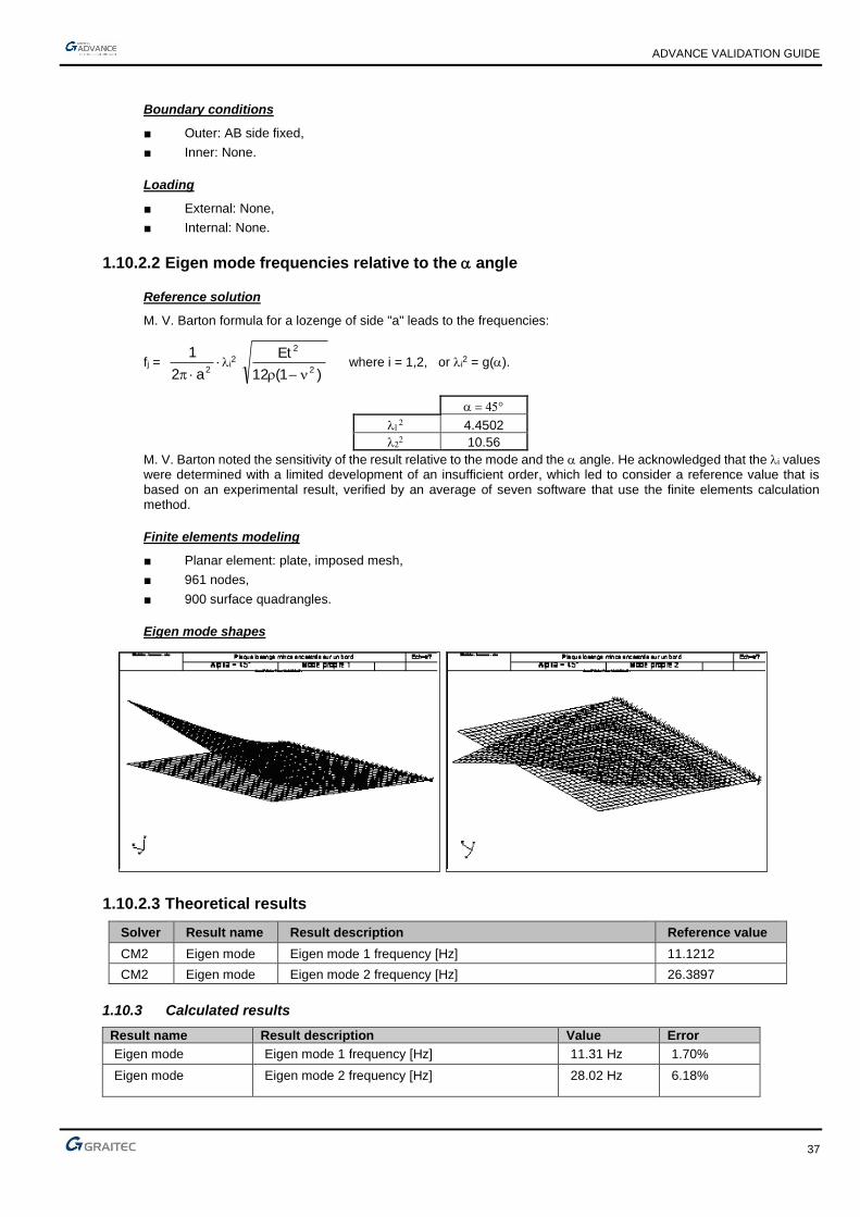
1.10 Thin lozenge-shaped plate fixed on one side (alpha = 45 °) (01-0010SDLSB_FEM)
Test ID: 2442
Test status: Passed
1.10.1 Description
Verifies the eigen modes frequencies for a 10 mm thick lozenge-shaped plate fixed on one side, subjected to its own weight only.
1.10.2 Background
1.10.2.1 Model description
■ Reference: Structure Calculation Software Validation Guide, test SDLS 02/89;
■ Analysis type: modal analysis;
■ Element type: planar.
Thin lozenge-shaped plate fixed on one side Scale =1/10
01-0010SDLSB_FEM
Units
I. S.
Geometry
■ Thickness: t = 0.01 m,
■ Side: a = 1 m,
■ = 45°
■ Points coordinates:
► A ( 0 ; 0 ; 0 )
► B ( a ; 0 ; 0 )
► C ( 2
2a ;
2
2 a ; 0 )
► D (2
22 +a ;
2
2a ; 0 )
Materials properties
■ Longitudinal elastic modulus: E = 2.1 x 10¹¹ Pa,
■ Poisson's ratio: = 0.3,
■ Density: = 7800 kg/m3.
ADVANCE VALIDATION GUIDE
37
Boundary conditions
■ Outer: AB side fixed,
■ Inner: None.
Loading
■ External: None,
■ Internal: None.
1.10.2.2 Eigen mode frequencies relative to the angle
Reference solution
M. V. Barton formula for a lozenge of side "a" leads to the frequencies:
fj = 2a2
1i
2 )1(12
Et2
2
− where i = 1,2, or i
2 = g().
=
4.4502
10.56
M. V. Barton noted the sensitivity of the result relative to the mode and the angle. He acknowledged that the i values were determined with a limited development of an insufficient order, which led to consider a reference value that is based on an experimental result, verified by an average of seven software that use the finite elements calculation method.
Finite elements modeling
■ Planar element: plate, imposed mesh,
■ 961 nodes,
■ 900 surface quadrangles.
Eigen mode shapes
1.10.2.3 Theoretical results
Solver Result name Result description Reference value
CM2 Eigen mode Eigen mode 1 frequency [Hz] 11.1212
CM2 Eigen mode Eigen mode 2 frequency [Hz] 26.3897
1.10.3 Calculated results
Result name Result description Value Error
Eigen mode Eigen mode 1 frequency [Hz] 11.31 Hz 1.70%
Eigen mode Eigen mode 2 frequency [Hz] 28.02 Hz 6.18%

ADVANCE VALIDATION GUIDE
38
1.11 Vibration mode of a thin piping elbow in plane (case 1) (01-0011SDLLB_FEM)
Test ID: 2443
Test status: Passed
1.11.1 Description
Verifies the vibration modes of a thin piping elbow (1 m radius) with fixed ends and subjected to its self weight only.
1.11.2 Background
1.11.2.1 Model description
■ Reference: Structure Calculation Software Validation Guide, test SDLL 14/89;
■ Analysis type: modal analysis (plane problem);
■ Element type: linear.
Vibration mode of a thin piping elbow in plane Scale = 1/7
Case 1 01-0011SDLLB_FEM
Units
I. S.
Geometry
■ Average radius of curvature: OA = R = 1 m,
■ Straight circular hollow section:
■ Outer diameter: de = 0.020 m,
■ Inner diameter: di = 0.016 m,
■ Section: A = 1.131 x 10⁻⁴ m2,
■ Flexure moment of inertia relative to the y-axis: Iy = 4.637 x 10⁻⁹ m4,
■ Flexure moment of inertia relative to z-axis: Iz = 4.637 x 10⁻⁹ m4,
■ Polar inertia: Ip = 9.274 x 10⁻⁹ m4.
■ Points coordinates (in m):
► O ( 0 ; 0 ; 0 )
► A ( 0 ; R ; 0 )
► B ( R ; 0 ; 0 )
Materials properties
■ Longitudinal elastic modulus: E = 2.1 x 10¹¹ Pa,
■ Poisson's ratio: = 0.3,
■ Density: = 7800 kg/m3.

ADVANCE VALIDATION GUIDE
39
Boundary conditions
■ Outer: Fixed at points A and B ,
■ Inner: None.
Loading
■ External: None,
■ Internal: None.
1.11.2.2 Eigen mode frequencies
Reference solution
The Rayleigh method applied to a thin curved beam is used to determine parameters such as:
■ in plane bending:
fj = 2
2
i
R2
A
EIz
where i = 1,2,
Finite elements modeling
■ Linear element: beam,
■ 11 nodes,
■ 10 linear elements.
Eigen mode shapes
1.11.2.3 Theoretical results
Solver Result name Result description Reference value
CM2 Eigen mode Eigen mode frequency in plane 1 [Hz] 119
CM2 Eigen mode Eigen mode frequency in plane 2 [Hz] 227
1.11.3 Calculated results
Result name Result description Value Error
Eigen mode Eigen mode frequency in plane 1 [Hz] 120.09 Hz 0.92%
Eigen mode Eigen mode frequency in plane 2 [Hz] 227.1 Hz 0.04%

ADVANCE VALIDATION GUIDE
40
1.12 Vibration mode of a thin piping elbow in plane (case 2) (01-0012SDLLB_FEM)
Test ID: 2444
Test status: Passed
1.12.1 Description
Verifies the vibration modes of a thin piping elbow (1 m radius) extended by two straight elements of length L, subjected to its self weight only.
1.12.2 Background
1.12.2.1 Model description
■ Reference: Structure Calculation Software Validation Guide, test SDLL 14/89;
■ Analysis type: modal analysis (plane problem);
■ Element type: linear.
Vibration mode of a thin piping elbow Scale = 1/11
Case 2 01-0012SDLLB_FEM
Units
I. S.
Geometry
■ Average radius of curvature: OA = R = 1 m,
■ L = 0.6 m,
■ Straight circular hollow section:
■ Outer diameter de = 0.020 m,
■ Inner diameter di = 0.016 m,
■ Section: A = 1.131 x 10⁻⁴ m2,
■ Flexure moment of inertia relative to the y-axis: Iy = 4.637 x 10⁻⁹ m4,
■ Flexure moment of inertia relative to z-axis: Iz = 4.637 x 10⁻⁹ m4,
■ Polar inertia: Ip = 9.274 x 10⁻⁹ m4.
■ Points coordinates (in m):
► O ( 0 ; 0 ; 0 )
► A ( 0 ; R ; 0 )
► B ( R ; 0 ; 0 )
► C ( -L ; R ; 0 )
► D ( R ; -L ; 0 )
Materials properties
■ Longitudinal elastic modulus: E = 2.1 x 10¹¹ Pa,

ADVANCE VALIDATION GUIDE
41
■ Poisson's ratio: = 0.3,
■ Density: = 7800 kg/m3.
Boundary conditions
■ Outer:
► Fixed at points C and D
► At A: translation restraint along y and z,
► At B: translation restraint along x and z,
■ Inner: None.
Loading
■ External: None,
■ Internal: None.
1.12.2.2 Eigen mode frequencies
Reference solution
The Rayleigh method applied to a thin curved beam is used to determine parameters such as:
■ in plane bending:
fj = 2
2
i
R2
A
EIz
where i = 1,2,
Finite elements modeling
■ Linear element: beam,
■ 23 nodes,
■ 22 linear elements.
Eigen mode shapes
1.12.2.3 Theoretical results
Solver Result name Result description Reference value
CM2 Eigen mode Eigen mode frequency in plane 1 [Hz] 94
CM2 Eigen mode Eigen mode frequency in plane 2 [Hz] 180
1.12.3 Calculated results
Result name Result description Value Error
Eigen mode Eigen mode frequency in plane 1 [Hz] 94.62 Hz 0.66%
Eigen mode Eigen mode frequency in plane 2 [Hz] 184.68 Hz 2.60%

ADVANCE VALIDATION GUIDE
42
1.13 Vibration mode of a thin piping elbow in plane (case 3) (01-0013SDLLB_FEM)
Test ID: 2445
Test status: Passed
1.13.1 Description
Verifies the vibration modes of a thin piping elbow (1 m radius) extended by two straight elements of length L, subjected to its self weight only.
1.13.2 Background
1.13.2.1 Model description
■ Reference: Structure Calculation Software Validation Guide, test SDLL 14/89;
■ Analysis type: modal analysis (plane problem);
■ Element type: linear.
Vibration mode of a thin piping elbow Scale = 1/12
Case 3 01-0013SDLLB_FEM
Units
I. S.
Geometry
■ Average radius of curvature: OA = R = 1 m,
■ Straight circular hollow section:
■ Outer diameter: de = 0.020 m,
■ Inner diameter: di = 0.016 m,
■ Section: A = 1.131 x 10⁻⁴ m2,
■ Flexure moment of inertia relative to the y-axis: Iy = 4.637 x 10⁻⁹ m4,
■ Flexure moment of inertia relative to z-axis: Iz = 4.637 x 10⁻⁹ m4,
■ Polar inertia: Ip = 9.274 x 10⁻⁹ m4.
■ Points coordinates (in m):
► O ( 0 ; 0 ; 0 )
► A ( 0 ; R ; 0 )
► B ( R ; 0 ; 0 )
► C ( -L ; R ; 0 )
► D ( R ; -L ; 0 )
Materials properties
■ Longitudinal elastic modulus: E = 2.1 x 10¹¹ Pa,
■ Poisson's ratio: = 0.3,

ADVANCE VALIDATION GUIDE
43
■ Density: = 7800 kg/m3.
Boundary conditions
■ Outer:
► Fixed at points C and Ds,
► At A: translation restraint along y and z,
► At B: translation restraint along x and z,
■ Inner: None.
Loading
■ External: None,
■ Internal: None.
1.13.2.2 Eigen mode frequencies
Reference solution
The Rayleigh method applied to a thin curved beam is used to determine parameters such as:
■ in plane bending:
fj = 2
2
i
R2
A
EIz
where i = 1,2,
Finite elements modeling
■ Linear element: beam,
■ 41 nodes,
■ 40 linear elements.
Eigen mode shapes
1.13.2.3 Theoretical results
Solver Result name Result description Reference value
CM2 Eigen mode Eigen mode frequency in plane 1 [Hz] 25.300
CM2 Eigen mode Eigen mode frequency in plane 2 [Hz] 27.000
1.13.3 Calculated results
Result name Result description Value Error
Eigen mode Eigen mode frequency in plane 1 [Hz] 24.96 Hz -1.34%
Eigen mode Eigen mode frequency in plane 2 [Hz] 26.71 Hz -1.07%

ADVANCE VALIDATION GUIDE
44
1.14 Thin circular ring hanged on an elastic element (01-0014SDLLB_FEM)
Test ID: 2446
Test status: Passed
1.14.1 Description
Verifies the first eigen modes frequencies of a circular ring hanged on an elastic element, subjected to its self weight only.
1.14.2 Background
1.14.2.1 Model description
■ Reference: Structure Calculation Software Validation Guide, test SDLL 13/89;
■ Analysis type: modal analysis, plane problem;
■ Element type: linear.
Thin circular ring hang from an elastic element Scale = 1/1
01-0014SDLLB_FEM
Units
I. S.
Geometry
■ Average radius of curvature: OB = R = 0.1 m,
■ Length of elastic element: AB = 0.0275 m ;
■ Straight rectangular section:
► Ring
Thickness: h = 0.005 m,
Width: b = 0.010 m,
Section: A = 5 x 10⁻⁵ m2,
Flexure moment of relative to the vertical axis: I = 1.042 x 10⁻¹⁰ m4,
► Elastic element
Thickness: h = 0.003 m,
Width: b = 0.010 m,
Section: A = 3 x 10⁻⁵ m2,
Flexure moment of inertia relative to the vertical axis: I = 2.25 x 10⁻¹¹ m4,
■ Points coordinates:
► O ( 0 ; 0 ),
► A ( 0 ; -0.0725 ),

ADVANCE VALIDATION GUIDE
45
► B ( 0 ; -0.1 ).
Materials properties
■ Longitudinal elastic modulus: E = 7.2 x 10¹⁰ Pa,
■ Poisson's ratio: = 0.3,
■ Density: = 2700 kg/m3.
Boundary conditions
■ Outer: Fixed in A,
■ Inner: None.
Loading
■ External: None,
■ Internal: None.
1.14.2.2 Eigen mode frequencies
Reference solutions
The reference solution was established from experimental results of a mass manufactured aluminum ring.
Finite elements modeling
■ Linear element: beam,
■ 43 nodes,
■ 43 linear elements.
Eigen mode shapes

ADVANCE VALIDATION GUIDE
46
1.14.2.3 Theoretical results
Solver Result name Result description Reference value
CM2 Eigen mode Eigen mode 1 Asymmetrical frequency [Hz] 28.80
CM2 Eigen mode Eigen mode 2 Symmetrical frequency [Hz] 189.30
CM2 Eigen mode Eigen mode 3 Asymmetrical frequency [Hz] 268.80
CM2 Eigen mode Eigen mode 4 Asymmetrical frequency [Hz] 641.00
CM2 Eigen mode Eigen mode 5 Symmetrical frequency [Hz] 682.00
CM2 Eigen mode Eigen mode 6 Asymmetrical frequency [Hz] 1063.00
1.14.3 Calculated results
Result name Result description Value Error
Eigen mode Eigen mode 1 Asymmetrical frequency [Hz] 28.81 Hz 0.03%
Eigen mode Eigen mode 2 Symmetrical frequency [Hz] 189.69 Hz 0.21%
Eigen mode Eigen mode 3 Asymmetrical frequency [Hz] 269.38 Hz 0.22%
Eigen mode Eigen mode 4 Asymmetrical frequency [Hz] 642.15 Hz 0.18%
Eigen mode Eigen mode 5 Symmetrical frequency [Hz] 683.9 Hz 0.28%
Eigen mode Eigen mode 6 Asymmetrical frequency [Hz] 1065.73 Hz 0.26%

ADVANCE VALIDATION GUIDE
47
1.15 Double fixed beam with a spring at mid span (01-0015SSLLB_FEM)
Test ID: 2447
Test status: Passed
1.15.1 Description
Verifies the vertical displacement on the middle of a beam consisting of four elements of length "l", having identical characteristics. A punctual load of -10000 N is applied.
1.15.2 Background
1.15.2.1 Model description
■ Reference: internal GRAITEC test;
■ Analysis type: linear static;
■ Element type: linear.
Units
I. S.
Geometry
■ = 1 m
■ S = 0.01 m2
■ I = 0.0001 m4
Materials properties
■ Longitudinal elastic modulus: E = 2.1 x 10¹¹ Pa,
■ Poisson's ratio: = 0.3.
Boundary conditions
■ Outer:
■ Fixed at ends x = 0 and x = 4 m,
■ Elastic support with k = EI/ rigidity
■ Inner: None.
Loading
■ External: Punctual load P = -10000 N at x = 2m,
■ Internal: None.

ADVANCE VALIDATION GUIDE
48
1.15.2.2 Displacement of the model in the linear elastic range
Reference solution
The reference vertical displacement v3, is calculated at the middle of the beam at x = 2 m.
Rigidity matrix of a plane beam:
−
−−−
−
−
−
=
EIEIEIEI
EIEIEIEI
EIEIEIEI
EIEIEIEI
460
260
6120
6120
00l
ES00
ES
260
460
6120
6120
00ES
-00ES
K
22
2323
22
2323
e
Given the symmetry / X and load of the structure, it is unnecessary to consider the degrees of freedom associated with normal work (u2, u3, u4).
The same symmetry allows the deduction of:
■ v2 = v4
■ 2 = -4
■ 3 = 0
( )( )( )( )( )( )6
5
4
3
2
1
0
0
0
0
0
4626
612612
2680
26
6120
24612
2680
26
6120
124612
2680
26
6120
24612
2646
612612
5
5
1
1
5
5
4
4
3
3
2
2
1
1
22
22
22
22
22
22
22
22
22
22
−=
−
−−−
−
−−−
−
−
+−−
−
−−−
−
−
M
R
P
M
R
v
v
v
v
v
EI
33
333
333
333
33

ADVANCE VALIDATION GUIDE
49
The elementary rigidity matrix of the spring in its local axis system, )(
)(
11
11
6
3
5U
UEIk
−
−=
, must be expressed in
the global axis system by means of the rotation matrix (90° rotation):
( )( )( )( )( )( )6
6
6
3
3
3
5
000000
010010
000000
000000
010010
000000
v
u
v
u
EIK
−
−
=
→ 344332 4
3 0
826vv
−==++
→ 344332332 0
24612vvvv ==+−−
→ y)unnecessar(usually 026826
244423222vvvv ==+−++
(3) → ( )
m 10 11905.03
612124612 03
2
3
34243332223
−−=+
−=−=−−
++−−
EIl
Pv
EI
Pvvv
Finite elements modeling
■ Linear element: beam, imposed mesh,
■ 6 nodes,
■ 4 linear elements + 1 spring,
Deformed shape
Double fixed beam with a spring at mid span
Deformed
Note: the displacement is expressed here in m
1.15.2.3 Theoretical results
Solver Result name Result description Reference value
CM2 Dz Vertical displacement on the middle of the beam [mm] -0.11905
1.15.3 Calculated results
Result name Result description Value Error
Dz Vertical displacement on the middle of the beam [mm]
-0.119048 mm
0.00%

ADVANCE VALIDATION GUIDE
50
1.16 Double fixed beam (01-0016SDLLB_FEM)
Test ID: 2448
Test status: Passed
1.16.1 Description
Verifies the eigen modes frequencies and the vertical displacement on the middle of a beam consisting of eight elements of length "l", having identical characteristics. A punctual load of -50000 N is applied.
1.16.2 Background
1.16.2.1 Model description
■ Reference: internal GRAITEC test (beams theory);
■ Analysis type: static linear, modal analysis;
■ Element type: linear.
Units
I. S.
Geometry
■ Length: l = 16 m,
■ Axial section: S=0.06 m2
■ Inertia I = 0.0001 m4
Materials properties
■ Longitudinal elastic modulus: E = 2.1 x 10¹¹ N/m2,
■ Poisson's ratio: = 0.3,
■ Density: = 7850 kg/m3
Boundary conditions
■ Outer: Fixed at both ends x = 0 and x = 8 m,
■ Inner: None.
Loading
■ External: Punctual load P = -50000 N at x = 4m,
■ Internal: None.

ADVANCE VALIDATION GUIDE
51
1.16.2.2 Displacement of the model in the linear elastic range
Reference solution
The reference vertical displacement v5, is calculated at the middle of the beam at x = 2 m.
m 05079.00001.0111.2192
1650000
192
33
5 =
==
EEI
Plv
Finite elements modeling
■ Linear element: beam, imposed mesh,
■ 9 nodes,
■ 8 elements.
Deformed shape
Double fixed beam
Deformed
1.16.2.3 Eigen mode frequencies of the model in the linear elastic range
Reference solution
Knowing that the first four eigen mode frequencies of a double fixed beam are given by the following formula:
S
IE
Lf n
n.
.
..2 2
2
= where for the first 4 eigen modes frequencies
→=
→=
→=
→=
Hz 26.228=f 8.199
Hz 15.871=f 9.120
Hz 8.095=f 67.61
Hz 2.937=f 37.22
424
323
222
121
Finite elements modeling
■ Linear element: beam, imposed mesh,
■ 9 nodes,
■ 8 elements.

ADVANCE VALIDATION GUIDE
52
Modal deformations
Double fixed beam
Mode 1
Double fixed beam
Mode 2
Double fixed beam
Mode 3

ADVANCE VALIDATION GUIDE
53
Double fixed beam
Mode 4
1.16.2.4 Theoretical results
Solver Result name Result description Reference value
CM2 Dz Vertical displacement on the middle of the beam [m] -0.05079
CM2 Eigen mode Eigen mode 1 frequency [Hz] 2.937
CM2 Eigen mode Eigen mode 2 frequency [Hz] 8.095
CM2 Eigen mode Eigen mode 3 frequency [Hz] 15.870
CM2 Eigen mode Eigen mode 4 frequency [Hz] 26.228
1.16.3 Calculated results
Result name Result description Value Error
Dz Vertical displacement on the middle of the beam [m] -0.0507937 m
-0.01%
Eigen mode Eigen mode 1 frequency [Hz] 2.94 Hz 0.10%
Eigen mode Eigen mode 2 frequency [Hz] 8.09 Hz -0.06%
Eigen mode Eigen mode 3 frequency [Hz] 15.79 Hz -0.50%
Eigen mode Eigen mode 4 frequency [Hz] 25.76 Hz -1.78%

ADVANCE VALIDATION GUIDE
54
1.17 Short beam on simple supports (on the neutral axis) (01-0017SDLLB_FEM)
Test ID: 2449
Test status: Passed
1.17.1 Description
Verifies the first eigen mode frequencies of a short beam on simple supports (the supports are located on the neutral axis), subjected to its own weight only.
1.17.2 Background
■ Reference: Structure Calculation Software Validation Guide, test SDLL 01/89;
■ Analysis type: modal analysis (plane problem);
■ Element type: linear.
Short beam on simple supports on the neutral axis Scale = 1/6
01-0017SDLLB_FEM
Units
I. S.
Geometry
■ Height: h = 0.2 m,
■ Length: l = 1 m,
■ Width: b = 0.1 m,
■ Section: A = 2 x 10⁻² m4,
■ Flexure moment of inertia relative to z-axis: Iz = 6.667 x 10⁻⁵ m4.
Materials properties
■ Longitudinal elastic modulus: E = 2.1 x 10¹¹ Pa,
■ Poisson's ratio: = 0.3,
■ Density: = 7800 kg/m3.
Boundary conditions
■ Outer:
► Hinged at A (null horizontal and vertical displacements),
► Simple support in B.
■ Inner: None.

ADVANCE VALIDATION GUIDE
55
Loading
■ External: None.
■ Internal: None.
1.17.2.1 Eigen modes frequencies
Reference solution
The bending beams equation gives, when superimposing, the effects of simple bending, shear force deformations and rotation inertia, Timoshenko formula.
The reference eigen modes frequencies are determined by a numerical simulation of this equation, independent of any software.
The eigen frequencies in tension-compression are given by:
fi =
l2
i
E where i =
2
)1i2( −
Finite elements modeling
■ Linear element: S beam, imposed mesh,
■ 10 nodes,
■ 9 linear elements.
Eigen mode shapes

ADVANCE VALIDATION GUIDE
56
1.17.2.2 Theoretical results
Solver Result name Result description Reference value
CM2 Eigen mode Eigen mode 1 frequency [Hz] 431.555
CM2 Eigen mode Eigen mode 2 frequency [Hz] 1265.924
CM2 Eigen mode Eigen mode 3 frequency [Hz] 1498.295
CM2 Eigen mode Eigen mode 4 frequency [Hz] 2870.661
CM2 Eigen mode Eigen mode 5 frequency [Hz] 3797.773
CM2 Eigen mode Eigen mode 6 frequency [Hz] 4377.837
1.17.3 Calculated results
Result name Result description Value Error
Eigen mode Eigen mode 1 frequency [Hz] 437.12 Hz 1.29%
Eigen mode Eigen mode 2 frequency [Hz] 1264.32 Hz -0.13%
Eigen mode Eigen mode 3 frequency [Hz] 1537.16 Hz 2.59%
Eigen mode Eigen mode 4 frequency [Hz] 2911.46 Hz 1.42%
Eigen mode Eigen mode 5 frequency [Hz] 3754.54 Hz -1.14%
Eigen mode Eigen mode 6 frequency [Hz] 4281.23 Hz -2.21%

ADVANCE VALIDATION GUIDE
57
1.18 Short beam on simple supports (eccentric) (01-0018SDLLB_FEM)
Test ID: 2450
Test status: Passed
1.18.1 Description
Verifies the first eigen mode frequencies of a short beam on simple supports (the supports are eccentric relative to the neutral axis).
1.18.2 Background
1.18.2.1 Model description
■ Reference: Structure Calculation Software Validation Guide, test SDLL 01/89;
■ Analysis type: modal analysis, (plane problem);
■ Element type: linear.
Short beam on simple supports (eccentric) Scale = 1/5
01-0018SDLLB_FEM
Units
I. S.
Geometry
■ Height: h = 0.2m,
■ Length: l = 1 m,
■ Width: b = 0.1 m,
■ Section: A = 2 x 10⁻² m4,
■ Flexure moment of inertia relative to z-axis: Iz = 6.667 x 10⁻⁵ m4.
Materials properties
■ Longitudinal elastic modulus: E = 2.1 x 10¹¹ Pa,
■ Poisson's ratio: = 0.3,
■ Density: = 7800 kg/m3.
Boundary conditions
■ Outer:
► Hinged at A (null horizontal and vertical displacements),
► Simple support at B.
■ Inner: None.

ADVANCE VALIDATION GUIDE
58
Loading
■ External: None.
■ Internal: None.
1.18.2.2 Eigen modes frequencies
Reference solution
The problem has no analytical solution, the solution is determined by averaging several software: Timoshenko model with shear force deformation effects and rotation inertia. The bending modes and the traction-compression are coupled.
Finite elements modeling
■ Linear element: S beam, imposed mesh,
■ 10 nodes,
■ 9 linear elements.
Eigen modes shape
Short beam on simple supports (eccentric)
Mode 1
Short beam on simple supports (eccentric)
Mode 2

ADVANCE VALIDATION GUIDE
59
Short beam on simple supports (eccentric)
Mode 3
Short beam on simple supports (eccentric)
Mode 4
Short beam on simple supports (eccentric)
Mode 5

ADVANCE VALIDATION GUIDE
60
1.18.2.3 Theoretical results
Solver Result name Result description Reference value
CM2 Eigen mode Eigen mode 1 frequency [Hz] 392.8
CM2 Eigen mode Eigen mode 2 frequency [Hz] 902.2
CM2 Eigen mode Eigen mode 3 frequency [Hz] 1591.9
CM2 Eigen mode Eigen mode 4 frequency [Hz] 2629.2
CM2 Eigen mode Eigen mode 5 frequency [Hz] 3126.2
1.18.3 Calculated results
Result name Result description Value Error
Eigen mode Eigen mode 1 frequency [Hz] 393.7 Hz 0.23%
Eigen mode Eigen mode 2 frequency [Hz] 945.35 Hz 4.78%
Eigen mode Eigen mode 3 frequency [Hz] 1595.94 Hz 0.25%
Eigen mode Eigen mode 4 frequency [Hz] 2526.22 Hz -3.92%
Eigen mode Eigen mode 5 frequency [Hz] 3118.91 Hz -0.23%

ADVANCE VALIDATION GUIDE
61
1.19 Thin square plate fixed on one side (01-0019SDLSB_FEM)
Test ID: 2451
Test status: Passed
1.19.1 Description
Verifies the first eigen modes frequencies of a thin square plate fixed on one side.
1.19.2 Background
1.19.2.1 Model description
■ Reference: Structure Calculation Software Validation Guide, test SDLS 01/89;
■ Analysis type: modal analysis;
■ Element type: planar.
Thin square plate fixed on one side Scale = 1/6
01-0019SDLSB_FEM
Units
I. S.
Geometry
■ Side: a = 1 m,
■ Thickness: t = 1 m,
■ Points coordinates in m:
► A (0 ;0 ;0)
► B (1 ;0 ;0)
► C (1 ;1 ;0)
► D (0 ;1 ;0)
Materials properties
■ Longitudinal elastic modulus: E = 2.1 x 10¹¹ Pa,
■ Poisson's ratio: = 0.3,
■ Density: = 7800 kg/m3.
Boundary conditions
■ Outer: Edge AD fixed.
■ Inner: None.
Loading
■ External: None.

ADVANCE VALIDATION GUIDE
62
■ Internal: None.
1.19.2.2 Eigen modes frequencies
Reference solution
M. V. Barton formula for a square plate with side "a", leads to:
fj = 2a2
1
i
2 )1(12
Et2
2
− where i = 1,2, . . .
i 1 2 3 4 5 6
i 3.492 8.525 21.43 27.33 31.11 54.44
Finite elements modeling
■ Planar element: shell,
■ 959 nodes,
■ 900 planar elements.
Eigen mode shapes
Thin square plate fixed on one side
Mode 1
Thin square plate fixed on one side
Mode 2

ADVANCE VALIDATION GUIDE
63
Thin square plate fixed on one side
Mode 3
1.19.2.3 Theoretical results
Solver Result name Result description Reference value
CM2 Eigen mode Eigen mode 1 frequency [Hz] 8.7266
CM2 Eigen mode Eigen mode 2 frequency [Hz] 21.3042
CM2 Eigen mode Eigen mode 3 frequency [Hz] 53.5542
CM2 Eigen mode Eigen mode 4 frequency [Hz] 68.2984
CM2 Eigen mode Eigen mode 5 frequency [Hz] 77.7448
CM2 Eigen mode Eigen mode 6 frequency [Hz] 136.0471
1.19.3 Calculated results
Result name Result description Value Error
Eigen mode Eigen mode 1 frequency [Hz] 8.67 Hz -0.65%
Eigen mode Eigen mode 2 frequency [Hz] 21.22 Hz -0.40%
Eigen mode Eigen mode 3 frequency [Hz] 53.13 Hz -0.79%
Eigen mode Eigen mode 4 frequency [Hz] 67.74 Hz -0.82%
Eigen mode Eigen mode 5 frequency [Hz] 77.15 Hz -0.77%
Eigen mode Eigen mode 6 frequency [Hz] 134.65 Hz -1.03%

ADVANCE VALIDATION GUIDE
64
1.20 Rectangular thin plate simply supported on its perimeter (01-0020SDLSB_FEM)
Test ID: 2452
Test status: Passed
1.20.1 Description
Verifies the first eigen mode frequencies of a thin rectangular plate simply supported on its perimeter.
1.20.2 Background
1.20.2.1 Model description
■ Reference: Structure Calculation Software Validation Guide, test SDLS 03/89;
■ Analysis type: modal analysis;
■ Element type: planar.
Rectangular thin plate simply supported on its perimeter Scale = 1/8
01-0020SDLSB_FEM
Units
I. S.
Geometry
■ Length: a = 1.5 m,
■ Width: b = 1 m,
■ Thickness: t = 0.01 m,
■ Points coordinates in m:
► A (0 ;0 ;0)
► B (0 ;1.5 ;0)
► C (1 ;1.5 ;0)
► D (1 ;0 ;0)
Materials properties
■ Longitudinal elastic modulus: E = 2.1 x 10¹¹ Pa,
■ Poisson's ratio: = 0.3,
■ Density: = 7800 kg/m3.
Boundary conditions
■ Outer:
► Simple support on all sides,

ADVANCE VALIDATION GUIDE
65
► For the modeling: hinged at A, B and D.
■ Inner: None.
Loading
■ External: None.
■ Internal: None.
1.20.2.2 Eigen modes frequencies
Reference solution
M. V. Barton formula for a rectangular plate with supports on all four sides, leads to:
fij = 2
[ (
a
i)2 + (
b
j)2]
)1(12
Et2
2
−
where:
i = number of half-length of wave along y ( dimension a)
j = number of half-length of wave along x ( dimension b)
Finite elements modeling
■ Planar element: shell,
■ 496 nodes,
■ 450 planar elements.
Eigen mode shapes

ADVANCE VALIDATION GUIDE
66
1.20.2.3 Theoretical results
Solver Result name Result description Reference value
CM2 Eigen mode Eigen mode “i" - “j” frequency, for i = 1; j = 1. [Hz] 35.63
CM2 Eigen mode Eigen mode “i" - “j” frequency, for i = 2; j = 1. [Hz] 68.51
CM2 Eigen mode Eigen mode “i" - “j” frequency, for i = 1; j = 2. [Hz] 109.62
CM2 Eigen mode Eigen mode “i" - “j” frequency, for i = 3; j = 1. [Hz] 123.32
CM2 Eigen mode Eigen mode “i" - “j” frequency, for i = 2; j = 2. [Hz] 142.51
CM2 Eigen mode Eigen mode “i" - “j” frequency, for i = 3; j = 2. [Hz] 197.32
1.20.3 Calculated results
Result name Result description Value Error
Eigen mode Eigen mode "i" - "j" frequency, for i = 1; j = 1 (Mode 1) [Hz]
35.58 Hz -0.14%
Eigen mode Eigen mode "i" - "j" frequency, for i = 2; j = 1 (Mode 2) [Hz]
68.29 Hz -0.32%
Eigen mode Eigen mode "i" - "j" frequency, for i = 1; j = 2 (Mode 3) [Hz]
109.98 Hz 0.33%
Eigen mode Eigen mode "i" - "j" frequency, for i = 3; j = 1 (Mode 4) [Hz]
123.02 Hz -0.24%
Eigen mode Eigen mode "i" - "j" frequency, for i = 2; j = 2 (Mode 5) [Hz]
141.98 Hz -0.37%
Eigen mode Eigen mode "i" - "j" frequency, for i = 3; j = 2 (Mode 6) [Hz]
195.55 Hz -0.90%

ADVANCE VALIDATION GUIDE
67
1.21 Cantilever beam in Eulerian buckling (01-0021SFLLB_FEM)
Test ID: 2453
Test status: Passed
1.21.1 Description
Verifies the critical load result on node 5 of a cantilever beam in Eulerian buckling. A punctual load of -100000 is applied.
1.21.2 Background
1.21.2.1 Model description
■ Reference: internal GRAITEC test (Euler theory);
■ Analysis type: Eulerian buckling;
■ Element type: linear.
Units
I. S.
Geometry
■ L= 10 m
■ S=0.01 m2
■ I = 0.0002 m4
Materials properties
■ Longitudinal elastic modulus: E = 2.0 x 10¹⁰ N/m2,
■ Poisson's ratio: = 0.1.
Boundary conditions
■ Outer: Fixed at end x = 0,
■ Inner: None.
Loading
■ External: Punctual load P = -100000 N at x = L,
■ Internal: None.
1.21.2.2 Critical load on node 5
Reference solution
The reference critical load established by Euler is:
98696.0100000
98696N 98696
L4
EIP
2
2
critique ===
=
Finite elements modeling
■ Planar element: beam, imposed mesh,

ADVANCE VALIDATION GUIDE
68
■ 5 nodes,
■ 4 elements.
Deformed shape
1.21.2.3 Theoretical results
Solver Result name Result description Reference value
CM2 Fx Critical load on node 5. [N] -98696
1.21.3 Calculated results
Result name Result description Value Error
Fx Critical load on node 5 (mode 1) [N] -100000 N -1.32%

ADVANCE VALIDATION GUIDE
69
1.22 Annular thin plate fixed on a hub (repetitive circular structure) (01-0022SDLSB_FEM)
Test ID: 2454
Test status: Passed
1.22.1 Description
Verifies the eigen mode frequencies of a thin annular plate fixed on a hub.
1.22.2 Background
1.22.2.1 Model description
■ Reference: Structure Calculation Software Validation Guide, test SDLS 04/89;
■ Analysis type: modal analysis;
■ Element type: planar element.
Annular thin plate fixed on a hub (repetitive circular structure) Scale = 1/3
01-0022SDLSB_FEM
Units
I. S.
Geometry
■ Inner radius: Ri = 0.1 m,
■ Outer radius: Re = 0.2 m,
■ Thickness: t = 0.001 m.
Material properties
■ Longitudinal elastic modulus: E = 2.1 x 10¹¹ Pa,
■ Poisson's ratio: = 0.3,
■ Density: = 7800 kg/m3.
Boundary conditions
■ Outer: Fixed on a hub at any point r = Ri.
■ Inner: None.
Loading
■ External: None.
■ Internal: None.

ADVANCE VALIDATION GUIDE
70
1.22.2.2 Eigen modes frequencies
Reference solution
The solution of determining the frequency based on Bessel functions leads to the following formula:
fij = 1
2Re2 ij
2 Et2
12(1-2)
where:
i = the number of nodal diameters
j = the number of nodal circles
and ij2 such as:
j \ i 0 1 2 3
0 13.0 13.3 14.7 18.5
1 85.1 86.7 91.7 100
Finite elements modeling
■ Planar element: plate,
■ 360 nodes,
■ 288 planar elements.
1.22.2.3 Theoretical results
Solver Result name Result description Reference value
CM2 Eigen mode Eigen mode “i" - “j” frequency, for i = 0; j = 0. [Hz] 79.26
CM2 Eigen mode Eigen mode “i" - “j” frequency, for i = 0; j = 1. [Hz] 518.85
CM2 Eigen mode Eigen mode “i" - “j” frequency, for i = 1; j = 0. [Hz] 81.09
CM2 Eigen mode Eigen mode “i" - “j” frequency, for i = 1; j = 1. [Hz] 528.61
CM2 Eigen mode Eigen mode “i" - “j” frequency, for i = 2; j = 0. [Hz] 89.63
CM2 Eigen mode Eigen mode “i" - “j” frequency, for i = 2; j = 1. [Hz] 559.09
CM2 Eigen mode Eigen mode “i" - “j” frequency, for i = 3; j = 0. [Hz] 112.79
CM2 Eigen mode Eigen mode “i" - “j” frequency, for i = 3; j = 1. [Hz] 609.70
1.22.3 Calculated results
Result name Result description Value Error
Eigen mode Eigen mode "i" - "j" frequency, for i = 0; j = 0 (Mode 1) [Hz] 79.67 Hz 0.52%
Eigen mode Eigen mode "i" - "j" frequency, for i = 0; j = 1 (Mode 18) [Hz] 524.76 Hz 1.14%
Eigen mode Eigen mode "i" - "j" frequency, for i = 1; j = 0 (Mode 2) [Hz] 81.15 Hz 0.07%
Eigen mode Eigen mode "i" - "j" frequency, for i = 1; j = 1 (Mode 20) [Hz] 532.44 Hz 0.72%
Eigen mode Eigen mode "i" - "j" frequency, for i = 2; j = 0 (Mode 4) [Hz] 89.13 Hz -0.56%
Eigen mode Eigen mode “i" - “j” frequency, for i = 2; j = 1 (Mode 22) [Hz] 555.51 Hz -0.64%
Eigen mode Eigen mode "i" - "j" frequency, for i = 3; j = 0 (Mode 7) [Hz] 111.15 Hz -1.45%
Eigen mode Eigen mode "i" - "j" frequency, for i = 3; j = 1 (Mode 25) [Hz] 600.16 Hz -1.56%

ADVANCE VALIDATION GUIDE
71
1.23 Bending effects of a symmetrical portal frame (01-0023SDLLB_FEM)
Test ID: 2455
Test status: Passed
1.23.1 Description
Verifies the first eigen mode frequencies of a symmetrical portal frame with fixed supports.
1.23.2 Background
1.23.2.1 Model description
■ Reference: Structure Calculation Software Validation Guide, test SDLL 01/89;
■ Analysis type: modal analysis;
■ Element type: linear.
Bending effects of a symmetrical portal frame Scale = 1/5
01-0023SDLLB_FEM
Units
I. S.
Geometry
■ Straight rectangular sections for beams and columns:
■ Thickness: h = 0.0048 m,
■ Width: b = 0.029 m,
■ Section: A = 1.392 x 10⁻⁴ m2,
■ Flexure moment of inertia relative to z-axis: Iz = 2.673 x 10⁻¹⁰ m4,
■ Points coordinates in m:
A B C D E F
x -0.30 0.30 -0.30 0.30 -0.30 0.30
y 0 0 0.36 0.36 0.81 0.81
Materials properties
■ Longitudinal elastic modulus: E = 2.1 x 10¹¹ Pa,
■ Poisson's ratio: = 0.3,
■ Density: = 7800 kg/m3.
Boundary conditions
■ Outer: Fixed at A and B,
■ Inner: None.

ADVANCE VALIDATION GUIDE
72
Loading
■ External: None.
■ Internal: None.
1.23.2.2 Eigen modes frequencies
Reference solution
Dynamic radius method (slender beams theory).
Finite elements modeling
■ Linear element: beam,
■ 60 nodes,
■ 60 linear elements.
Deformed shape
Bending effects of a symmetrical portal frame Scale = 1/7
Mode 13
1.23.2.3 Theoretical results
Solver Result name Result description Reference value
CM2 Eigen mode Eigen mode 1 antisymmetric frequency [Hz] 8.8
CM2 Eigen mode Eigen mode 2 antisymmetric frequency [Hz] 29.4
CM2 Eigen mode Eigen mode 3 symmetric frequency [Hz] 43.8
CM2 Eigen mode Eigen mode 4 symmetric frequency [Hz] 56.3
CM2 Eigen mode Eigen mode 5 antisymmetric frequency [Hz] 96.2
CM2 Eigen mode Eigen mode 6 symmetric frequency [Hz] 102.6
CM2 Eigen mode Eigen mode 7 antisymmetric frequency [Hz] 147.1
CM2 Eigen mode Eigen mode 8 symmetric frequency [Hz] 174.8
CM2 Eigen mode Eigen mode 9 antisymmetric frequency [Hz] 178.8
CM2 Eigen mode Eigen mode 10 antisymmetric frequency [Hz] 206
CM2 Eigen mode Eigen mode 11 symmetric frequency [Hz] 266.4
CM2 Eigen mode Eigen mode 12 antisymmetric frequency [Hz] 320
CM2 Eigen mode Eigen mode 13 symmetric frequency [Hz] 335
1.23.3 Calculated results

ADVANCE VALIDATION GUIDE
73
Result name Result description Value Error
Eigen mode Eigen mode 1 antisymmetric frequency [Hz] 8.78 Hz -0.23%
Eigen mode Eigen mode 2 antisymmetric frequency [Hz] 29.43 Hz 0.10%
Eigen mode Eigen mode 3 symmetric frequency [Hz] 43.85 Hz 0.11%
Eigen mode Eigen mode 4 symmetric frequency [Hz] 56.3 Hz 0.00%
Eigen mode Eigen mode 5 antisymmetric frequency [Hz] 96.05 Hz -0.16%
Eigen mode Eigen mode 6 symmetric frequency [Hz] 102.7 Hz 0.10%
Eigen mode Eigen mode 7 antisymmetric frequency [Hz] 147.08 Hz -0.01%
Eigen mode Eigen mode 8 symmetric frequency [Hz] 174.96 Hz 0.09%
Eigen mode Eigen mode 9 antisymmetric frequency [Hz] 178.92 Hz 0.07%
Eigen mode Eigen mode 10 antisymmetric frequency [Hz] 206.23 Hz 0.11%
Eigen mode Eigen mode 11 symmetric frequency [Hz] 266.62 Hz 0.08%
Eigen mode Eigen mode 12 antisymmetric frequency [Hz] 319.95 Hz -0.02%
Eigen mode Eigen mode 13 symmetric frequency [Hz] 334.96 Hz -0.01%

ADVANCE VALIDATION GUIDE
74
1.24 Slender beam on two fixed supports (01-0024SSLLB_FEM)
Test ID: 2456
Test status: Passed
1.24.1 Description
A straight slender beam with fixed ends is loaded with a uniform load, several punctual loads and a torque. The shear force, bending moment, vertical displacement and horizontal reaction are verified.
1.24.2 Background
1.24.2.1 Model description
■ Reference: Structure Calculation Software Validation Guide, test SSLL 01/89;
■ Analysis type: linear static;
■ Element type: linear.
Slender beam on two fixed supports Scale = 1/4
01-0024SSLLB_FEM
Units
I. S.
Geometry
■ Length: L = 1 m,
■ Beam inertia: I = 1.7 x 10⁻⁸ m4.
Materials properties
■ Longitudinal elastic modulus: E = 2.1 x 10¹¹ Pa.
Boundary conditions
■ Outer: Fixed at A and B,
■ Inner: None.
Loading
■ External:
► Uniformly distributed load from A to B: py = p = -24000 N/m,
► Punctual load at D: Fx = F1 = 30000 N,
► Torque at D: Cz = C = -3000 Nm,
► Punctual load at E: Fx = F2 = 10000 N,
► Punctual load at E: Fy = F = -20000 N.
■ Internal: None.

ADVANCE VALIDATION GUIDE
75
1.24.2.2 Shear force at G
Reference solution
Analytical solution:
■ Shear force at G: VG
VG = 0.216F – 1.26 L
C
Finite elements modeling
■ Linear element: beam,
■ 5 nodes,
■ 4 linear elements.
Results shape
Slender beam on two fixed supports Scale = 1/5
Shear force
1.24.2.3 Bending moment in G
Reference solution
Analytical solution:
■ Bending moment at G: MG
MG = pL2
24 - 0.045LF – 0.3C
Finite elements modeling
■ Linear element: beam,
■ 5 nodes,
■ 4 linear elements.

ADVANCE VALIDATION GUIDE
76
Results shape
Slender beam on two fixed supports Scale = 1/5
Bending moment
1.24.2.4 Vertical displacement at G
Reference solution
Analytical solution:
■ Vertical displacement at G: vG
vG = pl4
384EI +
0.003375FL3
EI +
0.015CL2
EI
Finite elements modeling
■ Linear element: beam,
■ 5 nodes,
■ 4 linear elements.
Results shape
Slender beam on two fixed supports Scale = 1/4
Deformed

ADVANCE VALIDATION GUIDE
77
1.24.2.5 Horizontal reaction at A
Reference solution
Analytical solution:
■ Horizontal reaction at A: HA
HA = -0.7F1 –0.3F2
Finite elements modeling
■ Linear element: beam,
■ 5 nodes,
■ 4 linear elements.
1.24.2.6 Theoretical results
Solver Result name Result description Reference value
CM2 Fz Shear force in point G. [N] -540
CM2 My Bending moment in point G. [Nm] -2800
CM2 Dz Vertical displacement in point G. [cm] -4.90
CM2 Fx Horizontal reaction in point A. [N] 24000
1.24.3 Calculated results
Result name Result description Value Error
Fz Shear force in point G [N] -540 N 0.00%
My Bending moment in point G [Nm] -2800 N*m 0.00%
DZ Vertical displacement in point G [cm] -4.90485 cm -0.10%
Fx Horizontal reaction in point A [N] 24000 N 0.00%

ADVANCE VALIDATION GUIDE
78
1.25 Slender beam on three supports (01-0025SSLLB_FEM)
Test ID: 2457
Test status: Passed
1.25.1 Description
A straight slender beam on three supports is loaded with two punctual loads. The bending moment, vertical displacement and reaction on the center are verified.
1.25.2 Background
1.25.2.1 Model description
■ Reference: Structure Calculation Software Validation Guide, test SSLL 03/89;
■ Analysis type: static (plane problem);
■ Element type: linear.
Slender beam on three supports Scale = 1/49
01-0025SSLLB_FEM
Units
I. S.
Geometry
■ Length: L = 3 m,
■ Beam inertia: I = 6.3 x 10⁻⁴ m4.
Materials properties
Longitudinal elastic modulus: E = 2.1 x 10¹¹ Pa.
Boundary conditions
■ Outer:
► Hinged at A,
► Elastic support at B (Ky = 2.1 x 10⁶ N/m),
► Simple support at C.
■ Inner: None.
Loading
■ External: 2 punctual loads F = Fy = -42000N.
■ Internal: None.

ADVANCE VALIDATION GUIDE
79
1.25.2.2 Bending moment at B
Reference solution
The resolution of the hyperstatic system of the slender beam leads to:
k = Ky3L
EI6
■ Bending moment at B: MB
MB = ± 2
L
)k8(
F)k26(
+
+−
Finite elements modeling
■ Linear element: beam,
■ 5 nodes,
■ 4 linear elements.
Results shape
Slender beam on three supports Scale = 1/49
Bending moment
1.25.2.3 Reaction in B
Reference solution
■ Compression force in the spring: VB
VB = -11F8 + k
Finite elements modeling
■ Linear element: beam,
■ 5 nodes,
■ 4 linear elements.
1.25.2.4 Vertical displacement at B
Reference solution
■ Deflection at the spring location: vB

ADVANCE VALIDATION GUIDE
80
vB = 11F
Ky(8 + k)
Finite elements modeling
■ Linear element: beam,
■ 5 nodes,
■ 4 linear elements.
Results shape
Slender beam on three supports
Deformed
1.25.2.5 Theoretical results
Solver Result name Result description Reference value
CM2 My Bending moment in point B. [Nm] -63000
CM2 DZ Vertical displacement in point B. [cm] -1.00
CM2 Fz Reaction in point B. [N] -21000
1.25.3 Calculated results
Result name Result description Value Error
My Bending moment in point B [Nm] -63000 N*m 0.00%
DZ Vertical displacement in point B [cm] -1 cm 0.00%
Fz Reaction in point B [N] -21000 N 0.00%

ADVANCE VALIDATION GUIDE
81
1.26 Bimetallic: Fixed beams connected to a stiff element (01-0026SSLLB_FEM)
Test ID: 2458
Test status: Passed
1.26.1 Description
Two beams fixed at one end and rigidly connected to an undeformable beam is loaded with a punctual load. The deflection, vertical reaction and bending moment are verified in several points.
1.26.2 Background
1.26.2.1 Model description
■ Reference: Structure Calculation Software Validation Guide, test SSLL 05/89;
■ Analysis type: linear static;
■ Element type: linear.
Fixed beams connected to a stiff element Scale = 1/10
01-0026SSLLB_FEM
Units
I. S.
Geometry
■ Lengths:
► L = 2 m,
► l = 0.2 m,
■ Beams inertia moment: I = (4/3) x 10-8 m4,
■ The beam sections are squared, of side: 2 x 10⁻² m.
Materials properties
■ Longitudinal elastic modulus: E = 2 x 10¹¹ Pa.
Boundary conditions
■ Outer: Fixed in A and C,
■ Inner: The tangents to the deflection of beams AB and CD at B and D remain horizontal; practically, we restraint translations along x and z at nodes B and D.
Loading
■ External: In D: punctual load F = Fy = -1000N.
■ Internal: None.

ADVANCE VALIDATION GUIDE
82
1.26.2.2 Deflection at B and D
Reference solution
The theory of slender beams bending (Euler-Bernouilli formula) leads to a deflection at B and D:
The resolution of the hyperstatic system of the slender beam leads to:
vB = vD = FL3
24EI
Finite elements modeling
■ Linear element: beam,
■ 4 nodes,
■ 3 linear elements.
Results shape
Fixed beams connected to a stiff element Scale = 1/10
Deformed
1.26.2.3 Vertical reaction at A and C
Reference solution
Analytical solution.
Finite elements modeling
■ Linear element: beam,
■ 4 nodes,
■ 3 linear elements.
1.26.2.4 Bending moment at A and C
Reference solution
Analytical solution.
Finite elements modeling
■ Linear element: beam,
■ 4 nodes,
■ 3 linear elements

ADVANCE VALIDATION GUIDE
83
1.26.2.5 Theoretical results
Solver Result name Result description Reference value
CM2 D Deflection in point B [m] 0.125
CM2 D Deflection in point D [m] 0.125
CM2 Fz Vertical reaction in point A [N] -500
CM2 Fz Vertical reaction in point C [N] -500
CM2 My Bending moment in point A [Nm] 500
CM2 My Bending moment in point C [Nm] 500
1.26.3 Calculated results
Result name Result description Value Error
D Deflection in point B [m] 0.125376 m 0.30%
D Deflection in point D [m] 0.125376 m 0.30%
Fz Vertical reaction in point A [N] -500 N 0.00%
Fz Vertical reaction in point C [N] -500 N 0.00%
My Bending moment in point A [Nm] 500.083 N*m 0.02%
My Bending moment in point C [Nm] 500.083 N*m 0.02%

ADVANCE VALIDATION GUIDE
84
1.27 Fixed thin arc in planar bending (01-0027SSLLB_FEM)
Test ID: 2459
Test status: Passed
1.27.1 Description
Arc of a circle fixed at one end, subjected to two punctual loads and a torque at its free end. The horizontal displacement, vertical displacement and rotation about Z-axis are verified.
1.27.2 Background
1.27.2.1 Model description
■ Reference: Structure Calculation Software Validation Guide, test SSLL 06/89;
■ Analysis type: static linear (plane problem);
■ Element type: linear.
Fixed thin arc in planar bending Scale = 1/24
01-0027SSLLB_FEM
Units
I. S.
Geometry
■ Medium radius: R = 3 m ,
■ Circular hollow section:
► de = 0.02 m,
► di = 0.016 m,
► A = 1.131 x 10⁻⁴ m2,
► Ix = 4.637 x 10⁻⁹ m4.
Materials properties
Longitudinal elastic modulus: E = 2 x 10¹¹ Pa.
Boundary conditions
■ Outer: Fixed in A.
■ Inner: None.
Loading
■ External:
At B:
► punctual load F1 = Fx = 10 N,

ADVANCE VALIDATION GUIDE
85
► punctual load F2 = Fy = 5 N,
► bending moment about Oz, Mz = 8 Nm.
■ Internal: None.
1.27.2.2 Displacements at B
Reference solution
At point B:
■ displacement parallel to Ox: u = R2
4EI [F1R + 2F2R + 4Mz]
■ displacement parallel to Oy: v = R2
4EI [2F1R + (3 - 8)F2R + 2( - 2)Mz]
■ rotation around Oz: = R
4EI [4F1R + 2( - 2)F2R + 2Mz]
Finite elements modeling
■ Linear element: beam,
■ 31 nodes,
■ 30 linear elements.
Results shape
Fixed thin arc in planar bending Scale = 1/19
Deformed
1.27.2.3 Theoretical results
Solver Result name Result description Reference value
CM2 DX Horizontal displacement in point B [m] 0.3791
CM2 DZ Vertical displacement in point B [m] 0.2417
CM2 RY Rotation about Z-axis in point B [rad] -0.1654
1.27.3 Calculated results
Result name Result description Value Error
DX Horizontal displacement in point B [m] 0.378914 m -0.05%
DZ Vertical displacement in point B [m] 0.241738 m 0.02%
RY Rotation about Z-axis in point B [rad] -0.165362 Rad 0.02%

ADVANCE VALIDATION GUIDE
86
1.28 Fixed thin arc in out of plane bending (01-0028SSLLB_FEM)
Test ID: 2460
Test status: Passed
1.28.1 Description
An arc of a circle fixed at one end is loaded with a punctual force at its free end, perpendicular to the plane. The out of plane displacement, torsion moment and bending moment are verified.
1.28.2 Background
1.28.2.1 Model description
■ Reference: Structure Calculation Software Validation Guide, test SSLL 07/89;
■ Analysis type: static linear;
■ Element type: linear.
Fixed thin arc in out of plane bending Scale = 1/6
01-0028SSLLB_FEM
Units
I. S.
Geometry
■ Medium radius: R = 1 m ,
■ Circular hollow section:
► de = 0.02 m,
► di = 0.016 m,
► A = 1.131 x 10⁻⁴ m2,
► Ix = 4.637 x 10⁻⁹ m4.
Materials properties
■ Longitudinal elastic modulus: E = 2 x 10¹¹ Pa,
■ Poisson's ratio: = 0.3.
Boundary conditions
■ Outer: Fixed at A.
■ Inner: None.

ADVANCE VALIDATION GUIDE
87
Loading
■ External: Punctual force in B perpendicular on the plane: Fz = F = 100 N.
■ Internal: None.
1.28.2.2 Displacements at B
Reference solution
Displacement out of plane at point B:
uB = FR3
EIx [
4 +
EIx KT
(3
4 - 2)]
where KT is the torsional rigidity for a circular section (torsion constant is 2Ix).
KT = 2GIx = EIx
1 + uB =
FR3
EIx [
4 + (1 + ) (
3
4 - 2)]
Finite elements modeling
■ Linear element: beam,
■ 46 nodes,
■ 45 linear elements.
1.28.2.3 Moments at = 15°
Reference solution
■ Torsion moment: Mx’ = Mt = FR(1 - sin)
■ Bending moment: Mz’ = Mf = -FRcos
Finite elements modeling
■ Linear element: beam,
■ 46 nodes,
■ 45 linear elements.
1.28.2.4 Theoretical results
Solver Result name Result description Reference value
CM2 D Displacement out of plane in point B [m] 0.13462
CM2 Mx Torsion moment in = 15° [Nm] 74.1180
CM2 Mz Bending moment in = 15° [Nm] -96.5925
1.28.3 Calculated results
Result name Result description Value Error
D Displacement out of plane in point B [m] 0.135156 m 0.40%
Mx Torsion moment in Theta = 15° [Nm] 74.103 N*m -0.02%
Mz Bending moment in Theta = 15° [Nm] 96.5925 N*m 0.00%

ADVANCE VALIDATION GUIDE
88
1.29 Double hinged thin arc in planar bending (01-0029SSLLB_FEM)
Test ID: 2461
Test status: Passed
1.29.1 Description
Verifies the rotation about Z-axis, the vertical displacement and the horizontal displacement on several points of a double hinged thin arc in planar bending.
1.29.2 Background
1.29.2.1 Model description
■ Reference: Structure Calculation Software Validation Guide, test SSLL 08/89;
■ Analysis type: static linear (plane problem);
■ Element type: linear.
Double hinged thin arc in planar bending Scale = 1/8
01-0029SSLLB_FEM
Units
I. S.
Geometry
■ Medium radius: R = 1 m ,
■ Circular hollow section:
► de = 0.02 m,
► di = 0.016 m,
► A = 1.131 x 10⁻⁴ m2,
► Ix = 4.637 x 10⁻⁹ m4.
Materials properties
■ Longitudinal elastic modulus: E = 2 x 10¹¹ Pa,
■ Poisson's ratio: = 0.3.
Boundary conditions
■ Outer:
► Hinge at A,
► At B: allowed rotation along z, vertical displacement restrained along y.
■ Inner: None.

ADVANCE VALIDATION GUIDE
89
Loading
■ External: Punctual load at C: Fy = F = - 100 N.
■ Internal: None.
1.29.2.2 Displacements at A, B and C
Reference solution
■ Rotation about z-axis
A = - B = (
2 - 1)
FR22EI
■ Displacement;
Vertical at C: vC =
8
FREA
+ ( 3
4 - 2)
FR3
2EI
Horizontal at B: uB = FR2EA
- FR3
2EI
Finite elements modeling
■ Linear element: beam,
■ 37 nodes,
■ 36 linear elements.
Displacements shape
Fixed thin arc in planar bending Scale = 1/11
Deformed
1.29.2.3 Theoretical results
Solver Result name Result description Reference value
CM2 RY Rotation about Z-axis in point A [rad] 0.030774
CM2 RY Rotation about Z-axis in point B [rad] -0.030774
CM2 DZ Vertical displacement in point C [cm] -1.9206
CM2 DX Horizontal displacement in point B [cm] 5.3912
1.29.3 Calculated results
Result name Result description Value Error
RY Rotation about Z-axis in point A [rad] 0.0307785 Rad 0.01%
RY Rotation about Z-axis in point B [rad] -0.0307785 Rad -0.01%
DZ Vertical displacement in point C [cm] -1.92019 cm 0.02%
DX Horizontal displacement in point B [cm] 5.386 cm -0.10%

ADVANCE VALIDATION GUIDE
90
1.30 Portal frame with lateral connections (01-0030SSLLB_FEM)
Test ID: 2462
Test status: Passed
1.30.1 Description
Verifies the rotation about z-axis and the bending moment on a portal frame with lateral connections.
1.30.2 Background
1.30.2.1 Model description
■ Reference: Structure Calculation Software Validation Guide, test SSLL 10/89;
■ Analysis type: static linear;
■ Element type: linear.
Portal frame with lateral connections Scale = 1/21
01-0030SSLLB_FEM
Units
I. S.
Geometry
Beam Length Moment of inertia
AB lAB = 4 m IAB =
643
x 10-8 m4
AC lAC = 1 m IAC =
112
x 10-8 m4
AD lAD = 1 m IAD =
112
x 10-8 m4
AE lAE = 2 m IAE =
43 x 10-8 m4
■ G is in the middle of DA.
■ The beams have square sections:
► AAB = 16 x 10-4 m
► AAD = 1 x 10⁻⁴ m
► AAC = 1 x 10⁻⁴ m
► AAE = 4 x 10⁻⁴ m

ADVANCE VALIDATION GUIDE
91
Materials properties
Longitudinal elastic modulus: E = 2 x 10¹¹ Pa,
Boundary conditions
■ Outer:
► Fixed at B, D and E,
► Hinge at C,
■ Inner: None.
Loading
■ External:
► Punctual force at G: Fy = F = - 105 N,
► Distributed load on beam AD: p = - 103 N/m.
■ Internal: None.
1.30.2.2 Displacements at A
Reference solution
Rotation at A about z-axis:
We say: kAn = EIAn
lAn where n = B, C, D or E
K = kAB + kAD + kAE + 34 kAC
rAn = kAn
K
C1 = FlAD
8 -
plAB2
12
= C1
4K
Finite elements modeling
■ Linear element: beam,
■ 6 nodes,
■ 5 linear elements.
Displacements shape
Portal frame with lateral connections
Deformed

ADVANCE VALIDATION GUIDE
92
1.30.2.3 Moments in A
Reference solution
■ MAB = plAB
2
12 + rAB x C1
■ MAD = - FlAD
8 + rAD x C1
■ MAE = rAE x C1
■ MAC = rAC x C1
Finite elements modeling
■ Linear element: beam,
■ 6 nodes,
■ 5 linear elements
1.30.2.4 Theoretical results
Solver Result name Result description Reference value
CM2 RY Rotation about z-axis in point A [rad] -0.227118
CM2 My Bending moment in point A (MAB) [Nm] 11023.72
CM2 My Bending moment in point A (MAC) [Nm] 113.559
CM2 My Bending moment in point A (MAD) [Nm] 12348.588
CM2 My Bending moment in point A (MAE) [Nm] 1211.2994
1.30.3 Calculated results
Result name Result description Value Error
RY Rotation Theta about z-axis in point A [rad] -0.227401 Rad -0.12%
My Bending moment in point A (Moment AB) [Nm] 11021 N*m -0.02%
My Bending moment in point A (Moment AC) [Nm] 113.704 N*m 0.13%
My Bending moment in point A (Moment AD) [Nm] 12347.5 N*m -0.01%
My Bending moment in point A (Moment AE) [Nm] 1212.77 N*m 0.12%

ADVANCE VALIDATION GUIDE
93
1.31 Truss with hinged bars under a punctual load (01-0031SSLLB_FEM)
Test ID: 2463
Test status: Passed
1.31.1 Description
Verifies the horizontal and the vertical displacement in several points of a truss with hinged bars, subjected to a punctual load.
1.31.2 Background
■ Reference: Structure Calculation Software Validation Guide, test SSLL 11/89;
■ Analysis type: static linear (plane problem);
■ Element type: linear.
1.31.2.1 Model description
Truss with hinged bars under a punctual load Scale = 1/10
01-0031SSLLB_FEM
Units
I. S.
Geometry
Elements Length (m) Area (m2)
AC 0.5 2 2 x 10⁻⁴
CB 0.5 2 2 x 10⁻⁴
CD 2.5 1 x 10⁻⁴
BD 2 1 x 10⁻⁴
Materials properties
Longitudinal elastic modulus: E = 1.962 x 10¹¹ Pa.
Boundary conditions
■ Outer: Hinge at A and B,
■ Inner: None.
Loading
■ External: Punctual force at D: Fy = F = - 9.81 x 10³ N.

ADVANCE VALIDATION GUIDE
94
■ Internal: None.
1.31.2.2 Displacements at C and D
Reference solution
Displacement method.
Finite elements modeling
■ Linear element: beam,
■ 4 nodes,
■ 4 linear elements.
Displacements shape
Truss with hinged bars under a punctual load Scale = 1/9
Deformed
1.31.2.3 Theoretical results
Solver Result name Result description Reference value
CM2 DX Horizontal displacement in point C [mm] 0.26517
CM2 DX Horizontal displacement in point D [mm] 3.47902
CM2 DZ Vertical displacement in point C [mm] 0.08839
CM2 DZ Vertical displacement in point D [mm] -5.60084
1.31.3 Calculated results
Result name Result description Value Error
DX Horizontal displacement in point C [mm] 0.264693 mm -0.18%
DX Horizontal displacement in point D [mm] 3.47531 mm -0.11%
DZ Vertical displacement in point C [mm] 0.0881705 mm -0.25%
DZ Vertical displacement in point D [mm] -5.595 mm 0.10%

ADVANCE VALIDATION GUIDE
95
1.32 Beam on elastic soil, free ends (01-0032SSLLB_FEM)
Test ID: 2464
Test status: Passed
1.32.1 Description
A beam under 3 punctual loads lays on a soil of constant linear stiffness. The bending moment, vertical displacement and rotation about z-axis on several points of the beam are verified.
1.32.2 Background
1.32.2.1 Model description
■ Reference: Structure Calculation Software Validation Guide, test SSLL 15/89;
■ Analysis type: static linear (plane problem);
■ Element type: linear.
Beam on elastic soil, free ends Scale = 1/21
01-0032SSLLB_FEM
Units
I. S.
Geometry
■ L = ( 10 )/2,
■ I = 10-4 m4.
Materials properties
Longitudinal elastic modulus: E = 2.1 x 10¹¹ Pa.
Boundary conditions
■ Outer:
► Free A and B extremities,
► Constant linear stiffness of soil ky = K = 840000 N/m2.
■ Inner: None.
Loading
■ External: Punctual load at A, C and B: Fy = F = - 10000 N.
■ Internal: None.
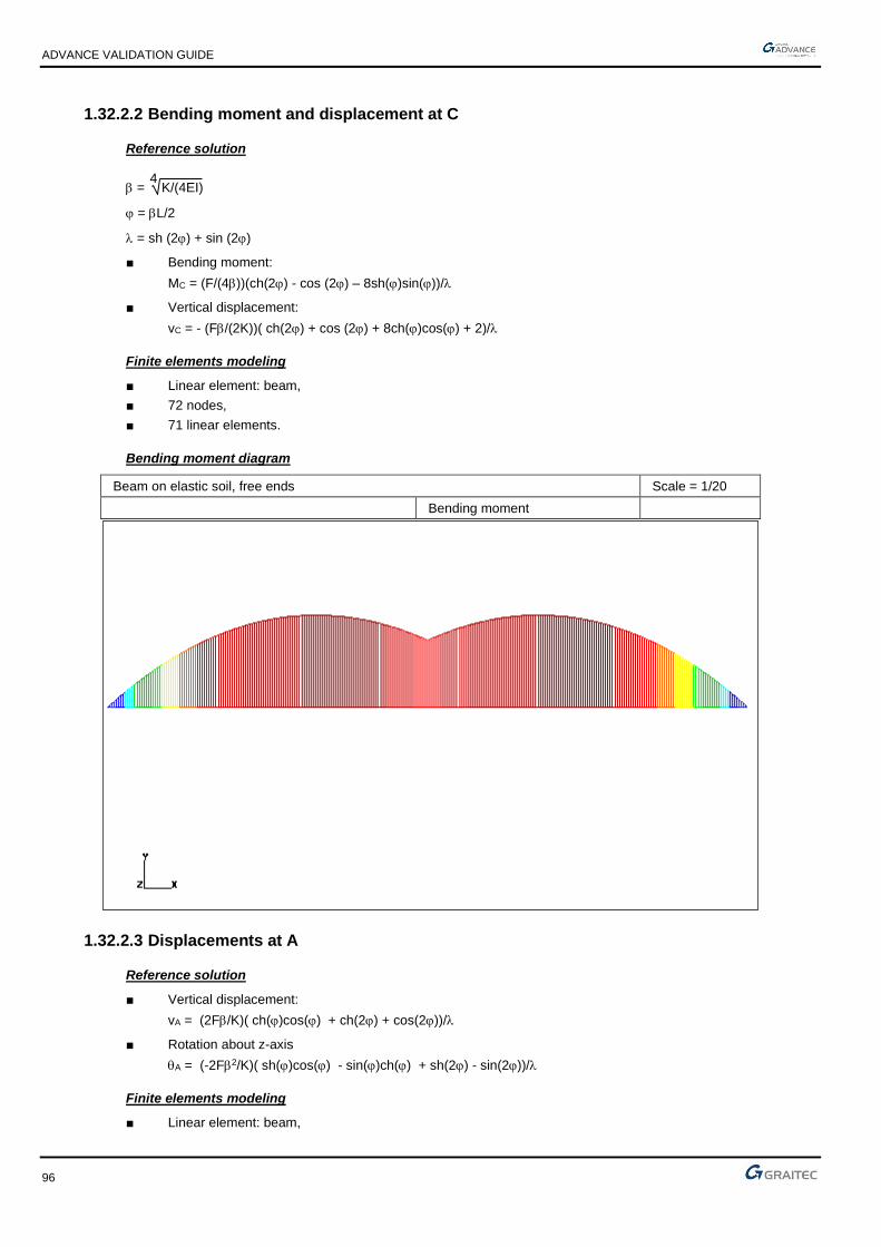
ADVANCE VALIDATION GUIDE
96
1.32.2.2 Bending moment and displacement at C
Reference solution
= 4
K/(4EI)
= L/2
= sh (2) + sin (2)
■ Bending moment:
MC = (F/(4))(ch(2) - cos (2) – 8sh()sin())/
■ Vertical displacement:
vC = - (F/(2K))( ch(2) + cos (2) + 8ch()cos() + 2)/
Finite elements modeling
■ Linear element: beam,
■ 72 nodes,
■ 71 linear elements.
Bending moment diagram
Beam on elastic soil, free ends Scale = 1/20
Bending moment
1.32.2.3 Displacements at A
Reference solution
■ Vertical displacement:
vA = (2F/K)( ch()cos() + ch(2) + cos(2))/
■ Rotation about z-axis
A = (-2F2/K)( sh()cos() - sin()ch() + sh(2) - sin(2))/
Finite elements modeling
■ Linear element: beam,

ADVANCE VALIDATION GUIDE
97
■ 72 nodes,
■ 71 linear elements
1.32.2.4 Theoretical results
Solver Result name Result description Reference value
CM2 My Bending moment in point C [Nm] 5759
CM2 Dz Vertical displacement in point C [m] -0.006844
CM2 Dz Vertical displacement in point A [m] -0.007854
CM2 RY Rotation about z-axis in point A [rad] -0.000706
1.32.3 Calculated results
Result name Result description Value Error
My Bending moment in point C [Nm] 5779.54 N*m 0.36%
Dz Vertical displacement in point C [m] -0.00684369 m 0.00%
Dz Vertical displacement in point A [m] -0.00786073 m -0.09%
RY Rotation Theta about z-axis in point A [rad] -0.000707427 Rad
-0.20%
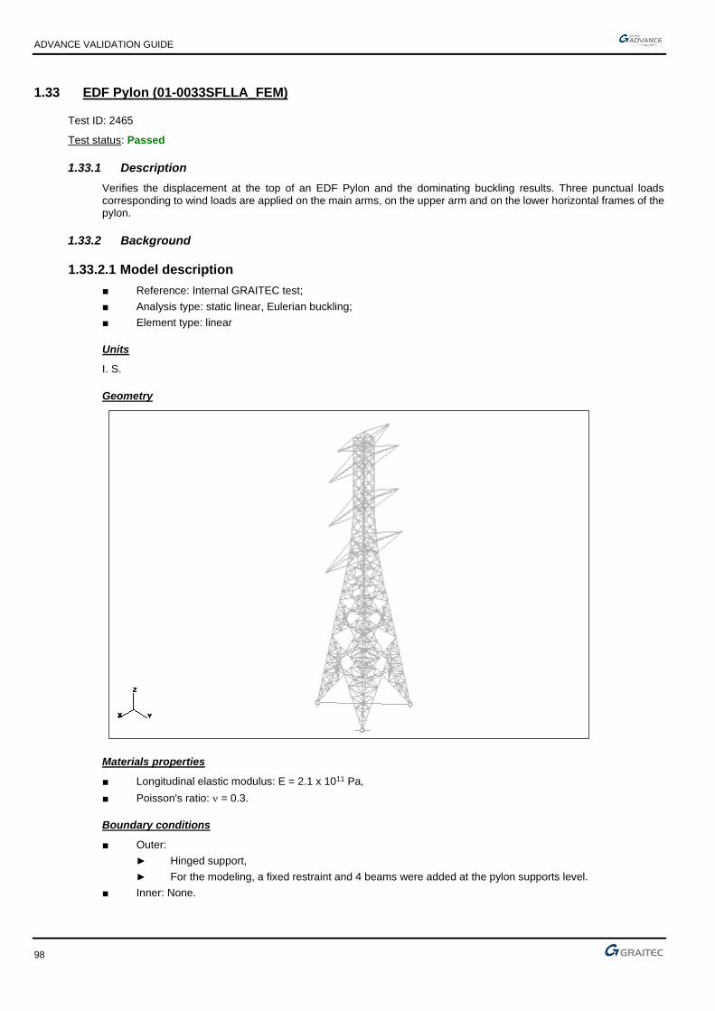
ADVANCE VALIDATION GUIDE
98
1.33 EDF Pylon (01-0033SFLLA_FEM)
Test ID: 2465
Test status: Passed
1.33.1 Description
Verifies the displacement at the top of an EDF Pylon and the dominating buckling results. Three punctual loads corresponding to wind loads are applied on the main arms, on the upper arm and on the lower horizontal frames of the pylon.
1.33.2 Background
1.33.2.1 Model description
■ Reference: Internal GRAITEC test;
■ Analysis type: static linear, Eulerian buckling;
■ Element type: linear
Units
I. S.
Geometry
Materials properties
■ Longitudinal elastic modulus: E = 2.1 x 10¹¹ Pa,
■ Poisson's ratio: = 0.3.
Boundary conditions
■ Outer:
► Hinged support,
► For the modeling, a fixed restraint and 4 beams were added at the pylon supports level.
■ Inner: None.

ADVANCE VALIDATION GUIDE
99
Loading
■ External:
Punctual loads corresponding to a wind load.
► FX = 165550 N, FY = - 1240 N, FZ = - 58720 N on the main arms,
► FX = 50250 N, FY = - 1080 N, FZ = - 12780 N on the upper arm,
► FX = 11760 N, FY = 0 N, FZ = 0 N on the lower horizontal frames
■ Internal: None.
1.33.2.2 Displacement of the model in the linear elastic range
Reference solution

ADVANCE VALIDATION GUIDE
100
Software ANSYS 5.3 NE/NASTRAN 7.0
Max deflection (m) 0.714 0.714
dominating mode 2.77 2.77
Finite elements modeling
■ Linear element: beam, imposed mesh,
■ 402 nodes,
■ 1034 elements.
Deformed shape

ADVANCE VALIDATION GUIDE
101
Buckling modal deformation (dominating mode)
1.33.2.3 Theoretical results
Solver Result name Result description Reference value
CM2 D Displacement at the top of the pylon [m] 0.714
CM2 Dominating buckling - critical , mode 4 [Hz] 2.77
1.33.3 Calculated results
Result name Result description Value Error
D Displacement at the top of the pylon [m] 0.71254 m -0.20%
Dominating buckling - critical Lambda - mode 4 [Hz] 2.83 Hz 2.17%

ADVANCE VALIDATION GUIDE
102
1.34 Beam on elastic soil, hinged ends (01-0034SSLLB_FEM)
Test ID: 2466
Test status: Passed
1.34.1 Description
A beam under a punctual load, a distributed load and two torques lays on a soil of constant linear stiffness. The rotation around z-axis, the vertical reaction, the vertical displacement and the bending moment are verified in several points.
1.34.2 Background
1.34.2.1 Model description
■ Reference: Structure Calculation Software Validation Guide, test SSLL 16/89;
■ Analysis type: static linear (plane problem);
■ Element type: linear.
Beam on elastic soil, hinged ends Scale = 1/27
01-0034SSLLB_FEM
Units
I. S.
Geometry
■ L = ( 10 )/2,
■ I = 10-4 m4.
Materials properties
Longitudinal elastic modulus: E = 2.1 x 10¹¹ Pa.
Boundary conditions
■ Outer:
► Free A and B ends,
► Soil with a constant linear stiffness ky = K = 840000 N/m2.
■ Inner: None.
Loading
■ External:
► Punctual force at D: Fy = F = - 10000 N,

ADVANCE VALIDATION GUIDE
103
► Uniformly distributed force from A to B: fy = p = - 5000 N/m,
► Torque at A: Cz = -C = -15000 Nm,
► Torque at B: Cz = C = 15000 Nm.
■ Internal: None.
1.34.2.2 Displacement and support reaction at A
Reference solution
= 4
K/(4EI)
= L/2
= ch(2) + cos(2)
■ Vertical support reaction:
VA = -p(sh(2) + sin(2)) - 2Fch()cos() + 22C(sh(2) - sin(2)) x 1
2
■ Rotation about z-axis:
A = p(sh(2) – sin(2)) + 2Fsh()sin() - 22C(sh(2) + sin(2)) x 1
(K/)
Finite elements modeling
■ Linear element: beam,
■ 50 nodes,
■ 49 linear elements.
Deformed shape
Beam on elastic soil, hinged ends Scale = 1/20
Deformed
1.34.2.3 Displacement and bending moment at D
Reference solution
■ Vertical displacement:
vD = 2p( - 2ch()cos()) + F(sh(2) – sin(2)) - 82Csh()sin() x 1
2K
■ Bending moment:

ADVANCE VALIDATION GUIDE
104
MD = 4psh()sin() + F(sh(2) + sin(2)) - 82Cch()cos() x 1
42
Finite elements modeling
■ Linear element: beam,
■ 50 nodes,
■ 49 linear elements.
Bending moment diagram
Beam on elastic soil, hinged ends Scale = 1/20
Bending moment
1.34.2.4 Theoretical results
Solver Result name Result description Reference value
CM2 RY Rotation around z-axis in point A [rad] 0.003045
CM2 Fz Vertical reaction in point A [N] -11674
CM2 Dz Vertical displacement in point D [cm] -0.423326
CM2 My Bending moment in point D [Nm] -33840
1.34.3 Calculated results
Result name Result description Value Error
RY Rotation around z-axis in point A [rad] 0.00304333 Rad
-0.05%
Fz Vertical reaction in point A [N] -11709 N -0.30%
Dz Vertical displacement in point D [cm] -0.423297 cm 0.01%
My Bending moment in point D [Nm] -33835.9 N*m 0.01%

ADVANCE VALIDATION GUIDE
105
1.35 Simply supported square plate (01-0036SSLSB_FEM)
Test ID: 2467
Test status: Passed
1.35.1 Description
Verifies the vertical displacement in the center of a simply supported square plate.
1.35.2 Background
1.35.2.1 Model description
■ Reference: Structure Calculation Software Validation Guide, test SSLS 02/89;
■ Analysis type: static linear;
■ Element type: planar.
Simply supported square plate Scale = 1/9
01-0036SSLSB_FEM
Units
I. S.
Geometry
■ Side = 1 m,
■ Thickness h = 0.01m.
Materials properties
■ Longitudinal elastic modulus: E = 2.1 x 10¹¹ Pa,
■ Poisson's ratio: = 0.3,
■ Density: = 7950 kg/m3.
Boundary conditions
■ Outer:
► Simple support on the plate perimeter,
► For the modeling, we add a fixed support at B.
■ Inner: None.
Loading
■ External: Self weight (gravity = 9.81 m/s2).
■ Internal: None.

ADVANCE VALIDATION GUIDE
106
1.35.2.2 Vertical displacement at O
Reference solution
According to Love- Kirchhoff hypothesis, the displacement w at a point (x,y):
w(x,y) = wmnsinmxsinny
where wmn = 192g(1 - 2)
mn(m2 + n2)6Eh2
Finite elements modeling
■ Planar element: shell,
■ 441 nodes,
■ 400 planar elements.
Deformed shape
Simply supported square plate Scale = 1/6
Deformed
1.35.2.3 Theoretical results
Solver Result name Result description Reference value
CM2 Dz Vertical displacement in point O [m] -0.158
1.35.3 Calculated results
Result name Result description Value Error
Dz Vertical displacement in point O [µm] -0.164899 µm
-4.37%

ADVANCE VALIDATION GUIDE
107
1.36 Caisson beam in torsion (01-0037SSLSB_FEM)
Test ID: 2468
Test status: Passed
1.36.1 Description
A torsion moment is applied on the free end of a caisson beam fixed on one end. For both ends, the displacement, the rotation about Z-axis and the stress are verified.
1.36.2 Background
1.36.2.1 Model description
■ Reference: Structure Calculation Software Validation Guide, test SSLS 05/89;
■ Analysis type: static linear;
■ Element type: planar.
Caisson beam in torsion Scale = 1/4
01-0037SSLSB_FEM
Units
I. S.
Geometry
■ Length; L = 1m,
■ Square section of side: b = 0.1 m,
■ Thickness = 0.005 m.
Materials properties
■ Longitudinal elastic modulus: E = 2.1 x 10¹¹ Pa,
■ Poisson's ratio: = 0.3.
Boundary conditions
■ Outer: Beam fixed at end x = 0;
■ Inner: None.
Loading
■ External: Torsion moment M = 10N.m applied to the free end (for modeling, 4 forces of 50 N).
■ Internal: None.

ADVANCE VALIDATION GUIDE
108
1.36.2.2 Displacement and stress at two points
Reference solution
The reference solution is determined by averaging the results of several calculation software with implemented finite elements method.
Points coordinates:
■ A (0,0.05,0.5)
■ B (-0.05,0,0.8)
Note: point O is the origin of the coordinate system (x,y,z).
Finite elements modeling
■ Planar element: shell,
■ 90 nodes,
■ 88 planar elements.
Deformed shape
Caisson beam in torsion Scale = 1/4
Deformed
1.36.2.3 Theoretical results
Solver Result name Result description Reference value
CM2 D Displacement in point A [m] -0.617 x 10⁻⁶
CM2 D Displacement in point B [m] -0.987 x 10⁻⁶
CM2 RY Rotation about Z-axis in point A [rad] 0.123 x 10⁻⁴
CM2 RY Rotation about Z-axis in point B [rad] 0.197 x 10⁻⁴
CM2 sxy_mid xy stress in point A [MPa] -0.11
CM2 sxy_mid xy stress in point B [MPa] -0.11
1.36.3 Calculated results
Result name Result description Value Error
D Displacement in point A [µm] 0.615911 µm -0.18%
D Displacement in point B [µm] 0.986809 µm -0.02%
RY Rotation about Z-axis in point A [rad] -1.23211e-05 Rad -0.17%
RY Rotation about Z-axis in point B [rad] -1.97173e-05 Rad -0.09%
sxy_mid Sigma xy stress in point A [MPa] -0.100038 MPa -0.04%
sxy_mid Sigma xy stress in point B [MPa] -0.100213 MPa -0.21%

ADVANCE VALIDATION GUIDE
109
1.37 Thin cylinder under a uniform radial pressure (01-0038SSLSB_FEM)
Test ID: 2469
Test status: Passed
1.37.1 Description
Verifies the stress, the radial deformation and the longitudinal deformation of a cylinder loaded with a uniform internal pressure.
1.37.2 Background
1.37.2.1 Model description
■ Reference: Structure Calculation Software Validation Guide, test SSLS 06/89;
■ Analysis type: static elastic;
■ Element type: planar.
Thin cylinder under a uniform radial pressure Scale = 1/18
01-0038SSLSB_FEM
Units
I. S.
Geometry
■ Length: L = 4 m,
■ Radius: R = 1 m,
■ Thickness: h = 0.02 m.
Materials properties
■ Longitudinal elastic modulus: E = 2.1 x 10¹¹ Pa,
■ Poisson's ratio: = 0.3.
Boundary conditions
■ Outer:
► Free conditions
► For the modeling, only ¼ of the cylinder is considered and the symmetry conditions are applied. On the other side, we restrained the displacements at a few nodes in order to make the model stable.
■ Inner: None.

ADVANCE VALIDATION GUIDE
110
Loading
■ External: Uniform internal pressure: p = 10000 Pa,
■ Internal: None.
1.37.2.2 Stresses in all points
Reference solution
Stresses in the planar elements coordinate system (x axis is parallel with the length of the cylinder):
■ xx = 0
■ yy = pRh
Finite elements modeling
■ Planar element: shell,
■ 209 nodes,
■ 180 planar elements.
1.37.2.3 Cylinder deformation in all points
■ Radial deformation:
R = pR2Eh
■ Longitudinal deformation:
L = -pRL
Eh
1.37.2.4 Theoretical results
Solver Result name Result description Reference value
CM2 syy_mid yy stress in all points [Pa] 500000.000000
CM2 Dz L radial deformation of the cylinder in all points [µm] 2.380000
CM2 DY L longitudinal deformation of the cylinder in all points [µm] -2.860000
1.37.3 Calculated results
Result name Result description Value Error
syy_mid Sigma yy stress in all points [Pa] 499521 Pa -0.10%
Dz Delta R radial deformation of the cylinder in all points [µm]
2.39214 µm 0.51%
DY Delta L longitudinal deformation of the cylinder in all points [µm]
-2.85445 µm 0.19%

ADVANCE VALIDATION GUIDE
111
1.38 Square plate under planar stresses (01-0039SSLSB_FEM)
Test ID: 2470
Test status: Passed
1.38.1 Description
Verifies the vertical displacement and the stresses on a square plate of 2 x 2 m, fixed on 3 sides with a uniform surface load on its surface.
1.38.2 Background
1.38.2.1 Model description
■ Reference: Internal GRAITEC test;
■ Analysis type: static linear;
■ Element type: planar (membrane).
Square plate under planar stresses Scale = 1/19
Modeling
1;1, −
Units
I. S.
Geometry
■ Thickness: e = 1 m,
■ 4 square elements of side h = 1 m.
Materials properties
■ Longitudinal elastic modulus: E = 2.1 x 10¹¹ Pa,
■ Poisson's ratio: = 0.3.
Boundary conditions
■ Outer: Fixed on 3 sides,
■ Inner: None.
Loading
■ External: Uniform load p = -1. 108 N/ml on the upper surface,
■ Internal: None.

ADVANCE VALIDATION GUIDE
112
1.38.2.2 Displacement of the model in the linear elastic range
Reference solution
The reference displacements are calculated on nodes 7 and 9.
v9 = -6ph(3 + )(1 - 2)
E(8(3 - )2 - (3 + )2) = -0.1809 x 10⁻³ m,
v7 = 4(3 - )
3 + v9 = -0.592 x 10⁻³ m,
For element 1.4:
(For the stresses calculated above, the abscissa point (x = 0; y = 0) corresponds to node 8.)
yy = E
1 - 2 (v9 - v7)
2h (1 + ) for
xx = yy for
xy = E
1 + (v9 + v7) + (v9 - v7)
4h (1 + ) for
Finite elements modeling
■ Planar element: membrane, imposed mesh,
■ 9 nodes,
■ 4 surface quadrangles.
Deformed shape
= -1 ; xx = 0
= 0 ; xx = -14.23 MPa
= 1 ; xx = -28.46 MPa
= -1 ; = 0 ; xy = -47.82 MPa
= 0 ; = 0 ; xy = -31.21 MPa
= 1 ; = 0 ; xy = -14.61 MPa
= -1 ; yy = 0
= 0 ; yy = -47.44 MPa
= 1 ; yy = -94.88 MPa

ADVANCE VALIDATION GUIDE
113
1.38.2.3 Theoretical results
Solver Result name Result description Reference value
CM2 DZ Vertical displacement on node 7 [mm] -0.592
CM2 DZ Vertical displacement on node 5 [mm] -0.1809
CM2 sxx_mid xx stresses on Element 1.4 in x = 0 m [MPa] 0
CM2 sxx_mid xx stresses on Element 1.4 in x = 0.5 m [MPa] -14.23
CM2 sxx_mid xx stresses on Element 1.4 in x = 1 m [MPa] -28.46
CM2 syy_mid yy stresses on Element 1.4 in x = 0 m [MPa] 0
CM2 syy_mid yy stresses on Element 1.4 in x = 0.5 m [MPa] -47.44
CM2 syy_mid yy stresses on Element 1.4 in x = 1 m [MPa] -94.88
CM2 sxy_mid xy stresses on Element 1.4 in y = 0 m [MPa] -14.66
CM2 sxy_mid xy stresses on Element 1.4 in y = 1 m [MPa] -47.82
1.38.3 Calculated results
Result name Result description Value Error
DZ Vertical displacement on node 7 [mm] -0.59203 mm -0.01%
DZ Vertical displacement on node 5 [mm] -0.180898 mm 0.00%
sxx_mid Sigma xx stresses on Element 1.4 in x = 0 m [MPa] 1.86265e-15 MPa
0.00%
sxx_mid Sigma xx stresses on Element 1.4 in x = 0.5 m [MPa]
-14.2315 MPa -0.01%
sxx_mid Sigma xx stresses on Element 1.4 in x = 1 m [MPa] -28.463 MPa -0.01%
syy_mid Sigma yy stresses on Element 1.4 in x = 0 m [MPa] 2.23517e-14 MPa
0.00%
syy_mid Sigma yy stresses on Element 1.4 in x = 0.5 m [MPa]
-47.4383 MPa 0.00%
syy_mid Sigma yy stresses on Element 1.4 in x = 1 m [MPa] -94.8767 MPa 0.00%
sxy_mid Sigma xy stresses on Element 1.4 in y = 0 m [MPa] -14.611 MPa 0.33%
sxy_mid Sigma xy stresses on Element 1.4 in y = 1 m [MPa] -47.8178 MPa 0.00%

ADVANCE VALIDATION GUIDE
114
1.39 Stiffen membrane (01-0040SSLSB_FEM)
Test ID: 2471
Test status: Passed
1.39.1 Description
Verifies the horizontal displacement and the stress on a plate (8 x 12 cm) fixed in the middle on 3 supports with a punctual load at its free node.
1.39.2 Background
1.39.2.1 Model description
■ Reference: Klaus-Jürgen Bathe - Finite Element Procedures in Engineering Analysis, Example 5.13;
■ Analysis type: static linear;
■ Element type: planar (membrane).
1;1, −
Units
I. S.
Geometry
■ Thickness: e = 0.1 cm,
■ Length: l = 8 cm,
■ Width: B = 12 cm.
Materials properties
■ Longitudinal elastic modulus: E = 30 x 106 N/cm2,
■ Poisson's ratio: = 0.3.
Boundary conditions
■ Outer: Fixed on 3 sides,
■ Inner: None.
Loading
■ External: Uniform load Fx = F = 6000 N at A,
■ Internal: None.

ADVANCE VALIDATION GUIDE
115
1.39.2.2 Results of the model in the linear elastic range
Reference solution
Point B is the origin of the coordinate system used for the results positions.
( ) ( )
( )
( )
−=−==
−=−==
=−=
++
−=
==−=
===
==
=
==−=
===
==
−−
=
=+
=
+
++
−
== −
MPa 96.17N/cm 1796 ;1
MPa 98.8N/cm 898 ;0
0 ;1
for 181
MPa 55.11N/cm 1155 ;1
MPa 77.5N/cm 577 ;0
0 ;1
for
MPa 49.38N/cm 3849 ;1
MPa 24.19N/cm 1924 ;0
0 ;1
for 121
3410.97510.367410.2
6000
21
1
1
2
3
2
xy1
2
xy1
xy1
1
2
yy1
2
yy1
yy1
11
2
xx1
2
xx1
xx1
21
4
66
222
b
uE
a
uE
cm
a
ES
ba
eabE
F
K
Fu
Axy
xxyy
Axx
A
Finite elements modeling
■ Planar element: membrane, imposed mesh,
■ 6 nodes,
■ 2 quadrangle planar elements and 1 bar.
Deformed shape

ADVANCE VALIDATION GUIDE
116
1.39.2.3 Theoretical results
Solver Result name Result description Reference value
CM2 DX Horizontal displacement Element 1 in A [cm] 9.340000
CM2 sxx_mid xx stress Element 1 in y = 0 cm [MPa] 38.490000
CM2 sxx_mid xx stress Element 1 in y = 6 cm [MPa] 0
CM2 syy_mid yy stress Element 1 in y = 0 cm [MPa] 11.550000
CM2 syy_mid yy stress Element 1 in y = 6 cm [MPa] 0
CM2 sxy_mid xy stress Element 1 in x = 0 cm [MPa] 0
CM2 sxy_mid xy stress Element 1 in x = 4 cm [MPa] -8.980000
CM2 sxy_mid xy stress Element 1 in x = 8 cm [MPa] -17.960000
1.39.3 Calculated results
Result name Result description Value Error
DX Horizontal displacement Element 1 in A [µm] 9.33999 µm 0.00%
sxx_mid Sigma xx stress Element 1 in y = 0 cm [MPa] 38.489 MPa 0.00%
sxx_mid Sigma xx stress Element 1 in y = 6 cm [MPa] -5.92119e-15 MPa 0.00%
syy_mid Sigma yy stress Element 1 in y = 0 cm [MPa] 11.5467 MPa -0.03%
syy_mid Sigma yy stress Element 1 in y = 6 cm [MPa] -7.40149e-16 MPa 0.00%
sxy_mid Sigma xy stress Element 1 in x = 0 cm [MPa] -7.27596e-15 MPa 0.00%
sxy_mid Sigma xy stress Element 1 in x = 4 cm [MPa] -8.98076 MPa -0.01%
sxy_mid Sigma xy stress Element 1 in x = 8 cm [MPa] -17.9615 MPa -0.01%

ADVANCE VALIDATION GUIDE
117
1.40 Beam on two supports considering the shear force (01-0041SSLLB_FEM)
Test ID: 2472
Test status: Passed
1.40.1 Description
Verifies the vertical displacement on a 300 cm long beam, consisting of an I shaped profile of a total height of 20.04 cm, a 0.96 cm thick web and 20.04 cm wide / 1.46 cm thick flanges.
1.40.2 Background
1.40.2.1 Model description
■ Reference: Internal GRAITEC test;
■ Analysis type: static linear (plane problem);
■ Element type: linear.
Units
I. S.
Geometry
l = 300 cm
h = 20.04 cm
b= 20.04 cm
tw = 1.46 cm
tf = 0.96 cm
Sx= 74.95 cm2
Iz = 5462 cm4
Sy = 16.43 cm2
Materials properties
■ Longitudinal elastic modulus: E = 2285938 daN/cm2,
■ Transverse elastic modulus G = 879207 daN/cm2
■ Poisson's ratio: = 0.3.
Boundary conditions
■ Outer:
► Simple support on node 11,
► For the modeling, put an hinge at node 1 (instead of a simple support).
■ Inner: None.

ADVANCE VALIDATION GUIDE
118
Loading
■ External: Vertical punctual load P = -20246 daN at node 6,
■ Internal: None.
1.40.2.2 Vertical displacement of the model in the linear elastic range
Reference solution
The reference displacement is calculated in the middle of the beam, at node 6.
( )
cm 017.1105.0912.0
43.163.012
22859384
30020246
5462228593848
30020246
448
33
6 −=−−=
+
−+
−=+=
xx
x
xx
x
GS
Pl
EI
Plv
shear
y
flexion
z
Finite elements modeling
■ Planar element: S beam, imposed mesh,
■ 11 nodes,
■ 10 linear elements.
Deformed shape
1.40.2.3 Theoretical results
Solver Result name Result description Reference value
CM2 DZ Vertical displacement at node 6 [cm] -1.017
1.40.3 Calculated results
Result name Result description Value Error
DZ Vertical displacement at node 6 [cm] -1.01722 cm -0.02%

ADVANCE VALIDATION GUIDE
119
1.41 Thin cylinder under a uniform axial load (01-0042SSLSB_FEM)
Test ID: 2473
Test status: Passed
1.41.1 Description
Verifies the stress, the longitudinal deformation and the radial deformation of a cylinder under a uniform axial load.
1.41.2 Background
1.41.2.1 Model description
■ Reference: Structure Calculation Software Validation Guide, test SSLS 07/89;
■ Analysis type: static elastic;
■ Element type: planar.
Thin cylinder under a uniform axial load Scale = 1/19
01-0042SSLSB_FEM
Units
I. S.
Geometry
■ Thickness: h = 0.02 m,
■ Length: L = 4 m,
■ Radius: R = 1 m.
Materials properties
■ Longitudinal elastic modulus: E = 2.1 x 10¹¹ Pa,
■ Poisson's ratio: = 0.3.
Boundary conditions
■ Outer:
► Null axial displacement at the left end: vz = 0,
► For the modeling, only a ¼ of the cylinder is considered.
■ Inner: None.
Loading
■ External: Uniform axial load q = 10000 N/m
■ Inner: None.

ADVANCE VALIDATION GUIDE
120
1.41.2.2 Stress in all points
Reference solution
x axis of the local coordinate system of planar elements is parallel to the cylinders axis.
xx = qh
yy = 0
Finite elements modeling
■ Planar element: shell, imposed mesh,
■ 697 nodes,
■ 640 surface quadrangles.
1.41.2.3 Cylinder deformation at the free end
Reference solution
■ L longitudinal deformation of the cylinder:
L = qLEh
■ R radial deformation of the cylinder:
R = -qREh
Finite elements modeling
■ Planar element: shell, imposed mesh,
■ 697 nodes,
■ 640 surface quadrangles.
Deformation shape
Thin cylinder under a uniform axial load Scale = 1/22
Deformation shape

ADVANCE VALIDATION GUIDE
121
1.41.2.4 Theoretical results
Solver Result name Result description Reference value
CM2 sxx_mid xx stress at all points [Pa] 5 x 10⁵
CM2 syy_mid yy stress at all points [Pa] 0
CM2 DY L longitudinal deformation at the free end [m] 9.52 x 10⁻⁶
CM2 Dz R radial deformation at the free end [m] -7.14 x 10⁻⁷
1.41.3 Calculated results
Result name Result description Value Error
sxx_mid Sigma xx stress at all points [Pa] 500000 Pa 0.00%
syy_mid Sigma yy stress at all points [Pa] 1.70105e-09 Pa 0.00%
DY Delta L longitudinal deformation at the free end [mm]
-0.00952381 mm -0.04%
Dz Delta R radial deformation at the free end [mm] 0.000710887 mm -0.44%

ADVANCE VALIDATION GUIDE
122
1.42 Thin cylinder under a hydrostatic pressure (01-0043SSLSB_FEM)
Test ID: 2474
Test status: Passed
1.42.1 Description
Verifies the stress, the longitudinal deformation and the radial deformation of a thin cylinder under a hydrostatic pressure.
1.42.2 Background
1.42.2.1 Model description
■ Reference: Structure Calculation Software Validation Guide, test SSLS 08/89;
■ Analysis type: static, linear elastic;
■ Element type: planar.
Thin cylinder under a hydrostatic pressure Scale = 1/25
01-0043SSLSB_FEM
Units
I. S.
Geometry
■ Thickness: h = 0.02 m,
■ Length: L = 4 m,
■ Radius: R = 1 m.
Materials properties
■ Longitudinal elastic modulus: E = 2.1 x 10¹¹ Pa,
■ Poisson's ratio: = 0.3.
Boundary conditions
■ Outer: For the modeling, we consider only a quarter of the cylinder, so we impose the symmetry conditions on the nodes that are parallel with the cylinder’s axis.
■ Inner: None.
Loading
■ External: Radial internal pressure varies linearly with the "p" height, p = p0 zL
,
■ Internal: None.

ADVANCE VALIDATION GUIDE
123
1.42.2.2 Stresses
Reference solution
x axis of the local coordinate system of planar elements is parallel to the cylinders axis.
xx = 0
yy = p0RzLh
Finite elements modeling
■ Planar element: shell, imposed mesh,
■ 209 nodes,
■ 180 surface quadrangles.
1.42.2.3 Cylinder deformation
Reference solution
■ L longitudinal deformation of the cylinder:
L = -p0Rz2
2ELh
■ L radial deformation of the cylinder:
R = p0R2zELh
Finite elements modeling
■ Planar element: shell, imposed mesh,
■ 209 nodes,
■ 180 surface quadrangles.
Deformation shape
Thin cylinder under a hydrostatic pressure
Deformed
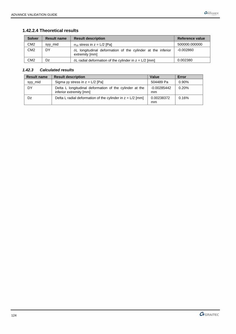
ADVANCE VALIDATION GUIDE
124
1.42.2.4 Theoretical results
Solver Result name Result description Reference value
CM2 syy_mid yy stress in z = L/2 [Pa] 500000.000000
CM2 DY L longitudinal deformation of the cylinder at the inferior extremity [mm]
-0.002860
CM2 Dz L radial deformation of the cylinder in z = L/2 [mm] 0.002380
1.42.3 Calculated results
Result name Result description Value Error
syy_mid Sigma yy stress in z = L/2 [Pa] 504489 Pa 0.90%
DY Delta L longitudinal deformation of the cylinder at the inferior extremity [mm]
-0.00285442 mm
0.20%
Dz Delta L radial deformation of the cylinder in z = L/2 [mm] 0.00238372 mm
0.16%

ADVANCE VALIDATION GUIDE
125
1.43 Thin cylinder under its self weight (01-0044SSLSB_MEF)
Test ID: 2475
Test status: Passed
1.43.1 Description
Verifies the stress, the longitudinal deformation and the radial deformation of a thin cylinder subjected to its self weight only.
1.43.2 Background
1.43.2.1 Model description
■ Reference: Structure Calculation Software Validation Guide, test SSLS 09/89;
■ Analysis type: static, linear elastic;
■ Element type: planar.
A cylinder of R radius and L length subject of self weight only.
Thin cylinder under its self weight Scale = 1/24
01-0044SSLSB_FEM
Units
I. S.
Geometry
■ Thickness: h = 0.02 m,
■ Length: L = 4 m,
■ Radius: R = 1 m.
Materials properties
■ Longitudinal elastic modulus: E = 2.1 x 10¹¹ Pa,
■ Poisson's ratio: = 0.3,
■ Density: = 7.85 x 10⁴ N/m3.

ADVANCE VALIDATION GUIDE
126
Boundary conditions
■ Outer:
► Null axial displacement at z = 0,
► For the modeling, we consider only a quarter of the cylinder, so we impose the symmetry conditions on the nodes that are parallel with the cylinder’s axis.
■ Inner: None.
Loading
■ External: Cylinder self weight,
■ Internal: None.
1.43.2.2 Stresses
Reference solution
x axis of the local coordinate system of planar elements is parallel to the cylinders axis.
xx = z
yy = 0
Finite elements modeling
■ Planar element: shell, imposed mesh,
■ 697 nodes,
■ 640 surface quadrangles.
1.43.2.3 Cylinder deformation
Reference solution
■ L longitudinal deformation of the cylinder:
L = z2
2E
■ R radial deformation of the cylinder:
R = -Rz
E
1.43.2.4 Theoretical results
Solver Result name Result description Reference value
CM2 sxx_mid xx stress for z = L [Pa] -314000.000000
CM2 DY L longitudinal deformation for z = L [mm] 0.002990
CM2 Dz R radial deformation for z = L[mm] -0.000440
* To obtain this result, you must generate a calculation note “Planar elements stresses by load case in neutral fiber" with results on center.
1.43.3 Calculated results
Result name Result description Value Error
sxx_mid Sigma xx stress for z = L [Pa] -309143 Pa 1.55%
DY Delta L longitudinal deformation for z = L [mm] 0.00298922 mm
-0.03%
Dz Delta R radial deformation for z = L [mm] -0.000443587 mm
-0.82%

ADVANCE VALIDATION GUIDE
127
1.44 Torus with uniform internal pressure (01-0045SSLSB_FEM)
Test ID: 2476
Test status: Passed
1.44.1 Description
Verifies the stress and the radial deformation of a torus with uniform internal pressure.
1.44.2 Background
1.44.2.1 Model description
■ Reference: Structure Calculation Software Validation Guide, test SSLS 10/89;
■ Analysis type: static, linear elastic;
■ Element type: planar.
Torus with uniform internal pressure
01-0045SSLSB_FEM
Units
I. S.
Geometry
■ Thickness: h = 0.02 m,
■ Transverse section radius: b = 1 m,
■ Average radius of curvature: a = 2 m.
Materials properties
■ Longitudinal elastic modulus: E = 2.1 x 10¹¹ Pa,
■ Poisson's ratio: = 0.3.
Boundary conditions
■ Outer: For the modeling, only 1/8 of the cylinder is considered, so the symmetry conditions are imposed to end nodes.

ADVANCE VALIDATION GUIDE
128
■ Inner: None.
Loading
■ External: Uniform internal pressure p = 10000 Pa
■ Internal: None.
1.44.2.2 Stresses
Reference solution
(See stresses description on the first scheme of the overview)
If a – b r a + b
11 = pb2h
r + a
r
22 = pb2h
Finite elements modeling
■ Planar element: shell, imposed mesh,
■ 361 nodes,
■ 324 surface quadrangles.
1.44.2.3 Cylinder deformation
Reference solution
■ R radial deformation of the torus:
R = pb
2Eh (r - (r + a))
Finite elements modeling
■ Planar element: shell, imposed mesh,
■ 361 nodes,
■ 324 surface quadrangles.
1.44.2.4 Theoretical results
Solver Result name Result description Reference value
CM2 syy_mid 11 stresses for r = a - b [Pa] 7.5 x 10⁵
CM2 syy_mid 11 stresses for r = a + b [Pa] 4.17 x 10⁵
CM2 sxx_mid 22 stress for all r [Pa] 2.50 x 10⁵
CM2 Dz L radial deformations of the torus for r = a - b [m] 1.19 x 10⁻⁷
CM2 Dz L radial deformations of the torus for r = a + b [m] 1.79 x 10⁻⁶
1.44.3 Calculated results
Result name Result description Value Error
syy_mid Sigma 11 stresses for r = a - b [Pa] 742770 Pa -0.96%
syy_mid Sigma 11 stresses for r = a + b [Pa] 415404 Pa -0.38%
sxx_mid Sigma 22 stress for all r [Pa] 250331 Pa 0.13%
Dz Delta L radial deformations of the torus for r = a - b [mm]
-0.000117352 mm
1.38%
Dz Delta L radial deformations of the torus for r = a + b [mm]
0.00180274 mm 0.71%

ADVANCE VALIDATION GUIDE
129
1.45 Spherical shell under internal pressure (01-0046SSLSB_FEM)
Test ID: 2477
Test status: Passed
1.45.1 Description
A spherical shell is subjected to a uniform internal pressure. The stress and the radial deformation are verified.
1.45.2 Background
1.45.2.1 Model description
■ Reference: Structure Calculation Software Validation Guide, test SSLS 14/89;
■ Analysis type: static, linear elastic;
■ Element type: planar.
Spherical shell under internal pressure
01-0046SSLSB_FEM
Units
I. S.
Geometry
■ Thickness: h = 0.02 m,
■ Radius: R2 = 1 m,
■ = 90° (hemisphere).

ADVANCE VALIDATION GUIDE
130
Materials properties
■ Longitudinal elastic modulus: E = 2.1 x 10¹¹ Pa,
■ Poisson's ratio: = 0.3.
Boundary conditions
■ Outer:
Simple support (null displacement along vertical displacement) on the shell perimeter.
For modeling, we consider only half of the hemisphere, so we impose symmetry conditions (DOF restrains placed in the vertical plane xy in translation along z and in rotation along x and y). In addition, the node at the top of the shell is restrained in translation along x to assure the stability of the structure during calculation).
■ Inner: None.
Loading
■ External: Uniform internal pressure p = 10000 Pa
■ Internal: None.
1.45.2.2 Stresses
Reference solution
(See stresses description on the first scheme of the overview)
If 0° 90°
11 = 22 = pR2
2
2h
Finite elements modeling
■ Planar element: shell, imposed mesh,
■ 343 nodes,
■ 324 planar elements.
1.45.2.3 Cylinder deformation
Reference solution
■ R radial deformation of the calotte:
R = pR22 (1 - ) sin
2Eh
Finite elements modeling
■ Planar element: shell, imposed mesh,
■ 343 nodes,
■ 324 planar elements.

ADVANCE VALIDATION GUIDE
131
Deformed shape
Spherical shell under internal pressure Scale = 1/11
Deformed
1.45.2.4 Theoretical results
Solver Result name Result description Reference value
CM2 sxx_mid 11 stress for all [Pa] 2.50 x 10⁵
CM2 syy_mid 22 stress for all [Pa] 2.50 x 10⁵
CM2 Dz R radial deformations for = 90° [m] 8.33 x 10⁻⁷
1.45.3 Calculated results
Result name Result description Value Error
sxx_mid Sigma 11 stress for all Theta [Pa] 250202 Pa 0.08%
syy_mid Sigma 22 stress for all Theta [Pa] 249907 Pa -0.04%
Dz Delta R radial deformations for Theta = 90° [mm] 0.000832794 mm
-0.02%

ADVANCE VALIDATION GUIDE
132
1.46 Pinch cylindrical shell (01-0048SSLSB_FEM)
Test ID: 2478
Test status: Passed
1.46.1 Description
A cylinder of length L is pinched by 2 diametrically opposite forces (F). The vertical displacement is verified.
1.46.2 Background
■ Reference: Structure Calculation Software Validation Guide, test SSLS 20/89;
■ Analysis type: static, linear elastic;
■ Element type: planar.
1.46.2.1 Model description
A cylinder of length L is pinched by 2 diametrically opposite forces (F).
Pinch cylindrical shell
01-0048SSLSB_FEM
Units
I. S.
Geometry
■ Length: L = 10.35 m (total length),
■ Radius: R = 4.953 m,
■ Thickness: h = 0.094 m.
ADVANCE VALIDATION GUIDE
133
Materials properties
■ Longitudinal elastic modulus: E = 10.5 x 10⁶ Pa,
■ Poisson's ratio: = 0.3125.
Boundary conditions
■ Outer: For the modeling, we consider only half of the cylinder, so we impose symmetry conditions (nodes in the horizontal xz plane are restrained in translation along y and in rotation along x and z),
■ Inner: None.
Loading
■ External: 2 punctual loads F = 100 N,
■ Internal: None.
1.46.2.2 Vertical displacement at point A
Reference solution
The reference solution is determined by averaging the results of several calculation software with implemented finite elements method. 2% uncertainty about the reference solution.
Finite elements modeling
■ Planar element: shell, imposed mesh,
■ 777 nodes,
■ 720 surface quadrangles.
1.46.2.3 Theoretical result
Solver Result name Result description Reference value
CM2 DZ Vertical displacement in point A [m] -113.9 x 10⁻³
1.46.3 Calculated results
Result name Result description Value Error
DZ Vertical displacement in point A [mm] -113.301 mm 0.53%

ADVANCE VALIDATION GUIDE
134
1.47 Spherical shell with holes (01-0049SSLSB_FEM)
Test ID: 2479
Test status: Passed
1.47.1 Description
A spherical shell with holes is subjected to 4 forces, opposite 2 by 2. The horizontal displacement is verified.
1.47.2 Background
■ Reference: Structure Calculation Software Validation Guide, test SSLS 21/89;
■ Analysis type: static, linear elastic;
■ Element type: planar.
1.47.2.1 Model description
Spherical shell with holes
01-0049SSLSB_FEM
Units
I. S.
Geometry
■ Radius: R = 10 m
■ Thickness: h = 0.04 m,
■ Opening angle of the hole: 0 = 18°.
Materials properties
■ Longitudinal elastic modulus: E = 6.285 x 10⁷ Pa,
■ Poisson's ratio: = 0.3.

ADVANCE VALIDATION GUIDE
135
Boundary conditions
■ Outer: For modeling, we consider only a quarter of the shell, so we impose symmetry conditions (nodes in the vertical yz plane are restrained in translation along x and in rotation along y and z. Nodes on the vertical xy plane are restrained in translation along z and in rotation along x and y),
■ Inner: None.
Loading
■ External: Punctual loads F = 1 N, according to the diagram,
■ Internal: None.
1.47.2.2 Horizontal displacement at point A
Reference solution
The reference solution is determined by averaging the results of several calculation software with implemented finite elements method. 2% uncertainty about the reference solution.
Finite elements modeling
■ Planar element: shell, imposed mesh,
■ 99 nodes,
■ 80 surface quadrangles.
Deformed shape
Spherical shell with holes Scale = 1/79
Deformed
1.47.2.3 Theoretical background
Solver Result name Result description Reference value
CM2 DX Horizontal displacement at point A(R,0,0) [mm] 94.0
1.47.3 Calculated results
Result name Result description Value Error
DX Horizontal displacement at point A(R,0,0) [mm] 92.6751 mm -1.41%

ADVANCE VALIDATION GUIDE
136
1.48 Spherical dome under a uniform external pressure (01-0050SSLSB_FEM)
Test ID: 2480
Test status: Passed
1.48.1 Description
A spherical dome of radius (a) is subjected to a uniform external pressure. The horizontal displacement and the external meridian stresses are verified.
1.48.2 Background
1.48.2.1 Model description
■ Reference: Structure Calculation Software Validation Guide, test SSLS 22/89;
■ Analysis type: static, linear elastic;
■ Element type: planar.
Spherical dome under a uniform external pressure
01-0050SSLSB_FEM
Units
I. S.
Geometry
■ Radius: a = 2.54 m,
■ Thickness: h = 0.0127 m,
■ Angle: = 75°.
Materials properties
■ Longitudinal elastic modulus: E = 6.897 x 10¹⁰ Pa,
■ Poisson's ratio: = 0.2.

ADVANCE VALIDATION GUIDE
137
Boundary conditions
■ Outer: Fixed on the dome perimeter,
■ Inner: None.
Loading
■ External: Uniform pressure p = 0.6897 x 10⁶ Pa,
■ Internal: None.
1.48.2.2 Horizontal displacement and exterior meridian stress
Reference solution
The reference solution is determined by averaging the results of several calculation software with implemented finite elements method. 2% uncertainty about the reference solution.
Finite elements modeling
■ Planar element: shell, imposed mesh,
■ 401 nodes,
■ 400 planar elements.
Deformed shape
1.48.2.3 Theoretical results
Solver Result name Result description Reference value
CM2 DX Horizontal displacements in = 15° 1.73 x 10⁻³
CM2 DX Horizontal displacements in = 45° -1.02 x 10⁻³
CM2 syy_mid yy external meridian stresses in = 15° -74
CM2 sxx_mid XX external meridian stresses in = 45° -68
1.48.3 Calculated results
Result name Result description Value Error
DX Horizontal displacements in Psi = 15° [mm] 1.73064 mm 0.04%
DX Horizontal displacements in Psi = 45° [mm] -1.01367 mm 0.62%
syy_mid Sigma yy external meridian stresses in Psi = 15° [MPa]
-72.2609 MPa
2.35%
sxx_mid Sigma XX external meridian stresses in Psi = 45° [MPa]
-68.9909 MPa
-1.46%

ADVANCE VALIDATION GUIDE
138
1.49 Simply supported square plate under a uniform load (01-0051SSLSB_FEM)
Test ID: 2481
Test status: Passed
1.49.1 Description
A square plate simply supported is subjected to a uniform load. The vertical displacement and the bending moments at the plate center are verified.
1.49.2 Background
1.49.2.1 Model description
■ Reference: Structure Calculation Software Validation Guide, test SSLS 24/89;
■ Analysis type: static, linear elastic;
■ Element type: planar.
Simply supported square plate under a uniform load Scale = 1/9
01-0051SSLSB_FEM
Units
I. S.
Geometry
■ Side: a =b = 1 m,
■ Thickness: h = 0.01 m,
Materials properties
■ Longitudinal elastic modulus: E = 1.0 x 10⁷ Pa,
■ Poisson's ratio: = 0.3.
Boundary conditions
■ Outer: Simple support on the plate perimeter (null displacement along z-axis),
■ Inner: None
Loading
■ External: Normal pressure of plate p = pZ = -1.0 Pa,
■ Internal: None.

ADVANCE VALIDATION GUIDE
139
1.49.2.2 Vertical displacement and bending moment at the center of the plate
Reference solution
Love-Kirchhoff thin plates theory.
Finite elements modeling
■ Planar element: plate, imposed mesh,
■ 361 nodes,
■ 324 planar elements.
1.49.2.3 Theoretical result
Solver Result name Result description Reference value
CM2 DZ Vertical displacement at plate center [m] -4.43 x 10⁻³
CM2 Mxx MX bending moment at plate center [Nm] 0.0479
CM2 Myy MY bending moment at plate center [Nm] 0.0479
1.49.3 Calculated results
Result name Result description Value Error
DZ Vertical displacement at plate center [m] -0.00435847 m 1.61%
Mxx Mx bending moment at plate center [Nm] 0.0471381 N*m -1.59%
Myy My bending moment at plate center [Nm] 0.0471381 N*m -1.59%

ADVANCE VALIDATION GUIDE
140
1.50 Simply supported rectangular plate under a uniform load (01-0052SSLSB_FEM)
Test ID: 2482
Test status: Passed
1.50.1 Description
A rectangular plate simply supported is subjected to a uniform load. The vertical displacement and the bending moments at the plate center are verified.
1.50.2 Background
1.50.2.1 Model description
■ Reference: Structure Calculation Software Validation Guide, test SSLS 24/89;
■ Analysis type: static, linear elastic;
■ Element type: planar.
Simply supported rectangular plate under a uniform load Scale = 1/11
01-0052SSLSB_FEM
Units
I. S.
Geometry
■ Width: a = 1 m,
■ Length: b = 2 m,
■ Thickness: h = 0.01 m,
Materials properties
■ Longitudinal elastic modulus: E = 1.0 x 10⁷ Pa,
■ Poisson's ratio: = 0.3.
Boundary conditions
■ Outer: Simple support on the plate perimeter (null displacement along z-axis),
■ Inner: None.
Loading
■ External: Normal pressure of plate p = pZ = -1.0 Pa,
■ Internal: None.

ADVANCE VALIDATION GUIDE
141
1.50.2.2 Vertical displacement and bending moment at the center of the plate
Reference solution
Love-Kirchhoff thin plates theory.
Finite elements modeling
■ Planar element: plate, imposed mesh,
■ 435 nodes,
■ 392 surface quadrangles.
1.50.2.3 Theoretical background
Solver Result name Result description Reference value
CM2 DZ Vertical displacement at plate center [m] -1.1060 x 10⁻²
CM2 Mxx MX bending moment at plate center [Nm] -0.1017
CM2 Myy MY bending moment at plate center [Nm] -0.0464
1.50.3 Calculated results
Result name Result description Value Error
DZ Vertical displacement at plate center [cm] -1.10238 cm 0.33%
Mxx Mx bending moment at plate center [Nm] -0.101737 N*m -0.04%
Myy My bending moment at plate center [Nm] -0.0462457 N*m
0.33%

ADVANCE VALIDATION GUIDE
142
1.51 Simply supported rectangular plate under a uniform load (01-0053SSLSB_FEM)
Test ID: 2483
Test status: Passed
1.51.1 Description
A rectangular plate simply supported is subjected to a uniform load. The vertical displacement and the bending moments at the plate center are verified.
1.51.2 Background
1.51.2.1 Model description
■ Reference: Structure Calculation Software Validation Guide, test SSLS 24/89;
■ Analysis type: static, linear elastic;
■ Element type: planar.
Simply supported rectangular plate under a uniform load Scale = 1/25
01-0053SSLSB_FEM
Units
I. S.
Geometry
■ Width: a = 1 m,
■ Length: b = 5 m,
■ Thickness: h = 0.01 m,
Materials properties
■ Longitudinal elastic modulus: E = 1.0 x 10⁷ Pa,
■ Poisson's ratio: = 0.3.
Boundary conditions
■ Outer: Simple support on the plate perimeter (null displacement along z-axis),
■ Inner: None.

ADVANCE VALIDATION GUIDE
143
Loading
■ External: Normal pressure of plate p = pZ = -1.0 Pa,
■ Internal: None.
1.51.2.2 Vertical displacement and bending moment at the center of the plate
Reference solution
Love-Kirchhoff thin plates theory.
Finite elements modeling
■ Planar element: plate, imposed mesh,
■ 793 nodes,
■ 720 surface quadrangles.
1.51.2.3 Theoretical results
Solver Result name Result description Reference value
CM2 DZ Vertical displacement at plate center [m] 1.416 x 10⁻²
CM2 Mxx MX bending moment at plate center [Nm] 0.1246
CM2 Myy MY bending moment at plate center [Nm] 0.0375
1.51.3 Calculated results
Result name Result description Value Error
DZ Vertical displacement at plate center [cm] -1.40141 cm 1.03%
Mxx Mx bending moment at plate center [Nm] -0.124082 N*m 0.42%
Myy My bending moment at plate center [Nm] -0.0375624 N*m -0.17%

ADVANCE VALIDATION GUIDE
144
1.52 Simply supported rectangular plate loaded with punctual force and moments (01-0054SSLSB_FEM)
Test ID: 2484
Test status: Passed
1.52.1 Description
A rectangular plate simply supported is subjected to a punctual force and moments. The vertical displacement is verified.
1.52.2 Background
1.52.2.1 Model description
■ Reference: Structure Calculation Software Validation Guide, test SSLS 26/89;
■ Analysis type: static linear;
■ Element type: planar.
Simply supported rectangular plate loaded with punctual force and moments
01-0054SSLSB_FEM
Units
I. S.
Geometry
■ Width: DA = CB = 20 m,
■ Length: AB = DC = 5 m,
■ Thickness: h = 1 m,
Materials properties
■ Longitudinal elastic modulus: E =1000 Pa,
■ Poisson's ratio: = 0.3.
Boundary conditions
■ Outer: Punctual support at A, B and D (null displacement along z-axis),
■ Inner: None.

ADVANCE VALIDATION GUIDE
145
Loading
■ External:
► In A: MX = 20 Nm, MY = -10 Nm,
► In B: MX = 20 Nm, MY = 10 Nm,
► In C: FZ = -2 N, MX = -20 Nm, MY = 10 Nm,
► In D: MX = -20 Nm, MY = -10 Nm,
■ Internal: None.
1.52.2.2 Vertical displacement at C
Reference solution
Love-Kirchhoff thin plates theory.
Finite elements modeling
■ Planar element: plate, imposed mesh,
■ 867 nodes,
■ 800 surface quadrangles.
Deformed shape
Simply supported rectangular plate loaded with punctual force and moments
Deformed
1.52.2.3 Theoretical results
Solver Result name Result description Reference value
CM2 Dz Vertical displacement in point C [m] -12.480
1.52.3 Calculated results
Result name Result description Value Error
Dz Vertical displacement in point C [m] -12.6677 m -1.50%

ADVANCE VALIDATION GUIDE
146
1.53 Shear plate perpendicular to the medium surface (01-0055SSLSB_FEM)
Test ID: 2485
Test status: Passed
1.53.1 Description
Verifies the vertical displacement of a rectangular shear plate fixed at one end, loaded with two forces.
1.53.2 Background
1.53.2.1 Model description
■ Reference: Structure Calculation Software Validation Guide, test SSLS 27/89;
■ Analysis type: static;
■ Element type: planar.
Shear plate Scale = 1/50
01-0055SSLSB_FEM
Units
I. S.
Geometry
■ Length: L = 12 m,
■ Width: l = 1 m,
■ Thickness: h = 0.05 m,
Materials properties
■ Longitudinal elastic modulus: E = 1.0 x 10⁷ Pa,
■ Poisson's ratio: = 0.25.
Boundary conditions
■ Outer: Fixed AD edge,
■ Inner: None.

ADVANCE VALIDATION GUIDE
147
Loading
■ External:
► At B: Fz = -1.0 N,
► At C: FZ = 1.0 N,
■ Internal: None.
1.53.2.2 Vertical displacement at C
Reference solution
Analytical solution.
Finite elements modeling
■ Planar element: plate, imposed mesh,
■ 497 nodes,
■ 420 surface quadrangles.
Deformed shape
Shear plate Scale = 1/35
Deformed
1.53.2.3 Theoretical results
Solver Result name Result description Reference value
CM2 Dz Vertical displacement in point C [m] 35.37 x 10⁻³
1.53.3 Calculated results
Result name Result description Value Error
Dz Vertical displacement in point C [m] 35.6655 mm 0.84%

ADVANCE VALIDATION GUIDE
148
1.54 Triangulated system with hinged bars (01-0056SSLLB_FEM)
Test ID: 2486
Test status: Passed
1.54.1 Description
A truss with hinged bars is placed on three punctual supports (subjected to imposed displacements) and is loaded with two punctual forces. A thermal load is applied to all the bars. The traction force and the vertical displacement are verified.
1.54.2 Background
1.54.2.1 Model description
■ Reference: Structure Calculation Software Validation Guide, test SSLL 12/89;
■ Analysis type: static (plane problem);
■ Element type: linear.
Units
I. S.
Geometry
■ = 30°,
■ Section A1 = 1.41 x 10⁻³ m2,
■ Section A2 = 2.82 x 10⁻³ m2.
Materials properties
■ Longitudinal elastic modulus: E =2.1 x 10¹¹ Pa,
■ Coefficient of linear expansion: = 10-5 °C-1.
Boundary conditions
■ Outer:
► Hinge at A (uA = vA = 0),
► Roller supports at B and C ( uB = v’C = 0),
■ Inner: None.
Loading
■ External:
► Support displacement: vA = -0.02 m ; vB = -0.03 m ; v’C = -0.015 m ,
► Punctual loads: FE = -150 KN ; FF = -100 KN,

ADVANCE VALIDATION GUIDE
149
► Expansion effect on all bars for a temperature variation of 150° in relation with the assembly temperature (specified geometry),
■ Internal: None.
1.54.2.2 Tension force in BD bar
Reference solution
Determining the hyperstatic unknown with the section cut method.
Finite elements modeling
■ Linear element: S beam, automatic mesh,
■ 11 nodes,
■ 17 S beams + 1 rigid S beam for the modeling of the simple support at C.
1.54.2.3 Vertical displacement at D
Reference solution
vD displacement was determined by several software with implemented finite elements method.
Finite elements modeling
■ Linear element: S beam, automatic mesh,
■ 11 nodes,
■ 17 S beams + 1 rigid S beam for the modeling of simple support at C.
Deformed shape
Triangulated system with hinged bars
01-0056SSLLB_FEM
1.54.2.4 Theoretical results
Solver Result name Result description Reference value
CM2 Fx FX traction force on BD bar [N] 43633
CM2 DZ Vertical displacement on point D [m] -0.01618
1.54.3 Calculated results
Result name Result description Value Error
Fx Fx traction force on BD bar [N] 42892.3 N -1.70%
DZ Vertical displacement on point D [m] -0.016236 m -0.35%

ADVANCE VALIDATION GUIDE
150
1.55 A plate (0.01 m thick), fixed on its perimeter, loaded with a uniform pressure (01-0057SSLSB_FEM)
Test ID: 2487
Test status: Passed
1.55.1 Description
Verifies the vertical displacement for a square plate (0.01 m thick), of side "a", fixed on its perimeter, loaded with a uniform pressure.
1.55.2 Background
1.55.2.1 Model description
■ Reference: Structure Calculation Software Validation Guide, test SSLV 09/89;
■ Analysis type: static;
■ Element type: planar.
Units
I. S.
Geometry
■ Side: a = 1 m,
■ Thickness: h = 0.01 m,
■ Slenderness: = ah = 100.
Materials properties
■ Reinforcement,
■ Longitudinal elastic modulus: E = 2.1 x 10¹¹ Pa,
■ Poisson's ratio: = 0.3.
Boundary conditions
■ Outer:
Fixed sides: AB and BD,
For the modeling, we impose symmetry conditions at the CB side (restrained displacement along x and restrained rotation around y and z) and CD side (restrained displacement along y and restrained rotation around x and z),
■ Inner: None.
Loading
■ External: 1 MPa uniform pressure,
■ Internal: None.

ADVANCE VALIDATION GUIDE
151
1.55.2.2 Vertical displacement at C
Reference solution
This problem has a precise analytical solution only for thin plates. Therefore we propose the solutions obtained with Serendip elements with 20 nodes or thick plate elements of 4 nodes. The expected result should be between these
values at 5%.
Finite elements modeling
■ Planar element: plate, imposed mesh,
■ 289 nodes,
■ 256 surface quadrangles.
1.55.2.3 Theoretical results
Solver Result name Result description Reference value
CM2 Dz Vertical displacement in point C [m] -6.639 x 10⁻²
1.55.3 Calculated results
Result name Result description Value Error
Dz Vertical displacement in point C [cm] -6.56563 cm 1.11%

ADVANCE VALIDATION GUIDE
152
1.56 A plate (0.01333 m thick), fixed on its perimeter, loaded with a uniform pressure (01-0058SSLSB_FEM)
Test ID: 2488
Test status: Passed
1.56.1 Description
Verifies the vertical displacement for a square plate (0.01333 m thick), of side "a", fixed on its perimeter, loaded with a uniform pressure.
1.56.2 Background
1.56.2.1 Model description
■ Reference: Structure Calculation Software Validation Guide, test SSLV 09/89;
■ Analysis type: static;
■ Element type: planar.
Square plate of side "a", for the modeling, only a quarter of the plate is considered.
Units
I. S.
Geometry
■ Side: a = 1 m,
■ Thickness: h = 0.01333 m,
■ Slenderness: = ah = 75.
Materials properties
■ Reinforcement,
■ Longitudinal elastic modulus: E = 2.1 x 10¹¹ Pa,
■ Poisson's ratio: = 0.3.
Boundary conditions
■ Outer:
Fixed sides: AB and BD,
For the modeling, we impose symmetry conditions at the CB side (restrained displacement along x and restrained rotation around y and z) and CD side (restrained displacement along y and restrained rotation around x and z),
■ Inner: None.
Loading
■ External: 1 MPa uniform pressure,

ADVANCE VALIDATION GUIDE
153
■ Internal: None.
1.56.2.2 Vertical displacement at C
Reference solution
This problem has a precise analytical solution only for thin plates. Therefore we propose the solutions obtained with Serendip elements with 20 nodes or thick plate elements of 4 nodes. The expected result should be between these values at ± 5%.
Finite elements modeling
■ Planar element: plate, imposed mesh,
■ 289 nodes,
■ 256 surface quadrangles.
1.56.2.3 Theoretical results
Solver Result name Result description Reference value
CM2 Dz Vertical displacement in point C [m] -2.8053 x 10⁻²
1.56.3 Calculated results
Result name Result description Value Error
Dz Vertical displacement in point C [cm] -2.79502 cm 0.37%

ADVANCE VALIDATION GUIDE
154
1.57 A plate (0.02 m thick), fixed on its perimeter, loaded with a uniform pressure (01-0059SSLSB_FEM)
Test ID: 2489
Test status: Passed
1.57.1 Description
Verifies the vertical displacement for a square plate (0.02 m thick), of side "a", fixed on its perimeter, loaded with a uniform pressure.
1.57.2 Background
1.57.2.1 Model description
■ Reference: Structure Calculation Software Validation Guide, test SSLV 09/89;
■ Analysis type: static;
■ Element type: planar.
Units
I. S.
Geometry
■ Side: a = 1 m,
■ Thickness: h = 0.02 m,
■ Slenderness: = ah = 50.
Materials properties
■ Reinforcement,
■ Longitudinal elastic modulus: E = 2.1 x 10¹¹ Pa,
■ Poisson's ratio: = 0.3.
Boundary conditions
■ Outer:
Fixed edges: AB and BD,
For the modeling, we impose symmetry conditions at the CB side (restrained displacement along x and restrained rotation around y and z) and CD side (restrained displacement along y and restrained rotation around x and z),
■ Inner: None.
Loading
■ External: 1 MPa uniform pressure,
■ Internal: None.

ADVANCE VALIDATION GUIDE
155
1.57.2.2 Vertical displacement at C
Reference solution
This problem has a precise analytical solution only for thin plates. Therefore we propose the solutions obtained with Serendip elements with 20 nodes or thick plate elements of 4 nodes. The expected result should be between these values at ± 5%.
Finite elements modeling
■ Planar element: plate, imposed mesh,
■ 289 nodes,
■ 256 surface quadrangles.
1.57.2.3 Theoretical results
Solver Result name Result description Reference value
CM2 Dz Vertical displacement in point C [m] -0.83480 x 10⁻²
1.57.3 Calculated results
Result name Result description Value Error
Dz Vertical displacement in point C [cm] -0.82559 cm 1.10%

ADVANCE VALIDATION GUIDE
156
1.58 A plate (0.05 m thick), fixed on its perimeter, loaded with a uniform pressure (01-0060SSLSB_FEM)
Test ID: 2490
Test status: Passed
1.58.1 Description
Verifies the vertical displacement for a square plate (0.05 m thick), of side "a", fixed on its perimeter, loaded with a uniform pressure.
1.58.2 Background
1.58.2.1 Model description
■ Reference: Structure Calculation Software Validation Guide, test SSLV 09/89;
■ Analysis type: static;
■ Element type: planar.
Units
I. S.
Geometry
■ Side: a = 1 m,
■ Thickness: h = 0.05 m,
■ Slenderness: = ah = 20.
Materials properties
■ Reinforcement,
■ Longitudinal elastic modulus: E = 2.1 x 10¹¹ Pa,
■ Poisson's ratio: = 0.3.
Boundary conditions
■ Outer:
Fixed edges: AB and BD,
For the modeling, we impose symmetry conditions at the CB side (restrained displacement along x and restrained rotation around y and z) and CD side (restrained displacement along y and restrained rotation around x and z),
■ Inner: None.
Loading
■ External: 1 MPa uniform pressure,
■ Internal: None.

ADVANCE VALIDATION GUIDE
157
1.58.2.2 Vertical displacement at C
Reference solution
This problem has a precise analytical solution only for thin plates. Therefore we propose the solutions obtained with Serendip elements with 20 nodes or thick plate elements of 4 nodes. The expected result should be between these values at ± 5%.
Finite elements modeling
■ Planar element: plate, imposed mesh,
■ 289 nodes,
■ 256 surface quadrangles.
1.58.2.3 Theoretical results
Solver Result name Result description Reference value
CM2 Dz Vertical displacement in point C [m] -0.55474 x 10⁻³
1.58.3 Calculated results
Result name Result description Value Error
Dz Vertical displacement in point C [cm] -0.0549874 cm
0.88%

ADVANCE VALIDATION GUIDE
158
1.59 A plate (0.1 m thick), fixed on its perimeter, loaded with a uniform pressure (01-0061SSLSB_FEM)
Test ID: 2491
Test status: Passed
1.59.1 Description
Verifies the vertical displacement for a square plate (0.1 m thick), of side "a", fixed on its perimeter, loaded with a uniform pressure.
1.59.2 Background
1.59.2.1 Model description
■ Reference: Structure Calculation Software Validation Guide, test SSLV 09/89;
■ Analysis type: static;
■ Element type: planar.
Units
I. S.
Geometry
■ Side: a = 1 m,
■ Thickness: h = 0.1 m,
■ Slenderness: = ah = 10.
Materials properties
■ Reinforcement,
■ Longitudinal elastic modulus: E = 2.1 x 10¹¹ Pa,
■ Poisson's ratio: = 0.3.
Boundary conditions
■ Outer:
Fixed edges: AB and BD,
For the modeling, we impose symmetry conditions at the CB side (restrained displacement along x and restrained rotation around y and z) and CD side (restrained displacement along y and restrained rotation around x and z),
■ Inner: None.
Loading
■ External: 1 MPa uniform pressure,
■ Internal: None.

ADVANCE VALIDATION GUIDE
159
1.59.2.2 Vertical displacement at C
Reference solution
This problem has a precise analytical solution only for thin plates. Therefore we propose the solutions obtained with Serendip elements with 20 nodes or thick plate elements of 4 nodes. The expected result should be between these values at ± 5%.
Finite elements modeling
■ Planar element: plate, imposed mesh,
■ 289 nodes,
■ 256 surface quadrangles.
1.59.2.3 Theoretical results
Solver Result name Result description Reference value
CM2 Dz Vertical displacement in point C [m] -0.78661 x 10⁻⁴
1.59.3 Calculated results
Result name Result description Value Error
Dz Vertical displacement in point C [mm] -0.0781846 mm
0.61%

ADVANCE VALIDATION GUIDE
160
1.60 A plate (0.01 m thick), fixed on its perimeter, loaded with a punctual force (01-0062SSLSB_FEM)
Test ID: 2492
Test status: Passed
1.60.1 Description
Verifies the vertical displacement for a square plate (0.01 m thick), of side "a", fixed on its perimeter, loaded with a punctual force in the center.
1.60.2 Background
1.60.2.1 Model description
■ Reference: Structure Calculation Software Validation Guide, test SSLV 09/89;
■ Analysis type: static;
■ Element type: planar.
Square plate of side "a".
0.01 m thick plate fixed on its perimeter Scale = 1/5
01-0062SSLSB_FEM
Units
I. S.
Geometry
■ Side: a = 1 m,
■ Thickness: h = 0.01 m,
■ Slenderness: = ah = 100.
Materials properties
■ Reinforcement,
■ Longitudinal elastic modulus: E = 2.1 x 10¹¹ Pa,
■ Poisson's ratio: = 0.3.
Boundary conditions
■ Outer: Fixed edges,
■ Inner: None.

ADVANCE VALIDATION GUIDE
161
Loading
■ External: Punctual force applied on the center of the plate: FZ = -106 N,
■ Internal: None.
1.60.2.2 Vertical displacement at point C (center of the plate)
Reference solution
This problem has a precise analytical solution only for thin plates. Therefore we propose the solutions obtained with Serendip elements with 20 nodes or thick plate elements of 4 nodes. The expected result should be between these values at ± 5%.
Finite elements modeling
■ Planar element: plate, imposed mesh,
■ 961 nodes,
■ 900 surface quadrangles.
1.60.2.3 Theoretical results
Solver Result name Result description Reference value
CM2 DZ Vertical displacement in point C [m] -0.29579
1.60.3 Calculated results
Result name Result description Value Error
DZ Vertical displacement in point C [m] -0.292146 m 1.23%

ADVANCE VALIDATION GUIDE
162
1.61 A plate (0.01333 m thick), fixed on its perimeter, loaded with a punctual force (01-0063SSLSB_FEM)
Test ID: 2493
Test status: Passed
1.61.1 Description
Verifies the vertical displacement for a square plate (0.01333 m thick), of side "a", fixed on its perimeter, loaded with a punctual force in the center.
1.61.2 Background
1.61.2.1 Model description
■ Reference: Structure Calculation Software Validation Guide, test SSLV 09/89;
■ Analysis type: static;
■ Element type: planar.
0.01333 m thick plate fixed on its perimeter Scale = 1/5
01-0063SSLSB_FEM
Units
I. S.
Geometry
■ Side: a = 1 m,
■ Thickness: h = 0.01333 m,
■ Slenderness: = ah = 75.
Materials properties
■ Reinforcement,
■ Longitudinal elastic modulus: E = 2.1 x 10¹¹ Pa,
■ Poisson's ratio: = 0.3.
Boundary conditions
■ Outer: Fixed sides,
■ Inner: None.
Loading
■ External: Punctual force applied on the center of the plate: FZ = -106 N,

ADVANCE VALIDATION GUIDE
163
■ Internal: None.
1.61.2.2 Vertical displacement at point C (the center of the plate)
Reference solution
This problem has a precise analytical solution only for thin plates. Therefore we propose the solutions obtained with Serendip elements with 20 nodes or thick plate elements of 4 nodes. The expected result should be between these values at ± 5%.
Finite elements modeling
■ Planar element: plate, imposed mesh,
■ 961 nodes,
■ 900 surface quadrangles.
1.61.2.3 Theoretical results
Solver Result name Result description Reference value
CM2 DZ Vertical displacement in point C [m] -0.12525
1.61.3 Calculated results
Result name Result description Value Error
DZ Vertical displacement in point C [m] -0.124583 m 0.53%

ADVANCE VALIDATION GUIDE
164
1.62 A plate (0.02 m thick), fixed on its perimeter, loaded with a punctual force (01-0064SSLSB_FEM)
Test ID: 2494
Test status: Passed
1.62.1 Description
Verifies the vertical displacement for a square plate (0.02 m thick), of side "a", fixed on its perimeter, loaded with a punctual force in the center.
1.62.2 Background
1.62.2.1 Model description
■ Reference: Structure Calculation Software Validation Guide, test SSLV 09/89;
■ Analysis type: static;
■ Element type: planar.
0.02 m thick plate fixed on its perimeter Scale = 1/5
01-0064SSLSB_FEM
Units
I. S.
Geometry
■ Side: a = 1 m,
■ Thickness: h = 0.02 m,
■ Slenderness: = 50.
Materials properties
■ Reinforcement,
■ Longitudinal elastic modulus: E = 2.1 x 10¹¹ Pa,
■ Poisson's ratio: = 0.3.
Boundary conditions
■ Outer: Fixed edges,
■ Inner: None.
Loading
■ External: punctual force applied in the center of the plate: FZ = -106 N,
■ Internal: None.

ADVANCE VALIDATION GUIDE
165
1.62.2.2 Vertical displacement at point C (the center of the plate)
Reference solution
This problem has a precise analytical solution only for thin plates. Therefore we propose the solutions obtained with Serendip elements with 20 nodes or thick plate elements of 4 nodes. The expected result should be between these values at ± 5%.
Finite elements modeling
■ Planar element: plate, imposed mesh,
■ 961 nodes,
■ 900 surface quadrangles.
1.62.2.3 Theoretical results
Solver Result name Result description Reference value
CM2 DZ Vertical displacement in point C [m] -0.037454
1.62.3 Calculated results
Result name Result description Value Error
DZ Vertical displacement in point C [m] -0.0369818 m
1.26%

ADVANCE VALIDATION GUIDE
166
1.63 A plate (0.05 m thick), fixed on its perimeter, loaded with a punctual force (01-0065SSLSB_FEM)
Test ID: 2495
Test status: Passed
1.63.1 Description
Verifies the vertical displacement for a square plate (0.05 m thick), of side "a", fixed on its perimeter, loaded with a punctual force in the center.
1.63.2 Background
1.63.2.1 Model description
■ Reference: Structure Calculation Software Validation Guide, test SSLV 09/89;
■ Analysis type: static;
■ Element type: planar.
0.05 m thick plate fixed on its perimeter Scale = 1/5
01-0065SSLSB_FEM
Units
I. S.
Geometry
■ Side: a = 1 m,
■ Thickness: h = 0.05 m,
■ Slenderness: = 20.
Materials properties
■ Reinforcement,
■ Longitudinal elastic modulus: E = 2.1 x 10¹¹ Pa,
■ Poisson's ratio: = 0.3.
Boundary conditions
■ Outer: Fixed sides,
■ Inner: None.
Loading
■ External: Punctual force applied at the center of the plate: FZ = -106 N,
■ Internal: None.

ADVANCE VALIDATION GUIDE
167
1.63.2.2 Vertical displacement at point C center of the plate)
Reference solution
This problem has a precise analytical solution only for thin plates. Therefore we propose the solutions obtained with Serendip elements with 20 nodes or thick plate elements of 4 nodes. The expected result should be between these values at ± 5%.
Finite elements modeling
■ Planar element: plate, imposed mesh,
■ 961 nodes,
■ 900 surface quadrangles.
1.63.2.3 Theoretical results
Solver Result name Result description Reference value
CM2 DZ Vertical displacement in point C [m] -0.2595 x 10⁻²
1.63.3 Calculated results
Result name Result description Value Error
DZ Vertical displacement in point C [m] -0.00257232 m
0.86%

ADVANCE VALIDATION GUIDE
168
1.64 A plate (0.1 m thick), fixed on its perimeter, loaded with a punctual force (01-0066SSLSB_FEM)
Test ID: 2496
Test status: Passed
1.64.1 Description
Verifies the vertical displacement for a square plate (0.1 m thick), of side "a", fixed on its perimeter, loaded with a punctual force in the center.
1.64.2 Background
1.64.2.1 Model description
■ Reference: Structure Calculation Software Validation Guide, test SSLV 09/89;
■ Analysis type: static;
■ Element type: planar.
0.1 m thick plate fixed on its perimeter Scale = 1/5
01-0066SSLSB_FEM
Units
I. S.
Geometry
■ Side: a = 1 m,
■ Thickness: h = 0.1 m,
■ Slenderness: = 10.
Materials properties
■ Reinforcement,
■ Longitudinal elastic modulus: E = 2.1 x 10¹¹ Pa,
■ Poisson's ratio: = 0.3.
Boundary conditions
■ Outer: Fixed edges,
■ Inner: None.
Loading
■ External: punctual force applied in the center of the plate: FZ = -106 N,
■ Internal: None.

ADVANCE VALIDATION GUIDE
169
1.64.2.2 Vertical displacement at point C (center of the plate)
Reference solution
This problem has a precise analytical solution only for thin plates. Therefore we propose the solutions obtained with Serendip elements with 20 nodes or thick plate elements of 4 nodes. The expected result should be between these values at ± 5%.
Finite elements modeling
■ Planar element: plate, imposed mesh,
■ 961 nodes,
■ 900 surface quadrangles.
1.64.2.3 Theoretical results
Solver Result name Result description Reference value
CM2 DZ Vertical displacement in point C [m] -0.42995 x 10⁻³
1.64.3 Calculated results
Result name Result description Value Error
DZ Vertical displacement in point C [mm] -0.412094 mm
4.15%

ADVANCE VALIDATION GUIDE
170
1.65 Vibration mode of a thin piping elbow in space (case 1) (01-0067SDLLB_FEM)
Test ID: 2497
Test status: Passed
1.65.1 Description
Verifies the eigen mode transverse frequencies for a thin piping elbow with a radius of 1 m, fixed on its ends and subjected to its self weight only.
1.65.2 Background
1.65.2.1 Model description
■ Reference: Structure Calculation Software Validation Guide, test SDLL 14/89;
■ Analysis type: modal analysis (space problem);
■ Element type: linear.
Vibration mode of a thin piping elbow Scale = 1/7
01-0067SDLLB_FEM
Units
I. S.
Geometry
■ Average radius of curvature: OA = R = 1 m,
■ Straight circular hollow section:
■ Outer diameter: de = 0.020 m,
■ Inner diameter: di = 0.016 m,
■ Section: A = 1.131 x 10⁻⁴ m2,
■ Flexure moment of inertia relative to the y-axis: Iy = 4.637 x 10⁻⁹ m4,
■ Flexure moment of inertia relative to z-axis: Iz = 4.637 x 10⁻⁹ m4,
■ Polar inertia: Ip = 9.274 x 10⁻⁹ m4.
■ Points coordinates (in m):
► O ( 0 ; 0 ; 0 )
► A ( 0 ; R ; 0 )
► B ( R ; 0 ; 0 )
Materials properties
■ Longitudinal elastic modulus: E = 2.1 x 10¹¹ Pa,
■ Poisson's ratio: = 0.3,

ADVANCE VALIDATION GUIDE
171
■ Density: = 7800 kg/m3.
Boundary conditions
■ Outer: Fixed at points A and B,
■ Inner: None.
Loading
■ External: None,
■ Internal: None.
1.65.2.2 Eigen modes frequencies
Reference solution
The Rayleigh method applied to a thin curved beam is used to determine parameters such as:
■ transverse bending:
fj = i
2
2 R2 GIp
A where i = 1,2.
Finite elements modeling
■ Linear element: beam,
■ 11 nodes,
■ 10 linear elements.
Eigen mode shapes
1.65.2.3 Theoretical results
Solver Result name Result description Reference value
CM2 Eigen mode Eigen mode Transverse 1 frequency [Hz] 44.23
CM2 Eigen mode Eigen mode Transverse 2 frequency [Hz] 125
1.65.3 Calculated results
Result name Result description Value Error
Eigen mode Eigen mode Transverse 1 frequency [Hz] 44.12 Hz -0.25%
Eigen mode Eigen mode Transverse 2 frequency [Hz] 120.09 Hz -3.93%

ADVANCE VALIDATION GUIDE
172
1.66 Vibration mode of a thin piping elbow in space (case 2) (01-0068SDLLB_FEM)
Test ID: 2498
Test status: Passed
1.66.1 Description
Verifies the eigen mode transverse frequencies for a thin piping elbow with a radius of 1 m, extended with two straight elements (0.6 m long) and subjected to its self weight only.
1.66.2 Background
1.66.2.1 Model description
■ Reference: Structure Calculation Software Validation Guide, test SDLL 14/89;
■ Analysis type: modal analysis (in space);
■ Element type: linear.
Vibration mode of a thin piping elbow Scale = 1/11
01-0068SDLLB_FEM
Units
I. S.
Geometry
■ Average radius of curvature: OA = R = 1 m,
■ L = 0.6 m,
■ Straight circular hollow section:
■ Outer diameter: de = 0.020 m,
■ Inner diameter: di = 0.016 m,
■ Section: A = 1.131 x 10⁻⁴ m2,
■ Flexure moment of inertia relative to the y-axis: Iy = 4.637 x 10⁻⁹ m4,
■ Flexure moment of inertia relative to z-axis: Iz = 4.637 x 10⁻⁹ m4,
■ Polar inertia: Ip = 9.274 x 10⁻⁹ m4.
■ Points coordinates (in m):
► O ( 0 ; 0 ; 0 )
► A ( 0 ; R ; 0 )
► B ( R ; 0 ; 0 )
► C ( -L ; R ; 0 )
► D ( R ; -L ; 0 )
Materials properties
■ Longitudinal elastic modulus: E = 2.1 x 10¹¹ Pa,

ADVANCE VALIDATION GUIDE
173
■ Poisson's ratio: = 0.3,
■ Density: = 7800 kg/m3.
Boundary conditions
■ Outer:
► Fixed at points C and D
► In A: translation restraint along y and z,
► In B: translation restraint along x and z,
■ Inner: None.
Loading
■ External: None,
■ Internal: None.
1.66.2.2 Eigen modes frequencies
Reference solution
The Rayleigh method applied to a thin curved beam is used to determine parameters such as:
■ transverse bending:
fj = i
2
2 R2 GIp
A where i = 1,2.
Finite elements modeling
■ Linear element: beam,
■ 23 nodes,
■ 22 linear elements.
Eigen mode shapes
1.66.2.3 Theoretical results
Solver Result name Result description Reference value
CM2 Eigen mode Eigen mode Transverse 1 frequency [Hz] 33.4
CM2 Eigen mode Eigen mode Transverse 2 frequency [Hz] 100
1.66.3 Calculated results
Result name Result description Value Error
Eigen mode Eigen mode Transverse 1 frequency [Hz] 33.19 Hz -0.63%
Eigen mode Eigen mode Transverse 2 frequency [Hz] 94.62 Hz -5.38%

ADVANCE VALIDATION GUIDE
174
1.67 Vibration mode of a thin piping elbow in space (case 3) (01-0069SDLLB_FEM)
Test ID: 2499
Test status: Passed
1.67.1 Description
Verifies the eigen mode transverse frequencies for a thin piping elbow with a radius of 1 m, extended with two straight elements (2 m long) and subjected to its self weight only.
1.67.2 Background
1.67.2.1 Model description
■ Reference: Structure Calculation Software Validation Guide, test SDLL 14/89;
■ Analysis type: modal analysis (space problem);
■ Element type: linear.
Vibration mode of a thin piping elbow Scale = 1/12
01-0069SDLLB_FEM
Units
I. S.
Geometry
■ Average radius of curvature: OA = R = 1 m,
■ L = 2 m,
■ Straight circular hollow section:
■ Outer diameter: de = 0.020 m,
■ Inner diameter: di = 0.016 m,
■ Section: A = 1.131 x 10⁻⁴ m2,
■ Flexure moment of inertia relative to the y-axis: Iy = 4.637 x 10⁻⁹ m4,
■ Flexure moment of inertia relative to z-axis: Iz = 4.637 x 10⁻⁹ m4,
■ Polar inertia: Ip = 9.274 x 10⁻⁹ m4.
■ Points coordinates (in m):
► O ( 0 ; 0 ; 0 )
► A ( 0 ; R ; 0 )
► B ( R ; 0 ; 0 )
► C ( -L ; R ; 0 )
► D ( R ; -L ; 0 )
Materials properties
■ Longitudinal elastic modulus: E = 2.1 x 10¹¹ Pa,

ADVANCE VALIDATION GUIDE
175
■ Poisson's ratio: = 0.3,
■ Density: = 7800 kg/m3.
Boundary conditions
■ Outer:
► Fixed at points C and D
► At A: translation restraint along y and z,
► At B: translation restraint along x and z,
■ Inner: None.
Loading
■ External: None,
■ Internal: None.
1.67.2.2 Eigen modes frequencies
Reference solution
The Rayleigh method applied to a thin curved beam is used to determine parameters such as:
■ transverse bending:
fj = i
2
2 R2 GIp
A where i = 1,2 with i = 1,2:
Finite elements modeling
■ Linear element: beam,
■ 41 nodes,
■ 40 linear elements.
Eigen mode shapes
1.67.2.3 Theoretical results
Reference
Solver Result name Result description Reference value
CM2 Eigen mode Eigen mode Transverse 1 frequency [Hz] 17.900
CM2 Eigen mode Eigen mode Transverse 2 frequency [Hz] 24.800
1.67.3 Calculated results
Result name Result description Value Error
Eigen mode Eigen mode Transverse 1 frequency [Hz] 17.65 Hz -1.40%
Eigen mode Eigen mode Transverse 2 frequency [Hz] 24.43 Hz -1.49%

ADVANCE VALIDATION GUIDE
176
1.68 Reactions on supports and bending moments on a 2D portal frame (Rafters) (01-0077SSLPB_FEM)
Test ID: 2500
Test status: Passed
1.68.1 Description
Moments and actions on supports calculation on a 2D portal frame. The purpose of this test is to verify the results of Advance Design for the M. R. study of a 2D portal frame.
1.68.2 Background
1.68.2.1 Model description
■ Reference: Design and calculation of metal structures.
■ Analysis type: static linear;
■ Element type: linear.
1.68.2.2 Moments and actions on supports M.R. calculation on a 2D portal frame.
RDM results, for the linear load perpendicular on the rafters, are:
2
qLVV EA ==
( ) ( )H
fh3f3k²h
f5h8
32
²qLHH EA =
+++
+==
HhMM DB −== ( )fhH8
²qLMC +−=
1.68.2.3 Theoretical results
Comparison between theoretical results and the results obtained by Advance Design for a linear load perpendicular on the chords
Solver Result name Result description Reference value
CM2 Fz Vertical reaction V in A [DaN] -1000
CM2 Fz Vertical reaction V in E [DaN] -1000
CM2 Fx Horizontal reaction H in A [DaN] -332.9
CM2 Fx Horizontal reaction H in E [DaN] -332.9
CM2 My Moment in node B [DaNm] 2496.8

ADVANCE VALIDATION GUIDE
177
CM2 My Moment in node D [DaNm] -2496.8
CM2 My Moment in node C [DaNm] -1671
1.68.3 Calculated results
Result name Result description Value Error
Fz Vertical reaction V on node A [daN] -1000 daN 0.00%
Fz Vertical reaction V on node E [daN] -1000 daN 0.00%
Fx Horizontal reaction H on node A [daN] -332.665 daN 0.07%
Fx Horizontal reaction H on node E [daN] -332.665 daN 0.07%
My Moment in node B [daNm] 2494.99 daN*m -0.07%
My Moment in node D [daNm] -2494.99 daN*m 0.07%
My Moment in node C [daNm] -1673.35 daN*m -0.14%

ADVANCE VALIDATION GUIDE
178
1.69 Reactions on supports and bending moments on a 2D portal frame (Columns) (01-0078SSLPB_FEM)
Test ID: 2501
Test status: Passed
1.69.1 Description
Moments and actions on supports calculation on a 2D portal frame. The purpose of this test is to verify the results of Advance Design for the M. R. study of a 2D portal frame.
1.69.2 Background
1.69.2.1 Model description
■ Reference: Design and calculation of metal structures.
■ Analysis type: static linear;
■ Element type: linear.
1.69.2.2 Moments and reactions on supports M.R. calculation on a 2D portal frame.
RDM results, for the linear load perpendicular on the column, are:
L2
²qhVV EA −=−=
( )( ) ( )fh3f3k²h
fh26kh5
16
²qhHE
+++
++= qhHH EA −=
hHqh
M EB −=2
² ( )fhH
4
²qhM EC +−= hHM ED −=

ADVANCE VALIDATION GUIDE
179
1.69.2.3 Theoretical results
Solver Result name Result description Reference value
CM2 Fz Vertical reaction V in A [DaN] 140.6
CM2 Fz Vertical reaction V in E [DaN] -140.6
CM2 Fx Horizontal reaction H in A [DaN] 579.1
CM2 Fx Horizontal reaction H in E [DaN] 170.9
CM2 My Moment in B [DaNm] -1530.8
CM2 My Moment in D [DaNm] -1281.7
CM2
CM2
My Moment in C [DaNm] 302.7
1.69.3 Calculated results
Result name Result description Value Error
Fz Vertical reaction V on node A [daN] 140.625 daN 0.02%
Fz Vertical reaction V on node E [daN] -140.625 daN -0.02%
Fx Horizontal reaction H on node A [daN] 579.169 daN 0.01%
Fx Horizontal reaction H on node E [daN] 170.831 daN -0.04%
My Moment in node B [daNm] -1531.27 daN*m -0.03%
My Moment in node D [daNm] -1281.23 daN*m 0.04%
My Moment in node C [daNm] 302.063 daN*m -0.21%

ADVANCE VALIDATION GUIDE
180
1.70 Short beam on two hinged supports (01-0084SSLLB_FEM)
Test ID: 2502
Test status: Passed
1.70.1 Description
Verifies the deflection magnitude on a non-slender beam with two hinged supports.
1.70.2 Background
1.70.2.1 Model description
■ Reference: Structure Calculation Software Validation Guide, test SSLL 02/89
■ Analysis type: static linear (plane problem);
■ Element type: linear.
Units
I. S.
Geometry
■ Length: L = 1.44 m,
■ Area: A = 31 x 10-4 m²
■ Inertia: I = 2810 x 10-8 m4
■ Shearing coefficient: az = 2.42 = A/Ar
Materials properties
■ E = 2 x 10¹¹ Pa
■ = 0.3
Boundary conditions
■ Hinge at end x = 0,
■ Hinge at end x = 1.44 m.
Loading
Uniformly distributed force of p = -1. X 105 N/m on beam AB.
1.70.2.2 Reference results
Calculation method used to obtain the reference solution
The deflection on the middle of a non-slender beam considering the shear force deformations given by the Timoshenko function:
GA8
pl
EI
pl
384
5v
r
24
+=
where ( )+
=12
EG and
zr a
AA =
where "Ar" is the reduced area and "az" the shear coefficient calculated on the transverse section.
Uncertainty about the reference: analytical solution:

ADVANCE VALIDATION GUIDE
181
Reference values
Point Magnitudes and units Value
C V, deflection (m) -1.25926 x 10⁻³
1.70.2.3 Theoretical results
Solver Result name Result description Reference value
CM2 Dz Deflection magnitude in point C [m] -0.00125926
1.70.3 Calculated results
Result name Result description Value Error
Dz Deflection magnitude in node C [m] -0.00125926 m
0.00%

ADVANCE VALIDATION GUIDE
182
1.71 Slender beam of variable rectangular section with fixed-free ends (ß=5) (01-0085SDLLB_FEM)
Test ID: 2503
Test status: Passed
1.71.1 Description
Verifies the eigen modes (bending) for a slender beam with variable rectangular section (fixed-free).
1.71.2 Background
1.71.2.1 Model description
■ Reference: Structure Calculation Software Validation Guide, test SDLL 09/89;
■ Analysis type: modal analysis (plane problem);
■ Element type: linear.
Units
I. S.
Geometry
■ Length: L = 1 m,
■ Straight initial section:
► h0 = 0.04 m
► b0 = 0.05 m
► A0 = 2 x 10⁻³ m²
■ Straight final section
► h1 = 0.01 m
► b1 = 0.01 m
► A1 = 10-4 m²
Materials properties
■ E = 2 x 10¹¹ Pa
■ = 7800 kg/m3
Boundary conditions
■ Outer:
► Fixed at end x = 0,
► Free at end x = 1
■ Inner: None.
Loading
■ External: None,
■ Internal: None.
1.71.2.2 Reference results
Calculation method used to obtain the reference solution
Precise calculation by numerical integration of the differential equation of beams bending (Euler-Bernoulli theories):

ADVANCE VALIDATION GUIDE
183
²t
²A
²x
²EIz
x2
2
−=
where Iz and A vary with the abscissa.
The result is:
( )
=12
E²l
1h,i
2
1fi with
=
=
=
=
51b
b
41h
h
1 2 3 4 5
= 5 24.308 75.56 167.21 301.9 480.4
Uncertainty about the reference: analytical solution:
Reference values
Eigen mode type Frequency (Hz)
Flexion
1 56.55
2 175.79
3 389.01
4 702.36
5 1117.63
MODE 1 Scale = 1/4
MODE 2 Scale = 1/4

ADVANCE VALIDATION GUIDE
184
MODE 3 Scale = 1/4
MODE 4 Scale = 1/4
MODE 5 Scale = 1/4
1.71.2.3 Theoretical results
Result name Result description Reference value
Eigen mode Frequency of eigen mode 1 [Hz] 56.55
Eigen mode Frequency of eigen mode 2 [Hz] 175.79
Eigen mode Frequency of eigen mode 3 [Hz] 389.01
Eigen mode Frequency of eigen mode 4 [Hz] 702.36
Eigen mode Frequency of eigen mode 5 [Hz] 1117.63
1.71.3 Calculated results

ADVANCE VALIDATION GUIDE
185
Result name Result description Value Error
Eigen mode Frequency of eigen mode 1 [Hz] 58.49 Hz 3.43%
Eigen mode Frequency of eigen mode 2 [Hz] 177.67 Hz 1.07%
Eigen mode Frequency of eigen mode 3 [Hz] 388.85 Hz -0.04%
Eigen mode Frequency of eigen mode 4 [Hz] 697.38 Hz -0.71%
Eigen mode Frequency of eigen mode 5 [Hz] 1106.31 Hz -1.01%

ADVANCE VALIDATION GUIDE
186
1.72 Slender beam of variable rectangular section (fixed-fixed) (01-0086SDLLB_FEM)
Test ID: 2504
Test status: Passed
1.72.1 Description
Verifies the eigen modes (flexion) for a slender beam with variable rectangular section (fixed-fixed).
1.72.2 Background
1.72.2.1 Model description
■ Reference: Structure Calculation Software Validation Guide, test SDLL 10/89;
■ Analysis type: modal analysis (plane problem);
■ Element type: linear.
Units
I. S.
Geometry
■ Length: L = 0.6 m,
■ Constant thickness: h = 0.01 m
■ Initial section:
► b0 = 0.03 m
► A0 = 3 x 10⁻⁴ m²
■ Section variation:
► with ( = 1)
► b = b0e-2x
► A = A0e-2x
Materials properties
■ E = 2 x 10¹¹ Pa
■ = 0.3
■ = 7800 kg/m3
Boundary conditions
■ Outer:
► Fixed at end x = 0,
► Fixed at end x = 0.6 m.
■ Inner: None.
Loading
■ External: None,
■ Internal: None.
1.72.2.2 Reference results
Calculation method used to obtain the reference solution
i pulsation is given by the roots of the equation:

ADVANCE VALIDATION GUIDE
187
( ) ( ) ( ) ( ) 0rlsinslshrs2
²r²sslchrlcos1 =
−+−
with
( ) 0²²s;²r;EI
A 2i
si2i
2i
zo
2i04
i −⎯→⎯−=+=
=
Therefore, the translation components of i(x) mode, are:
( ) ( ) ( )
−
−
−+−= ))sx(rsh)rxsin(s(
)rlsin(s)sl(rsh
)sl(ch)rlcos(sxchrxcosex x
i
Uncertainty about the reference: analytical solution:
Reference values
Eigen mode order
Frequency (Hz) Eigen mode i(x)*
x = 0 0.1 0.2 0.3 0.4 0.5 0.6
1 143.303 0 0.237 0.703 1 0.859 0.354 0
2 396.821 0 -0.504 -0.818 0 0.943 0.752 0
3 779.425 0 0.670 0.210 -0.831 0.257 1 0
4 1289.577 0 -0.670 0.486 0 -0.594 1 0
* i(x) eigen modes* standardized to 1 at the point of maximum amplitude.
Eigen modes
1.72.2.3 Theoretical results
Solver Result name Result description Reference value
CM2 Eigen mode Frequency of eigen mode 1 [Hz] 143.303
CM2 Eigen mode Frequency of eigen mode 2 [Hz] 396.821
CM2 Eigen mode Frequency of eigen mode 3 [Hz] 779.425
CM2 Eigen mode Frequency of eigen mode 4 [Hz] 1289.577
1.72.3 Calculated results
Result name Result description Value Error
Eigen mode Frequency of eigen mode 1 [Hz] 145.88 Hz 1.80%
Eigen mode Frequency of eigen mode 2 [Hz] 400.26 Hz 0.87%
Eigen mode Frequency of eigen mode 3 [Hz] 783.15 Hz 0.48%
Eigen mode Frequency of eigen mode 4 [Hz] 1293.42 Hz 0.30%

ADVANCE VALIDATION GUIDE
188
1.73 Plane portal frame with hinged supports (01-0089SSLLB_FEM)
Test ID: 2505
Test status: Passed
1.73.1 Description
Calculation of support reactions of a 2D portal frame with hinged supports.
1.73.2 Background
1.73.2.1 Model description
■ Reference: Structure Calculation Software Validation Guide, test SSLL 14/89;
■ Analysis type: static linear;
■ Element type: linear.
Units
I. S.
Geometry
■ Length: L = 20 m,
■ I1 = 5.0 x 10⁻⁴ m4
■ a = 4 m
■ h = 8 m
■ b = 10.77 m
■ I2 = 2.5 x 10⁻⁴ m4
Materials properties
■ Isotropic linear elastic material.
■ E = 2.1 x 10¹¹ Pa
Boundary conditions
Hinged base plates A and B (uA = vA = 0 ; uB = vB = 0).
Loading
■ p = -3 000 N/m
■ F1 = -20 000 N

ADVANCE VALIDATION GUIDE
189
■ F2 = -10 000 N
■ M = -100 000 Nm
1.73.2.2 Calculation method used to obtain the reference solution
■ K = (I2/b)(h/I1)
■ p = a/h
■ m = 1 + p
■ B = 2(K + 1) + m
■ C = 1 + 2m
■ N = B + mC
■ VA = 3pl/8 + F1/2 – M/l + F2h/l
■ HA = pl²(3 + 5m)/(32Nh) + (F1l/(4h))(C/N) + F2(1-(B + C)/(2N)) + (3M/h)((1 + m)/(2N))
1.73.2.3 Reference values
Point Magnitudes and units Value
A V, vertical reaction (N) 31 500.0
A H, horizontal reaction (N) 20 239.4
C vc (m) -0.03072
1.73.2.4 Theoretical results
Solver Result name Result description Reference value
CM2 Fz Vertical reaction V in point A [N] -31500
CM2 Fx Horizontal reaction H in point A [N] -20239.4
CM2 DZ vc displacement in point C [m] -0.03072
1.73.3 Calculated results
Result name Result description Value Error
Fz Vertical reaction V in point A [N] -31500 N 0.00%
Fx Horizontal reaction H in point A [N] -20239.3 N 0.00%
DZ Displacement in point C [m] -0.0307191 m
0.00%

ADVANCE VALIDATION GUIDE
190
1.74 Double fixed beam in Eulerian buckling with a thermal load (01-0091HFLLB_FEM)
Test ID: 2506
Test status: Passed
1.74.1 Description
Verifies the normal force on the nodes of a double fixed beam in Eulerian buckling with a thermal load.
1.74.2 Background
1.74.2.1 Model description
■ Reference: Euler theory;
■ Analysis type: Eulerian buckling;
■ Element type: linear.
Units
I. S.
Geometry
L= 10 m
Cross Section Sx m² Sy m² Sz m² Ix m4 Iy m4 Iz m4 Vx m3 V1y m3 V1z m3 V2y m3 V2z m3
IPE200 0.002850 0.001400 0.001799 0.0000000646 0.0000014200 0.0000194300 0.00000000 0.00002850 0.00019400 0.00002850 0.00019400
Materials properties
■ Longitudinal elastic modulus: E= 2.1 x 10¹¹ N/m2,
■ Poisson's ratio: = 0.3.
■ Coefficient of thermal expansion: = 0.00001
Boundary conditions
■ Outer: Fixed at end x = 0,
■ Inner: None.
Loading
■ External: Punctual load FZ = 1 N at = L/2 (load that initializes the deformed shape),
■ Internal: T = 5°C corresponding to a compression force of:
N = E ∗ S ∗ α ∗ ∆T = 2.1 ∗ e11 ∗ 0.00285 ∗ 0.00001 ∗ 5 = 29.925kN

ADVANCE VALIDATION GUIDE
191
1.74.2.2 Displacement of the model in the linear elastic range
Reference solution
The reference critical load established by Euler is:
Pcritical =π2 ∗ E ∗ I
(L2
)2= 117.724kN → λ =
29.925
117.724= 3.93
Observation: in this case, the thermal load has no effect over the critical coefficient
Finite elements modeling
■ Linear element: beam, imposed mesh,
■ 11 nodes,
■ 10 elements.
Deformed shape of mode 1
1.74.2.3 Theoretical results
Solver Result name Result description Reference value
CM2 Fx Normal Force on Node 6 - Case 101 [kN] -29.925
CM2 Fx Normal Force on Node 6 - Case 102 [kN] -117.724
1.74.3 Calculated results
Result name Result description Value Error
Fx Normal Force Fx on Node 6 - Case 101 [kN] -29.904 kN 0.07%
Fx Normal Force Fx on Node 6 - Case 102 [kN] -118.081 kN -0.30%

ADVANCE VALIDATION GUIDE
192
1.75 Cantilever beam in Eulerian buckling with thermal load (01-0092HFLLB_FEM)
Test ID: 2507
Test status: Passed
1.75.1 Description
Verifies the vertical displacement and the normal force on a cantilever beam in Eulerian buckling with thermal load.
1.75.2 Background
1.75.2.1 Model description
■ Reference: Euler theory;
■ Analysis type: Eulerian buckling;
■ Element type: linear.
Units
I. S.
Geometry
■ L= 10.00 m
■ S=0.01 m2
■ I = 0.0002 m4
Materials properties
■ Longitudinal elastic modulus: E = 2.0 x 10¹⁰ N/m2,
■ Poisson's ratio: = 0.1,
■ Coefficient of thermal expansion: = 0.00001.
Boundary conditions
■ Outer: Fixed at end x = 0,
■ Inner: None.
Loading
■ External: Punctual load P = -100000 N at x = L,
■ Internal: T = -50°C (Contraction equivalent to the compression force)
( 5000001.0T0005.001.010.2
100000
ES
N100 −===
−== )
1.75.2.2 Displacement of the model in the linear elastic range
Reference solution
The reference critical load established by Euler is:
Pcritical =π2 ∗ E ∗ I
4 ∗ L2= 98696N → λ =
98696
100000= 0.98696

ADVANCE VALIDATION GUIDE
193
Observation: in this case, the thermal load has no effect over the critical coefficient
Finite elements modeling
■ Linear element: beam, imposed mesh,
■ 5 nodes,
■ 4 elements.
Deformed shape
1.75.2.3 Theoretical results
Solver Result name Result description Reference value
CM2 DZ Vertical displacement v5 on Node 5 - Case 101 [cm] -1.0
CM2 Fx Normal Force on Node A - Case 101 [N] -100000
CM2 Fx Normal Force on Node A - Case 102 [N] -98696
1.75.3 Calculated results
Result name Result description Value Error
DZ Vertical displacement on Node 5 [cm] -1 cm 0.00%
Fx Normal Force - Case 101 [N] -100000 N 0.00%
Fx Normal Force - Case 102 [N] -98699.3 N 0.00%

ADVANCE VALIDATION GUIDE
194
1.76 A 3D bar structure with elastic support (01-0094SSLLB_FEM)
Test ID: 2508
Test status: Passed
1.76.1 Description
A 3D bar structure with elastic support is subjected to a vertical load of -100 kN. The V2 magnitude on node 5, the normal force magnitude, the reaction magnitude on supports and the action magnitude are verified.
1.76.2 Background
1.76.2.1 Model description
■ Reference: Internal GRAITEC;
■ Analysis type: static linear;
■ Element type: linear.
Units
I. S.
Geometry
For all bars:
■ H = 3 m
■ B = 3 m
■ S = 0.02 m2
Element Node i Node j
1 (bar) 1 5
2 (bar) 2 5
3 (bar) 3 5
4 (bar) 4 5
5 (spring) 5 6
Materials properties
■ Isotropic linear elastic materials
■ Longitudinal elastic modulus: E = 2.1 E8 N/m2,
Boundary conditions
■ Outer: At node 5: K = 50000 kN/m ;
■ Inner: None.
Loading
■ External: Vertical load at node: P = -100 kN,
■ Internal: None.

ADVANCE VALIDATION GUIDE
195
1.76.2.2 Theoretical results
System solution
2
22 B
HL += . Also, U1 = V1 = U5 = U6 = V6 = 0
■ Stiffness matrix of bar 1
( ) ( )
1L
2x= where
.12
1.1
2
1)(.).1()(
−
++−=+−=
jiji uuuuL
xu
L
xxu
in the local coordinate system:
)(
)(
)(
)(
0000
0101
0000
0101
)(
)(
11
11
4
1
4
14
1
4
12
=
2
2
1
2
1
2
12
1
1
1
1
101
j
j
i
i
j
i
L T
e
T
v
v
u
v
u
L
ES
u
u
L
ESd
L
ES
dL
ESdxBBESdVBHBk
e
−
−
=
−
−=
−
−
−
−
===
−
−
where
)v(
)u(
)v(
)u(
0000
0101
0000
0101
L
ESk
5
5
1
1
1
−
−
=
The elementary matrix ek expressed in the global coordinate system XY is the following: ( angle allowing
the transition from the global base to the local base):
−−
−−
−−
−−
=
−
−
==−
22
22
22
22
e
eee
T
ee
sinsincossinsincos
sincoscossincoscos
sinsincossinsincos
sincoscossincoscos
L
ESK
cossin00
sincos00
00cossin
00sincos
Ravec RkRK

ADVANCE VALIDATION GUIDE
196
Knowing that L
Hsin and
2cos ==
L
B, then:
=
=
=
2
2
22
2
22
L2
HBcossin
L
Hsin
L2
Bcos
)(
)(
)(
)(
22
2222
22
2222
:)D
H(arctan =5,1 nodes 1element for
5
5
1
1
22
22
22
22
31
V
U
V
U
HHB
HHB
HBBHBB
HHB
HHB
HBBHBB
L
ESK
−−
−−
−−
−−
=→
■ Stiffness matrix of spring support 5
)(
)(
)(
)(
0000
0101
0000
0101
)(
)(
11
11 :system coordinate local in the
4
KKsay We
5
j
j
i
i
j
i
v
u
v
u
Ku
uKk
−
−
=
−
−=
=
)(
)(
)(
)(
1010
0000
1010
0000
':90=6,5 nodes 5element for
6
6
5
5
5
V
U
V
U
KK
−
−=→
■ System FQK =
−=
−
−+−−
−−
−−
−−
6Y
6X
5X
1Y
1X
6
6
5
5
1
1
2
33
2
33
3
2
33
2
3
2
33
2
33
3
2
33
2
3
R
R
P
R
R
R
V
U
V
U
V
U
K0K000
000000
K0KHL
ES
2
HB
L
ESH
L
ES
2
HB
L
ES
002
HB
L
ES
2
B
L
ES
2
HB
L
ES
2
B
L
ES
00HL
ES
2
HB
L
ESH
L
ES
2
HB
L
ES
002
HB
L
ES
2
B
L
ES
2
HB
L
ES
2
B
L
ES
If U1 = V1 = U5 = U6 = V6 = 0, then:
m 001885.0
4
KH
L
ES4
P
KHL
ES4
P
V2
3
2
3
5 −=
+
−=
+
−=

ADVANCE VALIDATION GUIDE
197
And
N 23563V4
KRN 1436VH
L
ESR
0RN 1015V2
HB
L
ESRN 1015V
2
HB
L
ESR
56Y52
31Y
6X535X531X
=−==−=
=−===−=
Note:
■ The values on supports specified by Advance Design correspond to the actions,
■ RY6 calculated value must be multiplied by 4 in relation to the double symmetry,
■ x1 value is similar to the one found by Advance Design by dividing this by 2
Effort in bar 1:
−=
=
−
−
−
−
=
1759
1759
11
11 and
200
200
002
002
5
1
5
1
5
5
1
1
5
5
1
1
N
N
u
u
L
ES
V
U
V
U
L
B
L
HL
H
L
BL
B
L
HL
H
L
B
v
u
v
u
=
−
−
−
−=
5
1
5
1
5
5
1
1
5
5
1
1
11
11 and
cossin00
sincos00
00cossin
00sincos
N
N
u
u
L
ES
V
U
V
U
v
u
v
u
Reference values
Point Magnitude Units Value
5 V2 m -1.885 10-3
All bars Normal force N -1759
Supports 1, 3, 4 and 5 Fz action N -1436
Supports 1, 3, 4 and 5 Action Fx=Fy N 7182/1015 =
Support 6 Fz action N 23563 x 4=94253

ADVANCE VALIDATION GUIDE
198
Finite elements modeling
■ Linear element: beam, automatic mesh,
■ 5 nodes,
■ 4 linear elements.
Deformed shape
Normal forces diagram

ADVANCE VALIDATION GUIDE
199
1.76.2.3 Reference values
Solver Result name Result description Reference value
CM2 D V2 magnitude on node 5 [m] -1.885 10-3
CM2 Fx Normal force magnitude on bar 1 [N]
-1759
CM2
CM2
Fx Normal force magnitude on bar 2 [N]
-1759
CM2 Fx Normal force magnitude on bar 3 [N]
-1759
CM2 Fx Normal force magnitude on bar 4 [N]
-1759
CM2 Fz Fz reaction magnitude on support 1 [N] 1436
CM2 Fz Fz reaction magnitude on support 3 [N] 1436
CM2 Fz Fz reaction magnitude on support 4 [N] 1436
CM2 Fz Fz reaction magnitude on support 5 [N] 1436
CM2 Fx Action Fx magnitude on support 1 [N] -718
CM2 Fx Action Fx magnitude on support 3 [N] 718
CM2
CM2
Fx Action Fx magnitude on support 4 [N] 718
CM2 Fx Action Fx magnitude on support 5 [N] -718
CM2 Fy Action Fy magnitude on support 1 [N] -718
CM2 Fy Action Fy magnitude on support 3 [N] -718
CM2 Fy Action Fy magnitude on support 4 [N] 718
CM2 Fy Action Fy magnitude on support 5 [N] 718
CM2 Fz Fz reaction magnitude on support 6 [N] 23563 x 4=94253
1.76.3 Calculated results
Result name Result description Value Error
D Displacement on node 5 [mm] 1.88508 mm 0.00%
Fx Normal force magnitude on bar 1 [N] -1759.4 N -0.02%
Fx Normal force magnitude on bar 2 [N] -1759.4 N -0.02%
Fx Normal force magnitude on bar 3 [N] -1759.4 N -0.02%
Fx Normal force magnitude on bar 4 [N] -1759.4 N -0.02%
Fy Fz reaction magnitude on support 1 [N] 1436.55 N 0.04%
Fy Fz reaction magnitude on support 2 [N] 1436.55 N 0.04%
Fy Fz reaction magnitude on support 3 [N] 1436.55 N 0.04%
Fy Fz reaction magnitude on support 4 [N] 1436.55 N 0.04%
Fx Action Fx magnitude on support 1 [N] -718.274 N -0.04%
Fx Action Fx magnitude on support 2 [N] 718.274 N 0.04%
Fx Action Fx magnitude on support 3 [N] 718.274 N 0.04%
Fx Action Fx magnitude on support 4 [N] -718.274 N -0.04%
Fz Action Fy magnitude on support 1 [N] -718.274 N -0.04%
Fz Action Fy magnitude on support 2 [N] -718.274 N -0.04%
Fz Action Fy magnitude on support 3 [N] 718.274 N 0.04%
Fz Action Fy magnitude on support 4 [N] 718.274 N 0.04%
Fy Action Fy magnitude on support 6 [N] 94253.8 N 0.00%

ADVANCE VALIDATION GUIDE
200
1.77 Fixed/free slender beam with centered mass (01-0095SDLLB_FEM)
Test ID: 2509
Test status: Passed
1.77.1 Description
Fixed/free slender beam with centered mass.
Tested functions: Eigen mode frequencies, straight slender beam, combined bending-torsion, plane bending, transverse bending, punctual mass.
1.77.2 Background
■ Reference: Structure Calculation Software Validation Guide, test SDLL 15/89;
■ Analysis type: modal analysis;
■ Element type: linear.
■ Tested functions: Eigen mode frequencies, straight slender beam, combined bending-torsion, plane bending, transverse bending, punctual mass.
1.77.2.1 Model description
Units
I. S.
Geometry
■ Outer diameter de = 0.35 m,
■ Inner diameter: di = 0.32 m,
■ Beam length: l = 10 m,
■ Area: A =1.5786 x 10⁻²m2
■ Polar inertia: IP = 4.43798 x 10⁻⁴m4
■ Inertia: Iy = Iz = 2.21899 x 10⁻⁴m4
■ Punctual mass: mc = 1000 kg
■ Beam self-weight: M
Materials properties
■ Longitudinal elastic modulus: E = 2.1 x 10¹¹ Pa,
■ Density: = 7800 kg/m3
■ Poisson's ratio: =0.3 (this coefficient was not specified in the AFNOR test , the value 0.3 seems to be the more appropriate to obtain the correct frequency value of mode No. 8 with NE/NASTRAN)

ADVANCE VALIDATION GUIDE
201
Boundary conditions
■ Outer: Fixed at point A, x = 0.00m,
■ Inner: none
Loading
None for the modal analysis
1.77.2.2 Reference results
Reference frequency
For the first mode, the Rayleigh method gives the approximation formula
)M24.0m(I
EI3x2/1f
c3
z1
+=
Mode Shape Units Reference
1 Flexion Hz 1.65
2 Flexion Hz 1.65
3 Flexion Hz 16.07
4 Flexion Hz 16.07
5 Flexion Hz 50.02
6 Flexion Hz 50.02
7 Traction Hz 76.47
8 Torsion Hz 80.47
9 Flexion Hz 103.2
10 Flexion Hz 103.2
Comment: The mass matrix associated with the beam torsion on two nodes, is expressed as:
12/1
2/11
3
Il P
And to the extent that Advance Design uses a condensed mass matrix, the value of the torsion mass inertia introduced
in the model is set to: 3
Il p
Uncertainty about the reference frequencies
■ Analytical solution mode 1,
■ Other modes: 1%,
Finite elements modeling
■ Linear element AB: Beam,
■ Beam meshing: 20 elements.
Modal deformations

ADVANCE VALIDATION GUIDE
202
Observation: the deformed shape of mode No. 8 that does not really correspond to a torsion deformation, is actually the display result of the translations and not of the rotations. This is confirmed by the rotation values of the corresponding mode.
Eigen modes vector 8
Node DX DY DZ RX RY RZ
1 -3.336e-033 6.479e-031 -6.316e-031 1.055e-022 5.770e-028 5.980e-028 2 -5.030e-013 1.575e-008 -1.520e-008 1.472e-002 6.022e-008 6.243e-008 3 -1.005e-012 6.185e-008 -5.966e-008 2.944e-002 1.171e-007 1.214e-007 4 -1.505e-012 1.365e-007 -1.317e-007 4.416e-002 1.705e-007 1.769e-007 5 -2.002e-012 2.381e-007 -2.296e-007 5.887e-002 2.206e-007 2.289e-007 6 -2.495e-012 3.648e-007 -3.517e-007 7.359e-002 2.673e-007 2.774e-007 7 -2.983e-012 5.149e-007 -4.963e-007 8.831e-002 3.106e-007 3.225e-007 8 -3.464e-012 6.867e-007 -6.618e-007 1.030e-001 3.506e-007 3.641e-007

ADVANCE VALIDATION GUIDE
203
Eigen modes vector 8 9 -3.939e-012 8.785e-007 -8.464e-007 1.177e-001 3.873e-007 4.023e-007
10 -4.406e-012 1.088e-006 -1.049e-006 1.325e-001 4.207e-007 4.371e-007 11 -4.863e-012 1.315e-006 -1.267e-006 1.472e-001 4.508e-007 4.684e-007 12 -5.310e-012 1.556e-006 -1.499e-006 1.619e-001 4.777e-007 4.964e-007 13 -5.746e-012 1.811e-006 -1.744e-006 1.766e-001 5.015e-007 5.210e-007 14 -6.169e-012 2.077e-006 -2.000e-006 1.913e-001 5.221e-007 5.423e-007 15 -6.580e-012 2.353e-006 -2.265e-006 2.061e-001 5.396e-007 5.605e-007 16 -6.976e-012 2.637e-006 -2.539e-006 2.208e-001 5.541e-007 5.755e-007 17 -7.357e-012 2.928e-006 -2.819e-006 2.355e-001 5.658e-007 5.874e-007 18 -7.723e-012 3.224e-006 -3.104e-006 2.502e-001 5.746e-007 5.965e-007 19 -8.072e-012 3.524e-006 -3.393e-006 2.649e-001 5.808e-007 6.028e-007 20 -8.403e-012 3.826e-006 -3.685e-006 2.797e-001 5.844e-007 6.065e-007 21 -8.717e-012 4.130e-006 -3.977e-006 2.944e-001 5.856e-007 6.077e-007
With NE/NASTRAN, the results associated with mode No. 8, are:
1.77.2.3 Theoretical results
Solver Result name Result description Reference value
CM2 Eigen mode Eigen mode 1 frequency [Hz] 1.65
CM2 Eigen mode Eigen mode 2 frequency [Hz] 1.65
CM2 Eigen mode Eigen mode 3 frequency [Hz] 16.07
CM2 Eigen mode Eigen mode 4 frequency [Hz] 16.07
CM2 Eigen mode Eigen mode 5 frequency [Hz] 50.02
CM2 Eigen mode Eigen mode 6 frequency [Hz] 50.02
CM2 Eigen mode Eigen mode 7 frequency [Hz] 76.47
CM2 Eigen mode Eigen mode 9 frequency [Hz] 103.20
CM2 Eigen mode Eigen mode 10 frequency [Hz] 103.20
Comment: The difference between the reference frequency of torsion mode (mode No. 8) and the one found by Advance Design may be explained by the fact that Advance Design is using a lumped mass matrix (see the corresponding description sheet).
1.77.3 Calculated results
Result name Result description Value Error
Eigen mode Eigen mode 1 frequency [Hz] 1.65 Hz 0.00%
Eigen mode Eigen mode 2 frequency [Hz] 1.65 Hz 0.00%
Eigen mode Eigen mode 3 frequency [Hz] 16.06 Hz -0.06%
Eigen mode Eigen mode 4 frequency [Hz] 16.06 Hz -0.06%
Eigen mode Eigen mode 5 frequency [Hz] 50 Hz -0.04%
Eigen mode Eigen mode 6 frequency [Hz] 50 Hz -0.04%
Eigen mode Eigen mode 7 frequency [Hz] 76.46 Hz -0.01%
Eigen mode Eigen mode 9 frequency [Hz] 103.14 Hz -0.06%
Eigen mode Eigen mode 10 frequency [Hz] 103.14 Hz -0.06%

ADVANCE VALIDATION GUIDE
204
1.78 Fixed/free slender beam with eccentric mass or inertia (01-0096SDLLB_FEM)
Test ID: 2510
Test status: Passed
1.78.1 Description
Fixed/free slender beam with eccentric mass or inertia.
Tested functions: Eigen mode frequencies, straight slender beam, combined bending-torsion, plane bending, transverse bending, punctual mass.
1.78.2 Background
1.78.2.1 Model description
■ Reference: Structure Calculation Software Validation Guide, test SDLL 15/89;
■ Analysis type: modal analysis;
■ Element type: linear.
■ Tested functions: Eigen mode frequencies, straight slender beam, combined bending-torsion, plane bending, transverse bending, punctual mass..
1.78.2.2 Problem data
Units
I. S.
Geometry
■ Outer diameter: de= 0.35 m,
■ Inner diameter: di = 0.32 m,
■ Beam length: l = 10 m,
■ Distance BC: lBC = 1 m
■ Area: A =1.57865 x 10⁻² m2
■ Inertia: Iy = Iz = 2.21899 x 10⁻⁴m4
■ Polar inertia: Ip = 4.43798 x 10⁻⁴m4
■ Punctual mass: mc = 1000 kg
Materials properties
■ Longitudinal elasticity modulus of AB element: E = 2.1 x 10¹¹ Pa,
■ Density of the linear element AB: = 7800 kg/m3
■ Poisson's ratio =0.3(this coefficient was not specified in the AFNOR test , the value 0.3 seems to be the more appropriate to obtain the correct frequency value of modes No. 4 and 5 with NE/NASTRAN:
■ Elastic modulus of BC element: E = 1021 Pa
■ Density of the linear element BC: = 0 kg/m3

ADVANCE VALIDATION GUIDE
205
Boundary conditions
Fixed at point A, x = 0,
Loading
None for the modal analysis
1.78.2.3 Reference frequencies
Reference solutions
The different eigen frequencies are determined using a finite elements model of Euler beam (slender beam).
fz + t0 = flexion x,z + torsion
fy + tr = flexion x,y + traction
Mode Units Reference
1 (fz + t0) Hz 1.636
2 (fy + tr) Hz 1.642
3 (fy + tr) Hz 13.460
4 (fz + t0) Hz 13.590
5 (fz + t0) Hz 28.900
6 (fy + tr) Hz 31.960
7 (fz + t0) Hz 61.610
1 (fz + t0) Hz 63.930
Uncertainty about the reference solutions
The uncertainty about the reference solutions: 1%
Finite elements modeling
■ Linear element AB: Beam
■ Imposed mesh: 50 elements.
■ Linear element BC: Beam
■ Without meshing
Modal deformations

ADVANCE VALIDATION GUIDE
206
1.78.2.4 Theoretical results
Solver Result name Result description Reference value
CM2 Frequency Eigen mode 1 frequency (fz + t0) [Hz] 1.636
CM2 Frequency Eigen mode 2 frequency (fy + tr) [Hz] 1.642
CM2 Frequency Eigen mode 3 frequency (fy + tr) [Hz] 13.46
CM2 Frequency Eigen mode 4 frequency (fz + t0) [Hz] 13.59
CM2 Frequency Eigen mode 5 frequency (fz + t0) [Hz] 28.90
CM2 Frequency Eigen mode 6 frequency (fy + tr) [Hz] 31.96
CM2 Frequency Eigen mode 7 frequency (fz + t0) [Hz] 61.61
CM2 Frequency Eigen mode 8 frequency (fy + tr) [Hz] 63.93
Note:
fz + t0 = flexion x,z + torsion
fy + tr = flexion x,y + traction
Observation: because the mass matrix of Advance Design is condensed and not consistent, the torsion modes obtained are not taking into account the self rotation mass inertia of the beam.
1.78.3 Calculated results
Result name Result description Value Error
Frequency Eigen mode 1 frequency [Hz] 1.64 Hz 0.24%
Frequency Eigen mode 2 frequency [Hz] 1.64 Hz -0.12%
Frequency Eigen mode 3 frequency [Hz] 13.45 Hz -0.07%
Frequency Eigen mode 4 frequency [Hz] 13.65 Hz 0.44%
Frequency Eigen mode 5 frequency [Hz] 29.72 Hz 2.84%
Frequency Eigen mode 6 frequency [Hz] 31.96 Hz 0.00%
Frequency Eigen mode 7 frequency [Hz] 63.09 Hz 2.40%
Frequency Eigen mode 8 frequency [Hz] 63.93 Hz 0.00%

ADVANCE VALIDATION GUIDE
207
1.79 Double cross with hinged ends (01-0097SDLLB_FEM)
Test ID: 2511
Test status: Passed
1.79.1 Description
Double cross with hinged ends.
Tested functions: Eigen frequencies, crossed beams, in plane bending.
1.79.2 Background
■ Reference: NAFEMS, FV2 test
■ Analysis type: modal analysis;
■ Tested functions: Eigen frequencies, Crossed beams, In plane bending.
1.79.2.1 Model description
Units
I. S.
Geometry
Full square section:
■ Arm length: L = 5 m
■ Dimensions: a x b = 0.125 x 0.125
■ Area: A = 1.563 10-2 m2
■ Inertia: IP = 3.433 x 10⁻⁵m4
Iy = Iz = 2.035 x 10⁻⁵m4
Materials properties
■ Longitudinal elastic modulus: E = 2 x 10¹¹ Pa,
■ Density: = 8000 kg/m3
Boundary conditions
■ Outer: A, B, C, D, E, F, G, H points restraint along x and y;

ADVANCE VALIDATION GUIDE
208
■ Inner: None.
Loading
None for the modal analysis
1.79.2.2 Reference frequencies
Mode Units Reference
1 Hz 11.336
2,3 Hz 17.709
4 to 8 Hz 17.709
9 Hz 45.345
10,11 Hz 57.390
12 to 16 Hz 57.390
Finite elements modeling
■ Linear elements type: Beam
■ Imposed mesh: 4 Elements / Arms
Modal deformations

ADVANCE VALIDATION GUIDE
209
1.79.2.3 Theoretical results
Solver Result name Result description Reference value
CM2 Frequency Frequency of Eigen Mode 1 [Hz] 11.336
CM2 Frequency Frequency of Eigen Mode 2 [Hz] 17.709
CM2 Frequency Frequency of Eigen Mode 3 [Hz] 17.709
CM2 Frequency Frequency of Eigen Mode 4 [Hz] 17.709
CM2 Frequency Frequency of Eigen Mode 5 [Hz] 17.709
CM2 Frequency Frequency of Eigen Mode 6 [Hz] 17.709
CM2 Frequency Frequency of Eigen Mode 7 [Hz] 17.709
CM2 Frequency Frequency of Eigen Mode 8 [Hz] 17.709
CM2 Frequency Frequency of Eigen Mode 9 [Hz] 45.345
CM2 Frequency Frequency of Eigen Mode 10 [Hz] 57.390
CM2 Frequency Frequency of Eigen Mode 11 [Hz] 57.390
CM2 Frequency Frequency of Eigen Mode 12 [Hz] 57.390
CM2 Frequency Frequency of Eigen Mode 13 [Hz] 57.390
CM2 Frequency Frequency of Eigen Mode 14 [Hz] 57.390
CM2 Frequency Frequency of Eigen Mode 15 [Hz] 57.390
CM2 Frequency Frequency of Eigen Mode 16 [Hz] 57.390
1.79.3 Calculated results
Result name Result description Value Error
Frequency Frequency of Eigen Mode 1 [Hz] 11.33 Hz -0.05%
Frequency Frequency of Eigen Mode 2 [Hz] 17.66 Hz -0.28%
Frequency Frequency of Eigen Mode 3 [Hz] 17.66 Hz -0.28%
Frequency Frequency of Eigen Mode 4 [Hz] 17.69 Hz -0.11%
Frequency Frequency of Eigen Mode 5 [Hz] 17.69 Hz -0.11%
Frequency Frequency of Eigen Mode 6 [Hz] 17.69 Hz -0.11%
Frequency Frequency of Eigen Mode 7 [Hz] 17.69 Hz -0.11%
Frequency Frequency of Eigen Mode 8 [Hz] 17.69 Hz -0.11%
Frequency Frequency of Eigen Mode 9 [Hz] 45.02 Hz -0.72%
Frequency Frequency of Eigen Mode 10 [Hz] 56.06 Hz -2.32%
Frequency Frequency of Eigen Mode 11 [Hz] 56.06 Hz -2.32%
Frequency Frequency of Eigen Mode 12 [Hz] 56.34 Hz -1.83%
Frequency Frequency of Eigen Mode 13 [Hz] 56.34 Hz -1.83%
Frequency Frequency of Eigen Mode 14 [Hz] 56.34 Hz -1.83%
Frequency Frequency of Eigen Mode 15 [Hz] 56.34 Hz -1.83%
Frequency Frequency of Eigen Mode 16 [Hz] 56.34 Hz -1.83%

ADVANCE VALIDATION GUIDE
210
1.80 Simple supported beam in free vibration (01-0098SDLLB_FEM)
Test ID: 2512
Test status: Passed
1.80.1 Description
Simple supported beam in free vibration.
Tested functions: Shear force, eigen frequencies.
1.80.2 Background
■ Reference: NAFEMS, FV5
■ Analysis type: modal analysis;
■ Tested functions: Shear force, eigen frequencies.
1.80.2.1 Model description
Units
I. S.
Geometry
Full square section:
■ Dimensions: a x b = 2m x 2 m
■ Area: A = 4 m2
■ Inertia: IP = 2.25 m4
Iy = Iz = 1.333 m4
Materials properties
■ Longitudinal elastic modulus: E = 2 x 10¹¹ Pa,
■ Poisson's ratio: = 0.3.
■ Density: = 8000 kg/m3
Boundary conditions
■ Outer:
► x = y = z = Rx = 0 at A ;
► y = z =0 at B ;
■ Inner: None.

ADVANCE VALIDATION GUIDE
211
Loading
None for the modal analysis
1.80.2.2 Reference frequencies
Mode Shape Units Reference
1 Flexion Hz 42.649
2 Flexion Hz 42.649
3 Torsion Hz 77.542
4 Traction Hz 125.00
5 Flexion Hz 148.31
6 Flexion Hz 148.31
7 Torsion Hz 233.10
8 Flexion Hz 284.55
9 Flexion Hz 284.55
Comment: Due to the condensed (lumped) nature of the mass matrix of Advance Design, the frequencies values of 3 and 7 modes cannot be found by this software. The same modeling done with NE/NASTRAN gave respectively for mode 3 and 7: 77.2 and 224.1 Hz.
Finite elements modeling
■ Straight elements: linear element
■ Imposed mesh: 5 meshes
Modal deformations

ADVANCE VALIDATION GUIDE
212
1.80.2.3 Theoretical results
Solver Result name Result description Reference value
CM2 Frequency Frequency of eigen mode 1 [Hz] 42.649
CM2 Frequency Frequency of eigen mode 2 [Hz] 42.649
CM2 Frequency Frequency of eigen mode 3 [Hz] 77.542
CM2 Frequency Frequency of eigen mode 4 [Hz] 125.00
CM2 Frequency Frequency of eigen mode 5 [Hz] 148.31
CM2 Frequency Frequency of eigen mode 6 [Hz] 148.31
CM2 Frequency Frequency of eigen mode 7 [Hz] 233.10
Comment: The torsion modes No. 3 and 7 that are calculated with NASTRAN cannot be calculated with Advance Design CM2 solver and therefore the mode No. 3 of the Advance Design analysis corresponds to mode No. 4 of the reference. The same problem in the case of No. 7 - Advance Design, that corresponds to mode No. 8 of the reference.
1.80.3 Calculated results
Result name Result description Value Error
Frequency Frequency of eigen mode 1 [Hz] 43.11 Hz 1.08%
Frequency Frequency of eigen mode 2 [Hz] 43.11 Hz 1.08%
Frequency Frequency of eigen mode 3 [Hz] 124.49 Hz -0.41%
Frequency Frequency of eigen mode 4 [Hz] 149.38 Hz 0.72%
Frequency Frequency of eigen mode 5 [Hz] 149.38 Hz 0.72%
Frequency Frequency of eigen mode 6 [Hz] 269.55 Hz -5.27%
Frequency Frequency of eigen mode 7 [Hz] 269.55 Hz -5.27%

ADVANCE VALIDATION GUIDE
213
1.81 Membrane with hot point (01-0099HSLSB_FEM)
Test ID: 2513
Test status: Passed
1.81.1 Description
Membrane with hot point.
Tested functions: Stresses.
1.81.2 Background
1.81.2.1 Model description
■ Reference: NAFEMS, Test T1
■ Analysis type: static, thermo-elastic;
■ Tested functions: Stresses.
Observation: the units system of the initial NAFEMS test, defined in mm, was transposed in m for practical reasons. However, this has no influence on the results values.
Units
I. S.
Geometry / meshing
A quarter of the structure is modeled by incorporating the terms of symmetries.
Thickness: 1 m
Materials properties
■ Longitudinal elastic modulus: E = 1 x 10¹¹ Pa,
■ Poisson's ratio: = 0.3,
■ Elongation coefficient = 0.00001.
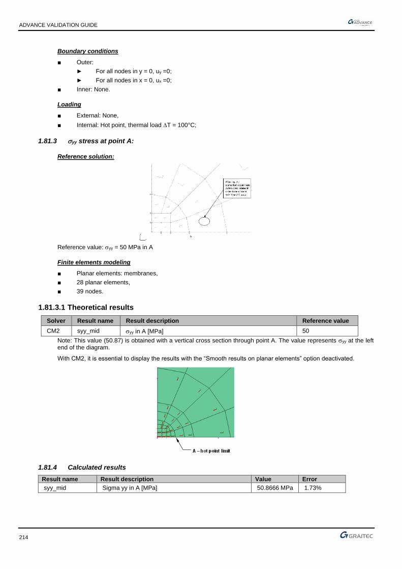
ADVANCE VALIDATION GUIDE
214
Boundary conditions
■ Outer:
► For all nodes in y = 0, uy =0;
► For all nodes in x = 0, ux =0;
■ Inner: None.
Loading
■ External: None,
■ Internal: Hot point, thermal load T = 100°C;
1.81.3 yy stress at point A:
Reference solution:
Reference value: yy = 50 MPa in A
Finite elements modeling
■ Planar elements: membranes,
■ 28 planar elements,
■ 39 nodes.
1.81.3.1 Theoretical results
Solver Result name Result description Reference value
CM2 syy_mid yy in A [MPa] 50
Note: This value (50.87) is obtained with a vertical cross section through point A. The value represents yy at the left end of the diagram.
With CM2, it is essential to display the results with the “Smooth results on planar elements” option deactivated.
1.81.4 Calculated results
Result name Result description Value Error
syy_mid Sigma yy in A [MPa] 50.8666 MPa 1.73%

ADVANCE VALIDATION GUIDE
215
1.82 Beam on 3 supports with T/C (k = 0) (01-0100SSNLB_FEM)
Test ID: 2514
Test status: Passed
1.82.1 Description
Verifies the rotation, the displacement and the moment on a beam consisting of two elements of the same length and identical characteristics with 3 T/C supports (k = 0).
1.82.2 Background
1.82.2.1 Model description
■ Reference: internal GRAITEC test;
■ Analysis type: static non linear;
■ Element type: linear, T/C.
Units
I. S.
Geometry
■ L= 10 m
■ Section: IPE 200, Iz = 0.00001943 m4
Materials properties
■ Longitudinal elastic modulus: E = 2.1 x 10¹¹ N/m2,
■ Poisson's ratio: = 0.3.
Boundary conditions
■ Outer:
► Support at node 1 restrained along x and y (x = 0),
► Support at node 2 restrained along y (x = 10 m),
► T/C stiffness ky = 0,
■ Inner: None.
Loading
■ External: Vertical punctual load P = -100 N at x = 5 m,
■ Internal: None.
1.82.2.2 References solutions
ky being null, the non linear model behaves the same way as the structure without support 3.
Displacements
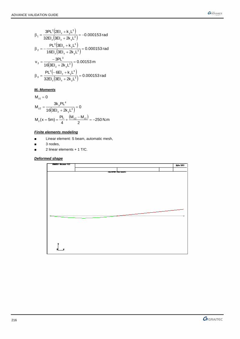
ADVANCE VALIDATION GUIDE
216
( )( )
( )( )
( )( )
( )rad 000153.0
Lk2EI3EI32
LkEI6PL
m 00153.0Lk2EI316
PL3v
rad 000153.0Lk2EI3EI16
LkEI3PL
rad 000153.0Lk2EI3EI32
LkEI2PL3
3yzz
3yz
2
3
3yz
3
3
3yzz
3yz
2
2
3yzz
3yz
2
1
=+
+−=
=+
−=
=+
+−=
−=+
+=
Mz Moments
( )( )
N.m 2502
MM
4
PL)m5x(M
0Lk2EI316
PLk3M
0M
1z2zz
3yz
4y
2z
1z
−=−
+==
=+
=
=
Finite elements modeling
■ Linear element: S beam, automatic mesh,
■ 3 nodes,
■ 2 linear elements + 1 T/C.
Deformed shape

ADVANCE VALIDATION GUIDE
217
Moment diagrams
1.82.2.3 Theoretical results
Solver Result name Result description Reference value
CM2 RY Rotation Ry in node 1 [rad] 0.000153
CM2 RY Rotation Ry in node 2 [rad] -0.000153
CM2 DZ Displacement V in node 3 [m] 0.00153
CM2 RY Rotation Ry in node 3 [rad] 0.000153
CM2 My Moment M in node 1 [Nm] 0
CM2 My Moment M - middle span 1 [Nm] -250
1.82.3 Calculated results
Result name Result description Value Error
RY Rotation Ry in node 1 [rad] 0.000153175 Rad 0.11%
RY Rotation Ry in node 2 [rad] -0.000153175 Rad -0.11%
DZ Displacement V in node 3 [m] 0.00153175 m 0.11%
RY Rotation Ry in node 3 [rad] -0.000153175 Rad -0.11%
My Moment M in node 1 [Nm] 1.42709e-13 N*m 0.00%
My Moment M - middle span 1 [Nm] -250 N*m 0.00%

ADVANCE VALIDATION GUIDE
218
1.83 Beam on 3 supports with T/C (k -> infinite) (01-0101SSNLB_FEM)
Test ID: 2515
Test status: Passed
1.83.1 Description
Verifies the rotation, the displacement and the moment on a beam consisting of two elements of the same length and identical characteristics with 3 T/C supports (k -> infinite).
1.83.2 Background
1.83.2.1 Model description
■ Reference: internal GRAITEC test;
■ Analysis type: static non linear;
■ Element type: linear, T/C.
Units
I. S.
Geometry
■ L= 10 m
■ Section: IPE 200, Iz = 0.00001943 m4
Materials properties
■ Longitudinal elastic modulus: E = 2.1 x 10¹¹ N/m2,
■ Poisson's ratio: = 0.3.
Boundary conditions
■ Outer:
► Support at node 1 restrained along x and y (x = 0),
► Support at node 2 restrained along y (x = 10 m),
► T/C stiffness ky → (1.1030N/m),
■ Inner: None.
Loading
■ External: Vertical punctual load P = -100 N at x = 5 m,
■ Internal: None.
1.83.2.2 References solutions
ky being infinite, the non linear model behaves the same way as a beam on 3 supports.

ADVANCE VALIDATION GUIDE
219
Displacements
( )( )
( )( )
( )( )
( )rad 000038.0
Lk2EI3EI32
LkEI6PL
0Lk2EI316
PL3v
rad 000077.0Lk2EI3EI16
LkEI3PL
rad 000115.0Lk2EI3EI32
LkEI2PL3
3yzz
3yz
2
3
3yz
3
3
3yzz
3yz
2
2
3yzz
3yz
2
1
−=+
+−=
=+
−=
=+
+−=
−=+
+=
Mz Moments
( )( )
N.m 13.2032
MM
4
PL)m5x(M
N.m 75.93Lk2EI316
PLk3M
0M
1z2zz
3yz
4y
2z
1z
−=−
+==
−=+
=
=
Finite elements modeling
■ Linear element: S beam, automatic mesh,
■ 3 nodes,
■ 2 linear elements + 1 T/C.
Deformed shape

ADVANCE VALIDATION GUIDE
220
Moment diagram
1.83.2.3 Theoretical results
Solver Result name Result description Reference value
CM2 RY Rotation Ry - node 1 [rad] 0.000115
CM2 RY Rotation Ry - node 2 [rad] -0.000077
CM2 DZ Displacement - node 3 [m] 0
CM2 RY Rotation Ry - node 3 [rad] 0.000038
CM2 My Moment M - node 1 [Nm] 0
CM2 My Moment M - node 2 [Nm] 93.75
CM2 My Moment M - middle span 1 [Nm] -203.13
1.83.3 Calculated results
Result name Result description Value Error
RY Rotation Ry in node 1 [rad] 0.000115005 Rad 0.00%
RY Rotation Ry in node 2 [rad] -7.65875e-05 Rad 0.54%
DZ Displacement - node 3 [m] 9.36486e-30 m 0.00%
RY Rotation Ry in node 3 [rad] 3.81695e-05 Rad 0.45%
My Moment M - node 1 [Nm] 1.3145e-13 N*m 0.00%
My Moment M - node 2 [Nm] 93.6486 N*m -0.11%
My Moment M - middle span 1 [Nm] -203.176 N*m -0.02%

ADVANCE VALIDATION GUIDE
221
1.84 Beam on 3 supports with T/C (k = -10000 N/m) (01-0102SSNLB_FEM)
Test ID: 2516
Test status: Passed
1.84.1 Description
Verifies the rotation, the displacement and the moment on a beam consisting of two elements of the same length and identical characteristics with 3 T/C supports (k = -10000 N/m).
1.84.2 Background
1.84.2.1 Model description
■ Reference: internal GRAITEC test;
■ Analysis type: static non linear;
■ Element type: linear, T/C.
Units
I. S.
Geometry
■ L= 10 m
■ Section: IPE 200, Iz = 0.00001943 m4
Materials properties
■ Longitudinal elastic modulus: E = 2.1 x 10¹¹ N/m2,
■ Poisson's ratio: = 0.3.
Boundary conditions
■ Outer:
► Support at node 1 restrained along x and y (x = 0),
► Support at node 2 restrained along y (x = 10 m),
► T/C ky Rigidity = -10000 N/m (the – sign corresponds to an upwards restraint),
■ Inner: None.
Loading
■ External: Vertical punctual load P = -100 N at x = 5 m,
■ Internal: None.
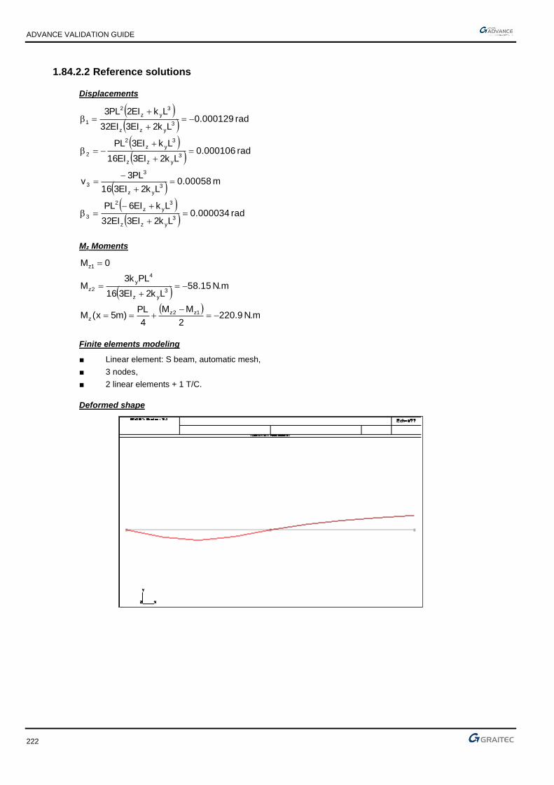
ADVANCE VALIDATION GUIDE
222
1.84.2.2 Reference solutions
Displacements
( )( )
( )( )
( )( )
( )rad 000034.0
Lk2EI3EI32
LkEI6PL
m 00058.0Lk2EI316
PL3v
rad 000106.0Lk2EI3EI16
LkEI3PL
rad 000129.0Lk2EI3EI32
LkEI2PL3
3yzz
3yz
2
3
3yz
3
3
3yzz
3yz
2
2
3yzz
3yz
2
1
=+
+−=
=+
−=
=+
+−=
−=+
+=
Mz Moments
( )( )
N.m 9.2202
MM
4
PL)m5x(M
N.m 15.58Lk2EI316
PLk3M
0M
1z2zz
3yz
4y
2z
1z
−=−
+==
−=+
=
=
Finite elements modeling
■ Linear element: S beam, automatic mesh,
■ 3 nodes,
■ 2 linear elements + 1 T/C.
Deformed shape

ADVANCE VALIDATION GUIDE
223
Moment diagram
1.84.2.3 Theoretical results
Solver Result name Result description Reference value
CM2 RY Rotation Ry in node 1 [rad] -0.000129
CM2 RY Rotation Ry in node 2 [rad] 0.000106
CM2 DZ Displacement - node 3 [m] 0.00058
CM2 RY Rotation Ry in node 3 [rad] 0.000034
CM2 My M moment - node 1 [Nm] 0
CM2 My M moment - node 2 [Nm] -58.15
CM2 My M moment - middle span 1 [Nm] -220.9
1.84.3 Calculated results
Result name Result description Value Error
RY Rotation Ry in node 1 [rad] 0.000129488 Rad 0.38%
RY Rotation Ry in node 2 [rad] -0.000105646 Rad 0.33%
DZ Displacement - node 3 [m] 0.000581169 m 0.20%
RY Rotation Ry in node 3 [rad] -3.44295e-05 Rad -1.26%
My M moment - node 1 [Nm] -1.42109e-14 N*m 0.00%
My M moment - node 2 [Nm] 58.1169 N*m -0.06%
My M moment - middle span 1 [Nm] -220.942 N*m -0.02%

ADVANCE VALIDATION GUIDE
224
1.85 Linear system of truss beams (01-0103SSLLB_FEM)
Test ID: 2517
Test status: Passed
1.85.1 Description
Verifies the displacement and the normal force for a bar system containing 4 elements of the same length and 2 diagonals.
1.85.2 Background
1.85.2.1 Model description
■ Reference: internal GRAITEC test;
■ Analysis type: static linear;
■ Element type: linear, bar.
Units
I. S.
Geometry
■ L= 5 m
■ Section S = 0.005 m2
Materials properties
Longitudinal elastic modulus: E = 2.1 x 10¹¹ N/m2.
Boundary conditions
■ Outer:
► Support at node 1 restrained along x and y,
► Support at node 2 restrained along x and y,
■ Inner: None.
Loading
■ External: Horizontal punctual load P = 50000 N at node 3,
■ Internal: None.

ADVANCE VALIDATION GUIDE
225
1.85.2.2 References solutions
Displacements
m 000108.0ES11
PL5v
m 000541.0ES11
PL25u
m 000129.0ES11
PL6v
m 000649.0ES11
PL30u
4
4
3
3
==
==
−=−
=
==
N normal forces
N 32141P11
25N N 22727P
11
5N
N 38569P11
26N N 27272P
11
6N
N 22727P11
5N 0N
4243
1323
1412
−=−===
==−=−=
===
Finite elements modeling
■ Linear element: bar, without meshing,
■ 4 nodes,
■ 6 linear elements.
Deformed shape

ADVANCE VALIDATION GUIDE
226
Normal forces
1.85.2.3 Theoretical results
Solver Result name Result description Reference value
CM2 DX u3 displacement on Node 3 [m] 0.000649
CM2 DZ v3 displacement on Node 3 [m] -0.000129
CM2 DX u4 displacement on Node 4 [m] 0.000541
CM2 DZ v4 displacement on Node 4 [m] 0.000108
CM2 Fx N12 normal force on Element 1 [N] 0
CM2 Fx N23 normal force on Element 2 [N] -27272
CM2 Fx N43 normal force on Element 3 [N] 22727
CM2 Fx N14 normal force on Element 4 [N] 22727
CM2 Fx N13 normal effort on Element 5 [N] 38569
CM2 Fx N42 normal force on Element 6 [N] -32141
1.85.3 Calculated results
Result name Result description Value Error
DX u3 displacement on Node 3 [m] 0.000649287 m 0.04%
DZ v3 displacement on Node 3 [m] -0.000129871 m -0.68%
DX u4 displacement on Node 4 [m] 0.000541063 m 0.01%
DZ v4 displacement on Node 4 [m] 0.000108224 m 0.21%
Fx N12 normal force on Element 1 [N] 0 N 0.00%
Fx N23 normal force on Element 2 [N] -27272.9 N 0.00%
Fx N43 normal force on Element 3 [N] 22727.1 N 0.00%
Fx N14 normal force on Element 4 [N] 22727.1 N 0.00%
Fx N13 normal effort on Element 5 [N] 38569.8 N 0.00%
Fx N42 normal force on Element 6 [N] -32140.9 N 0.00%

ADVANCE VALIDATION GUIDE
227
1.86 Non linear system of truss beams (01-0104SSNLB_FEM)
Test ID: 2518
Test status: Passed
1.86.1 Description
Verifies the displacement and the normal force for a bar system containing 4 elements of the same length and 2 diagonals.
1.86.2 Background
1.86.2.1 Model description
■ Reference: internal GRAITEC test;
■ Analysis type: static non linear;
■ Element type: linear, bar, tie.
Units
I. S.
Geometry
■ L= 5 m
■ Section S = 0.005 m2
Materials properties
Longitudinal elastic modulus: E = 2.1 x 10¹¹ N/m2.
Boundary conditions
■ Outer:
► Support at node 1 restrained along x and y,
► Support at node 2 restrained along x and y,
■ Inner: None.
Loading
■ External: Horizontal punctual load P = 50000 N at node 3,
■ Internal: None.

ADVANCE VALIDATION GUIDE
228
1.86.2.2 References solutions
In non linear analysis without large displacement, the introduction of ties for the diagonal bars removes bar 5 (test No. 0103SSLLB_FEM allows finding an compression force in this bar at the linear calculation).
Displacements
0v
m 000238.0ES
PLv
m 001195.0ES11
PL5uu
4
3
43
=
−=−=
===
N normal forces
0N 0N
N 70711P2N N 50000PN
0N 0N
4243
1323
1412
==
==−=−=
==
Finite elements modeling
■ Linear element: bar, without meshing,
■ 4 nodes,
■ 6 linear elements.
Deformed shape

ADVANCE VALIDATION GUIDE
229
Normal forces
1.86.2.3 Theoretical results
Solver Result name Result description Reference value
CM2 DX u3 displacement on Node 3 [m] 0.001195
CM2 DZ v3 displacement on Node 3 [m] -0.000238
CM2 DX u4 displacement on Node 4 [m] 0.001195
CM2 DZ v4 displacement on Node 4 [m] 0
CM2 Fx N12 normal force on Element 1 [N] 0
CM2 Fx N23 normal force on Element 2 [N] -50000
CM2 Fx N34 normal force on Element 3 [N] 0
CM2 Fx N14 normal force on Element 4 [N] 0
CM2 Fx N13 normal effort on Element 5 [N] 70711
CM2 Fx N24 normal force on Element 6 [N] 0
1.86.3 Calculated results
Result name Result description Value Error
DX u3 displacement on Node 3 [m] 0.00119035 m -0.39%
DZ v3 displacement on Node 3 [m] -0.000238095 m -0.04%
DX u4 displacement on Node 4 [m] 0.00119035 m -0.39%
DZ v4 displacement on Node 4 [m] 9.94686e-316 m 0.00%
Fx N12 normal force on Element 1 [N] 0 N 0.00%
Fx N23 normal force on Element 2 [N] -50000 N 0.00%
Fx N34 normal force on Element 3 [N] 0 N 0.00%
Fx N14 normal force on Element 4 [N] 2.08884e-307 N 0.00%
Fx N13 normal effort on Element 5 [N] 70710.7 N 0.00%
Fx N24 normal force on Element 6 [N] 0 N 0.00%

ADVANCE VALIDATION GUIDE
230
1.87 PS92 - France: Study of a mast subjected to an earthquake (02-0112SMLLB_P92)
Test ID: 2519
Test status: Passed
1.87.1 Description
A structure consisting of 2 beams and 2 punctual masses, subjected to a lateral earthquake along X. The frequency modes, the eigen vectors, the participation factors, the displacement at the top of the mast and the forces at the top of the mast are verified.
1.87.1.1 Model description
■ Reference: internal GRAITEC test;
■ Analysis type: modal and spectral analyses;
■ Element type: linear, mass.
1.87.1.2 Material strength model
Units
I. S.
Geometry
■ Length: L= 35.00 m,
■ Outer radius: Rext= 3.00 m,
■ Inner radius: Rint= 2.80 m,
■ Axial section: S= 3.644 m2,
■ Polar inertia: Ip= 30.68 m4,
■ Bending inertias: Ix= 15.34 m4,
Iy= 15.34 m4,
Masses
■ M1= 203873.6 kg
■ M2= 101936.8 kg
Materials properties
■ Longitudinal elastic modulus: E= 1.962 x 10¹⁰ N/m2,
■ Poisson's ratio: = 0.1,
■ Density: = 25 kN/m3,
Boundary conditions
■ Outer: Fixed in X= 0.00m, Y= 0.00 m,
Loading
■ External: Seismic excitation on X direction

ADVANCE VALIDATION GUIDE
231
Finite elements modeling
Linear element: beam, automatic mesh,
1.87.1.3 Seismic hypothesis in conformity with PS92 regulation
■ Zone: Nice Sophia Antipolis (Zone II) ;
■ Site: S1 (Medium soil, 10m thickness);
■ Construction type class: B;
■ Behavior coefficient: 3;
■ Material damping: 4% (Reinforced concrete).
1.87.1.4 Modal analysis
Eigen periods reference solution
Substract the value of structure’s specific horizontal periods by solving the following equation:
( ) 0MKdet 2 =−
−
−
2
1
3
M0
0MM
25
516
L7
EI48K
Eigen modes Units Reference
1 Hz 2.085
2 Hz 10.742
Modal vectors
For 1:
=
=
−
−
−
055.3
1
U
U0
U
U
M0
0M
25
516
L7
EI48
2
1
1
2
1
12
2
2
11
3
For 2:
−=
655.0
1
U
U
2
1
2
Normalizing relative to the mass
−
−
3
4
110842.2
10305.9 ;
−
−
−
3
3
210316.1
1001.2

ADVANCE VALIDATION GUIDE
232
Modal deformations
1.87.1.5 Spectral study
Design spectrum
Nominal acceleration:
2n1 sm5411.5a 2.085Hzf ==
2n2 sm25.6aHz742.01f ==
Observation: the gap between pulses is greater than 10%, so the modal responses can be regarded as independent.
Reference participation factors
= Mii
séismedudirectionladedirecteurVecteur:
Eigen modes Reference
1 479.427
2 275.609
Pseudo-acceleration
iiii a = in (m/s2)
4.0
%5
= : Damping correction factor,

ADVANCE VALIDATION GUIDE
233
: Structure damping.
=
8.2556
2.70261
=
2.4783-
3.78521
Reference modal displacement
−
−=
024.814E
021.576E1
−
−=
045.446E-
048.318E2
Equivalent static forces
+
+=
058.415E
055.510EF1
+
+=
052.526E-
057.717EF2
Displacement at the top of the mast
( ) ( )( )22
1 04E446.502E81.4U −−+−=
Units Reference
m 4.814 E-02
Shear force at the top of the mast
( ) ( )( )3
05E526.205E415.8T
22
1
+−++=
3: Being the behavior coefficient of forces
Units Reference
N 2.929 E+05
Moment at the base
𝑴 = 𝟑𝟓𝒙√(𝟖. 𝟒𝟏𝟓𝑬 + 𝟎. 𝟓)𝟐 + (𝟐. 𝟓𝟐𝟔𝑬 + 𝟎. 𝟓)𝟐 + 𝟏𝟕. 𝟓𝒙√((𝟓. 𝟓𝟏𝑬 + 𝟎. 𝟓)𝟐 + (𝟕. 𝟕𝟏𝟕𝑬 + 𝟎. 𝟓)𝟐)
𝟑
Units Reference
N.m 1.578 E+07
1.87.1.6 Theoretical results
Reference
Solver Result name Result description Reference value
CM2 Frequency Frequency Mode 1 [Hz] 2.085
CM2 Frequency Frequency Mode 2 [Hz] 10.742
CM2 D Displacement at the top of the mast [cm] 4.814
CM2 Fz Forces at the top of the mast [N] 2.929E+05
1.87.2 Calculated results
Result name Result description Value Error
Frequency Frequency Mode 1 [Hz] 2.08 Hz -0.24%
Frequency Frequency Mode 2 [Hz] 10.74 Hz -0.02%
D Displacement at the top of the mast [cm] 4.81159 cm -0.05%
Fz Forces at the top of the mast [N] 292677 N -0.08%

ADVANCE VALIDATION GUIDE
234
1.88 BAEL 91 (concrete design) - France: Linear element in combined bending/tension - without compressed reinforcements - Partially tensioned section (02-0158SSLLB_B91)
Test ID: 2520
Test status: Passed
1.88.1 Description
Verifies the reinforcement results for a concrete beam with 8 isostatic spans subjects to uniform loads and compression normal forces.
1.88.1.1 Model description
■ Reference: J. Perchat (CHEC) reinforced concrete course
■ Analysis type: static linear;
■ Element type: planar.
Units
■ Forces: kN
■ Moment: kN.m
■ Stresses: MPa
■ Reinforcement density: cm²
Geometry
■ Beam dimensions: 0.2 x 0.5 ht
■ Length: l = 48 m in 8 spans of 6m,
Materials properties
■ Longitudinal elastic modulus: E = 20000 MPa,
■ Poisson's ratio: = 0.
Boundary conditions
■ Outer:
► Hinged at end x = 0,
► Vertical support at the same level with all other supports
■ Inner: Hinged at each beam end (isostatic)
Loading
■ External:
► Case 1 (DL):uniform linear load g= -5kN/m (on all spans except 8)
Fx = 10 kN at x = 42m: Ng = -10 kN for spans from 6 to 7
Fx = 140 kN at x = 32m: Ng = -150 kN for span 5
Fx = -50 kN at x = 24m: Ng = -100 kN for span 4
Fx = 50 kN at x = 18m: Ng = -50 kN for span 3
Fx = 50 kN at x = 12m: Ng = -100 kN for span 2
Fx = -70 kN at x = 6m: Ng = -30 kN for span 1
► Case 10 (DL):uniform linear load g = -5 kN/m (span 8)
Fx = 10 kN at x = 48m: Ng = -10 kN
Fx = -10 kN at x = 42m
► Case 2 to 8 (LL):uniform linear load q = -9 kN/m (on spans 1, 3 to 7)

ADVANCE VALIDATION GUIDE
235
uniform linear load q = -15 kN/m (on span 2)
Fx = 30 kN at x = 6m (case 2 span 1)
Fx = -50 kN at x = 6m (case 3 span 2)
Fx = 50 kN at x = 12m (case 3 span 2)
Fx = -40 kN at x = 12m (case 4 span 3)
Fx = 40 kN at x = 18m (case 4 span 3)
Fx = -100 kN at x = 18m (case 5 span 4)
Fx = 100 kN at x = 24m (case 5 span 4)
Fx = -150 kN at x = 24m (case 6 span 5)
Fx = 150 kN at x = 30m (case 6 span 5)
Fx = -8 kN at x = 30m (case 7 span 6)
Fx = 8 kN at x = 36m (case 7 span 6)
Fx = -8 kN at x = 36m (case 8 span 7
Fx = 8 kN at x = 42m (case 8 span 7)
► Case 9 (ACC):uniform linear load a = -25 kN/m (on 8th span)
Fx = 8 kN at x = 36m (case 9 span 8)
Fx = -8 kN at x = 42m (case 9 span 8)
Comb BAELUS: 1.35xDL+1.5xLL with duration of more than 24h (comb 101, 104 to 107)
Comb BAEULI: 1.35xDL+1.5xLL with duration between 1h and 24h (comb 102)
Comb BAELUC: 1.35xDL + 1.5xLL with duration of less than 1h (comb 103)
Comb BAELS: 1xDL + 1*LL (comb 108 to 114)
Comb BAELA: 1xDL + 1xACC with duration of less than 1h (comb 115)
■ Internal: None.
Reinforced concrete calculation hypothesis:
All concrete covers are set to 5 cm
BAEL 91 calculation (according to 99 revised version)
Span Concrete Reinforcement Application Concrete Cracking
1 B20 HA fe500 D>24h No Non prejudicial
2 B35 Adx fe235 1h<D<24h No Non prejudicial
3 B50 HA fe 400 D<1h Yes Non prejudicial
4 B25 HA fe500 D>24h Yes Prejudicial
5 B25 HA fe500 D>24h No Very prejudicial
6 B30 Adx fe235 D>24h Yes Prejudicial
7 B40 HA fe500 D>24h Yes 160 MPa
8 B45 HA fe500 D<1h Yes Non prejudicial
1.88.1.2 Reinforcement calculation
Reference solution
Span 1 Span 2 Span 3 Span 4 Span 5 Span 6 Span 7 Span 8
fc28 20 35 50 25 25 30 40 45
ft28 1.8 2.7 3.6 2.1 2.1 2.4 3 3.3
fe 500 235 400 500 500 235 500 500

ADVANCE VALIDATION GUIDE
236
Span 1 Span 2 Span 3 Span 4 Span 5 Span 6 Span 7 Span 8
teta 1 0.9 0.85 1 1 1 1 0.85
gamb 1.5 1.5 1.5 1.5 1.5 1.5 1.5 1.15
gams 1.15 1.15 1.15 1.15 1.15 1.15 1.15 1
h 1.6 1 1.6 1.6 1.6 1 1.6 1.6
fbu 11.33 22.04 33.33 14.17 14.17 17.00 22.67 39.13
fed 434.78 204.35 347.83 434.78 434.78 204.35 434.78 500.00
sigpreju 250.00 156.67 264.00 250.00 250.00 156.67 160.00 252.76
sigtpreju 200.00 125.33 211.20 200.00 200.00 125.33 160.00 202.21
g 5.00 5.00 5.00 5.00 5.00 5.00 5.00 5.00
q 9.00 15.00 9.00 9.00 9.00 9.00 9.00 25.00
pu 20.25 29.25 20.25 20.25 20.25 20.25 20.25 30.00
pser 14.00 20.00 14.00 14.00 14.00 14.00 14.00
G -30.00 -100.00 -50.00 -100.00 -150.00 -10.00 -10.00 -10.00
Q -30.00 -50.00 -40.00 -100.00 -100.00 -8.00 -8.00 -8.00
l 6.00 6.00 6.00 6.00 6.00 6.00 6.00 6.00
Mu 91.13 131.63 91.13 91.13 91.13 91.13 91.13 135.00
Nu -85.50 -210.00 -127.50 -285.00 -352.50 -25.50 -25.50 -18.00
Mser 63.00 90.00 63.00 63.00 63.00 63.00 63.00
Nser -60.00 -150.00 -90.00 -200.00 -250.00 -18.00 -18.00
Vu 60.75 87.75 60.75 60.75 60.75 60.75 60.75 90.00
Main reinforcement calculation according to ULS
Mu/A 74.03 89.63 65.63 34.13 20.63 86.03 86.03 131.40
ubu 0.161 0.100 0.049 0.059 0.036 0.125 0.094 0.083
a 0.221 0.133 0.062 0.077 0.046 0.167 0.123 0.108
z 0.410 0.426 0.439 0.436 0.442 0.420 0.428 0.430
Au 6.12 20.57 7.97 8.35 9.18 11.27 5.21 6.46
Main reinforcement calculation with prejudicial cracking according to SLS
Mser/A 51.000 60.000 45.000 23.000 13.000 59.400 59.400 0.000
a 0.4186 0.6678 0.6303 0.4737 0.4737 0.6328 0.6923 0.6157
Mrb 87.53 220.78 302.44 121.16 121.16 182.01 258.82 267.55
A 1.0000 1.0000 1.0000 1.0000 1.0000 1.0000 1.0000 1.0000
B -3.0000 -3.0000 -3.0000 -3.0000 -3.0000 -3.0000 -3.0000 -3.0000
C -0.4533 -0.8511 -0.3788 -0.2044 -0.1156 -0.8426 -0.8250 0.0000
D 0.4533 0.8511 0.3788 0.2044 0.1156 0.8426 0.8250 0.0000
alpha1 0.238 0.432 0.428
z 0.414 0.385 0.386
Aserp 10.22 10.99 10.75
Main reinforcement calculation with very prejudicial cracking according to SLS
Mser/A 51.00 60.00 45.00 23.00 13.00 59.40 59.40 0.00
a 0.47 0.72 0.68 0.53 0.53 0.68 0.69 0.67
Mrb 96.93 231.67 319.66 132.43 132.43 192.27 258.82 283.60
A 1.0000 1.0000 1.0000 1.0000 1.0000 1.0000 1.0000 1.0000
B -3.0000 -3.0000 -3.0000 -3.0000 -3.0000 -3.0000 -3.0000 -3.0000
C -0.5667 -1.0638 -0.4735 -0.2556 -0.1444 -1.0532 -0.8250 0.0000
D 0.5667 1.0638 0.4735 0.2556 0.1444 1.0532 0.8250 0.0000
alpha1 0.203
z 0.420
Asertp 14.049
Transverse reinforcement calculation
tu 0.68 0.98 0.68 0.68 0.68 0.68 0.68 1.00
k 0.57 0.40 0.00 -0.14 -0.41 0.00 0.00 0.00

ADVANCE VALIDATION GUIDE
237
Span 1 Span 2 Span 3 Span 4 Span 5 Span 6 Span 7 Span 8
At/st 1.87 7.08 4.31 3.90 4.77 7.34 3.45 4.44
Recapitulation
Aflex 6.12 20.57 7.97 10.22 14.05 11.27 10.75 6.46
e0 -0.95 -1.67 -1.43 -3.17 -3.97 -0.29 -0.29 -0.13
Aminfsimp 0.75 2.38 1.86 0.87 0.87 2.11 1.24 1.37
Aminfcomp 0.83 2.54 2.01 0.90 0.90 2.80 1.65 0.30
At 1.87 7.08 4.31 3.90 4.77 7.34 3.45 4.44
Atmin 1.60 3.40 2.00 1.60 1.60 3.40 1.60 1.60
Finite elements modeling
■ Linear elements: beams with imposed mesh
■ 29 nodes,
■ 28 linear elements.
1.88.1.3 Theoretical results
Solver Result name Result description Reference value
CM2 Az Inf. main reinf. T1 [cm2] 6.12
CM2 Amin Min. main reinf. T1 [cm2] 0.75
CM2 Atz Trans. reinf. T1 [cm2] 1.87
CM2 Az Inf. main reinf. T2 [cm2] 20.57
CM2 Amin Min. main reinf. T2 [cm2] 2.38
CM2 Atz Trans. reinf. T2 [cm2] 7.08
CM2 Az Inf. main reinf. T3 [cm2] 7.97
CM2 Amin Min. main reinf. T3 [cm2] 1.86
CM2 Atz Trans. reinf. T3 [cm2] 4.31
CM2 Az Inf. main reinf. T4 [cm2] 10.22
CM2 Amin Min. main reinf. T4 [cm2] 0.87
CM2 Atz Trans. reinf. T4 [cm2] 3.90
CM2 Az Inf. main reinf. T5 [cm2] 14.05
CM2 Amin Min. main reinf. T5 [cm2] 4.20
CM2 Atz Trans. reinf. T5 [cm2] 4.77
CM2 Az Inf. main reinf. T6 [cm2] 11.27
CM2 Amin Min. main reinf. T6 [cm2] 2.11
CM2 Atz Trans. reinf. T6 [cm2] 7.34
CM2 Az Inf. main reinf. T7 [cm2] 10.75
CM2 Amin Min. main. reinf. T7 [cm2] 1.24
CM2 Atz Trans. reinf. T7 [cm2] 3.45
CM2 Az Inf. main reinf. T8 [cm2] 6.46
CM2 Amin Min. main reinf. T8 [cm2] 1.37
CM2 Atz Trans. reinf. T8 [cm2] 4.44
The "Mu limit" method must be applied in order to achieve the same results.

ADVANCE VALIDATION GUIDE
238
1.88.2 Calculated results
Result name Result description Value Error
Az Inf. Main reinf. T1 [cm²] -6.11718 cm² 0.05%
Amin Min. main reinf. T1 [cm²] 0.7452 cm² -0.64%
Atz Trans. Reinf. T1 [cm²] 1.8699 cm² -0.01%
Az Inf. Main reinf. T2 [cm²] -20.5688 cm² 0.01%
Amin Min. main reinf. T2 [cm²] 2.3783 cm² -0.07%
Atz Trans. Reinf. T2 [cm²] 7.07943 cm² -0.01%
Az Inf. Main reinf. T3 [cm²] -7.96552 cm² 0.06%
Amin Min. main reinf. T3 [cm²] 1.863 cm² 0.16%
Atz Trans. Reinf. T3 [cm²] 4.3125 cm² 0.06%
Az Inf. Main reinf. T4 [cm²] -10.2301 cm² -0.10%
Amin Min. main reinf. T4 [cm²] 0.8694 cm² -0.07%
Atz Trans. Reinf. T4 [cm²] 3.9008 cm² 0.02%
Az Inf. Main reinf. T5 [cm²] -14.0512 cm² -0.01%
Amin Min. main reinf. T5 [cm²] 4.2 cm² 0.00%
Atz Trans. Reinf. T5 [cm²] 4.7702 cm² 0.00%
Az Inf. Main reinf. T6 [cm²] -11.2742 cm² -0.04%
Amin Min. main reinf. T6 [cm²] 2.11404 cm² 0.19%
Atz Trans. Reinf. T6 [cm²] 7.34043 cm² 0.01%
Az Inf. Main reinf. T7 [cm²] -10.7634 cm² -0.12%
Amin Min. main. Reinf. T7 [cm²] 1.242 cm² 0.16%
Atz Trans. Reinf. T7 [cm²] 3.45 cm² 0.00%
Az Inf. Main reinf. T8 [cm²] -6.47718 cm² -0.27%
Amin Min. main reinf. T8 [cm²] 1.3662 cm² -0.28%
Atz Trans. Reinf. T8 [cm²] 4.44444 cm² 0.10%

ADVANCE VALIDATION GUIDE
239
1.89 BAEL 91 (concrete design) - France: Linear element in simple bending - without compressed reinforcement (02-0162SSLLB_B91)
Test ID: 2521
Test status: Passed
1.89.1 Description
Verifies the reinforcement results for a concrete beam with 8 isostatic spans subjected to uniform loads.
1.89.1.1 Model description
■ Reference: J. Perchat (CHEC) reinforced concrete course
■ Analysis type: static linear;
■ Element type: planar.
Units
■ Forces: kN
■ Moment: kN.m
■ Stresses: MPa
■ Reinforcement density: cm2
Geometry
■ Beam dimensions: 0.2 x 0.5 ht
■ Length: l = 42 m in 7 spans of 6m,
Materials properties
■ Longitudinal elastic modulus: E = 20000 MPa,
■ Poisson's ratio: = 0.
Boundary conditions
■ Outer:
► Hinged at end x = 0,
► Vertical support at the same level with all other supports
■ Inner: Hinge z at each beam end (isostatic)
Loading
■ External:
► Case 1 (DL):uniform linear load g = -5 kN/m (on all spans except 8)
► Case 2 to 8 (LL):uniform linear load q = -9 kN/m (on spans 1, 3 to 7)
uniform linear load q = -15 kN/m (on span 2)
► Case 9 (ACC): uniform linear load a = -25 kN/m (on 8th span)
► Case 10 (DL):uniform linear load g = -5 kN/m (on 8th span)
Comb BAELUS: 1.35xDL+1.5xLL with duration of more than 24h (comb 101, 104 to 107)
Comb BAEULI: 1.35xDL+1.5xLL with duration between 1h and 24h (comb 102)
Comb BAELUC: 1.35xDL + 1.5xLL with duration of less than 1h (comb 103)
Comb BAELS: 1xDL + 1*LL (comb 108 to 114)
Comb BAELUA: 1xDL + 1xACC (comb 115)
■ Internal: None.

ADVANCE VALIDATION GUIDE
240
Reinforced concrete calculation hypothesis:
■ All concrete covers are set to 5 cm
■ BAEL 91 calculation with the revised version 99
Span Concrete Reinforcement Application Concrete Cracking
1 B20 HA fe500 D>24h No Non prejudicial
2 B35 Adx fe235 1h<D<24h No Non prejudicial
3 B50 HA fe 400 D<1h Yes Non prejudicial
4 B25 HA fe500 D>24h Yes Prejudicial
5 B60 HA fe500 D>24h No Very prejudicial
6 B30 Adx fe235 D>24h Yes Prejudicial
7 B40 HA fe500 D>24h Yes 160 MPa
8 B45 HA fe500 D<1h Yes Non prejudicial
1.89.1.2 Reinforcement calculation
Reference solution
Span 1 Span 2 Span 3 Span 4 Span 5 Span 6 Span 7 Span 8
fc28 20 35 50 25 60 30 40 45 ft28 1.8 2.7 3.6 2.1 4.2 2.4 3 3.3 fe 500 235 400 500 500 235 500 500
teta 1 0.9 0.85 1 1 1 1 0.85 gamb 1.5 1.5 1.5 1.5 1.5 1.5 1.5 1.15 gams 1.15 1.15 1.15 1.15 1.15 1.15 1.15 1
h 1.6 1 1.6 1.6 1.6 1 1.6 1.6
fbu 11.33 22.04 33.33 14.17 34.00 17.00 22.67 39.13 fed 434.78 204.35 347.83 434.78 434.78 204.35 434.78 500.00
sigpreju 250.00 156.67 264.00 250.00 285.15 156.67 160.00 252.76 sigtpreju 200.00 125.33 211.20 200.00 228.12 125.33 160.00 202.21
g 5.00 5.00 5.00 5.00 5.00 5.00 5.00 5.00 q 9.00 15.00 9.00 9.00 9.00 9.00 9.00 25.00
pu 20.25 29.25 20.25 20.25 20.25 20.25 20.25 30.00 pser 14.00 20.00 14.00 14.00 14.00 14.00 14.00
l 6.00 6.00 6.00 6.00 6.00 6.00 6.00 6.00 Mu 91.13 131.63 91.13 91.13 91.13 91.13 91.13 135.00
Mser 63.00 90.00 63.00 63.00 63.00 63.00 63.00 Vu 60.75 87.75 60.75 60.75 60.75 60.75 60.75 90.00
Longitudinal reinforcement calculation according to ELU
ubu 0.199 0.147 0.068 0.159 0.066 0.132 0.099 0.085 a 0.279 0.200 0.087 0.217 0.086 0.178 0.131 0.111 z 0.400 0.414 0.434 0.411 0.435 0.418 0.426 0.430
Au 5.24 15.56 6.03 5.10 4.82 10.67 4.91 6.28
Main reinforcement calculation with prejudicial cracking according to SLS
A 1.000 1.000 1.000 1.000 1.000 1.000 1.000 1.000 B -3.000 -3.000 -3.000 -3.000 -3.000 -3.000 -3.000 -3.000 C -0.56000 -0.89362 -0.87500 D 0.56000 0.89362 0.87500
alpha1 0.367 0.442 0.438 z 0.395 0.384 0.384
Aserp 6.38 10.48 10.25
Main reinforcement calculation with very prejudicial cracking according to SLS
A 1.00 1.00 1.00 1.00 1.00 1.00 1.00 1.00 B -3.00 -3.00 -3.00 -3.00 -3.00 -3.00 -3.00 -3.00 C -0.70 -1.60 -0.66 -0.70 -0.61371 -1.12 -0.88 0.00 D 0.70 1.60 0.66 0.70 0.61371 1.12 0.88 0.00
alpha1 0.381 z 0.393
Asertp 7.030

ADVANCE VALIDATION GUIDE
241
Span 1 Span 2 Span 3 Span 4 Span 5 Span 6 Span 7 Span 8
Transversal reinforcement calculation
tu 0.68 0.98 0.68 0.68 0.68 0.68 0.68 1.00 k 1.00 1.00 0.00 0.00 0.00 0.00 0.00 0.00
At/st 0.69 1.79 4.31 3.45 3.45 7.34 3.45 4.44
Recapitulation
Aflex 5.24 15.56 6.03 6.38 7.03 10.67 10.25 6.28 Aminflex 0.75 2.38 1.86 0.87 1.74 2.11 1.24 1.37
At 0.69 1.79 4.31 3.45 3.45 7.34 3.45 4.44 Atmin 1.60 3.40 2.00 1.60 1.60 3.40 1.60 1.60
Finite elements modeling
■ Linear elements: beams with imposed mesh
■ 29 nodes,
■ 28 linear elements.
1.89.1.3 Theoretical results
Reference
Solver Result name Result description Reference value
CM2 Az Inf. main reinf. T1 [cm2] 5.24
CM2 Amin Min. main reinf. T1 [cm2] 0.75
CM2 Atz Trans. reinf. T1 [cm2] 0.69
CM2 Az Inf. main reinf. T2 [cm2] 15.56
CM2 Amin Min. main reinf. T2 [cm2] 2.38
CM2 Atz Trans. reinf. T2 [cm2] 1.79
CM2 Az Inf. main reinf. T3 [cm2] 6.03
CM2 Amin Min. main reinf. T3 [cm2] 1.86
CM2 Atz Trans. reinf. T3 [cm2] 4.31
CM2 Az Inf. main reinf. T4 [cm2] 6.38
CM2 Amin Min. main reinf. T4 [cm2] 0.87
CM2 Atz Trans. reinf. T4 [cm2] 3.45
CM2 Az Inf. main reinf. T5 [cm2] 7.03
CM2 Amin Min. main reinf. T5 [cm2] 1.74
CM2 Atz Trans. reinf. T5 [cm2] 3.45
CM2 Az Inf. main reinf. T6 [cm2] 10.67
CM2 Amin Min. main reinf. T6 [cm2] 2.11
CM2 Atz Trans. reinf. T6 [cm2] 7.34
CM2 Az Inf. main reinf. T7 [cm2] 10.25
CM2 Amin Min. main. reinf. T7 [cm2] 1.24
CM2 Atz Trans. reinf. T7 [cm2] 3.45
CM2 Az Inf. main reinf. T8 [cm2] 6.28
CM2 Amin Min. main reinf. T8 [cm2] 1.37
CM2 Atz Trans. reinf. T8 [cm2] 4.44
The "Mu limit" method must be applied to attain the same results.

ADVANCE VALIDATION GUIDE
242
1.89.2 Calculated results
Result name Result description Value Error
Az Inf. main reinf. T1 [cm²] -5.24348 cm² -0.07%
Amin Min. main reinf. T1 [cm²] 0.7452 cm² -0.64%
Atz Trans. reinf. T1 [cm²] 0.69 cm² 0.00%
Az Inf. main reinf. T2 [cm²] -15.5613 cm² -0.01%
Amin Min. main reinf. T2 [cm²] 2.3783 cm² -0.07%
Atz Trans. reinf. T2 [cm²] 1.79433 cm² 0.24%
Az Inf. main reinf. T3 [cm²] -6.03286 cm² -0.05%
Amin Min. main reinf. T3 [cm²] 1.863 cm² 0.16%
Atz Trans. reinf. T3 [cm²] 4.3125 cm² 0.06%
Az Inf. main reinf. T4 [cm²] -6.38336 cm² -0.05%
Amin Min. main reinf. T4 [cm²] 0.8694 cm² -0.07%
Atz Trans. reinf. T4 [cm²] 3.45 cm² 0.00%
Az Inf. main reinf. T5 [cm²] -7.03527 cm² -0.07%
Amin Min. main reinf. T5 [cm²] 1.7388 cm² -0.07%
Atz Trans. reinf. T5 [cm²] 3.45 cm² 0.00%
Az Inf. main reinf. T6 [cm²] -10.6698 cm² 0.00%
Amin Min. main reinf. T6 [cm²] 2.11404 cm² 0.19%
Atz Trans. reinf. T6 [cm²] 7.34043 cm² 0.01%
Az Inf. main reinf. T7 [cm²] -10.2733 cm² -0.23%
Amin Min. main. reinf. T7 [cm²] 1.242 cm² 0.16%
Atz Trans. reinf. T7 [cm²] 3.45 cm² 0.00%
Az Inf. main reinf. T8 [cm²] -6.29338 cm² -0.21%
Amin Min. main reinf. T8 [cm²] 1.3662 cm² -0.28%
Atz Trans. reinf. T8 [cm²] 4.44444 cm² 0.10%

ADVANCE VALIDATION GUIDE
243
1.90 CM66 (steel design) - France: Design of a Steel Structure (03-0206SSLLG_CM66)
Test ID: 2522
Test status: Passed
1.90.1 Description
Verifies the steel calculation results (maximum displacement, normal force, bending moment, deflections, buckling lengths, lateral-torsional buckling and cross section optimization) for a simple metallic framework with a concrete floor, according to CM66.
1.90.2 Background
1.90.2.1 Model description
■ Calculation model: Simple metallic framework with a concrete floor.
■ Load case:
► Permanent loads: 150 kg/m² for the floor and 25kg/m² for the roof.
► Overloads: 250 kg/m² on the floor.
► Wind loads on region II for a normal location
► Snow loads on region 2B at an altitude of 750m.
■ CM66 Combinations
Model preview
Structure’s load case
Code No. Type Title
CMP 1 Static SW + Dead loads CMS 2 Static Overloads for usage CMV 3 Static Wind overloads along +X in overpressure CMV 4 Static Wind overloads along +X in depression CMV 5 Static Wind overloads along -X in overpressure CMV 6 Static Wind overloads along -X in depression CMV 7 Static Wind overloads along +Z in overpressure CMV 8 Static Wind overloads along +Z in depression CMV 9 Static Wind overloads along -Z in overpressure CMV 10 Static Wind overloads along -Z in depression CMN 11 Static Normal snow overloads

ADVANCE VALIDATION GUIDE
244
1.90.2.2 Effel Structure results
Displacement Envelope (“CMCD" load combinations)
Envelope of linear element forces
Env. Case No. Max.
location
D DX DY DZ
(cm) (cm) (cm) (cm)
Max(D) 213 148 CENTER 12.115 0.037 12.035 -1.393
Min(D) 188 1.1 START 0.000 0.000 0.000 0.000
Max(DX) 204 72.1 START 3.138 3.099 0.434 0.244
Min(DX) 204 313 END 2.872 -1.872 -0.129 -2.174
Max(DY) 213 148 CENTER 12.115 0.037 12.035 -1.393
Min(DY) 213 61.5 END 9.986 -0.118 -9.985 0.046
Max(DZ) 201 371 CENTER 4.149 -0.006 -0.188 4.145
Min(DZ) 203 370 CENTER 4.124 -0.006 -0.240 -4.118
Envelope of forces on linear elements (“CMCFN” load combinations)
Envelope of linear element forces
Env. Case No. MaxSite Fx Fy Fz Mx My Mz
(T) (T) (T) (T*m) (T*m) (T*m)
Max (Fx) 120 4.1 START 19.423 -4.108 -1.384 -0.003 1.505 7.551
Min (Fx) 138 98 START -41.618 -0.962 -0.192 0.000 0.000 0.000
Max(Fy) 120 57 END -13.473 16.349 -0.016 -0.003 0.002 55.744
Min(Fy) 120 60 START -15.994 -16.112 -0.006 -3E-004 6E-006 53.096
Max(Fz) 177 371 START -3.486 -0.118 2.655 0.000 0.000 0.000
Min(Fz) 187 370 START -3.666 -0.147 -2.658 0.000 0.000 0.000
Max(Mx) 120 111 END 3.933 4.840 0.278 0.028 -4E-005 11.531
Min(Mx) 120 21 END -22.324 13.785 -0.191 -0.028 -0.004 42.562
Max(My) 177 371 CENTER -3.099 -0.118 -0.323 0.000 4.403 -0.500
Min(My) 179 370 CENTER -3.283 -0.155 0.321 0.000 -4.373 -0.660
Max (Mz) 120 57 END -13.473 16.349 -0.016 -0.003 0.002 55.744
Min (Mz) 120 59.2 END -19.455 -8.969 -0.702 -0.003 -0.001 -57.105
Envelope of linear element stresses (“CMCFN” load combinations)
Envelope of linear element stresses
Env. Case No. MaxSite sxxMax sxyMax sxzMax sFxx sMxxMax
(MPa) (MPa) (MPa) (MPa) (MPa)
Max(sxxMax) 120 59.2 END 273.860 -14.696 -1.024 -16.453 290.312
Min(sxxMax) 120 292 START -150.743 0.000 0.000 -150.743 0.000
Max(sxyMax) 120 57 START 262.954 37.139 -0.030 -15.609 278.562
Min(sxyMax) 120 60 END 241.643 -36.595 -0.011 -18.536 260.179
Max(sxzMax) 185 371 START -2.949 -0.183 3.876 -2.949 0.000
Min(sxzMax) 179 370 START -3.104 -0.255 -3.882 -3.104 0.000
Max(sFxx) 120 293 END 161.095 9E-005 -0.002 161.095 0.000
Min(sFxx) 120 292 START -150.743 0.000 0.000 -150.743 0.000
Max(sMxxMax) 120 59.2 END 273.860 -14.696 -1.024 -16.453 290.312
Min(sMxxMax) 1 1.1 START -4.511 3.155 -0.646 -4.511 0.000
1.90.2.3 CM66 Effel Expertise results
Hypotheses
For columns
■ Deflections: 1/150
Envelopes deflections calculation.
■ Buckling XY plane: Automatic calculation of the structure on displaceable nodes
XZ plane: Automatic calculation of the structure on fixed nodes
■ Lateral-torsional buckling: Ldi automatic calculation: hinged restraint

ADVANCE VALIDATION GUIDE
245
Lds automatic calculation: hinged restraint
For rafters
■ Deflections: 1/200
Envelopes deflections calculation.
■ Buckling: XY plane: Automatic calculation of the structure on displaceable nodes
XZ plane: Automatic calculation of the structure on fixed nodes
■ Lateral-torsional buckling: Ldi automatic calculation: no restraint
Lds automatic calculation: hinged restraint
For columns
■ Deflections: 1/150
Envelopes deflections calculation.
■ Buckling: XY plane: Automatic calculation of the structure on displaceable nodes
XZ plane: Automatic calculation of the structure on displaceable nodes
■ Lateral-torsional buckling: Ldi automatic calculation: hinged restraint
Lds automatic calculation: hinged restraint
Optimization parameters
■ Work ratio optimization between 90 and 100%
■ All the sections from the library are available.
■ Labels optimization.
The results of the optimization given below correspond to an iteration of the finite elements calculation.
Deflection verification
Ratio
Max values on the element
■ Columns: L / 168
■ Rafter: L / 96

ADVANCE VALIDATION GUIDE
246
■ Column: L / 924
CM Stress diagrams
Work ratio
Stresses
Max values on the element
■ Columns: 375.16 MPa
■ Rafter: 339.79 MPa

ADVANCE VALIDATION GUIDE
247
■ Column: 180.98 MPa
Buckling lengths
Lfy
Lfz
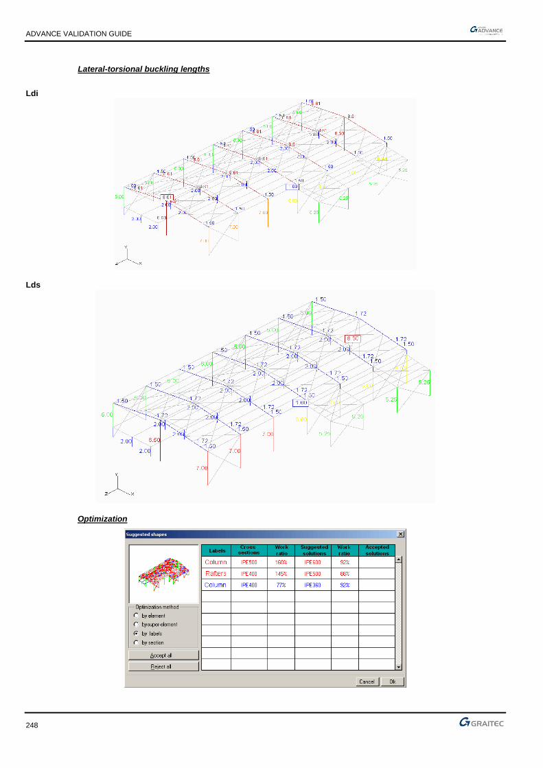
ADVANCE VALIDATION GUIDE
248
Lateral-torsional buckling lengths
Ldi
Lds
Optimization

ADVANCE VALIDATION GUIDE
249
1.90.2.4 Theoretical results
Solver Result name Result description Reference value
CM2 D Maximum displacement (CMCD) [cm] 12.115
CM2 Fx Envelope normal force (CMCFN) Min (Fx) [T] -41.618
CM2 Fx Envelope normal force (CMCFN) Max (Fx) [T] 19.423
CM2 My Envelope bending moment (CMCFN) Min (Mz) [Tm] -57.105
CM2 My Envelope bending moment (CMCFN) Max (Mz) [Tm] 55.744
Warning, the Mz bending moment of Effel Structure corresponds to the My bending moment of Advance Design.
Solver Result name Result description Reference value
CM2 Deflection CM deflections on Columns [adm] L / 168 (89%)
CM2 Deflection CM deflections on Rafters [adm] L / 96 (208%)
CM2 Deflection CM deflections on Columns [adm] L / 924 (16%)
CM2 Stress CM stresses on Columns [MPa] 374.67
CM2 Stress CM stresses on Rafters [MPa] 339.74
CM2 Stress CM stresses on Columns [MPa] 180.98
CM2 Lfy Buckling lengths on Columns Lfy [m] 8.02
CM2 Lfz Buckling lengths on Columns Lfz [m] 24.07
CM2 Lfy Buckling lengths on Rafters Lfy [m] 1.72
CM2 Lfz Buckling lengths on Rafters Lfz [m] 20.25
CM2CM2
Lfy Buckling lengths on Columns Lfy [m] 4.20
CM2 Lfz Buckling lengths on Columns Lfz [m] 5.67
Warning, the local axes in Effel Structure are opposite to those in Advance Design.
Solver Result name Result description Reference value
CM2 Ldi Lateral-torsional buckling lengths on Columns Ldi [m] 8.5
CM2 Lds Lateral-torsional buckling lengths on Columns Lds [m] 8.5
CM2 Ldi Lateral-torsional buckling lengths on Rafters Ldi [m] 8.61
CM2 Lds Lateral-torsional buckling lengths on Rafters Lds [m] 1.72
CM2 Ldi Lateral-torsional buckling lengths on Columns Ldi [m] 2
CM2 Lds Lateral-torsional buckling lengths on Columns Lds [m] 2
Solver Result name Result description Rate (%) Final section
CM2 Work ratio IPE500 columns - section optimization [adm] 1.59 IPE600
CM2 Work ratio IPE400 rafters - section optimization [adm] 1.45 IPE500
CM2 Work ratio IPE400 columns - section optimization [adm] 0.77 IPE360
1.90.3 Calculated results
Result name Result description Value Error
D Maximum displacement (CMCD) [cm] 12.138 cm 0.19%
Fx Envelope normal force (CMCFN) Min (Fx) [T] -41.627 T -0.02%
Fx Envelope normal force (CMCFN) Max (Fx) [T] 19.4736 T 0.26%
My Envelope bending moment (CMCFN) Min (Mz)[Tm] -57.113 T*m -0.01%
My Envelope bending moment (CMCFN) Max (Mz) [Tm] 55.7624 T*m 0.03%
Deflection CM deflections on Columns [adm] 167.595 Adim. -0.24%
Deflection CM deflections on Rafters [adm] 96.0768 Adim. 0.08%
Deflection CM deflections on Columns [adm] 925.218 Adim. 0.13%
Stress CM stresses on Columns [MPa] 374.504 MPa -0.04%

ADVANCE VALIDATION GUIDE
250
Stress CM stresses on Rafters [MPa] 347.517 MPa 2.29%
Stress CM stresses on Columns [MPa] 180.65 MPa -0.18%
Lfy Buckling lengths on Columns Lfy [m] 7.96718 m -0.66%
Lfz Buckling lengths on Columns Lfz [m] 24.0693 m 0.00%
Lfy Buckling lengths on Rafters Lfy [m] 1.72255 m 0.15%
Lfz Buckling lengths on Rafters Lfz [m] 20.2452 m -0.02%
Lfy Buckling lengths on Columns Lfy [m] 4.19567 m -0.10%
Lfz Buckling lengths on Columns Lfz [m] 5.67211 m 0.04%
Ldi Lateral-torsional buckling lengths on Columns Ldi [m] 8.5 m 0.00%
Lds Lateral-torsional buckling lengths on Columns Lds [m]
8.5 m 0.00%
Ldi Lateral-torsional buckling lengths on Rafters Ldi [m] 8.61187 m 0.02%
Lds Lateral-torsional buckling lengths on Rafters Lds [m] 8.61187 m 0.02%
Ldi Lateral-torsional buckling lengths on Columns Ldi [m] 2 m 0.00%
Lds Lateral-torsional buckling lengths on Columns Lds [m]
2 m 0.00%
Work ratio IPE500 columns - section optimization [adm] 1.59363 Adim. 0.23%
Work ratio IPE400 rafters - section optimization [adm] 1.4788 Adim. 1.99%
Work ratio IPE400 columns - section optimization [adm] 0.768724 Adim. -0.17%

ADVANCE VALIDATION GUIDE
251
1.91 CM66 (steel design) - France: Design of a 2D portal frame (03-0207SSLLG_CM66)
Test ID: 2523
Test status: Passed
1.91.1 Description
Verifies the steel calculation results (displacement at ridge, normal forces, bending moments, deflections, stresses, buckling lengths, lateral torsional buckling lengths and cross section optimization) for a 2D metallic portal frame, according to CM66.
1.91.2 Background
1.91.2.1 Model description
■ Calculation model: 2D metallic portal frame.
► Column section: IPE500
► Rafter section: IPE400
► Base plates: hinged.
► Portal frame width: 20m
► Columns height: 6m
► Portal frame height at the ridge: 7.5m
■ Load case:
► Permanent loads: 150 kg/m on the roof + elements self weight.
► Usage overloads: 800 kg/ml on the roof
■ Mesh density: 1m
Model preview
Combinations
Code Numbers Type Title
CMP 1 Static Permanent load + self weight
CMS 2 Static Usage overloads
CMCFN 101 Comb_Lin 1.333P
CMCFN 102 Comb_Lin 1.333P+1.5S
CMCFN 103 Comb_Lin P+1.5S
CMCD 104 Comb_Lin P+S

ADVANCE VALIDATION GUIDE
252
1.91.2.2 Effel Structure Results
Ridge displacements (combination 104)
Diagram of normal force envelope
Envelope of bending moments diagram

ADVANCE VALIDATION GUIDE
253
1.91.2.3 Effel Expert CM results
Main hypotheses
For columns
■ Deflections: 1/150
Envelopes deflections calculation.
■ Buckling: XY plane: Automatic calculation of the structure on fixed nodes
XZ plane: Automatic calculation of the structure on fixed nodes
Ka-Kb Method
■ Lateral-torsional buckling: Ldi automatic calculation: no restraints
Lds imposed value: 2 m
For the rafters
■ Deflections: 1/200
Envelopes deflections calculation.
■ Buckling: XY plane: Automatic calculation of the structure on fixed nodes
XZ plane: Automatic calculation of the structure on fixed nodes
Ka-Kb Method
■ Lateral-torsional buckling: Ldi automatic calculation: No restraints
Lds imposed value: 1.5m
Optimization criteria
■ Work ratio optimization between 90 and 100%
■ Labels optimization (on Advance Design templates)
Deflection verification
Ratio
CM Stress diagrams
Work ratio

ADVANCE VALIDATION GUIDE
254
Stresses
Buckling lengths
Lfy
Lfz
Lateral-torsional buckling lengths
Ldi

ADVANCE VALIDATION GUIDE
255
Lds
Optimization
1.91.2.4 Theoretical results
Solver Result name Result description Reference value
CM2 D Displacement at the ridge [cm] 9.36
CM2 Fx Envelope normal forces on Columns (min) [T] -15.77
CM2 Fx Envelope normal forces on Rafters (max) [T] -1.02
CM2 My Envelope bending moments on Columns (min) [T.m] -42.41
CM2 My Envelope bending moments on Rafters (max) [T.m] 42.41
CM2 Deflection CM deflections on Columns [%] L / 438 (34%)
CM2 Deflection CM deflections on Rafters [%] L / 111 (180%)
CM2 Stress CM stresses on Columns [MPa] 230.34
CM2 Stress CM stresses on Rafters [MPa] 458.38
CM2 Lfy Buckling lengths on Columns - Lfy [m] 5.84
CM2 Lfz Buckling lengths on Columns - Lfz [m] 6
CM2 Lfy Buckling lengths on Rafters - Lfy [m] 7.08
CM2 Lfz Buckling lengths on Rafters - Lfz [m] 10.11
Warning, the local axes in Effel Structure have different orientation in Advance Design.
Solver Result name Result description Reference value
CM2 Ldi Lateral-torsional buckling lengths on Columns Ldi [m] 6
CM2 Lds Lateral-torsional buckling lengths on Columns Lds [m] 2
CM2 Ldi Lateral-torsional buckling lengths on Rafters Ldi [m] 10.11
CM2 Lds Lateral-torsional buckling lengths on Rafters Lds [m] 1.5

ADVANCE VALIDATION GUIDE
256
Solver Result name Result description Rate (%) Final section
CM2 Work ratio IPE500 columns - section optimization 98 IPE500
CM2 Work ratio IPE400 rafters - section optimization 195 IPE550
1.91.3 Calculated results
Result name Result description Value Error
D Displacement at the ridge [cm] 9.36473 cm 0.05%
Fx Envelope normal forces on Columns (min) [T] -15.7798 T -0.06%
Fx Envelope normal forces on Rafters (max) [T] -1.0161 T 0.38%
My Envelope bending moments on Columns (min) [Tm] 42.4226 T*m 0.03%
My Envelope bending moments on Rafters (max) [Tm] 42.4226 T*m 0.03%
Deflection CM deflections on Columns [adm] 438.077 Adim. 0.02%
Deflection CM deflections on Rafters [adm] 111.325 Adim. 0.29%
Stress CM stresses on Columns [adm] 230.331 MPa 0.00%
Stress CM stresses on Rafters [adm] 458.367 MPa 0.00%
Lfy Buckling lengths on Columns - Lfy [m] 6 m 0.00%
Lfz Buckling lengths on Columns - Lfz [m] 5.84401 m 0.07%
Lfy Buckling lengths on Rafters - Lfy [m] 10.1119 m 0.02%
Lfz Buckling lengths on Rafters - Lfz [m] 7.07904 m -0.01%
Ldi Lateral-torsional buckling lengths on Columns Ldi [m] 6 m 0.00%
Lds Lateral-torsional buckling lengths on Columns Lds [m] 2 m 0.00%
Ldi Lateral-torsional buckling lengths on Rafters Ldi [m] 10.1119 m 0.02%
Lds Lateral-torsional buckling lengths on Rafters Lds [m] 1.5 m 0.00%
Work ratio IPE500 columns - section optimization [adm] 0.980131 Adim. 0.01%
Work ratio IPE400 rafters - section optimization [adm] 1.9505 Adim. 0.03%

ADVANCE VALIDATION GUIDE
257
1.92 BAEL 91 (concrete design) - France: Design of a concrete floor with an opening (03-0208SSLLG_BAEL91)
Test ID: 2524
Test status: Passed
1.92.1 Description
Verifies the displacements, bending moments and reinforcement results for a 2D concrete slab with supports and punctual loads.
1.92.2 Background
1.92.2.1 Model description
■ Calculation model: 2D concrete slab.
► Slab thickness: 20 cm
► Slab length: 20m
► Slab width: 10m
► The supports (punctual and linear) are considered as hinged.
► Supports positioning (see scheme below)
► 1,50m*2,50m opening => see positioning on the following scheme
■ Materials:
► Concrete B25
► Young module: E= 36000 MPa
■ Load case:
► Permanent loads: 100 kg/m2
► Permanent loads: 200 kg/ml around the opening
► Punctual loads of 2T in permanent loads (see the following definition)
► Usage overloads: 250 kg/m2
■ Mesh density: 0.5 m
Slab geometry

ADVANCE VALIDATION GUIDE
258
Support positions
Positions of punctual loads
Global loading overview

ADVANCE VALIDATION GUIDE
259
Load Combinations
Code Numbers Type Title
BAGMAX 1 Static Permanent loads + self weight
BAQ 2 Static Usage overloads
BAELS 101 Comb_Lin Gmax+Q
BAELU 102 Comb_Lin 1.35Gmax+1.5Q
1.92.2.2 Effel Structure Results
SLS max displacements (load combination 101)
Mx bending moment for ULS load combination

ADVANCE VALIDATION GUIDE
260
My bending moment for ULS load combination
Mxy bending moment for ULS load combination
1.92.2.3 Effel RC Expert Results
Main hypothesis
■ Top and bottom concrete covers: 3 cm
■ Slightly dangerous cracking
■ Concrete B25 => Fc28= 25 MPa
■ Reinforcement calculation according to Wood method.
■ Calculation starting from non averaged forces.

ADVANCE VALIDATION GUIDE
261
Axi reinforcements
Ayi reinforcements
Axs reinforcements

ADVANCE VALIDATION GUIDE
262
Ays reinforcements
1.92.2.4 Theoretical results
Solver
Result name
Result description Reference value
CM2 D Max displacement for SLS (load combination 101) [cm] 0.176
CM2 Myy Mx and My bending moments for ULS (load combination 102) Max(Mx) [kN.m] 25.20
CM2 Myy Mx and My bending moments for ULS (load combination 102) Min(Mx) [kN.m] -15.71
CM2 Mxx Mx and My bending moments for ULS (load combination 102) Max(My) [kN.m] 31.17
CM2 Mxx Mx and My bending moments for ULS (load combination 102) Min(My) [kN.m] -18.79
CM2 Mxy Mx and My bending moments for ULS (load combination 102) Max (Mxy) [kN.m] 10.26
CM2 Mxy Mx and My bending moments for ULS (load combination 102) Min (Mxy) [kN.m] -10.14
CM2 Axi Theoretic reinforcements Axi [cm2] 3.84
CM2 Axs Theoretic reinforcements Axs [cm2] 3.55
CM2 Ayi Theoretic reinforcements Ayi [cm2] 3.75
CM2 Ays Theoretic reinforcements Ays [cm2] 4.53
These values are obtained from the maximum values from the mesh.
1.92.3 Calculated results
Result name Result description Value Error
D Max displacement for SLS (load combination 101) [cm] 0.174641 cm -0.77%
Myy Mx and My bending moments for ULS (load combination 102) Max(Mx) [kNm]
25.2594 kN*m 0.24%
Myy Mx and My bending moments for ULS (load combination 102) Min(Mx) [kNm]
-15.6835 kN*m 0.17%
Mxx Mx and My bending moments for ULS (load combination 102) Max(My) [kNm]
31.2449 kN*m 0.24%
Mxx Mx and My bending moments for ULS (load combination 102) Min(My) [kNm]
-18.7726 kN*m 0.09%
Mxy Mx and My bending moments for ULS (load combination 102) Max (Mxy) [kNm]
-10.1558 kN*m 1.02%
Mxy Mx and My bending moments for ULS (load combination 102) Min (Mxy) [kNm]
10.2508 kN*m 1.09%
Axi Theoretic reinforcements Axi [cm2] 3.83063 cm² -0.24%
Axs Theoretic reinforcements Axs [cm2] 3.629 cm² 2.23%
Ayi Theoretic reinforcements Ayi [cm2] 3.72879 cm² -0.57%
Ays Theoretic reinforcements Ays [cm2] 4.61909 cm² 1.97%

ADVANCE VALIDATION GUIDE
263
1.93 Verifying the displacement results on linear elements for vertical seism (TTAD #11756)
Test ID: 3442
Test status: Passed
1.93.1 Description
Verifies the displacements results on an inclined steel bar for vertical seism according to Eurocodes 8 localization and generates the corresponding report.
The steel bar has a rigid support and IPE100 cross section and is subjected to self weight and seism load on Z direction (vertical).
1.94 Generating planar efforts before and after selecting a saved view (TTAD #11849)
Test ID: 3454
Test status: Passed
1.94.1 Description
Generates efforts for all planar elements before and after selecting the third saved view.
1.95 Verifying constraints for triangular mesh on planar elements (TTAD #11447)
Test ID: 3460
Test status: Passed
1.95.1 Description
Performs the finite elements calculation, verifies the stresses for triangular mesh on a planar element and generates a report for planar elements stresses in neutral fiber.
The planar element is 20 cm thick, C20/25 material with a linear rigid support. A linear load of 30.00 kN is applied on FX direction.
1.96 Verifying forces for triangular meshing on planar element (TTAD #11723)
Test ID: 3463
Test status: Passed
1.96.1 Description
Performs the finite elements calculation, verifies the forces for triangular meshing on a planar element and generates a report for planar elements forces by load case.
The planar element is a square shell (5 m) with a thickness of 20 cm, C20/25 material with a linear rigid support. A linear load of -10.00 kN is applied on FZ direction.
1.97 Verifying stresses in beam with "extend into wall" property (TTAD #11680)
Test ID: 3491
Test status: Passed
1.97.1 Description
Verifies the results on two concrete beams which have the "Extend into the wall" option enabled. One of the beams is connected to 2 walls on both sides and one with a wall and a pole. Generates the linear elements forces by elements report.
ADVANCE VALIDATION GUIDE
264
1.98 Verifying diagrams after changing the view from standard (top, left,...) to user view (TTAD #11854)
Test ID: 3539
Test status: Passed
1.98.1 Description
Verifies the results diagrams display after changing the view from standard (top, left,...) to user view.
1.99 Verifying forces results on concrete linear elements (TTAD #11647)
Test ID: 3551
Test status: Passed
1.99.1 Description
Verifies forces results on concrete beams consisting of a linear element and on beams consisting of two linear elements. Generates the linear elements forces by load case report.
1.100 Generating results for Torsors NZ/Group (TTAD #11633)
Test ID: 3594
Test status: Passed
1.100.1 Description
Performs the finite elements calculation on a complex concrete structure with four levels. Generates results for Torsors NZ/Group. Verifies the legend results.
The structure has 88 linear elements, 30 planar elements, 48 windwalls, etc.
1.101 Verifying Sxx results on beams (TTAD #11599)
Test ID: 3595
Test status: Passed
1.101.1 Description
Performs the finite elements calculation on a complex model with concrete, steel and timber elements. Verifies the Sxx results on beams. Generates the maximum stresses report.
The structure has 40 timber linear elements, 24 concrete linear elements, 143 steel elements. The loads applied on the structure: dead loads, live loads, snow loads, wind loads and temperature loads (according to Eurocodes).
1.102 EC8 / NF EN 1998-1 - France: Verifying the level mass center (TTAD #11573, TTAD #12315)
Test ID: 3609
Test status: Passed
1.102.1 Description
Performs the finite elements calculation on a model with two planar concrete elements with a linear support. Verifies the level mass center and generates the "Excited total masses" and "Level modal mass and rigidity centers" reports.
The model consists of two planar concrete elements with a linear fixed support. The loads applied on the model are: self weight, a planar live load of -1 kN and seism loads according to French standards of Eurocodes 8.

ADVANCE VALIDATION GUIDE
265
1.103 Verifying diagrams for Mf Torsors on divided walls (TTAD #11557)
Test ID: 3610
Test status: Passed
1.103.1 Description
Performs the finite elements calculation and verifies the results diagrams for Mf torsors on a high wall divided in 6 walls (by height).
The loads applied on the model: self weight, two live load cases and seism loads according to Eurocodes 8.
1.104 Verifying results on punctual supports (TTAD #11489)
Test ID: 3693
Test status: Passed
1.104.1 Description
Performs the finite elements calculation and generates the punctual supports report, containing the following tables: "Displacements of point supports by load case", "Displacements of point supports by element", "Point support actions by load case", "Point support actions by element" and "Sum of actions on supports and nodes restraints".
The structure consists of concrete, steel and timber linear elements with punctual supports.
1.105 Generating a report with torsors per level (TTAD #11421)
Test ID: 3774
Test status: Passed
1.105.1 Description
Generates a report with the torsors per level results.
1.106 Verifying nonlinear analysis results for frames with semi-rigid joints and rigid joints (TTAD #11495)
Test ID: 3795
Test status: Passed
1.106.1 Description
Verifies the nonlinear analysis results for two frames with one level. One of the frames has semi-rigid joints and the other has rigid joints.
1.107 Verifying tension/compression supports on nonlinear analysis (TTAD #11518)
Test ID: 4197
Test status: Passed
1.107.1 Description
Verifies the supports behavior when the rigidity has a high value. Performs the finite elements calculation and generates the "Displacements of linear elements by element" report.
The model consists of a vertical linear element (concrete B20, R20*30 cross section) with a rigid punctual support at the base and a T/C punctual support at the top. A large value of the KTX stiffener of the T/C support is defined. Two loads of 500.00 kN are applied.

ADVANCE VALIDATION GUIDE
266
1.108 Verifying tension/compression supports on nonlinear analysis (TTAD #11518)
Test ID: 4198
Test status: Passed
1.108.1 Description
Verifies the behavior of supports with several rigidities fields defined.
Performs the finite elements calculation and generates the "Displacements of linear elements by element" report.
The model consists of a vertical linear element (concrete B20, R20*30 cross section) with a rigid punctual support at the base and a T/C punctual support at the top. A value of 15000.00 kN/m is defined for the KTX and KTZ stiffeners of the T/C support. Two loads of 500.00 kN are applied.
1.109 Verifying the main axes results on a planar element (TTAD #11725)
Test ID: 4310
Test status: Passed
1.109.1 Description
Verifies the main axes results on a planar element.
Performs the finite elements calculation for a concrete wall (20 cm thick) with a linear support. Displays the forces results on the planar element main axes.
1.110 Verifying the display of the forces results on planar supports (TTAD #11728)
Test ID: 4375
Test status: Passed
1.110.1 Description
Performs the finite elements calculation and verifies the display of the forces results on a planar support. The model consists of a concrete vertical element with a planar support.
1.111 Verifying the internal forces results for a simple supported steel beam
Test ID: 4533
Test status: Passed
1.111.1 Description
Performs the finite elements calculation for a horizontal element (S235 material and IPE180 cross section) with two hinge rigid supports at each end. One of the supports has translation restraints on X, Y and Z, the other support has restraints on Y and Z.
Verifies the internal forces My, Fz. Validated according to: Example: 3.1 - Simple beam bending without the stability loss Publication: Steel structures members - Examples according to Eurocodes By: F. Wald a kol.
1.112 Verifying forces on a linear elastic support which is defined in a user workplane (TTAD #11929)
Test ID: 4553
Test status: Passed
1.112.1 Description
Verifies forces on a linear elastic support, which is defined in a user workplane, and generates a report with forces for linear support in global and local workplane.

ADVANCE VALIDATION GUIDE
267
1.113 Verifying torsors on a single story coupled walls subjected to horizontal forces
Test ID: 4804
Test status: Passed
1.113.1 Description
Verifies torsors on a single story coupled walls subjected to horizontal forces
1.114 Calculating torsors using different mesh sizes for a concrete wall subjected to a horizontal force (TTAD #13175)
Test ID: 5088
Test status: Passed
1.114.1 Description
Calculates torsors using different mesh sizes for a concrete wall subjected to a horizontal force.

ADVANCE VALIDATION GUIDE
268
1.115 Verifying results of a steel beam subjected to dynamic temporal loadings (TTAD #14586)
Test ID: 5853
Test status: Passed
1.115.1 Description
Verifies a double-end fixed steel beam subjected to harmonic concentrated loadings.
2 Hz and 3 Hz excitation frequencies are studied.
1.115.2 Background
The harmonic response of a steel beam fixed at both ends is studied. The beam contains 8 elements having the same length and identical characteristics. Harmonic concentrated loadings (a vertical load and a bending moment) are applied in the middle of the beam. Two excitation frequencies are studied: 2.0 and 3.0 Hz.
1.115.2.1 Model description
■ Reference: NE/Nastran V8;
■ Analysis type: modal analysis;
■ Element type: linear.
Units
I. S.
Geometry
Below are described the beam cross section characteristics:
■ Beam length: L = 16 m,
■ Square shaped cross section: b = 0.05 m,
■ Section area: A = 0.06 m2,
■ Flexion inertia moment about the y (or z) axis: I = 0.0001 m4.
Materials properties
■ Longitudinal elastic modulus: E = 2.1 x 10¹¹ N/m2,
■ Poisson coefficient: = 0.3,
■ Density: = 7850 kg/m3.
Boundary conditions
■ Outer:
► Fixed support at start point (x = 0),
► Fixed support at end point (x = 16.00).
■ Inner: None.
Loading
■ External:
► Point load at x=8: P = Fz = -50 000 sin (2π f t) N

ADVANCE VALIDATION GUIDE
269
► Bending moment at x=8: M = My = 10000 sin (2π f t) Nm
■ Internal: None.
1.115.2.2 Harmonic response from NE/Nastran V8
Reference solution
Considering a natural frequency (modal) analysis for a double-end fixed beam, the first four natural frequencies can be determined using the following formula:
A
IE
Lf n
n
=
2
2
2
The modal response is determined considering 14 modes.
The first four mode shapes and their frequencies are:
12 = 22.37 → f1 = 2.937 Hz
22 = 61.67 → f2 = 8.095 Hz
32 = 120.9 → f3 = 15.871 Hz
42 = 199.8 → f4 = 26.228 Hz
The vertical reference displacement is calculated in the middle of the beam at x = 8 m.
Software NE/NASTRAN 8.0
Vertical maximum displacement (f = 2 Hz) in the middle of the beam
0.155 m
Vertical maximum displacement (f = 3 Hz) in the middle of the beam
2.266 m
Response in the middle of the beam with f = 2 Hz

ADVANCE VALIDATION GUIDE
270
Response in the middle of the beam with f = 3 Hz
Finite elements modeling
■ Linear element: beam, imposed mesh
■ 9 nodes,
■ 8 linear elements.
1.115.2.3 Reference results
Result name Result description Reference value
Deformed – D Vertical maximum displacement in the middle of the beam (2 Hz) [m]
0.155 m
Deformed – D Vertical maximum displacement in the middle of the beam (3 Hz) [m]
2.266 m
1.115.3 Calculated results
Result name Result description Value Error
D Vertical maximum displacement in the middle of the beam (2 Hz)
15.3783 cm -0.7852 %
D Vertical maximum displacement in the middle of the beam (3 Hz)
211.41 cm -6.7034 %

ADVANCE VALIDATION GUIDE
271
1.116 Verifying a simply supported concrete slab subjected to temperature variation between top and bottom fibers
Test ID: 6239
Test status: Passed
1.116.1 Description
Verifies a simply supported concrete slab subjected to a variation of temperature (8 Celsius degrees outside and 22 Celsius degrees inside).
In this project, global Z axis is oriented downwards.

ADVANCE VALIDATION GUIDE
272
1.117 FEM Results - United Kingdom: Simply supported laterally restrained (from P364 Open Sections Example 2)
Test ID: 6327
Test status: Passed
1.117.1 Description
The 533x210x92 UKB in S275 beam is fully laterally restrained along its length and pinned supports, includes a UDL and point load at the centre.
1.117.2 Background
1.117.2.1 Model description
Reference: SCI PUBLICATION P364, Steel Building Design: Worked Examples - Open Sections. In accordance with Eurocodes and the UK National Annexes, Example 2 - Simply supported laterally restrained beam
■ Analysis type: static linear (plane problem),
■ Element type: linear,
The beam shown in the figure below is fully laterally restrained along its length and has bearing lengths of 50 mm at the unstiffened supports and 75 mm under the point load. Design the beam in S275 steel for the loading shown below.
The design aspects covered in this example are:
■ Calculation of design values of actions for ULS and SLS,
■ Cross section classification,
■ Cross sectional resistance:
► Shear buckling,
► Shear,
► Bending moment,
■ Resistance of web to transverse forces,
■ Vertical deflection of beam at SLS.
Units
Metric System
Geometry
Below are described the column cross section characteristics:
■ Depth: h= 533.1 mm
■ Width: b= 209.3 mm
■ Flange thickness: tf = 15.6 mm
■ Root radius: r= 12.7 mm
■ Depth between flange fillets: d= 476.5 mm
■ Second moment of area, y-y axis: Iy = 552000000 mm4
■ Plastic modulus, y-y ax: Wpl,y = 23600000 mm4
■ Section area: A= 11700 mm2
■ Modulus of elasticity: E = 210000 N/mm2

ADVANCE VALIDATION GUIDE
273
Materials properties
For buildings that will be built in the UK, the nominal values of the yield strength (fy) and the ultimate strength (fu) for structural steel should be those obtained from the product standard. Where a range is given, the lowest nominal value should be used.
For S275 steel and t ≤ 16 mm
■ Yield strength: fy = ReH = 275 N/mm2
1.117.2.2 Shear resistance
Verify that:
VEd
Vc,Rd≤ 1.0
For plastic design, 𝑉𝑐,𝑅𝑑 is the design plastic shear resistance (𝑉𝑝𝑙,𝑅𝑑).
Vc,Rd = Vpl,Rd =Av(fy/√3)
γM0
𝐴𝑣 is the shear area and is determined as follows for rolled I and H sections with the load applied parallel to the web.
Av = A − 2btf + tf(tw + 2r) = 117 × 102 − (2 × 209.3 × 15.6) + 15.6 × (10.1 + (2 × 12.7)) = 7187.5 mm2
ηhwtw = 1.0 × 5.109 × 10.1 = 5069.2 mm2
Therefore,
Av = 5723.6 mm2
The design plastic shear resistance is:
Vc,Rd = Av(fy/√3)
γM0=
5723.6 × (275/√3)
1.0× 10−3 = 909 kN
Maximum design shear VEd = 269.5 kN
VEd
Vc,Rd=
269.5
909= 0.30 < 1.0
Therefore the shear resistance of the section is adequate.
1.117.2.3 Reference results
Result name Result description Reference value
Steel Strength - Work ratio - Fz Shear Resistance 30%
1.117.3 Calculated results
Result name Result description Value Error
Work ratio - Fz Work ratio - Fz 29.6673 % -1.1090 %

ADVANCE VALIDATION GUIDE
274
1.118 Verifying the correct use of symmetric steel cross sections (eg. IPE300S)
Test ID: 6350
Test status: Passed
1.118.1 Description
This test is verifying if the symmetric steel cross sections are sent correctly, with the inversed cross section characteristics, to the CM2 engine.
1.119 Temperature load: SD frame with elements under tempertature gradient, applied on separate systems
Test ID: 6362
Test status: Passed
1.119.1 Description
The purpose of this test is check the displacements values of a node (hinge node) on a Static determined frame.
All 3 linear elements are subjected to a load from a temperature applies with different gradient values.
All 3 temperature load cases are applied on each element, using the List option from the temperature load case.
1.120 Verifying displacements of a prestressed cable structure with results presented in Tibert, 1999.
Test ID: 6365
Test status: Passed
1.120.1 Description
The model contains 12 prestressed cable elements subjected to a small uniform self-weight and concentrated loads at each cable intersection point.
Note that the cable net is not in equilibrium under its assumed initial configuration.
The displacement at the cable intersection points under the four point loads is compared with results presented in Tibert, 1999.
1.121 Checks the bending moments in the central node of a steel frame with two beams having a rotational stiffness of 42590 kN/m.
Test ID: 6381
Test status: Passed
1.121.1 Description
ECCS-Manual Design of Steel Structures to EC3(2010) L.S da Silva, R Simoes H Gervasio.(page 79-Example 2.2), point a.
It checks the bending moments in the central node of a steel frame with two beams having a rotational stiffness of 42590 kN/m.

ADVANCE VALIDATION GUIDE
275
1.122 Verifying the response spectrum analysis results for a 2D frame
Test ID: 6420
Test status: Passed
1.122.1 Description
The test verifies the response spectrum analysis method results for 2D frame. The masses are lumped at the middle of each rigid element.
1.122.2 Background
Two storey structure shown in the figure below is subjected to Montreal response spectrum. Using RSA method the test verifies the probable maximum displaced shape of the structure, the maximum shear in the second floor as well as the maximum shear at the base using the SRSS combination. It is assumed that the damping is 5% in each mode of vibration.
Gravity g=9.81m/s2
1.122.2.1 Model description
■ Analysis type: Dynamic - 2D problem
■ Elements type: linear and masses
■ Modal analysis: The masses used to calculate the lateral first two modes of the structures are defined by only point masses. An imposed seism damping of 5%.
■ The following load case is used:
► Dead load (category D): Self weight
Masses: M1=6.89T; M2=3.45T
Units
Metric System

ADVANCE VALIDATION GUIDE
276
Geometry
Cross sections:
■ Columns Level1: C164.88,
■ Columns Level2: C143.35,
■ Horizontal members: RIGID,
Lengths:
■ Columns height: 5m,
Materials properties
Reinforced concrete Con040(24) is used. The following characteristics are used in relation to this material:
■ Specified compressive strength of concrete f’c=40MPa,
■ Specified yield strength of non-restressed reinforcement or anchor steel fy=500MPa,
■ Longitudinal elastic modulus: E=29602MPa
■ Transverse rigidity: G=12334.17MPa
■ Poisson’s ratio: ν=0.2
■ Density: 2.45T/m3
Boundary conditions
The boundary conditions are described below:
■ Outer:
► All the columns are fixed at their base
■ Inner: None.
Loading
The frame is subjected the following load combination:
■ The ultimate limit state (ULS) combination is: Cmax = 1 x D
1.122.2.2 Reference results in calculating
Reference solution
a) Spectral responses calculation:
The relative displacement spectral response values i
DS and the spectral acceleration i
AS corresponding to each
mode are obtained from the Response spectrum NBCC2010 of Montreal region (soil C, damping 5%).
The modal analysis of this structure gives :
sT
sT
600.02
231.12
2
2
1
1
==
==
Therefore the spectral values are:
Mode T(s) Sa (g) Sv=Sa/ω (m/s) SD=Sv/ ω (m)
1 1.235 0.119 0.228 0.045
2 0.600 0.300 0.281 0.027

ADVANCE VALIDATION GUIDE
277
b) Maximum displacement values for each DDOF:
The maximal displacement for ach DDOF is given by:
jjDj
jASαx
)(max =
With j are the participation factors of mode j:
j
Tj
jM
rMAα =
jM , the generalized mass calculated for each mode:
jTjj AMAM =
=
838.1
11A
;
−=
089.1
12A
mkNsM /823.18838.1
1
5.30
07838.11 2
1 =
=
mNsM /150.11089.1
1
5.30
07089.11 2
2 =
−
−=
Thereby:
714.01
1
5.30
07838.11
823.18
11 =
=α
285.01
1
5.30
07089.11
150.11
12 =
−=α
1= iα
)(059.0
0321.0
838.1
1045.0714.0
1max2
1max1 m
x
x
=
=
)(0084.0
0077.0
089.1
1027.0285.0
2max2
2max1 m
x
x
−=
−=
c) Estimation of maximum modal forces at each level and modal shear forces at the base:
jjxKQ maxmax =
;
jAjj
jSαMV
2max =
;
Mode1:
kNQ
Q
=
−
−=
38.5
85.5
059.0
0321.0
200200
2005501
max2
1max1
kNVbase 202.1181.9119.0714.0823.18 21max ==
Mode2:
kNQ
Q
−=
−
−
−=
22.3
92.5
0084.0
0077.0
200200
2005502
max2
2max1
kNVbase 75.281.93.0285.0150.11 22max ==

ADVANCE VALIDATION GUIDE
278
d) Estimation of maximum responses by statistical combination of the maximum modal responses (SRSS):
Maximum modal responses are combined with the relatively simple statistical method SRSS:
2 ; 1 ;2
max
)2(2
max
)1(max , =
+
= ixxx iii
( ) ( ) ;2
max22
max1
max ase, VVVb +=
Maximal displacements:
)(059.0
033.0
0084.0059.0
0077.00321.022
22
max2
max1m
x
x
=
+
+=
Maximal shear at the base:
( ) ( ) ;535.1175.2202.1122
max ase, kNVb =+=
Finite elements modeling
■ Linear element: S beam, rigid;
■ 8 nodes,
■ 6 linear element.
■ 2 point supports

ADVANCE VALIDATION GUIDE
279
1.122.2.3 Reference results
Result name Result description Reference value
x1max Maximal displacement of the first DDOF 33.01mm
X2max Maximal displacement of the second DDOF 59.59mm
Vbase,max Maximum base shear of the response spectrum analysis 11.535kN

ADVANCE VALIDATION GUIDE
280
1.123 Verifying the ultimate factored gravity loads acting on elements of a structure
Test ID: 6421
Test status: Passed
1.123.1 Description
The test verifies the load combination generator according to of the National Building Code of Canada 2010. The ultimate factored gravity loads acting on elements of a structure are evaluated
1.123.2 Background
A building consists of two flat slabs supported by columns and concrete walls (acting also as lateral supports) is subjected to gravity loads (dead loads, live loads and snow loads).
The test verifies the calculation of the factored loads and load combinations as defined by NBCC-2010 carried by an interior column of the building and compares the results returned by the program depending on the fine element meshing type of the slab.
1.123.2.1 Model description
■ Analysis type: linear static analysis – 3D problem
■ Elements type: linear, planar
■ Load cases:
Loads acting on the roof:
Dead load (category D): Fz=-3.0kN/m2; Snow load (category S): Fz=-1.84kN/m2;
Loads acting on the floor:
Dead load (category D): Fz=-3.6kN/m2; Live load (category L): Fz=-2.4kN/m2;
Units
Metric System

ADVANCE VALIDATION GUIDE
281
Geometry
■ Cross sections:
Columns: C500 (500x500mm)
Slabs: 200mm thick
Walls: 200mm thick
Materials properties
Concrete Con030(24) is used in this test. The following characteristics are used in relation to this material:
■ Longitudinal rigidity E=26621MPa
■ Transverse rigidity: G=11092.08MPa
■ Poisson’s ratio: ν=0.2
■ Density=2.45T/m3
Boundary conditions
The boundary conditions are described below:
■ The column are fixed at their bases, Restraints: TX, TY, TZ, RX, RY, RZ;
■ Linear rigid support are placed at the base of the supporting walls, Restraints: TX, TY, TZ, RX, RY, RZ;
Loading
The following ultimate load combinations are used in this test:
Case Load Combination
Principal loads Companion loads
1 D4.1 -
2 D25.1 + L5.1 S5.0
3 D25.1 + S5.1 L5.0
Note:
LOAD COMBINATIONS WITHOUT CRANE LOADS FOR ULTIMATE STATES (NBCC2010):
Case Load Combination
Principal loads Companion loads
1 D4.1 -
2 ( D25.1 or D9.0 ) + L5.1 S5.0 or W4.0
3 ( D25.1 or D9.0 ) + S5.1 L5.0 or W4.0
4 ( D25.1 or D9.0 ) + W4.1 L5.0 or S5.0
5 ( D0.1 + E0.1 ) L5.0 + S25.0
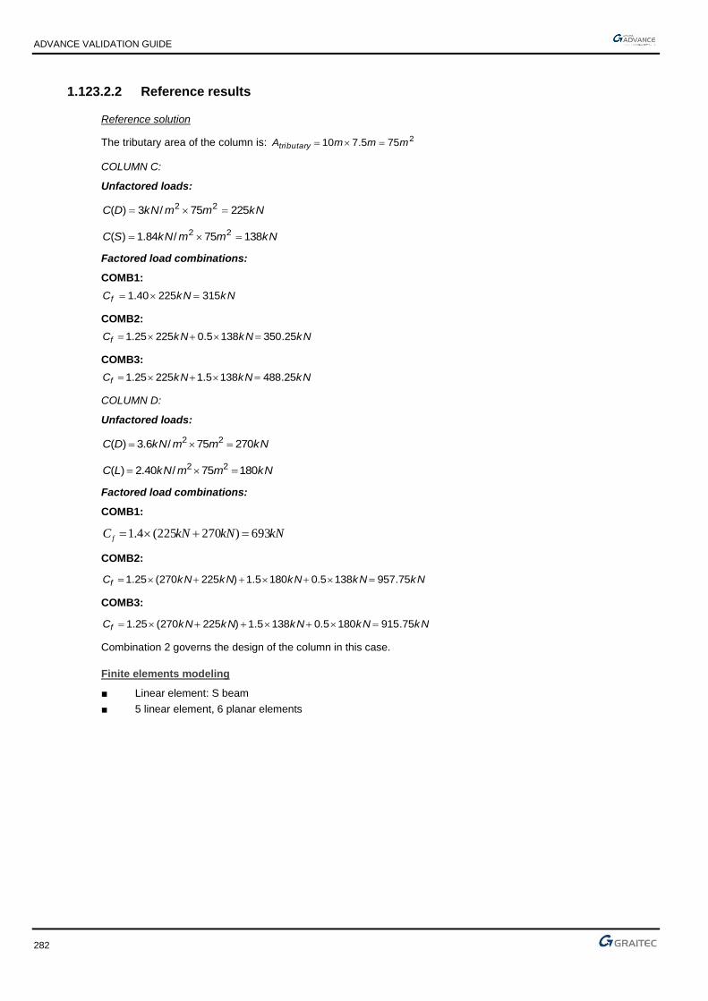
ADVANCE VALIDATION GUIDE
282
1.123.2.2 Reference results
Reference solution
The tributary area of the column is: 2755.710 mmmAtributary ==
COLUMN C:
Unfactored loads:
kNmmkNDC 22575/3)( 22 ==
kNmmkNSC 13875/84.1)( 22 ==
Factored load combinations:
COMB1:
kNkNCf 31522540.1 ==
COMB2:
kNkNkNCf 25.3501385.022525.1 =+=
COMB3:
kNkNkNCf 25.4881385.122525.1 =+=
COLUMN D:
Unfactored loads:
kNmmkNDC 27075/6.3)( 22 ==
kNmmkNLC 18075/40.2)( 22 ==
Factored load combinations:
COMB1:
kNkNkNC f 693)270225(4.1 =+=
COMB2:
kNkNkNkNkNCf 75.9571385.01805.1)225270(25.1 =+++=
COMB3:
kNkNkNkNkNCf 75.9151805.01385.1)225270(25.1 =+++=
Combination 2 governs the design of the column in this case.
Finite elements modeling
■ Linear element: S beam
■ 5 linear element, 6 planar elements

ADVANCE VALIDATION GUIDE
283
Combination 101:
Combination 103:
Combination 106:

ADVANCE VALIDATION GUIDE
284
1.123.2.3 Reference results
Result name Result description Level of the column Reference value
COMB1 Factored axial load Level 2 315.00kN
Level 1 693.00kN
COMB2 Factored axial load Level 2 350.25kN
Level 1 957.75kN
COMB3 Factored axial load Level 2 488.25kN
Level 1 915.75kN

ADVANCE VALIDATION GUIDE
285
1.124 Verifying results for prestressed steel cables (Sxx 10MPa)
Test ID: 6495
Test status: Passed
1.124.1 Description
A reinforced concrete (C25/30) frame with R20*30 cross sections for both columns and the beam is prestressed diagonally with an S235, D5.05 cross section, cable. The reference parameters are the displacement of the upper left corner of the frame (node 21, coord. 0 0 5) and stress Sxx on the cable (linear element no. 4, start end coord. 0 0 5). The prestressed state of the cable is defined as an initial constraint Sxx of 10 MPa.
The reference values are compared with results obtained for an identical model on an independent software.
1.125 Imposed displacement, support settlement (d=30mm)
Test ID: 6496
Test status: Passed
1.125.1 Description
It is given a simple reinforced concrete frame: two beams and one beam. The right side support suffers a settlement of 30mm = an imposed displacement of 30mm is defined. The values for the upper left node displacement, the displaced support displacement and the bending moment in the beam are validated with an independent software.
1.126 Plane strain behavior - dam cross-section supporting earth/water pressure of 0.7 and 1 MPa
Test ID: 6519
Test status: Passed
1.126.1 Description
The model represents a retaining wall behavior under earth/water pressure load. The structure is reduced to a representative cross-section modelled by a plane strain planar element type, made of C25/30 cocrete and fixed at the base. The pressure (0.7 and 1 MPa) acting on the face of the wall is represented by two linear loads: 700 and 1000 kN/m.
The reference values (displacement of planar element report) are compared with results obtained for an identical model on an independent software.
1.127 Spectral/Seismic analysis for rigid diaphragm (membrane) subjected to bidirectional seismic action
Test ID: 6521
Test status: Passed
1.127.1 Description
The test verifies the modal masses and frequencies of the 3D system subjected to bidirectional horizontal seismic action.
The vertical elements are two columns and two shell elements made of C25/30 concrete. The columns have square section of 30x30 cm and the walls have 20 cm thickness with a 5 m height. The columns are fixed at the base while the walls are pinned with linear supports. The slab above the vertical elements is modelled with a load area defined as a rigid diaphragm made of C25/30 concrete with 20 cm thickness. A gravity load uniformly distributed is defined on the rigid diaphragm, with a value of 9.81 kN/m2. The seismic action is defined according to EN 1998-1, having imposed agr/g = 3 and A soil type, using Elastic 1 spectrum. Modal analysis takes into account the masses obtained by combining static loads. Ten modes will be analyzed.

ADVANCE VALIDATION GUIDE
286
1.128 Modal analysis of a structure with “bar” type elements
Test ID: 6534
Test status: Passed
1.128.1 Description
This test verifies results from the modal analysis for a simple tower-shaped structure made from bar linear elements. All linear elements are steel pipes with the same cross-section (D100x5mm) and are defined by using ‘bar’ element type (transferring only axial forces), made of S235 steel.
All four punctual supports are supposed to be pinned. Modal analysis includes 10 modes to be verified. Mass definition is from the self-weight of the elements with no masses eccentricity and 0% imposed damping.
The results to be verified are the frequencies of the first 6 eigen modes and the exited total masses on UX and UY directions. The results are validated with another independent software.
1.128.2 Background
1.128.2.1 Model description
■ 3D structure – linear elements only
■ Element type: Bar
■ Analysis type: Modal analysis
Units
Metric System
Geometry
■ Base length L=4.0 m
■ Base width W=3.0 m
■ Two identical segments with the height 4.0m each
■ Total structure height = 8.0 m
Linear elements
■ Type: bar
■ Cross section:
▪ Circular hollow
▪ Diameter: 100.0 mm
▪ Thickness: 5.0 mm

ADVANCE VALIDATION GUIDE
287
Materials properties
Isotropic material:
■ Mass Density ρ = 7850 kg/m3
■ Young's Modulus E = 210 GPa
■ Poisson's Ratio ν = 0.3
Boundary conditions
■ Punctual supports at 4 points: (0;0;0), (4,0,0), (4,3,0) and (0,3,0)
■ Type: Pinned
■ Coordinate system: Global
Loading
■ None
1.128.2.2 Reference results
Modal analysis assumptions
■ Number of modes: 10
■ Masses definition: from the self-weight
■ Imposed damping: 0%
■ Masses eccentricity: Disabled
Finite elements modeling
■ Number of bars: 32
■ Number of nodes: 12
■ All linear elements are ‘bars’ type
Verified results
Verified results are:
■ Frequencies for first 6 eigen modes
■ Excited total masses (on UX and UY directions)

ADVANCE VALIDATION GUIDE
288
Comparison
Results are compared with results coming from the identical model created and calculated by using another independent FEM software with following assumptions to the Modal analysis:
■ Mass matrix type: Lumped without rotations
■ Active mass directions: X,Y,Z
■ Analysis method: Subspace iteration\
■ Dumping: Not active

ADVANCE VALIDATION GUIDE
289
Reference values:
1.128.2.3 Calculated results
Description Unit AD 2018R2 AD 2019 Difference Reference Difference
Eigen mode 1 frequency Hz 18.89 18.89 0.0% 18.88 0.05%
Eigen mode 2 frequency Hz 23.74 23.74 0.0% 23.74 0.0%
Eigen mode 3 frequency Hz 29.87 29.87 0.0% 29.86 0.03%
Eigen mode 4 frequency Hz 40.34 40.34 0.0% 40.33 0.02%
Eigen mode 5 frequency Hz 69.02 69.02 0.0% 69.00 0.03%
Eigen mode 6 frequency Hz 70.50 70.50 0.0% 70.49 0.01%
Eigen mode 7 frequency Hz 78.97 78.97 0.0% 78.95 0.02%
Eigen mode 8 frequency Hz 89.85 89.85 0.0% 89.84 0.01%
Eigen mode 9 frequency Hz 98.17 98.17 0.0% 98.15 0.02%
Eigen mode 10 frequency Hz 146.09 146.09 0.0% 146.07 0.01%
Excited total masses - UX kg 1358.2 1358.2 0.0% 1358.6 0.03%
Excited total masses - UY kg 1358.2 1358.2 0.0% 1358.6 0.03%
Excited total masses - UZ kg 1358.2 1358.2 0.0% 1358.6 0.03%

ADVANCE VALIDATION GUIDE
290
1.129 Modal analysis of a structure with ”membrane” type element
Test ID: 6535
Test status: Passed
1.129.1 Description
This test verifies results from the modal analysis for a simple 3D frame structure with horizontal rectangular in plan planar element modeled with using membrane elements type. The model consists in a C25/30 concrete 3D structure made of linear S beams and planar "membrane", with triangular mesh type. The punctual supports are considered to be fixed. Modal analysis includes 10 modes to be verified. Mass definition is from the self-weight of the elements with no masses eccentricity and 0% imposed damping. The results to be verified are the frequencies of the first 10 eigen modes and the excited total masses on UX and UY directions.
1.130 Modal analysis of a structure with rigid diaphragm
Test ID: 6536
Test status: Passed
1.130.1 Description
This test verifies results from the modal analysis for a simple 3D frame structure with horizontal rectangular in plane rigid diaphragm . The diaphragm is modelled by the Load area element. The model consists in a 3D structure made of linear S beams and planar "rigid diaphragm", made from C25/30 concrete. Grid with triangles T3 mesh type. The punctual supports are considered to be fixed. Modal analysis includes 10 modes to be verified. Mass definition is from the self-weight of the elements with no masses eccentricity and 0% imposed damping. The results to be verified are the frequencies of the first 10 eigen modes and the exited total masses on UX and UY directions.

ADVANCE VALIDATION GUIDE
291
1.131 Modal analysis of a structure with elastic punctual supports (local coordinate system)
Test ID: 6537
Test status: Passed
1.131.1 Description
This test verifies results from the modal analysis for a simple 3D frame structure with elastic punctual supports. Supports are defined in the local coordinate systems (compatible with connected linear elements). Linear elements are S beam type 20x30 cm cross section made of C25/30 concrete. Punctual elastic supports are defined on points A and B. Seismic damping is set to 0.0% for all directions for both supports. 10 modes will be analyzed with mass definition from self-weight of the elements with 0% imposed damping and no mass eccentricity. Frequencies and excited total masses will be analyzed and compared with reference results obtained by modelling the same structure in another independent software.
1.131.2 Background
1.131.2.1 Model description
■ 3D structure – bending rigid structure
■ Element types: S beam
■ Analysis type: Modal analysis
Units
Metric System
Geometry
2D frame (XZ plane) defined on 3D model.
■ Beam coordinates: (A) 0,0,5; (B) 5,0,3
■ Column coordinates: (B) 5,0,3; (C) 5,0,0
Linear elements
■ Type: S beam
■ section:
▪ Rectangular
▪ Height: 30.0 cm
▪ Width: 20.0 cm

ADVANCE VALIDATION GUIDE
292
Materials properties
Isotropic material (Concrete C25/30):
■ Mass Density ρ = 2500 kg/m3
■ Young's Modulus E = 31475.806 MPa
■ Poisson's Ratio ν = 0.2
Boundary conditions
Punctual elastic supports defined on points A and B.
Seismic damping is set to 0.0% for all directions for both supports.
Point A:
■ Coordinate system: Local (Linear element #1)
■ Stiffness:
▪ KTX 100.0 kN/m
▪ KTY 1000000.0 kN/m
▪ KTZ 0.0 kN/m
▪ KRX 0.0 kNm/deg
▪ KRY 0.0 kNm/deg
▪ KRZ 1000000.0 kNm/deg
Point B:
■ Coordinate system: Local (Linear element #2)
■ Stiffness:
▪ KTX 1000000.0 kN/m
▪ KTY 100.0 kN/m
▪ KTZ 1000000.0 kN/m
▪ KRX 0.0 kNm/deg
▪ KRY 100.0 kNm/deg
▪ KRZ 0.0 kNm/deg

ADVANCE VALIDATION GUIDE
293
Loading
■ None
1.131.2.2 Reference results
Modal analysis assumptions
■ Number of modes: 10
■ Masses definition: from the self-weight
■ Imposed damping: 0%
■ Masses eccentricity: Disabled
Finite elements modeling
■ Number of bars: 2 (s beams)
■ Mesh definition for linear elements set as Automatic with Size = 0.5 m
Verified results
Verified results are:
■ Frequencies for first 10 eigen modes
■ Excited total masses (on UX and UY directions)

ADVANCE VALIDATION GUIDE
294
6 first modes:

ADVANCE VALIDATION GUIDE
295
Comparison
Results are compared with results coming from the identical model created and calculated by using another independent FEM software with following assumptions to the Modal analysis:
■ Mass matrix type: Lumped without rotations
■ Active mass directions: X,Y,Z
■ Analysis method: Subspace iteration\
■ Dumping: Not active
■ To have identical model (when each linear element is meshed with 0.5 m), all elements have generated additional node at equal intervals.
1.131.2.3 Calculated results
Description Unit AD 2018R2 AD 2019 Difference Reference Difference
Eigen mode 1 frequency Hz 2.077 2.077 0.0% 2,077 0.0%
Eigen mode 2 frequency Hz 2.835 2.835 0.0% 2,837 0.1%
Eigen mode 3 frequency Hz 4.484 4.484 0.0% 4,485 0.02%
Eigen mode 4 frequency Hz 8.227 8.227 0.0% 8,254 0.3%
Eigen mode 5 frequency Hz 20.710 20.710 0.0% 20,809 0.5%
Eigen mode 6 frequency Hz 30.326 30.326 0.0% 30,553 0.7%
Eigen mode 7 frequency Hz 54.720 54.720 0.0% 55,240 0.9%
Eigen mode 8 frequency Hz 69.946 69.946 0.0% 71,020 1.5%
Eigen mode 9 frequency Hz 70.383 70.383 0.0% 71,153 1.1%
Eigen mode 10 frequency Hz 93.445 93.445 0.0% 95,823 2.5%
Excited total masses - UX kg 1257.77 1257.77 0.0% 1257.77 0.0%
Excited total masses - UY kg 1257.77 1257.77 0.0% 1257.77 0.0%
Excited total masses - UZ kg 1257.77 1257.77 0.0% 1257.77 0.0%

ADVANCE VALIDATION GUIDE
296
1.132 Modal analysis of a structure with an elastic linear support (local coordinate system)
Test ID: 6539
Test status: Passed
1.132.1 Description
This test verifies results from the modal analysis for a simple 3D frame structure with an elastic linear support. Supports are defined in the local coordinate systems. The model contains a shell element made of S235 steel with a 2.0 cm thickness. Boundary conditions consist in two linear supports: one is a linear elastic at the top of the shell element and the other is pinned at the bottom. 10 modes will be analyzed with mass definition from self-weight. No masses eccentricity. 0% imposed damping. Mesh is defined as Delaunay only Q4 quadrangles. Frequencies for the first 10 modes and excited total masses will be verified and compared with results obtained by modelling the same structure in another independent FEM software.
1.132.2 Background
1.132.2.1 Model description
■ 3D structure – bending rigid structure
■ Element type: Shell
■ Analysis type: Modal analysis
Units
Metric System
Geometry
A rectangular planar element defined on 4 points:
■ (A) 0,0,5; (B) 0,3,5: (C) 5,0,0; (C) 5,3,0
■ Thickness: 2.0 cm
Materials properties
Isotropic material (Steel S235):
■ Mass Density ρ = 7850 kg/m3
■ Young's Modulus E = 210 GPa
■ Poisson's Ratio ν = 0.3
Boundary conditions
Linear elastic support between points A and B:
■ Coordinate system: Local (Plate 1)
■ Stiffness:

ADVANCE VALIDATION GUIDE
297
▪ KTX 10000000.0 kN/m/m
▪ KTY 0.0 kN/m/m
▪ KTZ 100.0 kN/m/m
▪ KRX 0.0 kNm/deg/m
▪ KRY 100.0 kNm/deg/m
▪ KRZ 0.0 kNm/deg/m
Linear rigid support between points C and D:
■ Coordinate system: Local
■ Type: Pin (free RX,RY,RZ, blocked TX,TY,TZ)
Loading
■ None
1.132.2.2 Reference results
Modal analysis assumptions
■ Number of modes: 10
■ Masses definition: from the self-weight
■ Imposed damping: 0%
■ Masses eccentricity: Disabled
Finite elements modeling
■ Number nodes: 105
■ Mesh definition is Global
■ Mesh type: Delaunay, only quadrangles
■ FE size: 0.5 m
Verified results
Verified results are:
■ Frequencies for first 10 eigen modes
■ Excited total masses (on UX, UY and UZ directions)
4 first modes:

ADVANCE VALIDATION GUIDE
298
Comparison
Results are compared with results coming from the identical model created and calculated by using an independent commercial FEM software with following assumptions to the Modal analysis:
■ Mass matrix type: Lumped without rotations
■ Active mass directions: X,Y,Z
■ Analysis method: Subspace iteration
■ Dumping: Not active

ADVANCE VALIDATION GUIDE
299
1.132.2.3 Calculated results
Description Unit AD 2018R2 AD 2019 Reference Difference
Eigen mode 1 frequency Hz 1.304 1.304 1,298 0.5%
Eigen mode 2 frequency Hz 2.370 2.370 2,372 0.1%
Eigen mode 3 frequency Hz 3.231 3.231 3,231 0.0%
Eigen mode 4 frequency Hz 5.364 5.364 5,379 0.3%
Eigen mode 5 frequency Hz 6.511 6.511 6,466 0.7%
Eigen mode 6 frequency Hz 9.684 9.684 9,660 0.2%
Eigen mode 7 frequency Hz 12.102 12.102 11,994 0.9%
Eigen mode 8 frequency Hz 12.336 12.336 12,054 2.3%
Eigen mode 9 frequency Hz 14.767 14.767 14,719 0.3%
Eigen mode 10 frequency Hz 15.755 15.755 15,524 1.5%
Excited total masses - UX kg 3211,5 3211,5 3196,04 0.5%
Excited total masses - UY kg 3211,5 3211,5 3196,04 0.5%
Excited total masses - UZ kg 3211,5 3211,5 3196,04 0.5%

ADVANCE VALIDATION GUIDE
300
1.133 Modal analysis of a structure with planar elastic supports (global coordinate system)
Test ID: 6540
Test status: Passed
1.133.1 Description
This test verifies the modal analysis results for a simple 3D structure with planar elastic supports.
Supports are defined in the global coordinate systems. The model consists in a 2D frame (one horizontal beam and two vertical columns) resting on two square planar elements. The planar elements are defined as a shell while the linear are S beams. The planar elements have 20 cm thickness while the linear have 20x30 cm section, made of C25/30 concrete.
Planar elastic supports are defined under the full area of both planar elements (A and B), having elastic characteristics. Supports are defined in the global coordinate systems. Ten modes will be analyzed having mass definition from selfweight with no eccentricity, with 0% imposed damping. The mesh type is Delaunay Q4 quadrangles with 0.5 m dimension.
Frequencies for the first 10 modes and excited total masses will be analyzed and compared with result obtained by modelling the same structure in another independent FEM software.
1.133.2 Background
1.133.2.1 Model description
■ 3D structure – bending rigid structure
■ Element types: Planar – Shell, Linear – S beams
■ Analysis type: Modal analysis
Units
Metric System
Geometry
A 2D frame (one horizontal beam on two columns) is standing on two square planar elements.
■ Length of beam: 5.0m
■ Height of columns: 3.0 m
■ Width x Length of planar elements: 2.0 x 2.0 m
■ Thickness of planar elements: 20 cm
■ Section of linear elements: Rectangular – width 20cm, height 30 cm

ADVANCE VALIDATION GUIDE
301
Materials properties
The same material for linear and planar elements.
Isotropic material (Concrete C25/30):
■ Mass Density ρ = 2500 kg/m3
■ Young's Modulus E = 31475.806 MPa
■ Poisson's Ratio ν = 0.2
Boundary conditions
Planar elastic supports are defined under full area of both planar elements (A and B).
Parameters for support on the planar element A (under column no. 1):
■ Coordinate system: Global
■ Stiffness:
▪ KTX 100.0 kN/m/m2
▪ KTY 10.0 kN/m/m2
▪ KTZ 10000.0 kN/m/m2
▪ KRX 0.0 kNm/deg/m2
▪ KRY 0.0 kNm/deg/m2
▪ KRZ 100.0 kNm/deg/m2
Parameters for support on the planar element B (under column no. 2):
■ Coordinate system: Global
■ Stiffness:
▪ KTX 100.0 kN/m/m2
▪ KTY 10000.0 kN/m/m2
▪ KTZ 10.0 kN/m/m2
▪ KRX 0.0 kNm/deg/m2
▪ KRY 0.0 kNm/deg/m2
▪ KRZ 100.0 kNm/deg/m2
Loading
■ None
1.133.2.2 Reference results
Modal analysis assumptions
■ Number of modes: 10
■ Masses definition: from the self-weight
■ Imposed damping: 0%

ADVANCE VALIDATION GUIDE
302
■ Masses eccentricity: Disabled
Finite elements modeling
■ Number of linear elements (s beam): 3
■ Number of planar elements (shell): 2
■ Mesh definition is Global
■ Mesh type: Delaunay, only quadrangles
■ FE size: 0.5 m
Verified results
Verified results are:
■ Frequencies for first 10 eigen modes
■ Excited total masses (on UX, UY and UZ directions)
Modes 1 and 2:

ADVANCE VALIDATION GUIDE
303
Modes 3 and 4:
Modes 5 and 6:
Modes 7 and 8:
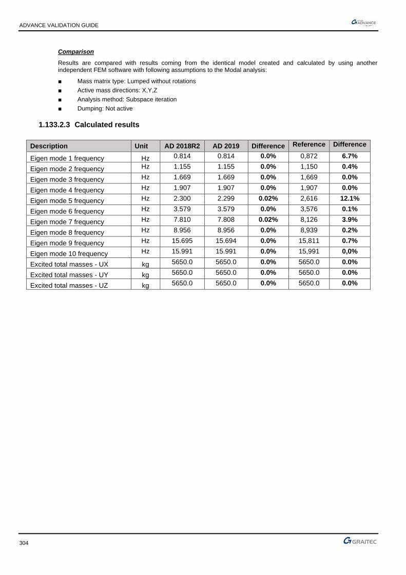
ADVANCE VALIDATION GUIDE
304
Comparison
Results are compared with results coming from the identical model created and calculated by using another independent FEM software with following assumptions to the Modal analysis:
■ Mass matrix type: Lumped without rotations
■ Active mass directions: X,Y,Z
■ Analysis method: Subspace iteration
■ Dumping: Not active
1.133.2.3 Calculated results
Description Unit AD 2018R2 AD 2019 Difference Reference Difference
Eigen mode 1 frequency Hz 0.814 0.814 0.0% 0,872 6.7%
Eigen mode 2 frequency Hz 1.155 1.155 0.0% 1,150 0.4%
Eigen mode 3 frequency Hz 1.669 1.669 0.0% 1,669 0.0%
Eigen mode 4 frequency Hz 1.907 1.907 0.0% 1,907 0.0%
Eigen mode 5 frequency Hz 2.300 2.299 0.02% 2,616 12.1%
Eigen mode 6 frequency Hz 3.579 3.579 0.0% 3,576 0.1%
Eigen mode 7 frequency Hz 7.810 7.808 0.02% 8,126 3.9%
Eigen mode 8 frequency Hz 8.956 8.956 0.0% 8,939 0.2%
Eigen mode 9 frequency Hz 15.695 15.694 0.0% 15,811 0.7%
Eigen mode 10 frequency Hz 15.991 15.991 0.0% 15,991 0,0%
Excited total masses - UX kg 5650.0 5650.0 0.0% 5650.0 0.0%
Excited total masses - UY kg 5650.0 5650.0 0.0% 5650.0 0.0%
Excited total masses - UZ kg 5650.0 5650.0 0.0% 5650.0 0.0%

ADVANCE VALIDATION GUIDE
305
1.134 Modal analysis of a structure with an elastic linear support (global coordinate system)
Test ID: 6541
Test status: Passed
1.134.1 Description
This test verifies results from the modal analysis for a simple 3D frame structure with an elastic linear support. Supports are defined in the global coordinate systems. The model contains a shell element made of S235 steel with a 2.0 cm thickness. Boundary conditions consist in two linear supports: one is a linear elastic at the top of the shell element and the other is pinned at the bottom. 10 modes will be analyzed with mass definition from self-weight. No masses eccentricity. 0% imposed damping. Mesh is defined as Delaunay only Q4 quadrangles. Frequencies for the first 10 modes and excited total masses will be verified and compared with results obtained by modelling the same structure in another independent FEM software.
1.134.2 Background
1.134.2.1 Model description
■ 3D structure – bending rigid structure,
■ Element type: Shell,
■ Analysis type: Modal analysis,
Units
Metric System
Geometry
A rectangular planar element defined on 4 points:
■ (A) 0,0,5; (B) 0,3,5; (C) 5,0,0; (D) 5,3,0;
■ Thickness: 2.00 cm
Materials properties
Isotropic material (Steel S235):
■ Mass Density ρ= 7850 kg/m3,
■ Young's Modulus E= 210 GPa,
■ Poisson's Ratio 𝜈= 0.3,
Boundary conditions
Linear elastic support between points A and B:
■ Coordinate system: Global

ADVANCE VALIDATION GUIDE
306
■ Stiffness:
▪ KTX 100.0 kN/m/m
▪ KTY 0.0 kN/m/m
▪ KTZ 10000000.0 kN/m/m
▪ KRX 0.0 kNm/deg/m
▪ KRY 100.0 kNm/deg/m
▪ KRZ 10000000.0 kNm/deg/m
Linear rigid support between points C and D:
■ Coordinate system: Global
■ Type: Pin (free RX,RY,RZ; blocked TX,TY,TZ)
Loading
■ None
1.134.2.2 Reference results
Modal analysis assumptions
■ Number of modes: 10,
■ Masses definition: from the self-weight,
■ Imposed damping: 0%,
■ Masses eccentricity: Disabled,
Finite elements modeling
■ Number nodes: 105,
■ Mesh definition is Global,
■ Mesh type: Delaunay, only quadrangles,
■ FE size: 0.5 m,
Verified results
Verified results are:
■ Frequencies for first 10 eigen modes,
■ Excited total masses (on UX, UY and UZ directions),
4 first modes:

ADVANCE VALIDATION GUIDE
307
Comparison
Results are compared with results coming from the identical model created and calculated by using another independent FEM software with the following assumptions to the Modal analysis:
■ Mass matrix type: Lumped without rotations,
■ Active mass directions: X,Y,Z,
■ Analysis method: Subspace iteration,
■ Dumping: Not active,

ADVANCE VALIDATION GUIDE
308
1.134.2.3 Calculated results
Description Unit AD 2018R2 AD 2019 Difference Reference Difference
Eigen mode 1 frequency Hz 1.495 1.495 0.0% 1,486 0.6%
Eigen mode 2 frequency Hz 3.431 3.431 0.0% 3,418 0.4%
Eigen mode 3 frequency Hz 4.916 4.916 0.0% 4,836 1.7%
Eigen mode 4 frequency Hz 7.751 7.751 0.0% 7,676 1.0%
Eigen mode 5 frequency Hz 10.455 10.455 0.0% 10,130 3.2%
Eigen mode 6 frequency Hz 13.111 13.111 0.0% 12,969 1.1%
Eigen mode 7 frequency Hz 13.583 13.583 0.0% 13,295 0.9%
Eigen mode 8 frequency Hz 17.186 17.186 0.0% 17,030 2.2%
Eigen mode 9 frequency Hz 18.305 18.305 0.0% 17,359 0.9%
Eigen mode 10 frequency Hz 21.369 21.369 0.0% 20,519 5.4%
Excited total masses - UX kg 3211,5 3211,5 0.0% 3211,5 0.0%
Excited total masses - UY kg 3211,5 3211,5 0.0% 3211,5 0.0%
Excited total masses - UZ kg 3211,5 3211,5 0.0% 3211,5 0.0%

ADVANCE VALIDATION GUIDE
309
1.135 Modal analysis of a structure with releases on beam elements
Test ID: 6542
Test status: Passed
1.135.1 Description
This test verifies results from the modal analysis for a 2D structure with beam linear elements. On ends of selected linear elements total releases are defined. The model consists of a 2D structure – bending rigid structure on plane (XZ) made of beam linear elements. IPE100 cross section S235 steel. The two columns are fixed at the bottom. Linear elements with number 5,6,7 have Ry released and linear element number 9 has Tz released at the top (End1). 10 modes will be analyzed with mass definition from self-weight. No masses eccentricity. 0% imposed damping. Frequencies for the first 10 modes and excited total masses will be verified and compared with results obtained by modelling the same structure in another independent FEM software.
1.135.1.1 Model description
■ 2D structure - bending rigid structure on plane (XZ)
■ Linear element types: Beam
■ Analysis type: Modal analysis
Units
Metric System
Geometry
2D structure on XZ plane - dimensions as on the picture above.
Linear elements
■ Type: Beams
■ Section: IPE100
Materials properties
Isotropic material: Steel S235:
■ Mass Density ρ = 7850 kg/m3
■ Young's Modulus E = 210 GPa
■ Poisson's Ratio ν = 0.3

ADVANCE VALIDATION GUIDE
310
Boundary conditions
■ Punctual supports at the bottom of both columns
■ Type: Fixed (blocked are all 3 available directions: TX, TZ, RY)
■ Coordinate system: Global
Releases
Defined total releases:
■ Ry on both ends of linear elements with number 5,6,7
■ Tz on the top (End1) of the linear element number 9
Loading
■ None
1.135.1.2 Reference results
Modal analysis assumptions
■ Number of modes: 10
■ Masses definition: from the self-weight
■ Imposed damping: 0%
■ Masses eccentricity: Disabled
Finite elements modeling
■ Number of bars: 11 (type: beam)
■ Number of nodes: 8
■ Mesh on all linear elements is set as Automatic with the Number set to 10.

ADVANCE VALIDATION GUIDE
311
Verified results
Verified results are:
■ Frequencies for first 10 eigen modes
■ Excited total masses (on UX and UY directions)
Modes 1 and 2:
Modes 3 and 4:

ADVANCE VALIDATION GUIDE
312
Modes 5 and 6:
Comparison
Results are compared with results coming from the identical model created and calculated by using another independent FEM software with following assumptions to the Modal analysis:
■ Mass matrix type: Lumped without rotations
■ Active mass directions: X, Y,Z
■ Analysis method: Subspace iteration\
■ Dumping: Not active
■ To have identical model (when each linear element is meshed by dividing into 10 parts), all elements have generated 9 additional nodes at equal intervals.
1.135.1.3 Calculated results
Description Unit AD 2018R2 AD 2019 Difference Reference Difference
Eigen mode 1 frequency Hz 5.654 5.654 0.0% 5,662 0.1%
Eigen mode 2 frequency Hz 18.029 18.029 0.0% 18,000 0.2%
Eigen mode 3 frequency Hz 25.129 25.129 0.0% 25,063 0.3%
Eigen mode 4 frequency Hz 35.029 35.029 0.0% 34,999 0.1%
Eigen mode 5 frequency Hz 37.624 37.624 0.0% 37,621 0.0%
Eigen mode 6 frequency Hz 40.083 40.083 0.0% 39,999 0.2%
Eigen mode 7 frequency Hz 41.559 41.559 0.0% 40,101 3.6%
Eigen mode 8 frequency Hz 46.164 46.164 0.0% 44,988 2.6%
Eigen mode 9 frequency Hz 50.763 50.763 0.0% 50,576 0.4%
Eigen mode 10 frequency Hz 58.463 58.463 0.0% 58,372 0.2%
Excited total masses - UX kg 277.8 277.8 0.0% 277.9 0.0%
Excited total masses - UZ kg 277.8 277.8 0.0% 277.9 0.0%

ADVANCE VALIDATION GUIDE
313
1.136 Modal analysis of a structure with elastic releases on linear elements
Test ID: 6543
Test status: Passed
1.136.1 Description
This test verifies the modal analysis results for a 2D structure with IPE100 cross section linear elements made from S235 steel.
The model consists of a 2D structure made of linear elements with bending stiffness on plane (XZ). Both columns are fixed at the base. Elastic releases are defined on both ends of the linear elements with ID 5, 6 and 7.
Ten modes will be analyzed with mass definition from self-weight. The masses have no eccentricity. Frequencies for the first 10 modes and excited total masses will be verified and compared with results obtained by modelling the same structure in another independent FEM software.
1.136.2 Background
1.136.2.1 Model description
■ 2D structure - bending rigid structure on plane(XZ),
■ Linear element types: Beam,
■ Analysis type: Modal analysis,
Units
Metric System
Geometry
2D structure on XZ plane - dimensions as on the picture above.
Linear elements
■ Type: Beams,
■ Section: IPE100,
Materials properties
Isotropic material: Steel S235:
■ Mass Density: ρ= 7850 kg/m3,
■ Young's Modulus: E= 210 GPa,
■ Poisson's Ratio: 𝜈= 0.3,

ADVANCE VALIDATION GUIDE
314
Boundary conditions
■ Punctual supports at the bottom of both columns,
■ Type: Fixed (blocked are all 3 available directions: TX, TZ, RY),
■ Coordinate system: Global,
Releases
Defined elastic releases:
■ Ry (X= 0.00 m, Y= 10 kNm/deg) on both ends of linear elements with number 5,6,7;
■ Tz (X=0.00 m, Y=10 kN/m) on the top (End1) of the linear element number 9;
Loading
■ None
1.136.2.2 Reference results
Modal analysis assumptions
■ Number of modes: 10,
■ Masses definition: from the self-weight,
■ Imposed damping: 0%,
■ Masses eccentricity: Disabled.
Finite elements modeling
■ Number of bars: 11 (type: beam),
■ Number of nodes: 8,
■ Mesh on all linear elements is set as Automatic with the Number set to 10.

ADVANCE VALIDATION GUIDE
315
Verified results
Verified results are:
■ Frequencies for first 10 eigen modes,
■ Excited total masses (on UX and UY directions),
Modes 1 and 2:
Modes 3 and 4:

ADVANCE VALIDATION GUIDE
316
Modes 5 and 6:
Comparison
Results are compared with results coming from the identical model created and calculated by using another independent FEM software with following assumptions to the Modal analysis:
■ Mass matrix type: Lumped without rotations,
■ Active mass directions: X, Y, Z,
■ Analysis method: Subspace iteration,
■ Dumping: Not active,
■ To have identical model (when each linear element is meshed by dividing into 10 parts), all elements have generated 9 additional nodes at equal intervals.
1.136.2.3 Calculated results
Description Unit AD 2018R2 AD 2019 Difference Reference Difference
Eigen mode 1 frequency Hz 5.800 5.800 0.0% 5,808 0.1%
Eigen mode 2 frequency Hz 21.567 21.567 0.0% 21,516 0.2%
Eigen mode 3 frequency Hz 25.343 25.343 0.0% 25,295 0.2%
Eigen mode 4 frequency Hz 39.593 39.593 0.0% 39,289 0.8%
Eigen mode 5 frequency Hz 43.064 43.064 0.0% 41,649 3.4%
Eigen mode 6 frequency Hz 47.116 47.116 0.0% 45,881 2.7%
Eigen mode 7 frequency Hz 53.247 53.247 0.0% 53,191 0.1%
Eigen mode 8 frequency Hz 59.717 59.717 0.0% 59,605 0.2%
Eigen mode 9 frequency Hz 61.172 61.172 0.0% 61,131 0.1%
Eigen mode 10 frequency Hz 66.011 66.011 0.0% 65,989 0.03%
Excited total masses - UX kg 277.8 277.8 0.0% 277.9 0.04%
Excited total masses - UZ kg 277.8 277.8 0.0% 277.9 0.04%

ADVANCE VALIDATION GUIDE
317
1.137 Generalized buckling analysis on 2D truss structure made of bar elements.
Test ID: 6544
Test status: Passed
1.137.1 Description
The test verifies the results from the generalized buckling analysis (4 modes) for a 2D truss structure made of bar elements. The structure is subject to gravitational point force at midspan. The linear elements are bar type made of CE505 (Otua) profile, S235 steel. The truss has one pin point and one with Ty, Tz and Rx restrained. Magnification factors from generalized buckling analysis will be verified.
1.137.2 Background
Checking the critical magnification factors from a generalized buckling analysis on a model made of bar elements.
1.137.2.1 Model description
■ Reference: None
■ Analysis type: Generalized buckling / Truss structure / 2D
■ Element type: Linear (Bar)
■ Load cases: Live Loads: FZ = -1000 kN
Units
Metric System
Geometry
Cross sections:
■ CE505 (Otua)
Materials properties
Material S235 is used.
Boundary conditions
The boundary conditions are described below:
■ Punctual Support n°1: Fixed
■ Punctual Support n°2: Tx released
Loading
The column is subjected to the following load combinations and actions:
■ 1 punctual load: FZ = -1000 kN

ADVANCE VALIDATION GUIDE
318
■ 1 Generalized buckling analysis (4 modes)
1.137.2.2 Modeling
Finite elements modeling
■ 7 Linear elements (Bars)
■ 2 Rigid point supports
■ 5 nodes
■ 1 Point load
1.137.2.3 Results
Description AD 2019 AD
2018R2 Difference
Magnification factor (Mode 1) 45,750 45,750 0%
Magnification factor (Mode 2) 53,530 53,530 0%
Magnification factor (Mode 3) 188,800 188,800 0%
Magnification factor (Mode 4) 189,830 189,830 0%

ADVANCE VALIDATION GUIDE
319
1.138 Generalized buckling analysis on bending rigid structure made of short beam elements
Test ID: 6545
Test status: Passed
1.138.1 Description
The test verifies the results from the generalized buckling analysis (10 modes) for a bending rigid structure made of bar elements. The structure is subject to gravitational point force at midspan. The linear elements are bar type made of IPE200 profile, S235 steel. The truss has one fix point and one with Tx released. Magnification factors from generalized buckling analysis (10 modes) will be verified.
1.138.2 Background
Checking the critical magnification factors from a generalized buckling analysis on a model made of short beam elements.
1.138.2.1 Model description
■ Reference: None
■ Analysis type: Generalized buckling / Bending rigid structure / 3D
■ Element type: Linear (S Beam)
■ Load cases: Live Loads: FZ = -1000 kN
Units
Metric System
Geometry
Cross sections:
■ IPE200 (European Profiles)
Materials properties
Material S235 is used.
Boundary conditions
The boundary conditions are described below:
■ Punctual Support n°1: Pin
■ Punctual Support n°2: TY, TZ and RX restrained

ADVANCE VALIDATION GUIDE
320
Loading
The structure is subjected to the following actions:
■ 1 punctual load: FZ = -1000 kN
■ 1 Generalized buckling analysis (10 modes)
1.138.2.2 Modeling
Finite elements modeling
■ 7 Linear elements (S Beams)
■ 2 Rigid point supports
■ 22 nodes (mesh size = 1m)
■ 1 Point load
1.138.2.3 Results
Description AD 2019 AD 2018R2 Difference
Magnification factor (Mode 1) 0,060 0,060 0%
Magnification factor (Mode 2) 0,170 0,170 0%
Magnification factor (Mode 3) 0,400 0,400 0%
Magnification factor (Mode 4) 0,680 0,680 0%
Magnification factor (Mode 5) 1,000 1,000 0%
Magnification factor (Mode 6) 1,400 1,400 0%
Magnification factor (Mode 7) 2,070 2,070 0%
Magnification factor (Mode 8) 2,600 2,600 0%
Magnification factor (Mode 9) 3,180 3,180 0%
Magnification factor (Mode 10) 4,710 4,710 0%

ADVANCE VALIDATION GUIDE
321
1.139 Generalized buckling analysis on bending rigid structure made of variable section beams
Test ID: 6546
Test status: Passed
1.139.1 Description
The test verifies the results from the generalized buckling analysis (10 modes) for a bending rigid structure made of variable section elements. The structure is subject to gravitational point force at midspan. The linear elements are made of variable beam (IPE100 to IPE400 cross section), S235 steel. The model has one pin point and one with Ty, Tz and Rx restrained. Magnification factors from generalized buckling analysis (10 modes) will be verified.
1.139.2 Background
Checking the critical magnification factors from a generalized buckling analysis on a model made of variable cross section beam elements.
1.139.2.1 Model description
■ Reference: None,
■ Analysis type: Generalized buckling/ Bending rigid structure/ 3D,
■ Element type: Linear (Variable cross section Beam),
■ Load cases: Live Loads: FZ = -1000 kN,
Units
Metric System
Geometry
Cross sections:
■ Variable cross section beams (IPE 100 to IPE 400) (European Profiles)

ADVANCE VALIDATION GUIDE
322
Materials properties
Material S235 is used.
Boundary conditions
The boundary conditions are described below:
■ Punctual Support n°1: Pin,
■ Punctual Support n°2: TY, TZ and RX restrained,
Loading
The column is subjected to the following load combinations and actions:
■ 1 punctual load: FZ= -1000 kN,
■ 1 Generalized buckling analysis (10 modes),
1.139.2.2 Modeling
Finite elements modeling
■ 7 Linear elements (Variable cross section Beams)
■ 2 Point supports
■ 22 nodes (mesh size = 1.00m)
■ 1 Point load
1.139.2.3 Results
Description AD 2019 AD 2018R2 Difference
Magnification factor (Mode 1) 0,060 0,060 0%
Magnification factor (Mode 2) 0,260 0,260 0%
Magnification factor (Mode 3) 0,450 0,450 0%
Magnification factor (Mode 4) 0,710 0,710 0%
Magnification factor (Mode 5) 1,160 1,160 0%
Magnification factor (Mode 6) 1,530 1,530 0%
Magnification factor (Mode 7) 2,480 2,480 0%
Magnification factor (Mode 8) 3,760 3,760 0%
Magnification factor (Mode 9) 4,960 4,960 0%
Magnification factor (Mode 10) 5,510 5,510 0%

ADVANCE VALIDATION GUIDE
323
1.140 Generalized buckling analysis on membrane element
Test ID: 6547
Test status: Passed
1.140.1 Description
The test verifies the results from the generalized buckling analysis (10 modes) for a bending rigid structure made of one vertical membrane element. The element is subject to gravitational linear uniform distributed load at the upper edge. The planar element is made of C25/30 concrete with 5 cm thickness. The membrane is fixed at the bottom edge with a linear support. Delaunay triangles and quadrangles T3-Q4 mesh type is used with 0.5 m element size.
Magnification factors from generalized buckling analysis (10 modes) will be verified.
1.140.2 Background
Checking the critical magnification factors from a generalized buckling analysis on a model made of a vertical membrane element.
1.140.2.1 Model description
■ Reference: None
■ Analysis type: Generalized buckling / Bending rigid structure / plane
■ Element type: Planar (Membrane)
■ Load cases: Live Loads: FZ = -100 kN/m
Units
Metric System
Geometry
■ Thickness: 5cm
Materials properties
Material C25/30 is used.
Boundary conditions
The boundary conditions are described below:
■ Linear Support: Fixed

ADVANCE VALIDATION GUIDE
324
Loading
The membrane is subjected to the following load combinations and actions:
■ 1 linear load: FZ = -1000 kN
■ 1 Generalized buckling analysis (10 modes)
1.140.2.2 Modeling
Finite elements modeling
■ 1 Planar element (Membrane)
■ 1 Rigid linear support
■ 45 nodes (mesh size = 0.5 m)
■ 1 Linear load
1.140.2.3 Results
Description AD 2019 AD
2018R2 Difference
Magnification factor (Mode 1) 3444,450 3444,450 0%
Magnification factor (Mode 2) 3944,670 3944,670 0%
Magnification factor (Mode 3) 5177,930 5177,930 0%
Magnification factor (Mode 4) 6165,510 6165,510 0%
Magnification factor (Mode 5) 6350,900 6350,900 0%
Magnification factor (Mode 6) 6438,540 6438,540 0%
Magnification factor (Mode 7) 6514,700 6514,700 0%
Magnification factor (Mode 8) 6568,600 6568,600 0%
Magnification factor (Mode 9) 7495,480 7495,480 0%
Magnification factor (Mode 10) 7639,290 7639,290 0%

ADVANCE VALIDATION GUIDE
325
1.141 Generalized buckling analysis on windwall defined as rigid diaphragm element
Test ID: 6548
Test status: Passed
1.141.1 Description
The test verifies the results from the generalized buckling analysis (4 modes) for a bending rigid structure made of one vertical windwall defined as rigid diaphragm element. The element is subject to gravitational linear uniform distributed load at the upper edge. The planar element is made of C25/30 concrete with 5 cm thickness. The windwall is fixed at the bottom edge with a linear support. Delaunay triangles and quadrangles T3-Q4 mesh type is used with 0.5 m element size. Magnification factors from generalized buckling analysis (4 modes) will be verified.
1.141.2 Background
Checking the critical magnification factors from a generalized buckling analysis on a model made of a windwall defined as rigid diaphragm element.
1.141.2.1 Model description
■ Reference: None
■ Analysis type: Generalized buckling / Bending rigid structure / plane
■ Element type: Windwall with ‘Rigid diaphragm’ property enabled
■ Load cases: Live Loads: FZ = -100 kN/m
Units
Metric System
Geometry
■ Thickness: 5cm
Materials properties
Material C25/30 is used.
Boundary conditions
The boundary conditions are described below:
■ Linear Support: Fixed

ADVANCE VALIDATION GUIDE
326
Loading
The membrane is subjected to the following load combinations and actions:
■ 1 linear load: FZ = -100 kN
■ 1 Generalized buckling analysis (4 modes)
1.141.2.2 Modeling
Finite elements modeling
■ 1 Windwall defined as rigid diaphragm
■ 1 Rigid linear support
■ 11 nodes (mesh size = 0.5m)
■ 1 Linear load
1.141.2.3 Results
Description AD 2019 AD 2018R2 Difference
Magnification factor (Mode 1) 5311,420 5311,420 0%
Magnification factor (Mode 2) 15538,630 15538,630 0%
Magnification factor (Mode 3) 22255,370 22255,370 0%
Magnification factor (Mode 4) 22646,400 22646,400 0%

ADVANCE VALIDATION GUIDE
327
1.142 Generalized buckling analysis on column with elastic support in global coordinate system
Test ID: 6549
Test status: Passed
1.142.1 Description
The test verifies the results from the generalized buckling analysis (10 modes) for a bending rigid structure made of one vertical concrete column subject to compressive axial force, defined as beam, in global coordinate system. The column has 20x50 cm cross section, made of C25/30 concrete with a 10 m height. The column has an elastic point support with stiffness at the base. The column is subject to 1000kN gravitational point load. Magnification factors from generalized buckling analysis (10 modes) and buckling lengths will be verified.
1.142.2 Background
Checking the critical magnification factors from a generalized buckling analysis on a model with elastic punctual supports in global coordinate system. The model consists of a concrete column subject to compressive axial force.
1.142.2.1 Model description
■ Reference: None
■ Analysis type: Generalized buckling / Bending rigid structure / 3D
■ Element type: Linear (Beams)
■ Load cases: Live Loads: FZ = -1000 kN
Units
Metric System
Geometry
Cross sections:
■ R20*50

ADVANCE VALIDATION GUIDE
328
Materials properties
Material C25/30 is used.
Boundary conditions
The boundary conditions are described below:
■ Elastic point support: KTZ=1000 kN/m, KTX= KTY=1kN/m and KRX= KTRY=KRZ=1 kNm/°
Loading
The model is subjected to the following actions:
■ 1 punctual load: FZ = -1000 kN
■ 1 Generalized buckling analysis (10 modes)
1.142.2.2 Modeling
Finite elements modeling
■ 1 Linear element (Beams)
■ 1 Elastic point support
■ 11 nodes (mesh size = 1m)
■ 1 Point load
1.142.2.3 Results
Description AD 2019 AD 2018R2 Difference
Magnification factor (Mode 1) 0,005627 0,005627 0%
Magnification factor (Mode 2) 0,005713 0,005713 0%
Magnification factor (Mode 3) 1,050000 1,050000 0%
Magnification factor (Mode 4) 4,150000 4,150000 0%
Magnification factor (Mode 5) 6,480000 6,480000 0%
Magnification factor (Mode 6) 9,340000 9,340000 0%
Magnification factor (Mode 7) 16,630000 16,630000 0%
Magnification factor (Mode 8) 25,900000 25,900000 0%
Magnification factor (Mode 9) 26,090000 26,090000 0%
Magnification factor (Mode 10) 37,850000 37,850000 0%

ADVANCE VALIDATION GUIDE
329
1.143 Generalized buckling analysis on column with elastic support, in local coordinate system
Test ID: 6550
Test status: Passed
1.143.1 Description
The test verifies the results from the generalized buckling analysis (10 modes) for a bending rigid structure made of one vertical concrete column subject to compressive axial force, defined as beam, in local coordinate system. The column has 20x50 cm cross section, made of C25/30 concrete with a 10 m height. The column has an elastic point support with stiffness at the base. The column is subject to 1000kN gravitational point load. Magnification factors from generalized buckling analysis (10 modes) and buckling lengths will be verified.
1.143.2 Background
Checking the critical magnification factors from a generalized buckling analysis on a model with elastic punctual supports in local coordinate system. The model consists of a concrete column subject to compressive axial force.
1.143.2.1 Model description
■ Reference: None,
■ Analysis type: Generalized buckling / Bending rigid structure / 3D,
■ Element type: Linear (Beams),
■ Load cases: Live Loads: FZ = -1000 kN,
Units
Metric System
Geometry
Cross sections:
■ R20*50

ADVANCE VALIDATION GUIDE
330
Materials properties
Material C25/30 is used.
Boundary conditions
The boundary conditions are described below:
■ Elastic point support n°1: KTZ=1000 kN/m, KTX= KTY=1kN/m and KRX= KTRY=KRZ=1 kNm/°
(local coordinate system – Linear element n°3)
Loading
The model is subjected to the following actions:
■ 1 punctual load: FZ= -1000 Kn,
■ 1 Generalized buckling analysis (10 modes),
1.143.2.2 Modeling
Finite elements modeling
■ 1 Linear element (Beams),
■ 1 Elastic point support,
■ 11 nodes (mesh size = 1m),
■ 1 Point load.
1.143.2.3 Results
Description AD 2019 AD 2018R2 Difference
Magnification factor (Mode 1) 0,005627 0,005627 0%
Magnification factor (Mode 2) 0,005713 0,005713 0%
Magnification factor (Mode 3) 1,050000 1,050000 0%
Magnification factor (Mode 4) 4,150000 4,150000 0%
Magnification factor (Mode 5) 6,480000 6,480000 0%
Magnification factor (Mode 6) 9,340000 9,340000 0%
Magnification factor (Mode 7) 16,630000 16,630000 0%
Magnification factor (Mode 8) 25,900000 25,900000 0%
Magnification factor (Mode 9) 26,090000 26,090000 0%
Magnification factor (Mode 10) 37,850000 37,850000 0%

ADVANCE VALIDATION GUIDE
331
1.144 Generalized buckling analysis on shell with linear elastic support in global coordinate system
Test ID: 6551
Test status: Passed
1.144.1 Description
The test verifies the results from the generalized buckling analysis (10 modes) for a bending rigid structure made of one vertical planar element defined as shell subject to compressive linear load. The shell element is made of C25/30 concrete with 20 cm thickness. The shell has an elastic linear support with stiffness at the base, in global coordinate system. The shell is subject to 200kN/m gravitational linear load. Magnification factors from generalized buckling analysis (10 modes) will be verified.
1.144.2 Background
Checking the critical magnification factors from a generalized buckling analysis on a model with elastic linear supports in global coordinate system. The model contains a planar vertical shell element subject to gravitational linear load.
1.144.2.1 Model description
■ Reference: None,
■ Analysis type: Generalized buckling (10 modes)/ Bending rigid structure/ 3D,
■ Element type: Planar (Shell),
■ Load cases: Live Loads: FZ = -200 kN/m,
Units
Metric System
Geometry
Cross sections:
■ Thickness: 20cm,
Materials properties
Material C25/30 is used.
Boundary conditions
The boundary conditions are described below:
■ Elastic linear support n°1: KTx=200 kN/m, KTy= KTz=1 kN/m and KRx= KRy=KRz=1 kNm/°

ADVANCE VALIDATION GUIDE
332
Loading
The model is subjected to the following actions:
■ 1 linear load: FZ = -200 kN/m,
■ 1 Generalized buckling analysis (10 modes),
1.144.2.2 Modeling
Finite elements modeling
■ 1 Planar element (Shell),
■ 1 Elastic linear support,
■ 66 nodes (mesh size= 1.00m),
■ 1 Linear load,
1.144.2.3 Results
Description AD 2019 AD
2018R2 Difference
Magnification factor (Mode 1) 0,0300 0,0300 0%
Magnification factor (Mode 2) 0,1500 0,1500 0%
Magnification factor (Mode 3) 10,6100 10,6100 0%
Magnification factor (Mode 4) 44,7500 44,7500 0%
Magnification factor (Mode 5) 110,2500 110,2500 0%
Magnification factor (Mode 6) 127,9300 127,9300 0%
Magnification factor (Mode 7) 136,6900 136,6900 0%
Magnification factor (Mode 8) 171,9700 171,9700 0%
Magnification factor (Mode 9) 223,3500 223,3500 0%
Magnification factor (Mode 10) 238,3700 238,3700 0%

ADVANCE VALIDATION GUIDE
333
1.145 Generalized buckling analysis on shell with linear elastic support in local coordinate system
Test ID: 6552
Test status: Passed
1.145.1 Description
The test verifies the results from the generalized buckling analysis (10 modes) for a bending rigid structure made of one vertical planar element defined as shell subject to compressive linear load. The shell element is made of C25/30 concrete with 20 cm thickness. The shell has an elastic linear support with stiffness at the base, in local coordinate system. The shell is subject to 200kN/m gravitational linear load. Magnification factors from generalized buckling analysis (10 modes) will be verified.
1.145.2 Background
Checking the critical magnification factors from a generalized buckling analysis on a model with elastic linear supports in local coordinate system. The model contains a vertical shell element subject to compressive linear load.
1.145.2.1 Model description
■ Reference: None,
■ Analysis type: Generalized buckling (10 modes)/ Bending rigid structure/ 3D,
■ Element type: Planar (Shell),
■ Load cases: Live Loads: FZ = -200 kN/m,
Units
Metric System
Geometry
Cross sections:
■ Thickness: 20cm,
Materials properties
Material C25/30 is used.
Boundary conditions
The boundary conditions are described below:
■ Elastic linear support: KTy=200 kN/m, KTx= KTz=1 kN/m and KRx= KRy=KRz=1 kNm/°

ADVANCE VALIDATION GUIDE
334
(local coordinate system – Planar element n°1)
Loading
The model is subjected to the following actions:
■ 1 linear load: FZ = -200 kN/m,
■ 1 Generalized buckling analysis (10 modes),
1.145.2.2 Modeling
Finite elements modeling
■ 1 Planar element (Shell),
■ 1 Elastic linear support,
■ 66 nodes (mesh size = 1.00m),
■ 1 Linear load,
1.145.2.3 Results
Description AD 2019 AD
2018R2 Difference
Magnification factor (Mode 1) 0,0300 0,0300 0%
Magnification factor (Mode 2) 0,1500 0,1500 0%
Magnification factor (Mode 3) 10,6100 10,6100 0%
Magnification factor (Mode 4) 44,7500 44,7500 0%
Magnification factor (Mode 5) 110,2500 110,2500 0%
Magnification factor (Mode 6) 127,9300 127,9300 0%
Magnification factor (Mode 7) 136,6900 136,6900 0%
Magnification factor (Mode 8) 171,9700 171,9700 0%
Magnification factor (Mode 9) 223,3500 223,3500 0%
Magnification factor (Mode 10) 238,3700 238,3700 0%

ADVANCE VALIDATION GUIDE
335
1.146 Generalized buckling analysis on shell with planar elastic support in global coordinate system
Test ID: 6553
Test status: Passed
1.146.1 Description
The test verifies the results from the generalized buckling analysis (10 modes) for a bending rigid structure made of one vertical planar element defined as shell subject to compressive linear load, supported on a horizontal shell element. The shell elements are made of C25/30 concrete with 20 cm thickness. The horizontal shell has an elastic planar support with stiffness, defined in global coordinate system. The vertical shell is subject to 200kN/m gravitational linear load. Magnification factors from generalized buckling analysis (10 modes) will be verified.
1.146.2 Background
Checking the critical magnification factors from a generalized buckling analysis on a model with elastic planar supports in global coordinate system. The model contains a vertical shell element supported on a horizontal shell element.
1.146.2.1 Model description
■ Reference: None,
■ Analysis type: Generalized buckling/ Bending rigid structure/ 3D,
■ Element type: Planar (Shell),
■ Load cases: Live Loads: FZ = -200 kN/m,
Units
Metric System
Geometry
■ Thickness: 20cm
Materials properties
Material C25/30 is used.
Boundary conditions
The boundary conditions are described below:
■ Elastic linear support: KTz=225 kN/m/m2 and KTx= KTz= 1 kN/m/m2 KRx= KRy=KRz=1 kNm/°/m2
(global coordinate system – Planar element n°1)

ADVANCE VALIDATION GUIDE
336
Loading
The model is subjected to the following actions:
■ 1 linear load: FZ= -200 kN/m,
■ 1 Generalized buckling analysis (10 modes),
1.146.2.2 Modeling
Finite elements modeling
■ 2 Planar element (Shell),
■ 1 Elastic planar support,
■ 95 nodes (mesh size = 1.00m),
■ 1 Linear load,
1.146.2.3 Results
Description AD 2019 AD
2018R2 Difference
Magnification factor (Mode 1) 0,3400 0,3400 0%
Magnification factor (Mode 2) 0,7700 0,7800 1%
Magnification factor (Mode 3) 11,3300 11,3300 0%
Magnification factor (Mode 4) 45,4600 45,4600 0%
Magnification factor (Mode 5) 109,7400 109,7400 0%
Magnification factor (Mode 6) 121,7800 121,7800 0%
Magnification factor (Mode 7) 133,4400 133,4400 0%
Magnification factor (Mode 8) 172,4400 172,4400 0%
Magnification factor (Mode 9) 215,6200 215,6200 0%
Magnification factor (Mode 10) 241,5300 241,5300 0%

ADVANCE VALIDATION GUIDE
337
1.147 Generalized buckling analysis on model with beam elements with specific releases
Test ID: 6554
Test status: Passed
1.147.1 Description
The test verifies the results from the generalized buckling analysis (10 modes) for a bending rigid structure made of beam elements with specific releases subject to point load. Cross section of the beams is IPE200 made of S235 steel. The model contains one pinned support and one with Ty, Tz and Rx restrained. Linear elements 3, 4, 5 are hinged (Ry restrained) on both edges, and linear elements 1 and 7 are hinged (Ry restrained) on one edge. Magnification factors from generalized buckling analysis (10 modes) will be verified.
1.147.2 Background
Checking the critical magnification factors from a generalized buckling analysis on a model made of beam elements with specific releases.
1.147.2.1 Model description
■ Reference: None,
■ Analysis type: Generalized buckling/ Bending rigid structure/ 3D,
■ Element type: Linear (Beams),
■ Load cases: Live Loads: FZ= -1000 Kn,
Units
Metric System
Geometry
Cross sections:
■ IPE200 (European Profiles)
Materials properties
Material S235 is used.
Boundary conditions
The boundary conditions are described below:
■ Punctual Support n°1: Pin,
■ Punctual Support n°2: TY, TZ and RX restrained,

ADVANCE VALIDATION GUIDE
338
■ Linear elements n°3,4,5 are hinged (Ry) on both edges,
■ Linear elements n°1 and 7 are hinged (Ry) on one edge,
Loading
The model is subjected to the following actions:
■ 1 punctual load: FZ= -1000 Kn,
■ 1 Generalized buckling analysis (10 modes),
1.147.2.2 Modeling
Finite elements modeling
■ 7 Linear elements (S Beams),
■ 2 Rigid point supports,
■ 22 nodes (mesh size = 1.00m),
■ 1 Point load,
1.147.2.3 Results
Description AD 2019 AD
2018R2 Difference
Magnification factor (Mode 1) 0,060 0,060 0%
Magnification factor (Mode 2) 0,170 0,170 0%
Magnification factor (Mode 3) 0,400 0,400 0%
Magnification factor (Mode 4) 0,680 0,680 0%
Magnification factor (Mode 5) 0,990 0,990 0%
Magnification factor (Mode 6) 1,400 1,400 0%
Magnification factor (Mode 7) 2,090 2,090 0%
Magnification factor (Mode 8) 2,520 2,520 0%
Magnification factor (Mode 9) 2,630 2,630 0%
Magnification factor (Mode 10) 3,240 3,240 0%

ADVANCE VALIDATION GUIDE
339
1.148 Generalized buckling analysis on beams with elastic releases
Test ID: 6555
Test status: Passed
1.148.1 Description
The test verifies the results from the generalized buckling analysis (10 modes) for a bending rigid structure made of one vertical concrete column subject to compressive axial force, defined as two beams with elastic releases. The column has 20x50 cm cross section, made of C25/30 concrete with a 10 m height, composed of two beams with 5m height each. The column has a fix point support at the base. The column is subject to 1000kN gravitational point load. Magnification factors from generalized buckling analysis (10 modes) and buckling lengths will be verified.
1.148.2 Background
Checking the critical magnification factors from a generalized buckling analysis on a model made of Beam elements with elastic releases.
1.148.2.1 Model description
■ Reference: None,
■ Analysis type: Generalized buckling/ Bending rigid structure/ 3D,
■ Element type: Linear (Beams),
■ Load cases: Live Loads: FZ = -1000 kN,
Units
Metric System
Geometry
Cross sections:
■ R20*50

ADVANCE VALIDATION GUIDE
340
Materials properties
Material C25/30 is used.
Boundary conditions
The boundary conditions are described below:
■ Point support: Fixed,
■ Linear element n°3: Elastic release at extremity n°2:
Loading
The model is subjected to the following actions:
■ 1 punctual load: FZ = -1000 kN,
■ 1 Generalized buckling analysis (10 modes),
1.148.2.2 Modeling
Finite elements modeling
■ 1 Linear element (Beams),
■ 1 Fixed point support,
■ 11 nodes (mesh size= 1.00m),
■ 1 Point load,
1.148.2.3 Results
Description AD 2019 AD
2018R2 Difference
Magnification factor (Mode 1) 0,260 0,260 0%
Magnification factor (Mode 2) 1,620 1,620 0%
Magnification factor (Mode 3) 2,330 2,330 0%
Magnification factor (Mode 4) 6,480 6,480 0%
Magnification factor (Mode 5) 12,710 12,710 0%
Magnification factor (Mode 6) 14,560 14,560 0%
Magnification factor (Mode 7) 21,070 21,070 0%
Magnification factor (Mode 8) 31,660 31,660 0%
Magnification factor (Mode 9) 40,470 40,470 0%
Magnification factor (Mode 10) 44,620 44,620 0%

ADVANCE VALIDATION GUIDE
341
1.149 Dynamic analysis - Verifying displacements on beam with point mass subject to seismic load
Test ID: 6556
Test status: Passed
1.149.1 Description
The test verifies displacements of a node on a beam with point mass subject to seismic action. The model consists of two linear elements, one column and one beam made of HEA200 S275 steel. A point mass of Mz=3000kg is positioned at the middle of the beam. The column is fixed at the base and the beam has restrained Tx, Ty, Tz and Rz at the right end. Dx, Dy and Dz displacements from seismic cases Ex and Ey of node 9 will be analyzed.
1.149.2 Background
Verifies displacements on the central node of a beam on the node on which acts a point mass load under seismic load case EX and EY.
1.149.2.1 Model description
■ Reference: None
■ Analysis type: seismic analysis/ bending rigid structure / 3D
■ Element type: linear
■ Load cases: Dead load, Seism EN 1998-1 EX,EY,EZ.
Units
Metric System
Geometry
Below are described the column cross section characteristics:
■ HEA200 (European profile)
■ Section area: A = 5383 mm2
Materials properties
Material S275 is used. The following characteristics are used in relation to this material:
■ Density: = 7850 kg/m3
Boundary conditions
The boundary conditions are described below:
■ Outer:
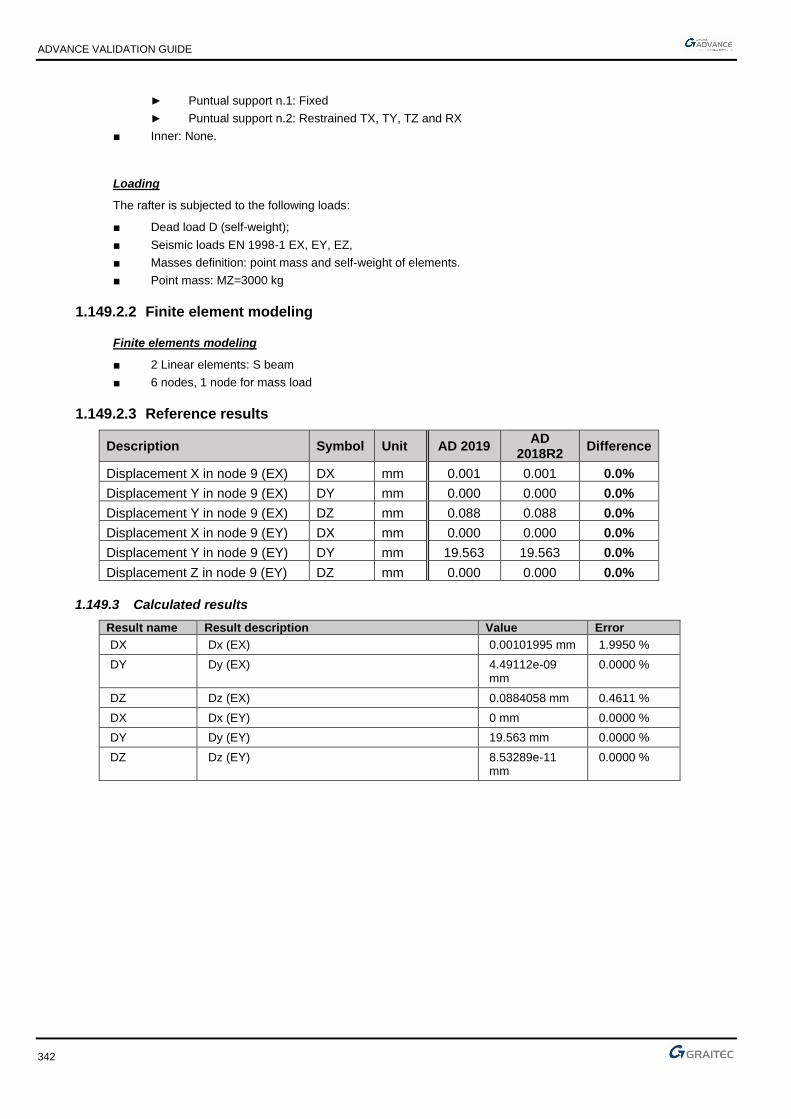
ADVANCE VALIDATION GUIDE
342
► Puntual support n.1: Fixed
► Puntual support n.2: Restrained TX, TY, TZ and RX
■ Inner: None.
Loading
The rafter is subjected to the following loads:
■ Dead load D (self-weight);
■ Seismic loads EN 1998-1 EX, EY, EZ,
■ Masses definition: point mass and self-weight of elements.
■ Point mass: MZ=3000 kg
1.149.2.2 Finite element modeling
Finite elements modeling
■ 2 Linear elements: S beam
■ 6 nodes, 1 node for mass load
1.149.2.3 Reference results
Description Symbol Unit AD 2019 AD
2018R2 Difference
Displacement X in node 9 (EX) DX mm 0.001 0.001 0.0%
Displacement Y in node 9 (EX) DY mm 0.000 0.000 0.0%
Displacement Y in node 9 (EX) DZ mm 0.088 0.088 0.0%
Displacement X in node 9 (EY) DX mm 0.000 0.000 0.0%
Displacement Y in node 9 (EY) DY mm 19.563 19.563 0.0%
Displacement Z in node 9 (EY) DZ mm 0.000 0.000 0.0%
1.149.3 Calculated results
Result name Result description Value Error
DX Dx (EX) 0.00101995 mm 1.9950 %
DY Dy (EX) 4.49112e-09 mm
0.0000 %
DZ Dz (EX) 0.0884058 mm 0.4611 %
DX Dx (EY) 0 mm 0.0000 %
DY Dy (EY) 19.563 mm 0.0000 %
DZ Dz (EY) 8.53289e-11 mm
0.0000 %

ADVANCE VALIDATION GUIDE
343
1.150 Dynamic analysis - Verifying modal mass participation percentages on a model with point mass subject to seismic load
Test ID: 6557
Test status: Passed
1.150.1 Description
The test verifies modal mass participation percentages on a model with point mass subject to seismic action. The model consists of two linear elements, one column and one beam made of HEA200 S275 steel. A point mass of Mz=300kg is positioned at the middle of the beam. The column is fixed at the base and the beam has restrained Tx, Ty, Tz and Rz at theright end. Modal mass participation percentages for the first 6 modes will be analyzed.
1.150.2 Background
Verifies the percentage of modal mass on Y direction on a beam subjected a point mass in the middle for EY load case.
1.150.2.1 Model description
■ Analysis type: modal analysis/ bending rigid structure / 3D
■ Element type: linear
■ Mass: MZ = 300 kg
■ Load cases: Dead load D, Seism EN 1998-1 EX, EY, EZ.
Units
Metric System
Geometry
Below are described the column cross section characteristics:
■ HEA200 (European profile)
■ Section area: A = 5383 mm2
Materials properties
Material 275 is used. The following characteristics are used in relation to this / these material(s):
■ Density: = 7850 kg/m3
Boundary conditions
The boundary conditions are described below:
■ Outer:
► Punctual support n.1: Fixed

ADVANCE VALIDATION GUIDE
344
► Punctual support n.2: Restrained at TX, TY, TZ and RX
■ Inner: None.
Loading
The rafter is subjected to the following loads:
■ Dead load D (self-weight),
■ Punctual mass MZ = 3000 kg,
■ Seismic loads EN 1998-1 EX, EY, EZ,
■ Masses definition: Point masses and self-weight of elements,
■ 6 modes.
1.150.2.2 Modeling
Finite elements modeling
■ 2 Linear elements: S beam,
■ 6 nodes, 1 node for mass load
■ 2 rigid punctual supports.
1.150.2.3 Reference results
Description Symbol Unit AD 2019 AD
2018R2 Difference
Modal mass mode nr. 1 Y (%) 74.780 74.780 0.0%
Modal mass mode nr. 2 Y (%) 0 0 0.0%
Modal mass mode nr. 3 Y (%) 0.802 0.802 0.0%
Modal mass mode nr. 4 Y (%) 16.265 16.265 0.0%
Modal mass mode nr. 5 Y (%) 0 0 0.0%
Modal mass mode nr. 6 Y (%) 0.216 0.216 0.0%

ADVANCE VALIDATION GUIDE
345
1.151 Dynamic analysis – Verifying the envelope of node displacement on linear element under Dynamic Temporal Load
Test ID: 6558
Test status: Passed
1.151.1 Description
The test verifies the envelope of node displacement of nodes situated on linear element no. 9 on Z direction. The beam is subject to dynamic temporal load. The model consists of IPE120 and IPE200 beams made of S275 steel. The main beams are pinned at one end and have Tx, Ty, Tz and Rx restrained at the other end. The secondary beams have Ry restrained at both ends. The secondary beams are subject to dynamic temporal loads at the center of the beam having Fz = -5.00 kN, Fz = -3.00 kN, Fz = -2.00 kN. Envelope of node displacements from the dynamic temporal load case will be analyzed.
1.151.2 Background
Verifies the envelopes of the node displacement on Z direction on linear element nr. 9 (nodes nr. 6, 14, 19, 24, 29, 37)
1.151.2.1 Model description
■ Reference: None
■ Analysis type: Time history analysis / bending rigid structure/ 3D
■ Element type: linear (beams)
■ Load cases: Dead load D, Dynamic temporal load DT
Units
Metric System
Geometry
Main beams section IPE 200:
■ Depth: h = 200 mm
■ Width: b = 100 mm
■ Section area: A = 2848 mm2
Secondary beams section IPE 120
■ Depth: h = 120 mm
■ Width: b = 64 mm
■ Section area: A = 1321 mm2

ADVANCE VALIDATION GUIDE
346
Materials properties
Material S275 is used.
Boundary conditions
The boundary conditions are described below for main beams:
■ Outer:
► Fixed on both the extremities;
► Pinned at extremity 1, Restrained at TX, TY, TZ and RX at extremity 2.
■ Inner: None.
The boundary conditions are described below for secondary beams:
■ Outer:
► Released at Ry on Extremity 1 and Extremity 2;
Loading
The purlin is subjected to the following load combinations and actions:
■ Dead load D
■ Dynamic load DT Fz = -5.00 kN, Fz = -3.00 kN, Fz = -2.00 kN from the center to the edge
1.151.2.2 Modeling
Finite elements modeling
■ Linear element: beams
■ 2 Main beams (11 nodes), 5 secondary beams (6 nodes),
■ 7 linear elements.
1.151.2.3 Reference results
Description Symbol Unit AD 2019 AD
2018R2 Difference
Envelope displacement node 6 DZ mm 16.997 16.997 0.0%
Envelope displacement node 14 DZ mm 20.978 20.978 0.0%
Envelope displacement node 19 DZ mm 23.404 23.404 0.0%
Envelope displacement node 24 DZ mm 23.404 23.404 0.0%
Envelope displacement node 29 DZ mm 20.978 20.978 0.0%
Envelope displacement node 37 DZ mm 16.997 16.997 0.0%

ADVANCE VALIDATION GUIDE
347
1.152 Dynamic analysis – Verifying the displacements of a sloped frame rafter subject to horizontal seismic action
Test ID: 6559
Test status: Passed
1.152.1 Description
The test verifies the displacement of a sloped frame rafter with pinned extremities subject to horizontal seismic action. The sloped beam is subject to uniform distributed gravitational load (10kN/m). The columns have HEA200 section while the beam has IPE200 cross section, made of S275 steel. The columns are fixed at the base. The beam has Ry and Rz released at both ends. Displacements from seismic action will be analyzed.
1.152.2 Background
Verifies the displacements on a sloped portal frame rafter (node n.11) with pinned extremities under horizontal seism action (EX and EY).
1.152.2.1 Model description
■ Reference: None
■ Analysis type: Seismic analysis / bending rigid structure / 3D
■ Element type: linear (beams)
■ Load cases: Dead load D, Live load L, Seism EN 1998-1 EX, EY,EZ
:
Units
Metric System
Geometry
Rafter section IPE 200:
■ Depth: h = 200 mm
■ Width: b = 100 mm
■ Section area: A = 2848 mm2
Column sections HEA 200:
■ Depth: h = 190 mm

ADVANCE VALIDATION GUIDE
348
■ Width: b = 200 mm
Section area: A = 5383 mm2
Materials properties
Material S275 is used.
Boundary conditions
The boundary conditions are described below:
■ Outer:
► Column fixed at base (Z=0)
► First column fixed at top (Z=5), second column fixed at top (Z=6)
► Rafter released on both extremities on Ry and Rz.
■ Inner: None.
Loading
The rafter is subjected to the following load combinations and actions:
■ Dead load 1-D self-weight,
■ Live linear load 2 L = 10 kN/m,
■ Seism EN 1998-1 EX, EY, EZ,
■ Masses definition: obtained by combining static load cases
1.152.2.2 Modeling
Finite elements modeling
■ Linear element: S beam,
■ 6 nodes for first column, 6 nodes for rafter, 7 nodes for the second column
■ 3 linear elements
1.152.2.3 Reference results
Description Symbol Unit AD 2019 AD
2018R2 Difference
Displacement X node n.11 (EX) DX mm 57.729 57.729 0.0%
Displacement Y node n.11 (EX) DY mm 0.000 0.000 0.0%
Displacement Z node n.11 (EX) DZ mm 0.002 0.002 0.0%
Displacement X node n.11 (EY) DX mm 0.000 0.000 0.0%
Displacement Y node n.11 (EY) DY mm 54.079 54.079 0.0%
Displacement Z node n.11 (EY) DZ mm 0.000 0.000 0.0%

ADVANCE VALIDATION GUIDE
349
1.153 Dynamic analysis – Verifying the envelope of node displacement on linear element with elastic releases subject to Dynamic Temporal Load
Test ID: 6560
Test status: Passed
1.153.1 Description
The test verifies the envelope of node displacement of nodes situated on linear elements. The beam is subject to dynamic temporal load. The model consists of IPE120 and IPE200 beams made of S275 steel. The main beams are pinned at one end and have Tx, Ty, Tz and Rx restrained at the other end. The secondary beams have Ry elastic releases at both ends. The secondary beams are subject to dynamic temporal loads at the center of the beam having Fz = -5.00 kN, Fz = -3.00 kN, Fz = -2.00 kN. Envelope of node displacements from the dynamic temporal load case will be analyzed.
1.153.2 Background
Verifies the envelope of the displacement on Z direction of linear element n.5 (on nodes 8, 12, 17, 22, 27, 35) with elastic releases on the ends on Ry.
1.153.2.1 Model description
■ Reference: None
■ Analysis type: Time-history analysis / bending rigid structure/ 3D
■ Element type: Linear (beams)
■ Load cases: Dead load D, Dynamic temporal load DT
Units
Metric System
Geometry
Main beams section HEA 220:
■ Depth: h = 210 mm
■ Width: b = 220 mm
■ Section area: A = 6434 mm2
Secondary beams section IPE 120
■ Depth: h = 120 mm
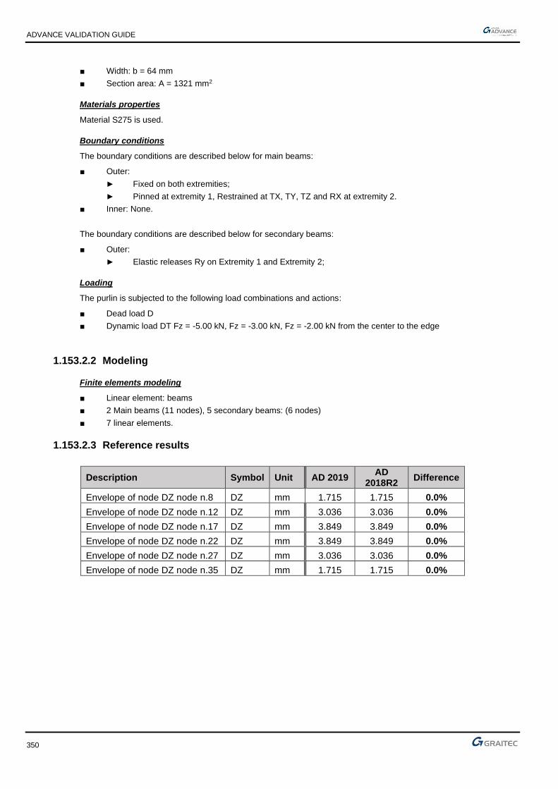
ADVANCE VALIDATION GUIDE
350
■ Width: b = 64 mm
■ Section area: A = 1321 mm2
Materials properties
Material S275 is used.
Boundary conditions
The boundary conditions are described below for main beams:
■ Outer:
► Fixed on both extremities;
► Pinned at extremity 1, Restrained at TX, TY, TZ and RX at extremity 2.
■ Inner: None.
The boundary conditions are described below for secondary beams:
■ Outer:
► Elastic releases Ry on Extremity 1 and Extremity 2;
Loading
The purlin is subjected to the following load combinations and actions:
■ Dead load D
■ Dynamic load DT Fz = -5.00 kN, Fz = -3.00 kN, Fz = -2.00 kN from the center to the edge
1.153.2.2 Modeling
Finite elements modeling
■ Linear element: beams
■ 2 Main beams (11 nodes), 5 secondary beams: (6 nodes)
■ 7 linear elements.
1.153.2.3 Reference results
Description Symbol Unit AD 2019 AD
2018R2 Difference
Envelope of node DZ node n.8 DZ mm 1.715 1.715 0.0%
Envelope of node DZ node n.12 DZ mm 3.036 3.036 0.0%
Envelope of node DZ node n.17 DZ mm 3.849 3.849 0.0%
Envelope of node DZ node n.22 DZ mm 3.849 3.849 0.0%
Envelope of node DZ node n.27 DZ mm 3.036 3.036 0.0%
Envelope of node DZ node n.35 DZ mm 1.715 1.715 0.0%

ADVANCE VALIDATION GUIDE
351
1.154 Dynamic analysis – Verifying the displacements of a sloped frame rafter with elastic releases subject to horizontal seismic action
Test ID: 6562
Test status: Passed
1.154.1 Description
The test verifies the displacement of a sloped frame rafter with elastic releases subject to horizontal seismic action. The sloped beam is subject to uniform distributed gravitational load (10kN/m). The columns have HEA200 section while the beam has IPE200 cross section, made of S275 steel. The columns are fixed at the base. The beam has Ry elastic released at both ends. Displacements from seismic action will be analyzed.
1.154.2 Background
Verifies the displacements on a sloped portal frame rafter (node n.11) with elastic releases at both ends subject to horizontal seism action.
1.154.2.1 Model description
■ Reference: None
■ Analysis type: Seismic analysis / bending rigid structure / 3D
■ Element type: Linear
■ Load cases: Dead load D, Live load L, Seism EN 1998-1 EX, EY,EZ
:
Units
Metric System
Geometry
Rafter section IPE 200:
■ Depth: h = 200 mm
■ Width: b = 100 mm
■ Section area: A = 2848 mm2
Column sections HEA 200:
■ Depth: h = 190 mm

ADVANCE VALIDATION GUIDE
352
■ Width: b = 200 mm
Section area: A = 5383 mm2
Materials properties
Material S275 is used.
Boundary conditions
The boundary conditions are described below:
■ Outer:
► Column fixed at base (Z=0),
► First column fixed at top (Z=5), second column fixed at top (Z=6),
► Rafter with elastic releases at both extremities on Ry.
■ Inner: None.
Loading
The rafter is subjected to the following load combinations and actions:
■ Dead load 1-D self-weight,
■ Live linear load 2-L = 10 kN/m,
■ Seism EN 1998-1 EX, EY, EZ,
■ Masses definition: obtained by combining static load cases.
1.154.2.2 Modeling
Finite elements modeling
■ Linear element: S beam,
■ 6 nodes for first column, 6 nodes for rafter, 7 nodes for the second column
■ 3 linear elements
1.154.2.3 Reference results
Description Symbol Unit AD 2019 AD
2018R2 Difference
Displacement node n.11 for EX DX mm 38.223 38.223 0.0%
Displacement node n.11 for EX DY mm 0.000 0.000 0.0%
Displacement node n.11 for EX DZ mm 0.046 0.046 0.0%
Displacement node n.11 for EY DX mm 0.000 0.000 0.0%
Displacement node n.11 for EY DY mm 54.559 54.559 0.0%
Displacement node n.11 for EY DZ mm 0.000 0.000 0.0%

ADVANCE VALIDATION GUIDE
353
1.155 Time history analysis – Verifying the displacements on a column with fixed support subject to dynamic temporal load at the top
Test ID: 6563
Test status: Passed
1.155.1 Description
The test verifies displacements of a cantilever column subject to dynamic temporal load. The column is fixed at the bottom and is subject to dynamic temporal load of 1.0kN on x direction at the top. Cross section is HEB100 made of S235 steel with a 5m height. Displacements on nodes will be analyzed from the Dynamic temporal load case.
1.155.2 Background
Verifies horizontal displacements on a cantilever column (S beam type). Column is loaded by punctual dynamic temporal load at top 1 kN in X direction.
1.155.2.1 Model description
■ Reference: none,
■ Analysis type: static linear/ 3D,
■ Element type: linear,
■ Load cases: dynamic temporal load FX = 1.00 kN,
Units
Metric System
Geometry
■Section: HEB100 (European Profiles),
■ Height: H=5.00 m,
Materials properties
Material S235
The boundary conditions are described below:
■ Rigid Punctual Support n°1:
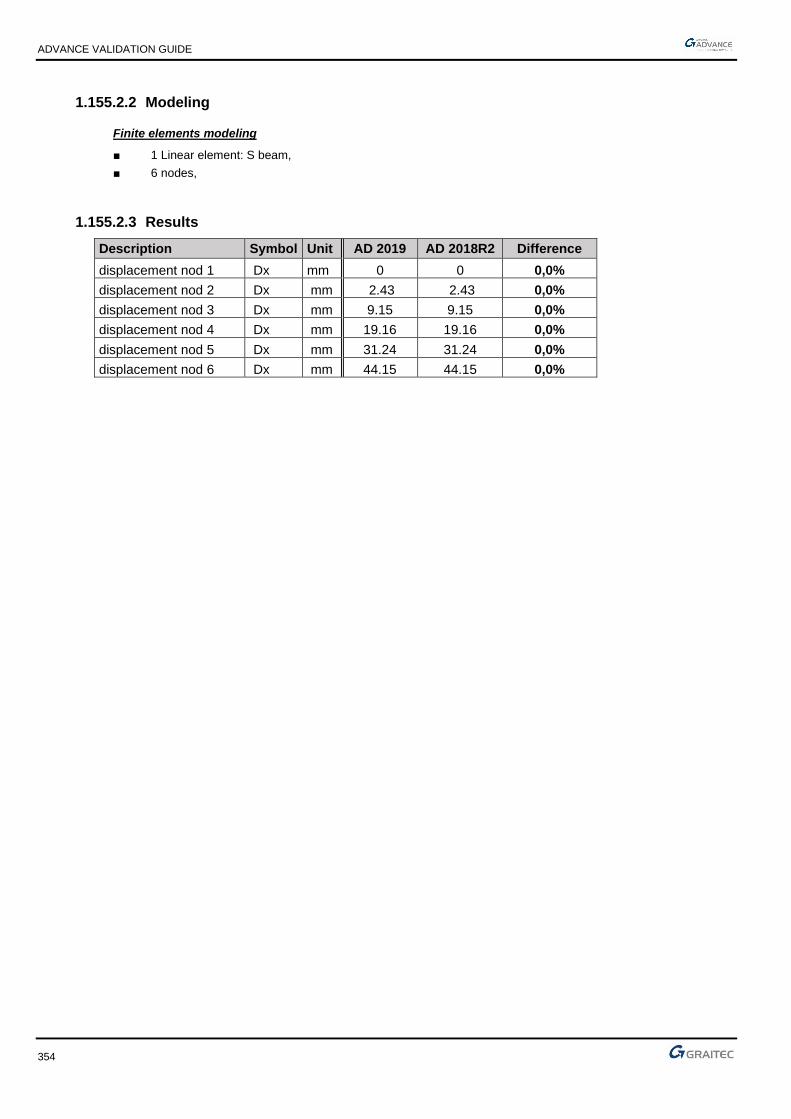
ADVANCE VALIDATION GUIDE
354
1.155.2.2 Modeling
Finite elements modeling
■ 1 Linear element: S beam,
■ 6 nodes,
1.155.2.3 Results
Description Symbol Unit AD 2019 AD 2018R2 Difference
displacement nod 1 Dx mm 0 0 0,0%
displacement nod 2 Dx mm 2.43 2.43 0,0%
displacement nod 3 Dx mm 9.15 9.15 0,0%
displacement nod 4 Dx mm 19.16 19.16 0,0%
displacement nod 5 Dx mm 31.24 31.24 0,0%
displacement nod 6 Dx mm 44.15 44.15 0,0%

ADVANCE VALIDATION GUIDE
355
1.156 Time history analysis – Verifying the displacements on a column with elastic punctual support (global coordinate system) subject to dynamic temporal load at the top
Test ID: 6564
Test status: Passed
1.156.1 Description
The test verifies displacements of a cantilever column subject to dynamic temporal load. The column has elastic point support at the bottom and is subject to dynamic temporal load of 1.0kN on x direction at the top. The elastic point support is defined in global coordinate system Cross section is HEB100 made of S235 steel with a 5m height. Displacements on nodes will be analyzed from the Dynamic temporal load case.
1.156.2 Background
Verifies horizontal displacements on a cantilever column (S beam type) with elastic punctual support. Column is loaded by punctual dynamic temporal load at top 1 kN in X direction.
1.156.2.1 Model description
■ Reference: none,
■ Analysis type: static linear/ 3D,
■ Element type: linear,
■ Load cases: dynamic temporal load FX = 1.00 kN,
Units
Metric System
Geometry
■ Section: HEB100 (European Profiles),
■ Height: 5.00 m.
ADVANCE VALIDATION GUIDE
356
Materials properties
Material S235
The boundary conditions are described below:
■ Elastic Punctual Support n°1 – Stiffness: KTX = 100,0 kN/m,
(global coordinate system) KTY = 100,0 kN/m,
KTZ = 100,0 kN/m,
KRX = 100,0 kN*m/°,
KRY = 100,0 kN*m/°,
KRZ = 100,0 kN*m/°,
1.156.2.2 Modeling
Finite elements modeling
■ 1 Linear element: S beam,
■ 6 nodes,
1.156.2.3 Results
Description Symbol Unit AD 2019 AD 2018R2 Difference
displacement nod 1 Dx mm 9.68 9.68 0,0%
displacement nod 2 Dx mm 13.24 13.24 0,0%
displacement nod 3 Dx mm 21.21 21.21 0,0%
displacement nod 4 Dx mm 32.23 32.23 0,0%
displacement nod 5 Dx mm 44.94 44.94 0,0%
displacement nod 6 Dx mm 58.26 58.26 0,0%

ADVANCE VALIDATION GUIDE
357
1.157 Time history analysis – Verifying the displacements on a column with elastic punctual support (local coordinate system) subject to dynamic temporal load at the top
Test ID: 6565
Test status: Passed
1.157.1 Description
The test verifies displacements of a cantilever column subject to dynamic temporal load. The column has elastic point support at the bottom and is subject to dynamic temporal load of 1.0kN on x direction at the top. The elastic point support is defined in local coordinate system. Cross section is HEB100 made of S235 steel with a 5m height. Displacements on nodes will be analyzed from the Dynamic temporal load case.
1.157.2 Background
Verifies horizontal displacements on a cantilever column (S beam type). Column is loaded by punctual dynamic temporal load at top 1 kN in X. direction. The elastic point support is defined in local coordinate system.
1.157.2.1 Model description
■ Reference: none
■ Analysis type: static linear / 3D
■ Element type: linear
■ Load cases: dynamic temporal load FX = 1,0 kN
Units
Metric System
Geometry
Cross sections:
■ HEB100 (European Profiles)
■ Height 5 m

ADVANCE VALIDATION GUIDE
358
Materials properties
Material S235
The boundary conditions are described below:
■ Elastic Punctual Support n°1 – Stiffness: KTX = 100,0 kN/m
(local coordinate system) KTY = 100,0 kN/m
KTZ = 100,0 kN/m
KRX = 100,0 kN*m/°
KRY = 100,0 kN*m/°
KRZ = 100,0 kN*m/°
1.157.2.2 Modeling
Finite elements modeling
■ 1 Linear element: S beam,
■ 6 nodes,
1.157.2.3 Results
Description Symbol Unit AD 2019 AD 2018R2 Difference
displacement nod 1 Dx mm 9.68 9.68 0,0%
displacement nod 2 Dx mm 13.24 13.24 0,0%
displacement nod 3 Dx mm 21.21 21.21 0,0%
displacement nod 4 Dx mm 32.23 32.23 0,0%
displacement nod 5 Dx mm 44.94 44.94 0,0%
displacement nod 6 Dx mm 58.26 58.26 0,0%

ADVANCE VALIDATION GUIDE
359
1.158 Time history analysis – Verifying the displacements on shell element with linear elastic support (global coordinate system) subject to point dynamic temporal load
Test ID: 6566
Test status: Passed
1.158.1 Description
The test verifies displacements of a cantilever shell element subject to two points dynamic temporal loads. The shell has a linear elastic support at the bottom, defined in global coordinate system. The shell has 5x5m dimensions with 10cm thickness made of S235 steel. The mesh is defined as Delaunay triangles and quadrangles T3-Q4 with 1m mesh size. The two loads are pointed at the top corner on x and y direction F=1kN. The test verifies the node displacements from the dynamic temporal loads case.
1.158.2 Background
Verifies horizontal displacements on a cantilever wall (shell element type). Wall is subject to two punctual dynamic temporal loads at top 1 kN in X and 1 kN in Y directions. The wall has one linear elastic support, defined in global coordinate system.
1.158.2.1 Model description
■ Reference: none
■ Analysis type: static planar / 3D
■ Element type: planar
■ Load cases: dynamic temporal load FX = 1,0 kN, FY = 1,0 kN
Units
Metric System
Geometry
■ Length 5 m
■ Height 5 m
■ Thickness 0,1 m

ADVANCE VALIDATION GUIDE
360
Materials properties
Material S235
The boundary conditions are described below:
■ Elastic Linear Support n°1 – Stiffness: KTX = 100,0 kN/m
(global coordinate system) KTY = 100,0 kN/m
KTZ = 100,0 kN/m
KRX = 100,0 kN*m/°
KRY = 100,0 kN*m/°
KRZ = 100,0 kN*m/°
1.158.2.2 Modeling
Finite elements modeling
■ planar element: shell,
■ 36 nodes,
1.158.2.3 Results
Description Symbol Unit AD 2019 AD 2018R2 Difference
displacement nod 3 (bottom) (D) mm 5.28 5.28 0,0%
displacement nod 36 (top) (D) mm 42.43 42.43 0,0%

ADVANCE VALIDATION GUIDE
361
1.159 Time history analysis – Verifying the displacements on shell element with linear elastic support (local coordinate system) subject to point dynamic temporal load
Test ID: 6567
Test status: Passed
1.159.1 Description
The test verifies displacements of a cantilever shell element subject to two points dynamic temporal loads. The shell has a linear elastic support at the bottom, defined in local coordinate system. The shell has 5x5m dimensions with 10cm thickness made of S235 steel. The mesh is defined as Delaunay triangles and quadrangles T3-Q4 with 1m mesh size. The two loads are pointed at the top corner on x and y direction F=1kN. The test verifies the node displacements from the dynamic temporal loads case.
1.159.2 Background
Verifies horizontal displacements on a cantilever wall (shell element type). Wall is subject to two punctual dynamic temporal loads at top 1 kN in X and 1 kN in Y directions. The wall has one linear elastic support, defined in local coordinate system.
1.159.2.1 Model description
■ Reference: none
■ Analysis type: static planar / 3D
■ Element type: planar
■ Load cases: dynamic temporal load FX = 1,0 kN, FY = 1,0 kN
Units
Metric System
Geometry
■ Length 5 m
■ Height 5 m
■ Thickness 0,1 m

ADVANCE VALIDATION GUIDE
362
Materials properties
Material S235
The boundary conditions are described below:
■ Elastic Linear Support n°1 – Stiffness: KTX = 100,0 kN/m
(local coordinate system) KTY = 100,0 kN/m
KTZ = 100,0 kN/m
KRX = 100,0 kN*m/°
KRY = 100,0 kN*m/°
KRZ = 100,0 kN*m/°
1.159.2.2 Modeling
Finite elements modeling
■ planar element: shell,
■ 36 nodes,
1.159.2.3 Results
Description Symbol Unit AD 2019 AD 2018R2 Difference
displacement nod 3 (bottom) (D) mm 5.28 5.28 0,0%
displacement nod 36 (top) (D) mm 42.43 42.43 0,0%

ADVANCE VALIDATION GUIDE
363
1.160 Time history analysis – Verifying the displacements on a cantilever column connected to a steel plate on elastic support in global coordinate system
Test ID: 6568
Test status: Passed
1.160.1 Description
The test verifies the node displacements of a cantilever column connected to a steel plate.
The plate is resting on a planar elastic support. The column is subjected on X direction to a 1 kN dynamic temporal load applied at the top of the column. The column is a HEB100 made of S235 steel with a 5 m height. The plate has 1x1 m dimensions with a 10 cm thickness made of S235 steel. Dx horizontal displacements from the dynamic temporal load case will be analyzed.
1.160.2 Background
Verifies displacements on a cantilever column (S beam type) connected to steel plate. Column is loaded by punctual dynamic temporal load at top 1 kN in X. Support of plate is Elastic planar.
1.160.2.1 Model description
■ Reference: none
■ Analysis type: static linear and planar / 3D
■ Element type: linear, planar
■ Load cases: dynamic temporal load FX = 1,0 kN
Units
Metric System
Geometry:
■ Column cross section HEB100 (European Profiles)
■ Column Height 5 m
■ Plate Length and Width 1x1 m
■ Plate Thickness 0,1 m

ADVANCE VALIDATION GUIDE
364
Materials properties
Material S235
The boundary conditions are described below:
■ Elastic planar Support n°1 – Stiffness: KTX = 100,0 kN/m
(global coordinate system) KTY = 100,0 kN/m
KTZ = 100,0 kN/m
KRX = 100,0 kN*m/°
KRY = 100,0 kN*m/°
KRZ = 100,0 kN*m/°
1.160.2.2 Modeling
Finite elements modeling
■ planar element: shell,
■ 1 Linear element: S beam,
■ 14 nodes
1.160.2.3 Results
Description Symbol Unit AD 2019 AD 2018R2 Difference
displacement nod 3 (bottom) (Dx) mm 3.27 327 0,0%
displacement nod 14 (top) (Dx) mm 4.11 4.11 0,0%

ADVANCE VALIDATION GUIDE
365
1.161 Time history analysis – Verifying displacements and forces for bar elements subject to dynamic temporal load
Test ID: 6570
Test status: Passed
1.161.1 Description
The test verifies displacements and forces on a plane truss structure made entirely of “bar” type elements subject to dynamic temporal loads. The bar elements have 75x75 mm square cross section made of G40.21M-350W steel. The truss has one fixed support and one with Tx translations released. The dynamic temporal load is pointed at the top left corner of the truss having Fx=10 kN. The dynamic temporal load is defined as a harmonic function with 200 rad/s pulsation for 20 seconds. Displacements (D) and axial force resulted from the dynamic temporal load case will be analyzed.
1.161.2 Background
Check the reaction, behavior and internal forces for a truss structure made entirely of “bar” elements subjected to a dynamic load.
1.161.2.1 Model description
■ Reference: none
■ Analysis type: dynamic / time history / truss structure 2D
■ Element type: linear (bar)
■ Load cases: Dynamic
Units
Metric System
Geometry
Below are described the cross-section characteristics:
■ Depth: h = 75mm
■ Width: b = 75mm

ADVANCE VALIDATION GUIDE
366
Materials properties
Material(s) CSA G40-350W is used.
Boundary conditions
The boundary conditions are described below:
■ Punctual Support 1: Fixed
■ Punctual Support 2:
► Tx: free
► Ty: fixed
► Tz: fixed
► Rx: fixed
► Ry: fixed
► Rz: fixed
Loading
The column is subjected to the following loads:
■ 1 punctual dynamic load of 10kN:
1.161.2.2 Modeling
Finite elements modeling
■ 9 Linear elements: all Bar
■ 6 nodes
■ 2 rigid point supports
■ 1 punctual dynamic load
1.161.2.3 Results
Description Symbol Unit AD 2019 AD 2018R2 Difference
Displacement (MaxD) D mm 1.052882 1.052882 0.0%
Displacement (@10s) D mm 0.401430 0.401430 0.0%
Axial Force (MaxD) Fx kN 226.383823 226.38382 0.0%

ADVANCE VALIDATION GUIDE
367
1.162 Time history analysis – Verifying displacements, forces and bending moments for beam elements structure subject to dynamic temporal loads
Test ID: 6571
Test status: Passed
1.162.1 Description
The test verifies displacements and forces on a plane truss structure made entirely of “beam” type elements subject to dynamic temporal loads. The beam elements have 75x75 mm square cross section made of G40.21M-350W steel. The truss has one pinned support and one with Tx and Ry restraints released. The dynamic temporal load is pointed at the top left corner of the truss having Fx=50 kN. The dynamic temporal load is defined as a harmonic function with 2 rad/s pulsation for 20 seconds. Displacements (D), axial force and bending moments resulted from the dynamic temporal load case will be analyzed.
1.162.2 Background
Check the reaction, behavior and internal forces for a truss structure made entirely of “Beam” elements subjected to a dynamic load.
1.162.2.1 Model description
■ Reference: none
■ Analysis type: dynamic / time history / truss structure 2D
■ Element type: linear (beam)
■ Load cases: Dynamic
Units
Metric System
Geometry
Below are described the cross-section characteristics:
■ Depth: h = 75mm
■ Width: b = 75mm

ADVANCE VALIDATION GUIDE
368
Materials properties
Material(s) CSA G40-350W is used.
Boundary conditions
The boundary conditions are described below:
■ Punctual Support 1: pinned
■ Punctual Support 2:
► Tx: free
► Ty: fixed
► Tz: fixed
► Rx: fixed
► Ry: free
► Rz: fixed
Loading
The column is subjected to the following loads:
■ 1 punctual dynamic load of 50kN:
1.162.2.2 Modeling
Finite elements modeling
■ 9 Linear elements: all beam elements
■ 75 nodes
■ 2 rigid point supports
■ 1 punctual dynamic load
1.162.2.3 Results
Description Symbol Unit AD 2019 AD 2018R2 Difference
Displacement (MaxD) D mm 0.664 0.664 0.0%
Displacement (@10s) D mm 0.513 0.513 0.0%
Axial Force (MaxD) Fx kN 54.72 54.72 0.0%
Bending Moment (MaxD) My kN.m 0.20 0.20 0.0%

ADVANCE VALIDATION GUIDE
369
1.163 Time history analysis - Verifying displacements, forces and bending moments for S beam elements structure subject to dynamic temporal loads
Test ID: 6572
Test status: Passed
1.163.1 Description
The test verifies displacements and forces on a plane truss structure made entirely of “S beam” type elements subject to dynamic temporal loads. The S beam elements have 75x75 mm square cross section made of G40.21M-350W steel. The truss has one pinned support and one with Tx and Ry restraints released. The dynamic temporal load is pointed at the top left corner of the truss having Fx=50 kN. The dynamic temporal load is defined as a harmonic function with 2 rad/s pulsation for 20 seconds. Displacements (D), axial force and bending moments resulted from the dynamic temporal load case will be analyzed.
1.163.2 Background
Check the reaction, behavior and internal forces for a truss structure made entirely of “S Beam” elements subjected to a dynamic load.
1.163.2.1 Model description
■ Reference: none
■ Analysis type: dynamic / time history / truss structure 2D
■ Element type: linear (S beam)
■ Load cases: Dynamic
Units
Metric System
Geometry
Below are described the cross-section characteristics:
■ Depth: h = 75mm
■ Width: b = 75mm

ADVANCE VALIDATION GUIDE
370
Materials properties
Material(s) CSA G40-350W is used.
Boundary conditions
The boundary conditions are described below:
■ Punctual Support 1: pinned
■ Punctual Support 2:
► Tx: free
► Ty: fixed
► Tz: fixed
► Rx: fixed
► Ry: free
► Rz: fixed
Loading
The column is subjected to the following loads:
■ 1 punctual dynamic load of 50kN:
1.163.2.2 Modeling
Finite elements modeling
■ 9 Linear elements: all Sbeam elements
■ 75 nodes
■ 2 rigid point supports
■ 1 punctual dynamic load
1.163.2.3 Results
Description Symbol Unit AD 2019 AD 2018R2 Difference
Displacement (MaxD) D mm 0.6187 0.6187 0.0%
Displacement (@10s) D mm 0.0396 0.0396 0.0%
Axial Force (MaxD) Fx kN 50.79 50.79 0.0%
Bending Moment (MaxD) My kN.m 0.009 0.009 0.0%

ADVANCE VALIDATION GUIDE
371
1.164 Time history analysis - Verifying displacements, forces and bending moments for variable beam elements structure subject to dynamic temporal loads
Test ID: 6573
Test status: Passed
1.164.1 Description
The test verifies displacements and forces on a plane truss structure made entirely of “variable beam” type elements subject to dynamic temporal loads. The variable beam elements have 25x52 mm to 25x200mm variable cross section made of G40.21M-350W steel. The truss has one pinned support and one with Tx and Ry restraints released. The dynamic temporal load is pointed at the top left corner of the truss having Fx=50 kN. The dynamic temporal load is defined as a harmonic function with 2 rad/s pulsation for 20 seconds. Displacements (D), axial force and bending moments resulted from the dynamic temporal load case will be analyzed.
1.164.2 Background
Check the reaction, behavior and internal forces for a truss structure made entirely of “Variable Beam” elements subjected to a dynamic load.
1.164.2.1 Model description
■ Reference: none
■ Analysis type: dynamic / time history / truss structure 2D
■ Element type: linear (variable beam)
■ Load cases: Dynamic
Units
Metric System
Geometry
Below are described the cross-section characteristics:
■ Start Cross-Section
▪ Depth: h = 50mm
▪ Width: b = 25mm
■ End Cross-section
▪ Depth: h = 200mm
▪ Width: b = 25mm

ADVANCE VALIDATION GUIDE
372
Materials properties
Material(s) CSA G40-350W is used.
Boundary conditions
The boundary conditions are described below:
■ Punctual Support 1: pinned
■ Punctual Support 2:
► Tx: free
► Ty: fixed
► Tz: fixed
► Rx: fixed
► Ry: free
► Rz: fixed
Loading
The column is subjected to the following loads:
■ 1 punctual dynamic load of 50kN:
1.164.2.2 Modeling
Finite elements modeling
■ 9 Linear elements: all variable beam elements
■ 75 nodes
■ 2 rigid point supports
■ 1 punctual dynamic load
1.164.2.3 Results
Description Symbol Unit AD 2019 AD 2018R2 Difference
Displacement (MaxD) D mm 1.3216 1.3216 0.0%
Displacement (@10s) D mm 1.0644 1.0644 0.0%
Axial Force (MaxD) Fx kN 52.30 52.30 0.0%
Bending Moment (MaxD) My kN.m 0.43 0.43 0.0%

ADVANCE VALIDATION GUIDE
373
1.165 Time history analysis – Verifying displacements and bending moments for a plate type element subject to dynamic temporal load case
Test ID: 6574
Test status: Passed
1.165.1 Description
The test verifies the displacements and bending moments on a plate type element resulted from a dynamic temporal load. The plate has 2x6 m in plane dimensions with 15 cm thickness made of C25/30 concrete. The plate is supported on four point supports. The plate is subject to 5kN/m2 gravitational uniform distributed load defined as dynamic temporal load. The mesh is defined as Delaunay triangles and quadrangles T3-Q4 with 0.1 m mesh size. Displacements and bending moments resulted from the dynamic temporal load case will be verified.
1.165.2 Background
Check the reaction, behavior and internal forces for a structure made entirely of “plate” surface elements subjected to a dynamic load.
1.165.2.1 Model description
■ Reference: none
■ Analysis type: dynamic / time history / bending rigid structure 3D
■ Element type: Planar (plate)
■ Load cases: Dynamic
Units
Metric System
Geometry
Below are described the cross-section characteristics:
■ Thickness: 150mm
Materials properties
Material(s) concrete C25/30 is used.

ADVANCE VALIDATION GUIDE
374
Boundary conditions
The boundary conditions are described below:
■ Point Support 1:
▪ Tx: fixed
▪ Ty: fixed
▪ Tz: fixed
▪ Rz: fixed
■ Point Support 2:
▪ Tz: fixed
■ Point Support 3:
▪ Tz: fixed
■ Point Support 4:
▪ Tz: fixed
The floor is subjected to the following loads:
■ 1 planar dynamic load of -5kN/m^2:
1.165.2.2 Modeling
Finite elements modeling
■ 1 planar element: plate
■ 1281 nodes (mesh 100mm)
■ 4 point supports
■ 1 planar dynamic load
1.165.2.3 Results
Description Symbol Unit AD 2019 AD 2018R2 Difference
Displacement (MaxD) D mm 15.793817 15.793817 0.0%
Displacement (@10s) D mm 4.467070 4.467070 0.0%
Moment (MaxD) Mxx kN.m 8.99 8.99 0.0%
Moment (MaxD) Myy kN.m 37.30 37.30 0.0%

ADVANCE VALIDATION GUIDE
375
1.166 Time history analysis – Verifying displacements for a rigid membrane model subject to time history analysis load case
Test ID: 6575
Test status: Passed
1.166.1 Description
The test verifies the displacements on a model made of rigid membrane elements resulted from a dynamic temporal load case. The structure is subject to 400kN/m linear load applied at the top. The load is defined as dynamic temporal with a harmonic function. The rigid membranes have 10 cm thickness made of C25/30 concrete. The structure is supported on four pinned linear supports. The mesh is defined as Delaunay triangles and quadrangles T3-Q4 with 0.1 m mesh size. Displacements resulted from the dynamic temporal load case will be verified.
1.166.2 Background
Check the reaction, behavior and internal forces for a structure made entirely of “rigid membrane” surface elements subjected to a dynamic load.
1.166.2.1 Model description
■ Reference: none
■ Analysis type: dynamic / time history / bending rigid structure 3D
■ Element type: Planar (rigid mebrane)
■ Load cases: Dynamic
Units
Metric System
Geometry
Below are described the cross-section characteristics:
■ Thickness: 100mm

ADVANCE VALIDATION GUIDE
376
Materials properties
Material(s) concrete C25/30 is used.
Boundary conditions
The boundary conditions are described below:
■ Linear Support 1: Pinned
■ Linear Support 2: Pinned
■ Linear Support 3: Pinned
■ Linear Support 4: Pinned
The core wall system is subjected to the following loads:
■ 1 linear dynamic load of 400kN/m:
1.166.2.2 Modeling
Finite elements modeling
■ 5 planar elements: rigid membrane
■ 36 nodes
■ 4 rigid linear supports
■ 1 linear dynamic load
1.166.2.3 Results
Description Symbol Unit AD 2019 AD 2018R2 Difference
Displacement (MaxD) D mm 1.796238 1.796238 0.0%
Displacement (@10s) D mm 0.803732 0.803732 0.0%

ADVANCE VALIDATION GUIDE
377
1.167 NL static analysis on T/C point supports – Verifying displacements on linear elements and forces on supports operating in compression with elastic stiffness defined in local coordinate system
Test ID: 6576
Test status: Passed
1.167.1 Description
The test verifies a two-span frame response from non-linear static analysis. The structure is subject to 50kN/m gravitational uniform distributed load on one span. S beam elements have IPE500 cross section made of S235 steel. The frame is supported by a fix point in the middle and two T/C point supports with KTx=1000kN/m stiffness. The T/C point supports are operating in compression. The T/C point supports are defined in global coordinate system. Displacements in linear elements and forces in point supports are verified from the non-linear static case.
1.168 NL static analysis on T/C point supports – Verifying displacements on linear elements and forces on supports operating in compression with elastic stiffness defined in global coordinate system
Test ID: 6577
Test status: Passed
1.168.1 Description
The test verifies a two-span frame response from non-linear static analysis. The structure is subject to 50kN/m gravitational uniform distributed load on one span. S beam elements have IPE500 cross section made of S235 steel. The frame is supported by a fix point in the middle and two T/C point supports with KTx=1000kN/m stiffness. The T/C point supports are operating in compression. The T/C point supports are defined in global coordinate system. Displacements in linear elements and forces in point supports are verified from the non-linear static case.
1.169 NL static analysis on T/C point supports – Verifying displacements on linear elements and forces on supports operating in tension with elastic stiffness defined in global coordinate system
Test ID: 6578
Test status: Passed
1.169.1 Description
The test verifies a two-span frame response from non-linear static analysis. The structure is subject to 50kN/m gravitational uniform distributed load on one span. S beam elements have IPE500 cross section made of S235 steel. The frame is supported by a fix point in the middle and two T/C point supports with KTz=1000kN/m stiffness. The T/C point supports are operating in tension. The T/C point supports are defined in global coordinate system. Displacements in linear elements and forces in point supports are verified from the non-linear static case.
1.170 NL static analysis on T/C point supports – Verifying displacements on linear elements and forces on supports operating in tension with elastic stiffness defined in local coordinate system
Test ID: 6580
Test status: Passed
1.170.1 Description
The test verifies a two-span frame response from non-linear static analysis. The structure is subject to 50kN/m gravitational uniform distributed load on one span. S beam elements have IPE500 cross section made of S235 steel. The frame is supported by a fix point in the middle and two T/C point supports with KTx=1000kN/m stiffness. The T/C point supports are operating in tension. The T/C point supports are defined in local coordinate system. Displacements in linear elements and forces in point supports are verified from the non-linear static case.

ADVANCE VALIDATION GUIDE
378
1.171 NL static analysis on T/C linear supports – Verifying displacements on planar elements and torsors on linear supports operating in compression with elastic stiffness defined in global coordinate system
Test ID: 6581
Test status: Passed
1.171.1 Description
The test verifies a two-span frame response from non-linear static analysis. The structure is subject to 100kN/m gravitational uniform distributed load on one span and 100kN point force on “x” direction. The model consists in a shell element with 20cm thickness and a short beam Element with 60x60 cm section made of C25/30 concrete. The frame is supported by a fix point in the middle and two T/C linear supports with KTz=1000kN/m stiffness. The T/C linear supports are operating in compression. The T/C linear supports are defined in local coordinate system. 0.5m mesh size. Displacements in planar elements and torsors in linear supports are verified from the non-linear static case.
1.172 NL static analysis on T/C linear supports – Verifying displacements on planar elements and torsors on linear supports operating in compression with elastic stiffness defined in local coordinate system
Test ID: 6582
Test status: Passed
1.172.1 Description
The test verifies a two-span frame response from non-linear static analysis. The structure is subject to 100kN/m gravitational uniform distributed load on one span and 100kN point force on “x” direction. The model consists in a shell element with 20cm thickness and a short beam Element with 60x60 cm section made of C25/30 concrete. The frame is supported by a fix point in the middle and two T/C linear supports with KTx=1000kN/m stiffness. The T/C linear supports are operating in compression. The T/C linear supports are defined in local coordinate system. 0.5m mesh size. Displacements in planar elements are verified from the non-linear static case.
1.173 NL static analysis on T/C linear supports – Verifying displacements on planar elements and torsors on linear supports operating in tension with elastic stiffness defined in global coordinate system
Test ID: 6583
Test status: Passed
1.173.1 Description
The test verifies a two-span frame response from non-linear static analysis. The structure is subject to 100kN/m gravitational uniform distributed load on one span and 100kN point force on “x” direction. The model consists in a shell element with 20cm thickness and a short beam Element with 60x60 cm section made of C25/30 concrete. The frame is supported by a fix point in the middle and two T/C linear supports with KTz=1000kN/m stiffness. The T/C linear supports are operating in tension. The T/C linear supports are defined in global coordinate system. 0.5m mesh size. Displacements in planar elements and torsors in linear supports are verified from the non-linear static case.

ADVANCE VALIDATION GUIDE
379
1.174 NL static analysis on T/C linear supports – Verifying displacements on planar elements and torsors on linear supports operating in tension with elastic stiffness defined in local coordinate system
Test ID: 6584
Test status: Passed
1.174.1 Description
The test verifies a two-span frame response from non-linear static analysis. The structure is subject to 100kN/m gravitational uniform distributed load on one span and 100kN point force on “x” direction. The model consists in a shell element with 20cm thickness and a short beam Element with 60x60 cm section made of C25/30 concrete. The frame is supported by a fix point in the middle and two T/C linear supports with KTz=1000kN/m stiffness. The T/C linear supports are operating in tension. The T/C linear supports are defined in local coordinate system. 0.5m mesh size. Displacements in planar elements and torsors in linear supports are verified from the non-linear static case.
1.175 NL static analysis on T/C planar supports – Verifying displacements on elements and torsors on supports operating in compression with elastic stiffness defined in global coordinate system
Test ID: 6585
Test status: Passed
1.175.1 Description
The test verifies a two-span frame response from non-linear static analysis. The structure is subject to 125kN/m gravitational uniform distributed load on one span and 200kN point force on “x” direction. The model consists in a shell element with 20cm thickness and two short beam element with 60x60 cm (40x60 cm) section made of C25/30 concrete. The frame is supported by a fix point in the middle and two square shell elements which have T/C planar supports with KTz=1000kN/m stiffness. The T/C planar supports are operating in compression. The T/C planar supports are defined in global coordinate system. 0.5m mesh size. Displacements in planar elements and torsors in planar supports are verified from the non-linear static case.
1.176 NL static analysis on T/C planar supports – Verifying displacements on elements and torsors on supports operating in compression with elastic stiffness defined in local coordinate system
Test ID: 6586
Test status: Passed
1.176.1 Description
The test verifies a two-span frame response from non-linear static analysis. The structure is subject to 125kN/m gravitational uniform distributed load on one span and 200kN point force on “x” direction. The model consists in a shell element with 20cm thickness and two short beam element with 60x60 cm (40x60 cm) section made of C25/30 concrete. The frame is supported by a fix point in the middle and two square shell elements which have T/C planar supports with KTz=1000kN/m stiffness. The T/C planar supports are operating in compression. The T/C planar supports are defined in local coordinate system. 0.5m mesh size. Displacements in planar elements and torsors in planar supports are verified from the non-linear static case.

ADVANCE VALIDATION GUIDE
380
1.177 NL static analysis on T/C planar supports – Verifying displacements on elements and torsors on supports operating in tension with elastic stiffness defined in global coordinate system
Test ID: 6587
Test status: Passed
1.177.1 Description
The test verifies a two-span frame response from non-linear static analysis. The structure is subject to 125kN/m gravitational uniform distributed load on one span and 200kN point force on “x” direction. The model consists in a shell element with 20cm thickness and two short beam element with 60x60 cm (40x60 cm) section made of C25/30 concrete. The frame is supported by a fix point in the middle and two square shell elements which have T/C planar supports with KTz=1000kN/m stiffness. The T/C planar supports are operating in tension. The T/C planar supports are defined in global coordinate system. 0.5m mesh size. Displacements in planar elements and torsors in planar supports are verified from the non-linear static case.
1.178 NL static analysis on T/C planar supports – Verifying displacements on elements and torsors on supports operating in tension with elastic stiffness defined in local coordinate system
Test ID: 6588
Test status: Passed
1.178.1 Description
The test verifies a two-span frame response from non-linear static analysis. The structure is subject to 125kN/m gravitational uniform distributed load on one span and 200kN point force on “x” direction. The model consists in a shell element with 20cm thickness and two short beam element with 60x60 cm (40x60 cm) section made of C25/30 concrete. The frame is supported by a fix point in the middle and two square shell elements which have T/C planar supports with KTz=1000kN/m stiffness. The T/C planar supports are operating in tension. The T/C planar supports are defined in local coordinate system. 0.5m mesh size. Displacements in planar elements and torsors in planar supports are verified from the non-linear static case.

ADVANCE VALIDATION GUIDE
381
1.179 Elastic punctual (local coordinate system) supports in Linear static analysis – Verifying displacements on a cantilever column (S beam type)
Test ID: 6605
Test status: Passed
1.179.1 Description
This test verifies the displacements on a cantilever column subject to horizontal point force and supported on an elastic point support. The column is a HEB100 european profile made of S235 steel with a 5 m height, The elastic point support is defined to have KTx=KTy=KTz=100kN/m and KRx=KRy=KRz=100kNm/° stiffness. The elastic point support is defined in local coordinate system. Nodes displacements are verified after performing static linear analysis on the model.
1.179.2 Background
Verifies horizontal displacements on a cantilever column (S beam type). Column is loaded by point load 1 kN.
1.179.2.1 Model description
■ Reference: none
■ Analysis type: Elastic punctual (local coordinate system) supports in Linear Static analysis
■ Element type: linear
■ Load cases: point load Fx = 1,0 kN
Units
Metric System
Geometry
Cross sections:
■ HEB100 (European Profiles)
■ Height 5 m

ADVANCE VALIDATION GUIDE
382
Materials properties
Material S235
The boundary conditions are described below:
■ Elastic Point Support in local coordinate system
■ Stiffness: (KTX, KTY, KTZ) = 100 kN/m, (KRX, KRY, KRY) =100 kNm/°
1.179.2.2 Modeling
Finite elements modeling
■ 1 Linear element: S beam
■ 6 nodes
1.179.2.3 Results
Description Symbol Unit AD 2019 AD 2018R2 Difference
displacement nod 1 DX mm 10.00 10.00 0.0%
displacement nod 2 DX mm 13.36 13.36 0.0%
displacement nod 3 DX mm 20.95 20.95 0.0%
displacement nod 4 DX mm 31.73 31.73 0.0%
displacement nod 5 DX mm 44.62 44.62 0.0%
displacement nod 6 DX mm 58.57 58.57 0.0%
displacement nod 1 DZ mm -10.02 -10.02 0.0%
displacement nod 2 DZ mm -10.02 -10.02 0.0%
displacement nod 3 DZ mm -10.03 -10.03 0.0%
displacement nod 4 DZ mm -10.03 -10.03 0.0%
displacement nod 5 DZ mm -10.03 -10.03 0.0%
displacement nod 6 DZ mm -10.03 -10.03 0.0%

ADVANCE VALIDATION GUIDE
383
1.180 Elastic linear (global coordinate system) support in Linear static analysis – Verifying displacements on a S type beam subject to point force at midspan
Test ID: 6606
Test status: Passed
1.180.1 Description
This test verifies the displacements on a horizontal S type beam subject to gravitational point force and supported on an elastic linear support. The S beam is a HEB100 european profile made of S235 steel with a 5 m length. The elastic linear support is defined to have KTx=KTy=KTz=100kN/m and KRx=KRy=KRz=100kNm/° stiffness. The elastic linear support is defined in global coordinate system. Nodes displacements are verified after performing static linear analysis on the model.
1.180.2 Background
Verifies vertical displacements on a beam (S beam type). Beam is loaded by point load 1 kN in the middle of the span.
1.180.2.1 Model description
■ Reference: none
■ Analysis type: Elastic linear (global coordinate system) supports in Linear Static analysis
■ Element type: linear
■ Load cases: point load Fx = 1,0 kN
Units
Metric System
Geometry
Cross sections:
■ HEB100 (European Profiles)
■ Length 5 m
Materials properties
Material S235
The boundary conditions are described below:
■ Elastic linear (global coordinate system) supports in Linear Static analysis
■ Stiffness: (KTX, KTY, KTZ) = 100 kN/m, (KRX, KRY, KRY) =100 kNm/°

ADVANCE VALIDATION GUIDE
384
1.180.2.2 Modeling
Finite elements modeling
■ 1 Linear element: S beam
■ 6 nodes
1.180.2.3 Results
Description Symbol Unit AD 2019 AD 2018R2 Difference
displacement nod 1 DZ mm -3.95 -3.95 0.0%
displacement nod 2 DZ mm -3.99 -3.99 0.0%
displacement nod 3 DZ mm -4.05 -4.05 0.0%
displacement nod 4 DZ mm -4.05 -4.05 0.0%
displacement nod 5 DZ mm -3.99 -3.99 0.0%
displacement nod 6 DZ mm -3.95 -3.95 0.0%

ADVANCE VALIDATION GUIDE
385
1.181 Elastic linear (local coordinate system) support in Linear static analysis – Verifying displacements on a S type beam subject to point force at midspan
Test ID: 6607
Test status: Passed
1.181.1 Description
This test verifies the displacements on a horizontal S type beam subject to gravitational point force and supported on an elastic linear support. The S beam is a HEB100 european profile made of S235 steel with a 5 m length. The elastic linear support is defined to have KTx=KTy=KTz=100kN/m and KRx=KRy=KRz=100kNm/° stiffness. The elastic linear support is defined in local coordinate system. Nodes displacements are verified after performing static linear analysis on the model.
1.181.2 Background
Verifies vertical displacements on a beam (S beam type). Beam is loaded by point load 1 kN in the middle of the span.
1.181.2.1 Model description
■ Reference: none
■ Analysis type: Elastic linear (local coordinate system) supports in Linear Static analysis
■ Element type: linear
■ Load cases: point load Fx = 1,0 kN
Units
Metric System
Geometry
Cross sections:
■ HEB100 (European Profiles)
■ Lenght 5 m
Materials properties
Material S235
The boundary conditions are described below:
■ Elastic linear (local coordinate system) supports in Linear Static analysis
■ Stiffness: (KTX, KTY, KTZ) = 100 kN/m, (KRX, KRY, KRY) =100 kNm/°

ADVANCE VALIDATION GUIDE
386
1.181.2.2 Modeling
Finite elements modeling
■ 1 Linear element: S beam
■ 6 nodes
1.181.2.3 Results
Description Symbol Unit AD 2019 AD 2018R2 Difference
displacement nod 1 DZ mm -3.95 -3.95 0.0%
displacement nod 2 DZ mm -3.99 -3.99 0.0%
displacement nod 3 DZ mm -4.05 -4.05 0.0%
displacement nod 4 DZ mm -4.05 -4.05 0.0%
displacement nod 5 DZ mm -3.99 -3.99 0.0%
displacement nod 6 DZ mm -3.95 -3.95 0.0%

ADVANCE VALIDATION GUIDE
387
1.182 Elastic planar support (global coordinate system) in Linear static analysis – Verifying displacements on a horizontal plate (shell type) subject to uniform distributed planar load
Test ID: 6608
Test status: Passed
1.182.1 Description
This test verifies the displacements on a horizontal shell plate subject to gravitational Planar uniform distributed load supported on an elastic planar support. The shell has 20cm thickness and is made of C25/30 concrete. The elastic planar support is defined to have KTx=KTy=KTz=100kN/m and KRx=KRy=KRz=100kNm/° stiffness. The elastic planar support is defined in global coordinate system. Nodes displacements are verified after performing static linear analysis on the model.
1.182.2 Background
Verifies vertical displacements on a plate (shell type). Plate is loaded by area load Fz= -1.00 kN/m2.
1.182.2.1 Model description
■ Reference: none,
■ Analysis type: Elastic planar (global coordinate system) supports in Linear Static analysis,
■ Element type: plate,
■ Load cases: area load Fz = -1.00 kN/m2,
Units
Metric System
Geometry
Cross sections:
■ plate thickness: h= 20 cm,
■ Length*width: L*b=500m x 500 cm.
Materials properties
Material C25/30
The boundary conditions are described below:
■ Elastic planar (global coordinate system) supports in Linear Static analysis
■ Stiffness: (KTX, KTY, KTZ) = 100 kN/m, (KRX, KRY, KRY) =100 kNm/°

ADVANCE VALIDATION GUIDE
388
1.182.2.2 Modeling
Finite elements modeling
■ 1 planar element: plate
■ 9 nodes
1.182.2.3 Results
Description Symbol Unit AD 2019 AD 2018R2 Difference
displacement nod 1 DZ mm -59.03 -59.03 0.0%
displacement nod 2 DZ mm -59.03 -59.03 0.0%
displacement nod 3 DZ mm -59.03 -59.03 0.0%
displacement nod 4 DZ mm -59.03 -59.03 0.0%
displacement nod 5 DZ mm -59.03 -59.03 0.0%
displacement nod 6 DZ mm -59.03 -59.03 0.0%
displacement nod 7 DZ mm -59.03 -59.03 0.0%
displacement nod 8 DZ mm -59.03 -59.03 0.0%
displacement nod 9 DZ mm -59.03 -59.03 0.0%

ADVANCE VALIDATION GUIDE
389
1.183 T/C punctual (local coordinate system) supports in Non-Linear static analysis – Verifying displacements on a cantilever column (S beam type)
Test ID: 6609
Test status: Passed
1.183.1 Description
This test verifies the displacements on a cantilever column subject to horizontal point force and supported on an T/C point support defined to operate in compression. The column is a HEB100 european profile made of S235 steel with a 5 m height. The T/C point support is defined to have KTx=KTy=KTz=100kN/m and KRx=KRy=KRz=100kNm/° stiffness. The T/C point support is defined in local coordinate system. Nodes displacements are verified after performing static non-linear analysis on the model.
1.183.2 Background
Verifies horizontal displacements on a cantilever column (S beam type). Column is loaded by point load 1 kN.
1.183.2.1 Model description
■ Reference: none
■ Analysis type: Elastic punctual (local coordinate system) supports in NL Static analysis
■ Element type: linear
■ Load cases: point load Fx = 1,0 kN
Units
Metric System
Geometry
Cross sections:
■ HEB100 (European Profiles)
■ Height 5 m
Materials properties
Material S235

ADVANCE VALIDATION GUIDE
390
The boundary conditions are described below:
■ Elastic T/C point Support in local coordinate system
■ Stiffness: (KTX, KTY, KTZ) = 100 kN/m, (KRX, KRY, KRY) =100 kNm/°
1.183.2.2 Modeling
Finite elements modeling
■ 1 Linear element: S beam
■ 6 nodes
1.183.2.3 Results
Description Symbol Unit AD 2019 AD 2018R2 Difference
displacement nod 1 DX mm 10.00 10.00 0.0%
displacement nod 2 DX mm 13.36 13.36 0.0%
displacement nod 3 DX mm 20.95 20.95 0.0%
displacement nod 4 DX mm 31.73 31.73 0.0%
displacement nod 5 DX mm 44.62 44.62 0.0%
displacement nod 6 DX mm 58.57 58.57 0.0%
displacement nod 1 DZ mm -10.02 -10.02 0.0%
displacement nod 2 DZ mm -10.02 -10.02 0.0%
displacement nod 3 DZ mm -10.03 -10.03 0.0%
displacement nod 4 DZ mm -10.03 -10.03 0.0%
displacement nod 5 DZ mm -10.03 -10.03 0.0%
displacement nod 6 DZ mm -10.03 -10.03 0.0%

ADVANCE VALIDATION GUIDE
391
1.184 T/C linear (global coordinate system) support in Non-Linear static analysis – Verifying displacements on a S type beam subject to point force at midspan
Test ID: 6610
Test status: Passed
1.184.1 Description
This test verifies the displacements on a horizontal S type beam subject to gravitational point force and supported on an T/C linear support. The S beam is a HEB100 european profile made of S235 steel with a 5 m length. The T/C linear support is defined to have KTx=KTy=KTz=100kN/m and KRx=KRy=KRz=100kNm/° stiffness. The T/C linear support is defined in global coordinate system and imposed to operate in compression. Nodes displacements are verified after performing static non-linear analysis on the model.
1.184.2 Background
Verifies vertical displacements on a beam (S beam type). Beam is loaded by point load 1 kN in the middle of the span.
1.184.2.1 Model description
■ Reference: none
■ Analysis type: Elastic linear (global coordinate system) supports in NL Static analysis
■ Element type: linear
■ Load cases: point load Fx = 1,0 kN
Units
Metric System
Geometry
Cross sections:
■ HEB100 (European Profiles)
■ Lenght 5 m
Materials properties
Material S235
The boundary conditions are described below:
■ Elastic T/C linear (global coordinate system) supports in NL Static analysis
■ Stiffness: (KTX, KTY, KTZ) = 100 kN/m, (KRX, KRY, KRY) =100 kNm/°

ADVANCE VALIDATION GUIDE
392
1.184.2.2 Modeling
Finite elements modeling
■ 1 Linear element: S beam
■ 6 nodes
1.184.2.3 Results
Description Symbol Unit AD 2019 AD 2018R2 Difference
displacement nod 1 DZ mm -3.95 -3.95 0.0%
displacement nod 2 DZ mm -3.99 -3.99 0.0%
displacement nod 3 DZ mm -4.05 -4.05 0.0%
displacement nod 4 DZ mm -4.05 -4.05 0.0%
displacement nod 5 DZ mm -3.99 -3.99 0.0%
displacement nod 6 DZ mm -3.95 -3.95 0.0%
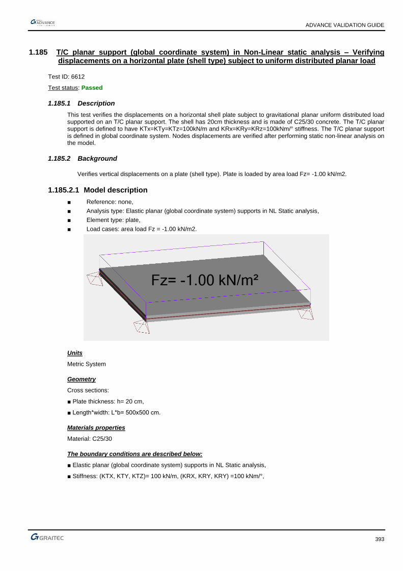
ADVANCE VALIDATION GUIDE
393
1.185 T/C planar support (global coordinate system) in Non-Linear static analysis – Verifying displacements on a horizontal plate (shell type) subject to uniform distributed planar load
Test ID: 6612
Test status: Passed
1.185.1 Description
This test verifies the displacements on a horizontal shell plate subject to gravitational planar uniform distributed load supported on an T/C planar support. The shell has 20cm thickness and is made of C25/30 concrete. The T/C planar support is defined to have KTx=KTy=KTz=100kN/m and KRx=KRy=KRz=100kNm/° stiffness. The T/C planar support is defined in global coordinate system. Nodes displacements are verified after performing static non-linear analysis on the model.
1.185.2 Background
Verifies vertical displacements on a plate (shell type). Plate is loaded by area load Fz= -1.00 kN/m2.
1.185.2.1 Model description
■ Reference: none,
■ Analysis type: Elastic planar (global coordinate system) supports in NL Static analysis,
■ Element type: plate,
■ Load cases: area load Fz = -1.00 kN/m2.
Units
Metric System
Geometry
Cross sections:
■ Plate thickness: h= 20 cm,
■ Length*width: L*b= 500x500 cm.
Materials properties
Material: C25/30
The boundary conditions are described below:
■ Elastic planar (global coordinate system) supports in NL Static analysis,
■ Stiffness: (KTX, KTY, KTZ)= 100 kN/m, (KRX, KRY, KRY) =100 kNm/°,

ADVANCE VALIDATION GUIDE
394
1.185.2.2 Modeling
Finite elements modeling
■ 1 planar element: plate,
■ 9 nodes.
1.185.2.3 Results
Description Symbol Unit AD 2019 AD 2018R2 Difference
displacement nod 1 DZ mm -59.03 -59.03 0.0%
displacement nod 2 DZ mm -59.03 -59.03 0.0%
displacement nod 3 DZ mm -59.03 -59.03 0.0%
displacement nod 4 DZ mm -59.03 -59.03 0.0%
displacement nod 5 DZ mm -59.03 -59.03 0.0%
displacement nod 6 DZ mm -59.03 -59.03 0.0%
displacement nod 7 DZ mm -59.03 -59.03 0.0%
displacement nod 8 DZ mm -59.03 -59.03 0.0%
displacement nod 9 DZ mm -59.03 -59.03 0.0%

ADVANCE VALIDATION GUIDE
395
1.186 T/C linear (local coordinate system) support in Non-Linear static analysis – Verifying displacements on a S type beam subject to point force at midspan
Test ID: 6613
Test status: Passed
1.186.1 Description
This test verifies the displacements on a horizontal S type beam subject to gravitational point force and supported on an T/C linear support. The S beam is a HEB100 european profile made of S235 steel with a 5 m length. The T/C linear support is defined to have KTx=KTy=KTz=100kN/m and KRx=KRy=KRz=100kNm/° stiffness. The T/C linear support is defined in local coordinate system and imposed to operate in compression. Nodes displacements are verified after performing static non-linear analysis on the model.

ADVANCE VALIDATION GUIDE
396
1.187 NL static analysis on variable beam steel frame - Verifying nodes displacements after performing NL static analysis
Test ID: 6614
Test status: Passed
1.187.1 Description
The test verifies the response of a steel frame after performing NL static analysis. The linear elements are "variable beam" type, with doubly symmetric cross section, made of S235 steel. The frame is fixed in two point supports, defined in global coordinate system. Uniform linear load of 10 kN/m on the beam and 5kN point force in x direction in the column-beam node. The nodal displacements from the 10 number load steps are verified. The results are validated with another independent software.
1.187.2 Background
1.187.2.1 Model description
■ 2D structure – linear elements only
■ Element type: variable beam
■ Analysis type: Non-Linear analysis
■ Software version: AD2019 build 14030
■ Results are validated with another independent software.
Units
Metric System
Geometry
■ Base length L=5.0 m
■ Height H=5.0 m
Linear elements
■ Type: variable beam
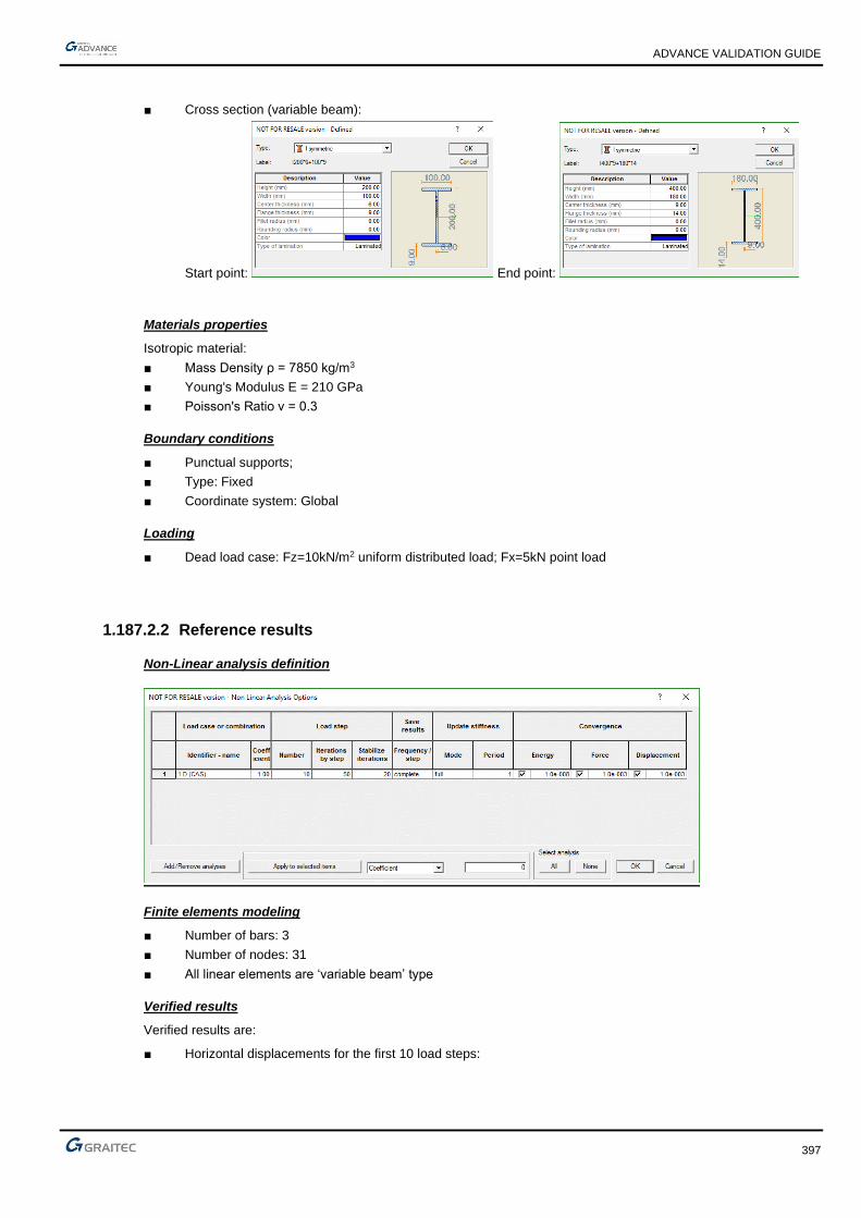
ADVANCE VALIDATION GUIDE
397
■ Cross section (variable beam):
Start point: End point:
Materials properties
Isotropic material:
■ Mass Density ρ = 7850 kg/m3
■ Young's Modulus E = 210 GPa
■ Poisson's Ratio ν = 0.3
Boundary conditions
■ Punctual supports;
■ Type: Fixed
■ Coordinate system: Global
Loading
■ Dead load case: Fz=10kN/m2 uniform distributed load; Fx=5kN point load
1.187.2.2 Reference results
Non-Linear analysis definition
Finite elements modeling
■ Number of bars: 3
■ Number of nodes: 31
■ All linear elements are ‘variable beam’ type
Verified results
Verified results are:
■ Horizontal displacements for the first 10 load steps:

ADVANCE VALIDATION GUIDE
398
Comparison
Results are compared with results coming from the identical model created and calculated by using another independent FEM software.
1.187.2.3 Calculated results
Node numbering in AD
Description Symbol Unit AD 2019 Reference Difference
displacement node 21 Dx mm 0.327 0.324 0.92%
displacement node 21 Dx mm 0.655 0.649 0.92%
displacement node 21 Dx mm 0.983 0.973 1.02%
displacement node 21 Dx mm 1.311 1.299 0.92%
displacement node 21 Dx mm 1.640 1.624 0.98%
displacement node 21 Dx mm 1.969 1.95 0.96%
displacement node 21 Dx mm 2.299 2.277 0.96%
displacement node 21 Dx mm 2.629 2.603 0.99%
displacement node 21 Dx mm 2.960 2.93 1.01%
displacement node 21 Dx mm 3.291 3.258 1.00%

ADVANCE VALIDATION GUIDE
399
1.188 NL static analysis on strut element type - Verifying nodal displacements and forces in strut after performing NL static analysis
Test ID: 6617
Test status: Passed
1.188.1 Description
The test verifies the response of a braced frame subject to horizontal point load after performing NL static analysis on the model. The structure consists of S beam to define the frame and a diagonal strut. The frame is fixed at the base by two point supports. Horizontal point force is applied at the beam column intersection. Horizontal nodes displacements and axial forces in the strut element resulted from the 10 steps load application are verified.
1.189 NL static analysis on membrane – Verifying nodal displacements and forces in the planar element after performing NL static analysis
Test ID: 6618
Test status: Passed
1.189.1 Description
The test verifies the response of a membrane subject to uniform distributed load after performing Non-Linear static analysis. The membrane has 20cm thickness and is made of C25/30 concrete and is fixed at the base by a linear support. Uniform distributed load is applied on the top edge with a value of 50kN, gravitationally. Forces in the membrane and nodal displacements are verified from the Non-Linear static case.
1.190 Verifying the behavior of elastic rotational releases on both ends of a beam in static analysis (100kNm/deg)
Test ID: 6619
Test status: Passed
1.190.1 Description
The model comprises of two frames. One frame having elements with default fixed ends and the other having applied an elastic rotational release at both ends. The cross-section of the linear elements is Rectangular 20x30cm and the material is Reinforced Concrete C25/30. The rigidity applied to the rotation of the beam end nodes is 100kNm/degree. Both frames are subjected to a vertical distributed load of -10kN/m.
1.191 Verifying the behavior of elastic displacement release on one end of a beam in static analysis (200kN/m)
Test ID: 6620
Test status: Passed
1.191.1 Description
The model comprises of two frames. One frame having elements with default fixed ends and the other having applied an elastic displacement release at the start extremity (1). The cross-section of the linear elements is Rectangular 20x30cm and the material is Reinforced Concrete C25/30. The rigidity applied to the displacement of the beam end node is 200kN/m. Both frames are subjected to a horizontal concentrated load of 100kN at the beams end.

ADVANCE VALIDATION GUIDE
400
1.192 Torsors/Groups of walls with rotated local axes, z+ and z- (load 10kN/m at top on z direction) - check MX, MY / Group
Test ID: 6621
Test status: Passed
1.192.1 Description
There are 4 walls with rotated local axes and z in same direction in one Group and 4 walls with rotated local axes and z in same direction in the second group, but with z in the opposite sense than the first group. All walls are: 3x5m, 20cm thick shell elements, fixed supported at the base and free on all other edges, loaded at top with a linear 10kN/m load on the local z direction and same sense. All walls are in the same plane, perpendicular to global XOY and at an angle about the XOZ plane.
Check the results for MX/Group and TY/Group (Global coordinate system): should be identical for the two groups, independent of the local axes position on the individual walls.
1.193 Torsors/Groups of walls with rotated local axes, z+ and z- (load 10kN/m at top on z direction) - check MX, TY / Group, Mf and Tyz
Test ID: 6622
Test status: Passed
1.193.1 Description
There are 4 walls with rotated local axes and z in same direction in one Group and 4 walls with rotated local axes and z in same direction in the second group, but with z in the opposite sense than the first group. All walls are: 3x5m, 20cm thick shell elements, fixed supported at the base and free on all other edges, loaded at top with a linear 10kN/m load on the local z direction and same sense. All walls are in the same plane, perpendicular to global XOY and parallel to the XOZ plane.
Check the results for MX/Group and TY/Group (Global coordinate system), should be identical for the two groups, independent of the local axes position on the individual walls, Mf and Tyz (local coordinate system).
1.194 Torsors/Groups of walls with rotated local axes, z+ and z- (load 10kN at top in the walls plane) - check MY, TX / Group, Mz, Txy
Test ID: 6623
Test status: Passed
1.194.1 Description
There are 4 walls with rotated local axes and z in same direction in one Group and 4 walls with rotated local axes and z in same direction in the second group, but with z in the opposite sense than the first group. All walls are: 3x5m, 20cm thick shell elements, fixed supported at the base and free on all other edges, loaded at top with a concentrated 10kN load in the walls plane and same sense. All walls are in the same plane, perpendicular to global XOY and parallel to the XOZ plane.
Check the results for MY/Group and TX/Group (Global coordinate system), should be identical for the two groups, independent of the local axes position on the individual walls, Mz and Txy (local coordinate system).

ADVANCE VALIDATION GUIDE
401
1.195 Nonlinear static analysis on 3D model with rigid diaphragm defined as shell with DOF constraint subjected to horizontal and gravitational loads
Test ID: 6624
Test status: Passed
1.195.1 Description
The test verifies the response of a 3D structure after performing Nonlinear static analysis. The model consists of linear elements and a planar element defined as shell. To simulate the rigid diaphragm effect, a DOF constraint is imposed having master node placed in the center of the shell (center of rigidity) and slave nodes in the mesh points. The master-slave connection is defined to have Tx, Ty and Rz restrained.
The linear elements have 20x30 cm cross section, while the shell has 20 cm thickness. All elements are made of C25/30 concrete. The structure is subjected to horizontal X and Y linear load and gravitational planar load.
Nodes displacements and forces on the linear and planar elements are verified after performing Nonlinear static analysis on the model. Results from 10 steps are verified and compared with results obtained from another independent software.
1.195.2 Background
1.195.2.1 Model description
■ 3D structure – linear and planar elements
■ Element type: shell, S beam
■ Analysis type: Non-Linear analysis
Units
Metric System
Geometry
■ Base length: L = 8.0 m
■ Base width: l = 5.0 m
■ Height: H = 5.0 m
■ Cross sections:

ADVANCE VALIDATION GUIDE
402
columns: beams:
Materials properties
C25/30 concrete:
■ Mass Density: ρ = 2500 kg/m3
■ Young's Modulus: E = 31.47 GPa
■ Poisson's Ratio: ν = 0.2
Boundary conditions
■ Punctual supports;
■ Type: Fixed
■ Coordinate system: Global
Loading
■ Dead load case: Fx = 100 kN/m, Fy = -100 kN/m linear load
■ Dead load case: Fz = -20 kN/m2 planar load
DOF constraint definition:
■ Master node defined in the center of the planar element (center of rigidity)
■ Slave nodes defined on each mesh points (0.5 m mesh size)

ADVANCE VALIDATION GUIDE
403
1.195.2.2 Reference results
Non-Linear analysis definition
Finite elements modeling
■ Number of bars: 8
■ Number of planar elements: 1
■ Number of nodes: 227
Verified results
Verified results are:
■ Displacements for the first 10 load steps;
■ Forces in linear elements;
■ Forces in planar elements.
Comparison
Results are compared with results coming from the identical model created and calculated by using another independent FEM software.
Calculated results
Mesh model preview

ADVANCE VALIDATION GUIDE
404
Description Symbol Unit Step Position AD 2019 Reference Difference
Axial force in column 21 Fx kN
1 top 52.01 52.66 1.25%
Axial force in column 21 Fx kN bottom 53.41 53.41 0.00%
Axial force in column 21 Fx kN
2 top 104.39 105.74 1.29%
Axial force in column 21 Fx kN bottom 106.45 107.24 0.74%
Axial force in column 21 Fx kN
3 top 156.77 159.28 1.60%
Axial force in column 21 Fx kN bottom 159.49 161.53 1.28%
Axial force in column 21 Fx kN
4 top 209.15 213.26 1.97%
Axial force in column 21 Fx kN bottom 212.54 216.26 1.75%
Axial force in column 21 Fx kN
5 top 261.53 267.73 2.37%
Axial force in column 21 Fx kN bottom 265.58 271.48 2.22%
Axial force in column 21 Fx kN
6 top 313.91 322.68 2.79%
Axial force in column 21 Fx kN bottom 318.62 327.18 2.69%
Axial force in column 21 Fx kN
7 top 366.29 378.15 3.24%
Axial force in column 21 Fx kN bottom 371.66 383.4 3.16%
Axial force in column 21 Fx kN
8 top 418.67 434.14 3.70%
Axial force in column 21 Fx kN bottom 424.7 440.14 3.64%
Axial force in column 21 Fx kN
9 top 471.05 490.68 4.17%
Axial force in column 21 Fx kN bottom 477.75 497.43 4.12%
Axial force in column 21 Fx kN
10 top 523.43 547.79 4.65%
Axial force in column 21 Fx kN bottom 530.79 555.29 4.62%
Description Step Symbol Unit
AD 2019 Reference Difference
Displacement of node 57 10 Dx cm 11.74 11.75 0.09 %
Displacement of node 57 10 Dy cm 36.39 36.42 0.08 %
Displacement of node 57 10 Dz cm 0.14 0.14 0.00 %

ADVANCE VALIDATION GUIDE
405
1.196 NL static analysis on 3D model with windwall defined as rigid diaphragm subject to horizontal and gravitational loads.
Test ID: 6625
Test status: Passed
1.196.1 Description
The test verifies the response of a 3D structure after performing Non-Linear static analysis. The model consists of linear elements and a windwall defined as rigid diaphragm. Self weight is disabled for the windwall. The linear elements have 20x30cm cross section, while the windwall has 20cm thickness.
All elements are made of C25/30 concrete. The structure is subject to horizontal X and Y linear load and gravitational planar load. Nodes displacements and forces on the linear elements are verified after performing Non-Linear static analysis on the model. Results from 10 steps are verified.
1.197 Torsors/Groups of walls with rotated local axes, z+ and z- (load 10kN at top at angle with walls plane) - check Mz, Mf, Txy, Tyz
Test ID: 6626
Test status: Passed
1.197.1 Description
There are 4 walls with rotated local axes and z in same direction in one Group and 4 walls with rotated local axes and z in same direction in the second group, but with z in the opposite sense than the first group. All walls are: 3x5m, 20cm thick shell elements, fixed supported at the base and free on all other edges, loaded at top with a concentrated 10kN load at angle with the walls plane. All walls are in the same plane, perpendicular to global XOY and at an angle relative to the XOZ plane.
Check the results for MX/Group, MY/Group and TX/Group (Global coordinate system), should be identical for the two groups, independent of the local axes position on the individual walls, Mz, Mf, Txy and Tyz (local coordinate system).
1.198 Torsors/Groups of walls with rotated local axes, z+ and z- (load 10kN at top in the walls plane) - check MX, TY / Group, Mz and Txy
Test ID: 6627
Test status: Passed
1.198.1 Description
There are 4 walls with rotated local axes and z in same direction in one Group and 4 walls with rotated local axes and z in same direction in the second group, but with z in the opposite sense than the first group. All walls are: 3x5m, 20cm thick shell elements, fixed supported at the base and free on all other edges, loaded at top with a concentrated 10kN load in the walls plane. All walls are in the same plane, perpendicular to global XOY and parallel to the YOZ plane.
Check the results for MX/Group and TY/Group (Global coordinate system), should be identical for the two groups, independent of the local axes position on the individual walls, Mz and Txy (local coordinate system).

ADVANCE VALIDATION GUIDE
406
1.199 Torsors/Groups of walls with rotated local axes, z+ and z- (load 10kN/m at top on z direction) - check MY, TX, Mf and Tyz
Test ID: 6628
Test status: Passed
1.199.1 Description
There are 4 walls with rotated local axes and z in same direction in one Group and 4 walls with rotated local axes and z in same direction in the second group, but with z in the opposite sense than the first group. All walls are: 3x5m, 20cm thick shell elements, fixed supported at the base and free on all other edges, loaded at top with a linear 10kN/m load on the local z direction and same sense. All walls are in the same plane, perpendicular to global XOY and parallel to the YOZ plane.
Check the results for MY/Group and TX/Group (Global coordinate system), should be identical for the two groups, independent of the local axes position on the individual walls, Mf and Tyz (local coordinate system).
1.200 Verifying the resultant forces on single walls
Test ID: 6692
Test status: Passed
1.200.1 Description
The test verifies the sign of the resultant forces generated on single walls. The walls have different local axes.

ADVANCE VALIDATION GUIDE
407
1.201 Verifying the resultant forces on a group of walls
Test ID: 6693
Test status: Passed
1.201.1 Description
The test verifies the generation of the resultant forces on a group of walls. The model consists of two perpendicular reinforced concrete walls. The walls have fixed linear supports at the base and linear loads applied at the top. The resultant forces generated by Advance Design on the group of walls are validated by hand calculation – the resultant forces are derived from the individual forces on each wall.
1.201.2 Background
1.201.2.1 Model description
■ 3D structure
■ Element type: Planar - shell
■ Analysis type: Linear analysis
■ Software version: AD2020 build 15107
■ Results are validated by hand calculation.
Units
Metric System
Geometry
■ Length of wall 1=3.00m
■ Length of wall 2=6.00m
■ Height of wall 1 and 2=5.0 m
Linear elements
■ Type: shell

ADVANCE VALIDATION GUIDE
408
■ Thickness= 20 cm
Materials properties
Isotropic material, C25/30:
■ Mass Density ρ = 2500 kg/m3
■ Young's Modulus E = 31.475 GPa
■ Poisson's Ratio ν = 0.2
Boundary conditions
■ Linear supports;
■ Type: Fixed
■ Coordinate system: Global
Loading
■ Live load case: Fz=-3.33kN/m uniform distributed load – top of wall 1 and 2
Fx= 3.33kN/m uniform distributed load – top of wall 2
Fy= 3.33kN/m uniform distributed load – top of wall 1
1.201.2.2 Reference results
Finite elements modeling
■ Number of planar elements: 2
■ Number of linear supports: 2
■ Mesh Type: Delauney
■ Mesh element size: 0.75 m
Verified results
Verified results are:
■ Resultant forces on the group of walls (wall 1+2)
NZ / Goup resultant axial force and MX / Group -resultant Mx bending moment on the group of walls

ADVANCE VALIDATION GUIDE
409
Description Value Unit
MY / Group up 7.03 kN/m
MY / Group down 91.42 kN/m
MX / Group up -3.59 kN/m
MX / Group down -45.57 kN/m
TY / Group up 10.00 kN
TY / Group down 9.85 kN
TX / Group up 20.00 kN
TX / Group down 19.75 kN
NZ / Group up -29.87 kN
NZ / Group down -29.94 kN
Resultant forces on the group of walls – on global coordinates
Comparison
The resultant forces generated by Advance Design on the group of walls are compared with those obtained by hand calculation – the resultant forces are derived from the individual forces on each wall.
1.201.2.3 Calculated results
The resultant forces on each wall are used as input data.
NZ axial force and MX bending moment on wall 2 – on global coordinates
Description Wall 1 Wall 2 Unit
MY / up 1.37 3.71 kN/m
MY / down 43.54 25.86 kN/m
MX / up -2.05 -5.43 kN/m
MX / down 1.33 -90.95 kN/m
TY / up 5.76 4.24 kN
TY / down -1.50 11.34 kN
TX / up 9.60 10.40 kN
TX / down 11.77 7.98 kN
NZ / up -11.25 -18.61 kN
NZ / down -24.66 -5.28 kN
Resultant forces on wall 1 and wall 2 – on global coordinates

ADVANCE VALIDATION GUIDE
410
Firstly, the center of weight, about which the resultant forces are computed, for the group of the walls is calculated. Then, the corresponding lever arm for the axial forces of the walls.
Center of weight of the group of walls and lever arm of the axial forces
MY/Group_up = MY/Group_up_wall1 + MY/Group_up_wall1 + NZ_up_wall1*x_w1 + NZ_up_wall2*x_w2 =
= 1.37kN/m + 3.71kN/m - (-)11.25kN *1m + (-)18.61kN * 0.5m = 7.03 kN/m
MX/Group_up= MX/Group_up_wall1 + MX/Group_up_wall1 + NZ_up_wall1*y_w1 + NZ_up_wall2*y_w2
= -2.05kN/m + (-)5.43kN/m - (-11.25)kN*2m + (-)18.61kN/m*1m = -3.59 kN/m
TY/Group_up = TY/Group_up_wall1 + TY/Group_up_wall2 = 5.76kN + 4.24kN = 10 kN
TX/Group_up = TX/Group_up wall1 + TX/Group_up_wall2 = 9.60kN + 10.40kN = 20 kN
NZ/Group_up = NZ/Group_up_wall1 + NZ/Group_up_wall2 = -11.25kN + (-)18.61kN = -29.86kN
Where:
x_w1 = (-1) and is the projection on X of the distance between the resultant axial resultant N on wall 1 (NZ_wall1) and the geometrical centre of the group
x_w2 = 0.5 and is the projection on X of the distance between the resultant axial resultant N on wall 2 (NZ_wall2) and the geometrical centre of the group
y_w1 = (-2) and is the projection on Y of the distance between the resultant axial resultant N on wall 1 (NZ_wall1) and the geometrical centre of the group
y_w2 = 1 and is the projection on Y of the distance between the resultant axial resultant N on wall 2 (NZ_wall2) and the geometrical centre of the group

ADVANCE VALIDATION GUIDE
411
It is done similarly for the base of the group of walls, finally obtaining:
Description AD Hand
calculation Unit
Deviation
MY / up 7.03 7.03 kN/m 0.07%
MY / down 91.42 91.42 kN/m 0.00%
MX / up -3.59 -3.59 kN/m 0.00%
MX / down -45.57 -45.58 kN/m -0.02%
TY / up 10.00 10.00 kN 0.00%
TY / down 9.85 9.84 kN 0.10%
TX / up 20.00 20.00 kN 0.00%
TX / down 19.75 19.75 kN 0.00%
NZ / up -29.87 -29.86 kN 0.03%
NZ / down -29.94 -29.94 kN 0.00%
Verification of the resultant forces on a group of walls

ADVANCE VALIDATION GUIDE
412
1.202 Verifying the sum of actions on supports
Test ID: 6694
Test status: Passed
1.202.1 Description
The model consists of a single storey reinforced concrete structure, having 4 column: 2 of 4 meters and 2 of 5 meters. The structure is loaded at the top by two lateral loads, one on each directions. The resulting bending moments on the supports are verified.
1.203 Pushover Analysis - Verifying the Pushover load distribution - Concentrated
Test ID: 6698
Test status: Passed
1.203.1 Description
The model consists of a 3-storeys reinforced concrete structure. The storeys have different areas.
The structure is loaded by dead loads (self weight and applied loads), live loads, wind loads and snow loads. Seismic load cases are also generated.
Two Pushover Load Types are defined:
- Load Type 1 - the distribution is set to "concentrated" and the point of application to "center of mass". The maximum total lateral load is set to "Percentage of the total gravity loads"
- Load Type 2 - the distribution is set to "concentrated" and the point of application to "surface distributed on slab". The maximum total lateral load is set to "Percentage of the total gravity loads"
For each load type, the "Maximum total lateral load" and the loads distributed at each storey are verified wtih analytical results.
1.204 Pushover Analysis - Verifying the Pushover load distribution - Uniform
Test ID: 6699
Test status: Passed
1.204.1 Description
The model consists of a 3-storeys reinforced concrete structure. The storeys have different areas.
The structure is loaded by dead loads (self weight and applied loads), live loads, wind loads and snow loads. Seismic load cases are also generated.
Two Pushover Load Types are defined:
- Load Type 1 - the distribution is set to "uniform" and the point of application to "center of mass". The maximum total lateral load is set to "Percentage of the total gravity loads"
- Load Type 2 - the distribution is set to "uniform" and the point of application to "surface distributed on slab". The maximum total lateral load is set to "Percentage of the total gravity loads"
For each load type, the "Maximum total lateral load" and the loads distributed at each storey are verified wtih analytical results.

ADVANCE VALIDATION GUIDE
413
1.205 Pushover Analysis - Verifying the Pushover load distribution - Triangular
Test ID: 6700
Test status: Passed
1.205.1 Description
The model consists of a 3-storeys reinforced concrete structure. The storeys have different areas.
The structure is loaded by dead loads (self weight and applied loads), live loads, wind loads and snow loads. Seismic load cases are also generated.
Two Pushover Load Types are defined:
- Load Type 1 - the distribution is set to "triangular" and the point of application to "center of mass". The maximum total lateral load is set to "Percentage of the total gravity loads"
- Load Type 2 - the distribution is set to "triangular" and the point of application to "surface distributed on slab". The maximum total lateral load is set to "Percentage of the total gravity loads"
For each load type, the "Maximum total lateral load" and the loads distributed at each storey are verified wtih analytical results.
1.206 Pushover Analysis - Verifying the Pushover load distribution - Parabolic
Test ID: 6701
Test status: Passed
1.206.1 Description
The model consists of a 3-storeys reinforced concrete structure. The storeys have different areas.
The structure is loaded by dead loads (self weight and applied loads), live loads, wind loads and snow loads. Seismic load cases are also generated.
Two Pushover Load Types are defined:
- Load Type 1 - the distribution is set to "parabolic" and the point of application to "center of mass". The maximum total lateral load is set to "Percentage of the total gravity loads"
- Load Type 2 - the distribution is set to "parabolic" and the point of application to "surface distributed on slab". The maximum total lateral load is set to "Percentage of the total gravity loads"
For each load type, the "Maximum total lateral load" and the loads distributed at each storey are verified wtih analytical results.
1.207 Pushover Analysis - Verifying the maximum total lateral load - Seismic base shear force
Test ID: 6702
Test status: Passed
1.207.1 Description
The model consists of a 3-storeys reinforced concrete structure. The storeys have different areas.
The structure is loaded by dead loads (self weight and applied loads), live loads, wind loads and snow loads. Seismic load cases are also generated.
Two Pushover Load Types are defined:
- Load Type 1 - the distribution is set to "uniform" and the point of application to "center of mass". The maximum total lateral load is set to "Seismic base shear force on X"
- Load Type 2 - the distribution is set to "uniform" and the point of application to "surface distributed on slab". The maximum total lateral load is set to "Seismic base shear force on Y"
For each load type, the "Maximum total lateral load" is verified.

ADVANCE VALIDATION GUIDE
414
1.208 EC3/ NF EN 1993-1-1/NA - France: Pushover Analysis - Verifying the status of a steel FEMA flexural plastic hinge
Test ID: 6738
Test status: Passed
1.208.1 Description
The model consists of a steel S235 linear element, having an HEB300 cross-section. The element is fixed supported at both ends.
A FEMA plastic hinge is defined on Ry and Rz DOF''s only at one end in order to prevent instability when the plastic hinge is developed.
Two Pushover load cases are defined:
- a load case on the X direction with a user defined concentrated load of 5000kN applied at midspan
- a load case on the Y direction with a user defined concentrated load of 2500kN applied at midspan
The Pushover Analysis is defined with 50 steps.
The aim of the test is to verify the plastic hinge rotation at each step and the sequence of plastic hinge statuses. The results are validated with an independent software.
During the test, the Pushover analysis is run with and without the Steel design. The "Flexural plastic hinges status by load step" report is generated for each run.
1.209 AISC: Pushover Analysis - Verifying the status of a steel FEMA flexural plastic hinge
Test ID: 6739
Test status: Passed
1.209.1 Description
The model consists of a steel S235 linear element, having an HEB300 cross-section. The element is fixed supported at both ends.
A FEMA plastic hinge is defined on Ry and Rz DOF''s only at one end in order to prevent instability when the plastic hinge is developed.
Two Pushover load cases are defined:
- a load case on the X direction with a user defined concentrated load of 5000kN applied at midspan
- a load case on the Y direction with a user defined concentrated load of 2500kN applied at midspan
The Pushover Analysis is defined with 50 steps.
The aim of the test is to verify the plastic hinge rotation at each step and the sequence of plastic hinge statuses. The results are validated with an independent software.
During the test, the Pushover analysis is run with and without the Steel design. The "Flexural plastic hinges status by load step" report is generated for each run.

ADVANCE VALIDATION GUIDE
415
1.210 EC3/ NF EN1993-1-1/NA France: Pushover Analysis - Verifying the limit states and status of a steel EC8-3 flexural plastic hinge
Test ID: 6740
Test status: Passed
1.210.1 Description
The model consists of two identical steel S235 linear elements, having an HEB300 cross-section. The elements are fixed supported at both ends.
For both elements an EC8-3 plastic hinge is defined on Ry and Rz DOF''s only at one end in order to prevent instability when the plastic hinge is developed.
For one element the cross-section class is defined as class 1, while for the other it is defined as class 2.
Two Pushover load cases are defined:
- a load case on the X direction with a user defined concentrated load of 5000kN applied at midspan
- a load case on the Y direction with a user defined concentrated load of 2500kN applied at midspan
The Pushover Analysis is defined with 50 steps.
The aim of the test is to verify the limit states, the plastic hinge rotation at each step and the sequence of plastic hinge statuses. The results are validated with an independent software.
During the test, the Pushover analysis is run with and without the Steel design. The "Flexural plastic hinges status by load step" report is generated for each run.
1.211 AISC: Pushover Analysis - Verifying the status of a steel EC8-3 flexural plastic hinge
Test ID: 6741
Test status: Passed
1.211.1 Description
The model consists of a steel S235 linear element, having an HEB300 cross-section. The element is fixed supported at both ends.
An EC8-3 plastic hinge is defined on Ry and Rz DOF''s only at one end in order to prevent instability when the plastic hinge is developed.
Two Pushover load cases are defined:
- a load case on the X direction with a user defined concentrated load of 5000kN applied at midspan
- a load case on the Y direction with a user defined concentrated load of 2500kN applied at midspan
The Pushover Analysis is defined with 50 steps.
The aim of the test is to verify the plastic hinge rotation at each step and the sequence of plastic hinge statuses. The results are validated with an independent software.
During the test, the Pushover analysis is run with and without the Steel design. The "Flexural plastic hinges status by load step" report is generated for each run

ADVANCE VALIDATION GUIDE
416
1.212 AISC: Pushover Analysis - Verifying the properties and limit states of the FEMA356 steel flexural plastic hinges - without steel design
Test ID: 6742
Test status: Passed
1.212.1 Description
The aim of the test is to verify the plastic hinge properties (yield bending moments and yield rotations) and the limit states of automatically defined FEMA356 steel plastic hinges.
The model contains 3 sets of 6 identical steel linear elements. There are 6 types of plastic hinges, each of them having 3 branches - depending on the cross-section and material properties.
Hence, the model contains:
- 6 elements having the HEB300 cross-section - corresponding to the branch A of the plastic hinges, according to the FEMA356 tables
- 6 elements having the HP360x84 cross-section - corresponding to the branch B of the plastic hinges, according to the FEMA356 tables
- 6 elements having the HP360x84 cross-section - corresponding to the branch C of the plastic hinges, according to the FEMA356 tables
Except the different cross-section, all the elements are identical. They are made out of S235 steel, have a length of five meters and are fixed supported at both ends.
For each element a different plastic hinge type is defined on Ry and Rz DOF''s only at one end in order to prevent instability when the plastic hinge is developed.
Two Pushover load cases are defined:
- a load case on the X direction with a user defined concentrated load of 5000kN applied at midspan
- a load case on the Y direction with a user defined concentrated load of 2500kN applied at midspan
The "Flexural plastic hinges status by load step" report is verified. The plastic hinge properties (yield bending moments and yield rotations) and the limit states are validated by hand calculations.

ADVANCE VALIDATION GUIDE
417
1.213 AISC: Pushover Analysis - Verifying the properties and limit states of the FEMA356 steel flexural plastic hinges - with steel design
Test ID: 6743
Test status: Passed
1.213.1 Description
The aim of the test is to verify the plastic hinge properties (yield bending moments and yield rotations) and the limit states of automatically defined FEMA356 steel plastic hinges.
The model contains 3 sets of 6 identical steel linear elements. There are 6 types of plastic hinges, each of them having 3 branches - depending on the cross-section and material properties.
Hence, the model contains:
- 6 elements having the HEB300 cross-section - corresponding to the branch A of the plastic hinges, according to the FEMA356 tables
- 6 elements having the HP360x84 cross-section - corresponding to the branch B of the plastic hinges, according to the FEMA356 tables
- 6 elements having the HP360x84 cross-section - corresponding to the branch C of the plastic hinges, according to the FEMA356 tables
Except the different cross-section, all the elements are identical. They are made out of S235 steel, have a length of five meters and are fixed supported at both ends.
For each element a different plastic hinge type is defined on Ry and Rz DOF''s only at one end in order to prevent instability when the plastic hinge is developed.
Two Pushover load cases are defined:
- a load case on the X direction with a user defined concentrated load of 5000kN applied at midspan
- a load case on the Y direction with a user defined concentrated load of 2500kN applied at midspan
The "Flexural plastic hinges status by load step" report is verified. The plastic hinge properties (yield bending moments and yield rotations) and the limit states are validated by hand calculations.

ADVANCE VALIDATION GUIDE
418
1.214 EC3/NF EN 1993-1-1/NA: Pushover Analysis - Verifying the properties and limit states of the FEMA356 steel flexural plastic hinges - without steel design
Test ID: 6744
Test status: Passed
1.214.1 Description
The aim of the test is to verify the plastic hinge properties (yield bending moments and yield rotations) and the limit states of automatically defined FEMA356 steel plastic hinges.
The model contains 3 sets of 6 identical steel linear elements. There are 6 types of plastic hinges, each of them having 3 branches - depending on the cross-section and material properties.
Hence, the model contains:
- 6 elements having the HEB300 cross-section - corresponding to the branch A of the plastic hinges, according to the FEMA356 tables
- 6 elements having the HP360x84 cross-section - corresponding to the branch B of the plastic hinges, according to the FEMA356 tables
- 6 elements having the HP360x84 cross-section - corresponding to the branch C of the plastic hinges, according to the FEMA356 tables
Except the different cross-section, all the elements are identical. They are made out of S235 steel, have a length of five meters and are fixed supported at both ends.
For each element a different plastic hinge type is defined on Ry and Rz DOF''s only at one end in order to prevent instability when the plastic hinge is developed.
Two Pushover load cases are defined:
- a load case on the X direction with a user defined concentrated load of 5000kN applied at midspan
- a load case on the Y direction with a user defined concentrated load of 2500kN applied at midspan
The "Flexural plastic hinges status by load step" report is verified. The plastic hinge properties (yield bending moments and yield rotations) and the limit states are validated by hand calculations.

ADVANCE VALIDATION GUIDE
419
1.215 EC3/NF EN 1993-1-1/NA: Pushover Analysis - Verifying the properties and limit states of the FEMA356 steel flexural plastic hinges - with steel design
Test ID: 6745
Test status: Passed
1.215.1 Description
The aim of the test is to verify the plastic hinge properties (yield bending moments and yield rotations) and the limit states of automatically defined FEMA356 steel plastic hinges.
he model contains 3 sets of 6 identical steel linear elements. There are 6 types of plastic hinges, each of them having 3 branches - depending on the cross-section and material properties.
Hence, the model contains:
- 6 elements having the HEB300 cross-section - corresponding to the branch A of the plastic hinges, according to the FEMA356 tables
- 6 elements having the HP360x84 cross-section - corresponding to the branch B of the plastic hinges, according to the FEMA356 tables
- 6 elements having the HP360x84 cross-section - corresponding to the branch C of the plastic hinges, according to the FEMA356 tables
Except the different cross-section, all the elements are identical. They are made out of S235 steel, have a length of five meters and are fixed supported at both ends.
For each element a different plastic hinge type is defined on Ry and Rz DOF''s only at one end in order to prevent instability when the plastic hinge is developed.
Two Pushover load cases are defined:
- a load case on the X direction with a user defined concentrated load of 5000kN applied at midspan
- a load case on the Y direction with a user defined concentrated load of 2500kN applied at midspan
The "Flexural plastic hinges status by load step" report is verified. The plastic hinge properties (yield bending moments and yield rotations) and the limit states are validated by hand calculations.

ADVANCE VALIDATION GUIDE
420
1.216 AISC: Pushover Analysis - Verifying the properties and limit states of the FEMA356 steel axial plastic hinges
Test ID: 6746
Test status: Passed
1.216.1 Description
The model consists of two identical S235 steel frames. Each one having 2 columns, a beam and a diagonal bracing. The columns and beams have an HEB300 cross-section, while the diagonal bracing has an IPE120 cross-section.
For each frame, on the diagonal bracing, a FEMA356 plastic hinge is defined on the Tx direction. The plastic hinge on the first frame is defined as primary, while on the second one as secondary.
Two Pushover load cases are defined:
- a load case on the X+ direction with a user defined concentrated load applied at the top of each frame
- a load case on the X- direction with a user defined concentrated load applied at the top of each frame
The Pushover Analysis is defined with 20 steps.
The aim of the test is to verify the plastic hinge properties (yield axial forces and yield deformations), the limit states of automatically defined FEMA356 steel plastic hinges and the sequence of plastic hige statuses. The results are validated with an independent software.
The "Axial plastic hinges status by load step" report is verified. The results are validated with an independent software.
1.217 EC3/NF EN 1993-1-1/NA: Pushover Analysis - Verifying the properties and limit states of the FEMA356 steel axial plastic hinges
Test ID: 6747
Test status: Passed
1.217.1 Description
The model consists of two identical S235 steel frames. Each one having 2 columns, a beam and a diagonal bracing. The columns and beams have an HEB300 cross-section, while the diagonal bracing has an IPE120 cross-section.
For each frame, on the diagonal bracing, a FEMA356 plastic hinge is defined on the Tx direction. The plastic hinge on the first frame is defined as primary, while on the second one as secondary.
Two Pushover load cases are defined:
- a load case on the X+ direction with a user defined concentrated load applied at the top of each frame
- a load case on the X- direction with a user defined concentrated load applied at the top of each frame
The Pushover Analysis is defined with 20 steps.
The aim of the test is to verify the plastic hinge properties (yield axial forces and yield deformations), the limit states of automatically defined FEMA356 steel plastic hinges and the sequence of plastic hige statuses. The results are validated with an independent software.
The "Axial plastic hinges status by load step" report is verified. The results are validated with an independent software.

ADVANCE VALIDATION GUIDE
421
1.218 AISC: Pushover Analysis - Verifying the properties and limit states of the EC8-3 steel axial plastic hinges
Test ID: 6748
Test status: Passed
1.218.1 Description
The model consists steel frame having 2 columns, a beam and a diagonal bracing, made out of S235 steel. The columns and the beam have a HEB300 cross-section, while the diagonal bracing has an IPE120 cross-section.
On the diagonal bracing, an EC8-3 plastic hinge is defined on the Tx direction.
Two Pushover load cases are defined:
- a load case on the X+ direction with a user defined concentrated load applied at the top of the frame
- a load case on the X- direction with a user defined concentrated load applied at the top of the frame
The Pushover Analysis is defined with 20 steps.
The aim of the test is to verify the plastic hinge properties (yield axial forces and yield deformations), the limit states of the automatically defined EC8-3 steel plastic hinge and the sequence of plastic hinge statuses. The results are validated with an independent software.
The "Axial plastic hinges status by load step" report is verified. The results are validated with an independent software.
1.219 EC3/NF EN 1993-1-1/NA: Pushover Analysis - Verifying the properties and limit states of the EC8-3 steel axial plastic hinges
Test ID: 6749
Test status: Passed
1.219.1 Description
The model consists of two identical S235 steel frames. Each one having 2 columns, a beam and a diagonal bracing. The columns and beams have a HEB300 cross-section, while the diagonal bracing has an IPE120 cross-section.
For each frame, on the diagonal bracing, an EC8-3 plastic hinge is defined on the Tx direction. For the first frame, the diagonal bracing has the cross-section class 1. For the second frame, the diagonal bracing has the cross-section class 2.
Two Pushover load cases are defined:
- a load case on the X+ direction with a user defined concentrated load applied at the top of each frame
- a load case on the X- direction with a user defined concentrated load applied at the top of each frame
The Pushover Analysis is defined with 20 steps.
The aim of the test is to verify the plastic hinge properties (yield axial forces and yield deformations), the limit states of automatically defined EC8-3 steel plastic hinges and the sequence of plastic hinge statuses. The results are validated with an independent software.
The "Axial plastic hinges status by load step" report is verified. The results are validated with an independent software.

ADVANCE VALIDATION GUIDE
422
1.220 AISC: Pushover Analysis - Verifying the pushover curve and rotations of the plastic hinges for a two storey steel frame
Test ID: 6750
Test status: Passed
1.220.1 Description
The model consists of a two storeys steel frame, made out of ASTM A992 steel. The two storeys are identical, having two columns (one of them IPE300 and the other one IPE270) and a beam (IPE300). Both the columns and the beams have a length of 5m.
FEMA356 plastic hinges are defined for all elements at both ends.
A user-defined pushover load cases is defined and a concentrated load of 70kN is applied at the top of each store.
The Pushover Analysis is defined with 50 steps.
The aim of the test is to verify:
- the pushover curve (force-displacement curve)
- the hinge rotations at each step
- the sequences of hinge statuses
- the overstrength ratio
The "Flexural plastic hinges status by load step" and the "Overstrength ratio" reports are verified. The results are validated with an independent software.
1.221 EC2/NF EN 1992-1-1/NA: Pushover Analysis - Verifying the pushover curve and rotations of the EC8-3 plastic hinges for a four storey reinforced concrete frame
Test ID: 6751
Test status: Passed
1.221.1 Description
The model consists of a four storeys reinforced concrete frame having two bays, and made out of C25/30 concrete. The storeys are identical. The columns have a length of 4m and the beams a length of 7m and 8m.
For all elements, at both ends, EC8-3 plastic hinges are defined on the Ry direction.
A user-defined pushover load case is defined and concentrated loads are applied at each storey.
The Pushover Analysis is defined with 50 steps.
The aim of the test is to verify the plastic hinge properties (yield bending moments and yield rotations), the limit states of automatically defined FEMA356 steel plastic hinges and the pushover curve.
The "Flexural plastic hinges status by load step" and the "Overstrength ratio" reports are verified.

ADVANCE VALIDATION GUIDE
423
1.222 EC2/NF EN 1992-1-1/NA: Pushover Analysis - Verifying the pushover curve and rotations of the FEMA356 plastic hinges for a four storey reinforced concrete frame
Test ID: 6752
Test status: Passed
1.222.1 Description
EC2/NF EN 1992-1-1/NA: Pushover Analysis - Verifies the pushover curve and rotations of the FEMA356 plastic hinges for a four storey reinforced concrete frame
The model consists of a four storeys reinforced concrete frame having two bays made out of C25/30 concrete. The storeys are identical. The columns have a length of 4m and the beams a length of 7m and 8m.
For all elements at both ends, FEMA356 plastic hinges are defined on the Ry direction.
A user-defined pushover load case is defined and concentrated loads are applied at each storey.
The Pushover Analysis is defined with 50 steps.
The aim of the test is to verify the plastic hinge properties (yield bending moments and yield rotations) and the limit states of automatically defined FEMA356 steel plastic hinges.
The "Flexural plastic hinges status by load step" and the "Overstrength ratio" reports are verified.
1.223 NL static analysis on tie element type - Verifying nodal displacements and forces in tie after performing NL static analysis
Test ID: 6753
Test status: Passed
1.223.1 Description
The test verifies the response of a braced frame subject to horizontal point load after performing NL static analysis on the model. The structure consists of S beam to define the frame and a diagonal tie. The frame is fixed at the base by two point supports. Horizontal point force is applied at the beam column intersection.
Horizontal nodes displacements and axial forces in the tie element resulted from the 10 steps load application are verified.
The test is validated with another independent software.
1.224 NL analysis with links - Verifying the displacements on linear elements connected via links
Test ID: 6765
Test status: Passed
1.224.1 Description
The aim of the test is to verify the definition of the elastic link and master-slave link in connection to the non-linear analysis.
The model contains 3 sets of 2 reinforced concrete columns. The columns have a length of 5 meters, and a R20*30 cross section. They are made out of C25/30 concrete.
The first set of columns: On one column it is applied a point load and the other column is connected via a master-slave link.
The second set of columns: On one column it is applied a point load and the other column is connected via an elastic link.
The third set of columns: On one column it is applied a point load and the other column is connected via a rigid element.
The displacements at the top of each column are checked for both the static and non-linear analysis for consistency.

ADVANCE VALIDATION GUIDE
424
1.225 EC8/NF EN 1998-1-1/NA - Peformance Point - N2 method - Scenario 1
Test ID: 6768
Test status: Passed
1.225.1 Description
The model consists of a 3-storeys steel frame structure. Plastic hinges are defined on the ends of all elements.
The structure is loaded by dead loads (self-weight and applied loads), live loads and the seismic load cases are also generated.
A pushover load case is defined on the X direction.
A master node is defined on the top of the structure. For this node the Performance Point is obtained in accordance to the N2 method provided by EC8.
Scenario 1: the intersection of the capacity spectrum with the response spectrum occurs in the elastic part of the capacity spectrum.
The results are validated with an independent software.
1.226 EC8/NF EN 1998-1-1/NA - Peformance Point - N2 method - Scenario 2
Test ID: 6769
Test status: Passed
1.226.1 Description
The model consists of a 3-storeys steel frame structure. Plastic hinges are defined on the ends of all elements.
The structure is loaded by dead loads (self-weight and applied loads), live loads and the seismic load cases are also generated.
A pushover load case is defined on the X direction.
A master node is defined on the top of the structure. For this node the Performance Point is obtained in accordance to the N2 method provided by EC8.
Scenario 2: the response spectrum is intersected in the region of constant acceleration.
The results are validated with an independent software.
1.227 EC8/NF EN 1998-1-1/NA - Peformance Point - N2 method - Scenario 3
Test ID: 6770
Test status: Passed
1.227.1 Description
The model consists of a 3-storeys steel frame structure. Plastic hinges are defined on the ends of all elements.
The structure is loaded by dead loads (self-weight and applied loads), live loads and the seismic load cases are also generated.
A pushover load case is defined on the X direction.
A master node is defined on the top of the structure. For this node the Performance Point is obtained in accordance to the N2 method provided by EC8.
Scenario 3: the response spectrum is intersected in the region of constant acceleration.
The results are validated with an independent software.

ADVANCE VALIDATION GUIDE
425
1.228 EC8/NF EN 1998-1-1/NA - Peformance Point - N2 method - Scenario 4
Test ID: 6771
Test status: Passed
1.228.1 Description
The model consists of a 3-storeys steel frame structure. Plastic hinges are defined on the ends of all elements.
The structure is loaded by dead loads (self-weight and applied loads), live loads and the seismic load cases are also generated.
A pushover load case is defined on the X direction.
A master node is defined on the top of the structure. For this node the Performance Point is obtained in accordance to the N2 method provided by EC8.
Scenario 4: the performance point is not found (the capacity spectrum is not intersected).
The results are validated with an independent software.
1.229 EC8/NF EN 1998-1-1/NA - Peformance Point - N2 method - Scenario 5
Test ID: 6772
Test status: Passed
1.229.1 Description
The model consists of a 3-storeys steel frame structure. Plastic hinges are defined on the ends of all elements.
The structure is loaded by dead loads (self-weight and applied loads), live loads and the seismic load cases are also generated.
All (8) pushover load case are defined. The pushover load cases defined for ‘Load Type 1’ are identical with those for ‘Load Type 2’.
A master node is defined on the top of the structure. For this node the Performance Point is obtained in accordance to the N2 method provided by EC8.
Scenario 5: the test verifies that the same results are obtained for both ‘Load Type 1’ and ‘Load Type 2’.
The results are validated with an independent software.
1.230 EC8/NF EN 1998-1-1/NA - Peformance Point - N2 method - Scenario 6
Test ID: 6773
Test status: Passed
1.230.1 Description
The model consists of a 3-storeys steel frame structure. Plastic hinges are defined on the ends of all elements.
The structure is loaded by dead loads (self-weight and applied loads), live loads and the seismic load cases are also generated.
4 pushover load case are defined: Y+ and Y- (mirrored) load cases for ‘Load Type 1; a different Y+ and Y- (mirrored) load cases for ‘Load Type 2’.
A master node is defined on the top of the structure. For this node the Performance Point is obtained in accordance to the N2 method provided by EC8.
Scenario 6: the test verifies the Performance Points obtained for these load cases.
The results are validated with an independent software.
Related Documents