ADVAC ® - Advanced Design Vacuum Circuit Breakers Technical Guide

Welcome message from author
This document is posted to help you gain knowledge. Please leave a comment to let me know what you think about it! Share it to your friends and learn new things together.
Transcript

ADVAC® - Advanced Design Vacuum Circuit BreakersTechnical Guide
Courtesy of NationalSwitchgear.com

ADVAC, Advance, R-ADVAC and SafeGear are registered trademarks of ABB Inc.
KIRK Key Interlock is a registered trademark of Controlled Power Corp., Massilon, OH.
UL is a registered trademark of Underwriters Laboratory Inc.
Galvalume is a registered trademark of BIEC International.
In the course of technical development ABB reserves the right to change designs without notice.
Courtesy of NationalSwitchgear.com

1
Introduction
C O
N T
E N
T S
41
REFERENCE
Ratings, technical data, and basic dimensions for ADVAC circuitbreakers and OEM components. Detailed drawings are providedseparately.
27
TECHNICAL SPECIFICATIONS
The basic design and functional requirements for vacuum circuitbreakers and metal-clad components, to assist in the specifica-tion of switchgear with superior safety, reliability and maintain-ability.
PRODUCT DESCRIPTION
A detailed description of ADVAC circuit breakers and metal-clad switchgear components. This section includes pictures andillustrations to describe product features, functions and benefits,as well as general information for OEM applications.
5
22
INTRODUCTION
Welcome to the ADVAC OEM program, which offersswitchgear assemblers the technology, value, flexibility andquality needed to succeed in the demanding power distributionindustry.
Courtesy of NationalSwitchgear.com

2
Introduction
The ADVAC OEM
program . . .
the right choice
for your business
The power distribution business is competitive and demanding.Switchgear customers insist on high quality products with increasinglyfast deliveries and competitive prices. Owners and operators expectmetal-clad switchgear to meet demanding requirements for safety, ease ofoperation, and minimum maintenance over a long life. They expect thelatest technology to help them meet these immediate needs, while alsoanticipating changes in industry standards, operational resources, andother critical areas.
To meet these requirements, manufacturers of complex, customswitchgear must have a dependable supplier of circuit breakers andcomponents. They need value, flexibility, quality and a partner with thetechnology to help them - and their customers - succeed in today'sbusiness environment.
IntroductionADVAC - Advanced Design Vacuum Circuit Breakers
Courtesy of NationalSwitchgear.com
3
Introduction
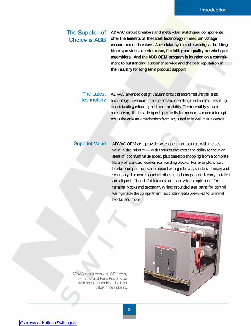
ADVAC OEM cells provide switchgear manufacturers with the bestvalue in the industry — with features that create the ability to focus onareas of optimum value added, plus one-stop shopping from a completelibrary of standard, economical building blocks. For example, circuitbreaker compartments are shipped with guide rails, shutters, primary andsecondary disconnects, and all other critical components factory-installedand aligned. Thoughtful features add more value: ample room forterminal blocks and secondary wiring; grounded steel paths for controlwiring inside the compartment; secondary leads pre-wired to terminalblocks, and more.
Superior Value
The Supplier ofChoice is ABB
The LatestTechnology
ADVAC circuit breakers and metal-clad switchgear componentsoffer the benefits of the latest technology in medium voltagevacuum circuit breakers. A modular system of switchgear buildingblocks provides superior value, flexibility and quality to switchgearassemblers. And the ABB OEM program is founded on a commit-ment to outstanding customer service and the best reputation inthe industry for long term product support.
ADVAC advanced design vacuum circuit breakers feature the latesttechnology in vacuum interrupters and operating mechanisms, resultingin outstanding reliability and maintainability. The incredibly simplemechanism, the first designed specifically for modern vacuum interrupt-ers, is the only new mechanism from any supplier in well over a decade.
ADVAC circuit breakers, OEM cells,L-Frames and Parts Kits provideswitchgear assemblers the best
value in the industry.
Courtesy of NationalSwitchgear.com

4
Introduction
Flexibility
The ADVAC breaker and switchgear components have beensubjected to rigorous ANSI design tests. Rugged, self-supporting boltedmodule construction provides consistent alignment and enables easyassembly and adjustment. Rigid hem-bending provides a total of fourlayers of steel where adjacent modules are bolted together. Modules aresuitable for use in switchgear that has been seismically certified for UBCZone 4. And each ADVAC circuit breaker is automatically tested andcycled 300 operations prior to shipment.
Quality You CanDepend On
You can count on ABB for
technology leading products –
plus the value, flexibility and
quality you need for
your business.
A wide array of primary compartment modules can be stacked in avariety of arrangements to meet virtually any application, with compactfootprints that reduce floor space and installation costs. Top or bottomentry of both primary and control wiring add versatility. The wide choiceof primary modules, coupled with ABB value-added features and quickbolt-together construction, create the flexibility to quickly order andreceive building blocks that can be efficiently configured to meet shorterlead times for complete systems. This means greater flexibility for you -and for your customers.
ADVAC circuit breakers areautomatically tested andcycled 300 operationsprior to shipment.
Courtesy of NationalSwitchgear.com

5
Product Description
PR
OD
UC
T D
ES
CR
IPTI
ON
ADVAC Circuit Breakers ................................... 6
Cell Interface and Racking ........................... 1 0
Modular Construction .................................... 1 4
Circuit Breaker Modules ............................... 1 8
Auxiliary Primary Equipment ...................... 20
Low Voltage (Instrument) Modules ............. 22
Primary Bus System ....................................... 23
Accessories ...................................................... 24
Courtesy of NationalSwitchgear.com

6
Product Description
ADVAC - Advanced Design Vacuum Circuit Breakers
The ADVAC series of vacuum circuit breakers is a complete lineof ANSI-rated circuit breakers offering power distribution systemcustomers the advantages of the latest vacuum circuit breakertechnology — technology that reduces ownership costs throughimproved reliability and maintainability.
Ratings ADVAC is available in the full range of ANSI ratings through 15 kV,with interrupting ratings to 1000 MVA and continuous currentsthrough 3000 A (self-cooled). A complete table of breaker typesand ratings is provided in the Reference Section.
OperatingMechanism
ADVAC uses a simple, front-accessible stored-energy operating mechanismdesigned specifically for use with vacuum technology. This provides thebenefits of dependable vacuum interrupters with advanced contact designand proven reliability, without the complexity of mechanisms and linkagesfound in previous generation circuit breakers.
The unique ADVAC mechanism uses a single toroidal spring (1) mountedon a drive shaft (2) to rotate the shaft in the same direction during openingand closing. The spring can be charged manually via the chain drive (3) andratchet wheel (4) , or electrically by the spring charging gear motor (notshown in this view). Three sets of precision cams (5), one for each phase,are mounted on the drive shaft. The cams operate moving stems onvacuum interrupters (8) through insulating pushrods (7) and direct-actingrocker arms (6) that convert the rotational force to linear force, acceleratingand decelerating interrupter contacts at optimum speeds during bothopening and closing operations.
The cam shape is designed for the small contact travel required by vacuuminterrupters, and when used with the toroidal spring, this provides muchmore efficient movement than the complex linkages and springs used onconventional breakers. Cam design is critical, as it determines proper contactspeed and momentum. This is an important advantage because it avoidsexcessive force that could cause premature wear on both the contacts andthe operating mechanism.
Product DescriptionADVAC
Circuit Breakers
Courtesy of NationalSwitchgear.com

7
Product Description
1
2
3
11
4
12
9
6
7
10
8
5
During closing, the shaft rotatesthe cams 270° to build momen-
tum for the proper closing forceneeded to counteract magnetic
repulsion of contacts as the breakercloses. Also during closing, upward
movement of the rocker arm charges primaryopening springs (9). These are compression type
springs at the back of the breaker, mounted between thechassis and rocker arm. Compression-type wipe springs (10)
mounted on the pushrods maintain contact pressure once the rocker armsare locked in the closed position. The cams are stopped precisely at the 270°
position by a “stop disk” (11) on the rotating shaft. The stop disk locksmain shaft rotation, cams, rocker arms, pushrods and contacts in theclosed position.
A trip signal releases a trip latch (12), which in turn allows the shaftto complete its rotation back to the full 360° position. Shaft move-ment is aided by the remaining charge on the toroidal spring.However, the principle operating force is provided by the primarycompression springs on each phase, which are now free to dis-charge because of the release of the main shaft, rocker arms andpushrod. A third, but minimal opening force is provided by thepreloaded wipe (compression) springs on the pushrods, althoughthese springs are primarily used to maintain contact pressure.
This simple concept uses only a small fraction of themoving parts found in conventional breakers, resulting inmaximum reliability over a longer life — with added savingsfrom easy, infrequent maintenance.
ADVAC Operating System
Courtesy of NationalSwitchgear.com

8
Product Description
Control System Control features of the ADVAC breaker emphasize convenience, maintain-ability and flexibility. Charge, close and trip functions can be accomplishedboth electrically and manually. All manual functions can be performed withgreat ease at the front of the breaker. Standard operator control features areshown below.
Control flexibility is the result of a wide range of standard andoptional features, including independently selectable voltagesfor electric charge, close and trip functions. Eight auxiliary switchcontacts (4 “a”, 4 “b”) are mounted on-board and wired throughthe automatic secondary disconnect. A single schematic diagram (page 48)shows all standard control features, regardless of control voltage.
Several options are available with an additional secondary discon-nect, to offer a high degree of flexibility in control system design.Options include dual isolated shunt trip coils, a direct-actingundervoltage release, and nine extra on-board contacts for a total of17 auxiliary contacts (9 “a”, 8 “b”). Since all auxiliary contacts areon-board, they operate whenever the breaker operates in eitherTest or Connected positions.
Manual springcharge port
Spring chargestatus indicator
Cell locking tabsand handles
Racking release lever
Racking padlock provision forlockout and safety procedures
Manual open andclose push buttons
Non-resettableoperations counter
Open/closed indicator
Charging motordisconnect switch
Racking access port
Front view of ADVAC circuit breaker
Courtesy of NationalSwitchgear.com

9
Product Description
ADVAC breaker with front panelremoved shows convenient accessto the simple operating mechanismand control components.
The ADVAC control system reduces ownership costs throughgreatly simplified inspection and maintenance procedures. The entireoperating mechanism and its control components are front accessible.Modular construction and the use of common components result in fewerspare parts, and the entire control package is removable for easy mainte-nance and functional changes.
Primarydisconnects
Integral wheels
Secondarydisconnect andalignment tab
Rear view of ADVAC circuit breaker
Interrupter supports
Vacuum interrupters
Flexible currenttransfer tomoving stem
Shutter actuator
Ground contact
Extensive on-board auxiliarycontacts eliminate cell-
mounted mechanismoperated (MOC) auxiliaryswitches and related me-
chanical linkages that oftenrequire adjustment on
conventional breakers.
A solid state control device replaces theconventional anti-pump relay. This improvesreliability and eliminates field adjustments.
Courtesy of NationalSwitchgear.com
10
Product Description
Cell Interfaceand Racking
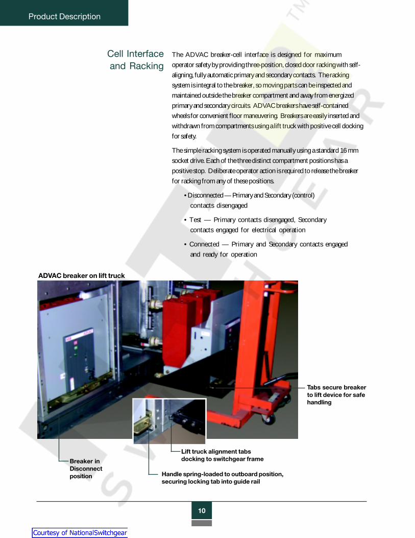
The ADVAC breaker-cell interface is designed for maximumoperator safety by providing three-position, closed door racking with self-aligning, fully automatic primary and secondary contacts. The rackingsystem is integral to the breaker, so moving parts can be inspected andmaintained outside the breaker compartment and away from energizedprimary and secondary circuits. ADVAC breakers have self-containedwheels for convenient floor maneuvering. Breakers are easily inserted andwithdrawn from compartments using a lift truck with positive cell dockingfor safety.
The simple racking system is operated manually using a standard 16 mmsocket drive. Each of the three distinct compartment positions has apositive stop. Deliberate operator action is required to release the breakerfor racking from any of these positions.
• Disconnected — Primary and Secondary (control)contacts disengaged
• Test — Primary contacts disengaged, Secondarycontacts engaged for electrical operation
• Connected — Primary and Secondary contacts engagedand ready for operation
Breaker inDisconnectposition
Tabs secure breakerto lift device for safehandling
Lift truck alignment tabsdocking to switchgear frame
Handle spring-loaded to outboard position,securing locking tab into guide rail
ADVAC breaker on lift truck
Courtesy of NationalSwitchgear.com

11
Product Description
The racking system also includes all interlocks necessary forproper sequencing and operation. An ADVAC breaker cannot beracked while contacts are closed, a breaker cannot be closed whenin an intermediate position, and an improperly rated breaker cannotbe inserted into a cell. The breaker also cannot be moved to theConnected position unless secondary contacts are engaged. Astandard padlock provision can be used to support lock-out andtag-out procedures by preventing racking in any position.
Since the racking system is fully automatic, engagement anddisconnect of both primary and secondary contacts are completelysequenced and driven by the racking operation, even with thecompartment door closed. No manual intervention is required.
Primary shutters automatically cover primary contacts when thebreaker is not in the Connected position. The shutters, which maybe of grounded metal or insulating polycarbonate material, areactuated simultaneously from both sides of the breaker for smooth,balanced operation that eliminates binding. Metallic shutters aregrounded by dedicated wiring rather than through mechanicallinkages. An interlock prevents accidental opening of the shutters.
Courtesy of NationalSwitchgear.com

12
Product Description
Dual Guide Rails
ADVAC breakers locksecurely into cells onboth sides. Dual guiderails and self-aligningprimary and secondarycontacts assure smooth,consistent racking, andsupport the breakerfirmly during peakshort circuit conditions.
Current Transformers
Each primary compartment has room for up to four standardaccuracy current transformers (CTs) per phase.
Circuit Breaker Grounding
A stationary ground bar engages thebreaker grounding contact in theDisconnected position and iscontinuous between the Disconnectedand Connected positions.
Primary Supports
Primary contacts and CTs aresupported by standard glass-polyester or optionalporcelain bushings.
Primary Shutters
Shutters automatically coverprimary contacts when thebreaker is not in theConnected position.Shutter closing is mechani-cally forced by breakerwithdrawal, rather thanrelying on springs or gravity.
InterferenceBlocking
The compartmenthas interfence blockingto prevent insertionof improperly ratedbreakers.
Courtesy of NationalSwitchgear.com

13
Product Description
Position Indicator
A position decal indicates breakerposition by alignment with thefront panel of the breaker.
TOC Actuator
Switch contacts are actuatedby the front panel as thebreaker moves in and out ofthe Connected position.
Terminal BlockMounting Space
Ample room is provided forconnections to secondary wiringfrom circuit breakers, currenttransformers and other devices.
Secondary Disconnect
A single 25-pin secondarydisconnect provides ampleconnection capacity forstandard control circuits.An optional dual disconnect(shown) accommodatesoptional control features.Female contacts reside inthe cell so that potentiallyenergized control contactsare recessed.
Courtesy of NationalSwitchgear.com
14
Product Description
ModularConstruction
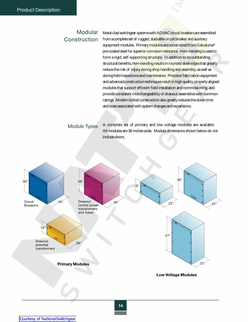
Metal-clad switchgear systems with ADVAC circuit breakers are assembledfrom a complete set of rugged, stackable circuit breaker and auxiliaryequipment modules. Primary modules are constructed from Galvalume®
pre-coated steel for superior corrosion resistance. Hem-bending is used toform a rigid, self-supporting structure. In addition to its outstandingstructural benefits, hem-bending results in rounded steel edges that greatlyreduce the risk of injury during shop handling and assembly, as well asduring field inspections and maintenance. Precision fabrication equipmentand advanced construction techniques result in high quality, properly alignedmodules that support efficient field installation and commissioning, andprovide consistent interchangeability of drawout assemblies with commonratings. Modern bolted construction also greatly reduces the down timeand costs associated with system changes and expansions.
Module Types A complete set of primary and low voltage modules are available.All modules are 36 inches wide. Module dimensions shown below do notinclude doors.
38"
39"
19"
39"
38"
39"
19"
22"
38"
22"
57"
22"Primary Modules
Low Voltage Modules
Drawoutcontrol powertransformersand fuses
Drawoutpotentialtransformers
CircuitBreakers
Courtesy of NationalSwitchgear.com

15
Product Description
FlexibleArrangements
Superior value
ADVAC circuit breakers and metal-clad components offer avariety of one-high and two-high switchgear configurationoptions as shown below. Modules are stackable to a totalheight of 95 inches.
In addition to the structural advantages of ABB modules, primarycompartments are shipped completely assembled and aligned in the factory.Pre-installed equipment includes guide rails, primary bushings and contacts,ground contact bar, and secondary disconnects pre-wired to terminal blocks.For circuit breaker modules, the automatic primary shutters are alsoinstalled, and the interference block is set for the cell current rating.
Modules also include predetermined routings for secondary wiringin grounded steel channels. Ample room for terminal blocks is providedon side panels. Grommeted “knock-outs” and convenient conduitlocations facilitate control wiring to upper and lower modules. In ABBswitchgear designs, all wiring to adjacent vertical sections is routed throughisolated low voltage modules.
TOC switches and Kirk® Key interlock mounting provisions are shipped askits for easy field installation.
1200 A - 2000 A(2000 A in bottom only)
Any breaker rating
Courtesy of NationalSwitchgear.com

16
Product Description
ModuleAssembly
Modules are enclosed by sheet steel on five sides, and are ready forimmediate assembly to adjacent units. Modules are designed to bebolted together at frequent intervals using high quality hardware,with 3/8-inch bolts penetrating four layers of steel at each point.
Primary contact
Glass-polyester primarycontact support
Grommets forcontrol wiring
Ground bus connection
Each module has bolt provisions for connection to upper or lowermodules in the same vertical section, connection to modules inadjacent vertical sections, and attachment of primary bus barriers andrear cable compartments fabricated by the switchgear assembler.
Top, side and rear provisionsfor bolting to adjacent modules
Circuit breaker module(rear view)
Courtesy of NationalSwitchgear.com

17
Product Description
Doors All modules have front flanges with hole patterns suitable for installing
bolted door hinges. Detailed information on recommended door con-
struction, ventilation, instrument mounting space, weight limits, and access
ports for breaker racking, are available for OEM reference.
Modern microprocessor technology enables
consolidation of multiple protective and
instrumentation functions for all phases into
fewer devices. Therefore, most relays and
controls can be mounted on isolated low
voltage compartment doors. In some cases,
the use of discrete relays or extensive protec-
tion systems dictate mounting instruments
on primary compartment doors. In these
situations, 10-inch front frame extensions
provide adequate depth for virtually all
door-mounted instruments. These frame
extensions match the flange hole pattern for easy bolting in place.
Extensions are available from ABB, or they can be fabricated by the
switchgear assembler using standard ABB frame extension drawings
for reference.
With appropriate low voltage compartments, the primary modules
generally stack to a total height of 95 inches in two-high breaker
configurations. Lower profile switchgear can be achieved for special
applications where a one-high breaker configuration is suitable.
Courtesy of NationalSwitchgear.com

18
Product Description
CircuitBreaker
Modules
Operational features of the ADVAC circuit breaker modules aredescribed in “Cell Interface and Racking”.
Modules rated at 1200 amps are stackable as shown in the “FlexibleArrangements” section, and upper and lower modules are similar.Upper modules require top cover plates which are available fromABB or readily fabricated by the switchgear assembler. Modulesrated at 2000 and 3000 amps have an elevated breaker rackingplatform with a venting provision at the front of the cell. Thisallows air to circulate under the breakers and eliminates the need forvented doors.
All circuit breaker modules are suitable for top or bottom entry ofcontrol wiring. Primary contacts are fabricated from solid copper.
In addition to a choice of 1200, 2000 or 3000 amp cells, importantoptions include the choice between standard glass-polyesterprimary supports and optional porcelain bushings (standard on 3000A cells), grounded metal or optional insulated polycarbonateshutters, and single or dual secondary disconnects. Other cell-mounted options include TOC switches (truck operated contacts)and Kirk Key interlock mounting provisions.
2000A Module with optional porce-lain contact supports (shuttersremoved)
Rear view of 3000A Module withstandard porcelain contact supports
Courtesy of NationalSwitchgear.com

19
Product Description
TOC Switches
Kirk KeyInterlocks
TOC switches indicate when the circuitbreaker is in the Connected position andprimary contacts are engaged. The TOCswitch consists of a mechanical switchactuated by the ADVAC breaker panel oninsertion to the Connected position, anda four-pole (2 “a”, 2 “b”), eight-pole (4“a”, 4 “b”) or twelve-pole (6 “a”, 6 “b”)electrical contact assembly driven by themechanical switch. The electricalcontacts and terminals are installed in anisolated low voltage compartmentmounted over the breaker compartment.Optional TOC switches are shipped askits for easy field installation.
Kirk interlocks are often used as safetymeasures to prevent inserting a circuitbreaker unless a specified key is present,assuring that equipment is operated in aprecise sequence. This feature istypically used to mechanically preventaccess to circuits energized by a remotesource, or to prevent the simultaneousconnection of unsynchronized sources.Optional Kirk Key interlock provisionsenable separate installation of single ordouble Kirk interlocks. Kirk mountingprovisions are shipped as kits for fieldinstallation. Kirk locks are not includedin mounting provision kits, and must beordered separately.
Courtesy of NationalSwitchgear.com

20
Product Description
Auxiliary PrimaryEquipment
PotentialTransformer (PT)
Modules
PT modules accommodate industry-leading type VIY and VIZswitchgear style potential transformers from ABB. Each moduleaccepts up to three transformers with line-to-line (L-L) or line-to-ground (L-G) connections, and is supplied with the drawout truck,PT mounting hardware, fuse clips and reusable fuse boots. PTs andfuses are supplied by the switchgear assembler. The modulesinclude recessed primary “snuffer” arc-quenching contacts, dualguide rails, and a racking system that uses the same accessories asthe circuit breaker modules. The snuffer contacts interrupt magne-tizing currents and are recessed to prevent incidental contact withenergized circuits. Secondary contacts are automatically sequencedand interlocked. PTs are automatically grounded on withdrawal todischarge residual current.
Removable,reuseable fuseboots
Primary contacts
Compartmentlocking tab
Integral wheels Drawout truck and racking system
Secondary disconnect
PT drawout assembly with three transformers
Courtesy of NationalSwitchgear.com

21
Product Description
Fuse modules accommodate up to three primary fuses for usewith fixed-mount control power transformers and other primaryvoltage level circuit protection. Fuse modules are suppliedwith drawout trucks and equipped with primary contacts, fusemountings, and fuse clips for current limiting fuses.
Drawout FuseModules
Rackingreleasehandles
Rackingaccess port
Auxiliary equipment drawer in Disconnected position
Control PowerTransformer
(CPT) Modules
CPT modules provide convenient mounting and operation of
single phase control power transformers in ratings to 15 kVA.
The modules include primary and secondary disconnects, dual guide
rails, and a racking system that uses the same accessories as circuit
breaker modules. Secondary contacts are sequenced and inter-
locked. ABB drawings indicate CPT manufacturer compatibility,
and drawout trucks with appropriate CPT and fuse mounting
hardware are included with the modules.
Note: ABB Auxiliary equipment modules do not includetransformers or fuses. These components are normallysupplied by the switchgear assembler.
Courtesy of NationalSwitchgear.com
22
Product Description
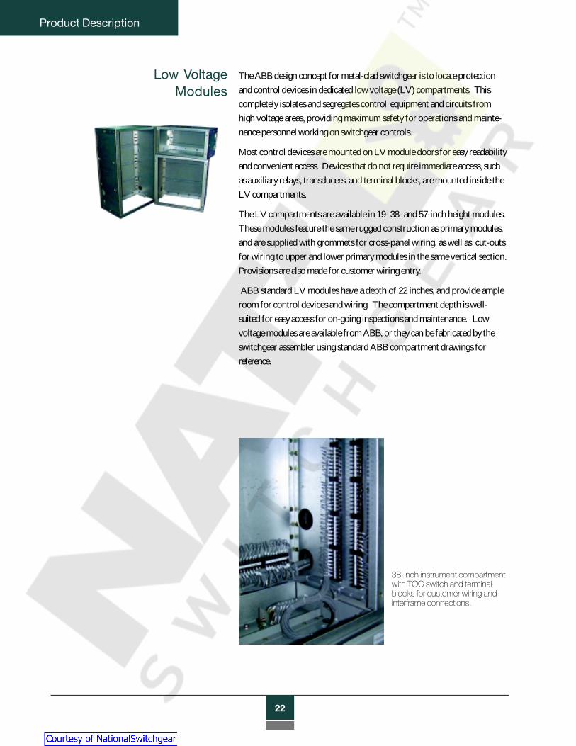
Low VoltageModules
The ABB design concept for metal-clad switchgear is to locate protectionand control devices in dedicated low voltage (LV) compartments. Thiscompletely isolates and segregates control equipment and circuits fromhigh voltage areas, providing maximum safety for operations and mainte-nance personnel working on switchgear controls.
Most control devices are mounted on LV module doors for easy readabilityand convenient access. Devices that do not require immediate access, suchas auxiliary relays, transducers, and terminal blocks, are mounted inside theLV compartments.
The LV compartments are available in 19- 38- and 57-inch height modules.These modules feature the same rugged construction as primary modules,and are supplied with grommets for cross-panel wiring, as well as cut-outsfor wiring to upper and lower primary modules in the same vertical section.Provisions are also made for customer wiring entry.
ABB standard LV modules have a depth of 22 inches, and provide ampleroom for control devices and wiring. The compartment depth is well-suited for easy access for on-going inspections and maintenance. Lowvoltage modules are available from ABB, or they can be fabricated by theswitchgear assembler using standard ABB compartment drawings forreference.
38-inch instrument compartmentwith TOC switch and terminalblocks for customer wiring andinterframe connections.
Courtesy of NationalSwitchgear.com
23
Product Description
Primary BusSystem
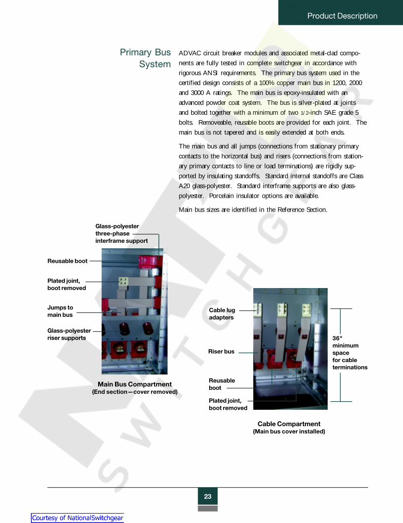
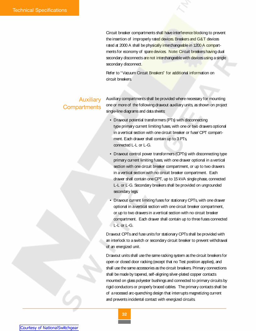
ADVAC circuit breaker modules and associated metal-clad compo-nents are fully tested in complete switchgear in accordance withrigorous ANSI requirements. The primary bus system used in thecertified design consists of a 100% copper main bus in 1200, 2000and 3000 A ratings. The main bus is epoxy-insulated with anadvanced powder coat system. The bus is silver-plated at jointsand bolted together with a minimum of two 1/2-inch SAE grade 5bolts. Removeable, reusable boots are provided for each joint. Themain bus is not tapered and is easily extended at both ends.
The main bus and all jumps (connections from stationary primarycontacts to the horizontal bus) and risers (connections from station-ary primary contacts to line or load terminations) are rigidly sup-ported by insulating standoffs. Standard internal standoffs are ClassA20 glass-polyester. Standard interframe supports are also glass-polyester. Porcelain insulator options are available.
Main bus sizes are identified in the Reference Section.
Glass-polyesterthree-phaseinterframe support
Reusable boot
Plated joint,boot removed
Glass-polyesterriser supports
Jumps tomain bus
Cable lugadapters
Riser bus
Reusableboot
Plated joint,boot removed
36"minimumspacefor cableterminations
Main Bus Compartment(End section—cover removed)
Cable Compartment(Main bus cover installed)
Courtesy of NationalSwitchgear.com

24
Product Description
Accessories The ADVAC accessory group includes a complete array ofrequired and optional special tools for proper handling, operationand maintenance of the circuit breakers and compartments.For maximum convenience, all withdrawable assemblies - circuitbreakers, PTs, CPTs, and fuses - use the same accessories.
Required accessories include a handle for manually chargingthe circuit breaker operating mechanism, and a racking crank forinserting and removing primary assemblies. A standard 16 mm socketwrench with a swivel adapter can be conveniently used for racking.
A lift truck is also required for circuit breakers and other drawoutprimary devices. The lift truck is a foot-operated hydraulic devicethat docks with the switchgear, allowing a primary device to beraised or lowered to the appropriate height and safely rolled intothe compartment. The lift truck has wheels for easy maneuveringin restricted aisle space common to switchgear installations.
Primary devices are secured to the lift truck in the same mannerused for locking the devices into switchgear compartments. The lifttruck platform is lowered to a safe position before it is used as atemporary transport device. All primary devices have self-containedwheels for easy rolling on the floor and onto the lift truck.
Courtesy of NationalSwitchgear.com

25
Product Description
An optional lifting yoke is a simplehook, chain and spreader bar assemblyused to lift circuit breakers with anoverhead crane or hoist.
A “G&T device” is a drawout assembly compatible with circuitbreaker compartments. The G&T provides a means to selectand test primary circuits in a controlled manner, and then toconnect deenergized primary circuits to the switchgear groundbus to support maintenance activity. Refer to drawing onpage 52 in the Reference Section.
The racking system of the grounded G&T device can then bepadlocked or Kirk Key interlocked in the Connected position inaccordance with lock-out and tag-out safety procedures.
Ground andTest Devices
A “test cabinet” is a wall-mounted control cabinet connected to aseparate power source and containing switches to open and close abreaker. The test cabinet has a female connector and an umbilical cord(stored inside the cabinet) for connection to the breaker, and serves as anaid to breaker inspection and maintenance in switchgear aisles or work areas.
A “test jumper” is an extension cord that allows the secondarydisconnect on a circuit breaker outside a breaker compartmentto be connected to the female connector inside the compartment.This enables the breaker to be electrically operated using controls inthe switchgear, or electrically charged after manual operation of thebreaker in a switchgear aisle.
Courtesy of NationalSwitchgear.com

26
Product Description
A “Dummy Breaker” is a no-load disconnect device similar to adrawout circuit breaker, but without an operating mechanism,controls or interrupters. It provides a three-phase short circuitcurrent path between upper and lower terminals, and usually servesto isolate entire switchgear line-ups or specific loads for mainte-nance work. Dummy devices do not have load interrupting capabil-ity, and must be Kirk Key interlocked with the switchgear powersource to prevent racking when primary circuits are energized.
DummyCircuit
Breakers
Courtesy of NationalSwitchgear.com

27
Technical Specifications
TEC
HN
ICA
L S
PE
CIF
ICAT
ION
SIntroduction ........................................................ 28
General Description ............................................ 29
Applicable Standards .......................................... 29
Ratings ................................................................ 30
Materials and Construction ................................ 30
Circuit Breaker Compartments .......................... 31
Auxiliary Compartments .................................... 32
Bus and Cable Compartments ............................ 33
Vacuum Circuit Breakers .................................... 34
Protection and Control ........................................ 37
Accessories .......................................................... 39
Documentation ................................................... 40
Testing and Verification ...................................... 40
Courtesy of NationalSwitchgear.com

28
Technical Specifications
Technical Specifications
Introduction
This section describes the basic design and functional requirements forvacuum circuit breakers and indoor (NEMA 1) metal-clad switchgearcomponents. It is provided as a guide to assist in the specification ofswitchgear, circuit breakers and related components to assure superiorsafety, reliability and maintainability in the final switchgear product.Features and provisions identified as optional should be selected asappropriate for the application. This guide does not provide compre-hensive recommendations for overall switchgear design, protective relay-ing, coordination or instrumentation. This guide also does not addressrequirements for outdoor applications.
Tables are located in the Reference Section.
This document is available in electronic format for word processing use from theABB web-site (http://www.abb.com/usa/t&d) or from an ABB OEM fieldsales representative. For additional information, contact a sales representative orthe ABB North America Distribution Switchgear Group at 1-800-338-1585.
This specification covers the general requirements for mediumvoltage metal-clad switchgear. Specific application requirements areidentified on project data sheets and single-line diagram(s). In general,when resolving conflicting information, the following order of prece-dence shall apply:
1. Single-line diagrams
2. Data sheets
3. This specification
4. Purchase order
5. Other referenced specifications
ADVAC - Advanced Design Vacuum Circuit Breakers
Courtesy of NationalSwitchgear.com

29
Technical Specifications
GeneralDescription
The metal-clad switchgear shall be of free standing, self-supportingmodular construction in one-high and two-high arrangements. Thestandard indoor frame size shall consist of 36-inch wide sections withmodules stacked to a height of 95 inches (maximum). A dress panelshall be provided on each end of a lineup. The lineup may be extendedon either end (unless coupled to other equipment) by removal of theend dress panels and the main bus covers.
The switchgear shall be provided with ABB ADVAC vacuum typedrawout circuit breakers or approved equal. The switchgear shall in-clude circuit breaker and auxiliary compartments, drawout breakers andauxiliary assemblies, the primary bus system, ground bus system, protec-tion and control devices, and connection provisions for primary, groundand control circuits, all functionally equivalent to project single-linediagrams and data sheets except as noted.
ApplicableStandards
The switchgear and circuit breakers shall be designed, tested and manu-factured in accordance with ANSI requirements for metal-cladswitchgear and the following applicable documents and industry stan-dards:
ANSI/IEEE C37.04 Standard Rating Structure for AC HV CircuitBreakers
C37.06 Preferred Ratings for AC HV Circuit BreakersC37.09 Standard Test Procedure for AC HV Circuit
BreakersC37.010 Application Guideline for AC HV Circuit
BreakersC37.011 Application Guide for TRV for AC HV Circuit
BreakersC37.012 Application Guide for Capacitance SwitchingC37.11 Requirements for Electrical ControlC37.20.2 Standard for Metal-clad and Station-Type
Cubicle SwitchgearC37.55 Conformance Testing Procedure for Metal-clad
SwitchgearC57.13 Requirements for Instrument Transformers
NEC National Electric Code, 1996 EditionNEMA CC-1 Electrical Power Connections
SG-4 Standards for Power Circuit BreakersSG-5 Power Switchgear Assemblies for NEC/NFPA
250 Enclosures for Electrical Equipment
Courtesy of NationalSwitchgear.com

30
Technical Specifications
Ratings The switchgear shall be rated at (4.76, 8.25, 15) kV maximumcontinuous voltage, (250, 350, 500, 750, 1000) MVA nominal interruptingcapacity, and (1200, 2000, 3000) amps continuous current, as shown inthe “Rating Structure” table (page 40), with required and related capabili-ties in accordance with referenced ANSI standards. Individual circuitbreaker continuous current ratings shall be as shown on the projectsingle-line diagram and data sheets.
Ratings are applicable to “General Purpose” circuit breakers as definedby ANSI, except where specific “Definite Purpose” breakers and ratingsare noted in this specification or on project data sheets.
Switchgear will be designed for usual service conditions as defined inANSI C37.20.2, and de-rating factors for unusual service conditions shallapply in accordance with this standard.
Materials andConstruction
Circuit breaker and auxiliary compartments shall be of modular con-struction and fabricated primarily from 14-gauge pre-coated Galvalumematerial (zinc-aluminum over cold-rolled carbon steel). Galvalume shallnot require painting due to superior corrosion resistance. Those compo-nents, doors and panels which require welding, or which require greaterthan 14-gauge material (and not accomplished by double walls of 14-gauge material), shall be of carbon steel that has been phosphate treatedand painted with ANSI 61 (gray) baked-on corrosion resistant epoxyenamel.
Hem-bends (rigid overlap bending) shall be consistently used to enhancestrength and to minimize potential exposures to sharp steel edges duringinstallation and maintenance.
Exterior doors and panels shall be securely hinged and fastened, andshall be capable of handling the weight of door-mounted componentswithout deformation or sagging.
Door stops shall be provided to hold doors in the full open position.
Primary compartment doors shall be provided with windows of polycar-bonate material to allow viewing of primary device position and indica-tors mounted on the front of circuit breakers.
Provisions shall be made for the addition of Kirk Key Interlocks as
indicated on project single-line diagrams and data sheets.
Options:
Courtesy of NationalSwitchgear.com

31
Technical Specifications
Circuit BreakerCompartments
Circuit breaker compartments shall be rated as shown on the project single-line diagram and data sheets, and shall include support bushings with sta-tionary primary contacts for engagement with circuit breakers or groundand test (G&T) devices. Standard bushings shall be glass-reinforced polyes-ter in 1200 A and 2000 A compartments, and porcelain bushings in 3000 Acompartments. The bushings shall be capable of supporting the weight ofspecified current transformers. Primary contacts shall be made of copperand designed to accept round, tulip-style connectors.
The 1200 A and 2000 A circuit breaker compartment bushings shallbe porcelain.
Low voltage, ring-core type current transformers (CTs) shall bebushing-mounted, located behind the shutters and accessible from the front.Bushing design shall accommodate up to four standard accuracy CTs perphase for all ratings.
Solidly grounded metal shutters shall operate automatically by withdrawingor inserting the circuit breaker or G&T device. The shutters shall blockaccess to primary contacts when the breaker is in the Test or Disconnectedpositions or withdrawn from the compartment. Shutter grounding shall beby dedicated ground wires, and shall not depend on grounding throughhinges or moving contact surfaces. Shutters shall be driven from both sidessimultaneously for smooth, balanced operation. Shutter closing shall beautomatically driven by the breaker, and shall not depend on gravity orspring return systems. Shutters shall be lockable in the closed position(padlocks supplied by others).
The shutters shall be made of non-metallic polycarbonate material.
A stationary ground contact shall be provided to interact with the groundcontact of the circuit breaker. The ground connection shall be made priorto making of the primary or secondary contacts, and shall be continuousfrom Disconnected through Connected positions. Additionally, circuitbreakers shall be grounded through the chassis and racking system in allpositions.
A single (25-pin) fully automatic self-aligning secondary disconnect shall beprovided as standard. The female portion of the disconnect system shallreside in the breaker compartment, so that energized contacts are recessedand remain “touch safe.”
A double (50-pin) disconnect arrangement shall be provided for compatibil-ity with appropriately equipped circuit breakers, as shown on projectdata sheets.
Option:
Option:
Option:
Courtesy of NationalSwitchgear.com
32
Technical Specifications
AuxiliaryCompartments
Circuit breaker compartments shall have interference blocking to preventthe insertion of improperly rated devices. Breakers and G&T devicesrated at 2000 A shall be physically interchangeable in 1200 A compart-ments for economy of spare devices. Note: Circuit breakers having dualsecondary disconnects are not interchangeable with devices using a singlesecondary disconnect.
Refer to “Vacuum Circuit Breakers” for additional information oncircuit breakers.
Auxiliary compartments shall be provided where necessary for mountingone or more of the following drawout auxiliary units, as shown on projectsingle-line diagrams and data sheets:
• Drawout potential transformers (PTs) with disconnectingtype primary current limiting fuses, with one or two drawers optionalin a vertical section with one circuit breaker or fuse/CPT compart-ment. Each drawer shall contain up to 3 PTs,connected L-L or L-G.
• Drawout control power transformers (CPTs) with disconnecting typeprimary current limiting fuses, with one drawer optional in a verticalsection with one circuit breaker compartment, or up to two drawersin a vertical section with no circuit breaker compartment. Eachdrawer shall contain one CPT, up to 15 kVA single phase, connectedL-L or L-G. Secondary breakers shall be provided on ungroundedsecondary legs.
• Drawout current limiting fuses for stationary CPTs, with one draweroptional in a vertical section with one circuit breaker compartment,or up to two drawers in a vertical section with no circuit breakercompartment. Each drawer shall contain up to three fuses connectedL-L or L-G.
Drawout CPTs and fuse units for stationary CPTs shall be provided withan interlock to a switch or secondary circuit breaker to prevent withdrawalof an energized unit.
Drawout units shall use the same racking system as the circuit breakers foropen or closed door racking (except that no Test position applies), andshall use the same accessories as the circuit breakers. Primary connectionsshall be made by tapered, self-aligning silver-plated copper contactsmounted on glass polyester bushings and connected to primary circuits byrigid conductors or properly braced cables. The primary contacts shall beof a recessed arc-quenching design that interrupts magnetizing currentand prevents incidental contact with energized circuits.
Courtesy of NationalSwitchgear.com

33
Technical Specifications
Secondary PT and CPT connections shall also be self-aligning coppercontacts. Primary and secondary connections shall be fully automaticduring insertion and withdrawal of the auxiliary unit.
Porcelain bushings shall be supplied as supports for stationaryprimary contacts in auxiliary compartments.
Drawout auxiliary trucks shall be grounded at all times. Transformerwindings or primary fuses shall be grounded when withdrawn to dis-charge residual current.
Option:
Bus and CableCompartments
The primary bus system shall be made of 100% copper with full roundedges, and shall have self-cooled ratings as specified on the projectsingle-line diagram or data sheets. Bus bar connections shall be silver-plated and mechanically secured with reusable hardware that will main-tain adequate pressures with the operating temperature range of theswitchgear.
Conductors shall be epoxy insulated, except at bolted joints. Joints shallbe covered with removable, reusable boots to facilitate field inspectionand maintenance.
The main (horizontal) bus compartment shall be separated from theother compartments by an 11-gauge steel barrier (or equivalent) and shallfully enclose the main bus. The main bus compartment shall be acces-sible from the rear through the cable compartment. Main bus ratingsshall match the highest rated circuit breaker continuous current ratings(unless a higher rating is specified on the project single-line diagram ordata sheets) and shall comply with ANSI temperature rise requirements.The main bus shall not be tapered.
Bus supports and insulation materials shall be flame-retardant, trackresistant, and non-hygroscopic. Supports for 1200 A and 2000 A unitsshall be glass-reinforced polyester. Supports for 3000 A bus shall beporcelain.
Bus supports for 1200 A and 2000 A shall be porcelain.
A termination bus shall be provided from the circuit breaker primarydisconnects to a location to allow cable connections to other equipment.Bus connections to cables and bus duct shall be rigid. Termination busarrangements shall allow at least 36 inches for primary cable terminationsand stress cones. Connections to roof entrance bushings shall be of theflexible type. Standard termination bus shall meet the bolt hole require-ments of NEMA CC-1-4.05, and will typically be the NEMA four-holepattern.
Option:
Option:
Courtesy of NationalSwitchgear.com

34
Technical Specifications
Crimp or compression type cable lugs will be provided for each switchgearsection as shown on project data sheets.
The design shall be adaptable for top or bottom primary entrance arrangements.In two-high arrangements, each set of primary connections and zero-sequencecurrent transformers, if applicable, shall be isolated into separate compartmentsby a grounded steel partition in accordance with ANSI standards. Easily remov-able primary and secondary cable entry plates of carbon steel shall be provided.
Cable entry plates shall be of non-magnetic material.
The cable compartment shall have mounting provisions for surge arresters,ground sensors and cable supports as shown on project data sheets.
A 1/4 x 2 inch solid copper ground bus, to which the entire metallic enclosure issolidly connected, shall extend through the length of the switchgear. The groundbus shall be accessible in the cable compartment, and shall have connectionprovisions for each switchgear section.
Vacuum CircuitBreakers
General The circuit breaker shall be an ABB ADVAC or approved equal three-pole drawout type breaker, electrically operated, with manual or electricmotor charging of a spring type stored energy operating mechanism. Thebreaker is intended for use as a General Purpose device in accordancewith applicable ANSI standards.
Definite purpose or non-standard ratings are required in accordance withproject data sheets, and availability is confirmed in writing with thevendor.
Circuit breakers of the same type, rating and control features shall beelectrically and mechanically interchangeable.
Racking Systemand Interlocks
The circuit breaker shall be inserted and withdrawn by means of a rack-ing system, which can be operated with the compartment door open orclosed. The racking system shall provide smooth, consistent racking, andshall secure the breaker from both sides of the cell in all racking posi-tions. During racking, the breaker shall automatically open and close cell-mounted safety shutters to cover stationary primary contacts when thebreaker is not in the Connected position.
Option:
Option:
Options:
Courtesy of NationalSwitchgear.com

35
Technical Specifications
Controls Opening and closing speed shall be independent of the operatoror of control voltage within the rated control voltage range. Circuitbreaker charge, close and trip circuits shall be electrically separate, andcontrol voltages for each circuit shall be independently selectable fromthe full range of ANSI preferred control voltages. Manual provisionsshall be provided for closing, tripping and charging the breaker. Theseprovisions shall be installed and easily accessible at the front of thebreaker.
A self-aligning, fully automatic secondary coupling system shallbe used to connect and disconnect all control wiring during circuitbreaker insertion and withdrawal. The secondary disconnect shall requireno manual intervention to attain proper position when the breaker isracked to the Connected, Test or Disconnected positions. Secondarycontacts shall use a tin-lead contact finish.
The breaker shall include eight on-board auxiliary contacts (4 “a”, 4 “b”)for customer use, wired through the secondary disconnect. All breaker-mounted contacts shall operate in both Connected andTest positions.
Nine additional contacts (5 “a”, 4 “b”) shall be installed on thebreaker and wired through the secondary disconnect, for a totalof 17 on-board contacts.
The racking system shall have three distinct positions, in additionto the withdrawn position (free movement): Disconnected (both primaryand secondary contacts disengaged), Test (primary contacts disconnectedand shutter closed, but control contacts engaged), and Connected (pri-mary and secondary contacts engaged). Positive stops shall be providedfor all three positions, with deliberate operator intervention required toenable continued insertion or withdrawal of the breaker from any posi-tion.
The racking system and all moving parts of the breaker-cell interface,including the secondary coupler, shutter actuator and ground contact,shall be capable of 250 complete rack-in/rack-out operations withoutmaintenance.
It shall not be possible to insert or withdraw a closed breaker, and thebreaker shall not be allowed to close within a cell unless it is in a positiveConnected, Test, or Disconnected position. The springs in the stored-energy operating mechanism shall be automatically discharged prior toremoving a circuit breaker from a compartment. (other than spring pre-load charges which do not have the capacity to operate the circuitbreaker).
Option:
Courtesy of NationalSwitchgear.com
36
Technical Specifications
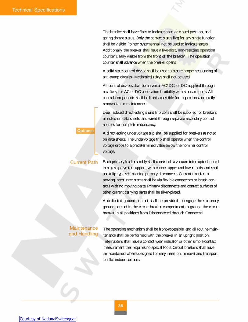
The breaker shall have flags to indicate open or closed position, andspring charge status. Only the correct status flag for any single functionshall be visible. Pointer systems shall not be used to indicate status.Additionally, the breaker shall have a five-digit, non-resetting operationcounter clearly visible from the front of the breaker. The operationcounter shall advance when the breaker opens.
A solid state control device shall be used to assure proper sequencing ofanti-pump circuits. Mechanical relays shall not be used.
All control devices shall be universal AC/DC, or DC supplied throughrectifiers, for AC or DC application flexibility with standard parts. Allcontrol components shall be front-accessible for inspections and easilyremovable for maintenance.
Dual isolated direct-acting shunt trip coils shall be supplied for breakersas noted on data sheets, and wired through separate secondary controlsources for complete redundancy.
A direct-acting undervoltage trip shall be supplied for breakers as notedon data sheets. The undervoltage trip shall operate when the controlvoltage drops to a predetermined value below the nominal controlvoltage.
Current Path Each primary lead assembly shall consist of a vacuum interrupter housedin a glass-polyester support, with copper upper and lower leads, and shalluse tulip-type self-aligning primary disconnects. Current transfer tomoving interrupter stems shall be via flexible connectors or brush con-tacts with no moving parts. Primary disconnects and contact surfaces ofother current carrying parts shall be silver-plated.
A dedicated ground contact shall be provided to engage the stationaryground contact in the circuit breaker compartment to ground the circuitbreaker in all positions from Disconnected through Connected.
Maintenanceand Handling
The operating mechanism shall be front-accessible, and all routine main-tenance shall be performed with the breaker in an upright position.Interrupters shall have a contact wear indicator or other simple contactmeasurement that requires no special tools. Circuit breakers shall haveself-contained wheels designed for easy insertion, removal and transporton flat indoor surfaces.
Options:
Courtesy of NationalSwitchgear.com

37
Technical Specifications
Protectionand Control
Relays andInstruments
Relays and instruments shall be provided and wired as specified on theproject single-line diagram and data sheets. Multi-function, three-phasemicroprocessor-based relay and control devices shall be used to themaximum practical extent. For maximum safety and ease of mainte-nance, the use of larger low voltage compartments and one-high con-struction shall be given precedence over stacked primary compartmentswhen alternative relay and instrument types are used. Door-mountedprotective relays shall be drawout type whenever practical.
Electromechanical meters, when used, shall be the flush-mount 1%accuracy taut-band switchboard type, with a minimum 250% scale.
CurrentTransformers
ABB type SAB current transformers shall be supplied as shown onproject data sheets and the single-line diagram. Zero sequence transform-ers shall be ABB type BYZ-S. Ratings and accuracy class shall be inaccordance with ANSI C57.13. CT nameplates shall be located on theCT housing and information provided shall be in accordance with ANSIC57.13. CT windings shall terminate on screw type terminals on the CThousings and shall be wired to shorting terminal blocks.
ABB type VIY and VIZ potential transformers shall be supplied inaccordance with project data sheets and the single-line diagram. Poten-tial transformer ratings and accuracy class shall be in accordance withANSI C57.13 and designed to withstand the Basic Impulse Level (BIL)of the switchgear. Potential transformers shall always be fused. Potentialtransformers shall be mounted as draw-out devices in auxiliary compart-ments.
PotentialTransformers
Circuit breaker auxiliary contacts shall be used instead of cell-mountedmechanism operated contacts (MOC switches) for each breaker so notedon project data sheets. The auxiliary contacts shall be wired through theautomatic secondary disconnect system. Refer to “Vacuum CircuitBreakers” for additional requirements.
A four contact (2 “a”, 2 “b”), eight-contact (4 “a”, 4 “b”) or twelve-contact (6 “a”, 6 “b”) truck operated contact (TOC) actuator and switchassembly shall be provided to indicate when the breaker is in the fullyConnected position, for each breaker so noted on project data sheets.
Spare contacts shall be wired to terminal blocks for easy access andfuture use.
AuxiliarySwitches
Option:
Courtesy of NationalSwitchgear.com
38
Technical Specifications
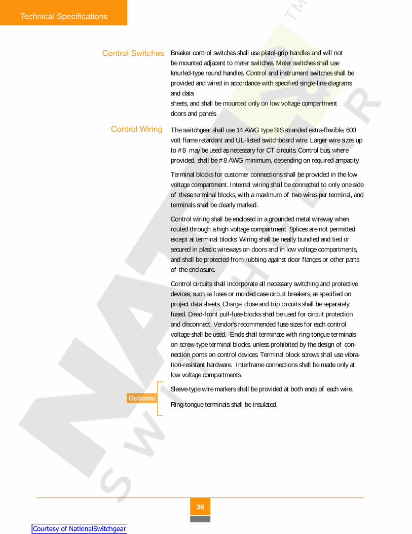
Control Switches Breaker control switches shall use pistol-grip handles and will notbe mounted adjacent to meter switches. Meter switches shall useknurled-type round handles. Control and instrument switches shall beprovided and wired in accordance with specified single-line diagramsand datasheets, and shall be mounted only on low voltage compartmentdoors and panels.
The switchgear shall use 14 AWG type SIS stranded extra-flexible, 600volt flame retardant and UL-listed switchboard wire. Larger wire sizes upto #8 may be used as necessary for CT circuits. Control bus, whereprovided, shall be #8 AWG minimum, depending on required ampacity.
Terminal blocks for customer connections shall be provided in the lowvoltage compartment. Internal wiring shall be connected to only one sideof these terminal blocks, with a maximum of two wires per terminal, andterminals shall be clearly marked.
Control wiring shall be enclosed in a grounded metal wireway whenrouted through a high voltage compartment. Splices are not permitted,except at terminal blocks. Wiring shall be neatly bundled and tied orsecured in plastic wireways on doors and in low voltage compartments,and shall be protected from rubbing against door flanges or other partsof the enclosure.
Control circuits shall incorporate all necessary switching and protectivedevices, such as fuses or molded case circuit breakers, as specified onproject data sheets. Charge, close and trip circuits shall be separatelyfused. Dead-front pull-fuse blocks shall be used for circuit protectionand disconnect. Vendor’s recommended fuse sizes for each controlvoltage shall be used. Ends shall terminate with ring-tongue terminalson screw-type terminal blocks, unless prohibited by the design of con-nection ponts on control devices. Terminal block screws shall use vibra-tion-resistant hardware. Interframe connections shall be made only atlow voltage compartments.
Sleeve-type wire markers shall be provided at both ends of each wire.
Ring-tongue terminals shall be insulated.
Control Wiring
Options:
Courtesy of NationalSwitchgear.com
39
Technical Specifications
Space heaters shall be provided at appropriate locations in each verticalsection. Heaters shall be protected to prevent accidental contact byoperating personnel.
Space heaters shall be separately fused for each vertical section orbreaker, as applicable. Space heaters shall be energized whenever circuitbreakers are open or controlled by an automatic thermostat located ineach vertical section or lineup, as shown on project data sheets. Optionalheater controls shall include disconnect switches, bypass switches, amme-ters and thermostats.
Note: Space heaters shall be standard on outdoor equipment.
Space Heaters
The following accessories shall be provided for each lineup or in quanti-ties as noted on project data sheets:
• Hand crank (16 mm socket drive) for manually operatingracking system for the circuit breaker, PT, CPT, or draw-outfuse (required)
• Handle for manually charging the stored energy system on circuitbreakers (required)
• Transport and lifting device to allow a circuit breaker, orauxiliary drawout unit, to be elevated and then inserted or withdrawnfrom upper or lower compartments (required)
• Electrical test jumper for connecting the breaker to the switchgearcontrol circuit while the breaker is completely outof the cell
• Electrical test cabinet with door-mounted open and closepushbuttons for testing the circuit breaker away from the switchgear
• Ground & Test device – three-terminal or six-terminal, manuallyoperated standard device
• Lifting yoke or similar breaker accessory for overhead lifting ofcircuit breakers
Accessories
Options:
Options:
Courtesy of NationalSwitchgear.com

40
Technical Specifications
Design tests, to verify ANSI ratings as identified in this specification,shall be documented as required by ISO 9001 and available for reviewand inspection.
Testing andVerification
Standard approval drawings shall consist of a system single-line drawing;general arrangement; front view; floor plan; nameplate drawing; and billof materials. Final drawings shall consist of as-built approval drawingsplus three-phase elementary, schematic, and interconnection wiringdiagrams.
Drawings shall indicate all equipment, but only such equipment,as is actually in the switchgear scope of supply. All user connection andinterface points shall be clearly marked, including primary and secondarycable entrances and connection points; installation details; and inter-frame assembly and connection details for shipping splits.
Drawings shall be professionally prepared on computer aided draftingsystems to the maximum extent practical, and shall be provided to thecustomer by electromagnetic disk or on reproducible and paper copies inquantities as shown on project data sheets.
An instruction manual shall be provided with necessary information forreceiving, handling, storage, installation, operation and maintenance. Theinstruction manual shall assist in identification and ordering of recom-mended spare parts.
Documentation
Courtesy of NationalSwitchgear.com
Reference
41
RE
FER
EN
CE
Rating Structure .............................................. 4 2
Capacitance Switching Ratings .................... 4 3
Altitude Rating Correction Factors ............. 4 3
Mechanical Endurance .................................. 4 4
Noise Level ........................................................ 4 4
Auxiliary and TOC Switches ........................ 4 5
Close and Trip Coils ....................................... 4 6
Charging Motor ............................................... 4 7
Timing Characteristics .................................. 4 8
Vacuum Interrupters ..................................... 4 8
Bus Support Materials ................................... 4 9
Main Bus Sizes ................................................. 4 9
Circuit Breaker Schematic Diagram ........... 5 0
Circuit Breaker Outline ................................. 5 1
Ground and Test Device Outline ................... 5 2
Courtesy of NationalSwitchgear.com

42
Reference
RatingStructure
The following table identifies standard ADVAC circuit breakertypes and ratings, and provides the most commonly requiredratings and related capabilities for metal-clad switchgear.ADVAC circuit breakers are suitable for “General Purpose”applications as defined by applicable ANSI standards (refer toTechnical Specification). Contact the factory for availability ofnon-standard or “Definite Purpose” ratings.
ReferenceADVAC - Advanced Design Vacuum Circuit Breakers
Rated Rated Short CapabilityVoltage Impulse Circuit Current
Nominal kV Low Freq. Level kA Sym Short Close RatedVoltage Nominal Withstand (BIL) Time and Voltage
Breaker Class MVA Min. Max. Voltage kV @ Min. @ Max. kA rms Latch RangeType kV Class rms rms kV rms Crest kV kV 2 Sec. kA Peak Factor
5ADV36 4.16 250 3.8 4.76 19 60 36 29 36 97 1.24
5ADV49 4.16 350 4 4.76 19 60 49 41 49 132 1.19
7.5ADV41 7.2 500 6.6 8.25 36 95 41 33 41 111 1.25
15ADV23 13.8 500 11.5 15 36 95 23 18 23 62 1.3
15ADV36 13.8 750 11.5 15 36 95 36 28 36 97 1.3
15ADV48 13.8 1000 11.5 15 36 95 48 37 48 130 1.3
NOTES:
1. Each circuit breaker is available in continuous current ratings of 1200, 2000 or 3000 A rms.
2. Interrupting time is rated at 5 cycles (0 — 100%).
3. The asymmetric capability ratio rating is 1.2.
4. Ratings are 50/60 Hz basis.
Courtesy of NationalSwitchgear.com

Reference
43
CapacitanceSwitching
Ratings
Capacitance switching ratings are as specified in the table belowand are subject to the following conditions.
1. The transient voltage from line-to-ground shall not exceedthree times the maximum design line to ground crestvoltage as measured at the circuit breaker terminals.
2. The number of re-strikes or re-ignitions shall not be limitedas long as the transient voltage to ground does not exceedthe value given in number 1 above.
3. The capacitor rating applies only to “Single BankSwitching”.
Interrupting time is in accordance with the rated interrupting timeof the circuit breaker.
AltitudeRating
CorrectionFactors
ADVAC Breaker Continuous Current Rating
1200 A 2000 A
Rated Maximum Rated Short Circuit General Definite General DefiniteVoltage (kV RMS) Current (kA RMS) Purpose Purpose Purpose Purpose
04.76 29 400 630 400 1000
04.76 41 400 630 400 0630
08.25 33 250 630 250 1000
15.00 18 250 630 250 1000
15.00 28 250 630 250 1000
15.00 37 250 630 250 0630Contact factory for availability of capacitance switching information on 3000 A circuit breakers.
Rating Correction Factor*
Continuous Voltage & DielectricAltitude (ft.) Current Withstand
03,300 (and below) 1.00 1.00
05,000 0.99 0.95
10,000 0.95 0.80*Values for intermediate altitudes may be derived from linear interpolation.
This table must be used in accordance with ANSI C37.04 tocorrect published circuit breaker ratings for operation at altitudesover 3,300 feet above sea level.
Courtesy of NationalSwitchgear.com
44
Reference
MechanicalEndurance
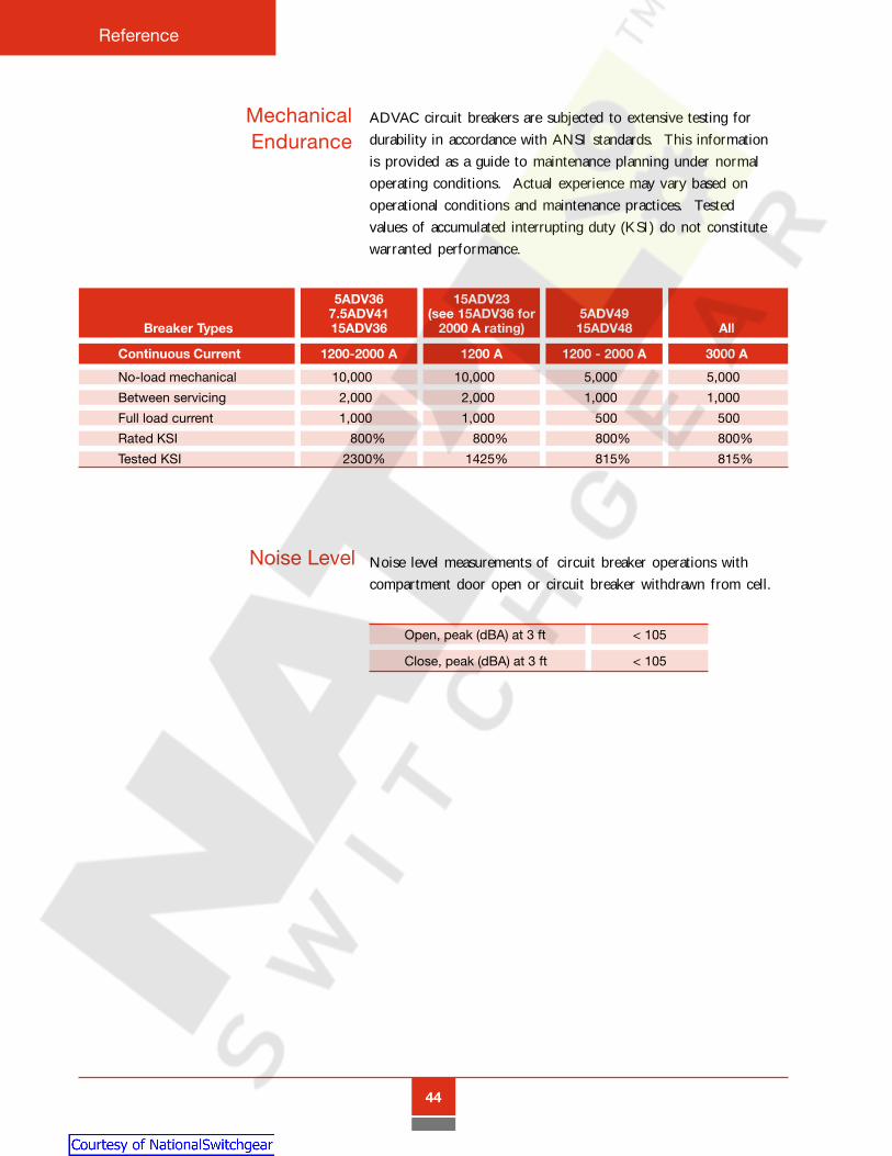
ADVAC circuit breakers are subjected to extensive testing fordurability in accordance with ANSI standards. This informationis provided as a guide to maintenance planning under normaloperating conditions. Actual experience may vary based onoperational conditions and maintenance practices. Testedvalues of accumulated interrupting duty (KSI) do not constitutewarranted performance.
Noise Level
5ADV36 15ADV237.5ADV41 (see 15ADV36 for 5ADV49
Breaker Types 15ADV36 2000 A rating) 15ADV48 All
Continuous Current 1200-2000 A 1200 A 1200 - 2000 A 3000 A
No-load mechanical 10,000% 10,000% 5,000% 5,000%
Between servicing 2,000% 2,000% 1,000% 1,000%
Full load current 1,000% 1,000% 500% 500%
Rated KSI 800% 800% 800% 800%
Tested KSI 2300% 1425% 815% 815%
Open, peak (dBA) at 3 ft < 105
Close, peak (dBA) at 3 ft < 105
Noise level measurements of circuit breaker operations withcompartment door open or circuit breaker withdrawn from cell.
Courtesy of NationalSwitchgear.com

Reference
45
Circuit breaker auxiliary switches operate whenever the breakeropens or closes. Contacts are compression type, mounted onthe breaker and wired to switchgear terminal blocks through thesecondary disconnect system. Contacts are operated throughsimple mechanical links from an auxiliary drive shaft which rotatesin conjunction with the main drive shaft. Switch contacts are silver-plated.
The standard contact configuration is four “a” contacts (normallyopen when the breaker is open), and four “b” contacts (normallyclosed when the breaker is open). An optional dual secondarydisconnect enables the addition of five “a” contacts and four “b”contacts, for a total of nine “a” and eight “b” contacts. The contactsare not field reversible.
Auxiliaryand TOCSwitches
Auxiliary Contact Continuous SwitchingCurrent Ratings (A) (A)
@ 250 VDC 10 02.0
@ 125 VDC 10 04.0
@ 48 VDC 10 06.0
@ 24 VDC 10 07.7
@ 240 VAC 10 10.0
@ 120 VAC 10 10.0
Optional TOC switches are actuated bymovement of the ADVAC front panel toindicate when the breaker is in theConnected position. TOC switch contactsare mounted in an isolated low voltagearea at the top of the breaker compart-ment. TOC switches are available withfour, eight or twelve contacts, with aneven number of “a” contacts (normallyopen when breaker is not Connected) and“b” contacts (normally closed with breakeris not Connected). Contacts are notfield-reversible.
TOC Switch Continuous SwitchingCurrent Ratings (A) (A)
@ 250 VDC 20 05.0
@ 125 VDC 20 10.0
@ 48 VDC 20 12.0
@ 24 VDC 20 15.0
@ 240 VAC 20 10.0
@ 120 VAC 20 15.0
Auxiliary contacts operate whenever thebreaker is operated, regardless of breakerposition in the compartment. If controlcircuits require differentiation betweenconnected and disconnected positions, it isnecessary to wire an optional truckoperated contact (TOC) into theappropriate auxiliary switch circuit(s).
Courtesy of NationalSwitchgear.com
46
Reference
Close andTrip Coils
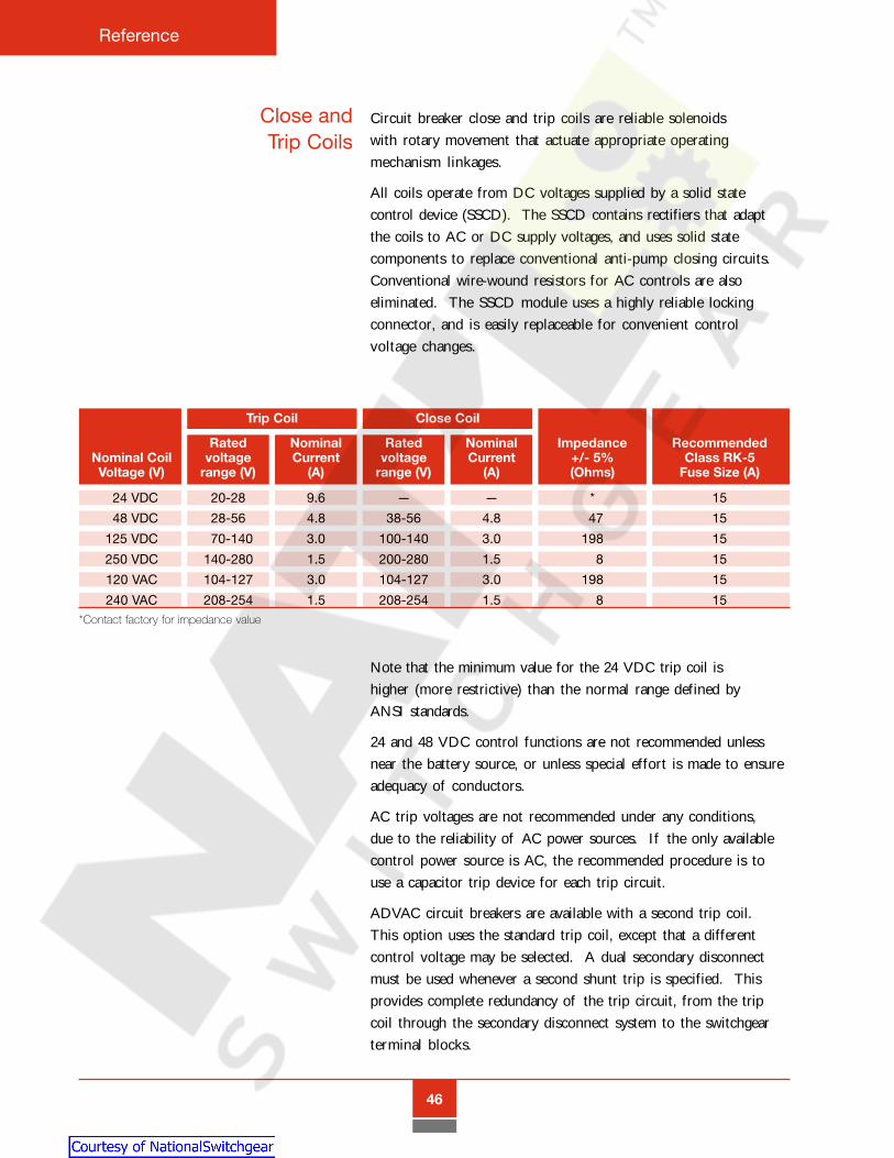
Circuit breaker close and trip coils are reliable solenoidswith rotary movement that actuate appropriate operatingmechanism linkages.
All coils operate from DC voltages supplied by a solid statecontrol device (SSCD). The SSCD contains rectifiers that adaptthe coils to AC or DC supply voltages, and uses solid statecomponents to replace conventional anti-pump closing circuits.Conventional wire-wound resistors for AC controls are alsoeliminated. The SSCD module uses a highly reliable lockingconnector, and is easily replaceable for convenient controlvoltage changes.
Note that the minimum value for the 24 VDC trip coil ishigher (more restrictive) than the normal range defined byANSI standards.
24 and 48 VDC control functions are not recommended unlessnear the battery source, or unless special effort is made to ensureadequacy of conductors.
AC trip voltages are not recommended under any conditions,due to the reliability of AC power sources. If the only availablecontrol power source is AC, the recommended procedure is touse a capacitor trip device for each trip circuit.
ADVAC circuit breakers are available with a second trip coil.This option uses the standard trip coil, except that a differentcontrol voltage may be selected. A dual secondary disconnectmust be used whenever a second shunt trip is specified. Thisprovides complete redundancy of the trip circuit, from the tripcoil through the secondary disconnect system to the switchgearterminal blocks.
Trip Coil Close Coil
Rated Nominal Rated Nominal Impedance RecommendedNominal Coil voltage Current voltage Current +/- 5% Class RK-5Voltage (V) range (V) (A) range (V) (A) (Ohms) Fuse Size (A)
024 VDC 20-28 9.6 — — * 15
048 VDC 28-56 4.8 38-56 4.8 047 15
125 VDC 070-140 3.0 100-140 3.0 198 15
250 VDC 140-280 1.5 200-280 1.5 008 15
120 VAC 104-127 3.0 104-127 3.0 198 15
240 VAC 208-254 1.5 208-254 1.5 008 15*Contact factory for impedance value
Courtesy of NationalSwitchgear.com
Reference
47
ADVAC circuit breakers are also available with an optionalundervoltage trip feature. This is a direct acting trip coil thatactuates the trip linkage when the control voltage drops below35 - 70% of the nominal range. This prevents a condition fromhappening in which control voltage is no longer available to trip abreaker. This feature is not available for 24 VDC trip circuits.
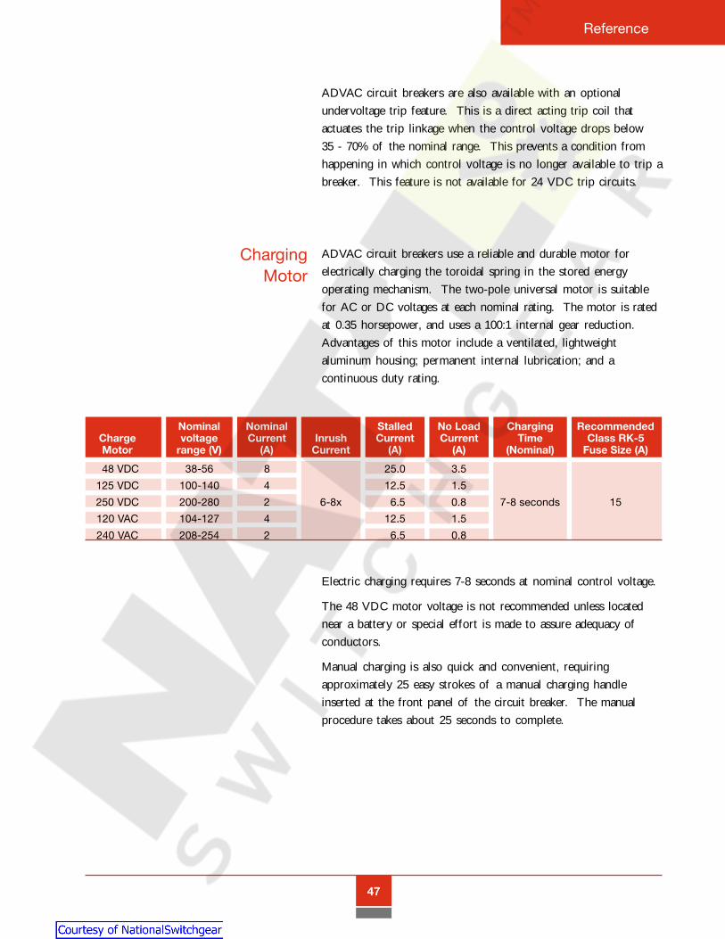
Charging Motor
ADVAC circuit breakers use a reliable and durable motor forelectrically charging the toroidal spring in the stored energyoperating mechanism. The two-pole universal motor is suitablefor AC or DC voltages at each nominal rating. The motor is ratedat 0.35 horsepower, and uses a 100:1 internal gear reduction.Advantages of this motor include a ventilated, lightweightaluminum housing; permanent internal lubrication; and acontinuous duty rating.
Electric charging requires 7-8 seconds at nominal control voltage.
The 48 VDC motor voltage is not recommended unless locatednear a battery or special effort is made to assure adequacy ofconductors.
Manual charging is also quick and convenient, requiringapproximately 25 easy strokes of a manual charging handleinserted at the front panel of the circuit breaker. The manualprocedure takes about 25 seconds to complete.
Nominal Nominal Stalled No Load Charging RecommendedCharge voltage Current Inrush Current Current Time Class RK-5Motor range (V) (A) Current (A) (A) (Nominal) Fuse Size (A)
048 VDC 38-56 8 25.0 3.5
125 VDC 100-140 4 12.5 1.5
250 VDC 200-280 2 6-8x 06.5 0.8 7-8 seconds 15
120 VAC 104-127 4 12.5 1.5
240 VAC 208-254 2 06.5 0.8
Courtesy of NationalSwitchgear.com

48
Reference
TimingCharacteristics
The ADVAC circuit breaker uses the same stored energymechanism for all ratings, resulting in consistent operationand timing characteristics in all ratings and configurations.
Vacuum Interrupters
Nominal closing time 60 ms
Nominal opening time 35-40 ms
Arcing time < 15 ms
Nominal interrupting time < 55 ms
Motor charging time 7-8 seconds *
Manual charging time ~ 25 seconds **
**at nominal control voltage**requires approximately 25 strokes of charging handle
ADVAC circuit breakers use superior quality vacuum interrupterswith proven reliability over a long life. All interrupters useadvanced copper-chrome contact material for superiorperformance and minimum current chop.
***** Overvoltages are dependent on the surge impedance of the circuit
5ADV36 15ADV237.5ADV41 (see 15ADV36 for 5ADV49
Breaker Types 15ADV36 2000 A rating) 15ADV48 All
Continuous Current 1200-2000 A 1200 A 1200 - 2000 A 3000 A
Contact shape Spiral
Contact resistance (@ rated current) <10 µΩ <18 µΩ <10 µΩ <10 µΩField design Radial
No-load mechanical life 10,000 operations 5,000 operations
Vacuum (Torr) 10-8 to 10-7
Maximum chop current* ~5 A
Moving stem current Flexible Flexible Brush Brushtransfer method
Courtesy of NationalSwitchgear.com

Reference
49
Bus SupportMaterials
ADVAC design certifications are based on glass-polyester andporcelain primary bus supports. Glass-polyester is standard forprimary contacts and bus rated at 1200 A and 2000 A, andporcelain is standard at the 3000 A rating. Porcelain supports arealso available at 1200 A and 2000 A. Separate drawings areavailable to indicate the position and dimensions of thecompartment-mounted primary contact supports, inter-framehorizontal bus supports, and Class A-20 standoff insulators.Physical characteristics of glass-polyester and porcelain areprovided in the following table.
GlassCharacteristic Polyester Porcelain
Flexural Strength, psi 15 - 27,000 10,500
Tensile Strength, psi 14,000 06,000
Izod Impact ft-lb. per inch of notch 06 - 12 1.5
Thermal Shock cycles 32° - 2300°F 100+ 1
Dielectric Strength (Short Time)vpm .125" thick, 25°C 350 - 375 300
Dielectric Constant 4 - 6 6
Main BusSizes
ADVAC design certifications are based on 100% copper bus withfull round edges and sizes as shown in the following table. Themain horizontal bus is not tapered. Connection joints are silver-plated, and at least two properly-torqued 1/2-inch SAE grade 5steel bolts are used at each joint. The bus is epoxy insulated, andremovable boots are used at joints.
Main Bus Sizes
Rating Quantity Size
05 kV, 250 MVA1200 A 15 kV, 500 MVA 1 .25" x 4"
15 kV, 750 MVA
05 kV, 350 MVA1200 A 7.5 kV, 500 MVA 1 .75" x 4"
15 kV, 1000 MVA
2000 A All 1 .75" x 4"
3000 A All 2 .75" x 4"
Courtesy of NationalSwitchgear.com
50
Reference
CircuitBreaker
SchematicDiagram
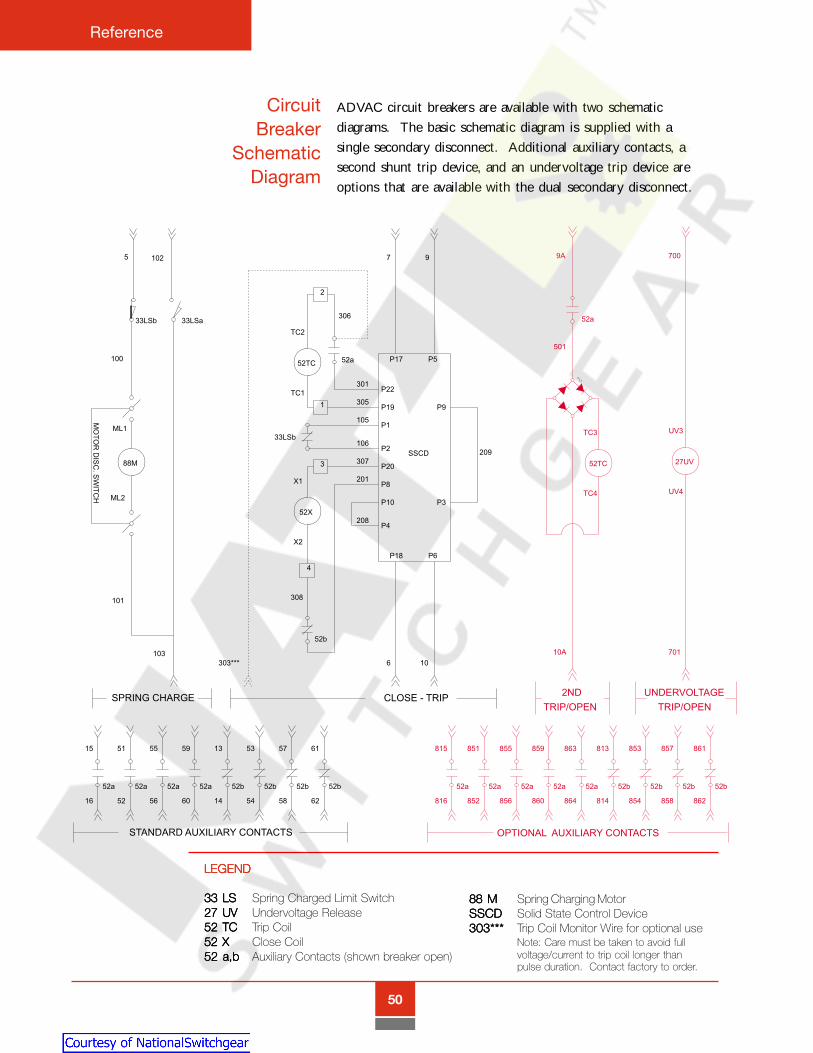
ADVAC circuit breakers are available with two schematicdiagrams. The basic schematic diagram is supplied with asingle secondary disconnect. Additional auxiliary contacts, asecond shunt trip device, and an undervoltage trip device areoptions that are available with the dual secondary disconnect.
LEGENDLEGENDLEGENDLEGENDLEGEND
33 LS33 LS33 LS33 LS33 LS Spring Charged Limit Switch27 UV27 UV27 UV27 UV27 UV Undervoltage Release52 TC52 TC52 TC52 TC52 TC Trip Coil52 X52 X52 X52 X52 X Close Coil52 a,b52 a,b52 a,b52 a,b52 a,b Auxiliary Contacts (shown breaker open)
88 M88 M88 M88 M88 M Spring Charging MotorSSCDSSCDSSCDSSCDSSCD Solid State Control Device303***303***303***303***303*** Trip Coil Monitor Wire for optional use
Note: Care must be taken to avoid fullvoltage/current to trip coil longer thanpulse duration. Contact factory to order.
Courtesy of NationalSwitchgear.com

Reference
51
CircuitBreakerOutline
Front ViewFront ViewFront ViewFront ViewFront View Side ViewSide ViewSide ViewSide ViewSide View
TTTTTop Viewop Viewop Viewop Viewop View
ADVAC circuit breaker dimensions are similar for all 36-inch widecompartments and ratings. The operating mechanism, controlcomponents, racking system and accessories are the same for allratings. Breakers with higher interrupting and continuous currentratings use various primary lead assemblies and interrupterhousings with different appearances, but cell interface dimensionsare identical. To reduce racking force requirements, some 3000 Aprimary contacts are offset slightly to the rear for sequencedcontact engagement.
Courtesy of NationalSwitchgear.com

52
Reference
Ground and TestDevice Outline
Front ViewFront ViewFront ViewFront ViewFront View Side ViewSide ViewSide ViewSide ViewSide View
TTTTTop Viewop Viewop Viewop Viewop View
NOTES:NOTES:NOTES:NOTES:NOTES:
1. The device is for use with cells designed forADVAC breakers.
2. Two (2) sets of cables are furnished. The short setattaches to the lower terminal set, and the long setattaches to the upper terminal set.
3. This device is designed for use with only one set ofcables attached to a terminal set at any given time.Either the upper terminals are grounded throughtheir cable set, or the lower terminals are groundedthrough their cable set.
4. Position stops are provided in the Connected andDisconnected positions. To assure that the deviceis in the fully Connnected position, the "Connect"label must be in the correct position.
5. Device cannot be stored in breaker compart-ments.
G&T devices are interchangeable with ADVAC circuit breakers inappropriately rated compartments. These devices provide amanual means to select and test primary circuits in a controlledmanner, and then ground a set of de-energized primary contactsto the switchgear ground bus. The racking system can be pad-locked to keep the G&T in the grounded position during mainte-nance activity. G&T devices are available with six terminals(shown below) or three terminals. Three-terminal devices can beordered with upper or lower terminals. G&T devices are notrated for switching or interrupting duty. A single device can beused for both 1200 A and 2000 A compartments, and a separateG&T is required for 3000 A compartments.
Courtesy of NationalSwitchgear.com
Reference
53
TypicalOperating
Procedure forGrounding the
Circuit
1. Disconnect the ground cables from all terminals.
2. Swing the door over the device terminal set that is notbe grounded.
3. Padlock the door in position.
4. Install the device in the switchgear compartment.
5. Close and secure the switchgear door.
6. Rack the device to the Connected position. The device mustbe in the fully Connected position. The Connected label mustbe in the appropriate position to assure that the device isinstalled properly.
7. Open the switchgear door.
8. Test the exposed terminal ends to assure that the terminal setto be grounded is not energized.
9. After establishing that the exposed terminal set is de-ener-gized, close the switchgear door, and rack the device to theDisconnected position.
10. Open the switchgear door, with the device in the Discon-nected position, and attach the upper or lower ground cablesto the exposed terminal set.
11. With the grounded cables attached, close and securethe switchgear door and rack the device to theConnected position.
12. With the ground cables installed and the device racked to theConnected position, the terminal set connected to the groundcables is grounded to the switchgear ground bus.
Courtesy of NationalSwitchgear.com


655 Century Point 2300 Mechanicsville HighwayLake Mary, FL 32746 Florence, SC 29501Tel: +1-407-723-2000 Tel: + 843-413-4800
1-800-929-7947 1-800-338-1585Fax: +1407-732-2161 Fax: +1-843-413-4850www.abb.com/mediumvoltage www.abb.com/mediumvoltage
TB3.
2.8
- 1B
Feb
ruar
y 20
02
Courtesy of NationalSwitchgear.com
Related Documents