Adsorption and electrothermal desorption of organic vapors using activated carbon adsorbents with novel morphologies Lingai Luo a, * , David Ramirez b , Mark J. Rood b,e, * , Georges Grevillot c , K. James Hay d , Deborah L. Thurston b,e a LOCIE, ESIGEC, Universite de Savoie, Campus Scientific, Savoie Technolac, 73376, Le Bourget-Du-Lac cedex, France b Department of Civil and Environmental Engineering, University of Illinois, Urbana, IL 61801-2352, USA c Laboratoire des Sciences du Genie Chimique, CNRS, ENSIC-INPL, BP451 54001, Nancy, France d U.S. Army Engineer Research and Development Center, Construction Engineering Research Laboratory, Champaign, IL 61826-9005, USA e Department of General Engineering, University of Illinois, Urbana, IL 61801-2352, USA Received 22 January 2006; accepted 3 April 2006 Available online 5 June 2006 Abstract Novel morphologies of activated carbons such as monolith, beads and fiber cloth can effectively capture organic vapors from indus- trial sources. These adsorbent materials are also unique because they can undergo direct electrothermal regeneration to recover the adsorbed organic vapors for potential re-use. This investigation compares and contrasts the properties of these adsorbents when using electrothermal–swing adsorption. The adsorption systems consisted of an organic vapor generation system, an electrothermal–swing adsorption vessel, a gas detection unit, and a data acquisition and control system. The activated carbon monolith (ACM) had the lowest pressure drop, highest permeability, highest electrical resistivity and lowest cost as compared to the activated carbon beads (ACB) and the activated carbon fiber cloth (ACFC). ACB had the largest throughput ratio and lowest length of unused bed as compared to the other adsorbents. However, ACFC had the largest adsorption capacity for toluene when compared to ACM and ACB. ACFC was also faster to regenerate and had a larger concentration factor than ACM and ACB. These results describe relevant physical, electrical, adsorption and cost properties for specific morphologies of the adsorbents to more effectively capture and recover organic vapors from gas streams. Ó 2006 Elsevier Ltd. All rights reserved. Keywords: Activated carbon; Carbon beads; Carbon cloth; Adsorption; Adsorption properties 1. Introduction Adsorption processes with activated carbons are widely used to remove organic vapors from gas streams that are generated from a wide range of industries. Methods used to regenerate carbonaceous adsorbents include steam [1,2], warm dry gas [3,4], vacuum [5], and indirect [6,7]/ direct [8] electrothermal treatments. Regeneration of these activated carbons results in gas streams that contain con- centrated single component or multi-component organic compounds. These concentrated compounds are then more readily destroyed or recovered before they are emitted to the atmosphere. Destruction of the organic vapors gener- ally occurs by incineration or biofiltration. Recovery of the organic vapors as liquids typically occurs for industrial gas streams by condensation and possibly phase separa- tion. This paper discusses the adsorption of organic vapors and direct electrothermal regeneration with activated car- bon adsorbents in the form of a monolith, beads and fiber cloth. Direct-electrothermal regeneration by the direct Joule effect uses the adsorbent as an electrical resistor to heat 0008-6223/$ - see front matter Ó 2006 Elsevier Ltd. All rights reserved. doi:10.1016/j.carbon.2006.04.007 * Corresponding authors. Tel.: +1 4 79 75 81 93; fax: +1 4 79 75 81 44 (L. Luo), tel.: +1 217 333 6963; fax +1 217 333 6968 (M.J. Rood) E-mail addresses: [email protected] (L. Luo), mrood@uiuc. edu (M.J. Rood). www.elsevier.com/locate/carbon Carbon 44 (2006) 2715–2723

Welcome message from author
This document is posted to help you gain knowledge. Please leave a comment to let me know what you think about it! Share it to your friends and learn new things together.
Transcript
www.elsevier.com/locate/carbon
Carbon 44 (2006) 2715–2723
Adsorption and electrothermal desorption of organic vaporsusing activated carbon adsorbents with novel morphologies
Lingai Luo a,*, David Ramirez b, Mark J. Rood b,e,*, Georges Grevillot c,K. James Hay d, Deborah L. Thurston b,e
a LOCIE, ESIGEC, Universite de Savoie, Campus Scientific, Savoie Technolac, 73376, Le Bourget-Du-Lac cedex, Franceb Department of Civil and Environmental Engineering, University of Illinois, Urbana, IL 61801-2352, USA
c Laboratoire des Sciences du Genie Chimique, CNRS, ENSIC-INPL, BP451 54001, Nancy, Franced U.S. Army Engineer Research and Development Center, Construction Engineering Research Laboratory, Champaign, IL 61826-9005, USA
e Department of General Engineering, University of Illinois, Urbana, IL 61801-2352, USA
Received 22 January 2006; accepted 3 April 2006Available online 5 June 2006
Abstract
Novel morphologies of activated carbons such as monolith, beads and fiber cloth can effectively capture organic vapors from indus-trial sources. These adsorbent materials are also unique because they can undergo direct electrothermal regeneration to recover theadsorbed organic vapors for potential re-use. This investigation compares and contrasts the properties of these adsorbents when usingelectrothermal–swing adsorption. The adsorption systems consisted of an organic vapor generation system, an electrothermal–swingadsorption vessel, a gas detection unit, and a data acquisition and control system. The activated carbon monolith (ACM) had the lowestpressure drop, highest permeability, highest electrical resistivity and lowest cost as compared to the activated carbon beads (ACB) andthe activated carbon fiber cloth (ACFC). ACB had the largest throughput ratio and lowest length of unused bed as compared to the otheradsorbents. However, ACFC had the largest adsorption capacity for toluene when compared to ACM and ACB. ACFC was also fasterto regenerate and had a larger concentration factor than ACM and ACB. These results describe relevant physical, electrical, adsorptionand cost properties for specific morphologies of the adsorbents to more effectively capture and recover organic vapors from gas streams.� 2006 Elsevier Ltd. All rights reserved.
Keywords: Activated carbon; Carbon beads; Carbon cloth; Adsorption; Adsorption properties
1. Introduction
Adsorption processes with activated carbons are widelyused to remove organic vapors from gas streams that aregenerated from a wide range of industries. Methods usedto regenerate carbonaceous adsorbents include steam[1,2], warm dry gas [3,4], vacuum [5], and indirect [6,7]/direct [8] electrothermal treatments. Regeneration of these
0008-6223/$ - see front matter � 2006 Elsevier Ltd. All rights reserved.doi:10.1016/j.carbon.2006.04.007
* Corresponding authors. Tel.: +1 4 79 75 81 93; fax: +1 4 79 75 81 44(L. Luo), tel.: +1 217 333 6963; fax +1 217 333 6968 (M.J. Rood)
E-mail addresses: [email protected] (L. Luo), [email protected] (M.J. Rood).
activated carbons results in gas streams that contain con-centrated single component or multi-component organiccompounds. These concentrated compounds are then morereadily destroyed or recovered before they are emitted tothe atmosphere. Destruction of the organic vapors gener-ally occurs by incineration or biofiltration. Recovery ofthe organic vapors as liquids typically occurs for industrialgas streams by condensation and possibly phase separa-tion. This paper discusses the adsorption of organic vaporsand direct electrothermal regeneration with activated car-bon adsorbents in the form of a monolith, beads and fibercloth.
Direct-electrothermal regeneration by the direct Jouleeffect uses the adsorbent as an electrical resistor to heat
Report Documentation Page Form ApprovedOMB No. 0704-0188
Public reporting burden for the collection of information is estimated to average 1 hour per response, including the time for reviewing instructions, searching existing data sources, gathering andmaintaining the data needed, and completing and reviewing the collection of information. Send comments regarding this burden estimate or any other aspect of this collection of information,including suggestions for reducing this burden, to Washington Headquarters Services, Directorate for Information Operations and Reports, 1215 Jefferson Davis Highway, Suite 1204, ArlingtonVA 22202-4302. Respondents should be aware that notwithstanding any other provision of law, no person shall be subject to a penalty for failing to comply with a collection of information if itdoes not display a currently valid OMB control number.
1. REPORT DATE 2006 2. REPORT TYPE
3. DATES COVERED 00-00-2006 to 00-00-2006
4. TITLE AND SUBTITLE Adsorption and Electrothermal Desorption of Organic Vapors UsingActivated Carbon Adsorbents With Novel Morphologies
5a. CONTRACT NUMBER
5b. GRANT NUMBER
5c. PROGRAM ELEMENT NUMBER
6. AUTHOR(S) 5d. PROJECT NUMBER
5e. TASK NUMBER
5f. WORK UNIT NUMBER
7. PERFORMING ORGANIZATION NAME(S) AND ADDRESS(ES) LOCIE, ESIGEC,,Universite de Savoie, Campus Scientific, SavoieTechnolac,73376, Le Bourget-Du-Lac cedex, France, ,
8. PERFORMING ORGANIZATIONREPORT NUMBER
9. SPONSORING/MONITORING AGENCY NAME(S) AND ADDRESS(ES) 10. SPONSOR/MONITOR’S ACRONYM(S)
11. SPONSOR/MONITOR’S REPORT NUMBER(S)
12. DISTRIBUTION/AVAILABILITY STATEMENT Approved for public release; distribution unlimited
13. SUPPLEMENTARY NOTES U.S. Government or Federal Rights.
14. ABSTRACT
15. SUBJECT TERMS
16. SECURITY CLASSIFICATION OF: 17. LIMITATION OF ABSTRACT Same as
Report (SAR)
18. NUMBEROF PAGES
9
19a. NAME OFRESPONSIBLE PERSON
a. REPORT unclassified
b. ABSTRACT unclassified
c. THIS PAGE unclassified
Standard Form 298 (Rev. 8-98) Prescribed by ANSI Std Z39-18
2716 L. Luo et al. / Carbon 44 (2006) 2715–2723
and regenerate the adsorbent. Alternating or direct currentcan be used to heat and regenerate the adsorbent. The useof direct-electrothermal regeneration as part of an electro-thermal–swing adsorption system has been used to regener-ate activated carbon fiber cloth (ACFC) that containedtricholoroethane [8], ACFC that contained a range of com-pounds including ethanol and ethyl acetate [9,10], ACFCthat contained a wide range of alkanes, aromatics, andketone containing organic vapors [11–13], and activatedcarbon monolith [14]. The redistribution of adsorbedVOCs in activated carbon during direct-electrothermalregeneration was also studied [15]. Regeneration of acti-vated carbon by direct-electrothermal heating avoids theintroduction of water into the adsorption vessel, and theelectrical power that is used to heat the adsorbent is con-trolled independent of the carrier gas flow rate. Indepen-dent control of the heating rate and carrier gas flow rateallows careful control the adsorbent’s temperature andthe rate of desorption for the organic vapor. Such uniqueproperties of direct-electrothermal heating result in a read-ily controllable effluent as it exits the adsorption vesselduring regeneration.
Granular activated carbon (GAC) is the traditionalmorphology of activated carbon that is used to adsorborganic vapors from gas streams. GAC has a nominaldiameter of 4–7 mm [16]. GACs are commercially availableon a widespread basis with a nominal cost of $2/kg. How-ever, activated carbons are now available with a wide rangeof morphologies that provide unique adsorption and regen-eration properties. Commercially available activated car-bons in the form of a monolith [ACM, 14,17], MASTmonolith [18], activated carbon beads [ACB, 19], andACFC [12] have been studied individually with respect totheir unique properties to capture organic vapors fromgas streams and allow for direct-electrothermal regenera-tion of the adsorbent. However, these materials have notyet been compared and contrasted in the literature. Suchanalysis is important because it better describes the physi-cal, electrical and adsorption properties of adsorbents withspecific morphologies that can be used to capture andrecover organic vapors from gas streams.
1.1. Activated carbon adsorbents: monolith, bead,
and fiber cloth
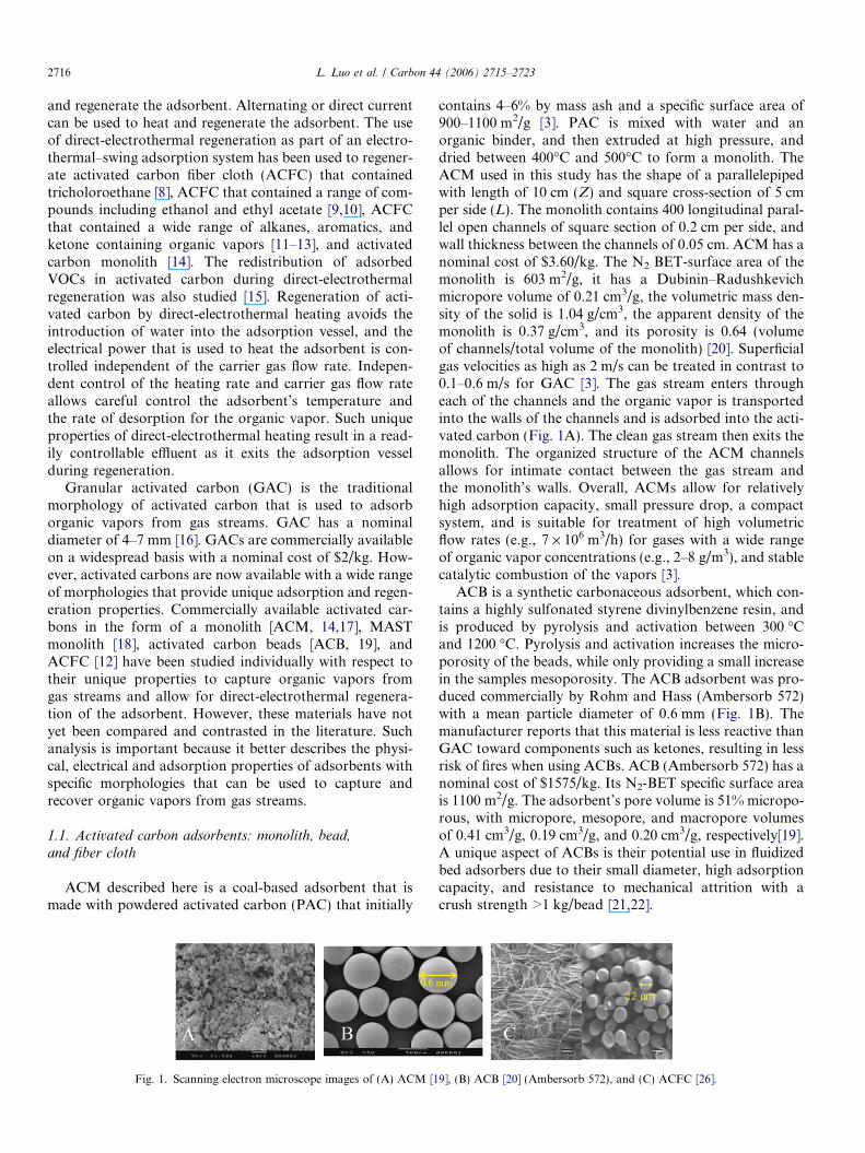
ACM described here is a coal-based adsorbent that ismade with powdered activated carbon (PAC) that initially
Fig. 1. Scanning electron microscope images of (A) ACM [1
contains 4–6% by mass ash and a specific surface area of900–1100 m2/g [3]. PAC is mixed with water and anorganic binder, and then extruded at high pressure, anddried between 400�C and 500�C to form a monolith. TheACM used in this study has the shape of a parallelepipedwith length of 10 cm (Z) and square cross-section of 5 cmper side (L). The monolith contains 400 longitudinal paral-lel open channels of square section of 0.2 cm per side, andwall thickness between the channels of 0.05 cm. ACM has anominal cost of $3.60/kg. The N2 BET-surface area of themonolith is 603 m2/g, it has a Dubinin–Radushkevichmicropore volume of 0.21 cm3/g, the volumetric mass den-sity of the solid is 1.04 g/cm3, the apparent density of themonolith is 0.37 g/cm3, and its porosity is 0.64 (volumeof channels/total volume of the monolith) [20]. Superficialgas velocities as high as 2 m/s can be treated in contrast to0.1–0.6 m/s for GAC [3]. The gas stream enters througheach of the channels and the organic vapor is transportedinto the walls of the channels and is adsorbed into the acti-vated carbon (Fig. 1A). The clean gas stream then exits themonolith. The organized structure of the ACM channelsallows for intimate contact between the gas stream andthe monolith’s walls. Overall, ACMs allow for relativelyhigh adsorption capacity, small pressure drop, a compactsystem, and is suitable for treatment of high volumetricflow rates (e.g., 7 · 106 m3/h) for gases with a wide rangeof organic vapor concentrations (e.g., 2–8 g/m3), and stablecatalytic combustion of the vapors [3].
ACB is a synthetic carbonaceous adsorbent, which con-tains a highly sulfonated styrene divinylbenzene resin, andis produced by pyrolysis and activation between 300 �Cand 1200 �C. Pyrolysis and activation increases the micro-porosity of the beads, while only providing a small increasein the samples mesoporosity. The ACB adsorbent was pro-duced commercially by Rohm and Hass (Ambersorb 572)with a mean particle diameter of 0.6 mm (Fig. 1B). Themanufacturer reports that this material is less reactive thanGAC toward components such as ketones, resulting in lessrisk of fires when using ACBs. ACB (Ambersorb 572) has anominal cost of $1575/kg. Its N2-BET specific surface areais 1100 m2/g. The adsorbent’s pore volume is 51% micropo-rous, with micropore, mesopore, and macropore volumesof 0.41 cm3/g, 0.19 cm3/g, and 0.20 cm3/g, respectively[19].A unique aspect of ACBs is their potential use in fluidizedbed adsorbers due to their small diameter, high adsorptioncapacity, and resistance to mechanical attrition with acrush strength >1 kg/bead [21,22].
9], (B) ACB [20] (Ambersorb 572), and (C) ACFC [26].
L. Luo et al. / Carbon 44 (2006) 2715–2723 2717
Activated carbon fibers (ACFs) are made from novo-loid, pitch, cellulose, rayon, polyacrylonitrile and saran.ACFs are shapeable and can be formed as activated carbonfiber paper, activated carbon fiber felt, and ACFC.ACFCs’ surface areas can range from 700 m2/g to2400 m2/g, which provides larger surface areas than com-monly used GACs [23]. ACFC used in this study is madefrom phenolic NovolacTM resin and is identified here asACFC-5092-20 (Model ACC-5092-20, American KynolInc., Pleasantville, NY, Fig. 1C). ACFC-5092-20 has anominal cost of $730/kg. The pores of ACFC are domi-nated by micropores (e.g., >93% by volume) with meantotal pore width ranging from 7.4 to 9.9 and microporepore width ranging from 6.9 A to 9.8 A, depending onthe lot of ACFC tested [24,25]. ACFC’s physical propertiesprovide rapid adsorption and high adsorption capacitiesfor a wide range of organic vapors [23,25]. Mass and heattransfer of vapors to and from the ACFCs are alsoenhanced because of their low nominal fiber diameter of12 lm [25]. The ACFC used here has an N2-BET surfacearea of 1604 m2/g, electrical resistivity of 6 · 10�3 X m at22 �C [25], and consists of 95.1% carbon, 0.4% hydrogen,4.5% oxygen, <0.05% nitrogen, and 0% ash by mass, asdetermined by ultimate analysis [25]. Ash free adsorbentsare useful to restrain unwanted chemical reactions and fireswithin the adsorption vessel that occur with typical GACsthat contain ash. The shapeable woven ACFC readily per-mit the formation of annular and pleated cartridges. Theseunique properties make ACFC a desirable adsorbent forgas separation and air pollution control applications.
1.2. Chemical and physical properties of the adsorbate
Toluene (C7H8) is used as the adsorbate for each of theadsorption systems discussed here. Toluene is an importantorganic vapor because it is a hazardous air pollutant and81 · 106 kg/yr of toluene is emitted to the atmosphere fromUSA [27]. Toluene is aromatic, with a molecular weight of92.1 g/mole, molecular diameter of 6.95 A, boiling pointof 110.6 �C, dipole moment of 0.4 Debyes, liquid density
N2 MFC
MixerV1
V2
Syringe pumps
Evaporator
MFC= Mass flow controller
N2 MFCN2 MFCN2 MFC
MixerV1
V2
Syringe pumps
Evaporator
MFC= Mass flow controller
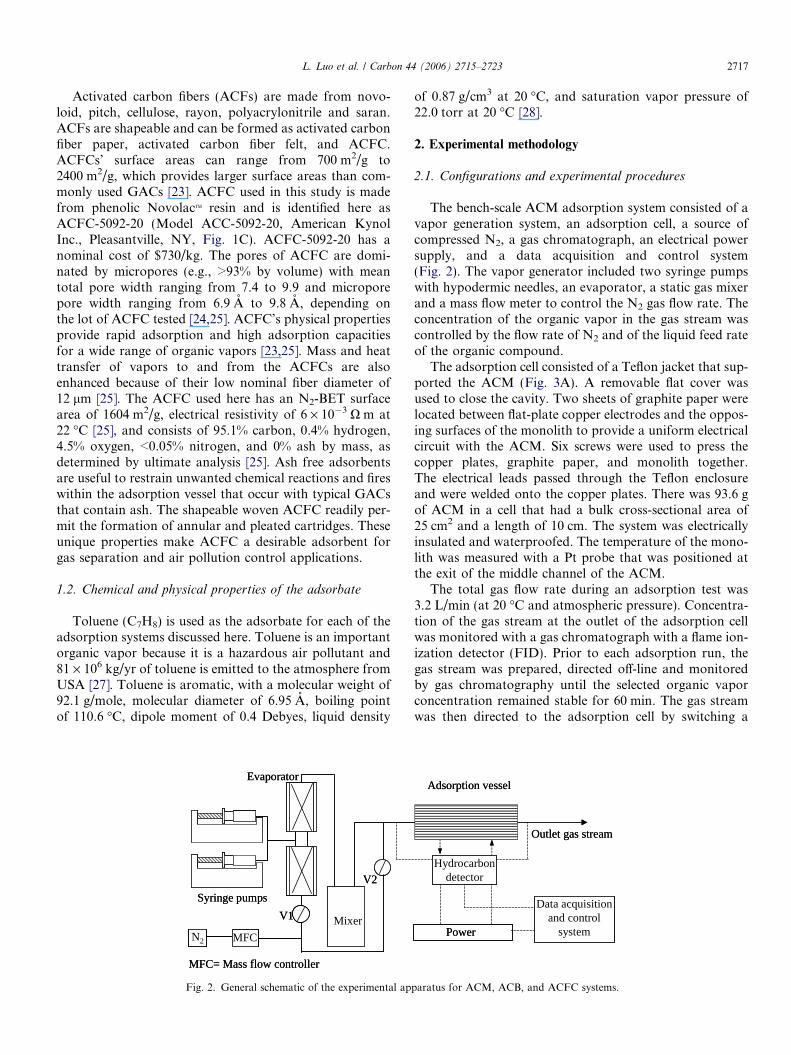
Fig. 2. General schematic of the experimental ap
of 0.87 g/cm3 at 20 �C, and saturation vapor pressure of22.0 torr at 20 �C [28].
2. Experimental methodology
2.1. Configurations and experimental procedures
The bench-scale ACM adsorption system consisted of avapor generation system, an adsorption cell, a source ofcompressed N2, a gas chromatograph, an electrical powersupply, and a data acquisition and control system(Fig. 2). The vapor generator included two syringe pumpswith hypodermic needles, an evaporator, a static gas mixerand a mass flow meter to control the N2 gas flow rate. Theconcentration of the organic vapor in the gas stream wascontrolled by the flow rate of N2 and of the liquid feed rateof the organic compound.
The adsorption cell consisted of a Teflon jacket that sup-ported the ACM (Fig. 3A). A removable flat cover wasused to close the cavity. Two sheets of graphite paper werelocated between flat-plate copper electrodes and the oppos-ing surfaces of the monolith to provide a uniform electricalcircuit with the ACM. Six screws were used to press thecopper plates, graphite paper, and monolith together.The electrical leads passed through the Teflon enclosureand were welded onto the copper plates. There was 93.6 gof ACM in a cell that had a bulk cross-sectional area of25 cm2 and a length of 10 cm. The system was electricallyinsulated and waterproofed. The temperature of the mono-lith was measured with a Pt probe that was positioned atthe exit of the middle channel of the ACM.
The total gas flow rate during an adsorption test was3.2 L/min (at 20 �C and atmospheric pressure). Concentra-tion of the gas stream at the outlet of the adsorption cellwas monitored with a gas chromatograph with a flame ion-ization detector (FID). Prior to each adsorption run, thegas stream was prepared, directed off-line and monitoredby gas chromatography until the selected organic vaporconcentration remained stable for 60 min. The gas streamwas then directed to the adsorption cell by switching a
Hydrocarbon detector
Power
Outlet gas stream
Adsorption vessel
Data acquisition and control
system
Hydrocarbon detector
Power
Outlet gas stream
Adsorption vessel
Data acquisition and control
system
paratus for ACM, ACB, and ACFC systems.
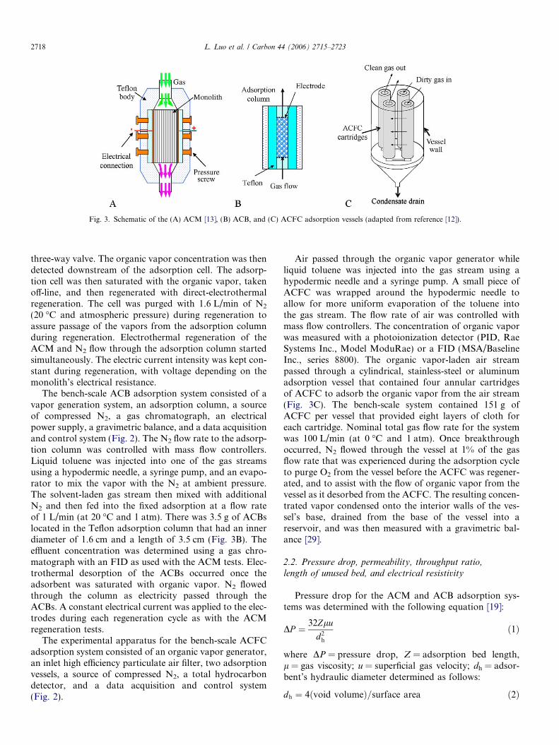
Fig. 3. Schematic of the (A) ACM [13], (B) ACB, and (C) ACFC adsorption vessels (adapted from reference [12]).
2718 L. Luo et al. / Carbon 44 (2006) 2715–2723
three-way valve. The organic vapor concentration was thendetected downstream of the adsorption cell. The adsorp-tion cell was then saturated with the organic vapor, takenoff-line, and then regenerated with direct-electrothermalregeneration. The cell was purged with 1.6 L/min of N2
(20 �C and atmospheric pressure) during regeneration toassure passage of the vapors from the adsorption columnduring regeneration. Electrothermal regeneration of theACM and N2 flow through the adsorption column startedsimultaneously. The electric current intensity was kept con-stant during regeneration, with voltage depending on themonolith’s electrical resistance.
The bench-scale ACB adsorption system consisted of avapor generation system, an adsorption column, a sourceof compressed N2, a gas chromatograph, an electricalpower supply, a gravimetric balance, and a data acquisitionand control system (Fig. 2). The N2 flow rate to the adsorp-tion column was controlled with mass flow controllers.Liquid toluene was injected into one of the gas streamsusing a hypodermic needle, a syringe pump, and an evapo-rator to mix the vapor with the N2 at ambient pressure.The solvent-laden gas stream then mixed with additionalN2 and then fed into the fixed adsorption at a flow rateof 1 L/min (at 20 �C and 1 atm). There was 3.5 g of ACBslocated in the Teflon adsorption column that had an innerdiameter of 1.6 cm and a length of 3.5 cm (Fig. 3B). Theeffluent concentration was determined using a gas chro-matograph with an FID as used with the ACM tests. Elec-trothermal desorption of the ACBs occurred once theadsorbent was saturated with organic vapor. N2 flowedthrough the column as electricity passed through theACBs. A constant electrical current was applied to the elec-trodes during each regeneration cycle as with the ACMregeneration tests.
The experimental apparatus for the bench-scale ACFCadsorption system consisted of an organic vapor generator,an inlet high efficiency particulate air filter, two adsorptionvessels, a source of compressed N2, a total hydrocarbondetector, and a data acquisition and control system(Fig. 2).
Air passed through the organic vapor generator whileliquid toluene was injected into the gas stream using ahypodermic needle and a syringe pump. A small piece ofACFC was wrapped around the hypodermic needle toallow for more uniform evaporation of the toluene intothe gas stream. The flow rate of air was controlled withmass flow controllers. The concentration of organic vaporwas measured with a photoionization detector (PID, RaeSystems Inc., Model ModuRae) or a FID (MSA/BaselineInc., series 8800). The organic vapor-laden air streampassed through a cylindrical, stainless-steel or aluminumadsorption vessel that contained four annular cartridgesof ACFC to adsorb the organic vapor from the air stream(Fig. 3C). The bench-scale system contained 151 g ofACFC per vessel that provided eight layers of cloth foreach cartridge. Nominal total gas flow rate for the systemwas 100 L/min (at 0 �C and 1 atm). Once breakthroughoccurred, N2 flowed through the vessel at 1% of the gasflow rate that was experienced during the adsorption cycleto purge O2 from the vessel before the ACFC was regener-ated, and to assist with the flow of organic vapor from thevessel as it desorbed from the ACFC. The resulting concen-trated vapor condensed onto the interior walls of the ves-sel’s base, drained from the base of the vessel into areservoir, and was then measured with a gravimetric bal-ance [29].
2.2. Pressure drop, permeability, throughput ratio,length of unused bed, and electrical resistivity
Pressure drop for the ACM and ACB adsorption sys-tems was determined with the following equation [19]:
DP ¼ 32Zlu
d2h
ð1Þ
where DP = pressure drop, Z = adsorption bed length,l = gas viscosity; u = superficial gas velocity; dh = adsor-bent’s hydraulic diameter determined as follows:
dh ¼ 4ðvoid volumeÞ=surface area ð2Þ
L. Luo et al. / Carbon 44 (2006) 2715–2723 2719
which results in dh = ACM channel’s side length for theACM system. However, for the ACB system,
dh ¼2e
3ð1� eÞ db ð3Þ
where e = apparent porosity of the ACBs in the adsorptionvessel, and db = diameter of an ACB [19].
Pressure drop for the ACFC adsorption system wasmeasured at the vessel’s inlet at select gas flow rates usinga U-tube manometer filled with water (Mod. 1222-8-W/M, Dwyer Inc.). Net pressure drop caused by the ACFCcartridge was determined by subtracting the pressure dropof the vessel without the ACFC adsorbent from the pres-sure drop of the vessel while containing the ACFCcartridge.
Permeability is a fluid flow parameter than characterizesthe flow of gases through the ACM, ACB and ACFCadsorbents [30]. The pressure drop (DP) through theACM and ACB adsorption systems can also be expressedas [31]:
DP ¼ qaCL2
� �u2 þ laL
ap
� �u ð4Þ
where qa = air density, C = inertial resistance factor,L = adsorbent’s length, la = air viscosity, and ap = perme-ability. Values of ap and C are determined by linear regres-sion with pressure drop data. Pressure drop for the ACFCsystem in the radial direction across the ACFC cartridges isas follows [31]:
DP ¼ qdC
8p2L2
1
ri
� 1
ro
� �� �Q2 þ la
2appLln
ro
ri
� �� �Q ð5Þ
where ri = inner radius of the cartridge, ro = outer radiusof the cartridge, and Q = gas flow rate through eachcartridge.
Values for throughput ratio (TPR) and the length ofunused bed (LUB) were calculated to assess the perfor-mance of the system during an adsorption cycle. HigherTPR values indicate a steeper breakthrough curve, wheretransient mass-transfer limitations become less impor-tant. As TPR approaches unity, the time needed for themass transfer zone to develop becomes insignificantcompared to the time needed to saturate the adsorbent.TPR is expressed as t5%/t50% where t5% = time requiredto achieve 5% breakthrough and t50% = time required toachieve 50% breakthrough. LUB describes the effectivefraction of the adsorbent that is not utilized when theadsorption cycle is stopped at 5% breakthrough. LUB isexpressed as 1- (m5%/m100%), where m5% = mass of theorganic vapor adsorbed at time t5% and m100% = massof the organic vapor adsorbed when the adsorbent issaturated.
Electrical resistivity (qr,o) is an intrinsic parameter thatcan be used to characterize the ACM, ACB, and ACFC.This parameter is dependent on the temperature, precursor,and degree of activation. The general equation describing
qr,o for a homogeneous conductor at a reference tempera-ture (TR) is defined as [32]:
qr;o ¼AL
� �R ð6Þ
where A = cross-sectional area perpendicular to the currentflow, R = electrical resistance, and L=length parallel to thecurrent flow.
Resistivity dependence on temperature is described by[32]:
qrðT Þ ¼ qr;oð1þ arðT � T RÞÞ ð7Þ
where T = adsorbent’s temperature and ar = thermal resis-tivity factor. Parameter ar is obtained by linear regression ofthe adsorbent’s electrical resistance at select temperatures.
The ACM, ACB, and ACFC adsorbents are heteroge-neous due to the voids caused by the channels within theACM, around each ACB, and between the individualACFs. The electrical resistivity is related to the electricalresistance (R) for the ACM by considering the monolithas a combination of basic cells in parallel and/or series asdescribed below [19]:
qr ¼ RZ 1þ e
1�ffiffiep
� ��1
ð8Þ
Resistivity for the ACB was determined by consideringthe resistance of a bead and the resistance of contactbetween two vertically adjacent beads, as described below[19]:
qr ¼ qbead;eff þ qcontact;effðpappÞ�d: ð9Þ
Where qbead,eff = Rbdb with Rb = bead’s electricalresistance,
qcontact;eff ¼K2d2
b
Zð10Þ
and papp = pressure applied to the adsorbent to improvethe electrical contact among the beads, d = 0.2 [19], andK2 = coefficient factor between the electrical resistance ofcontact and the applied pressure.
K2 ¼ Ricontactf
di ð11Þ
where Ricontact ¼ electrical resistance between two beads at
section element i, and
fi ¼ papp þ ði� 1Þbdb ð12Þ
(i � 1) = section element within the adsorption vessel, andb = bead’s apparent density within the adsorption vessel.
The electrical resistance for ACFC was determined byconsidering the effective ACFC thickness that is calculatedby dividing the areal mass density of the bulk ACFC (qa)with the true mass density of the fiber (qt) [23]:
H eff ¼qa
qt
ð13Þ
This effective thickness represents the thickness of a hypo-thetically homogeneous (no interyarn and intrayarn void
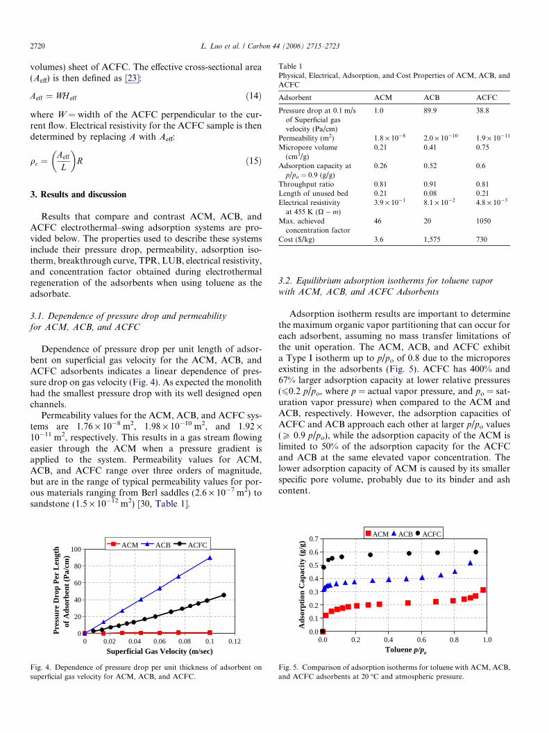
Table 1Physical, Electrical, Adsorption, and Cost Properties of ACM, ACB, andACFC
Adsorbent ACM ACB ACFC
Pressure drop at 0.1 m/sof Superficial gasvelocity (Pa/cm)
1.0 89.9 38.8
Permeability (m2) 1.8 · 10�8 2.0 · 10�10 1.9 · 10�11
Micropore volume(cm3/g)
0.21 0.41 0.75
Adsorption capacity at 0.26 0.52 0.6
2720 L. Luo et al. / Carbon 44 (2006) 2715–2723
volumes) sheet of ACFC. The effective cross-sectional area(Aeff) is then defined as [23]:
Aeff ¼ WH eff ð14Þ
where W = width of the ACFC perpendicular to the cur-rent flow. Electrical resistivity for the ACFC sample is thendetermined by replacing A with Aeff:
qr ¼Aeff
L
� �R ð15Þ
p/po = 0.9 (g/g)Throughput ratio 0.81 0.91 0.81Length of unused bed 0.21 0.08 0.21Electrical resistivity
at 455 K (X � m)3.9 · 10�1 8.1 · 10�2 4.8 · 10�3
Max. achievedconcentration factor
46 20 1050
Cost ($/kg) 3.6 1,575 730
3. Results and discussion
Results that compare and contrast ACM, ACB, andACFC electrothermal–swing adsorption systems are pro-vided below. The properties used to describe these systemsinclude their pressure drop, permeability, adsorption iso-therm, breakthrough curve, TPR, LUB, electrical resistivity,and concentration factor obtained during electrothermalregeneration of the adsorbents when using toluene as theadsorbate.
3.1. Dependence of pressure drop and permeability
for ACM, ACB, and ACFC
Dependence of pressure drop per unit length of adsor-bent on superficial gas velocity for the ACM, ACB, andACFC adsorbents indicates a linear dependence of pres-sure drop on gas velocity (Fig. 4). As expected the monolithhad the smallest pressure drop with its well designed openchannels.
Permeability values for the ACM, ACB, and ACFC sys-tems are 1.76 · 10�8 m2, 1.98 · 10�10 m2, and 1.92 ·10�11 m2, respectively. This results in a gas stream flowingeasier through the ACM when a pressure gradient isapplied to the system. Permeability values for ACM,ACB, and ACFC range over three orders of magnitude,but are in the range of typical permeability values for por-ous materials ranging from Berl saddles (2.6 · 10�7 m2) tosandstone (1.5 · 10�12 m2) [30, Table 1].
0
20
40
60
80
100
0 0.02 0.04 0.06 0.08 0.1 0.12
Superficial Gas Velocity (m/sec)
Pre
ssur
e D
rop
Per
Len
gth
of
Ads
orbe
nt (
Pa/
cm)
ACM ACB ACFC
Fig. 4. Dependence of pressure drop per unit thickness of adsorbent onsuperficial gas velocity for ACM, ACB, and ACFC.
3.2. Equilibrium adsorption isotherms for toluene vapor
with ACM, ACB, and ACFC Adsorbents
Adsorption isotherm results are important to determinethe maximum organic vapor partitioning that can occur foreach adsorbent, assuming no mass transfer limitations ofthe unit operation. The ACM, ACB, and ACFC exhibita Type I isotherm up to p/po of 0.8 due to the microporesexisting in the adsorbents (Fig. 5). ACFC has 400% and67% larger adsorption capacity at lower relative pressures(60.2 p/po, where p = actual vapor pressure, and po = sat-uration vapor pressure) when compared to the ACM andACB, respectively. However, the adsorption capacities ofACFC and ACB approach each other at larger p/po values(P 0.9 p/po), while the adsorption capacity of the ACM islimited to 50% of the adsorption capacity for the ACFCand ACB at the same elevated vapor concentration. Thelower adsorption capacity of ACM is caused by its smallerspecific pore volume, probably due to its binder and ashcontent.
0.0
0.1
0.2
0.3
0.4
0.5
0.6
0.7
0.0 0.2 0.4 0.6 0.8 1.0Toluene p/po
Ads
orpt
ion
Cap
acit
y (g
/g)
ACM ACB ACFC
Fig. 5. Comparison of adsorption isotherms for toluene with ACM, ACB,and ACFC adsorbents at 20 �C and atmospheric pressure.
0.001
0.01
0.1
1
250 300 350 400 450 500 550
Temperature (K)
Res
isti
vity
(oh
m-m
)
ACM ACB ACFC
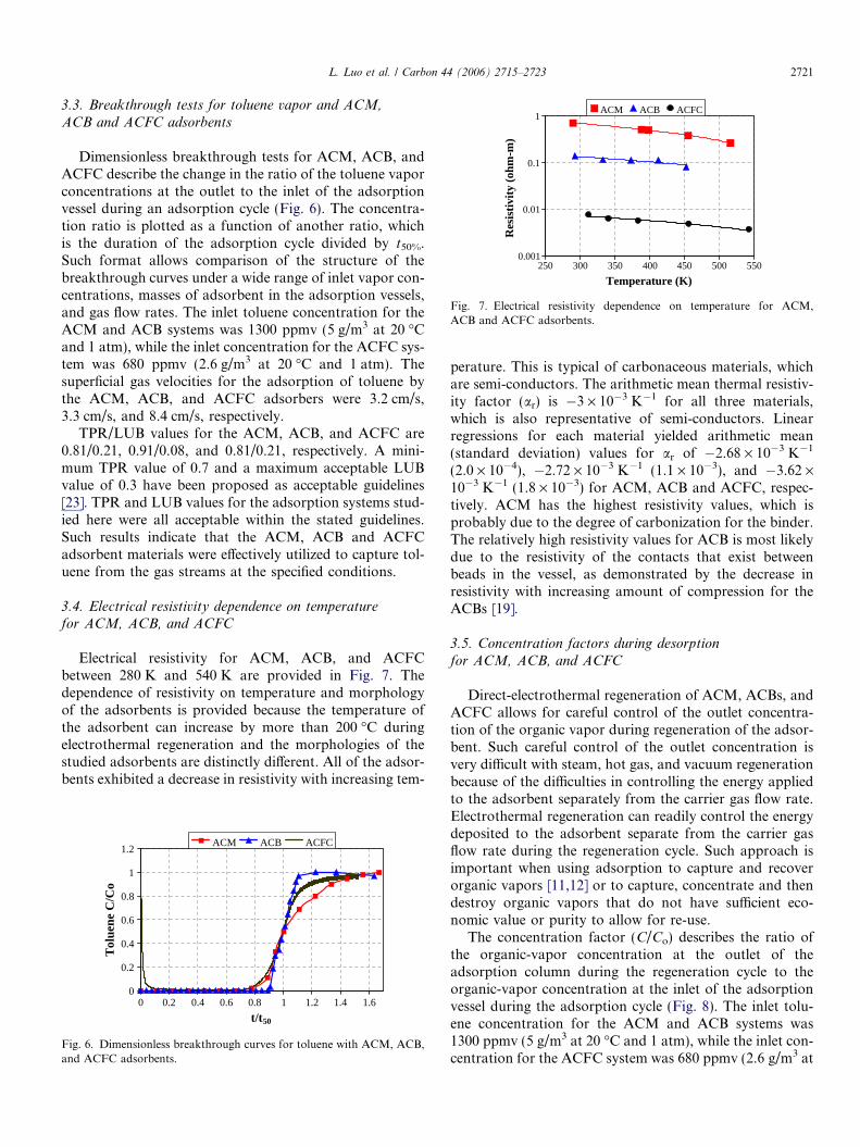
Fig. 7. Electrical resistivity dependence on temperature for ACM,ACB and ACFC adsorbents.
L. Luo et al. / Carbon 44 (2006) 2715–2723 2721
3.3. Breakthrough tests for toluene vapor and ACM,
ACB and ACFC adsorbents
Dimensionless breakthrough tests for ACM, ACB, andACFC describe the change in the ratio of the toluene vaporconcentrations at the outlet to the inlet of the adsorptionvessel during an adsorption cycle (Fig. 6). The concentra-tion ratio is plotted as a function of another ratio, whichis the duration of the adsorption cycle divided by t50%.Such format allows comparison of the structure of thebreakthrough curves under a wide range of inlet vapor con-centrations, masses of adsorbent in the adsorption vessels,and gas flow rates. The inlet toluene concentration for theACM and ACB systems was 1300 ppmv (5 g/m3 at 20 �Cand 1 atm), while the inlet concentration for the ACFC sys-tem was 680 ppmv (2.6 g/m3 at 20 �C and 1 atm). Thesuperficial gas velocities for the adsorption of toluene bythe ACM, ACB, and ACFC adsorbers were 3.2 cm/s,3.3 cm/s, and 8.4 cm/s, respectively.
TPR/LUB values for the ACM, ACB, and ACFC are0.81/0.21, 0.91/0.08, and 0.81/0.21, respectively. A mini-mum TPR value of 0.7 and a maximum acceptable LUBvalue of 0.3 have been proposed as acceptable guidelines[23]. TPR and LUB values for the adsorption systems stud-ied here were all acceptable within the stated guidelines.Such results indicate that the ACM, ACB and ACFCadsorbent materials were effectively utilized to capture tol-uene from the gas streams at the specified conditions.
3.4. Electrical resistivity dependence on temperaturefor ACM, ACB, and ACFC
Electrical resistivity for ACM, ACB, and ACFCbetween 280 K and 540 K are provided in Fig. 7. Thedependence of resistivity on temperature and morphologyof the adsorbents is provided because the temperature ofthe adsorbent can increase by more than 200 �C duringelectrothermal regeneration and the morphologies of thestudied adsorbents are distinctly different. All of the adsor-bents exhibited a decrease in resistivity with increasing tem-
0
0.2
0.4
0.6
0.8
1
1.2
0 0.2 0.4 0.6 0.8 1 1.2 1.4 1.6
t/t50
Tol
uene
C/C
o
ACM ACB ACFC
Fig. 6. Dimensionless breakthrough curves for toluene with ACM, ACB,and ACFC adsorbents.
perature. This is typical of carbonaceous materials, whichare semi-conductors. The arithmetic mean thermal resistiv-ity factor (ar) is �3 · 10�3 K�1 for all three materials,which is also representative of semi-conductors. Linearregressions for each material yielded arithmetic mean(standard deviation) values for ar of �2.68 · 10�3 K�1
(2.0 · 10�4), �2.72 · 10�3 K�1 (1.1 · 10�3), and �3.62 ·10�3 K�1 (1.8 · 10�3) for ACM, ACB and ACFC, respec-tively. ACM has the highest resistivity values, which isprobably due to the degree of carbonization for the binder.The relatively high resistivity values for ACB is most likelydue to the resistivity of the contacts that exist betweenbeads in the vessel, as demonstrated by the decrease inresistivity with increasing amount of compression for theACBs [19].
3.5. Concentration factors during desorption
for ACM, ACB, and ACFC
Direct-electrothermal regeneration of ACM, ACBs, andACFC allows for careful control of the outlet concentra-tion of the organic vapor during regeneration of the adsor-bent. Such careful control of the outlet concentration isvery difficult with steam, hot gas, and vacuum regenerationbecause of the difficulties in controlling the energy appliedto the adsorbent separately from the carrier gas flow rate.Electrothermal regeneration can readily control the energydeposited to the adsorbent separate from the carrier gasflow rate during the regeneration cycle. Such approach isimportant when using adsorption to capture and recoverorganic vapors [11,12] or to capture, concentrate and thendestroy organic vapors that do not have sufficient eco-nomic value or purity to allow for re-use.
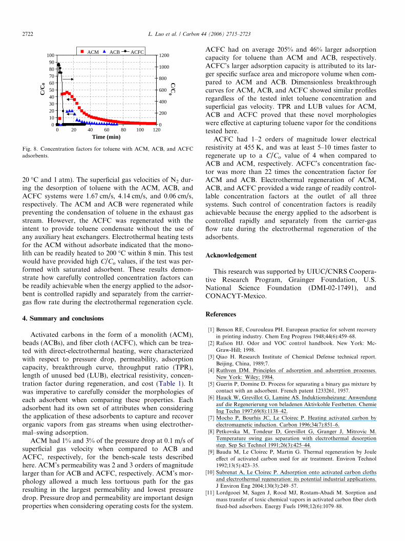
The concentration factor (C/Co) describes the ratio ofthe organic-vapor concentration at the outlet of theadsorption column during the regeneration cycle to theorganic-vapor concentration at the inlet of the adsorptionvessel during the adsorption cycle (Fig. 8). The inlet tolu-ene concentration for the ACM and ACB systems was1300 ppmv (5 g/m3 at 20 �C and 1 atm), while the inlet con-centration for the ACFC system was 680 ppmv (2.6 g/m3 at
0102030405060708090
100
0 20 40 60 80 100 120
Time (min)
C/C
0
0
200
400
600
800
1000
1200
C/C
0
ACM ACB ACFC
Fig. 8. Concentration factors for toluene with ACM, ACB, and ACFCadsorbents.
2722 L. Luo et al. / Carbon 44 (2006) 2715–2723
20 �C and 1 atm). The superficial gas velocities of N2 dur-ing the desorption of toluene with the ACM, ACB, andACFC systems were 1.67 cm/s, 4.14 cm/s, and 0.06 cm/s,respectively. The ACM and ACB were regenerated whilepreventing the condensation of toluene in the exhaust gasstream. However, the ACFC was regenerated with theintent to provide toluene condensate without the use ofany auxiliary heat exchangers. Electrothermal heating testsfor the ACM without adsorbate indicated that the mono-lith can be readily heated to 200 �C within 8 min. This testwould have provided high C/Co values, if the test was per-formed with saturated adsorbent. These results demon-strate how carefully controlled concentration factors canbe readily achievable when the energy applied to the adsor-bent is controlled rapidly and separately from the carrier-gas flow rate during the electrothermal regeneration cycle.
4. Summary and conclusions
Activated carbons in the form of a monolith (ACM),beads (ACBs), and fiber cloth (ACFC), which can be trea-ted with direct-electrothermal heating, were characterizedwith respect to pressure drop, permeability, adsorptioncapacity, breakthrough curve, throughput ratio (TPR),length of unused bed (LUB), electrical resistivity, concen-tration factor during regeneration, and cost (Table 1). Itwas imperative to carefully consider the morphologies ofeach adsorbent when comparing these properties. Eachadsorbent had its own set of attributes when consideringthe application of these adsorbents to capture and recoverorganic vapors from gas streams when using electrother-mal–swing adsorption.
ACM had 1% and 3% of the pressure drop at 0.1 m/s ofsuperficial gas velocity when compared to ACB andACFC, respectively, for the bench-scale tests describedhere. ACM’s permeability was 2 and 3 orders of magnitudelarger than for ACB and ACFC, respectively. ACM’s mor-phology allowed a much less tortuous path for the gasresulting in the largest permeability and lowest pressuredrop. Pressure drop and permeability are important designproperties when considering operating costs for the system.
ACFC had on average 205% and 46% larger adsorptioncapacity for toluene than ACM and ACB, respectively.ACFC’s larger adsorption capacity is attributed to its lar-ger specific surface area and micropore volume when com-pared to ACM and ACB. Dimensionless breakthroughcurves for ACM, ACB, and ACFC showed similar profilesregardless of the tested inlet toluene concentration andsuperficial gas velocity. TPR and LUB values for ACM,ACB and ACFC proved that these novel morphologieswere effective at capturing toluene vapor for the conditionstested here.
ACFC had 1–2 orders of magnitude lower electricalresistivity at 455 K, and was at least 5–10 times faster toregenerate up to a C/Co value of 4 when compared toACB and ACM, respectively. ACFC’s concentration fac-tor was more than 22 times the concentration factor forACM and ACB. Electrothermal regeneration of ACM,ACB, and ACFC provided a wide range of readily control-lable concentration factors at the outlet of all threesystems. Such control of concentration factors is readilyachievable because the energy applied to the adsorbent iscontrolled rapidly and separately from the carrier-gasflow rate during the electrothermal regeneration of theadsorbents.
Acknowledgement
This research was supported by UIUC/CNRS Coopera-tive Research Program, Grainger Foundation, U.S.National Science Foundation (DMI-02-17491), andCONACYT-Mexico.
References
[1] Benson RE, Courouleau PH. European practice for solvent recoveryin printing industry. Chem Eng Progress 1948;44(6):459–68.
[2] Rafson HJ. Odor and VOC control handbook. New York: Mc-Graw-Hill; 1998.
[3] Qiao H. Research Institute of Chemical Defense technical report.Beijing, China, 1989;7.
[4] Ruthven DM. Principles of adsorption and adsorption processes.New York: Wiley; 1984.
[5] Guerin P, Domine D. Process for separating a binary gas mixture bycontact with an adsorbent. French patent 1233261, 1957.
[6] Hauck W, Grevillot G, Lamine AS. Induktionsheizung: Anwendungauf die Regenerierung von beladenen Aktivkohle Festbetten. ChemieIng Techn 1997;69(8):1138–42.
[7] Mocho P, Bourhis JC, Le Cloirec P. Heating activated carbon byelectromagnetic induction. Carbon 1996;34(7):851–6.
[8] Petkovska M, Tondeur D, Grevillot G, Granger J, Mitrovic M.Temperature swing gas separation with electrothermal desorptionstep. Sep Sci Technol 1991;26(3):425–44.
[9] Baudu M, Le Cloirec P, Martin G. Thermal regeneration by Jouleeffect of activated carbon used for air treatment. Environ Technol1992;13(5):423–35.
[10] Subrenat A, Le Cloirec P. Adsorption onto activated carbon clothsand electrothermal regeneration: its potential industrial applications.J Environ Eng 2004;130(3):249–57.
[11] Lordgooei M, Sagen J, Rood MJ, Rostam-Abadi M. Sorption andmass transfer of toxic chemical vapors in activated carbon fiber clothfixed-bed adsorbers. Energy Fuels 1998;12(6):1079–88.
L. Luo et al. / Carbon 44 (2006) 2715–2723 2723
[12] Sullivan PD, Rood MJ, Grevillot G, Wander JD, Hay KJ. Activatedcarbon fiber cloth electrothermal swing adsorption system. EnvironSci Technol 2004;38(18):4865–77.
[13] Dombrowski KD, Lehmann CMB, Sullivan PD, Ramirez D, RoodMJ, Hay KJ. Solvent recovery and energy efficiency during electricregeneration of an ACF adsorber. J Environ Eng 2004;130(3):268–75.
[14] Yu F, Luo L, Grevillot G. electrothermal desorption using Jouleeffect on an activated carbon monolith. J Environ Eng 2004;130(3):242–8.
[15] Cheng ZM, Yu F, Grevillot G, Luo L, Yuan WK, Tondeur D.Redistribution of adsorbed VOCs in activated carbon under electro-thermal desorption. AIChE J 2002;48(5):1132–8.
[16] Smısek M, Cerny S. Active carbon: manufacture, properties andapplications. Czechoslovakia: Elsevier Pub Co; 1970.
[17] Yu F, Luo L, Grevillot G. Adsorption isotherms of VOCs ontomonolith activated carbon: experimental measurement and correla-tion with different models. J Chem Eng Data 2002;47(3):467–73.
[18] Tennison S, Blackburn A, Rawlinson T, Place R, Crittenden B,Perera S, et al. Electrically regenerable monolithic adsorption systemfor the recovery and recycle of solvent vapours. In: eighth funda-mental of adsorption. Sedona (Arizona. USA): 2004. p. 22–8.
[19] Saysset S. Procede d’adsorption sur adsorbant carbone avec regene-ration thermique par effet Joule direct. Application au traitementd’effluents charges en composes organiques volatils. Lorraine NancyFrance, L’Institut National Polytechnique de Lorraine, Ph.D. theses,1999.
[20] Yu F. Adsorption of organic volatile compounds with activatedcarbon monolith with electrothermal regeneration using the Jouleeffect. Lorraine Nancy France, L’Institut National Polytechnique deLorraine, Ph.D. theses, 2003.
[21] Duan W, Song WL, Luo L. Experimental study on VOCs adsorptionin a two-stage circulating fluidized bed. Chinese J Process Eng 2004;4(3):210–4.
[22] Song W, Tondeur D, Luo L, Li J. VOC adsorption in circulating gasfluidized bed. Adsorption 2005;11(1):853–8.
[23] Sullivan PD, Rood MJ, Hay KJ, Qi S. Adsorption and electrothermaldesorption of hazardous organic vapors. J Environ Eng 2001;127(3):217–23.
[24] Hsi HC, Rostam-Abadi M, Rood MJ, Chen S, Chang R. Effects ofsulfur impregnation temperature on the properties and mercuryadsorption capacities of activated carbon fibers. Environ Sci Technol2001;35(13):2785–91.
[25] Lo SY, Ramirez D, Rood M J, Hay KJ. Characterization of thephysical, thermal and adsorption properties of a series of activatedcarbon fiber cloths. In: Proceedings of the air and waste manage-ment’s 95th annual conference and exhibition. Baltimore, Maryland,USA: Air and Waste Management Association, 2002.
[26] Lo SY. Characterization of the chemical, physical, thermal andelectrical properties of a series of activated carbon fiber cloths.Urbana, IL, USA, University of Illinois at Urbana-Champaign,Master thesis, 2000.
[27] USEPA. EPA air pollution control cost manual. Research TrianglePark NC: US Environmental Protection Agency, 2002.
[28] Reid RC, Prausnitz JM, Poling BE. The properties of gases andliquids. 4th ed. New York: McGraw-Hill; 1987.
[29] Emamipour H, Kaldate A, Rood MJ, Thurston D. Experimentalstudy of cyclic adsorption/desorption of MEK in an ESA device. In:Proceedings of the air and waste management’s ninety-eighth annualconference and exhibition. Minneapolis, Minnesota, USA): Air andWaste Management Association; 2005.
[30] Collins RE. Flow of fluids through porous materials. New York:Reinhold Publishing Co.; 1961.
[31] FLUENT Version 6.0 User’s Guide Volumes 1 and 2: FLUENT Inc.;2001.
[32] Lindeburg MR. EIT review manual. San Carlos, CA: ProfessionalPublications; 1982.
Related Documents


