1. INTRODUCTION The objective of Aircraft Design Project II is to enhance the knowledge in continuation of the Aircraft Design Project I. It is more likely to perform an initial structural analysis as a part of the conceptual design process. Before the actual structural members can be sized and analyzed, the loads they will sustain must be determined. Aircraft loads estimation, a separate discipline of aerospace engineering, combines aerodynamics, structures and weights. The design process of the “Amphibious fighter” continues in the following stages. V-n diagram for the design study Gust and maneuverability envelopes Critical loading performance and final V-n graph calculation Structural design study – Theory approach Load estimation of wings Load estimation of fuselage Balancing and maneuvering loads on tail plane, aileron and rudder loads Detailed structural layouts Design of some components of wings, fuselage Preparation of a detailed design report with drawings 1.1 DATA FROM ADP – I 1.1.1 GENERAL CHARACTERISTICS Aircraft type : Amphibious fighter Crew : 1 Length : 24.80 m Span : 18.67 m Height : 8.77 m Empty weight : 15730 kg Total takeoff weight : 31430 kg Fuel weight : 9700 kg Engine model : Saturn/Lyulka AL-31 FM, Turbofan No. of engines : 2 1.1.2 PERFORMANCE CHARACTERISTICS Maximum speed : Mach 2 Cruise speed : Mach 0.85 Range : 2800 km Wing loading : 269.50 kg/m 2 Thrust/Weight : 0.956 Fuel capacity : 13.49m 3 Cruise Altitude : 10600 m 1

Adp II Batch III Report
Oct 21, 2015
ADP REPORT
Welcome message from author
This document is posted to help you gain knowledge. Please leave a comment to let me know what you think about it! Share it to your friends and learn new things together.
Transcript
1. INTRODUCTION
The objective of Aircraft Design Project II is to enhance the knowledge in continuation of the Aircraft Design Project I.
It is more likely to perform an initial structural analysis as a part of the conceptual design process. Before the actual structural members can be sized and analyzed, the loads they will sustain must be determined. Aircraft loads estimation, a separate discipline of aerospace engineering, combines aerodynamics, structures and weights. The design process of the “Amphibious fighter” continues in the following stages.
V-n diagram for the design study Gust and maneuverability envelopes Critical loading performance and final V-n graph calculation Structural design study – Theory approach Load estimation of wings Load estimation of fuselage Balancing and maneuvering loads on tail plane, aileron and rudder
loads Detailed structural layouts Design of some components of wings, fuselage Preparation of a detailed design report with drawings
1.1 DATA FROM ADP – I
1.1.1 GENERAL CHARACTERISTICS
Aircraft type : Amphibious fighterCrew : 1Length : 24.80 mSpan : 18.67 mHeight : 8.77 mEmpty weight : 15730 kgTotal takeoff weight : 31430 kgFuel weight : 9700 kg Engine model : Saturn/Lyulka AL-31 FM, TurbofanNo. of engines : 2
1.1.2 PERFORMANCE CHARACTERISTICS
Maximum speed : Mach 2Cruise speed : Mach 0.85Range : 2800 kmWing loading : 269.50 kg/m2
Thrust/Weight : 0.956Fuel capacity : 13.49m3
Cruise Altitude : 10600 m
1

1.1.3 CREW AND PAYLOAD REQUIREMENTS
No. of crew members = 1Weight of crew member = 100 kg (approx.)Weight of payload = 5900 kg
1.1.4 AIRFOIL SPECIFICATIONS
Airfoil type : NASA SC (2) – 0412
Thickness : 12.0%
Camber : 1.3%
Trailing edge angle : 3.6˚
Lower flatness : 4%
Leading edge radius : 2.3%
Maximum CL : 1.177
Maximum CL angle : 15.0
Maximum L/D : 23.492
Maximum L/D angle : 5.0
Maximum L/D CL : 0.902
Stall angle : 5.0
Zero-lift angle : -2.5
NASA SC(2)-0412 (Supercritical aerofoil)
2

Fig. 1.1 Lift for NASA SC(2)-0412
3

Fig. 1.2 Drag Polar for NASA SC(2)-04121.1.5 CONCEPTUAL DESIGN
4
2. V-n DIAGRAM FOR THE DESIGN STUDY
The largest load the aircraft is actually expected to encounter is called the limit, or applied load. To provide a margin of safety, the aircraft structure is always designed to withstand a higher load than the limit load. The highest load the structure is designed to withstand without braking is the “design” or “ultimate” load. The factor of safety is the multiplier used on limit load to determine the design load.
Many of the load requirements on aircraft are defined in terms of the load factor, n. The load factor is defined as the component of aerodynamic force perpendicular to the longitudinal axis divided by the aircraft weight. Assuming the angle of attack is not large, n = L/W. This is the effective perpendicular acceleration of the airplane in units of g, the acceleration due to gravity.
2.1 SIGNIFICANCE OF V-n DIAGRAM
There are structural limitations on the maximum load factor allowed for a given airplane. There are two categories of structural limitations in airplane design:
Limit Load Factor: This is the boundary associated with permanent structural deformation of one or more parts of the airplane. If n is less than the limit loadfactor, the structure may deflect during maneuver, but it will return to its original state when n = 1. If n is greater than the limit load factor, then the airplane structure will experience a permanent deformation, i.e., it will incur structural damage.
Ultimate Load Factor: This is the boundary associated with outright structural failure. If n is greater than the ultimate load factor, parts of the airplane will break.
Both the aerodynamic and structural limitations for an airplane are given by the V-n diagram, a plot of load factor versus flight velocity. A V-n diagram is a type of “flight envelope” for a given airplane. It establishes the maneuver boundaries.
For airplane design, the limit load factor depends on the type of aircraft. Some typical values of limit load factor are as follows.
AIRCRAFT TYPE npositive nnegative
Normal general aviation 2.5 to 3.8 -1.5 to -1Aerobatic aviation 6 -3Civil transport 3 to 4 -2 to -1Fighter 6.5 to 9 -6 to -3 Letnlim (positive) = 9nlim (negative) = -3
2.2 CALCULATION OF POSITIVE CURVE OF V-n DIAGRAM
5

VA - Design maneuvering speedVC - Design cruise speedVD - Design diving speedVS - Stalling speed
VS = 50 m/sVC = 291.55 m/s
VA = VS n
lim = 50 x 9 = 150 m/sVD = VC + 26.82 = 291.55 + 26.82 = 318.37 m/s
n = L/W
L = 2
1 ρ V2
S CL
Here ρ = 1.23 kg/m3
S = 99.13 m2
CL = 1.177W = 31430 kg
2.2.1 TAKEOFF, CRUISE AND LANDING
When V= 25 m/s
L = 2
1x 1.23 x 25² x 99.13 x 1.177 = 44847.34
n = 31430
34.44847 = 1.43
When V= 30 m/s
L = 2
1x 1.23 x 30² x 99.13 x 1.177 = 64580.17
n = 31430
17.64580 = 2.05
When V= 40 m/s
L = 2
1x 1.23 x 40² x 99.13 x 1.177 = 114809.19
n = 31430
19.114809 = 3.65
V m/s n25 1.4330 2.0540 3.65
6

2.3 CALCULATION OF NEGATIVE CURVE OF V-n DIAGRAM
VS = 50 m/sVC = 291.55 m/s
VA = VS n
lim = 50 x 3 = 86.6 m/sVD = VC + 26.82 = 291.55 + 26.82 = 318.37 m/s
n = L/W
L = 2
1 ρ V2
S CL
Hereρ = 1.23 kg/m3
S = 99.13 m2
CL = 0.3W = 31430 kg
2.3.1 TAKEOFF, CRUISE AND LANDING
When V= 25 m/s
L = 2
1x 1.23 x 25² x 99.13 x 0.3 = 11430.93
n = 31430
93.11430 = 0.36
When V= 30 m/s
L = 2
1x 1.23 x 30² x 99.13 x 0.3 = 16460.54
n = 31430
54.16460 = 0.52
When V= 40 m/s
L = 2
1x 1.23 x 40² x 99.13 x 0.3 = 29263.18
n = 31430
18.29263 = 0.93
V m/s n’25 0.3630 0.5240 0.93
7

2.4 OBTAINED V-n DIAGRAM
Fig. 2.3 Obtained V-n diagram (Takeoff, cruise and landing)
8

3. GUST AND MANEUVERABILITY ENVELOPE
The loads experienced when the aircraft encounters a strong gust can exceed the maneuver loads in some cases. When an aircraft experiences a gust, the effect is an increase (or decrease) in angle of attack. The change in angle of attack is approximately upward gust velocity divided by aircraft velocity. The change in aircraft lift is proportional to the gust velocity. The resulting change in load factor is given by
∆n = S
W2
uVCLρ ----------------------------------- Eqn. 5.1
where ∆n = Change in load factorρ = Density at sea levelu = Gust velocityV = Flight velocity
Eqn. 5.1 assume that the aircraft instantly encounters the gust and that it instantly affects the entire aircraft. These assumptions are unrealistic.
Gusts tend to follow a cosine-like intensity increase as the aircraft flies through, allowing it more time to react to the gust. This reduces the acceleration experienced by the aircraft by as much as 40%. To account for this effect a statistical gust alleviation factor (K) has been devised and applied to measured gust data (Ude)
U = K Ude
where
K = 03.1
03.1
95.6 µµ
× ( supersonic)
µ =
max
2
LgcCS
W
ρ
where µ = Equivalent mass ratioc = Average chord from wing designg = Acceleration due to gravity
The mass ratio term accounts for the fact that a small, light plane encounters the gust more rapidly than a larger plane.
9

At altitude less than 6100 m,
FLIGHT CONDITION µ K u (m/s)
High AOA 7.059 0.518 10.43Level flight 3.518 0.34 5.25Dive condition 3.326 0.33 2.527
3.1 POSITIVE LIMIT LOAD FACTOR
Considering positive limit load factor
FLIGHT CONDITION FLIGHT VELOCITY (m/s) ∆n npeak
High AOA 150 2.58 9.08Level flight 291.55 4.68 11.18Dive condition 318.37 1.24 7.74
3.2 NEGATIVE LIMIT LOAD FACTOR
Considering negative limit load factor
FLIGHT CONDITION FLIGHT VELOCITY (m/s) ∆n npeak
High AOA 86.6 0.38 3.38Level flight 291.55 1.19 4.19Dive condition 318.37 0.32 3.32
3.3 V-n DIAGRAM (GUST)
In equation 5.1 load factor due to gust increases if the aircraft is lighter. This is counter to the natural assumption that an aircraft is more likely to have a structural failure if it is heavily loaded.
In fact, the change in lift due to gust is unaffected by aircraft weight, so the change in wing stress is the same in either case. However, if the aircraft is lighter the same lift increase will cause a greater vertical acceleration (load factor) so the rest of then aircraft will experience more wing stress.
Aeroelastic effects can also influence the load factor due to gusts. An aft-swept wing will bend up under load, which twists the wing and reduces the outboard angle of attack. This reduces the total lift and also moves the spanwise lift distribution inboard, reducing the wing bending stress. An aft-swept wing experience roughly 15% lower load factor due to a given gust than an unswept wing.
10

V (m/s) n n’
0 1 186.6 - 3.38150 9.08 -
291.55 11.18 4.19318.37 7.74 3.32318.37 0 0
The gust load factors as calculated can be plotted on a V-n diagram.
Fig. 3.1 V-n Diagram (Gust)
In this diagram, it is assumed that the aircraft is in 1-g level flight when the gust is experienced.
3.4 COMBINED V-n DIAGRAM
11

The V-n diagrams of Figs. 2.3 and 3.1 are combined to determine the most critical limit load factor at each step. Since the gust loads are greater than the assumed limit load, it may be desirable to raise the assumed limit load at all velocities, as shown by the dotted line.
Fig. 3.1 Combined V-n Diagram
12

4. CRITICAL LOADING PERFORMANCE AND FINAL V-n GRAPH CALCULATION
The greatest air loads on an aircraft usually come from the generation of lift during high-g maneuvers. Even the fuselage is almost always structurally sized by the lift of the wing rather than by the air pressures produced directly on the fuselage. Aircraft load factor (n) expresses the maneuvering of an aircraft as a multiple of the standard acceleration due to gravity. At lower speeds the highest load factor an aircraft may experience is limited by the maximum lift available. At higher speeds maximum load factor is limited to some arbitrary values based upon the expected use of the aircraft.
The load factor for minimum radius of turn is given by
minRn = 2
0,
)/(
42
WT
KCD−
From ADP-IK = 0.05
0,DC = 0.015
WT = 0.956
minRn = 2)956.0(
015.005.042 ××−= 1.49
The load factor for maximum radius of turn is given by
maxRn = 1)/(
0,
−DKC
WT= 1
015.005.0
)956.0( −×
= 2.49
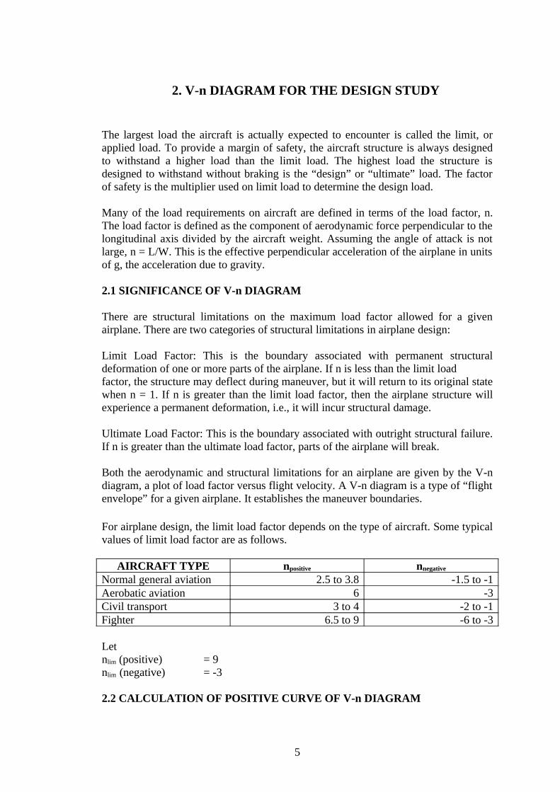
4.1 MANEUVERING LOAD FACTOR DIAGRAM
VA - Design maneuvering speedVC - Design cruise speedVD - Design diving speedVS - Stalling speedGW - Flight design gross weight
Vs =
max
2
NCS
GW
ρ
=
181.1364.013.99
314302
×
= 238.40 m/s
where
maxNC = { } { } 2max
2max CLDL CC −+
13
= { } { } 22 095.0177.1 +
= 1.181
Vc = S
GWKc =
13.99
3143036 = 641.02 m/s
where Kc= is a constant and it takes the value of 36 for fighter aircrafts
VD = 1.25x Vc =1.25x 641.02 = 801.28 m/s
VA = VS n
lim = 238.40 9 = 715.2 m/s
Fig. 4.1 Maneuvering load factor diagram
4.2 CONSTRAINTS ON LOAD FACTOR
The maximum possible load factor (at V= 50 m/s) is given by
maxn = ( )
−
SW
CV
W
T
SWK
VD 0,2
max
2
2
12
1
ρρ
14

=( )
×××−
××
05.317
015.05023.1
2
1956.0
05.31705.0
5023.12
12
2
= 9.25
maxn = 9.25
4.3 LEVEL TURN
Turn radius R = 12
2
−∞
ng
V
Turn rate ω = ∞
−V
ng 12
At V= 50 m/s
Turn radius R = 125.981.9
502
2
−= 27.71 m
Turn rate ω = 50
125.981.9 2 − = 1.80 rad/s
By calculationVelocity m/s Turn radius m Turn rate (rad/s)
50 27.71 1.80100 110.85 0.90150 249.42 0.60200 443.40 0.45250 692.83 0.36300 997.67 0.30350 1357.94 0.26400 1773.63 0.22450 2244.76 0.20500 2771.31 0.18
4.4 PULL UP MANEUVER
Turn radius R = ( )1
2
−∞
ng
V
Turn rate ω = ( )
∞
−V
ng 1
At V= 50 m/s
15

Turn radius R = ( )125.981.9
502
−= 30.89 m
Turn rate ω = ( )50
125.981.9 −= 1.62 rad/s
By calculationVelocity m/s Turn radius m Turn rate (rad/s)
50 30.89 1.62100 123.56 0.81150 278.00 0.54200 494.24 0.40250 772.25 0.32300 1112.04 0.26350 1513.60 0.23400 1976.96 0.20450 2502.08 0.18500 3088.99 0.16
4.5 PULL DOWN MANEUVER
Turn radius R = ( )1
2
+∞
ng
V
Turn rate ω = ( )
∞
+V
ng 1
At V= 50 m/s
Turn radius R = ( )125.981.9
502
+= 24.86 m
Turn rate ω = ( )50
125.981.9 += 2.01 rad/s
By calculation
Velocity m/s Turn radius m Turn rate (rad/s)50 24.86 2.01100 99.45 1.00150 223.76 0.67200 397.80 0.50250 621.56 0.40300 895.05 0.34350 1218.27 0.29400 1591.20 0.25450 2013.87 0.22500 2486.26 0.20
16

5. STRUCTURAL DESIGN STUDY – THEORY APPROACH
Structural design is of critical importance to aircraft safety, but also plays a key role in aircraft cost and performance. In addition to its direct impact on aircraft cost, the aircraft structural weight affects performance.
Before the structure can be designed, we need to determine the loads that will be imposed on the aircraft. Each part of the aircraft is subject to many different loads. In the final design of an aircraft structure, one might examine tens of thousands of loading conditions of which several hundred may be critical for some part of the airplane.
In addition to the obvious loads such as wing bending moments due to aerodynamic lift, many other loads must be considered. These include items such as inertia relief, the weight and inertial forces that tend to reduce wing bending moments, landing loads and taxi-bump loads, pressurization cycles on the fuselage, etc.
The aircraft (fighter) is designed such that it has amphibious characteristics and possess
RAPT system
Supercruise
Thrust vector and reverser
Delta wing
Stealth technology
5.1 AMPHIBIAN REQUIREMENTS
Buoyant
Statically stable when sitting in water
Dynamically stable when moving in water
Minimize water spray impingement
5.2 DELTA WING
The delta wing is a wing plan form in the form of a triangle. The primary advantage of the delta wing is that with a large enough angle of rearward sweep the wing’s leading edge will not contact the shock wave boundary formed at the nose of the fuselage as the speed of the aircraft approaches and exceeds transonic to supersonic velocity. The rearward sweep angle vastly lowers the airspeed normal to the leading edge of the wing, thereby allowing the aircraft to fly at high subsonic, transonic, or supersonic speed, while the over wing speed of the lifting air is kept to less than the speed of sound.
17

The delta plan form gives the largest total wing area (generating useful lift) for the wing shape, with very low wing per-unit loading, permitting high maneuverability in the airframe. As the delta's platform carries across the entire aircraft, it can be built much more strongly than a swept wing, where the spar meets the fuselage far in front of the center of gravity. Generally a delta will be stronger than a similar swept wing, as well as having much more internal volume for fuel and other storage.
Another advantage is that as the angle of attack increases the leading edge of the wing generates a vortex which energizes the flow, giving the delta a very high stall angle. A normal wing built for high speed use is typically dangerous at low speeds, but in this regime the delta changes over to a mode of lift based on the vortex it generates.
Additional advantages of the delta wing are simplicity of manufacture, strength, and substantial interior volume for fuel or other equipment. Because the delta wing is simple, it can be made very robust (even if it is quite thin), and it is easy and relatively inexpensive to build.
The delta wing variant used here is a near-cropped delta(tailed). Cropped delta has its tip cut off. This helps to avoid tip drag at high angles of attack.
5.3 STRUCTURAL DESIGN CRITERIA
(a) Strength requirements are specified in terms of limit loads (the maximum loads to be expected in service) and ultimate loads (limit loads multiplied by prescribed factors of safety). Unless otherwise provided, prescribed loads are limit loads.
(b) The specified air, ground, and water loads must be placed in equilibrium with inertia forces, considering each item of mass in the airplane. These loads must be distributed to conservatively approximate or closely represent actual conditions. Methods used to determine load intensities and distribution must be validated by flight load measurement unless the methods used for determining those loading conditions are shown to be reliable.
(c)If deflections under load would significantly change the distribution of external or internal loads, this redistribution must be taken into account. Factor of safety:A factor of safety of 1.5 must be applied to the prescribed limit loads which are considered external loads on the structure. When a loading condition is prescribed in terms of ultimate loads, a factor of safety need not be applied.
Strength and deformation:(a) The structure must be able to support limit loads without detrimental
permanent deformation. At any load up to limit loads, the deformation may not interfere with safe operation.
(b) The structure must be able to support ultimate loads without failure for at least 3 seconds. Static tests conducted to ultimate load must include the ultimate deflections and ultimate deformation induced by the loading. When analytical methods are used to show compliance with the ultimate load strength requirements, it must be shown that
18
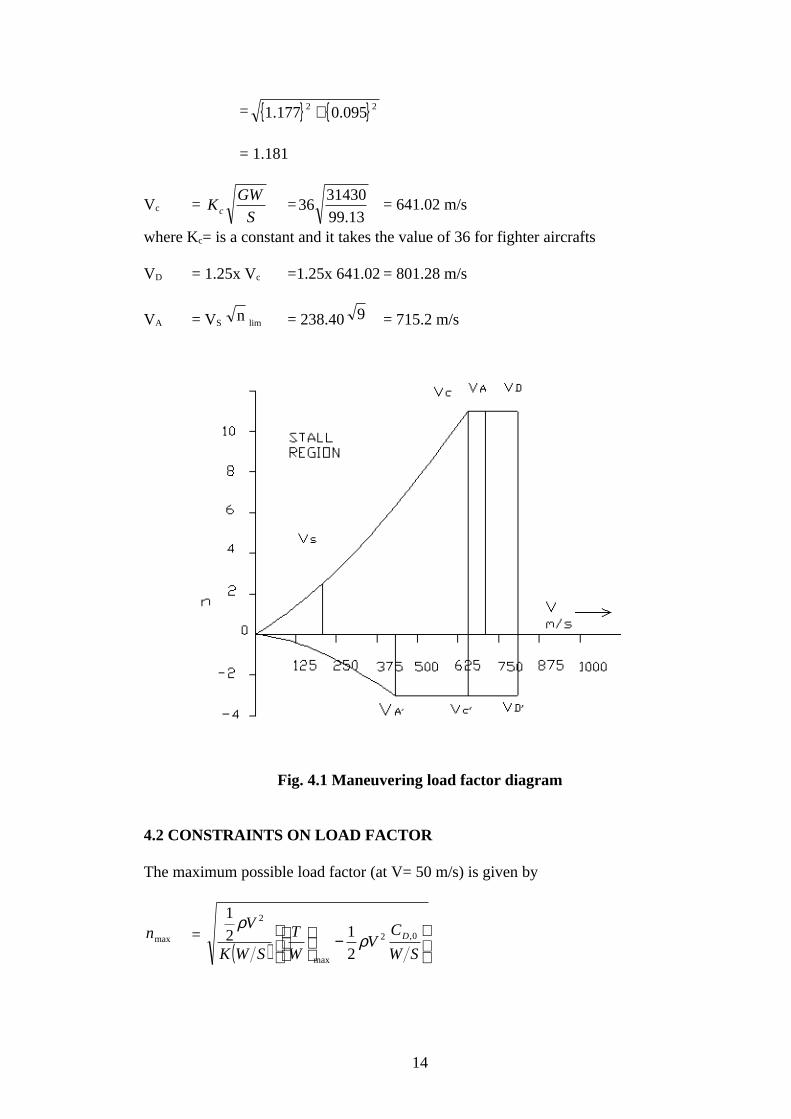
(1) The effects of deformation are not significant; (2) The deformations involved are fully accounted for in the analysis; or (3) The methods and assumptions used are sufficient to cover the effects of these deformations.
(c) Where structural flexibility is such that any rate of load application likely to occur in the operating conditions might produce transient stresses appreciably higher than those corresponding to static loads, the effects of this rate of application must be considered. Unless shown to be extremely improbable, the airplane must be designed to withstand any forced structural vibration resulting from any failure, malfunction or adverse condition in the flight control system.
5.4 CONTINUOUS GUST DESIGN CRITERIA
The continuous gust design criteria must be used in establishing the dynamic response of the airplane to vertical and lateral continuous turbulence. The following gust load requirements apply to mission analysis and design envelope analysis:
(a) The limit gust loads must be determined utilizing the continuous turbulence concept. (b) In design envelope analysis all critical altitudes, weights, and weight distributions, and all critical speeds must be considered.
5.5 AIRCRAFT STRUCTURAL DESIGN
Although the major focus of structural design in the early development of aircraft was on strength, now structural designers also deal with fail-safety, fatigue, corrosion, maintenance and inspectability, and produceability.
Structural Concepts:
Modern aircraft structures are designed using a semi-monocoque concept- a basic load-carrying shell reinforced by frames and longerons in the bodies, and a skin-stringer construction supported by spars and ribs in the surfaces.
Proper stress levels, a very complex problem in highly redundant structures, are calculated using versatile computer matrix methods to solve for detailed internal loads. Modern finite element models of aircraft components include tens-of-thousands of degrees-of-freedom and are used to determine the required skin thicknesses to avoid excessive stress levels, deflections, strains, or buckling.
The goals of detailed design are to reduce or eliminate stress concentrations, residual stresses, fretting corrosion, hidden undetectable cracks, or single failure causing component failure.
Open sections, such as Z or J sections, are used to permit inspection of stringers and avoid moisture accumulation. Fail-safe design is achieved through material selection, proper stress levels, and multiple load path structural arrangements which maintain high strength in the presence of a crack or damage.
19

Examples of the latter are:
a) Use of tear-stoppers
b) Spanwise wing and stabilizer skin splices
5.6 DESIGN LIFE CRITERIA
Fatigue failure life of a structural member is usually defined as the time to initiate a crack which would tend to reduce the ultimate strength of the member.
Fatigue design life implies the average life to be expected under average aircraft utilization and loads environment. To this design life, application of a fatigue life scatter factor accounts for the typical variations from the average utilization, loading environments, and basic fatigue strength allowables. This leads to a safe-life period during which the probability of a structural crack occurring is very low. With fail-safe, inspectable design, the actual structural life is much greater. The overall fatigue life of the aircraft is the time at which the repair of the structure is no longer economically feasible.
5.7 MATERIALS
Choice of materials emphasizes not only strength/weight ratio but also:
Fracture toughness Crack propagation rate Notch sensitivity Stress corrosion resistance Exfoliation corrosion resistance
Acoustic fatigue testing is important in affected portions of structure. Doublers are used to reduce stress concentrations around splices, cut-outs, doors, windows, access panels, etc., and to serve as tear-stoppers at frames and longerons.
Generally DC-10 uses 2024-T3 aluminum for tension structure such as lower wing skins, pressure critical fuselage skins and minimum gage applications. This material has excellent fatigue strength, fracture toughness and notch sensitivity. 7075-T6 aluminum has the highest strength with acceptable toughness. It is used for strength critical structures such as fuselage floor beams, stabilizers and spar caps in control surfaces. It is also used for upper wing skins.
For those parts in which residual stresses could possibly be present, 7075-T73 material is used. 7075-T73 material has superior stress corrosion resistance and exfoliation corrosion resistance, and good fracture toughness. Typical applications are fittings that can have detrimental preloads induced during assembly or that are subjected to sustained operational loads. Thick-section forgings are 7075-T73, due to the possible residual stresses induced during heat treatment. The integral ends of
20

7075-T6 stringers and spar caps are over aged to T73 locally. This unique use of the T73 temper virtually eliminates possibility of stress corrosion cracking in critical joint areas.
Composites:
Composites are the most important materials to be adapted for aviation. Composites are materials that are combinations of two or more organic or inorganic components. One material serves as a "matrix," which is the material that holds everything together, while the other material serves as reinforcement, in the form of fibers embedded in the matrix. Until recently, the most common matrix materials were "thermosetting" materials such as epoxy, bismaleimide, or polyimide. The reinforcing materials can be glass fiber, boron fiber, etc.
Fiberglass is the most common composite material, and consists of glass fibers embedded in a resin matrix. Fiberglass was first used widely for boats and automobiles, and today most cars have fiberglass bumpers covering a steel frame. Fiberglass was first used in the Boeing 707 passenger jet, where it comprised about two percent of the structure. Later, other composite materials became available, in particular boron fiber and graphite, embedded in epoxy resins.
Making composite structures is more complex than manufacturing most metal structures. To make a composite structure, the composite material, in tape or fabric form, is laid out and put in a mould under heat and pressure. The resin matrix material flows and when the heat is removed, it solidifies. It can be formed into various shapes. In some cases, the fibers are wound tightly to increase strength.
One useful feature of composites is that they can be layered, with the fibers in each layer running in a different direction. This allows materials engineers to design structures that behave in certain ways. The greatest value of composite materials is that they can be both lightweight and strong. The heavier an aircraft weighs, the more fuel it burns, so reducing weight is important to aeronautical engineers.
Despite their strength and low weight, composites have not been a miracle solution for aircraft structures. Composites are hard to inspect for flaws. Some of them absorb moisture. Most importantly, they can be expensive, primarily because they are labour intensive and often require complex and expensive fabrication machines.
Modern military aircraft, such as the F-22, use composites for at least a third of their structures, and some experts have predicted that future military aircraft will be more than two-thirds composite materials
Material Selection:
The wing spars are composed of a high strength unidirectional graphite/epoxy composite material chosen for its high strength and low weight. The fuselage bulkheads are made of a high strength aluminium alloy. This arrangement was chosen through a trade study to determine the optimum balance between overall structural weight and cost. Because of its stealth and torsional strength characteristics, a high modulus graphite/epoxy was also selected for the aircraft skin.
21

A further use of advanced composites is the placement of 1/2-inch Kevlar armour around the engines. This was done to improve survivability since the aircraft spends much of its time at low levels where critical systems must be protected from battle damage. In the design of any part of the aircraft it is essential to know accurately the properties of the material used.
Young's modulus: It is the ratio of stress to strain and is constant for and isotropic material in all directions. Poisson's ratio: It is the ratio of transverse strain to longitudinal strain on application of longitudinal stress. Yield strength: It is the maximum stress the material can take in the elastic region of loading.
Ultimate stress: It is defined as the maximum stress the material can withstand beyond which it will completely fail.
Shear strength: It is the maximum shear stress the material can withstand beyond which it will completely fail.
Key Properties:
Typical properties of aluminium alloy 6061 include:
Medium to high strength Good toughness Good surface finish Excellent corrosion resistance to atmospheric conditions Good corrosion resistance to sea water Can be anodized Good weldability and brazability Good workability Widely available
Kevlar:
Kevlar is the registered trademark for a para-aramid synthetic fiber, related to other aramids such as Nomex and Technora. This high strength material was first commercially used as a replacement for steel in racing tires. Typically it is spun into ropes or fabric sheets that can be used as such or as an ingredient in composite material components. Currently, Kevlar has many applications, ranging from bicycle tires and racing sails to body armor because of its high tensile strength-to-weight ratio. When used as a woven material, it is suitable for mooring lines and other underwater applications.
Boron fiber:
Specialty Materials’ boron fiber is particularly desirable for use in aerospace industry applications where high compression loads are present. Some examples of these applications include the following aircraft: F-15 Fighter, F-14 Fighter, B1 Bomber, Blackhawk Helicopter, Predator B UAV, and the Space Shuttle.
22

Radar-absorbent material:
Radar-absorbent material, or RAM, is a class of materials used in stealth technology to disguise a vehicle or structure from radar detection. A material's absorbency at a given frequency of radar wave depends upon its composition. RAM cannot perfectly absorb radar at any frequency, but any given composition does have greater absorbency at some frequencies than others; there is no one RAM that is suited to absorption of all radar frequencies
A common misunderstanding is that RAM makes an object invisible to radar. A radar absorbent material can significantly reduce an object's radar cross-section in specific radar frequencies, but it does not result in "invisibility" on any frequency. Bad weather may contribute to deficiencies in stealth capability. RAM is only a part of achieving stealth.
5.8 STRUCTURAL OPTIMIZATION AND DESIGN
Structures are often analyzed using complex finite element analysis methods. These tools have evolved over the past decades to be the basis of most structural design tasks. A candidate structure is analyzed subject to the predicted loads and the finite element program predicts deflections, stresses, strains, and even buckling of the many elements. The designed can then resize components to reduce weight or prevent failure. In recent years, structural optimization has been combined with finite element analysis to determine component gauges that may minimize weight subject to a number of constraints. Such tools are becoming very useful and there are many examples of substantial weight reduction using these methods.
23

6. LOAD ESTIMATION OF WINGS
6.1 AIRLOADS ON LIFTING SURFACES
The actual loads and load distributions on the lifting surfaces can be determined. The first step involves the stability-and-control calculation to determine the required lift on the horizontal tail to balance the wing pitching moment at the critical conditions. The required tail lift will increase or decrease the required wing lift to attain the same load factor.
Complicated methods for estimating the lift on the trimmed tail and wing for a given load factor can be initially approximated by a simple summation of wing and tail moments about the aircraft center of gravity, ignoring the effects of downwash, thrust axis, etc.
Once the total lift in the wing and tail are known, the spanwise and chordwise load distributions can be determined. For initial design, classical approximation methods give reasonably good results.
Fig. 6.1 Wing lift distribution
According to classical wing theory, the spanwise lift (or load) distribution is proportional to the circulation at each span station. A vortex lifting-line calculation will yield the spanwise lift distribution. For an elliptical planform wing, the lift and load distribution is of elliptical shape.
24

For a non-elliptical wing, a good semi-empirical method for spanwise load estimation is known as Schrenk’s approximation. This method assumes that the load distribution on an untwisted wing or tail has a shape that is the average of the actual planform shape and an elliptic shape of the same span and area.
Fig. 6.2 Schrenk’s approximation
In the above figure load is assumed to continue to the centerline of the aircraft.
The total area under the lift load curve must sum to the required total lift. The following equation describes the chord distribution of an elliptical wing.
)( yC = 2
21
4
−
b
y
b
S
π
From ADP-IS = 99.13 m2
b = 18.67 m
The chord distribution is as follows.
y C(y)1.87 6.623.73 6.205.60 5.417.47 4.059.33 0
6.2 ELLIPTICALLLY LOADED WINGIt turns out that an elliptically loaded wing has the lowest possible induced drag for a given wing aspect ratio, and lift coefficient. Aerodynamic designers strive to achieve
25
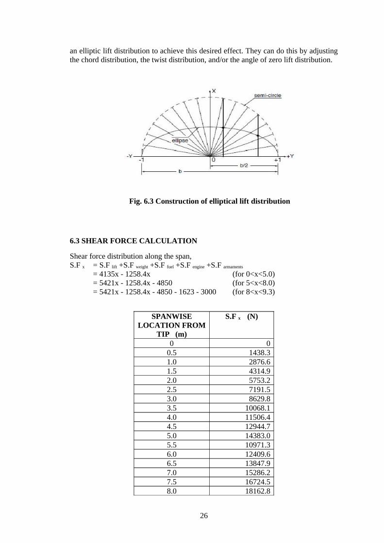
an elliptic lift distribution to achieve this desired effect. They can do this by adjusting the chord distribution, the twist distribution, and/or the angle of zero lift distribution.
Fig. 6.3 Construction of elliptical lift distribution
6.3 SHEAR FORCE CALCULATION
Shear force distribution along the span,S.F x = S.F lift +S.F weight +S.F fuel +S.F engine +S.F armaments
= 4135x - 1258.4x (for 0<x<5.0)= 5421x - 1258.4x - 4850 (for 5<x<8.0)= 5421x - 1258.4x - 4850 - 1623 - 3000 (for 8<x<9.3)
SPANWISE LOCATION FROM
TIP (m)
S.F x (N)
0 00.5 1438.31.0 2876.61.5 4314.92.0 5753.22.5 7191.53.0 8629.83.5 10068.14.0 11506.44.5 12944.75.0 14383.05.5 10971.36.0 12409.66.5 13847.97.0 15286.27.5 16724.58.0 18162.8
26

8.5 14978.19.0 16416.49.3 17279.4
6.4 SHEAR FORCE DIAGRAM
Fig. 6.4 Shear Force Diagram
6.5 BENDING MOMENT CALCULATION
Bending moment distribution along the span,B.M x = B.M lift +B.M weight +B.M fuel +B.M engine +B.M armaments
= 1033.8 x2 - 629.2x2 (for 0<x<5.0) = 1033.8 x2 - 629.2x2 - 4850(x–5) (for 5<x<8.0)
= 1033.8 x2 - 629.2x2 - 4850(x–5) – 1623 – 3000 (for 8<x<9.3)
SPANWISE LOCATION FROM
TIP (m)
B.M x (Nm)
0 00.5 101.21.0 404.61.5 910.42.0 1618.42.5 2528.83.0 3641.43.5 4956.44.0 6473.64.5 8193.2
27

5.0 10115.05.5 9814.16.0 9715.66.5 9819.47.0 10125.47.5 10633.88.0 11344.48.5 7634.49.0 8749.69.3 9515.8
6.6 BENDING MOMENT DIAGRAM
Fig. 6.5 Bending Moment Diagram
SPAR DEFINITION
We design three spars with front spar located at 15% of chord, middle spar located at 45% of chord and rear spar at 70% of chord.
Root chord = 8.19 mTherefore, position of the three spars from leading edge of root chord is calculated as:Front spar = 0.15 x 8.19 = 1.23 mMiddle spar = 0.45 x 8.19 = 3.69 mRear spar = 0.70 x 8.19 = 5.73 m
As per calculation,Maximum bending moment = 11344.4 Nm
Bending moment = Maximum BM x Factor of safety x n
28
= 11344.4 x 1.5 x 9= 153149.4 Nm
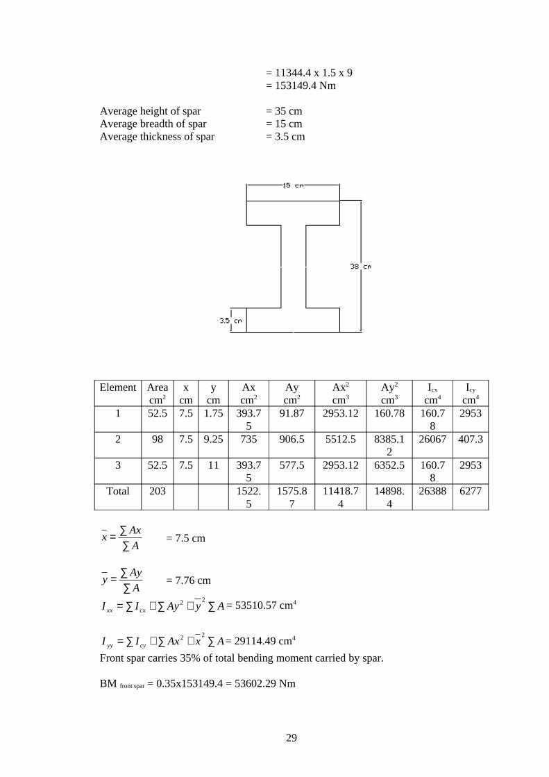
Average height of spar = 35 cmAverage breadth of spar = 15 cmAverage thickness of spar = 3.5 cm
Element Area cm2
xcm
ycm
Axcm2
Aycm2
Ax2
cm3Ay2
cm3Icx
cm4Icy
cm4
1 52.5 7.5 1.75 393.75
91.87 2953.12 160.78 160.78
2953
2 98 7.5 9.25 735 906.5 5512.5 8385.12
26067 407.3
3 52.5 7.5 11 393.75
577.5 2953.12 6352.5 160.78
2953
Total 203 1522.5
1575.87
11418.74
14898.4
26388 6277
A
Axx
∑∑= = 7.5 cm
A
Ayy
∑∑= = 7.76 cm
AyAyII cxxx ∑+∑+∑=22 = 53510.57 cm4
AxAxII cyyy ∑+∑+∑=22 = 29114.49 cm4
Front spar carries 35% of total bending moment carried by spar.
BM front spar = 0.35x153149.4 = 53602.29 Nm
29
Middle spar carries 40% of total bending moment carried by spar.
BM middle spar = 0.40x153149.4 = 61259.76 Nm
Rear spar carries 25% of total bending moment carried by spar.
BM rear spar = 0.25x153149.4 = 38287.35 Nm
7. LOAD ESTIMATON OF FUSELAGE
The design of the fuselage is based on payload requirements, aerodynamics, and structures. The overall dimensions of the fuselage affect the drag through several factors. Fuselages with smaller fineness ratios have less wetted area to enclose a given volume, but more wetted area when the diameter and length of the cabin are fixed.
The higher Reynolds number and increased tail length generally lead to improved aerodynamics for long, thin fuselages, at the expense of structural weight. Selection of the best layout requires a detailed study of these trade-offs, but to start the design process, something must be chosen. This is generally done by selecting a value not too different from existing aircraft with similar requirements, for which such a detailed study has presumably been done. In the absence of such guidance, one selects an initial layout that satisfies the payload requirements.
At supersonic speeds the shape and dimensions of the fuselage have a strong effect on the aircraft drag. Supersonic wave drag increases quickly as the fuselage volume increases and the fineness ratio is reduced. For this reason, the cabin diameter is kept as small as possible and the cabin length increased.
Longerons are used for the construction of fuselage. Hence we need to calculate the number of longerons used and the spacing between two longerons.
LONGERONS:
Longerons are used for the construction of fuselage. Hence we need to calculate the number of longerons used and the spacing between two longerons.
Calculation is as follows:Let us assume,the spacing between the longerons = 0.75m(as per standards)
Radius of the fuselage as calculated = 2.75m
Circumference of the fuselage = 17.28 m
30
No. of longerons = Spacing
nceCircumfere=
75.0
28.17 = 23
Now we decide to remove the two longerons placed at 0 & 180 degrees as, they do not have any axial stress. We get total of 21 longerons.
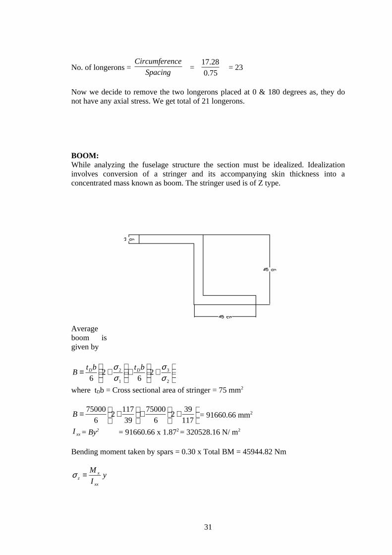
BOOM:While analyzing the fuselage structure the section must be idealized. Idealization involves conversion of a stringer and its accompanying skin thickness into a concentrated mass known as boom. The stringer used is of Z type.
Average boom is given by
++
+=
2
3
1
2 26
26 σ
σσσ btbt
B DD
where tDb = Cross sectional area of stringer = 75 mm2
++
+=
117
392
6
75000
39
1172
6
75000B = 91660.66 mm2
xxI = By2 = 91660.66 x 1.872 = 320528.16 N/ m2
Bending moment taken by spars = 0.30 x Total BM = 45944.82 Nm
yI
M
xx
xz =σ
31

y zσ N/ m2
2.4 2088.54.8 1044.37.2 696.19.6 522.112 417.7
8. BALANCING AND MANEUVERING LOADS
Balance, the proper placement of the center of gravity (c.g.) with respect to the aerodynamic center of the wing, is a vital element of a proper, and safe, flying airplane. In order to attain proper stability the c.g. must never,under any condition of fuel loading, passenger loading, cargo loading or landing gear retraction or extension, be aft of the aft stability limit. For proper control, usually trim in the landing approach configuration or nose wheel lift off, the c.g. must never be forward of the most forward aerodynamic limit.
Fig. 8.1 Balance diagram
After completing the first weight estimate of a configuration, the center of gravity of the airplane should be estimated. A moment schedule should be constructed listing each element of the airplane, its weight and the location of its center of gravity. The c.g.'s are located by their distances from two mutually perpendicular axes. These axes may be arbitrarily chosen but the horizontal axis is usually taken parallel to the fuselage floor and the vertical axis is best selected near the estimated airplane c.g. The moments of each element about the origin are then determined and the total used to establish the empty airplane c.g. If the wing is not
32

suitably located, it must be shifted forward or aft and the moment calculation readjusted. Note that relocating the wing also may move engines and landing gear as well as requiring tail size changes because the tail length (moment arm) is altered.
9. DETAILED STRUCTURAL LAYOUTS
)( yC = 2
21
4
−
b
y
b
S
π
From ADP-IS = 99.13 m2
b = 18.67 m
The chord distribution is as follows.
y m C(y)1.87 6.623.73 6.205.60 5.417.47 4.059.33 0
INLET GEOMETRY
Turbofan engines are incapable of efficient operations unless the air entering them is slowed to a speed of about Mach 0.4-0.5. This is to keep the tip speed of the compressor below sonic speed relative to the incoming air. Slowing down the incoming air is the primary purpose of an inlet system. Among many types of inlets, the 2D ramp inlet is chosen. The ramp inlet tends to be used more for speed upto Mach 2.
INLET LOCATION
As a rule of thumb, all inlet should be located a height above the runway equal to at least 80% of the inlet’s height if using a low by-pass ratio engine. This requirement increases the landing gear height.
Side-mounted inlets are virtually standard for aircraft with twin engines in the fuselage. Side inlets provide short ducts and relatively clean air. Side-mounted inlets
33
can have problems at high angles of attack due to the vortex shed off the lower corner of the forebody.
CAPTURE-AREA CALCULATION
For Mach 2, Capture-area/mass flow = 0.0055 m2/kg-s
Mass flow = 127 X engine front face diameter2
Engine front face diameter = 80% of maximum diameter = 80% of 1.25 = 1
Mass flow = 127 kg/s
Capture-area = 0.6985 m2
NOZZLE
The fundamental problem in jet engine nozzle design is the mismatch in desired exit areas at different speeds, altitudes and thrust settings. For initial design layout, reasonable approximation can be made based upon the estimated capture area. For maximum supersonic afterburning operations, the required exit area is about 1.2 to 1.6 times the capture area.
Required exit area = 1.04 m2
FUEL SYSTEM
An aircraft fuel system includes the fuel tanks, fuel lines, fuel pumps, vents and fuel management controls. Usually the tanks themselves are the only components that affect the overall aircraft layout.
From initial sizing,
Wf = 9700 kg
Density of fuel = 719 kg/m3
Volume of fuel = mass/density = 13.49m3
Fuel compartments Volume, m3 Weight, kg
Wing 6 4314
Fuselage 7 5033
34

Tail 0.49 353
Total 13.49 9700
LANDING GEAR
Weight acting on individual main gear
Ww = 0.9 X W0/2
= 14143.5 kg
Wheel diameter and width = AWwB
Main wheel
dm = 5.1 X 14143.50.302
= 91.42 cm
= 0.91 m.
Wm = 0.36 X 14143.50.467
= 31.23 cm
= 0.31 m.
Nose wheel
dn = dm X 0.8
= 0.73 m
wn = Wm X 0.8
= 0.25 m
35

10. DESIGN OF SOME COMPONENTS OF WINGS ANDFUSELAGE
10.1 PONTOON
The amphibious fighter is has pontoon with V-shaped bottom to reduce the water impact loads. The height of the V is called the deadrise, and the angle is the deadrise angle. Deadrise angle must be increased for higher landing speeds and it is increased toward the nose to about 30-40 deg to better cut through waves.
deadriseα = 102
−V ,deg
where V = stall speed in miles per hour
deadriseα = 102
85.111 −
= 45.92 deg
To reduce water spray, spray strips can be attached to the edges of the bottom. These are angled about 30 deg below the horizon.
10.2 TAIL
Vertical tail area is given by
VTS = VT
wwVT
L
Sbc
Horizontal tail area is given by
36

HTS = HT
wwHT
L
SCc
where VTc = Vertical tail volume coefficient = 0.07 (typical for fighter)
HTc = Horizontal tail volume coefficient = 0.40 (typical for fighter)
wb = Wing span
wC = Wing mean chord = 5.32 m
L = Moment arm(Distance from tail quarter-chord to wing quarter-chord)
VTS = 33.1
13.9933.907.0 ××= 48.67 m2
HTS = 187.0
13.9932.540.0 ×× = 39.47 m2
The aircraft uses a V-tail and the tail dihedral angle is set to the arctangent of the square root of the ratio between the horizontal and vertical tail areas.
Tail dihedral angle =
−
HT
VT
S
S1tan
=
−
47.39
67.48tan 1
= 47.99 deg
10.3 CONTROL SURFACE
Control surfaces are usually tapered in chord by the same ratio as the wing or tail surface so that the control surface remains a constant percent chord. This allows the spars to be straight-tapered rather than curved.
The ailerons typically extend from about 50% to about 90% of the span. Therefore, it extends from 4.67 m to 8.39 m along the span. Ailerons and flaps are typically 15-25% of wing chord along the span.
FUSELAGE
The fuselage includes the cabin and/or cockpit, which contains seats for the occupants and the controls for the airplane. In addition, the fuselage may also provide room for cargo and attachment points for the other major airplane components. Some aircraft
37
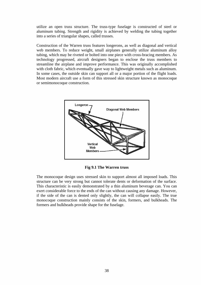
utilize an open truss structure. The truss-type fuselage is constructed of steel or aluminum tubing. Strength and rigidity is achieved by welding the tubing together into a series of triangular shapes, called trusses.
Construction of the Warren truss features longerons, as well as diagonal and vertical web members. To reduce weight, small airplanes generally utilize aluminum alloy tubing, which may be riveted or bolted into one piece with cross-bracing members. As technology progressed, aircraft designers began to enclose the truss members to streamline the airplane and improve performance. This was originally accomplished with cloth fabric, which eventually gave way to lightweight metals such as aluminum. In some cases, the outside skin can support all or a major portion of the flight loads. Most modern aircraft use a form of this stressed skin structure known as monocoque or semimonocoque construction.
Fig 9.1 The Warren truss
The monocoque design uses stressed skin to support almost all imposed loads. This structure can be very strong but cannot tolerate dents or deformation of the surface. This characteristic is easily demonstrated by a thin aluminum beverage can. You can exert considerable force to the ends of the can without causing any damage. However, if the side of the can is dented only slightly, the can will collapse easily. The true monocoque construction mainly consists of the skin, formers, and bulkheads. The formers and bulkheads provide shape for the fuselage.
38

Fig 9.2 Monocoque fuselage design.
Since no bracing members are present, the skin must be strong enough to keep the fuselage rigid. Thus, a significant problem involved in monocoque construction is maintaining enough strength while keeping the weight within allowable limits. Due to the limitations of the monocoque design, a semi-monocoque structure is used on many of today´s aircraft.
Fig. 9.3 Semi-monocoque Construction
The semi-monocoque system uses a substructure to which the airplane´s skin is attached. The substructure, which consists of bulkheads and/or formers of various sizes and stringers, reinforces the stressed skin by taking some of the bending stress from the fuselage.
WINGS
The principal structural parts of the wing are spars, ribs, and stringers.
39

Fig9.4 Wing components
These are reinforced by trusses, I-beams, tubing, or other devices, including the skin. The wing ribs determine the shape and thickness of the wing (airfoil). In most modern airplanes, the fuel tanks either are an integral part of the wing´s structure, or consist of flexible containers mounted inside of the wing. Attached to the rear, or trailing, edges of the wings are two types of control surfaces referred to as ailerons and flaps. Ailerons extend from about the midpoint of each wing outward toward the tip and move in opposite directions to create aerodynamic forces that cause the airplane to roll. Flaps extend outward from the fuselage to near the midpoint of each wing. The flaps are normally flush with the wing´s surface during cruising flight. When extended, the flaps move simultaneously downward to increase the lifting force of the wing for takeoffs and landings.
TAIL
Tail surfaces are used to both stabilize the aircraft and provide control moments needed for maneuver and trim. Because these surfaces add wetted area and structural weight they are often sized to be as small as possible.
A large variety of tail shapes have been employed on aircraft over the past century. These include configurations often denoted by the letters whose shapes they resemble in front view: T, V, H, Y, inverted V. V-tails combine functions of horizontal and vertical tails. They are sometimes chosen because of their increased ground clearance, reduced number of surface intersections, or novel look, but require mixing of rudder and elevator controls and often exhibit reduced control authority in combined yaw and pitch maneuvers.
WING LOCATION ON THE FUSELAGE
The wing position on the fuselage is set by stability and control considerations and requires a detailed weight breakdown and c.g. estimation. At the early stages of the design process one may locate the aerodynamic of the wing at the center of constant
40

section or, for aircraft with aft-fuselage-mounted engines, at 60% of constant section. (As a first estimate, one may take the aerodynamic center to be at the quarter chord of the wing at the location for which the local chord is equal to the mean aerodynamic chord.)
The lateral position of the landing gear is determined based on roll-over requirements: one must be able to withstand certain lateral accelerations without falling over. The detailed computation requires knowledge of landing gear length, fuselage mass distribution, and ground maneuver requirements. For our purposes, it is sufficient to assume that the main gear wheel track is about 1.6 fuselage diameters. For general aviation aircraft or commuters with gear attached to turbo-prop nacelles, the value is usually much larger.
It is desirable to mount the main landing gear struts on the wing spar (usually an aft spar) where the structure is substantial. However, the gear must be mounted so that at aft c.g. there is sufficient weight on the nose wheel for good steering. This generally means gear near the 50% point of the M.A.C. For wings with high sweep, high aspect ratio, or high taper ratio, the aft spar may occur forward of this point. In this case a chord extension must be added. The drawing here shows the gear mounted on a secondary spar attached to the rear spar and the addition of a chord extension to accommodate it.
HIGH LIFT SYSTEMS
A wing designed for efficient high-speed flight is often quite different from one designed solely for take-off and landing. Take-off and landing distances are strongly influenced by aircraft stalling speed, with lower stall speeds requiring lower acceleration or deceleration and correspondingly shorter field lengths. It is always possible to reduce stall speed by increasing wing area, but it is not desirable to cruise with hundreds of square feet of extra wing area (and the associated weight and drag), area that is only needed for a few minutes. Since the stalling speed is related to wing parameters by:
It is also possible to reduce stalling speed by reducing weight, increasing air density, or increasing wing CLmax . The latter parameter is the most interesting. One can design a wing airfoil that compromises cruise efficiency to obtain a good CLmax , but it is usually more efficient to include movable leading and/or trailing edges so that one may obtain good high speed performance while achieving a high CLmax at take-off and landing. The primary goal of a high lift system is a high CLmax; however, it may also be desirable to maintain low drag at take-off, or high drag on approach. It is also necessary to do this with a system that has low weight and high reliability.
FLAP GEOMETRY
41

Fig 10.1. Flap System Geometries
The figure below shows a double-slotted flap and slat system (a 4-element airfoil). Here, some of the increase in CLmax is associated with an increase in chord length (Fowler motion) provided by motion along the flap track or by a rotation axis that is located below the wing.
Fig 10.2 Double-Slotted Flap and Slat System
42
11. DETAILED DESIGN REPORT WITH DRAWINGS
11.1 SPECIFICATIONS
Length = 24.80 m
Span = 18.67 m
Height = 8.77 m
Root chord = 8.19 m
Tip chord = 2.45 m
Mean chord = 5.32 m
Planform area = 99.13 m2
Aspect ratio = 3.52
Taper ratio = 0.3
Leading edge sweep = 55 (deg)
Empty weight = 15730 kg
Total takeoff weight = 31430 kg
Fuel weight = 9700 kg
43

t/c = 0.04
Tail dihedral angle = 47.99 (deg)
deadriseα = 45.92 (deg)
Nozzle exit area = 1.04 m2
Engine model: 2 X Saturn/Lyulka AL-31 FM, Turbofan
Airfoil : NASA SC (2) – 0412
11.2 THREE VIEW DRAWING
44

11.3 THREE DIMENSIONAL DRAWING
45

12. REFERENCES
1. Raymer, D.P., “Aircraft Design: A Conceptual Approach, Third Edition”, AIAA, Inc., Reston, VA, pp. 229-270, 379-401, 406, 408-412, 426-446, 2006.
2. Lloyd R. Jenkinson and James F. Marchman III, “Aircraft Design Projects for engineering students”, 2003.
3. Anderson,J.D.,Jr.,” Aircraft Performance and Design”, McGraw-Hill, New York,1999.
4. The “Retractable Floats after Retractable Gears” located at http://www.seaplaneinternational.com/2010/04/14/retractable-floats-after-retractable-gears/
5. The “Airfoil Investigation Database” located at http://www.worldofkrauss.com/foils/
6.Aircraft Design: Synthesis and Analysis at http://adg.stanford.edu/aa241/AircraftDesign.html
46

47
Related Documents


![B. tech.(mechanical engineering) part iii(semester v & vi)[batch 2011]](https://static.cupdf.com/doc/110x72/55ab53b51a28ab1c208b4823/b-techmechanical-engineering-part-iiisemester-v-vibatch-2011.jpg)


![Vidya Harikrishnan 2017-18 [III batch PGDLT] · Vidya Harikrishnan 2017-18 [III batch – PGDLT] TABLE of CONTENTS Section A My Personal journey as a learner: Page 3 My Educational](https://static.cupdf.com/doc/110x72/5ede1152ad6a402d6669579d/vidya-harikrishnan-2017-18-iii-batch-pgdlt-vidya-harikrishnan-2017-18-iii-batch.jpg)