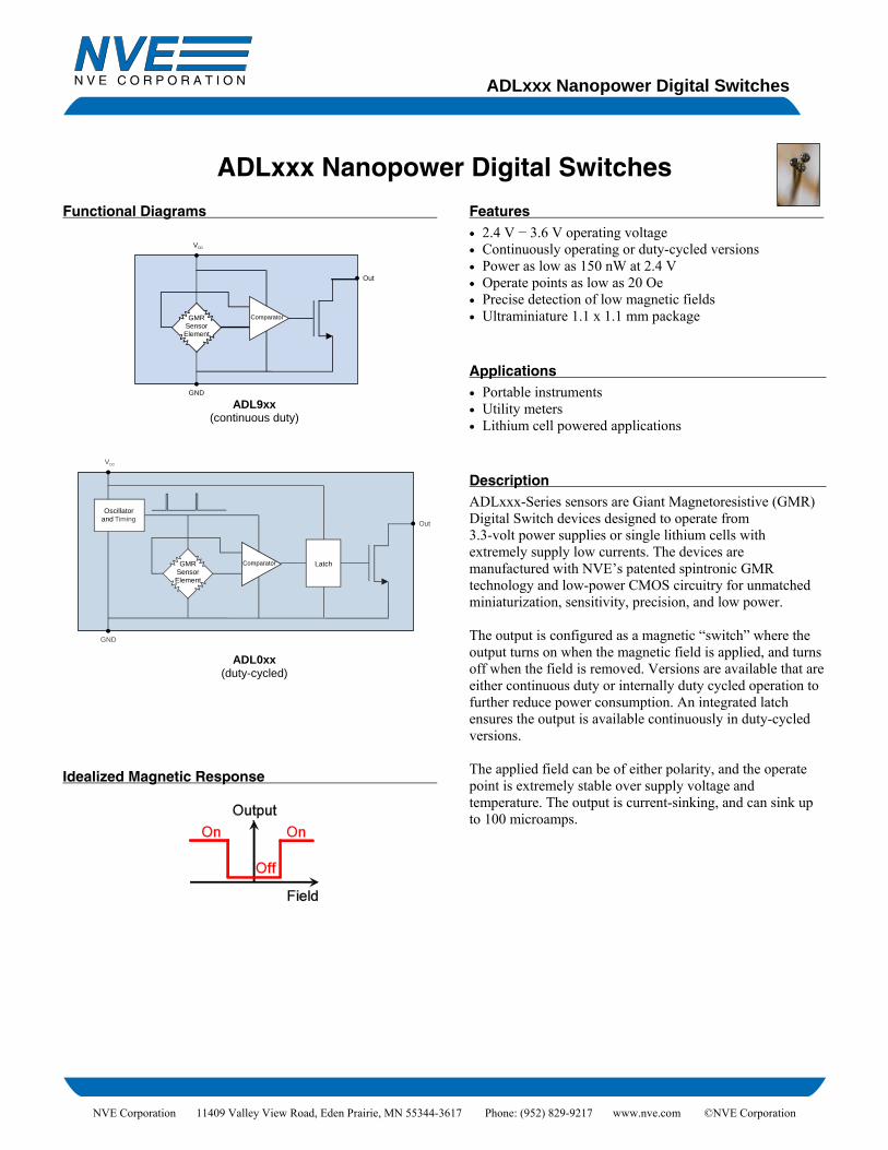
ADLxxx Nanopower Digital Switches NVE Corporation 11409 Valley View Road, Eden Prairie, MN 55344-3617 Phone: (952) 829-9217 www.nve.com ©NVE Corporation ADLxxx Nanopower Digital Switches Functional Diagrams DD GMR Sensor Element Out V Comparator GND ADL9xx (continuous duty) GMR Sensor Element Latch Out VDD Oscillator and Timing GND Comparator ADL0xx (duty-cycled) Idealized Magnetic Response Features • 2.4 V − 3.6 V operating voltage • Continuously operating or duty-cycled versions • Power as low as 150 nW at 2.4 V • Operate points as low as 20 Oe • Precise detection of low magnetic fields • Ultraminiature 1.1 x 1.1 mm package Applications • Portable instruments • Utility meters • Lithium cell powered applications Description ADLxxx-Series sensors are Giant Magnetoresistive (GMR) Digital Switch devices designed to operate from 3.3-volt power supplies or single lithium cells with extremely supply low currents. The devices are manufactured with NVE’s patented spintronic GMR technology and low-power CMOS circuitry for unmatched miniaturization, sensitivity, precision, and low power. The output is configured as a magnetic “switch” where the output turns on when the magnetic field is applied, and turns off when the field is removed. Versions are available that are either continuous duty or internally duty cycled operation to further reduce power consumption. An integrated latch ensures the output is available continuously in duty-cycled versions. The applied field can be of either polarity, and the operate point is extremely stable over supply voltage and temperature. The output is current-sinking, and can sink up to 100 microamps.

Welcome message from author
This document is posted to help you gain knowledge. Please leave a comment to let me know what you think about it! Share it to your friends and learn new things together.
Transcript
ADLxxx Nanopower Digital Switches
NVE Corporation 11409 Valley View Road, Eden Prairie, MN 55344-3617 Phone: (952) 829-9217 www.nve.com ©NVE Corporation
ADLxxx Nanopower Digital Switches Functional Diagrams
DD
GMRSensorElement
Out
V
Comparator
GND ADL9xx
(continuous duty)
GMRSensorElement
Latch
Out
VDD
Oscillatorand Timing
GND
Comparator
ADL0xx
(duty-cycled)
Idealized Magnetic Response
Features • 2.4 V − 3.6 V operating voltage • Continuously operating or duty-cycled versions • Power as low as 150 nW at 2.4 V • Operate points as low as 20 Oe • Precise detection of low magnetic fields • Ultraminiature 1.1 x 1.1 mm package
Applications• Portable instruments • Utility meters • Lithium cell powered applications
DescriptionADLxxx-Series sensors are Giant Magnetoresistive (GMR) Digital Switch devices designed to operate from 3.3-volt power supplies or single lithium cells with extremely supply low currents. The devices are manufactured with NVE’s patented spintronic GMR technology and low-power CMOS circuitry for unmatched miniaturization, sensitivity, precision, and low power. The output is configured as a magnetic “switch” where the output turns on when the magnetic field is applied, and turns off when the field is removed. Versions are available that are either continuous duty or internally duty cycled operation to further reduce power consumption. An integrated latch ensures the output is available continuously in duty-cycled versions. The applied field can be of either polarity, and the operate point is extremely stable over supply voltage and temperature. The output is current-sinking, and can sink up to 100 microamps.
ADLxxx Nanopower Digital Switches
2
NVE Corporation 11409 Valley View Road, Eden Prairie, MN 55344-3617 Phone: (952) 829-9217 www.nve.com ©NVE Corporation
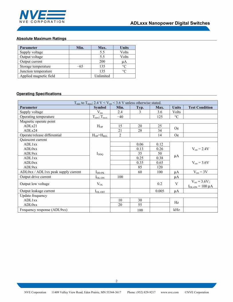
Absolute Maximum Ratings
Parameter Min. Max. Units Supply voltage 5.5 Volts Output voltage 5.5 Volts Output current 200 μA Storage temperature −65 135 °C Junction temperature 135 °C Applied magnetic field Unlimited
Operating Specifications
Tmin to Tmax; 2.4 V < VDD < 3.6 V unless otherwise stated. Parameter Symbol Min. Typ. Max. Units Test Condition Supply voltage VDD 2.4 3 3.6 Volts Operating temperature TMIN; TMAX −40 125 °C Magnetic operate point
HOP
ADLx21 15 20 25 Oe ADLx24 21 28 34 Operate/release differential HOP−HREL 2 14 Oe Quiescent current
IDDQ
ADL1xx 0.06 0.12
μA
VDD = 2.4V ADL0xx 0.13 0.26 ADL9xx 35 50 ADL1xx 0.25 0.38
VDD = 3.6V ADL0xx 0.35 0.65 ADL9xx 85 120 ADL0xx / ADL1xx peak supply current IDD-PK 60 100 μA VDD = 3V Output drive current IOL-ON 100 μA
Output low voltage VOL 0.2 V VDD = 3.6V; IOL-ON = 100 μA
Output leakage current IOL-OFF 0.005 μA Update frequency
ADL1xx 10 30 Hz ADL0xx 20 55 Frequency response (ADL9xx) 100 kHz
ADLxxx Nanopower Digital Switches
3
NVE Corporation 11409 Valley View Road, Eden Prairie, MN 55344-3617 Phone: (952) 829-9217 www.nve.com ©NVE Corporation
Operation Direction of Magnetic Sensitivity As the field varies in intensity, the digital output will turn on and off. Unlike Hall effect or other sensors, the direction of sensitivity is in the plane of the package. The diagrams below show two permanent magnet orientations that will activate the sensor in the direction of sensitivity:
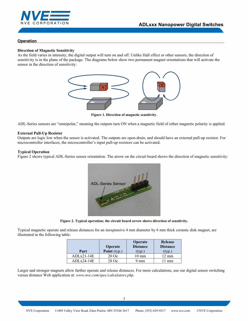
Figure 1. Direction of magnetic sensitivity. ADL-Series sensors are “omnipolar,” meaning the outputs turn ON when a magnetic field of either magnetic polarity is applied. External Pull-Up Resistor Outputs are logic low when the sensor is activated. The outputs are open-drain, and should have an external pull-up resistor. For microcontroller interfaces, the microcontroller’s input pull-up resistors can be activated. Typical Operation Figure 2 shows typical ADL-Series sensor orientation. The arrow on the circuit board shows the direction of magnetic sensitivity:
Figure 2. Typical operation; the circuit board arrow shows direction of sensitivity. Typical magnetic operate and release distances for an inexpensive 4 mm diameter by 6 mm thick ceramic disk magnet, are illustrated in the following table:
Part Operate
Point (typ.)
Operate Distance
(typ.)
Release Distance
(typ.) ADLx21-14E 20 Oe 10 mm 12 mm ADLx24-14E 28 Oe 9 mm 11 mm
Larger and stronger magnets allow farther operate and release distances. For more calculations, use our digital sensor switching versus distance Web application at: www.nve.com/spec/calculators.php.
ADL-Series Sensor
ADLxxx Nanopower Digital Switches
4
NVE Corporation 11409 Valley View Road, Eden Prairie, MN 55344-3617 Phone: (952) 829-9217 www.nve.com ©NVE Corporation
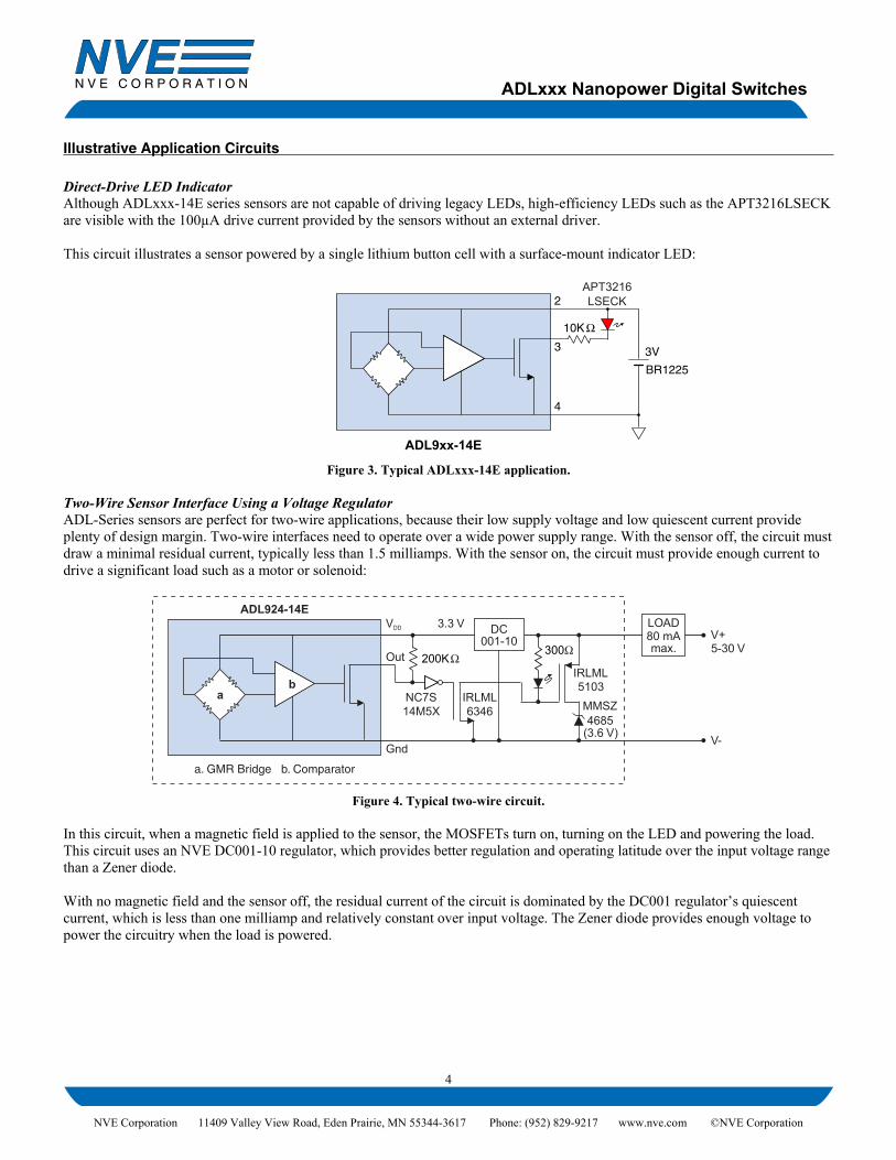
Illustrative Application Circuits Direct-Drive LED Indicator Although ADLxxx-14E series sensors are not capable of driving legacy LEDs, high-efficiency LEDs such as the APT3216LSECK are visible with the 100µA drive current provided by the sensors without an external driver. This circuit illustrates a sensor powered by a single lithium button cell with a surface-mount indicator LED:
ADL9xx-14E
10K
BR1225
3V
2
3
4
APT3216LSECK
Figure 3. Typical ADLxxx-14E application. Two-Wire Sensor Interface Using a Voltage Regulator ADL-Series sensors are perfect for two-wire applications, because their low supply voltage and low quiescent current provide plenty of design margin. Two-wire interfaces need to operate over a wide power supply range. With the sensor off, the circuit must draw a minimal residual current, typically less than 1.5 milliamps. With the sensor on, the circuit must provide enough current to drive a significant load such as a motor or solenoid:
a. GMR Bridge b. Comparator
ADL924-14E
a
Out
VDD
Gnd
b
V+LOAD
300
IRLML
V-
200K
NC7S14M5X
5103IRLML6346
5-30 V80 mAmax.
DC3.3 V
MMSZ
(3.6 V)4685
001-10
Figure 4. Typical two-wire circuit.
In this circuit, when a magnetic field is applied to the sensor, the MOSFETs turn on, turning on the LED and powering the load. This circuit uses an NVE DC001-10 regulator, which provides better regulation and operating latitude over the input voltage range than a Zener diode. With no magnetic field and the sensor off, the residual current of the circuit is dominated by the DC001 regulator’s quiescent current, which is less than one milliamp and relatively constant over input voltage. The Zener diode provides enough voltage to power the circuitry when the load is powered.
ADLxxx Nanopower Digital Switches
NVE Corporation 11409 Valley View Road, Eden Prairie, MN 55344-3617 Phone: (952) 829-9217 www.nve.com ©NVE Corporation
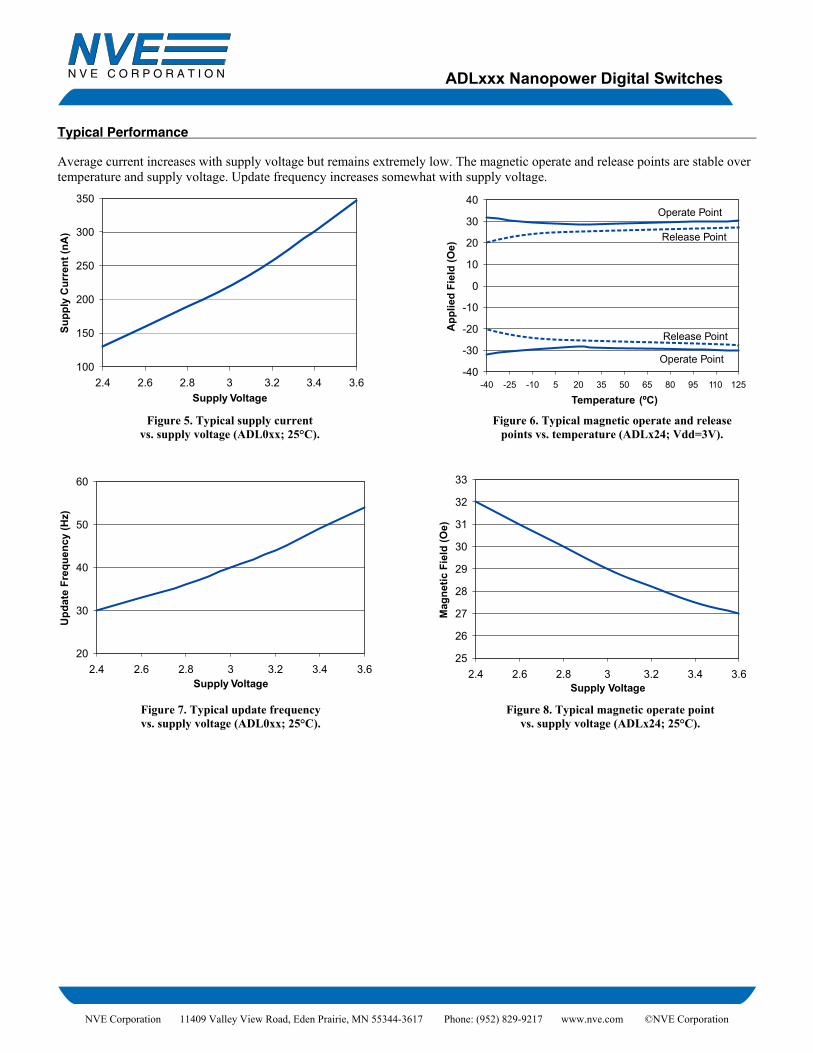
Typical Performance Average current increases with supply voltage but remains extremely low. The magnetic operate and release points are stable over temperature and supply voltage. Update frequency increases somewhat with supply voltage.
100
150
200
250
300
350
2.4 2.6 2.8 3 3.2 3.4 3.6Supply Voltage
Supp
ly C
urre
nt (n
A)
20
30
40
50
60
2.4 2.6 2.8 3 3.2 3.4 3.6Supply Voltage
Upd
ate
Freq
uenc
y (H
z)
-40
-30
-20
-10
0
10
20
30
40
-40 -25 -10 5 20 35 50 65 80 95 110 125
Temperature (ºC)
App
lied
Fiel
d (O
e)
Operate Point
Release Point
Release Point
Operate Point
25
26
27
28
29
30
31
32
33
2.4 2.6 2.8 3 3.2 3.4 3.6Supply Voltage
Mag
netic
Fie
ld (O
e)
Figure 5. Typical supply current vs. supply voltage (ADL0xx; 25°C).
Figure 6. Typical magnetic operate and release points vs. temperature (ADLx24; Vdd=3V).
Figure 7. Typical update frequency vs. supply voltage (ADL0xx; 25°C).
Figure 8. Typical magnetic operate point vs. supply voltage (ADLx24; 25°C).
ADLxxx Nanopower Digital Switches
6
NVE Corporation 11409 Valley View Road, Eden Prairie, MN 55344-3617 Phone: (952) 829-9217 www.nve.com ©NVE Corporation
Part Numbering
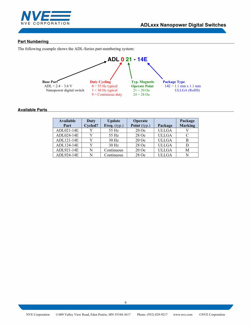
The following example shows the ADL-Series part-numbering system:
ADL 0 21 - 14E
Base Part ADL = 2.4 – 3.6 V Nanopower digital switch
Duty Cycling 0 = 55 Hz typical 1 = 30 Hz typical 9 = Continuous duty
Typ. Magnetic Operate Point 21 = 20 Oe 24 = 28 Oe
Package Type 14E = 1.1 mm x 1.1 mm ULLGA (RoHS)
Available Parts
Available Part
Duty Cycled?
Update Freq. (typ.)
Operate Point (typ.) Package
Package Marking
ADL021-14E Y 55 Hz 20 Oe ULLGA V ADL024-14E Y 55 Hz 28 Oe ULLGA C ADL121-14E Y 30 Hz 20 Oe ULLGA B ADL124-14E Y 30 Hz 28 Oe ULLGA D ADL921-14E N Continuous 20 Oe ULLGA M ADL924-14E N Continuous 28 Oe ULLGA N

ADLxxx Nanopower Digital Switches
7
NVE Corporation 11409 Valley View Road, Eden Prairie, MN 55344-3617 Phone: (952) 829-9217 www.nve.com ©NVE Corporation
Evaluation Kits NVE offers two ADL-Series Demonstration Boards, one with a battery and one without. These inexpensive evaluation kits include demo boards with the ultraminiature, ultralow-power ADL021 magnetic switch included. An LED shows the sensor output. A miniature bar magnet is included so you can see for yourself how these remarkable sensors work. These miniature evaluation boards are just 1.57 by 0.25 inches (40 x 6 mm). Images are actual size:
www.nve.com AG040-06
LED
GN
D
VD
D
OU
T
R1R2C
AG040C: ADL021 Externally-Powered Evaluation Board This board has a digital output, and can be powered from a 3.3-volt nominal supply. An LED shows the output.
www.nve.com AG040-06
LEDR2
GN
D
VD
D
OU
T
R1
AG040B: ADL021 Battery-Powered Demonstration Board This board is powered by a three-volt lithium coin cell (included), and the sensor quiescent power consumption is so low that the battery will last indefinitely.
Bare Circuit Boards NVE offers two bare circuit boards designed for easy connections to ULLGA sensors. Note that since these boards use very small sensors, they require reflow or hot-air soldering techniques. Images are actual size:
AG904-06: ULLGA General-Purpose PCB 1.2 x 0.25 inch (30 x 6 mm) PCB for demonstrating 1.1 x 1.1 mm ULLGA4 sensors (-14E sensor suffix).
www.nve.com AG039-06
GN
D
VCC
OU
T
C1 R
AG039-06: ULLGA Digital Sensor Demonstration Bare Board A 1.57 x 0.25 inch PCB for demonstrating ADL-Series sensors (sensors sold separately). In addition to space for the sensor, the boards have locations for 0402-size pull-up resistors and bypass capacitors.
ADLxxx Nanopower Digital Switches
8
NVE Corporation 11409 Valley View Road, Eden Prairie, MN 55344-3617 Phone: (952) 829-9217 www.nve.com ©NVE Corporation
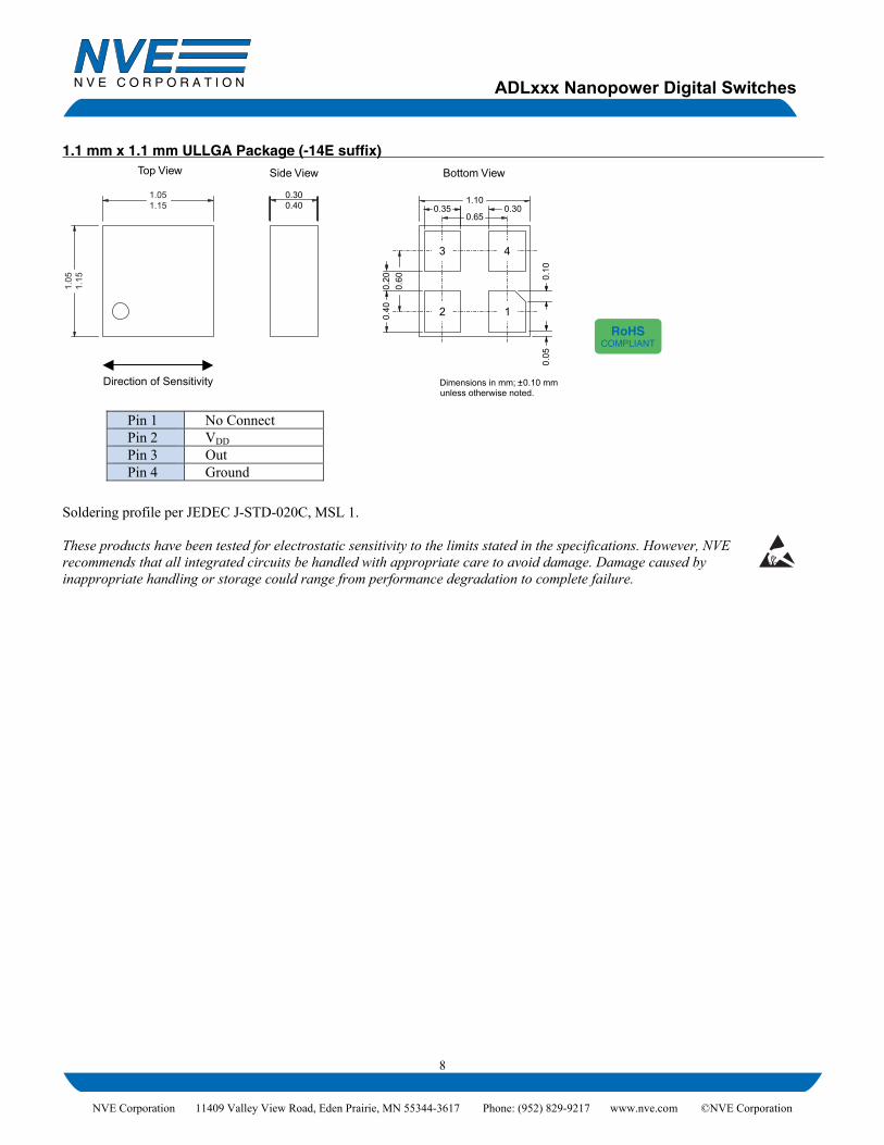
1.1 mm x 1.1 mm ULLGA Package (-14E suffix) Bottom View
1.100.35
0.65
0.40
0.60
0.05
0.10
0.30
12
3 4
0.30
Side View
0.20
Top View
Dimensions in mm; ±�0.10 mmDirection of Sensitivity
0.40
unless otherwise noted.
1.051.15
1.05
1.15
Soldering profile per JEDEC J-STD-020C, MSL 1. These products have been tested for electrostatic sensitivity to the limits stated in the specifications. However, NVE recommends that all integrated circuits be handled with appropriate care to avoid damage. Damage caused by inappropriate handling or storage could range from performance degradation to complete failure.
Pin 1 No Connect Pin 2 VDD Pin 3 Out Pin 4 Ground
RoHSCOMPLIANT

ADLxxx Nanopower Digital Switches
9
NVE Corporation 11409 Valley View Road, Eden Prairie, MN 55344-3617 Phone: (952) 829-9217 www.nve.com ©NVE Corporation
Revision History
SB-00-017 November 2017
Change • Added “Typical Operation” section and image (p. 3). • Added Evaluation Kits and bare boards (p. 7).
SB-00-017 October 2017
Change • Revised package outline dimensions.
SB-00-017 May 2017
Changes • Added application circuit. • Revised quiescent current specifications. • Added selector guide. • Obsoleted ADLx22 versions/ • Cosmetic changes.
SB-00-017 December 2008
Change • Initial Release.
ADLxxx Nanopower Digital Switches
10
NVE Corporation 11409 Valley View Road, Eden Prairie, MN 55344-3617 Phone: (952) 829-9217 www.nve.com ©NVE Corporation
Datasheet Limitations The information and data provided in datasheets shall define the specification of the product as agreed between NVE and its customer, unless NVE and customer have explicitly agreed otherwise in writing. All specifications are based on NVE test protocols. In no event however, shall an agreement be valid in which the NVE product is deemed to offer functions and qualities beyond those described in the datasheet. Limited Warranty and Liability Information in this document is believed to be accurate and reliable. However, NVE does not give any representations or warranties, expressed or implied, as to the accuracy or completeness of such information and shall have no liability for the consequences of use of such information. In no event shall NVE be liable for any indirect, incidental, punitive, special or consequential damages (including, without limitation, lost profits, lost savings, business interruption, costs related to the removal or replacement of any products or rework charges) whether or not such damages are based on tort (including negligence), warranty, breach of contract or any other legal theory. Right to Make Changes NVE reserves the right to make changes to information published in this document including, without limitation, specifications and product descriptions at any time and without notice. This document supersedes and replaces all information supplied prior to its publication. Use in Life-Critical or Safety-Critical Applications Unless NVE and a customer explicitly agree otherwise in writing, NVE products are not designed, authorized or warranted to be suitable for use in life support, life-critical or safety-critical devices or equipment. NVE accepts no liability for inclusion or use of NVE products in such applications and such inclusion or use is at the customer’s own risk. Should the customer use NVE products for such application whether authorized by NVE or not, the customer shall indemnify and hold NVE harmless against all claims and damages. Applications Applications described in this datasheet are illustrative only. NVE makes no representation or warranty that such applications will be suitable for the specified use without further testing or modification. Customers are responsible for the design and operation of their applications and products using NVE products, and NVE accepts no liability for any assistance with applications or customer product design. It is customer’s sole responsibility to determine whether the NVE product is suitable and fit for the customer’s applications and products planned, as well as for the planned application and use of customer’s third party customers. Customers should provide appropriate design and operating safeguards to minimize the risks associated with their applications and products. NVE does not accept any liability related to any default, damage, costs or problem which is based on any weakness or default in the customer’s applications or products, or the application or use by customer’s third party customers. The customer is responsible for all necessary testing for the customer’s applications and products using NVE products in order to avoid a default of the applications and the products or of the application or use by customer’s third party customers. NVE accepts no liability in this respect. Limiting Values Stress above one or more limiting values (as defined in the Absolute Maximum Ratings System of IEC 60134) will cause permanent damage to the device. Limiting values are stress ratings only and operation of the device at these or any other conditions above those given in the recommended operating conditions of the datasheet is not warranted. Constant or repeated exposure to limiting values will permanently and irreversibly affect the quality and reliability of the device. Terms and Conditions of Sale In case an individual agreement is concluded only the terms and conditions of the respective agreement shall apply. NVE hereby expressly objects to applying the customer’s general terms and conditions with regard to the purchase of NVE products by customer. No Offer to Sell or License Nothing in this document may be interpreted or construed as an offer to sell products that is open for acceptance or the grant, conveyance or implication of any license under any copyrights, patents or other industrial or intellectual property rights. Export Control This document as well as the items described herein may be subject to export control regulations. Export might require a prior authorization from national authorities. Automotive Qualified Products Unless the datasheet expressly states that a specific NVE product is automotive qualified, the product is not suitable for automotive use. It is neither qualified nor tested in accordance with automotive testing or application requirements. NVE accepts no liability for inclusion or use of non-automotive qualified products in automotive equipment or applications. In the event that customer uses the product for design-in and use in automotive applications to automotive specifications and standards, customer (a) shall use the product without NVE’s warranty of the product for such automotive applications, use and specifications, and (b) whenever customer uses the product for automotive applications beyond NVE’s specifications such use shall be solely at customer’s own risk, and (c) customer fully indemnifies NVE for any liability, damages or failed product claims resulting from customer design and use of the product for automotive applications beyond NVE’s standard warranty and NVE’s product specifications.
ADLxxx Nanopower Digital Switches
11
NVE Corporation 11409 Valley View Road, Eden Prairie, MN 55344-3617 Phone: (952) 829-9217 www.nve.com ©NVE Corporation
An ISO 9001 Certified Company NVE Corporation 11409 Valley View Road Eden Prairie, MN 55344-3617 USA Telephone: (952) 829-9217 www.nve.com e-mail: [email protected] ©NVE Corporation All rights are reserved. Reproduction in whole or in part is prohibited without the prior written consent of the copyright owner. SB-00-017
rev. Nov. 2017
Related Documents