1 EXAMENSARBETE INOM TEKNIKOMRÅDET, TEKNISK KEMI OCH HUVUDOMRÅDET KEMITEKNIK, AVANCERAD NIVÅ, 30 HP STOCKHOLM, SVERIGE 2019 Adhesive Performance of UV- cured Clearcoat on Galvanized Steel KHANH TRINH KTH SKOLAN FÖR KEMI, BIOTEKNOLOGI OCH HÄLSA

Welcome message from author
This document is posted to help you gain knowledge. Please leave a comment to let me know what you think about it! Share it to your friends and learn new things together.
Transcript

1
EXAMENSARBETE INOM TEKNIKOMRÅDET,
TEKNISK KEMI
OCH HUVUDOMRÅDET
KEMITEKNIK,
AVANCERAD NIVÅ, 30 HP
STOCKHOLM, SVERIGE 2019
Adhesive Performance of UV-cured Clearcoat on Galvanized Steel
KHANH TRINH
KTH
SKOLAN FÖR KEMI, BIOTEKNOLOGI OCH HÄLSA

Adhesive Performance of UV-cured
Clearcoat on Galvanized Steel
Khanh Trinh
EXAMENSARBETE INOM TEKNIK KEMI PROGRAMMET CIVILINGENJÖR Titel på engelska: Adhesive Perfomance of UV-cured Clearcoat on Galvanized Steel. Huvudhandledare: Per-Erik Sundell. Företag: SSAB Tunnplåt AB Sverige. Examinator: Mats Johansson, KTH Royal Institute of Technology. Datum: 2019-07-03

ABSTRACT
A study has been carried out regarding the possibility for application of UV-cured coatings on
different pretreated galvanized steel, in coil coating application. In order to address the
questions about whether the adhesion will be affected and how, when combining respective
coating with a steel substrate. Two types of UV-curable formulations have been applied
respectively, acrylate-based free radical formulation and epoxy-based cationic formulation, on
five types of steel substrates. In addition, UV-LED was also investigated as an alternative
energy source.
The aim is to explore the curing of the coatings, the surface topology and hydrophilicity, the
material and mechanical properties of coatings and coated systems respectively. It was found
that the acrylate coating gives a hydrophilic surface while the epoxy coat is hydrophilic but is
more hydrophobic than acrylate. The acrylate resin is not compatible with Standard Ti-
pretreatment from PO substrates and the curing of epoxy is inhibited by pretreatment primer in
PP substrates. Curing using UV-LED is possible and should be investigated further. No
comparison could be made between coating systems acrylate and epoxy, regarding the adhesive
performance, due to the failure of obtaining the right thickness for the acrylate coating.
SAMMANFATTNING
I denna studie undersöktes möjligheten att applicera UV-härdande lacker på olika
förbehandlade galvaniserade stålsorter för bandlackering. Detta för att förstå mer om
vidhäftningen påverkas av, och på vilket sätt, kombinationen av respektive UV-lack med olika
metallsubstrat. Två olika UV-formuleringar, akrylat and epoxy, applicerades på fem olika
stålsubtrat och även screeningsstudie på UV-LED utfördes.
Målet är att undersöka uthärdning av lackeringar, topologin och hydrofilicitet, material och
mekaniska egenskaper hos färglacken och de lackade systemen, samt möjlighet att använda
LED-lampa som UV-källan. Resultatet visar att akrylat ger en hydrofil yta medan epoxy är
hydrofil men är mer hydrofob än akrylat. Akrylatet är inte kompatibelt med Standard Ti-
pretreatment från PO substrat och uthärdning av epoxy inhiberas av förbehandlade primer på
PP-prover. Uthärdning med UV-LED är möjligt och bör undersökas ytterligare. Det gick inte
att jämföra mellan de två UV-formuleringarna, akrylat och epoxy, på grund av fel tjocklek hos
akrylat- filmerna.
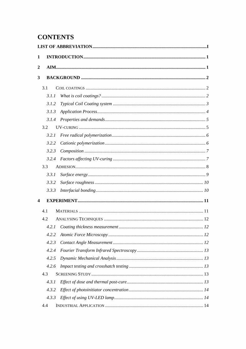
CONTENTS
LIST OF ABBREVIATION .................................................................................................... I
1 INTRODUCTION ........................................................................................................... 1
2 AIM................................................................................................................................... 1
3 BACKGROUND ............................................................................................................. 2
3.1 COIL COATINGS ......................................................................................................... 2
3.1.1 What is coil coatings? ........................................................................................... 2
3.1.2 Typical Coil Coating system ................................................................................. 3
3.1.3 Application Process............................................................................................... 4
3.1.4 Properties and demands ........................................................................................ 5
3.2 UV-CURING ............................................................................................................... 5
3.2.1 Free radical polymerization .................................................................................. 6
3.2.2 Cationic polymerization ........................................................................................ 6
3.2.3 Composition .......................................................................................................... 7
3.2.4 Factors affecting UV-curing ................................................................................. 7
3.3 ADHESION.................................................................................................................. 8
3.3.1 Surface energy ....................................................................................................... 9
3.3.2 Surface roughness ............................................................................................... 10
3.3.3 Interfacial bonding .............................................................................................. 10
4 EXPERIMENT .............................................................................................................. 11
4.1 MATERIALS ............................................................................................................. 11
4.2 ANALYSING TECHNIQUES ....................................................................................... 12
4.2.1 Coating thickness measurement .......................................................................... 12
4.2.2 Atomic Force Microscopy ................................................................................... 12
4.2.3 Contact Angle Measurement ............................................................................... 12
4.2.4 Fourier Transform Infrared Spectroscopy .......................................................... 13
4.2.5 Dynamic Mechanical Analysis ............................................................................ 13
4.2.6 Impact testing and crosshatch testing ................................................................. 13
4.3 SCREENING STUDY .................................................................................................. 13
4.3.1 Effect of dose and thermal post-cure ................................................................... 13
4.3.2 Effect of photoinitiator concentration ................................................................. 14
4.3.3 Effect of using UV-LED lamp .............................................................................. 14
4.4 INDUSTRIAL APPLICATION ...................................................................................... 14

5 RESULTS & DISCUSSION ......................................................................................... 15
5.1 ADHESIVE PERFORMANCE ....................................................................................... 15
5.1.1 T-bend ................................................................................................................. 15
5.1.2 Impact test and crosshatch adhesion test ............................................................ 16
5.2 SURFACE CHARACTERISTICS ................................................................................... 18
5.2.1 Hydrophilicity or hydrophobicity ........................................................................ 18
5.2.2 Morphology and roughness ................................................................................. 19
5.3 MATERIAL PROPERTIES ........................................................................................... 21
5.3.1 Film stiffness and glass transition temperature Tg ............................................. 21
5.4 CURING PARAMETERS ............................................................................................. 22
5.4.1 Effect of doses on UV-curing .............................................................................. 22
5.4.2 Effect of thermal post-cure .................................................................................. 23
5.4.3 Effect of photoinitiator concentration on curing ................................................. 24
5.4.4 Curing with UV-LED .......................................................................................... 25
5.5 GENERAL DISCUSSION AND SOURCES OF ERROR ..................................................... 26
6 CONCLUSION .............................................................................................................. 26
7 FUTURE WORK .......................................................................................................... 26
8 ACKNOWLEDGEMENTS .......................................................................................... 27
9 REFERENCE ................................................................................................................ 28
10 APPENDIX .................................................................................................................... 29

I
LIST OF ABBREVIATION
UV Ultraviolet
PO Pretreatment Only, Standard Ti-pretreatment
PP Pretreatment Primer
UP Universal Primer
US Unpassivated steel
TC Topcoat
CAM Contact Angle Measurement
AFM Atomic Force Microscopy
DMA Dynamic Mechanical Analysis
FT-IR Fourier Transform Infrared Spectroscopy
MAP Mussel Adhesive Proteins
F Free radical formulation epoxy acrylate
K Cationic formulation epoxy

1
1 INTRODUCTION
Just as any market players, coil coating manufacturers are constantly striving to improve their
prepainted steel quality, to optimize the process of production and aiming for more
environmental-friendly solutions. Implementing UV as curing technique is such a solution
which satisfy all three mentioned issues. UV-curing is rapid, reliable, energy- and space-saving.
In addition, the lack of solvent in UV-curable formulation makes it more environmental-
friendly than common thermal curing paint. The problems encountered with UV-curing in
metal application are the build-up of internal stress, reaction inhibitions and limitations from
other curing factors, that may lead to bad adhesion or even delamination.
Studies about UV-curing in coil coatings are numerous. Sundell et al.(2000) studied several
types of UV-curable resins, with different chemistries, applied as midcoats in steel coil system
containing a topcoat and chromate and chromate-free epoxy/polyester primers. It was found
that three formulations gave good testing results have different chemistries: cationic
cycloaliphatic epoxy, free radical polymerisation of epoxy acrylate and free radical cross-
linking of unsaturated polyester. Furthermore, the cationic curing was very sensitive to the
chemistry of the primer but thermal post-cure promoted further cross-linking[1]. In another
study, thermal post-cure at higher temperature at shorter time yields higher degree of cure;
higher energy dose was obtained by decreasing the line speed and this leads to more cured
coating, for cationic curing[2]. The difference between this study and previous is that there are
more pretreated steel substrates to consider; using other characterization techniques and a small
study about UV-LED lamp.
The purpose of this study is to study UV-curing on primers and topcoats used in today’s coil
coating industry. To investigate the compatibility and thus the adhesion performance between
two specific UV-curable formulations and commercial steel products; in addition to curing with
UV-LED. There are suspicions that two pretreatments will inhibit the UV-curing. Standard Ti-
pretreatment interferes with free radical polymerization because it constitutes of some
unknown radical scavengers. Another is pretreatment primer which has pH ~ 11 and thus may
inhibit the curing of cationic UV-curable resin.
2 AIM
The overall aim is to study the adhesion of UV-cured clearcoats on commercialized pretreated
galvanized steel, as part of a three layers coating system. More specifically, two UV-curable
formulations, based on acrylate and epoxy respectively, are used as coatings on five different

2
steel substrates. The chemistries and crosslinking mechanisms are unique for each UV-curable
formulation. Meanwhile, the steel substrates have different surface morphology and
chemistries, e.g. they have undergone different types of pretreatment. Thus, surface
characterization of the steel surfaces and material properties of the UV-coated samples will be
carried out to give a better understanding of the systems involved.
Additionally, the adhesive performance and mechanical properties of a three-layers coated steel
will be investigated. These samples will be coated with a UV-coat and a topcoat, as to evaluate
the performance of a three layers system compared to the commercialized two layers system.
3 BACKGROUND
This chapter gives a brief explanation about the coil coating industry which is the application
area for prepainted metals; about the UV-curing which is the focus in this project and finally
about the adhesion theory necessarily for understanding the adhesion mechanism of the painted
system.
3.1 Coil coatings
3.1.1 What is coil coatings?
Coil coating is a continuous process in which metal sheets (majority steel and aluminium, Al)
are pretreated, coated with separable coating layers on one or both sides of the metal substrate.
These metal sheets are rolled into coils and distributed to end-users working in the construction
industry (indoor and outdoor applications), automotive and transport industry, appliances,
furniture and packaging. In Europe 2010, approximately 1.3 billion m2 of prepainted metals
were sold, of which the construction industry accounts for 71% [3].
There are several benefits for both suppliers and end-users involved in this industry. For
suppliers, this allows them to create their own niche products which can outcompetence their
competitors; attain their own market share and an opportunity for building long term
relationship with customers. The main limitations for the suppliers are the high capital cost of
the line and the expensive shutdowns of production line. For end-users on the other hand, they
save space and energy by not having a paint-workshop. They can expect consistent high-quality
coated steel with warranties up to 30-40 years (SSAB for outdoor construction materials)[4];
less obligation to environmental regulations and absent of bottle-neck production at the
finishing line.

3
3.1.2 Typical Coil Coating system
Different types of treatments and coatings are applied to the metal depending on the end-use
applications and corresponding environments. For example, materials used for buildings in the
coastal regions with high humidity should have corrosion resistance, but those used in industrial
areas should be resistant to both corrosion and chemicals. In addition, the coated metals are
expected to have high mechanical durability for long service lifetime, to provide protection
from ultraviolet (UV)-radiation, erosion, etc. The coatings also give the metal its gloss and
colour for aesthetic purposes.
Figure 1 Schematic figure of coil coating system.
Figure 1 shows the different coating layers that can be applied on the metal substrate, on one
or both sides of the metal. The metal can be steel or aluminium (Al) and is predominantly
treated with hot dip zinc coating which provides the primary corrosion protection. Zinc can
react with oxygen to form zinc oxide which reacts further with carbon dioxide to form zinc
carbonate that prevents further corrosive reactions [5]. Zinc oxide, however, should not be used
in primer because it is water-soluble and may dissolve in water vapor that penetrates through
the organic coating film, which can result in blistering and possible delamination[6].
The next layer is a pretreatment layer, conversion coatings, and the purpose is to help promoting
the adhesion between metals and paint coatings. All conversion coating systems are not
compatible with all substrates and thus the choice of a coating system depends on the plan,
end-use application, quality and economy[7]. Pretreatment containing mussel adhesive
protein(MAP) is chromate-free alternative which is still under research. A small screening
study will be dedicated to steel pretreated with MAP, to investigate whether the chemistry in
MAP would affect the curing of UV-curable formulations.
The painting process after pretreatment most often include primer and topcoat application. The
primer promotes substrate and intercoat adhesion[1]. Particularly, it may contain anti-corrosion

4
pigments which helps enhance corrosion resistance of the material. A topcoat provides the
gloss, colour, mechanical durability, UV protection and more. Since the final material needs to
withstand scratching, acid precipitation, hot sun, impact of pieces of gravel striking the car or
gasoline leakage etc. The polymers/binders used in coil coatings are polyester, polyurethane,
silicon-modified resins, polyvinylidene fluoride(PVDF) and poly-vinylchloride
(PVC/plastisols) [3].
Though not as common, a midcoat can also be added to improve the impact toughness and
barrier properties of the coil[1]. In this project, the UV-coat will be applied as a primer or a
midcoat and the adhesive properties of these layers will be evaluated.
3.1.3 Application Process
A modern coil coating line can technically run between 80 to 300 m min-1 while being 0.6 to
1.8 m wide and 600 to 1800 m long[8]. But in reality, the line speed rarely exceeds 120 m min-
1 since a higher coating speed makes it harder to control the quality of coated coils[4]. Coating
lines can look different depending on manufacturer and requirements, there are five processes
that are always present.
Figure 2 Typical Coil coating line[9].
1. Decoiling - the metal strip is added to an accumulator entry where it gets stitched to
the running metal strip.
2. Cleaning and pretreatment - detergent washing and rinsing followed by conversion
coatings. These operate at high speed and last for an order of a minute or less[8]
3. Primer application & thermal curing & cooling - Primers can be applied on one or both
sides of the metal core. Metal strip is cured in oven at around 350oC air temperature
during 20 - 45 s [1]. The lowest dwelling time can be 10 s [8].
4. Topcoat application & thermal curing & cooling
5. Inspection & recoiling

5
Though not very complex, the coating lines have many components which can malfunction and
cause production shut-down. It is thus essential for the manufacturer to ensure that all
components work well together, to ensure consistent and high-quality products.
3.1.4 Properties and demands
The challenges with coil coating can be summarized into the following: tailor coating systems
with properties that meet the demands from customers, adopt more environmental coating
formulations, increase productivity (reducing processing time) and decrease energy
consumption. Prepainted metals are subjected to various stresses that come from coiling
procedures such as bending, pressures at the inner layers of the coil, high velocity band coating.
A solution is to have polymeric binder in the coating materials since they are extensive and
flexible, making them able to be bend/formed without breaking down.
Another problem is that there are risks for delamination of coatings and exposure of metal core
during product fabrication. Since the metal strips need to be cut and formed into final products.
The cut edges are therefore vulnerable to possible corrosion reactions. A solution is to have the
coats adhere strongly to the metal such that less metal core is exposed. But, designing such a
coating system is a challenge.
In addition to coating optimization, studying the process technique can help improve the
productivity and energy efficiency of the coil coating line. Thermal curing is a functioning but
rather time- and energy consuming method of which the main purpose is to evaporate away
solvents. On the other hand, curing using ultraviolet radiation is faster and more economical.
UV-curing is not widely used due to the many disadvantages that outperform its many
advantages. Still, the positive factors make it worth studying this curing method and they are
the reasons for the start of this project.
3.2 UV-curing
UV-cured coating is a process performed by using ultraviolet radiation (UV) to initiate
polymerization or cross-linking of monomers and/or oligomers. A solution containing
monomers/oligomers with photoinitiators is coated on the metal surface and polymerize during
the time it passes through the UV-light source. The polymerization/cross-linking in UV-curing
is carried out by free radical polymerization or cationic polymerization. The first mentioned
reaction pathway is more commercially used than the second one due to several reasons such
as having faster termination, having less convenient photoinitiators[6].

6
3.2.1 Free radical polymerization
A free radical polymerization begins with the initiation of photoinitators being separated into
radicals upon absorption of the UV-light. Radical propagation follows that and chain growth
results. In the termination step, radicals combine, and the polymer molecules become complete.
The reaction mechanism is illustrated in Figure 3.
The characteristics of this polymerization is its high cross-linking rate, a high shrinkage and is
sensitive to oxygen inhibition. The short life-span and high reactivity of the free radicals make
them react at high speed. Oxygen can react with the radicals to form peroxy free radicals which
do not react further, and the reaction is terminated[10]. Oxygen inhibition is a problem as the
coil coating must be carried out in air since curing in inert atmosphere is expensive.
Figure 3 Free radical polymerization of acrylates[4].
3.2.2 Cationic polymerization
In cationic polymerization reaction, the photoinitiator is typically a very strong acid. With the
absorption of photons from UV-region, the acid is split into conjugated acid and base. This
conjugated base is nonnucleophilic and does not react. Only the acid catalyses the reaction and
the reaction scheme is as in Figure 4.

7
Figure 4 Cationic polymerization of epoxy ECC1.
The release energy comes from the ring-strain and this drives further the ring-opening reaction.
It is living polymerization which proceeds until there are no acids or reacting species left. The
cationic reaction is not affected by oxygen inhibition but by other nucleophiles such as water
and alcohols[11].
3.2.3 Composition
A UV-curable coating formulation contains monomers, oligomers, photoinitiator, additives.
Monomers act as both reagent and diluent, the later helps obtain low viscosity which in turn
facilitates application of coating on film and penetration of reagents to the film-substrate
interface. Photoinitiators absorb energy from UV-light and initiate the polymerization.
Additives can be stabilizers, colour pigments, adhesion promoters, defoamers, flatting agents,
etc [12, 13].
3.2.4 Factors affecting UV-curing
Compared to the traditional thermal curing, UV-curing is much more effective in terms of
energy efficiency, less demand on space, possible to use solvent-free UV-curable formulations
and increasing productivity. The many drawbacks that make UV-curing still not widely used
are the limited number of monomers, oligomers that can be used, poor adhesion to metallic
substrates, high cross-link density with high cure shrinkage[1]. More relevant disadvantages
are the UV-coating's sensitivity to UV-light because the residues from photoinitiators can
degrade polymers; trapped free radicals that may react with O2 after cure and generates
1 ECC: 3,4-Epoxycyclohexylmethyl-3’,4’-epoxycyclohexane carboxylate

8
peroxides [14]; the glass transition temperature is limited by the curing temperature. There is
also a problem with decreasing curing rate if light stabilizers are present in the formulation.
Shrinkage causes internal stress to be built-up within the film, which in turn causes crack
formation and film delamination. This shrinkage is more profound in free radical
polymerization in which the double bonded monomers interact first through long-distance van
der Waals forces but after the reaction, they form shorter covalent bonds between them.
Shrinkage in UV-curing of acrylics can be as high as 5-10% while for epoxy is between 2-
4%[11, 15].
UV-curing is limited by coating thickness and concentration of photoinitiator. To achieve
homogeneous deposition of energy across the coating layer thickness, the photoinitiator
concentration should be tailored such that the absorbance is ⁓ 0.34 [4]. At a given photoinitiator
content, too thick of a coating layer causes higher generations of free radicals which induces
higher cross-linking at the surface than the bottom. This leads to inhomogeneous cross-linked
coating which may cause adhesion problems, see Figure 5[16]. Moreover, if the surface cures
fast enough, when the lower layers start to cure, these parts of the coating would shrink. The
surface layer is pulled down into a wrinkled pattern[11]. A solution is to control curing is the
lamp intensity and amount of energy(dose) delivered to the coating.
Figure 5 The scenario with too large coating thickness. Inhomogeneous energy deposition causes
uneven curing across the layer. Darkest area represents highest cross-linked.
3.3 Adhesion
One of the many definitions for adhesion is the work required for separating two interfaces.
But the methods of separation are different since separation can be done through cutting,
breaking, shearing and pulling. Factors affecting the adhesion between the metal substrate and
the coatings are: wetting, surface energy, surface roughness(physical interaction), interfacial
interactions(chemistry) and external factors(process, solvents etc).
A liquid that spreads spontaneously on a solid substrate is more able to wet the solid. Meaning
that the solid has much higher energy than the liquid. This is the driving force for wetting since
9
lower energy of the system can be obtained. Wetting provides higher contact area between the
solid and resin molecules, which in turn increases the interactions between them and the
adhesion can be improved. However, the chemical interaction between the binder and the solid
also determines the adhesive performance of the system.
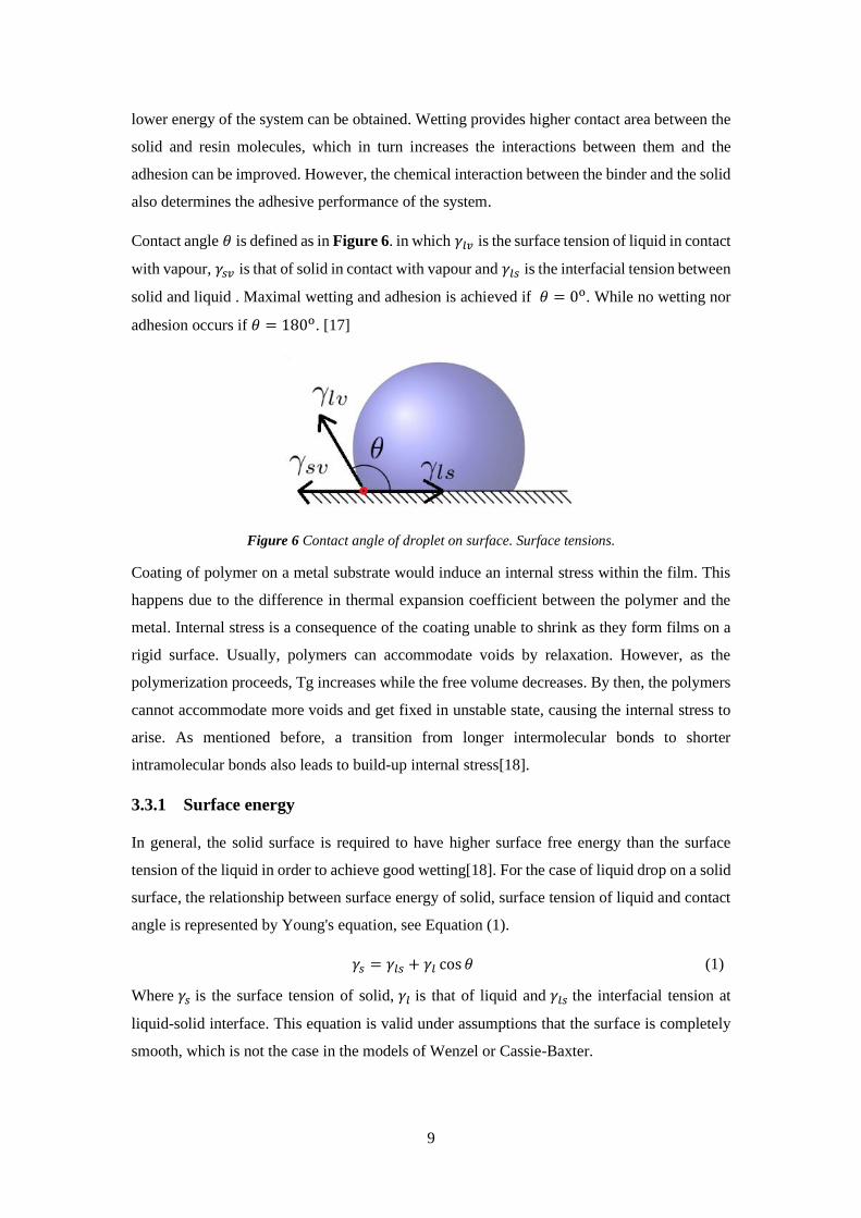
Contact angle 𝜃 is defined as in Figure 6. in which 𝛾𝑙𝑣 is the surface tension of liquid in contact
with vapour, 𝛾𝑠𝑣 is that of solid in contact with vapour and 𝛾𝑙𝑠 is the interfacial tension between
solid and liquid . Maximal wetting and adhesion is achieved if 𝜃 = 0o. While no wetting nor
adhesion occurs if 𝜃 = 180o. [17]
Figure 6 Contact angle of droplet on surface. Surface tensions.
Coating of polymer on a metal substrate would induce an internal stress within the film. This
happens due to the difference in thermal expansion coefficient between the polymer and the
metal. Internal stress is a consequence of the coating unable to shrink as they form films on a
rigid surface. Usually, polymers can accommodate voids by relaxation. However, as the
polymerization proceeds, Tg increases while the free volume decreases. By then, the polymers
cannot accommodate more voids and get fixed in unstable state, causing the internal stress to
arise. As mentioned before, a transition from longer intermolecular bonds to shorter
intramolecular bonds also leads to build-up internal stress[18].
3.3.1 Surface energy
In general, the solid surface is required to have higher surface free energy than the surface
tension of the liquid in order to achieve good wetting[18]. For the case of liquid drop on a solid
surface, the relationship between surface energy of solid, surface tension of liquid and contact
angle is represented by Young's equation, see Equation (1).
𝛾𝑠 = 𝛾𝑙𝑠 + 𝛾𝑙 cos 𝜃 (1)
Where 𝛾𝑠 is the surface tension of solid, 𝛾𝑙 is that of liquid and 𝛾𝑙𝑠 the interfacial tension at
liquid-solid interface. This equation is valid under assumptions that the surface is completely
smooth, which is not the case in the models of Wenzel or Cassie-Baxter.

10
3.3.2 Surface roughness
Surfaces of solids are rarely smooth but contains bumps and undercuts, see the surfaces
(Wenzel or Cassie Baxier) in Figure 7. An increase in roughness means increase in possible
contact area which would improve the adhesion[18].
Figure 7 Contact angle theta - Microstates (Wenzel, Cassier Baxler). Types of liquid wetting on
different surfaces[19].
However, only a complete penetration of coating resin into the surface crevices can create
mechanical interlocking which will increase the adhesion. This does not work if penetration is
partial/incomplete because in this case, the contact area is low. In addition, possible impurities
in the film would penetrate to the voids into the crevices and decrease the surface energy of the
solid, which in turn worsen wetting[18].
The idea about increasing the surface roughness to increase the interfacial contact area is used
in conversion coating. During pretreatment when steel is immersed in a solution of conversion
coating, this coating molecules etches slightly into the surface of the metal and precipitations
of ferrous phosphates are formed. The phosphate crystals are deposited on the surface, creating
crevices into which the coating resin can penetrate. The resin molecules can form hydrogen
bonding better with the phosphate crystals than with steel. Hence, the penetration into the
crystal mesh of phosphates is easier[18].
A higher penetration of coating resin would increase the adhesion and it can be achieved by
increasing the time of penetration. Thus a low viscosity, slow cross-linking rate, using low
molecular weight resin and low evaporating solvents will give good adhesion[18].
3.3.3 Interfacial bonding
Enhanced adhesion can be achieved with hydrogen bonding between the binder and the surface
molecules. Clean steels have a layer of hydrated iron oxides which can form hydrogen bonds
with the related functional groups of the resin molecules. Phosphates from conversion coatings
provides more hydrogen bonding interaction. Resin molecules that have multiple hydrogen
bonding accepting - and donating groups will promote adhesion. For example, the functional
11
groups can be amines, carboxylic acids, hydroxides, urethane and phosphates. Therefore,
bisphenol A epoxy acrylates and epoxides are used as binders, for example in the UV-curable
formulations used in this experiment.
4 EXPERIMENT
The experiment part involves a screening and an industrial application study. The screening
study focused on the curing parameters such as UV-dosage, curing environment, concentration
of initiator in the cationic formulation; also, the possibility for curing with UV-LED and on
mussel adhesive proteins substrate (MAP). In the industrial application study, the metal
substrates were coated with a UV-coat and a topcoat. Those samples were then tested for
adhesive performance, flexibility and impact resistance.
4.1 Materials
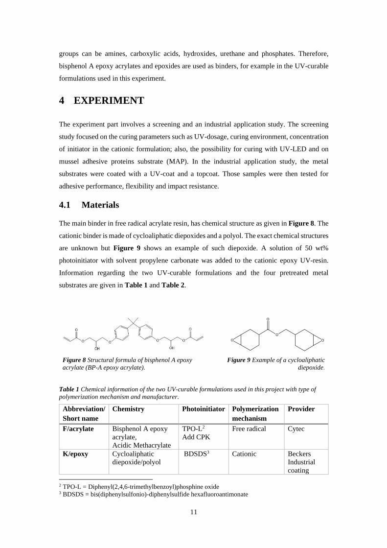
The main binder in free radical acrylate resin, has chemical structure as given in Figure 8. The
cationic binder is made of cycloaliphatic diepoxides and a polyol. The exact chemical structures
are unknown but Figure 9 shows an example of such diepoxide. A solution of 50 wt%
photoinitiator with solvent propylene carbonate was added to the cationic epoxy UV-resin.
Information regarding the two UV-curable formulations and the four pretreated metal
substrates are given in Table 1 and Table 2.
Figure 8 Structural formula of bisphenol A epoxy
acrylate (BP-A epoxy acrylate).
Figure 9 Example of a cycloaliphatic
diepoxide.
Table 1 Chemical information of the two UV-curable formulations used in this project with type of
polymerization mechanism and manufacturer.
Abbreviation/
Short name
Chemistry Photoinitiator Polymerization
mechanism
Provider
F/acrylate
Bisphenol A epoxy
acrylate,
Acidic Methacrylate
TPO-L2
Add CPK
Free radical Cytec
K/epoxy Cycloaliphatic
diepoxide/polyol
BDSDS3 Cationic Beckers
Industrial
coating
2 TPO-L = Diphenyl(2,4,6-trimethylbenzoyl)phosphine oxide 3 BDSDS = bis(diphenylsulfonio)-diphenylsulfide hexafluoroantimonate

12
Table 2 Pretreated metal substrates.
Substrate Substrate condition/pretreatment Provider
Metal PO Untreated Z275, cold rolled, degreased/
Standard Ti-pretreatment
PTE Coatings
AB, Sweden
Metal PP Untreated Z275, cold rolled, degreased/
Pretreatment Primer (acrylate/polyurethane clearcoats)
Top Analytica,
Finland
Metal UP Untreated Z275, cold rolled, degreased/ Standard Ti-
pretreatment, coated with 6 m Universal Primer
(polyester/melamine)
PTE Coatings AB
Sweden
Metal US
Untreated Z275, cold rolled/ - Top Analytica
Metal
MAP
Untreated Z275, cold rolled, degreased /
Pretreated with Mussel Adhesive Proteins(MAP)[20]
SSAB/KTH Surface
Chemistry and
Corrosion Science
4.2 Analysing Techniques
The surface characterization was done using atomic force microscopy (AFM) and contact angle
measurement (CAM). Film properties analysed by Fourier Transform Infrared Spectroscopy
(FT-IR) and dynamic mechanical analysis (DMA). The impact resistance and adhesion were
measured using impact tester combined with cross-hatch tester.
4.2.1 Coating thickness measurement
The coating thickness was measured using both FischerScope MMS PC2 and a drill instrument
DJH Design Inc (Canada). Fischerscope measured the total thickness, including all coatings
down to the metal surface, excluding the Zinc layer. The thicknesses of the topcoat respective
primer were analysed using FischerScope and the drill. The UV-coating is calculated by
subtracting the thickness of the primer and the topcoat from the total thickness.
4.2.2 Atomic Force Microscopy
Surface topology on nanoscale and roughness were analysed using AFM of model Bruker
Nanoscope V, the results were analysed further with software Nanoscope Analysis 1.5.
Scanning performed with ScanAsyst mode with following settings: in air, scan size 5µm x 5µm,
aspect ratio 1, scan angle 0.00o, scan rate is 0.3 Hz and 512 samples/line.
4.2.3 Contact Angle Measurement
Contact Angle measurement was conducted using KSV Instruments LTD CAM200 in sessile
drop mode. Droplet size of water was 3 µL and recording time was 40 seconds for both non-
coated and UV-coated samples. When measuring with iodomethane, the droplet size was 2 µm
and recording time 40 seconds for all samples except for UP-samples which were recorded for
around 100 seconds. Ten repetitive measurements were done and those measurements that gave

13
large deviation in volume(±0.5 μL) were filtered out. The contact angles measured between 20
and 30 seconds were collected, averaged and calculated for a standard deviation.
4.2.4 Fourier Transform Infrared Spectroscopy
The degree of curing was followed using PerkinElmer Spectrum 2000 FT-IR instrument. The
resolution was 4 cm-1 and 8 scans. For the acrylate formulation, the conversion is determined
by the disappearance of the acrylate (C=C) double bonds at 1637 cm-1. While for the epoxy
formulation, the curing is followed by the disappearance of the epoxide (C-O-C) at 910 cm-1
and increasing peak of aliphatic ether at 1073 cm-1. Normalization was done against carbonyl
(C=O) of the ester group at 1724 cm-1 for epoxy formulation and 1722 cm-1 for the acrylate
system.
4.2.5 Dynamic Mechanical Analysis
The intrinsic mechanical properties of the films were analysed using TA Instruments Q800 in
Multi-Frequency-Strain mode. Tension film testing between -25oC and 150oC with soak time
10 minutes, ramping 3oC/min. Strain was set to 0.1% and preload force was 0.01 N. The films
were cut into rectangular stripes 6 mm x 20 mm, width and length. The acrylate films were
approximately 0.1 mm thick while the epoxy films had thicknesses around 0.04 mm.
4.2.6 Impact testing and crosshatch testing
The impact resistant and adhesion were measured using impact tester from Braive Instrument.
A load corresponding to 100 kg cm and the penetration depth was set to number 4. This setting
was a standard being used at the coating line at SSAB Finspång.
4.3 Screening Study
This part of experiment involves studying how different factors can affect the curing of the
UV-curable formulations. Both glass and common steel plates were used.
4.3.1 Effect of dose and thermal post-cure
The effect of dose and thermal post-curing were investigated by coating on glass and metal
plates. All samples were cleansed with methanol followed by acetone and lastly with air
blowing. UV Fusion Lamp was used as energy source and the conveyor belt Fusion Series
model MC6R was used to adjust intensity of the light given to the metal substrates. The coated
samples were given certain doses, analysed with FT-IR, and thermally post-cured at 70oC in an
oven.
14
4.3.2 Effect of photoinitiator concentration
Determination of the optimal photoinitiator concentration was done by adding different amount
of photoinitator in the epoxy resin to get the proportions: 3 wt%, 4wt%, 5wt%, 6wt% and
30wt%. Respective solutions were mixed using vortex mixer, wrapped up in aluminium foil
and stored immediately in the fridge if not used.
4.3.3 Effect of using UV-LED lamp
A UV-LED lamp emitting maximum light at 365 nm with exposure area 10 x 10 cm2 was used.
Sample was placed 4.6 cm under the light source and the intensity was 0.750 W cm-2 with a
dose of 4.034 J cm-2 for 6 seconds exposure. The instrument was set to 100% intensity. Both
formulations were applied, on anti-graffiti metal plate and MAP-substrate respectively. The
curing was done both with and without the presence of nitrogen gas.
4.4 Industrial Application
The metal substrates were coated with UV-curable formulation using a bar coater (number 3)
and cured under UV-light(UV Fusion Lamp) on a running conveyor belt with velocity 14.13
meter/minute. Seven passages at this velocity corresponded to an average total dose of 0.965
J cm-2 at intensity ~0.576 J cm-2. These values are approximate as taken as an average from
several measurements and are in the range of UV-A.
A topcoat GreenCoat BT Pro was applied onto all metal substrates; thermally cured at 243oC;
cooled down in water for around 6 seconds, which corresponds to the time it takes for the door
to the oven to close. All samples were cured directly except for acrylate-PP samples which
required a preheating around 25 to 26 seconds (temperature of oven is 365 oC before getting
coated with topcoat and thermally cured. Unevenness in topcoat if preheating was ignored and
this could be caused by possible moist and solvents remaining in the topcoat.

15
5 RESULTS & DISCUSSION
In this chapter, the mechanical properties of topcoated steel substrates will be presented first,
which is then followed by a section about coating material properties and lastly the screening
studies where surface characteristics and curing parameters are discussed. Table 3 lists all steel
substrates and their corresponding abbreviations.
Table 3 Sample names and abbreviations.
Coating
Steel substrates
No coating UV-coat
F – free radical
K – cationic
Topcoat TC
Standard Ti-
pretreatment PO
POF
POK
POF – TC
POK – TC
Pretreatment
Primer PP
PPF
PPK
PPF – TC
PPK – TC
Universal Primer UP UPF
UPK
UPF – TC
UPK – TC
Unpassivated Steel
HDG US
USF
USK
–
–
5.1 Adhesive performance
Evaluation of the adhesive performance of the UV-coat is based on the results obtained from
impact testing and crosshatch adhesion test. Specifically, T-bend measures the flexibility of
the coating while crosshatch test determines how good the coating adheres to the metal
substrates.
5.1.1 T-bend
Figure 10 shows the edges of the coated metal substrates after having undergone T-bend
measurement. It should be noted that at the time of the experiment, no cracks could be observed.
But one day after the experiment, cracks and delamination coatings were detected. The picture
in Figure 10 was taken two days after the experiment and the cracks have propagated even
more for sample UPF(Figure 10e). The yellow marks in the figure indicates the position of the
last crack that appeared one day after the time of testing.
16
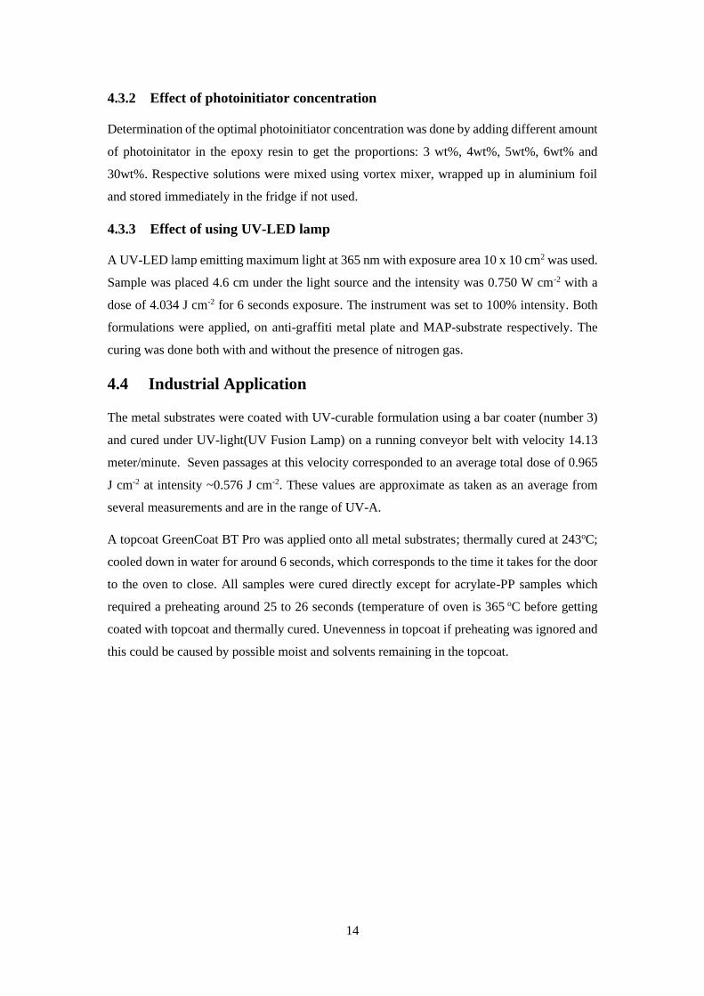
Figure 10 Samples undergone T-bend. The yellow lines mark the position of last cracks observed, after
1 day from the actual time of experiment. This picture was taken 2 days after the experiment.
Judging from the observations mentioned above, crack propagation must have happened to the
film. When compared between acrylate and epoxy samples, the acrylate ones(F) have worst
flexibility. The coatings on POF and UPF were delaminated while PPF adheres slightly better
than those two. In the case of epoxy UV-coated samples, cracks in different sizes can be seen
but no complete delamination. The white lines on these samples are only light reflections.
Despite being more intact, their flexibilities are also bad in comparison to industrial standards
in which bending radius is maximum 3T[21].
Table 4 Minimum bending radius and corresponding T-bend values of topcoated steel substrates.
Minimum Bending radius [mm] T-bend value
POF -TC 6.25 5T
POK -TC 4.40 3T
PPF -TC 6.86 5T
PPK -TC 5.23 3T
UPF -TC 4.49 4T
UPK -TC 4.15 3T
5.1.2 Impact test and crosshatch adhesion test
The UPF sample in Figure 11e) did have all topcoat intact at the time of the experiment. This
picture shows the state of the sample after being ripped by tape for a second time, 24 hours
after the experiment. This fact supports the idea about time-dependent crack propagation.
POF shows no adhesion between coating and the metal substrate. This confirms earlier
suspicions that the free radical acrylate formulation would not cure on Standard Ti-pretreatment
since there is something in this formulation that works as radical scavenger. The acrylate film
did cure on this surface but perhaps not at the metal/film interface which led to delamination.
Another failure is the PPK sample in which the coating delaminates, and this is expected.

17
Because of the high basicity (pH ~ 11) in the pretreatment primer in PP, the acid catalysed
cationic reaction is inhibited and result in low to no curing at the metal/coat interface.
Figure 11 Samples after impact testing and cross-hatch testing. Pictures taken two days after the
experiment. Note that the original colours of the samples are the same, the difference in colour is due to
the camera.
Based on the results presented in Figure 11, the epoxy UV-coating adheres to two metal
substrates while the acrylate type only adheres to one. One of the reasons can be the internal
stress which arises from the curing of acrylates in acrylate formulation. But this does not mean
that the epoxy formulation has better adhesion than the acrylate one, since the samples have
different thicknesses and thus cannot be compared on the equal term , see Figure 12. The
thickness of each UV-coat was estimated by subtracting the thickness of the topcoat (20 µm)
and the primer. Detailed thickness of the layers can be found in Table 6 in Appendix.
a) UPF-TC with total coating thickness 84.12
m, UV-coating thickness 58 m.
b) UPK-TC with total coating thickness 33.66
m, UV-coating thickness 7.66 m.
Figure 12 Microscopic image of drilled hole on top-coated sample for thickness determination. The
white part is the UV-coat.

18
From the calculation, the thickness of the acrylate UV-coats varies between 41 – 78 µm while
that of the epoxy UV-coats is between 8 and 11 µm, the numbers are rounded up to the closest
integer. The thickness of the UV-coat in these samples overrides the intended thickness which
should be between 12 – 15 µm. As discussed previously, a thick UV-coat results in a stronger
absorption at the top layer of the coat. Almost all UV light energy is thus deposited at there
which leads to an inhomogeneous deposition of energy across the depth of the film.
5.2 Surface characteristics
The hydrophilicity of different sample surfaces was determined by measuring contact angle of
water droplet after being deposited on the surfaces. Surface topology in nanoscale was studied
using AFM. In AFM, the samples USK and USF could not be analysed since they were too
rough.
5.2.1 Hydrophilicity or hydrophobicity
Using water as testing liquid, the contact angles vary between the different non-coated samples.
Most have hydrophilic surfaces with unpassivated steel being at the border of being hydrophilic
and hydrophobic. An observation through microscope, not presented here, showed that US-
substrates have the roughest surface of all types and this was partly due to the sandblasting.
Perhaps its higher contact angle is related to Cassie-Baxter model in which the liquid covers
the crevices but not penetrate them.
A general observation from Figure 13 is that the contact angles probably rely on the chemistry
and the topology of the actual surface. For example, the blue bars represent the four types of
metal substrates coated with the same acrylate UV-coating and all the contact angles of this
groups are reduced to ~ 50o. Meanwhile, the red bars with epoxy UV-coat have contact angles
above 80o. Same thing happens with the topcoated samples, green and black bars.
When comparing between the two UV-curable formulations, the acrylate UV-coat appears to
increase the hydrophilicity of the samples while the epoxy coat decreases it. The contributing
factors for hydrophilicity in the acrylate coat are the aromatic ring structures; the ester
functionality RCOOR and the hydroxy OH-groups in the backbone chains. The polymerized
epoxy network is made of non-polar polyether network which explains its hydrophobicity.
Most probably, the hydrophobicity in the epoxy system helps improve adhesion to the topcoat,
as the topcoat is also has similar hydrophobic character, which leads to the positive adhesion
results in section 5.1.2. There are possibilities that the polyether functionalities dissolve in the
topcoat resin which contains fatty acid methyl ester (FAME) and binds to the binder.

19
Figure 13 Contact angles of water droplet on different surfaces. Beige bars signify original non-coated
metal samples, the blue bars have acrylate UV-coated surfaces, The red ones are coated with epoxy UV-
curable formulation; green means topcoated samples with acrylate UV-coat underneath; black bars are
topcoated samples with epoxy UV-coat under.
With the contact angle less than 90o, the epoxy coat is still hydrophilic but is has more
hydrophobic characteristic than the acrylate one. It is probably the roughness that has positive
effects on the contact angles since the epoxy resin did not wet the surface of the substrates but
form wavy textures on the surface.
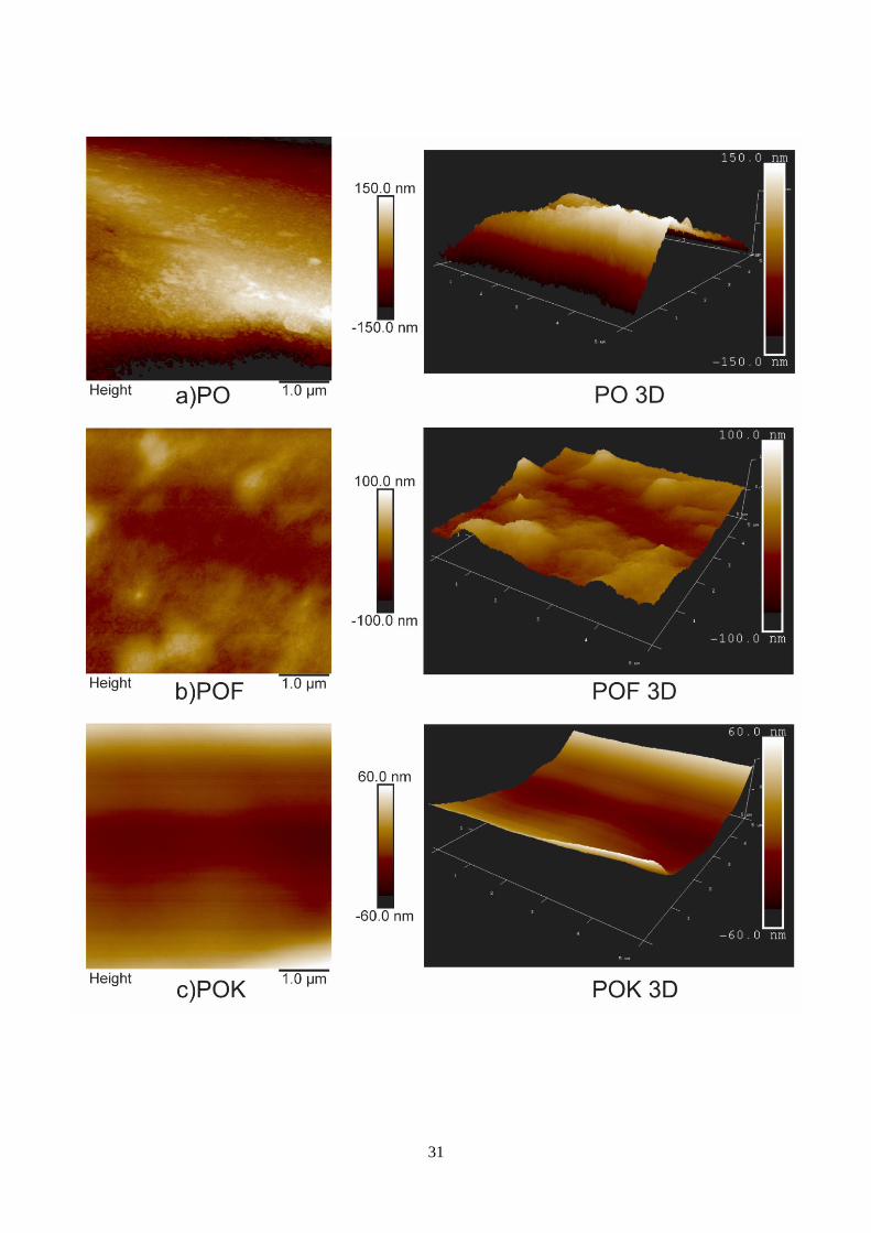
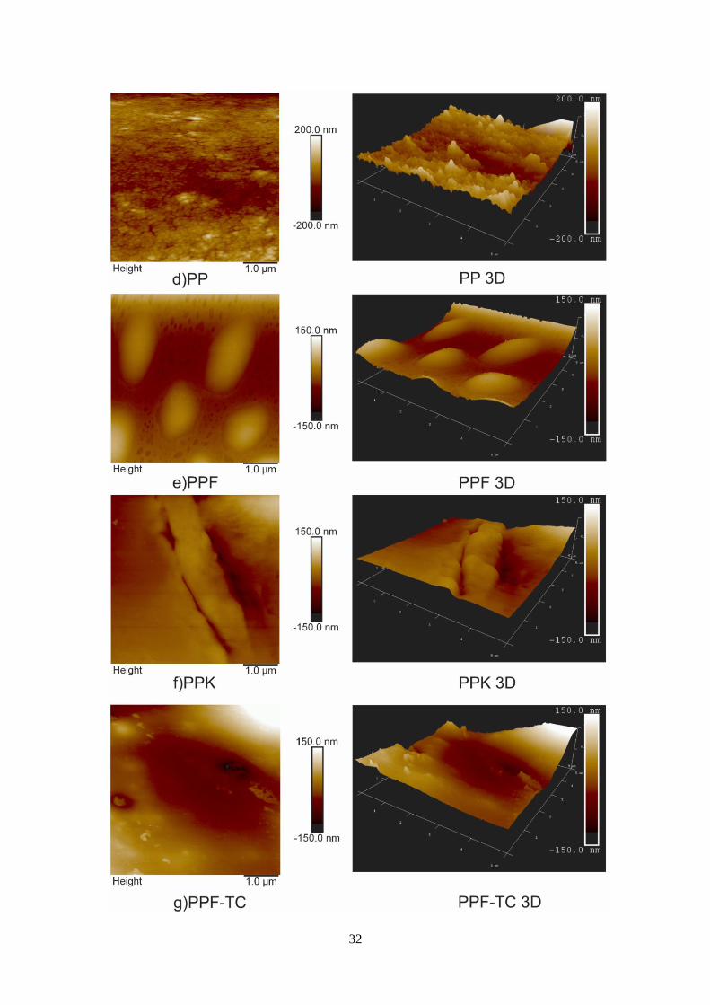
5.2.2 Morphology and roughness
Surface image and roughness have been analysed using AFM, but it is not possible to conclude
which of the samples has the roughest surface. An observation through microscope showed UP
appeared to have the smoothest surface amongst all samples while US had the roughest surface
among all. But the measured roughness from AFM indicates UP is the roughest. The difference
in these observations can be reasoned with the fact that AFM analysed a very small area of 5x5
µm2, in which the roughness is measured in nanoscale. In addition, the measured roughness
depends greatly on whether the scan region is in, outside or at the edge of the crevices. An
important notion is that there are large grains of melamine in the formulation of universal
primer and thus the surface of UP inherits some rough parts where the particles are found.
From Figure 14, PP seems to have the least rough surface than the rest. It appears as if there
are small grains filling the surface of PP and this has positive effect on adhesion mechanism as
smoother surface facilitates the contact between resin molecules and those belonging to the
surface.

20
Figure 14 AFM images of the four original metal substrates PO, PP, UP, US. The images represent
the surfaces looing from above and the colour scales shows the difference in height.
The purpose of using AFM is to determine the roughness of the surface and perhaps amplify
the results from CAM. The AFM images obtained do not have the same scale which makes it
not possible to compare. It could not be done otherwise because the epoxy UV-coated samples
have much smaller roughness scale which makes them seem very flat when getting similar
height scale as the other samples.
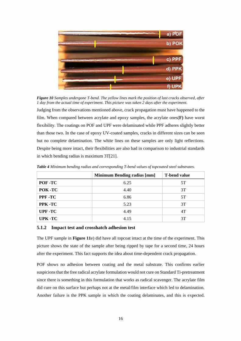
Figure 15 shows that the non-coated metal substrates have higher and diverse roughness
distribution than the coated samples. Roughness can be considered as the distribution of peaks
and valleys on a surface; or the vertical height of these features. Therefore, parameters such as
skewness and kurtosis are of interests, see Appendix Figure 23. However, this should not be
taken as completely true since it was noticed that, depending on the scanning region, the
roughness of the same sample can vary a lot. Due to time limitation, repetitive AFM scan could
not be performed. Thus, to get more reliable results, repetitive analysis should be performed.
a) PO
b) PP
c) UP
d) US
21
Figure 15 Distribution of surface roughness of steel samples. Measured on scan size 5 × 5 𝜇𝑚2 using
AFM.
5.3 Material properties
5.3.1 Film stiffness and glass transition temperature Tg
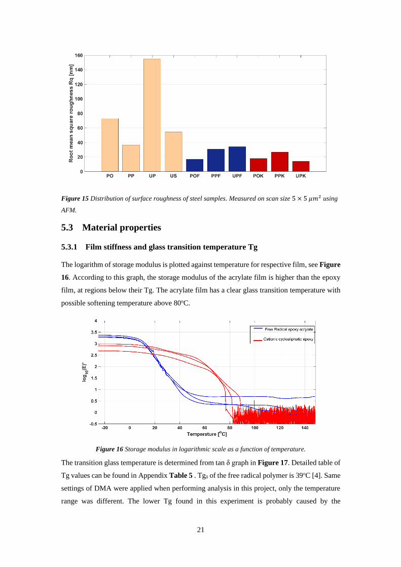
The logarithm of storage modulus is plotted against temperature for respective film, see Figure
16. According to this graph, the storage modulus of the acrylate film is higher than the epoxy
film, at regions below their Tg. The acrylate film has a clear glass transition temperature with
possible softening temperature above 80oC.
Figure 16 Storage modulus in logarithmic scale as a function of temperature.
The transition glass temperature is determined from tan δ graph in Figure 17. Detailed table of
Tg values can be found in Appendix Table 5 . Tgδ of the free radical polymer is 39oC [4]. Same
settings of DMA were applied when performing analysis in this project, only the temperature
range was different. The lower Tg found in this experiment is probably caused by the
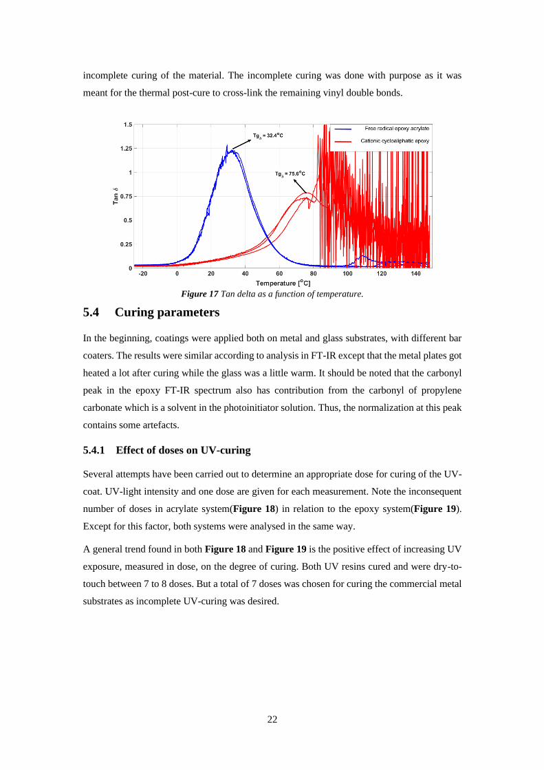
22
incomplete curing of the material. The incomplete curing was done with purpose as it was
meant for the thermal post-cure to cross-link the remaining vinyl double bonds.
Figure 17 Tan delta as a function of temperature.
5.4 Curing parameters
In the beginning, coatings were applied both on metal and glass substrates, with different bar
coaters. The results were similar according to analysis in FT-IR except that the metal plates got
heated a lot after curing while the glass was a little warm. It should be noted that the carbonyl
peak in the epoxy FT-IR spectrum also has contribution from the carbonyl of propylene
carbonate which is a solvent in the photoinitiator solution. Thus, the normalization at this peak
contains some artefacts.
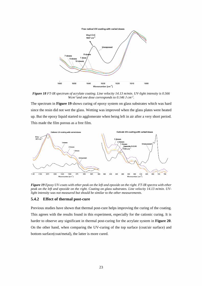
5.4.1 Effect of doses on UV-curing
Several attempts have been carried out to determine an appropriate dose for curing of the UV-
coat. UV-light intensity and one dose are given for each measurement. Note the inconsequent
number of doses in acrylate system(Figure 18) in relation to the epoxy system(Figure 19).
Except for this factor, both systems were analysed in the same way.
A general trend found in both Figure 18 and Figure 19 is the positive effect of increasing UV
exposure, measured in dose, on the degree of curing. Both UV resins cured and were dry-to-
touch between 7 to 8 doses. But a total of 7 doses was chosen for curing the commercial metal
substrates as incomplete UV-curing was desired.
23
Figure 18 FT-IR spectrum of acrylate coating. Line velocity 14.13 m/min. UV-light intensity is 0.566
Wcm-2and one dose corresponds to 0.146 J cm-2.
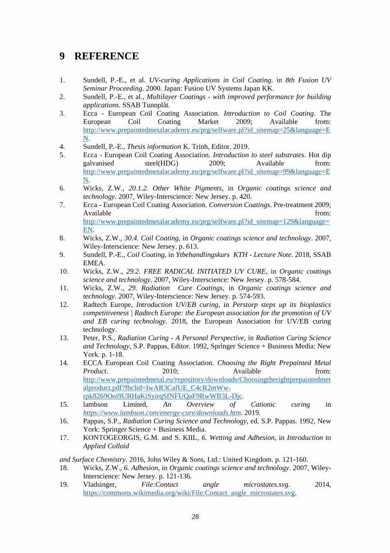
The spectrum in Figure 19 shows curing of epoxy system on glass substrates which was hard
since the resin did not wet the glass. Wetting was improved when the glass plates were heated
up. But the epoxy liquid started to agglomerate when being left in air after a very short period.
This made the film porous as a free film.
Figure 19 Epoxy UV-coats with ether peak on the left and epoxide on the right. FT-IR spectra with ether
peak on the left and epoxide on the right. Coating on glass substrates. Line velocity 14.13 m/min. UV-
light intensity was not measured but should be similar to the other measurements.
5.4.2 Effect of thermal post-cure
Previous studies have shown that thermal post-cure helps improving the curing of the coating.
This agrees with the results found in this experiment, especially for the cationic curing. It is
harder to observe any significant in thermal post-curing for the acrylate system in Figure 20.
On the other hand, when comparing the UV-curing of the top surface (coat/air surface) and
bottom surface(coat/metal), the latter is more cured.

24
Figure 20 Line velocity 14.13 m/min. UV-light intensity is 0.566 Wcm-2and one dose corresponds to
0.146 J cm-2. Seven doses of UV-light were provided for the curing. Thermal post-cure overnight at 70oC.
Though the difference is very little, it can still be seen that the curing after thermal post-cure is
better than before, see Figure 21. The thermal curing is relevant for the cationic system since
this is a living polymerization in which the curing is completed when all acids or epoxides have
been used up. Inducing heat in the cross-linked network increases its flexibility, thereby
bringing the reacting species closer together.
Figure 21 Epoxy UV-coats with ether peak on the left and epoxide on the right. Line velocity 14.13
m/min. UV-light intensity is 0.584 Wcm-2and one dose corresponds to 0.134 J cm-2. Thermal post-cure
at 70oC for 2 hours.
5.4.3 Effect of photoinitiator concentration on curing
The epoxy formulation was provided as a resin and separate photoinitiator. This allowed for
the possibilities for tailoring a formulation suitable for a chosen thickness. The aim in this study
is to evaluate the lowest concentration of photoinitiator that can provide highest through cure
at thickness around 15 µm. Lowest amount of photoinitiator is desired from industrial
perspective as it is expensive.
Thus, an observation at the spectrum in Figure 22 shows that 4wt% is the best concentration.
In addition, the 3 wt% resin could not give adequate curing as the coat was not dry-to-touch
after seven doses. The 30 wt% resin gave a very dense/opaque coat with strong odour which

25
probably came from the solvent propylene carbonate in photoinitiator solution. The odour
gradually disappeared after thermal post-cure.
Figure 22 Top side of epoxy UV-coats with ether peak on the left and epoxide on the right. Line velocity
14.13 m/min. UV-light intensity is 0.584 Wcm-2and one dose corresponds to 0.134 J cm-2.
5.4.4 Curing with UV-LED
An observation was carried out about the curing of both UV-curable formulations under UV-
LED, with and without the presence of nitrogen gas. Both systems cured well except that the
acrylate coating became sticky when cured in air; but the stickiness was absent when curing
was proceeded in nitrogen gas. These results provide evidence for oxygen inhibition. Since
stickiness is a characteristic of hydroperoxyl groups.
The two UV-curable formulations cure well on MAP substrate. The epoxy coating was dry-to-
touch after 6 seconds of curing while the acrylate coating had a sticky surface even after 21
seconds. As the stickiness did not disappear even after such long period of time, the experiment
was terminated as it was believed that higher dose would not improve the curing at the surface.
One of the major differences in curing under Fusion lamp respective LED lamp is that the metal
plates were heated when cured under Fusion lamp; while they remain at room temperature
under LED lamp. Heating increases dissolution of oxygen into the coating which means curing
under Fusion lamp should have curing problems, but it was not the case. Most probably, the
curing temperature does not have major effect on oxygen inhibition.
The monochromaticity of the LED lamp is another obvious difference that may affect the
oxygen inhibition in free radical formulation. The resin contains photoinitiator TPO-L4 which
has maximal absorption at 380 nm and photoinitiator Add CPK absorbing at 276 and 326
nm[22, 23]. Because Add CPK serves as initiator for surface curing and it does not absorb the
wavelength emitted by the LED lamp, the dissolution of oxygen into the coating at the surface
is facilitated. This leads to a more pronounced effect of oxygen inhibition when curing in UV-
4 TPO-L: Ethyl (2,4,6-trimethylbenzoyl) phenyl phosphinate

26
LED. On the other hand, the cationic BDSDS absorbs at 366 nm which explains why it cured
without difficulties. In addition, the total energy delivered by Fusion lamp covers also shorter
wavelengths which explains why acrylate cures effectively under this type of UV lamp.
5.5 General discussion and sources of error
The industrial application study had been disrupted due to the failure of applying the right
thickness of the acrylate UV-coating. This had led to some incomparable results, for example
between the acrylate and epoxy system. Measures had been taken such as keeping the metal
plates planar; applying evenly pressure along the bar; cleaning the bar coater in between the
coating and heating the plates to temperature around 50oC. But it was found that the adopted
cleaning method was inadequate, and the highly viscous resin might have caused hydroplaning
when pulling the bar coater.
The results show that crack propagation happens in the coating. It would have been better if
the analysis was done directly after the experiment in order to have comparable data.
Furthermore, the sample preparation for AFM analysis was also bad in a way that the samples
were pressed to become very flat. This flattening of surface could have destroyed or alter the
appearance of the surface. Analysis on skewed samples has been carried out without success.
6 CONCLUSION
Coil coating using UV as energy source is a promising industrial application, especially UV-
LED as it was found that the both UV-curable formulations used in this project cured under the
UV-LED lamp. This study confirms some hypotheses that there are free radical scavengers in
Standard Ti-pretreatment that prevents curing of the free radical UV-curable formulation; also,
the basicity in pretreatment primer leads to bad curing of cationic coating and thus bad adhesion
to the metal substrate. The acrylate UV-coat is hydrophilic while the epoxy UV-coat has a more
hydrophobic character. AFM is a powerful method to imaging the surfaces, but more repetitive
analysis should be carried out for respective surfaces for reliable conclusions.
7 FUTURE WORK
• Using the UV-LED lamp as energy source and perform curing both with and without
nitrogen gas. Focus on observing whether oxygen inhibition would have effect on
adhesion to topcoat. The hydroperoxyl groups might be able to dissociate in the resin
of topcoat and bind to the polyester groups.

27
• Ensure the availability of all necessary lab equipment’s. For example, the right bar
coater with cleansing tools, magnet table which ensures completely flat surface and
thus even coating layer.
• Comparing between different UV systems such as modified polyester, epoxy-acrylate
and urethane acrylate. Analyse coated samples at the time of the experiment and after
a certain interval.
• Perform repetitive AFM measurements and consider skewness and kurtosis when
analysing the results.
• Further investigations on MAP which is an environmentally friendly pretreatment of
the coil.
8 ACKNOWLEDGEMENTS
I would like to express my most sincere gratitude to my supervisor Per-Erik Sundell and co-
supervisor/examiner Mats Johansson for all guidance, support, teaching and inspiration during
this project. I am particularly grateful to Tomas Deltin and co-workers from PTE Coatings in
Gamleby, and co-workers from SSAB in Finspång, for letting me work at your labs and for
your hospitality. Advice given by all co-workers from SSAB has been a great help in this
project. Thank you Li Zha for your contribution regarding MAP. My special thanks to all
colleagues from division of coating technology and department of fiber and polymer
technology, for all kindness, support, and trainings I have received. This project would not have
been possible and fun without your help.
To my family and friends, thank you for having been there for me.
28
9 REFERENCE
1. Sundell, P.-E., et al. UV-curing Applications in Coil Coating. in 8th Fusion UV
Seminar Proceeding. 2000. Japan: Fusion UV Systems Japan KK.
2. Sundell, P.-E., et al., Multilayer Coatings - with improved performance for building
applications. SSAB Tunnplåt.
3. Ecca - European Coil Coating Association. Introduction to Coil Coating. The
European Coil Coating Market 2009; Available from:
http://www.prepaintedmetalacademy.eu/prg/selfware.pl?id_sitemap=25&language=E
N.
4. Sundell, P.-E., Thesis information K. Trinh, Editor. 2019.
5. Ecca - European Coil Coating Association. Introduction to steel substrates. Hot dip
galvanised steel(HDG) 2009; Available from:
http://www.prepaintedmetalacademy.eu/prg/selfware.pl?id_sitemap=99&language=E
N.
6. Wicks, Z.W., 20.1.2. Other White Pigments, in Organic coatings science and
technology. 2007, Wiley-Interscience: New Jersey. p. 420.
7. Ecca - European Coil Coating Association. Conversion Coatings. Pre-treatment 2009;
Available from:
http://www.prepaintedmetalacademy.eu/prg/selfware.pl?id_sitemap=129&language=
EN.
8. Wicks, Z.W., 30.4. Coil Coating, in Organic coatings science and technology. 2007,
Wiley-Interscience: New Jersey. p. 613.
9. Sundell, P.-E., Coil Coating, in Ytbehandlingskurs KTH - Lecture Note. 2018, SSAB
EMEA.
10. Wicks, Z.W., 29.2. FREE RADICAL INITIATED UV CURE, in Organic coatings
science and technology. 2007, Wiley-Interscience: New Jersey. p. 578-584.
11. Wicks, Z.W., 29. Radiation Cure Coatings, in Organic coatings science and
technology. 2007, Wiley-Interscience: New Jersey. p. 574-593.
12. Radtech Europe, Introduction UV/EB curing, in Perstorp steps up its bioplastics
competitiveness | Radtech Europe: the European association for the promotion of UV
and EB curing technology. 2018, the European Association for UV/EB curing
technology.
13. Peter, P.S., Radiation Curing - A Personal Perspective, in Radiation Curing Science
and Technology, S.P. Pappas, Editor. 1992, Springer Science + Business Media: New
York. p. 1-18.
14. ECCA European Coil Coating Association. Choosing the Right Prepainted Metal
Product. 2010; Available from:
http://www.prepaintedmetal.eu/repository/downloads/Choosingtherightprepaintedmet
alproduct.pdf?fbclid=IwAR3CafUE_C4cR2mWw-
rpk8269Ooi9URHaKiSyirqSfNFUQaF9RwWB3L-Djc.
15. lambson Limited, An Overview of Cationic curing in
https://www.lambson.com/energy-cure/downloads.htm. 2019.
16. Pappas, S.P., Radiation Curing Science and Technology, ed. S.P. Pappas. 1992, New
York: Springer Science + Business Media.
17. KONTOGEORGIS, G.M. and S. KIIL, 6. Wetting and Adhesion, in Introduction to
Applied Colloid
and Surface Chemistry. 2016, John Wiley & Sons, Ltd.: United Kingdom. p. 121-160.
18. Wicks, Z.W., 6. Adhesion, in Organic coatings science and technology. 2007, Wiley-
Interscience: New Jersey. p. 121-136.
19. Vladsinger, File:Contact angle microstates.svg. 2014,
https://commons.wikimedia.org/wiki/File:Contact_angle_microstates.svg.

29
20. Zhang, F., The Mussel Adhesive Protein (Mefp-1) — A GREEN Corrosion Inhibitor,
in Department of Chemistry Division of Surface and Corrosion Science. 2013, KTH
Royal Institute of Technology: Stockholm.
21. Nordin, I. and J. Karlsson, Arbetsintruktion Bestämning av flexibilitet genom T-bend.
2018: Finspång.
22. Lambson Limited, Product range Photoinitiators & UV curing, L. Limited, Editor.
2018, Lambson Limited: West Yorkshire, UK. p. 13.
23. Allnex Group, Technical Datasheet Additol(R) CPK Alpha Cleavage Photoinitiator.
2018.
24. Green, W.A., Industrial Photoinitiator A technical guid. 2010, United States of
America: CRC Press.
10 APPENDIX
Table 5 Measured glass transition temperature tan δ, from DMA.
Tgδ [oC] Average Tgδ [oC]
Acrylate film 1 32.2937
32.4 Acrylate film 2 32.0511
Acrylate film 3 32.9133
Epoxy film 1 75.8532
75.6 Epoxy film 2 76.298
Epoxy film 3 74.6675
Table 6 Estimation of UV-coating thickness on six different metal substrates with the same topcoat.
Assume the thickness of primer to be the same in each category and that of the topcoat is 20 µm.
Total coat
thickness [µm]
Primer
thickness [µm]
Topcoat
thickness [µm]
UV coat
thickness [µm]
POF-TC 60.99 0 20 40.99
POK-TC 29.93 0 20 9.93
PPF-TC 100.00 1 – 2 20 78.00
PPK-TC 32.55 1 – 2 20 10.55
UPF-TC 84.12 6 20 58.12
UPK-TC 33.66 6 20 7.66

30
Table 7 Results from AFM analysis
Type Roughness [nm] Skewness Kurtosis
PO 72.9 -0.431 2.5
PP 36.6 0.055 3.34
UP 155 0.631 3.14
US 54.4 -0.176 2.15
POF 16.8 0.567 2.79
PPF 30.8 0.399 2.45
UPF 34 0.471 2.06
POK 17.9 0.567 0.889
PPK 26.7 -0.256 4.16
UPK 13.9 0.228 1.75 Table 8 Detailed information of photoinitiator available in both UV-curable resins[23, 24]
Photoinitiator Absorption
wavelength [nm]
Chemical name/
CAS-number
Type of cure
TPO-L 380
Diphenyl(2,4,6-
trimethylbenzoyl)phosphine oxide
/ 75980-60-8
Depth,
through cure
Additol CPK 276 (𝜖 = 4.370
litres gram-1 cm-1)
326 (𝜖 = 0.462
litres gram-1 cm-1)
366(𝜖 = 0.073litres
gram-1 cm-1)
1-hydroxy-cyclohexylphenyl-
ketone/
947-19-3
Surface cure
in pigmented
systems
BDSDS 366 bis(diphenylsulfonio) -
diphenylsulfide
hexafluoroantimonate/
89452-37-9
Through cure
Figure 23 AFM analysis of non-coated and UV-coated steel samples, using parameters kurtosis and
skewness. Skewness describes the asymmetry of the height distribution while kurtosis indicates the
sharpness of the surface height distribution.
31
32

33

34

35
www.kth.se
Related Documents