Bridges • Bridge provides passage over valley for a road, a railway, pedestrians, a canal or a pipe line

Welcome message from author
This document is posted to help you gain knowledge. Please leave a comment to let me know what you think about it! Share it to your friends and learn new things together.
Transcript

Bridges
• Bridge provides passage over valley for a road, a railway, pedestrians, a canal or a pipe line

Tree fallen across a stream was perhaps the first beam type of bridge
Natural rock arch formed by erosion of loose soil is first type of arch bridge
Creepers hanging from tree to tree allowing monkeys to cross from one branch to another is suspension bridge

About 250 BC Chinese built Stone Arch Bridge
About 200 BC Romans constructed Stone Arch Bridge
Eighteenth century witnessed Wooden Bridge
The first Iron Bridge was built in 1779 in England

The first Cantilever Bridge was constructed in 1857 in Germany
The first RCC bridge was constructed in 1871 in England
The first Prestress Concrete bridge was constructed in France
The first PSC Bridge in India in 1954 is Palar Bridge near Changleput

The main supporting member in a bridge
– Simply Supported Beam
– Cantilever
– An Arch
– A Cable

Components of Bridge
i. Decking (consisting of slab, girders, trusses)
ii. Under the girder

iii. Abutment and piers
iv. Foundations for abutment and piers
v. River training works, rivetment – bed aprons
vi. Approaches to bridge
vii. Hand rails, Guard stones

Bridges – Types
Culverts & Box Culverts : For small crossings of 3 to 4 m span culverts are constructed
A culvert have piers on either side and a RC slab resting on it

T-Beam Bridge
RCC Girders with deck slab
Commonly used for small spans from 10m to 15 m

Arched Bridge
When concrete is not developed, Masonry Arched Bridges are very popular upto 6 m to 8 m spans

Bow String Girder Bridge
It is an adoption of two hinged arch. For longer spans upto 30 m, RCC bow string girder bridge is under use in early nineteenth century
Prestressed Bow String Bridge
With prestressing concrete, these RCC bow string girders were in vogue.
In the early 1980s, the prestressed bow string girder bridge have been again in use.
The third railway bridge at Rajahmundry on the river Godavari is a prestressed bow string girder bridge

Open Spandrel Arch Bridge
To concrete two hill locks and if good foundations are available open spandrel arch upto 30 m is a good choice

Prestressed Concrete Bridge
With prestressed concrete, bridge construction was revolutionised. Bridging longer spans could be done with ease
Prestressed beams are cast and will be launched on piers
Widthwise setions of 0.5m thickness are cast on the ground. They will be lifted and placed one behind the other and it will be prestressed

Prestressed Concrete Bridge

Suspension Bridge (Cable Stayed Bridge)
For very long spans 200 to 500 m, suspension bridges are very suitable. Cable will be suspended and the deck of the bridge will be suspended from the cable

Balanced Cantilever Bridge Continuous spans give lesser bending moments – longer spans can be usedUnyielding support required – Any settlement give rise to reversal of stressesBalanced cantilever bridges have the continuous effect but yielding of supports is not a disadvantageSpans from 35 m to 60 m can be achieved

Howrah bridge at Kolkata is a double
cantilever bridge with main span 457 m.
(Third longest in the world). It is fabricated
with steel.

Truss Bridges (Steel Bridges)
Economical for a span of 100 to 200 m
Railways used to prefer only steel bridges earlier
The steel bridge is with steel trusses either Pratt type (N-Type) or Warren Type or K-Type made up of channels, angles and plates and used to be riveted or welded at the joints


Main Girder
Main Girder
Cross
Girder
Top
Bracing

There are two types of steel bridges
(i) Deck Type and (ii) Through Type
One deck type the vehicles move on top of the girder

In through type, vehicles move through the girder

In through type, vehicles move through the girder

Bridges are aligned in three ways
Square Alignment : Road way and the river are perpendicular
Skew Alignment : Road way and the river are not perpendicular
Curved Alignment : The road way on the river is curved

Loads on Bridges
Dead Loads : Weight of the structure including foundations
Live Loads : Loads caused by vehicles
IRC has given – Class AA, Class A,
Class B
Railways have their own loading
For foot bridges, live load is taken as uniformly distributed
70 R – In addition, Class 70R loading is recommended. It is same as Class AA of 70 tonnes tracked vehicle but the contact length of the track is 4.57 meters
The wheeled vehicle is 15.22 meters long, has 7 axels, total load 100 tonnes

Class AA
CLASS A

Impact Loads
Movement of load is dynamic action
Due to this, the load will cause higher stresses
than when it is stationary
Wind Load
Wind exert pressure
Wind pressure increase non-linearly with
height

Longitudinal Forces (Traction)
Forces caused due to tractive effort of wheels
Breaking effect due to application of brakes
Centrifugal Forces
When bridge is in curve, centrifugal forces due to
movement of vehicles
Horizontal Forces (Due to water current)
Any part of bridge submerged in water, horizontal
forces due to water

Buoyancy
When the part of bridge or whole structure under
submersion of water, the buoyancy forces to be
considered
Earth Pressure
Mainly abutments and wings are to be retained
earth
The earth pressure due to the back fill have to be
calculated

Temperature effects
The effect of rise or fall in temperature have to be
considered and provision to be made in stresses
for these temperature effects
Seismic Forces
The effects of earthquakes on the structure to be
calculated and the structure to be designed

BED BLOCK
Bed block rests on pier and
monolithic with pier
It is slightly wider and longer
than pier
Bed block will be with M20
concrete with nominal
reinforcements
Hitherto girders rest on bed
block. Now a days, pedestals
are provided on the bed block
to facilitate operation of jacks
Pedestals

PIERS & ABUTMENTS
Piers and abutments are sub-structures
Intermediate supports for girder are called Piers
The end piers are abutments
Piers are constructed with masonry, concrete
Piers for river bridges are provided with cut waters to
facilitate stream line flow
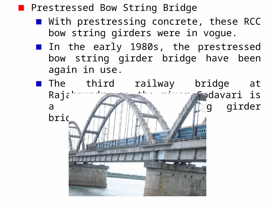
Piers may be solid, cellular, trestle, hammer head

Abutment is one terminal structure of a
bridge
In addition to weight of girder, abutment
have to support the embankment that
approach the bridge. It also protects the
embankment from scour
Abutments are also constructed by masonry,
concrete, reinforced concrete
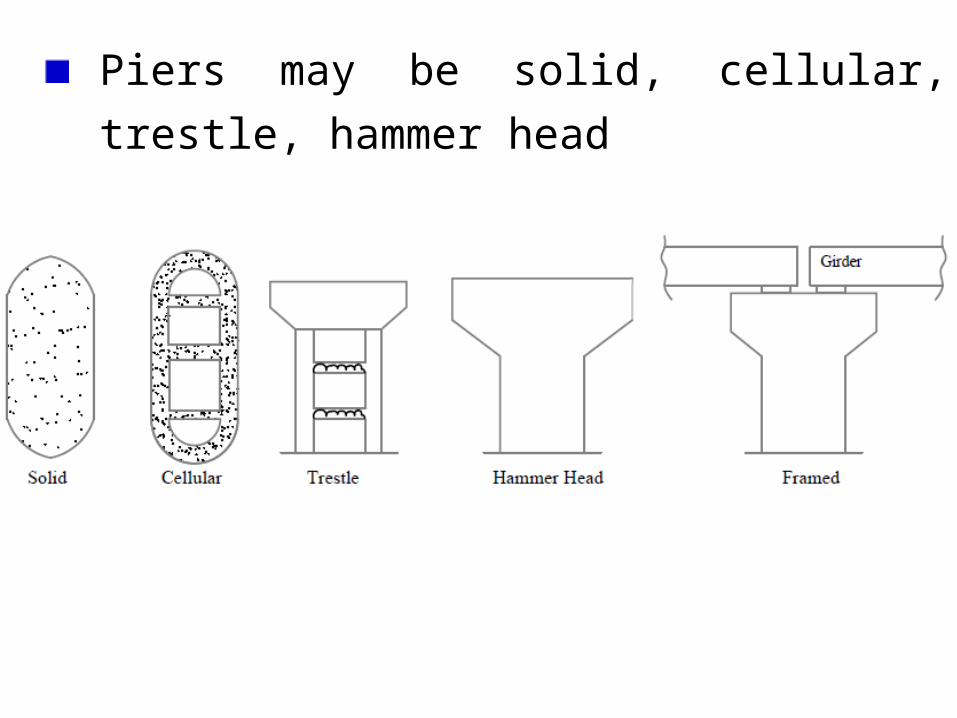
The abutment have to be designed for load from the bridge, earth pressure and live load on the embankment, adjacent to abutment

Wing walls may be solid wall or flying wing
walls
Immediately behind abutment i.e. just when
entering the bridge, an approach slab is
provided

Cause ways & Submergible Bridges
A cause way is a rigid raised platform in the bed.
When floods are of short duration i.e. 6 to 8 hours
once in a way, this is preferred.

Sometimes, pipes are provided to dispose of lean
flows in the river
A pucca bridge on the river allows traffic for most
of the time
During heavy floods, once in a way, the bridge will
be submerged. This is called submergible bridge.
Military Bridges
Generally temporary and sometimes permanent
Construction and dismantling in a short time
Two types
i. Fixed Bridge – Bailey Bridge
ii. Floating Bridge – Pontoon Bridge

Bailey Bridge
It is a steel bridge Steel panels, bracings, stringers will be brought
and will be assembled It will rest on grillage type of girders and cribs

Pontoon Bridge
It consists of a number of pneumatic pontoons or punts across the river at regular intervals
Trussed beams and transverse flanks are placed

Rigid Framed Bridge
It is an RCC continuous portal
It may be of slab type or may be a rib type
In the rib one, the slab will be connected continuously on the ribs

Bearings
Bearings transmit the loads from superstructure to pier
and also permits certain movements (longitudinal
movement and rotation)
For slabs, no special bearings are required – a kraft paper
under the slab and rounding of the edges will suffice

For submersible bridges, the slab have to be
anchored to the pier to resist uplift pressure
Bearings for Girders – Types
i. Plate Bearings
ii. Steel Roller Bearings
iii. RC Rocker Expansion Bearing
iv. Elastomaric Bearing
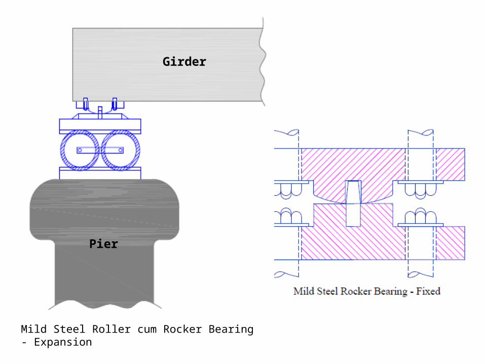
Girder
Pier
Mild Steel Roller cum Rocker Bearing - Expansion

Pier
Girder

Elastomeric Bearing

FOUNDATIONS
Foundations are important part of bridge
There are two types of foundations
i. Shallow Foundations
ii. Deep Foundations
Shallow foundations by open excavation
practicable up to maximum 5.0 m depth
For larger depths and for work under water shoring
with sheet piles or cofferdams to facilitate
excavation

If foundations on rock – a minimum depth of 0.6 m below
ground level – Rock to be benched – Dowel bars of 38 mm
diameter at 0.8 m to be provided to anchor

Deep foundations :
Pile Foundations – Fraction piles
Bearing Piles
Fraction pile transfer the load by skin friction i.e. by
friction along the embedded length

Piles also classified as Cast-in-situ and Precast
Piles may be timber, steel, concrete
For design of foundations
i. In a river the scour depth
ii. The grip length – minimum is 1/3 rd of scour
depth
iii. Soil pressures at the base
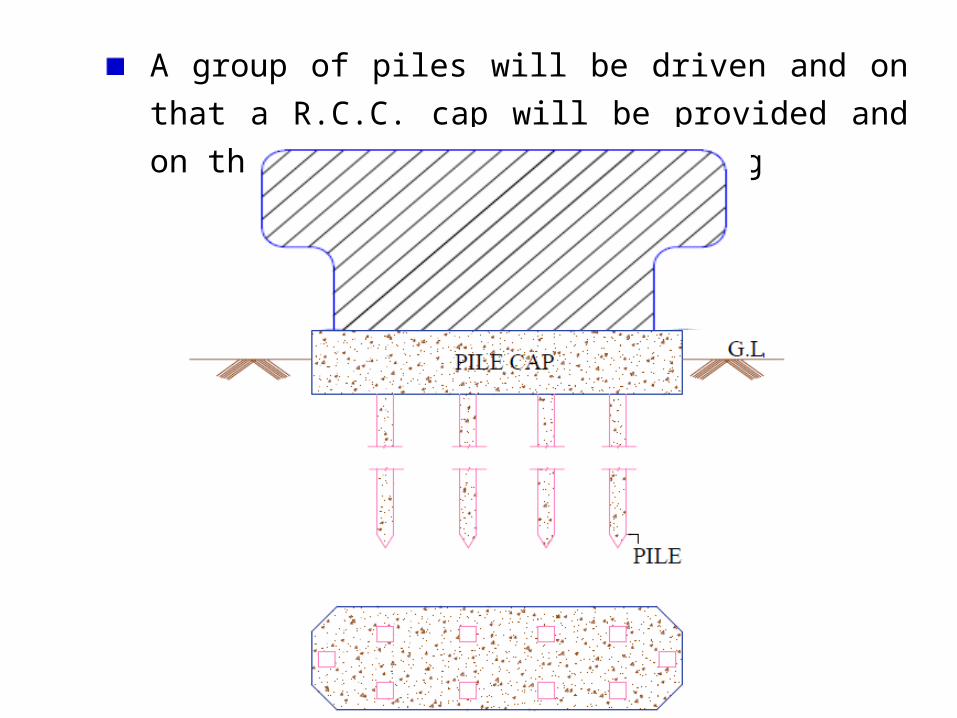
A group of piles will be driven and on that a R.C.C. cap
will be provided and on that the pier will be resting
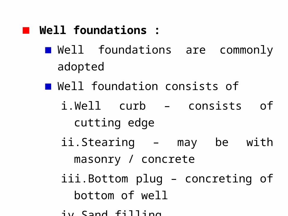
Well foundations :
Well foundations are commonly adopted
Well foundation consists of
i. Well curb – consists of cutting edge
ii. Stearing – may be with masonry / concrete
iii.Bottom plug – concreting of bottom of well
iv. Sand filling
v. Top plug – concreting of top
vi. Well cap

Well foundations

Shape of well may be
i. Circular
ii. Double D
iii.Square
iv. Rectangular

Construction of Bridges – Surveys - Requirements
Site survey at the bridge site (topographic surveys) to locate the bridge site and approaches. As far as possible a straight reach is possible
Sub-soil investigations to design the foundations
Traffic survey to fix the number of lanes and footpaths
Maximum discharge of the river to fix the length of the bridge
Maximum water level and free board (vertical clearance)
Related Documents