32 BRITISH DENTAL JOURNAL, VOLUME 187, NO. 1, JULY 10 1999 RESEARCH e nd o d o nt ics Root fractures reported as being caused by the compaction proce- dures of gutta-percha within the root canal by different techniques have been the subject of lengthy debate since their introduction to endodontic therapy. It has been speculated that excessive applica- tion of pressure during gutta-percha compaction process within the root canal could lead to root fractures. 1 There have been efforts to understand the nature and magni- tude of stresses distributed throughout the root during the appli- cation of different gutta-percha compaction techniques. These methods include mechanical testing systems, 2–4 strain gauge tech- niques, 5–6 and photoelastic modelling. 7 Reported mean spreader loads required to cause vertical root fractures during lateral com- paction in these investigations vary between 7–16 kg depending on many parameters such as tooth type, root canal flare, spreader design, root curvature, remaining dentine thickness after root canal preparation. 2–6 Recently finite element method (FEM) has been employed to esti- mate the stresses that occur during vertical and lateral compaction procedures. The reported values in these investigations appear to be in great contradiction. One group of investigators, eg Ricks- Williamson et al. 8 like Gimlin et al. 9 reported to have calculated maximum stresses of the order of 50–60 N/mm 2 in the apical or coronal sections of the root canal, whereas we 10 and Yaman et al., 11 Objective This study was designed to investigate the effect of certain pathological alterations of the dental structures (diminishing bone support, internal resorption, root perforation, periapical lesion) on stress distribution during root canal filling procedures by the warm vertical compaction technique. Design The computer stress analyses were done for a maxillary canine tooth model which was based on dimensions recovered from a human cadaveric maxilla scanned by CT. Methods The finite element method was used to calculate the stresses generated during root canal filling procedures by warm vertical compaction technique. Patterns of stress distribution associated with various alterations in dental structures were investigated. For this purpose 60 cases were simulated. The hypothetical force of 10 N is taken as a unit representation. For other magnitudes of applied force, the corresponding stresses would be scaled directly because the calculations were made for linear materials. Results and Conclusion It is found that, when diminishing bone support and internal resorption are concurrently simulated, a marked increase in stress magnitudes occur (maximum von Mises stress 5.37 N/mm 2 ). However, these values still remain much below the most frequently reported tensile strength of dentine (50–100 N/mm 2 ). If dentist’s handwork is transformed into equivalent edge tractions on gutta-percha, then stresses in dentine, even when they are corrected for 3-kg applied force, appear to remain below fracture strengths of this material. This result leads us to conclude that when warm vertical compaction technique is skilfully performed and inadvertent undue force is not applied, a premature root fracture in a large rooted maxillary anterior tooth with straight root canal anatomy is not likely to occur, even for the unfavourable conditions simulated in our model. This result, like all results derived from modelling applications, is of course contingent upon agreement between the way in which the clinical operations are performed and the way in which they are mirrored for computer representation. We believe that the approach described here avoids the spurious stresses that have been reported in similar investigations. 1 Associate Professor, Department of Endodontics, Hacettepe University, Faculty of Dentistry, Ankara, Turkey, currently on leave at Department of Operative Dentistry, Heinrich-Heine University, 40225 Düsseldorf, FRG 2 Professor, Department of Civil Engineering, Middle East Technical, University, 06531 Ankara, Turkey 3 Professor and Chairman, Department of Operative Dentistry, Heinrich-Heine University, 40225 Düsseldorf, FRG REFEREED PAPER Received 01.12.98; accepted 04.05.99 © British Dental Journal 1999; 187: 32–37 Additional studies on the distribution of stresses during vertical compaction of gutta-percha in the root canal C. Telli, 1 P. Gülkan, 2 and W. Raab, 3 Table 1 Material properties 1 Modulus of elasticity Poisson’s ratio N/mm 2 Enamel 14 8.41 x 10 4 0.300 Dentine 15 2.00 x 10 4 0.310 Periodontal ligament 16 5.00 x 10 1 0.490 Alveolar bone 17 1.40 x 10 4 0.150 Gutta-percha (cold) 18 3.00 x 10 2 0.485 Gutta-percha (warm) 18 3.00 x 10 0 0.485 Special element 1.50 x 10 0 0.499 1 Every material, including biological ones, possesses certain intrinsic mechanical properties that are used in performing stress analyses of situations in which they are involved. One of these is a measure of their stiffness, or resistance to becom- ing deformed. This property is expressed through the elastic modulus, also called Young’s modulus, which, in the case of a linear material, is the ratio of the stress (force per unit area) to the strain (change of length per unit length). When stresses and strains are directly proportional, the material is said to be linear. (For every biological material this may not be the case.) The word ‘modulus’ means ‘a small measure’ in Latin. The other particular property characterising every material is the so-called Poisson’s ratio. This is a dimensionless number that characterises how much a given material will deform in a direction perpendicular to the direction in which it is loaded. For example, if a piece of putty is shaped like a cylindrical object, and then stretched, ie made longer, its diameter will shrink. Conversely, if the putty is placed inside a rigid- walled container, and then pressed from its open end, it will press against the walls of the container because it will want to expand laterally. For most common materials this ratio lies in the range 0.1–0.45

Welcome message from author
This document is posted to help you gain knowledge. Please leave a comment to let me know what you think about it! Share it to your friends and learn new things together.
Transcript
32 BRITISH DENTAL JOURNAL, VOLUME 187, NO. 1, JULY 10 1999
RESEARCH endodontics
Root fractures reported as being caused by the compaction proce-dures of gutta-percha within the root canal by different techniqueshave been the subject of lengthy debate since their introduction toendodontic therapy. It has been speculated that excessive applica-tion of pressure during gutta-percha compaction process within theroot canal could lead to root fractures.1
There have been efforts to understand the nature and magni-tude of stresses distributed throughout the root during the appli-cation of different gutta-percha compaction techniques. Thesemethods include mechanical testing systems,2–4 strain gauge tech-niques,5–6 and photoelastic modelling.7 Reported mean spreaderloads required to cause vertical root fractures during lateral com-paction in these investigations vary between 7–16 kg dependingon many parameters such as tooth type, root canal flare, spreaderdesign, root curvature, remaining dentine thickness after rootcanal preparation.2–6
Recently finite element method (FEM) has been employed to esti-mate the stresses that occur during vertical and lateral compactionprocedures. The reported values in these investigations appear to bein great contradiction. One group of investigators, eg Ricks-Williamson et al.8 like Gimlin et al.9 reported to have calculatedmaximum stresses of the order of 50–60 N/mm2 in the apical orcoronal sections of the root canal, whereas we10 and Yaman et al.,11
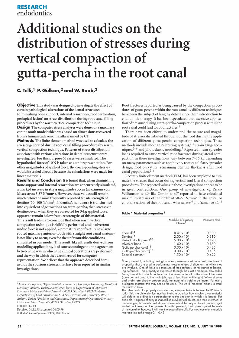
Objective This study was designed to investigate the effect ofcertain pathological alterations of the dental structures(diminishing bone support, internal resorption, root perforation,periapical lesion) on stress distribution during root canal fillingprocedures by the warm vertical compaction technique.Design The computer stress analyses were done for a maxillarycanine tooth model which was based on dimensions recoveredfrom a human cadaveric maxilla scanned by CT.Methods The finite element method was used to calculate thestresses generated during root canal filling procedures by warmvertical compaction technique. Patterns of stress distributionassociated with various alterations in dental structures wereinvestigated. For this purpose 60 cases were simulated. Thehypothetical force of 10 N is taken as a unit representation. Forother magnitudes of applied force, the corresponding stresseswould be scaled directly because the calculations were made forlinear materials.Results and Conclusion It is found that, when diminishingbone support and internal resorption are concurrently simulated,a marked increase in stress magnitudes occur (maximum vonMises stress 5.37 N/mm2). However, these values still remainmuch below the most frequently reported tensile strength ofdentine (50–100 N/mm2). If dentist’s handwork is transformedinto equivalent edge tractions on gutta-percha, then stresses indentine, even when they are corrected for 3-kg applied force,appear to remain below fracture strengths of this material.This result leads us to conclude that when warm verticalcompaction technique is skilfully performed and inadvertentundue force is not applied, a premature root fracture in a largerooted maxillary anterior tooth with straight root canal anatomyis not likely to occur, even for the unfavourable conditionssimulated in our model. This result, like all results derived frommodelling applications, is of course contingent upon agreementbetween the way in which the clinical operations are performedand the way in which they are mirrored for computerrepresentation. We believe that the approach described hereavoids the spurious stresses that have been reported in similarinvestigations.
1Associate Professor, Department of Endodontics, Hacettepe University, Faculty ofDentistry, Ankara, Turkey, currently on leave at Department of OperativeDentistry, Heinrich-Heine University, 40225 Düsseldorf, FRG 2Professor,Department of Civil Engineering, Middle East Technical, University, 06531Ankara, Turkey 3Professor and Chairman, Department of Operative Dentistry,Heinrich-Heine University, 40225 Düsseldorf, FRGREFEREED PAPER
Received 01.12.98; accepted 04.05.99© British Dental Journal 1999; 187: 32–37
Additional studies on thedistribution of stresses duringvertical compaction of gutta-percha in the root canalC. Telli,1 P. Gülkan,2 and W. Raab,3
Table 1 Material properties1
Modulus of elasticity Poisson’s ratioN/mm2
Enamel14 8.41 x 10⁴ 0.300Dentine15 2.00 x 10⁴ 0.310Periodontal ligament16 5.00 x 101 0.490Alveolar bone17 1.40 x 10⁴ 0.150Gutta-percha (cold)18 3.00 x 10² 0.485Gutta-percha (warm)18 3.00 x 100 0.485Special element 1.50 x 100 0.499
1Every material, including biological ones, possesses certain intrinsic mechanicalproperties that are used in performing stress analyses of situations in which theyare involved. One of these is a measure of their stiffness, or resistance to becom-ing deformed. This property is expressed through the elastic modulus, also calledYoung’s modulus, which, in the case of a linear material, is the ratio of the stress(force per unit area) to the strain (change of length per unit length). When stressesand strains are directly proportional, the material is said to be linear. (For everybiological material this may not be the case.) The word ‘modulus’ means ‘a smallmeasure’ in Latin.The other particular property characterising every material is the so-called Poisson’sratio. This is a dimensionless number that characterises how much a given materialwill deform in a direction perpendicular to the direction in which it is loaded. Forexample, if a piece of putty is shaped like a cylindrical object, and then stretched, iemade longer, its diameter will shrink. Conversely, if the putty is placed inside a rigid-walled container, and then pressed from its open end, it will press against the wallsof the container because it will want to expand laterally. For most common materialsthis ratio lies in the range 0.1–0.45
BRITISH DENTAL JOURNAL, VOLUME 187, NO. 1, JULY 10 1999 33
RESEARCH endodontics
following different modelling procedures, have calculated maxi-mum stresses which are about an order of magnitude smaller ofthat, even when corrections are introduced to take into account thedifferences of the applied force. The orders of magnitude for thestresses reported in References 8 and 9 are so high as to cause frac-
ture in most materials encountered in ordinary engineering prac-tice. These values are even above some of the most frequentlyreported tensile strength for dentine (50–100 N/mm2).12–13
In our earlier work we have calculated the stresses generated dur-ing lateral and vertical compaction of gutta-percha within the root
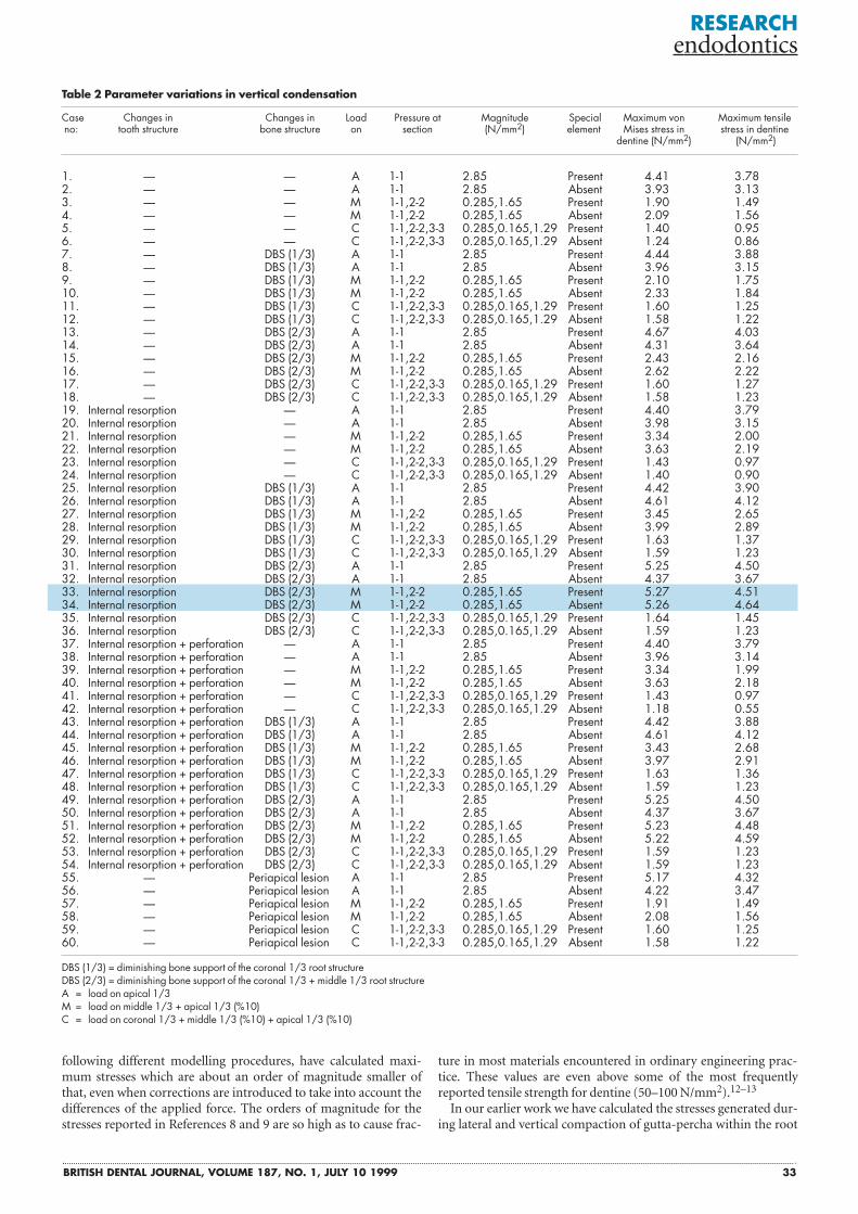
Table 2 Parameter variations in vertical condensation
Case Changes in Changes in Load Pressure at Magnitude Special Maximum von Maximum tensileno: tooth structure bone structure on section (N/mm2) element Mises stress in stress in dentine
dentine (N/mm2) (N/mm2)
1. — — A 1-1 2.85 Present 4.41 3.782. — — A 1-1 2.85 Absent 3.93 3.133. — — M 1-1,2-2 0.285,1.65 Present 1.90 1.494. — — M 1-1,2-2 0.285,1.65 Absent 2.09 1.565. — — C 1-1,2-2,3-3 0.285,0.165,1.29 Present 1.40 0.956. — — C 1-1,2-2,3-3 0.285,0.165,1.29 Absent 1.24 0.867. — DBS (1/3) A 1-1 2.85 Present 4.44 3.888. — DBS (1/3) A 1-1 2.85 Absent 3.96 3.159. — DBS (1/3) M 1-1,2-2 0.285,1.65 Present 2.10 1.7510. — DBS (1/3) M 1-1,2-2 0.285,1.65 Absent 2.33 1.8411. — DBS (1/3) C 1-1,2-2,3-3 0.285,0.165,1.29 Present 1.60 1.2512. — DBS (1/3) C 1-1,2-2,3-3 0.285,0.165,1.29 Absent 1.58 1.2213. — DBS (2/3) A 1-1 2.85 Present 4.67 4.0314. — DBS (2/3) A 1-1 2.85 Absent 4.31 3.6415. — DBS (2/3) M 1-1,2-2 0.285,1.65 Present 2.43 2.1616. — DBS (2/3) M 1-1,2-2 0.285,1.65 Absent 2.62 2.2217. — DBS (2/3) C 1-1,2-2,3-3 0.285,0.165,1.29 Present 1.60 1.2718. — DBS (2/3) C 1-1,2-2,3-3 0.285,0.165,1.29 Absent 1.58 1.2319. Internal resorption — A 1-1 2.85 Present 4.40 3.7920. Internal resorption — A 1-1 2.85 Absent 3.98 3.1521. Internal resorption — M 1-1,2-2 0.285,1.65 Present 3.34 2.0022. Internal resorption — M 1-1,2-2 0.285,1.65 Absent 3.63 2.1923. Internal resorption — C 1-1,2-2,3-3 0.285,0.165,1.29 Present 1.43 0.9724. Internal resorption — C 1-1,2-2,3-3 0.285,0.165,1.29 Absent 1.40 0.9025. Internal resorption DBS (1/3) A 1-1 2.85 Present 4.42 3.9026. Internal resorption DBS (1/3) A 1-1 2.85 Absent 4.61 4.1227. Internal resorption DBS (1/3) M 1-1,2-2 0.285,1.65 Present 3.45 2.6528. Internal resorption DBS (1/3) M 1-1,2-2 0.285,1.65 Absent 3.99 2.8929. Internal resorption DBS (1/3) C 1-1,2-2,3-3 0.285,0.165,1.29 Present 1.63 1.3730. Internal resorption DBS (1/3) C 1-1,2-2,3-3 0.285,0.165,1.29 Absent 1.59 1.2331. Internal resorption DBS (2/3) A 1-1 2.85 Present 5.25 4.5032. Internal resorption DBS (2/3) A 1-1 2.85 Absent 4.37 3.6733. Internal resorption DBS (2/3) M 1-1,2-2 0.285,1.65 Present 5.27 4.5134. Internal resorption DBS (2/3) M 1-1,2-2 0.285,1.65 Absent 5.26 4.6435. Internal resorption DBS (2/3) C 1-1,2-2,3-3 0.285,0.165,1.29 Present 1.64 1.4536. Internal resorption DBS (2/3) C 1-1,2-2,3-3 0.285,0.165,1.29 Absent 1.59 1.2337. Internal resorption + perforation — A 1-1 2.85 Present 4.40 3.7938. Internal resorption + perforation — A 1-1 2.85 Absent 3.96 3.1439. Internal resorption + perforation — M 1-1,2-2 0.285,1.65 Present 3.34 1.9940. Internal resorption + perforation — M 1-1,2-2 0.285,1.65 Absent 3.63 2.1841. Internal resorption + perforation — C 1-1,2-2,3-3 0.285,0.165,1.29 Present 1.43 0.9742. Internal resorption + perforation — C 1-1,2-2,3-3 0.285,0.165,1.29 Absent 1.18 0.5543. Internal resorption + perforation DBS (1/3) A 1-1 2.85 Present 4.42 3.8844. Internal resorption + perforation DBS (1/3) A 1-1 2.85 Absent 4.61 4.1245. Internal resorption + perforation DBS (1/3) M 1-1,2-2 0.285,1.65 Present 3.43 2.6846. Internal resorption + perforation DBS (1/3) M 1-1,2-2 0.285,1.65 Absent 3.97 2.9147. Internal resorption + perforation DBS (1/3) C 1-1,2-2,3-3 0.285,0.165,1.29 Present 1.63 1.3648. Internal resorption + perforation DBS (1/3) C 1-1,2-2,3-3 0.285,0.165,1.29 Absent 1.59 1.2349. Internal resorption + perforation DBS (2/3) A 1-1 2.85 Present 5.25 4.5050. Internal resorption + perforation DBS (2/3) A 1-1 2.85 Absent 4.37 3.6751. Internal resorption + perforation DBS (2/3) M 1-1,2-2 0.285,1.65 Present 5.23 4.4852. Internal resorption + perforation DBS (2/3) M 1-1,2-2 0.285,1.65 Absent 5.22 4.5953. Internal resorption + perforation DBS (2/3) C 1-1,2-2,3-3 0.285,0.165,1.29 Present 1.59 1.2354. Internal resorption + perforation DBS (2/3) C 1-1,2-2,3-3 0.285,0.165,1.29 Absent 1.59 1.2355. — Periapical lesion A 1-1 2.85 Present 5.17 4.3256. — Periapical lesion A 1-1 2.85 Absent 4.22 3.4757. — Periapical lesion M 1-1,2-2 0.285,1.65 Present 1.91 1.4958. — Periapical lesion M 1-1,2-2 0.285,1.65 Absent 2.08 1.5659. — Periapical lesion C 1-1,2-2,3-3 0.285,0.165,1.29 Present 1.60 1.2560. — Periapical lesion C 1-1,2-2,3-3 0.285,0.165,1.29 Absent 1.58 1.22
DBS (1/3) = diminishing bone support of the coronal 1/3 root structureDBS (2/3) = diminishing bone support of the coronal 1/3 + middle 1/3 root structureA = load on apical 1/3M = load on middle 1/3 + apical 1/3 (%10)C = load on coronal 1/3 + middle 1/3 (%10) + apical 1/3 (%10)
34 BRITISH DENTAL JOURNAL, VOLUME 187, NO. 1, JULY 10 1999
canal on a 3-Dimensional (3D) maxillary canine tooth model whichwas crafted by using the dimensions of computer tomographicscans of a cadaveric maxilla.10 In the present study, certain patho-logical conditions which cause some degree of weakness of the den-tal structures will be investigated. The objective for this attempt is toinvestigate whether these parametrically varied conditions may leadto premature root fractures under vertical compaction forces.
Materials and methods
The model The standard body for which the stress analysis was performed, aswell as the parametric modifications designed for this study isshown in figure 1. This model represents a maxillary canine toothand its adjacent supporting structures. The material properties ofthe components in the model were defined based on previous stud-ies as given in Table 1.14–18 The tooth was represented primarily asan assemblage of 8-noded solid brick elements. The model in fig-ure1 has 3,680 nodes and 2,514 elements. Details of the modellingprocedure were described in a previous article.10 The fineness of themodel was primarily governed by the scans obtained from a cadev-eric maxilla. In finite element work, finer subdivisions generallylead to more accurate results.
The basic model has been kept unchanged because the primaryobjective here is to ascertain whether the systematic parameter vari-ations that will be introduced in it will in fact lead to stresses thatmight test the capacity of the dentine. The previous conclusion hadbeen that undetected imperfections in the tooth structure or otherirregularities for which no provision was made during the model-ling phase and the misapplication of the technique (ie extreme lev-ering action done by spreader, or an inadvertent transmission ofundue forces on dentine through the tip of a plugger or spreader)were the likely culprits in causing the root fractures. It is now time totest that hypothesis.10
Pathological changes in dental structures simulated in thisstudy are summarised in Table 2, whereas elements used for rep-
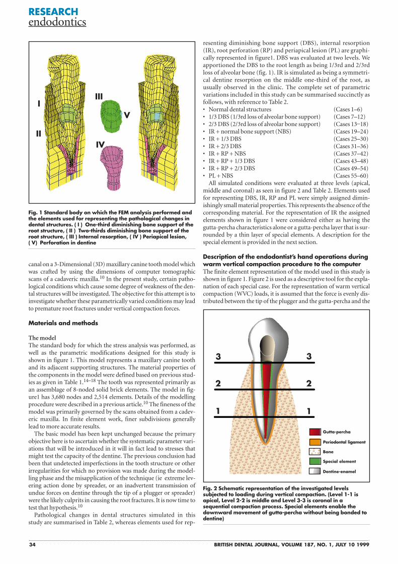
resenting diminishing bone support (DBS), internal resorption(IR), root perforation (RP) and periapical lesion (PL) are graphi-cally represented in figure1. DBS was evaluated at two levels. Weapportioned the DBS to the root length as being 1/3rd and 2/3rdloss of alveolar bone (fig. 1). IR is simulated as being a symmetri-cal dentine resorption on the middle one-third of the root, asusually observed in the clinic. The complete set of parametricvariations included in this study can be summarised succinctly asfollows, with reference to Table 2. • Normal dental structures (Cases 1–6)• 1/3 DBS (1/3rd loss of alveolar bone support) (Cases 7–12)• 2/3 DBS (2/3rd loss of alveolar bone support) (Cases 13–18)• IR + normal bone support (NBS) (Cases 19–24)• IR + 1/3 DBS (Cases 25–30)• IR + 2/3 DBS (Cases 31–36)• IR + RP + NBS (Cases 37–42)• IR + RP + 1/3 DBS (Cases 43–48)• IR + RP + 2/3 DBS (Cases 49–54)• PL + NBS (Cases 55–60)
All simulated conditions were evaluated at three levels (apical,middle and coronal) as seen in figure 2 and Table 2. Elements usedfor representing DBS, IR, RP and PL were simply assigned dimin-ishingly small material properties. This represents the absence of thecorresponding material. For the representation of IR the assignedelements shown in figure 1 were considered either as having thegutta-percha characteristics alone or a gutta-percha layer that is sur-rounded by a thin layer of special elements. A description for thespecial element is provided in the next section.
Description of the endodontist’s hand operations duringwarm vertical compaction procedure to the computer The finite element representation of the model used in this study isshown in figure 1. Figure 2 is used as a descriptive tool for the expla-nation of each special case. For the representation of warm verticalcompaction (WVC) loads, it is assumed that the force is evenly dis-tributed between the tip of the plugger and the gutta-percha and the
RESEARCH endodontics
Fig. 1 Standard body on which the FEM analysis performed andthe elements used for representing the pathological changes indental structures. ( I ) One-third diminishing bone support of theroot structure, ( II ) Two-thirds diminishing bone support of theroot structure, ( III ) Internal resorption, ( IV ) Periapical lesion, ( V) Perforation in dentine
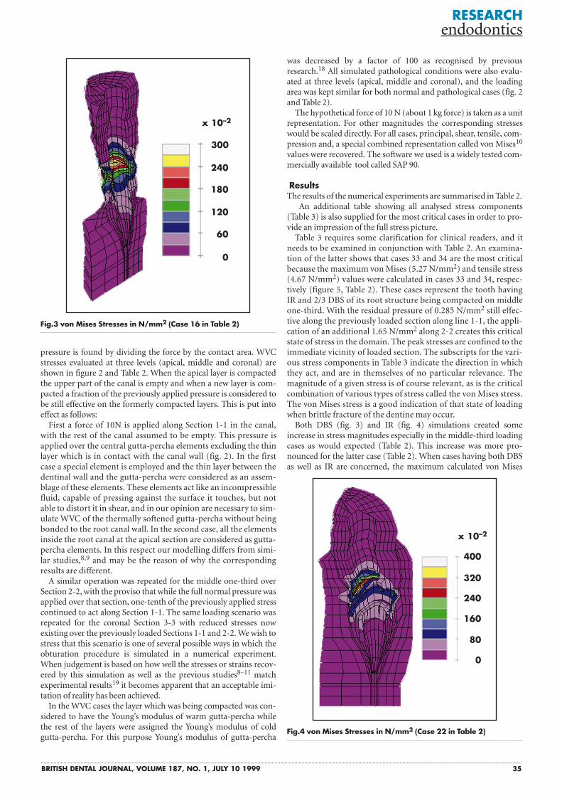
Fig. 2 Schematic representation of the investigated levelssubjected to loading during vertical compaction. (Level 1-1 isapical, Level 2-2 is middle and Level 3-3 is coronal in asequential compaction process. Special elements enable thedownward movement of gutta-percha without being bonded todentine)
IIII
IV
V
II
3
22
1 1
3
Gutta-percha
Bone
Special element
Dentine-enamel
Periodontal ligament
BRITISH DENTAL JOURNAL, VOLUME 187, NO. 1, JULY 10 1999 35
pressure is found by dividing the force by the contact area. WVCstresses evaluated at three levels (apical, middle and coronal) areshown in figure 2 and Table 2. When the apical layer is compactedthe upper part of the canal is empty and when a new layer is com-pacted a fraction of the previously applied pressure is considered tobe still effective on the formerly compacted layers. This is put intoeffect as follows:
First a force of 10N is applied along Section 1-1 in the canal,with the rest of the canal assumed to be empty. This pressure isapplied over the central gutta-percha elements excluding the thinlayer which is in contact with the canal wall (fig. 2). In the firstcase a special element is employed and the thin layer between thedentinal wall and the gutta-percha were considered as an assem-blage of these elements. These elements act like an incompressiblefluid, capable of pressing against the surface it touches, but notable to distort it in shear, and in our opinion are necessary to sim-ulate WVC of the thermally softened gutta-percha without beingbonded to the root canal wall. In the second case, all the elementsinside the root canal at the apical section are considered as gutta-percha elements. In this respect our modelling differs from simi-lar studies,8,9 and may be the reason of why the correspondingresults are different.
A similar operation was repeated for the middle one-third overSection 2-2, with the proviso that while the full normal pressure wasapplied over that section, one-tenth of the previously applied stresscontinued to act along Section 1-1. The same loading scenario wasrepeated for the coronal Section 3-3 with reduced stresses nowexisting over the previously loaded Sections 1-1 and 2-2. We wish tostress that this scenario is one of several possible ways in which theobturation procedure is simulated in a numerical experiment.When judgement is based on how well the stresses or strains recov-ered by this simulation as well as the previous studies8–11 matchexperimental results19 it becomes apparent that an acceptable imi-tation of reality has been achieved.
In the WVC cases the layer which was being compacted was con-sidered to have the Young’s modulus of warm gutta-percha whilethe rest of the layers were assigned the Young’s modulus of coldgutta-percha. For this purpose Young’s modulus of gutta-percha
was decreased by a factor of 100 as recognised by previousresearch.18 All simulated pathological conditions were also evalu-ated at three levels (apical, middle and coronal), and the loadingarea was kept similar for both normal and pathological cases (fig. 2and Table 2).
The hypothetical force of 10 N (about 1 kg force) is taken as a unitrepresentation. For other magnitudes the corresponding stresseswould be scaled directly. For all cases, principal, shear, tensile, com-pression and, a special combined representation called von Mises10
values were recovered. The software we used is a widely tested com-mercially available tool called SAP 90.
ResultsThe results of the numerical experiments are summarised in Table 2.
An additional table showing all analysed stress components(Table 3) is also supplied for the most critical cases in order to pro-vide an impression of the full stress picture.
Table 3 requires some clarification for clinical readers, and itneeds to be examined in conjunction with Table 2. An examina-tion of the latter shows that cases 33 and 34 are the most criticalbecause the maximum von Mises (5.27 N/mm2) and tensile stress(4.67 N/mm2) values were calculated in cases 33 and 34, respec-tively (figure 5, Table 2). These cases represent the tooth havingIR and 2/3 DBS of its root structure being compacted on middleone-third. With the residual pressure of 0.285 N/mm2 still effec-tive along the previously loaded section along line 1-1, the appli-cation of an additional 1.65 N/mm2 along 2-2 creates this criticalstate of stress in the domain. The peak stresses are confined to theimmediate vicinity of loaded section. The subscripts for the vari-ous stress components in Table 3 indicate the direction in whichthey act, and are in themselves of no particular relevance. Themagnitude of a given stress is of course relevant, as is the criticalcombination of various types of stress called the von Mises stress.The von Mises stress is a good indication of that state of loadingwhen brittle fracture of the dentine may occur.
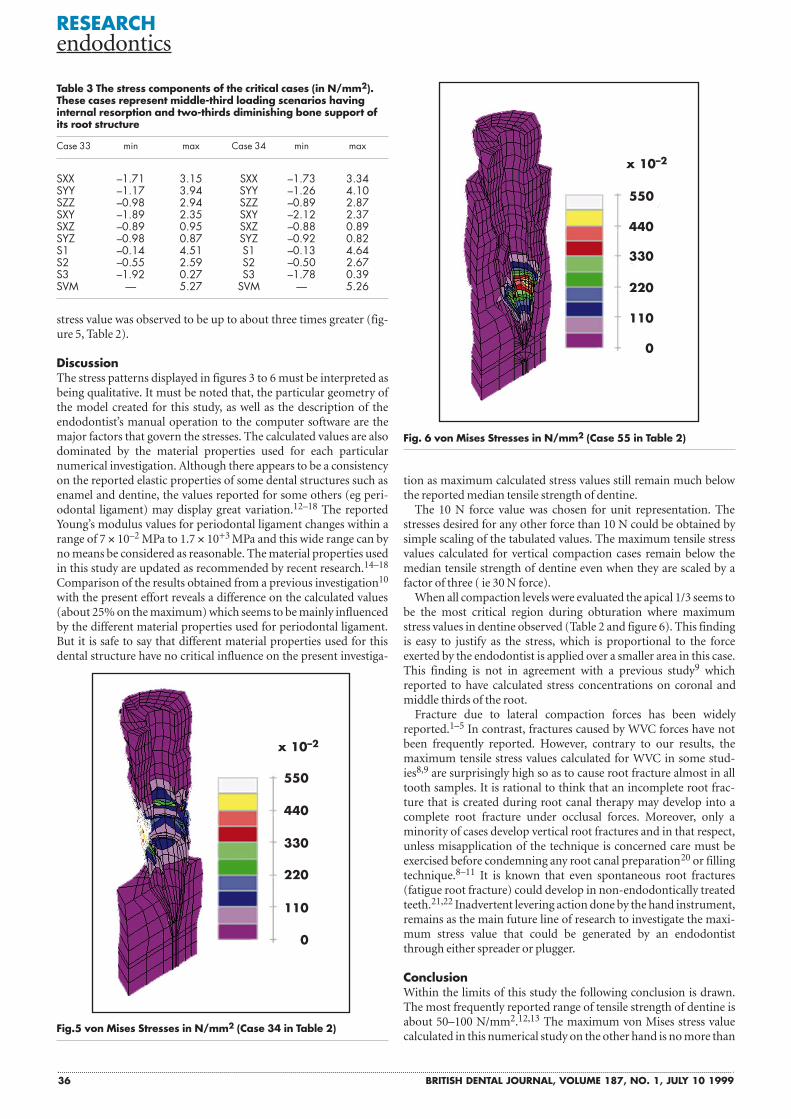
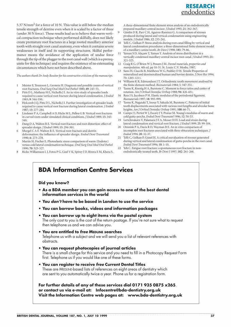
Both DBS (fig. 3) and IR (fig. 4) simulations created someincrease in stress magnitudes especially in the middle-third loadingcases as would expected (Table 2). This increase was more pro-nounced for the latter case (Table 2). When cases having both DBSas well as IR are concerned, the maximum calculated von Mises
RESEARCH endodontics
Fig.3 von Mises Stresses in N/mm2 (Case 16 in Table 2)
Fig.4 von Mises Stresses in N/mm2 (Case 22 in Table 2)
300
x 10–2
x 10–2
240
400
320
240
160
80
0
180
120
60
0
36 BRITISH DENTAL JOURNAL, VOLUME 187, NO. 1, JULY 10 1999
stress value was observed to be up to about three times greater (fig-ure 5, Table 2).
DiscussionThe stress patterns displayed in figures 3 to 6 must be interpreted asbeing qualitative. It must be noted that, the particular geometry ofthe model created for this study, as well as the description of theendodontist’s manual operation to the computer software are themajor factors that govern the stresses. The calculated values are alsodominated by the material properties used for each particularnumerical investigation. Although there appears to be a consistencyon the reported elastic properties of some dental structures such asenamel and dentine, the values reported for some others (eg peri-odontal ligament) may display great variation.12–18 The reportedYoung’s modulus values for periodontal ligament changes within arange of 7 10–2 MPa to 1.7 10+3 MPa and this wide range can byno means be considered as reasonable. The material properties usedin this study are updated as recommended by recent research.14–18
Comparison of the results obtained from a previous investigation10
with the present effort reveals a difference on the calculated values(about 25% on the maximum) which seems to be mainly influencedby the different material properties used for periodontal ligament.But it is safe to say that different material properties used for thisdental structure have no critical influence on the present investiga-
tion as maximum calculated stress values still remain much belowthe reported median tensile strength of dentine.
The 10 N force value was chosen for unit representation. Thestresses desired for any other force than 10 N could be obtained bysimple scaling of the tabulated values. The maximum tensile stressvalues calculated for vertical compaction cases remain below themedian tensile strength of dentine even when they are scaled by afactor of three ( ie 30 N force).
When all compaction levels were evaluated the apical 1/3 seems tobe the most critical region during obturation where maximumstress values in dentine observed (Table 2 and figure 6). This findingis easy to justify as the stress, which is proportional to the forceexerted by the endodontist is applied over a smaller area in this case.This finding is not in agreement with a previous study9 whichreported to have calculated stress concentrations on coronal andmiddle thirds of the root.
Fracture due to lateral compaction forces has been widelyreported.1–5 In contrast, fractures caused by WVC forces have notbeen frequently reported. However, contrary to our results, themaximum tensile stress values calculated for WVC in some stud-ies8,9 are surprisingly high so as to cause root fracture almost in alltooth samples. It is rational to think that an incomplete root frac-ture that is created during root canal therapy may develop into acomplete root fracture under occlusal forces. Moreover, only aminority of cases develop vertical root fractures and in that respect,unless misapplication of the technique is concerned care must beexercised before condemning any root canal preparation20 or fillingtechnique.8–11 It is known that even spontaneous root fractures(fatigue root fracture) could develop in non-endodontically treatedteeth.21,22 Inadvertent levering action done by the hand instrument,remains as the main future line of research to investigate the maxi-mum stress value that could be generated by an endodontistthrough either spreader or plugger.
ConclusionWithin the limits of this study the following conclusion is drawn.The most frequently reported range of tensile strength of dentine isabout 50–100 N/mm2.12,13 The maximum von Mises stress valuecalculated in this numerical study on the other hand is no more than
RESEARCH endodontics
Table 3 The stress components of the critical cases (in N/mm2).These cases represent middle-third loading scenarios havinginternal resorption and two-thirds diminishing bone support ofits root structure
Case 33 min max Case 34 min max
SXX –1.71 3.15 SXX –1.73 3.34SYY –1.17 3.94 SYY –1.26 4.10SZZ –0.98 2.94 SZZ –0.89 2.87SXY –1.89 2.35 SXY –2.12 2.37SXZ –0.89 0.95 SXZ –0.88 0.89SYZ –0.98 0.87 SYZ –0.92 0.82S1 –0.14 4.51 S1 –0.13 4.64S2 –0.55 2.59 S2 –0.50 2.67S3 –1.92 0.27 S3 –1.78 0.39SVM — 5.27 SVM — 5.26
Fig. 6 von Mises Stresses in N/mm2 (Case 55 in Table 2)
Fig.5 von Mises Stresses in N/mm2 (Case 34 in Table 2)
550
440
330
220
110
0
x 10–2
550
440
330
220
110
0
x 10–2
BRITISH DENTAL JOURNAL, VOLUME 187, NO. 1, JULY 10 1999 37
5.37 N/mm2 for a force of 10 N. This value is still below the mediantensile strength of dentine even when it is scaled by a factor of three(under 30 N force). These results lead us to believe that warm verti-cal compaction technique when performed skilfully, does not likelycreate premature root fractures in a large rooted maxillary anteriortooth with straight root canal anatomy, even when it contains severeweaknesses in itself and its supporting structures. Skilful perfor-mance means the avoidance of the application of undue forcethrough the tip of the plugger to the root canal wall (which is a prereq-uisite for this technique) and requires the existence of no extenuatingcircumstances which have not been described above.
The authors thank Dr Andy Rossiter for his constructive criticism of the manuscript.
1 Meister F, Tennyson L, Gerstein H. Diagnosis and possible causes of verticalroot fractures. Oral Surg Oral Med Oral Pathol 1980; 49: 243-53.
2 Pitts D L, Matheny H E, Nicholls J I. An in vitro study of spreader loadsrequired to cause vertical root fracture during lateral condensation. J Endod1983; 9: 544-550.
3 Holcomb J Q, Pitts D L, Nicholls J I. Further investigation of spreader loadsrequired to cause vertical root fracture during lateral condensation. J Endod1987; 13: 277-284.
4 Lindauer P A, Campbell A D, Hicks M L, Pelleu G B. Vertical root fracturesin curved roots under simulated clinical conditions. J Endod 1989; 15: 345-349.
5 Dang D A, Walton R E. Vertical root fracture and root distortion: effect ofspreader design. J Endod 1989; 15: 294-301.
6 Murgel C A F, Walton R E. Vertical root fracture and dentindeformation: the influence of spreader design. Endod Dent Traumatol1990; 6: 273-278.
7 Martin H, Fischer E. Photoelastic stress comparison of warm (Endotec)versus cold lateral condensation technique. Oral Surg Oral Med Oral Pathol1990; 70: 325-327.
8 Ricks-Williamson L J, Fotos P G, Goel V K, Spivey J D, Rivera E M, Khera S.
RESEARCH endodontics
A three-dimensional finite element stress analysis of an endodonticallyprepared maxillary central incisor. J Endod 1995; 21: 362-367.
9 Gimlin D R, Parr C H, Aguirre-Ramirez G. A comparison of stressesproduced during lateral and vertical condensation using engineeringmodels. J Endod 1986; 12: 235-241.
10 Telli C, Gülkan P. Stress analysis during root canal filling by vertical andlateral condensation procedures: a three-dimensional finite element modelof a maxillary canine tooth. Br Dent J 1998; 185: 79-86.
11 Yaman S D, Alaçam T, Yaman Y. Analysis of stress distribution in avertically condensed maxillary central incisor root canal. J Endod 1995; 21:321-325.
12 Craig R G, O’Brien W J, Powers J M. Dental materials, properties andmanipulation. 4th ed, pp 10-31. St. Louis: C.V. Mosby, 1987.
13 Sano H, Ciucchi B, Matthews W G, Pashley D H. Tensile Properties ofmineralized and demineralized human and bovine dentin. J Dent Res 1994;73: 1205-1211.
14 Williams K R, Edmundson J T. Orthodontic tooth movement analysed bythe finite element method. Biomaterials 1984; 5: 347-351.
15 Tanne K, Koenig H A, Burstone C. Moment to force ratios and center ofrotation. Am J Orthod Dentofac Orthop 1988; 94: 426-431.
16 Rees J S, Jacobsen P H. Elastic modulus of the periodontal ligament.Biomaterials 1997; 18: 995-999.
17 Tanne K, Nagataki T, Inoue Y, Sakuda M, Burstone C. Patterns of initialtooth displacements associated with various root lengths and alveolar boneheights. Am J Orthod Dentofac Orthop 1991; 100: 66-71.
18 Camps J J, Pertot W J, Escavy J Y, Pravaz M. Young’s modulus of warm andcold gutta-percha. Endod Dent Traumatol 1996; 12: 50-53.
19 Lertchirakarn V, Palamara J E A, Messer H H. Load and strain duringlateral condensation and vertical root fracture. J Endod 1999; 25: 99-104.
20 Omnink P A, Davis R D, Wayman B E. An in vitro comparison ofincomplete root fractures associated with three obturation techniques. JEndod 1994; 20: 32-37.
21 Telli C, Gülkan P, Günel H. A critical reevaluation of stresses generatedduring vertical and lateral condensation of gutta-percha in the root canal.Endod Dent Traumatol 1994; 10: 1-10.
22 Yeh C. Fatigue root fracture: a spontaneous root fracture in non-endodontically treated teeth. Br Dent J 1997; 182: 261-266.
Did you know?
• As a BDA member you can gain access to one of the best dental information services in the world
• You don’t have to be based in London to use the service
• You can borrow books, videos and information packages
• You can borrow up to eight items via the postal systemThe only cost to you is the cost of the return postage. If you’re not sure what to request then telephone us and we can advise you.
• You are entitled to free MEDLINE searchesTelephone us with a subject and we will send you a list of relevant references with abstracts.
• You can request photocopies of journal articlesThere is a small charge for this service and you need to fill in a Photocopy Request Form first. Telephone us if you would like one of these forms.
• You can register to receive free Current Dental TitlesThese are MEDLINE-based lists of references on eight areas of dentistry which are sent to you automatically twice a year. Phone us for a registration form.
For further details of any of these services dial 0171 935 0875 x265.or contact us via e-mail at: [email protected] the Information Centre web pages at: www.bda-dentistry.org.uk
BDA Information Centre Services
Related Documents