Addition Circuits Shmuel Wimer Bar Ilan University, Engineering Faculty Technion, EE Faculty Nov 2012 1

Welcome message from author
This document is posted to help you gain knowledge. Please leave a comment to let me know what you think about it! Share it to your friends and learn new things together.
Transcript
1
Addition Circuits
Shmuel WimerBar Ilan University, Engineering Faculty
Technion, EE Faculty
Nov 2012
2
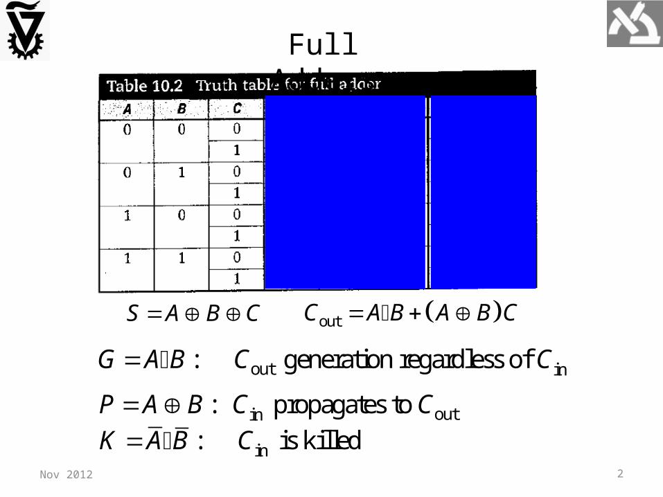
Full Adders
S A B C outC A B A B C
outin: propagates to P A B C C out in: generation regardless of G A B C C
in: is killed K A B C Nov 2012

3
out MAJ , ,C AB AC BC A B C
S A B C P C
32 tranistors
N and P networks are identical rather than complementary!
Design I: Mirror CMOS logic
Nov 2012
kill
generate
1-propagate
0-propagate
odd 1s
odd 0s

4
Design II: S is factored to reuse Cout
Uses only 28 transistors. Can be reduced to 24 transistors. S has larger delay but it is not on the critical path
outS ABC A B C C
Nov 2012
kill
generate1-propagate
0-propagateodd 1s
odd 0s

5Nov 2012
The transistors connected to Cin are closest to the output of the carry (and sum) circuits. (why?)Only the transistors of the carry are optimized for speed. (why?)
6
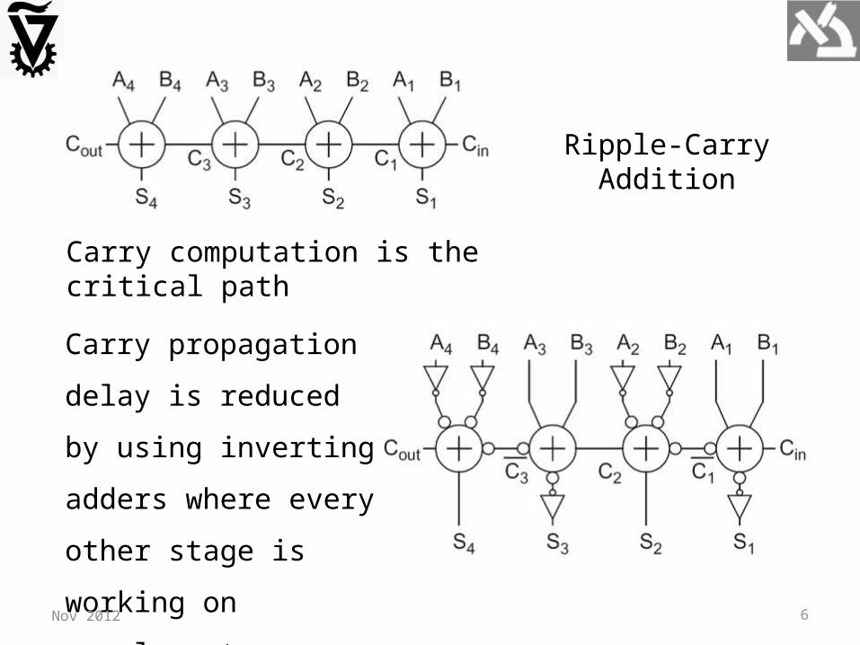
Ripple-Carry Addition
Carry computation is the critical path
Carry propagation delay is
reduced by using inverting
adders where every other
stage is working on
complementary data.
Nov 2012

7
XOR / XNOR Circuits
Straight-forward, 16 transistors
14 transistors
Complementary CMOS, 12 transistors
More efficient, less contacts, smaller layout, commonly used in STD cell Lib.
Nov 2012
8
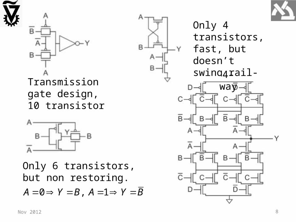
Transmission gate design, 10 transistor
Only 6 transistors, but non restoring.
0 , 1A Y B A Y B
Only 4 transistors, fast, but doesn’t swing rail-to-rail.
4-way
Nov 2012

9
S A B C P C Full-adder using XOR and MUX
24 transistors and buffered outputs. Cout and S have same delay.
Nov 2012

10
Carry-Propagate Addition
Ripple-Carry Addition
outin: propagates to P A B C C out in: generation regardless of G A B C C
Recall:
Generate and Propagate signals are a key for fast addition
Carry computation is the critical path in addition
Nov 2012
11
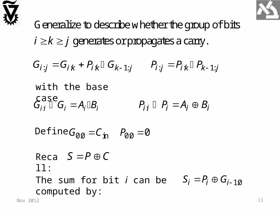
Generalize to describe whether the group of bits
generates or propagates a carry.i k j
: : : 1: i j i k i k k jG G P G : : 1: i j i k k jP P P
:i i i i iG G A B :i i i i iP P A B
with the base case
0:0 0:0in 0G C P Define
S P C Recall:
1:0i i iS P G The sum for bit i can be computed by:
Nov 2012

12
Addition is reduced into 3-step computation process
bitwise propagateand generate logic
group propagateand generate logic
sum logic
Addition acceleration is obtained by smart PG grouping Nov 2012

13Nov 2012
shared bitwise propagate-generate (PG) logic
To use fewer stages for carry propagation, higher valency comprising more complex gates is possible, e.g. valency-4:
: 1:: : 1: 1: 1: 1:i j m ji k i k k l k l l m l mG G P G P G P G
: 1:: 1: 1: i j m ji k k l l mP P P P P i k l m j
: : : 1: i j i k i k k jG G P G : : 1: i j i k k jP P P
A combined pair of smaller groups is called valency-2 group PG logic.
i k j

14
PG Carry-Ripple Addition
Nov 2012
1 1 1i i i i i i i i i i ii i iC A B A B C A B A B C G PC
15Nov 2012
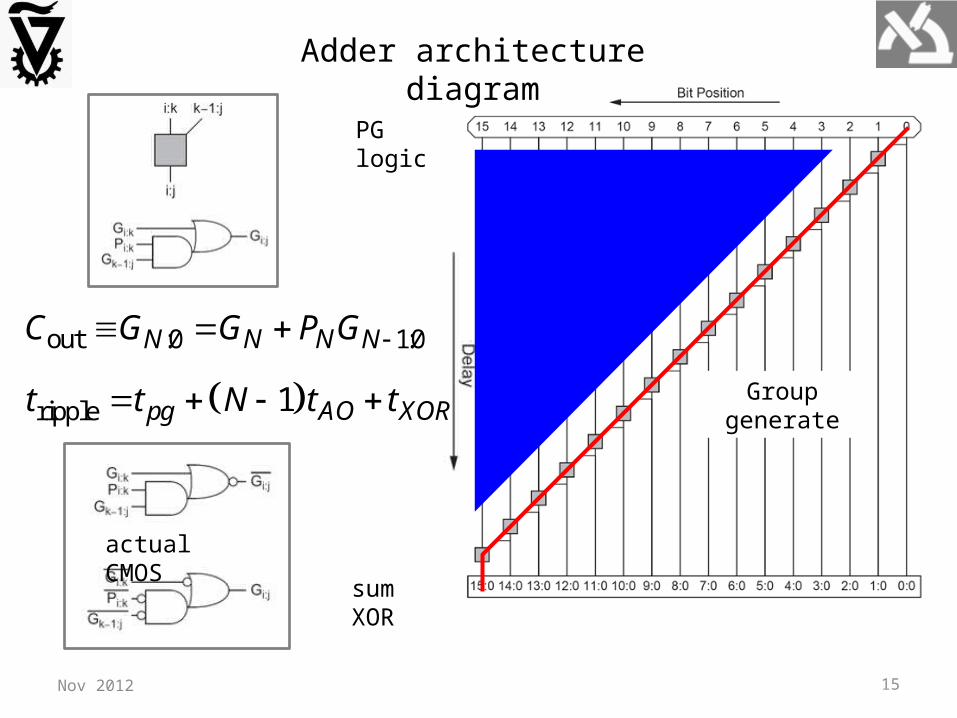
Adder architecture diagram
out :0 1:0N NN NC G G P G
PG logic
sum XOR
ripple 1pg AO XORt t N t t
actual CMOS
Group generate
16
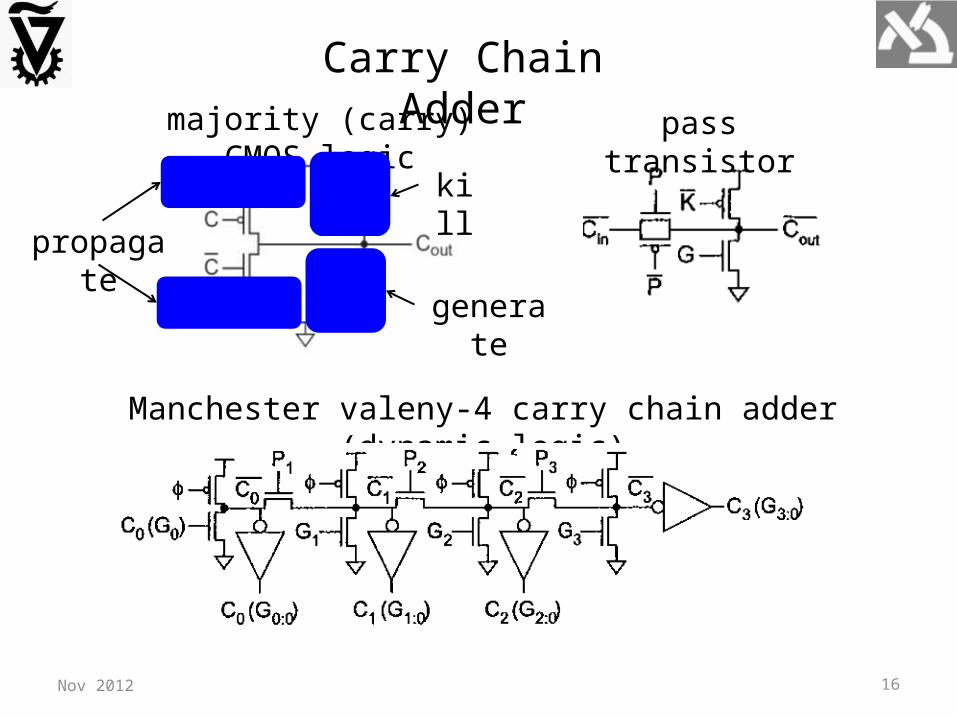
majority (carry) CMOS logic
Nov 2012
generate
propagate
kill
Carry Chain Adderpass transistor
Manchester valeny-4 carry chain adder (dynamic logic)
17Nov 2012
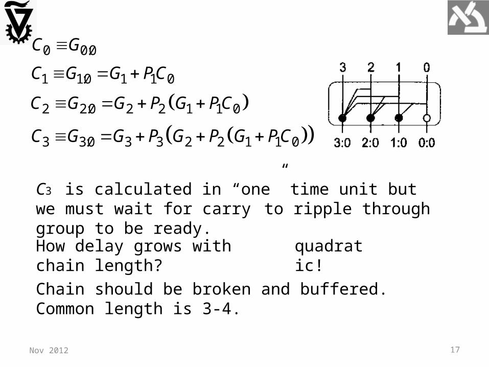
0 0:0C G
1 1:0 1 1 0C G G PC
2 2:0 2 2 1 1 0C G G P G PC
3 3:0 3 3 2 2 1 1 0C G G P G P G PC
C3 is calculated in “one” time unit but we must wait for carry
to ripple through group to be ready.
How delay grows with chain length? quadratic!
Chain should be broken and buffered. Common length is 3-4.
18Nov 2012
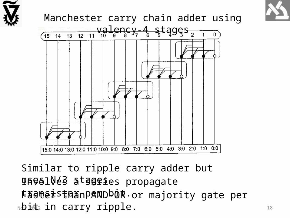
Manchester carry chain adder using valency-4 stages
Similar to ripple carry adder but uses N/3 stages.Involves a series propagate transistor per bit. Faster than AND-OR or majority gate per bit in carry ripple.

19Nov 2012
Carry Skip Adder
Assume that the propagate computed for a group i:j is 1. : 1
ji j k kk iP A B Consequently, the carry-out of group i:j is the same as the carry-in and carry computation can be skipped.
bitwise propagate and generate + group propagateskip MUXskip path

20
Carry-skip adder Manchester stage (dynamic logic)
Nov 2012
skip MUX
jkk iP
For group propagate 0 the carry generated within group is taken.
This is a considerable acceleration compared to carry-ripple, while hardware overhead is small.
Was proposed in 19th century by Charles Babbage and used by mechanical calculators.
21Nov 2012
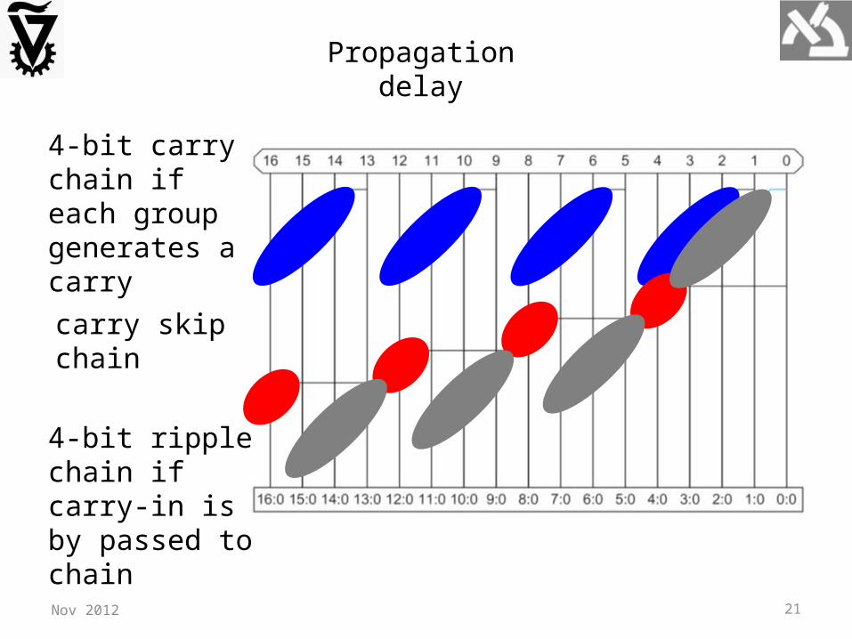
Propagation delay
4-bit carry chain if each group generates a carry
carry skip chain
4-bit ripple chain if carry-in is by passed to chain

22Nov 2012
N-bit adder with k groups of n bits each (N=kn).
First chain must compute sums and carry within n-1 delay units.
Carry propagates through k-2 stages.
Last chain must compute sums within n-1 delay units.
Delay of a chain is slower than skip propagation delay (AND, MUX).

23Nov 2012
carry-skip
first chain last chainskips
1 2 1 2 4N N
T n n nn n
carry-skip opt22
2
dT N Nn
dn n opt
carry-skip 2 2 4T N
Example: consider 32-bit addition.
optcarry-skip 2 2 32 4 12, compared to 32 units in
carry-ripple adder.
T
Question: Can we further accelerate carry propagation?
Answer: Yes we can, block size may vary across adder.

24Nov 2012
Consider t ripple-carry adder groups A0, A1, … , At-2, At-1. How
should we distribute the N bits in those blocks?
Assume a skip chain of A1, … , At-2. Since skip is far faster than
ripple carry, we wish to minimize the number b of bits in A0
and At-1.
, 1 , , 2 1 , 2 1 , , 1 , b b b t b t b b Bits are distribute as follows:
Summing over all blocks:
2 1
0
1 12
4 2 4 2t
i
t N tN b i t b b
t

25Nov 2012
carry-skip
first chain skips last chain
21 2 1 3
2
N tT b t b
t
optcarry-skip
opt2carry-skip
21 2
2 2 3
t NdT N
dt T Nt
opt
opt#blocks(var) 2
2#blocks(fixed) 2
t N
N n N
number of blocks is increased
optcarry-skipopt
carry-skip
(var) 2 3 1
2 2 4 2(fixed)
T N
NT
delay is decreased
26Nov 2012
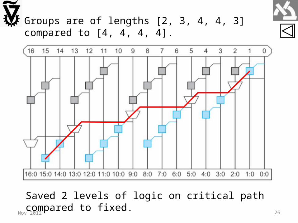
Groups are of lengths [2, 3, 4, 4, 3] compared to [4, 4, 4, 4].
Saved 2 levels of logic on critical path compared to fixed.

27Nov 2012
SubtractionHow to compute A-B?
1A B A B Recall that in 2’s complement
We’d like to combine adder and subtracter in one circuit
28
Valency-4 PG
Nov 2012
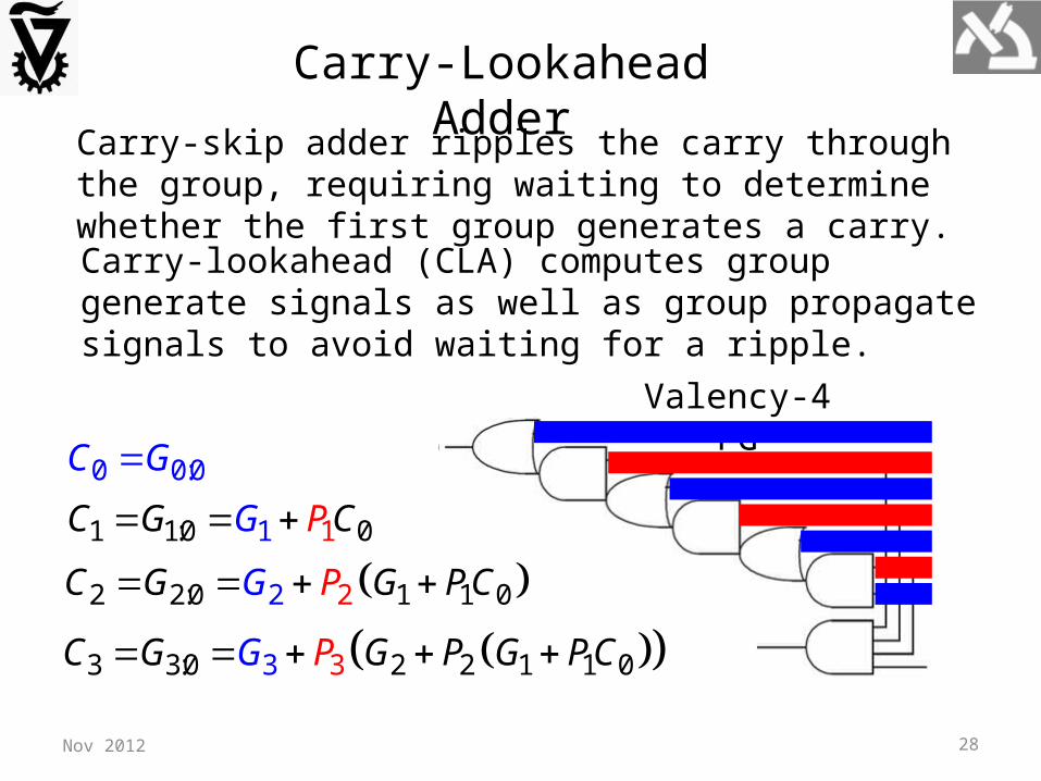
Carry-Lookahead Adder
Carry-skip adder ripples the carry through the group, requiring waiting to determine whether the first group generates a carry.
Carry-lookahead (CLA) computes group generate signals as well as group propagate signals to avoid waiting for a ripple.
0 0:0C G
1 1:0 1 1 0GC G CP
22 2:0 12 1 0C G G PCPG
33 3:0 2 2 1 13 0C G GG P P G PC
29Nov 2012
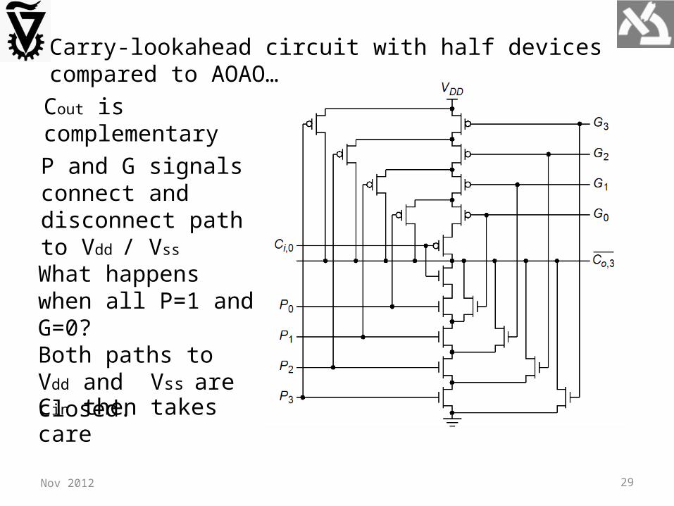
Carry-lookahead circuit with half devices compared to AOAO…
Cout is complementary
What happens when all P=1 and G=0? Both paths to Vdd and Vss are closed.
P and G signals connect and disconnect path to Vdd / Vss
Cin then takes care

30Nov 2012
group PGAND-OR
N-bit adder with k groups of n bits each (N=kn).
31Nov 2012
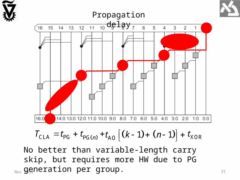
Propagation delay
CLAT PG nt AO 1t k 1n PGt XORt
No better than variable-length carry skip, but requires more HW due to PG generation per group.

32Nov 2012
Commercial MSI 4-bit CLA adder
bit PG
2-level logic CLA
sum

33Nov 2012
Carry-Select AdderThe critical paths in carry-skip and carry-lookahead involves carry calculation into each n-bit group and then using it for the sums within the group.
It is possible to pre compute the outputs for both 0/1 carry inputs and then select accordingly.
If C4=0, top adder applies for C8.
If C4=1 bottom adder applies for C8. Notice that cout(cin=1) >= cout(cin=0).

34Nov 2012
1st group computes carry out
Compute for both carries
Select accordingly
selectT PGt
Simultaneous PG for all bits
AOt n
n-bits of first group adder
2k MUXtPropagation delay

35Nov 2012
Carry-select adder is fast but the amount of circuits is about
twice compared to others. This is both power and area penalty.
The PG and XOR circuits are similar
in 0 and 1 adders, independent ,
hence MUX can be used to select
the proper input of XOR.
This is called carry-increment adder.
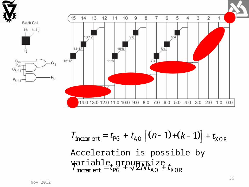
Carry-Increment Adder
36Nov 2012
incrementT PGt XORt AO 1t n 1k Acceleration is possible by variable group size
PG AO XORincrement 2T t Nt t
37Nov 2012
Tree Adders
In wide adders the delay of the carry passing through stages becomes dominant.
The delay can be reduced by looking ahead across lookahead blocks.
The square root delay can be improved to logarithmic delay by constructing multilevel lookahead structures.
There are many ways to build lookahead trees, offering tradeoffs between number of circuits, fan-out and amount of interconnects. Those are translated into area and power.
Such adders are known as lookahead adders, logarithmic adders or parallel-prefix adders.
38Nov 2012
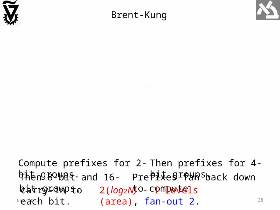
Brent-Kung tree
Compute prefixes for 2-bit groups. Then prefixes for 4-bit groups.Then 8-bit and 16-bit groups. Prefixes fan back down to computecarry-in to each bit. 2(log2N) - 1 levels (area), fan-out 2.

39Nov 2012
Sklansky tree
Intermediate prefixes can be computed along with those of large groups.
Delay reduced to log2N. Fan out is doubled at each row. Transistor sizing and buffering is required (area, power).

40Nov 2012
Kogge-Stone tree
Achieves log2N stages. Fan out is 2.Wire length grows is quadratic with N. It significantly increases area, buffers, power.

41Nov 2012
Han-Carlson tree
Use Kogge-Stone on odd bits. Use one more stage to ripple into even bits.

42Nov 2012
Comparison of Adder ArchitecturesArchitecture Logic Levels Max
Fan-out# Wiring Tracks
# Cells
Ripple-Carry 1 1
Carry-Skip (n=4) 2 1
Carry-Increment (n=4) 4 1
Carry-Increment (var.) 1
Brent-Kung 2 1
Sklansky 1
Kogge-Stone 2
Han-Carlson 2
2N
22log 1N
2log N
2log N
2log 1N
2N
2 1N
2N
4N
4 5N 4 2N
1N 1N
1.25N
2N
2N
20.5 logN N
2logN N
20.5 logN N
2N
PG and XOR logic is not counted.
Ripple-carry should be used when they meet timing constraints (small area and power).For 64 bits and up tree adders are distinctly faster.

43Nov 2012
Logic synthesizers automatically map the “+” operator into appropriate adder to meet timing constraints while minimizing area and power (aka design ware).
44
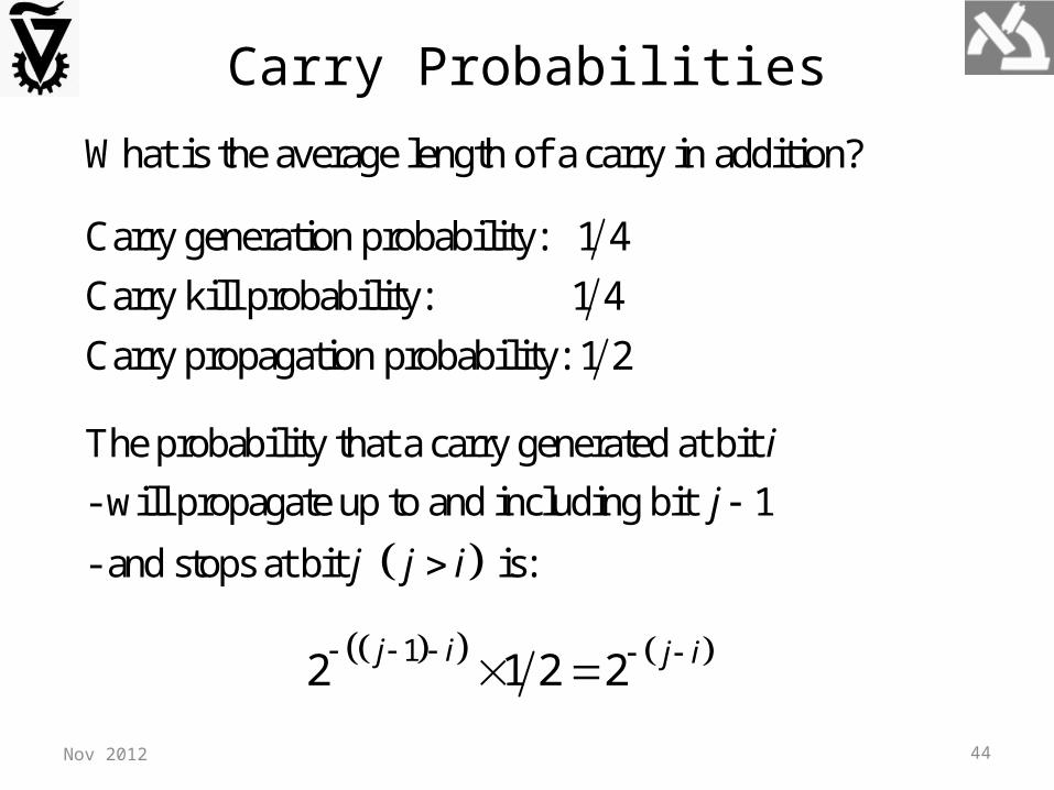
Carry Probabilities
Carry generation probability: 1 4
Carry kill probability: 1 4
Carry propagation probability: 1 2
The probability that a carry generated at bit
- will propagate up to and including bit 1
- and stops at bit is:
i
j
j j i
12 1 2 2
j i j i
What is the average length of a carry in addition?
Nov 2012

45
For a -bit adder, the expected length of a carry generated
at bit is:
k
i
1by induction 2 2 2 2
p l pll p
stops does not stop
1 11
1 11
1 1 1
2 2
2 2
2 1 2 2 2 2
k j i k ij i
k i k ill
k i k i k i
j i k i
l k i
k i k i
Consequently, for long adders ( ) the avarage length
of carry propagation is nearly 2.
i k
Nov 2012
46
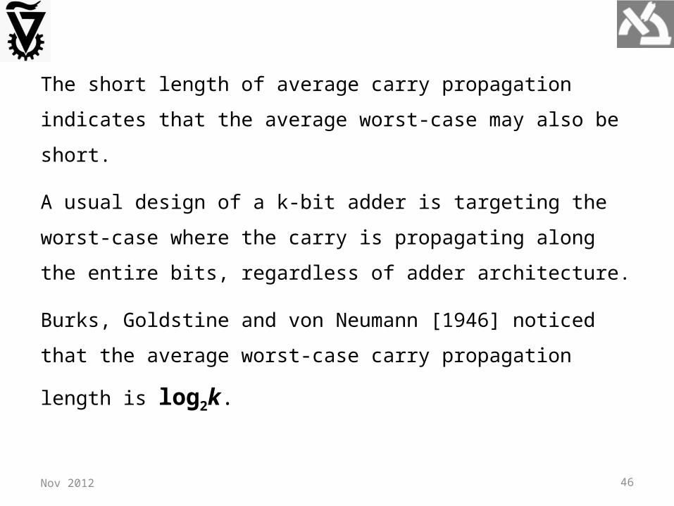
The short length of average carry propagation indicates
that the average worst-case may also be short.
A usual design of a k-bit adder is targeting the worst-case
where the carry is propagating along the entire bits,
regardless of adder architecture.
Burks, Goldstine and von Neumann [1946] noticed that
the average worst-case carry propagation length is log2k.
Nov 2012
47
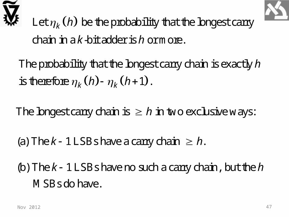
Let be the probability that the longest carry
chain in a -bit adder is or more.k h
k h
The probability that the longest carry chain is exactly
is therefore 1 .k k
h
h h
(b) The 1 LSBs have no such a carry chain, but the
MSBs do have.
k h
The longest carry chain is in two exclusive ways:h
(a) The 1 LSBs have a carry chain .k h
Nov 2012

48
1 11 1 1
case (b)
case (a) not case (a) carry generatedand propagatedalong 1 bits
11 2 2 .
4h h
k k k k
h
h h h h
Thus, we have
11Therefore, 2 . Assuming 0 for ,h
k k ih h h i h
1 11 1 2 2 .
kh h
k i ii h
h h h k h k
1
1
The expected length of the longest carry chain
1 1 2 2 2 3
0 .
k
k k k k k kh
k
k kh
h h h
k k h
Nov 2012
49
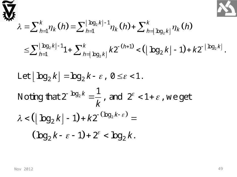
2
2
2 2
2
log 1
1 1 log
log 1 log121 log
1 2 log 1 2 .
k k kk k kh h h k
k k khh h k
h h h
k k k
2 2Let log log , 0 1.k k
2
2
log
log2
2 2
1Noting that 2 , and 2 1 , we get
log 1 2
log 1 2 log .
k
k
k
k k
k k
Nov 2012

50
Carry-Completion DetectionWorst-case carry propagation of length k almost never materializes.
A carry-completion detection adder performs addition in average O(log2k) time.
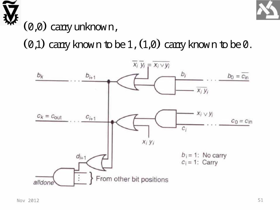
A carry 0 is also explicitly represented and allowed to propagate between stages. The carry into stage i is represented by the two-rail code:
0,0 Carry not yet known
, 0,1 Carry known to be 1
1,0 Carry known to be 0i ib c
Nov 2012
51Nov 2012
0,0 carry unknown,
0,1 carry known to be 1, 1,0 carry known to be 0.
52
Two 1s generate a carry of 1 propagating towards MSB.
Two 0s generate a carry of 0 propagating towards MSB.
Initially, all carries are (0,0), namely, unknown.
Nov 2012
in inThe carry ( , ) is injected into the LSB.c c
When every carry assumes one of the values (0,1) or (1,0) carry propagation is complete.
The local "done" signals = are ANDed to form
the global signal, indicating carry propagation
completion.
i i id b c
alldone

53
Excluding initialization and carry-completion detection times, the latency of k-bit carry-completion adder ranges from 1 to 2k+1 gate delays, with 2log2k+1 average gate delays.
Nov 2012
Behrooz Parhami, Computer Arithmetic, Oxford, 2010, page 100:
"Because the latency of the carry-completion adder is data-dependent, the design of Fig. 5.9 is suitable for use in asynchronous systems. Most modern computers, however, use synchronous logic and thus cannot take advantage of the high average speed of a carry-completion adder."
Related Documents