Adding Feedforward Blade Pitch Control to Standard Feedback Controllers for Load Mitigation in Wind Turbines ✩ Fiona Dunne a,1 , Lucy Y. Pao a,2 , Alan D. Wright b,3 , Bonnie Jonkman b,4 , Neil Kelley b,5 a Dept. of Electrical, Computer, and Energy Engineering, University of Colorado, Boulder, CO b National Wind Technology Center, National Renewable Energy Laboratory, Golden, CO Abstract Combined feedback/feedforward blade pitch control is compared to indus- try standard feedback control when simulated in realistic turbulent winds. The feedforward controllers are designed to reduce fatigue loads, increasing turbine lifetime and therefore reducing the cost of energy. Two feedforward designs are studied: collective-pitch model-inverse feedforward using a non- causal series expansion and individual-pitch gain-scheduled shaped compen- sator. The input to the feedforward controller is a measurement of incoming wind speed, which could potentially be provided by LIDAR. Three of the designs reduce structural loading compared to standard feedback control, without reducing power production. ✩ Employees of the Midwest Research Institute under Contract No. DE-AC36- 99GO10337 with the U.S. Dept. of Energy have authored this work. The United States Government retains, and the publisher, by accepting the article for publication, acknowl- edges that the United States Government retains a non-exclusive, paid-up, irrevocable, worldwide license to publish or reproduce the published form of this work, or allow others to do so, for the United States Government purposes. Email addresses: [email protected] (303)492-4083 (Fiona Dunne), [email protected] (Lucy Y. Pao) 1 Doctoral Candidate, Corresponding Author 2 Richard and Joy Dorf Professor 3 Senior Engineer 4 Senior Scientist 5 Principal Scientist Preprint submitted to Mechatronics November 15, 2010

Welcome message from author
This document is posted to help you gain knowledge. Please leave a comment to let me know what you think about it! Share it to your friends and learn new things together.
Transcript
Adding Feedforward Blade Pitch Control
to Standard Feedback Controllers
for Load Mitigation in Wind TurbinesI
Fiona Dunnea,1, Lucy Y. Paoa,2, Alan D. Wrightb,3, Bonnie Jonkmanb,4,Neil Kelleyb,5
aDept. of Electrical, Computer, and Energy Engineering, University of Colorado,Boulder, CO
bNational Wind Technology Center, National Renewable Energy Laboratory, Golden, CO
Abstract
Combined feedback/feedforward blade pitch control is compared to indus-try standard feedback control when simulated in realistic turbulent winds.The feedforward controllers are designed to reduce fatigue loads, increasingturbine lifetime and therefore reducing the cost of energy. Two feedforwarddesigns are studied: collective-pitch model-inverse feedforward using a non-causal series expansion and individual-pitch gain-scheduled shaped compen-sator. The input to the feedforward controller is a measurement of incomingwind speed, which could potentially be provided by LIDAR. Three of thedesigns reduce structural loading compared to standard feedback control,without reducing power production.
IEmployees of the Midwest Research Institute under Contract No. DE-AC36-99GO10337 with the U.S. Dept. of Energy have authored this work. The United StatesGovernment retains, and the publisher, by accepting the article for publication, acknowl-edges that the United States Government retains a non-exclusive, paid-up, irrevocable,worldwide license to publish or reproduce the published form of this work, or allow othersto do so, for the United States Government purposes.
Email addresses: [email protected] (303)492-4083 (Fiona Dunne),[email protected] (Lucy Y. Pao)
1Doctoral Candidate, Corresponding Author2Richard and Joy Dorf Professor3Senior Engineer4Senior Scientist5Principal Scientist
Preprint submitted to Mechatronics November 15, 2010

Keywords: wind turbine, pitch control, feedforward, feedback, LIDAR,model-inverse
Nomenclature
P Linearized model of wind turbineo Output errorb Collective blade pitch feedforward commandbcmd Collective blade pitch errorw Deviation from nominal wind speedPobcmd
Open-loop turbine transfer function from collective pitch errorto output error
Pow Open-loop turbine transfer function from wind speed errorto output error
Tob Closed-loop transfer function from collective pitch feedforwardcommand to output error
Tow Closed-loop transfer function from wind speed error to output errorF Feedforward controllerCP Collective PitchIP Individual PitchDOF Degree of FreedomDEL Damage Equivalent LoadF-A Fore-aftIMU Inertial measurement unitMBC Multi-blade coordinate transformationNCSE Non-causal series expansionNMP Non-minimum phase
1. Introduction
Current commercial wind turbine blade pitch control algorithms are typ-ically feedback only, as shown in Figure 1. Blade pitch is often controlledby a simple proportional-integral (PI) based collective blade pitch controller,which receives its input signal from the error in generator speed. Recentwork [1, 2, 3, 4] has verified that more advanced feedback controllers canreduce structural fatigue loads. These advanced controllers typically employ
2

individual pitch control and may be based on signals from strain gauges andposition encoders in addition to generator speed.
LIDAR (Light Detection and Ranging) can be used to remotely measurewind speed. Recent improvements in LIDAR size, cost, and reliability havemade it realistic to obtain accurate wind speed measurements upstream ofthe turbine. When wind speed measurements are available, we can makeuse of this additional information through disturbance feedforward control.This feedforward control can be combined with either standard or advancedfeedback control, as shown in Figure 2. The use of these wind speed mea-surements to reduce turbine fatigue loads is an area that is being activelyresearched. Harris et al. [5] have studied disturbance accommodating controlwith inputs from a Lidar simulator. Laks et al. [6, 7, 8] have studied com-bined feedforward/feedback MIMO control with preview wind speed inputs.Schlipf and Kuhn [9] have studied feedforward control added to standardfeedback control, where the feedforward controller is a gain-scheduled staticgain with a low pass filter.
Figure 1: Feedback Only Control
Figure 2: Combined Feedback/Feedforward Control
In this study, a feedforward controller is also added on to a standardfeedback controller, but the two types of feedforward controllers studied aredifferent than the design in [9]. The results are compared to the standardfeedback controller alone. This study also includes individual pitch variations
3

of combined feedforward and feedback control. Simulation results in realisticturbulent wind fields will show that when the feedforward control is addedon, it can reduce fatigue loads without reducing power capture.
This paper is organized as follows. In Section II, we describe the windturbine model, baseline controllers, and wind fields used in simulations. Feed-forward blade pitch control designs are described in Section III. Section IVpresents simulation results. Finally, Section V contains a summary of con-clusions and future work.
2. Simulated Turbine and Turbulent Inflow
2.1. 5 MW Turbine Model and Baseline Control
All simulations are performed using a full non-linear turbine model pro-vided by the FAST [10] software code developed at the US National Re-newable Energy Laboratory (NREL). FAST is an aeroelastic simulator thatmodels a turbine as a combination of rigid bodies and bodies with flexiblemodes, and can predict extreme and fatigue turbine loads. The particularmodel used in FAST is the NREL 5 MW reference turbine [11], simulated inonshore conditions, with the following specifications:
• 3-bladed, upwind, variable speed turbine
• 90 meter hub height
• 126 meter rotor diameter
• Individual blade pitching capability
• 11.4 m/s rated wind speed
• 12.1 rpm rated rotor speed, 1173.7 rpm rated generator speed
• gear box ratio of 97
All available degrees of freedom are turned on in simulations:
• First flapwise blade mode
• Second flapwise blade mode
• First edgewise blade mode
4
• Drivetrain rotational-flexibility
• Generator
• Yaw
• First fore-aft tower bending-mode
• Second fore-aft tower bending-mode
• First side-to-side tower bending-mode
• Second side-to-side tower bending-mode
The control inputs to the FAST wind turbine model are pitch commandsfor each of the three blades, along with yaw and generator torque. Theyaw control is set to a constant 0◦, and the average wind direction does notchange. In above rated wind speeds, generator torque control is set to be in-versely proportional to generator speed in order to maintain constant power.FAST turbine model outputs to be controlled include generator speed, bladebending moments, tower bending moments, and accelerations and velocitiesfrom nacelle inertial measurement units (IMUs).
The baseline collective pitch controller is a PI generator speed controller,gain-scheduled on pitch angle [11].
An individual pitch feedback-only controller was also designed [1] for useas another baseline controller for comparison with the individual pitch feed-forward controllers. In addition to generator speed, its inputs are the threeout-of-plane blade root bending moments, and the rotor azimuth, which isused for the multi-blade coordinate (MBC) transformation (called d-q axistransformation in [1]). The horizontal and vertical components are controlledwith PI controllers, and the collective component is controlled with the samePI feedback control as the baseline collective pitch controller. The horizontaland vertical component PI controllers were tuned manually in Matlab’s [12]SISO Design Tool using a linear model of the MBC-transformed turbine. Thebaseline IP controller, in above rated wind fields, averages an almost 30% re-duction in blade root flapwise DEL compared to the baseline CP controller,accomplished with an approximately 2 deg/s higher peak pitch rate. Otherloads are relatively unchanged.
5
2.2. Stochastic Turbulent Wind Field Simulator
The NREL TurbSim [13] stochastic full-field inflow simulator was used toprovide realistic wind fields for the turbine simulations. These simulationsare based on extensive observations taken in the high-plains environment ofSoutheast Colorado that is now a large operating wind farm. The GreatPlains (GP-LLJ) spectral model available in TurbSim was used to simulatewind conditions present at this site.
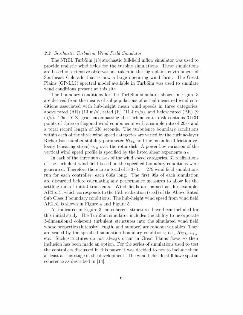
The boundary conditions for the TurbSim simulator shown in Figure 3are derived from the means of subpopulations of actual measured wind con-ditions associated with hub-height mean wind speeds in three categories:above rated (AR) (13 m/s), rated (R) (11.4 m/s), and below rated (BR) (9m/s). The (Y-Z) grid encompassing the turbine rotor disk contains 31x31points of three orthogonal wind components with a sample rate of 20/s anda total record length of 630 seconds. The turbulence boundary conditionswithin each of the three wind speed categories are varied by the turbine-layerRichardson number stability parameter RiTL and the mean local friction ve-locity (shearing stress) u∗D over the rotor disk. A power law variation of thevertical wind speed profile is specified by the listed shear exponents αD.
In each of the three sub cases of the wind speed categories, 31 realizationsof the turbulent wind field based on the specified boundary conditions weregenerated. Therefore there are a total of 3 ·3 ·31 = 279 wind field simulationsrun for each controller, each 630s long. The first 99s of each simulationare discarded before calculating any performance measures to allow for thesettling out of initial transients. Wind fields are named as, for example,AR3 s15, which corresponds to the 15th realization (seed) of the Above RatedSub Class 3 boundary conditions. The hub-height wind speed from wind fieldAR1 s1 is shown in Figure 4 and Figure 5.
As indicated in Figure 3, no coherent structures have been included forthis initial study. The TurbSim simulator includes the ability to incorporate3-dimensional coherent turbulent structures into the simulated wind fieldwhose properties (intensity, length, and number) are random variables. Theyare scaled by the specified simulation boundary conditions; i.e., RiTL, u∗D ,etc. Such structures do not always occur in Great Plains flows so theirinclusion has been made an option. For the series of simulations used to testthe controllers discussed in this paper it was decided to not to include themat least at this stage in the development. The wind fields do still have spatialcoherence as described in [14].
6
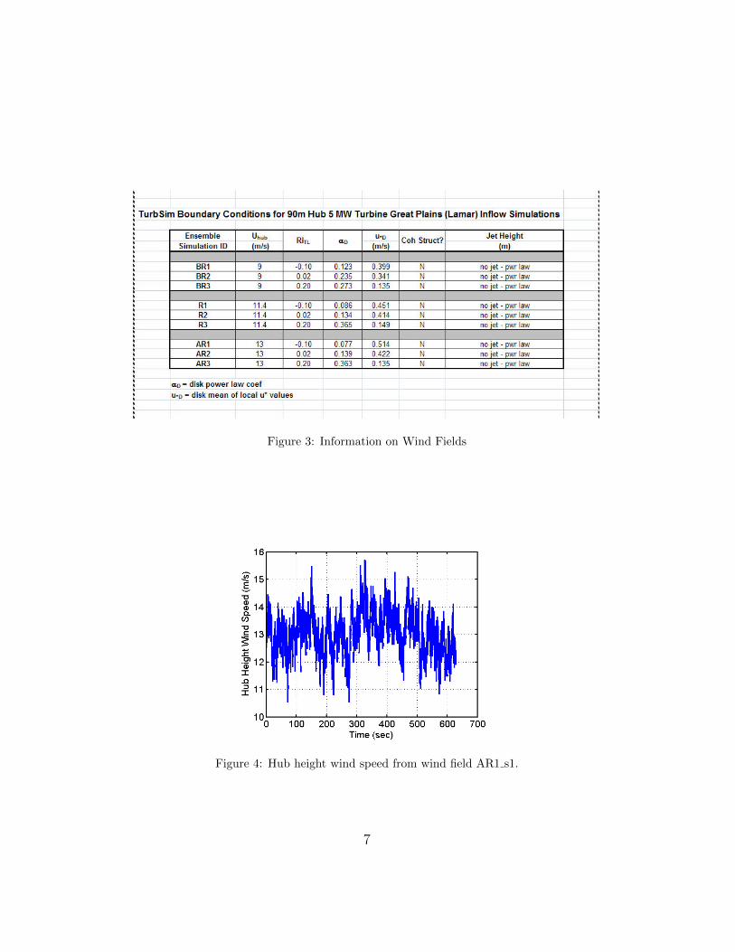
Figure 3: Information on Wind Fields
Figure 4: Hub height wind speed from wind field AR1 s1.
7
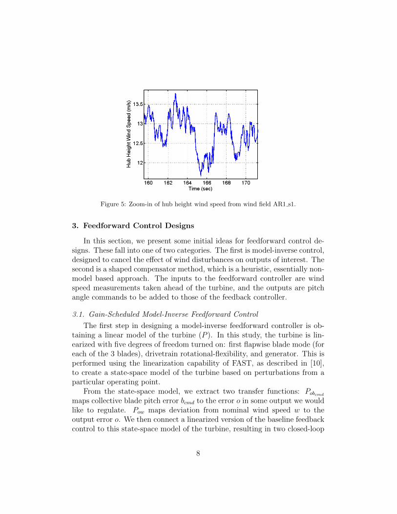
Figure 5: Zoom-in of hub height wind speed from wind field AR1 s1.
3. Feedforward Control Designs
In this section, we present some initial ideas for feedforward control de-signs. These fall into one of two categories. The first is model-inverse control,designed to cancel the effect of wind disturbances on outputs of interest. Thesecond is a shaped compensator method, which is a heuristic, essentially non-model based approach. The inputs to the feedforward controller are windspeed measurements taken ahead of the turbine, and the outputs are pitchangle commands to be added to those of the feedback controller.
3.1. Gain-Scheduled Model-Inverse Feedforward Control
The first step in designing a model-inverse feedforward controller is ob-taining a linear model of the turbine (P ). In this study, the turbine is lin-earized with five degrees of freedom turned on: first flapwise blade mode (foreach of the 3 blades), drivetrain rotational-flexibility, and generator. This isperformed using the linearization capability of FAST, as described in [10],to create a state-space model of the turbine based on perturbations from aparticular operating point.
From the state-space model, we extract two transfer functions: Pobcmd
maps collective blade pitch error bcmd to the error o in some output we wouldlike to regulate. Pow maps deviation from nominal wind speed w to theoutput error o. We then connect a linearized version of the baseline feedbackcontrol to this state-space model of the turbine, resulting in two closed-loop
8

transfer functions: Tob maps collective blade pitch feedforward input b to theerror o in some output we would like to regulate. Tow maps deviation fromnominal wind speed w to the output error o.
A feedforward controller is shown as F in Figure 6. A linear model-inversefeedforward approach uses F to cancel the effect of w on o. Therefore, ascan be seen in Figure 6,
Tob · F · w = −Tow · wF = −T−1
ob Tow
(odesired = 0)
Figure 6: Combined Feedback/Feedforward Control
In the special case when o = ofb (e.g. when the output of interest isgenerator speed error, the same output used in the collective-pitch feedbackloop), it turns out that the closed-loop transfer functions Tob and Tow eachdiffer from their corresponding open loop transfer functions in the same way,so that F = −T−1
ob Tow = −P−1obcmd
Pow, and it doesn’t matter whether you usethe open-loop or closed-loop transfer functions. However, when o 6= ofb, it isimportant to use the closed-loop transfer functions when finding F .
Ideally, the feedforward controller would be set exactly equal to F asabove. However, in this case the resulting F is unstable because Tob containsnon-minimum phase (NMP) zeros. Therefore a stable model-inverse approxi-mation is used instead. It is unknown exactly where the non-minimum phasezeros come from. Some are present in the continuous-time transfer function,and others appear after conversion to discrete time [15]. In continuous time,when the output o is generator speed, for example, and the only DOF isthe generator DOF, there are no NMP zeros in either Pobcmd
or Pow. Whenthe drivetrain rotational-flexibility DOF is turned on as well, both transferfunctions gain a NMP zero at around 107 rad/s. When only generator and
9

first blade flap DOFs are turned on, only Pobcmdhas a NMP zero at around 4
rad/s. When generator, drivetrain rotational-flexibility, and first blade flapDOFs are all turned on, Pobcmd
still has a NMP zero at around 4 rad/s, andthere is a minimum-phase zero near −107 rad/s instead of a NMP zero near107 rad/s in both transfer functions. So it is likely that turning on drivetrainrotational-flexibility actually adds a zero at infinity to both transfer func-tions, but for numerical reasons it sometimes appears as a large NMP zero.Turning on the first blade flap DOFs however consistently adds a NMP zeronear 4 rad/s to Pobcmd
. While non-colocation of actuators and sensors is acommon reason for the existence of NMP zeros, it is often difficult to fullyexplain their existence [16].
In previous work [17], three different model-inverse techniques [18] weretried: the nonminimum-phase zeros ignore (NPZ-Ignore), the zero-phase-error tracking controller (ZPETC), and the zero-magnitude-error trackingcontroller (ZMETC). These worked well when controlling a linear plant model,but performed worse than the baseline controller alone when simulated inFAST. This paper discusses a different model-inverse approximation method:non-causal series expansion (NCSE) [19]. NPZ-Ignore is actually a 0-orderNCSE, but here we will discuss higher orders of NCSE. This type of inver-sion requires the most preview time and should theoretically provide a betterapproximate inverse than the other three methods.
The NCSE method results in a stable approximate model-inverse by usinga Taylor series approximation. For example, if the desired F contains anunstable pole a, where |a| > 1, then we replace
1
z − awith
−(
1
a
)−(
1
a
)2
z −(
1
a
)3
z2 . . .
which is stable, but non-causal. For each term included in the approximation,an additional sample of preview is required.
Other improvements were also made in addition to changing the approx-imate inversion method. The three previous model-inverse controllers weredesigned to regulate the generator speed output, with the hope that theywould also reduce structural loads. This NCSE control is instead directlydesigned to regulate the blade root bending moment output. The previ-ous controllers were based on a model linearized about an operating point
10

of 18 m/s wind speed and were gain scheduled, while this NCSE control islinearized at 13 m/s to better match simulation conditions and is not gainscheduled. Lowpass filtering was also treated differently: The original designhad one lowpass filter on the linear feedforward controller, and a differentlowpass filter on its gain-scheduling multiplier. The new design has no gain-scheduling multiplier, but instead has two parts described below, each with adifferent lowpass filter. Finally, the wind speed measurement fed to the feed-forward control in previous simulations was an average of five points takenat the hub and outer edges of the rotor plane. Now it is an average of threepoints, one at 75% span of each blade, since, accounting for tip losses, theblades are most sensitive to wind speed around this span location [9].
The NCSE control was first tested on the linear model for varying val-ues of three options: approximation order, sample rate used in conversion todiscrete time, and number of degrees of freedom turned on in linearization.Different designs were compared using the H2 norm from wind speed errorto root bending moment error, weighted based on the frequency spectrum ofeffective collective wind speed. This testing resulted in the following choice:approximation order=3, 80Hz sample rate, and 5 degrees of freedom in lin-earization. Higher approximation order was expected to reduce the H2 norm.The H2 norm did initially decrease as order increased from zero to three, butthen unexplained spikes and an overall increase in H2 norm occurred uponfurther increase of approximation order. Because of this small choice of ap-proximation order, only 3 samples of preview (=0.0375 sec of preview) isrequired in the wind speed measurement.
This NCSE feedforward control does not need to operate at very low fre-quencies, because we are really interested in minimizing fluctuations in rootmoment, but do not care about the steady state value. On the other hand,steady state rotor speed is very important. Therefore the overall feedforwardcontrol is the sum of a highpass filtered NCSE control and a lowpass filteredrotor speed control, as shown in Figure 7. Both filters have a 3dB pointat 10−2 Hz, since wind begins to affect rotor speed relatively less than rootbending moment above this frequency. The rotor speed control is a simplelookup table, with values based on testing of the non-linear turbine modelat various points over a range of wind speeds from 11.4 to 25 m/s to find therequired steady-state blade pitch at each point such that rated rotor speedis maintained. The feedback controller is still working to control rotor speedas well.
11

Figure 7: Feedforward control combining rotor speed regulation at low frequencies andNCSE root bending moment reduction at higher frequencies. Linearization operatingpoints were 13 m/s wind speed and 6.537 degrees blade pitch.
3.2. Gain-Scheduled Shaped Compensator Feedforward Control
Rather than using an instantaneous wind speed measurement at theblades, or a few hundredths of a second ahead of the blades, the shapedcompensator uses an advance wind measurement up to five seconds aheadof the blades. This gives the blades more time to react to changes in windspeed, keeping pitch rates to more reasonable levels.
Figure 8: Desired Step Response of Shaped Compensator (rad/(m/s))
First, the desired step response shown in Figure 8 is created. The stepchange in wind speed hits the blades at the 0s mark on the plot, where theblade pitch is rising the fastest. The step response completely determines
12
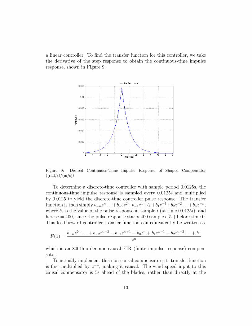
a linear controller. To find the transfer function for this controller, we takethe derivative of the step response to obtain the continuous-time impulseresponse, shown in Figure 9.
Figure 9: Desired Continuous-Time Impulse Response of Shaped Compensator((rad/s)/(m/s))
To determine a discrete-time controller with sample period 0.0125s, thecontinuous-time impulse response is sampled every 0.0125s and multipliedby 0.0125 to yield the discrete-time controller pulse response. The transferfunction is then simply b−nz
n . . .+b−2z2+b−1z
1+b0+b1z−1+b2z
−2 . . .+bnz−n,
where bi is the value of the pulse response at sample i (at time 0.0125i), andhere n = 400, since the pulse response starts 400 samples (5s) before time 0.This feedforward controller transfer function can equivalently be written as
F (z) =b−nz
2n . . .+ b−2zn+2 + b−1z
n+1 + b0zn + b1z
n−1 + b2zn−2 . . .+ bn
zn
which is an 800th-order non-causal FIR (finite impulse response) compen-sator.
To actually implement this non-causal compensator, its transfer functionis first multiplied by z−n, making it causal. The wind speed input to thiscausal compensator is 5s ahead of the blades, rather than directly at the
13

blades. This is effectively a multiplication of the wind speed input by zn,which cancels the z−n.
This compensator is then gain scheduled so that at each wind speed, itoutputs the correct steady state blade pitch to maintain rated rotor speed.
This controller was originally collective pitch. An individual pitch versionwas then designed by using three copies of the collective pitch controller,one for each blade. There are then three separate wind speed measurementinputs, 5s ahead of each blade, at 75% span.
The shaped compensator idea can also be evaluated at different windpreview lengths. In addition to the 5s preview version, we consider 10/3spreview and 5/3s preview versions of the individual pitch shaped compen-sator. These were designed by shrinking the step response to 2/3 and 1/3 ofits original length.
3.3. Phasing Out Individual Pitch Controllers
As the wind speed drops below rated, the individual pitch controllersare phased out of operation using the phase out block shown in Figure 10.The lower blade pitch limit for this turbine model is 0◦. Without a phaseout block, as the wind speed drops below rated, the controller causes thepitch of each blade to saturate at 0◦. This causes a problem for individualpitch control because each pitch command is approximately sinusoidal at therotational frequency of the turbine, and when the part of the sinusoid below0◦ is cut off, the average pitch command is suddenly higher than desired,causing reduced rotor speeds and reduced power capture.
At near rated wind speeds, where part of the sinusoids are below 0◦, thephase out block works to keep the average pitch at the correct value, whilereducing the magnitude of each sinusoid until it just reaches but does notgo below 0◦. This is done in the individual pitch feedforward controllers asfollows:
The phase out block has a 3-element vector input βin and 3-element vec-tor output βout, with one element for each blade pitch command. First,an instantaneous average of the three pitch commands is taken. avg =βin(1) + βin(2) + βin(3)
3. The difference between that average and the pitch
command farthest from that average at any given time is then taken. dif =max(|βin(1)−avg|, |βin(2)−avg|, |βin(3)−avg|). Now dif gives us an approx-imate value of the magnitude of the three βin sinusoids, but as a functionof time, it contains an undesirable ripple. Therefore it is fed into a low
14

pass filter, and the output of the low pass filter is increased by about 5%.This finally gives an estimate of the current amplitude (amp) of the threecommanded signals βin. The commanded signals are then passed throughwith the same average value, but with the amplitude scaled down so thatit just reaches the 0◦ limit. βout = avg + (βin − avg) ∗ (avg/amp). Inputsand outputs to this process are shown in Figure 11. A different method wasused in the baseline individual pitch controller, taking advantage of the MBCtransformation.
Figure 10: Phase out block for individual pitch control shown with 3-element vector inputβin and output βout. F: feedforward control C: feedback control P: plant (wind turbine)
Figure 11: Individual Pitch Control Phase Out: The top plot is βin, and the bottom plotis βout. The signals are blade pitch commands in radians over time (s).
15
4. Simulation Results
When simulated on below rated wind fields, all controllers behaved ex-actly the same: the commanded blade pitch was a constant zero degrees.
The shaped individual pitch controllers were then simulated in all aboverated and rated wind fields, and compared to the individual pitch feedback-only baseline control. A comparison of structural loading measures, averagedover all above rated wind fields, is shown in Figure 12. The same plot forrated wind fields is shown in Figure 13. These measures include RMS nacellevelocities and damage equivalent loads (DELs) of blade and tower bendingmoments. DELs are calculated based on a rainflow counting algorithm usingcode from NREL, with Wohler curve exponent (slope of log(S) vs log(N)) of10, typical for composite material. It should be noted that the side-to-sidetower top RMS velocity measure had initial transients that took much longerto settle than the others, sometimes over 100s. Since only the first 99s ofeach run were discarded to allow for settling, this particular measure maynot have actually increased as much as these plots show.
Above rated wind fields have high enough wind speeds that the bladepitch does not saturate at 0◦, the pitch angle that captures peak power forthis turbine. Rated wind fields, however, introduce the additional designchallenge of handling blade pitch saturation. Challenges include integratorwindup and the individual-pitch phase out problem described in Section 3.3.In addition, in rated wind fields, the feedforward controller can only providea benefit during times when the pitch is not saturated. Therefore above ratedresults are generally better than rated results.
Three of the designs are an improvement over IP baseline: IP Shaped 5sFdfwd w/ CP Fdbk, IP Shaped 10/3s Fdfwd w/ CP Fdbk, and IP Shaped5s Fdfwd w/ IP Fdbk. These three designs each incorporate a preview mea-surement of the incoming wind speed at three points ahead of the turbine.These three designs also do not reduce power production, and even allowtighter regulation of power production and rotor speed. These feedforwardcontrollers also generally increase pitch rates but still operate within a limitof 8◦/s.
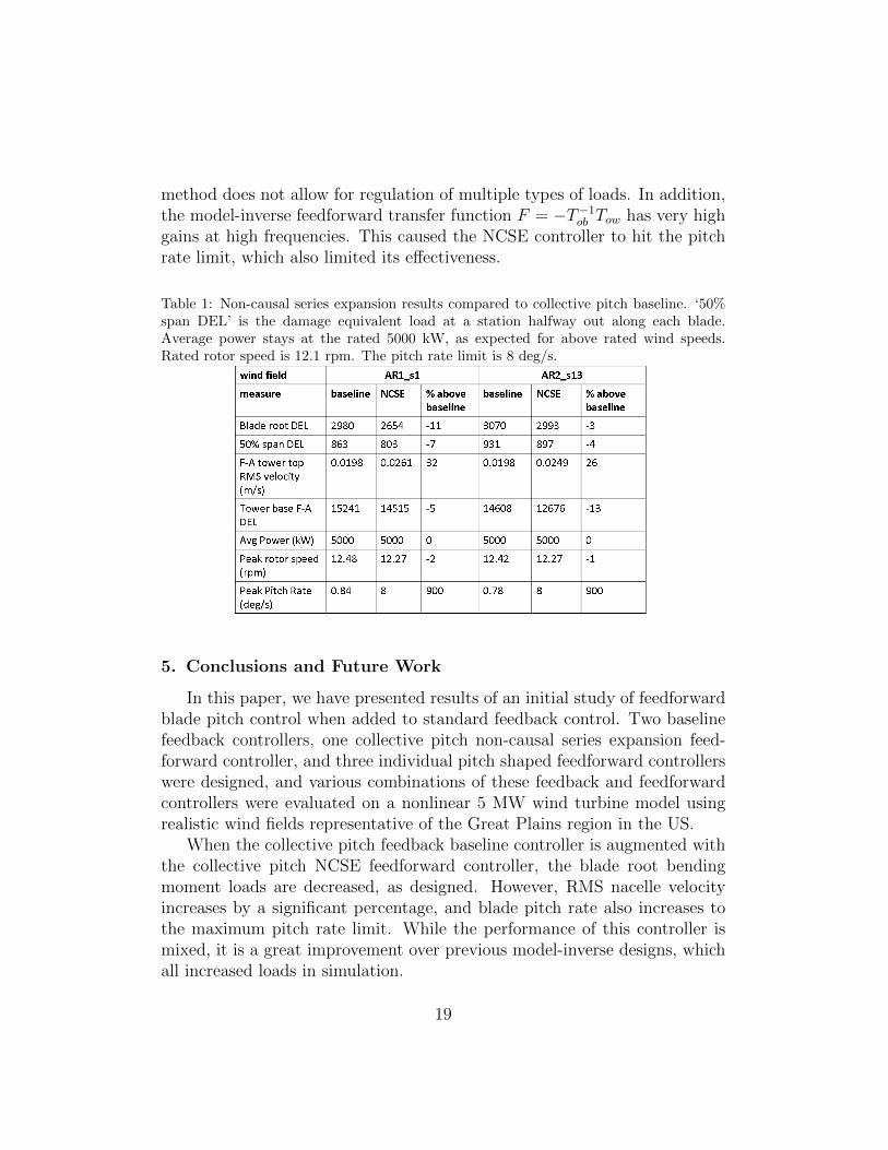
These shaped compensators work well because they allow each blade topitch as a wind speed change appears, rather than waiting for a root bendingmoment to appear and then acting to reduce it. These shaped compensatorsalso work as low pass filters, which is necessary because at high frequenciesthe point wind speed measurement used is not an accurate representation
16
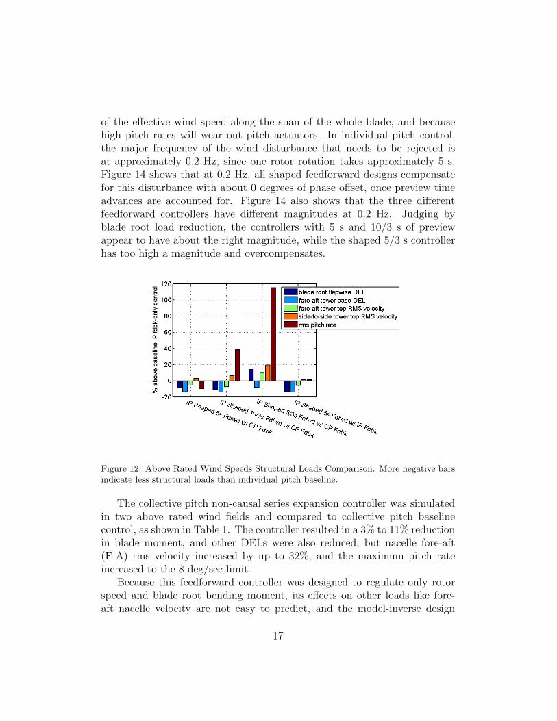
of the effective wind speed along the span of the whole blade, and becausehigh pitch rates will wear out pitch actuators. In individual pitch control,the major frequency of the wind disturbance that needs to be rejected isat approximately 0.2 Hz, since one rotor rotation takes approximately 5 s.Figure 14 shows that at 0.2 Hz, all shaped feedforward designs compensatefor this disturbance with about 0 degrees of phase offset, once preview timeadvances are accounted for. Figure 14 also shows that the three differentfeedforward controllers have different magnitudes at 0.2 Hz. Judging byblade root load reduction, the controllers with 5 s and 10/3 s of previewappear to have about the right magnitude, while the shaped 5/3 s controllerhas too high a magnitude and overcompensates.
Figure 12: Above Rated Wind Speeds Structural Loads Comparison. More negative barsindicate less structural loads than individual pitch baseline.
The collective pitch non-causal series expansion controller was simulatedin two above rated wind fields and compared to collective pitch baselinecontrol, as shown in Table 1. The controller resulted in a 3% to 11% reductionin blade moment, and other DELs were also reduced, but nacelle fore-aft(F-A) rms velocity increased by up to 32%, and the maximum pitch rateincreased to the 8 deg/sec limit.
Because this feedforward controller was designed to regulate only rotorspeed and blade root bending moment, its effects on other loads like fore-aft nacelle velocity are not easy to predict, and the model-inverse design
17
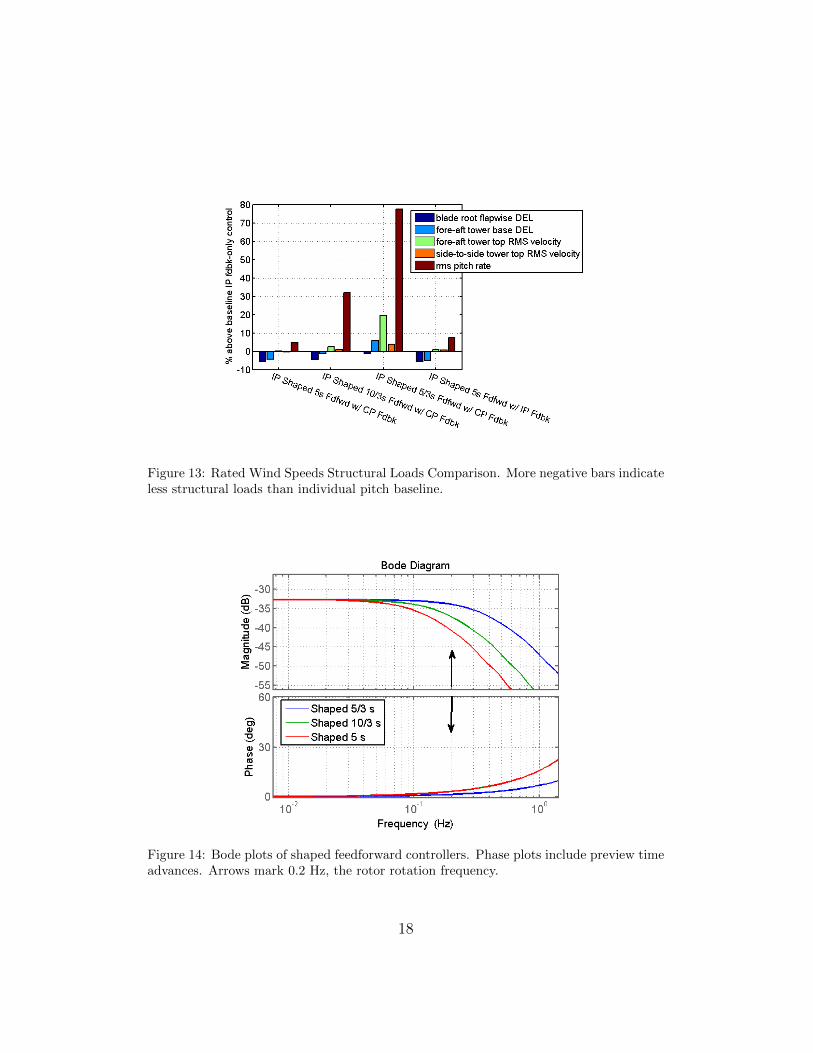
Figure 13: Rated Wind Speeds Structural Loads Comparison. More negative bars indicateless structural loads than individual pitch baseline.
Figure 14: Bode plots of shaped feedforward controllers. Phase plots include preview timeadvances. Arrows mark 0.2 Hz, the rotor rotation frequency.
18
method does not allow for regulation of multiple types of loads. In addition,the model-inverse feedforward transfer function F = −T−1
ob Tow has very highgains at high frequencies. This caused the NCSE controller to hit the pitchrate limit, which also limited its effectiveness.
Table 1: Non-causal series expansion results compared to collective pitch baseline. ‘50%span DEL’ is the damage equivalent load at a station halfway out along each blade.Average power stays at the rated 5000 kW, as expected for above rated wind speeds.Rated rotor speed is 12.1 rpm. The pitch rate limit is 8 deg/s.
5. Conclusions and Future Work
In this paper, we have presented results of an initial study of feedforwardblade pitch control when added to standard feedback control. Two baselinefeedback controllers, one collective pitch non-causal series expansion feed-forward controller, and three individual pitch shaped feedforward controllerswere designed, and various combinations of these feedback and feedforwardcontrollers were evaluated on a nonlinear 5 MW wind turbine model usingrealistic wind fields representative of the Great Plains region in the US.
When the collective pitch feedback baseline controller is augmented withthe collective pitch NCSE feedforward controller, the blade root bendingmoment loads are decreased, as designed. However, RMS nacelle velocityincreases by a significant percentage, and blade pitch rate also increases tothe maximum pitch rate limit. While the performance of this controller ismixed, it is a great improvement over previous model-inverse designs, whichall increased loads in simulation.
19

Two of the shaped individual pitch feedforward controllers show an im-provement over the individual pitch feedback-only baseline. The optimalpreview time was between 3 to 5s, but this is specific to the shaped con-troller design and may not be true in general.
A method for phasing out individual pitch control as wind speeds dropbelow rated was also developed.
Future work includes investigating other types of feedforward control ap-proaches, including H2 and Preview Control [20]. These approaches includea cost function that allows explicit minimization of rotor speed error, loads,and pitch rate. Preview control can also allow for a varying preview time,which will be advantageous because, due to various hardware implementa-tion issues, it is preferable for Lidars to be set to measure wind speeds a fixeddistance away. Therefore, the available preview time will vary as the windspeed varies. Actuator models will also be added to the turbine model, sincethese should influence the required preview time.
Acknowledgments
The authors thank Jason Jonkman for the 5 MW turbine model andHazim Namik and Karl Stol for the preliminary Simulink version of the col-lective pitch baseline controller.
This work was supported in part by the US National Renewable En-ergy Laboratory (NREL), a University of Colorado at Boulder College ofEngineering and Applied Science Dean’s Graduate Fellowship, and the USNational Science Foundation (NSF Grant CMMI-0700877). Additional in-dustrial support is also greatly appreciated.
References
[1] Bossanyi EA. Individual blade pitch control for load reduction. WindEnergy 2003;6:119–28.
[2] Stol K, Fingersh L. Wind turbine field testing of state-space controldesigns. In: NREL/SR-500-35061. 2004.
[3] Wright A, Stol K, Fingersh L. Progress in implementing and testingstate-space controls for the controls advanced research turbine. In: 24thASME Wind Energy Conference. Reno, NV; 2005, p. 88–100.
20

[4] Stol K, Zhao W, Wright A. Individual blade pitch control for the controlsadvanced research turbine (CART). ASME J Solar Energy Engineering2006;128(4):498–505.
[5] Harris M, Hand M, Wright A. Lidar for turbine control. In: NREL/TP-500-39154. 2006.
[6] Laks JH, Pao LY, Wright A. Combined feedforward/feedback control ofwind turbines to reduce blade flap bending moments. In: ProceedingsAIAA/ASME Wind Energy Symposium. Orlando, FL; 2009, p. 82–6.
[7] Laks J, Pao LY, Wright AG, Kelley N, Jonkman B. Blade pitch controlwith preview wind measurements. In: Proc. AIAA Aerospace SciencesMeeting. Orlando, FL; 2010.
[8] Laks J, Pao LY, Wright AG, Kelley N, Jonkman B. The use of previewwind measurements for blade pitch control. IFAC Journal of Mecha-tronics 2011, this issue.
[9] Schlipf D, Kuhn M. Prospects of a collective pitch control by meansof predictive disturbance compensation assisted by wind speed mea-surements. In: Proceedings of the German Wind Energy ConferenceDEWEK. 2008.
[10] Jonkman J, Buhl ML. FAST User’s Guide. Golden, CO: NationalRenewable Energy Laboratory; 2005.
[11] Jonkman J, Butterfield S, Musial W, Scott G. Definition of a 5-mwreference wind turbine for offshore system development. In: NREL/TP-500-38060. 2009.
[12] The MathWorks Inc. Simulation and model-design software package.URL http://www.mathworks.com.
[13] Kelley ND, Jonkman BJ. Overview of the Turbsim Stochastic InflowTurbulence Simulator: Version 1.21 (Revised Feb. 1, 2007). Golden,CO: National Renewable Energy Laboratory; 2007.
[14] Jonkman BJ. TurbSim User’s Guide: Version 1.50. Golden, CO: Na-tional Renewable Energy Laboratory; 2009.
21
[15] Astrom K, Hagander P, Sternby J. Zeros of sampled systems. Auto-matica 1984;20(1):31–8.
[16] Hoagg J, Bernstein D. Nonminimum-phase zeros: Much to do aboutnothing. IEEE Control Systems Magazine 2007;27:45–57.
[17] Dunne F, Pao L, Wright A, Jonkman B, Kelley N. Combining stan-dard feedback controllers with feedforward blade pitch control for loadmitigation in wind turbines. In: Proceedings of the AIAA AerospaceSciences Meeting. Orlando, FL; 2010.
[18] Butterworth J, Pao L, Abramovitch D. The effect of nonminimum-phase zero locations on the performance of feedforward model-inversecontrol techniques in discrete-time systems. In: Proc. American ControlConference. Seattle, WA; 2008, p. 2696–702.
[19] Rigney BP, Pao LY, Lawrence DA. Nonminimum phase dynamic inver-sion for settle time applications. IEEE Trans Control Systems Technol-ogy 2009;17(5):989–1005.
[20] Tomizuka M, Fung D. Design of digital feedforward/preview controllersfor processes with predetermined feedback controllers. ASME J DynSys, Meas & Ctrl 1980;102:218–25.
22
Related Documents


