PROYECTO: INGENIERIA DE DETALLE ESTACIÓN SAN FERNANDO Project : CLIENTE: ECOPETROL S.A. Client: PROYECTO NO. UNIDAD CÓDIGO DEL DOCUMENTO PROGRESIVO REVISIÓN HOJA Project No. Unit Document Code Serial No. Revision Sheet 1244_76 00 JSS 1584 01 2 1 OF 24 CÓDIGO CLIENTE: : SFD-5205306-11076-ID-INS-ET-021-2 Client Code : THIS DOCUMENT IS PROPERTY OF TIPIEL SA IT MAY NOT BE COPIED, REPRODUCED AND/OR DISTRIBUTED WITHOUT AUTHORIZATION ESTE DOCUMENTO ES PROPIEDAD DE TIPIEL SA Y NO DEBE SER COPIADO, REPRODUCIDO Y/O CIRCULADO SIN SU AUTORIZACIÓN Calle 38 No. 8 - 62 Bogotá - Colombia ADDENDUM TO Dynamic Measurement System Design Criteria San Fernando to Monterrey Pipeline MUSTANG # 16842-00-S-IE-4005 REV. C 2 02-NOV-2011 ISSUED FOR EXECUTION (REVISED AS SHOWN) L.E.GARCIA J. ESPINOSA J. ANGARITA C. PEÑA 1 30-SEP-2011 ISSUED FOR EXECUTION (REVISED AS SHOWN) H. AGUDELO J. ESPINOSA J. ANGARITA C. PEÑA 0 7-JUL-2011 ISSUED FOR EXECUTION L.E. GARCIA J. ESPINOSA J. ANGARITA C. PEÑA A 19-MAY-2011 ISSUED FOR REVIEW L.E. GARCIA J. ESPINOSA J. ANGARITA C. PEÑA REVISIÓN FECHA DE REVISIÓN DESCRIPCIÓN DE LA REVISIÓN PREPARÓ CHEQUEÓ APROBÓ AUTORIZÓ Revision Revision Date Revision Description Prepared by Checked by Approved by Authorized by

Welcome message from author
This document is posted to help you gain knowledge. Please leave a comment to let me know what you think about it! Share it to your friends and learn new things together.
Transcript

PROYECTO: INGENIERIA DE DETALLE ESTACIÓN SAN FERNANDOProject :
CLIENTE: ECOPETROL S.A.Client:
PROYECTO NO. UNIDAD CÓDIGO DEL DOCUMENTO PROGRESIVO REVISIÓN HOJAProject No. Unit Document Code Serial No. Revision Sheet
1244_76 00 JSS 1584 01 2 1 OF 24
CÓDIGO CLIENTE: : SFD-5205306-11076-ID-INS-ET-021-2Client Code :
THIS DOCUMENT IS PROPERTY OF TIPIEL SA IT MAY NOT BE COPIED, REPRODUCED AND/OR DISTRIBUTED WITHOUT AUTHORIZATIONESTE DOCUMENTO ES PROPIEDAD DE TIPIEL SA Y NO DEBE SER COPIADO, REPRODUCIDO Y/O CIRCULADO SIN SU AUTORIZACIÓN
Calle 38 No. 8 - 62 Bogotá - Colombia
ADDENDUM TO
Dynamic Measurement SystemDesign Criteria
San Fernando to Monterrey Pipeline
MUSTANG # 16842-00-S-IE-4005 REV. C
2 02-NOV-2011ISSUED FOR EXECUTION (REVISED AS
SHOWN) L.E.GARCIA J. ESPINOSA J. ANGARITA C. PEÑA
1 30-SEP-2011ISSUED FOR EXECUTION (REVISED AS
SHOWN) H. AGUDELO J. ESPINOSA J. ANGARITA C. PEÑA
0 7-JUL-2011 ISSUED FOR EXECUTIONL.E. GARCIA J. ESPINOSA J. ANGARITA C. PEÑA
A 19-MAY-2011 ISSUED FOR REVIEWL.E. GARCIA J. ESPINOSA J. ANGARITA C. PEÑA
REVISIÓN FECHA DE REVISIÓN DESCRIPCIÓN DE LA REVISIÓN PREPARÓ CHEQUEÓ APROBÓ AUTORIZÓRevision Revision Date Revision Description Prepared by Checked by Approved by Authorized by
PROYECTO: INGENIERIA DE DETALLE ESTACIÓN SAN FERNANDOProject :
CLIENTE: ECOPETROL S.A.Client:
PROYECTO NO. UNIDAD CÓDIGO DEL DOCUMENTO PROGRESIVO REVISIÓN HOJAProject No. Unit Document Code Serial No. Revision Sheet
1244_76 00 JSS 1584 01 2 2 OF 24
CÓDIGO CLIENTE: : SFD-5205306-11076-ID-INS-ET-021-2Client Code :
THIS DOCUMENT IS PROPERTY OF TIPIEL SA IT MAY NOT BE COPIED, REPRODUCED AND/OR DISTRIBUTED WITHOUT AUTHORIZATIONESTE DOCUMENTO ES PROPIEDAD DE TIPIEL SA Y NO DEBE SER COPIADO, REPRODUCIDO Y/O CIRCULADO SIN SU AUTORIZACIÓN
Calle 38 No. 8 - 62 Bogotá - Colombia
TABLE OF CONTENTS
1 INTRODUCTION.................................................................................................................................... 4
2 REFERENCES, CODES AND DEFINITIONS ....................................................................................... 4
2.1 CODES .................................................................................................................................................. 4
2.2 REFERENCES....................................................................................................................................... 5
2.4 ECOPETROL STANDARDS.................................................................................................................. 5
2.5 DEFINITIONS ........................................................................................................................................ 5
2.6 EXTENT OF SUPPLY............................................................................................................................ 6
2.6.1 Vendor´s extent...................................................................................................................................... 6
3 MEASUREMENT SYSTEMS OVERVIEW ............................................................................................ 6
3.2 FLOW METER SELECTION ALTERNATIVES ..................................................................................... 6
3.2.1 Flow Meter Selection.............................................................................................................................. 6
3.3 CUSTODY TRANSFER METERS ......................................................................................................... 6
3.8 REPORTING FUNCTIONS.................................................................................................................... 6
4 METER INSTALLATION DESCRIPTION .............................................................................................. 7
4.2 METER CONTROL INTERCONECTIONS OVERVIEW. ...................................................................... 7
5 METERING FUNCTIONAL DESCRIPTION .......................................................................................... 7
5.3 IN SERVICE........................................................................................................................................... 7
6 AUTOMATIC SAMPLING FOR CUSTODY TRANSFER METERS ...................................................... 7
6.1 AUTOMATIC SAMPLING ...................................................................................................................... 7
7 ELECTRONIC FLOW COMPUTER....................................................................................................... 7
7.2 HARDWARE REQUIREMENTS............................................................................................................ 7
7.2.1 Cabinets ................................................................................................................................................. 7
7.2.2 Prover I/O............................................................................................................................................... 9
7.2.3 Flow computer Communication Interfaces............................................................................................. 9
7.3 SOFTWARE REQUIREMENTS...........................................................................................................10
8 DISPLACEMENT PROVER.................................................................................................................10
8.2 BIDIRECTIONAL PIPE PROVER. .......................................................................................................10
8.2.1 Bidirectional Sphere Prover. ................................................................................................................10
9 INSTALLATION REQUIREMENTS FOR METERING INSTRUMENTATION.....................................12
9.1 SKID REQUIREMENTS.......................................................................................................................12
9.1.1 Instrument Air.......................................................................................................................................12
9.1.2 Piping ...................................................................................................................................................13
9.1.3 Drain & Vent.........................................................................................................................................13
9.1.4 Strainer.................................................................................................................................................13
9.1.5 Skid Access..........................................................................................................................................13
9.2 ELECTRICAL REQUIREMENTS.........................................................................................................13
9.2.1 General ................................................................................................................................................13
9.2.2 Electrical Systems Assembly ...............................................................................................................14
9.2.3 Terminal Block Requirements..............................................................................................................14
9.2.4 Wiring ...................................................................................................................................................15
9.2.5 Cabinet Power Supply .........................................................................................................................16
9.2.6 Grounding ............................................................................................................................................16

PROYECTO: INGENIERIA DE DETALLE ESTACIÓN SAN FERNANDOProject :
CLIENTE: ECOPETROL S.A.Client:
PROYECTO NO. UNIDAD CÓDIGO DEL DOCUMENTO PROGRESIVO REVISIÓN HOJAProject No. Unit Document Code Serial No. Revision Sheet
1244_76 00 JSS 1584 01 2 3 OF 24
CÓDIGO CLIENTE: : SFD-5205306-11076-ID-INS-ET-021-2Client Code :
THIS DOCUMENT IS PROPERTY OF TIPIEL SA IT MAY NOT BE COPIED, REPRODUCED AND/OR DISTRIBUTED WITHOUT AUTHORIZATIONESTE DOCUMENTO ES PROPIEDAD DE TIPIEL SA Y NO DEBE SER COPIADO, REPRODUCIDO Y/O CIRCULADO SIN SU AUTORIZACIÓN
Calle 38 No. 8 - 62 Bogotá - Colombia
9.2.7 Nameplates and Tagging.....................................................................................................................16
10 INSPECTION AND TESTING REQUIREMENTS................................................................................17
11 ANNEXES ............................................................................................................................................17
APPENDIX A – PROCESS DESIGN DATA...........................................................................................................18
APPENDIX B – INSTRUMENT REQUIREMENTS FOR METER INSTALLATIONS.............................................19

PROYECTO: INGENIERIA DE DETALLE ESTACIÓN SAN FERNANDOProject :
CLIENTE: ECOPETROL S.A.Client:
PROYECTO NO. UNIDAD CÓDIGO DEL DOCUMENTO PROGRESIVO REVISIÓN HOJAProject No. Unit Document Code Serial No. Revision Sheet
1244_76 00 JSS 1584 01 2 4 OF 24
CÓDIGO CLIENTE: : SFD-5205306-11076-ID-INS-ET-021-2Client Code :
THIS DOCUMENT IS PROPERTY OF TIPIEL SA IT MAY NOT BE COPIED, REPRODUCED AND/OR DISTRIBUTED WITHOUT AUTHORIZATIONESTE DOCUMENTO ES PROPIEDAD DE TIPIEL SA Y NO DEBE SER COPIADO, REPRODUCIDO Y/O CIRCULADO SIN SU AUTORIZACIÓN
Calle 38 No. 8 - 62 Bogotá - Colombia
1 INTRODUCTION
This document will be used as General design and supply rules for dynamic measurement systems (LACTunits) in San Fernando Pump Station.
The content of this Addendum to Mustang engineering standard “Dynamic Measurement San Fernando toMonterrey Pipeline” doc. No. 16842-00-S-IE-4005, shall be applied in addition as part of “Ingeniería deDetalle Estación San Fernando”.
This document modifies Mustang standard identifying as Add to add a specific text, Delete to delete textthat is considered not applicable and Modify to change specific words (In bold to add and strikethroughto delete) in a paragraph from Mustang Standard.
2 REFERENCES, CODES AND DEFINITIONS
2.1 CODES
Add
API MPMS Chapter 6 Section 1 Lease Automatic Custody Transfer (LACT) Systems
API MPMS Chapter 10 Sediment and Water.
API MPMS Chapter 13 Statistical Aspects of Measurement and Sampling.
API MPMS Chapter 14 Section 6 Continuous Density Measurement.
API MPMS Chapter 14 Section 8 Liquefied Petroleum Gas Measurements.
API MPMS Chapter 17 Section 1 Guidelines for Marine Cargo Inspection.
API MPMS Chapter 18 Custody Transfer.
API MPMS Chapter 20 Section 1 Allocation Measurement.
API 600 Steel gate valves.
API 601 Metallic gaskets for piping double-jacketedcorrugated and spiral wound.
API 602 Compact steel gate valve.
API 1104 Standard for Welding Pipelines and RelatedFacilities.
API RP 500 Recommended Practice for Classification ofLocations for Electrical Installation at PetroleumFacilities.
API RP 520 Sizing Selection and Installation of Pressure-Relieving Devices in Refineries.
API RP 521 Guide for Pressure-Relieving and DepressuringSystem.
API RP 526 Flanged Steel Pressure Relief Valves.
API RP 527 Seat Tightness of Pressure Relief Valves.
API RP 551 Process Measurement Instrumentation.
API RP 552 Transmission Systems.
API RP 555 Analizadores

PROYECTO: INGENIERIA DE DETALLE ESTACIÓN SAN FERNANDOProject :
CLIENTE: ECOPETROL S.A.Client:
PROYECTO NO. UNIDAD CÓDIGO DEL DOCUMENTO PROGRESIVO REVISIÓN HOJAProject No. Unit Document Code Serial No. Revision Sheet
1244_76 00 JSS 1584 01 2 5 OF 24
CÓDIGO CLIENTE: : SFD-5205306-11076-ID-INS-ET-021-2Client Code :
THIS DOCUMENT IS PROPERTY OF TIPIEL SA IT MAY NOT BE COPIED, REPRODUCED AND/OR DISTRIBUTED WITHOUT AUTHORIZATIONESTE DOCUMENTO ES PROPIEDAD DE TIPIEL SA Y NO DEBE SER COPIADO, REPRODUCIDO Y/O CIRCULADO SIN SU AUTORIZACIÓN
Calle 38 No. 8 - 62 Bogotá - Colombia
API Standard 599 Metal Plug Valves - Flanged and Welding Ends.
API Standard 609 Lug and Wafer Type Butterfly Valves.
API Spec 6D Specification for Pipeline Valves.
API Spec 6FA Specification for Fire Test for Valves.
API 5L Specification for Line Pipe.
2.2 REFERENCES
Add
16842-00-S-IE-4016 Rev B Prover Data Sheets
16842-00-S-ME-8014 Rev C Filter Meter Package Specification
1244_76-00-JSD-1540-01_0 Addendum to Instrumentation Design Basis SanFernando to Monterrey Pipeline
1244_76-00-DW-1576-08 _A Típicos Eléctricos de Instrumentos
1244_76-00-DW-1576-01_A Típicos Neumáticos de Instrumentos
2.4 ECOPETROL STANDARDS
Add
ECP-VST-P-INS-ET-018 Version 1 Estándar de Ingeniería para la Medición Dinámica deCantidad y Calidad de Hidrocarburos Líquidos
ECP-DAB-F-366 Version 2 Lista de marcas aceptadas – Equipos de mediciónpara transferencia en custodia.
2.5 DEFINITIONS
Add
CONTRACTOR Company that presents the purchase order
VENDOR The party that carries out and/or supplies equipment,materials, goods and/or services for the Machinery orPackaged Unit of the project.
MANUFACTURER VENDOR itself or any Vendor sub-suppliermanufacturing a specifiedmaterial/equipment/device/system included in thescope of supply of the Machinery or Packaged Unit.
<2>

PROYECTO: INGENIERIA DE DETALLE ESTACIÓN SAN FERNANDOProject :
CLIENTE: ECOPETROL S.A.Client:
PROYECTO NO. UNIDAD CÓDIGO DEL DOCUMENTO PROGRESIVO REVISIÓN HOJAProject No. Unit Document Code Serial No. Revision Sheet
1244_76 00 JSS 1584 01 2 6 OF 24
CÓDIGO CLIENTE: : SFD-5205306-11076-ID-INS-ET-021-2Client Code :
THIS DOCUMENT IS PROPERTY OF TIPIEL SA IT MAY NOT BE COPIED, REPRODUCED AND/OR DISTRIBUTED WITHOUT AUTHORIZATIONESTE DOCUMENTO ES PROPIEDAD DE TIPIEL SA Y NO DEBE SER COPIADO, REPRODUCIDO Y/O CIRCULADO SIN SU AUTORIZACIÓN
Calle 38 No. 8 - 62 Bogotá - Colombia
Add
2.6 EXTENT OF SUPPLY
2.6.1 Vendor´s extent
The vendor shall perform all the detail engineering, including the data sheets for all the skids instrumentation,cabinets, electrical accessories and connections. Besides Vendor shall give the piping and mechanicallayouts, in order to carry out the construction, assembling, pre-commissioning, commissioning and start up onfield.
The Vendor shall supply two (2) complete Dynamic Measurement Systems to measure the crude oil inflowfrom Chichimene (LACT-2301) and Castilla (LACT-3301) stations, mounted on skid at San Fernando stationwith a 165 KBD and 242 KBD maximum flow capacity respectively.
3 MEASUREMENT SYSTEMS OVERVIEW
3.2 FLOW METER SELECTION ALTERNATIVES
Add
3.2.1 Flow Meter Selection.
TIPIEL S.A recommends double case positive displacement meters for this application, however, Vendorshould recommend another technology if Vendor considers a better technical solution, according to processconditions.
3.3 CUSTODY TRANSFER METERS
Modify
Custody transfer meters shall be designed and built in accordance with API MPMS measurement standardsfor the type of meter and proving system specified for the specific meter installation, and will be provided withhigh accuracy temperature and pressure measurement instrumentation, meter prover, densitometer,viscometer, automatic sampling and BSW meter.
3.8 REPORTING FUNCTIONS.
Delete
There will not be a printer directly connected to the flow computer. All reports will be produced from datacommunicated over network connection to the PCS. However, the flow computer must have the capability ofbeing directly connected to a printer should the need arise in the future.
Add
Vendor shall furnish a dedicated printer to be directly connected to the flow computer. The flow computermust have the capability to be directly connected to the printer.
<2>

PROYECTO: INGENIERIA DE DETALLE ESTACIÓN SAN FERNANDOProject :
CLIENTE: ECOPETROL S.A.Client:
PROYECTO NO. UNIDAD CÓDIGO DEL DOCUMENTO PROGRESIVO REVISIÓN HOJAProject No. Unit Document Code Serial No. Revision Sheet
1244_76 00 JSS 1584 01 2 7 OF 24
CÓDIGO CLIENTE: : SFD-5205306-11076-ID-INS-ET-021-2Client Code :
THIS DOCUMENT IS PROPERTY OF TIPIEL SA IT MAY NOT BE COPIED, REPRODUCED AND/OR DISTRIBUTED WITHOUT AUTHORIZATIONESTE DOCUMENTO ES PROPIEDAD DE TIPIEL SA Y NO DEBE SER COPIADO, REPRODUCIDO Y/O CIRCULADO SIN SU AUTORIZACIÓN
Calle 38 No. 8 - 62 Bogotá - Colombia
4 METER INSTALLATION DESCRIPTION
4.2 METER CONTROL INTERCONECTIONS OVERVIEW.
Add
The communication between the flow computer and the Process Control system shall be MODBUS TCP/IP.
5 METERING FUNCTIONAL DESCRIPTION
5.3 IN SERVICE.
Modify
During in-service operation, the FC balances flow through the meters to maintain operation at the optimalpoint for metered accuracy and meter wear. Positive displacement meters will typically operate between 25%and a maximum 80% of rated capacity. Optimal operation for positive displacement meters is approximately75% of range.
6 AUTOMATIC SAMPLING FOR CUSTODY TRANSFER METERS
6.1 AUTOMATIC SAMPLING
Modify
Meter installations with automatic sample systems shall also be furnished with the facility for manualsampling, according to the requirements of API MPS 8.1, for use in the event the automatic samplesystem is inoperable or requires maintenance.
7 ELECTRONIC FLOW COMPUTER
7.2 HARDWARE REQUIREMENTS
Add
Each Dynamic Measurement System designed to measure the crude oil inflow from Chichimene (LACT-2301) and Castilla (LACT-3301) shall have its independent, standalone flow computer.
7.2.1 Cabinets
NOTE: It is not the intent of this specification to completely specify all details of design and construction.Suggested changes to these specifications which improve the installation, operation, or effect economy offabrication at not sacrifice in performance or quality will be considered, provided suitable notification is madein the quotation. This specification shall not eliminate considerations of Vendor’s factory practice, which mayreceive approval if found equivalent or superior to the requirements covered in this specification.
Each Dynamic Measurement Systems shall include one (1) Flow Computer (Flow computer redundancy isnot required). Communication between Flow computers and BPCS shall be through MODBUS TCP/IP, flowcomputers shall have minimum two MODBUS TCP/IP ports. Each Flow Computer shall have a 12 digits totalcounter on the display.
<2>

PROYECTO: INGENIERIA DE DETALLE ESTACIÓN SAN FERNANDOProject :
CLIENTE: ECOPETROL S.A.Client:
PROYECTO NO. UNIDAD CÓDIGO DEL DOCUMENTO PROGRESIVO REVISIÓN HOJAProject No. Unit Document Code Serial No. Revision Sheet
1244_76 00 JSS 1584 01 2 8 OF 24
CÓDIGO CLIENTE: : SFD-5205306-11076-ID-INS-ET-021-2Client Code :
THIS DOCUMENT IS PROPERTY OF TIPIEL SA IT MAY NOT BE COPIED, REPRODUCED AND/OR DISTRIBUTED WITHOUT AUTHORIZATIONESTE DOCUMENTO ES PROPIEDAD DE TIPIEL SA Y NO DEBE SER COPIADO, REPRODUCIDO Y/O CIRCULADO SIN SU AUTORIZACIÓN
Calle 38 No. 8 - 62 Bogotá - Colombia
The cabinet must be pre wired with terminal fuses and switches for testing. The Cabinet shall have enoughroom to lodge in the flow computers, the electrical devices (I/O terminals, Power supplies, display, indicationlights, and buttons). At least two electrical connections, one main and another one for spare, to power up theflow computer cabinet with 120 VAC 60 Hz from UPS. Cabinet will be installed outdoor in classified areaClass I Div 2 Group D T2A. Cabinet shall be self-standing, IP 66 type, equipped with a thermostaticallycontrolled anti-condensation heater, vortex cooler and Z type pressurization. Wiring shall be arranged so asto be readily accessible for inspection and maintenance, and in no case shall wiring arrangement impedeaccess to panel mounted devices or spaces for future equipment.
The cabinet in which the electronics will be installed, shall be duly identified by a stainless steel plate,permanently attached, stamped with the equipment tag number. In outdoor plant areas, the cabinet enclosureshall be IEC 60529 Type IP66, manufactured of 316L stainless steel. Galvanized and/or painted or coatedcarbon steel sheet metal enclosures are not permitted.
The panel/cabinet and all components within the panel shall be suitable for the electrical area classificationwhere the panel will be installed: Class I Div 2 Group D T2A. Z purge pressurization shall be used and localpanels shall have an audible and visual alarm for depressurization.
The local panel’s design must allow full and easy access to all components, connections, terminations, andassemblies by installation, maintenance and repair personnel. All cabinets supplied by VENDOR shall be fullyequipped/wired (frames and racks, terminal strips and rail, wire markers and ferrules, etc). Modules shall bemounted on cabinet front part and terminals shall be mounted on cabinet rear part. The cable entry shall beon cabinet bottom part.
Galvanized intrinsically barriers shall be installed on local panel.
Relays shall be hermetically sealed
Pushbuttons, pilot lights and switches shall be heavy duty, oil-tight, and shall meet the area classification ofthe installed location.
Cabinet lights and convenience outlets shall be provided. At least one light and duplex outlet shall beprovided for each cabinet.
Vortex cooler system shall be provided for each cabinet.
All devices installed in field shall be tropicalized.
Vendor shall be responsible for the detailed panel/cabinet and framing design. The panel shall have:
- Terminal strip with terminal connectors for analogue signals as required.- Redundant Power supply suitable for the Area Classification with the characteristics described at
section 9.2.5.- 14 caliber sheet, 316L stainless steel bodies and doors- Seams continuously welded and ground smooth, no holes or knockouts- Seamless foam-in-place gasket to assure watertight and dust-tight seal- Body stiffener to provide extra rigidity- Rolled lip around three sides of door and all sides of enclosure opening to excludes liquids and
contaminants- Stainless steel door clamp assembly to assures watertight seal- A padlocking with hasp and staple- Frontal door supported to enclosure with stainless steel continuous hinge and pins- Data pocket with high impact thermoplastic- Collar studs provided for mounting optional panels- Fluorescent lighting and ventilation fan (only if required).- Vortex cooler

PROYECTO: INGENIERIA DE DETALLE ESTACIÓN SAN FERNANDOProject :
CLIENTE: ECOPETROL S.A.Client:
PROYECTO NO. UNIDAD CÓDIGO DEL DOCUMENTO PROGRESIVO REVISIÓN HOJAProject No. Unit Document Code Serial No. Revision Sheet
1244_76 00 JSS 1584 01 2 9 OF 24
CÓDIGO CLIENTE: : SFD-5205306-11076-ID-INS-ET-021-2Client Code :
THIS DOCUMENT IS PROPERTY OF TIPIEL SA IT MAY NOT BE COPIED, REPRODUCED AND/OR DISTRIBUTED WITHOUT AUTHORIZATIONESTE DOCUMENTO ES PROPIEDAD DE TIPIEL SA Y NO DEBE SER COPIADO, REPRODUCIDO Y/O CIRCULADO SIN SU AUTORIZACIÓN
Calle 38 No. 8 - 62 Bogotá - Colombia
Electronic modules shall be mounted in racks and shall be firmly secured. Internal layout of cubicles shall bedesigned to provide unimpeded access to all electronic modules, power distribution switches, fuses, terminalsand field cable termination areas. Blanking plates shall be fitted where modules or racks are not present.
The required spare for cabinet, cabinet hardware and software are:
- 30 % Free volume inside cabinets (suitable to accommodate future additionalHardware);
- 30% Electronic components installed and wired, to be used only for future needs;
- 50% Extra capacity of specific components (as CPU’s, Power Supply Units, BufferMemory, etc.) to assure that their “rated capacity” will not be exceeded duringnormal operation.
The required extra capacity shall be kept available for possible flow computer future expansions.
7.2.2 Prover I/O
For this project, prover will be shared by Chichimene and Castilla LACT units. Prover doesn’t require anindependent flow computer, I/O for prover shall be integrated in Chichimene and/or Castilla flow computersaccording to following recommendations:
a. Prover temperature, pressure and switches signals: Vendor have two different options to send thesesignals to each flow computer:
- First Option: Prover temperature, pressure and switches signals shall be shared to each flowcomputer (in series or parallel), this means that each flow computer shall have the required I/O toreceive all required signals from the prover.
- Second Option: Prover temperature, pressure and switches signals shall be connected to justone flow computer and they will be transmitted to the other flow computer using acommunications highway. In this case, I/O channels for prover signals shall be required just inone flow computer and dedicated communication ports for sharing these signals shall beprovided in all flow computers.
b. 4 Ways diverter valve (bidirectional prover) or solenoid valve (compact prover) command signal: SanFernando Station Basic Process Control System will run a dedicated logic to ensure that just one flowcomputer performs calibration and controls the 4 ways valve/solenoid, Vendor shall supply hardwareand logic configuration required to execute this action.
7.2.3 Flow computer Communication Interfaces
Each flow computer shall be connected to Basic Process Control System (BPCS) using a communicationport. This communication port shall be a redundant Ethernet link (Modbus over TCP/IP) on fiber optic. Eachcommunication port shall be on a separate module. The flow computer internal date and time clock shall besynchronized with BPCS clock through the MODBUS TCP/P link. VENDOR shall supply all necessaryaccessories (Patch panels, media converters, switches, etc.) to warrantee the communication via fiber optic.All communication active devices (model and manufacturer) shall be approved by ECOPETROL beforepurchase.
The VENDOR shall state all standard Manufacturer protocols supported by the system and their operationalpossibilities. All data links shall provide secure transmission with data transfer error detection, self-diagnosisand retry facilities. Detected errors and faults shall initiate an alarm
<2>
<2>

PROYECTO: INGENIERIA DE DETALLE ESTACIÓN SAN FERNANDOProject :
CLIENTE: ECOPETROL S.A.Client:
PROYECTO NO. UNIDAD CÓDIGO DEL DOCUMENTO PROGRESIVO REVISIÓN HOJAProject No. Unit Document Code Serial No. Revision Sheet
1244_76 00 JSS 1584 01 2 10 OF 24
CÓDIGO CLIENTE: : SFD-5205306-11076-ID-INS-ET-021-2Client Code :
THIS DOCUMENT IS PROPERTY OF TIPIEL SA IT MAY NOT BE COPIED, REPRODUCED AND/OR DISTRIBUTED WITHOUT AUTHORIZATIONESTE DOCUMENTO ES PROPIEDAD DE TIPIEL SA Y NO DEBE SER COPIADO, REPRODUCIDO Y/O CIRCULADO SIN SU AUTORIZACIÓN
Calle 38 No. 8 - 62 Bogotá - Colombia
7.3 SOFTWARE REQUIREMENTS
Modify
The data base must have MODBUS communication tables (database with Modbus ID) with all systemvariables, which shall be furnished by the Vendor.
Modify
Acceptable Flow Computer Vendor:
Emerson Daniel Model S600 Omni Smith meter (FMC) Thermofisher Top Tech System
According to ECOPETROL Vendor List.
8 DISPLACEMENT PROVER
Add
TIPIEL recommends, the Bidirectional Pipe Prover as the best alternative for this application. However,Vendor can recommend a different technology if it consider a better technical solution, according to processconditions.
8.2 BIDIRECTIONAL PIPE PROVER.
Add
The following characteristics for bidirectional pipe prover are extracted from ECOPETROL document ECP-VSM-I-001, section 7.2.9.1.
8.2.1 Bidirectional Sphere Prover.
Designing measurement system, engineers must select relevant accessories for metrological assurance oftheir system; this design shall include important accessories for provers.
The prover shall have proper connections and easy access for calibration by "Water Draw" method. Inaddition, the prover shall have thermal isolation with either insulation material or suitable painting.
The prover shall be constructed in accordance with API MPMS Chapter 4.2 “Proving Systems - DisplacementProvers " and based on the following criteria and minimum accessories:
All new prover must have installed four (4) sphere switch detectors (two on each end) and two (2)certified calibrated volumes. Volume calibration between the two pairs of detectors should besufficient to allow identification of the pair of detectors that are being used (the difference in volumescalibrated must be no more than 0.05%).
The velocity of displacer depends on the internal diameter of the pipe prover and maximum andminimum flow meter to be calibrated. The speed of the displacer can be calculated as follows:
Velocity = Flow rate / Piping area.

PROYECTO: INGENIERIA DE DETALLE ESTACIÓN SAN FERNANDOProject :
CLIENTE: ECOPETROL S.A.Client:
PROYECTO NO. UNIDAD CÓDIGO DEL DOCUMENTO PROGRESIVO REVISIÓN HOJAProject No. Unit Document Code Serial No. Revision Sheet
1244_76 00 JSS 1584 01 2 11 OF 24
CÓDIGO CLIENTE: : SFD-5205306-11076-ID-INS-ET-021-2Client Code :
THIS DOCUMENT IS PROPERTY OF TIPIEL SA IT MAY NOT BE COPIED, REPRODUCED AND/OR DISTRIBUTED WITHOUT AUTHORIZATIONESTE DOCUMENTO ES PROPIEDAD DE TIPIEL SA Y NO DEBE SER COPIADO, REPRODUCIDO Y/O CIRCULADO SIN SU AUTORIZACIÓN
Calle 38 No. 8 - 62 Bogotá - Colombia
Where:
= Flow rat of barrels per hour
= Pipe inside diameter in inches of prover
= Speed displacer in ft/sec
For more details on sizing and calculation examples of provers refer to Appendix B of API MPMSChapter 4.2.
Some manufacturers recommend using a displacer design speed of 3.75 ft/sec and a maximumspeed of 5 ft/sec, to provide for future growth. The minimum speed shall be not less than 0.5 ft/sec.
Flanges on the calibrated section must be Female-Male (with packing O-ring) type, being able to bedisarmed if an internal review of calibrated section is needed or to transport to preserve thecalibrated section.
Several types of sensing switches displacer are described below:
a. Mechanical type, which can be used to detect the passage of spheres built with elastomersand pistons and can turn on the switch in mechanical or magnetic way and also can bedesigned balanced for pressure.
b. Proximity type magnetic actuation, bidirectional provers are used in piston rings and 2 non-magnetic drivers are built into the piston seals.
c. Optically actuated when a switch element passes between a photocell and a light source,commonly used in compact provers or small volume provers.
Optical actuated sensing switches are the preferred option; however Vendor shall recommend thebest practice for this application.
Thermal relief valve normally installed in the outlet pipe of the prover.
Displacer Switches. They are high precision devices installed in the prover, which are used todetect the passage of the displacer; the volume Certified of prover is an amount of fluid that isdisplaced by 2 position detectors switches. Additional switches can be installed and used if morethan a calibrated volume is required in the same prover, they can also be used to mark the entranceor exit of the displacer to the sphere rest chamber of the area within the launch chamber.
Launching and Receiver chambers. The prover must be foreseen with an area for the displacer torest when it is not in use. Bidirectional sphere provers require launching chambers at both ends, thebidirectional piston provers do not require launching chambers.
4-way diverter valve. It used in bidirectional provers (sphere and piston), it serves to change theflow direction. They are designed to generate low pressure differentials; they shall be double blockand bleed to verify the integrity of the valve seal. A hermetic seal must be guaranteed and verifiedbefore the sphere activates the first detector. An additional length of pipe must be incorporated to theprover (pipe race agreement), between the launch chamber and sphere detectors, to allow spheretrip while the valve is changing track and to ensure it is completely closed before sphere makescontact with the first switch This length is designed for maximum flow rate to be handled by theprover. 4-way diverter valve shall have electric or electro-hydraulic actuator, depending on valve size,controlled from flow computer. It shall have in its body pressure gauge and differential pressuretransmitter, which permit supervising the seal valve during meters calibration. Valve position limitswitches shall be connected to the flow computer.

PROYECTO: INGENIERIA DE DETALLE ESTACIÓN SAN FERNANDOProject :
CLIENTE: ECOPETROL S.A.Client:
PROYECTO NO. UNIDAD CÓDIGO DEL DOCUMENTO PROGRESIVO REVISIÓN HOJAProject No. Unit Document Code Serial No. Revision Sheet
1244_76 00 JSS 1584 01 2 12 OF 24
CÓDIGO CLIENTE: : SFD-5205306-11076-ID-INS-ET-021-2Client Code :
THIS DOCUMENT IS PROPERTY OF TIPIEL SA IT MAY NOT BE COPIED, REPRODUCED AND/OR DISTRIBUTED WITHOUT AUTHORIZATIONESTE DOCUMENTO ES PROPIEDAD DE TIPIEL SA Y NO DEBE SER COPIADO, REPRODUCIDO Y/O CIRCULADO SIN SU AUTORIZACIÓN
Calle 38 No. 8 - 62 Bogotá - Colombia
Pressure and temperature transmitters, calibrated pressure gauges, Thermowells to certifiedthermometers in the inlet and outlet prover and 2 additional thermowell for the input and outputverification process loop temperature.
Spare parts in sufficient quantities for commissioning and two years operation and accessoriesrequired for proper operation and supervision, such as: spheres, kit inflation / filling, ring sizing andremoval kit, tabs for 4-way valve and sphere detector switches.
At least one quick-opening cover (installed in one of the sphere launching chamber), with pressureindicating device, capable of covering the maximum pressure system.
Vent valve in the highest points of the launching chambers.
Drain valves in the lowest points out of the calibrated section and in the launching chambers.
Permanent Connections for re-calibration in the field, by the Water Draw method.
Spheres: Inflatable spheres generally can be of three types of Materials:
- Neoprene Spheres. are good for low-pressure oil Applications and anhydrous ammonia. Notrecommended for the presence of aromatic products. They are black color.
- Nitrile Spheres. . They are used in petroleum products applications (Gasoline, kerosene,diesel, etc.) And high pressure crude. They are black color.
- Polyurethane spheres: They are more resistant to abrasion than those mentioned above. Theyare distinguished by the following colors:
Yellow (durometer 53). For applications of sweet crude, gasoline, hot oil, Jet A1, Avigas,butane, propane, natural gas liquids and all refined products not classified as aromatic.
Green (durometer 58). For applications of high pressure natural gas.
Red (durometer 66). For applications with toluene, propylene and where some compoundstend to cause blisters and cause damage to the sphere
The inflated size of the spheres is covered by API MPMS Chapter 4.2, Appendix F, called"Prover Sphere sizing" in order to obtain an inflated minimum guarantee seal when faced withswitches displacer detectors or pipe prover accessories.
Vendor shall select the adequate sphere type according to process data. In addition, theVendor shall furnish sphere calibration kit and the required accessories to remove sphere fromprover.
9 INSTALLATION REQUIREMENTS FOR METERING INSTRUMENTATION
Add
9.1 SKID REQUIREMENTS
9.1.1 Instrument Air.
Vendor shall provide an instrument air header of one-inch pipe. Refer to piping class specifications. Theheader shall be terminated at the skid edge with a 1-inch ball valve. Sub-headers shall branch from the airheader with a 1/2-inch gate valve and Swagelok male connector. A separate branch is required for eachinstrument loop.

PROYECTO: INGENIERIA DE DETALLE ESTACIÓN SAN FERNANDOProject :
CLIENTE: ECOPETROL S.A.Client:
PROYECTO NO. UNIDAD CÓDIGO DEL DOCUMENTO PROGRESIVO REVISIÓN HOJAProject No. Unit Document Code Serial No. Revision Sheet
1244_76 00 JSS 1584 01 2 13 OF 24
CÓDIGO CLIENTE: : SFD-5205306-11076-ID-INS-ET-021-2Client Code :
THIS DOCUMENT IS PROPERTY OF TIPIEL SA IT MAY NOT BE COPIED, REPRODUCED AND/OR DISTRIBUTED WITHOUT AUTHORIZATIONESTE DOCUMENTO ES PROPIEDAD DE TIPIEL SA Y NO DEBE SER COPIADO, REPRODUCIDO Y/O CIRCULADO SIN SU AUTORIZACIÓN
Calle 38 No. 8 - 62 Bogotá - Colombia
9.1.2 Piping
All piping will terminate at skid edge and sufficiently braced to the skid to prevent damage during shipmentand normal operation. All materials, piping fittings shall be according to the piping class. All the material shallbe according with the piping class.
9.1.3 Drain & Vent.
All drain/vents inlet/ outlet end connections shall be flanged. Vendor shall design all required drains andvents, with its required vent/drain header. Drains (branches and header) size will be directly related to theproducts hydraulic calculation to be done by Vendor.
Skid Drains located downstream the flow meter should be reduced to a minimum and shall have CSOvalves (Car sealed Open Valve).
9.1.4 Strainer
In order to filter out foreign materials such as sand, rust, scale, welding beads, slag, and gravel, that candamage the flow meter, it’s necessary to install, upstream of the meter in each arm, a device filter to protectthe meter. This will include a basket filter or barrier that stops foreign matter that may affect the properfunctioning of the meter. The Vendor shall specify the appropriate strainer mesh size to protect the meter.The Strainer shall have a differential pressure transmitter that will be connected to BPCS with a high alarmconfigured.A means of manual venting should be provided at strategic locations so that air or vapor can be releasedduring start-up and after maintenance.
9.1.5 Skid Access
The skid measurement areas shall have adequate access facilities. Each measurement arm must haveenough space for inspection and maintenance, considering ergonomic, safety, pipe dimensions and accessrequirements.
9.2 ELECTRICAL REQUIREMENTS
9.2.1 General
All wiring leaving the skid shall terminate in the junction boxes furnished by the Vendor and mounted on theskid boundary. The junction box shall be comprised of the necessary hardware to handle all instrumentationsignals from/to skid. It will also receive the signals from the instruments installed in the “quality loop”.
The junction box for instruments signals shall have NEMA 4X certification. Terminal blocks shall be EEx-ecertified and shall be built with non-burning thermoplastic.
The junction boxes shall be in concordance with Tipiel document 1244_76-00-JSS-1575-01 “GENERALSUPPLY RULES FOR JUNCTION BOXES”.
Separate junction boxes shall be furnished to terminate circuits as follows:
- Low voltage signals from RTD (if applicable), pulsed output from flow meters and Communicationssignals
- Hart or 4-20 mA for pressure and temperature transmitters and digital signals in separate terminalblocks

PROYECTO: INGENIERIA DE DETALLE ESTACIÓN SAN FERNANDOProject :
CLIENTE: ECOPETROL S.A.Client:
PROYECTO NO. UNIDAD CÓDIGO DEL DOCUMENTO PROGRESIVO REVISIÓN HOJAProject No. Unit Document Code Serial No. Revision Sheet
1244_76 00 JSS 1584 01 2 14 OF 24
CÓDIGO CLIENTE: : SFD-5205306-11076-ID-INS-ET-021-2Client Code :
THIS DOCUMENT IS PROPERTY OF TIPIEL SA IT MAY NOT BE COPIED, REPRODUCED AND/OR DISTRIBUTED WITHOUT AUTHORIZATIONESTE DOCUMENTO ES PROPIEDAD DE TIPIEL SA Y NO DEBE SER COPIADO, REPRODUCIDO Y/O CIRCULADO SIN SU AUTORIZACIÓN
Calle 38 No. 8 - 62 Bogotá - Colombia
All wiring shall comply with the NEC (National Electric Code). Without exception, all devices, materials,equipment, and assemblies, which are electrical or contain electrical components shall be UL (Underwriters'Laboratory) or FM (Factory Mutual) approved, or meets UL specifications where approval has not beenobtained.
Compliance with one of the above certification requirements is mandatory for all electrical items and noexceptions will be allowed. The Vendor is encouraged to recommend equivalent alternative UL, FM, or CSAlisted products to replace any BUYER-specified products, which are not UL, FM, or CSA listed. The Vendor'sunderstanding of these requirements must be acknowledged in his proposal.
All the transmitters and the flow meters associated to the dynamic measurement system shall be 24 VDCloop powered.
9.2.2 Electrical Systems Assembly
Vendor shall furnish and mount all DC sources, breakers, relays, pilot lights and other similar accessories.The enclosure shall be provided with at least one 120 VAC internal dual power receptacle (NEMA 5-15R,GFCI) to power a portable CPU programming unit or additional test equipment (e.g., oscilloscope, millimeter,etc.).
The incoming line section shall have adequate space for bottom entry of incoming cables and also forhandling cables within panel. In addition, a detachable steel mounting plate shall be provided at 6" from floorin order to serve as wall for conduit locking fittings.
The electrical conduit entrance threads shall be NPT type.
120 VAC power distribution shall be run in separate wire way and shall be segregated from 24 VDC controland from instrument and communication signal wiring. In addition, all electronic instrument signal wiring shallbe run in separate grounded metal wire ways. Electronic signal wiring shall be shielded, twisted, two-conductor cable. Control wire size cables shall be minimum 16 AWG, 600 VAC and Power wire size cablesshall be minimum 12 AWG.
9.2.3 Terminal Block Requirements
Vendor shall provide symmetrical DIN rail mounted, non-burning thermoplastic terminal blocks. Terminationsshall be either “captive” screw terminal strips used with spade type wire ends, or “modular” (or “stacked”)snap-in terminal block assemblies of the screwed, pressure clamp type. For stranded wire, crimp-on wire-end pins or sleeves are required. Screws shall be “captive”. Terminals shall be either tinned, or nickel-plated.All terminals and screws shall be non-corrosive. Terminals shall be provided for shield and drain wiresconnections for each pair where applicable. Suitable materials include polyamide and glass fiber reinforcedproducts. Thermosetting products, such as Melamine and Bakelite, are excluded due to brittle properties.Separated sections shall be foreseen for 120 VAC distribution bus bar, 24 VDC distribution bus bar and I/Ocards (including communication ports). A special cover shall be foreseen in order to avoid accidental contactwith 120 VAC energized parts. For protection of electronic cards and relays, an acrylic cover shall beforeseen.
Terminal blocks (TB) require accommodating up to two 14 AWG maximum and one 22 AWG minimum wireswith 600 V insulation using 5 mm to 6.5 mm terminal blocks. Terminal blocks for 120 VAC power supply andpower distribution circuits shall be separate from each other and from blocks for control wiring. They shall beof a type similar to control wiring blocks, but shall be capable of accepting a number 10 AWG maximum wiresize. The analog signal termination includes one knife disconnect terminal for the positive connection and twofeed through terminals for the negative and shield terminals.
Terminal strips shall be provided with permanently numbered indelibly marker for identification. Identificationshall be the TB number and point number shown on Vendor's wiring diagrams. A sufficient number of spare

PROYECTO: INGENIERIA DE DETALLE ESTACIÓN SAN FERNANDOProject :
CLIENTE: ECOPETROL S.A.Client:
PROYECTO NO. UNIDAD CÓDIGO DEL DOCUMENTO PROGRESIVO REVISIÓN HOJAProject No. Unit Document Code Serial No. Revision Sheet
1244_76 00 JSS 1584 01 2 15 OF 24
CÓDIGO CLIENTE: : SFD-5205306-11076-ID-INS-ET-021-2Client Code :
THIS DOCUMENT IS PROPERTY OF TIPIEL SA IT MAY NOT BE COPIED, REPRODUCED AND/OR DISTRIBUTED WITHOUT AUTHORIZATIONESTE DOCUMENTO ES PROPIEDAD DE TIPIEL SA Y NO DEBE SER COPIADO, REPRODUCIDO Y/O CIRCULADO SIN SU AUTORIZACIÓN
Calle 38 No. 8 - 62 Bogotá - Colombia
TB shall be installed to provide a total of at least 30% unused terminal points (of each kind) evenly distributedthroughout for field use.
9.2.4 Wiring
Wire for internal panel wiring, except as otherwise noted, shall be standard stranded, tinned copper wire,NEC type XHHW, with 600 V fire resistant, wet XLPE insulation.
All wiring shall be identified using permanent shrink wraps. Labels shall be stamped on the cable by amachine, hand written labels are not acceptable. All wires entering and leaving terminal blocks shall beidentified by numbers shown on Vendor´ engineering drawings or where available, using the instrument tagnumber and conductor polarity for wire identification at both ends. Label each 24 VDC power source withwire numbers that identify the fuse terminal.
Power and signal wiring shall be segregated within each enclosure. Cable supports and wire ducts besecured with stainless steel machine screws. Adhesive mounting is not acceptable.
The minimum wire size and insulation requirements are as follows:
- Low Level Signals (less than 50 V DC and 500 mA): #16 AWG/ 300 V- Control (DC): #16 AWG/ 600 V- Convenience Outlets: #12 AWG/ 600 V- Interior Lighting: #14 AWG/ 600 V
Control wires shall be color coded as follows:
- AC control circuits: According to RETIE code [Black (phase),White (neutral), and Green/Yellow (ground)]
- DC control circuits: Orange- External interlock with outside power: Yellow- Power supply and signals operating at 24 VDC: Black (+) Red (-)- Power supply operating at 120 VAC: Black (Phase), White (Neutral)- Power supply operating at 480 VAC (Phases): Brown, Orange and Yellow- Grounding wires: Yellow/Green- Reference Grounding / earth: Green- Intrinsically safe system: Light blue
All wiring shall be continuous from termination point to termination point without splices. Shield shall bemade electrically continuous when the cable is passing through a terminal block. All wires shall beterminated with indent/compression type lugs with spade tongues. Proper crimping tools shall be used, andVender shall maintain them in a proper condition.
The panel manufacturer shall design and wire power supply distribution to each instrument and accessory.Power supply distribution shall include all devices for protection and disconnection. Terminals equipped withfuses and switches may be used. Each circuit shall be individually protected. It shall be possible to break itwithout interfering with other circuits.
Interconnect the 24 VDC between the power supplies and a secondary protection circuit breaker. Powerterminal strips shall use jumper bars or wiring rated for twice the maximum power supply output current. Thefused terminal shall be installed in a manner that eliminates shock hazard when replacing fuses.
Field external wiring will enter to panels from below, and will consist of single and multiple conductor/pairscables. All incoming and outgoing wires will connect to terminal blocks. All field electronic instrument signalwiring shall be shielded, twisted, two-conductor cable. The shield conductor shall be connected to the

PROYECTO: INGENIERIA DE DETALLE ESTACIÓN SAN FERNANDOProject :
CLIENTE: ECOPETROL S.A.Client:
PROYECTO NO. UNIDAD CÓDIGO DEL DOCUMENTO PROGRESIVO REVISIÓN HOJAProject No. Unit Document Code Serial No. Revision Sheet
1244_76 00 JSS 1584 01 2 16 OF 24
CÓDIGO CLIENTE: : SFD-5205306-11076-ID-INS-ET-021-2Client Code :
THIS DOCUMENT IS PROPERTY OF TIPIEL SA IT MAY NOT BE COPIED, REPRODUCED AND/OR DISTRIBUTED WITHOUT AUTHORIZATIONESTE DOCUMENTO ES PROPIEDAD DE TIPIEL SA Y NO DEBE SER COPIADO, REPRODUCIDO Y/O CIRCULADO SIN SU AUTORIZACIÓN
Calle 38 No. 8 - 62 Bogotá - Colombia
grounding bar located at panel bottom. Ample space shall be provided for the entrance of external cablesinto the panels, and for routing to their terminating points within the panels.
9.2.5 Cabinet Power Supply
The Cabinet will be powered by a regulated 120 VAC (UPS) power supply.
The mains circuit breaker shall be molded case type and UL listed.
Vendor shall design and provide a complete detailed redundant power supply system and line filteringequipment required to meet the needs of his own equipment as well as need of the field devices. Nonespecial provisions for clean power will be furnished.
Vendor shall provide 120 VAC/24 VDC power supplies to power all field signals, flow computer, controlequipment and instruments. Parallel REDUNDANT 24 VDC power supplies with output diodes, automatictransfer switch or other output isolation provisions shall be provided to protect against power supply failures.
Each power supply shall be regulate to 1% of full load, provide current limiting, have 3 mV maximum peak-to-peak ripple and 50-microsecond response time for 50% load change. Power supplies shall be sized toaccommodate all panel components supplied plus 50% margin for field instrumentation or with min. 5 AmpsDC capacity. Both power supplies shall be on line at all times, each supplying power to the load. Uponfailure of a power supply, the load shall automatically shift to the other power supply. Faulty power supplyshall be able to be removed without removing power from the system of affecting control.
Each power supply shall be provided with primary and secondary overload protection. The secondaryoverload shall be self-resetting or have time overload delay to prevent a momentary fault from tripping thesystem off. Over voltage protection shall be provided if it is necessary for the protection of the connectedloads. Also Vendor shall provide Surge Protector Devices.
Each power supply shall be provided with a pilot light and with a fault detector. Failure of any power supplyshall be signaled via a dry normally open (NO) contact that shall be wired to a Remote I/O module discreteinput point for alarm indication at control system consoles.
9.2.6 Grounding
In the cabinet the Vendor shall install two (2) copper grounding bus bars, one for AC earth and the other onefor insulated "clean earth". Bus bars shall be 1" in wide and 1/4" in thick with length and location according topanel arrangement. Both ends of bus bars shall have a grounding indent/compression type lug boltedcapable of accepting a 2 AWG copper ground wire. Panel’s door and structure, electronic chassis and DCpower supplies shall be connected to power bus bar. Instrument cable shields, and electronic instrumentloops requiring grounding or zero reference shall be connected to "Clean Earth bus bar". Facility forinterconnecting both bus bars shall be foreseen.
Signal circuits and cable shields shall be isolated within the panel and shall be grounded only in one placeoutside the cabinet. Vendor shall provide his requirements for signal circuit and cables shield groundingbased on system experiences with common mode noise and ground loop problems. Vendor shall advise ifany intermediate grounding of the data highway cable is required.
9.2.7 Nameplates and Tagging
All the system’s mechanical and electrical components shall bear nameplates with sufficient information toidentify the manufacturer, model number, and regulatory fabrication codes as a minimum. For electricalitems, also supply the voltage rating.
The skid shall have a nameplate with the following information as a minimum:

PROYECTO: INGENIERIA DE DETALLE ESTACIÓN SAN FERNANDOProject :
CLIENTE: ECOPETROL S.A.Client:
PROYECTO NO. UNIDAD CÓDIGO DEL DOCUMENTO PROGRESIVO REVISIÓN HOJAProject No. Unit Document Code Serial No. Revision Sheet
1244_76 00 JSS 1584 01 2 17 OF 24
CÓDIGO CLIENTE: : SFD-5205306-11076-ID-INS-ET-021-2Client Code :
THIS DOCUMENT IS PROPERTY OF TIPIEL SA IT MAY NOT BE COPIED, REPRODUCED AND/OR DISTRIBUTED WITHOUT AUTHORIZATIONESTE DOCUMENTO ES PROPIEDAD DE TIPIEL SA Y NO DEBE SER COPIADO, REPRODUCIDO Y/O CIRCULADO SIN SU AUTORIZACIÓN
Calle 38 No. 8 - 62 Bogotá - Colombia
- Manufacturer’s Name- Serial Number- Design Flow Rate- Design Pressure- Design Temperature- Specification under which the unit was fabricated.
10 INSPECTION AND TESTING REQUIREMENTS
Add
The Vendor's Factory Acceptance Test (FAT) and Site Acceptance Test (SAT) shall be in accordance withAnnex D from ECOPETROL document ECP-VST-P-INS-ET-018 “ESTÁNDAR DE INGENIERÍA PARA LAMEDICIÓN DINÁMICA DE CANTIDAD Y CALIDAD DE HIDROCARBUROS LÍQUIDOS”.
The Vendor should produce all required Test procedures. These tests shall cover any but not be limited tothe following areas:
Mechanical Integrity
- Hydrostatic pressure testing: Water for the test shall contain a corrosion inhibitor.- Spark testing of coated tube sections- Relief valve testing- Valve leakage tests- Valve stroke tests
Electrical Integrity
- Cable insulation tests- Circuit breaker checks
Instrument Tests
- Instrument calibration checks- Heat soaks tests- Instrumentation of meter run tests- Flow computer checks- Database computer checks- Communication and interface checks
The control panels shall be demonstrated to be immune to electromagnetic interference using project specificsources for test purposes.
Vendor may show factory calibration reports for instruments and demonstrate instrument functionality.
The Vendor's Site Acceptance Test (SAT) shall verify the functionality of all interfaces with the FlowComputer. The Flow Computer will interface with BPCS. Communication with each system interface shallverify, as a minimum, that all protocols are correct and the gateways are functioning.
11 ANNEXES
Dynamic Measurement system Design Criteria San Fernando to Monterrey Pipeline – Mustang documentCode #16842-00-S-IE-4005 REV. C

PROYECTO: INGENIERIA DE DETALLE ESTACIÓN SAN FERNANDOProject :
CLIENTE: ECOPETROL S.A.Client:
PROYECTO NO. UNIDAD CÓDIGO DEL DOCUMENTO PROGRESIVO REVISIÓN HOJAProject No. Unit Document Code Serial No. Revision Sheet
1244_76 00 JSS 1584 01 2 18 OF 24
CÓDIGO CLIENTE: : SFD-5205306-11076-ID-INS-ET-021-2Client Code :
THIS DOCUMENT IS PROPERTY OF TIPIEL SA IT MAY NOT BE COPIED, REPRODUCED AND/OR DISTRIBUTED WITHOUT AUTHORIZATIONESTE DOCUMENTO ES PROPIEDAD DE TIPIEL SA Y NO DEBE SER COPIADO, REPRODUCIDO Y/O CIRCULADO SIN SU AUTORIZACIÓN
Calle 38 No. 8 - 62 Bogotá - Colombia
APPENDIX A – PROCESS DESIGN DATA
Add.
Below are the process data for this supply.Piping Pressure and TemperatureDesign Specification: 250 psig @ 175 degrees F.
Allowable pressure drop across the meter installation, at normal flow rate: 30 psi with prover off line and40 psi during calibration. Vendor shall provide hydraulic calculations to verify this requirement.
For Process data of dynamic measurement systems refer to its Data Sheet Doc. No. 1244_76-00-SP-1584-01 attached to the Material Requisition:
Process data for the crude inflow skid prover:
Prover system Bidirectional Sphere Prover (Tipiel recommendation)
API gravity 13-23
Design Pressure 250 psig @ 200 °F
Capacity By Vendor
Max. ΔP 10 psi
Tag FQM-0301

PROYECTO: INGENIERIA DE DETALLE ESTACIÓN SAN FERNANDOProject :
CLIENTE: ECOPETROL S.A.Client:
PROYECTO NO. UNIDAD CÓDIGO DEL DOCUMENTO PROGRESIVO REVISIÓN HOJAProject No. Unit Document Code Serial No. Revision Sheet
1244_76 00 JSS 1584 01 2 19 OF 24
CÓDIGO CLIENTE: : SFD-5205306-11076-ID-INS-ET-021-2Client Code :
THIS DOCUMENT IS PROPERTY OF TIPIEL SA IT MAY NOT BE COPIED, REPRODUCED AND/OR DISTRIBUTED WITHOUT AUTHORIZATIONESTE DOCUMENTO ES PROPIEDAD DE TIPIEL SA Y NO DEBE SER COPIADO, REPRODUCIDO Y/O CIRCULADO SIN SU AUTORIZACIÓN
Calle 38 No. 8 - 62 Bogotá - Colombia
APPENDIX B – INSTRUMENT REQUIREMENTS FOR METER INSTALLATIONS
Add
The Compact Prover shown in the scheme is only a typical example and is not a mandatory prover type.
In addition, manufacturers and models described by Mustang are suggested and are not mandatory. Theaccept Vendors are according to ECOPETROL vendor List.
Flow Meter.
Add
The Flow meters shall to include a pre-amplifier for pulse signals.
SKID END CONECTION
LACT-2301 10”- 150# (each arm)
LACT-3301 10”- 150# (each arm)
The flow meter shall meet the following specification:
Linearity: ≤ ± 0.15% in Flow turndown range (10:1)
Repeatability: ≤ ± 0.02% in Flow turndown range (10:1)
Flow Control Valves.
Add
SKID END CONECTION PRESSURE DROP AIR TO POSITIONER
LACT-2301 8”- 150# (each arm) By Vendor Vendor shall supplyinstrument air header
LACT-3301 8”- 150# (each arm) By Vendor Vendor shall supplyinstrument air header
Modify
Input signal: 4-20 mA + Hart.
Motor Operated Valve.
Modify
Acceptable Vendor: According to ECOPETROL Vendor List.
Actuator:
Modify
Acceptable Vendor: According to ECOPETROL Vendor List.
Add
Actuator
Power: 480 VAC, 3-phase, 60 Hz.

PROYECTO: INGENIERIA DE DETALLE ESTACIÓN SAN FERNANDOProject :
CLIENTE: ECOPETROL S.A.Client:
PROYECTO NO. UNIDAD CÓDIGO DEL DOCUMENTO PROGRESIVO REVISIÓN HOJAProject No. Unit Document Code Serial No. Revision Sheet
1244_76 00 JSS 1584 01 2 20 OF 24
CÓDIGO CLIENTE: : SFD-5205306-11076-ID-INS-ET-021-2Client Code :
THIS DOCUMENT IS PROPERTY OF TIPIEL SA IT MAY NOT BE COPIED, REPRODUCED AND/OR DISTRIBUTED WITHOUT AUTHORIZATIONESTE DOCUMENTO ES PROPIEDAD DE TIPIEL SA Y NO DEBE SER COPIADO, REPRODUCIDO Y/O CIRCULADO SIN SU AUTORIZACIÓN
Calle 38 No. 8 - 62 Bogotá - Colombia
SKID END CONECTION
Prover Take-off & Prover Return Meter Run Inlet & Discharge Block
LACT-2301 10”- 150# (each arm) 10”- 150# (each arm)
LACT-3301 10”- 150# (each arm) 10”- 150# (each arm)
Densitometer:
Add
Description: Coriolis type meter
Pressure /Temperature: 250 psig at 225 degrees F.
Instrument Range: By Vendor
Measurement Range: 10-20 °API
Accuracy: ≤ ± 0.0010 gr/cm³
Repeatability: ≤ ± 0.0005 gr/cm³ over the range 0.3 to 1.1 gr/cm³.
The density meter must be installed according to manufacturer's recommendations and as close as possibleto the flow meters, it shall be installed in an independent insulated support to prevent pipe vibration, thatcould affect the instrument reading. If a dedicated recirculation pump is required, for the densitometer correctoperation, it shall be indicated and designed by Vendor.
Delete
Viscometer:
Manufacturer/Model No.: Micromotion
Description: TBD
Materials of Construction: 316L SS
Connection Size: 2” flanged
Process Media: Crude Oils/Fuel Oil
Operating and Design Pressure /Temperature: TBD
Measurement Range: TBD
Accuracy: TBD
Installation: Insertion type, mounting in sample slipstream piping
Signal Output: 4-20 mA
Electronics Enclosure: NEMA 4X, Epoxy coated aluminum
Add
BSW Analyzer
Description: Principle of operation based on near-infrared absorptionspectroscopy
Pressure /Temperature: 252 psig at 225 degrees F.

PROYECTO: INGENIERIA DE DETALLE ESTACIÓN SAN FERNANDOProject :
CLIENTE: ECOPETROL S.A.Client:
PROYECTO NO. UNIDAD CÓDIGO DEL DOCUMENTO PROGRESIVO REVISIÓN HOJAProject No. Unit Document Code Serial No. Revision Sheet
1244_76 00 JSS 1584 01 2 21 OF 24
CÓDIGO CLIENTE: : SFD-5205306-11076-ID-INS-ET-021-2Client Code :
THIS DOCUMENT IS PROPERTY OF TIPIEL SA IT MAY NOT BE COPIED, REPRODUCED AND/OR DISTRIBUTED WITHOUT AUTHORIZATIONESTE DOCUMENTO ES PROPIEDAD DE TIPIEL SA Y NO DEBE SER COPIADO, REPRODUCIDO Y/O CIRCULADO SIN SU AUTORIZACIÓN
Calle 38 No. 8 - 62 Bogotá - Colombia
Instrument Range: By Vendor
Measurement Range: 0-100 % full range of water-cut
Accuracy: ± 2% (to be confirmed by Vendor)
Electronic Flow Measurement Cabinet (Flow Computer Cabinet):
Modify
Description: Free standing cabinet to be provided for outdoor installation of flowcomputer and PLC (if provided) in remote COMPANY provided MCCbuilding. Cabinet design configuration to include swing door(s) withviewing window (if complying with IP66 requirements). Internalconfiguration by vendor for combination flow computer interface,terminals provided for field terminations.
Add
Cable Entry: Bottom
Access: Front and back
Height x Width x Deep Dim.: By Vendor
Pressure Transmitters
Delete
Manufacturer: Emerson RosemountModel No.: 3051S1 T G xx 3 A11 A 1J E5 M5 Q4 T1 (Vendor confirm model no.)
Vendor to verify range model and span0.025 % span accuracyProvide assembled with Rosemount 2-valve manifoldModel 306 R T 2 2 BA 2 1 SGStainless steel boltingEmerson 3051S1 seriesUltra Performance 0.025% of span accuracyInline MountGauge PressurePressure Range as requiredHastelloy C-276 diaphragmAssemble to Rosemount 306 RT, 2-valve, traditional series manifold4-20 mA output with superimposed HART protocolPlant web housing with ½” NPT conduit connection, 316L SS materialFM explosion proof certificationPlant web LCD displayCalibration certificateTransient Protection terminal block
Add
Manufacturer: According to ECOPETROL Vendor List.
Accuracy: 0.15% Full scale.
Output signal: 4-20 mA with superimposed HART protocol and 0.001mA of
<2>
<2>

PROYECTO: INGENIERIA DE DETALLE ESTACIÓN SAN FERNANDOProject :
CLIENTE: ECOPETROL S.A.Client:
PROYECTO NO. UNIDAD CÓDIGO DEL DOCUMENTO PROGRESIVO REVISIÓN HOJAProject No. Unit Document Code Serial No. Revision Sheet
1244_76 00 JSS 1584 01 2 22 OF 24
CÓDIGO CLIENTE: : SFD-5205306-11076-ID-INS-ET-021-2Client Code :
THIS DOCUMENT IS PROPERTY OF TIPIEL SA IT MAY NOT BE COPIED, REPRODUCED AND/OR DISTRIBUTED WITHOUT AUTHORIZATIONESTE DOCUMENTO ES PROPIEDAD DE TIPIEL SA Y NO DEBE SER COPIADO, REPRODUCIDO Y/O CIRCULADO SIN SU AUTORIZACIÓN
Calle 38 No. 8 - 62 Bogotá - Colombia
resolution.
Manifold: No
Diaphragm Seal 1 ½” 150# RF with 3 meter capillary minimum
Electrical protection: Intrinsically safe.
Housing: aluminum
Certification: FM, explosion proof certification
Differential Pressure Transmitter:
Delete
Manufacturer: Emerson RosemountModel No.: 3051S1 CD 3A 3 A11 A 1J E5 M5 Q4 T1 (Vendor to confirm model no.)
0.025 % span accuracy, traditional flange style mounting.Provide assembled to Rosemount 3-valve manifoldModel 305 R T 3 2 B 1 1 B4 SGStainless steel boltingEmerson 3051S1 seriesUltra Performance 0.025% of span accuracyDifferential PressureDifferential Range as requiredHastelloy C-276 diaphragmAssemble to Rosemount 305 RT, 3-valve, traditional series manifold4-20 mA output with superimposed HART protocolPlant web housing with ½” NPT conduit connection, 316L SS materialFM explosion proof certificationPlant web LCD displayCalibration certificateTransient Protection terminal block
Add
Manufacturer: According to ECOPETROL Vendor List.
Accuracy: 0.025% of span.
Output signal: 4-20 mA with superimposed HART protocol and 0.001mA of
resolution.
Manifold: No
Diaphragm Seal 1 ½” 150# RF with 3 meter capillary minimum
Electrical protection: Intrinsically safe.
Housing: aluminum
Certification: FM explosion proof certification
Add
Temperature transmitter is not required. Vendor shall provide Class A RTD (4 wires) directly connected to theflow computer. Flow computer shall be able to read this type of signal.
<2>
<2>

PROYECTO: INGENIERIA DE DETALLE ESTACIÓN SAN FERNANDOProject :
CLIENTE: ECOPETROL S.A.Client:
PROYECTO NO. UNIDAD CÓDIGO DEL DOCUMENTO PROGRESIVO REVISIÓN HOJAProject No. Unit Document Code Serial No. Revision Sheet
1244_76 00 JSS 1584 01 2 23 OF 24
CÓDIGO CLIENTE: : SFD-5205306-11076-ID-INS-ET-021-2Client Code :
THIS DOCUMENT IS PROPERTY OF TIPIEL SA IT MAY NOT BE COPIED, REPRODUCED AND/OR DISTRIBUTED WITHOUT AUTHORIZATIONESTE DOCUMENTO ES PROPIEDAD DE TIPIEL SA Y NO DEBE SER COPIADO, REPRODUCIDO Y/O CIRCULADO SIN SU AUTORIZACIÓN
Calle 38 No. 8 - 62 Bogotá - Colombia
Delete
Temperature Transmitter
Manufacturer: Emerson Rosemount
Model No.: 3144PD5A1E5M5T1C2C4Q4XA (Vendor to confirm model no.)
Linearization: Callender-Van Dusen, sensor matched to transmitter.
RTD, Thermowell and Transmitter furnished preassembled by vendor,
PTFE taped and fully wired.
Emerson 3144 Series Temperature Transmitter
Stainless Steel ½”-14 NPT Conduit Entry
4-20 mA output with superimposed HART protocol
Single sensor input
FM Explosion Proof and Non incendive certification
LCD Display
Calibration Certificate
Transmitter sensor matching to specific RTD
5-point calibration
Calibration certificate
Sensor assembled to transmitter
RTD and Thermowell:
Modify
Manufacturer: According to ECOPETROL Vendor List.
Model: By Vendor.
Element: Callender Van Dusen, element matched to transmitter. RTDconnected directly to flow computer.
Thermowell: 1-1/2” – 300# Flange 316L SS flange connection.
Pressure Gauges:
Modify
Manufacturer: According to ECOPETROL Vendor List.
Temperature Gauges:
Modify
Manufacturer: According to ECOPETROL Vendor List.
Modify

PROYECTO: INGENIERIA DE DETALLE ESTACIÓN SAN FERNANDOProject :
CLIENTE: ECOPETROL S.A.Client:
PROYECTO NO. UNIDAD CÓDIGO DEL DOCUMENTO PROGRESIVO REVISIÓN HOJAProject No. Unit Document Code Serial No. Revision Sheet
1244_76 00 JSS 1584 01 2 24 OF 24
CÓDIGO CLIENTE: : SFD-5205306-11076-ID-INS-ET-021-2Client Code :
THIS DOCUMENT IS PROPERTY OF TIPIEL SA IT MAY NOT BE COPIED, REPRODUCED AND/OR DISTRIBUTED WITHOUT AUTHORIZATIONESTE DOCUMENTO ES PROPIEDAD DE TIPIEL SA Y NO DEBE SER COPIADO, REPRODUCIDO Y/O CIRCULADO SIN SU AUTORIZACIÓN
Calle 38 No. 8 - 62 Bogotá - Colombia
Thermowell(s)
For Temp. Gauges: 1-1/2”-300# RF 316 SS Flange connection
Modify
Test Thermowell(s): 1-1/2”-300# flange 316L SS Flange connection

C Page 1 of 32
Contrato Marco de Ingeniería (CMI)
Dynamic Measurement System
Design Criteria
San Fernando to Monterrey Pipeline
MUSTANG # 16842-00-S-IE-4005
REV DATE DESCRIPTION ORIG CHK APPR
A 17Nov2010 Issue For Internal Review PSP/McC KGW DJ
B 22Nov2010 Issue For Client Review PSP/McC KGW DJ
C 05Apr2011 Issue For Client Review McC KGW DJ
Ecopetrol – Contrato Marco de Ingeniería (CMI)
Dynamic Measurement System
Doc No. 16842-00-S-IE-4005
Rev. C
C Page 2 of 32
TABLE OF CONTENTS
1.0 INTRODUCTION........................................................................................................................ 4
1.1 Scope ............................................................................................................................. 4
2.0 REFERENCES, CODES AND DEFINITIONS ............................................................................ 5
2.1 Codes ............................................................................................................................. 52.2 References ..................................................................................................................... 52.4 Definitions....................................................................................................................... 6
3.0 MEASUREMENT SYSTEMS OVERVIEW ................................................................................. 7
3.1 General........................................................................................................................... 73.2 Flow Meter Selection Alternatives ................................................................................... 73.3 Measurement and Control Components for Crude Oil Metering ...................................... 73.4 Custody Transfer Meters................................................................................................. 73.5 Product Transfer Meters ................................................................................................. 83.6 Physical Properties and Design Data .............................................................................. 83.7 Measured Data, Calculated Data, Data For Ecopetrol SCADA........................................ 83.8 Reporting Functions........................................................................................................ 9
4.0 METER INSTALLATION DESCRIPTION................................................................................. 10
4.1 Dynamic Measurement Meters Physical Overview........................................................ 104.2 Meter Control Interconnections Overview ..................................................................... 114.3 MOV Master Control ..................................................................................................... 114.4 Meter Security............................................................................................................... 11
5.0 METERING FUNCTIONAL DESCRIPTION ............................................................................. 12
5.1 Meter Station Run Definition From the PCS Console .................................................... 125.2 Start-up......................................................................................................................... 125.3 In Service...................................................................................................................... 125.4 Ramp Down.................................................................................................................. 135.5 Proving ......................................................................................................................... 13
6.0 AUTOMATIC SAMPLING FOR CUSTODY TRANSFER METERS.......................................... 14
6.1 Automatic Sampling ...................................................................................................... 146.2 Batch and Continuous Meter Sampling ......................................................................... 146.3 Sample Point Piping Configuration and Stream Mixing ................................................. 156.4 Sample Probe ............................................................................................................... 156.5 Sample Receivers......................................................................................................... 16
7.0 ELECTRONIC FLOW COMPUTER ......................................................................................... 17
7.1 Flow Computer ............................................................................................................. 177.2 Hardware Requirements ............................................................................................... 177.3 Software Requirements................................................................................................. 18
8.0 DISPLACEMENT PROVER ..................................................................................................... 20
8.1 Compact Prover............................................................................................................ 208.2 Bidirectional Pipe Prover............................................................................................... 21
9.0 INSTALLATION REQUIREMENTS FOR METERING INSTRUMENTATION........................... 22
10.0 INSPECTION AND TESTING REQUIREMENTS ..................................................................... 23
11.0 VENDOR DATA REQUIREMENTS FOR METER INSTALLATIONS....................................... 24
APPENDIX A – EXAMPLE PROCESS DESIGN DATA ...................................................................... 25

Ecopetrol – Contrato Marco de Ingeniería (CMI)
Dynamic Measurement System
Doc No. 16842-00-S-IE-4005
Rev. C
C Page 3 of 32
APPENDIX B – INSTRUMENT REQUIREMENTS FOR METER INSTALLATIONS............................ 26

Ecopetrol – Contrato Marco de Ingeniería (CMI)
Dynamic Measurement System
Doc No. 16842-00-S-IE-4005
Rev. C
C Page 4 of 32
1.0 INTRODUCTION
Mustang Engineering is starting basic engineering for the Ecopetrol Company of Colombia, S.A.to upgrade their San Fernando to Monterrey pipeline systems to handle higher crude productionrates and heavier crude oil, and ship the oil to the Monterrey facility. The San Fernando terminalwork is all new. The terminal will consist of tanks, pumps, metering systems, piping and theassociated instrumentation. In addition, new guard stations, administration building, controlroom area, motor control center (MCC) building, maintenance building, fire protection area andother areas will be provided.
1.1 Scope
This document defines the requirements for Dynamic Measurement Systems used for custodytransfer and product transfer metering of heavy crude oils at the new Terminal. Requirementsfor flow meter selection are presented as well as the requirements for supplementalmeasurement and quality instrumentation, control valves, automated block valves, automaticcrude oil samplers and provers.
The Measurement System packaged equipment vendor, referred to in this document asVENDOR, is responsible for designing and furnishing the meter installation in accordance withthis document and referenced codes, standards, data sheets and specifications. TheVENDOR’s design shall include sizing, specifying and furnishing, subject to COMPANY reviewand approval, all instrumentation, meters, control valves, actuated valves, provers, automaticsampling systems, densitometers, viscometers, software, and all piping and measurementcomponents in accordance with this document and references. The VENDOR is responsible forall programming and configuration activities for the installation, as well as testing and validationof all programmed functions and system communication interface connections.
Meter runs and all accessory equipment suitable for field installation shall be furnished by theVENDOR on a suitable skid, or skids. Flow computers, PLCs and associated supportcomponents shall be provided by the VENDOR in a free standing cabinet for installation in aremote environmentally controlled area as specified in this document and supporting datasheets.

Ecopetrol – Contrato Marco de Ingeniería (CMI)
Dynamic Measurement System
Doc No. 16842-00-S-IE-4005
Rev. C
C Page 5 of 32
2.0 REFERENCES, CODES AND DEFINITIONS
2.1 Codes
API MPMS Chapter 4 Section 2 Displacement ProversAPI MPMS Chapter 4 Section 6 Pulse InterpolationAPI MPMS Chapter 5 Section 1 General Considerations for Measurement by
MetersAPI MPMS Chapter 5 Section 2 Measurement of Liquid Hydrocarbons by
Positive Displacement MeterAPI MPMS Chapter 5 Section 3 Measurement of Liquid Hydrocarbons by
Turbine MeterAPI MPMS Chapter 5 Section 4 Accessory Equipment for Liquid MetersAPI MPMS Chapter 5 Section 5 Security and Fidelity of Pulse DataAPI MPMS Chapter 5 Section 6 Measurement of Liquid Hydrocarbons by
Coriolis MeterAPI MPMS Chapter 5 Section 8 Measurement of Liquid Hydrocarbons by
Ultrasonic Flow Meters Using Transit TimeTechnology
API MPMS Chapter 6 Section 6 Pipeline Metering SystemsAPI MPMS Chapter 6 Section 7 Metering Viscous HydrocarbonsAPI MPMS Chapter 8 Section 2 Standard Practice for Automatic Sampling of
Liquid Petroleum and Petroleum ProductsAPI MPMS Chapter 8 Section 3 Standard Practice for Mixing and Handling of
Liquid Samples of Petroleum and PetroleumProducts
API MPMS Chapter 11 Section 1 Temperature and Pressure Volume CorrectionFactors For Generalized Crude Oils, RefinedProducts and Lubricating Oils
API MPMS Chapter 12 Section 2 Calculation of Petroleum Quantities UsingDynamic Measurement Methods andVolumetric Correction Factors
API MPMS Chapter 21 Section 1 Flow Measurement Using Electronic MeteringSystems – Electronic Gas Measurement
API MPMS Chapter 21 Section 2 Electronic Liquid VolumeMeasurement Using PositiveDisplacement And Turbine Meters
2.2 References
16842-00-S-IE-4001 Instrumentation for Packaged Equipment16842-00-S-EE-0023 Electrical Requirements for Packaged
Equipment Specification16842-DC-ENG-0004 Project Design Basis16842-00-S-ENG-5005 Inspection and Testing Requirements
Specification16842-00-S-ENG-5003 Vendor Drawing and Data Requirements
Specification

Ecopetrol – Contrato Marco de Ingeniería (CMI)
Dynamic Measurement System
Doc No. 16842-00-S-IE-4005
Rev. C
C Page 6 of 32
16842-00-S-ENG-5010 Piping Materials Specification (ASME B31.3)16842-00-S-ENG-5011 Valve Materials Specification (ASME B31.3)16842-00-S-ENG-5016 Grounding and Lightning Protection
Specification16842-00-S-ME-8016 Packaged Equipment Specification
2.3 Ecopetrol Standards
ECP- VSM- I-001 Standard Of Engineering For MeasurementDynamics Of Quantity And Quality OfHydrocarbon Liquids And Natural Gas
2.4 Definitions
COMPANY Ecopetrol or Authorized EngineerEFM Electronic Flow Measurement System
(Combination of flow computer and PLC, ifprovided per meter installation)
FAT Factory Acceptance TestFC Flow ComputerMOV Motor Operated ValveP&ID Piping and Instrument DiagramPCS Process Control SystemSIS Safety Integrity SystemVENDOR Meter Packaged Equipment Vendor

Ecopetrol – Contrato Marco de Ingeniería (CMI)
Dynamic Measurement System
Doc No. 16842-00-S-IE-4005
Rev. C
C Page 7 of 32
3.0 MEASUREMENT SYSTEMS OVERVIEW
3.1 General
This design criteria covers dynamic measurement systems furnished for custody transfer meters andproduct transfer meters for inventory control. Data sheets will be developed to accompany thisdocument that define quantities and specific requirements for instrumentation and control componentsfor individual meter installations. The attachments will include data that defines physical properties,design conditions, the station flow rate requirement, number of meters, meter prover, and qualityverification components for the VENDOR’s use.
Meter installations covered by this document are provided with multiple parallel meter runs toaccommodate the meter station flow rate requirement. At least one spare meter run is required permeter type per station.
3.2 Flow Meter Selection Alternatives
Depending upon process conditions and type of product being metered, multiple meter selectionalternatives may be available for consideration. Factors to consider when selecting a meter design forthe slate of products intended for meter installations include:
total viscosity range between different metered products and the impact on internal componentdesign and clearances
potential for increase in viscosity above design point and the impact on pressure drop throughthe meter
pressure drop at max flow rate flow rate, Reynolds number, flow range accuracy, linearity turndown potential for paraffin deposition on internal wetted surfaces and attendant effect on performance maintenance difference between meter alternatives proving
Meter designs that might be considered for heavy crude services include: double case positive displacement meters coriolis meters helical turbine meters used within well defined and acceptable viscosity ranges liquid ultrasonic flow meters designed for high viscosity and low Reynolds number service
3.3 Measurement and Control Components for Crude Oil Metering
Requirements for flow meters, process and analytical instrumentation, control valves, and automatedvalves acceptable for use on meter installations are provided in Appendix B.
3.4 Custody Transfer Meters
Custody transfer meters are provided at locations where product custody is transferred from theterminal to others. Custody transfer meters will be located according to project P&IDs, which typicallywill be upstream of export pipeline pumps, main marine loading pumps, and incoming pipelines.
Custody transfer meters shall be designed and built in accordance with API MPMS measurementstandards for the type of meter and proving system specified for the specific meter installation, and will

Ecopetrol – Contrato Marco de Ingeniería (CMI)
Dynamic Measurement System
Doc No. 16842-00-S-IE-4005
Rev. C
C Page 8 of 32
be provided with high accuracy measurement instrumentation, a meter prover, densitometer,viscometer, and automatic sampling.
3.5 Product Transfer Meters
Product transfer meters are provided where required to measure tank-to-tank bulk oil transfers withinthe facility. Product transfer meters are accounting meters required for the purpose of inventory controlrecordkeeping. Meter installations for product transfer accounting are similar to custody meterinstallations in that basic flow, pressure and temperature measurements are provided for base volumecalculations, in addition to the capability for meter proving. Product transfer meters may not necessarilybe provided with automatic sampling equipment.
Product transfer meters shall be designed and built in accordance with API MPMS measurementstandards for the type of meter and proving system specified for the installation.
3.6 Physical Properties and Design Data
Multiple product categories will be metered at each custody transfer and product transfer meterinstallation for the Project. Physical properties, design conditions and flow rate data will be provided forthe meter packaged equipment vendor’s use to size and specify installation components.
The viscosity design basis for station meters will be provided on the process data sheet provided foreach meter station. The viscosity normal design condition for product categories intended for meteringvaries from 2 cSt to 300 cSt. It is possible viscosity may vary on the high side due to product cooling,or other factors such as inconsistent mixing. Meter selection should allow for some uncertainty inviscosity. Initial meter factors and a flow curve will be obtained by the meter station vendor from theflow meter manufacturer. Additional meter factors can be obtained by proving in service.
A typical sample data sheet for process data and meter station capacity can be found in Appendix A.
3.7 Measured Data, Calculated Data, Data For Ecopetrol SCADA
An Electronic Flow Measurement System (EFM) consisting of flow computers, and a PLC if required,will be used to perform flow totalizing functions for all meter stations and to control meter operations.
The flow computer retains API product identities for all metered products, and uses API MPMS crudeoil and refined products tables for these products to calculate volumetric and total flow at baseconditions. The flow computer retains meter factors for all applicable products for each meter.
The following information is communicated from the EFM (flow computer & PLC) to the PCS by networkconnection while metering:
Static pressure Temperature Volumetric flow rate at flowing condition Totalized flow at flowing condition Volumetric flow rate at base condition Totalized flow at base condition Density Viscosity
Data is required to be communicated to the PCS by Modbus TCP communication link. The VENDOR isrequired to provide the EFM (flow computer and PLC) Modbus memory table for data access.

Ecopetrol – Contrato Marco de Ingeniería (CMI)
Dynamic Measurement System
Doc No. 16842-00-S-IE-4005
Rev. C
C Page 9 of 32
Additional metering data parameters required for communication to the PCS are listed in Ecopetrol’sPMPO standards for SCADA. The meter system vendor will be provided with a complete listing of dataparameters for communication to the facility PCS. The data will be retransmitted by the PCS toEcopetrol’s main SCADA center in Bogotá.
Prover data, status signals and meter factors are communicated to the PCS as follows: Prover instrument data: inputs from prover instrumentation, status inputs, prover cycle data and
meter factor.
3.8 Reporting Functions
Flow computer batch and period ending ticket reports shall be available to the PCS via networkconnection on a scheduled basis or on demand. Custom reports will be generated in the PCS basedon flow computer batch and continuous meter data.
There will not be a printer directly connected to the flow computer. All reports will be produced fromdata communicated over network connection to the PCS. However, the flow computer must have thecapability of being directly connected to a printer should the need arise in the future.

Ecopetrol – Contrato Marco de Ingeniería (CMI)
Dynamic Measurement System
Doc No. 16842-00-S-IE-4005
Rev. C
C Page 10 of 32
4.0 METER INSTALLATION DESCRIPTION
4.1 Dynamic Measurement Meters Physical Overview
Incoming crude oil or fuel oil is directed to a symmetrical inlet header to provide balanced flow toindividual manual inlet block valves at the entrance of each parallel meter run. The fluid passesthrough an inlet liquid strainer upstream of the meter for removal of particulates, and then it flows intothe meter. The meter is capable of measuring liquid hydrocarbons within the viscosity, specific gravity,flow range, and accuracy specified for the installation. Pressure and temperature transmitters areprovided downstream of the meter for calculation of volume at base conditions based on measuredvolume at flowing conditions. The following typical diagram is based on positive displacementmetering.
Dynamic Measurement System For N Number of Meters - Flow and Control Scheme
A flow control valve with backpressure override is located downstream of the prover take-off for ratecontrol and meter balancing, followed by a motor operated, double block and bleed isolation valve.
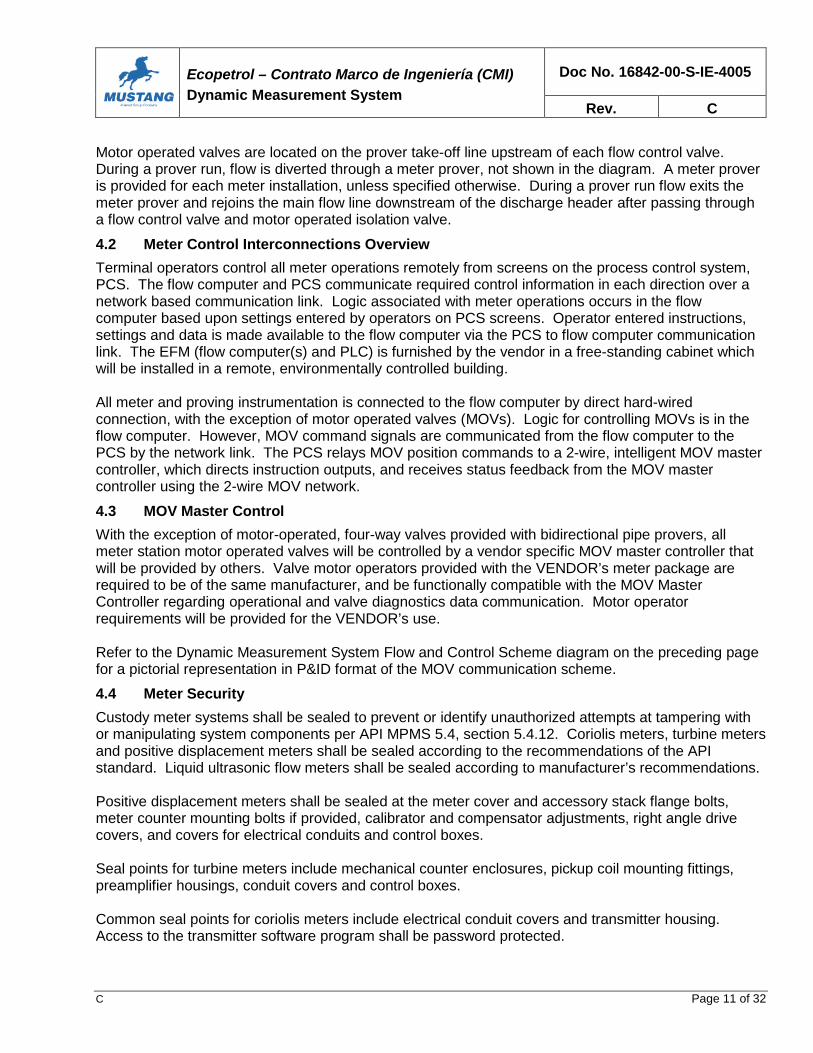
Ecopetrol – Contrato Marco de Ingeniería (CMI)
Dynamic Measurement System
Doc No. 16842-00-S-IE-4005
Rev. C
C Page 11 of 32
Motor operated valves are located on the prover take-off line upstream of each flow control valve.During a prover run, flow is diverted through a meter prover, not shown in the diagram. A meter proveris provided for each meter installation, unless specified otherwise. During a prover run flow exits themeter prover and rejoins the main flow line downstream of the discharge header after passing througha flow control valve and motor operated isolation valve.
4.2 Meter Control Interconnections Overview
Terminal operators control all meter operations remotely from screens on the process control system,PCS. The flow computer and PCS communicate required control information in each direction over anetwork based communication link. Logic associated with meter operations occurs in the flowcomputer based upon settings entered by operators on PCS screens. Operator entered instructions,settings and data is made available to the flow computer via the PCS to flow computer communicationlink. The EFM (flow computer(s) and PLC) is furnished by the vendor in a free-standing cabinet whichwill be installed in a remote, environmentally controlled building.
All meter and proving instrumentation is connected to the flow computer by direct hard-wiredconnection, with the exception of motor operated valves (MOVs). Logic for controlling MOVs is in theflow computer. However, MOV command signals are communicated from the flow computer to thePCS by the network link. The PCS relays MOV position commands to a 2-wire, intelligent MOV mastercontroller, which directs instruction outputs, and receives status feedback from the MOV mastercontroller using the 2-wire MOV network.
4.3 MOV Master Control
With the exception of motor-operated, four-way valves provided with bidirectional pipe provers, allmeter station motor operated valves will be controlled by a vendor specific MOV master controller thatwill be provided by others. Valve motor operators provided with the VENDOR’s meter package arerequired to be of the same manufacturer, and be functionally compatible with the MOV MasterController regarding operational and valve diagnostics data communication. Motor operatorrequirements will be provided for the VENDOR’s use.
Refer to the Dynamic Measurement System Flow and Control Scheme diagram on the preceding pagefor a pictorial representation in P&ID format of the MOV communication scheme.
4.4 Meter Security
Custody meter systems shall be sealed to prevent or identify unauthorized attempts at tampering withor manipulating system components per API MPMS 5.4, section 5.4.12. Coriolis meters, turbine metersand positive displacement meters shall be sealed according to the recommendations of the APIstandard. Liquid ultrasonic flow meters shall be sealed according to manufacturer’s recommendations.
Positive displacement meters shall be sealed at the meter cover and accessory stack flange bolts,meter counter mounting bolts if provided, calibrator and compensator adjustments, right angle drivecovers, and covers for electrical conduits and control boxes.
Seal points for turbine meters include mechanical counter enclosures, pickup coil mounting fittings,preamplifier housings, conduit covers and control boxes.
Common seal points for coriolis meters include electrical conduit covers and transmitter housing.Access to the transmitter software program shall be password protected.

Ecopetrol – Contrato Marco de Ingeniería (CMI)
Dynamic Measurement System
Doc No. 16842-00-S-IE-4005
Rev. C
C Page 12 of 32
5.0 METERING FUNCTIONAL DESCRIPTION
5.1 Meter Station Run Definition From the PCS Console
This functional description is written for positive displacement meters, but generally applies to othertypes of meters. When other meters are considered the flow ranging characteristic of the particulartype of meter should be used rather than the values contained here for positive displacement meters.
All operational parameters for batch and continuous meter installations are set at the PCS console byoperators and communicated to the EFM by Modbus TCP. The operator sets the order meters areplaced in service, and taken out-of-service, during the start-up and ramp down sequence. The operatordesignates out-of-service meters for exclusion from use during metering. The operator defines theproportional to flow automatic sampling rate for continuous meter stations and for batch meter stations.The flow computer accesses this information from the PCS at the beginning of meter operations.
For batch meters the operator identifies the batch product, batch size, number of meters to place inservice, and station flow rate from the PCS console. The flow computer (FC) accesses the productidentity and batch information from the PCS, and selects the appropriate meter factor per meter.
For continuous meters the PCS operator identifies the product, number of meters to place in service,and station flow rate. The flow computer (FC) accesses the product identity and run definition from thePCS, and selects the appropriate meter factor per meter.
5.2 Start-up
Prior to operating through the flow meters, piping upstream, downstream is filled and vented. With thevalve line-up complete along the transfer pathway, operators are ready to start flowing though themeters.
With one or more loading or transfer pumps in service on bypass, the PCS console operator instructsthe FC to start the batch. For batch meters, the electronic flow measurement system (EFM) runs thesampler fast loop for a predetermined period of time to flush out the sweep volume at the start of eachbatch prior to taking a sample. FC opens the discharge MOV on the lead meter run with the flowcontrol valve held closed. When the lead MOV open limit switch registers full open, the FC ramps openthe lead flow control valve at a controlled rate. The FC maintains backpressure override control on theflow control valve, set at an operator adjustable value.
As flow rate rises to a predetermined percent of meter range on the lead meter, the FC opens thedischarge MOV on the meter run 2. When the meter run 2 MOV reaches 100% open, as confirmed bythe position signal from the MOV controller, the FC ramps open the flow control valve, withbackpressure override control maintained.
The FC places succeeding meter runs in service until the designated flow rate across the meter stationis achieved.
5.3 In Service
During in-service operation, the FC balances flow through the meters to maintain operation at theoptimal point for metered accuracy and meter wear. Positive displacement meters will typically operatebetween 20% and a maximum 75% of rated capacity. Optimal operation for positive displacementmeters is approximately 75% of range.

Ecopetrol – Contrato Marco de Ingeniería (CMI)
Dynamic Measurement System
Doc No. 16842-00-S-IE-4005
Rev. C
C Page 13 of 32
In the event total flow through the meters decreases to the adjustable minimum rate, the FC removesthe lag meter from service by throttling closed the flow control valve and closing the discharge MOV. Ifthe flow rate increases back to the predefined flow rate threshold, the FC returns brings the next meterback into service.
During a batch the PCS console operator may remove a meter from service, or revise the status of ameter from out-of-service to available.
At any time the PCS operator may interrupt metering operation from the PCS. In this case the FCexecutes a meter shutdown by closing the control valves and discharge MOVs. After a batch isinterrupted the operator may change the meter order of operation, revise any meter status to out-of-service, and restart the run. After a run is restarted from the PCS, the FC initiates restart and resumesmetering, control and totalizing functions.
In the case of batch metered transfers, after a batch is interrupted, the operator may elect to terminatethe batch, in which case the PCS instructs the FC to conclude measurement and totalizing functions forthe batch.
5.4 Ramp Down
As the conclusion of a batch transfer approaches the flow computer initiates ramp down. The FC shutsdown all meter runs except the lead meter, and reduces flow to minimum through the remaining meterrun for the final moments before the end. As the batch concludes on minimum flow, the control valvefully closes and the discharge MOV is closed. The flow computer sends a batch complete notificationto the PCS.
5.5 Proving
The operator may initiate a meter prove from the PCS console. When the operator selects a meter forproving, the FC initiates the proving process for the designated meter. The EFM (FC and PLC)coordinates opening the prover discharge and inlet MOVs, balancing flow through the prover as theprover discharge flow control valve takes control from the meter run flow control valve, and closing themeter run discharge MOV. In similar fashion, when the proving cycle(s) are completed, the EFMcoordinates restoring the meter run to normal service, updating the meter factor, and returns the proverto isolated, standby duty.
It is the VENDOR’s responsibility to design a seamless exchange of control between the meter runvalves and the prover flow control and isolation valves. The flow control valve on the prover dischargemaintains the same operator adjustable backpressure override setting as the meter run control valve.
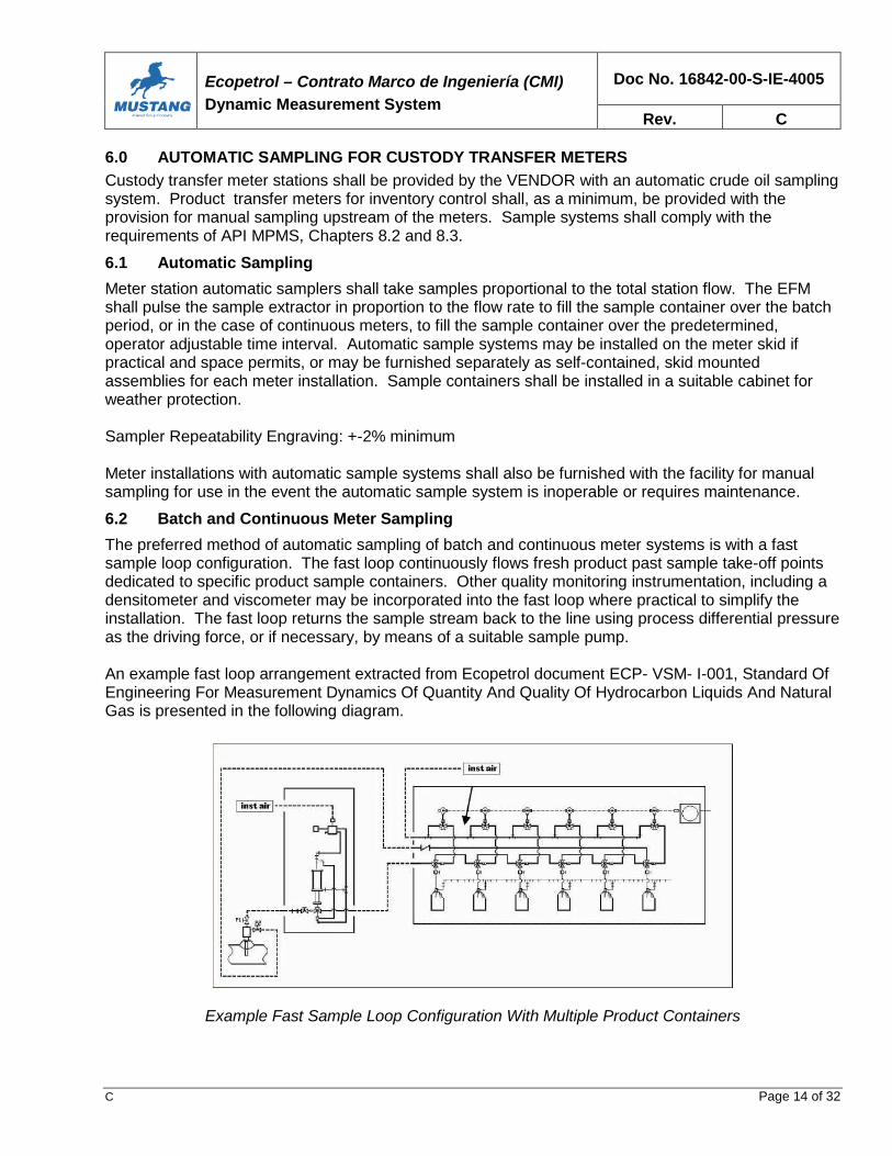
Ecopetrol – Contrato Marco de Ingeniería (CMI)
Dynamic Measurement System
Doc No. 16842-00-S-IE-4005
Rev. C
C Page 14 of 32
6.0 AUTOMATIC SAMPLING FOR CUSTODY TRANSFER METERS
Custody transfer meter stations shall be provided by the VENDOR with an automatic crude oil samplingsystem. Product transfer meters for inventory control shall, as a minimum, be provided with theprovision for manual sampling upstream of the meters. Sample systems shall comply with therequirements of API MPMS, Chapters 8.2 and 8.3.
6.1 Automatic Sampling
Meter station automatic samplers shall take samples proportional to the total station flow. The EFMshall pulse the sample extractor in proportion to the flow rate to fill the sample container over the batchperiod, or in the case of continuous meters, to fill the sample container over the predetermined,operator adjustable time interval. Automatic sample systems may be installed on the meter skid ifpractical and space permits, or may be furnished separately as self-contained, skid mountedassemblies for each meter installation. Sample containers shall be installed in a suitable cabinet forweather protection.
Sampler Repeatability Engraving: +-2% minimum
Meter installations with automatic sample systems shall also be furnished with the facility for manualsampling for use in the event the automatic sample system is inoperable or requires maintenance.
6.2 Batch and Continuous Meter Sampling
The preferred method of automatic sampling of batch and continuous meter systems is with a fastsample loop configuration. The fast loop continuously flows fresh product past sample take-off pointsdedicated to specific product sample containers. Other quality monitoring instrumentation, including adensitometer and viscometer may be incorporated into the fast loop where practical to simplify theinstallation. The fast loop returns the sample stream back to the line using process differential pressureas the driving force, or if necessary, by means of a suitable sample pump.
An example fast loop arrangement extracted from Ecopetrol document ECP- VSM- I-001, Standard OfEngineering For Measurement Dynamics Of Quantity And Quality Of Hydrocarbon Liquids And NaturalGas is presented in the following diagram.
Example Fast Sample Loop Configuration With Multiple Product Containers

Ecopetrol – Contrato Marco de Ingeniería (CMI)
Dynamic Measurement System
Doc No. 16842-00-S-IE-4005
Rev. C
C Page 15 of 32
6.3 Sample Point Piping Configuration and Stream Mixing
The sample probe shall be located in a zone where sufficient mixing results in adequate streamconditioning. The probe shall be installed at a position on the pipe that conforms in location andconfiguration to the requirements of API MPMS 8.2, section 10, figure 3, General Vertical Piping LoopConfiguration, and as extracted from Ecopetrol document ECP-VSM-I-001, section 7.2.4.1 shownbelow:
General Vertical Piping Loop Configuration
In cases where insufficient stream velocity exists for adequate mixing, a static mixer shall be usedaccording to API MPMS 8.2, Table 1, General Guidelines for Minimum Velocities Versus MixingElements.
6.4 Sample Probe
An insertion type sample extraction probe shall be provided by the meter station VENDOR. The probeinlet shall be oriented toward the oncoming flow. The probe tip shall be located at a point within themiddle 1/3 of the pipe. The VENDOR shall provide a vibration calculation to verify probe insertionlength construction acceptability. The probe shall be inserted through a piping class isolation valve andbe removable without taking the line out-of-service when provided with a suitable extraction tool.Extraction tool shall be furnished when specified.
Sample Probe Typical Designs
The mechanical design of the probe should be compatible with the operating conditions of the pipelineand the fluid being sampled. There are three basic designs as shown in the diagram, Sample ProbeTypical Designs, as extracted from Ecopetrol document ECP-VSM-I-001, section 7.2.4.2The preferred style of sample probe design is the ByScoop Sample Bypass Probe, manufactured byCameron Jiskoot, or approved alternate.

Ecopetrol – Contrato Marco de Ingeniería (CMI)
Dynamic Measurement System
Doc No. 16842-00-S-IE-4005
Rev. C
C Page 16 of 32
6.5 Sample Receivers
Separate, dedicated sample receivers shall be furnished for each product category. The samplecontainers shall be housed in a suitable cabinet for weather protection.
General sample receiver design shall include the following features: All receivers must permit the preparation of homogeneous sample mixtures The receiver base must be tilted continuously to permit complete emptying. There shall be no
dead sample points. The internal surface of receivers shall be designed to minimize corrosion and inhibit the
adhesion of liquid A means must be provided to monitor the fill percentage of the receiver A suitable means of pressure relief must be provided Vacuum breaker Pressure gauge Protection from adverse environmental conditions Receivers may require heat tracing in cases where high viscosity samples are taken. Evaluate
and provide if/where necessary. Receiver heating design, if used, must include protection fromover heat.
Multiple receivers are required for multiproduct meter stations. One dedicated receiver perproduct. Care shall be exercised in the design to prevent contamination between samples ofdifferent products.
Receivers must have a cover of adequate size to facilitate close inspection and cleaning The facility for providing a security seal must be provided. The sampling system must be capable of being completely drained, including the mixing pump
and all associated piping. The system must not include any dead zones/branches.

Ecopetrol – Contrato Marco de Ingeniería (CMI)
Dynamic Measurement System
Doc No. 16842-00-S-IE-4005
Rev. C
C Page 17 of 32
7.0 ELECTRONIC FLOW COMPUTER
Flow computer requirements presented in this section are based on Ecopetrol document no. ECP-VSM- I-001, section 8.1.
7.1 Flow Computer
The flow computer must meet the requirements of API MPMS Chapter 21.2.
The equipment must be able to develop application measurements of crude oil, and refined products,with calculation algorithms established by international standards applied in the field of measurement.
Flow meters having low resolution pulse can use pulse interpolation described in API MPMS 4.6"Proving Systems - Pulse Interpolation" to obtain the value of 0.01% pulse resolution.
The computer should monitor real-time process variables (e.g., temperature, pressure, flow meterpulse), command signals (such as early calibration batch cut, meter run flow balancing and closealignment, align a meter run with the prover, maintain measurement control using control valves, etc.),calculate and apply meter factors.
Online BS&W correction is not included for meters, unless specified otherwise. However, the flowcomputer must have the capability of calculating indicated volume, gross and net standard volumes.(For the computation of net standard volume, the flow computer must have the capability of batchreassessment for crude oil in the event a correction for BSW is required based on raw water andsediment data obtained by laboratory analysis. These data may be introduced into the system manuallyor by a system of data transmission (from the PCS). The flow computer must be capable of acceptingbase density (60 º F) obtained from laboratory analysis.
The flow computer must have the capability of printing a ticket from the meter, and test/prover reportswhich will provide alarm functions, historical reports, and access to archival data and monitoring ofbatches. The flow computer will keep in its memory a minimum of 8 tickets to provide for a recoveryoption. This memory capacity may be configurable to store up to 20 tickets for each class. Thecomputer will be able to perform all its functions online. The computer must have security levels toaccess settings.
7.2 Hardware Requirements
The flow computer will be mounted on a free standing Rittal or Hoffman cabinet.Audit trails must be provided that are self-implemented routines accessible through the keyboard or viaa PC program.
At least one communication port with Ethernet TCP/IP (Modbus/ TCP) for connection to the PCS.Four (4) serial communication ports: two ports are MODBUS communication protocol, the third is anRS-232C/RS- 485 interface capable of supporting multi-drop connection for direct connection to aprinter, and the fourth port is for configuration via PC.Analog outputs: 4-20 mA with a minimum resolution of 12 bits. The minimum resolution depends onsystem needs.Analog inputs: 4-20 mA signals with minimum resolution of 14 bits. The minimum amount will dependon the needs of the system.
Discrete inputs: Provide "high speed" input to permit connection of prover detector switches. Thequantity will depend on the needs of the station.

Ecopetrol – Contrato Marco de Ingeniería (CMI)
Dynamic Measurement System
Doc No. 16842-00-S-IE-4005
Rev. C
C Page 18 of 32
Discrete outputs: The amount will depend on the needs of the station.
Pulse Input: Positive displacement meter pulse inputs. The positive displacement meters for producttransfer are configured as a single monitoring station).
Check Density Meter: Online density monitoring provided for meters when specified.
RTD: Product transfer meters will receive temperature transmitter inputs. 4-wire, 100 ohm Pt RTDsmust be provided with direct connected temperature transmitters for input to flow computer.
Generally all types of inputs and outputs, require optical isolation.
HMI interface capability required to permit user configuration. Serial port for connection of laptop PC tobe provided.
Input voltage: 120 VAC. Must include protection against overvoltage / surge.
7.3 Software Requirements
The flow computer will have to allow its configuration through its own keyboard or via communications.In the case of remote configuration by communications the interface must be of GUI type (GraphicalUser Interface).
The computer must be configurable online.
The FC must support the configuration of conventional bidirectional provers and the doublechronometry, compact and master meters.
The FC must be able to print reports such as batch measurement tickets, calibration, configuration,daily, instantaneous and audits. All of these should be configurable. The method should be asillustrated in API MPMS 21.1.
The numbers of tickets, reports must be configured with six consecutive digits and a three-digit prefix,according to class.
The data base must have MODBUS communication tables (database with Modbus ID) with all systemvariables.
The FC should meet minimum requirements and conditions of "Level A" of the “system of fidelity andsecurity of transmission of pulses”, enumerated in API MPMS Chapter 5.5.4.5.
FC standard software shall incorporate features to improve and optimize the performance of flowmeters by linearization curves (with at least 5 test points) using the meter factor or K factor.
The tables must allow handling at least eight (8) different products for each meter.
The flow computer shall submit three (3) levels of security through the use of key management,maintenance and operation, to prevent unauthorized changes, whether by keyboard or communicationport. The computer must enable recording of historical record of access and actions in the setup. In thesame form must be possible to record alarm history.

Ecopetrol – Contrato Marco de Ingeniería (CMI)
Dynamic Measurement System
Doc No. 16842-00-S-IE-4005
Rev. C
C Page 19 of 32
The software must be capable of resettling a batch ticket to correct for density or BS&W.
The software must support retroactive application of a new Meter Factor on a batch in progress.
The software must have the ability to handle three types of files per meter: Batch ticket archives, dailyand calibration. Each with a capacity of at least the last 8 (eight) tickets in its class.
The software must support the use of different engineering units, the unit of measure selected for thecalculations must be the same for communications with the same level of resolution.
Acceptable Flow Computer Vendor: Emerson Daniel Model S600 (preferred)Omni

Ecopetrol – Contrato Marco de Ingeniería (CMI)
Dynamic Measurement System
Doc No. 16842-00-S-IE-4005
Rev. C
C Page 20 of 32
8.0 DISPLACEMENT PROVER
All custody and product transfer meter installations shall be furnished with a dedicated stationaryprover, or shall be piped to share a prover with another nearby meter installation if practical. Proversmay be unidirectional compact provers or bidirectional pipe provers.
Compact provers have the advantage over pipe provers in that a meter proving can be accomplished inless time than is required using a pipe prover. Meter installations for the Project could include severallarge meters which would require considerable time to prove all the meters using a pipe prover.
The application of compact provers to ultrasonic meters designed for high viscosity, low Reynoldsnumber measurement should be approached with caution. Use of a pipe prover avoids therepeatability problem and complexity associated with using a compact prover on an ultrasonic meter.
8.1 Compact Prover
Stationary compact prover may be considered where suitable for the meter service conditions. Thevendor is responsible for sizing the prover, taking into consideration the range of flow required forindividual meters, as well as the viscosity and specific gravity range of individual metered products forthe installation. The prover and installation shall comply with API MPMS 4.2, and may incorporatepulse interpolation per API MPMS 4.6.
Materials of construction for the prover and accessories shall be suitable for the coastal as well asinland environment within Colombia.
Small Volume Unidirectional Piston Displacement Prover – Minimum Technical Requirements
Manufacturer: Honeywell (Enraf Calibron) or COMPANY approved alternate.Model: To be determined.Service: Various crude oils and fuel oils. As identified on individual meter
installation data sheets.
Piping and Flange Material: Per the individual piping specification.Weatherproofing: NEMA 4Flow Range: Vendor to determine based on number of meters, total flow
and characteristic of meters.Wetted Parts: 316 SS, fluroelastomer, carbon steel unless specified otherwise.Cylinder and Connection Materials: Corrosion resistant hard steel.Flow Tube Material: 316 Stainless Steel, with hard chrome internal flow tube boreANSI B16.5 Flange Rating: Per project piping specification.Operational Pressure Rating: Pressure and Temperature Design Rating: Per individual meter
station data sheets.Inlet and Outlet Configuration: To be determined.
Motor Voltage Supply: 480 VAC/60 Hz, 3 phaseNEC Hazardous Area Class: Per individual meter station data sheets.Seal Materials: FluroelastomerRepeatability: Better than 0.02%, water draw.Rangeability: 1000-to-1Temperature Transmitter: Yes, per Appendix B. Emerson 3144, w/ 4-wire 100 ohm Pt RTD,
and Callender VanDusen configuration.

Ecopetrol – Contrato Marco de Ingeniería (CMI)
Dynamic Measurement System
Doc No. 16842-00-S-IE-4005
Rev. C
C Page 21 of 32
Pressure Transmitter: Yes, per Appendix B. Emerson 3051S1 ultra series.Bypass Valve: (Vendor to to advise)Poppet Valve: Hard, corrosion resistant stainless steelOptical Switches: Yes.Safety Valve: Yes.Vent and Drain Valves: Yes, per project piping and valve specification.Lubrication System: Required.Pressure Indication forLubrication System: 316SS wetted, phenolic Ashcroft 1279S series.Test Documentation: Certified test data for water draw test / repeatability; Functional
test of prover and components, and repeatability per API MPMSChapter 4; hydrostatic pressure test.
8.2 Bidirectional Pipe Prover
Requirements for bidirectional pipe provers will be added to this section later.

Ecopetrol – Contrato Marco de Ingeniería (CMI)
Dynamic Measurement System
Doc No. 16842-00-S-IE-4005
Rev. C
C Page 22 of 32
9.0 INSTALLATION REQUIREMENTS FOR METERING INSTRUMENTATION
Instrumentation and control system equipment associated with meters packages shall be installed inaccordance with Design Criteria 16842-00-S-IE-4001, Instrumentation For Packaged Equipment.
All electronic instrumentation furnished for outdoor installation with the transfer meters shall be certifiedby FM, CSA US, or other internationally recognized approval authority for use in NEC Class 1, GroupC, D, Division 2 hazardous area environments.

Ecopetrol – Contrato Marco de Ingeniería (CMI)
Dynamic Measurement System
Doc No. 16842-00-S-IE-4005
Rev. C
C Page 23 of 32
10.0 INSPECTION AND TESTING REQUIREMENTS
Meters installations shall be inspected and tested per the Inspection Matrix provided for each individualmeter station.
A factory acceptance test (FAT) is required in addition to other inspection, testing and verificationrequirements. The vendor is required to submit a proposed factory acceptance test procedure forreview and approval according to the Inspection Requirements document and matrix furnished as partof the commercial documentation.
The factory acceptance test will verify all electronic measurement system (EFM) functionality, includingthe flow computer, PLC (if provided), inputs and outputs, including soft inputs and outputs required forinterfacing between the flow computer and the terminal’s process control system, PCS. Also, the FATtest will verify proper operation of the MOV master control station, including I/O points communicatedbetween the PCS and the MOV master station. It is the vendor’s responsibility to provide appropriatetest equipment to simulate and verify all soft I/O data points communicated between the PCS and theflow computer and MOV master station. A hand held interface tool is available from Rotork to testelectric motor operator function.
The vendor shall have software available at the time of the FAT test to make any appropriate softwaremodifications that may be required.

Ecopetrol – Contrato Marco de Ingeniería (CMI)
Dynamic Measurement System
Doc No. 16842-00-S-IE-4005
Rev. C
C Page 24 of 32
11.0 VENDOR DATA REQUIREMENTS FOR METER INSTALLATIONS
Meter installation documentation shall be provided as required per vendor document specification andschedule number provided with the commercial documentation.

Ecopetrol – Contrato Marco de Ingeniería (CMI)
Dynamic Measurement System
Doc No. 16842-00-S-IE-4005
Rev. C
C Page 25 of 32
APPENDIX A – EXAMPLE PROCESS DESIGN DATA
Piping Pressure and TemperatureDesign Specification: ### psig at ### degrees F.
Allowable pressure drop across the meter installation, including proving, at normal flow rate: ### psigVendor shall provide hydraulic calculations to verify.
Product Category Combustoleo(Fuel Oil)
CastillaCrude
RubialesCrude
MezclaCrude
Cano LimonCrude
CusianaCrude
Flow BPD: Min ###,### ###,### ###,### ###,### ###,### ###,###Flow BPD: Nor ###,### ###,### ###,### ###,### ###,### ###,###Flow BPD: Max ###,### ###,### ###,### ###,### ###,### ###,###
Temp degF Min ### ### ### ### ### ###Temp degF Norm ### ### ### ### ### ###Temp degF Max ### ### ### ### ### ###
Pressure OperPSIG
### ### ### ### ### ###
Viscosity cSt ### ### ### ### ### ###Specific Gravity ### ### ### ### ### ###
API Gravity ### ### ### ### ### ###Vapor Pressure Less than ###
PSIALess than### PSIA
Less than ###PSIA
Less than ###PSIA
Less than ###PSIA
Less than ###PSIA

Ecopetrol – Contrato Marco de Ingeniería (CMI)
Dynamic Measurement System
Doc No. 16842-00-S-IE-4005
Rev. C
C Page 26 of 32
APPENDIX B – INSTRUMENT REQUIREMENTS FOR METER INSTALLATIONS
Instrumentation Description For Dynamic Measurement Meter Installations
Instrumentation furnished by the VENDOR for custody and product transfer meters shall conform torequirements provided in this section. The vendor shall confirm the correctness of all model numberspresented and modify as required according to the specific requirements of each application, subject topurchaser approval. The VENDOR shall verify sizing of headers, meter runs, valves, and determineoverall pressure drop during normal operation and proving.
Schematic - Typical Meter Installation Showing Compact Prover

Ecopetrol – Contrato Marco de Ingeniería (CMI)
Dynamic Measurement System
Doc No. 16842-00-S-IE-4005
Rev. C
C Page 27 of 32
Flow Meters:Manufacturer: FMC (A.O. Smith)Model: Smith Meter CT series
Double case, positive displacement meterxx”-yyy# Flanged inlet and outlet connection.Flange Facing: Per applicable piping specificationCarbon steel constructionTwo pickups/two outputs required1000 pulse per barrel output resolution minimumAPI MPMS Chapter 5.2 compliance requiredRange: Vendor to determine acceptable minimum and maximum ranges asappropriate per individual product physical properties, i.e., viscosity, gravity.
Design viscosity range for meters: 2 cSt – 300 cSt. Vendor shall confirmapplication suitability for meters over this viscosity range.
Flow Curves andMeter Factors: The manufacturer shall provide a flow curve for each meter showing linearity
and a flow tested meter factor appropriate to the specified flow products.
Flow Control Valves:
Acceptable Vendors: Emerson Fisher
Material of Construction:Body and Bonnet: WCC Carbon Steel minimum., to comply with piping specificationPacking: TFE/Graphite Enviroseal
Valve Type: High Performance ButterflyRising Stem GlobeCharacterized Ball (V-ball)
Trim: Hardened alloy steelStem: Hardened alloy steelLeakage Rating: Class V shutoffEnd Connections: xx”-yyy# Flanged, 125 to 250 RA flange smoothness
Flange Facing: Per applicable piping specification
Sizing Data: Refer to meter installation data sheet(s)Pressure Drop: xx psig max.Manufacturer/ Model: Emerson Fisher /: Spring-opposed diaphragmInstrument Air: 175 psig max., 120 psig normal, 80 psig min.I/P Positioner: Fisher DVC 6000 seriesInput Signal: 4-20 mAAir to Positioner: Regulate as required to xx psigAir to Diaphragm Act.: 3 to 15 / 6 to 30 psig (to be confirmed)Action: Air to openFail Position: Fail Closed on loss of air/loss of signalRegulator/Gauges: Yes
Vendor to verify valve sizing and selection for the application based on process data provided.

Ecopetrol – Contrato Marco de Ingeniería (CMI)
Dynamic Measurement System
Doc No. 16842-00-S-IE-4005
Rev. C
C Page 28 of 32
Motor Operated Valves:Acceptable Vendor: General Twin SealValve Type: Quarter-turn, trunnion, top entry, API 6D
Standard PortEnd Connections: Prover Take-offs & Prover Return: xx”-yyy# ASME, 125 – 250 RA
Meter Run Inlet & Discharge Block: xx”-yyy# ASME, 125 – 250 RAFlange Facing: Per applicable piping specification
Materialsof Construction: Body and top flange (bonnet): WCC Carbon Steel min., body material to
comply with piping specification.Plug/Ball: Corrosion resistant hard-faced stainless steelStem: Hard alloy stainless steelSeat: Corrosion resistant hard-faced stainless steel
Seating: Double Block and BleedLeakage: API 6DThermal Relief: Integral differential thermal relief routed to upstream throat, with integrally
mounted manual body bleed for verifying seal integrity. Diff. relief set at25 psi above upstream pressure. Vendor to confirm body draindescription.
Fire Safe: API 6FASeals: Fire Seals: Graphite; Slip Seals: TeflonAnti-static ground: RequiredLubrication Connection: Yes, required.
Actuator:Acceptable Vendors: Rotork, no alternates permittedActuator Type: Intelligent Electric Motor Actuator
Actuator shall be controlled from Pakscan 3 valve network controller.Full diagnostics, valve status, and position data to be communicated toPakscan via 2-wire network connection.
Form: Isolation Duty/Worm DriveMounting Orientation: TopDuty Cycles: 2 cycles/dayIngress Protection: IP 67Power: 480 VAC, 3-phaseOpen/Close Time: 16” size: 16 to 40 secondsIntegral Reversing Starter: Yes
Position Feedback: 0 to 100% position feedback via PakscanTorque Switches: Yes, internalFail Position: Fail in last positionControls: Integral pushbuttons and lights for: Open/Close/Stop
Lockable Local-Off-Remote Switch, Open-Close Switch: YesRemote Control Signal: 2-Wire MOV Control NetworkControl signal to be matched with Rotork Pakscan MOV Master ControlStation being provided for project by others.
Diagnostics: Actuator to communicate full diagnostics data to Intelligent Master ValveController.

Ecopetrol – Contrato Marco de Ingeniería (CMI)
Dynamic Measurement System
Doc No. 16842-00-S-IE-4005
Rev. C
C Page 29 of 32
Densitometer (Complete densitometer details to be provided later.)Manufacturer/Model No.: Micromotion (formerly Solartron)Description: TBDMaterials ofConstruction: 316L SS minimum wetted partsConnection Size: x” flangedProcess Media: Crude Oils/Fuel OilOperating and Design: TBDPressure /Temperature: TBDInstrument Range: TBDMeasurement Range: TBDAccuracy: +-0.001 gr/cm3Repeatability: 0.0005 gr/cm3 over the range 0.5 to 1.1 gr/cm3Installation: Inline flow through type, mounted in sample slipstreamSignal Output: Frequency output, connected to flow computer.Electronics Enclosure: NEMA 4X, Epoxy coated aluminum
ViscometerManufacturer/Model No.: MicromotionDescription: TBDMaterials ofConstruction: 316L SSConnection Size: 2” flangedProcess Media: Crude Oils/Fuel OilOperating and DesignPressure /Temperature: TBDMeasurement Range: TBDAccuracy: TBDInstallation: Insertion type, mounting in sample slipstream pipingSignal Output: 4-20 mAElectronics Enclosure: NEMA 4X, Epoxy coated aluminum
Electronic Flow Measurement Cabinet (Flow Computer Cabinet)Description: Free standing cabinet to be provided for installation of flow computer and
PLC (if provided) in remote COMPANY provided MCC building. Cabinetdesign configuration to include swing door(s) with viewing window.Internal configuration by vendor for combination flow computer interface,terminals provided for field terminations.
Terminations: Field cables to be landed on terminal blocks in cabinet.Phoenix Contact terminals.
Cable Entry: Top or bottom to be determined LATER.Locking Hardware: Cabinet to be sealable with locking hardware for swing door(s).Cabinet Ventilation: Fan ventilation to be provided.Access: Front only or front and back to be confirmed LATER.Height x Width Dim.: Dimensional limitation to be provided LATER.Color: Vendor standard color/finish.Acceptable Vendors: Hoffman, Rittal

Ecopetrol – Contrato Marco de Ingeniería (CMI)
Dynamic Measurement System
Doc No. 16842-00-S-IE-4005
Rev. C
C Page 30 of 32
Automatic SamplerSystem: Per section 6 of this document.
Pressure Transmitters:Manufacturer: Emerson RosemountModel No.: 3051S1 T G xx 3 A11 A 1J E5 M5 Q4 T1 (Vendor confirm model no.)
Vendor to verify range model and span0.025 % span accuracyProvide assembled with Rosemount 2-valve manifoldModel 306 R T 2 2 BA 2 1 SGStainless steel bolting
Emerson 3051S1 seriesUltra Performance 0.025% of span accuracyInline MountGauge PressurePressure Range as requiredHastelloy C-276 diaphragmAssemble to Rosemount 306 RT, 2-valve, traditional series manifold4-20 mA output with superimposed HART protocolPlant web housing with ½” NPT conduit connection, 316L SS materialFM explosion proof certificationPlant web LCD displayCalibration certificateTransient Protection terminal block
Differential Pressure Transmitter:Manufacturer: Emerson RosemountModel No.: 3051S1 CD 3A 3 A11 A 1J E5 M5 Q4 T1 (Vendor to confirm model no.)
0.025 % span accuracy, traditional flange style mounting.Provide assembled to Rosemount 3-valve manifoldModel 305 R T 3 2 B 1 1 B4 SGStainless steel bolting
Emerson 3051S1 seriesUltra Performance 0.025% of span accuracyDifferential PressureDifferential Range as requiredHastelloy C-276 diaphragmAssemble to Rosemount 305 RT, 3-valve, traditional series manifold4-20 mA output with superimposed HART protocolPlant web housing with ½” NPT conduit connection, 316L SS materialFM explosion proof certificationPlant web LCD displayCalibration certificateTransient Protection terminal block
Temperature Transmitter:Manufacturer: Emerson Rosemount

Ecopetrol – Contrato Marco de Ingeniería (CMI)
Dynamic Measurement System
Doc No. 16842-00-S-IE-4005
Rev. C
C Page 31 of 32
Model No.: 3144P D5 A 1 E5 M5 T1 C2 C4 Q4 XA (Vendor to confirm model no.)Linearization: Callender-Van Dusen, sensor matched to transmitter.RTD, Thermowell and Transmitter furnished preassembled by vendor,PTFE taped and fully wired.
Emerson 3144 Series Temperature TransmitterStainless Steel ½”-14 NPT Conduit Entry4-20 mA output with superimposed HART protocolSingle sensor inputFM Explosion Proof and Non incendive certificationLCD DisplayCalibration CertificateTransmitter sensor matching to specific RTD5-point calibrationCalibration certificateSensor assembled to transmitter
RTD and Thermowell:Manufacturer: Emerson RosemountModel: 0068N 21 C 30 Dxxx Fxx E5 V1 Q8 R07 XA (Vendor to confirm model no.)
Element: Callender-Van Dusen, element matched to transmitterCallender-van Dusen constants per range 0 degC – 100 degC4-wire, 100 ohm Pt, single element22 AWG, Teflon insulated, nickel coated, stranded copper wire.Spring-loaded element matched to well,3” Nipple-union-nipple extension¼” diameter element, 316L SS sheath materialFM Explosion Proof certification316L SS Thermowell, Min. 300 # FlangeThermowell rating and facing per pipe specThermowell, RTD and transmitter to be furnished as preassembled unit
Thermowell: 1-1/2” - xxx# Flange 316L SS flange connectionTapered construction¼” Nominal bore1/2” NPT element connectionThermowell insertion depth: (“U” dimension), Vendor to determine. Element topenetrate 1/3 diameter into the line.Wake frequency calculation required.Flange rating per piping specification. Minimum flange rating: 300# ASME.
Note: Temperature transmitter and direct mounted RTD and Thermowell prewiredand assembled by vendor.

Ecopetrol – Contrato Marco de Ingeniería (CMI)
Dynamic Measurement System
Doc No. 16842-00-S-IE-4005
Rev. C
C Page 32 of 32
Thermal Relief Valves:Provide upstream of meter and on compact prover upstream of chamber.Spring operated, carbon steel body, 300 series stainless steel trim.Set at design pressure rating.
Pressure Gauges:Ashcroft 1279S series Duragauge or approved equalBlow out back4-1/2” gauge face, black letters, white background316 SS lower ½” threaded connection316 SS bourdon tube300 series SS trim accessoriesSilicone liquid filled gauge316SS wetted parts
Temperature Gauges:Ashcroft 50EI60E series or approved equal1/2” threaded connection¼” diameter stem, 316 SS constructionSafety glass lens, 5” dialAdjustable, every angle type316 SS construction
Thermowell(s)for Temp. Gauges: 1-1/2” -x00# RF 316L SS flange connection
Tapered construction¼” Nominal bore1/2” NPT element connectionDegree Celsius scaleNormal temperature to be in approximate middle third of range.Thermowell insertion depth: (“U” dimension), Vendor to determine. Element topenetrate 1/3 diameter into the line.Wake frequency calculation required.Provide lagging extension as required to place gauge outside insulation ifrequired.Stem length to match bore depth.Flange rating per piping specification. Minimum flange rating: 300# ASME.
Test Thermowell(s):1-1/2” -xxx# flange 316L SS flange connectionTapered construction3/8” Nominal bore (suitable for mercury test thermometer)1/2” NPT element connectionThermowell insertion depth: (“U” dimension), Vendor to determine. Element topenetrate 1/3 diameter into the line.Wake frequency calculation required.Provide threaded and knurled brass plug attached by chain.Bore depth to correspond to standard length bimetal temperature gauge.Flange rating per piping specification. Minimum flange rating: 300# ASME.
Related Documents