McGhee Engineering, Inc. Central City, Kentucky Wastewater Treatment Plant Expansion ADDENDUM No. 6 September 19, 2018 This ADDENDUM to plans, specifications and bidding documents for the subject project modifies the referenced items to the extent described herein. Items not modified by this ADDENDUM remain unchanged and in full effect. Bidders are required to acknowledge receipt of this ADDENDUM on the Bid Form. Specifications 1. Instruction to Bidders Revise these sections to read as follows: A. 11.01 “The Contract, if awarded, will be on the basis of materials and equipment specified or described in the bidding document, or those “or equal” or substitute materials and equipment subsequently approved by Engineer as an “equal” or substitute unless written request for approval has been submitted by the Bidder and has been received by the Engineer 5 days prior to the date for receipt of Bids in the case of a proposed substitute and 5 days prior in the case of a proposed “or equal”. Each such request shall comply with the Paragraphs 7.04 and 7.05 of the General Conditions. The burden of proof of merit of the proposed item is upon the Bidder. Engineer’s decision of approval or disapproval of proposed item will be final. If Engineer approves any such proposed item, such approval will be set forth in an Addendum issued to all prospective Bidders. Bidders shall not rely upon approvals made in any other manner. Substitutes and “or equal” materials and equipment may be proposed by Contractor in accordance with Paragraphs 7.04 and 7.05 of the General Conditions after the Effective Date of the Contract. Each such request shall include the Manufacturers’ Certification Letter (Exhibit D) for compliance with AIS requirements and any subsequent statutes mandating domestic preference, if applicable.” B. 12.01 A list of subcontractors, suppliers, individuals, or entities shall be submitted five (5) days after the bid opening to the OWNER. If requested by Owner, such list shall be accompanied by an experience statement with pertinent information regarding similar projects and other evidence of qualification for each such Subcontractor, Supplier, or other individual or entity. If

Welcome message from author
This document is posted to help you gain knowledge. Please leave a comment to let me know what you think about it! Share it to your friends and learn new things together.
Transcript

McGhee Engineering, Inc.
Central City, Kentucky
Wastewater Treatment Plant Expansion
ADDENDUM No. 6 September 19, 2018
This ADDENDUM to plans, specifications and bidding documents for the subject project modifies the referenced items to the extent described herein. Items not modified by this ADDENDUM remain unchanged and in full effect. Bidders are required to acknowledge receipt of this ADDENDUM on the Bid Form.
Specifications
1. Instruction to Bidders Revise these sections to read as follows:
A. 11.01 “The Contract, if awarded, will be on the basis of materials and equipment specified or described in the bidding document, or those “or equal” or substitute materials and equipment subsequently approved by Engineer as an “equal” or substitute unless written request for approval has been submitted by the Bidder and has been received by the Engineer 5 days prior to the date for receipt of Bids in the case of a proposed substitute and 5 days prior in the case of a proposed “or equal”. Each such request shall comply with the Paragraphs 7.04 and 7.05 of the General Conditions. The burden of proof of merit of the proposed item is upon the Bidder. Engineer’s decision of approval or disapproval of proposed item will be final. If Engineer approves any such proposed item, such approval will be set forth in an Addendum issued to all prospective Bidders. Bidders shall not rely upon approvals made in any other manner. Substitutes and “or equal” materials and equipment may be proposed by Contractor in accordance with Paragraphs 7.04 and 7.05 of the General Conditions after the Effective Date of the Contract. Each such request shall include the Manufacturers’ Certification Letter (Exhibit D) for compliance with AIS requirements and any subsequent statutes mandating domestic preference, if applicable.”
B. 12.01 A list of subcontractors, suppliers, individuals, or entities shall be submitted five (5) days after the bid opening to the OWNER.
If requested by Owner, such list shall be accompanied by an experience statement with pertinent information regarding similar projects and other evidence of qualification for each such Subcontractor, Supplier, or other individual or entity. If

McGhee Engineering, Inc.
Owner or Engineer, after due investigation, has reasonable objection to any proposed Subcontractor, Supplier, individual, or entity, Owner may, before the Notice of Award is given, request apparent Successful Bidder to submit an acceptable substitute, in which case apparent Successful Bidder shall submit a substitute, Bidder’s Bid price will be increased (or decreased) by the difference in cost occasioned by such substitution, and Owner may consider such price adjustment in evaluating Bids and making the Contract award.
2. Bid Form.
Please replace the existing section of the bid form with the attached.
3. Davis Bacon Wage Rates
Please replace the existing wage rate determination sheet with the attached.
4. Buried Piping and Appurtenance - Section 02600
a. Section 02600 2.02 BURIED PIPING – Add the following paragraphs (E and
F) after paragraph D. “E. Buried Natural Gas Piping:
1. Manufacturers: Performance Pipe, a division of Chevron Phillips Chemical Company LP, JM Eagle, or equal.
2. Buried natural gas pipe tubing, fittings, and joints shall be PE 2708 (PE 2406) polyethylene, SDR 11 or less, ASTM D2513 and D3350 pipe and fittings. Provide butt weld fittings conforming to ASTM D3261 or socket type fittings conforming to ASTM D2683.
3. Polyethylene pipe tubing, fitting, and joint materials shall be compatible and by same manufacturer. Fabricated fittings shall not be used. Match fittings to service rating of pipe.
4. Provide an anodeless riser connection between buried plastic gas service piping and metallic riser in accordance with the local codes. Provide a metallic riser consisting of HDPE fused coating on steel pipe for connection to aboveground building distribution piping. Underground horizontal metallic portion of riser shall be at least 24 inches in length before connecting to the plastic service pipe. An approved transition fitting or adaptor meeting design pressure rating and plastic pipe manufacturers recommendations shall be used where the plastic joins the metallic riser. Provide Elster, George Fischer Central Plastics, or equal.
5. Gas Transition Fittings: Provide manufactured steel transition fittings approved for joining steel and polyethylene pipe, conforming to AGA XR0603 requirements for transition fittings. Transition fittings shall be manufactured by Continental, Elster, George Fischer Central Plastics, or equal.
6. Underground installation of piping shall conform with ASTM D2774.

McGhee Engineering, Inc.
7. Provide tracer wire as specified. F. Tracer Wire:
1. Install 10 gauge solid tracer wire with buried pipe where specified. Wire shall be continuous and terminate at valve boxes, manholes, or at test stations as specified below. Wire shall be taped to pipe at 5 foot intervals for all piping except piping carrying combustible material. For pipe carrying combustible material, the tracer wire shall be placed in the trench directly above the pipe, maintaining 6 inches separation between the tracer wire and the pipe. Any splices in copper wire shall be soldered and fitted with a Raco, or equal, insulated watertight boot.
2. Tracer wire test stations shall be SnakePit magnetized tracer boxes by Copperhead Industries, or equal. Tracer box shall be corrosion-resistant brass wire lugs and wax pad to cover wire connection. Cover shall be color-coded according to APWA standards for fluid conveyed. Provide SnakePit Lite Duty Box in unpaved areas and Roadway Box in paved areas. Provide Rhino Triview Marker Posts, or equal, at all test stations. Provide custom decals to identify fluid in piping. The tracer wire shall be accessible at a minimum of every 500 feet along the pipeline and at horizontal bends in piping. The tracer wire shall run into and up the sides of all manholes and be secured near the casting. Test stations shall be placed as required between manholes to comply with the minimum 500 foot tracer wire accessibility requirement.
3. CONTRACTOR shall perform continuity testing of all tracer wire in the presence of OWNER or ENGINEER.”
b. Section 02600 3.01 INSTALLATION – Add the following paragraphs (18 to
30) after paragraph 17.
18. Gas piping shall be installed in accordance with state, local, and utility codes and the National Fuel Gas Code, NFPA No. 54. All natural gas piping shall be tested in accordance with all state, local, and utility codes pertaining to natural gas service or service requirements. CONTRACTOR shall arrange for natural gas service and shall coordinate service size and location and shall furnish and install all shutoff valves and pressure reduction as required.
19. Gas lines shall not be installed under buildings, structures, or in crawl spaces. 20. A Schedule 40 steel sleeve shall be installed on all natural gas risers passing
through asphalt or concrete slabs. Allow at least 1 inch of radial clearance between sleeve and riser. Void shall be filled with pea gravel.
21. Natural gas piping shall be buried a minimum depth of 36 inches, unless noted otherwise.
22. Install an electrically conductive 10 gauge copper wire with yellow insulation with buried natural gas piping. The tracer wire shall be installed at a distance of 4 inches to 6 inches adjacent to the pipe. The wire and all of its connections shall be insulated to prevent corrosion.
23. Do not install natural gas piping in same trench with other utilities. Minimum horizontal clearance between gas pipe and parallel utility pipe shall be 2 feet.

McGhee Engineering, Inc.
Natural gas pipe shall not be installed through catch basins, vaults, manholes or similar underground structures.
24. Natural gas entrances into buildings shall be above grade. 25. Protection Against Shear and Bending Loads: In accordance with ASTM D2774,
natural gas connections shall be protected where an underground polyethylene branch or service pipe is joined to a branch fitting such as a service saddle, branch saddle, or tapping tee on a main pipe, and where pipes enter or exit casings or walls. The area surrounding the connection shall be embedded in properly placed, compacted backfill, preferably in combination with a protective sleeve or other mechanical structural support to protect the polyethylene pipe against shear and bending loads.
26. Butt, socket, and saddle fusion joints in polyethylene natural gas piping shall be made using procedures that have been qualified and approved by the Operator in accordance with Title 49, CFR, and Part 192.283.
27. In accordance with CFR. 49, part 192, Section 192.285, the Operator shall ensure that all persons making heat fusion joints have been qualified to make joints in accordance with the Operator’s Approved Qualified Fusion Procedures. The Operator shall maintain records of qualified personnel, and shall certify that qualification training was received not more than 12 months before commencing construction. CONTRACTOR shall ensure that all persons making heat fusion joints are qualified in accordance with this section.
28. Butt fusion of unlike wall thickness: Butt fusion shall be performed between pipe ends, or pipe ends and fitting outlets that have the same outside diameter and are not different in wall thickness by more than one Standard DR. Transitions between unlike wall thickness greater than one SDR shall be made with a transition nipple or by mechanical means or electrofusion.
29. Polyethylene natural gas pipe and fittings may be joined together or to other materials by transition fittings, fully restrained mechanical couplings, or electrofusion. These devices shall be designed for joining polyethylene to another material and shall be approved by ENGINEER for use in natural gas distribution system.
30. When mechanical OD compression couplings are used, polyethylene natural gas pipe shall be reinforced with a stiffener in the pipe bore. Stiffeners shall be properly sized for the diameter and wall thickness of polyethylene pipe being joined. For service pipe connections, the stiffener length shall match the pipe end penetration depth into the coupling.
c. Section 02600 3.02 FIELD QUALITY CONTROL – Add the following paragraph (H)
after paragraph G.
“H. Natural Gas Piping System Pressure Testing 1. Verify that the piping system being tested is fully connected to all components
and that all equipment is properly installed, wired, and ready for operation. If required for the additional pressure load under test, provide temporary restraints at expansion joints or isolate them during the test. Verify that hangers can withstand any additional weight load that may be imposed by the test.
2. All natural gas systems shall be inspected, tested, purged and placed into operation in accordance with NFPA 54 and as required by local code.
3. Conduct pressure test with air. Test time and pressure is indicated in the table below; additional time may be necessary to conduct an examination for leakage. Each test must be witnessed by Division 15 representative. If leaks are found,

McGhee Engineering, Inc.
repair the area with new materials and repeat the test; caulking will not be acceptable.
System Pressure Medium Duration
Natural Gas
3 psig <1.5 times operating pressure <50% minimum yield strength of pipe.
Air 1/2 hour per 500 cubic feet pipe volume not to exceed 24 hours.
4. Gradually increase the pressure to not more than one half of the test pressure;
then increase pressure in steps of approximately one-tenth of the test pressure until the required test pressure is reached. Examine all joints and connections with a soap bubble solution or equivalent method. The piping system exclusive of possible localized instances at pump or valve packing shall show no evidence of leaking. After testing is complete, slowly release the pressure in a safe manner.
5. All natural gas piping systems shall be carefully inspected, tested, purged and placed into operation by a Licensed Plumber. Tester shall submit pneumatic tests to ENGINEER.
6. All necessary piping, fittings, blind flanges, and apparatus for conducting tests shall be furnished by the CONTRACTOR and comply with the requirements of NFPA 54 and as required by local code.
7. All new rough-in distribution piping and affected portions of existing systems connected to, shall be subjected to a pneumatic test pressure utilizing clean, dry air and must be demonstrated to be absolutely tight when subjected to the pressures and time durations listed in table below. All equipment and components designed for operating pressures of less than the test pressure shall not be connected to the piping system during test.
8. Test pressure shall be measured with a manometer or with a pressure-measuring device designed and calibrated to read, record or indicate a pressure loss caused by leakage during the pressure test period.
9. Piping system shall withstand test pressure specified without showing any evidence of leakage or other defects. Any reduction of test pressures as indicated by pressure gauges shall be deemed to indicate a leak unless can be attributed to some other cause.
10. Leakage shall then be located by means of an approved gas detector, a noncorrosive leak detection fluid, or other approved leak detection method. Matches, candles, open flames or other methods that provide a source of ignition shall not be used.
11. When placing system into operation appliances and equipment shall not be placed into operation until piping system has been checked for leakage with above requirements.”
5. Metal Building System - Influent Pump Station - Section 13120 - 2.05.D - Page 13120-6
a. The bridge crane system and all accessories shall be rated for a Class I, Division 1 Groups C and D environment.
6. Container Handling System - Section 14550 - 1.03.C - Page 14550-1

McGhee Engineering, Inc.
a. Remove paragraph 1.03C. Container Handling System is not required to be suitable for operation in Class I, Division 1 Group D hazardous environments.
7. Container Handling System - Section 14550 - 2.06.C - Page 14550-4
a. Remove paragraph 2.06C in its entirety. 8. Container Handling System - Section 14550 - 2.06.G - Page 14550-4
a. The two travel limit switches shall be NEMA 4X. 9. Container Handling System - Section 14550 - 2.08.C - Page 14550-5
a. All controls are to be located in a NEMA 4X enclosure and are not required to be rated for Class I, Division 2 hazardous environments. All control devices, including but not limited to, pushbuttons, indicating lights, and selector switches shall be NEMA 4X.
10. Container Handling System - Section 14550 - 2.08.D - Page 14550-5
a. Warning horn and light shall be mounted to the container handling system control panel and shall be NEMA 4X.
11. General Electrical Requirements - Section 16010 - 3.06.B - Page 16010-7
a. Caulking sealant shall be as manufactured by General Electric, or equal. 12. Conduit - Section 16110 - 2.04.B - Page 16110-4
a. Couplings shall be as manufactured by Crouse Hinds EC Series, Appleton EX Series, or equal.
13. Conduit - Section 16110 - 2.05.D - Page 16110-4
a. Expansion Deflection Fittings shall be O-Z type “DX,” Crouse Hinds, type XD (PVC conduit only), Appleton, or equal.
14. Wiring Devices - Section 16141 - 2.01.A - Page 16141-2
a. A-C general use Industrial specification grade snap switch, 20 amperes, 277 volts shall be Cooper 222*, Leviton 122*, Pass and Seymour PS20AC*, or equal.
15. Wiring Devices - Section 16141 - 2.01.D - Page 16141-2

McGhee Engineering, Inc.
a. Manual motor switches or manual motor controllers for 120 V or 240 V motors
on circuits 20 amps or less shall be specification grade snap switch as specified above. Manual motor switches or manual motor controllers for 120 V or 240 V motors on circuits 30 amps or less shall be Cooper 303*, Leviton 303*, Pass and Seymour PS30AC*, or equal. Manual motor switches for three-phase motors 30 amps or less shall be as specified in Section 16440–Disconnect Switches.
16. Wiring Devices - Section 16141 - 2.02.A - Page 16141-2
a. Twenty ampere, 125-volt, NEMA 5-20R, Industrial specification grade, straight blade, 3-wire duplex grounded outlets shall be Cooper 5362, Leviton 5362, Pass and Seymour 5362, or equal. Provide ivory color.
17. Wiring Devices - Section 16141 - 2.02.C - Page 16141-2
a. GFCI Receptacle: GFCI receptacles shall be UL 943 listed, Pass and Seymour 2097, Cooper TRVGF20, or equal, receptacle with integral ground fault current interrupter. Provide ivory color.
18. Wiring Devices - Section 16141 - 2.02.E - Page 16141-2
a. Class I Receptacles: Crouse Hinds CPS-152,Appleton CPS, or equal. Provide two plugs (total) to match receptacle.
19. Standby Power System - Section 16230 - 2.01.A - Page 16230-2
a. The AC engine-generator set shall be as manufactured by Cummins Power Generation Model DQFAD, Kohler, Caterpillar, or equal.
20. Low-Voltage Distribution Switchboards (Group-Mounted) - Section 16429 -
2.06.D - Page 16429-5
a. Circuit breakers 250 amperes frame and below shall be Eaton, or equal, with thermal magnetic trip units and inverse time-current characteristics.
21. Low-Voltage Distribution Switchboards (Group-Mounted) - Section 16429 -
2.06.E.8 - Page 16429-5
a. Trip units shall be microprocessor-based RMS-sensing type Digitrip RMS 310+, or equal.
22. Disconnect Switches - Section 16440 - 2.01.A - Page 16440-1

McGhee Engineering, Inc.
a. Disconnect Switches shall be Square D Class 3110, Cutler Hammer Type DH, or equal.
23. Disconnect Switches - Section 16440 - 2.01.B - Page 16440-1
a. Manual Motor Switches: Square D Class 2510 Type K, Cutler Hammer B330, or equal.
24. Controls and Instrumentation - Section 16940 - 1.03.B - Page 16940-3
a. Installer shall be a firm with at least 5 years of successful installation experience on projects with SCADA System design and installation work similar to that required for the project.
25. Controls and Instrumentation - Section 16940 - 1.08.I - Page 16940-6
a. The Base Bid System Supplier shall be HTI, Inc., (270) 274-4632, Wunderlinch-Malec (952) 933-3222, Integrated Process Solutions, (608) 849-4375, or equal. See General Conditions and Supplementary Conditions regarding substitutions to the Base Bid system suppliers.
26. Controls and Instrumentation - Section 16940 - 1.10.A - Page 16940-9
a. New enclosures shall be a minimum of 24 inches wide, 20 inches deep, and 90
inches high and shall be as manufactured by Hoffman, Saginaw, or equal. 27. Section 8810 – Glass and Glazing
Revise section 2.06.D to read as follows: Products: Provide one of the following (or equal):
1. One-Part Non-Acid Curing Medium-Modulus Silicone Glazing Sealant: a. “Dow Corning 795”; Dow Corning Corp.
b. “Silpruf’; General Electric Corp.
c. “Gesil”; General Electric Corp.
d. “Spectrum 2”; Tremco, Inc.
2. Preformed Butyl-Polyisobutylene Glazing Tape with Spacer Rod: a. “Chem-Tape 60”; Bostik Construction Products Division.
b. “Shim-Seal”; Pecora Corp.
c. “PTI 303” Shim Tape; Protective Treatments, Inc.
d. “Pre-shimmed Tremco 440 Tape”; Tremco, Inc. 28. Section 09900 – Painting

McGhee Engineering, Inc.
Allow for “or equal” each of the following sections: 3.05.A.4, 3.05.B.3 through 3.05.B.5, and 3.05.B.7 through 3.05.B.12.
29. Section 11300 – Submersible Influent Wastewater Pumps
Revise section 2.1 to read as follows:
The manufacturer shall be represented by a distributor with at least one factory certified technician qualified to service the pumping equipment, a factory approved shop for maintenance and repair of the pumping equipment, and a stock of repair and service parts.
30. Section 11320 – Grit Removal System
Revise these sections to read as follows:
A. 1.04.D. MANUFACTURER shall be successful in the experience of manufacture, operation, and servicing of Grit Removal Systems of type, size, quality, performance, and reliability equal to that specified for a period of not less than five (5) years. The MANUFACTURER shall submit evidence of experience having supplied a minimum of ten (10) installations in North America of similar size to the proposed system. The MANUFACTURER shall submit evidence of experience in the State of Kentucky having supplied a minimum of three (3) installations of similarly sized grit concentrator equipment in Kentucky.
B. 1.04.E. In the absence of verifiable experience, the MANUFACTURER shall
be required to provide an extended warranty and subsequent Performance Bond for the same number of years that the MANUFACTURER was found lacking in experience from the specified five (5) year period. The performance bond shall commence with acceptance of the equipment and time described herein and beyond the standard warranty period.
C. 1.04.F. If equipment other than that shown on the Drawings is submitted to the Engineer for consideration as an equal, it shall be the responsibility of the CONTRACTOR requesting approval to submit with the request a revised design and layout of the mechanical equipment acceptable to the ENGINEER. Revised drawings shall show the proposed location of the alternate unit, and area required for withdrawal space of replacement or serviceable components. This drawing shall also show clearances of adjacent equipment and service area required by that equipment.
D. 1.04.G. Changes in architectural, structural, electrical, mechanical and plumbing requirements for the alternate shall be the responsibility of the Manufacturer requesting approval. This shall include the cost of redesign by affected designers. Any additional cost incurred by affected subcontractors shall be the responsibility of the CONTRACTOR and not the OWNER.

McGhee Engineering, Inc.
E. 1.05.A. The entire Grit Removal System shall be manufactured by Hydro
International, Hillsboro, OR., or equal.
31. Section 11320 – Grit Removal System
A. Remove Section 1.04.I. B. Remove Section 1.05.B. C. Remove Section 2.01.B.2
32. Section 11330 – Perforated Plate Influent Sewage Screen
Revise section 1.04.B. to read as follows: Manufacturer shall have a minimum of five (5) years of experience in designing, fabricating, and producing substantially similar equipment, and shall be able to show evidence of at least ten (10) installations in satisfactory operation for at least three years.
10. Section 11330 – Perforated Plate Influent Sewage Screen
Remove Section 2.01 11. Section 11331 – Influent Screenings Wash Press
Revise these sections to read as follows: A. 1.04.B. Manufacturers shall have a minimum five (5) years history of
engineering and fabricating screenings wash presses. Documentation of at least ten (10) installations having been installed for a minimum of five (5) years shall be provided.
B. 3.02.A. Lifting points shall be identified on all equipment. A crane of sufficient
capacity must be on site for unloading the equipment from the truck and placing in the channel for installation.
C. 3.04.A. The initial start-up of equipment will be performed by equipment
personnel and/or an authorized representative. The authorized representative will verify the proper operation and installation, and provide training to the equipment operators with start-up of the screen.
12. Section 11340 – Peracetic Acid Storage and Feed Equipment
Revise these sections to read as follows:

McGhee Engineering, Inc.
A. 1.01.B. Chemical Metering Pumps shall be positive displacement pumps of
either the electronic solenoid actuated diaphragm type. This specification addresses skid mounted chemical metering pump systems complete with the skid assembly containing chemical metering pumps, all necessary piping, valves, fittings, supports, electrical controls, and accessories as specified herein. The metering pump skid shall contain the following items:
1. Metering pumps with adjustable stroke length adjustment 2. Calibration column 3. Pulsation dampeners 4. Pressure gauges with diaphragm seals 5. Ball valves 6. Pressure relief valves 7. Backpressure valves 8. All piping, valves, gaskets, supports, hardware, wiring, and accessories
necessary for a fully functioning skid. B. 2.01.C.2 The enclosure shall allow for complete access to the front of the
system. The enclosure shall have two swing out doors and removable panels. The enclosure shall be constructed of white polypropylene. The enclosure shall provide adequate support for all pumps and piping. Fork lift truck cut outs be provided. Dimensions of the enclosure shall be no greater than 48”W x 36”D x 62”H.
C. 2.05
A. Basis of design is equipment from ProMinent Fluid Controls, Inc., or equal.
B. Acceptable Manufacturers: ProMinent Fluid Controls, Inc., Flowmotion Systems, or equal.
13. 11730 – Ultraviolet Disinfection Equipment
Revise this section to read as follows: 2.01.1. The physical layout of the system shown on the contract drawings
and the equipment specified herein are based upon the UV3000PlusTM System, as manufactured by Trojan Technologies, London, Ontario, Canada. The equipment provided shall be equal to Trojan.
14. 16141 – Wiring Devices
Allow for “or equal” in each of the following sections: 2.01.A, 2.01.D, 2.02.A, 2.02.C, and 2.02.E.

McGhee Engineering, Inc.
15. 16230 – Standyby Power System
Allow for “or equal” in each of the following sections: 2.01.A 16. 16429 – Low Voltage Distribution Switchboards
Allow for “or equal” in each of the following sections: 2.06.D and 2.06.E 17. 16440 – Disconnect Switches
Allow for “or equal” in each of the following sections: 2.01.A and 2.02.B 18. 16940 – Controls and Instrumentation
A. Allow for “or equal” in each of the following sections: 1.08.I.
B. Revise section 1.03.B. to read as follows: A firm with at least five (5) years of successful installation experience on projects with SCADA System design and installation work similar to that required for the project.
C. Revise section 1.09.A to read as follows: System Supplier shall be
responsible for development of a formal address listing associated with each PLC and shall provide ENGINEER with an organized spreadsheet of all addresses to be used for programming of the HMI (human machine interface) software specified herein. Point listing shall be provided in Microsoft Excel format, grouped individually for each PLC, and neatly organized into groups such as discrete I/O, analog I/O, setpoints, alarms, historical data, and dialer configuration. Points not used with the HMI software or for internal PLC logic shall be removed or hidden from the listing. Spreadsheet shall be sent to ENGINEER a minimum of 12 weeks prior to the factory acceptance testing specified below. Any revisions made to the original spreadsheet shall be clearly identified by highlighting, colored text, or notes within the documents. Electronic files shall be named with the date and revision number.
D. Revise section 1.10.A to read as follows: New enclosures shall be front access only, minimum No. 12 gauge steel, and hinged doors, rotating lockable handle, 3-point latch on each supervisory equipment compartment door (not screws or bolts), with top and bottom bolts actuated by one rotating handle on large doors. Provide door stop kit for all panel doors, data pockets for wiring diagrams, and minimum 18-inch, bolt-on, LED light and door switch. Panels over 48 inches wide shall have two lights. Painting shall include phosphate treatment, zinc chromate iron oxide primer, baked rust-inhibiting enamel, gray interior, and OWNER-selected exterior color. All doors and panels shall be gasketed. All louvers shall be filtered with forced-air cooling as necessary by the supplier for conditions where installed. New enclosures shall be a minimum of 24 inches wide, 20 inches deep, and 90 inches high

McGhee Engineering, Inc.
and shall be as manufactured by Hoffman or Saginaw, or equal. MCC structures are not acceptable. Where installed next to motor control centers, enclosure painting shall match that of the MCC.
19. Section 02276 Modular Retaining Walls Add Verti-Block to the list of acceptable manufacturers. 20. Sludge Disposal Allowance
For bidding purposes, assume a total volume not to exceed 500 cubic yards of grit/sludge in the existing oxidation ditch to be removed and disposed of. Assume that the material is suitable for non-hazardous landfill disposable. If the quantity exceeds the assumed amount, contractor will be reimburse on a time and materials basis for the additional quantity. Contractor shall be responsible for arranging any required testing associated with the material disposal. Such testing may be charged against the project testing allowance.
21. Trickling Filter Demolition
No record drawings have been located for the existing trickling filter to be demolished. For bidding purposes, assume the filter media bed to be eight (8) feet thick, and the bottom slab to be twelve (12) inches thick. Assume all concrete to be reinforced, and that the demolished material is suitable for disposal by on-site burial. If the actual dimensions exceed the assumed dimensions, or if the material requires special disposal, contractor will be reimburse on a time and materials basis for the additional effort. Contractor shall be responsible for arranging any required testing associated with the material disposal. Such testing may be charged against the project testing allowance.
Drawings 1. WWTP Yard Piping Plan
a. Drawing 05-C-04 – WWTP Yard Piping Plan - Add 4” drain pipe from RAS
Flow Meter Box to 10” drain pipe in Clarifier Splitter Box No.1. b. Drawing 05-C-04 – WWTP Yard Piping Plan - Change the location of new 2”
NPW pipe enter structure 80. 2” NPW pipe will enter structure 80 from the Northwest corner and connect to the existing 2” PW service pipe with location shown in drawing 80-HP-01.
2. Sludge Dewatering Structure Floor and Equipment Layout Plan

McGhee Engineering, Inc.
a. Drawing 80-ASM-01 - Replace Drawing 80-ASM-01 with Drawing 80-ASM-01R. Note that the water supply piping was extended to the water hose stations.
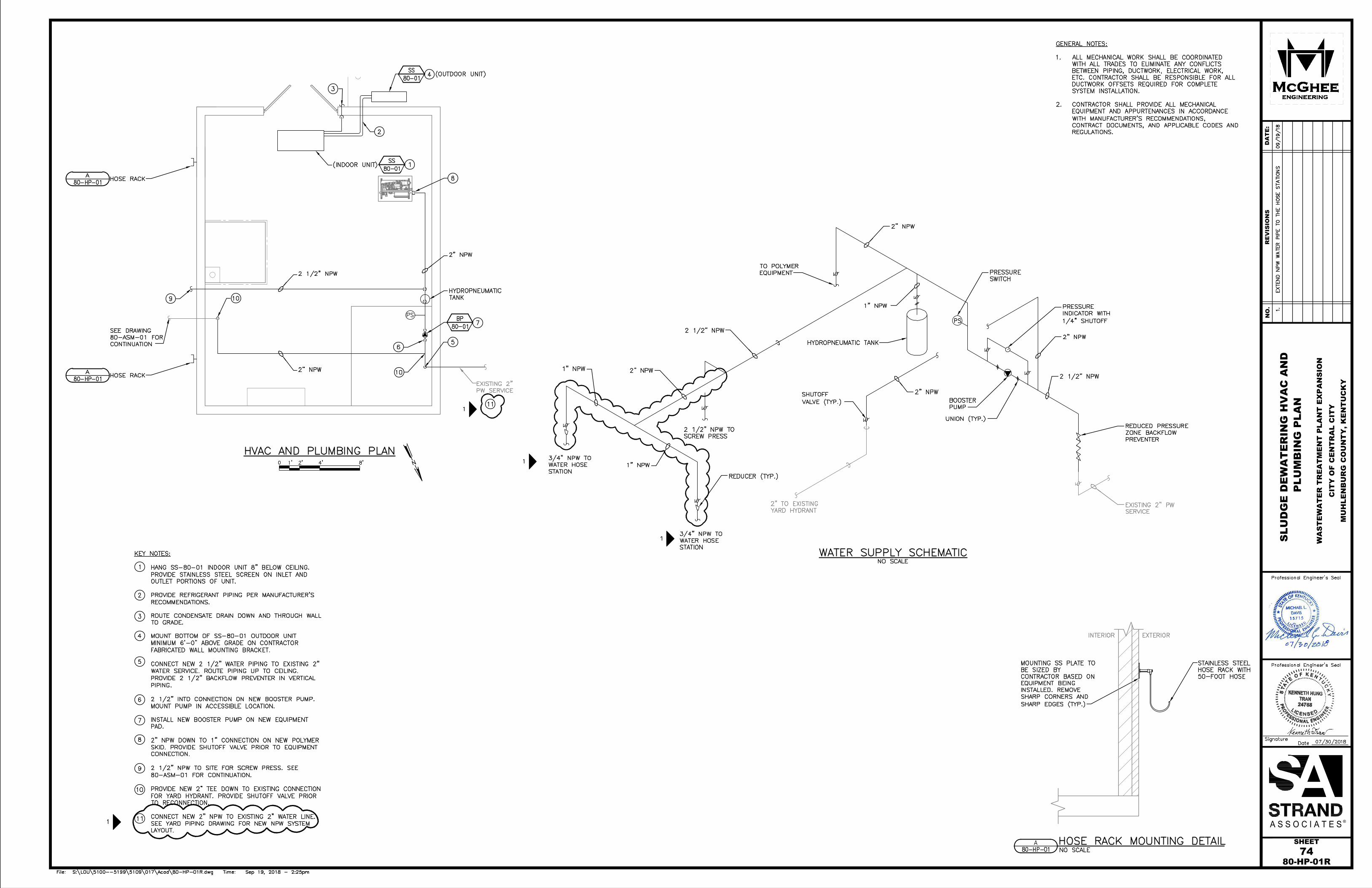
3. Sludge Dewatering HVAC and Plumbing Plan
a. Drawing 80-HP-01 - Replace Drawing 80-HP-01 with Drawing 80-HP-01R.
Note that the north arrow was rotated 180-degrees and the water supply schematic was extended to the water hose stations.
4. Degritter Structural Details a. Drawing 25-AMS-04 – Replace Drawing 25-ASM-04 with attached Drawing
25-ASM-04.
5. Peracetic Acid Feed System a. Drawing 70-ASM-03 – Replace Drawing 70-ASM-03 with attached Drawing
70-ASM-03.

EJCDC® C-410, Bid Form for Construction Contracts. Copyright © 2013 National Society of Professional Engineers, American Council of Engineering Companies,
and American Society of Civil Engineers. All rights reserved. Central City Water & Sewer Page 3 of 6 January 2017
ARTICLE 5 – BASIS OF BID
5.01 Bidder will compete the Work in accordance with the Contract Documents for the following lump sum price:
Lump Sum Bid Price In Figures $
In Words
BASE BID EQUIPMENT Specific equipment has been used in preparing the Contract Documents and thus establish the minimum quality that is acceptable. The Lump Sum Base Bid will be used to determine the low BIDDER and shall include use of acceptable equipment manufacturers. Any Bid that is not based on supplying equipment from acceptable manufacturers, or whereon the manufacturer of each type of equipment is not filled in may be declared non-responsive and receive no further consideration. The BIDDER hereby proposes to provide the following equipment for the stated base bid price:
Item Description of Equipment
A. Influent Screen & Wash Press
B. Influent Submersible Pumps
C. Degritting Equipment
D. Oxidation Ditch Equipment
E. Clarifier Equipment
F. UV Disinfection Equipment
G. PAA Feed Equipment
H. Sludge Dewatering Equipment
I. Sludge Pumps

EJCDC® C-410, Bid Form for Construction Contracts. Copyright © 2013 National Society of Professional Engineers, American Council of Engineering Companies,
and American Society of Civil Engineers. All rights reserved. Central City Water & Sewer Page 4 of 6 January 2017
J. Effluent Pumps
K. Generator/ATS
M. MCCs
N.
SCADA Integrator
5.02 The prices shall include all labor, materials, (all excavation is bid unclassified and will not constitute any
additional cost to OWNER if rock is encountered), overhead, profit, insurance, and other costs necessary to cover the finished work of the several kinds called for.
5.03 Bidder acknowledges that (1) the Lump Sum Bid Price includes an amount considered by Bidder to be adequate to cover Contractor’s overhead and profit for each separately identified item, and (2) estimated quantities are not guaranteed, and are solely for the purpose of comparison of Bids, and final payment for all unit price Bid items will be based on actual quantities, determined as provided in the Contract Documents.
5.04 SUPPLEMENTAL UNIT PRICES: The following Supplemental Unit Prices will apply in the event that
additions to or deductions from the work required in the Bid are ordered. A single price shall be bid for each item. OWNER reserves the right to accept or reject these prices by inclusion in or omission from the Contract Documents to be executed after the award of the Contract.
Item
Type of Work Unit Supplemental Unit Price (Words) (Numbers)
1. Earth Excavation CY . Dollars $ .
(Section 02-222)
Remove and Replace Unsuitable
2. Foundation Material for Structures, Roads and Basins
CY . Dollars $ .
(Section 02-222)
3.
Remove and Replace Unsuitable Foundation Material for Utility Trenches (Section 02-225)
CY
.
Dollars
$ .
4.
24-inch Influent Sewer Pipe Installation
LF
.
Dollars
$ .
5. 14-inch Effluent Force Main Installation LF . Dollars $ .
ARTICLE 6 – TIME OF COMPLETION 6.01 Bidder agrees that the Work will be substantially complete and will be completed and ready for final
payment in accordance with Paragraph 15.06 of the General Conditions on or before the dates or within the number of calendar days indicated in the Agreement.


McGhee Engineering, Inc.
END OF ADDENDUM NO. 6 TEXT This addendum consists of 24 pages of text and 4 plan sheets for a total of 28
pages.

SHEET
NO
.R
EV
ISIO
NS
DA
TE
:
A S S O C I A T E S
®
McGhee
Guthrie, KY 42234
202 Ewing Street
(270) 483-9985
Engineering
DE
GR
ITT
ER
BA
SIN
- S
TR
UC
TU
RA
L D
ET
AIL
S 1
WA
ST
EW
AT
ER
TR
EA
TM
EN
T P
LAN
T U
PG
RA
DE
S
CIT
Y O
F C
EN
TR
AL
CIT
Y
MU
HLE
NB
ER
G C
OU
NT
Y, K
EN
TU
CK
Y
April 17, 2017
McGhee
14440
L
I
C
ENS
E
D
P
R
O
F
E
S
S
I
O
NA L
E
N
G
I
N
E
E
R
Michael W.
S
T
A
T
E
O
F K
E
N
T
U
C
K
Y
25-ASM-0429
DEGRITTER BASIN STRUCTURAL SECTION A25-ASM-040 0.5' 1' 1.5' 2' 3' 4'
1'-0" 1'-6" 6'-0" 6'-0" 1'-6" 1'-0"
17'-0"
1'-6"
7'-0"
1'-51 2"
2'-41 2"
1'-0"
8'-2"
21'-6
"
7'-0"
7'-0"
6'-0"
1'-6"
7'-0"
6'-0"
1'-0"
6'-0"
7'-0"
7'-0"
6'-0"
1'-3"
1'-0" 3'-1" 1'-314" 12'-0" 1'-0"
18'-414"
8'-81 2"
3'-11 2"
1'-0" 2'-9" 1'-3" 12'-0" 1'-0"
18'-0"
1'-0" 1'-6" 6'-0" 6'-0" 1'-6" 1'-0"
17'-0"
DEGRITTER BASIN STRUCTURAL SECTION B25-ASM-040 0.5' 1' 1.5' 2' 3' 4'
1'-3" 1'-3"
TOP OF WALL ELEV 426.00
#5@12" VERTICAL (TYP)
#6@9" HORIZONTAL (TYP)LOWER SECTION
SEE MECHANICAL DRAWINGS FORPIPE PENETRATION SIZE & LOCATION
PRESSURE RELIEF VALVE
E25-ASM-05
KEYED CONSTRUCTIONJOINT WITH WATERSTOP (TYP)
CLAS
S "B
" SPL
ICE
(TYP
)
TOP OF WALL ELEV 426.00
DEGRITTER HATCH DETAIL C25-ASM-04NO SCALE
BASINWALL
34" SS EXPANCHOR
24"x24" ALUMINUMHATCH
W8 ALUMINUM GRATINGSUPPORT BEAM C4x2x1.80
ALUMINUMCHANNEL
ALUMINUM ANGLEFOR GRATING SUPPORT
L3x3x 316 HATCH
SUPPORT
34" SS BOLTS & L3x3x 3
16 CLIPANGLES FOR SHEARCONNECTIONS (TYP)
ALUMINUMGRATING
#5@12" VERTICAL (TYP)
#6@12" HORIZONTAL (TYP)MIDDLE SECTION
#5@12" VERTICAL (TYP)
#5@12" HORIZONTAL (TYP)UPPER SECTION
#5@12" EW, T&B
#5@12" EW, T&B
#6@9" EW, T&B
AutoCAD SHX Text
06-01-17
AutoCAD SHX Text
REVISED REINFORCING - AD#6
AutoCAD SHX Text
FOR FUNDING AGENCY REVIEW
AutoCAD SHX Text
0
AutoCAD SHX Text
09-19-18
AutoCAD SHX Text
1

SHEET
NO
.R
EV
ISIO
NS
DA
TE
:
A S S O C I A T E S
®
McGhee
Guthrie, KY 42234
202 Ewing Street
(270) 483-9985
Engineering
PE
RA
CE
TIC
AC
ID F
EE
D S
YS
TE
M -
PLA
N, S
EC
TIO
N &
DE
TA
ILS
WA
ST
EW
AT
ER
TR
EA
TM
EN
T P
LAN
T U
PG
RA
DE
S
CIT
Y O
F C
EN
TR
AL
CIT
Y
MU
HLE
NB
ER
G C
OU
NT
Y, K
EN
TU
CK
Y
April 17, 2017
McGhee
14440
L
I
C
ENS
E
D
P
R
O
F
E
S
S
I
O
NA L
E
N
G
I
N
E
E
R
Michael W.
S
T
A
T
E
O
F K
E
N
T
U
C
K
Y
6"16
'-0"
6"
3'-0" 9'-0"
6"
3'-0" 7'-0"
6'-0"
2'-6"
3'-0"
FROM PROPOSED CLARIFIER
TO UV SYSTEM
UV B
YPAS
SFR
OM E
XIST
ING
CLAR
IFIE
RS
36"x36" HATCH
EXISTING 24" DIPPAA TOTES
EYE WASH & SAFETY SHOWER(INSULATED & HEAT TRACED)
2" DRAIN
SLOP
E TO
DRA
IN
SLOPE TO DRAIN
CONCRETEVAULTPAA FEED
PUMP CABINET
CONCRETE CONTAINMENT AREA
PAA TOTES(330 GAL)
VALVE
PUMPSUCTION
HOSE
EYE WASH &SAFETY SHOWER
PAA FEEDCABINET
ALUMINUM HATCH
CONCRETE CONTAINMENTAREA WITH #3@12" E.W.
EXISTING 24" COMBINEDCLARIFIER EFFLUENT
12" TAP & ISOLATION
VALVE ON 24" DIP
PAA FEEDTUBING
CONCRETEVAULT
PAA SUCTIONHOSE
8"3'-
8"*
6"6"
SECTION C70-ASM-03
PLAN A70-ASM-03
70-ASM-0359
B70-ASM-04
0 1' 2' 3' 4' 6' 8'
0 1' 2' 3' 4' 6' 8'
* FIELD VERIFY BEFORECONSTRUCTING VAULT
12"
4" SIDEWALKWITH WWF
6" ELEV. 407.00
No. 57 AGR
6"2"
3'-8"
6"
6" 2'-6" 3'-0" 6" 6"
7'-0"
2"
8"
BLOCK OUTAROUNDEXIST PIPE
#4@12" E.W.
6"
BLOCK WALL SECTION IN PLACEAND POUR FOOTINGS IN PLACE
FILL WITH No. 57TO TOP OF FOOTING
LEAVE TAPEXPOSED
EXISTING 24" DIP
8"#4@18"2-#4
PAA FEEDPENETRATION
RAM-NEKSEALANT
#4@8" E.W.-T.&B.
36"x36" ALUMHATCH
PRECAST TOPAND WALLS
ELEV. 407.00
EXISTING 24" DIP - CONFIRMDEPTH AND SLOPE BEFORE
FABRICATING VAULT
WALL SECTION FOOTINGS(2 SIDES ONLY)
GROUT AFTERINSTALLATION
ALUMINUMHATCH
VAULT SECTION B70-ASM-030 0.5' 1' 1.5' 2' 3' 4'
VAULT SECTION D70-ASM-030 0.5' 1' 1.5' 2' 3' 4'
C70-ASM-04
D70
-ASM
-04
AutoCAD SHX Text
FOR KDOW REVIEW
AutoCAD SHX Text
04-17-17
AutoCAD SHX Text
REVISED DIMENSIONS - AD#6
AutoCAD SHX Text
0
AutoCAD SHX Text
1
AutoCAD SHX Text
04-17-17

SL
UD
GE
D
EW
AT
ER
IN
G S
TR
UC
TU
RE
FL
OO
R A
ND
E
QU
IP
ME
NT
L
AY
OU
T P
LA
NS
71
80-ASM-01R
A S S O C I A T E S
®
MU
HL
EN
BU
RG
C
OU
NT
Y, K
EN
TU
CK
Y
CIT
Y O
F C
EN
TR
AL
C
IT
Y
WA
ST
EW
AT
ER
T
RE
AT
ME
NT
P
LA
NT
E
XP
AN
SIO
N
SHEET
NO
.R
EV
IS
IO
NS
DA
TE
:
July 30, 2018
SL
UD
GE
D
EW
AT
ER
IN
G H
VA
C A
ND
PL
UM
BIN
G P
LA
N
74
80-HP-01R
A S S O C I A T E S
®
MU
HL
EN
BU
RG
C
OU
NT
Y, K
EN
TU
CK
Y
CIT
Y O
F C
EN
TR
AL
C
IT
Y
WA
ST
EW
AT
ER
T
RE
AT
ME
NT
P
LA
NT
E
XP
AN
SIO
N
SHEET
NO
.R
EV
IS
IO
NS
DA
TE
:
Related Documents