Addendum Air Quality Technical Report for the Final Environmental Impact Statement for the Mandan, Hidatsa, and Arikara Nation’s Proposed Clean Fuels Refinery Project March 9, 2011

Welcome message from author
This document is posted to help you gain knowledge. Please leave a comment to let me know what you think about it! Share it to your friends and learn new things together.
Transcript

Addendum
Air Quality Technical Report
for the Final Environmental Impact Statement
for the Mandan, Hidatsa, and Arikara Nation’s
Proposed Clean Fuels Refinery Project
March 9, 2011
dallen
Text Box
See EPA's May 9, 2011 letter regarding the applicability of the Clean Air Act requirements to the proposed MHA Nation Refinery. EPA did not concur with this report's conclusion that the proposed refinery would have potential emissions less than the Prevention of Significant Deterioration (PSD) permitting threshold. The preliminary design information and estimated air emission used in the EIS process are estimates of anticipated air emission. Whereas the determination of “potential to emit” for PSD permit applicability are a summation of the maximum air emissions that could be emitted from each specified refinery unit or air pollution unit.

Proposed Clean Fuels Refinery ii Air Quality Report Addendum
Table of Contents
Table of Contents ....................................................................................................................... ii
List of Tables ............................................................................................................................. ii
List of Appendices ..................................................................................................................... ii
Chapter 1 - Introduction .......................................................................................................... 1-1
Chapter 2 - MHA Refinery PTE Calculations .......................................................................... 2-1
Heater Normal Operation Calculations ................................................................................ 2-1
Boiler Normal Operation Calculations ................................................................................. 2-2
Heater and Boiler Startup, Shutdown, and Malfunction Calculations ................................... 2-2
Sulfur Recovery Unit Calculations ....................................................................................... 2-3
Flare Calculations ................................................................................................................ 2-3
Reformer Catalyst Regeneration .......................................................................................... 2-4
Fugitive VOC Calculations .................................................................................................. 2-5
Vehicle Traffic Fugitive PM10 Calculations ......................................................................... 2-5
List of Tables
Table 1 MHA Refinery Sources Included in the PTE Calculations ......................................... 1-1
Table 2 Revised Estimated Annual Emissions for the MHA Refinery .................................... 1-2
Table 3 SRU Emission Estimates ........................................................................................... 2-3
List of Appendices
Appendix A - Vendor Documentation
Appendix B - Emission Calculations

Chapter 1 - Introduction
This document has been prepared as an addendum to the December 2007 Air Quality Technical
Report for the Final Environmental Impact Statement for the Mandan, Hidatsa, and Arikara
Nation’s Proposed Clean Fuels Refinery Project (MHA Refinery). The final analyses and
assumptions included in this document are a result of a meeting with EPA Air Quality Technical
Staff and Tribal Representatives held on March 8, 2011.
This addendum addresses the Potential To Emit (PTE) calculations for oxides of nitrogen (NOx),
carbon monoxide (CO), sulfur dioxide (SO2), non-methane-ethane volatile organic compounds
(VOC), and particulate matter (PM) for the sources at the MHA Refinery shown on Table 1.
Table 1 MHA Refinery Sources Included in the PTE Calculations
Source ID Source 00001 Atmospheric Crude Heater
00002 Reformer Heater 1
00003 Reformer Heater 2
00004 Reformer Heater 3
00005 Reformer Heater 4
00006 Reformer Heater 5
00007 Hydrocracker 1
00008 Hydrocracker 2
00009 Hydrocracker 3
00010 Hydrocracker 4
00011 Olefin
00012 Hydrogen
00013 Boiler 1
00014 Boiler 2
00015 Boiler 3
00016 Flare
00017a Sulfur Recovery Tail Gas (main)
00017b Sulfur Recovery Tail Gas (backup)
00018 Vacuum Crude Heater
00019 Decant Oil Tank Heater 1
00020 Decant Oil Tank Heater 2
The Vacuum Crude Heater and two Decant Oil Tank Heaters have been added to this analysis
since the December 2007 Air Quality Technical Report. In addition, fugitive emissions of VOC
from the Vacuum Unit process and the two Decant Oil Tanks have been included in this analysis.
A backup Amine, Sulfur Recovery Unit (SRU), and Tail Gas system has also been added to the
MHA Refinery Design to limit SRU downtime and SO2 emissions from the flare. This backup
system will only operate when the main SRU system is not operating.

Chapter 1 - Introduction
Proposed Clean Fuels Refinery 1-2 Air Quality Report Addendum
Table 2 summarizes the revised estimated annual emissions of NOx, CO, SO2, VOC, and PM for
the MHA Nation’s proposed clean fuels refinery.
Emissions of NOx, CO, and SO2 from the emergency generator and fire pump engine have not
been updated. Therefore the previous estimates for these sources included in the December 2007
Air Quality Technical Report have been included in these totals.
Table 2 Revised Estimated Potential Annual Emissions for the MHA Refinery
Pollutant Annual Project Emission Rate (ton/yr)
NOx 55.8
CO 83.2
SO2 80.5
VOC 86.2
PM 38.8

Chapter 2 - MHA Refinery PTE Calculations
Local Williston Basin crude with a preference for MHA wells will be used as the feedstock for
the MHA Refinery. This crude is currently transported by truck to refineries in North Dakota
and Oklahoma. Processing this crude locally will result in a net reduction in truck traffic and
associated impacts.
Emission factors and assumptions for the revised calculations are presented below.
Documentation for vendor data is provided in Appendix A. Additional data and calculations are
provided in Appendix B.
Heater Normal Operation Calculations
Heater NOx emission estimates and fuel sulfur concentrations (to estimate SO2 emissions) are
based on maximum allowable concentrations under the federal regulation 40 CFR Part 60
Subpart Ja (Standards of Performance for Petroleum Refineries for Which Construction,
Reconstruction, or Modification Commenced After May 14, 2007). Heater CO emissions are
based on information provided by John Zink.
General assumptions:
� Boilers operate at 100% load and continuous operation except for startup, shutdown, and
malfunction events.
� 10 percent contingency added to normal emission rate estimates.
The normal heater emission estimates are based on the following concentrations:
� NOx emissions = 40 parts per million (ppm) corrected to 0 percent oxygen (O2).
� CO emissions = 50 ppm corrected to 3 percent O2.
� SO2 emissions based on fuel sulfur (as hydrogen sulfide (H2S)) concentration of 60 ppm
(annual average).
� VOC emissions = 5.5 pounds per million standard cubic feet (lb/MMscf) (USEPA
uncontrolled emission factor from AP-42 Table 1.4-2).
� PM emissions = 7.6 lb/MMscf (USEPA uncontrolled emission factor from AP-42 Table
1.4-2).
John Zink has also provided an estimate of 20 ppm corrected to 3 percent O2 for NOx emissions.
Therefore the NOx emission concentration used in the calculations is approximately twice the
anticipated concentration. The John Zink NOx emission concentration is based on the following
assumptions:
� Ultra LoNox burners,
� No air preheat (APH), and
� Natural gas and fuel gas combust at similar temperatures.

Chapter 2 - MHA Refinery PTE Calculations
Proposed Clean Fuels Refinery 2-2 Air Quality Report Addendum
The CO emission concentration is based on the following assumption:
� Natural gas and fuel gas burn at similar temperatures.
Boiler Normal Operation Calculations
Boiler NOx and CO emissions are based on information published by Webster Engineering and
Blesi Evans, a Webster vendor, in Minneapolis, Minnesota. Documentation for these data is
provided in Appendix A.
General assumptions:
� Assume 100% load and continuous operation except for startup, shutdown, and
malfunction events.
� NOx and CO data assumed to be based on 3 percent excess oxygen.
� 10 percent contingency added to normal emission rate estimates.
The normal boiler emission estimates are based on the following concentrations:
� NOx emissions = 30 ppm (Webster Engineering burners can achieve 9 ppm).
� CO emissions = 50 ppm (Webster Engineering and Manufacturing flyer and Blesi
Evans).
� SO2 emissions based on fuel sulfur concentration of 60 ppm.
� VOC emissions = 5.5 lb/MMscf (USEPA uncontrolled emission factor from AP-42
Table 1.4-2).
� PM emissions = 7.6 lb/MMscf (USEPA uncontrolled emission factor from AP-42 Table
1.4-2).
Heater and Boiler Startup, Shutdown, and Malfunction Calculations
General assumptions:
� 500 hours per year of startup, shutdown, or malfunction (SSM) events for each heater and
boiler.
� This estimated startup emission rates represent 1-hour averages.
The industry standard is to run the refinery for five years, with the exception of mandated
inspection intervals. The mandated inspections may shut down equipment for one or two days
each year. Once every five years, the refinery will shutdown for approximately 20 days for
maintenance.
As stated above, the heaters and boilers are assumed to operate continuously. For the startup and
shutdown emission calculations, emissions were increased to startup and shutdown emissions
levels, but no downtime emissions (zero emissions) were included in the calculations.

Chapter 2 - MHA Refinery PTE Calculations
Proposed Clean Fuels Refinery 2-3 Air Quality Report Addendum
For NOx, the USEPA uncontrolled emission factor for natural gas boilers less than 100 million
BTU per hour (MMBTU/hour) in size (AP-42 Table 1.4-1) was used to represent
startup/shutdown emissions.
� NOx emissions = 100 pounds per million standard cubic feet (lb/MMscf)
� CO emissions = 200 ppm. Maximum startup concentration provided by John Zink.
� SO2 emissions based on fuel sulfur (as H2S) concentration of 162 ppm (allowable 3-hour
average under 40 CFR Part 60 Subpart Ja).
� VOC and PM based on the same AP-42 emission factors used for normal operation
calculations.
Sulfur Recovery Unit Calculations
To calculate the Sulfur Recovery Unit (SRU) emissions, the project tail gas data from Table 14
in the Air Quality Technical Report were used to calculate emissions presented on Table 3.
These estimated tail gas emissions were based on Canadian synthetic crude processing, thus
should reflect conservative sulfur concentrations relative to Williston Basin crude processing.
Table 3 SRU Emission Estimates
Species
SRU Tail Gas
Exhaust
Flow
(lb-mol/hr)
Molecular Weight
(lb/lb-mol)
Emission Rate
(lb/hr)
CO 0.17 28.010 4.8
SO2 0.11 64.063 7.0
The SO2 concentration shown on Table 3 is equivalent to an SRU Tail Gas exhaust concentration
of 2,490 ppm. Under 40 CFR Part 60 Subpart Ja, the allowable concentration is 3,000 ppm.
Therefore the SRU Tail Gas exhaust rate for SO2 was increased to 0.13 lb-mol/hr (which is
equivalent to 3,000 ppm) to recalculate the SO2 emissions from this source. Only one SRU Tail
Gas system will be running at any time, therefore the emission calculations treat this as a single
source.
No preheating or tail gas incineration is included in the refinery design, therefore it is assumed
that NOx emissions from this source would be negligible.
Flare Calculations
For estimating normal and SSM flaring emissions of NOx and CO, USEPA flaring emission
factors were used along with a normal operation heat input of 10 million British thermal units per
hour (MMBtu/hr). The flare emission were taken from AP-42 Table 13.5-1 (English Units) -
Emission Factors for Flare Operations.

Chapter 2 - MHA Refinery PTE Calculations
Proposed Clean Fuels Refinery 2-4 Air Quality Report Addendum
As was stated in the 2007 Air Quality Technical Report, the normal loading at the Flare is
designed for a loading rate of 15 pounds per hour (lb/hr). This loading rate accounts for potential
upsets during normal operations.
The 15 lb/hr loading rate was increased to 500 lb/hr - or 10 MMBtu/hr – in order to calculate
conservative emission estimates that would account for extreme process upsets. This 500 lb/hr
loading rate was used for calculating normal NOx, CO, VOC, SO2, and PM10 emissions. This
loading rate was also used for calculating startup and shutdown NOx, CO, VOC, and PM10
emissions.
The loading rate of 500 lb/hr is over 30 times the normal operation loading rate of 15 lb/hr, and
would likely represent an event that would shut down the refinery, and would result in a period
of zero emissions. This period of zero emissions is not accounted for in the emission estimates
for this source. Flare operations were assumed to be continuous.
Normal SO2 emissions were based on fuel sulfur (as H2S) concentration of 60 ppm (annual
average).
General assumptions:
� Normal emission calculations are based on a 10 MMBtu/hr loading rate.
� SSM emission calculations are based on a 10 MMBtu/hr loading rate for CO and NOx.
� Potential SSM SO2 emissions are based on the SRU capacity of 3 long-tons per day of
sulfur and 100 hours of SRU shutdown (note that the backup Amine, SRU, and Tail Gas
system would make any operating hours without sulfur recovery very unlikely, therefore
the 100 hours of SRU shutdown is more of a force majeure event).
� During SRU shutdown the sulfur would be routed to the flare would be completely
converted to SO2.
� Additional SSM sulfur loading from other sources is assumed to be negligible relative to
the SRU shutdown sulfur loading.
Reformer Catalyst Regeneration
The MHA Refinery design for reformer catalyst regeneration employs “in-situ” regeneration.
This will occur infrequently over the period of a year and may only occur once per year. During
in-situ regeneration the reformer will be shut down and the catalyst will be regenerated inside the
reformer. Because the reformer must be shut down for this process, it’s assumed that
regeneration would result in a negligible increase and, possibly, a reduction of criteria pollutant
emissions.
In addition, no hydrofluoric acid will be used in any of the MHA Refinery processes.

Chapter 2 - MHA Refinery PTE Calculations
Proposed Clean Fuels Refinery 2-5 Air Quality Report Addendum
Fugitive VOC Calculations
The addition of the Vacuum Unit and two Decant Oil Tanks will create additional emissions of
VOC.
Fugitive emissions from loading docks, pumps, seals, valves, etc. associated with the Vacuum
Unit would be controlled as described for fugitive VOC sources in the 2007 Air Quality
Technical report. Although an accounting of potential fugitive emission sources associated with
the Vacuum Unit is not currently available, it is assumed that this source will increase the current
estimated fugitive VOC by 20 percent. This assumes a 20 percent increase in fugitive VOC
sources which is a very conservative assumption.
Emissions from the two Decant Oil Tanks were estimated using EPA's TANKS software. For
these calculations it was assumed that the decant oil would be physically similar to residual oil
no. 6.
Vehicle Traffic Fugitive PM10 Calculations
The amount of additional traffic required for the Vacuum Unit and Decant Oil Tanks was
accounted for by increasing the current estimated vehicle traffic fugitive PM10 by 20 percent. As
with the Vacuum Unit fugitive VOC calculation, this is a very conservative assumption.

Proposed Clean Fuels Refinery A-1 Air Quality Report Addendum
Appendix A - Vendor Documentation

From: Clayton, Jim [[email protected]]
Sent: Wednesday, November 03, 2010 4:05 PM
To: Frisbie, Gordon/DEN
Subject: RE: Refinery Heater Specs
Gordon,
The basis provided looks pretty typical for process heaters that do not
have air preheat (APH) systems included.
In general, and for the basis of these values, I have assumed Natural gas
with "some heavies" (not much with a specified heating value of 1000
btu/scf (net)), 1400 deg F bridgewall temperature (BWT), 3% excess
firebox O2, and ambient combustion air. I have included NOx values for a
standard burner (no NOx control), Staged Fuel LoNOx burner, and Ultra
LoNOx burner.
Standard Burner
100 ppm predicted - Note; We do not make NOx guarantees on standard
burners as there is no means to make design adjustments to meet emissions
guarantees.
Staged Fuel LoNOx Burner
30 ppm predicted / 35 ppm guaranteed
Ultra LoNOx Burner
17 ppm predicted / 20 ppm guaranteed
A rough correction for firebox temperature increases above the specified
1400 deg F BWT is ~ 8-10% increase for every 100 deg F above the 1400
values.
CO values would be pretty close for all designs. BWTs above 1250 deg F
would be <50 ppm. It is common for sites to request & receive a variance
for start-up, shut-down, and upset conditions as CO generation is
temperature dependant. If possible, I recommend requesting <200 ppm.
Another rule-of-thumb multiplier is that for APH. Should they choose to
add combustion APH systems, 600 deg F APH will about double NOx emissions
from ambient air operation. The line is pretty straight, so 300 deg APH
will add ~ 50% to ambient air NOx emissions.
As you get more definitive information, please do not hesitate to call
and we'll firm-up these values.
Thanks & Best Regards,
Jim Clayton
Director, North American Sales
John Zink Company
11920 East Apache
Tulsa, Oklahoma 74116
Tel: (918) 234-5741

Cell: (713) 502-3097
Fax: (918) 234-1806
http://www.johnzink.com
This email transmission and/or the documents accompanying it may contain
confidential or privileged information belonging to the sender which may
also be protected by the attorney-client or work product privilege. The
information is intended only for the use of the individual or entity
named herein. If you are not the intended recipient, you are hereby
notified that any disclosure, copying, distribution, forwarding or the
taking of any action in reliance on the contents of this information is
strictly prohibited. If you have received this email in error, please
notify me immediately by telephone and delete it in its entirety from
your computer.
-----------------------------------------------------------------------
From: [email protected] [mailto:[email protected]]
Sent: Thursday, October 21, 2010 12:11 PM
To: Clayton, Jim
Subject: Refinery Heater Specs
Jim,
Thanks for taking the time to talk with me this morning.
As I said, I’m looking for air pollutant emission specs (primarily NOx
and CO) for various process heaters that will be part of a proposed
refinery in North Dakota. It’s currently proposed to fire the heaters on
both natural gas and refinery fuel gas.
The general specs on the heaters are as follows:
Atmospheric Crude Heater 35 MMbtu/hr
Reformer Heaters 1.5 to 8 MMbtu/hr
Hydrocrackers 6 to 10 MMbtu/hr
Olefin Process 30 MMbtu/hr
Hydrogen Process 50 MMbtu/hr
Vacuum Crude Heater 5 MMbtu/hr
Oil Tank Heaters 1 MMbtu/hr
I don’t have much on the fuel gas, but I would assume it’s heat content
would be 950 – 1000 btu/scf and would have an H2S concentration of about
100 ppm.
Let me know if you have any questions or need more information.
Thanks,
Gordon
Gordon Frisbie
Senior Air Quality Specialist
Industrial Systems Business Group

CH2M HILL
9193 South Jamaica Street
Englewood, CO 80112-5946
Direct 720.286.1585
Fax 720.286.9719
Mobile 303.330.4347
Email [email protected]
www.ch2mhill.com

From: Betsy Torvick [[email protected]]
Sent: Thursday, December 23, 2010 8:40 AM
To: Frisbie, Gordon/DEN
Subject: Webster Burners and CO
Hello Gordon,
Ideally, there would be no CO in the flue gases of a boiler/burner using
natural gas. It is desired to keep it under 100 ppm. 50 ppm should not
be a problem.
Have a good Holiday!
Betsy
Betsy Evans Torvick
Blesi Evans Company
612-721-6237 ph
612-721-7466 fax
952-457-6052 cell

Model HDRMB™Ultra-Low Emissions Rapid p
Mix Burner for Gas or Gas-Oil Firing Applications Don’t Get Burned! Use
Webster’s Proven Ultra Low NOx Technology
Your 9ppm project is too important to trust anyone but Webster and our Rapid Mix Burner (RMB). The RMB has been a dependable ultra low NOx solution for nearly 20 years.
The Model HDRMB provides reliable ultra low emissions utilizing the patented* rapid mix burner technology, which has been proven on hundreds of applications. Combined with the well established performance of Webster’s HD series burners and the unique capability toburners, and the unique capability to easily fire gas or oil without any modifications to the burner, the Webster HDRMB is the perfect choice for ultra low NOx applications.
Webster burners – TheWebster burners The Fastest Payback for Your Investment
The inherently low excess air design of the HDRMB ensures fuel and energy will
Webster Engineering & Manufacturing Co. L.L.C.619 Industrial Rd.Winfield, KS 67156Phone; 620-221-7464Email: sales@webster-engineering com
not be wasted and your equipment will run efficiently. Webster customers enjoy the lowest energy costs, and fastest payback on their investment. Please visit our web site for more details at www.webster-engineering.com.
Email: sales@webster engineering.comwww.webster-engineering.com
The Leader in Combustion Innovation
* United States of America Patent Numbers 5,407,347 and 5,470,224

Standard Equipment
GeneralBlower motor and fan
Model HDRMB™Ultra-Low Emissions
R id Mi B• Blower motor and fan• Air inlet louver box• Air-FGR mixing box• Modulating FGR control Damper
Control Cabinet
Rapid Mix Burner
Features• Linkage-less controls systems.• Patented design reduces both prompt
and thermal NOx for ultra-low emissions• Combustion flame safeguard
control• Indicator lights and control switch• Linkage-less control system• Motor starter with overload
protection
and thermal NOx for ultra-low emissions.• Compact, stable flame is ideal for
firetube and watertube boilers.
Capacities• 5 – 105 MMBtu/hr
125 2500 b il hprotection• Raised terminal strip for easy
service and accessibility
Gas Control• Safety pilot burner
• 125 – 2500 boiler horsepower.A wide range of sizes are available for maximum efficiency and performance
Applications• Firetube boilers
• Ignition transformer• Pilot solenoid valve• Pilot shutoff cock• Pilot regulator• Safety test cock• Automatic gas valves
• Watertube boilers• Thermal heaters.
Fuels BurnedGases:
• Natural, LP, Bio GasesAutomatic gas valves
All Webster burners are factory –wired, assembled and tested.
Refractory front plates are supplied with every HDRMB.
, ,Oil:
• #2 Oil, Low Sulfur Diesel or Amber 363 firing for applications requiring back-up fuel
EmissionsDue to their high performance requirements, all HDRMB burners must be started-up by a Webster Factory Authorized service technician.
Guaranteed emissions firing gas as low as:• Less than 9 ppm NOx.• Less than 50 ppm CO
Contact your local Webster representative for emissions and performance guaranteesFor complete engineering data contact
your local Webster representativeyour local Webster representative.

Proposed Clean Fuels Refinery B-1 Air Quality Report Addendum
Appendix B - Emission Calculations

MHA Refinery Potential Air Pollutant Emission Calculations
Total Emissions
Annual NOx CO SO2 VOC PM
Source ID Source Hours (ton/yr) (ton/yr) (ton/yr) (ton/yr) (ton/yr)
00001 Atmospheric Crude Heater 8784 6.940 6.595 2.145 1.011 1.397
00002 Reformer Heater 1 8784 0.595 0.565 0.184 0.087 0.120
00003 Reformer Heater 2 8784 0.595 0.565 0.184 0.087 0.120
00004 Reformer Heater 3 8784 1.586 1.507 0.490 0.231 0.319
00005 Reformer Heater 4 8784 1.190 1.131 0.368 0.173 0.240
00006 Reformer Heater 5 8784 0.297 0.283 0.092 0.043 0.060
00007 Hydrocracker 1 8784 1.190 1.131 0.368 0.173 0.240
00008 Hydrocracker 2 8784 1.388 1.319 0.429 0.202 0.279
00009 Hydrocracker 3 8784 1.983 1.884 0.613 0.289 0.399
00010 Hydrocracker 4 8784 1.388 1.319 0.429 0.202 0.279
00011 Olefin 8784 5.948 5.653 1.839 0.867 1.198
00012 Hydrogen 8784 9.914 9.422 3.064 1.444 1.996
00013 Boiler 1 8784 3.538 3.769 1.226 0.578 0.798
00014 Boiler 2 8784 3.538 3.769 1.226 0.578 0.798
00015 Boiler 3 8784 3.538 3.769 1.226 0.578 0.798
00016 Flare 8784 2.987 16.250 28.560 6.757 0.401
00017 S Recovery Tail Gas 8784 0.000 20.675 36.868 0.000 0.000
00018 Vacuum Crude Heater 8784 2.974 2.827 0.919 0.433 0.599
00019 Decant Oil Tank Heater 1 8784 0.198 0.188 0.061 0.029 0.040
00020 Decant Oil Tank Heater 2 8784 0.198 0.188 0.061 0.029 0.040
Emergency Generator 4.920 0.360 0.120 0.100 0.040
Fire Pump Engine 0.910 0.040 0.020 0.010 0.010
Fugitive VOC (Original) 38.020
Fugitive VOC (Additional) 7.604
Storage Tank VOC (Original) 26.700
Storage Tank VOC (Additional) 0.006
Soybean Processing 8.510
Vehicle Traffic Fugitive Dust (Original) 16.740
Vehicle Traffic Fugitive Dust (Additional) 3.348
Total 55.814 83.209 80.491 86.232 38.769
mha-pte-02mar11.xlsx, Summary-All-Ops, 3/2/2011, G. Frisbie

MHA Refinery Potential Air Pollutant Emission Calculations
Normal Operations
Annual NOx CO SO2 VOC PM
Source ID Source Hours (ton/yr) (ton/yr) (ton/yr) (ton/yr) (ton/yr)
00001 Atmospheric Crude Heater 8284 5.983 5.313 1.868 0.959 1.325
00002 Reformer Heater 1 8284 0.513 0.455 0.160 0.082 0.114
00003 Reformer Heater 2 8284 0.513 0.455 0.160 0.082 0.114
00004 Reformer Heater 3 8284 1.368 1.214 0.427 0.219 0.303
00005 Reformer Heater 4 8284 1.026 0.911 0.320 0.164 0.227
00006 Reformer Heater 5 8284 0.256 0.228 0.080 0.041 0.057
00007 Hydrocracker 1 8284 1.026 0.911 0.320 0.164 0.227
00008 Hydrocracker 2 8284 1.197 1.063 0.374 0.192 0.265
00009 Hydrocracker 3 8284 1.710 1.518 0.534 0.274 0.378
00010 Hydrocracker 4 8284 1.197 1.063 0.374 0.192 0.265
00011 Olefin 8284 5.129 4.554 1.601 0.822 1.135
00012 Hydrogen 8284 8.548 7.589 2.669 1.369 1.892
00013 Boiler 1 8284 2.992 3.036 1.068 0.548 0.757
00014 Boiler 2 8284 2.992 3.036 1.068 0.548 0.757
00015 Boiler 3 8284 2.992 3.036 1.068 0.548 0.757
00016 Flare 8684 2.953 16.065 0.560 6.687 0.397
00017 S Recovery Tail Gas 8684 0.000 20.675 36.868 0.000 0.000
00018 Vacuum Crude Heater 8284 2.564 2.277 0.801 0.411 0.568
00019 Decant Oil Tank Heater 1 8284 0.171 0.152 0.053 0.027 0.038
00020 Decant Oil Tank Heater 2 8284 0.171 0.152 0.053 0.027 0.038
Total 43.297 73.701 50.425 13.355 9.612
mha-pte-02mar11.xlsx, Summary-Normal, 3/2/2011, G. Frisbie

MHA Refinery Potential Air Pollutant Emission Calculations
Startup/Shutdown Operations
Annual NOx CO SO2 VOC PM
Source ID Source Hours (ton/yr) (ton/yr) (ton/yr) (ton/yr) (ton/yr)
00001 Atmospheric Crude Heater 500 0.956 1.283 0.277 0.053 0.073
00002 Reformer Heater 1 500 0.082 0.110 0.024 0.005 0.006
00003 Reformer Heater 2 500 0.082 0.110 0.024 0.005 0.006
00004 Reformer Heater 3 500 0.219 0.293 0.063 0.012 0.017
00005 Reformer Heater 4 500 0.164 0.220 0.047 0.009 0.012
00006 Reformer Heater 5 500 0.041 0.055 0.012 0.002 0.003
00007 Hydrocracker 1 500 0.164 0.220 0.047 0.009 0.012
00008 Hydrocracker 2 500 0.191 0.257 0.055 0.011 0.015
00009 Hydrocracker 3 500 0.273 0.366 0.079 0.015 0.021
00010 Hydrocracker 4 500 0.191 0.257 0.055 0.011 0.015
00011 Olefin 500 0.820 1.099 0.237 0.045 0.062
00012 Hydrogen 500 1.366 1.832 0.395 0.075 0.104
00013 Boiler 1 500 0.546 0.733 0.158 0.030 0.042
00014 Boiler 2 500 0.546 0.733 0.158 0.030 0.042
00015 Boiler 3 500 0.546 0.733 0.158 0.030 0.042
00016 Flare 100 0.034 0.185 28.000 0.070 0.004
00017 S Recovery Tail Gas 100 0.000 0.000 0.000 0.000 0.000
00018 Vacuum Crude Heater 500 0.410 0.550 0.119 0.023 0.031
00019 Decant Oil Tank Heater 1 500 0.027 0.037 0.008 0.002 0.002
00020 Decant Oil Tank Heater 2 500 0.027 0.037 0.008 0.002 0.002
Total 6.687 9.108 29.926 0.436 0.510
mha-pte-02mar11.xlsx, Summary-Startup-Shutdown, 3/2/2011, G. Frisbie

MHA Refinery Potential Air Pollutant Emission Calculations
Calculation Constants
Mol Wt
Pollutant lb/lbmol
NO2 46.005
CO 28.010
VOC (as CH4) 16.043
SO2 64.063
S 32.065
Normal Operations Fuel - Natural Gas and Fuel Gas
Fuel S Content 60 ppmvd
60 lb-mol S 32.065 lb S 1 lb-mol CH4 = 5.36E-06 lb S/scf
1000000 lb-mol CH4 lb-mol S 359 scf
Nat Gas Heat Content (LHV) 915.0 BTU/scf
Nat Gas Heat Content (HHV) 1050.0 BTU/scf
Startup/Shutdown/Maintenance (SSM) Operations Fuel - Natural Gas and Fuel Gas
Fuel S Content 162 ppmvd Allowable 3-hour average under 40 CFR Part 60 Subpart Ja
162 lb-mol S 32.065 lb S 1 lb-mol CH4 = 1.45E-05 lb S/scf
1000000 lb-mol CH4 lb-mol S 359 scf
Fuel Gas Heat Content (LHV) 968.2 BTU/scf
Fuel Gas Heat Content (HHV) 968.2 BTU/scf
Base Temperature = 459.69 deg R
Standard Temperature = 32 deg F
Standard Temperature = 491.69 deg F
Standard Pressure 14.696 psi 1 atm
Gas Constant 0.73 atm*scf/lbmol*R
Exhaust Molar Density = 359 scf/lb-mol
NOx Factor Excess O2 0 percent
CO Factor Excess O2 3 percent
Heat Rate and Exhaust Flow Adjustment Factor = 1
Site Elevation 2080 feet
Site Ambient Pressure 13.59 psi
Emission Rate Contingency 10%
mha-pte-02mar11.xlsx, Constants, 3/2/2011, G. Frisbie

MHA Refinery Process and Exhaust Data and Calculations
Net Adjusted CT Natural Fuel Mfg's Adjusted
Heat Const Heat Const Gas Gas Exhaust Exhaust
(LHV) (LHV) Usage Usage Flow Flow (1)
Source ID Furnace Duty (BTU/h) (BTU/h) (scf/hr) (scf/hr) (lb/hr) (lb/hr)
00001 Atmospheric Crude Heater 100% 35,000,000 35,000,000 38,251 36,150 28,216 28,216
00002 Reformer Heater 1 100% 3,000,000 3,000,000 3,279 3,099 2,419 2,419
00003 Reformer Heater 2 100% 3,000,000 3,000,000 3,279 3,099 2,419 2,419
00004 Reformer Heater 3 100% 8,000,000 8,000,000 8,743 8,263 6,449 6,449
00005 Reformer Heater 4 100% 6,000,000 6,000,000 6,557 6,197 4,837 4,837
00006 Reformer Heater 5 100% 1,500,000 1,500,000 1,639 1,549 1,209 1,209
00007 Hydrocracker 1 100% 6,000,000 6,000,000 6,557 6,197 4,837 4,837
00008 Hydrocracker 2 100% 7,000,000 7,000,000 7,650 7,230 5,643 5,643
00009 Hydrocracker 3 100% 10,000,000 10,000,000 10,929 10,328 8,062 8,062
00010 Hydrocracker 4 100% 7,000,000 7,000,000 7,650 7,230 5,643 5,643
00011 Olefin 100% 30,000,000 30,000,000 32,787 30,985 24,185 24,185
00012 Hydrogen 100% 50,000,000 50,000,000 54,645 51,642 40,309 40,309
00013 Boiler 1 100% 20,000,000 20,000,000 21,858 20,657 16,124 16,124
00014 Boiler 2 100% 20,000,000 20,000,000 21,858 20,657 16,124 16,124
00015 Boiler 3 100% 20,000,000 20,000,000 21,858 20,657 16,124 16,124
00016 Flare 100% 10,000,000 10,000,000 10,929 10,328 500 500
00017 S Recovery Tail Gas
00018 Vacuum Crude Heater 100% 15,000,000 15,000,000 16,393 15,493 12,093 12,093
00019 Decant Oil Tank Heater 1 100% 1,000,000 1,000,000 1,093 1,033 806 806
00020 Decant Oil Tank Heater 2 100% 1,000,000 1,000,000 1,093 1,033 806 806
mha-pte-02mar11.xlsx, Engineering Data, 3/2/2011, G. Frisbie Page-5

Furnace Duty
Atmospheric Crude Heater 100%
Reformer Heater 1 100%
Reformer Heater 2 100%
Reformer Heater 3 100%
Reformer Heater 4 100%
Reformer Heater 5 100%
Hydrocracker 1 100%
Hydrocracker 2 100%
Hydrocracker 3 100%
Hydrocracker 4 100%
Olefin 100%
Hydrogen 100%
Boiler 1 100%
Boiler 2 100%
Boiler 3 100%
Flare 100%
S Recovery Tail Gas
Vacuum Crude Heater 100%
Decant Oil Tank Heater 1 100%
Decant Oil Tank Heater 2 100%
MHA Refinery Process and Exhaust Data and Calculations
Exhaust Exhaust Exhaust Exhaust Calc
Flow Flow Flow Flow Exhaust Exhaust Exhaust
Wet Dry Dry @0%O2 Dry @3%O2 Flow Temp Flow
(lbmol/hr) (lbmol/hr) (lbmol/hr) (lbmol/hr) (scfm) (F) (acfm)
1,019 833 714 833 6,096 410 11,662
87 71 61 71 523 410 1,000
87 71 61 71 523 410 1,000
233 190 163 190 1,393 410 2,666
175 143 122 143 1,045 410 1,999
44 36 31 36 261 410 500
175 143 122 143 1,045 410 1,999
204 167 143 167 1,219 410 2,332
291 238 204 238 1,742 410 3,332
204 167 143 167 1,219 410 2,332
873 714 612 714 5,225 410 9,996
1,456 1,189 1,019 1,189 8,708 410 16,660
582 476 408 476 3,483 410 6,664
582 476 408 476 3,483 410 6,664
582 476 408 476 3,483 410 6,664
18 15 13 15 108 410 207
55 44 17 19 0 100 0
437 357 306 357 2,613 410 4,998
29 24 20 24 174 410 333
29 24 20 24 174 410 333
mha-pte-02mar11.xlsx, Engineering Data, 3/2/2011, G. Frisbie Page-6

Furnace Duty
Atmospheric Crude Heater 100%
Reformer Heater 1 100%
Reformer Heater 2 100%
Reformer Heater 3 100%
Reformer Heater 4 100%
Reformer Heater 5 100%
Hydrocracker 1 100%
Hydrocracker 2 100%
Hydrocracker 3 100%
Hydrocracker 4 100%
Olefin 100%
Hydrogen 100%
Boiler 1 100%
Boiler 2 100%
Boiler 3 100%
Flare 100%
S Recovery Tail Gas
Vacuum Crude Heater 100%
Decant Oil Tank Heater 1 100%
Decant Oil Tank Heater 2 100%
MHA Refinery Process and Exhaust Data and Calculations
Molecular Weights (lb/lbmol)
39.92 28.01 32.00 44.01 18.02
Wet Exhaust Analysis (% Volume) Total Total
Ar N2 O2 CO2 H2O Wet Dry
0.84% 70.21% 2.45% 8.19% 18.30% 1.00 0.82
0.84% 70.21% 2.45% 8.19% 18.30% 1.00 0.82
0.84% 70.21% 2.45% 8.19% 18.30% 1.00 0.82
0.84% 70.21% 2.45% 8.19% 18.30% 1.00 0.82
0.84% 70.21% 2.45% 8.19% 18.30% 1.00 0.82
0.84% 70.21% 2.45% 8.19% 18.30% 1.00 0.82
0.84% 70.21% 2.45% 8.19% 18.30% 1.00 0.82
0.84% 70.21% 2.45% 8.19% 18.30% 1.00 0.82
0.84% 70.21% 2.45% 8.19% 18.30% 1.00 0.82
0.84% 70.21% 2.45% 8.19% 18.30% 1.00 0.82
0.84% 70.21% 2.45% 8.19% 18.30% 1.00 0.82
0.84% 70.21% 2.45% 8.19% 18.30% 1.00 0.82
0.84% 70.21% 2.45% 8.19% 18.30% 1.00 0.82
0.84% 70.21% 2.45% 8.19% 18.30% 1.00 0.82
0.84% 70.21% 2.45% 8.19% 18.30% 1.00 0.82
0.84% 70.21% 2.45% 8.19% 18.30% 1.00 0.82
0.72% 0.58% 2.88% 17.86% 20.05% 0.42 0.22
0.84% 70.21% 2.45% 8.19% 18.30% 1.00 0.82
0.84% 70.21% 2.45% 8.19% 18.30% 1.00 0.82
0.84% 70.21% 2.45% 8.19% 18.30% 1.00 0.82
mha-pte-02mar11.xlsx, Engineering Data, 3/2/2011, G. Frisbie Page-7

Furnace Duty
Atmospheric Crude Heater 100%
Reformer Heater 1 100%
Reformer Heater 2 100%
Reformer Heater 3 100%
Reformer Heater 4 100%
Reformer Heater 5 100%
Hydrocracker 1 100%
Hydrocracker 2 100%
Hydrocracker 3 100%
Hydrocracker 4 100%
Olefin 100%
Hydrogen 100%
Boiler 1 100%
Boiler 2 100%
Boiler 3 100%
Flare 100%
S Recovery Tail Gas
Vacuum Crude Heater 100%
Decant Oil Tank Heater 1 100%
Decant Oil Tank Heater 2 100%
MHA Refinery Process and Exhaust Data and Calculations
Total Total
Mol Wt Mol Wt
Wet Dry Dry Exhaust Analysis (% Volume)
(lb/lbmol) (lb/lbmol) Ar N2 O2 CO2
27.69 29.86 1.03% 85.95% 3.00% 10.03%
27.69 29.86 1.03% 85.95% 3.00% 10.03%
27.69 29.86 1.03% 85.95% 3.00% 10.03%
27.69 29.86 1.03% 85.95% 3.00% 10.03%
27.69 29.86 1.03% 85.95% 3.00% 10.03%
27.69 29.86 1.03% 85.95% 3.00% 10.03%
27.69 29.86 1.03% 85.95% 3.00% 10.03%
27.69 29.86 1.03% 85.95% 3.00% 10.03%
27.69 29.86 1.03% 85.95% 3.00% 10.03%
27.69 29.86 1.03% 85.95% 3.00% 10.03%
27.69 29.86 1.03% 85.95% 3.00% 10.03%
27.69 29.86 1.03% 85.95% 3.00% 10.03%
27.69 29.86 1.03% 85.95% 3.00% 10.03%
27.69 29.86 1.03% 85.95% 3.00% 10.03%
27.69 29.86 1.03% 85.95% 3.00% 10.03%
27.69 29.86 1.03% 85.95% 3.00% 10.03%
30.52 41.89 3.28% 2.62% 13.06% 81.04%
27.69 29.86 1.03% 85.95% 3.00% 10.03%
27.69 29.86 1.03% 85.95% 3.00% 10.03%
27.69 29.86 1.03% 85.95% 3.00% 10.03%
mha-pte-02mar11.xlsx, Engineering Data, 3/2/2011, G. Frisbie Page-8

MHA Refinery Potential Air Pollutant Emission Calculations - Normal Operations
Normal Normal Normal Normal Normal Normal
NOx NOx Calc CO Calc Calc
Conc(1) as NO2 NOx Conc CO CO
Source ID Engine Load (ppmvd@0%O2) (lb/hr) (lb/MMBTU) (ppmvd@3%O2) (lb/hr) (lb/MMBTU)
00001 Atmospheric Crude Heater100% 40 1.4 0.041 50 1.3 0.037
00002 Reformer Heater 1 100% 40 0.1 0.041 50 0.1 0.037
00003 Reformer Heater 2 100% 40 0.1 0.041 50 0.1 0.037
00004 Reformer Heater 3 100% 40 0.3 0.041 50 0.3 0.037
00005 Reformer Heater 4 100% 40 0.2 0.041 50 0.2 0.037
00006 Reformer Heater 5 100% 40 0.1 0.041 50 0.1 0.037
00007 Hydrocracker 1 100% 40 0.2 0.041 50 0.2 0.037
00008 Hydrocracker 2 100% 40 0.3 0.041 50 0.3 0.037
00009 Hydrocracker 3 100% 40 0.4 0.041 50 0.4 0.037
00010 Hydrocracker 4 100% 40 0.3 0.041 50 0.3 0.037
00011 Olefin 100% 40 1.2 0.041 50 1.1 0.037
00012 Hydrogen 100% 40 2.1 0.041 50 1.8 0.037
00013 Boiler 1 100% 30 0.7 0.036 50 0.7 0.037
00014 Boiler 2 100% 30 0.7 0.036 50 0.7 0.037
00015 Boiler 3 100% 30 0.7 0.036 50 0.7 0.037
00016 Flare 100% 0.7 0.068 3.7 0.370
00017 S Recovery Tail Gas 0% 4.8
00018 Vacuum Crude Heater100% 40 0.6 0.041 50 0.5 0.037
00019 Decant Oil Tank Heater 1100% 40 0.04 0.041 50 0.04 0.037
00020 Decant Oil Tank Heater 2100% 40 0.04 0.041 50 0.04 0.037
(1) - Boiler NOx units are ppmvd@3%O2
mha-pte-02mar11.xlsx, Normal Criteria Emission Calcs, 3/2/2011, G. Frisbie

Engine Load
Atmospheric Crude Heater100%
Reformer Heater 1 100%
Reformer Heater 2 100%
Reformer Heater 3 100%
Reformer Heater 4 100%
Reformer Heater 5 100%
Hydrocracker 1 100%
Hydrocracker 2 100%
Hydrocracker 3 100%
Hydrocracker 4 100%
Olefin 100%
Hydrogen 100%
Boiler 1 100%
Boiler 2 100%
Boiler 3 100%
Flare 100%
S Recovery Tail Gas 0%
Vacuum Crude Heater100%
Decant Oil Tank Heater 1100%
Decant Oil Tank Heater 2100%
MHA Refinery Potential Air Pollutant Emission Calculations - Normal Operations
Normal Normal Normal Normal Normal Normal Normal Normal Normal
Fuel S Calc Calc VOC Calc Calc PM Calc Calc
Conc SO2 SO2 Factor VOC VOC Factor PM PM
(lb S/MMscf) (lb/hr) (lb/MMBTU) (lb/MMscf) (lb/hr) (lb/MMBTU)(lb/MMscf) (lb/hr) (lb/MMBTU)
5.36 0.45 0.0129 5.5 0.23 0.0066 7.6 0.32 0.0091
5.36 0.04 0.0129 5.5 0.02 0.0066 7.6 0.03 0.0091
5.36 0.04 0.0129 5.5 0.02 0.0066 7.6 0.03 0.0091
5.36 0.10 0.0129 5.5 0.05 0.0066 7.6 0.07 0.0091
5.36 0.08 0.0129 5.5 0.04 0.0066 7.6 0.05 0.0091
5.36 0.02 0.0129 5.5 0.01 0.0066 7.6 0.01 0.0091
5.36 0.08 0.0129 5.5 0.04 0.0066 7.6 0.05 0.0091
5.36 0.09 0.0129 5.5 0.05 0.0066 7.6 0.06 0.0091
5.36 0.13 0.0129 5.5 0.07 0.0066 7.6 0.09 0.0091
5.36 0.09 0.0129 5.5 0.05 0.0066 7.6 0.06 0.0091
5.36 0.39 0.0129 5.5 0.20 0.0066 7.6 0.27 0.0091
5.36 0.64 0.0129 5.5 0.33 0.0066 7.6 0.46 0.0091
5.36 0.26 0.0129 5.5 0.13 0.0066 7.6 0.18 0.0091
5.36 0.26 0.0129 5.5 0.13 0.0066 7.6 0.18 0.0091
5.36 0.26 0.0129 5.5 0.13 0.0066 7.6 0.18 0.0091
5.36 0.13 0.0258 1.5 0.1540 7.6 0.09 0.0091
8.49
5.36 0.19 0.0129 5.5 0.10 0.0066 7.6 0.14 0.0091
5.36 0.01 0.0129 5.5 0.01 0.0066 7.6 0.01 0.0091
5.36 0.01 0.0129 5.5 0.01 0.0066 7.6 0.01 0.0091
mha-pte-02mar11.xlsx, Normal Criteria Emission Calcs, 3/2/2011, G. Frisbie

MHA Refinery Potential Air Pollutant Emission Calculations - Startup Operations
Startup Startup Startup Startup Startup Startup
Factor NOx Calc Factor Calc Calc
NOx as NO2 NOx CO CO CO
Source ID Engine Load (lb/MMscf) (lb/hr) (lb/MMBTU) (ppmvd@3%O2) (lb/hr) (lb/MMBTU)
00001 Atmospheric Crude Heater100% 100 3.8 0.109 200 5.1 0.147
00002 Reformer Heater 1 100% 100 0.3 0.109 200 0.4 0.147
00003 Reformer Heater 2 100% 100 0.3 0.109 200 0.4 0.147
00004 Reformer Heater 3 100% 100 0.9 0.109 200 1.2 0.147
00005 Reformer Heater 4 100% 100 0.7 0.109 200 0.9 0.147
00006 Reformer Heater 5 100% 100 0.2 0.109 200 0.2 0.147
00007 Hydrocracker 1 100% 100 0.7 0.109 200 0.9 0.147
00008 Hydrocracker 2 100% 100 0.8 0.109 200 1.0 0.147
00009 Hydrocracker 3 100% 100 1.1 0.109 200 1.5 0.147
00010 Hydrocracker 4 100% 100 0.8 0.109 200 1.0 0.147
00011 Olefin 100% 100 3.3 0.109 200 4.4 0.147
00012 Hydrogen 100% 100 5.5 0.109 200 7.3 0.147
00013 Boiler 1 100% 100 2.2 0.109 200 2.9 0.147
00014 Boiler 2 100% 100 2.2 0.109 200 2.9 0.147
00015 Boiler 3 100% 100 2.2 0.109 200 2.9 0.147
00016 Flare 100% 0.7 0.068 3.7 0.370
00017 S Recovery Tail Gas 0%
00018 Vacuum Crude Heater100% 100 1.6 0.109 200 2.2 0.147
00019 Decant Oil Tank Heater 1100% 100 0.1 0.109 200 0.1 0.147
00020 Decant Oil Tank Heater 2100% 100 0.1 0.109 200 0.1 0.147
NOx startup emissions are based on uncontrolled emissions for Small
Boilers in Table 1.4-1. Emission Factors for Nitrogen Oxides (NOx).
CO startup concentrations provided by vendor.
mha-pte-02mar11.xlsx, Startup Criteria Emission Calcs, 3/2/2011, G. Frisbie

Engine Load
Atmospheric Crude Heater100%
Reformer Heater 1 100%
Reformer Heater 2 100%
Reformer Heater 3 100%
Reformer Heater 4 100%
Reformer Heater 5 100%
Hydrocracker 1 100%
Hydrocracker 2 100%
Hydrocracker 3 100%
Hydrocracker 4 100%
Olefin 100%
Hydrogen 100%
Boiler 1 100%
Boiler 2 100%
Boiler 3 100%
Flare 100%
S Recovery Tail Gas 0%
Vacuum Crude Heater100%
Decant Oil Tank Heater 1100%
Decant Oil Tank Heater 2100%
MHA Refinery Potential Air Pollutant Emission Calculations - Startup Operations
Startup Startup Startup Startup Startup Startup Startup Startup Startup
Fuel S Calc Calc VOC Calc Calc PM Calc Calc
Conc SO2 SO2 Factor VOC VOC Factor PM PM
(lb S/MMscf) (lb/hr) (lb/MMBTU) (lb/MMscf) (lb/hr) (lb/MMBTU)(lb/MMscf) (lb/hr) (lb/MMBTU)
14.47 1.11 0.0316 5.5 0.21 0.0060 7.6 0.29 0.0083
14.47 0.09 0.0316 5.5 0.02 0.0060 7.6 0.02 0.0083
14.47 0.09 0.0316 5.5 0.02 0.0060 7.6 0.02 0.0083
14.47 0.25 0.0316 5.5 0.05 0.0060 7.6 0.07 0.0083
14.47 0.19 0.0316 5.5 0.04 0.0060 7.6 0.05 0.0083
14.47 0.05 0.0316 5.5 0.01 0.0060 7.6 0.01 0.0083
14.47 0.19 0.0316 5.5 0.04 0.0060 7.6 0.05 0.0083
14.47 0.22 0.0316 5.5 0.04 0.0060 7.6 0.06 0.0083
14.47 0.32 0.0316 5.5 0.06 0.0060 7.6 0.08 0.0083
14.47 0.22 0.0316 5.5 0.04 0.0060 7.6 0.06 0.0083
14.47 0.95 0.0316 5.5 0.18 0.0060 7.6 0.25 0.0083
14.47 1.58 0.0316 5.5 0.30 0.0060 7.6 0.42 0.0083
14.47 0.63 0.0316 5.5 0.12 0.0060 7.6 0.17 0.0083
14.47 0.63 0.0316 5.5 0.12 0.0060 7.6 0.17 0.0083
14.47 0.63 0.0316 5.5 0.12 0.0060 7.6 0.17 0.0083
14.47 560.00 56.0000 1.4 7.6 0.08 0.0083
14.47 0.47 0.0316 5.5 0.09 0.0060 7.6 0.12 0.0083
14.47 0.03 0.0316 5.5 0.01 0.0060 7.6 0.01 0.0083
14.47 0.03 0.0316 5.5 0.01 0.0060 7.6 0.01 0.0083
mha-pte-02mar11.xlsx, Startup Criteria Emission Calcs, 3/2/2011, G. Frisbie

MHA Refinery Potential Air Pollutant Emission Calculations
Sample Normal NOx Exhaust Flow and Mass Emission Rate Calculation
Boiler
Atmospheric Crude Heater
Annual Hours 8284 hours
Exhaust Flow 28,216 lb/hr Engineering Data
Exhaust Mol Weight Wet 27.69 lb/lbmol Engineering Data
Exhaust Mol Weight Dry 29.86 lb/lbmol Engineering Data
Exhaust H2O 18.30% Engineering Data
Exhaust O2 Wet 2.45% Engineering Data
Ehaust O2 Dry 3.00% Engineering Data
Ideal Gas Density 358.9337 scf/lbmol
NOx Mol Weight 46.005 lb/lbmol
Exhaust Temp 410 deg F
Base Temperature 460 deg F
Standard Temperature 32 deg F
Ambient Pressure 13.59 psi
Standard Pressure 14.70 psi
Exhaust Flow
28,216 lb * 1 lbmol = 1,019 lbmol wet
1 hr 27.69 lb hr
1,019 lbmol wet * 359 scf = 365,822 scf
hr lbmol hr
365,822 scf * ( 460 + 410 ) * 14.70 = 699,843 acf
hr ( 460 + 32 ) 13.59 hr
699,843 acf * 1 hr = 11,664 acf
hr 60 min min
Mass Emission Calculation
Remove H2O from Exhaust
H2O Volume 1,019 lbmol * 18.30% = 186 lbmol H2O
hr
1,019 lbmol - 186 = 833 lbmol exhaust dry
hr
Correct to 0 percent O2
21.00% - 3.00% = 18.00%
21.00% - 0.00% = 21.00%
833 * ( 18.00% ) = 714 lbmol exhaust dry corrected to 0 percent O2
21.00% hr
NOx Emissions = 40 ppmvd @ 0 percent O2
714 * 40 = 0.03 lbmol NOx
1.00E+06 hr
0.03 lbmol NOx * 46.005 lb = 1.31 lb NOx
1 hr 1 lbmol hr
10% Contingency 1.3 * ( 1 + 0.10 ) = 1.44 lb NOx
hr
Annual Emissions
1.44 lb * 8284 hr * 1 ton = 5.98 ton
hr 1 yr 2,000 lbs yr
mha-pte-02mar11.xlsx, Normal-Boiler-Heater-NOx, 3/2/2011, G. Frisbie
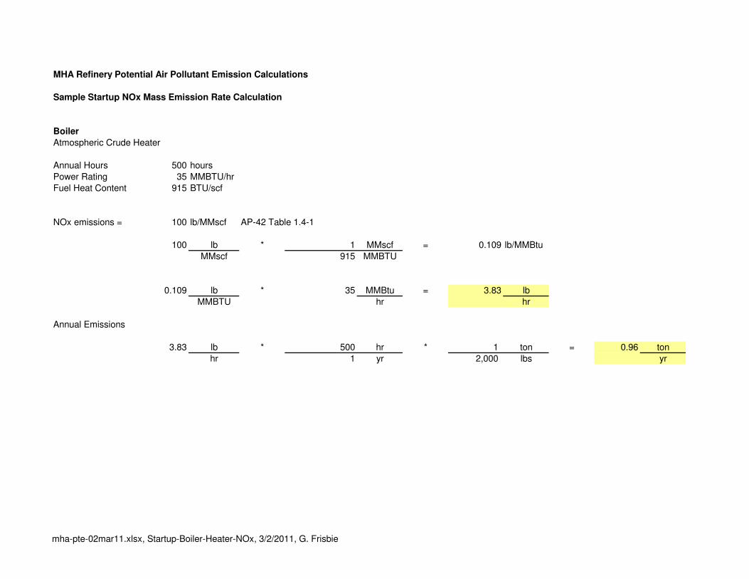
MHA Refinery Potential Air Pollutant Emission Calculations
Sample Startup NOx Mass Emission Rate Calculation
Boiler
Atmospheric Crude Heater
Annual Hours 500 hours
Power Rating 35 MMBTU/hr
Fuel Heat Content 915 BTU/scf
NOx emissions = 100 lb/MMscf AP-42 Table 1.4-1
100 lb * 1 MMscf = 0.109 lb/MMBtu
MMscf 915 MMBTU
0.109 lb * 35 MMBtu = 3.83 lb
MMBTU hr hr
Annual Emissions
3.83 lb * 500 hr * 1 ton = 0.96 ton
hr 1 yr 2,000 lbs yr
mha-pte-02mar11.xlsx, Startup-Boiler-Heater-NOx, 3/2/2011, G. Frisbie

MHA Refinery Potential Air Pollutant Emission Calculations
Sample Normal CO Exhaust Flow and Mass Emission Rate Calculation
Boiler
Atmospheric Crude Heater
Annual Hours 8284 hours
Exhaust Flow 28,216 lb/hr Engineering Data
Exhaust Mol Weight Wet 27.69 lb/lbmol Engineering Data
Exhaust Mol Weight Dry 29.86 lb/lbmol Engineering Data
Exhaust H2O 18.30% Engineering Data
Exhaust O2 Wet 2.45% Engineering Data
Ehaust O2 Dry 3.00% Engineering Data
Ideal Gas Density 358.9337 scf/lbmol
CO Mol Weight 28.01 lb/lbmol
Exhaust Temp 410 deg F
Base Temperature 460 deg F
Standard Temperature 32 deg F
Ambient Pressure 13.59 psi
Standard Pressure 14.70 psi
Exhaust Flow
28,216 lb * 1 lbmol = 1,019 lbmol wet
1 hr 27.69 lb hr
1,019 lbmol wet * 359 scf = 365,822 scf
hr lbmol hr
365,822 scf * ( 460 + 410 ) * 14.70 = 699,843 acf
hr ( 460 + 32 ) 13.59 hr
699,843 acf * 1 hr = 11,664 acf
hr 60 min min
Mass Emission Calculation
Remove H2O from Exhaust
H2O Volume 1,019 lbmol * 18.30% = 186 lbmol H2O
hr
1,019 lbmol - 186 = 833 lbmol exhaust dry
hr
Correct to 3 percent O2
21.00% - 3.00% = 18.00%
21.00% - 3.00% = 18.00%
833 * ( 18.00% ) = 833 lbmol exhaust dry corrected to 3 percent O2
18.00% hr
CO Emissions = 50 ppmvd @ 3 percent O2
833 * 50 = 0.04 lbmol CO
1.00E+06 hr
0.04 lbmol CO * 28.01 lb = 1.2 lb CO
1 hr 1 lbmol hr
10% Contingency 1.2 * ( 1 + 0.10 ) = 1.28 lb CO
hr
Annual Emissions
1.28 lb * 8284 hr * 1 ton = 5.31 ton
hr 1 yr 2,000 lbs yr
mha-pte-02mar11.xlsx, Normal-Boiler-Heater-CO, 3/2/2011, G. Frisbie

MHA Refinery Potential Air Pollutant Emission Calculations
Sample Startup CO Exhaust Flow and Mass Emission Rate Calculation
Boiler
Atmospheric Crude Heater
Annual Hours 500 hours
Exhaust Flow 28,216 lb/hr Engineering Data
Exhaust Mol Weight Wet 27.69 lb/lbmol Engineering Data
Exhaust Mol Weight Dry 29.86 lb/lbmol Engineering Data
Exhaust H2O 18.30% Engineering Data
Exhaust O2 Wet 2.45% Engineering Data
Ehaust O2 Dry 3.00% Engineering Data
Ideal Gas Density 358.9337 scf/lbmol
CO Mol Weight 28.01 lb/lbmol
Exhaust Temp 410 deg F
Base Temperature 460 deg F
Standard Temperature 32 deg F
Ambient Pressure 13.59 psi
Standard Pressure 14.70 psi
Exhaust Flow
28,216 lb * 1 lbmol = 1,019 lbmol wet
1 hr 27.69 lb hr
1,019 lbmol wet * 359 scf = 365,822 scf
hr lbmol hr
365,822 scf * ( 460 + 410 ) * 14.70 = 699,843 acf
hr ( 460 + 32 ) 13.59 hr
699,843 acf * 1 hr = 11,664 acf
hr 60 min min
Mass Emission Calculation
Remove H2O from Exhaust
H2O Volume 1,019 lbmol * 18.30% = 186 lbmol H2O
hr
1,019 lbmol - 186 = 833 lbmol exhaust dry
hr
Correct to 0 percent O2
21.00% - 3.00% = 18.00%
21.00% - 0.00% = 21.00%
833 * ( 18.00% ) = 714 lbmol exhaust dry corrected to 0 percent O2
21.00% hr
CO Emissions = 200 ppmvd @ 0 percent O2
714 * 200 = 0.14 lbmol CO
1.00E+06 hr
0.14 lbmol CO * 28.01 lb = 4.0 lb CO
1 hr 1 lbmol hr
10% Contingency 4.0 * ( 1 + 0.10 ) = 4.40 lb CO
hr
Annual Emissions
4.40 lb * 500 hr * 1 ton = 1.10 ton
hr 1 yr 2,000 lbs yr
mha-pte-02mar11.xlsx, Startup-Boiler-Heater-CO, 3/2/2011, G. Frisbie

MHA Refinery Potential Air Pollutant Emission Calculations
Sample Normal Boiler SO2 Calculation
Boiler
Atmospheric Crude Heater
Annual Hours 8284 hours
Fuel Heat Content (LHV) = 915.0 BTU/scf
Heat Input = 35 MMBTU/hr
Ideal Gas Density 358.9 scf/lbmol
S Mol Weight 32.065 lb
SO2 Mol Weight 64.063 lb
Fuel S Concentration 60 ppmvd
Calculate Fuel Flow
35,000,000 BTU * 1 scf = 38,251 scf
hr 915 BTU hr
Calculate Sulfur Emissions
60 lb-mol S * 32.065 lb S * 1 lb-mol CH4 = 5.36E-06 lb S
1000000 lb-mol CH4 lb-mol S 358.9 scf scf
5.36E-06 lb S * 38,251 scf = 0.205 lb S
scf hr hr
0.2050 lb S * 64 lb SO2 = 0.41 lb SO2
hr 32 lb S hr
10% Contingency 0.41 * ( 1 + 0.10 ) = 0.45 lb SO2
hr
Annual Emissions
0.45 lb * 8284 hr * 1 ton = 1.87 ton
hr 1 yr 2,000 lbs yr
mha-pte-02mar11.xlsx, Normal-Boiler-SO2, 3/2/2011, G. Frisbie

MHA Refinery Potential Air Pollutant Emission Calculations
Sample Startup Boiler SO2 Calculation
Boiler
Atmospheric Crude Heater
Annual Hours 500 hours
Fuel Heat Content (LHV) = 915.0 BTU/scf
Heat Input = 35 MMBTU/hr
Ideal Gas Density 358.9 scf/lbmol
S Mol Weight 32.065 lb
SO2 Mol Weight 64.063 lb
Fuel S Concentration 162 ppmvd
Calculate Fuel Flow
35,000,000 BTU * 1 scf = 38,251 scf
hr 915 BTU hr
Calculate Sulfur Emissions
162 lb-mol S * 32.065 lb S * 1 lb-mol CH4 = 1.45E-05 lb S
1000000 lb-mol CH4 lb-mol S 358.9 scf scf
1.45E-05 lb S * 38,251 scf = 0.554 lb S
scf hr hr
0.5536 lb S * 64 lb SO2 = 1.11 lb SO2
hr 32 lb S hr
Annual Emissions
1.11 lb * 500 hr * 1 ton = 0.28 ton
hr 1 yr 2,000 lbs yr
mha-pte-02mar11.xlsx, Startup-Boiler-SO2, 3/2/2011, G. Frisbie

MHA Refinery Potential Air Pollutant Emission Calculations
Normal and Startup Startup VOC Mass Emission Rate Calculation
Boiler
Atmospheric Crude Heater
Annual Normal Hours 8284 hours
Annual Startup Hours 500 hours
Power Rating 35 MMBTU/hr
Fuel Heat Content 915 BTU/scf
VOC emissions = 5.5 lb/MMscf AP-42 Table 1.4-2
6 lb * 1 MMscf = 0.006 lb/MMBtu
MMscf 915 MMBTU
0.006 lb * 35 MMBtu = 0.21 lb
MMBTU hr hr
Annual Normal Emissions
0.21 lb * 8284 hr * 1 ton = 0.87 ton
hr 1 yr 2,000 lbs yr
Annual Startup Emissions
0.21 lb * 500 hr * 1 ton = 0.05 ton
hr 1 yr 2,000 lbs yr
mha-pte-02mar11.xlsx, Sample-Boiler-Heater-VOC, 3/2/2011, G. Frisbie
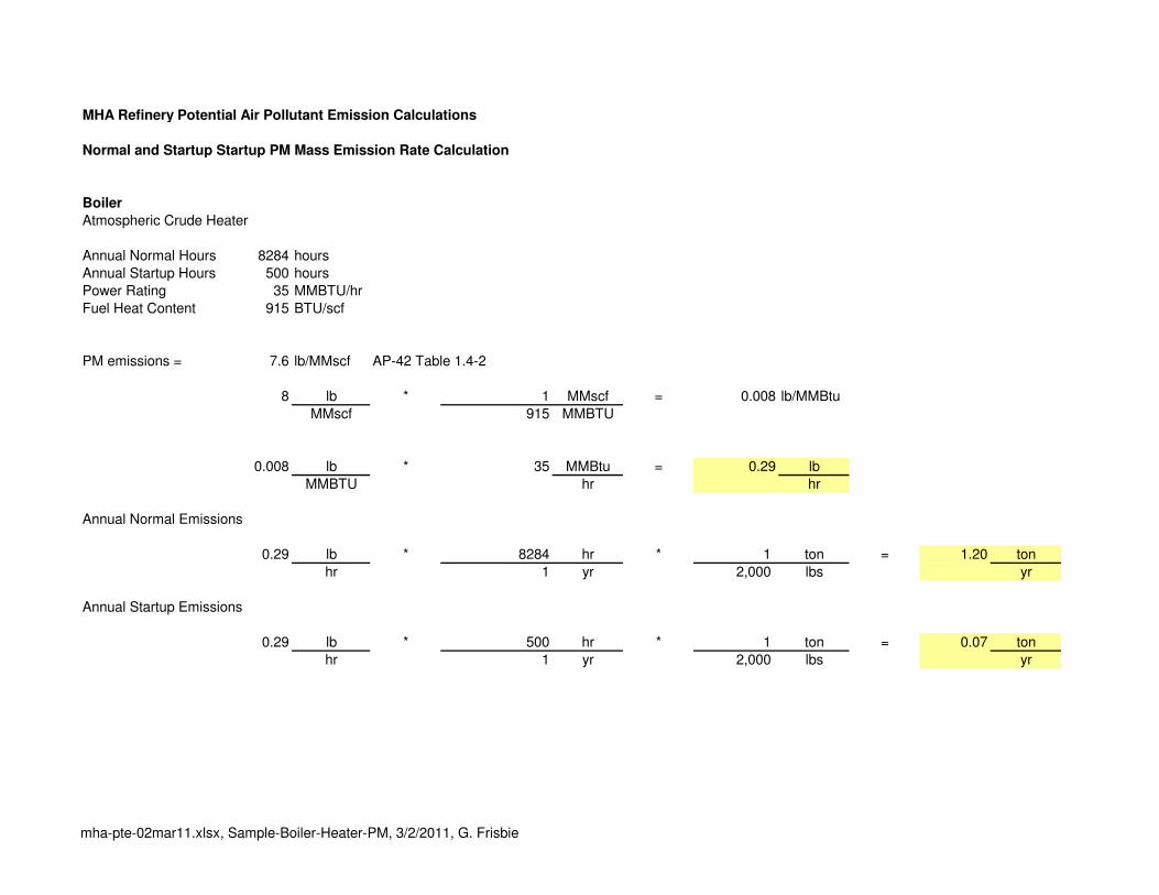
MHA Refinery Potential Air Pollutant Emission Calculations
Normal and Startup Startup PM Mass Emission Rate Calculation
Boiler
Atmospheric Crude Heater
Annual Normal Hours 8284 hours
Annual Startup Hours 500 hours
Power Rating 35 MMBTU/hr
Fuel Heat Content 915 BTU/scf
PM emissions = 7.6 lb/MMscf AP-42 Table 1.4-2
8 lb * 1 MMscf = 0.008 lb/MMBtu
MMscf 915 MMBTU
0.008 lb * 35 MMBtu = 0.29 lb
MMBTU hr hr
Annual Normal Emissions
0.29 lb * 8284 hr * 1 ton = 1.20 ton
hr 1 yr 2,000 lbs yr
Annual Startup Emissions
0.29 lb * 500 hr * 1 ton = 0.07 ton
hr 1 yr 2,000 lbs yr
mha-pte-02mar11.xlsx, Sample-Boiler-Heater-PM, 3/2/2011, G. Frisbie

MHA Refinery
MHA Refinery Potential Air Pollutant Emission Calculations
Tail Gas Exhaust Calculations
Annual Hours 8584
Engineering Estimate of Tail Gas Composition
Exhaust Molecular Emission
Flow Weight Rate
Species (lb-mol/hr) (lb/lb-mol) (lb/hr) (ton/yr)
Ar 0.40 39.948 16.0 68.6
CO 0.17 28.010 4.8 20.4
CO2 9.87 44.009 434.4 1864.3
H2 0.17 2.016 0.3 1.5
H2O 11.08 18.015 199.6 856.7
N2 31.87 28.014 892.8 3831.9
O2 1.59 31.998 50.9 218.4
SO2 0.11 64.063 7.0 30.2
Total Wet 55.26
Total Dry 44.18
SO2 Concentration 2,490 ppmvd
Recalculate SO2 at 3,000 ppmvd
SO2 0.13 64.063 8.5 36.4
mha-pte-02mar11.xlsx, Tail-Gas, 3/2/2011, G. Frisbie

MHA Refinery Potential Air Pollutant Emission Calculations
Flare Normal Emissions
AP-42 Table 13.5-1 (English Units). Emission Factors for Flare Operations
NOx 0.068 lb/MMBTU
CO 0.37 lb/MMBTU
Normal Hours 8684 hours
Fuel S Concentration 5.36E-06 lb S/scf See worksheet "Normal-Boiler-SO2"
Fuel Heat Content 915 BTU/scf
Fuel Heat Input 10 MMBTU/hr
Fuel Rate 0.011 MMscf/hr
Normal Emissions
NOx 0.068 lb * 10 MMBTU = 0.68 lb
MMBTU hr hr
0.68 lb * 8684 hr * 1 ton = 2.95 ton
hr yr 2000 lb yr
CO 0.37 lb * 10 MMBTU = 3.7 lb
MMBTU hr hr
3.7 lb * 8684 hr * 1 ton = 16.07 ton
hr yr 2000 lb yr
SO2 5.36E-06 lb S * 1.00E+06 scf * 0.011 MMscf * 2 lb SO2 = 0.12 lb
scf MMscf hr lb S hr
0.12 lb * 8684 hr * 1 ton = 0.51 ton
hr yr 2000 lb yr
mha-pte-02mar11.xlsx, Flare-Normal, 3/2/2011, G. Frisbie

MHA Refinery Potential Air Pollutant Emission Calculations
Flare Startup Emissions
AP-42 Table 13.5-1 (English Units). Emission Factors for Flare Operations
NOx 0.068 lb/MMBTU
CO 0.37 lb/MMBTU
Startup Hours 100 hours
Fuel Heat Input 10 MMBTU/hr
SRU Capacity 3 long-tons/day
Startup Emissions
NOx 0.068 lb * 10 MMBTU = 0.68 lb
MMBTU hr hr
0.68 lb * 100 hr * 1 ton = 0.03 ton
hr yr 2000 lb yr
CO 0.37 lb * 10 MMBTU = 3.7 lb
MMBTU hr hr
3.7 lb * 100 hr * 1 ton = 0.19 ton
hr yr 2000 lb yr
SO2 3 long-tons S * 2,240 lb S = 6,720 lb S = 280 lb S
day long-tons day hr
280.0 lb S * 2 Mol SO2 = 560.0 lb
hr Mol S hr
560.0 lb * 100 hr * 1 ton = 28.0 ton
hr yr 2000 lb yr
mha-pte-02mar11.xlsx, Flare-Startup, 3/2/2011, G. Frisbie

Updated Fugitive VOC Calculations
Original Storage Tank Total 26.7 ton/yr
2 Decant Oil Tanks 12.56 lb/yr
0.00628 ton/yr
New Storage Tank Total 26.7
Original Area Fugitives 38.02
Assume 20% Increase from New Vacuum Unit 7.604
New Area Fugitive Total 45.6
Updated Fugitive PM Calculations
Original Fugitive Vehicle Traffic PM10 16.74
Assume 20% Increase from New Vacuum Unit 3.348
New Fugitive Vehicle Traffic PM10 Total 20.088

TANKS 4.0.9d
Emissions Report - Summary Format
Tank Indentification and Physical Characteristics
Identification User Identification: Decant Oil Tank 1 City: Bismarck State: North Dakota Company: Type of Tank: Vertical Fixed Roof Tank Description: Decant Oil Tank
Tank Dimensions Shell Height (ft): 40.00 Diameter (ft): 40.00 Liquid Height (ft) : 35.00 Avg. Liquid Height (ft): 25.00 Volume (gallons): 329,011.52 Turnovers: 50.00 Net Throughput(gal/yr): 16,450,576.00 Is Tank Heated (y/n): Y
Paint Characteristics Shell Color/Shade: White/White Shell Condition Good Roof Color/Shade: White/White Roof Condition: Good
Roof Characteristics Type: Dome Height (ft) 5.00 Radius (ft) (Dome Roof) 40.00
Breather Vent Settings Vacuum Settings (psig): -0.03 Pressure Settings (psig) 0.03
Meterological Data used in Emissions Calculations: Fargo, North Dakota (Avg Atmospheric Pressure = 14.25 psia)
Page 1 of 4TANKS 4.0 Report
3/2/2011file://C:\Main\Programs\Tanks\Tanks409d\summarydisplay.htm
Decant Oil Tank 1 - Vertical Fixed Roof Tank Bismarck, North Dakota
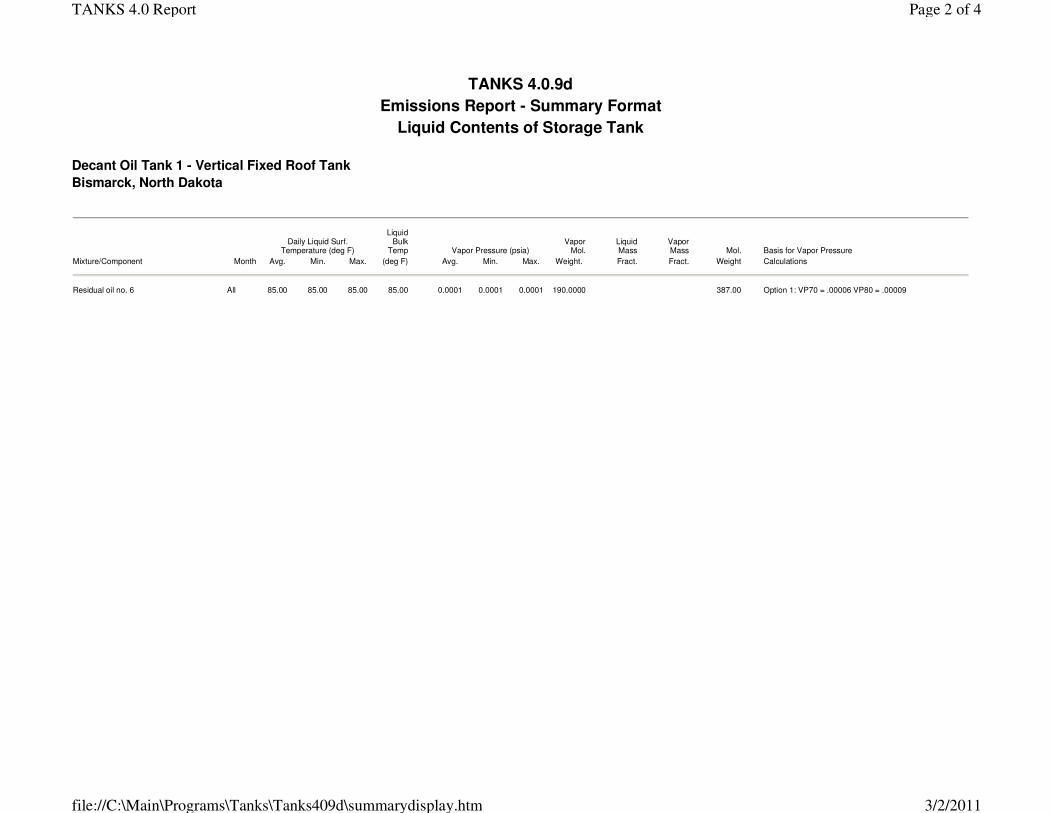
TANKS 4.0.9d
Emissions Report - Summary Format
Liquid Contents of Storage Tank
Daily Liquid Surf.
Temperature (deg F)
Liquid Bulk
Temp Vapor Pressure (psia)Vapor
Mol. Liquid Mass
Vapor Mass Mol. Basis for Vapor Pressure
Mixture/Component Month Avg. Min. Max. (deg F) Avg. Min. Max. Weight. Fract. Fract. Weight Calculations
Residual oil no. 6 All 85.00 85.00 85.00 85.00 0.0001 0.0001 0.0001 190.0000 387.00 Option 1: VP70 = .00006 VP80 = .00009
Page 2 of 4TANKS 4.0 Report
3/2/2011file://C:\Main\Programs\Tanks\Tanks409d\summarydisplay.htm

Emissions Report for: Annual
Decant Oil Tank 1 - Vertical Fixed Roof Tank Bismarck, North Dakota
TANKS 4.0.9d
Emissions Report - Summary Format
Individual Tank Emission Totals
Losses(lbs)
Components Working Loss Breathing Loss Total Emissions
Residual oil no. 6 6.28 0.00 6.28
Page 3 of 4TANKS 4.0 Report
3/2/2011file://C:\Main\Programs\Tanks\Tanks409d\summarydisplay.htm
Related Documents