Page 1 of 10 ADDENDUM #05 PROJECT: Mount Allison University Gairdner Renovations Project PROJECT N o : CFEI-16-01 TP02 DATE: 2017.04.05 This Addendum shall be considered part of the specifications for the construction of this work and shall be read in conjunction with such specifications. All work mentioned herein shall be in addition to and shall supersede the specifications and shall be included in the contractor’s tender. This Addendum shall be read in conjunction with drawings and Specifications Issued for RFP on March 15, 2017. This Addendum has a total of Thirty-four (34) pages including attachments. 1. SPECIFICATIONS 1.1. Reference Section 00 41 13 Proposal Form, dated March 15, 2017. a. Replace Section 00 41 13 Proposal form with Section 00 41 13, dated April 5, 2017. 1.2. Reference Section 06 60 00 Plastic Panelling, dated April 05, 2017. a. Add Specification 06 60 00 Plastic Panelling, dated April 05, 2017, attached. 1.3. Reference Section 08 71 00 Door Hardware, dated March 15, 2017 a. Modify Hardware Set # H-24 – Pair Doors 209.2 to read ‘Hardware Set # H-24 – Pair Doors 209A’ b. Modify Hardware Set # H-12 – Pair Doors #B17.1 i. Remove Requirement for Card Reader, Power Transfer, and Electric Strike. ii. Existing Door Sensors to be reinstalled. c. Delete Hardware Set # H-15 i. Door B17.5 is existing and will retain its current hardware. d. Modify Hardware Set # H-1, H-11 i. Replace electric strike Von Duprin with HES 8000 series. e. Provide Hardware set #H-14 for Pair Doors #302.1 1.4. Reference Section 07 43 42 Composite Metal Building Panels, dated April 3, 2017. a. Add acceptable manufacturer under item 2.1.2 Alucoil North America

Welcome message from author
This document is posted to help you gain knowledge. Please leave a comment to let me know what you think about it! Share it to your friends and learn new things together.
Transcript

Page 1 of 10
ADDENDUM #05
PROJECT: Mount Allison University Gairdner Renovations Project PROJECT No: CFEI-16-01 TP02 DATE: 2017.04.05
This Addendum shall be considered part of the specifications for the construction of this work and shall be read in conjunction with such specifications. All work mentioned herein shall be in addition to and shall supersede the specifications and shall be included in the contractor’s tender. This Addendum shall be read in conjunction with drawings and Specifications Issued for RFP on March 15, 2017. This Addendum has a total of Thirty-four (34) pages including attachments.
1. SPECIFICATIONS
1.1. Reference Section 00 41 13 Proposal Form, dated March 15, 2017.
a. Replace Section 00 41 13 Proposal form with Section 00 41 13, dated April 5, 2017.
1.2. Reference Section 06 60 00 Plastic Panelling, dated April 05, 2017. a. Add Specification 06 60 00 Plastic Panelling, dated April 05, 2017, attached.
1.3. Reference Section 08 71 00 Door Hardware, dated March 15, 2017
a. Modify Hardware Set # H-24 – Pair Doors 209.2 to read ‘Hardware Set # H-24 – Pair Doors 209A’
b. Modify Hardware Set # H-12 – Pair Doors #B17.1 i. Remove Requirement for Card Reader, Power Transfer, and Electric
Strike. ii. Existing Door Sensors to be reinstalled.
c. Delete Hardware Set # H-15 i. Door B17.5 is existing and will retain its current hardware.
d. Modify Hardware Set # H-1, H-11 i. Replace electric strike Von Duprin with HES 8000 series.
e. Provide Hardware set #H-14 for Pair Doors #302.1
1.4. Reference Section 07 43 42 Composite Metal Building Panels, dated April 3, 2017. a. Add acceptable manufacturer under item 2.1.2 Alucoil North America

Page 2 of 10
1.5. Reference Section 08 45 23 Translucent Panel Wall and Roof Assemblies, dated April 3, 2017.
a. Modify item 2.3.1.1 to read ‘Thickness 2 ¾’ b. Modify item 2.3.1.2 to read ‘Panel U-factor of .14 (R=7.5) by NFRC certified
laboratory: 69.85 mm (2 3/4inch) thermally broken grid.’
1.6. Reference Section 08 80 50 Glass and Glazing, dated March 15, 2017 a. Add item 2.2.3 as follows:
i. TRANSLUCENT GLAZING UNITS (TGU) 1. The Translucent Glazing Unit shall be of a design such as to
present a monolithic glass section without visible internal framing, support or other solid member inside of the perimeter spacer.
2. Standard of Acceptance: Solera L R2.2 3. Air filled preassembled units consisting of:
a. Two lites of glass; b. Translucent, veils attached to both glass surfaces; c. Continuous perimeter warm edge spacer bar with
integral 40% dessicant. d. Secondary seal of two part structural silicone e. Glazing unit shall not contain in excess of .01 parts per
million by weight each of Volatile Organic Compounds, asbestos, resorcinol-formaldehyde, pheono-resorcinol formaldehyde, urea formaldehyde, CFC, HFC, HCFC, Halon, Benzene, Cadmium (and compounds, Carbon tetrachloride, Cyanide (and compounds) Toluene, Xylenes, Lead. 1,1,1,Trichlorethane, Trichlorethylene, MEK, and MIK
4. Overall thickness and size: Thickness: 1”. 5. Thermal insulation (U-value): 0.47(Btu/hr·ft²·°F) 6. Daylight transmittance: 62 % 7. Daylight to solar heat gain ratio: LSG=1.08 8. Solar heat gain coefficient (no shade): SHGC=0.58 9. Glass: Type GL-1.
1.7. Reference Section 9 51 13 Acoustic Panel Ceilings, dated March 15, 2017.
a. Add item 2.1.3 Acoustical Tile Type ACT2. i. Product: CGC Clean Room Tile Acoustical Panels
ii. 2’x2’x5/8” iii. Square edge iv. NRC .55 v. Min CAC 35
vi. Acceptable equivalent product by Armstrong. vii. Suspension System: CGC Donn BRAND CE™ 1-1/2" ACOUSTICAL
SUSPENSION SYSTEM rated for Class 100 clean room environments per Federal Standard 209(e) or equivalent product by Armstrong.
viii. Trims: Edge trims and wall angles ix. Wire: As recommended by manufacturer
Page 3 of 10
b. Add item 2.14 Acoustical Tile Type ACT3. i. Product: CGC ECLIPSE HIGH-NRC ACOUSTICAL CEILING PANEL
ii. 2’x2’x5/8” iii. Square edge iv. NRC .70 v. Min CAC 35
vi. Suspension System: CGC Donn DX or equivalent by Armstrong. vii. Trims: Edge trims and wall angles
viii. Wire: As recommended by manufacturer.
1.8. Reference Section 09 67 23 Resinous Flooring issued in Addendum 02 dated March 28, 2015.
a. Add item 2.1.2.2 Acceptable Manufacture BASF
1.9. Reference Section 12 32 00 Manufactured Wood Casework dated March 15, 2017. a. Add item 2.1.2.4 Provincial Lab Systems Limited
1.10. Reference Section 13 21 26 Cold Room Storage, dated April 5 2017.
a. Add Section 13 21 26 Cold Room Storage, dated April 5 2017, attached.
1.11. Reference Section 14 21 23 Elevators, dated March 15, 2017 a. Modify Item 1.3.2.5 to read: Total Rise 23’6” b. Item 2.5.6: Add Acceptable elevator product: Ottis Gen-2 c. Item 2.7.1.1: Delete single speed side opening doors and replace with center
opening doors. d. Item 2.14.5: Delete reference to DA-14 drawing.
1.12. Reference 23 05 75 Thermal Insulation for Piping
a. Part 3.6.7.3 should read: Concealed, indoors: Canvas ASJ b. Part 3.6.7.4 should read: Steam Systems: Canvas jacket Aluminium jacket.
1.13. Reference Section 23 33 16 Item 2.2.11
a. Fire Dampers; Approved alternate manufacturer: Alumavent.
1.14. Reference Section 23 22 14 a. Approved Manufacturer: Watson McDaniel, Armstrong, Spirax Sarco, Apollo. b. Part 2.2: Inverted Bucket type traps to be used in lieu of F&T type.
1.15. Reference Section 33 16 00 Saltwater Storage Tank, dated April 05, 2017.
a. Add Section 33 16 00 Saltwater Storage Tank, dated April 05, 2017, attached.

Page 4 of 10
2. DRAWINGS
2.1. Reference Drawing C1.01 a. Add note at new well as follows:
i. Well to be supplied and installed by owner. Contractor responsible to provide 25mm dia. Pex-A supply line and connection to building
2.2. Reference Drawings A1.01 and A1.02 Floor Plans
a. Reference hatched region indicating concrete topper on First and Second Floor Plans
i. Revise legend note to read: Extent of approximately 2” concrete slab topper. Make flush with existing slab and terrazzo. Slope to drains as indicated, refer to enlarged plans. Concrete topping to be 30 MPa mix with maximum 1/2” aggregate and a bonding agent on the existing slab.
2.3. Reference Drawings A.101, A1.02, A6.03, A6.04
a. Provide and install Expansion Joint in Floor Slabs along Gridline L in South Stair on every floor.
b. Provide tile movement joint along gridline L in South Stair on every level.
2.4. Reference Drawings A1.01, A6.03, A6.04, A7.03 a. Delete all References to Corner Guards and Bumper Rails. Remove From Scope
of Work.
2.5. Reference Drawings A1.21 and A1.22 Reflected Ceiling Plans a. Sprayfoam Insulation to run continuous perimeter of underside of first and
second floor slabs as indicated in details 3 and 6/A5.51. Gypsum Wall Board Bulkheads to occur only where indicated on Reflected Ceiling Plans.
2.6. Reference Drawings A6.02 Door and Screen Schedule, dated March 15, 2017
a. Modify Comments for Door B09.1 as follows: i. Door, frame and hardware by cold storage room manufacturer, refer to
specification 13 21 26 Cold Storage Room, attached.
2.7. Reference Drawing A5.51 Exterior Section Details a. Replace detail 1/A5.51 with Detail 1 on ASK.03, dated April 5, 2017, attached.
2.8. Reference Drawings A8.02- A8.05
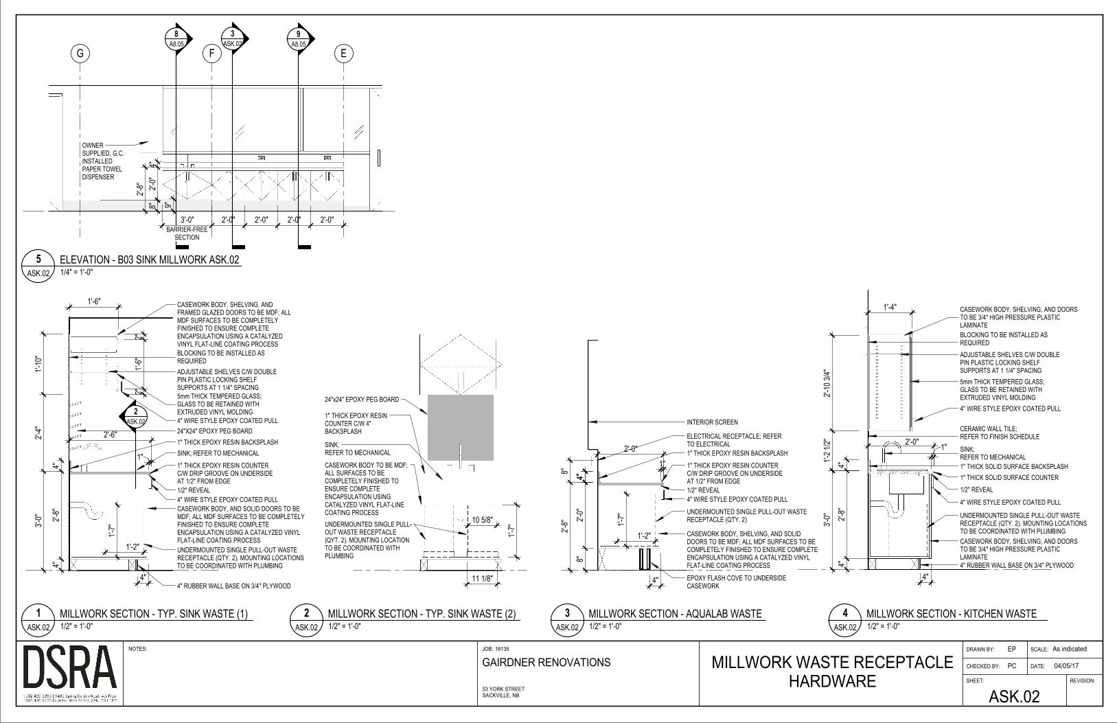
a. Modify Drawings in accordance with ASK.02, dated April 5, 2017, attached. i. Replace Millwork Elevation 6/A8.02 with 5/ASK.02
ii. Replace detail 2/A8.05 with new millwork detail 1/ASK.02 iii. Replace detail 28/A8.05 with new millwork detail 4/ASK.02
b. Millwork Waste Receptacle hardware to be Wire Waste Bin System, Single 503.88.990 by Hafele, complete with steel hardware and bin. Load bearing capacity (88 lbs) 40 kg.
2.9. Reference Sketch ASK-01, dated April 5, 2017. a. Replace Detail 1/A5.51 with detail 1 on sketch ASK-01, attached.

Page 5 of 10
2.10. Reference Sketch ASK-03, dated April 5, 2017.
a. Replace Detail 8/A5.61with detail 1 on sketch ASK-03, attached.
2.11. Reference Dwg. M1.00
a. Clarification note 4: ”All drainage and vent piping upstream of acid neutralization tank and downstream of lab sinks shall be polypropylene acid waste pipe.”
b. Waste & vent pipe beyond this point (i.e. waste line extending into mechanical room B18), need not be acid resistant type.
c. Add P-7A type floor drain at rear of Autoclave and allow for trap prime feed.
2.12. Reference Dwg. M1.02
a. Clarification: Sink Fixture P-3A is not shown on dwg M1.02, however should be furnished as shown on dwg M1.06.
2.13. Reference Dwg. M1.08
a. Clarification: Sprinkler System serving Gairdner begins and includes 6” backflow assembly of Detail 2/M1.08 Water Entrance Detail. General Contractor to determine subcontractor responsible for installation of 6” water service thru tunnel and connection to main tunnel utility.
2.14. Reference Dwg. M2.00
a. Provide FireWrap Insulation installed as per detail 5/M2.06 for 12”dia. Fume Hood Exhaust (FH-1) in lab B13, at penetration of rated duct shaft. Extend FireWrap insulation 10 feet beyond fire separation as per NFPA 7.10.3.1.
b. Provide12”x6” transfer air duct c/w Fire damper above ceiling between corridor B00 and Lab B13.
c. Provide one type R2 perforated ceiling return grille in t-bar lay-in ceiling of corridor B00 west.
d. Provide12”x6” transfer air duct c/w Fire damper above ceiling between corridor B00 and Lab B03.
e. Provide one type R2 perforated ceiling return grille in t-bar lay-in ceiling of corridor B00 east.
f. Delete Fire Damper in 6” exhaust air branch duct between Corridor B03 & Washroom B02.
g. Add Fire Damper in 6” exhaust air branch duct between Washroom B02 & Custodial Storage B10.

Page 6 of 10
2.15. Reference Dwg. M2.01
a. Provide FireWrap Insulation installed as per detail 5/M2.06 for 10”dia. Fume Hood Exhaust (FH-2) in lab 107, at penetration of rated duct shaft. Extend FireWrap insulation 10 feet beyond fire separation as per NFPA 7.10.3.1.
b. Add 12”dia. Fire Damper for General Lab Exhaust in lab 107, at penetration of rated duct shaft.
c. Provide12”x6” transfer air duct c/w Fire damper above ceiling, between corridor 100 and Lab 107. Provide Grille type R5, EH Price model 530 on lab side wall.
d. Provide FireWrap Insulation installed as per detail 5/M2.06 for 10”dia. Fume Hood Exhaust (FH-4) in lab 101, at penetration of rated duct shaft. Extend FireWrap insulation 10 feet beyond fire separation as per NFPA 7.10.3.1.
e. Add 12”dia. Fire Damper for General Lab Exhaust in lab 101, at penetration of rated duct shaft.
f. Provide12”x6” transfer air duct c/w Fire damper above ceiling, between corridor 100 and Lab 101. Provide Grille type R5, EH Price model 530 on lab side wall.
g. Delete Fire Damper in 4” fresh air duct at gridline H, serving room 105, FC-12.
h. Add 8”x10” Fire Damper in FC-12 supply air duct between room 105 & 107A. Add 10”x8” Fire Damper in FC-12 return air duct between room 105 & 107A.
i. Delete Fire Damper in 4” fresh air duct at gridline D, serving room 109, FC-15.
j. Add 8”x10” Fire Damper in FC-15 supply air duct between room 109 & 107D. Add 12”x6” Fire Damper in FC-15 return air duct between room 109 & 107D.
k. Delete Fire Damper in 4” fresh air duct at gridline H, serving room 103, FC-20.
l. Add 8”x10” Fire Damper in FC-20 supply air duct between room 103 & 101D. Add 8”x8” Fire Damper in FC-20 return air duct between room 103 & 101D.
m. Delete Fire Damper in 8”x10” FC-17 supply air duct at gridline D, serving vestibule 100A. Delete Fire Damper in 12”x8” return transfer duct at gridline H, of vestibule 100A.
n. Delete Fire Damper in 6”dia. FC-21 supply air branch duct to room 106.
o. Add Fire Damper in 8”dia. supply air branch duct serving room 110.
2.16. Reference Dwg. M2.03
a. Provide FireWrap Insulation installed as per detail 5/M2.06 for 10”dia. Fume Hood Exhaust (FH-3) in lab 209/211, at penetration of rated corridor wall as per NFPA 7.10.3.1; extend wrap thru mezzanine mechanical room wall terminating at fume hood plenum.
b. Add 12”dia. Fire Damper for General Lab Exhaust in lab B107, at penetration of rated duct shaft.
c. Provide FireWrap Insulation installed as per detail 5/M2.06 for 10”dia. Fume Hood Exhaust (FH-5) in lab 203-1, at penetration of rated corridor wall as per NFPA 7.10.3.1; extend wrap thru mezzanine mechanical room wall terminating at fume hood plenum.

Page 7 of 10
d. Add 12”dia. Fire Damper for General Lab Exhaust in lab B107, at penetration of rated duct shaft.
e. Provide12”x6” transfer air duct c/w Fire damper above ceiling, between corridor 200 and Lab 211. Provide Grille type R5, EH Price model 530 on lab side wall.
f. Provide12”x6” transfer air duct c/w Fire damper above ceiling, between corridor 200 and Lab 209. Provide Grille type R5, EH Price model 530 on lab side wall.
g. Provide12”x6” transfer air duct c/w Fire damper above ceiling, between corridor 200 and Lab 203-1. Provide Grille type R5, EH Price model 530 on lab side wall.
h. Provide two type R2 perforated ceiling return grille in t-bar lay-in ceiling of corridor 200 (east and west sides).
i. Clarification: Delete all Fire Dampers shown on exhaust ducts along gridline G.5 which are contained within the rated bulkhead at ceiling run between skylights (see architectural detail & detail 2/M2.04). Provide Fire Dampers on general lab Exhaust ducts only (2 such) where they penetrate Mezzanine mechanical room art gridline 9 (1 such from lab 107)) and gridline 7 (1 such from lab 101). No Fume Hood Exhaust ducts are permitted to have Fire Dampers per NFPA 7.10.3.1 and shall be insulated with FireWrap accordingly.
j. Provide Fire Dampers for general exhaust ducts (4 such which are not enclosed in fire rated bulkhead) serving labs 209/211 & 203-1 where such penetrate the corridor and mezzanine walls.
k. Except where noted otherwise herein, provide Fire Dampers in accordance with all fire separations and as indicated on drawings M2.00 thru M2.03.
2.17. Reference Dwg. M2.09
a. Air Handler Schedule 2/M2.09, AHU-1: Correction: Shall provide a minimum 2000cfm at E.S.P. of 0.7”. Approved alternate manufacturer: Engineered Air.
b. Fume Hood Schedule 1/M2.09: Correction: Change FH-3 model to MOTT 7421002. This unit shall be a constant volume unit. All Fume Hoods shall be supplied with twin under storage cabinets for containment of both Acid storage (non-flammable) and Solvent Storage (flammable), respectively.
c. Fresh Air Intake Hood Schedule 5/M2.09: Acceptable alternate manufacturer: Ventex.
d. Exhaust Fan Schedule: Acceptable alternate manufacturer: ACME Eng & Mfg.
2.18. Reference Dwg. M3.00
a. Clarification: Provide Steam & Condensate branches to Autoclave as per schematic 1/M1.10.
2.19. Reference Dwg. M3.08
a. Chiller Schedule: CH-1A (Aqualab Chiller); Delete reference model Daikin AMZ015. Chiller shall be process type outdoor air cooled chiller capable of year round operation (100% integrated free cooling) to -20°F OAT. Motivaire model MLC-FC-2200 with minimum capacity of 180mbh at 44°F LWT / 55°F EWT / 95°FAmbient.

Page 8 of 10
2.20. Reference Drawing E0.01 details 2 and 3:
a. Add general note as: Pressure treated lumber to be supplied and installed by general contractor.
2.21. Reference Drawing E0.01, detail 1: a. Add general note as: All core drilling to be performed by the general contractor,
electrical contractor shall coordinate locations with general contractor.
2.22. Reference Drawing E3.01, luminaire schedule: a. Add note 2 as: Approved alternate manufacturers: Lithonia Lighting.
2.23. Reference SKE-03:
a. SKE-03R2 shall replace SKE-03 previously issued by addendum.
2.24. Reference E2.01 and E2.02: a. Mounting heights of laboratory receptacles in basement, first and second floors
shall be coordinated with mill work shop drawings which will be available after tender closing date. Exact location and mounting heights to be coordinated during construction.
3. CLARIFICATIONS
3.1. Reference Architectural Drawings a. New copper does NOT need to be aged to match existing conditions.
3.2. Reference Drawings A3.01 and A3.02
a. Reference Floor Assembly F-EX. Remove 3/8” concrete overlayment from assembly.
b. 3/8” cementitious self-levelling floor overlayment by Epoxy flooring sub contractor and at Epoxy flooring locations only as indicated on the Finish Schedule and Finish Floor Plans A6.03 and A6.04.
3.3. Reference Drawing A5.61 Exterior Plan Details a. Detail 9/ A5.61 to receive parging over aluminum column cover similar to
concrete column in detail 6/A5.61. b. Parging mix is to be thin to medium parge: 5 sand, ½ portlant cement, ½
masonry cement, 3 gal water to 1 gal latex. Colour by architect.
3.4. Reference Drawing A6.03 and A6.04 Finish Schedule and Finish Floor Plans a. Tack board sizes and locations are indicated on A6.03 and A6.04 Finish Floor
Plans.
3.5. Equipment Clarification a. EQ 28 Eye Wash/ Shower station is identified in the Plumbing Schedule.

Page 9 of 10
3.6. Equipment Supply Clarification
a. General Contract to include supply and installation of Autoclave gravity steam sterilizer. Unit shall be GETINGE model 522LS, Cabinet type (non –recessed) with Single Manual Door w/ BSF (Biological Sealing Flange) at common Control/Load end. Integral Printer located at control end is standard. Control panel shall be located on unit (integral, not remote mounted). Unit shall be ‘English Language’ model. Steam source shall be ‘House’ supplied steam’ as per mechanical drawings. Integral steam boiler is NOT required (all associated options are not applicable (boiler safety devices and blowdown not required, water saver not required, vacuum pump not applicable). Water booster NOT required. Hot water feed NOT required. Compressed Air not required. 304SS piping for Tissue Culture NOT required. UPS NOT required. Unit shall be supplied with internal rack w/ extra third shelf. Unit shall be supplied with one Loading Car with interior track and one transfer carriage. Seismic anchoring is NOT required. Unit shall comply with Pressure Vessel Code and bear applicable CRN number/documents. Unit shall be supplied with 1”dia. 45psi ‘House Steam’ line and ¾”dia. low pressure condensate as per schematic 1/M3.10. As per dwg M1.05, unit is fed with ¾” cold water feed (downstream of BFP). Unit electrical requirements are 120V/1, 12A, 15MOP. Verify model options with owner prior to final purchase order of equipment.
3.7. Proposal Clarifications a. Proposal Form 00 41 13 is due at the specified closing day and time, 1 original
bid form and bond/bid cheque to be received at Financial Services; amendments can be faxed (506)364-2216 or emailed ([email protected]) until the specified closing time. Amendments to a submission will not be accepted after the original closing date and time.
b. Up until 24 hours from the specified closing day and time submit 5 exact copies of Proposal submission and the requested info specified Section 00 21 13 under Article 6.1 (Appendix “C”), 6.2.1, 6.2.2, 6.2.3 (Appendix “B”), 6.2.4, 6.2.7 and 6.2.8: including, staffing information including resume’s, detailed Schedule of Values with financial breakdown by trade section, and detailed construction schedule and any other required document of the RFP. In case of a discrepancy between the original and the copies, the original and any valid amendment received will prevail.
c. Current list of pre-qualified sub-contractors that have expressed interest in the CFEI-16-01-TP#2 project can be found on the MTA website at https://www.mta.ca/Community/Administrative_departments/Financial_Services/Contractors_and_vendors/Open_tenders/Open_tenders/
d. Proponents are responsible to ensure that they have received ALL addenda and Appendices by visiting the Mount Allison Website prior to submitting their proposal.

Page 10 of 10
4. ATTACHMENTS
4.1. Specification Section 06 60 00 Plastic Panelling
4.2. Specification Section 13 21 26 Cold Storage Room
4.3. Specification Section 33 16 00 Saltwater Storage Tank, dated April 5, 2017.
4.4. Architectural Sketches ASK.01- ASK.03 , dated April 5, 2017
4.5. Electrical Sketch ESK.03 R2, dated April 3, 2017
END OF ADDENDA #05
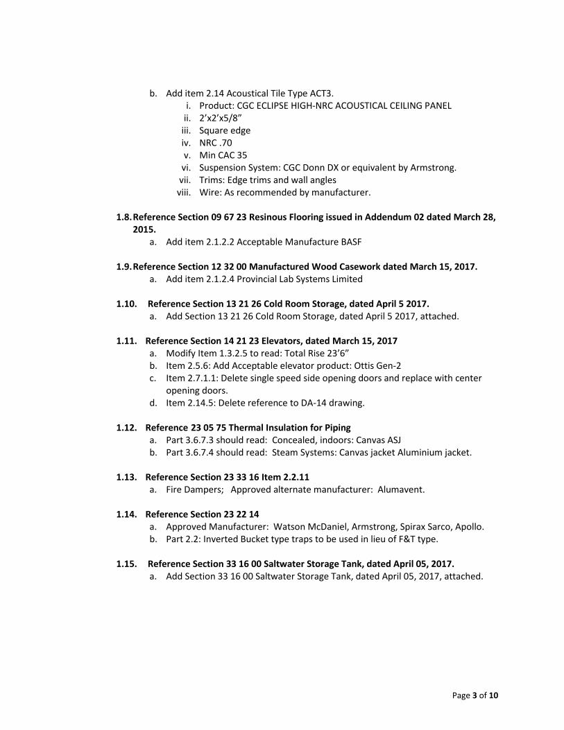
Mount Allison University Proposal Form Section 00 41 13 Gairdner Building Project Page 1 Project # CFEI-16-01-TP#2 April 05, 2017
MTA Contract Documents - Updated April 05, 2017
Proposal Form LUMP SUM Gairdner Building project – RFP# CFEI-16-01-TP#2
Mount Allison University
Bid Submitted by:
Name of Firm:
Address:
Phone and Cell #’s:
Fax #:
Contact Name:
E-mail Address:
Date:
To: Mount Allison University
Financial Services Department Centennial Hall, Room 310 65 York Street Sackville, NB E4L 1E4 Attn: Ruth Terrio, Manager Procurement Services Fax: 506-364-2216
1. Instructions to Proponents 2. Construction Contract Documents 3. Specifications 4. Drawings 5. Schedules 6. All Addenda issued
The undersigned Proponent further agrees to provide all necessary equipment, tools, labour, incidentals and other means of construction to do all the Work and furnish all materials of the specified requirements which are necessary to complete the work in accordance with the contract and agrees to accept, therefore, as payment in full including all

Mount Allison University Proposal Form Section 00 41 13 Gairdner Building Project Page 2 Project # CFEI-16-01-TP#2 April 05, 2017
MTA Contract Documents - Updated April 05, 2017
prime costs, allowances, (HST excluded) including all necessary trade permits, in accordance with above itemized documents for the following total stipulated Lump Sum Price: LUMP SUM PRICE All Work as described in drawings, contract documents and specifications:
Dollar Amount - Write out in Full
Total $ Figures
$
Dollars .00 (HST excluded)
HST @ 15%
$
Total
$
Unit Prices: The following is a list of Unit Prices and forms part of the Contract, upon the acceptance of any or all of the Unit Prices. These Unit Prices may be used in determining the value of a change and do not include HST.
Item
Amount $
Unit Price #1: Masonry Repairs: Replace, Grout, Repoing any existing damaged
masonry units as per S1.01.
$ /sqft
Unit Price #2: Slab/ Concrete honeycombing repairs as per S1.01. Per location of
repair (approx. 12”x12”)
$ /unit
The undersigned Proponent hereby agrees not to revoke this Proposal until: 1. Owner has entered into a Contract with another Proponent for the performance of the Work, per Section 00
21 13 - Instruction to Proponents or,
2. Sixty (60) days after the time fixed in the Instructions to Proponents for receiving Proposals is expired, whichever occurs first; provided, however, that the Proponent may revoke his Proposal at any time before the time fixed in the Instructions to Proponents for receipt of Proposals has expired, upon receipt by Owner from the Proponent of written notice of such revocation before said time has expired.
SECURITY FOR PROPOSAL Each Proponent shall submit with his bid either, .1 A Bid Bond from a recognized Surety Company licensed to do business in the Province of New Brunswick in
the amount of ten per cent (10%) of the Bid, and Agreement to Bond in the form of a letter from a recognized
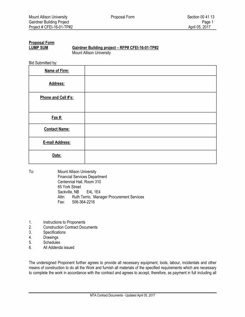
Mount Allison University Proposal Form Section 00 41 13 Gairdner Building Project Page 3 Project # CFEI-16-01-TP#2 April 05, 2017
MTA Contract Documents - Updated April 05, 2017
Surety Company licensed to do business in the Province of New Brunswick, both issued in favour of Mount Allison University, or
.2 A Certified Cheque from a recognized Canadian Chartered Bank in the amount of ten per cent (10%) of the
bid amount, made payable to Mount Allison University SUBSTANTIAL PERFORMANCE DATE: If this Bid is accepted, we shall complete the Work Bid in (Provide the total number of weeks required from date of Contract award until Substantial Performance in table below) weeks and as per the Project Schedule.
Substantial Performance Date
Weeks until Substantial Performance from issuance of PO
LIST OF SUB-CONTRACTORS AND SUPPLIERS:
Division
Sub-contractor
Contact

Mount Allison University Proposal Form Section 00 41 13 Gairdner Building Project Page 4 Project # CFEI-16-01-TP#2 April 05, 2017
MTA Contract Documents - Updated April 05, 2017
ADDENDA We hereby acknowledge receipt of the following Addenda
Addendum No.
Dated
No. of Pages
The undersigned Proponent declares that his Proposal is made without connection with any other person or persons submitting Proposals for the same work, and is in all respects, fair and without collusion or fraud Dated this Day of , 2017
Authorized Signing Officer (Type Full Name)
Title
Registered Company Name
Seal

Mount Allison University 06 60 00
Gairdner Building Renovations PLASTIC PANELLING Page 1 of 5
MTA No. CFEI-16-01-TP#02 April 3, 2017
Part 1 General
1.1 SECTION INCLUDES
.1 This section includes labor, materials and other services necessary to complete
Un-plasticized-polyvinyl chloride (PVCu) wall panel covering at whiteboards.
1.2 RELATED SECTIONS
.1 Section 04 26 19 – Reinforced Unit Masonry.
.2 Section 06 10 13 - Wood Blocking and Curbing: Wood blocking and supports for
steel stud framing.
.3 Section 07 92 00 - Joint Sealants: Perimeter sealant to adjacent construction.
.4 Section 09 22 16 - Non-Structural Metal Stud Framing: Support for Plastic
Panelling.
.5 Section 09 91 10 - Painting: Field paint finish.
.6 Section 22 42 01 - Plumbing Specialties: Plumbing service and drains.
1.3 SUBMITTALS FOR REVIEW
.1 Section 01 33 00: Submission procedures.
.2 Product Data: Provide data on specified component products.
.3 Shop Drawings: Indicate material dimensions, adjacent construction, materials,
thicknesses, fabrication details, required clearances, field jointing, tolerances,
colours, finishes, methods of support, integration of plumbing electrical
components, and anchorages.
.4 Samples: Submit two (2) samples, 150 x 300 mm (6 x 12inch) in size illustrating
colour, texture, and finish.
1.4 SUBMITTALS FOR INFORMATION
.1 Section 01 33 00: Submission procedures.
.2 Installation Data: Manufacturer's special installation requirements.
1.5 CLOSEOUT SUBMITTALS
.1 Section 01 78 00: Submission procedures.
.2 Maintenance Data: Include instructions for stain removal, surface and gloss
restoration.
.3 Maintenance Data: Include instructions for regular cleaning and stain removal.
1.6 QUALITY ASSURANCE
.1 Products of This Section: Manufactured to ISO 9000 certification requirements.
Mount Allison University 06 60 00
Gairdner Building Renovations PLASTIC PANELLING Page 2 of 5
MTA No. CFEI-16-01-TP#02 April 3, 2017
.2 Manufacturer Qualifications: Company specializing in manufacturing the
Products specified in this section with minimum five (5) years documented
experience.
.3 Installer Qualifications: Installer specializing in performing the work of this
section with minimum three (3) years documented experience and approved by
the manufacturer. Contractor to submit names and experience of individuals
performing the work of this section.
1.7 REGULATORY REQUIREMENTS
.1 Conform to applicable code for a flame rating of 25and smoke developed rating
of 50in accordance with CAN/ULC-S102 requirements.
1.8 MOCK-UP
.1 Section 01 43 00: Requirements for mock-up.
.2 Construct mockup approximately 3000 mm x 2000 long wide up including trim
and accessories.
.3 Locate where directed by Consultant.
.4 Mock-up may remain as part of the Work.
1.9 DELIVERY, STORAGE, AND PROTECTION
.1 Section 01 61 00: Transport, handle, store, and protect products.
.2 Comply with manufacturer’s ordering instructions and lead time requirements to
avoid construction delays.
.3 Deliver materials in manufacturer’s original, unopened, undamaged containers
with identification labels intact.
.4 Store materials protected from exposure to harmful weather conditions, at
temperature and humidity conditions recommended by manufacturer.
.5 Store panels in temperature controlled environments. Leave protective film on
panel until ready to use.
1.10 ENVIRONMENTAL REQUIREMENTS
.1 Section 01 35 43: Environmental conditions affecting products on site.
.2 Temperature Requirements: If storage temperature is below 18 degrees C, the
PVCu wall panel must be moved to a warmer place and allowed to reach this
temperature before installation.
.3 Maintain air temperature and structural base temperature at installation area
between 18 C and 26 C for 48 hours before, during and 24 hours after installation.
1.11 WARRANTY
.1 Manufacture to provide a twenty-year product warranty commencing on Date of
Substantial Completion.

Mount Allison University 06 60 00
Gairdner Building Renovations PLASTIC PANELLING Page 3 of 5
MTA No. CFEI-16-01-TP#02 April 3, 2017
.2 Refer also to warranties required per Section 00 52 13 General Conditions.
Part 2 Products
2.1 MANUFACTURERS
.1 Altro; Product: Altro Whiterock Hygienic Wall Covering and Whiteboards.
.2 Other acceptable manufacturers offering functionally and aesthetically equivalent
products.
.1 PALRAM; Product: PALCLAD Pro.
.3 Substitutions: Refer to Section 01 62 00.
2.2 MATERIALS
.1 100% pure vinyl, extruded, semi-rigid, homogenous PVCu sheet. Containing no
plasticizers or fillers.
.1 Thickness: 2.5 mm (0.10 inch);
.2 Panel Width: 1.22m (4 feet)
.3 Panel Height: Either 2.5m or 3m (8 feet or 10 feet);
2.3 FINISHES
.1 Colour: Selected by Architect from Standard Range.
.2 Texture: smooth.
2.4 ACCESSORIES
.1 Panel Jointing:
.1 Vinyl welding rod:
.1 Manufacturer approved weld rod – Colour matched to panel.
.2 Joint Strips Not to be used.
.2 Start and Edge Trim:
.1 Located at perimeter terminations only.
.3 Adhesive:
.1 Two-part resin-based polyurethane adhesive as recommended by
Manufacturer.
.4 Caulking and Sanitary Sealant Compounds:
Supply and install as recommend by Panel Manufacturer.
.1 PVC flexible joint material.
.2 Adhesives and sanitary sealants.
.5 Wall Insert Shelf Unit

Mount Allison University 06 60 00
Gairdner Building Renovations PLASTIC PANELLING Page 4 of 5
MTA No. CFEI-16-01-TP#02 April 3, 2017
.1 Pre-molded PVC Shelf unit approximately 325 x 325 x 100 mm
(13”x13”x4”); selected from available colours.
2.5 SOURCE QUALITY
.1 Obtain wall products from a single manufacturer.
Part 3 Execution
3.1 EXAMINATION
.1 Section 01 70 00: Verify existing conditions before starting work.
.2 Verify that substrates are ready to receive work and dimensions are as indicated
on Shop Drawings.
3.2 SUBSTRATE PREPARATION
.1 Walls should be smooth and level. High points must be removed and low points
filled with filler intended for the substrate and environmental conditions.
.2 Wall tiles must be fixed firmly to the wall. As long as the tile edges do not
protrude you do not have to skim grout joints.
.3 Surfaces must be permanently dry and free from all substances that may
contribute to adhesive bond failure.
.4 Remove loose paint and conduct an adhesive bond test with paint.
.5 Exterior walls must be adequately damp-proofed and insulated.
.6 Dry wall substrates should be paint ready.
3.3 PREPARATION
.1 All surfaces must be free from dust and cleaned prior to Product installation. The
working environment must also be dust free. Failure to comply with these
conditions will reduce the bond strength between the adhesive and substrate, and
may cause the panels to debond.
.2 Very absorbent /porous substrates (plaster finishes, unprimed sheetrock, and
CMU) must have a proprietary sealer e.g. PVA primer or similar, applied to the
surface a minimum of 12 hours prior to the installation.
.3 All electrical switches, power points etc., should be in a first fix / installation
state. All electrical equipment should only be moved or altered by a qualified
electrician.
.4 All plumbing should have pipe-work removed to a first fix / installation state and
“tails” left protruding from the substrate. Wall panels are to be drilled and slid
over the pipe tails. All holes should be drilled 1/8” (3mm) oversize to allow for
expansion, then sealed with Sanitary Sealant. Plumbing should always be done by
a qualified plumber.

Mount Allison University 06 60 00
Gairdner Building Renovations PLASTIC PANELLING Page 5 of 5
MTA No. CFEI-16-01-TP#02 April 3, 2017
.5 Hot pipes and steam pipes should be insulated and a 3 to 6mm (1/8” to ¼ inch)
expansion gap should be created when installing panels around these pipes, then
sealed with Sanitary Sealant.
.6 All pipes, fixing bolts, etc. extending through the wall panels should have a
minimum 1/8” (3mm) expansion gap and be sealed using Sanitary Sealant.
.7 If fitting to door frames, these must be in place prior to installation of wall panels.
.8 Prior to installation, it is advisable to complete any painting which comes in
contact with wall panels, as sealant used at junctions is non-paintable.
.9 Panels should be stored flat and be pre-conditioned a minimum of 24 hours in
ambient temperatures similar to the prevailing operational conditions.
.10 The panels must be stored on a level flat surface off the ground (risk of
condensation on the panels if stored on damp surfaces). Storage on uneven
surfaces could cause the panels to distort prior to installation.
.11 First, check the room using a 2 m (6 foot) level to ensure all walls are flat; pay
particular attention to the corners, window reveals, and door entrances. Substrates
need to be free of any debris or irregularities, which could prevent the panels
laying flat to the substrate after the adhesive has been applied and the panel
installed.
3.4 INSTALLATION
.1 Install wall panels and accessories to manufacturer's written instructions.
3.5 ERECTION TOLERANCES
.1 Section 01 73 00: Tolerances.
.2 Maximum variation from true position: 6 mm (1/4 inch).
.3 Maximum offset from true alignment: 3 mm (1/8 inch).
3.6 CLEANING
.1 Section 01 74 11: Cleaning installed work.
.2 Clean wall products in accordance with manufacture's written instructions.
.3 Cleaning the panels with an anti-static solution as recommended by manufacture.
.4 Clean components of foreign material without damaging finished surface.
3.7 PROTECTION OF FINISHED WORK
.1 Section 01 78 40: Protecting installed work.
.2 Place protective covering over installed panels wherever protection is needed.
END OF SECTION

Mount Allison University 13 21 26
Gairdner Building Renovations COLD STORAGE ROOMS Page 1 of 8
MTA No. CFEI-16-01-TP#02 April 3, 2017
Part 1 General
1.1 SECTION INCLUDES
.1 Prefabricated insulated cold storage rooms with wall and ceiling panels.
.2 Door, frame, and hardware.
.3 Controls and lighting.
1.2 RELATED SECTIONS
.1 Section 07 92 00 - Joint Sealants.
.2 Division 21 – Fire Suppression: Dry type sprinkler system piping into cold room unit.
.3 Division 22 – Plumbing: Floor drain.
.4 Division 23 – HVAC: Refrigeration Equipment.
.5 Division 26 – Electrical: Electrical characteristics and wiring connections, Interior
Luminaires.
1.3 REFERENCES
.1 APA (American Plywood Association) Product Guide - Grades and Specifications.
.2 ASTM A264-09 - Stainless Chromium-Nickel Steel-Clad Plate, Sheet, and Strip.
.3 ASTM A653/A653M-09 - Steel Sheet, Zinc-Coated (Galvanized) or Zinc-Iron Alloy-
Coated (Galvannealed) by the Hot-Dip Process.
.4 ASTM E283-04 - Test Method for Determining Rate of Air Leakage Through Exterior
Windows, Curtain Walls, and Doors Under Specified Pressure Differences Across the
Specimen.
.5 CAN/CSA-C22.2 No. 100-04 - Motors and Generators.
.6 CSA-C22.2-06 - Canadian Electrical Code, Part II.
.7 NEMA MG 1-2006 - Motors and Generators.
.8 CANPLY (Canadian Plywood Association) - Grading and certification.
.9 NFPA 70 - National Electrical Code.
.10 NSF 7 - (National Sanitation Foundation) - Commercial Refrigerators and Freezers.
.11 ULC (Underwriters Laboratories of Canada) - List of Equipment and Materials for:
.1 Building Materials.

Mount Allison University 13 21 26
Gairdner Building Renovations COLD STORAGE ROOMS Page 2 of 8
MTA No. CFEI-16-01-TP#02 April 3, 2017
.2 Fire Resistance.
.3 Firestop Systems and Components.
1.4 SYSTEM DESCRIPTION
.1 Cooling Unit: Locate adjacent to room near door to provide access for maintenance.
Cooling unit and piping of coolant to cold storage room is specified in Division 23,
coordinate installation.
.2 Control Panel: Provide with recording dial thermometers alarms, and controls at door of
each room.
1.5 PERFORMANCE REQUIREMENTS
.1 Wall Panels: Withstand live lateral load of 450 N (100 lbs) point load, 35 kPa (5 psf)
uniform load.
.2 Ceiling Panels: Withstand their own weight, dead loads, and live loads of 450 N (100 lbs)
with maximum deflection of 1:90.
.3 Cooler Rooms: Maintain 4 degrees C; plus or minus 0.2 C degrees.
.4 Air Tightness of Assembled Unit: Limit air infiltration through assembly to 0.0003 cu
m/s/sq m (0.06 cfm/min/sq ft) of wall area, measured at a reference differential pressure
across assembly of 75 Pa (1.57 psf) as measured to ASTM E283.
.5 Vapour Seal: Interior room atmospheric pressure of 25 mm (1 inch) sp, 22 degrees C,
40% RH: No failure.
1.6 ADMINISTRATIVE REQUIREMENTS
.1 Section 01 31 00: Project management and coordination procedures.
.2 Coordination:
.1 Coordinate with other work having a direct bearing on work of this section.
.3 Pre-installation Meetings: Convene one (1) week before starting work of this section.
.4 Sequencing: Sequence installation to ensure utility connections are achieved in an orderly
and expeditious manner.
1.7 SUBMITTALS FOR REVIEW
.1 Section 01 33 00: Submission procedures.
.2 Product Data: Provide data on hardware and fixtures, joint details.
.3 Shop Drawings:
.1 Indicate layout, room dimensions, materials, components, fasteners, doors,
hardware, equipment, finishes, method of installation and assembly, panel
placement, supplementary support or bracing, controls, and service rough-in.

Mount Allison University 13 21 26
Gairdner Building Renovations COLD STORAGE ROOMS Page 3 of 8
MTA No. CFEI-16-01-TP#02 April 3, 2017
1.8 SUBMITTALS FOR INFORMATION
.1 Section 01 33 00: Submission procedures.
.2 Installation Data: Manufacturer's special installation requirements, including special
procedures, and perimeter conditions requiring special attention.
.3 Manufacturer's Certificate: Certify that Products meet or exceed ULC.
1.9 CLOSEOUT SUBMITTALS
.1 Section 01 78 10: Submission procedures.
.2 Operation and Maintenance Data:
.1 Include operating equipment, service and lubrication schedules.
.3 Warranty Documentation: Submit manufacturer warranty and ensure forms have been
completed in Owner's name and registered with manufacturer.
1.10 QUALITY ASSURANCE
.1 Products of This Section: Manufactured to ISO 9000 certification requirements.
.2 Perform Work in accordance with NSF 7 for cold room construction and CSA for
operating equipment.
.3 Manufacturer Qualifications: Company specializing in manufacturing the Products
specified in this section with minimum five (5) years documented experience.
.4 Installer Qualifications: Company specializing in performing the work of this section with
minimum three (3) years documented experience and approved by the manufacturer
1.11 REGULATORY REQUIREMENTS
.1 Conform to applicable code for flame and smoke rating requirements.
.2 Products Requiring Electrical Connection: Listed and classified by CSA as suitable for
the purpose specified and indicated.
1.12 DELIVERY, STORAGE, AND PROTECTION
.1 Section 01 61 00: Transport, handle, store, and protect products.
.2 Wrap and crate finished components and assemblies at factory to prevent damage or
marring of surfaces during shipping and handling.
.3 Do not deliver materials or assemblies to site until installation spaces are ready to receive
units.
1.13 WARRANTY
.1 Provide a five (5) year warranty to include coverage for failure to meet specified
requirements.

Mount Allison University 13 21 26
Gairdner Building Renovations COLD STORAGE ROOMS Page 4 of 8
MTA No. CFEI-16-01-TP#02 April 3, 2017
.1 Refer also to warranties required per Section 00 52 13 General Conditions.
Part 2 Products
2.1 MANUFACTURERS
.1 Norbec; Product: Norex-S.
.2 Substitutions: Refer to Section 01 62 00.
2.2 MATERIALS
.1 Sheet Steel: ASTM A653/A653M, galvanized to Z275 (G90) zinc coating designation.
.1 Panel width, vertical panel: 1080 mm (42-1/2 inches).
.2 Panel Length: 2.4 m (8 feet).
.3 Exterior Sheet Steel: Coating designation Z275 (G90); factory precoated with
silicone modified polyester.
.1 Sheet Metal Thickness: 0.432 mm (0.0170 in) base metal thickness.
.2 Surface Profile: striated.
.3 Surface Texture: Smooth.
.4 Colour: To be selected from manufacturer's standard colour range.
.4 Interior Sheet Steel: Coating designation Z275 (G90); factory precoated with
silicone modified polyester finish.
.1 Sheet Metal Thickness: 0.432 mm (0.0170 in) base metal thickness.
.2 Surface Profile: striated
.3 Surface Texture: Smooth.
.4 Colour: White .
.2 Insulation: Polyurethane foamed-in-place, density 61 g/cu m (2.2 lb/cu ft), ksi factor of
0.02 (K factor of 0.12), self extinguishing type.
.1 Thickness: 75 mm (3 inches).
.2 Location: Wall, floor, and ceiling panels.
2.3 ACCESSORIES
.1 Panel Supports and Anchorages: Steel sheet, hot-dip galvanized to ASTM A653/A653M,
1.58 mm (16 gauge), to dimensions and profiles indicated.
.2 Metal Flashings, Closures: Steel sheet, hot-dip galvanized to ASTM A653/A653M, 0.053
mm (26 gauge), to dimensions and profiles indicated.
.3 Mouldings: Finish moldings to be supplied to close in between walk-in panels and room
walls gauge stainless steel vertical angles 48” from floor to top of angle.
.1 Colour: As selected from manufacturer’s standard color range.
.4 Fasteners: All panels, walls ceiling and floor to be fastened tightly together with Kason
sectional cooler latches, complete with 3/4” nickel snap in caps.

Mount Allison University 13 21 26
Gairdner Building Renovations COLD STORAGE ROOMS Page 5 of 8
MTA No. CFEI-16-01-TP#02 April 3, 2017
.5 Flexible Flashing: Air-barrier type; modified bitumen sheet laminated to protective
polyethylene film, self-adhering, 1 mm. (0.040 inch) thick; primer as recommended by
manufacturer.
.1 Manufactured by Bakor; Product: Blueskin SA.
.6 Panel Sealant (concealed joint): Synthetic butyl, elastomeric, solvent-free, non-skinning,
and compatible with steel surfaces, to CGSB-19-GP-14 M.
.1 Manufactured by Sika; Product: 511 Sika Lastomer.
.7 Flashing Sealant: Exterior type, weather-resistant, compatible with surfaces to be sealed.
Elastomeric with chemical polymerization, moisture curing, to CAN/CGSB-19.13, colour
to match panels.
.1 Manufactured by Chemlink; Product: Duralink.
.8 Interior Sealant: CAN/CGSB-19.13, silicone based mastic approved by CFIA for use in
buildings with food processing/handling facilities; colour to match panels.
.1 Manufactured by Adchem; Product: Adsil 4800.
.9 Joint Backup: Polyethylene, urethane, neoprene or vinyl compressible closed-cell foam,
compatible with primers and sealants. Oversize 30% to 50% to suit joint width.
.10 Air Sealant Foam: CAN/ULC-S710.1, Bead applied, gun foam, one-component
polyurethane sealant.
.1 Flame spread/smoke developed rating of 25/50 as tested to CAN/ULC-S102 or
ASTM E84.
.2 Manufactured by Zerodraft; Product: Zerodraft Foam Sealant.
.11 Field Touch-up Paint: As recommended by panel manufacturer.
.12 Door Gaskets: Resilient neoprene; organic resistant, replaceable and adjustable, concealed
magnetic strip to maintain air tight seal.
2.4 COMPONENTS
.1 Door Panel:
.1 Overlap type for 850 x 1950 mm (34 x 78 inch) opening, construction as for walls
but with edges closed; 75 mm (3 inch) thick insulation; flexible gasket containing
magnetic strip on four edges.
.2 Construction to be identical to wall panels. Thickness and finish to be same as
wall panels. Inset design with bottom wiper strip. Door openings to be trimmed
with nonconductive breaker strips.
.3 Door sections all to have anti sweat heater wires around perimeter. Heaters to be
complete with Fused protection inter-wired with panel. Wiring to terminate
within panel and above door. Wiring to be protected with removable Stainless
Steel cover plates or angles. Sill plates to Stainless Steel and removable.
Mount Allison University 13 21 26
Gairdner Building Renovations COLD STORAGE ROOMS Page 6 of 8
MTA No. CFEI-16-01-TP#02 April 3, 2017
.4 Door to have 14Ga. SS kick plate 250 x 600 mm. Each door to have stainless steel
nameplate mounted to surface above window location engraved with black
lettering 1” high.
.2 Door Hardware: Hinges and latches complete with inside safety release and removable
Best core locking system.
.1 Manufacturer by: Karson; Product:
.1 28 Performer Locking Handle.
.2 1345 Performer Hinge, Square Cover
2.5 EQUIPMENT
.1 Mechanical:
.1 Evaporators:
.1 Supply and install by Division 23.
.2 Condensing Units:
.1 Supply and install by Division 23.
.2
.2 Electrical:
.1 Disconnect switches and field wiring to be supplied and installed by Division 26 -
Electrical. Control and interwiring by this Contractor.
.1 Lighting: Room shall be fitted with interior vapor proof light (by Div 26):
(A) at the door and (B) on the ceiling midway along the length. Lights to
be pre-wired to exterior door switch having indicator pilot light. Interior
wiring shall be concealed in panels and carried to Junction box on top of
walk-in room ready for service connections by other trades.
.2
.3 Alarm Systems: Each room to be equipped with factory supplied high-
low audio visual alarm system mounted in plain view on the exterior of
the outermost rooms. Provide terminals for connection of alarm system by
other Trades.
.4 Thermometers: To be recessed dial type, installed near each door.
Supplied by this contractor and installed by Electrical Contractor.
.5 Controls: Room to have room thermostat to control Solenoid valves,
mounted on liquid lines close to evaporator.
.6 Door Alarm: Provide cold room with a push button audio alarm on the
interior door panel with terminals for inter wiring (by others) to university
security office.
Part 3 Execution
3.1 EXAMINATION
.1 Section 01 70 00: Verify existing conditions before starting work.
.2 Verify that surfaces, prepared openings, and roughed-in utilities are ready to receive work
and opening dimensions are as indicated on Shop Drawings.
Mount Allison University 13 21 26
Gairdner Building Renovations COLD STORAGE ROOMS Page 7 of 8
MTA No. CFEI-16-01-TP#02 April 3, 2017
3.2 INSTALLATION
.1 Assemble and install components to manufacturer's written instructions.
.2 Set wall attachments on floor and anchor securely..
.3 Cut holes, install anchors, and seal room panels for plumbing, power, and lighting.
Provide reinforcing or anchorage in walls for equipment as specified in Division 23 -
HVAC and Division 26 - Electrical.
.4 Assemble wall panels; lock in place with cam locks. Brace securely until ceiling panels
are installed.
.5 Install ceiling panels; lock into wall panels. Provide and install supplementary ceiling
hanger supports to building structure above.
.6 Install sill plate at door opening and heated thresholds and ramps.
.7 Hang doors. Adjust to operate smoothly.
.8 Install ceiling trim and ceiling fascia, cover plates between top of room and finished
ceiling and end closure plates between room and adjacent wall.
.9 Seal joints and services through walls with sealant to provide moisture and vapour seal.
3.3 FIELD QUALITY CONTROL
.1 Section 01 45 00: Field testing.
.2 Test and adjust control equipment to ensure performance conforms to specified
requirements.
.3 Operate each cold room and test full range of functions over a continuous forty-eight (48)
hour period, recording physical data on operating equipment. Continuously record
temperature and humidity.
.4 Test each room for air tightness.
.5 Adjust and re-test any rooms not meeting requirements.
.6 Provide three copies of a written quality control test report.
.7 Shut off equipment and controls and lock doors to prevent operation or access by
unauthorized persons.
3.4 CLEANING
.1 Section 01 74 00: Cleaning installed work.
.2 Remove temporary protection from prefinished surfaces.
.3 Wash and clean walls, and ceiling inside room and exposed surfaces on the outside. Clean
fixtures and fittings.

Mount Allison University 13 21 26
Gairdner Building Renovations COLD STORAGE ROOMS Page 8 of 8
MTA No. CFEI-16-01-TP#02 April 3, 2017
3.5 CLOSEOUT ACTIVITIES
.1 Demonstration:
.1 Demonstrate, in the presence of the Owner, the operation, function, and
maintenance of each room and its associated equipment.
.2 Manufacturer's Demonstration Representative: Fully knowledgeable of operating
and servicing the work.
END OF SECTION

Mount Allison University Section 33 16 00
Gairdner Building Renovations SALTWATER STORAGE TANK Page 1 of 3
MTA No. CFEI-16-01-TP#02 April 05, 2017
PART 1 GENERAL
1.1 SECTION INCLUDES
A. Underground Water Tanks: 1. Tank installations in the following locations:
a. Canada. 2. For the following applications:
a. Water Storage.
1.2 RELATED SECTIONS
A. Section 31 00 99 - Earthwork.
B. Section 03 30 00 - Concrete.
1.3 REFERENCES
A. Underground Water Tanks in Canada: 1. American Concrete Institute (ACI) standard ACI 318, Building Code Requirements for
Structural Concrete. 2. ANSI/AWWA D120 - Thermosetting Fiberglass-Reinforced Plastic Tanks. 3. Tank manufacturer shall be recognized by Underwriters Laboratories of Canada as a
manufacturer of tanks listed to the ULC S615 standard.
1.4 SUBMITTALS
A. Product Data: Submit manufacturer's data sheets on each product to be used, including, but not limited to, the following: 1. Preparation instructions and recommendations. 2. Storage and handling requirements and recommendations. 3. Installation manual and operating guidelines.
B. Shop Drawings: Tank manufacturer shall submit the following for review and approval prior to fabrication of the tanks: 1. Detailed shop drawings of each tank complete with all accessories supplied by the
manufacturer. 2. Detailed shipping, handling and installation instructions.
1.5 QUALITY ASSURANCE
A. Tank installations in Canada: 1. Regulatory Requirements: Comply with applicable requirements of the laws, codes,
ordinances, and regulations of Federal, provincial and municipal construction, health, safety and environmental codes, and local authorities having jurisdiction.
1.6 DELIVERY, STORAGE, AND HANDLING
A. General: Comply with tank manufacturer's Installation and Operating Guidelines recommendations for delivery, storage, and tank handling.
1.7 WARRANTY
A. Warranty: Provide manufacturer's standard limited warranty.

Mount Allison University Section 33 16 00
Gairdner Building Renovations SALTWATER STORAGE TANK Page 2 of 3
MTA No. CFEI-16-01-TP#02 April 05, 2017
PART 2 PRODUCTS
2.1 MANUFACTURERS:
A. Tank installations in Canada:
Requests for substitutions will be considered in accordance with provisions of Section 01 61 00 - Product Requirements.
2.2 UNDERGROUND WATER TANKS
A. Tank Design - Fiberglass reinforced plastic (FRP) tanks: 1. The tank size, fittings and accessories shall be as shown on the approved shop
drawings. 2. Tank shall be manufactured with structural ribs which are fabricated as in integral part
of the tank wall. 3. Tank shall be manufactured with a laminate consisting of resin and glass fiber
reinforcement only. No sand/silica fillers or resin extenders shall be used. 4. Tank shall be vented to atmospheric pressure. 5. Tank shall be capable of handling liquids with specific gravity up to 1.1 6. Tank shall be compatible with liquids identified in the manufacturer's standard limited
warranty.
B. Loading Conditions - Tank shall meet the following design criteria: 1. Internal Load - Tank shall be designed to withstand a 5-psig (35 kPa) air-pressure test
with a 5:1 safety factor. 2. Surface Loads - Tank shall be designed to withstand surface H-20 and HS-20 axle
loads when properly installed. External Hydrostatic Pressure - Tank shall be designed for 7 feet (2.1 m) of overburden over the top of the tank, the hole fully flooded, and a safety factor of 5:1 against general buckling.
C. Water Storage Applications: 1. Governing Standards, as applicable:
a. ANSI/AWWA D120 - Thermosetting Fiberglass-Reinforced Plastic Tanks. b. American Concrete Institute (ACI) standard ACI 318, Building Code
Requirements for Structural Concrete. c. Tank manufacturer shall be recognized by Underwriters Laboratories of
Canada as a manufacturer of tanks listed to the ULC S615 standard. 2. Tank Design: Double-Wall vessel as specified and shown on the approved shop
drawings. a. Interstitial Space :
1) The interstitial space between the primary and secondary walls shall be constructed with a glass reinforcement material such as Parabeam, which provides a structural bond between the two tank walls, while creating a defined interstice that allows for free flow of liquid.
2) A tank top fitting shall be provided to allow for a monitoring sensor to be installed at the bottom of the interstice.
3) The interstice of the tank shall be designed to withstand 20-psig (138 kPa) pressure.
3. Tank Accessories - Water Storage Applications: a. Tank Anchoring:
1) Anchor straps shall be as supplied by tank manufacturer and designed for a maximum load of 25,000 lbs (11340 kg).
2) Galvanized turnbuckles shall be supplied by the tank manufacturer. 3) Prefabricated concrete anchors shall be supplied by the tank

Mount Allison University Section 33 16 00
Gairdner Building Renovations SALTWATER STORAGE TANK Page 3 of 3
MTA No. CFEI-16-01-TP#02 April 05, 2017
manufacturer, designed to the ACI 318 standard, manufactured with 4,000 psi concrete and shall have adjustable anchor points.
b. Access Openings: 1) All access openings shall have a diameter of 30 inches (762 mm),
complete with riser, lid and necessary hardware. c. Attached Access Risers:
1) Attached access risers shall be PVC or FRP as supplied by tank manufacturer.
2) Attached access risers shall be 30 inches (762 mm) diameter 3) Access risers shall be attached to access openings during installation
utilizing adhesive or FRP bonding kits as supplied by the tank manufacturer.
d. Piping and Fittings: 1) Tank shall be equipped with factory-installed threaded fittings, or pipe
stubs. 2) PVC piping shall at a minimum meet the requirements of ANSI Schedule
40. 3) All flanged nozzles shall be flanged and flat-faced, and conform to Class
150 bolting patterns as specified in ANSI/ASME/ B16.5. 4) Carbon steel and stainless steel NPT fittings shall withstand a minimum
of 150 foot-pounds (203 NM) of torque and 1,000 foot-pounds (1356 NM) of bending, both with a 2:1 safety factor.
e. Manway Openings: 1) The standard manway shall be flanged, 22 inches (559 mm) I.D. and
complete with gaskets, bolts and cover. 2) Manway openings shall be designed to withstand 5-psig (35 kPa) test
pressure with a 5:1 safety factor. f. Ladders: Ladders shall be the standard FRP ladder as supplied by tank
manufacturer.
PART 3 EXECUTION
3.1 TESTING
A. Tank shall be tested according to the tank manufacturer's Installation Manual and Operating Guidelines in effect at time of installation.
3.2 INSTALLATION
A. Tank shall be installed according to the tank manufacturer's Installation Manual and Operating Guidelines in effect at time of installation.
END OF SECTION

5
A
B
ALUMINUM PANEL TO MATCH CURTAIN WALL,
FILL VOID WITH SEMI RIGID INSULATION
AIR / VAPOUR BARRIER SEAL TO
CURTAINWALL AND LOUVRE FRAMES
SHIM AS REQ'D.
BACKER ROD & CAULK BOTH SIDES
1" RIGID INSULATION
7/8" FURRING CHANNEL
5/8" GYPSUM
EXISTING INTERIOR CONCRETE COLUMN
LOUVRE, REFER TO MECHANICAL
SHIM AS REQ'D.
BACKER ROD & CAULK BOTH SIDES
1" RIGID INSULATION
REVISION:
JOB:
SHEET:
DRAWN BY:
CHECKED BY:
SCALE:
DATE:
1 1/2" = 1'-0"
LOUVER PLAN
DETAILASK.01
04/05/17PC
IL-L16135
GAIRDNER RENOVATIONS
53 YORK STREET
SACKVILLE, NB
1 1/2" = 1'-0"ASK.01
1 PLAN DETAIL AT EXISTING 10" x 10" CON. COLUMN ASK01
BLOCKING TO BE INSTALLED ASREQUIRED
1" THICK EPOXY RESIN COUNTERC/W DRIP GROOVE ON UNDERSIDEAT 1/2" FROM EDGE
1" THICK EPOXY RESIN BACKSPLASH
4" WIRE STYLE EPOXY COATED PULL
1/2" REVEAL
CASEWORK BODY, AND SOLID DOORS TO BEMDF; ALL MDF SURFACES TO BE COMPLETELYFINISHED TO ENSURE COMPLETEENCAPSULATION USING A CATALYZED VINYLFLAT-LINE COATING PROCESS
4" RUBBER WALL BASE ON 3/4" PLYWOOD
5mm THICK TEMPERED GLASS;GLASS TO BE RETAINED WITHEXTRUDED VINYL MOLDING
4" WIRE STYLE EPOXY COATED PULL
CASEWORK BODY, SHELVING, ANDFRAMED GLAZED DOORS TO BE MDF; ALLMDF SURFACES TO BE COMPLETELYFINISHED TO ENSURE COMPLETEENCAPSULATION USING A CATALYZEDVINYL FLAT-LINE COATING PROCESS
4"2'
-8"
4"
1'-1
0"2'
-4"
3'-0
"
1"
2'-6"
1'-6"
4"
24"X24" EPOXY PEG BOARD
SINK; REFER TO MECHANICAL
ADJUSTABLE SHELVES C/W DOUBLEPIN PLASTIC LOCKING SHELFSUPPORTS AT 1 1/4" SPACING
2"1'
-6"
2"
UNDERMOUNTED SINGLE PULL-OUT WASTERECEPTACLE (QTY. 2). MOUNTING LOCATIONSTO BE COORDINATED WITH PLUMBING
1'-7
"
1'-2"
2
ASK.02
24"x24" EPOXY PEG BOARD
SINK;REFER TO MECHANICAL
1" THICK EPOXY RESINCOUNTER C/W 4"BACKSPLASH
CASEWORK BODY TO BE MDF;ALL SURFACES TO BECOMPLETELY FINISHED TOENSURE COMPLETEENCAPSULATION USINGCATALYZED VINYL FLAT-LINECOATING PROCESS
UNDERMOUNTED SINGLE PULL-OUT WASTE RECEPTACLE(QYT. 2). MOUNTING LOCATIONTO BE COORDINATED WITHPLUMBING
11 1/8"
10 5/8"1'
-7"
1" THICK EPOXY RESIN COUNTERC/W DRIP GROOVE ON UNDERSIDEAT 1/2" FROM EDGE
ELECTRICAL RECEPTACLE; REFERTO ELECTRICAL
4" WIRE STYLE EPOXY COATED PULL
1/2" REVEAL
CASEWORK BODY, SHELVING, AND SOLIDDOORS TO BE MDF; ALL MDF SURFACES TO BECOMPLETELY FINISHED TO ENSURE COMPLETEENCAPSULATION USING A CATALYZED VINYLFLAT-LINE COATING PROCESS
EPOXY FLASH COVE TO UNDERSIDECASEWORK
INTERIOR SCREEN
4"2'
-0"
8"4"
1"
2'-0"1" THICK EPOXY RESIN BACKSPLASH
4"
8"2'
-8"
UNDERMOUNTED SINGLE PULL-OUT WASTERECEPTACLE (QTY. 2)
1'-7
"
1'-2"
1" THICK SOLID SURFACE COUNTER
4" WIRE STYLE EPOXY COATED PULL
1/2" REVEAL
CASEWORK BODY, SHELVING, AND DOORSTO BE 3/4" HIGH PRESSURE PLASTICLAMINATE4" RUBBER WALL BASE ON 3/4" PLYWOOD
1" THICK SOLID SURFACE BACKSPLASH4"2'
-8"
4"
3'-0
"
1"2'-0"
4"
BLOCKING TO BE INSTALLED ASREQUIRED
5mm THICK TEMPERED GLASS;GLASS TO BE RETAINED WITHEXTRUDED VINYL MOLDING
4" WIRE STYLE EPOXY COATED PULL
CASEWORK BODY, SHELVING, AND DOORSTO BE 3/4" HIGH PRESSURE PLASTICLAMINATE
ADJUSTABLE SHELVES C/W DOUBLEPIN PLASTIC LOCKING SHELFSUPPORTS AT 1 1/4" SPACING
CERAMIC WALL TILE;REFER TO FINISH SCHEDULE
SINK;REFER TO MECHANICAL
1'-4"
2'-1
0 3/
4"1'
-2 1
/2"
UNDERMOUNTED SINGLE PULL-OUT WASTERECEPTACLE (QTY. 2). MOUNTING LOCATIONSTO BE COORDINATED WITH PLUMBING
FG E
8
A8.05
9
A8.05
3
ASK.02
8"
2'-8
"
2'-0
"4"
BARRIER-FREESECTION
9"
3'-0" 2'-0" 2'-0" 2'-0" 2'-0"
OWNERSUPPLIED, G.C.INSTALLEDPAPER TOWELDISPENSER
REVISION:SHEET:
DRAWN BY:
CHECKED BY:
SCALE:
DATE:
JOB:NOTES: As indicated
MILLWORK WASTE RECEPTACLEHARDWARE
ASK.02
04/05/17PC
EP
GAIRDNER RENOVATIONS
16135
53 YORK STREETSACKVILLE, NB
1/2" = 1'-0"ASK.02
1 MILLWORK SECTION - TYP. SINK WASTE (1) 1/2" = 1'-0"ASK.02
2 MILLWORK SECTION - TYP. SINK WASTE (2) 1/2" = 1'-0"ASK.02
3 MILLWORK SECTION - AQUALAB WASTE 1/2" = 1'-0"ASK.02
4 MILLWORK SECTION - KITCHEN WASTE
1/4" = 1'-0"ASK.02
5 ELEVATION - B03 SINK MILLWORK ASK.02

ROOF TOP OF DECK118' - 2"
COPPER ROOF FLASHING COMPLETE WITHDRIP EDGE TO MATCH EXISTING MANSARD
SELF ADHERED AIR BARRIER OVERPLYWOOD PARAPET AND LAPPED OVER FLASHING
EXISTING BUILT UP LIGHTWEIGHT CONCRETE CURBOVER EXISTING SIPOREX PANELS
LAYER OF EXISTING FIBERBOARD TO REMAIN
1/2" FIBERBOARD TO BE HOT APPLIED TO EXISTINGFIBERBOARD WITH HOT RUBBER ASPHALT
5/8" GYPSUM WALL BOARD ON 3-5/8"STEEL STUDS COMPLETE WITH 31/2" OFSPRAYFOAM INSULATION
R1
3/4" PLYWOOD FLUSH WITH FACE OF CONCRETE BEAM
GALVANIZED BENT STEEL PLATE WELDEDTO EXISTING STEEL ANGLES
BLOCKING AS REQ'D UNDER PRE-FINISHEDFLASHING, C/W COUNTER FLASHING
SELF ADHERED AIR BARRIER LAPPED & SEALEDTO CURTAIN WALL FRAME
2" WIDE GALVANIZED STEEL PLATES @ 24" O.C.
EXTRUDED F-CHANNEL REVEAL
3/4" PLYWOOD BUCK, CONTINUOUSPERIMETER OF OPENING
BACKER ROD & SEALANT
COPPER FLASHING SET IN MASTIC
ELASTOMERIC SHEETING LAPPED ANDSEALED OVER COPPER, MIN 8"
CONTINUOUS SEALANTMASTIC & BURMESH
PREFINISHED METAL FLASHING
REVISION:
JOB:
SHEET:
DRAWN BY:
CHECKED BY:
SCALE:
DATE:
1 1/2" = 1'-0"
ROOF CURTAINWALL DETAIL
ASK.03
04/05/17PC
IL-L16135
GAIRDNER RENOVATIONS
53 YORK STREETSACKVILLE, NB
1 1/2" = 1'-0"ASK.03
1 ROOF - CURTAINWALL DETAIL ASK.03

REVISION:SHEET:
DRAWN BY:
CHECKED BY:
SCALE:
DATE:
JOB:NOTES:
ADDENDUM #5
ELEVATOR & ELECTRIC HEATER
SCHEDULEESK-03 R2
04/03/17C.D.
D.H.
GAIRDNER RENOVATIONS
11-16-090
53 YORK STREET,SACKVILLE NB
ELECTRIC HEATER SCHEDULE
REF. DESCRIIPTION LOCATION MANUFACTURER MODEL VOLTS Ø PANEL COMMENTS
BB-1 1.0 kW BASEBOARD HEATER STORAGE - B01 STELPRO B1001 120 V 1 B1 CONTROLED BY LINE VOLTAGE WALL THERMOSTAT
EH-1 4.8 kW RECESSED FORCE FLOW ENTRANCE HEATER C/W BUILT-IN T-STAT SOUTH STAIR - ST2-B STELPRO WF4806T 600 V 3 PA
EH-2 3.0 kW RECESSED FORCE FLOW ENTRANCE HEATER C/W BUILT-IN T-STAT SOUTH STAIR ST2-1 STELPRO WF3006T 600 V 3 PA
EH-3 3.0 kW RECESSED FORCE FLOW ENTRANCE HEATER C/W BUILT-IN T-STAT SOUTH STAIR - ST2-2 STELPRO WF3006T 600 V 3 PA
EH-4 2.25 kW RECESSED FORCE FLOW ENTRANCE HEATER C/W BUILT-IN T-STAT LOADING - B16 STELPRO WF3002T 208 V 1 B3
UH-1 3.0 kW CEILING MOUNTED UNIT HEATER BIOHAZARD - B07 STELPRO RUH3CHAR 208 V 1 B3 CONTROLED BY LINE VOLTAGE WALL THERMOSTAT
UH-2 3.0 kW CEILING MOUNTED UNIT HEATER MECH./ELEC. - B18 STELPRO RUH3CHAR 208 V 1 B3 CONTROLED BY LINE VOLTAGE WALL THERMOSTAT
ELEVATOR SCHEDULE
REF. DESCRIPTION LOCATION LOAD VOLTS Ø PANEL BREAKER FEEDER DISCONNECT REMARKS
ELEV-1 12HP ELEVATOR MAIN DISCONNECT CONTROL RM - 302A 13320 W 600 V 3 PA 40A-3P 3#8 RW90 + BOND, 1" EMT 60A FUSED SIZE FUSES AS PER MANUFACTURER
REQUIREMENTS
ELEV-1 ELEVATOR CAB LIGHTS CONTROL RM - 302A 1000 W 120 V 1 S1 15A-1P 2#12 RW90 + BOND, 1/2" EMT 30A
Related Documents