OIL SEARCH LTD 123 Pit Street Sydney, New South Wales 2000 ADD-5 18 5/8in Casing Foam Cementing Procedures Prepared for Azam Zreik February 2, 2010 Version 1.0 Submitted by Prem Kumar Salibendla Halliburton Australia Pty Ltd 90 Talinga Road, Cheltenham VIC, 3192 Ph: +61 3 9581 7536 Mob: +61 412 035 730

Welcome message from author
This document is posted to help you gain knowledge. Please leave a comment to let me know what you think about it! Share it to your friends and learn new things together.
Transcript

OIL SEARCH LTD 123 Pit Street Sydney, New South Wales 2000
ADD-5 18 5/8in Casing Foam Cementing Procedures
Prepared for Azam Zreik February 2, 2010 Version 1.0
Submitted by Prem Kumar Salibendla Halliburton Australia Pty Ltd 90 Talinga Road, Cheltenham VIC, 3192 Ph: +61 3 9581 7536 Mob: +61 412 035 730

ADD-5
18 5/8in Casing Foam Cementing Report
Cementing Page 2 of 17 February 2, 2010
1. SUMMARY OF THE FOAM JOB
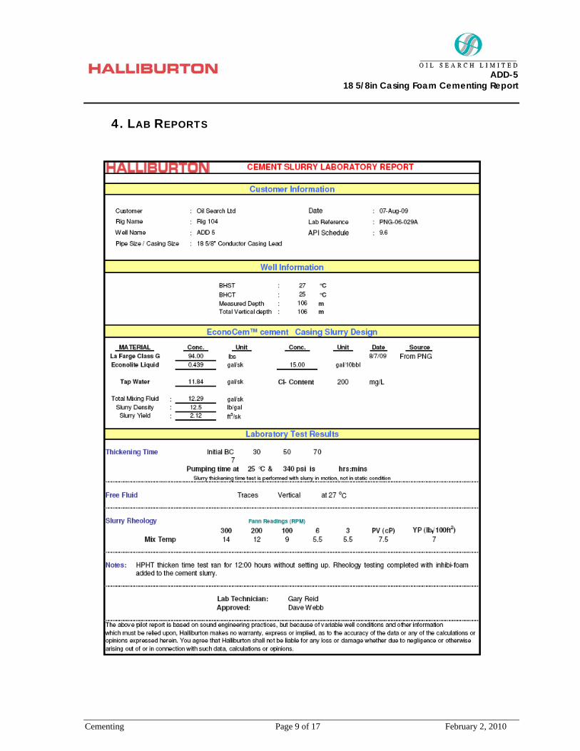
On the 17th of August 2009 foam job was commenced by mixing and pumping 119bbl of 12.5ppg lead slurry through the foam generator where the slurry was foamed to 7.5ppg and then lines were flushed with 5bbls of fresh water and the job was ended. On the 18th of August, due to the foam slurry being lost into a facture, the foam job was repeated. The annulus was filled with gravel and 220gal of FloChek was pumped followed by 24bbls of 12.5ppg lead slurry. The top up foam job was commenced by pumping 45bbl of 12.5ppg lead slurry through the foam generator where the slurry was foamed to 7.5ppg; few samples were collected and observed for the setting time. The base 12.5ppg slurry was set after a few hours but the foamed slurry samples did not set for a long time, because of the foaming agent used does not have foam stabilizer, bubbles generated are not uniform causing the slurry not to be stable.
Findings and Recommendations
1. What did we test in the lab?
The lab conducted thickening time tests on the base slurry, which was 12.5ppg slurry; as this slurry was of a light weight slurry and tested at low temperature, the slurry did not set up even after 12+hr which is normal for this kind of slurry.
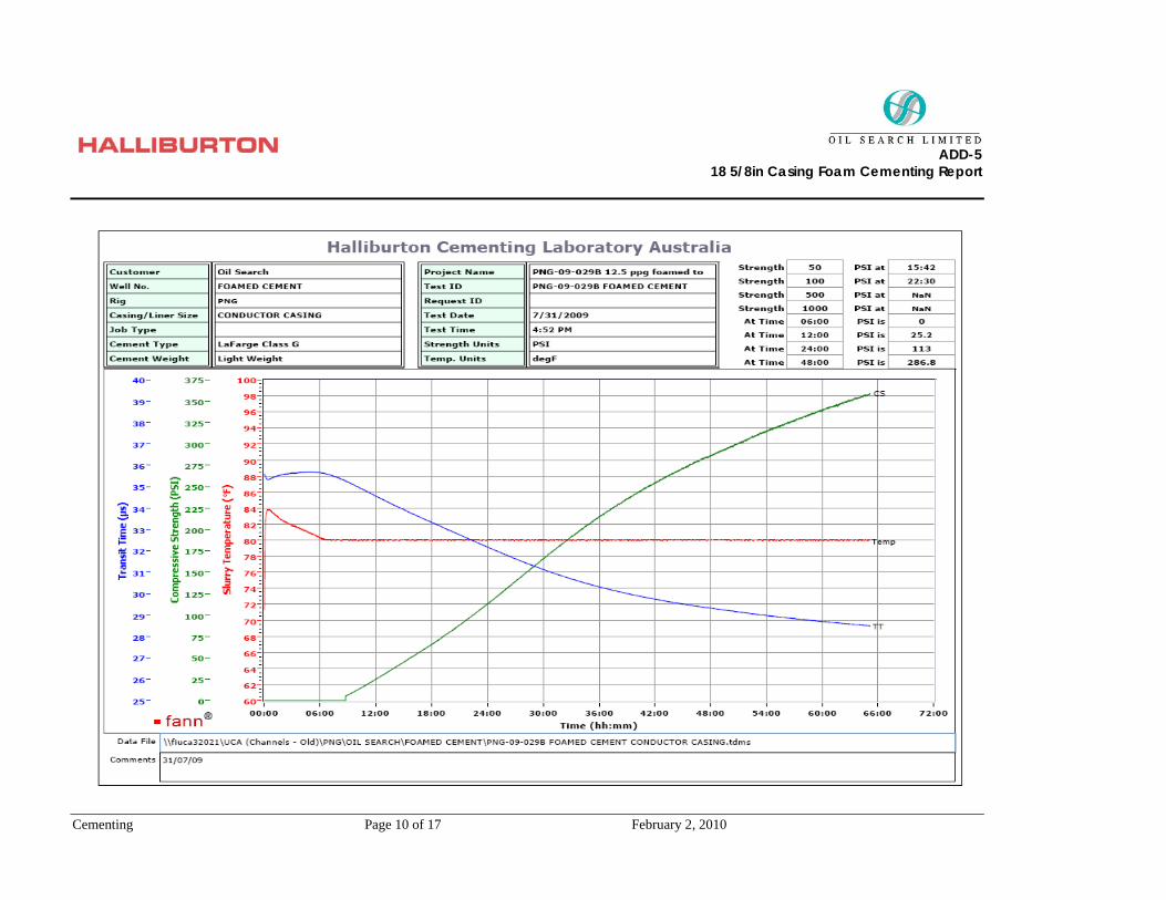
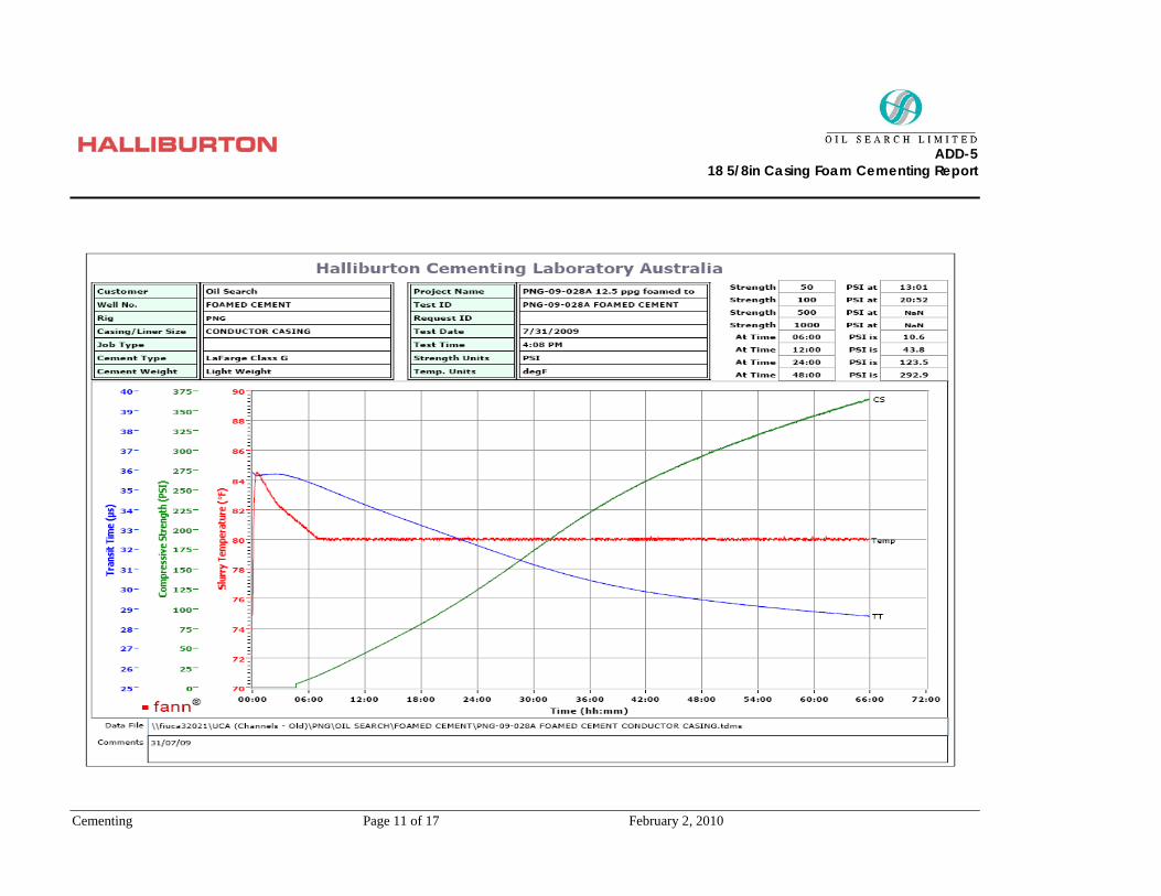
Two UCA tests were run, one for base slurry and same slurry with foaming agent. Both UCA are done at 12.5ppg one as a base slurry and one with foamer added (slowly mixed in but not foamed) to see the effect of the foamer as you cannot perform a UCA test on a foamed slurry, The foamed slurry itself was estimated to have a compression strength of 100psi after 24hr
If you observe the UCA graphs for both the base slurry and one with foamer added, 50psi is reached 13:01hr and 15:42hr respectively. This clearly shows adding foamer increasing the slurry setting time.
Base slurry with Foamer Base Slurry

ADD-5
18 5/8in Casing Foam Cementing Report
Cementing Page 3 of 17 February 2, 2010
Lab has sectioned 1 of the 2 slurry pipes prepared on Wednesday 22nd July afternoon. The foam slurry has set to some degree but is still very moist and brittle. Removing from the PVC pipe proved somewhat tricky as the cement was very crumbly please see below.
Lab techs left sections exposed to air to assist with the curing process over the weekend, pipe as a control (un-sectioned) and it was left to cure over the weekend (still inside the PVC pipe). Please see attached when they have been cut.
ADD-5
18 5/8in Casing Foam Cementing Report
Cementing Page 4 of 17 February 2, 2010
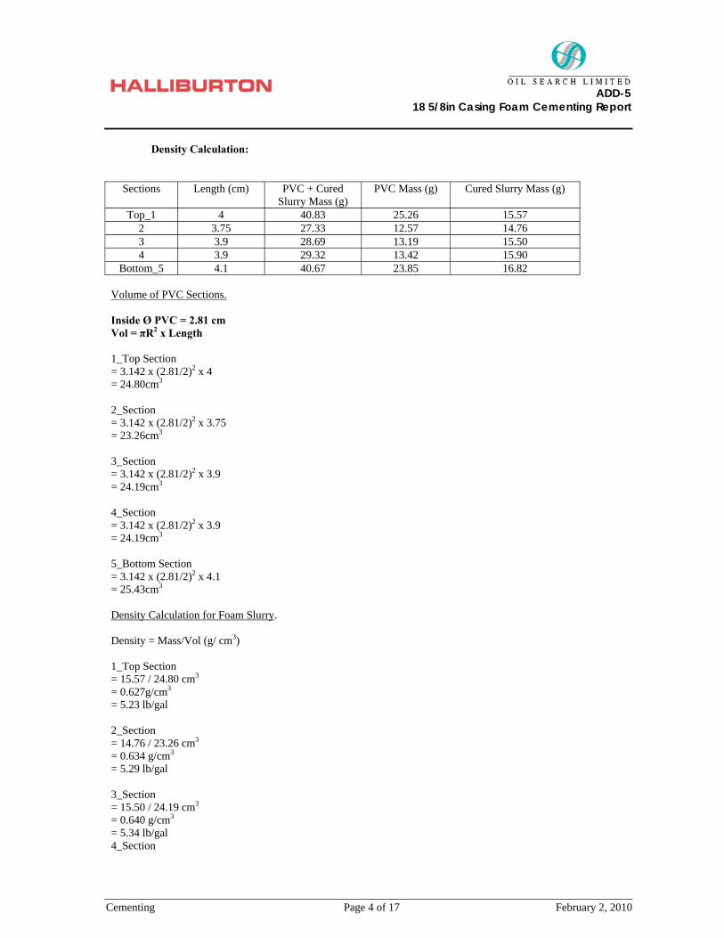
Density Calculation:
Sections Length (cm) PVC + Cured
Slurry Mass (g) PVC Mass (g) Cured Slurry Mass (g)
Top_1 4 40.83 25.26 15.57 2 3.75 27.33 12.57 14.76 3 3.9 28.69 13.19 15.50 4 3.9 29.32 13.42 15.90
Bottom_5 4.1 40.67 23.85 16.82 Volume of PVC Sections. Inside Ø PVC = 2.81 cm Vol = πR2 x Length 1_Top Section = 3.142 x (2.81/2)2 x 4 = 24.80cm3
2_Section = 3.142 x (2.81/2)2 x 3.75 = 23.26cm3
3_Section = 3.142 x (2.81/2)2 x 3.9 = 24.19cm3
4_Section = 3.142 x (2.81/2)2 x 3.9 = 24.19cm3
5_Bottom Section = 3.142 x (2.81/2)2 x 4.1 = 25.43cm3
Density Calculation for Foam Slurry. Density = Mass/Vol (g/ cm3) 1_Top Section = 15.57 / 24.80 cm3 = 0.627g/cm3 = 5.23 lb/gal 2_Section = 14.76 / 23.26 cm3 = 0.634 g/cm3 = 5.29 lb/gal 3_Section = 15.50 / 24.19 cm3 = 0.640 g/cm3 = 5.34 lb/gal 4_Section
ADD-5
18 5/8in Casing Foam Cementing Report
Cementing Page 5 of 17 February 2, 2010
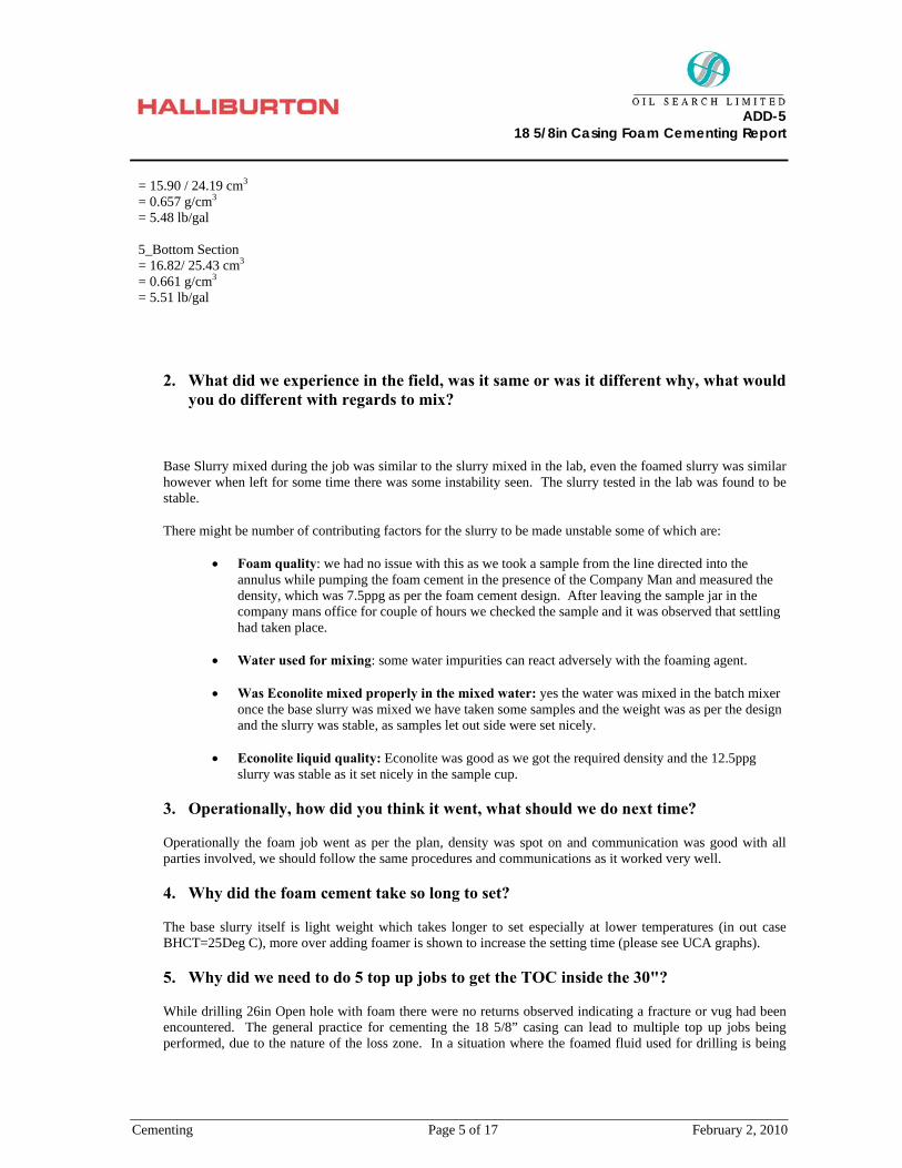
= 15.90 / 24.19 cm3 = 0.657 g/cm3 = 5.48 lb/gal 5_Bottom Section = 16.82/ 25.43 cm3 = 0.661 g/cm3 = 5.51 lb/gal
2. What did we experience in the field, was it same or was it different why, what would you do different with regards to mix?
Base Slurry mixed during the job was similar to the slurry mixed in the lab, even the foamed slurry was similar however when left for some time there was some instability seen. The slurry tested in the lab was found to be stable.
There might be number of contributing factors for the slurry to be made unstable some of which are:
• Foam quality: we had no issue with this as we took a sample from the line directed into the annulus while pumping the foam cement in the presence of the Company Man and measured the density, which was 7.5ppg as per the foam cement design. After leaving the sample jar in the company mans office for couple of hours we checked the sample and it was observed that settling had taken place.
• Water used for mixing: some water impurities can react adversely with the foaming agent.
• Was Econolite mixed properly in the mixed water: yes the water was mixed in the batch mixer
once the base slurry was mixed we have taken some samples and the weight was as per the design and the slurry was stable, as samples let out side were set nicely.
• Econolite liquid quality: Econolite was good as we got the required density and the 12.5ppg
slurry was stable as it set nicely in the sample cup.
3. Operationally, how did you think it went, what should we do next time?
Operationally the foam job went as per the plan, density was spot on and communication was good with all parties involved, we should follow the same procedures and communications as it worked very well.
4. Why did the foam cement take so long to set?
The base slurry itself is light weight which takes longer to set especially at lower temperatures (in out case BHCT=25Deg C), more over adding foamer is shown to increase the setting time (please see UCA graphs).
5. Why did we need to do 5 top up jobs to get the TOC inside the 30"?
While drilling 26in Open hole with foam there were no returns observed indicating a fracture or vug had been encountered. The general practice for cementing the 18 5/8” casing can lead to multiple top up jobs being performed, due to the nature of the loss zone. In a situation where the foamed fluid used for drilling is being
ADD-5
18 5/8in Casing Foam Cementing Report
Cementing Page 6 of 17 February 2, 2010
lost, a foamed or even lightened cement slurry with a long thickening time will not shut off a fracture unless it actually completely fills the fracture, which is very unusual.
Conclusion
Initially foam slurry was designed to only to fill a void not to cure losses in a natural fracture for which this foam slurry was not suitable.
Greater control when creating of foam slurries needs to be put in place, including the utilization of fit for purpose foaming agents. Also foaming a 15.8 ppg slurry down to say 11 ppg or 12 ppg will provide a faster setting slurry with better strength. A cap slurry to assist in holding in the foam would also stabilize the foam somewhat as it will add some hydrostatic pressure to the top of the foam column.
The application of the foam slurry depends on the nature of the formation integrity, if the formation fracture gradient is too weak to take the hydrostatic pressure from mud or standard cementing fluids, hence inducing a fracture, we could consider using foam slurries to reduce the hydrostatic pressure.
If the formation has natural fractures or vugs which can not even hold drilling foam, then the design needs to be changed for more reactive fluids such as a combination of 15.8ppg cement slurry with Econolite liquid and CaCl2. A thixotropic slurry may also be of some use. The use of gravel has also been employed in the past to great success.
Recommendations
In the future if Oil Search wants to run foam cement again, Halliburton recommend the following:
1. Better plan for the application of the foam slurry and do some long term planning for wells to allow the get the best possible design for a particular application as possible.
2. Foam a higher density slurry where possible.
3. Utilise a cap cement slurry.
4. Halliburton’s foaming agent called Zoneseal 3000 or 4000, which delivers stable foam.
5. Utilise more reactive treatments to cure losses in natural fracture or vug situations.
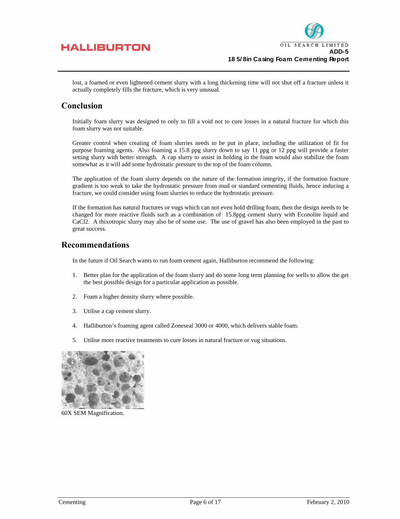
60X SEM Magnification.

ADD-5
18 5/8in Casing Foam Cementing Report
Cementing Page 7 of 17 February 2, 2010
2. FOAM JOB SCHEMATIC
Air vent
ADA Check Valve
#1 Check Valve
#1 Pressure transducer#2 Low Torc
#2 Check Valve #1 Low Torc
#2 Pressure Transducer
#3Low Torc
ADD-5 Well
Rig up Schematic for ADD-5 Air Foamed Cement Job
Air Compressor
Batch Mixer- Mix Water Tank
Cement Unit
Foamer injector
Bulk Cement pods
Foam Generator
4 way Cross
4 way Cross
ADD-5
18 5/8in Casing Foam Cementing Report
Cementing Page 8 of 17 February 2, 2010
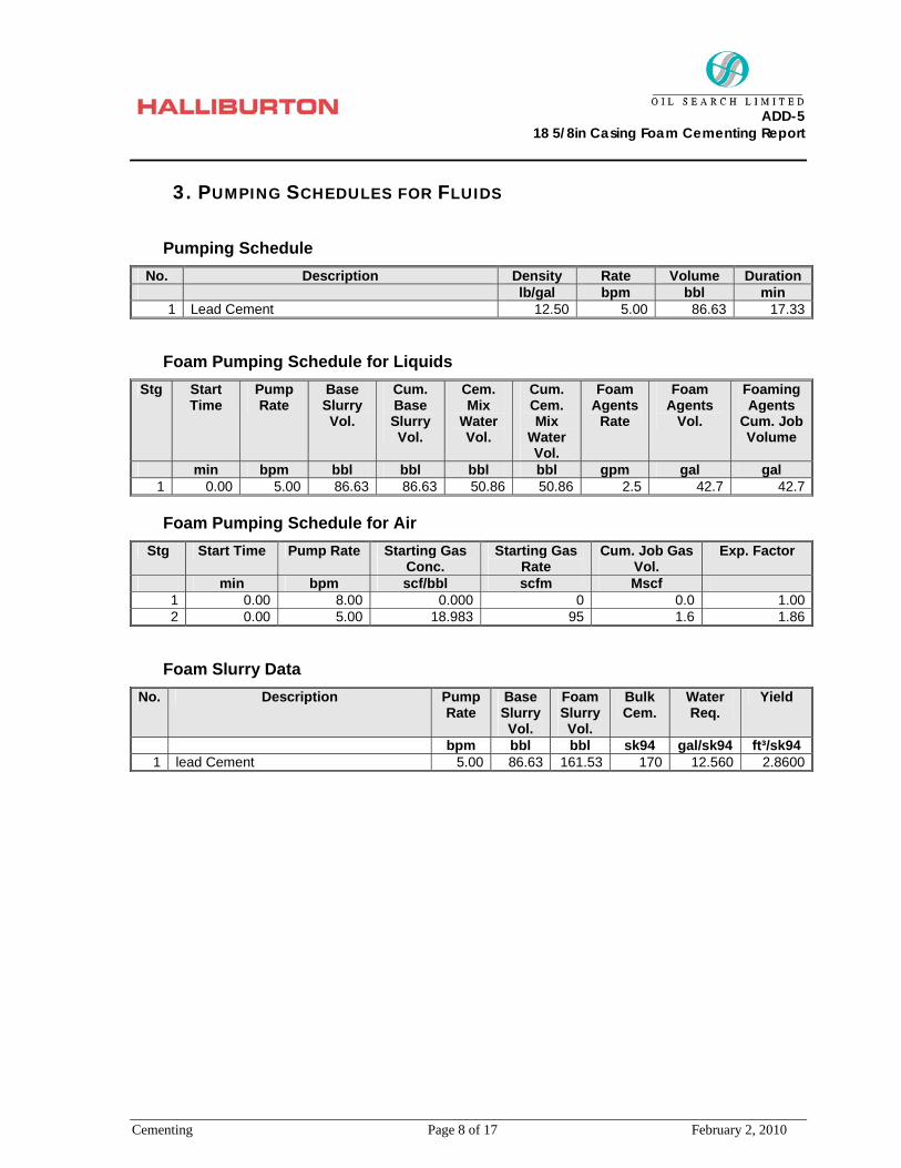
3. PUMPING SCHEDULES FOR FLUIDS
Pumping Schedule No. Description Density Rate Volume Duration
lb/gal bpm bbl min 1 Lead Cement 12.50 5.00 86.63 17.33
Foam Pumping Schedule for Liquids Stg Start
Time Pump Rate
Base Slurry Vol.
Cum. Base Slurry Vol.
Cem. Mix
Water Vol.
Cum. Cem. Mix
Water Vol.
Foam Agents
Rate
Foam Agents
Vol.
Foaming Agents
Cum. Job Volume
min bpm bbl bbl bbl bbl gpm gal gal 1 0.00 5.00 86.63 86.63 50.86 50.86 2.5 42.7 42.7
Foam Pumping Schedule for Air Stg Start Time Pump Rate Starting Gas
Conc. Starting Gas
Rate Cum. Job Gas
Vol. Exp. Factor
min bpm scf/bbl scfm Mscf 1 0.00 8.00 0.000 0 0.0 1.002 0.00 5.00 18.983 95 1.6 1.86
Foam Slurry Data No. Description Pump
Rate Base Slurry Vol.
Foam Slurry Vol.
Bulk Cem.
Water Req.
Yield
bpm bbl bbl sk94 gal/sk94 ft³/sk94 1 lead Cement 5.00 86.63 161.53 170 12.560 2.8600
ADD-5
18 5/8in Casing Foam Cementing Report
Cementing Page 9 of 17 February 2, 2010
4. LAB REPORTS
ADD-5
18 5/8in Casing Foam Cementing Report
Cementing Page 10 of 17 February 2, 2010
ADD-5
18 5/8in Casing Foam Cementing Report
Cementing Page 11 of 17 February 2, 2010
ADD-5
18 5/8in Casing Foam Cementing Report
Cementing Page 12 of 17 February 2, 2010
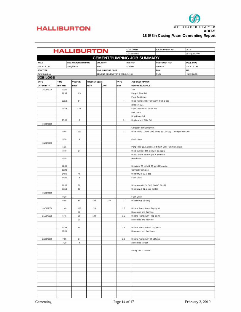
5. JOB LOGS
CEMENT CONDUCTOR CASING 14161Prepared for G.Harms
16/08/2009
Prepared by D.White
Oil Search LtdPOST JOB REPORTS
CEMENTING/PUMPING
Well Name : ADD #5
Rig: HAES Rig 104
The Future is Working Together.
Notice: Although the information contained in this report is based on sound engineering practices, the copyright owner(s) does (do) not accept any responsibility whatsoever, in negligence or otherwise, for any loss or damage
arising from the use of the information given in this report

ADD-5
18 5/8in Casing Foam Cementing Report
Cementing Page 13 of 17 February 2, 2010
hrs hrs hrs hrs
12 12 12 12
12 0 0 0
NEW CASING OPEN HOLE + EXCESS OR CALIPER DATA PREVIOUS CASINGS
Non Tapered Liner , Conventional, 24m shoe track
18 5/8in ppf Vam-Top : 0m to 103m MD, 103m TVD 26in, 100 percent excess, 0m to 103m 7"in, ppf, to m
Concentration
MIX FLUIDYIELD 0.00cuft/ft
0
DENSITY 0.0ppg WATER 0.00gal/sk
0.00gal/sk
WATER SOURCE
CEMENT TYPE at lb/sk
Total Cement Used MT
Estimated TOC m
Total Used
Gascon-469 7.5 gal/10bbl 25
7SCR-100L 2 gal/10bbl
Halad-413L 47.5
Halad-344 3 gal/10bbl
0
WATER SOURCE Freshwater
CEMENT TYPE ABC Class 'G' at 94lb/sk
DENSITY
MIX FLUID 5.15gal/skYIELD
15.8ppg
CFR-3L 3 gal/10bbl 10
Total Cement Used 178sks
WATER
1.16cuft/ft
4.79gal/sk
10
Estimated TOC 2200m
Additive
13.5 gal/10bbl
Calcium Chloride 2 %BWOC 18sks
2.12cuft/ft MIX FLUID
CEMENT TYPE ABC Class 'G' at 94lb/sk
12.29gal/sk
WATER SOURCE
YIELD
DENSITY 12.5ppg WATER 12.29gal/sk
Estimated TOC 0m
Total Cement Used 1059sks
0 0#N/A 18 5/8 Float Shoe
FLOAT EQUIPMENT AND CASING EQUIPMENTSAP# FLOAT EQUIPMENT QTY SAP# PLUGS QTY
Batch mixer 120
OTHER EQUIPMENT HOURS
10886800 LAS311 - DUAL CAB TOYOTA HILUX PICKUP 24 #N/A Air Compressor 10978676 12
SAP# VEHICLES / TRAILERS
12 #N/A
HOURS SAP# BULK SUPPLY / TANKS
Prem
EQUIPMENTSAP# PUMPING / MIXING HOURS
WELL LOCATION/FIELD NAME
16 August 2009
CUSTOMER REP WELL TYPE
CEMENT/PUMPING JOB SUMMARYCOUNTRY HES REP
Oil Search Ltd 0
Additive Concentration Total Used AdditiveTotal UsedConcentration
Single
WELL PROFILE
CEMENT DESIGNS
0 #N/A
1
HOURS SAP#
P Tank 10885488 12
#N/A HT-400 PSY 10084542 12 #N/A P Tank 10885487 12
#N/A HT-400 PSY 10147059
00127111
HAES Rig 104
JOB TYPE JOB PURPOSE CODE BDA
PERSONNEL / EXPOSURE
00453707 215744Ronald Zwarteveen
PERSONNEL / EXPOSURE PERSONNEL / EXPOSURE PERSONNEL / EXPOSURE
Russell William00393741 #N/A
PNG D.White G.Harms Gas & Oil Dev
CUSTOMER SALES ORDER No.
END OF JOB DETAILS
Darcey White
John Tumbiago Arabe 0 0 0
PERSONELL
ADD #5 S.Highlands
DATE
RIG
Zonal Isolation CEMENT CONDUCTOR CASING 14161 Perth
ADD-5
18 5/8in Casing Foam Cementing Report
Cementing Page 14 of 17 February 2, 2010
JOB LOGSZonal Isolation CEMENT CONDUCTOR CASING 14161 Perth HAES Rig 104
G.Harms Gas & Oil Dev
JOB TYPE
Gas & Oil Dev S.Highlands PNG D.White
16 August 2009
CUSTOMER REP WELL TYPE
JOB PURPOSE CODE BDA RIG
CEMENT/PUMPING JOB SUMMARY
CUSTOMER SALES ORDER No. DATE
Oil Search Ltd 0
WELL LOCATION/FIELD NAME COUNTRY HES REP
Finally cmt to surface
14 2.5 Mix and Pump slurry @ 12.5ppg
Disconnect to flush7:18 4
22/08/2009 7:05
2.5
11:05 Disconnect and flush lines
Mix and Pump Slurry - Top up #3
Disconnect and flush line10
10:45 45
21/08/2009 6:45 35 100 2.5
108 110
Mix and Pump slurry- Top up #2
2.5 Mix and Pump Slurry- Top up #1
Disconnect and flush line10
20/08/2009 1:40
0:05 50 400 270 3 Mix Slir ry @ 12.5ppg
Flush Lines
Mix slurry @ 12.5 ppg 53 bbl53
0:20
23:50
19/08/2009
22:00 50
3
Mix water with 2% CaCl BWOC 50 bbl
Flush Lines
Mix slurry @ 12.5 ppg4514:00
14:20
Connect Foam Gen13:40
12:30 Mix Water 50 bbl with 75 gal of Econol ite
Mixwtr 20 bbl with 40 gall of Econolite
flush Lines4:20
3:40 24 Mix & pump 24 bbl slurry @ 12.5 ppg
18/08/2009
1:15
Flush Lines
Pump 220 gal. Econolite with With 5 bbl FW into Annulus
4:45 119
5:30 3
3 Mix & Pump 119 bbl Lead Slurry @ 12.5 ppg Through Foam Gen
17/08/2009
Coneect Foam Equipment
Drop Foam Ball
23:30 5 Displace wi th 5 bbl FW
32 bbl mixwtr.
Pull 1 joint
Flush Lines with 1.75 bbl FW
1.5
45422:50
DAY-MTH-YR HRS:MIN
22:35
16/08/2009 22:00
DATE TIME VOLUME PRESSURE (psi)
JSA
BBLS HIGH
RATE JOB DESCRIPTION
LOW BPM REMARKS/DETAILS
3
Pump 1,5 bbl FW
Press Test Lines
Mix & Pump 54 bbl Tail Slurry @ 15.8 ppg
23:18 1.75

ADD-5
18 5/8in Casing Foam Cementing Report
Cementing Page 15 of 17 February 2, 2010
TYPE OF JOB (Cementing or Non-Cementing):Select the job type (Cementing or Non-Cementing)
TOTAL OPERATING TIME (hrs)Rig up/ Pumping/ Rig Down
This should be recordable incidents only
WAS THE JOB PURPOSE ACHIEVED?This will be dictated by the customer
TOTAL TIME PUMPING (hrs)Total number of hours pumping fluid on this job
NON -PRODUCTIVE RIG TIME:As a result of Halliburton cementing PSL
NUMBER OF JSA'S PERFORMED:
NUMBER OF UNPLANNED SHUTDOWNS (After starting to pump)
TYPE OF RIG(CLASSIFICATION) JOB WAS PERFORMED ON:
WAS THIS A PRIMARY CEMENT JOB (YES / NO)Primary cement job = Casing job, Liner Job, tie back DID WE RUN WIPER PLUGS?
WAS THIS A PLUG OR SQUEEZE JOB?
WAS THIS A PRIMARY OR REMEDIAL JOB?Remedial = Repeated attempts or corrections of initial cement job
MIXING DENSITY OF JOB STAYED IN DESIGNED RANGEDensity defined as +/- 0.2ppg. Calculation: Total bbls cement mixed at designed density divided by total bbls of cement multiplied by 100
WAS AUTOMATED DENSITY CONTROL USED
JOB WAS PUMPED AT DESIGNED PUMP RATEPump rate ranged defined as +/- bpm. Calculation : total bbls of fluid pumped at the designed rate divided by total bbls of fluid pumped multiplied by 100
NUMBER OF REMEDIAL SQUEEZE JOBS REQUIRED - HESNumber of remedial squeeze jobs required after primary job performed by HES
NUMBER OF REMEDIAL AQUEEZE JOBS REQUIRED - COMPETITIONNumber of remedial squeeze jobs required after primary job performed by competition
NUMBER OF REMEDIAL PLUG JOBS REQUIRED - HESNumber of remedial plug jobs required after primary plug pumped by HES
ANY REASON FOR UNPLANNED SHUTDOWNS (After starting to pump)Add details in job logs
Add details in job logs
KEY PERFORMANCE INDICATORS
Remedial
None
Cementing
HSE INCIDENT, ACCIDENT, INJURY:
Neither
YES
12.0 hrs
NO
0
0.0 hrs
12.0 hrs
YES
LAND
1
ANY REASON FOR NON-PRODUCTIVE RIG TIME (Cementing P
0
100%
NO
Yes
0
0

ADD-5
18 5/8in Casing Foam Cementing Report
Cementing Page 16 of 17 February 2, 2010
ADD 5 - Conductor Job #2
17/08/200904:20 04:40 05:00 05:20 05:40
17/08/200906:00
Time
8
10
12
14
16
18
20
A
1000
2000
3000
4000
5000
B
1
2
3
4
5
6
7
8
9
C
25
50
75
100
125
D
Recirc Density (lb/gal) DHole Density (lb/gal)PS Pressure (psi) DS Pressure (psi)Cmb Rate (bpm) CmbTotal (bbl)
A AB BC D
TG Version G3.4.120-Aug-09 15:14
ADD-5
18 5/8in Casing Foam Cementing Report
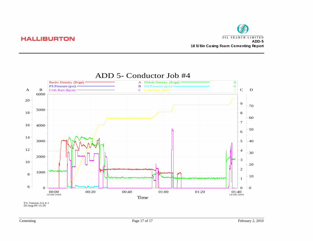
Cementing Page 17 of 17 February 2, 2010
ADD 5- Conductor Job #4
19/08/200900:00 00:20 00:40 01:00 01:20
19/08/200901:40
Time
6
8
10
12
14
16
18
20
A
0
1000
2000
3000
4000
5000
6000B
0
1
2
3
4
5
6
7
8
9
C
0
10
20
30
40
50
60
70
D
Recirc Density (lb/gal) DHole Density (lb/gal)PS Pressure (psi) DS Pressure (psi)Cmb Rate (bpm) CmbTotal (bbl)
A AB BC D
TG Version G3.4.120-Aug-09 15:20
Related Documents