Adaptive Zone-1 Setting Following Structural and Operational Changes in Power System Subhadeep Paladhi, Student Member, IEEE and Ashok Kumar Pradhan, Senior Member, IEEE Abstract—Change in network structure or operating condition in a power system affects the impedance as calculated by distance relay during fault. Such changes may lead to malfunction of distance relay at times. In this paper, an adaptive distance relay setting method using local data is proposed to prevent zone-1 malfunction following structural and operational changes. The performance of proposed adaptive setting method is tested on 39-bus New England system and a generic 12-bus power system using PSCAD/EMTDC simulation data and a comparative assessment is also provided. Index Terms—Distance Relay, Adaptive Relaying, Numerical Protection, Structural Change, Power System Faults I. I NTRODUCTION R EPORTS on recent blackouts ask for revamping existing schemes for transmission network protection [1]–[3]. Distance relaying is the common method for both primary and backup protection of transmission lines. Though a distance relay is set to protect a line for all types of fault, a large scale disturbance, like segregation of network, line tripping and bulk load/generation switching etc. affects relay operation and leads to its malfunction at times [4]–[7]. Power swing and load encroachment are considered as important issues leading to distance relay malfunction during such changes. To avoid unwanted line tripping during such situations, dif- ferent blocking techniques are available for distance relaying [8]–[12]. The vulnerable points in a power system network prone to relay maloperation during such situations can be identified using different strategies such as system integrity protection scheme (SIPS), reachability analysis, superimposed technique, breakpoint determination etc. [4]–[7], [12]–[17]. These methods use wide area measurement system (WAMS) data with information of network topology. Such WAMS based approaches have been proposed for improvement in performance of zone-2 and zone-3, but not suitable to zone-1 due to latency issue. The occurrence of any structural and operational changes in an interconnected power system modulates the voltage and power and results in change of the seen impedance of a distance relay significantly, particularly for high resistance faults [7], [16]–[20]. To compensate the effect of fault re- sistance in the presence of remote infeed, adaptive distance relay setting schemes have been proposed [20]–[25]. A zero sequence component based adaptive mho relay setting has The work is supported in part by the Department of Science and Tech- nology, New Delhi, India, under Grant DST/RCUK/SEGES/2012/02(G). The authors are with the Department of Electrical Engineering, Indian Institute of Technology, Kharagpur 721302, India (e-mail: paladhisubha [email protected]; [email protected]). been presented in [20]. The method is accurate in handling fault resistance but neglects the system impedances on both sides of the protected line. An adaptive distance protection is proposed in [21] calculating the voltage drop between relaying point and fault point considering fault resistance. An adaptive impedance relay based on composite polarizing voltage has been presented in [22], along with a blocking scheme to accommodate the inphase problem associated with high resistance faults. An adaptive setting method based on sequence components has been presented in [23]. A phase coordinate based fault resistance estimation scheme has been used for the distance relaying scheme in [24]. An adaptive mho relay setting using fault and prefault voltages as polarized quantities is proposed in [25]. These approaches consider the equivalent systems on both sides of protected line to remain constant, which may not be correct for a dynamic power system. The distance relay setting approaches presented in [18], [19] compensate the effect of high fault resistance under different loading conditions using artificial neural network approach which requires large number of training data. To obtain sufficient training sets for real power systems is dif- ficult. Some of the available distance relays apply different relay setting techniques for protecting transmission lines for different source impedance ratio (SIR) situations [26]–[35]. Such relays with multiple settings for different SIRs cannot change the settings instantaneously under dynamic system conditions which is a requirement for zone-1 protection. These methods with predefined settings for different SIRs do not provide enough flexibility particularly for high resistance fault detection. In this work an adaptive relay setting scheme is proposed to prevent zone-1 malfunction following structural or operational change in a power system. Proposed scheme uses a fixed zone- 1 setting followed by an adaptive setting with a delay of 2 cycles following a fault detection. This will avoid unintentional operation of the backup protection for a zone-1 fault during such a changed situation. The parameters required for the adaptive setting are calculated using local data available to the relay. Proposed scheme is tested using PSCAD/EMTDC simulation data for 39-bus New England system and a generic 12-bus power system. Comparative assessment shows the strength of the method. II. I SSUES ON DISTANCE RELAY FOLLOWING STRUCTURAL AND OPERATIONAL CHANGES Figure 1 shows a transmission network protected by stepped distance relaying scheme, where zone-1 covers up to 80% of This is a peer-reviewed, accepted author manuscript of the following article: Paladhi, S., & Pradhan, A. K. (2018). Adaptive zone-1 setting following structural and operational changes in power system. IEEE Transactions on Power Delivery, 33(2), 560-569. https://doi.org/10.1109/TPWRD.2017.2728682

Welcome message from author
This document is posted to help you gain knowledge. Please leave a comment to let me know what you think about it! Share it to your friends and learn new things together.
Transcript
Adaptive Zone-1 Setting Following Structuraland Operational Changes in Power SystemSubhadeep Paladhi, Student Member, IEEE and Ashok Kumar Pradhan, Senior Member, IEEE
Abstract—Change in network structure or operating conditionin a power system affects the impedance as calculated by distancerelay during fault. Such changes may lead to malfunction ofdistance relay at times. In this paper, an adaptive distancerelay setting method using local data is proposed to preventzone-1 malfunction following structural and operational changes.The performance of proposed adaptive setting method is testedon 39-bus New England system and a generic 12-bus powersystem using PSCAD/EMTDC simulation data and a comparativeassessment is also provided.
Index Terms—Distance Relay, Adaptive Relaying, NumericalProtection, Structural Change, Power System Faults
I. INTRODUCTION
REPORTS on recent blackouts ask for revamping existingschemes for transmission network protection [1]–[3].
Distance relaying is the common method for both primary andbackup protection of transmission lines. Though a distancerelay is set to protect a line for all types of fault, a largescale disturbance, like segregation of network, line trippingand bulk load/generation switching etc. affects relay operationand leads to its malfunction at times [4]–[7]. Power swingand load encroachment are considered as important issuesleading to distance relay malfunction during such changes.To avoid unwanted line tripping during such situations, dif-ferent blocking techniques are available for distance relaying[8]–[12]. The vulnerable points in a power system networkprone to relay maloperation during such situations can beidentified using different strategies such as system integrityprotection scheme (SIPS), reachability analysis, superimposedtechnique, breakpoint determination etc. [4]–[7], [12]–[17].These methods use wide area measurement system (WAMS)data with information of network topology. Such WAMSbased approaches have been proposed for improvement inperformance of zone-2 and zone-3, but not suitable to zone-1due to latency issue.
The occurrence of any structural and operational changesin an interconnected power system modulates the voltageand power and results in change of the seen impedance ofa distance relay significantly, particularly for high resistancefaults [7], [16]–[20]. To compensate the effect of fault re-sistance in the presence of remote infeed, adaptive distancerelay setting schemes have been proposed [20]–[25]. A zerosequence component based adaptive mho relay setting has
The work is supported in part by the Department of Science and Tech-nology, New Delhi, India, under Grant DST/RCUK/SEGES/2012/02(G). Theauthors are with the Department of Electrical Engineering, Indian Institute ofTechnology, Kharagpur 721302, India (e-mail: paladhisubha [email protected];[email protected]).
been presented in [20]. The method is accurate in handlingfault resistance but neglects the system impedances on bothsides of the protected line. An adaptive distance protectionis proposed in [21] calculating the voltage drop betweenrelaying point and fault point considering fault resistance.An adaptive impedance relay based on composite polarizingvoltage has been presented in [22], along with a blockingscheme to accommodate the inphase problem associated withhigh resistance faults. An adaptive setting method based onsequence components has been presented in [23]. A phasecoordinate based fault resistance estimation scheme has beenused for the distance relaying scheme in [24]. An adaptivemho relay setting using fault and prefault voltages as polarizedquantities is proposed in [25]. These approaches consider theequivalent systems on both sides of protected line to remainconstant, which may not be correct for a dynamic powersystem. The distance relay setting approaches presented in[18], [19] compensate the effect of high fault resistance underdifferent loading conditions using artificial neural networkapproach which requires large number of training data. Toobtain sufficient training sets for real power systems is dif-ficult. Some of the available distance relays apply differentrelay setting techniques for protecting transmission lines fordifferent source impedance ratio (SIR) situations [26]–[35].Such relays with multiple settings for different SIRs cannotchange the settings instantaneously under dynamic systemconditions which is a requirement for zone-1 protection. Thesemethods with predefined settings for different SIRs do notprovide enough flexibility particularly for high resistance faultdetection.
In this work an adaptive relay setting scheme is proposed toprevent zone-1 malfunction following structural or operationalchange in a power system. Proposed scheme uses a fixed zone-1 setting followed by an adaptive setting with a delay of 2cycles following a fault detection. This will avoid unintentionaloperation of the backup protection for a zone-1 fault duringsuch a changed situation. The parameters required for theadaptive setting are calculated using local data available tothe relay. Proposed scheme is tested using PSCAD/EMTDCsimulation data for 39-bus New England system and a generic12-bus power system. Comparative assessment shows thestrength of the method.
II. ISSUES ON DISTANCE RELAY FOLLOWINGSTRUCTURAL AND OPERATIONAL CHANGES
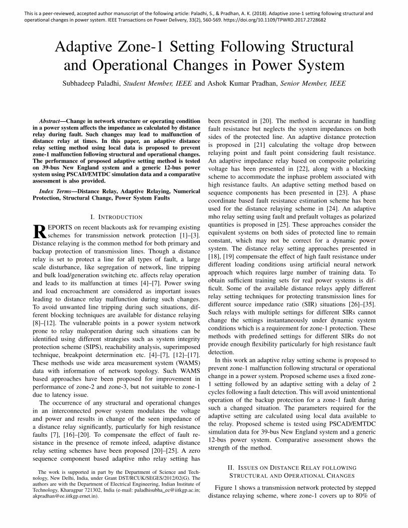
Figure 1 shows a transmission network protected by steppeddistance relaying scheme, where zone-1 covers up to 80% of
This is a peer-reviewed, accepted author manuscript of the following article: Paladhi, S., & Pradhan, A. K. (2018). Adaptive zone-1 setting following structural and operational changes in power system. IEEE Transactions on Power Delivery, 33(2), 560-569. https://doi.org/10.1109/TPWRD.2017.2728682
the line section and zone-2 up to 50% of the shortest linesection connected to the remote bus. The equivalent systemson the relay and the remote ends of transmission line in aninterconnected power system are termed as local grid andremote grid respectively. The two grids consist of several sub-systems interconnected with each other as shown in Fig. 1.The distance relays in the protection scheme are consideredwith quadrilateral characteristics to cover fault resistance upto 100 Ω.
M N
FRM RN
RP
Zone-1 reachZone-2 reach
Sub-system 6
Sub-system 4
Sub-system 5
Sub-system 3
Sub-system 2
Sub-system 1
Relay associated with circuit breaker
LM
2
1
3 4
5
67
Fig. 1. Transmission system protected by stepped distance scheme
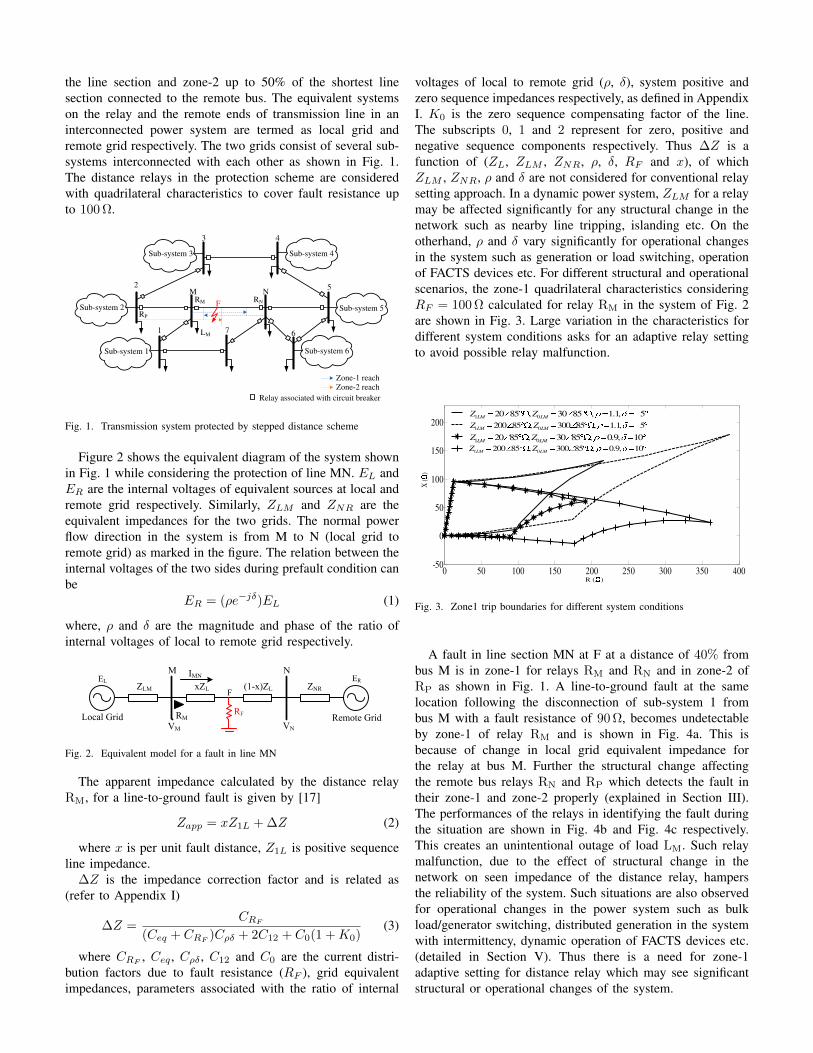
Figure 2 shows the equivalent diagram of the system shownin Fig. 1 while considering the protection of line MN. EL andER are the internal voltages of equivalent sources at local andremote grid respectively. Similarly, ZLM and ZNR are theequivalent impedances for the two grids. The normal powerflow direction in the system is from M to N (local grid toremote grid) as marked in the figure. The relation between theinternal voltages of the two sides during prefault condition canbe
ER = (ρe−jδ)EL (1)
where, ρ and δ are the magnitude and phase of the ratio ofinternal voltages of local to remote grid respectively.
EL ER
ZLM xZL (1-x)ZL ZNR
Local Grid Remote GridRM
VM VN
RF
M N
F
IMN
Fig. 2. Equivalent model for a fault in line MN
The apparent impedance calculated by the distance relayRM, for a line-to-ground fault is given by [17]
Zapp = xZ1L + ∆Z (2)
where x is per unit fault distance, Z1L is positive sequenceline impedance.
∆Z is the impedance correction factor and is related as(refer to Appendix I)
∆Z =CRF
(Ceq + CRF)Cρδ + 2C12 + C0(1 +K0)
(3)
where CRF, Ceq , Cρδ , C12 and C0 are the current distri-
bution factors due to fault resistance (RF ), grid equivalentimpedances, parameters associated with the ratio of internal
voltages of local to remote grid (ρ, δ), system positive andzero sequence impedances respectively, as defined in AppendixI. K0 is the zero sequence compensating factor of the line.The subscripts 0, 1 and 2 represent for zero, positive andnegative sequence components respectively. Thus ∆Z is afunction of (ZL, ZLM , ZNR, ρ, δ, RF and x), of whichZLM , ZNR, ρ and δ are not considered for conventional relaysetting approach. In a dynamic power system, ZLM for a relaymay be affected significantly for any structural change in thenetwork such as nearby line tripping, islanding etc. On theotherhand, ρ and δ vary significantly for operational changesin the system such as generation or load switching, operationof FACTS devices etc. For different structural and operationalscenarios, the zone-1 quadrilateral characteristics consideringRF = 100 Ω calculated for relay RM in the system of Fig. 2are shown in Fig. 3. Large variation in the characteristics fordifferent system conditions asks for an adaptive relay settingto avoid possible relay malfunction.
R ()
X (
)
0 50 100 150 200 250 300 350 400-50
0
50
100
150
200
1 020 85 , 30 85 , 0.9, 10
LM LMZ Z
1 0200 85 , 300 85 , 0.9, 10
LM LMZ Z
1 0200 85 , 300 85 , 1.1, 5
LM LMZ Z
1 020 85 , 30 85 , 1.1, 5
LM LMZ Z
Fig. 3. Zone1 trip boundaries for different system conditions
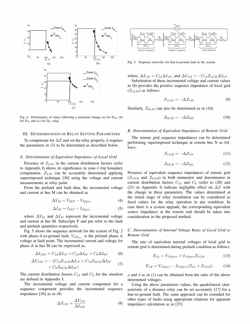
A fault in line section MN at F at a distance of 40% frombus M is in zone-1 for relays RM and RN and in zone-2 ofRP as shown in Fig. 1. A line-to-ground fault at the samelocation following the disconnection of sub-system 1 frombus M with a fault resistance of 90 Ω, becomes undetectableby zone-1 of relay RM and is shown in Fig. 4a. This isbecause of change in local grid equivalent impedance forthe relay at bus M. Further the structural change affectingthe remote bus relays RN and RP which detects the fault intheir zone-1 and zone-2 properly (explained in Section III).The performances of the relays in identifying the fault duringthe situation are shown in Fig. 4b and Fig. 4c respectively.This creates an unintentional outage of load LM. Such relaymalfunction, due to the effect of structural change in thenetwork on seen impedance of the distance relay, hampersthe reliability of the system. Such situations are also observedfor operational changes in the power system such as bulkload/generator switching, distributed generation in the systemwith intermittency, dynamic operation of FACTS devices etc.(detailed in Section V). Thus there is a need for zone-1adaptive setting for distance relay which may see significantstructural or operational changes of the system.
0 50 100 150 200-10
0
10
20
30
40
0 50 100 150 2000
5
10
15
20
25
30
35
Zone-1R
N
Zapp
RN
Zone-1R
M
Zapp
RM
(b)(a)
0 50 100 150 2000
10
20
30
40
50
Zone-1R
P
Zone-2R
P
Zapp
RP
(c)
Fig. 4. Performance of relays following a structural change (a) for RM, (b)for RN and (c) for RP relay
III. DETERMINATION OF RELAY SETTING PARAMETERS
To compensate for ∆Z and set the relay properly, it requiresthe parameters in (3) to be determined as described below.
A. Determination of Equivalent Impedance of Local Grid
Presence of ZLM in the current distribution factors (referto Appendix I) shows its significance in zone-1 trip boundarycomputation. ZLM can be accurately determined applyingsuperimposed technique [36] using the voltage and currentmeasurements at relay point.
From the prefault and fault data, the incremental voltageand current at bus M can be obtained as
∆VM = VMF − VMpre (4)
∆IM = IMF − IMpre (5)
where ∆VM and ∆IM represent the incremental voltageand current at bus M. Subscripts F and pre refer to the faultand prefault quantities respectively.
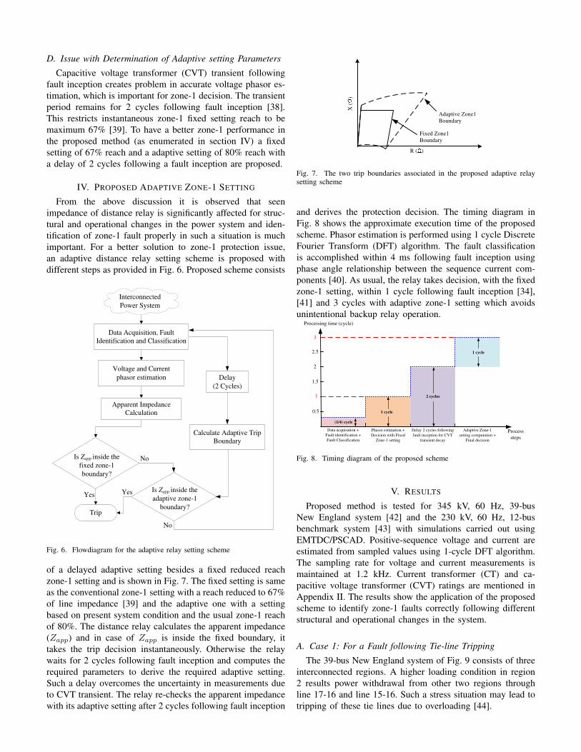
Fig. 5 shows the sequence network for the system of Fig. 2with phase-A-to-ground fault. VAFpre is the prefault phase Avoltage at fault point. The incremental current and voltage forphase-A at bus M can be expressed as,
∆IAM = C12∆I1F + C12∆I2F + C0∆I0F (6)
∆VAM = − (C12Z1LM∆I1F + C12Z2LM∆I2F
+ C0Z0LM∆I0F )(7)
The current distribution factors C12 and C0 for the situationare defined in Appendix I.
The incremental voltage and current component for asequence component provides the incremental sequenceimpedance [36] as in (8).
∆Z1M =∆V1M∆I1M
(8)
VAFpre+ -
Z1NR (1-x)Z1L
Z1LM xZ1L
∆V1F
∆I1F RF
Z2NR (1-x)Z2L
Z2LM xZ2L
∆V2F
∆I2F RF
Z0NR (1-x)Z0L
Z0LM xZ0L
∆V0F
∆I0F RF
Positive sequence Negative sequence Zero sequence
Fig. 5. Sequence networks for line-to-ground fault in the system
where, ∆I1M = C12∆I1F , and ∆V1M = −C12Z1LM∆I1F .Substitution of these incremental voltage and current values
in (8) provides the positive sequence impedance of local grid(Z1LM ) as follows:
Z1LM = −∆Z1M (9)
Similarly, Z0LM can also be determined as in (10).
Z0LM = −∆Z0M (10)
B. Determination of Equivalent Impedance of Remote Grid
The remote grid sequence impedances can be determinedperforming superimposed technique at remote bus N as fol-lows:
Z1NR = −∆Z1N (11)
Z0NR = −∆Z0N (12)
Presence of equivalent sequence impedances of remote grid(Z1NR and Z0NR) in both numerator and denominator incurrent distribution factors C12 and C0 (refer to (20) and(21) in Appendix I) indicate negligible effect on ∆Z withthe change in these parameters. The values determined atthe initial stage of relay installation can be considered asfixed values for the relay operation in any condition. Incase there is a system upgrade, the corresponding equivalentsource impedance at the remote end should be taken intoconsideration in the proposed method.
C. Determination of Internal Voltage Ratio of Local Grid toRemote Grid
The raio of equivalent internal voltages of local grid toremote grid is determined during prefault condition as follows:
E1L = V1Mpre + I1MpreZ1LM (13)
E1R = V1Mpre − I1Mpre(Z1L + Z1NR) (14)
ρ and δ as in (1) can be obtained from the ratio of the abovedetermined voltages.
Using the above parameters values, the quadrilateral char-acteristic of a distance relay can be set accurately [17] for aline-to-ground fault. The same approach can be extended forother types of faults using appropriate relations for apparentimpedance calculation as in [37].
D. Issue with Determination of Adaptive setting Parameters
Capacitive voltage transformer (CVT) transient followingfault inception creates problem in accurate voltage phasor es-timation, which is important for zone-1 decision. The transientperiod remains for 2 cycles following fault inception [38].This restricts instantaneous zone-1 fixed setting reach to bemaximum 67% [39]. To have a better zone-1 performance inthe proposed method (as enumerated in section IV) a fixedsetting of 67% reach and a adaptive setting of 80% reach witha delay of 2 cycles following a fault inception are proposed.
IV. PROPOSED ADAPTIVE ZONE-1 SETTING
From the above discussion it is observed that seenimpedance of distance relay is significantly affected for struc-tural and operational changes in the power system and iden-tification of zone-1 fault properly in such a situation is muchimportant. For a better solution to zone-1 protection issue,an adaptive distance relay setting scheme is proposed withdifferent steps as provided in Fig. 6. Proposed scheme consists
Data Acquisition, Fault
Identification and Classification
Voltage and Current
phasor estimation
Apparent Impedance
Calculation
Calculate Adaptive Trip
Boundary
Trip
No
No
YesYes
Interconnected
Power System
Is Zapp inside the
adaptive zone-1
boundary?
Is Zapp inside the
fixed zone-1
boundary?
Delay
(2 Cycles)
Fig. 6. Flowdiagram for the adaptive relay setting scheme
of a delayed adaptive setting besides a fixed reduced reachzone-1 setting and is shown in Fig. 7. The fixed setting is sameas the conventional zone-1 setting with a reach reduced to 67%of line impedance [39] and the adaptive one with a settingbased on present system condition and the usual zone-1 reachof 80%. The distance relay calculates the apparent impedance(Zapp) and in case of Zapp is inside the fixed boundary, ittakes the trip decision instantaneously. Otherwise the relaywaits for 2 cycles following fault inception and computes therequired parameters to derive the required adaptive setting.Such a delay overcomes the uncertainty in measurements dueto CVT transient. The relay re-checks the apparent impedancewith its adaptive setting after 2 cycles following fault inception
X (
)
R ()
Fixed Zone1
Boundary
Adaptive Zone1
Boundary
Fig. 7. The two trip boundaries associated in the proposed adaptive relaysetting scheme
and derives the protection decision. The timing diagram inFig. 8 shows the approximate execution time of the proposedscheme. Phasor estimation is performed using 1 cycle DiscreteFourier Transform (DFT) algorithm. The fault classificationis accomplished within 4 ms following fault inception usingphase angle relationship between the sequence current com-ponents [40]. As usual, the relay takes decision, with the fixedzone-1 setting, within 1 cycle following fault inception [34],[41] and 3 cycles with adaptive zone-1 setting which avoidsunintentional backup relay operation.
0.5
1
3
Data acquisation +
Fault identification +
Fault Classification
Phasor estimation +
Decision with Fixed
Zone-1 setting
Delay 2 cycles following
fault inception for CVT
transient decay
Adaptive Zone-1
setting computation +
Final decision
Processing time (cycle)
Process
steps
(1/4) cycle
1 cycle
2 cycles
1.5
2
2.5 1 cycle
Fig. 8. Timing diagram of the proposed scheme
V. RESULTS
Proposed method is tested for 345 kV, 60 Hz, 39-busNew England system [42] and the 230 kV, 60 Hz, 12-busbenchmark system [43] with simulations carried out usingEMTDC/PSCAD. Positive-sequence voltage and current areestimated from sampled values using 1-cycle DFT algorithm.The sampling rate for voltage and current measurements ismaintained at 1.2 kHz. Current transformer (CT) and ca-pacitive voltage transformer (CVT) ratings are mentioned inAppendix II. The results show the application of the proposedscheme to identify zone-1 faults correctly following differentstructural and operational changes in the system.
A. Case 1: For a Fault following Tie-line Tripping
The 39-bus New England system of Fig. 9 consists of threeinterconnected regions. A higher loading condition in region2 results power withdrawal from other two regions throughline 17-16 and line 15-16. Such a stress situation may lead totripping of these tie lines due to overloading [44].
1
2
3
4
5
39
30
25
37 38
26
27
2829
17
18 16
15
14
6
7
8
9
10
11
12
13
19
20
21 22
23
24
31
32
33
34
35
36
R1
R2
Fig. 9. The 39-bus New England system
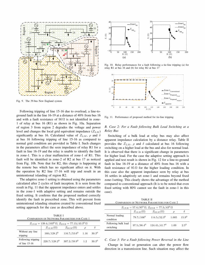
Following tripping of line 15-16 due to overload, a line-to-ground fault in the line 16-19 at a distance of 40% from bus 16and with a fault resistance of 90 Ω is not identified in zone-1 of relay at bus 16 (R1) as shown in Fig. 10a. Separationof region 3 from region 2 degrades the voltage and powerlevel and changes the local grid equivalent impedance (ZLM )significantly at bus 16. Calculated value of ZLM , ρ and δat bus 16 following tripping of line 15-16 as compared tonormal grid condition are provided in Table I. Such changesin the parameters affect the seen impedance of relay R1 for afault in line 16-19 and the relay is unable to identify the faultin zone-1. This is a clear malfunction of zone-1 of R1. Thisfault will be identified in zone-2 of R2 at bus 17 as noticedfrom Fig. 10b. Note that for R2, this change is happening atthe remote bus which has no significant affect on it. Withthe operation by R2 line 17-16 will trip and result in anunintentional islanding of region R2.
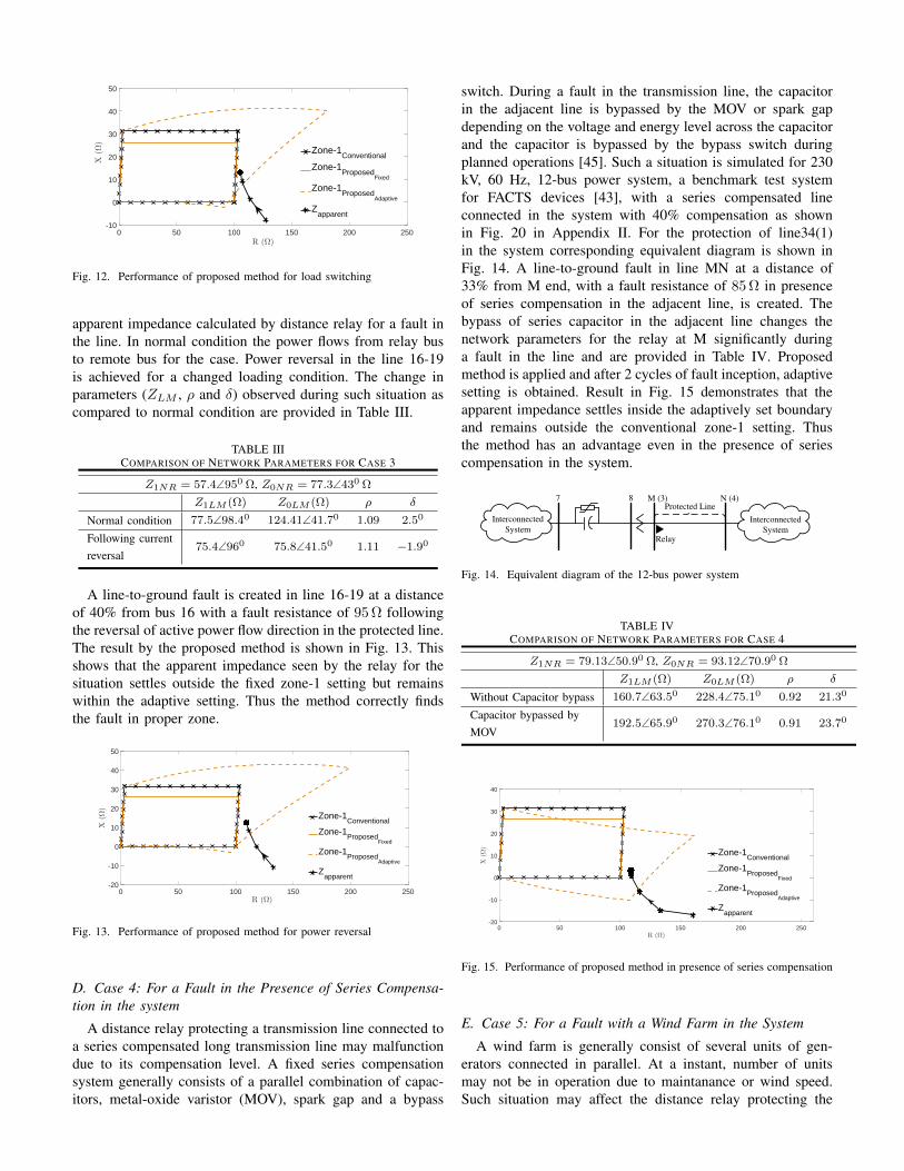
The adaptive zone-1 setting is obtained using the parameterscalculated after 2 cycles of fault inception. It is seen from theresult in Fig. 11 that the apparent impedance enters and settlesin the zone-1 with adaptive setting and remains outside thefixed setting. It confirms that the proposed method correctlyidentify the fault in prescribed zone. This will prevent fromunintentional islanding situation created by conventional fixedsetting approach for the case as described above.
TABLE ICOMPARISON OF NETWORK PARAMETERS FOR CASE 1
Z1NR = 139.4∠1030 Ω, Z0NR = 77.13∠43.30 Ω
Z1LM (Ω) Z0LM (Ω) ρ δ
Without any linetripping
160∠128.20 116.7∠53.60 1.16 30.30
Following trippingof line 15-16
220.7∠128.20 307.2∠59.90 1.2 30.30
0 50 100 150 2000
10
20
30
40
50
R (Ω)
X(Ω
)
0 50 100 150 200−10
0
10
20
30
40
R (Ω)
X(Ω
)
Zone1R1
Zapp
R1
Zone1R2
Zone2R2
Zapp
R2
(a) (b)
Fig. 10. Relay performances for a fault following a tie-line tripping (a) forrelay R1 at bus 16 and (b) for relay R2 at bus 17
0 20 40 60 80 100 120 140 160 180 200 220R (Ω)
-10
0
10
20
30
40
X(Ω
)
Zone-1Conventional
Zone-1Proposed
Fixed
Zone-1Proposed
Adaptive
Zapparent
Fig. 11. Performance of proposed method for tie-line tripping
B. Case 2: For a Fault following Bulk Load Switching at aRelay Bus
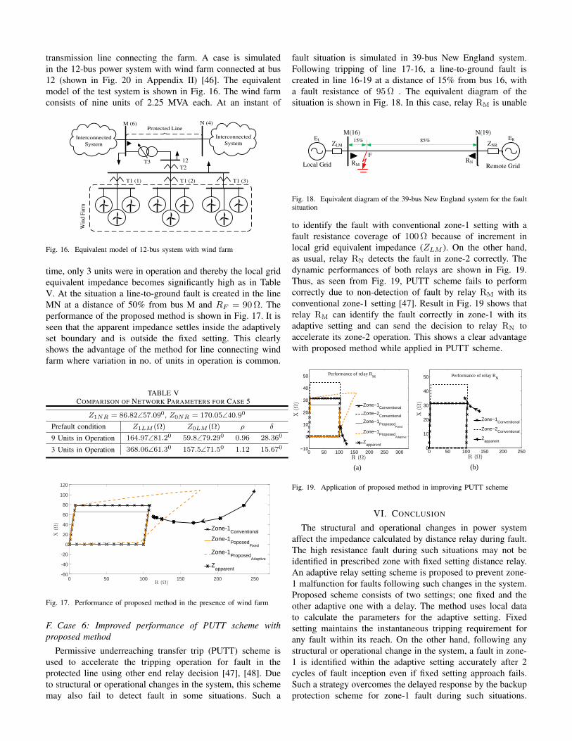
Switching of a bulk load at relay bus may also affectapparent impedance calculation by a distance relay. Table IIprovides the ZLM , ρ and δ calculated at bus 16 followingswitching on a higher load at the bus and also for normal load.It is observed that there is a significant change in parametersfor higher load. For the case the adaptive setting approach isapplied and test result is shown in Fig. 12 for a line-to-groundfault in line 16-19 at a distance of 40% from bus 16 with afault resistance of 95 Ω for the higher loading condition. Inthis case also the apparent impedance seen by relay at bus16 settles in adaptively set zone-1 and remains beyond fixedzone-1setting. This clearly shows the advantage of the methodcompared to conventional approach (It is to be noted that evenfixed setting with 80% cannot see the fault in zone-1 in thiscase).
TABLE IICOMPARISON OF NETWORK PARAMETERS FOR CASE 2
Z1NR = 57.4∠950 Ω, Z0NR = 77.3∠430 Ω
Z1LM (Ω) Z0LM (Ω) ρ δ
Normal loadingcondition
79.7∠1060 114.5∠52.30 1.005 15.90
Following bulk loadswitching
97.5∠98.40 124.41∠41.70 1.09 2.50
C. Case 3: For a Fault following Power Reversal in the Line
Change in load or generation can alter the power flowdirection in a transmission line. Such situation may affect the
0 50 100 150 200 250R (Ω)
-10
0
10
20
30
40
50X
(Ω)
Zone-1Conventional
Zone-1Proposed
Fixed
Zone-1Proposed
Adaptive
Zapparent
Fig. 12. Performance of proposed method for load switching
apparent impedance calculated by distance relay for a fault inthe line. In normal condition the power flows from relay busto remote bus for the case. Power reversal in the line 16-19is achieved for a changed loading condition. The change inparameters (ZLM , ρ and δ) observed during such situation ascompared to normal condition are provided in Table III.
TABLE IIICOMPARISON OF NETWORK PARAMETERS FOR CASE 3
Z1NR = 57.4∠950 Ω, Z0NR = 77.3∠430 Ω
Z1LM (Ω) Z0LM (Ω) ρ δ
Normal condition 77.5∠98.40 124.41∠41.70 1.09 2.50
Following currentreversal
75.4∠960 75.8∠41.50 1.11 −1.90
A line-to-ground fault is created in line 16-19 at a distanceof 40% from bus 16 with a fault resistance of 95 Ω followingthe reversal of active power flow direction in the protected line.The result by the proposed method is shown in Fig. 13. Thisshows that the apparent impedance seen by the relay for thesituation settles outside the fixed zone-1 setting but remainswithin the adaptive setting. Thus the method correctly findsthe fault in proper zone.
0 50 100 150 200 250R (Ω)
-20
-10
0
10
20
30
40
50
X(Ω
)
Zone-1Conventional
Zone-1Proposed
Fixed
Zone-1Proposed
Adaptive
Zapparent
Fig. 13. Performance of proposed method for power reversal
D. Case 4: For a Fault in the Presence of Series Compensa-tion in the system
A distance relay protecting a transmission line connected toa series compensated long transmission line may malfunctiondue to its compensation level. A fixed series compensationsystem generally consists of a parallel combination of capac-itors, metal-oxide varistor (MOV), spark gap and a bypass
switch. During a fault in the transmission line, the capacitorin the adjacent line is bypassed by the MOV or spark gapdepending on the voltage and energy level across the capacitorand the capacitor is bypassed by the bypass switch duringplanned operations [45]. Such a situation is simulated for 230kV, 60 Hz, 12-bus power system, a benchmark test systemfor FACTS devices [43], with a series compensated lineconnected in the system with 40% compensation as shownin Fig. 20 in Appendix II. For the protection of line34(1)in the system corresponding equivalent diagram is shown inFig. 14. A line-to-ground fault in line MN at a distance of33% from M end, with a fault resistance of 85 Ω in presenceof series compensation in the adjacent line, is created. Thebypass of series capacitor in the adjacent line changes thenetwork parameters for the relay at M significantly duringa fault in the line and are provided in Table IV. Proposedmethod is applied and after 2 cycles of fault inception, adaptivesetting is obtained. Result in Fig. 15 demonstrates that theapparent impedance settles inside the adaptively set boundaryand remains outside the conventional zone-1 setting. Thusthe method has an advantage even in the presence of seriescompensation in the system.
Interconnected
System
Interconnected
System
M (3) N (4)Protected Line
Relay
87
Fig. 14. Equivalent diagram of the 12-bus power system
TABLE IVCOMPARISON OF NETWORK PARAMETERS FOR CASE 4
Z1NR = 79.13∠50.90 Ω, Z0NR = 93.12∠70.90 Ω
Z1LM (Ω) Z0LM (Ω) ρ δ
Without Capacitor bypass 160.7∠63.50 228.4∠75.10 0.92 21.30
Capacitor bypassed byMOV
192.5∠65.90 270.3∠76.10 0.91 23.70
0 50 100 150 200 250R (Ω)
-20
-10
0
10
20
30
40
X(Ω
)
Zone-1Conventional
Zone-1Proposed
Fixed
Zone-1Proposed
Adaptive
Zapparent
Fig. 15. Performance of proposed method in presence of series compensation
E. Case 5: For a Fault with a Wind Farm in the System
A wind farm is generally consist of several units of gen-erators connected in parallel. At a instant, number of unitsmay not be in operation due to maintanance or wind speed.Such situation may affect the distance relay protecting the
transmission line connecting the farm. A case is simulatedin the 12-bus power system with wind farm connected at bus12 (shown in Fig. 20 in Appendix II) [46]. The equivalentmodel of the test system is shown in Fig. 16. The wind farmconsists of nine units of 2.25 MVA each. At an instant of
Interconnected
System
Interconnected
System
Protected Line
T1 (1) T1 (2) T1 (3)
T2T3
Win
dF
arm
M (6)
12
N (4)
Fig. 16. Equivalent model of 12-bus system with wind farm
time, only 3 units were in operation and thereby the local gridequivalent impedance becomes significantly high as in TableV. At the situation a line-to-ground fault is created in the lineMN at a distance of 50% from bus M and RF = 90 Ω. Theperformance of the proposed method is shown in Fig. 17. It isseen that the apparent impedance settles inside the adaptivelyset boundary and is outside the fixed setting. This clearlyshows the advantage of the method for line connecting windfarm where variation in no. of units in operation is common.
TABLE VCOMPARISON OF NETWORK PARAMETERS FOR CASE 5
Z1NR = 86.82∠57.090, Z0NR = 170.05∠40.90
Prefault condition Z1LM (Ω) Z0LM (Ω) ρ δ
9 Units in Operation 164.97∠81.20 59.8∠79.290 0.96 28.360
3 Units in Operation 368.06∠61.30 157.5∠71.50 1.12 15.670
0 50 100 150 200 250R (Ω)
-60
-40
-20
0
20
40
60
80
100
120
X(Ω
)
Zone-1Conventional
Zone-1Poposed
Fixed
Zone-1Proposed
Adaptive
Zapparent
Fig. 17. Performance of proposed method in the presence of wind farm
F. Case 6: Improved performance of PUTT scheme withproposed method
Permissive underreaching transfer trip (PUTT) scheme isused to accelerate the tripping operation for fault in theprotected line using other end relay decision [47], [48]. Dueto structural or operational changes in the system, this schememay also fail to detect fault in some situations. Such a
fault situation is simulated in 39-bus New England system.Following tripping of line 17-16, a line-to-ground fault iscreated in line 16-19 at a distance of 15% from bus 16, witha fault resistance of 95 Ω . The equivalent diagram of thesituation is shown in Fig. 18. In this case, relay RM is unable
EL ER
ZLM ZNR
Local Grid Remote GridRM
M(16) N(19)
FRN
15% 85%
Fig. 18. Equivalent diagram of the 39-bus New England system for the faultsituation
to identify the fault with conventional zone-1 setting with afault resistance coverage of 100 Ω because of increment inlocal grid equivalent impedance (ZLM ). On the other hand,as usual, relay RN detects the fault in zone-2 correctly. Thedynamic performances of both relays are shown in Fig. 19.Thus, as seen from Fig. 19, PUTT scheme fails to performcorrectly due to non-detection of fault by relay RM with itsconventional zone-1 setting [47]. Result in Fig. 19 shows thatrelay RM can identify the fault correctly in zone-1 with itsadaptive setting and can send the decision to relay RN toaccelerate its zone-2 operation. This shows a clear advantagewith proposed method while applied in PUTT scheme.
0 50 100 150 200 250 300−10
0
10
20
30
40
50
R (Ω)
X(Ω
)
0 50 100 150 200 2500
10
20
30
40
50
R (Ω)
X(Ω
)
Zone−1Conventional
Zone−2Conventional
Zapparent
Zone−1Conventional
Zone−2Conventional
Zone−1Proposed
Fixed
Zone−1Proposed
Adaptive
Zapparent
Performance of relay RM Performance of relay R
N
(a) (b)
Fig. 19. Application of proposed method in improving PUTT scheme
VI. CONCLUSION
The structural and operational changes in power systemaffect the impedance calculated by distance relay during fault.The high resistance fault during such situations may not beidentified in prescribed zone with fixed setting distance relay.An adaptive relay setting scheme is proposed to prevent zone-1 malfunction for faults following such changes in the system.Proposed scheme consists of two settings; one fixed and theother adaptive one with a delay. The method uses local datato calculate the parameters for the adaptive setting. Fixedsetting maintains the instantaneous tripping requirement forany fault within its reach. On the other hand, following anystructural or operational change in the system, a fault in zone-1 is identified within the adaptive setting accurately after 2cycles of fault inception even if fixed setting approach fails.Such a strategy overcomes the delayed response by the backupprotection scheme for zone-1 fault during such situations.
The improved performance of the method is demonstratedfor different situations such as tie-line tripping, bulk loadswitching, power reversal, presence of series compensationand with wind power integration. This method is found tobe advantageous to PUTT scheme following such a changedsituation in the system.
APPENDIX I
For a phase A-to-ground fault at F in Fig. 2, the sequencecurrents through the fault resistance become
I1F = I2F = I0F =VAFpre
(Ceq + CRF)
(15)
where VAFpre is the prefault phase A voltage at F. Ceq andCRF
are the equivalent sum of the sequence impedances andfault resistance of the network in Fig. 5 respectively and aredefined as
Ceq =2(Z1LM + xZ1L)(Z1NR + (1 − x)Z1L)
(Z1LM + xZ1L) + (Z1NR + (1 − x)Z1L)
+(Z0LM + xZ0L)(Z0NR + (1 − x)Z0L)
(Z0LM + xZ0L) + (Z0NR + (1 − x)Z0L)
(16)
CRF= 3RF (17)
The distribution of sequence currents at bus M can be ex-pressed as
I1M = I2M = C12I1F (18)
I0M = C0I0F (19)
The current distribution factors involved in (18) and (19) aredefined as
C12 =(Z1NR + (1 − x)Z1L)
(Z1NR + (1 − x)Z1L) + (Z1LM + xZ1L)(20)
C0 =(Z0NR + (1 − x)Z0L)
(Z0NR + (1 − x)Z0L) + (Z0LM + xZ0L)(21)
The phase A apparent impedance calculated by distance relayat bus M during a phase A to ground fault is expressed as
Zapp =VAM
IAM +K0I0M(22)
where VAM and IAM are the voltage and current at phase Aat bus M during fault. The zero sequence compensating factor(K0) is defined as
K0 =Z0L − Z1L
Z1L(23)
Substituting the sequence current components and prefaultvoltage in (22), Zapp can be expressed as
Zapp = xZ1L +CRF
(Ceq + CRF)Cρδ + 2C12 + C0(1 +K0)
(24)where Cρδ is defined as
Cρδ =(1 − ρe−jδ)
(Z1NR + (1 − x)Z1L) + (Z1LM + xZ1L)ρe−jδ(25)
1
2
3
45
6
78
9
10
11
12
Infinite bus
G1
G2
G3
Wind
Farm
Line34(1)
Line34(2)
Fig. 20. The 12-bus power system
APPENDIX IISYSTEM DATA
The transmission line, transformer, generator and load datafor 39 bus New England system used in simulation are asin [42] with little modification on line lengths and loadingconditions to satisfy the requirements for different situations.
The transmission line, transformer and generator with ex-citer data for the 12-bus system are same as in [43].
TABLE VIWIND FARM DATA
No. of Units 9
Generating Unit SCIG, 415 V, 2.25 MVA, 60 Hz
Transformers T1: 415 V/22 kV, 10 MVA, 60 HzT2: 22 kV/110 kV, 50 MVA, 60 HzT3: 110 kV/ 230 kV, 100 MVA, 60 Hz
TABLE VIIDATA FOR INSTRUMENT TRANSFORMERS
For 345 kV, 60 Hz, 39-bus New England system:
Current Transformer Capacitive Voltage Transformer
Ratio : 300:5 Ratio : 3000 : 1Class : 5P40 Total Capacitance : 4400 pFCore : Selectron 53 Intermediate Voltage : 12.7 kV
Class : 3P
For 230 kV, 60 Hz 12-bus system:
Current Transformer Capacitive Voltage Transformer
Ratio : 1000:5 Ratio : 2000 : 1Class : 5P40 Total Capacitance : 4400 pFCore : Selectron 53 Intermediate Voltage : 12.7 kV
Class : 3P
ACKNOWLEDGMENT
The authors are thankful to Department of Scienceand Technology (DST), New Delhi, India, for sponsor-ing the Indo-UK joint project, “Advanced communication
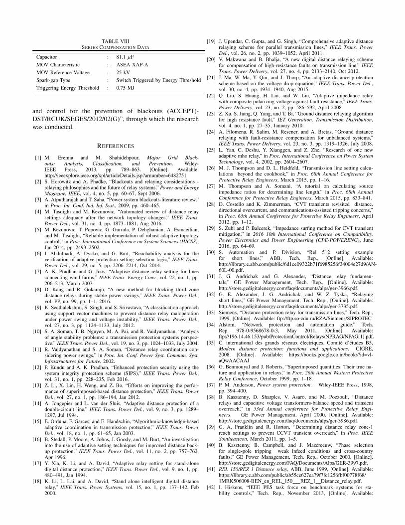
TABLE VIIISERIES COMPENSATION DATA
Capacitor : 81.1 µFMOV Characteristic : ASEA XAP-AMOV Reference Voltage : 25 kVSpark-gap Type : Switch Triggered by Energy ThresholdTriggering Energy Threshold : 0.75 MJ
and control for the prevention of blackouts (ACCEPT)-DST/RCUK/SEGES/2012/02(G)”, through which the researchwas conducted.
REFERENCES
[1] M. Eremia and M. Shahidehpour, Major Grid Black-outs: Analysis, Classification, and Prevention. Wiley-IEEE Press, 2013, pp. 789–863. [Online]. Available:http://ieeexplore.ieee.org/xpl/articleDetails.jsp?arnumber=6482751
[2] S. Horowitz and A. Phadke, “Blackouts and relaying considerations -relaying philosophies and the future of relay systems,” Power and EnergyMagazine, IEEE, vol. 4, no. 5, pp. 60–67, Sept 2006.
[3] A. Atputharajah and T. Saha, “Power system blackouts-literature review,”in Proc. Int. Conf. Ind. Inf. Syst., 2009, pp. 460–465.
[4] M. Tasdighi and M. Kezunovic, “Automated review of distance relaysettings adequacy after the network topology changes,” IEEE Trans.Power Del., vol. 31, no. 4, pp. 1873–1881, Aug 2016.
[5] M. Kezunovic, T. Popovic, G. Gurrala, P. Dehghanian, A. Esmaeilian,and M. Tasdighi, “Reliable implementation of robust adaptive topologycontrol,” in Proc. International Conference on System Sciences (HICSS),Jan 2014, pp. 2493–2502.
[6] I. Abdulhadi, A. Dysko, and G. Burt, “Reachability analysis for theverification of adaptive protection setting selection logic,” IEEE Trans.Power Del., vol. 29, no. 5, pp. 2206–2214, Oct 2014.
[7] A. K. Pradhan and G. Joos, “Adaptive distance relay setting for linesconnecting wind farms,” IEEE Trans. Energy Conv., vol. 22, no. 1, pp.206–213, March 2007.
[8] D. Kang and R. Gokaraju, “A new method for blocking third zonedistance relays during stable power swings,” IEEE Trans. Power Del.,vol. PP, no. 99, pp. 1–1, 2016.
[9] K. Seethalekshmi, S. Singh, and S. Srivastava, “A classification approachusing support vector machines to prevent distance relay maloperationunder power swing and voltage instability,” IEEE Trans. Power Del.,vol. 27, no. 3, pp. 1124–1133, July 2012.
[10] S. A. Soman, T. B. Nguyen, M. A. Pai, and R. Vaidyanathan, “Analysisof angle stability problems: a transmission protection systems perspec-tive,” IEEE Trans. Power Del., vol. 19, no. 3, pp. 1024–1033, July 2004.
[11] R. Vaidyanathan and S. A. Soman, “Distance relay coordination con-sidering power swings,” in Proc. Int. Conf. Power Syst. Commun. Syst.Infrastructures for Future, 2002.
[12] P. Kundu and A. K. Pradhan, “Enhanced protection security using thesystem integrity protection scheme (SIPS),” IEEE Trans. Power Del.,vol. 31, no. 1, pp. 228–235, Feb 2016.
[13] Z. Li, X. Lin, H. Weng, and Z. Bo, “Efforts on improving the perfor-mance of superimposed-based distance protection,” IEEE Trans. PowerDel., vol. 27, no. 1, pp. 186–194, Jan 2012.
[14] A. Jongepier and L. van der Sluis, “Adaptive distance protection of adouble-circuit line,” IEEE Trans. Power Del., vol. 9, no. 3, pp. 1289–1297, Jul 1994.
[15] E. Orduna, F. Garces, and E. Handschin, “Algorithmic-knowledge-basedadaptive coordination in transmission protection,” IEEE Trans. PowerDel., vol. 18, no. 1, pp. 61–65, Jan 2003.
[16] B. Stedall, P. Moore, A. Johns, J. Goody, and M. Burt, “An investigationinto the use of adaptive setting techniques for improved distance back-up protection,” IEEE Trans. Power Del., vol. 11, no. 2, pp. 757–762,Apr 1996.
[17] Y. Xia, K. Li, and A. David, “Adaptive relay setting for stand-alonedigital distance protection,” IEEE Trans. Power Del., vol. 9, no. 1, pp.480–491, Jan 1994.
[18] K. Li, L. Lai, and A. David, “Stand alone intelligent digital distancerelay,” IEEE Trans. Power Systems, vol. 15, no. 1, pp. 137–142, Feb2000.
[19] J. Upendar, C. Gupta, and G. Singh, “Comprehensive adaptive distancerelaying scheme for parallel transmission lines,” IEEE Trans. PowerDel., vol. 26, no. 2, pp. 1039–1052, April 2011.
[20] V. Makwana and B. Bhalja, “A new digital distance relaying schemefor compensation of high-resistance faults on transmission line,” IEEETrans. Power Delivery, vol. 27, no. 4, pp. 2133–2140, Oct 2012.
[21] J. Ma, W. Ma, Y. Qiu, and J. Thorp, “An adaptive distance protectionscheme based on the voltage drop equation,” IEEE Trans. Power Del.,vol. 30, no. 4, pp. 1931–1940, Aug 2015.
[22] Q. Liu, S. Huang, H. Liu, and W. Liu, “Adaptive impedance relaywith composite polarizing voltage against fault resistance,” IEEE Trans.Power Delivery, vol. 23, no. 2, pp. 586–592, April 2008.
[23] Z. Xu, S. Jiang, Q. Yang, and T. Bi, “Ground distance relaying algorithmfor high resistance fault,” IET Generation, Transmission Distribution,vol. 4, no. 1, pp. 27–35, January 2010.
[24] A. Filomena, R. Salim, M. Resener, and A. Bretas, “Ground distancerelaying with fault-resistance compensation for unbalanced systems,”IEEE Trans. Power Delivery, vol. 23, no. 3, pp. 1319–1326, July 2008.
[25] L. Yan, C. Deshu, Y. Xianggen, and Z. Zhe, “Research of one newadaptive mho relay,” in Proc. International Conference on Power SystemTechnology, vol. 4, 2002, pp. 2604–2607.
[26] M. J. Thompson and D. L. Heidfeld, “Transmission line setting calcu-lations beyond the cookbook,” in Proc. 68th Annual Conference forProtective Relay Engineers, March 2015, pp. 1–16.
[27] M. Thompson and A. Somani, “A tutorial on calculating sourceimpedance ratios for determining line length,” in Proc. 68th AnnualConference for Protective Relay Engineers, March 2015, pp. 833–841.
[28] D. Costello and K. Zimmerman, “CVT transients revisited distance,directional overcurrent, and communications-assisted tripping concerns,”in Proc. 65th Annual Conference for Protective Relay Engineers, April2012, pp. 1–12.
[29] S. Zubi and P. Balcerek, “Impedance surfing method for CVT transientmitigation,” in 2016 10th International Conference on Compatibility,Power Electronics and Power Engineering (CPE-POWERENG), June2016, pp. 64–69.
[30] S. Automation and P. Division, “Rel 512 setting examplefor short lines,” ABB, Tech. Rep., [Online]. Available:http://library.e.abb.com/public/6d1ce09322b71f6985256f34004e27d9/AN-60L-00.pdf.
[31] J. G. Andrichak and G. Alexander, “Distance relay fundamen-tals,” GE Power Management, Tech. Rep., [Online]. Available:http://store.gedigitalenergy.com/faq/documents/alps/ger-3966.pdf.
[32] G. E. Alexander, J. G. Andrichak, and W. Z. Tyska, “Relayingshort lines,” GE Power Management, Tech. Rep., [Online]. Available:http://store.gedigitalenergy.com/faq/documents/alps/ger-3735.pdf.
[33] Siemens, “Distance protection relay for transmission lines,” Tech. Rep.,1999, [Online]. Available: ftp://ftp.so-cdu.ru/RZA/Siemens/SIPROTEC
[34] Alstom, “Network protection and automation guide,” Tech.Rep. 978-0-9568678-0-3, May 2011, [Online]. Available:ftp://196.14.46.153/pub/ProtectionControl/Relays/NPRAG/NPAG[1].pdf.
[35] C. international des grands reseaux electriques. Comite d’etudes B5,Modern distance protection: functions and applications. CIGRE,2008. [Online]. Available: https://books.google.co.in/books?id=vl-aQwAACAAJ
[36] G. Benmouyal and J. Roberts, “Superimposed quantities: Their true na-ture and application in relays,” in Proc. 26th Annual Western ProtectiveRelay Conference, October 1999, pp. 1–18.
[37] P. M. Anderson, Power system protection. Wiley-IEEE Press, 1998,pp. 394–400.
[38] B. Kasztenny, D. Sharples, V. Asaro, and M. Pozzouli, “Distancerelays and capacitive voltage transformers-balance speed and transientoverreach,” in 53rd Annual conference for Protective Relay Engi-neers. GE Power Management, April 2000, [Online]. Available:http://store.gedigitalenergy.com/faq/documents/alps/ger-3986.pdf.
[39] G. A. Franklin and R. Horton, “Determining distance relay zone-1reach settings to prevent CCVT transient overreach,” in Proc. IEEESoutheastcon, March 2011, pp. 1–5.
[40] B. Kasztenny, B. Campbell, and J. Mazereeuw, “Phase selectionfor single-pole tripping weak infeed conditions and cross-countryfaults,” GE Power Management, Tech. Rep., October 2000, [Online].http://store.gedigitalenergy.com/FAQ/Documents/Alps/GER-3997.pdf.
[41] REL 150/REZ 1 Distance relay, ABB, June 1999, [Online]. Available:https://library.e.abb.com/public/ab55ce627ea79f7fc1256fbf00778f68/1MRK506008-BEN en REL 150 REZ 1 Distance relay.pdf.
[42] I. Hiskens, “IEEE PES task force on benchmark systems for sta-bility controls,” Tech. Rep., November 2013, [Online]. Available:

http://eioc.pnnl.gov/benchmark/ieeess/IEEE39/New England Reduced
BIOGRAPHIES
Subhadeep Paladhi (S’14) received the B.E. degreein Electrical Engineering from University of Burd-wan, India, in 2013 and M. Tech. degree in PowerSystems from National Institute of Technology Cali-cut, India in 2015. He is currently working towardthe PhD degree in Electrical Engineering at IndianInstitute of Technology, Kharagpur, India.
His current research interests include Power Sys-tem Protection.
Ashok Kumar Pradhan (SM’10, M’94) receivedthe Ph.D. degree in Electrical Engineering fromSambalpur University, Sambalpur, India, in 2001.
He has been with the Department of ElectricalEngineering, Indian Institute of Technology, Kharag-pur, India, since 2002, where he is currently aProfessor. He served at the Department of ElectricalEngineering, VSS University of Technology, Burla,India from 1992-2002. His research interests includepower system relaying and monitoring.
Prof. Pradhan is a Fellow of Indian NationalAcademy of Engineering (INAE) India.
Model (39 bus system) MATLAB study report.pdf.
[43] S. Jiang, U. Annakkage, and A. Gole, “A platform for validation ofFACTS models,” IEEE Trans. Power Del., vol. 21, no. 1, pp. 484–491,Jan 2006.
[44] Powergrid, “Report of the enquiry committee on grid disturbancein northern region on 30th July 2012 and in northern,eastern and north-eastern region on 31st July 2012,” NewDelhi, India, Tech. Rep., Aug 2012, [Online]. Available:http://www.powermin.nic.in/pdf/GRID ENQ REP 16 8 12.pdf.
[45] J. Miller, M. Brunet-Watson, and J. Leighfield, “Review of seriescompensation for transmission lines,” PSC North America, Tech. Rep.,May 2014.
[46] A. Adamczyk, M. Altin, O. Goksu, R. Teodorescu, and F. Iov, “Generic12-bus test system for wind power integration studies,” in 15th EuropeanConference on Power Electronics and Applications (EPE), Sept 2013,pp. 1–6.
[47] H. J. A. Ferrer(editor) and E. O. SchweitzerIII(editor), Modern solutionsfor protection, control, and monitoring of electric power systems.Pullman, Wash. (2350 NE Hopkins Court, Pullman, WA 99163 USA)Schweitzer Engineering Laboratories, 2010, pp. 79–83.
[48] S. H. Horowitz and A. G. Phadke, Power system relaying. John Wiley& Sons, 2008, pp. 147–148.
Related Documents