357 AMSE JOURNALS-AMSE IIETA publication-2017-Series: Advances B; Vol. 60; N°2; pp 357-371 Submitted Aug. 28, 2017; Revised Oct. 13, 2017; Accepted Oct. 16, 2017 Adaptive Wavelet Transform Based Rake Receiver for Ultra- Wideband Systems *Ch. Navitha, **K. Sivani K., ***Ashoka Reddy* *,***Dept. of Electronics & Communication Engineering, Kakatiya Institute of Technology & Science, Warangal, Telangana, India ([email protected]) **Dept. of Electronics & Instrumentation Engineering, Kakatiya Institute of Technology & Science, Warangal, Telangana, India Abstract This paper proposes a dual-tree complex wavelet transform (DTCWT) based adaptive rake receiver for Ultra-Wideband (UWB) systems. Advantage of using dual tree complex wavelet transform is that instead of capturing the signal energy in different multipath components at different delays, it captures them at different frequency components. LMS equalizer used in the receiver structure reduces the ISI. This adaptive scheme does not require all the parameters of the multipath components, but a short training period is only required to adjust the tap weights. The performance of the proposed receiver is evaluated and compared with existing conventional adaptive rake receiver and adaptive continuous wavelet transform rake receiver. All possible rake combinations such as ARAKE, SRAKE and PRAKE are considered, and it is found that the performance of the proposed system has shown a significant SNR improvement of 5-6 dB over conventional adaptive rake receiver. Key words UWB system, Rake receiver, Wavelet transform, DTCWT. 1. Introduction The interest for low cost, fast, wireless connections for short range (<10 m) communication

Welcome message from author
This document is posted to help you gain knowledge. Please leave a comment to let me know what you think about it! Share it to your friends and learn new things together.
Transcript

357
AMSE JOURNALS-AMSE IIETA publication-2017-Series: Advances B; Vol. 60; N°2; pp 357-371
Submitted Aug. 28, 2017; Revised Oct. 13, 2017; Accepted Oct. 16, 2017
Adaptive Wavelet Transform Based Rake Receiver for Ultra-
Wideband Systems
*Ch. Navitha, **K. Sivani K., ***Ashoka Reddy*
*,***Dept. of Electronics & Communication Engineering, Kakatiya Institute of Technology &
Science, Warangal, Telangana, India ([email protected])
**Dept. of Electronics & Instrumentation Engineering, Kakatiya Institute of Technology &
Science, Warangal, Telangana, India
Abstract
This paper proposes a dual-tree complex wavelet transform (DTCWT) based adaptive rake
receiver for Ultra-Wideband (UWB) systems. Advantage of using dual tree complex wavelet
transform is that instead of capturing the signal energy in different multipath components at
different delays, it captures them at different frequency components. LMS equalizer used in the
receiver structure reduces the ISI. This adaptive scheme does not require all the parameters of the
multipath components, but a short training period is only required to adjust the tap weights. The
performance of the proposed receiver is evaluated and compared with existing conventional
adaptive rake receiver and adaptive continuous wavelet transform rake receiver. All possible rake
combinations such as ARAKE, SRAKE and PRAKE are considered, and it is found that the
performance of the proposed system has shown a significant SNR improvement of 5-6 dB over
conventional adaptive rake receiver.
Key words
UWB system, Rake receiver, Wavelet transform, DTCWT.
1. Introduction
The interest for low cost, fast, wireless connections for short range (<10 m) communication

358
is significantly expanding every day. The UWB system is a promising technology that gives a
high information rate which makes it appropriate to be utilized as a part of many fields. The
UWB transmission enables it to be utilized with systems and in many fields like PAN (Personal
Area Network), WLAN (Wireless Local Area Network) and multimedia transmission
frameworks and in the biomedical and military fields [1], [2]. A UWB system depends on the
transmission of a train of ultra-short pulses over a wide bandwidth. As indicated by the FCC
(Federal Communication Committee) regulations, the UWB frameworks are permitted to transmit
over the frequency band of 3.1 to 10.6 GHz. The vast data transfer capacity secured by UWB
frameworks, builds its possibility of interfering with other narrowband and wideband frameworks
utilizing the low Gigahertz frequency bands. Therefore, the FCC regulations limit the UWB
transmission. Where, the UWB frameworks can transmit just utilizing low power. The achievable
data rates and transmission range of the system is limited by these strict regulations on the UWB
system in addition to the channel effect which is extremely frequency selective [2], [3]. Since
UWB transmits data utilizing ultra-short pulses in nanosecond, the UWB channel is enhanced
with resolvable multipath components (i.e. it has a dense multipath condition). Thus, the received
waveform is made up of many scaled and delayed replicas of transmitted signal.
Performance of the UWB system is enhanced by using a rake receiver that introduces
multipath diversity to capture the most of the energy of the multipath components. A large
number of rake fingers are required to transfer most of the transmission energy spread over the
multipath components (correlator’s template waveforms are the delayed versions of the
transmitted pulse). That is also the large range of channel parameters are need to estimated
[2],[3].
A large number of research papers were presented on the Rake receiver which also includes
the study of the performance of the partial, chip, or symbol delays spacing Rake with channel
estimator [4]. Its execution was additionally studied with two combining strategies the MRC and
SLC (Square Law Combiner) in [5]. Likewise a Selective Rake (SRake) receiver which tracks the
strongest L multipath components is proposed in [6] with its execution exhibited. The Rake
receiver is additionally examined with a MISO space–time coding utilizing MRC Rake receiver
in [7] and [8], to make utilization of multipath diversity in addition to spatial diversity and thus
improve the channel capacity. In [1] a smart UWB framework depending upon the utilization of
analog STC scheme I (STC-I) with a GA Rake receiver was proposed that adaptively chooses the
fingers delays to catch multipath components with maximum gain. A great enhancement in SNR
for a single user scheme was showed by the smart UWB system. Its execution is additionally
considered in combatting interference from other UWB frameworks utilizing Time Reversal (TR)

359
pre-coding method [9]. To accomplish an information rate of not less than 110Mbps for each user
in UWB communication, the required symbol time should not exceed 10ns. As per [10], there is
rms delay spread of 15ms for a channel model used for a range of 4-10 meter in Non-Line-of-
sight environment. This spread shows that there is a significant inter-symbol interference (ISI) in
fast UWB communication frameworks. The rake receiver just combines the energy of multipath
components but does not prevent ISI. In [11], a rake- MMSE-equalizer structure was proposed.
By far most of distributed outcomes on UWB ignored this reality as most execution
investigations utilize a rake receiver under the presumption that channel delay spreads are a great
deal not as much as the symbol time [12,13]. The wavelet transform (WT) has been widely
utilized in the wireless communication field exclusively in UWB communication [14]. The WT
was presented in [15] as new modulation scheme WSK (Wavelet Shift Keying) which is
considered as a speculation of "Wavelet based orthogonal frequency division multiplexing
(OFDM)". Likewise the OFDM scheme qualities are upgraded by utilizing orthogonal wavelet
division multiplexing (OWDM) in a Rayleigh fading channel as represented in [16]. Then again
the OFDM framework is considered with discrete wavelet transform (DWT) and discrete multi-
wavelet transform (DMWT) to reduce the level of interference and increase the spectral
efficiency in [17]. It is appeared in [18] that DMWT–OFDM proposes much lower bit error rate
(BER), increases the signal to noise ratio (SNR), and therefore can be utilized as an alternative to
the ordinary OFDM. Complex wavelet pulses enabling PSK Modulation for UWB impulse radio
communications was presented in [19]. Continuous wavelet transform based rake receiver is
designed and implemented in [20] for an UWB systems with high data rate. In [21] estimation of
TOA for an OFDM-UWB based system is investigated with the help of wavelet packet transform.
In [22] the performance for UWB communication systems using different optimal model
techniques in a RAKE receiver is investigated.
In this paper, we present a novel dual tree complex wavelet transform (DTCWT) based
adaptive rake receiver. This paper is organized as follows: Section 2 is focused on the UWB
transmit model, UWB channel model, and the rake receiver in brief. Section 3 explains about the
adaptive equalization technique, section 4 deals with the proposed rake receiver and section 5
gives the simulation results analysis. Section 6 concludes the paper.
2. System Model
This section, presents the system model used in this paper for an UWB systems for pear-to-
pear communication. In the UWB communications binary symbols S= ±1 are transmitted over a
train of ultra-short pulses. The binary symbol is pulse shaped by monocycle pulse (Gaussian

360
pulse 2nd derivative). Then the symbols are modulated by Pulse Amplitude Modulation (PAM)
modulation and transmitted repeatedly over Nf frames each of time duration Tf (Ts= Nf*Tf, where
Ts is the symbol duration). The pulse repetition, distribute the symbol energy over multiple
frames of pulses to satisfy the FCC power regulations [14]. The pulse waveform w(t) has typical
duration Tw between 0.2–2ns, resulting in transmission over an ultra-wide bandwidth. The
transmitted waveform for the binary symbol S is given by
1
0
( ) ( )f
f
N
f f
nf
ES t s w t n T
N
(1)
where, E is the symbol energy, and pulse shape w(t) is of unit energy. The multipath channel can
be expressed in terms of multipath delays and gains as given below.
1
0
( ) ( ) ( )M
m
h t m t m
(2)
where h(t) is the impulse response of the UWB channel, α(m) and τ(m) are gain and delay.
Impulse response of the UWB channel model in frequency domain is given as
( ) ( ) jwtH w h t e dt
(3)
where H(ω) is the Fourier transform of h(t), ω is the angular frequency.
Note that, τ(m) > τ(m-1), and Tm = τ(M -1) is the maximum delay spread of the dense
multipath channel.
In the traditional RAKE structure, there are L delayed pulse-matched filters and combiners.
Because here the resolution of the multi-path profile is 1/W, a sample alternative way to
implement the traditional RAKE structure is considered. It just requires only one pulse-matched
filter and sampling its output at W, the process is now a pure digital signal processing after all.
Here assuming that system is perfectly synchronized, the pulse energy is 1 and no inter-pulse
interference exists. Then this digital signal can be expressed in the form:
361
1
( ) ( ) ( )L
n n
n
r t s t n t
(4)
where s(t) is the transmitted symbol, L is number of paths, n(t) is the additive white Gaussian
noise, τn is the delay of nth path and αn is the gain of nth path.
According to the UWB channel model from IEEE P802.15 [15], there are about 60 delayed
paths which capture 85% total energy in the 4-10 meter range and non line of sight. In this paper
Rake receiver is performance is evaluated by considering all the paths (ARAKE), N-selected
paths (SRAKE) and first arriving multipath components (PRAKE). To implement a RAKE
receiver, the arrival time, amplitude and phase of the fingers need to be estimated, a pilot signal
approach is used in this investigation. Np pilot bits are to be transmitted at the beginning of every
data packet for channel estimation purpose. This results in a computational delay. In order to
maximize the signal-to-noise ratio (SNR), MRC is used to collect the multipath diversity in two
levels: The first level is to combine the fingers output of the Rake receiver for each frame. The
second one is to combine the frames corresponding to the same symbol and finally to reduce the
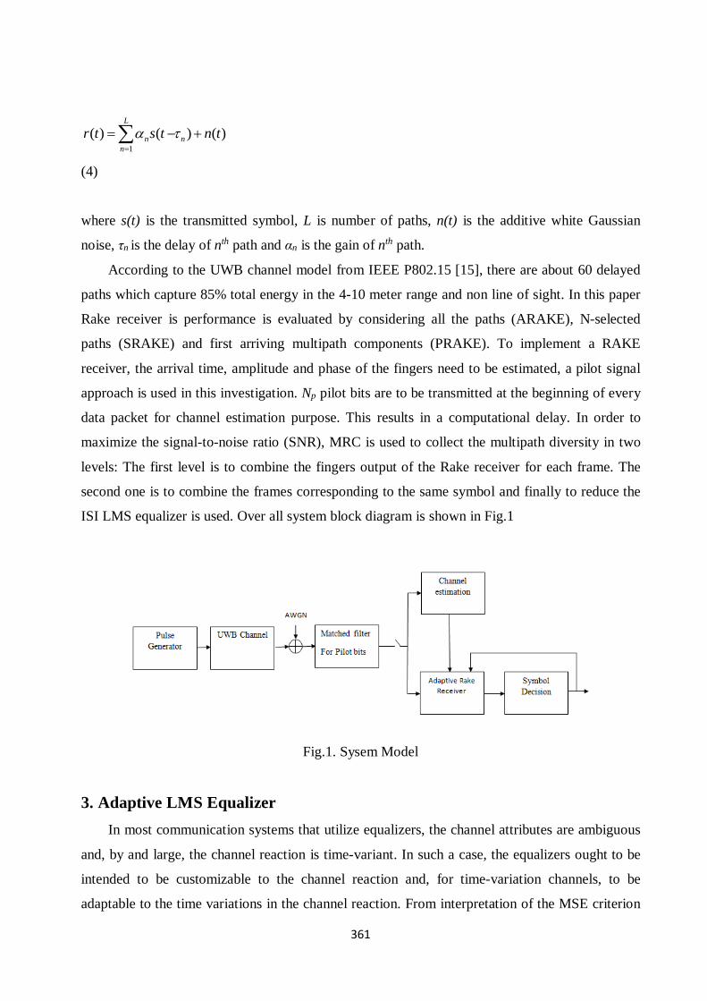
ISI LMS equalizer is used. Over all system block diagram is shown in Fig.1
Fig.1. Sysem Model
3. Adaptive LMS Equalizer
In most communication systems that utilize equalizers, the channel attributes are ambiguous
and, by and large, the channel reaction is time-variant. In such a case, the equalizers ought to be
intended to be customizable to the channel reaction and, for time-variation channels, to be
adaptable to the time variations in the channel reaction. From interpretation of the MSE criterion

362
linear equalization, an ideal tap weight coefficient ( ˆk
I ) can be obtained by solving a set of linear
equations. This coefficient can be recursively acquired by the technique for steepest descent. This
strategy is the fundamental of the LMS adaptive equalization. The recursive algorithm using in
the equalizer can be operated by the time index k and the result can be equivalently expressed in
the form of three basic relations as follows:
ˆˆ ( ) ( )T
kI V k C k
(5)
ˆ( )k k
e k I I
(6)
1C k C k V k e k *ˆ ˆ( ) ( ) ( ) ( )
(7)
Equations above define the estimation error ( )e k , computation of which is based on the
current estimation of the equalizer coefficient vector ˆ ( )C k . The iterative procedure begins with an
appropriate initial guess on 0ˆ ( )C and step size and V is the received symbol. This algorithm is
the complex form of the adaptive LMS algorithm. To acquire the estimation error ( )e k , the
receiver must know about the transmitted data succession k
I . Such learning can be made
accessible amid a short training period in which a signal with a known data grouping is
transmitted to the receiver. This training is used for initial adjusting of the equalizer tap weights.
In practice, the training sequence is often selected to be a periodic pseudorandom sequence, such
as a maximum length shift register sequence. After the training period, a practical scheme for
continuous adjustment of the equalizer tap weights may be used. One scheme is a known
pseudorandom-probe sequence is inserted in the information-bearing signal either additively or
by interleaving in time. The tap weights are adjusted by comparing the received probe symbols
with the known transmitted probe symbols. The convergence properties of the LMS algorithm are
governed by a step-size parameter . The necessary condition that has to be satisfied for the
convergence of the LMS algorithm is:

363
20
max
(8)
where max is the largest eigenvalue of the 2 1 2 1K X K correlation matrix. A significant
feature of the LMS algorithm is its simplicity. Moreover, it does not require measurements of the
pertinent correlation functions, nor does it require matrix inversion. Indeed, it is the simplicity of
the LMS algorithm that has made it the standard against which the other linear adaptive
equalization algorithms are benchmarked.
4. Proposed Rake Receiver
Figure 2 below shows the details of proposed rake receiver. First the dual tree complex
wavelet transform (DTCWT) of each multipath component of received signal is taken and is
correlated with the template signal or reference signal, which is a dual tree complex wavelet
transformed of transmitted pulse.
Fig.2. Proposed DTCWT Based Adaptive Rake Receiver Architecture.
DTCWT consists of two levels. If it is used at level-1 the complexity gets reduced, but the
performance of the system will be poor. Hence at level-2, the DTCWT is used in both the cases to
improve the performance of the system. Maximum ratio combiner is used to combine all the
fingers output. After the MRC combiner inverse dual tree complex wavelet transform is applied
to convert back to time domain and decision logic and a LMS equalizer are used. The LMS
equalizer updates the channel coefficients. Based on these channel coefficients rake parameters
are recomputed and updated.

364
4.1 Dual Tree Complex Wavelet Transform
The discrete wavelet transform (DWT) is an implementation of the wavelet transform using
a discrete set of the wavelet scales and translations obeying some defined rules. In other words,
this transform decomposes the signal into mutually orthogonal set of wavelets, which is the main
difference from the continuous wavelet transform (CWT), or its implementation for the discrete
time series sometimes called discrete-time continuous wavelet transform. The wavelet can be
constructed from a scaling function which describes its scaling properties. The restriction that the
scaling functions must be orthogonal to its discrete translations implies some mathematical
conditions on them which are mentioned everywhere, e.g. the dilation equation
( ) ( )k
k
x a S x k
(9)
where ( )x is the wavelet function and ak is the gain and S is a scaling factor (usually chosen as
2). Moreover, the area between the function must be normalized and scaling function must be
orthogonal to its integer translations. Φ(x) is the wavelet function and ak is the gain. There are
several types of implementation of the DWT algorithm. The oldest and most known one is the
Mallat (pyramidal) algorithm. In this algorithm two filters – smoothing and non-smoothing one –
are constructed from the wavelet coefficients and those filters are recurrently used to obtain data
for all the scales.If the total number of data D=2N is used and the signal length is L, first D/2 data
at scale L/2N - 1 are computed, then (D/2)/2 data at scale L/2N - 2, … up to finally obtaining 2 data
at scale L/2. The result of this algorithm is an array of the same length as the input one, where the
data are usually sorted from the largest scales to the smallest ones. The DTCWT is a relatively
recent enhancement to the DWT, with important additional properties: it is nearly shift invariant
and directionally selective in two and higher dimensions. The Dual tree complex wavelet
transform comprises of two parallel DWT filter banks. The filter coefficients of these filter banks
are designed in such way that, they minimize the aliasing effects due to down-sampling. Figure
below shows the design of complex dual tree. For a given N point signal the dual tree complex
transform gives 2N DWT Coefficients, as transform is two times expensive. To gain the
maximum advantage of dual tree, filter coefficients of tree ‘a’ and tree ‘b’ DWTs shouldn’t be
equal. So the filter coefficients are designed in such a way that tree ‘a’ DWT signal acts like a
real part of the complex transform whereas the tree ‘b’ DWT signal acts like an imaginary
component. Select of the filters in this way will result in a nearly shift invariant output, which is

365
major disadvantage in classical DWT. Dual tree uses the filter of order 10. The structure is shown
in Fig.3
Fig.3. Dual Tree Architecture.
5. Simulation Results
Simulation results and the performance analysis of the proposed system over the existing
systems are presented here. In this paper, the simulated system parameters were assumed to be
1000 bits. We can get accurate results by considering more number of random bits. As the
number of bits increases simulation requires much time. 2nd order derivative of Gaussian pulse of
width 0.5ns is used as transmit pulse. The frame duration is assumed to be 20ns and the sampling
interval is 0.05ns, therefore number of pulses per frame is 10. We have considered 1024 such
frames and among, it is assumed that 128 frames are used for the system training purpose.
Based on the parameters and characteristics the UWB channel is classified in to four
different types of channels denoted as CM1 to CM4. The CM1 and CM2 are based on
measurements for LOS and Non-LOS environments over the distance of 0-4m, respectively.
CM3 is based on measurements for Non-LOS environment over the distance of 4-10m. The CM4
is more realistic, as it supports extreme multipath conditions and Non-LOS environment. Hence
Channel with NLOS of 4-10 mts (CM4) is considered for the simulation purpose. Fig. 4 below
shows the performance of the rake receiver that considers all the 63 delayed paths which capture
85% of total energy in the 4-10 meter range and non-line of sight. It is observed that the proposed
adaptive receiver has shown an improved performance compared to conventional rake receiver.
The DTCWT adaptive Rake receiver has shown 4dB improvement in SNR compared with
conventional adaptive Rake receiver and 1dB improvement with adaptive CWT rake receiver. In
this process ARAKE, SRAKE and PRAKEs are considered to evaluate the performance. In
conventional Rake receiver the multipath delays are estimated in the time domain. The wavelet
transform technique is not considered.

366
Fig.4. ARAKE: The BER Performance Adaptive Conventional ARAKE, Adaptive CWT -
ARAKE and Adaptive DTCWT - ARAKE
Figures 5, 6 and 7 show the simulation results of a rake receiver which considers the first L
multipath components (PRAKE). In this case the performance of the proposed rake is
significantly very high. It is found that the DTCWT adaptive Rake receiver has shown 5dB
improvement and adaptive CWT rake receiver has shown 4dB improvement in SNR compared
with conventional adaptive Rake receiver when first 8 multipath components are processed.
Fig.5. PRAKE: The BER Performance Ofl Adaptive Conventional PRAKE, Adaptive DTCWT
PRAKE and Adaptive CWT PRAKE with L=2

367
Fig.6. PRAKE: The BER Performance Ofl Adaptive Conventional PRAKE, Adaptive CWT
PRAKE and Adaptive DTCWT PRAKE with L=4
Fig.7. PRAKE: The BER performance ofl Adaptive Conventional PRAKE, Adaptive CWT
PRAKE and Adaptive DTCWT PRAKE with L=8

368
Fig.8. SRAKE: The BER Performance of Adaptive Conventional SRAKE, Adaptive CWT
SRAKE and Adaptive DTCWT SRAKE with L=2
Fig. 8 ,9 and 10 show the performance of L-selective rake receiver (SRAKE), where L is
number of rake fingers which takes values 2, 4, 8. The detailed simulation results clearly
demonstrate that in fig.8, the DTCWT adaptive Rake receiver and CWT adaptive rake receiver
has shown 5dB improvement in SNR compared with conventional adaptive Rake receiver, in
fig.9, the DTCWT adaptive Rake receiver and CWT adaptive rake receiver has shown 5dB
improvement in SNR compared with conventional adaptive Rake receiver and in fig.10 the
DTCWT adaptive Rake receiver has shown 6dB improvement and adaptive CWT rake receiver
has shown 5dB improvement in SNR compared with conventional adaptive Rake receiver.
369
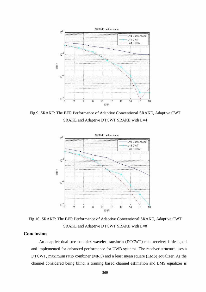
Fig.9. SRAKE: The BER Performance of Adaptive Conventional SRAKE, Adaptive CWT
SRAKE and Adaptive DTCWT SRAKE with L=4
Fig.10. SRAKE: The BER Performance of Adaptive Conventional SRAKE, Adaptive CWT
SRAKE and Adaptive DTCWT SRAKE with L=8
Conclusion
An adaptive dual tree complex wavelet transform (DTCWT) rake receiver is designed
and implemented for enhanced performance for UWB systems. The receiver structure uses a
DTCWT, maximum ratio combiner (MRC) and a least mean square (LMS) equalizer. As the
channel considered being blind, a training based channel estimation and LMS equalizer is

370
implemented and studied. Advantage of using dual tree complex wavelet transform is that
instead of capturing the signal energy in different multipath components at different delays,
it captures them at different frequency components. The proposed scheme does not require
all the parameters of the multipath components, but a short training period is only required to
adjust the tap weights. The performance of the proposed adaptive DTCWT rake receiver is
evaluated and compared with existing conventional adaptive rake receiver and adaptive
continuous wavelet transform rake receiver. It is found that the performance of the proposed
system has shown a significant improvement in average SNR 5-6 dB over the conventional
adaptive rake receiver.
References
1. S.E. El-Khamy, E.F. Badran, A.I. Zaki, UWB analog space time coding systems using a
genetic algorithm based adaptive rake receiver, 2010, Proceedings of the 4th International
Conference on Signal Processing and Communication Systems, Australia, December 2010.
2. J.D. Choi, W.E. Stark, Performance of ultra-wideband communications with suboptimal
receivers in multipath channels, 2002, IEEE Journal on Selected Areas in Communications,
vol. 20, no. 9.
3. I. Oppermann, M. Ha¨ma¨ la¨ inen, J. Iinatti, UWB theory and applications, 2004, England,
John Wiley & Sons, Ltd.
4. B. Mielczarek, M. Wessman, A. Svensson, Performance of coherent UWB rake receivers
with channel estimators, 2003, IEEE 58th, Vehicular Technology Conference, vol. 3.
5. M. Ghavami, L.B. Michael, R. Kohno, Ultra-wideband signals and systems in communication
engineering, 2004, England, John Wiley & Sons, Ltd.
6. M.Z. Win, G. Chrisikos, N.R. Sollenberger, Performance of rake reception in dense multipath
channels: implications of spreading bandwidth and selection diversity order, 2000, IEEE
Journal on Selected Areas in Communications, vol. 18, no. 8.
7. L. Yang, G.B. Giannakis, Analog space–time coding for multi-antenna ultra-wideband
transmissions, 2004, IEEE Transactions on Communications, vol. 52, no. 3.
8. T. Kaiser, F. Zheng, E. Dimitrov, An overview of ultra-wide-band systems with MIMO,
2009, IEEE Proceedings, vol. 97, no. 2.
9. S.E. El-Khamy, E.F. Badran, A.I. Zaki, Interference rejection in UWB systems using smart
STC based on GA rake receivers and TR technique, 2011, Proceedings of the 28th National
Radio Science Conference, NRSC 2011, Cairo, Egypt, March 2011.
371
10. Foerster et al., Channel modeling sub-committee report final, 2003, IEEE P802.15 Wireless
Personal Area Networks, P802.15-02/490rl-SG3a, Feb. 2003.
11. Y. Li, A.F. Molisch, J. Zhang, Channel estimation and signal detection for UWB, 2003,
WPMC, Wireless Personal Multimedia Communications, Oct. 2003.
12. J.D. Choi, W.E. Stark, Performance of ultra-wideband communications with suboptimal
receivers in multi-path channels, 2002, IEEE Journal on Selected Areas in Communications,
vol. 20, pp. 1754-1766.
13. F. Ramirez-Mireles, On the performance of ultra-wideband signals in Gaussian noise and
dense multipath, 2001, IEEE Trans. On Vehicular Technology, vol. 50, no. 1, pp. 244-249.
14. M.K. Lakshmanan, H. Nikookar, A review of wavelets for digital wireless communication,
2006, Journal of Wireless Personal Communications, vol. 37, no. 3.
15. H.M. Oliveira, H.A. Silva, E.A. Bouton, Wavelet shift-keying: A new digital modulation,
2003, XX Simpósio Bras. de Telecomunicações, Rio de Janeiro.
16. F.S. Hassen, The performance of orthogonal wavelet division multiplexing in flat Rayleigh
fading channel, 2008, Journal of Engineering and Development, vol. 12, no. 1.
17. A.H. Kattoush, W.A. Mahmoud, S. Nihad, The performance of multiwavelets based OFDM
system under different channel conditions, 2010, Journal of Digital Signal Processing, vol.
20, no. 2.
18. L.F. Chernogo, O.V. Lasorenko, Application of the wavelet analysis for detecting ultra-
wideband signals in noise, 2000, VIIIth International Conference on Mathematical Methods
in Electromagnetic Theory.
19. L.M. Yu, L.B. White, Design of complex wavelet pulses enabling psk modulation for uwb
impulse radio communications, 2006, Auswireless Conference, 2006.
20. A. Zaki, S. El-khamy, E.F. Badran, A novel rake receiver based on continuous wavelet
transform designed for UWB systems, 2012, European Journal of Scientific Research.
21. Y. Guo, Wavelet packet transform-based time of arrival estimation method for orthogonal
frequency division multiplexing ultra-wideband signal, 2015, IET Sci. Meas. Technol., vol. 9,
pp. 344-350.
22. K. Duncan, K. Mugiira, M. Simon., Optimal rake receiver model utilizing time hopping
impulse response on UWB system, 2016, IJOAR, vol.4, no. 9, pp. 1-15.
Related Documents


![[PPT]Floating Point Analysis - Πανεπιστήμιο Ιωαννίνωνvoippimrc08/present/VoIP_3GPP.ppt · Web viewBoth Rake and Equalizer w/ and w/o receiver diversity at the](https://static.cupdf.com/doc/110x72/5ae9813b7f8b9a8b2b914dd1/pptfloating-point-analysis-voippimrc08presentvoip3gpppptweb.jpg)