Adaptive interference suppression algorithms for DS-UWB systems This thesis is submitted in partial fulfilment of the requirements for Doctor of Philosophy (Ph.D.) Sheng Li Communications Research Group Department of Electronics University of York October 2010

Welcome message from author
This document is posted to help you gain knowledge. Please leave a comment to let me know what you think about it! Share it to your friends and learn new things together.
Transcript
Adaptive interference suppressionalgorithms for DS-UWB systems
This thesis is submitted in partial fulfilment of the requirements forDoctor of Philosophy (Ph.D.)
Sheng LiCommunications Research Group
Department of ElectronicsUniversity of York
October 2010
ABSTRACT
In multiuser ultra-wideband (UWB) systems, a large number of multipath components(MPCs) are introduced by the channel. One of the main challenges for the receiver is toeffectively suppress the interference with affordable complexity. In this thesis, we focuson the linear adaptive interference suppression algorithms for the direct-sequence ultra-wideband (DS-UWB) systems in both time-domain and frequency-domain.
In the time-domain, symbol by symbol transmission multiuser DS-UWB systems areconsidered. We first investigate a generic reduced-rank scheme based on the conceptof joint and iterative optimization (JIO) that jointly optimizes a projection vector anda reduced-rank filter by using the minimum mean-squared error (MMSE) criterion. Alow-complexity scheme, named Switched Approximations of Adaptive Basis Functions(SAABF), is proposed as a modification of the generic scheme, in which the complexityreduction is achieved by using a multi-branch framework to simplify the structure of theprojection vector. Adaptive implementations for the SAABF scheme are developed byusing least-mean squares (LMS) and recursive least-squares (RLS) algorithms. We alsodevelop algorithms for selecting the branch number and the model order of the SAABFscheme. Secondly, a novel linear reduced-rank blind adaptive receiver based on JIO andthe constrained constant modulus (CCM) design criterion is proposed that offers higherspectrum efficiency. Adaptive implementations for the blind JIO receiver are developedby using the normalized stochastic gradient (NSG) and RLS algorithms. In order to obtaina low-complexity scheme, the columns of the projection matrix with the RLS algorithmare updated individually. Blind channel estimation algorithms for both versions (NSGand RLS) are implemented. Assuming the perfect timing, the JIO receiver only requiresthe knowledge of the spreading code of the desired user and the received data.
In the frequency-domain, we propose two adaptive detection schemes based on single-carrier frequency domain equalization (SC-FDE) for the block by block transmission mul-tiuser DS-UWB systems, which are termed structured channel estimation (SCE) and di-rect adaptation (DA). Both schemes use the MMSE linear detection strategy and employa cyclic prefix. In the SCE scheme, we perform the adaptive channel estimation in thefrequency-domain and implement the despreading in the time-domain after the FDE. In

this scheme, the MMSE detection requires the knowledge of the number of users and thenoise variance. For this purpose, we propose low-complexity algorithms for estimatingthese parameters. In the DA scheme, the interference suppression task is fulfilled withonly one adaptive filter in the frequency-domain and a new signal expression is adoptedto simplify the design of such a filter. LMS, RLS and conjugate gradient (CG) adaptivealgorithms are then developed for both schemes.
Another strand of investigation considers adaptive detectors and frequency domainequalization for multiuser DS-UWB systems with block transmissions and biased esti-mation methods. Biased estimation techniques can provide performance improvementsto the existing unbiased estimation algorithms. In this work, biased adaptive estimationtechniques based on shrinkage estimators are devised and incorporated into RLS-type al-gorithms. For the SCE scheme, automatic shrinkage factor mechanisms are proposed andincorporated into RLS estimators, obtaining a lower MSE of the channel estimation. Forthe DA scheme, the automatic shrinkage factors are incorporated directly to the adaptivereceiver weights. The results show that a shorter data support is required by the proposedbiased DA-RLS technique. An analysis of fundamental estimation limits of the proposedfrequency domain biased estimators is included along with the derivation of appropriateCramer-Rao lower bounds (CRLB).

CONTENTS
Acknowledgements . . . . . . . . . . . . . . . . . . . . . . . . . . . . . vii
Declaration . . . . . . . . . . . . . . . . . . . . . . . . . . . . . . . . . viii
Glossary . . . . . . . . . . . . . . . . . . . . . . . . . . . . . . . . . . . ix
List of Symbols . . . . . . . . . . . . . . . . . . . . . . . . . . . . . . . xi
List of Figures . . . . . . . . . . . . . . . . . . . . . . . . . . . . . . . . xi
List of Tables . . . . . . . . . . . . . . . . . . . . . . . . . . . . . . . . xv
1. Introduction . . . . . . . . . . . . . . . . . . . . . . . . . . . . . . . . . . . 1
1.1 UWB Systems . . . . . . . . . . . . . . . . . . . . . . . . . . . . . . . . 1
1.1.1 UWB Pulse-Shaping . . . . . . . . . . . . . . . . . . . . . . . . 2
1.1.2 Spread-Spectrum Techniques in UWB . . . . . . . . . . . . . . . 4
1.1.3 UWB Modulation . . . . . . . . . . . . . . . . . . . . . . . . . 5
1.1.4 UWB Channel Model . . . . . . . . . . . . . . . . . . . . . . . 6
1.2 Adaptive Filtering and Estimation Algorithms . . . . . . . . . . . . . . . 7
1.2.1 The Least-Mean Square Algorithm . . . . . . . . . . . . . . . . 8
1.2.2 The Recursive Least-Squares Algorithm . . . . . . . . . . . . . . 9
1.2.3 Conjugate Gradient Algorithm . . . . . . . . . . . . . . . . . . . 10

1.3 Motivation . . . . . . . . . . . . . . . . . . . . . . . . . . . . . . . . . . 11
1.3.1 Motivation for Time-Domain Signal Processing . . . . . . . . . . 11
1.3.2 Motivation for Frequency-Domain Signal Processing . . . . . . . 13
1.4 Thesis Outline . . . . . . . . . . . . . . . . . . . . . . . . . . . . . . . . 16
1.5 List of Publications . . . . . . . . . . . . . . . . . . . . . . . . . . . . . 16
2. DS-UWB System and Signal Models . . . . . . . . . . . . . . . . . . . . . . 19
2.1 Time-Domain System and Signal Model . . . . . . . . . . . . . . . . . . 19
2.2 Frequency-Domain System and Signal Model . . . . . . . . . . . . . . . 22
3. Reduced-rank Interference Suppression Schemes Based on Joint and Iterative Op-timization and Switching . . . . . . . . . . . . . . . . . . . . . . . . . . . . . 25
3.1 Introduction . . . . . . . . . . . . . . . . . . . . . . . . . . . . . . . . . 25
3.2 Problem Statement . . . . . . . . . . . . . . . . . . . . . . . . . . . . . 26
3.3 Generic Reduced-Rank Scheme and Problem Statement . . . . . . . . . . 27
3.4 Proposed SAABF Scheme and Filter Design . . . . . . . . . . . . . . . . 29
3.4.1 Discrete Parameter Optimization . . . . . . . . . . . . . . . . . . 31
3.4.2 Filter Design . . . . . . . . . . . . . . . . . . . . . . . . . . . . 32
3.5 Adaptive Algorithms . . . . . . . . . . . . . . . . . . . . . . . . . . . . 33
3.5.1 The LMS Version . . . . . . . . . . . . . . . . . . . . . . . . . . 33
3.5.2 The RLS Version . . . . . . . . . . . . . . . . . . . . . . . . . . 35
3.5.3 Complexity Analysis . . . . . . . . . . . . . . . . . . . . . . . . 36

3.6 Model Order and Parameter Adaptation . . . . . . . . . . . . . . . . . . 37
3.6.1 Branch Number Selection . . . . . . . . . . . . . . . . . . . . . 38
3.6.2 Rank Adaptation . . . . . . . . . . . . . . . . . . . . . . . . . . 38
3.6.3 Inner Function Length Selection . . . . . . . . . . . . . . . . . . 39
3.7 Simulations . . . . . . . . . . . . . . . . . . . . . . . . . . . . . . . . . 40
3.8 Conclusions . . . . . . . . . . . . . . . . . . . . . . . . . . . . . . . . . 46
4. Blind Reduced-rank Adaptive Receivers for DS-UWB Systems Based on the JIOand CCM Criterion . . . . . . . . . . . . . . . . . . . . . . . . . . . . . . . 48
4.1 Introduction . . . . . . . . . . . . . . . . . . . . . . . . . . . . . . . . . 48
4.2 Proposed Blind JIO Reduced-Rank Receiver Design . . . . . . . . . . . . 50
4.2.1 Blind JIO Reduced-Rank Receiver . . . . . . . . . . . . . . . . . 50
4.2.2 Blind Channel Estimation . . . . . . . . . . . . . . . . . . . . . 52
4.3 Proposed JIO-NSG Algorithms . . . . . . . . . . . . . . . . . . . . . . . 54
4.3.1 JIO-NSG Algorithms . . . . . . . . . . . . . . . . . . . . . . . . 55
4.3.2 Blind Channel Estimator for the NSG Version . . . . . . . . . . . 58
4.4 Proposed JIO-RLS Algorithms . . . . . . . . . . . . . . . . . . . . . . . 58
4.4.1 JIO-RLS Algorithms . . . . . . . . . . . . . . . . . . . . . . . . 60
4.4.2 Blind Channel Estimator for the RLS version . . . . . . . . . . . 63
4.5 Complexity Analysis and Rank Adaptation Algorithm . . . . . . . . . . . 64
4.5.1 Complexity Analysis . . . . . . . . . . . . . . . . . . . . . . . . 64
4.5.2 Rank Adaptation . . . . . . . . . . . . . . . . . . . . . . . . . . 66
4.6 Simulations . . . . . . . . . . . . . . . . . . . . . . . . . . . . . . . . . 68
4.7 Conclusion . . . . . . . . . . . . . . . . . . . . . . . . . . . . . . . . . 71
5. Frequency Domain Adaptive Detectors for SC-FDE in Multiuser DS-UWB Sys-tems . . . . . . . . . . . . . . . . . . . . . . . . . . . . . . . . . . . . . . . 73
5.1 Introduction . . . . . . . . . . . . . . . . . . . . . . . . . . . . . . . . . 73
5.2 Proposed Linear MMSE Detection Schemes . . . . . . . . . . . . . . . . 74
5.2.1 Problem Statement . . . . . . . . . . . . . . . . . . . . . . . . . 75
5.2.2 Detector with Structured Channel Estimation (SCE) . . . . . . . 76
5.2.3 Detector with Direct Adaptation (DA) . . . . . . . . . . . . . . . 77
5.3 Adaptive Algorithms for SCE . . . . . . . . . . . . . . . . . . . . . . . . 80
5.3.1 SCE-LMS . . . . . . . . . . . . . . . . . . . . . . . . . . . . . . 80
5.3.2 SCE-RLS . . . . . . . . . . . . . . . . . . . . . . . . . . . . . . 81
5.3.3 SCE-CG . . . . . . . . . . . . . . . . . . . . . . . . . . . . . . 82
5.4 Adaptive Algorithms for DA . . . . . . . . . . . . . . . . . . . . . . . . 83
5.4.1 DA-LMS . . . . . . . . . . . . . . . . . . . . . . . . . . . . . . 83
5.4.2 DA-RLS . . . . . . . . . . . . . . . . . . . . . . . . . . . . . . 85
5.4.3 DA-CG . . . . . . . . . . . . . . . . . . . . . . . . . . . . . . . 87
5.5 Complexity Analysis . . . . . . . . . . . . . . . . . . . . . . . . . . . . 88
5.6 Noise Variance and Number of Active Users Estimation . . . . . . . . . . 89

5.6.1 Noise Variance Estimation . . . . . . . . . . . . . . . . . . . . . 91
5.6.2 Number of Active Users Estimation . . . . . . . . . . . . . . . . 92
5.7 Simulation Results . . . . . . . . . . . . . . . . . . . . . . . . . . . . . 93
5.8 Conclusion . . . . . . . . . . . . . . . . . . . . . . . . . . . . . . . . . 98
6. Adaptive Parameter Estimation and Interference Suppression with Bias in the Fre-quency Domain . . . . . . . . . . . . . . . . . . . . . . . . . . . . . . . . . 100
6.1 Introduction . . . . . . . . . . . . . . . . . . . . . . . . . . . . . . . . . 100
6.2 Parameter Estimation . . . . . . . . . . . . . . . . . . . . . . . . . . . . 103
6.2.1 LS solution Parameter Estimation . . . . . . . . . . . . . . . . . 103
6.2.2 Shrinkage Factor Estimation in Parameter Estimation . . . . . . . 104
6.3 Interference Suppression . . . . . . . . . . . . . . . . . . . . . . . . . . 107
6.3.1 LS Solution for Interference Suppression . . . . . . . . . . . . . 107
6.3.2 Shrinkage Factor Estimation in Interference Suppression Schemes 109
6.4 The Cramer-Rao Lower Bound and Its Extension . . . . . . . . . . . . . 112
6.5 Simulations . . . . . . . . . . . . . . . . . . . . . . . . . . . . . . . . . 114
6.6 Conclusion . . . . . . . . . . . . . . . . . . . . . . . . . . . . . . . . . 119
7. Conclusions and Future Work . . . . . . . . . . . . . . . . . . . . . . . . . . 121
7.1 Summary of Work . . . . . . . . . . . . . . . . . . . . . . . . . . . . . . 121
7.2 Future Work . . . . . . . . . . . . . . . . . . . . . . . . . . . . . . . . . 123

Appendix 125
A. Proof of the Equivalence of the Schemes . . . . . . . . . . . . . . . . . . . . 126
B. Analysis of the Optimization Problem . . . . . . . . . . . . . . . . . . . . . . 128
C. Convergence Properties for the CCM Function . . . . . . . . . . . . . . . . . 130
Bibliography . . . . . . . . . . . . . . . . . . . . . . . . . . . . . . . . . . . 131

Acknowledgements
Firstly, I would like to express my most sincere gratitude to my supervisor, Dr. RodrigoC. de Lamare, for his help and valuable supervision with my research, without whichmuch of this work would not have been possible.
Further thanks go to all members of the Communications Research Group, for theirsupport throughout my Ph.D. research.
Finally, my deep gratitude goes to my parents and my wife Xiaolei Zhang for theirunconditional support, end-less love and encouragement.
Sheng Li, Ph.D. Thesis, Department of Electronics, University of Yorkvii
2010

Declaration
Some of the research presented in this thesis has resulted in some publications. Thesepublications are listed at the end of Chapter 1.
All work presented in this thesis as original is so, to the best knowledge of the author.References and acknowledgements to other researchers have been given as appropriate.
Sheng Li, Ph.D. Thesis, Department of Electronics, University of Yorkviii
2010

Glossary
ADC Analog-to-Digital ConvertersAT Automatic TuningAVF Auxiliary Vector FilteringAWGN Additive White Gaussian NoiseBCG Block Conjugate GradientBER Bit Error RateBOK Bi-Orthogonal Keying (4BOK)BPAM Binary Pulse Amplitude ModulationBPSK Binary Phase Shift KeyingCCM Constrained Constant ModulusCDMA Code-Division Multiple AccessCG Conjugate GradientCM Constant ModulusCMF Chip-Matched FilterCMV Constrained Minimum VarianceCP Cyclic-PrefixedCRLB Cramer-Rao Lower BoundDA Direct AdaptationDFT Discrete Fourier TransformDS-UWB Direct-sequence Ultra-widebandEB Estimator BasedFCC Federal Communications CommissionFIR Finite Impulse ResponseFR Full-RankGPS Global Positioning SystemIBI Inter Block InterferenceISI Inter-symbol InterferenceJIO Joint Iterative OptimizationLDPC Low-Density Parity-CheckLMS Least-mean SquaresLS Least SquaresMAI Multiple Access InterferenceML Maximum LikelihoodMMSE Minimum Mean-squared ErrorMPCs Multipath ComponentsMSE Mean-squared ErrorMSWF Multistage Wiener Filter
Sheng Li, Ph.D. Thesis, Department of Electronics, University of Yorkix
2010

MVUE Minimum Variance Unbiased EstimatorNBI Narrow Band InterferenceNLOS Non-line of SightNSG Normalized Stochastic GradientOFDM Orthogonal Frequency-Division MultiplexingOOK On-Off KeyingPC Principle ComponentPPM Pulse Position ModulationPSM Pulse shape modulationRLS Recursive Least SquaresRR Reduced-RankRRC Root-Raised CosineSAABF Switched Approximations of Adaptive Basis FunctionsSCE Structured Channel EstimationSC-FDE Single-carrier Frequency Domain EqualizationSG Stochastic GradientSINR Signal-plus-Interference-to-Noise RatioSIR Signal-to-Interference RatioSNR Signal-to-Noise RatioSVD Singular Value DecompositionTH-UWB Time-hopping UWBUFZ UWB Friendly ZoneUWB Ultra-widebandWPANs Wireless Personal Area Networks

List of Symbols
∇ GradientO(·) ComplexityE[·] Expectation∞ InfinityR(·) Real partC(·) Imaginary partΠ Product∑
Sum‖ · ‖ Euclidean norm| · | Absolutediag(a) A diagonal matrix with the diagonal vector equals to a
trace(·) Trace of a matrixI Identity matrixspan(·) Span a spaceCm×q space of complex valued matrices of size m by q
Rm×q space of real valued matrices of size m by q
Sheng Li, Ph.D. Thesis, Department of Electronics, University of Yorkxi
2010

LIST OF FIGURES
1.1 Typical UWB waveforms . . . . . . . . . . . . . . . . . . . . . . . . . . 2
1.2 Time window of transmitted data bit ’1’ in a BPSK DS-UWB system. . . 3
1.3 Time window of transmitted data bits in a BPSK TH-UWB system. . . . 4
1.4 UWB modulation schemes . . . . . . . . . . . . . . . . . . . . . . . . . 5
1.5 One realization of the IEEE 8020.15.4a channel model . . . . . . . . . . 7
2.1 Block diagram of the time-domain system model. . . . . . . . . . . . . . 19
2.2 Block diagram of the frequency-domain system model. . . . . . . . . . . 23
3.1 Block diagram of the proposed reduced-rank linear receiver using theSAABF scheme. . . . . . . . . . . . . . . . . . . . . . . . . . . . . . . 29
3.2 The computational complexity of the linear adaptive algorithms. . . . . . 37
3.3 BER performance of different algorithms for a SNR=20dB and 8 users.The following parameters were used: full-rank LMS (µ = 0.075), full-rank RLS (λ = 0.998, δ = 10), MSWF-LMS (D = 6, µ = 0.075),MSWF-RLS (D = 6, λ = 0.998), AVF (D = 6), SAABF (1,3,M)-LMS (µw = 0.15, µψ = 0.15, 3 iterations) and SAABF (1,3,M)-RLS(λ = 0.998, δ = 10, 3 iterations). . . . . . . . . . . . . . . . . . . . . . . 41
3.4 BER performance of the proposed SAABF scheme versus the numberof training symbols for a SNR=20dB. The number of users is 8 and thefollowing parameters were used: SAABF-RLS (λ = 0.998, δ = 10). . . . 42

3.5 BER performance of the proposed scheme with different SNRs and num-ber of users. . . . . . . . . . . . . . . . . . . . . . . . . . . . . . . . . . 43
3.6 BER performance of the SAABF scheme with branch-number selection.The scenario of 20dB and 8 users are considered. The parameters used:SAABF-RLS (λ = 0.998, δ = 10). For branch-number selection algo-rithm: Cmin = 6 and Cmax = 12, threshold γ is in the unit of dB. . . . . . 44
3.7 BER performance of the SAABF scheme with rank adaptation. The sce-nario of 16dB and 8 users are considered. The parameters used: SAABF-LMS (µw = 0.15, µψ = 0.15). For rank-adaptation algorithm: Dmin = 3,Dmax = 8 and λD = 0.998. . . . . . . . . . . . . . . . . . . . . . . . . . 45
3.8 BER performance of the SAABF scheme with adaptive short functionlength. The scenario of 16dB and 8 users are considered. The parametersused: SAABF-RLS (λ = 0.998, δ = 10). qmin = 3, qmax = 8 andλq = 0.998. . . . . . . . . . . . . . . . . . . . . . . . . . . . . . . . . . 46
3.9 BER performance against SNR of different receiver structures in a systemwith 8 users. . . . . . . . . . . . . . . . . . . . . . . . . . . . . . . . . . 47
4.1 Block diagram of the proposed blind reduced-rank receiver. . . . . . . . . 50
4.2 Number of multiplications required for different blind algorithms. . . . . 66
4.3 Number of multiplications required for BCEs. . . . . . . . . . . . . . . . 67
4.4 BER performance of different algorithms. For full-rank NSG: µ = 0.025,full-rank RLS: δ = 10, λ = 0.9998. For MSWF-NSG, D = 6, µ = 0.025;MSWF-RLS: D = 8, λ = 0.998. For JIO-NSG D = 4, cmax = 3, � = 1,µT,0 = 0.075, µw,0 = 0.005; JIO-RLS: D = 3, λ = 0.9998, δ = 10,� = 0.5. . . . . . . . . . . . . . . . . . . . . . . . . . . . . . . . . . . . 69
4.5 BER performance of the proposed JIO-CCM scheme with different SNRs. 70
4.6 BER performance of the proposed JIO-CCM scheme with different num-ber of users. . . . . . . . . . . . . . . . . . . . . . . . . . . . . . . . . . 71
4.7 BER performance of the rank-adaptation algorithm in JIO-CCM scheme. 72

4.8 BER performance of the blind adaptive algorithm with NBI. For NBI,fd = 23MHz. . . . . . . . . . . . . . . . . . . . . . . . . . . . . . . . . 72
5.1 Block diagram of SC-FDE schemes in DS-UWB system, (a) Structuredchannel estimation (SCE) and (b) Direct adaptation (DA). . . . . . . . . . 74
5.2 Complexity comparison of the proposed schemes for SC-FDE. . . . . . . 90
5.3 BER performance of the proposed SC-FDE detection schemes versus thenumber of training blocks for a SNR=16dB. The number of users is 3. . . 94
5.4 Performance of the noise variance estimator. . . . . . . . . . . . . . . . . 95
5.5 Performance of the active users number estimator. . . . . . . . . . . . . . 96
5.6 BER performance of the proposed CG algorithms versus the number oftraining blocks for a SNR=16dB. The number of users is 3. . . . . . . . . 97
5.7 BER performance of the proposed SC-FDE detection schemes versus theSNR. The number of users is 3. . . . . . . . . . . . . . . . . . . . . . . . 98
5.8 BER performance of the proposed SC-FDE detection schemes versusnumber of Users in the scenario with a 16dB SNR. . . . . . . . . . . . . 99
6.1 MSE performance (‖h− h‖2) of the biased structured channel estimation(SCE). The parameters used: RLS (λ = 0.998, δ = 10). Proposed EB:µ = 0.075 and proposed AT: µ = 0.075, µp = 0.05, Pm,min = 0.05,Pm,max = 0.15. . . . . . . . . . . . . . . . . . . . . . . . . . . . . . . . 114
6.2 MSE performance (‖h− h‖2) of the biased SCE with different SNRs. . . 115
6.3 MSE performance (‖h − h‖2) of the biased SCE with different numberof users. . . . . . . . . . . . . . . . . . . . . . . . . . . . . . . . . . . . 116
6.4 MSE performance (‖b− b‖2) of the biased estimator in DA-RLS schemewith 3users in 3dB SNR. The parameters used: RLS (λ = 0.998, δ = 2).Proposed EB: µ = 0.0075 and proposed AT: µ = 0.0075, µp = 0.005,Pm,min = 10, Pm,max = 20. . . . . . . . . . . . . . . . . . . . . . . . . . 117

6.5 MSE performance (‖b−b‖2) of the biased estimator in short data supportDA-RLS scheme with 3users in a scenario with SNR=3dB. . . . . . . . . 118
6.6 MSE performance (‖b− b‖2) of the biased estimator in DA-RLS schemewith 3users in a scenario with SNR=10dB. . . . . . . . . . . . . . . . . . 119
6.7 BER performance in SCE scheme with different SNRs in a 3 user scenario. 120

LIST OF TABLES
3.1 Proposed adaptive algorithms for SAABF scheme. . . . . . . . . . . . . 34
3.2 Complexity analysis for the MMSE based algorithms . . . . . . . . . . . 36
4.1 NSG version of the Proposed JIO-CCM Receiver. . . . . . . . . . . . . . 59
4.2 RLS version of the Proposed JIO-CCM Receiver. . . . . . . . . . . . . . 63
4.3 Complexity analysis for the blind algorithms . . . . . . . . . . . . . . . . 65
5.1 Adaptive Algorithms For The Proposed Frequency domain DetectionSchemes . . . . . . . . . . . . . . . . . . . . . . . . . . . . . . . . . . . 84
5.2 Complexity analysis for the frequency domain adaptive algorithms . . . . 88
6.1 Biased Estimation for SCE-RLS in SC-FDE DS-UWB Systems . . . . . 107
6.2 Biased Estimation for DA-RLS in SC-FDE DS-UWB Systems . . . . . . 111

1. INTRODUCTION
Contents1.1 UWB Systems . . . . . . . . . . . . . . . . . . . . . . . . . . . . . . 1
1.2 Adaptive Filtering and Estimation Algorithms . . . . . . . . . . . . 7
1.3 Motivation . . . . . . . . . . . . . . . . . . . . . . . . . . . . . . . . 11
1.4 Thesis Outline . . . . . . . . . . . . . . . . . . . . . . . . . . . . . . 16
1.5 List of Publications . . . . . . . . . . . . . . . . . . . . . . . . . . . 16
1.1 UWB Systems
Ultra-wideband (UWB) technology is a promising short-range wireless communica-tion technique. The research on impulse radio by Win and Scholtz [1]- [3], has placedUWB as a potentially very fast communication scheme. In 2002, the Federal Commu-nications Commission (FCC) in the US release a 7.5GHz (3.1GHz − 10.6GHz) hugebandwidth for unlicensed use of UWB systems [4]- [10]. This permit boosts the develop-ment of the UWB communications for commercial applications. Using extremely shortpulses, UWB can be considered as a multipath immunity communication. This is becausethe multipath components (MPCs) in UWB systems whose path lengths differ by onlya few centimeters, e.g., 10 cm for a signal bandwidth of 3 GHz, are resolvable at thereceiver [10], [11].
The advantages of UWB systems on the aspect of engineering can be summarized byexamining Shannon’s capacity equation as shown in [6]- [10]. The channel capacity ofcommunications systems can be improved by increasing the channel bandwidth or thesignal to noise ratio (SNR). With the huge bandwidth, UWB communications could havehigh capacity of the channel. Another way to summarize the benefits of UWB is to con-sider the degree of diversity at the receiver [9]. For UWB systems, the huge transmissionbandwidths introduce a large number of resolvable MPCs at the receiver, and hence, ahigh degree of diversity is available [11]. Receivers for UWB systems are required to

2
efficiently suppress the severe inter-symbol interference (ISI) that is caused by the densemultipath channel and the multiple-access interference (MAI) that is caused by the lackof orthogonality between signals at the receiver in multiuser communications.
In this section, some basic aspects of the UWB systems are introduced. Parametersand the technologies that are adopted in our system model are presented and discussed.
1.1.1 UWB Pulse-Shaping
−0.2 −0.1 0 0.1 0.2
0
0.2
0.4
0.6
0.8
1Gaussian
Time [ns]
Am
plitu
de
−0.2 −0.1 0 0.1 0.2−1
−0.5
0
0.5
1Gaussian Monocycle
Time [ns]
Am
plitu
de
−0.2 −0.1 0 0.1 0.2−0.5
0
0.5
1Gaussian doublet
Time [ns]
Am
plitu
de
−0.2 −0.1 0 0.1 0.2−0.2
0
0.2
0.4
0.6
0.8
RRC
Time [ns]
Am
plitu
de
Fig. 1.1: Typical UWB waveforms
The extremely short pulses make the UWB a unique technique, the pulse shaping is animportant aspect of designing a UWB communication systems. In the document [4], theUWB signal has been described with the following characteristics: the maximum trans-mission power is −41.3dBm/MHz; the minimum −10dB bandwidth is 500MHz andthe power level beyond −20dB bandwidth must at least 20dB lower than the maximumtransmission power.
It should be noted that due to the pressure from other wireless groups such as the
Sheng Li, Ph.D. Thesis, Department of Electronics, University of York 2010

3
global positioning system (GPS), the allowed maximum power level −41.3dBm/MHz
is a conservative limitation [10]. For example, in the UWB Friendly Zone (UFZ) ofSingapore, the maximum power level allowed is −35.3dB/MHz [7].
A typical class of UWB pulses is the Gaussian waveforms which consist of the Gaus-sian pulse, the Gaussian monocycle and the Gaussian doublet [10]. Another class ofpulse shaping technology that is widely used is the raised-cosine pulse shaping and theroot-raised cosine (RRC) pulse shaping [7], [12]. The traditional rectangular waveformwhich is used for code-division multiple access (CDMA) systems cannot be adopted forUWB systems since the power level of the sidelobe of this kind of pulse is too high. In thisthesis, the pulse waveform is modeled as the RRC pulse with a roll-off factor of 0.5 [12].Fig.1.1 shows the Gaussian waveforms and the RRC waveform. The main advantage ofthese typical UWB pulses is that they can be generated easily [10], the main drawback ofthem is the poor fitness of the spectral mask [14].
The design of orthogonal waveforms have been described in [10] and some new wave-forms that can fit the FCC spectral mask have been proposed in [13] and [14]. Thesewaveforms could improve the performance of the UWB communications. However, theadoption of these technologies will increase the complexity of the hardware design.
0 1 2 3 4 5 6 7 8 9 10−1
−0.8
−0.6
−0.4
−0.2
0
0.2
0.4
0.6
0.8
1
Time [ns]
Am
plitu
de
DS−UWB symbol (BPSK, Databit ’’1’’), Nc=10, Tc=1ns, Gaussian waveform
Fig. 1.2: Time window of transmitted data bit ’1’ in a BPSK DS-UWB system.
Sheng Li, Ph.D. Thesis, Department of Electronics, University of York 2010

4
0 2 4 6 8 10−1
−0.8
−0.6
−0.4
−0.2
0
0.2
0.4
0.6
0.8
1
Time [ns]
Am
plitu
de
TH−UWB (BPSK), Nf=5, T
f=2ns, Tc=1ns, Gaussian waveform
Data bit ’’1’’Data bit ’’0’’
Fig. 1.3: Time window of transmitted data bits in a BPSK TH-UWB system.
1.1.2 Spread-Spectrum Techniques in UWB
There are two popular spread-spectrum techniques in UWB communications, namelyDirect-sequence UWB (DS-UWB) and Time-hopping UWB (TH-UWB) [6]. In the DS-UWB system, the information symbols are spread by a pseudo-random (PR) code and thepulses are transmitted continuously [6]. In Fig.1.2, the transmitted data bit ’1’ in a BPSKDS-UWB system is presented. The spreading code is s = [1, 1,−1,−1, 1,−1, 1, 1,−1, 1]
and the spreading gain equals to 10. The TH-UWB uses a PR code to define the pulsetransmitting time [3]. In Fig. 1.3, the transmitted data bits in a BPSK TH-UWB systemare presented. In this example, the number of frames is set to 5 and the number of chips ineach frame is set to 2. The spreading gain equals to 10 which is the same as the examplein Fig. 1.2.
The TH-UWB has been chosen for low-data rate applications such as ranging andlocalization [15]. Due to the sensitiveness of the synchronization in TH-UWB system,DS-UWB performs better for high-speed indoor links [16]. In 2005, direct-sequence DS-UWB was proposed as a possible standard physical layer technology for wireless personalarea networks (WPANs) and it has the potential to provide high data rates ranging from
Sheng Li, Ph.D. Thesis, Department of Electronics, University of York 2010
5
28Mbps to 1.32Gbps [12], [17]. In this thesis, the target operate environment is assumedto be non-line of sight (NLOS) indoor links with high data rate, so the DS-UWB systemis adopted. We remark that the adaptive receivers proposed in this thesis are generalschemes, which means they can work not only in the DS-UWB systems, but also in theTH-UWB systems and other wireless communication systems.
1.1.3 UWB Modulation
−0.2 −0.1 0 0.1 0.2−1
−0.5
0
0.5
1BPAM
Time [ns]
Am
plitu
de
Bit 1Bit 0
−0.2 −0.1 0 0.1 0.2−0.2
0
0.2
0.4
0.6
0.8
OOK
Time [ns]
Am
plitu
de
−0.2 −0.1 0 0.1 0.2−0.2
0
0.2
0.4
0.6
0.8
PPM
Time [ns]
Am
plitu
de
−0.2 −0.1 0 0.1 0.2−1
−0.5
0
0.5
1PSM
Time [ns]
Am
plitu
de
Fig. 1.4: UWB modulation schemes
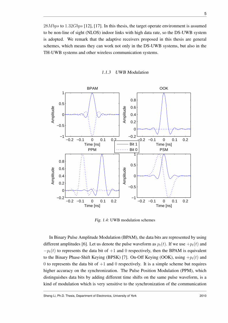
In Binary Pulse Amplitude Modulation (BPAM), the data bits are represented by usingdifferent amplitudes [6]. Let us denote the pulse waveform as pt(t). If we use +pt(t) and−pt(t) to represents the data bit of +1 and 0 respectively, then the BPAM is equivalentto the Binary Phase-Shift Keying (BPSK) [7]. On-Off Keying (OOK), using +pt(t) and0 to represents the data bit of +1 and 0 respectively. It is a simple scheme but requireshigher accuracy on the synchronization. The Pulse Position Modulation (PPM), whichdistinguishes data bits by adding different time shifts on the same pulse waveform, is akind of modulation which is very sensitive to the synchronization of the communication
Sheng Li, Ph.D. Thesis, Department of Electronics, University of York 2010

6
systems. The Pulse shape modulation (PSM) uses different waveforms to presents differ-ent data bits. This scheme require more than one pulse generater and hence has highercomplexity.
The pulse shapes for these four typical data modulation schemes are shown in Fig.1.4[6]. It should be noted that these schemes could change to M-ary modulation schemesto improve power efficiency or increase the data rate, but the systems complexity willbecome higher. The comparison of performance of BPAM, OOK and PPM in AWGNchannel in presence of jamming is shown in [18], where BPAM outperforms OOK andPPM in both TH-UWB and DS-UWB systems. In [19], BPAM (or BPSK) is preferred forits high power efficiency and smooth spectrum. It should be noted that as required in [12],the high data rate of the DS-UWB systems is achieved with BPSK and 4-ary bi-orthogonalkeying (4BOK) modulation. All the compliant devices of DS-UWB communicationsmust support BPSK modulation, while the 4BOK modulation scheme is optional [17]. Inthis thesis, we will focus on the BPSK modulation.
1.1.4 UWB Channel Model
The first work on statistical UWB channel models came out in 2001 [20], [21], and thestandardized channel models of IEEE 802.15.3a and 802.15.4a groups were developed in2003 and 2005, respectively [22], [23].
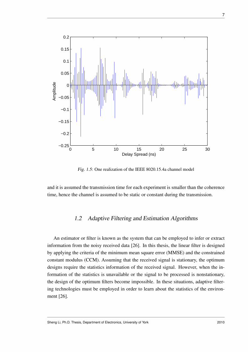
The standard channel model developed by the IEEE 802.15.3a group was the firststandard model for UWB communications. However, this model only considered theoffice and residential indoor environments with a range of less than 10m [25]. With moremeasurements, a more general standard channel model was determined by the 802.15.4agroup [24]. The 4a model was proposed for UWB systems in more operate environmentssuch as office indoor, residential indoor, industrial, outdoor, and farm environments [23].It should be noted that the IEEE 802.15.4a group was established to recognize some low(< 1Mbps) data rates applications such as the UWB sensor networks, but the 4a standardchannel model is valid for UWB systems irrespective of the data rate and the modulationformat [25]. In this thesis, we adopt the more flexible IEEE 802.15.4a standard channelmodel for the indoor residential non-line of sight (NLOS) environment. An examplerealization of the 4a channel model is shown in Fig 1.5. This realization is adopted inChapter 3 for the desired user. It should be noted that for a wireless communicationsystem, the channel changes as a function of time and frequency. Coherence time andcoherence bandwidth indicate how quickly the channel changes in time and frequency,respectively [9]. In this thesis, the focus is on the development of the adaptive algorithms
Sheng Li, Ph.D. Thesis, Department of Electronics, University of York 2010
7
0 5 10 15 20 25 30−0.25
−0.2
−0.15
−0.1
−0.05
0
0.05
0.1
0.15
0.2
Delay Spread (ns)
Am
plitu
de
Fig. 1.5: One realization of the IEEE 8020.15.4a channel model
and it is assumed the transmission time for each experiment is smaller than the coherencetime, hence the channel is assumed to be static or constant during the transmission.
1.2 Adaptive Filtering and Estimation Algorithms
An estimator or filter is known as the system that can be employed to infer or extractinformation from the noisy received data [26]. In this thesis, the linear filter is designedby applying the criteria of the minimum mean square error (MMSE) and the constrainedconstant modulus (CCM). Assuming that the received signal is stationary, the optimumdesigns require the statistics information of the received signal. However, when the in-formation of the statistics is unavailable or the signal to be processed is nonstationary,the design of the optimum filters become impossible. In these situations, adaptive filter-ing technologies must be employed in order to learn about the statistics of the environ-ment [26].
Sheng Li, Ph.D. Thesis, Department of Electronics, University of York 2010

8
In this section, the MMSE design criterion based adaptive algorithms such as the least-mean square (LMS), recursive least-squares (RLS) and the conjugate gradient (CG) areintroduced.
1.2.1 The Least-Mean Square Algorithm
The major advantage of the LMS algorithm is its simplicity and this feature makes theLMS as a standard against other linear adaptive algorithms [26]. The LMS algorithm canbe developed from the MSE cost function:
JMSE = E[|e(i)|2], (1.1)
where the error signal e(i) equals to the difference between the desired signal d(i) andthe output signal is y(i). The output signal y(i) = wH(i)r(i), where w(i) is the filterrepresented by a M -by-1 weight vector and r(i) is the M -by-1 received signal. Thegradient vector of JMSE with respect to w(i) can be expressed as:
g(i) = −p + Rw(i), (1.2)
where R = E[r(i)rH(i)] is the correlation matrix of the received signal and p =
E[r(i)d∗(i)] is the cross-correlation vector between the received signal and the desiredsignal. The optimum solution of such a linear filter is known as the Wiener solution thatis given by
wo = R−1p. (1.3)
Since R and p are statistics of the received signal and are not given for the adaptivealgorithms, these information must be estimated. LMS algorithms adopt the simplestestimator that use the instantaneous estimates for R and p [26], which can be expressedmathematically as R(i) = r(i)rH(i) and p(i) = r(i)d∗(i). The basic idea behind theLMS adaptive method is to approach the optimum filter solution by adjusting the filterweight vector in the direction of the inverse of the gradient vector. Hence, the adaptationof weight vector of LMS can be expressed as
w(i + 1) = w(i) + µ(−g(i)) = w(i) + µ(−p(i) + R(i)w(i))
= w(i) + µr(i)[d∗(i)− rH(i)w(i)] = w(i) + µr(i)e∗(i),(1.4)
where µ is known as the step-size parameter. A necessary and sufficient condition for the
Sheng Li, Ph.D. Thesis, Department of Electronics, University of York 2010

9
convergence of the LMS algorithms is given in [26] as:
0 < µ <2
MSmax
, (1.5)
where M is the length of the filter and Smax is the maximum value of the power spectraldensity (PSD) of the received vector. The complexity of the LMS algorithm is O(M).
1.2.2 The Recursive Least-Squares Algorithm
The advantage of the RLS algorithms is its faster convergence rate than the LMS algo-rithms. However, the RLS algorithms have higher computational complexity. The RLSalgorithms use a recursive strategy to compute the LS estimators for the correlation matrixR and the cross-correlation vector p, and adopt the matrix inversion lemma to computethe inverse of the estimate of correlation matrix.
We can develop a RLS adaptive algorithm via the cost function:
JLS =i∑
j=1
λi−j|d(i)−wH(i)r(i)|2,
where w(i) is the filter represented by a M -by-1 weight vector and r(i) is the M -by-1received signal. The forgetting factor λ is a positive constant which is smaller but closeto 1 [26]. The optimum LS solution of the filter weight vector is
wLS(i) = R−1rls(i)prls(i), (1.6)
where Rrls(i) =∑i
j=1 λi−jr(j)rH(j) and prls(i) =∑i
j=1 λi−jd∗(j)r(j). We use the ma-trix inversion lemma to computer the term of R−1
rls(i) and obtain an recursive expressionfor the filter weight vector. The adaption equations of RLS algorithms are summarized asfollows:
Mrls(i) = R−1rls(i− 1)r(i),
Krls(i) =Mrls(i)
λ + rH(i)Mrls(i),
e(i) = d(i)−wH(i− 1)r(i),
w(i) = w(i− 1) + Krls(i)e∗(i),
R−1rls(i) =
R−1rls(i− 1)−Krls(i)r
H(i)R−1rls(i− 1)
λ.
Sheng Li, Ph.D. Thesis, Department of Electronics, University of York 2010

10
The complexity of the RLS algorithm is O(M2).
1.2.3 Conjugate Gradient Algorithm
The conjugate gradient (CG) algorithm is well known for its faster convergence ratethan the LMS algorithm and lower computational complexity than the RLS algorithm [27]- [31]. For the adaptive filtering technique, the CG algorithm is developed to solve theproblem
Rw = p, (1.7)
where R is the M -by-M correlation matrix of the received signal and p is the M -by-1 cross-correlation vector. The CG algorithm provide an iterative way to calculate w
without inverting R. The basic CG algorithm can be expressed as follows [29], [31] bydefining c as the index of the iterations
Initialization:
w0 = 0 ; d0 = g0 = p ; ρ0 = gH0 g0.
For c = 1, 2, . . . , cmax
αc = ρc−1/dHc Rdc,
wc = wc−1 + αcdc,
gc = gc−1 − αcRdc,
ρc = gHc gc,
βc = ρc/ρc−1,
dc+1 = gc + βcdc,
c = c + 1.
End
w = wcmax ,
where αc is the step size that minimizes the cost function (1.1), dc is the direction vectorsand gc is defined as the inverse of the gradient vector of the cost function with respect tow.
Sheng Li, Ph.D. Thesis, Department of Electronics, University of York 2010

11
The adaptive CG algorithms require several iterations for each input data vector, but theadaptation time approaches 1 as the index of data vector increases [28]. The CG adaptivealgorithm can also be used in block-by-block transmission systems. Assuming that a setof linearly independent direction vectors d0,d1, . . . ,dN−1 is given, where N is the blocklength. And these vectors are mutually conjugate with respect to the correlation matrix R
[28], that means the scalar term of dHi Rdj is larger than zero only in the case when i = j,
otherwise the value of this term is 0. For each iteration, the filter weight vector is adaptedalong the corresponding direction vector and the convergence can be obtained with at mostN iterations [27]. The complexity of the CG algorithm is O(M2). Note that although thecomplexity is at the same level as the RLS algorithm, the number of operations measuredin terms of arithmetic of the CG algorithm is lower than the traditional RLS algorithm[29].
1.3 Motivation
In UWB communications, the major challenges include the interference mitigation,synchronization and network design [6]- [8]. In this thesis, we focus on the linear adap-tive solutions for the interference mitigation problem in multiuser DS-UWB systems. Intime-domain symbol by symbol transmission systems, novel reduced-rank receivers areproposed. We also develop the adaptive receivers for single-carrier frequency domainequalization (SC-FDE) in the block by block transmission systems. It should be notedthat the techniques developed for SC-FDE can also be used for multiband UWB systemsthat are based on orthogonal frequency-division multiplexing (OFDM) [67].
1.3.1 Motivation for Time-Domain Signal Processing
For DS-UWB communications, the major challenge for the adaptive interference sup-pression schemes is to achieve the robustness against narrow band interference and obtainfast convergence with satisfactory steady state performance in dense-multipath environ-ments. Due to the long channel delay spread in UWB systems, the received signal lengthis large and the interference sensitive full-rank adaptive schemes experience slow con-vergence rate and are subject to significant performance degradation in the presence ofinterference that can be of various types, namely, multiple access interference (MAI),inter-symbol interference (ISI) and narrow band interference (NBI). Reduced-rank algo-rithms can be adopted to accelerate the convergence and provide an increased robustnessagainst interference and noise. Recently, reduced-rank schemes have been considered
Sheng Li, Ph.D. Thesis, Department of Electronics, University of York 2010

12
for UWB systems in [32]- [37]. A reduced-order finger selection linear MMSE receiverwith RAKE-based structures have been proposed in [32], which requires the knowledgeof the channel and the noise variance. Solutions for reduced-rank channel estimation andsynchronization in single-user UWB systems have been proposed in [33]. For multiuserdetection in UWB communications, reduced-rank schemes have been developed in [34]-[36] requiring knowledge of the multipath channel. In [37], the reduced-rank multiuserdetector is proposed for hybrid direct-sequence time-hopping ultrawide bandwidth (DS-TH UWB) systems. The reduced-rank filtering techniques have faster convergence andincreased robustness than the full-rank algorithms [38]- [51]. The well-known reduced-rank techniques include the eigen-decomposition methods such as the principal compo-nents (PC) [40] and the cross-spectral metric (CSM) [41], the Krylov subspace methodssuch as the powers of R (POR) [39], the multistage Wiener filter (MSWF) [42], [44] andthe auxiliary vector filtering (AVF) [46]. Eigen-decomposition methods are based on theeigen-decomposition of the estimated covariance matrix of the received signal. The op-timal representation of the input data can be obtained by the eigen-decomposition of thecovariance matrix R [44]. However, R is unknown and must be estimated. In addition,these methods have very high computational complexity and the performance is oftenpoor in heavily loaded communication systems [42]. Compared with the full-rank linearfiltering techniques, the MSWF and AVF methods have faster convergence speed with amuch smaller filter size. However, their computational complexity is still very high. InChapter 3, we firstly investigate a generic reduced-rank scheme with joint and iterativeoptimization (JIO) of a projection vector and a reduced-rank linear estimator to minimizethe MSE cost function. Since information is exchanged between the projection vector andthe reduced-rank filter for each adaptation, this generic scheme outperforms other exist-ing reduced-rank schemes. However, in this generic scheme, a large projection vector isrequired to be updated for each time instant and hence introduces high complexity. Inorder to obtain a low-complexity configuration of the generic scheme and maintain theperformance, we propose the novel switched approximation of adaptive basis functions(SAABF) scheme. The basic idea of the SAABF scheme is to simplify the design of theprojection vector by using a multiple-branch framework such that the number of coeffi-cients to be adapted in the projection vector is reduced and hence achieve the complexityreduction. The LMS and RLS adaptive algorithms are then developed for the joint adap-tation of the shortened projection vector and the reduced-rank filter. We also proposeadaptive algorithms for branch number selection and model order adaptation.
Blind adaptive linear receivers [52]- [58] are efficient schemes for interference sup-pression as they offer higher spectrum efficiency than the adaptive schemes that require atraining stage. Low complexity blind receiver designs can be obtained by solving con-strained optimization problems based on the constrained constant modulus (CCM) or
Sheng Li, Ph.D. Thesis, Department of Electronics, University of York 2010

13
constrained minimum variance (CMV) criterion [56], [59]. The blind receiver designsbased on the CCM criterion have shown better performance and increased robustnessagainst signature mismatch over the CMV approaches [56], [58]. Recently, blind full-rank SG and RLS adaptive filters based on the constrained optimization have been pro-posed for multiuser detection in DS-UWB communications [59], [60]. In [61], a blindsubspace multiuser detection scheme is proposed for UWB systems which requires theeigen-decomposition of the covariance matrix of the received signal. In chapter 4, a novelCCM based joint iterative optimization (JIO) blind reduced-rank receiver is proposed. Aprojection matrix and a reduced-rank filter construct the proposed receiver and they areupdated jointly and iteratively to minimize the CM cost function subject to a constraint.Note that the constraint is necessary since it enables us to avoid the undesired local min-ima. The adaptive NSG and RLS algorithms are developed for the JIO receiver. In theNSG version, a low-complexity leakage SG channel estimator that was proposed in [64]is adopted. Applying an approximation to the covariance matrix of the received signal,the RLS channel estimator proposed in [64] is modified for the proposed JIO-RLS withreduced complexity. Since each column of the projection matrix can be considered asa direction vector on one dimension of the subspace, we update the projection matrixcolumn by column to achieve a better representation of the projection procedure in theJIO-RLS.
1.3.2 Motivation for Frequency-Domain Signal Processing
Compared to time-domain equalization techniques, the frequency-domain equalizersare able to provide better tradeoffs between the performance and complexity [65], [66].It should be noted that in the frequency-domain, a single MMSE filter can be used for allbits in a transmitted block while in the time-domain, different set of equalizer parameterscan be used for each bit. This feature of the frequency-domain equalizers leads to lowercomputational complexity but also introduces some performance degradation [65]. Inaddition, a cyclic prefix is included in the SC-FDE systems to avoid the IBI which willreduce the bandwidth efficiency compare to the time-domain detectors.
In order to operate in dense multipath environments with low complexity, SC-FDE sys-tems with a cyclic prefix have been recently applied to DS-UWB communications [65]-[71]. In [65], frequency-domain minimum mean-square error (MMSE) turbo equalizationscheme is proposed for single-user DS-UWB systems. For multiuser communications, thefrequency-domain detector is obtained by combining the turbo equalizer with a soft in-terference canceller. In [66], the performance of the linear MMSE detector in SC-FDEand OFDM systems are compared over UWB channels and the simulation results show
Sheng Li, Ph.D. Thesis, Department of Electronics, University of York 2010

14
that the SC-FDE system is reasonably robust in the presents of carrier frequency off-set and sampling time offset. In [67], a low-complexity channel estimation algorithm isproposed for single user communication. A new SC block transmission structure was pro-posed in [68], where a novel despreading scheme was employed in the frequency-domainbefore channel estimation and equalization. In [69]- [71], frequency-domain linear mul-tiuser detection and channel estimation was performed and a linear MMSE equalizationscheme was described. However, in [65]- [71], prior knowledge of the channel and thereceived signal is required and the parameter estimation problem was not considered indetail.
Adaptive techniques are effective tools for estimating parameters and are able to dealwith channel variations [26]. In the frequency-domain, adaptive algorithms are usuallymore stable and converge faster than in the time-domain [72]. To the best of our knowl-edge, these techniques have not been thoroughly investigated for UWB communicationsyet. In this thesis, adaptive algorithms based on LMS, RLS and CG techniques are devel-oped for frequency-domain detectors in multiuser DS-UWB communications. The majoradvantage of the LMS algorithm is its simplicity and this feature makes the LMS a stan-dard against other linear adaptive algorithms [26]. The RLS algorithm converges fasterthan the LMS algorithm but usually requires much higher computation complexity. TheCG method is the most important conjugate direction (CD) method that is able to gener-ate the direction vectors simply and iteratively [73]. With faster convergence speed thanstochastic gradient techniques and lower complexity than recursive least squares (RLS)algorithms, CG methods are known as powerful tools in computational systems [27]- [31]and hence, suitable for the DS-UWB communications.
In chapter 5, we present two adaptive detection schemes in the frequency-domain andapply them to SC-FDE in multiuser DS-UWB systems. In the first scheme, a structuredchannel estimation (SCE) approach that extends [72] to multiuser UWB systems is car-ried out separately in the frequency-domain and the estimated channel impulse response(CIR) is substituted into the expression of the MMSE detector to suppress the ISI. Af-ter the frequency-domain processing, the despreading is performed in the time-domainto eliminate the MAI. The LMS and RLS adaptive algorithms for the SCE with singleuser SC systems were proposed in [72] and we extend them to multiuser scenarios. How-ever, the SCE-RLS has very high complexity because there is an inversion of matrix thatmust be computed directly [72]. This problem motivates us to develop the SCE-CG al-gorithm, which will be shown later, has much lower complexity than the SCE-RLS whileperforming better than the SCE-LMS and comparable to the SCE-RLS. In this scheme,the MMSE detector requires the knowledge of the noise variance and the number of ac-tive users. We estimate the noise variance via the maximum likelihood (ML) method.
Sheng Li, Ph.D. Thesis, Department of Electronics, University of York 2010

15
With a relationship between the input signal power and the number of users, we proposea simple and effective approach to estimating the users number. In the second scheme,which is termed direct adaptation (DA), only one filter is implemented in the frequency-domain to suppress the interference. It is important to note that with the traditional sig-nal expression for the multiuser block transmission systems, the DA scheme requires amatrix-structured adaptive filter in the frequency-domain which leads to prohibitive com-plex solutions. In the literature, the adaptive DA scheme in multiuser UWB systems hasnot been investigated in detail. Prior work on adaptive frequency-domain algorithms islimited to single-user systems [74] and do not exploit the structure created by multiuserUWB systems with a cyclic prefix. In order to obtain a simplified filter design, we adoptthe signal expression described in [68] and extend it into an adaptive parameter estimationimplementation. After obtaining the matrix form of the MMSE design of such a filter, weconvert it into a vector form and develop LMS, RLS and CG algorithms in the frequency-domain that enables the linear suppression of ISI and MAI. In our proposed DA scheme,a low complexity RLS algorithm, termed DA-RLS, is obtained with the new signal ex-pression. The proposed DA-RLS algorithm is suitable for multiuser block transmissionsystems. With faster convergence rate than the DA-LMS and DA-CG, the complexityof the DA-RLS in the multiuser cases is comparable to the DA-CG. In the single userscenario, the complexity of the DA-RLS is reduced to the level of the DA-LMS.
The RLS versions that are developed in chapter 5 estimate the least-square (LS) so-lutions, which are minimum variance unbiased estimators (MVUE) [84]. However, theMSE performance of the LS solution can be improved in certain scenarios by addingappropriately chosen bias to the conventional LS estimators [85]- [92]. The biased esti-mation has shown its ability to outperform the existing estimators especially in the lowsignal-to-noise ratios (SNR) and/or short data records [86]. In chapter 6, biased adaptiveestimation techniques based on shrinkage estimators are devised and incorporated intoRLS versions that are developed in chapter 5. For the SCE scheme, automatic shrinkagefactor mechanisms are proposed and incorporated into RLS estimators, obtaining a lowerMSE of the channel estimation. For the DA scheme, the automatic shrinkage factors areincorporated directly to the adaptive receiver weights. The results show that a shorter datasupport is required by the proposed biased DA-RLS technique. An analysis of fundamen-tal estimation limits of the proposed frequency domain biased estimators is included alongwith the derivation of appropriate Cramer-Rao lower bounds (CRLB).
Sheng Li, Ph.D. Thesis, Department of Electronics, University of York 2010

16
1.4 Thesis Outline
The structure of the thesis is as follows:
• In Chapter 2, the time-domain and the frequency-domain DS-UWB system modelsare detailed.
• In Chapter 3, a generic reduced-rank scheme based on the joint and iterative opti-mization (JIO) and the novel low-complex SAABF scheme are proposed for inter-ference suppression for DS-UWB systems in the time-domain.
• In Chapter 4, blind reduced-rank adaptive receivers based on JIO and CCM designcriterion are proposed for DS-UWB Systems in the time-domain.
• In Chapter 5, we develop the frequency-domain adaptive detectors for SC-FDEin multiuser DS-UWB systems based on structured channel estimation and directadaptation.
• In Chapter 6, biased estimators with shrinkage factors are developed to improve theRLS schemes that are proposed in Chapter 5.
• In Chapter 7, conclusions and a discussion on possibilities for future work are pre-sented.
1.5 List of Publications
Some of the research presented in this thesis has been published, accepted, submitted,or will be submitted to some publications at the time of submission of this thesis.
Journal Papers
1. S. Li and R. C. de Lamare, “Frequency Domain Adaptive Detectors for SC-FDE inMultiuser DS-UWB Systems Based on Structured Channel Estimation and DirectAdaptation,” IET Communications, vol. 4, issue. 13, pp. 1636-1650, 2010.
2. S. Li, R. C. de Lamare and R. Fa, “Reduced-Rank Linear Interference Suppres-sion for DS-UWB Systems Based on Switched Approximations of Adaptive BasisFunctions,” (submitted) IEEE Trans. Vehicular Technology, 2010.
Sheng Li, Ph.D. Thesis, Department of Electronics, University of York 2010

17
3. S. Li and R. C. de Lamare, “Blind Reduced-rank Adaptive Receivers for DS-UWBSystems Based on Joint Iterative Optimization and the Constrained Constant Mod-ulus Criterion,” (submitted) IEEE Trans. Vehicular Technology, 2010.
4. S. Li and R. C. de Lamare, “Biased estimators for SC-FDE in Multiuser DS-UWBSystems,” (under preparation) IEEE Trans. Signal processing, 2010.
Conference Papers
1. S. Li, R. C. de Lamare and D. Z. Filho, “Adaptive Reduced-Rank InterferenceSuppression for DS-UWB Systems Based on Switched Approximation of BasisFunctions,” Proc. IEEE Asilomar Conference on Signals, Systems and Computers,Pacific Grove, USA, October 2008.
2. S. Li and R. C. de Lamare, “Adaptive Linear Interference Suppression Basedon Block Conjugate Gradient Method in Frequency Domain for DS-UWB Sys-tems,” Proc. IEEE International Symposium on Wireless Communications Sys-tems, Siena, Italy, September 2009.
3. S. Li and R. C. de Lamare, “Adaptive Detector for SC-FDE in Multiuser DS-UWBSystems Based on Structured Channel Estimation with Conjugate Gradient Algo-rithm,” Proc. IEEE Vehicular Technology Conference, VTC - Spring, Taipei, Tai-wan, 2010.
4. S. Li and R. C. de Lamare, “Low-complexity Reduced-Rank Interference Mitiga-tion Algorithms for DS-UWB Systems,” Proc. IEEE Vehicular Technology Confer-ence, VTC - Spring, Taipei, Taiwan, 2010.
5. S. Li and R. C. de Lamare, “Blind Joint Iterative Optimization Reduced-rank Adap-tive Receiver for DS-UWB Systems Based on Constrained Constant Modulus Crite-rion,” Proc. IEEE International Symposium on Wireless Communications Systems,York, UK, September 2010.
6. R. Fa, R. C. de Lamare and S. Li, “Reduced-Rank STAP Algorithm for AdaptiveRadar Based on Basis-Functions Approximation,” Proc. IEEE International Work-shop on Statistical Signal Processing, Cardiff, September 2009.
7. R. C. de Lamare and S. Li , “Joint Iterative Power Allocation and InterferenceSuppression Algorithms for Cooperative Spread Spectrum Networks,” Proc. IEEEVehicular Technology Conference, VTC - Spring, Taipei, Taiwan, 2010.
Sheng Li, Ph.D. Thesis, Department of Electronics, University of York 2010

18
8. S. Li and R. C. de Lamare, “Blind Reduced-rank Adaptive Receiver for DS-UWBSystems Based on Joint Iterative Optimization with Column Adaptation of the Con-strained Constant Modulus Criterion,” (under preparation) for VTC - Fall, 2010.
9. S. Li and R. C. de Lamare, “Adaptive Shrinkage Estimator for SC-FDE in MultiuserDS-UWB Systems based on Structured Channel Estimation,” (under preparation)for ICASSP, 2010.
Sheng Li, Ph.D. Thesis, Department of Electronics, University of York 2010

2. DS-UWB SYSTEM AND SIGNAL MODELS
Contents2.1 Time-Domain System and Signal Model . . . . . . . . . . . . . . . . 19
2.2 Frequency-Domain System and Signal Model . . . . . . . . . . . . . 22
In this chapter, the DS-UWB system and signal models in both time-domain and fre-quency domain are detailed. It should be noted that, the novel adaptive reduced-rankalgorithms that will be presented in Chapter 3 and Chapter 4 use the same time-domainsystem model, while the frequency-domain signal processing algorithms developed inChapter 5 and Chapter 6 share the same frequency-domain model.
2.1 Time-Domain System and Signal Model
1s
ks
1( )b i
( )k
b i
1Channel h
Channelk
h
Pulse Shaping
Pulse Shaping
+ +
( )in
Receiver( )ir
1( )b i^
Fig. 2.1: Block diagram of the time-domain system model.
For the time-domain adaptive interference suppression, we consider the uplink of asynchronous binary phase-shift keying (BPSK) DS-UWB system with K users. The blockdiagram of the system model is shown in Fig. 2.1, in which user 1 is assumed to be thedesired user. A random spreading code sk is assigned to the k-th user. The spreadinggain is Nc = Ts/Tc, where Ts and Tc denote the symbol duration and chip duration,respectively. The transmit signal of the k-th user, k = 1, 2, . . . , K, can be expressed as
x(k)(t) =√
Ek
∞∑i=−∞
Nc−1∑j=0
pt(t− iTs − jTc)sk(j)bk(i), (2.1)

20
where bk(i) ∈ {±1} denotes the BPSK symbol for the k-th user at the i-th time instant,sk(j) denotes the j-th chip of the spreading code sk. Ek denotes the transmission en-ergy. pt(t) is the pulse waveform of width Tc. The target data rate for the DS-UWBcommunication systems are in the range of 28Mbps to 1.32Gbps [12]. In this thesis, thedata rate for the time-domain DS-UWB systems is set to 83 Mbps. For UWB commu-nications, widely used pulse shapes include the Gaussian waveforms, raised-cosine pulseshaping and root-raised cosine (RRC) pulse shaping [7], [12]. Throughout this thesis, thepulse waveform pt(t) is modeled as the RRC pulse with a roll-off factor of 0.5 [12], [17]and [67].
The channel model considered is the IEEE 802.15.4a standard channel model for theindoor residential non-line of sight (NLOS) environment [23]. This standard channelmodel includes some generalizations of the Saleh-Valenzuela model and takes the fre-quency dependence of the path gain into account [25]. In addition, the 15.4a channelmodel is valid for both low-data-rate and high-data-rate UWB systems [25]. For the k-thuser, the channel impulse response (CIR) of the standard channel model is
hk(t) =Lc−1∑u=0
Lr−1∑v=0
αu,vejφu,vδ(t− Tu − Tu,v), (2.2)
where Lc denotes the number of clusters, Lr is the number of multipath components(MPCs) in one cluster. αu,v is the fading gain of the v-th MPC in the u-th cluster, φu,v isuniformly distributed in [0, 2π). Tu is the arrival time of the u-th cluster and Tu,v denotesthe arrival time of the v-th MPC in the u-th cluster. For the sake of simplicity, we expressthe CIR as
hk(t) =L−1∑
l=0
hk,lδ(t− lTτ ), (2.3)
where hk,l and lTτ present the complex-valued fading factor and the arrival time of thel-th MPC (l = uLc + v), respectively. L = TDS/Tτ denotes the total number of MPCswhere TDS is the channel delay spread. Note that, in order to achieve high data-ratecommunications, the channel delay spread is assumed significantly larger than one symbolduration. Hence, the received signal encounters severe ISI.
Assuming that the timing is acquired, the received signal can be expressed as
z(t) =K∑
k=1
L−1∑
l=0
hk,lx(k)(t− lTτ ) + n(t),
where n(t) is the additive white gaussian noise (AWGN) with zero mean and a varianceof σ2
n. The received signal is first passed through a chip-matched filter (CMF) and then
Sheng Li, Ph.D. Thesis, Department of Electronics, University of York 2010

21
sampled at the chip rate. For high data rate UWB systems, the pulse width is typicallyon the order of 1ns or less [76]. In this thesis, Tc is set to 0.375ns and the samplingfrequency at the receiver is 2.67GHz. This sampling rate is lower than 4GHz and cheapAnalog-to-Digital Converters (ADC) can be implemented [77]. We select a total numberof M = (Ts + TDS)/Tc observation samples for the detection of each data bit, whereTs is the symbol duration, TDS is the channel delay spread and Tc is the chip duration.Assuming the sampling starts at the zero-th time instant, then the m-th sample can beexpressed as
rm =
∫ (m+1)Tc
mTc
z(t)pr(t) dt, (2.4)
where m = 1, 2, . . . , M , pr(t) = p∗t (−t) denotes the CMF and (·)∗ denotes the complexconjugation. After the chip-rate sampling, the discrete-time received signal for the i-thdata bit can be expressed as r(i) = [r1(i), r2(i), . . . , rM(i)]T , where (·)T is the transposi-tion. We can further express it in a matrix form as
r(i) =K∑
k=1
√EkPrHkPtskbk(i) + η(i) + n(i), (2.5)
where Hk is the Toeplitz channel matrix for the k-th user with the first column being theCIR of hk = [hk(0), hk(1), . . . , hk(L− 1)]T zero-padded to length MH = (Ts/Tτ ) +L−1. Matrix Pr represents the CMF and chip-rate sampling with the size M -by-MH . Pt
denotes the (Ts/Tτ )-by-Nc pulse shaping matrix. The vector η(i) denotes the ISI from2G adjacent symbols, where G denotes the minimum integer that is larger than or equalto the scalar term TDS/Ts. Here, we express the ISI vector in a general form that is givenby
η(i) =K∑
k=1
G∑g=1
√EkPrH
(−g)k Ptskbk(i− g)
+K∑
k=1
G∑g=1
√EkPrH
(+g)k Ptskbk(i + g),
(2.6)
where the channel matrices for the ISI are given by
H(−g)k =
[0 H
(u,g)k
0 0
]; H
(+g)k =
[0 0
H(l,g)k 0
]. (2.7)
Note that the matrices H(u,g)k and H
(l,g)k have the same size as Hk, which is MH-by-
(Ts/Tτ ), and can be considered as the partitions of an upper triangular matrix Hup and a
Sheng Li, Ph.D. Thesis, Department of Electronics, University of York 2010

22
lower triangular matrix Hlow, respectively, where
Hup =
hk(L− 1) . . . hk(L− TDS−(g−1)Ts
Tτ)
. . . ...hk(L− 1)
;
Hlow =
hk(0)... . . .
hk(TDS−(g−1)Ts
Tτ− 2) . . . hk(0)
.
These triangular matrices have the row-dimension of [TDS − (g − 1)Ts]/Tτ − 1 = L −(g − 1)Ts/Tτ − 1. Note that when the channel delay spread is large, the row-dimensionof these triangular matrices could surpass the column dimension of the matrix Hk, whichis Ts/Tτ . Hence, in case of
L− (g − 1)Ts/Tτ − 1 > Ts/Tτ ,
i.e. L > gTs/Tτ + 1,(2.8)
the matrix H(u,g)k is the last Ts/Tτ columns of the upper triangular matrix Hup and H
(l,g)k
is the first Ts/Tτ columns of the lower triangular matrix Hlow. When L < gTs/Tτ + 1,H
(u,g)k = Hup and H
(l,g)k = Hlow. It is interesting to review the expression of the ISI vector
via its physical meaning, since the row-dimension of the matrices H(u,g)k and H
(l,g)k , which
is L − (g − 1)Ts/Tτ − 1, reflects the time-domain overlap between the data symbol b(i)
and the adjacent symbols of b(i− g) and b(i + g).
The time-domain interference suppression adaptive algorithms are required to recoverthe data bit from the noisy received signal that is given in (2.5). The full-rank adaptivefilters experience slow convergence rate in DS-UWB systems because of the long channeldelay spread. In order to accelerate the convergence and increase the robustness againstinterference, in Chapter 3 and Chapter 4, novel reduced-rank adaptive algorithms areproposed based on the MMSE design criterion and the CCM design criterion, respectively.
2.2 Frequency-Domain System and Signal Model
For the frequency-domain adaptive interference suppression,we consider a syn-chronous downlink block-by-block transmission BPSK DS-UWB system with K users.The block diagram of the frequency-domain system model is shown in Fig. 2.2, whereuser 1 is assumed to be the desired user. An Nc-by-1 Walsh spreading code sk is assignedto the k-th user. The spreading gain is Nc = Ts/Tc, where Ts and Tc denote the symbol
Sheng Li, Ph.D. Thesis, Department of Electronics, University of York 2010

23
1( )ib 1( )ix
( )iyMatched-Filter +
( )in
CT
Remove Cyclic
Prefix
IEEE 802.15.4a
Channel Model
Add Cyclic
Prefix
Pulse
shaping
1( )ibFFT
( )izIFFT (i)W
1D
( )k
ib
kD
( )k
ix
+
^
Fig. 2.2: Block diagram of the frequency-domain system model.
duration and chip duration, respectively. At each time instant, an N -dimensional datavector bk(i) is transmitted by the k-th user. The target data rate for the DS-UWB com-munication systems are in the range of 28Mbps to 1.32Gbps [12]. In this thesis, the datarate for the frequency-domain DS-UWB systems is set to 293 Mbps. We define the signalafter spreading as xk(i) and express it in a matrix form as
xk(i) = Dkbk(i), (2.9)
where the M -by-N (M = N×Nc) block diagonal matrix Dk is performing the spreadingof the data block and can be expressed as
Dk =
sk
sk
. . .
sk
. (2.10)
In order to prevent inter block interference (IBI), a cyclic-prefixed (CP) guard intervalis added and the length of the CP is assumed larger than the CIR. With the insertion ofthe CP at the transmitter and its removal at the receiver, the Toeplitz channel matrix couldbe transformed into an equivalent circulant channel matrix [70]. We adopt the IEEE802.15.4a standard channel model for the indoor residential non-line of sight (NLOS)environment [23]. This standard channel model is valid for both low-data-rate and high-data-rate UWB systems [25]. We assume that the timing is perfect and focus on thechannel estimation and interference suppression tasks. At the receiver, a CMF is appliedand the received sequence is then sampled at chip-rate and organized in an M -dimensionalvector y(i). For high data rate UWB systems, the pulse width is typically on the orderof 1ns or less [76]. In this thesis, Tc is set to 0.375ns and the sampling frequency at thereceiver is 2.67GHz. The equivalent channel is denoted as an M -by-M circulant Toeplitz
Sheng Li, Ph.D. Thesis, Department of Electronics, University of York 2010

24
matrix Hequ, whose first column is structured with hequ zero-padded to length M , wherehequ = [h(0), h(1), . . . , h(L−1)] is the equivalent CIR. The time-domain received signalat the i-th time instant can be expressed as
y(i) =K∑
k=1
Hequxk(i) + n(i), (2.11)
where n(i) denotes the additive white Gaussian noise (AWGN). After the discrete Fouriertransform (DFT), the frequency-domain received signal z(i) is expressed as
z(i) = Fy(i), (2.12)
where F represents the M -by-M DFT matrix and its (a, b)-th entry can be expressed as
Fa,b = (1/√
M)exp{−j(2π/M)ab}, (2.13)
where a, b ∈ {0,M − 1}.
Given the frequency-domain received signal as shown in (2.12), the frequency-domaindetectors are implemented to recover the original data vector. In Chapter 5, we proposetwo MMSE based detection schemes, named structured channel estimation (SCE) anddirect adaptation (DA), respectively. The SCE scheme explicitly perform the channel es-timation in the frequency-domain, the detection with the estimated channel coefficients,and finally carry out despreading in the time-domain. The DA scheme implicitly esti-mates the channel and suppresses the ISI and MAI together with only one filter and hassimpler structure than the SCE scheme. In Chapter 6, the RLS versions of the SCE andDA schemes will be equipped with adaptive shrinkage factors to improve the MSE per-formance.
Sheng Li, Ph.D. Thesis, Department of Electronics, University of York 2010

3. REDUCED-RANK INTERFERENCE SUPPRESSION SCHEMESBASED ON JOINT AND ITERATIVE OPTIMIZATION AND
SWITCHING
Contents3.1 Introduction . . . . . . . . . . . . . . . . . . . . . . . . . . . . . . . 25
3.2 Problem Statement . . . . . . . . . . . . . . . . . . . . . . . . . . . 26
3.3 Generic Reduced-Rank Scheme and Problem Statement . . . . . . . 27
3.4 Proposed SAABF Scheme and Filter Design . . . . . . . . . . . . . . 29
3.5 Adaptive Algorithms . . . . . . . . . . . . . . . . . . . . . . . . . . 33
3.6 Model Order and Parameter Adaptation . . . . . . . . . . . . . . . 37
3.7 Simulations . . . . . . . . . . . . . . . . . . . . . . . . . . . . . . . . 40
3.8 Conclusions . . . . . . . . . . . . . . . . . . . . . . . . . . . . . . . . 46
3.1 Introduction
In this chapter, we firstly investigate a generic reduced-rank scheme with joint and iter-ative optimization of a projection vector and a reduced-rank linear estimator to minimizethe mean square error (MSE) cost function. Since information is exchanged between theprojection matrix and the reduced-rank filter for each adaptation, this generic scheme out-performs other existing reduced-rank schemes. However, in this generic scheme, a largeprojection vector is required to be updated for each time instant and hence introduceshigh complexity. In order to obtain a low-complexity configuration of the generic schemeand maintain the performance, we propose the novel switched approximation of adaptivebasis functions (SAABF) scheme. The basic idea of the SAABF scheme is to simplifythe design of the projection vector by using a multiple-branch framework such that thenumber of coefficients to be adapted in the projection vector is reduced and hence achievethe complexity reduction. The LMS and RLS adaptive algorithms are then developed for

26
the joint adaptation of the shortened projection vector and the reduced-rank filter. We alsopropose adaptive algorithms for branch number selection and model order adaptation.
The main contributions of this chapter are listed below.
• A novel low-complexity reduced-rank scheme is proposed for interference suppres-sion in DS-UWB system.
• LMS and RLS adaptive algorithms are developed for the proposed scheme.
• Algorithms for selecting the scheme parameters are proposed.
• The relationships between the proposed SAABF scheme, the generic scheme andthe full-rank scheme are established.
• Simulations are performed with the IEEE 802.15.4a channel model and severe ISIand MAI are assumed for the evaluation of the proposed scheme.
The rest of this chapter is structured as follows. Section 3.2 presents the full-rankMMSE design and the problem statement. In Section 3.3, the design of the genericreduced-rank scheme is detailed. The proposed SAABF scheme is described in Section3.4 and the adaptive algorithms and the complexity analysis are presented in Section 3.5.The proposed adaptive algorithms for selecting the key parameters of the SAABF schemeare described in Section 3.6. Simulations results are shown in Section 3.7 and conclusionsare drawn in Section 3.8.
3.2 Problem Statement
Recalling the time-domain DS-UWB system model described in Section 2.1. In orderto estimate the data bit from the noisy received signal r(i) which is shown in (2.5), anM -dimensional full-rank filter w(i) can be employed to minimize the MSE cost function:
JMSE(w(i)) = E[|d(i)−wH(i)r(i)|2], (3.1)
Sheng Li, Ph.D. Thesis, Department of Electronics, University of York 2010

27
where d(i) is the desired signal, (·)H denotes the Hermitian transpose and E[·] representsthe expected value. Without loss of generality, we consider user 1 as the desired user andomit the subscript of this user for simplicity. The optimal solution that minimizes (3.1) isgiven by
wo = R−1p, (3.2)
where R = E[r(i)rH(i)] is the correlation matrix of the discrete-time received signal r(i)and p = E[d∗(i)r(i)] is the cross-correlation vector between r(i) and d(i). Assuming thatr(i), η(i) and n(i) are uncorrelated to each other, we have
R =K∑
k=1
PrHkPtsksHk PH
t HHk PH
r
+K∑
k=1
G∑g=1
PrH(−g)k Ptsks
Hk PH
t
(H
(−g)k
)H
PHr
+K∑
k=1
G∑g=1
PrH(+g)k Ptsks
Hk PH
t
(H
(+g)k
)H
PHr + σ2IM ,
p = PrHPts,
(3.3)
where IM denotes the M -by-M identity matrix.
The corresponding MMSE can be expressed as:
MMSEf = σ2d − pHR−1p, (3.4)
where σ2d is the variance of the desired signal. Full-rank adaptive algorithms can update
w(i) to approach the optimal solution in (3.2). The final decision is made by b(i) =
sign(<[wH(i)r(i)]), where sign(·) is the algebraic sign function and <(·) represents thereal part of a complex number. The full-rank adaptive filters experience slow convergencerate in DS-UWB systems because of the long channel delay spread. In order to acceleratethe convergence and increase the robustness against interference, we propose a genericreduced-rank scheme in what follows.
3.3 Generic Reduced-Rank Scheme and Problem Statement
Reduced-rank signal processing can be divided into two parts: an M -by-D projectionmatrix that projects the M -dimensional received signal onto a D-dimensional subspace(where D ¿ M ), and a D-dimensional reduced-rank linear filter that produces the output.
Sheng Li, Ph.D. Thesis, Department of Electronics, University of York 2010

28
The projection stage of the reduced-rank schemes is given by
r(i) = TH(i)r(i), (3.5)
where r(i) is the reduced-rank signal and T(i) is the projection matrix that can be ex-pressed as
T(i) = [φ1(i), · · · , φd(i), · · ·φD(i)], (3.6)
where {φd(i)| d = 1, . . . , D} are the M -dimensional basis vectors. The vector r(i) isthen passed through a D-dimensional linear filter. The MMSE solution of such a filter is
wo = R−1p, (3.7)
where R = E[r(i)rH(i)] and p = E[d∗(i)r(i)].
In reduced-rank schemes, the main challenge is how to effectively design the projec-tion matrix T(i). In order to simplify the expression of the proposed SAABF scheme inlater sections, the reduced-rank signal is expressed as
r(i) = TH(i)r(i) =
rT (i)
rT (i). . .
rT (i)
D×MD
φ1(i)
φ2(i)...
φD(i)
∗
MD×1
= Rin(i)t(i),
(3.8)where the projection matrix is transformed into a vector form, and t(i) is called projectionvector in what follows. It can be shown that the d-th element in the reduced-rank signal isrd(i) = rT (i)φ∗
d(i), where d = 1, . . . , D. The generic reduced-rank scheme is proposedto jointly and iteratively adapt the projection vector and the reduced-rank linear estimatorto minimize the MSE cost function
JMSE(w(i), t(i)) = E[|d(i)− wH(i)Rin(i)t(i)|2]. (3.9)
The MMSE solution of the reduced-rank filter in the generic scheme has the same formas (3.7). By setting the gradient vector of (3.9) with respect to t(i) to a null vector, Theoptimum projection vector is given by
topt = R−1w pw. (3.10)
where Rw = E[RHin(i)w(i)wH(i)Rin(i)] and pw = E[d(i)RH
in(i)w(i)]. The MMSE of
Sheng Li, Ph.D. Thesis, Department of Electronics, University of York 2010

29
the generic scheme can be expressed as:
MMSEg = σ2d − pHR−1p. (3.11)
Note that when adaptive algorithms are implemented to estimate wo and topt, w(i) is afunction of t(i) and t(i) is a function of w(i). Thus, the joint MMSE design is not ina closed form and one possible solution for such optimization problem is to jointly anditeratively adapt these two parts with an initial guess. The joint-adaptation is operatedas follow: for the i-th time instant, w(i) is obtained with the knowledge of t(i − 1) andw(i− 1), then t(i) is updated with t(i− 1) and w(i). The iterative-adaptation is to repeatthe joint-adaptation until the satisfactory estimates are obtained. Hence, the number ofiterations are environment dependent. Compared with existing reduced-rank schemessuch as the MSWF [45] and the AVF [47], this generic scheme enables the projectionvector and the reduced-rank filter to exchange information at each iteration. This featureleads to a more effective operation of the adaptive algorithms. However, the drawbackof such a feature is that we cannot obtain a closed form design. It will be illustrated bythe simulation results that this generic scheme outperforms the MSWF [45] and AVF [47]with a few iterations.
Note that in DS-UWB systems where the length of the full-rank received signal M islarge, the complexity of updating the MD-dimensional projection vector is very high. Inorder to reduce the complexity of this generic scheme,we propose the following switchedapproximation of adaptive basis functions (SAABF) scheme.
3.4 Proposed SAABF Scheme and Filter Design
( )it
2
Choose that
minimizes e(i)
optP ( )irParameter
Vector ( )iø 1D ´
Design algorithm
( )d i
( )e i
å
( )y i +-Reduced-rank
Filter ( )iw
1P
cP
CP
( )in
iR
D M D´1M ´
( )ir Generate
Input-M atrix
1D ´1qD ´MD qD´
Fig. 3.1: Block diagram of the proposed reduced-rank linear receiver using the SAABF scheme.
Sheng Li, Ph.D. Thesis, Department of Electronics, University of York 2010

30
In this section we detail the proposed SAABF scheme, whose primary idea is to con-strain the structure of the MD-dimensional projection vector t(i), using a multiple-branchframework such that the number of coefficients to be computed is substantially reduced.The block diagram of the proposed SAABF scheme is shown in Fig.3.1. There are C
branches in the SAABF scheme. For each branch, a projection vector is equivalent toa projection matrix Tc(i) = [φc,1(i), · · · , φc,d(i), · · ·φc,D(i)], where c = [1, 2, · · · , C],d = [1, 2, · · · , D] and the M -dimensional adaptive basis function is given by
φc,d(i) =
0zc,d×q
Iq
0(M−q−zc,d)×q
M×q
ϕd(i) = Zc,dϕd(i), (3.12)
where zc,d is the number of zeros before the q-by-1 function ϕd(i) (where q ¿ M ), whichis called the inner function in what follows. The matrix Zc,d consists of zeros and ones.With a q-by-q identity matrix Iq in the middle, the zero matrices have the size of zc,d-by-qand (M − q − zc,d)-by-q, respectively. Hence, we can express the projection vector as
tc(i) =[φT
c,1(i), φTc,2(i), · · · , φT
c,D(i)]H
=
Zc,1
Zc,2
. . .
Zc,D
ϕ1(i)
ϕ2(i)...
ϕD(i)
∗
= Pcψ(i),
(3.13)where the MD-by-qD block diagonal matrix Pc is called position matrix which de-termines the positions of the q-dimensional inner functions and ψ(i) denotes the qD-dimensional projection vector which is constructed by the inner functions. For eachtime instant, the rank-reduction in the SAABF scheme is achieved by selecting the po-sition matrix P(i) instantaneously from a set of pre-stored position matrices Pc, wherec = 1, . . . , C, and updating the ψ(i). Compared with (3.8), equation (3.13) shows theconstraint we use in the SAABF scheme. With the multi-branch structure, the dimensionof the projection vector is shortened from MD to qD.
For simplicity, we denote the proposed scheme with its main parameters as ’SAABF(C,D,q)’, where C is the number of branches, D is the length of the reduced-rank filter andq is the length of the inner function. Note that in the case of the SAABF (1,D,M), whereC = 1 and q = M , the proposed scheme is equivalent to the generic scheme describedin Section 3.3. For the SAABF (1,1,M), where C = 1, D = 1 and q = M , the proposedscheme can be considered to be a full-rank scheme. All these equivalences are proved inthe appendix A, which shows that the optimal solutions in these scenarios will lead to thesame MMSE.
Sheng Li, Ph.D. Thesis, Department of Electronics, University of York 2010

31
It is interesting to note that the adaptation in the proposed SAABF scheme can beconsidered a hybrid adaptive technique, which includes a discrete parameter optimizationfor choosing the instantaneous position matrix and a continuous filter design for adaptingthe projection vector and the reduced-rank filter. In what follows, we detail the discreteparameter optimization and the filter design.
3.4.1 Discrete Parameter Optimization
In this section, the selection rule for choosing P(i) is introduced and the designs of thepre-stored position matrices Pc are detailed. The problem of computing the optimal P(i)
is a discrete optimization problem since P(i) can be considered as a time independentparameter which is selected from a set of pre-stored matrices at each time instant forminimizing the instantaneous squared error. The output signal of each branch is given by
yc(i) = wH(i)Rin(i)tc(i) = wH(i)Rin(i)Pcψ(i),
where the corresponding error signal is ec(i) = d(i)− yc(i). Hence, the selection rule canbe expressed as
copt = arg minc∈{1,...,C}
|ec(i)|2, e(i) = ecopt(i), P(i) = Pcopt . (3.14)
As shown in (3.12) and (3.13), the position matrices are distinguished by the values of zc,d.The optimal way for selecting zc,d is to test all the possibilities of the position matricesand choose a structure which corresponds to the minimum squared error. However, inthe DS-UWB system, the number of possible positions is (M − q)D, where M is muchlarger than q and D, say M = 112 and q = D = 3. Therefore, it is too expensive to findthe optimal position matrix from such a huge number of possibilities. Hence, we designa small number of C pre-stored position matrices that enables us to find a sub-optimuminstantaneous position matrix that provides an attractive tradeoff between performanceand complexity. Note that the number C can be considered as a system parameter for thedesigner, increasing the number of position matrices will benefit the performance but alsoincrease the complexity. In section 3.6.1, we propose a branch number selection algorithmto determine the C within a given range to decrease the averaged required number ofbranches while maintaining the performance.
For designing the pre-stored matrices, we propose a simple deterministic way to set
Sheng Li, Ph.D. Thesis, Department of Electronics, University of York 2010

32
the values of zc,d as follows
zc,d = bMDc × (d− 1) + (c− 1)q, (3.15)
where c = 1, . . . , C and d = 1, . . . , D. Bearing in mind the matrix form shown in (3.12)and (3.13), the first MD-by-qD position matrix P1 can be expressed as
P1 =
Iq
0M−q
0bMDc
Iq
0M−q−bMDc
. . .
0bMDc(D−1)
Iq
0M−q−bMDc(D−1)
, (3.16)
where all the zero and identity matrices have q columns and the subscripts denote thenumber of rows of these matrices. We remark that the proposed approach arranges theq-by-q identity matrices in a simple fixed sliding pattern. This then allows efficient gen-eration of the remaining position matrices. For example, the second projection matrixP2 can be considered as a shifted version of P1, in which each column has been shifteddown by q elements. It should be noted that the pre-stored position matrices can also begenerated randomly, in which approach the values of zc,d are set randomly. However, therandom method will require extra storage space for all the pre-stored matrices and theperformance of this method is inferior to the proposed deterministic method.
3.4.2 Filter Design
After determining the position matrix P(i), the LS design of the reduced-rank filterand the projection vector can be developed to minimize the following cost function
JLS(w(i), ψ(i)) =i∑
j=1
λi−j|d(j)− wH(i)Rin(j)P(i)ψ(i)|2, (3.17)
where λ is a forgetting factor. Firstly, we calculate the gradient of (3.17) with respect tow(i), which is
gLSw∗(i) = −pwLS(i) + RwLS
(i)w(i), (3.18)
Sheng Li, Ph.D. Thesis, Department of Electronics, University of York 2010

33
where pwLS(i) =
∑ij=1 λi−jd∗(j)r(j) and RwLS
(i) =∑i
j=1 λi−j r(j)rH(j). Assumingthat ψ(i) is fixed, the LS solution of the reduced-rank filter is
wLS(i) = R−1wLS
(i)pwLS(i). (3.19)
Secondly, we examine the gradient of (3.17) with respect to ψ(i), which is
gLSψ∗(i) = −pψLS(i) + RψLS
(i)ψ(i), (3.20)
where pψLS(i) =
∑ij=1 λi−jd(j)rψ(j), RψLS
(i) =∑i
j=1 λi−jrψ(j)rHψ (j)ψ(i) and
rψ(j) = PH(j)RHin(j)w(j). With the assumption that w(i) is fixed, the LS solution
of the projection vector isψLS(i) = R−1
ψLS(i)pψLS
(i). (3.21)
Finally, (3.19) and (3.21) summarize the LS design of the reduced-rank filter and theprojection vector in the SAABF scheme. A discussion on the optimization of the SAABFscheme is presented in appendix B.
3.5 Adaptive Algorithms
In this section, joint LMS and RLS algorithms are developed for estimating thereduced-rank filter and the projection vector. The complexity analysis is also given tocompare the computational load of existing and the proposed algorithms. We remark thatin the SAABF scheme, when a number of branches are implemented, the joint adaptationonly requires one iteration for each time instant.
3.5.1 The LMS Version
The joint LMS version of the SAABF scheme is developed to minimize the MSE costfunction:
JMSE(w(i), ψ(i)) = E[|d(i)− wH(i)Rin(i)P(i)ψ(i)|2], (3.22)
where P(i) is the instantaneous position matrix. The MMSE solution of the SAABFscheme is shown in the appendix A.
At the i-th time instant, we firstly determine the instantaneous position matrix withthe selection rule (3.14). Then, the reduced-rank filter weight vector w(i) can be updatedwith the LMS algorithm [26]. Taking the gradient vector of (3.22) with respect to w(i)
Sheng Li, Ph.D. Thesis, Department of Electronics, University of York 2010

34
and using the instantaneous values of the gradient vector, the adaptation equation for thereduced-rank filter is given by
w(i + 1) = w(i) + µwRin(i)P(i)ψ(i)e∗(i), (3.23)
where µw is the step size. With the knowledge of the updated reduced-rank filter, theprojection vector can be adapted to minimize the cost function (3.22). Taking the gradientvector of (3.22) with respect to ψ(i) and using the instantaneous estimate of the gradientvector, the adaptation equation for the projection vector is obtained as
ψ(i + 1) = ψ(i) + µψPH(i)RHin(i)w(i + 1)e(i), (3.24)
where µψ is the step size. We summarize the LMS version of the SAABF scheme in Table3.1.
Tab. 3.1: Proposed adaptive algorithms for SAABF scheme.
LMS :
Step 1: Initialization:ψ(0)=ones(qD, 1) and w(0)=zeros(D, 1)Set values for µw and µψ
Generate the position matrices P1, . . . , PC
Step 2: For i=0, 1, 2, . . . .(1) Compute the error signals ec(i) for each branch,(2) Select the branch copt = arg minc∈{1,...,C} |ec(i)|2,(3) Set the instantaneous position matrix P(i)=Pcopt ,(4) Update w(i + 1) using (3.23)(5) Update ψ(i + 1) using (3.24).
RLS :
Step 1: Initialization:ψ(0)=ones(qD, 1) and w(0)=zeros(D, 1)R−1
wLS(0)=ID/δw and R−1
ψLS(0)=IqD/δψ
Set values for λ, δw and δψ
Generate the position matrices P1, . . . , PC
Step 2: For i=1, 2, . . . .(1) Compute the error signals ec(i) for each branch,(2) Select the branch copt = arg minc∈{1,...,C} |ec(i)|2,(3) Set the instantaneous position matrix P(i)=Pcopt ,(4) Update w(i) = w(i− 1) + Kw(i)e∗(i),(5) Update R−1
wLS(i) using (3.25),
(6) Update ψ(i) = ψ(i− 1) + Kψ(i)e(i),(7) Update R−1
ψLS(i) using (3.30).
Sheng Li, Ph.D. Thesis, Department of Electronics, University of York 2010

35
3.5.2 The RLS Version
Let us consider the RLS design of the SAABF scheme, which can be developed to min-imize the cost function shown in (3.17). The instantaneous position matrix is determinedwith the selection rule (3.14). The reduced-rank filter will be updated first. The gradientof (3.17) with respect to w(i) is shown in (3.18). By applying the matrix inversion lemmato RwLS
(i), we obtain its inverse matrix in a recursive way as
R−1wLS
(i) = λ−1R−1wLS
(i− 1)− λ−1Kw(i)rH(i)R−1wLS
(i− 1), (3.25)
where
Kw(i) =R−1
wLS(i− 1)r(i)
λ + rH(i)R−1wLS
(i− 1)r(i). (3.26)
In order to obtain a recursive update equation, we express the vector pwLS(i) as
pwLS(i) = λpwLS
(i− 1) + d∗(i)r(i). (3.27)
By substituting (3.25) and (3.27) into (3.18) and setting the gradient to zero, we obtainthe RLS adaptation equation for the reduced-rank filter as
w(i) = w(i− 1) + Kw(i)e∗(i). (3.28)
With the knowledge of the updated reduced-rank filter, we can adapt the projection vectorto minimize the cost function (3.17). The gradient of (3.17) with respect to ψ(i) is shownin (3.20).
In order to obtain the recursive update equation for the projection vector, we expresspψLS
(i) in a recursive form as:
pψLS(i) = λpψLS
(i− 1) + d(i)rψ(i), (3.29)
where rψ(j) = PH(j)RHin(j)w(j).
Applying the matrix inversion lemma to RψLS(i), we obtain its inverse recursively
R−1ψLS
(i) = λ−1R−1ψLS
(i− 1)− λ−1Kψ(i)rHψ (i)R−1
ψLS(i− 1), (3.30)
where
Kψ(i) =R−1
ψLS(i− 1)rψ(i)
λ + rHψ (i)R−1
ψLS(i− 1)rψ(i)
, (3.31)
By substituting (3.29) and (3.30) into (3.20) and setting the gradient to zero, we obtain
Sheng Li, Ph.D. Thesis, Department of Electronics, University of York 2010

36
Tab. 3.2: Complexity analysis for the MMSE based algorithms
Algorithm Complex Additions Complex Multiplications
Full-Rank LMS 2M 2M + 1
Full-Rank RLS 3M2 + M 4(M2 + M)
MSWF-LMS DM2 + (D + 2)M (D + 1)M2 + (3D + 2)M+2D + 1
MSWF-RLS DM2 + (D + 2)M (D + 1)M2 + (3D + 2)M+3D2 −D +4(D2 + D)
AVF (3D + 1)M2 + M (5D + 2)M2 + (D + 1)M−2D − 1
SAABF(C,D,q)-LMS qD(C + 1)− CD DM + 2Dq(C + 1) + D + 2+C + D
SAABF(C,D,q)-RLS 4(qD)2 + CD(q − 1) DM + 5(qD)2 + 2CDq + 4D2
+3D2 + C + D +3Dq + 3D
the RLS adaptation equation for the projection vector
ψ(i) = ψ(i− 1) + Kψ(i)e(i). (3.32)
The RLS version of the SAABF scheme is summarized in Table 3.1.
3.5.3 Complexity Analysis
The computational complexity for different adaptive algorithms with respect to thenumber of complex additions and complex multiplications for each processed data bit isshown in Table 3.2. We compare the complexity of the full-rank LMS and RLS, the LMSand RLS versions of the MSWF, the AVF and the proposed SAABF scheme. The quantityM is the length of the full-rank filter, D is the dimension of the subspace, C is the numberof branches in the SAABF scheme and q is the length of the inner function. In Fig.3.2,the number of complex multiplications of the linear adaptive algorithms are shown as afunction of M . We remark that the complexity of the receiver with the proposed SAABFscheme is linearly proportional to the length of the received signal and is much lowerthan the existing reduced-rank schemes in the large signal length scenarios. It should benoted that for each time instant the SAABF scheme requires one simple search procedure,which will select the minimum squared-error from a C-dimensional error vector.
There is an extremely simple configuration of the proposed scheme that can be ex-pressed as SAABF (C,D,1), in which the length of the inner function is only 1 and the
Sheng Li, Ph.D. Thesis, Department of Electronics, University of York 2010

37
20 40 60 80 100 120 140 16010
0
101
102
103
104
105
106
Num
ber
of C
ompl
ex M
ultip
licat
ions
M
Full−rank LMSFull−rank RLSMSWF−RLS(D=6)AVF(D=6)SAABF−LMS(12,3,3)SAABF−RLS(12,3,3)
Fig. 3.2: The computational complexity of the linear adaptive algorithms.
projection vector ψ(i) is fixed to its initial value of ψ(i) = ones(D, 1). This featuresignificantly reduces the complexity of the SAABF scheme and the performance of thisconfiguration will be illustrated with simulation results.
3.6 Model Order and Parameter Adaptation
In the SAABF (C,D,q) scheme, the computational complexity and the performanceare highly dependent on the values of the parameter C and the model order D and q. Al-though we can set suitable values for these parameters in a specific operation environmentwith some performance requirements, the best tradeoffs between the complexity and per-formance usually can not be obtained. In order to choose these parameters automaticallyand effectively in different environments, we propose adaptive algorithms as follows.
Sheng Li, Ph.D. Thesis, Department of Electronics, University of York 2010

38
3.6.1 Branch Number Selection
The algorithm for selecting the most appropriate branch number is developed withthe observations: all the branches will be used at least once but there are some branchesthat are more likely to be selected; for a target squared-error, with a given number ofbranches, it is unnecessary to test all of them at each time instant, we can choose the firstone that assures the target. With these observations and assuming that D and q are fixed,we propose an algorithm to select the number of branches. Firstly, we set a minimumand a maximum number of branches, denoted as Cmin and Cmax, respectively. Then, wedefine a threshold γ that is related to the MMSE. For each time instant, we test the firstCmin branches, if the MSE target is not assured, we test the (Cmin + 1)-th branch and soon. We stop the search when the target is achieved or the maximum allowed number ofbranches Cmax is reached. The proposed algorithm can be expressed as
Cr(i) = arg minc∈{Cmin,...,Cmax}
[|e2c(i)− e2
MMSE| < γ], (3.33)
where ec(i) = d(i) − wH(i)Rin(i)Pcψ(i) is the error signal corresponding to the c-thbranch and Cr(i) represents the required number of branches at the i-th time instant. Notethat the eMMSE is the ideal minimum error signal and we can replace it with a given valuefor the target environment. The aim of this selection algorithm is to reduce the averagenumber of used branches while maintaining the BER (or MSE) performance.
3.6.2 Rank Adaptation
The computational complexity and the performance of the novel SAABF reduced-rankscheme is sensitive to the determined rank D. Unlike prior work that used the approachproposed in [42], we develop a rank adaptation algorithm based on the a posteriori LScost function to estimate the MSE, which is a function of the parameters wH
D(i), Rin,D(i),PD(i) and ψD(i)
CD(i) =i∑
n=0
λi−nD |d(i)− wH
D(i)Rin,D(i)PD(i)ψD(i)|2, (3.34)
where λD is a forgetting factor. Since the optimal rank can be considered as a function ofthe time index i [42], the forgetting factor is required and allows us to track the optimalrank. We assume that the number of branches C and the length of the inner function q
are fixed. For each time instant, we update a reduced-rank filter wM(i) and a projection
Sheng Li, Ph.D. Thesis, Department of Electronics, University of York 2010

39
vector ψM(i) with the maximum rank Dmax, which can be expressed as
wM(i) = [wM,1(i), . . . , wM,D(i), . . . , wM,Dmax(i)]T
ψM(i) = [ψM,1(i), . . . , ψM,qD(i), . . . , ψM,qDmax(i)]T .
(3.35)
After the adaptation, we test values of D within the range Dmin to Dmax. For each testedrank, we use the following estimators
wD(i) = [wM,1(i), . . . , wM,D(i)]T
ψD(i) = [ψM,1(i), . . . , ψM,qD(i)]T .(3.36)
The position matrices for different model orders can be pre-stored and the instantaneousposition matrix PD(i) can be determined by the decision rule as shown in (3.14). After se-lecting the position matrix and given the input data matrix, we substitute (4.60) into (4.58)to obtain the value of CD(i), where D ∈ {Dmin, . . . , Dmax}. The proposed algorithm canbe expressed as
Dopt(i) = arg minD∈{Dmin,...,Dmax}
CD(i). (3.37)
We remark that the complexity of updating the reduced-rank filter and the projectionvector in the proposed rank adaptation algorithm is the same as the SAABF (C,Dmax,q),since we only adapt the wM(i) and ψM(i) for each time instant. However, additionalcomputations are required for calculating the values of CD(i) and selecting the minimumvalue of a (Dmax−Dmin +1)-dimensional vector that corresponds to a simple search andcomparison.
3.6.3 Inner Function Length Selection
In the SAABF scheme, the length of the inner function is also a sensitive parameterthat affects the complexity and the overall performance. In this work, we apply a similaridea used for the rank adaptation, to select the optimal value of q. The criterion to chooseqopt is that it minimizes the following cost function
Cq(i) =i∑
n=0
λi−nq |d(i)− wH(i)Rin(i)Pq(i)ψq(i)|2, (3.38)
where the forgetting factor λq is applied, since we observe that in the SAABF scheme, thelength of q plays a similar role as the rank D and the optimal q can change as a functionof the time index i.
When the model order D and the branch number C are fixed, for each time instant,
Sheng Li, Ph.D. Thesis, Department of Electronics, University of York 2010

40
we adapt a D-by-1 reduced-rank filter w(i) jointly with a Dqmax-by-1 projection vectorψQ(i) = [ψQ,1(i), . . . , ψQ,Dq(i), . . . , ψQ,Dqmax
(i)]T . For different values of q, we use theestimate
ψq(i) = [ψTq,1(i), . . . , ψ
Tq,D(i)]T , (3.39)
where the vectors of ψq,d(i), d = 1, . . . , D, can be expressed as
ψq,d(i) = [ψQ,(d−1 )qmax+1 (i), . . . , ψQ,(d−1 )qmax+q(i)]T . (3.40)
At the i-th moment, we search from qmin to qmax and determine the qopt using the followingalgorithm
qopt(i) = arg minq∈{qmin,...,qmax}
Cq(i). (3.41)
The computational complexity of updating the reduced-rank filter and the projection vec-tor in this algorithm is the same as the SAABF (C,D,qmax). Since we only adapt a D-by-1reduced-rank filter and a Dqmax-by-1 projection vector for all tested values of q. Addi-tional computations are needed to compute the values of Cq(i) and search the minimumvalue in a (qmax − qmin + 1)-dimensional vector.
3.7 Simulations
In this section, we apply the proposed generic and SAABF schemes to the uplinkof a multiuser BPSK DS-UWB system and evaluate their performance against existingreduced-rank and full-rank methods. In all numerical simulations, all the users are as-sumed to be transmitting continuously at the same power level. The pulse shape adopted isthe RRC pulse with the pulse-width 0.375ns. The spreading codes are generated randomlyfor each user in each independent simulation with a spreading gain of 32 and the data rateof the communication is approximately 83Mbps. The standard IEEE 802.15.4a channelmodel for the NLOS indoor environment is employed [23] and we assume that the channelis constant during the whole transmission. The channel delay spread is TDS = 30ns thatis much larger than the symbol duration, which is Ts = 12ns. Hence, the severe ISI from2G = 6 neighbor symbols are taken into the account for the simulations. The samplingrate at the receiver is assumed to be 2.67GHz and the length of the discrete time receivedsignal is M = 112. For all the simulations, the adaptive filters are initialized as nullvectors. This allows a fair comparison between the analyzed techniques for their conver-gence performance. In practice, the filters can be initialized with prior knowledge aboutthe spreading code or the channel to accelerate the convergence. In this work, we presentthe uncoded bit error rate (BER) for all the comparisons. All the curves are obtained byaveraging 200 independent simulations.
Sheng Li, Ph.D. Thesis, Department of Electronics, University of York 2010

41
0 100 200 300 400 50010
−3
10−2
10−1
100
Number of symbols
BE
R
Full−rank LMSFull−rank RLSMSWF−LMSMSWF−RLSAVFSAABF(1,D,M)−LMSSAABF(1,D,M)−RLSMMSE
Fig. 3.3: BER performance of different algorithms for a SNR=20dB and 8 users. The followingparameters were used: full-rank LMS (µ = 0.075), full-rank RLS (λ = 0.998, δ = 10),MSWF-LMS (D = 6, µ = 0.075), MSWF-RLS (D = 6, λ = 0.998), AVF (D = 6),SAABF (1,3,M)-LMS (µw = 0.15, µψ = 0.15, 3 iterations) and SAABF (1,3,M)-RLS(λ = 0.998, δ = 10, 3 iterations).
The first experiment we perform is to compare the uncoded BER performance of thegeneric reduced-rank scheme, which is denoted as SAABF (1,D,M), with the full-rankLMS and RLS algorithms, the LMS and RLS versions of the MSWF, and the AVF method.We consider the scenario with a signal-to-noise ratio (SNR) of 20dB, 8 users. Fig.3 showsthe BER performance of different schemes as a function of training symbols transmitted.The proposed generic scheme outperforms all the other methods with 3 iterations. Inthe generic scheme, the joint RLS algorithm could converge faster than the joint LMSalgorithm with the same number of iterations. However, in the SAABF (C,D,q) scheme,when a sufficient number of branches are employed, both versions of the joint adaptivealgorithm can achieve excellent performance with only one iteration for each input data.
Fig.3.4 shows the uncoded BER performance of the RLS version of the novel SAABFscheme with different number of branches in the same scenario as in the first experiment.In this experiment, the performance of the simple configuration SAABF (C,D,1) is com-
Sheng Li, Ph.D. Thesis, Department of Electronics, University of York 2010

42
0 100 200 300 400 50010
−3
10−2
10−1
100
Number of symbols
BE
R
SAABF(C,3,1)−RLSSAABF(C,3,4)−RLSMMSE
C=8
C=10
C=6
C=12
Fig. 3.4: BER performance of the proposed SAABF scheme versus the number of training sym-bols for a SNR=20dB. The number of users is 8 and the following parameters were used:SAABF-RLS (λ = 0.998, δ = 10).
pared with SAABF (C,D,q), where q = 4. Note that, in SAABF (C,D,1), the projectionvector ψ(i) is no longer updated, we use its initial value for the whole transmission. Inthe SAABF (C,D,q) scheme, when a sufficient number of branches are employed, bothversions of the joint adaptive algorithm can achieve excellent performance with only oneiteration for each input data. It is shown that increasing the number of branches, the per-formance approaches that of the full-rank MMSE filter that assumes given the knowledgeof the noise variance, the channels and the spreading codes for all the users. The SAABF(C,D,1) scheme can achieve a similar convergence speed to the SAABF (C,D,q), but thesteady-state performance of the SAABF (C,D,q) is better than the SAABF (C,D,1). TheRLS version of the SAABF scheme performs slightly better than the LMS version. Theresults of the LMS version are not included in the figure for the sake of clarity.
Fig.3.5 (a) and (b) show the uncoded BER performances of algorithms with differentSNRs in a 8 users communication and with different numbers of users in a 18dB scenario,respectively. It should be noted that if the number of training symbols is sufficient, theperformance of the full-rank algorithms and the reduced-rank algorithms will approach
Sheng Li, Ph.D. Thesis, Department of Electronics, University of York 2010
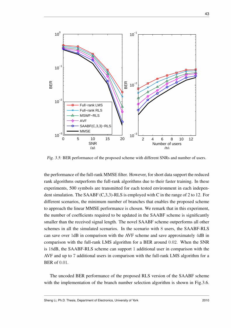
43
0 5 10 15 2010
−3
10−2
10−1
100
SNR(a)
BE
R
2 4 6 8 10 1210
−3
10−2
10−1
Number of users(b)
BE
R
Full−rank LMS
Full−rank RLS
MSWF−RLS
AVF
SAABF(C,3,3)−RLS
MMSE
Fig. 3.5: BER performance of the proposed scheme with different SNRs and number of users.
the performance of the full-rank MMSE filter. However, for short data support the reducedrank algorithms outperform the full-rank algorithms due to their faster training. In theseexperiments, 500 symbols are transmitted for each tested environment in each indepen-dent simulation. The SAABF (C,3,3)-RLS is employed with C in the range of 2 to 12. Fordifferent scenarios, the minimum number of branches that enables the proposed schemeto approach the linear MMSE performance is chosen. We remark that in this experiment,the number of coefficients required to be updated in the SAABF scheme is significantlysmaller than the received signal length. The novel SAABF scheme outperforms all otherschemes in all the simulated scenarios. In the scenario with 8 users, the SAABF-RLScan save over 1dB in comparison with the AVF scheme and save approximately 4dB incomparison with the full-rank LMS algorithm for a BER around 0.02. When the SNRis 18dB, the SAABF-RLS scheme can support 1 additional user in comparison with theAVF and up to 7 additional users in comparison with the full-rank LMS algorithm for aBER of 0.01.
The uncoded BER performance of the proposed RLS version of the SAABF schemewith the implementation of the branch number selection algorithm is shown in Fig.3.6.
Sheng Li, Ph.D. Thesis, Department of Electronics, University of York 2010

44
0 100 200 300 400 50010
−3
10−2
10−1
100
Number of symbols
BE
R
SAABF(6,3,3)−RLSSAABF(12,3,3)−RLSSAABF(Cr,3,3)−RLS, γ=1, ave=9.3SAABF(Cr,3,3)−RLS, γ=3, ave=8.1SAABF(Cr,3,3)−RLS, γ=5, ave=6.9MMSE
Fig. 3.6: BER performance of the SAABF scheme with branch-number selection. The scenarioof 20dB and 8 users are considered. The parameters used: SAABF-RLS (λ = 0.998,δ = 10). For branch-number selection algorithm: Cmin = 6 and Cmax = 12, threshold γis in the unit of dB.
The proposed algorithm instantaneously chooses the number of branches Cr using (3.33),from the range Cmin = 6 to Cmax = 12. As the threshold γ increasing, the averagerequired number of branches Cr and the overall complexity are reducing, but the perfor-mance degrading. For a 1dB threshold, the performance of the branch number selectionSAABF (Cr,D,q) is very close to the SAABF (Cmax,D,q), while the average branch num-ber Cr is only 9.3, which is considerably lower than the Cmax = 12. Hence, with thebranch number selection algorithm we obtain a solution which has lower complexity andsimilar performance to that when the Cmax is used.
Fig.3.7 compares the BER performance of the SAABF-LMS using the rank-adaptationalgorithm with C = 5 and q = 3. The results using a fixed-rank of 3 and 8 are alsoshown in Fig.3.7 for comparison purposes and illustration of the sensitivity of the SAABFscheme to the rank D. The rank-adaptation solution selects the optimal rank Do(i) using(4.61) for each time instant, from the range Dmin = 3 to Dmax = 8. The BER performanceof the SAABF scheme with the rank-adaptation algorithm outperforms the fixed-rank
Sheng Li, Ph.D. Thesis, Department of Electronics, University of York 2010

45
0 100 200 300 400 50010
−2
10−1
100
Number of symbols
BE
R
SAABF(5,3,3)−LMSSAABF(5,8,3)−LMSSAABF(5,D
o,3)−LMS
MMSE
Fig. 3.7: BER performance of the SAABF scheme with rank adaptation. The scenario of 16dB and8 users are considered. The parameters used: SAABF-LMS (µw = 0.15, µψ = 0.15).For rank-adaptation algorithm: Dmin = 3, Dmax = 8 and λD = 0.998.
SAABF scheme with Dmin or Dmax. In this environment, D = 8 has better steady-stateperformance than D = 3, with both cases showing the same convergence speed.Therank-adaptation algorithm provides a better tradeoff between the convergence speed andthe steady-state performance.
Fig.3.8 shows the BER behavior of the SAABF-RLS scheme with the adaptive algo-rithm determining q, which is the length of the inner function. The value of qo(i) for eachtime instant is determined by (3.41), we set qmin = 3 and qmax = 8 and the forgettingfactor is set to λq = 0.998. A clear improvement is shown when the algorithm that selectsq is used. It also can be seen that, in the cases with fixed q, smaller values of q could leadto faster convergence, however it introduces losses to the steady-state performance.
In the last experiment, we conduct a comparison of the proposed and existing linearreceiver structures as shown in Fig. 3.9. In a system with 8 users, we examine the per-formance of the traditional RAKE receiver with the maximal-ratio combining (MRC), thereduced-order multiuser detection (RMUD) [36] with 15 taps, the generic algorithm (GA)
Sheng Li, Ph.D. Thesis, Department of Electronics, University of York 2010

46
0 100 200 300 400 50010
−2
10−1
100
Number of symbols
BE
R
SAABF(5,3,3)−RLSSAABF(5,3,8)−RLSSAABF(5,3,q
o)−RLS
MMSE
Fig. 3.8: BER performance of the SAABF scheme with adaptive short function length. Thescenario of 16dB and 8 users are considered. The parameters used: SAABF-RLS(λ = 0.998, δ = 10). qmin = 3, qmax = 8 and λq = 0.998.
based RAKE-MMSE receiver [32] with 25 fingers and 20 iterations and the proposedSAABF-RLS scheme (the parameters are the same as in Fig.3.5). For each independentrun, 500 symbols are transmitted. The receiver with the SAABF-RLS scheme outper-forms other receiver structures especially in high SNR scenarios. Compared with theGA-RAKE-MMSE scheme, a 2dB gain is obtained for a BER around 10−2. The proposedSAABF scheme is able to suppress the interference efficiently without the knowledge ofthe channel, the noise variance and the spreading codes.
3.8 Conclusions
In this chapter, we have introduced a generic reduced-rank scheme for interferencesuppression, which jointly updates the projection vector and the reduced-rank filter. Then,by constraining the design of the projection vector in the generic scheme, we investigateda novel reduced-rank interference suppression scheme based on switched approximationsof adaptive basis function (SAABF) for DS-UWB system. LMS and RLS algorithms weredeveloped for adaptive estimation of the parameters of the SAABF scheme. The uncoded
Sheng Li, Ph.D. Thesis, Department of Electronics, University of York 2010

47
0 5 10 15 2010
−3
10−2
10−1
100
SNR
BE
R
RAKE−MRCR−MUDGA−RAKE−MMSESAABF(C,3,3)−RLSMMSE
Fig. 3.9: BER performance against SNR of different receiver structures in a system with 8 users.
BER performance of the novel receiver structure was then evaluated in various scenar-ios with severe MAI and ISI. With a low complexity, the SAABF scheme outperformsother reduced-rank schemes and full-rank schemes. A discussion of the global optimal-ity of the reduced-rank filter was presented, and the relationships between the SAABFand the generic scheme and the full-rank scheme were established and are shown in theAppendices A and B.
Sheng Li, Ph.D. Thesis, Department of Electronics, University of York 2010

4. BLIND REDUCED-RANK ADAPTIVE RECEIVERS FORDS-UWB SYSTEMS BASED ON THE JIO AND CCM CRITERION
Contents4.1 Introduction . . . . . . . . . . . . . . . . . . . . . . . . . . . . . . . 48
4.2 Proposed Blind JIO Reduced-Rank Receiver Design . . . . . . . . . 50
4.3 Proposed JIO-NSG Algorithms . . . . . . . . . . . . . . . . . . . . . 54
4.4 Proposed JIO-RLS Algorithms . . . . . . . . . . . . . . . . . . . . . 58
4.5 Complexity Analysis and Rank Adaptation Algorithm . . . . . . . . 64
4.6 Simulations . . . . . . . . . . . . . . . . . . . . . . . . . . . . . . . . 68
4.7 Conclusion . . . . . . . . . . . . . . . . . . . . . . . . . . . . . . . . 71
4.1 Introduction
Blind adaptive linear receivers have high spectrum efficiency and low complexity de-signs can be obtained by solving constrained optimization problems based on the CCMor CMV criterion [56], [59]. The CCM criterion-based receivers have shown better per-formance and increased robustness against signature mismatch over the CMV based ap-proaches [56], [58]. Recently, CCM based blind full-rank SG and RLS adaptive filtershave been proposed for multiuser detection in DS-UWB communications [59], [60]. Inorder to achieve faster convergence and increase the robustness against the interference,reduced-rank filtering techniques can be implemented. In [61], a blind subspace mul-tiuser detection scheme is proposed for UWB systems which requires the expensive eigen-decomposition of the covariance matrix of the received signal.
In this chapter, a low-complexity CCM based joint iterative optimization (JIO) blindreduced-rank receiver is proposed. A projection matrix and a reduced-rank filter constructthe proposed receiver and they are updated jointly and iteratively to minimize the CMcost function subject to a constraint. The constraint is adopted to avoid the undesiredlocal minima. Adaptive NSG and RLS algorithms are developed for the JIO receiver.

49
In the NSG version, a low-complexity leakage SG channel estimator that was proposedin [64] is adopted. Applying an approximation of the covariance matrix of the receivedsignal, the RLS channel estimator proposed in [64] is modified for the proposed JIO-RLSwith reduced complexity. Since each column of the projection matrix can be consideredas a direction vector on one dimension of the subspace, we update the projection matrixcolumn by column to achieve a better representation of the projection procedure in theJIO-RLS. The main contributions of this chapter are summarized as follows:
• A novel linear blind JIO reduced-rank receiver based on the CCM criterion is pro-posed for interference suppression in DS-UWB systems.
• NSG algorithms, which are able to facilitate the setting of step sizes in multiuserscenarios, are developed for the proposed reduced-rank receivers.
• RLS algorithms are developed to jointly update the columns of the projection matrixand the reduced-rank filter with low complexity.
• A rank adaptation algorithm is developed to achieve a better tradeoff between theconvergence speed and the steady state performance.
• The convergence properties of the CM cost function with a constraint are discussed.
• Simulations are performed with the IEEE 802.15.4a channel model and severe ISIand MAI are assumed for the evaluation of the proposed scheme against existingtechniques.
The rest of this chapter is structured as follows. The design of the JIO CCM blindreceiver is detailed in Section 4.2. The proposed NSG and RLS versions of the blind JIOreceiver are described in Section 4.3 and 4.4, respectively. In Section 4.5, a complexityanalysis for the proposed receiver versions is detailed and a rank adaptation algorithm isdeveloped for the JIO receiver. Simulation results are shown in Section 4.6 and conclu-sions are drawn in Section 4.7.
Sheng Li, Ph.D. Thesis, Department of Electronics, University of York 2010

50
( )ir ( )ir
( )ih Proposed JIO Algorithm
( )y iProjection
Matrix ( )iT
Reduced-rank
Filter ( )iw1M ´ 1D´
^
Fig. 4.1: Block diagram of the proposed blind reduced-rank receiver.
4.2 Proposed Blind JIO Reduced-Rank Receiver Design
In this section, we firstly detail the design of the proposed JIO reduced-rank receiverthat is able to recover the data symbol from the noisy received signal as shown in (2.5)with only the knowledge of the spreading code of the desired user and the timing. Then,a blind channel estimation algorithm is detailed.
4.2.1 Blind JIO Reduced-Rank Receiver
The block diagram of the proposed receiver is shown in Fig.4.1. In the JIO blind linearreceiver, the reduced-rank received signal can be expressed as
r(i) = TH(i)r(i), (4.1)
where T(i) is the M -by-D (where D ¿ M ) projection matrix. After the projection, r(i)is fed into the reduced-rank filter w(i) and the output signal is given by
y(i) = wH(i)r(i). (4.2)
The decision of the desired data symbol is defined as
b(i) = sign(R[y(i)]). (4.3)
where sign(·) is the algebraic sign function and R(·) represents the real part of a complexnumber.
Sheng Li, Ph.D. Thesis, Department of Electronics, University of York 2010

51
The optimization problem to be solved can be expressed as
[w(i),T(i)] = arg minw(i),T(i)
JJIO
(w(i),T(i)
), (4.4)
subject to the constraintwH(i)TH(i)p = �, (4.5)
where p = PrSeh is defined as the effective signature vector for the desired user and � isa real-valued constant to ensure the convexity of the CM cost function
JJIO
(w(i),T(i)
)=
1
2E
[(|y(i)|2 − 1)2
]. (4.6)
The convergence properties of the CM cost function subject to a constraint are discussedin Appendix C.
Let us now consider the problem through the Lagrangian
LJIO
(w(i),T(i)
)=
1
2E
[(|y(i)|2 − 1)2
]+ R[λ(i)(wH(i)TH(i)p− �)], (4.7)
where λ(i) is a complex-valued Lagrange multiplier. In order to obtain the adaptationequation of T(i), we firstly assume that w(i) is fixed and the gradient of the Lagrangianwith respect to T(i) is given by
∇TLJIO = E[e(i)y∗(i)r(i)wH(i)
]+
λT (i)
2pwH(i), (4.8)
where λT (i) is the complex-valued Lagrange multiplier for updating the projection matrixand e(i) = |y(i)|2 − 1 is defined as a real-valued error signal. Recalling the relationshipy∗(i) = rH(i)T(i)w(i) and setting (4.8) to a zero matrix, we obtain
Topt = R−1Y
(DT − λT (i)
2pwH(i)
)R−1
w , (4.9)
where RY = E[|y(i)|2r(i)rH(i)], DT = E[y∗(i)r(i)wH(i)] and Rw = E[w(i)wH(i)].Using the constraint wH(i)TH
optp = �, we obtain the Lagrange multiplier
λT (i) = 2
(wH(i)R−1
w DTR−1Y p− �
wH(i)R−1w w(i)pHR−1
Y p
)∗. (4.10)
Finally, the expression for Topt is given by
Topt = R−1Y
(DT −
(wH(i)R−1
w DTR−1Y p− �
wH(i)R−1w w(i)pHR−1
Y p
)∗pwH(i)
)R−1
w . (4.11)
Sheng Li, Ph.D. Thesis, Department of Electronics, University of York 2010

52
Now, we assume that T(i) is fixed in (4.7) and calculate the gradient of the Lagrangianwith respect to w(i) which is given by
∇wLJIO = E[e(i)TH(i)r(i)y∗(i)
]+
λw(i)
2TH(i)p, (4.12)
where λw(i) is the complex-valued Lagrange multiplier for updating the reduced-rankfilter. Rearranging the terms, we obtain
wopt = R−1y
(dr − λw(i)
2TH(i)p
), (4.13)
where Ry = E[|y(i)|2r(i)rH(i)] and dr = E[y∗(i)r(i)]. Using the constraintwH
optTH(i)p = �, we obtain the Lagrange multiplier
λw(i) = 2
(dH
r R−1y TH(i)p− �
pHT(i)R−1y TH(i)p
)∗. (4.14)
Finally, the expression for wopt is given by
wopt = R−1y
(dr −
(dH
r R−1y TH(i)p− �
pHT(i)R−1y TH(i)p
)∗TH(i)p
). (4.15)
With the solutions of Topt and wopt, the NSG and RLS adaptive versions of the JIOreceiver will be developed in the following sections, in which the direct matrix inversionsare not required and the computational complexity is reduced. Note that when adaptivealgorithms are implemented to estimate Topt and wopt, T(i) is a function of w(i) andw(i) is a function of T(i). Thus, the optimal CCM design is not in a closed form and onepossible solution for such optimization problem is to jointly and iteratively adapt thesetwo quantities. The joint update means for the i-th time instant, T(i) is updated with theknowledge of T(i− 1) and w(i− 1), then w(i) is updated with T(i) and w(i− 1). Eachiterative update can be considered as one repetition of the joint update.
4.2.2 Blind Channel Estimation
It should also be noted that the blind JIO receiver design requires the knowledge of theeffective signature vector of the desired user, or equivalently, the channel parameters. Inthis work, the channel coefficients are not given and must be estimated.
In order to facilitate the development of the blind channel estimation, we rearrange the
Sheng Li, Ph.D. Thesis, Department of Electronics, University of York 2010

53
term and express the received signal as
r(i) =K∑
k=1
√EkPrSe,khkbk(i) + η(i) + n(i) =
K∑
k=1
xk(i) + η(i) + n(i), (4.16)
where Se,k is the Toeplitz matrix with the first column being the vector se,k = Ptsk zero-padded to length MH . The matrix Pr represents the MF and chip-rate sampling with thesize M -by-MH . Pt denotes the (Ts/Tτ )-by-Nc pulse shaping matrix.
Let us perform singular value decomposition (SVD) on the covariance matrix R asin [62]:
R = E[r(i)rH(i)] = [Vs Vn]
[Λs + σ2I 0
0 σ2I
][Vs Vn]H (4.17)
where Vs and Vn are the signal (includes the ISI) and the noise subspaces, respectively.Because of the orthogonality of the signal subspace and the noise subspace [63], [64], wehave VH
n xk(i) = VHn PrSe,khk = 0 and hence we have
Υ = hHk SH
e,kPHr VnV
Hn PrSe,khk = 0. (4.18)
Assuming that Vn is given, it suffices to consider only Υ, which allows the recov-ery of hk as the eigenvector corresponding to the smallest eigenvalue of the matrixSH
e,kPHr VnV
Hn PrSe,k. A traditional approach to obtain the noise subspace Vn and its
rank is to do the SVD on the covariance matrix R, which is computational expensive. Toavoid the SVD on R, the following lemma is adopted [62]:
Lemma: Consider the SVD on R as in (4.17), then we have:
limp→∞
(R/σ2)−m = VnVHn . (4.19)
Hence, the channel coefficients for the desired user can be obtained by the optimization:
h(i) = arg minh(i)
hH(i)SHe PH
r R−mPrSeh(i), (4.20)
subject to ‖h(i)‖ = 1, where m is an integer and R(i) is the estimated covariance matrix.The solution of the h(i) is the eigenvector corresponding to the minimum eigenvalue ofthe matrix SH
e PHr R−mPrSe that can be obtained using SVD. Note that the scalar quantity
(σ2)m is discarded in this optimization problem because it does not affect the subspacedetermination problem [64]. The performance of the estimator can be improved by in-creasing m even though our studies reveal that it suffices to use powers up to m = 3. Inorder to achieve further complexity reduction, we employ the variant of the power method
Sheng Li, Ph.D. Thesis, Department of Electronics, University of York 2010

54
introduced in [64] to avoid the SVD of the matrix SHe PH
r R−mPrSe. Hence, we have
h(i) =(I− V(i)/tr[V(i)]
)h(i− 1), (4.21)
where the L-by-L matrix is defined as
V(i) = SHe PH
r R−m(i)PrSe, (4.22)
and I is the identity matrix, tr[·] stands for trace and we make h(i) ← h(i)/‖h(i)‖to normalize the channel. R(i) =
∑ij=1 αi−jr(j)rH(j) and m is a finite power. The
estimate of the matrix R−1(i) is obtained recursively via the matrix inversion lemma [26]and is given by
R−1(i) =1
α
(R−1(i− 1)− (φ(i)κ(i))κH(i)
), (4.23)
where α is the forgetting factor, κ(i) = R−1(i − 1)r(i) and φ(i) =(α + rH(i)κ(i)
)−1.The estimator of the inversion of the covariance matrix requires 3M2 + 2M + 1 mul-tiplications and 2M2 additions. Equation (4.22) requires (m + 1)M2L multiplicationsand (m + 1)M2L − (m + 1)ML additions, while equation (4.21) requires L2 multipli-cations and L2 + L− 1 additions (the multiplications and additions in this work are bothcomplex-valued operations). Note that, the matrix PrSe is assumed given at the receiver.
The estimate of the effective signature vector can be finally obtained as
p(i) = PrSeh(i), (4.24)
where h(i) is given in (4.21).
4.3 Proposed JIO-NSG Algorithms
In this section, we develop the NSG algorithm to jointly and iteratively update T(i)
and w(i). The blind channel estimator based on the leakage SG algorithm that is proposedin [64] is implemented to provide the channel coefficients.
Sheng Li, Ph.D. Thesis, Department of Electronics, University of York 2010

55
4.3.1 JIO-NSG Algorithms
The optimization problem to be solved in the NSG version is given by
[w(i),T(i)] = arg minw(i),T(i)
JJIO
(w(i),T(i)
), (4.25)
subject to wH(i)TH(i)p(i) = �, where p(i) is the estimated signature vector obtainedvia blind channel estimation that will be detailed in Section 4.3.2 and � is a real-valuedconstant to ensure the convexity of the cost function
JJIO−NSG
(w(i),T(i)
)=
1
2E
[(|y(i)|2 − 1)2
]. (4.26)
Here, we consider the problem through the Lagrangian
LJIO−NSG
(w(i),T(i)
)=
1
2E
[(|y(i)|2 − 1)2
]+R[λN(i)(wH(i)TH(i)p(i)−�)], (4.27)
where λN(i) is a complex-valued Lagrange multiplier. For each time instant, we firstlyupdate T(i) while assuming that w(i) is fixed. Then we adapt w(i) with the updatedT(i).
The gradient of the Lagrangian with respect to T(i) is given by
∇TLJIO−NSG = E[e(i)y∗(i)r(i)wH(i)
]+
1
2λNT (i)p(i)wH(i),
where λNT (i) is the complex-valued Lagrange multiplier for updating the projection ma-trix and e(i) = |y(i)|2−1 is defined as a real-valued error signal. Using the instantaneousestimator to the gradient vector, the SG update equation is given by
T(i + 1) = T(i)− µT
(e(i)y∗(i)r(i) +
λNT (i)
2p(i)
)wH(i), (4.28)
where µT is the step size for the SG algorithm that updates the projection matrix. Usingthe constraint of wH(i)TH(i + 1)p(i) = �, we obtain that
λNT (i) = 2pH(i)T(i)w(i)− µT e(i)y∗(i)‖w(i)‖2pH(i)r(i)− �
µT‖w(i)‖2‖p(i)‖2. (4.29)
The NSG algorithm aims at minimizing the cost function
JJIO−NSG(µT ) =1
2
[∣∣wH(i)TH(i + 1)r(i)∣∣2 − 1
]2
. (4.30)
Substituting (4.28) and (4.29) into (4.30) and setting the gradient vector of (4.30) with
Sheng Li, Ph.D. Thesis, Department of Electronics, University of York 2010

56
respect to µT to zeros, we obtain the solutions
µT,1 =|y(i)| − 1
|y(i)|e(i)AT,1
, µT,2 =|y(i)|+ 1
|y(i)|e(i)AT,1
,
µT,3 = µT,4 =1
e(i)AT,1
,
where the real-valued scale term AT,1 is defined as
AT,1 = ‖w(i)‖2
[‖r(i)‖2 − |rH(i)p(i)|2
‖p(i)‖2
].
By examining the second derivative of (4.30) with respect to µT , we conclude that µT,1
and µT,2 are the solutions that correspond to the minima. In this work, the µT,1 is usedand a positive real scaling factor µT,0 is implemented that will not change the direction ofthe tap-weight vector. Finally, the NSG update function of T(i) is given by
T(i + 1) = T(i)− y∗(i)µT,0AT,2 − AT,3p(i)wH(i). (4.31)
where
AT,2 =|y(i)| − 1
|y(i)|AT,1
(r(i)wH(i)− pH(i)r(i)
‖p(i)‖2p(i)wH(i)
),
AT,3 =(‖w(i)‖2‖p(i)‖2
)−1(pH(i)T(i)w(i)− �
).
Now, let us adapt w(i) while assuming T(i) is fixed. The gradient of the Lagrangian withrespect to w(i) is given by∇wLJIO−NSG = E
[e(i)y∗(i)TH(i)r(i)
]+ 1
2λNw(i)p(i)wH(i),
where λNw(i) is the complex-valued Lagrange multiplier for updating the reduced-rankfilter. By using the instantaneous estimator of the gradient vector, the SG adaptationequation is given by
w(i + 1) = w(i)− µwe(i)y∗(i)TH(i)r(i)− µwλNw(i)
2TH(i)p(i). (4.32)
Using the constraint wH(i + 1)TH(i)p(i) = �, we have
λNw(i) = 2pH(i)T(i)w(i)− µwe(i)y∗(i)pH(i)T(i)TH(i)r(i)− �
µw‖TH(i)p(i)‖2. (4.33)
The NSG algorithm for updating the reduced-rank filter aims at minimizing the cost func-tion
JJIO−NSG(µw) =1
2
[∣∣wH(i + 1)TH(i)r(i)∣∣2 − 1
]2
. (4.34)
Substituting (4.32) and (4.33) into (4.34), the solutions of µw that correspond to a null
Sheng Li, Ph.D. Thesis, Department of Electronics, University of York 2010
57
gradient vector of (4.34) are given by
µw,1 =|y(i)| − 1
|y(i)|e(i)Aw,1
, µw,2 =|y(i)|+ 1
|y(i)|e(i)Aw,1
,
µw,3 = µw,4 =1
e(i)Aw,1
,
where the scale term is given by
Aw,1 = ‖TH(i)r(i)‖2 − |rH(i)T(i)TH(i)p(i)|2‖TH(i)p(i)‖2
By examining the second derivative of (4.34) with respect to µw, only µw,1 and µw,2
correspond to the minima of the cost function (4.34). Finally, by applying a positive realscaling factor µw,0 to control the tap-weight vector, the adaptation equation by using µw,1
is given bywH(i + 1) = wH(i)− y∗(i)µw,0Aw,2 − Aw,3T
H(i)p(i). (4.35)
where
Aw,2 =|y(i)| − 1
|y(i)|Aw,1
(TH(i)r(i)− pH(i)T(i)TH(i)r(i)
‖TH(i)p(i)‖2TH(i)p(i)
),
Aw,3 =(‖TH(i)p(i)‖2
)−1(pH(i)T(i)w(i)− �
).
In the proposed JIO-NSG scheme, T(i) and w(i) are computed jointly and iteratively.Let c denote the iteration number and define cmax as the total number of iterations foreach time instant. We have T0(i) = Tcmax(i− 1) and w0(i) = wcmax(i− 1). For the c-thiteration, Tc(i) is updated with Tc−1(i) and wc−1(i) using (4.31), then wc(i) is trainedwith Tc(i) and wc−1(i) via (4.35).
It is interesting to note that the complexity of the JIO-NSG scheme could be lower thanthe full-rank NSG algorithm because there are many entries that are frequently reused inthe update equations, for example, the scalar term pH(i)r(i), the vectors of TH(i)p(i) andTH(i)r(i). However, the price we pay for the complexity reduction is the requirement ofextra storage space at the receiver.
Sheng Li, Ph.D. Thesis, Department of Electronics, University of York 2010

58
4.3.2 Blind Channel Estimator for the NSG Version
For the JIO-NSG receiver, we rearrange the equation (4.22) as
V(i) = SHe PH
r W(i) (4.36)
where W(i) = R−m(i)PrSe. Here, we implement the Leakage SG algorithm to estimateW(i), which can be expressed as [64]
Wl(i) = λvWl(i− 1) + µv(Wl−1(i)− r(i)rH(i)Wl(i− 1)), (4.37)
where l = 1, . . . , m is defined as the iteration index, λv is the leakage factor and µv is thestep size. Using (4.36), we obtain the leakage SG blind channel estimator that is given by
h(i) = h(i− 1)−(V(i)h(i− 1)
)/tr[V(i)], (4.38)
Finally, the effective signature vector of the desired user is given by
p(i) = PrSeh(i) (4.39)
In terms of the computational complexity, we need 4mML multiplications and 3mML−mL additions for all the recursions in (4.37); L2M multiplications and L2M − L2 addi-tions for (4.36).
The JIO-NSG version is summarized in Table. 4.1.
4.4 Proposed JIO-RLS Algorithms
In this section we detail the RLS version of the proposed JIO scheme. In the JIOscheme, the M -by-D (where D ¿ M ) projection matrix can be expressed as
T(i) = [t1(i), t2(i), . . . , tD(i)]. (4.40)
Note that the reduced-rank received signal can be expressed as r(i) = TH(i)r(i), whosed-th element is rd(i) = tH
d (i)r(i). Since the projection matrix projects the received signalonto a small-dimensional subspace, these vectors td(i) can be considered as the directionvectors on each dimension of the subspace. For each time instant, we compute these M -dimensional vectors td(i) (where d = 1, 2, . . . , D) one by one. One of the advantagesof this method in the RLS version is that the complexity of training the projection ma-
Sheng Li, Ph.D. Thesis, Department of Electronics, University of York 2010

59
Tab. 4.1: NSG version of the Proposed JIO-CCM Receiver.
NSG version:
Initialization:w(1) = [1, 1, 1, . . . , 1], D-by-1 vector ; T(1) = [ID | 0]T , M -by-D matrix.
for i = 1, 2, . . .1: Pre-adaptation:r(i) = TH(i)r(i), y(i) = wH(i)r(i),Calculate V(i) and h(i) using (4.36) and (4.38), respectively,Calculate p(i) using (4.39),Set T0(i + 1) = Tcmax(i) and w0(i + 1) = wcmax(i).
2: Adaptation of T(i + 1) and w(i + 1):for c = 1, 2, . . . , cmax
Update Tc(i + 1) using (4.31) with Tc−1(i + 1) and wc−1(i + 1),Update wc(i + 1) using (4.35) with Tc(i + 1) and wc−1(i + 1),endSet T(i + 1) = Tcmax(i + 1) and w(i + 1) = wcmax(i + 1)
3: Make Decision for the i-th data bit:b(i) = sign(R(y(i)))
trix could be reduced with an approximation which will be shown soon. In addition, thismethod provides a better representation of the projection matrix and leads to better perfor-mance than the approach that updates all the columns of the projection matrix together. Itshould be noted that, the NSG version can also be modified to update the columns of theprojection matrix one by one, but the limited improved performance in the NSG versionis not worth the payment of the increased complexity.
After the projection, r(i) is fed into the reduced-rank filter w(i) and the output signalis given by
y(i) = wH(i)TH(i)r(i) = wH(i)D∑
d=1
tHd (i)r(i)qd,
where qd (where d = 1, 2, . . . , D) are the vectors whose d-th elements are ones, whileall the other elements are zeros. In this section, an adaptive blind channel estimation isemployed and td(i) are optimized jointly and iteratively with w(i) via RLS algorithms.
Sheng Li, Ph.D. Thesis, Department of Electronics, University of York 2010

60
4.4.1 JIO-RLS Algorithms
In the JIO-RLS scheme, we need to solve the optimization problem
[w(i), t1(i), . . . , tD(i)] = arg minw(i),t1(i),...,tD(i)
JJIO−RLS
(w(i), t1(i), . . . , tD(i)
), (4.41)
subject to the constraint wH(i)∑D
d=1 tHd (i)p(i)qd = �, where p(i) is the estimated sig-
nature vector obtained via blind channel estimation that will be detailed in Section 4.4.2,and � is a real-valued constant to ensure the convexity of the CM cost function given by
JJIO−RLS
(w(i), t1(i), . . . , tD(i)
)=
1
2
i∑j=1
αi−j(|y(j)|2 − 1
)2,
where 0 < α ≤ 1 is the forgetting factor and y(i) is the output signal at the i-th timeinstant. Let us now consider the problem through the Lagrangian
LJIO−RLS
(w(i), t1(i), . . . , tD(i)
)=
1
2
i∑j=1
αi−j(|y(j)|2 − 1
)2
+ R
[λR(i)
(wH(i)
D∑
d=1
tHd (i)p(i)qd − �
)]
,
(4.42)
where λR(i) is a complex-valued Lagrange multiplier. In the proposed JIO-RLS scheme,for each time instant, we firstly update the vectors td(i) (where d = 1, 2, . . . , D) whileassuming that w(i) and other column vectors are fixed. Then we adapt the reduced-rankfilter with the updated projection matrix.
For the update of the column vectors of the projection matrix, we can divide the outputsignal as follows
y(i) = wH(i)D∑
d=1
tHd (i)r(i)qd = w∗
d(i)rd(i) + wH(i)re(i),
where the D-dimensional vector re(i) can be obtained by calculating the reduced-rankreceived signal r(i) and setting its d-th element to zero. By computing the gradient termof (4.42) with respect to td(i) and setting it to a null vector, we have
∇tdLJIO−RLS
=i∑
j=1
αi−je(j)r(j)(|wd(j)|2rH(j)td(i) + w∗
d(j)rHe (j)w(j)
)+
1
2λt,d(i)w
∗d(i)p(i) = 0,
Sheng Li, Ph.D. Thesis, Department of Electronics, University of York 2010

61
where e(i) = |y(i)|2− 1 and λt,d(i) is the complex-valued Lagrange multiplier for updat-ing the d-th column vector in the projection matrix. Rearranging the terms we obtain
td(i) = −R−1d (i)
(λt,d(i)
2w∗
d(i)p(i) + vr(i)
), (4.43)
where we define the M -dimensional vector
vr(i) =i∑
j=1
αi−jw∗d(j)r(j)
(e(j)rH
e (j)w(j)− wd(j)r∗d(j)
)(4.44)
and the M -by-M matrix
Rd(i) =i∑
j=1
αi−j|wd(j)|2|y(j)|2r(j)rH(j). (4.45)
Note that, Rd(i) is dependent on wd(i), which is the d-th element of the reduced-rankfilter. Hence, for updating each td(i), we need to calculate the corresponding R−1
d (i) andthat leads to high computational complexity. Assuming that wd(i) ≈ wd(i+1), we devisean approximation
Rd(i) ≈ |wd(i)|2i∑
j=1
αi−j|y(j)|2r(j)rH(j) = |wd(i)|2Ry(i). (4.46)
Then we adopt the matrix inversion lemma [26] to recursively estimate R−1y (i) as follows
κy(i) = R−1y (i− 1)y(i)r(i),
φy(i) =1
α + y∗(i)rH(i)κy(i),
R−1y (i) =
1
α
(R−1
y (i− 1)− (φ(i)κy(i))κHy (i)
),
(4.47)
where R−1y (i) is the estimate of R−1
y (i). We use R−1y (i) for all the adaptations of td(i) to
avoid the estimation of the R−1d (i) (where d = 1, 2, . . . , D) and the new update equation
is given by
td(i) = − R−1y (i)
|wd(i)|2(
λt,d(i)
2w∗
d(i)p(i) + vr(i)
). (4.48)
Using the constraint wH(i)∑D
d=1 tHd (i)p(i)qd = �, we obtain the expression of the La-
grange multiplier as
λt,d(i) = 2
[w∗
d(i)vHr (i)R−1
y (i)p(i) +(�− wH(i)pd(i)
)|wd(i)|2−|wd(i)|2pH(i)R−1
y (i)p(i)
]∗, (4.49)
Sheng Li, Ph.D. Thesis, Department of Electronics, University of York 2010

62
where pd(i) can be obtained by calculating the vector TH(i)p(i) and setting its d-th ele-ment to zero. Note that in the update equation (4.48), small values of |wd(i)|2 may causenumerical problems for the later calculation. This issue can be addressed by normalizingthe column vector after each adaptation, which is given by td(i) ← td(i)/‖td(i)‖.
After updating the projection matrix column by column, now we are going to adapt thereduced-rank filter w(i). By assuming that the projection matrix is fixed, we can expressthe output signal in a simpler way as
y(i) = wH(i)TH(i)r(i), (4.50)
where T(i) = [t1(i), . . . , tD(i)] and the constraint can be expressed aswH(i)TH(i)p(i) = �. Hence, the Lagrangian becomes
LJIO−RLS
(w(i),T(i)
)=
1
2
i∑j=1
αi−j(|y(j)|2 − 1
)2+ R[λR(i)
(wH(i)TH(i)p(i)− �
)].
(4.51)By taking the gradient term of (4.51) with respect to w(i) and setting it to a null vector,we have
∇wLJIO−RLS =i∑
j=1
αi−je(j)TH(j)r(j)rH(j)T(j)w(i) +1
2λRw(i)TH(i)p(i) = 0,
where the real-valued error is e(i) = (|y(i)|2 − 1) and λRw(i) is the complex-valuedLagrange multiplier for updating the reduced-rank filter, rearranging the terms we obtain
w(i) = R−1T (i)
(−λRw(i)
2TH(i)p(i) + d(i)
), (4.52)
where RT(i) =∑i
j=1 αi−j|y(j)|2r(j)rH(j) and d(i) =∑i
j=1 αi−j r(j)y∗(j) = d(i −1) + αr(i)y∗(i). The matrix inversion lemma [26] is used again to recursively estimatethe inversion matrix R−1
T (i) as follows
κT(i) = R−1T (i− 1)r(i)y(i),
φT(i) =1
α + y(i)∗rH(i)κT(i),
R−1T (i) =
1
α
(R−1
T (i− 1)− (φT(i)κT(i))κHT (i)
),
(4.53)
where R−1T (i) is the estimate of R−1
T (i). For calculating the Lagrange multiplier, we use
Sheng Li, Ph.D. Thesis, Department of Electronics, University of York 2010

63
Tab. 4.2: RLS version of the Proposed JIO-CCM Receiver.
RLS version:
Initialization:w(1) = [1, 1, 1, . . . , 1], D-by-1 vector ; R−1
T (0) = ID/δ, D-by-D matrix;td(1) = [1, 0, 0, . . . , 0] (d = 1, 2, . . . , D), D-by-1 vectors;d(0) = [0, 0, . . . , 0], D-by-1 vector ; R−1
y (0) = IM/δ, M -by-M matrix;
for i = 1, 2, . . .1: Pre-adaptation:r(i) = TH(i)r(i), y(i) = wH(i)r(i), d(i) = d(i− 1) + αr(i)y∗(i),Estimate R−1
y (i) and R−1T (i) using (4.47) and (4.53), respectively,
Calculate V(i) and h(i) using (4.56) and (4.55), respectively,Calculate p(i) using (4.57).
2: Adaptation of td(i):for d = 1, 2, · · · , DCalculate λt,d(i) using (4.49), Update td(i) using (4.48),Normalize td(i) ← td(i)/ ‖ td(i) ‖.
3: Adaptation of w(i):Calculate λRw(i) using (4.54), Update w(i) using (4.52),
4: Make Decision for the i-th data bit:b(i) = sign(R(y(i)))
the constraint wH(i)TH(i)p(i) = � and obtain
λRw(i) = 2
[dH(i)R−1
T (i)TH(i)p(i)− �pH(i)T(i)R−1
T (i)TH(i)p(i)
]∗. (4.54)
4.4.2 Blind Channel Estimator for the RLS version
In the JIO-RLS algorithm, the estimation of the covariance matrix Ry(i) =∑ij=1 αi−j|y(j)|2r(j)rH(j) and its inversion are obtained in the stage of adapting the
projection matrix. It should be noted that |y(j)|2 tends to 1 as the number of receivedsignal increasing. Hence, by replacing the inverse matrix R−1(i) in (4.22) with R−1
y (i),we obtain
h(i) = h(i− 1)−(V(i)h(i− 1)
)/tr[V(i)], (4.55)
Sheng Li, Ph.D. Thesis, Department of Electronics, University of York 2010
64
where the L-by-L matrix is defined as
V(i) = SHe PH
r R−my (i)PrSe, (4.56)
and the effective signature vector of the desired user is given by
p(i) = PrSeh(i) (4.57)
Using R−1y (i) instead of R−1(i) can save O(M2) in terms of computational complexity
for the JIO-RLS version and simulation results will demonstrate later that the performancewill not be degraded with this replacement. The JIO-RLS version is summarized in Table.4.2.
4.5 Complexity Analysis and Rank Adaptation Algorithm
In this section, a complexity analysis is presented to compare the two versions of theJIO receiver, the full-rank NSG and RLS schemes, the NSG and RLS versions of theMSWF. The computational complexity of the blind channel estimators that are imple-mented in this work are also analyzed. A rank adaptation algorithm is detailed in thissection which is able to select the rank adaptively and can achieve better tradeoffs be-tween the convergence speed and the steady state performances.
4.5.1 Complexity Analysis
As shown in Table. 4.3, the complexity of the analyzed blind CCM full-rank NSG andRLS, MSWF-NSG and MSWF-RLS [56] and the proposed NSG and RLS versions of theJIO scheme is compared with respect to the number of complex additions and complexmultiplications for each time instant. The complexity of the conventional blind channelestimator (BCE) that is described in Section 4.2 is compared with the BCEs for the JIO-NSG and JIO-RLS that are described in Section 4.3.2 and Section 4.4.2, respectively.
For the analysis of the adaptive algorithms, the quantity M is the length of the full-rankfilter, D is the dimension of reduced-rank filter and cmax is the number of iterations forthe JIO-NSG version in each time instant. Note that, only one iteration is required in theJIO-RLS version for each time instant. For the analysis of the BCEs, the quantity L is thelength of the CIR and m is the power of the inverse covariance matrix. In this work, M isthe minimum integer that is larger than the scalar term (Ts/Tτ +TDS/Tτ − 1)/(Tc/Tτ ) =
Sheng Li, Ph.D. Thesis, Department of Electronics, University of York 2010

65
Tab. 4.3: Complexity analysis for the blind algorithms
Complex Additions Complex Multiplications
Full-Rank NSG M2 + 3M − 1 2M2 + 4M + 5
Full-Rank RLS 5M2 + 2M + 1 5M2 + 3M + 1
MSWF-NSG DM2 + (2D + 2)M (D + 1)M2 + (4D + 2)M−2D2 − 2 −2D2 + 4D + 5
MSWF-RLS DM2 + (2D + 2)M (D + 1)M2 + (4D + 2)M+2D2 −D +2D2 + 3D + 1
JIO-NSG cmax(6DM + 3M + 4D − 2) cmax(8DM + 4M + 7D + 11)
JIO-RLS DM2 + 3DM + 4D2 − 4D DM2 + 6DM + 4D2
+15D + 1
Conventional BCE (m + 1)M2L− (m + 1)ML (m + 1)M2L + 3M2 + L2
+2M2 + L2 + L− 1 +2M + 1
BCE for JIO-NSG L2M + 3mML− (m− 1)L− 1 L2M + 4mML + L2
BCE for JIO-RLS (m + 1)M2L− (m + 1)ML (m + 1)M2L + L2
+L2 + L− 1
(Ts + TDS − Tτ )/Tc and L = TDS/Tτ . Since Tτ is set to 0.125ns as for the standardIEEE802.15.4a channel model, symbol duration Ts and chip duration Tc are assumedgiven for the designer. Hence, M and L are both related to the channel delay spreadTDS . In this work, the parameters are set as follows: Ts = 12ns, Tc = 0.375ns, m = 3
and cmax = 3. As shown in Fig. 4.2, the number of complex multiplications requiredfor different algorithms are compared as a function of channel delay spread TDS . TheJIO-RLS algorithm with D = 3 has lower complexity than the MSWF algorithms andthe full-rank RLS. It will be demonstrated by the simulation results that the JIO-RLSalgorithm can achieve fast convergence with a very small rank (D < 5). The proposedJIO-NSG algorithm has lower complexity than the full-rank NSG algorithm in the longchannel delay spread scenarios. As discussed in Section 4.3.1, the price we pay for sucha complexity reduction is the extra storage space at the receiver.
The complexity of the BCEs for the JIO versions is shown in Fig. 4.3, in which thenumber of complex multiplications is shown as a function of channel delay spread TDS .The complexity of the BCE for the JIO-NSG version has lower complexity than the BCEfor the JIO-RLS version in all the analyzed scenarios.
Sheng Li, Ph.D. Thesis, Department of Electronics, University of York 2010
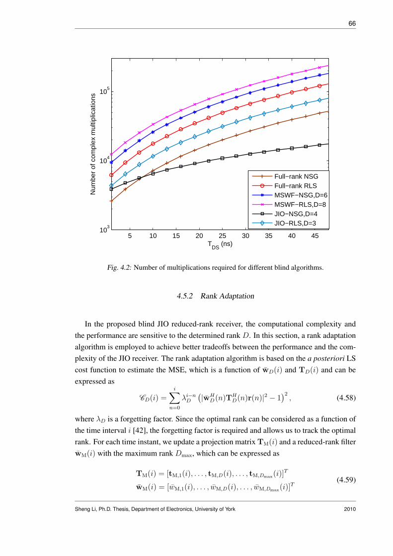
66
5 10 15 20 25 30 35 40 4510
3
104
105
TDS
(ns)
Num
ber
of c
ompl
ex m
ultip
licat
ions
Full−rank NSGFull−rank RLSMSWF−NSG,D=6MSWF−RLS,D=8JIO−NSG,D=4JIO−RLS,D=3
Fig. 4.2: Number of multiplications required for different blind algorithms.
4.5.2 Rank Adaptation
In the proposed blind JIO reduced-rank receiver, the computational complexity andthe performance are sensitive to the determined rank D. In this section, a rank adaptationalgorithm is employed to achieve better tradeoffs between the performance and the com-plexity of the JIO receiver. The rank adaptation algorithm is based on the a posteriori LScost function to estimate the MSE, which is a function of wD(i) and TD(i) and can beexpressed as
CD(i) =i∑
n=0
λi−nD
(|wHD(n)TH
D(n)r(n)|2 − 1)2
, (4.58)
where λD is a forgetting factor. Since the optimal rank can be considered as a function ofthe time interval i [42], the forgetting factor is required and allows us to track the optimalrank. For each time instant, we update a projection matrix TM(i) and a reduced-rank filterwM(i) with the maximum rank Dmax, which can be expressed as
TM(i) = [tM,1(i), . . . , tM,D(i), . . . , tM,Dmax(i)]T
wM(i) = [wM,1(i), . . . , wM,D(i), . . . , wM,Dmax(i)]T
(4.59)
Sheng Li, Ph.D. Thesis, Department of Electronics, University of York 2010

67
5 10 15 20 25 30 35 40 4510
3
104
105
106
107
108
TDS
(ns)
Num
ber
of c
ompl
ex m
ultip
licat
ions
BCE for JIO−NSGBCE for JIO−RLS
Fig. 4.3: Number of multiplications required for BCEs.
After the adaptation, we test values of D within the range Dmin to Dmax. For each testedrank, we use the following estimators
TD(i) = [tM,1(i), . . . , tM,D(i)]T
wD(i) = [wM,1(i), . . . , wM,D(i)]T(4.60)
and substitute (4.60) into (4.58) to obtain the value of CD(i), where D ∈{Dmin, . . . , Dmax}. The proposed algorithm can be expressed as
Dopt(i) = arg minD∈{Dmin,...,Dmax}
CD(i). (4.61)
We remark that the complexity of updating the reduced-rank filter and the projection ma-trix in the proposed rank adaptation algorithm is the same as the receiver with rank Dmax,since we only adapt the TM(i) and wM(i) for each time instant. However, additionalcomputations are required for calculating the values of CD(i) and selecting the minimumvalue of a (Dmax−Dmin +1)-dimensional vector that corresponds to a simple search andcomparison.
Sheng Li, Ph.D. Thesis, Department of Electronics, University of York 2010

68
4.6 Simulations
In this section, the proposed NSG and RLS versions of the blind JIO adaptive receiversare applied to the uplink of a multiuser BPSK DS-UWB system. The uncoded BER per-formance of the proposed receivers are compared with the NSG and RLS versions of thefull-rank schemes and the MSWF. The RAKE receiver with the maximal-ratio combining(MRC) is also included for comparison. Note that, the blind channel estimation describedin 4.2.2 is implemented to provide channel coefficients to the RAKE receiver and its BERperformance is averaged for comparison purposes. In all simulations, all the users areassumed to be transmitting continuously at the same power level as the desired user. Thepulse shape adopted is the RRC pulse with the pulse-width 0.375ns. The spreading codesare generated randomly for each user with a spreading gain of 32 and the data rate of thecommunication is approximately 83Mbps. The standard IEEE 802.15.4a channel modelfor the NLOS indoor environment is employed [23] and we assume that the channel isconstant during the whole transmission. The channel delay spread is TDS = 10ns and theISI from 2 neighbor symbols are taken into account for the simulations. The samplingrate at the receiver is assumed to be 2.67GHz and the length of the discrete time receivedsignal is M = 59. For all the experiments, all the adaptive receivers are initialized as vec-tors with all the elements equal to 1. This allows a fair comparison between the analyzedtechniques for their convergence performance. In practice, the filters can be initializedwith prior knowledge about the spreading code or the channel to accelerate the conver-gence. In all the simulations, the phase h(0) is used as a reference to remove the phaseambiguity derived from the blind channel estimates. All the curves shown in this sectionare obtained by averaging 200 independent runs.
The first experiment we perform is to compare the uncoded BER performance of theproposed JIO receivers with the full-rank NSG and RLS algorithms the MSWF-NSGand MSWF-RLS. We consider a 7-user scenario with a signal-to-noise ratio (SNR) of20dB. For each independent simulation, 2000 symbols are transmitted. Fig.4.4 showsthe BER performance of different algorithms as a function of symbols transmitted. Theproposed JIO-RLS algorithm converges faster than other algorithms. The JIO-NSG algo-rithm outperforms the MSWF versions and the full-rank versions with a low-complexity.A noticeable improvement on the BER performance is obtained for the JIO receivers.
Fig.4.5 and Fig. 4.6 show the uncoded BER performances of algorithms with differentSNRs in a 7-user scenario and with different number of users in a 20dB SNR scenario,respectively. The parameters set for all the adaptive algorithms are the same as in thefirst experiment. For all the tested environments, 2000 symbols are transmitted for eachindependent run. The proposed JIO versions show better MAI and ISI canceling capabil-
Sheng Li, Ph.D. Thesis, Department of Electronics, University of York 2010

69
0 500 1000 1500 200010
−2
10−1
100
Number of symbols
BE
R
20dB,7users
RAKE MRCFull−rank NSGFull−rank RLSMSWF−NSG, D=6MSWF−RLS, D=8JIO−NSG, D=4JIO−RLS, D=3
Fig. 4.4: BER performance of different algorithms. For full-rank NSG: µ = 0.025, full-rank RLS:δ = 10, λ = 0.9998. For MSWF-NSG, D = 6, µ = 0.025; MSWF-RLS: D = 8,λ = 0.998. For JIO-NSG D = 4, cmax = 3, � = 1, µT,0 = 0.075, µw,0 = 0.005;JIO-RLS: D = 3, λ = 0.9998, δ = 10, � = 0.5.
ity in all the simulated scenarios. In Fig.4.5, for a BER around 0.02, JIO-RLS can savearound 3dB in comparison with the MSWF-RLS and the JIO-NSG can save about 2dBin comparison with the MSWF-NSG. In Fig.4.6, the JIO-RLS scheme can support about3 additional users in comparison with the MSWF-RLS and around 7 additional users incomparison with the full-rank LMS algorithm for a BER of 0.03.
Fig.4.7 compares the BER performance of the JIO-RLS using the rank-adaptation al-gorithm given by (4.61) with Dmax = 8 and Dmin = 3. The results using a fixed-rankof 3 and 8 are also shown for comparison purposes and illustration of the sensitivity ofthe JIO scheme to the rank D. The forgetting factor is λD = 0.998. It can be seen thatthe BER performance of the JIO-RLS scheme with the rank-adaptation algorithm outper-forms the fixed-rank scenarios with Dmin = 3 and Dmax = 8. In this experiment, D = 3
has better steady state performance than D = 8, with both cases showing the similar con-vergence speed. The rank-adaptation algorithm provides a better solution than the fixedrank approaches.
Sheng Li, Ph.D. Thesis, Department of Electronics, University of York 2010

70
5 10 15 20 2510
−2
10−1
100
SNR
BE
R
7users
RAKE−MRCFull−rank NSGFull−rank RLSMSWF−NSGMSWF−RLSJIO−NSGJIO−RLS
Fig. 4.5: BER performance of the proposed JIO-CCM scheme with different SNRs.
In the last experiment, we examine the blind adaptive algorithms with an additionalnarrow band interference (NBI), which is modeled as a single-tone signal (complex base-band) [79]:
J(t) =√
Pje(2πfdt+θj), (4.62)
where Pj is the NBI power, fd is the frequency difference between the carrier frequencyof the UWB signal and the one of the NBI and θj is the random phase which is uniformlydistributed in [0, π). Here, the received signal can be expressed as
z(t) =K∑
k=1
L−1∑
l=0
hk,lx(k)(t− lTτ ) + n(t) + J(t). (4.63)
Note that, in this experiment, the receivers are required to suppress the ISI, MAI and NBItogether blindly. In Fig. 4.8, in a 7-user system with SNR=20dB, the BER performanceof the RLS versions are compared with different signal to NBI ratio (SIR). The algorithmsare set with the same parameters as in the first experiment and 2000 symbols are transmit-ted in each tested point for each independent run. With the NBI, the eigenvalue spread ofthe covariance matrix of the received signal is increased and this change slows down theconvergence rate of the full-rank scheme. However, the proposed JIO receiver shows abetter ability to cope with this change and the performance gain over the full-rank scheme
Sheng Li, Ph.D. Thesis, Department of Electronics, University of York 2010

71
2 4 6 8 10 12 14 16 18
10−2
10−1
100
Number of users
BE
R
20dB
RAKE−MRCFull−rank NSGFull−rank RLSMSWF−NSGMSWF−RLSJIO−NSGJIO−RLS
Fig. 4.6: BER performance of the proposed JIO-CCM scheme with different number of users.
is increased compared to the NBI free scenarios.
4.7 Conclusion
A novel blind reduced-rank receiver is proposed based on JIO and the CCM criterion.The novel receiver consists of a projection matrix and a reduced-rank filter. The NSG andRLS adaptive algorithms are developed for updating its parameters. In DS-UWB systems,both versions (NSG and RLS) of the proposed blind reduced-rank receivers outperformthe analyzed CCM based full-rank and existing reduced-rank adaptive schemes with alow complexity. The robustness of the proposed receivers has been demonstrated in thescenario that the blind receivers are required to suppress the ISI, MAI and NBI together.Note that the proposed blind receivers can be employed in spread-spectrum systems whichencounter large filter problems and suffer from severe interferences.
Sheng Li, Ph.D. Thesis, Department of Electronics, University of York 2010

72
0 500 1000 1500 200010
−2
10−1
100
Number of symbols
BE
R
20dB,7users
JIO−RLS, D=3JIO−RLS, D=8JIO−RLS, D
o
Fig. 4.7: BER performance of the rank-adaptation algorithm in JIO-CCM scheme.
−5 0 5 10 15 20 25
10−1
100
SIR
BE
R
RAKE−MRCFull−rank RLSMSWF−RLSJIO−RLS
Fig. 4.8: BER performance of the blind adaptive algorithm with NBI. For NBI, fd = 23MHz.
Sheng Li, Ph.D. Thesis, Department of Electronics, University of York 2010
5. FREQUENCY DOMAIN ADAPTIVE DETECTORS FOR SC-FDEIN MULTIUSER DS-UWB SYSTEMS
Contents5.1 Introduction . . . . . . . . . . . . . . . . . . . . . . . . . . . . . . . 73
5.2 Proposed Linear MMSE Detection Schemes . . . . . . . . . . . . . 74
5.3 Adaptive Algorithms for SCE . . . . . . . . . . . . . . . . . . . . . . 80
5.4 Adaptive Algorithms for DA . . . . . . . . . . . . . . . . . . . . . . 83
5.5 Complexity Analysis . . . . . . . . . . . . . . . . . . . . . . . . . . . 88
5.6 Noise Variance and Number of Active Users Estimation . . . . . . . 89
5.7 Simulation Results . . . . . . . . . . . . . . . . . . . . . . . . . . . . 93
5.8 Conclusion . . . . . . . . . . . . . . . . . . . . . . . . . . . . . . . . 98
5.1 Introduction
In this chapter, we propose two adaptive detection schemes based on single-carrierfrequency domain equalization (SC-FDE) for multiuser direct-sequence ultra-wideband(DS-UWB) systems, which are termed structured channel estimation (SCE) and directadaptation (DA). Both schemes use the minimum mean square error (MMSE) linear de-tection strategy and employ a cyclic prefix. Least-mean squares (LMS), recursive leastsquares (RLS) and conjugate gradient (CG) adaptive algorithms are then developed forboth schemes. A complexity analysis compares the computational complexity of the pro-posed algorithms and schemes, and simulation results illustrate their performance.
The main contributions of this chapter are listed below.
• Two adaptive detection schemes are developed and compared for SC-FDE in mul-tiuser DS-UWB systems. For both schemes, the LMS, RLS and CG algorithms aredeveloped.
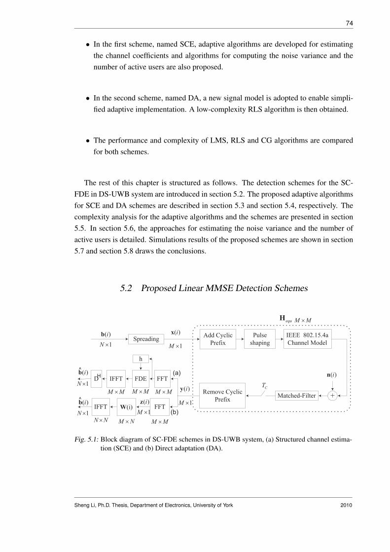
74
• In the first scheme, named SCE, adaptive algorithms are developed for estimatingthe channel coefficients and algorithms for computing the noise variance and thenumber of active users are also proposed.
• In the second scheme, named DA, a new signal model is adopted to enable simpli-fied adaptive implementation. A low-complexity RLS algorithm is then obtained.
• The performance and complexity of LMS, RLS and CG algorithms are comparedfor both schemes.
The rest of this chapter is structured as follows. The detection schemes for the SC-FDE in DS-UWB system are introduced in section 5.2. The proposed adaptive algorithmsfor SCE and DA schemes are described in section 5.3 and section 5.4, respectively. Thecomplexity analysis for the adaptive algorithms and the schemes are presented in section5.5. In section 5.6, the approaches for estimating the noise variance and the number ofactive users is detailed. Simulations results of the proposed schemes are shown in section5.7 and section 5.8 draws the conclusions.
5.2 Proposed Linear MMSE Detection Schemes
^
1N ´
FFT
M M´M N´
( )iz
1M ´
IFFT
N N´
(i)W
^( )ib
1N ´
( )ib ( )ix
1M ´
( )iy
1M ´
( )in
IEEE 802.15.4a
Channel Model
Add Cyclic
Prefix
Pulse
shaping
equH M M´
Spreading
Matched-Filter +
CT
Remove Cyclic
Prefix
(a)
(b)
M M´
FFT
M M´
IFFT FDE
h
D
M M´
1N ´
( )ibH
Fig. 5.1: Block diagram of SC-FDE schemes in DS-UWB system, (a) Structured channel estima-tion (SCE) and (b) Direct adaptation (DA).
Sheng Li, Ph.D. Thesis, Department of Electronics, University of York 2010

75
5.2.1 Problem Statement
After the DFT, the frequency domain detectors are implemented to recover the originaldata vector from the received signal that is shown in (2.12) As shown in Fig.5.1, wepropose two detection schemes, named SCE and DA, respectively. The SCE schemeexplicitly performs the channel estimation in the frequency domain, the detection withthe estimated channel coefficients, and finally carries out despreading in the time domain.The DA scheme implicitly estimates the channel and suppresses the ISI and MAI togetherwith only one filter and has a simpler structure than the SCE scheme. Without loss ofgenerality, we consider user 1 as the desired user and bypass the subscript of this user forsimplicity.
We define the estimated signal as b(i) and the final recovered signal as br(i). Hence,for the SCE scheme, the recovered signal can be expressed as
br(i) = sign(<(b(i)) = sign(<(DHFHCHz(i))), (5.1)
where(·)H denotes the Hermitian transpose, sign(·) is the algebraic sign function and<(·)represents the real part of a complex number. C denotes the frequency domain equalizer.The despreading is denoted as DH which can be considered as the Hermitian transposeof the spreading matrix.
For the DA scheme, the final recovered signal can be expressed as
br(i) = sign(<(b(i)) = sign(<(FHNWHz(i))), (5.2)
where W represents the frequency domain filter that is in an M -by-N matrix form. FN
is the N -by-N DFT matrix. In this scheme, the channel estimation and the despreadingis fulfilled implicitly together in the filter W.
In what follows, the MMSE designs of the matrix C in the SCE scheme and the W
in the DA scheme will be detailed. In general, these two detection schemes are basedon the same MMSE problem which aims at minimizing E[‖b(i) − b(i)‖2], but they usedifferent approaches to perform linear detection. For each scheme, some simplificationsand approximations for the later adaptive implementations will also be presented.
Sheng Li, Ph.D. Thesis, Department of Electronics, University of York 2010

76
5.2.2 Detector with Structured Channel Estimation (SCE)
The block diagram of the detector with SCE is shown as the branch (a) in Fig.5.1.Expanding (2.12), we have
z(i) = FHequ
K∑
k=1
xk(i) + Fn(i) = FHequFHF
K∑
k=1
xk(i) + Fn(i), (5.3)
Bearing in mind the circulant Toeplitz form of the equivalent channel matrix, we have adiagonal matrix
ΛH = FHequFH , (5.4)
whose a-th diagonal entry can be expressed as ha =∑L−1
l=0 hlexp{−j(2π/M)al}. Let usexpress it in a more convenient matrix form as
h =√
MFM,Lhequ, (5.5)
where h = [h0, h1, . . . , hM−1]T is called frequency domain CIR and FM,L is an M -by-L
matrix that is structured with the first L columns of the DFT matrix F. In order to simplifythe expression of this scheme in later adaptive developments, we include the constant
√M
into the FM,L, that isFM,L ⇐=
√MFM,L. (5.6)
The equations (5.5) and (5.6) are important for the development of the adaptive al-gorithms in the SCE scheme which will be detailed later. Here, we develop the MMSEdetector C to minimize the following cost function
JMSE−SCE(i) = E[∥∥b(i)−DHFHCHz(i))
∥∥2]. (5.7)
Substituting (5.3) and (5.4) into (5.7) and assuming that the noise sequence and the signalsequences are uncorrelated to each other, we can obtain the expression of the detector as
CMMSE =(ΛHFDallD
HallF
HΛHH + σ2IM
)−1ΛH, (5.8)
where the M -by-NK block diagonal matrix Dall contains the information of the spread-ing codes for all the users and can be expressed as
Dall =
s1 . . . sK
s1 . . . sK
. . .
s1 . . . sK
. (5.9)
Sheng Li, Ph.D. Thesis, Department of Electronics, University of York 2010

77
For the adaptive implementation, the downlink terminal usually does not have the in-formation of the spreading codes of other users. Hence, in this work, we adopted theapproximation DallD
Hall ≈ (K/Nc)IM for the development of the adaptive algorithms.
This approximation can also lead to a diagonal MMSE detector that can be considered asa sub-optimal solution [71]
C =
(K
Nc
ΛHΛHH + σ2
eIM
)−1
ΛH. (5.10)
From the expression of (5.10), it is clear that the remaining tasks of the SCE schemefor the adaptive implementation are to estimate the channel coefficients h, the noise vari-ance σ2
e and the number of active users K. The proposed algorithms for estimating theseparameters will be presented in later sections.
5.2.3 Detector with Direct Adaptation (DA)
The block diagram of the DA scheme is shown as the branch (b) in Fig.5.1. Thisscheme has much simpler system structure than the SCE scheme. However, if we godirectly with the signal model used for the SCE scheme, the resulting adaptive filter forDA schemes will be in an M -by-N matrix form which means very high complexity.Thanks to the new signal model proposed in [68], we can explore the structure of theMMSE detector in SC-FDE systems more efficiently. In this work, we adopt this newsignal model and extend it to simplify the design of the adaptive filters. It will be clearsoon how the new signal model we adopted can significantly reduce the complexity of theadaptive filter implementation in the DA scheme.
Firstly, we can express the transmitted signal from the k-th user as
xk(i) = Skbk,e(i), (5.11)
where the M -by-M (M = N × Nc) spreading matrix Sk has a circulant Toeplitz formas [68]
Sk =
sk(1) sk(2)
sk(2) sk(1)...
... sk(2) sk(Nc)
sk(Nc)...
. . .
sk(Nc). . .. . .
sk(1)
,
Sheng Li, Ph.D. Thesis, Department of Electronics, University of York 2010

78
The equivalent M -dimensional expanded data vector is
bk,e(i) = [bk(1),0Nc−1, bk(2),0Nc−1, · · · , bk(N),0Nc−1]T ,
where (·)T is the transpose. Hence, with the new signal model, the frequency domainreceived signal becomes
z(i) = Fy(i) =K∑
k=1
FHequSkbk,e(i) + Fn(i), (5.12)
Since both Hequ and Sk are circulant Toeplitz matrices, their product also has the circulantToeplitz form. This feature makes Λk = FHequSkF
H a diagonal matrix. Hence, we have
z(i) =K∑
k=1
FHequSkFHFbk,e(i) + Fn(i) =
K∑
k=1
ΛkFbk,e(i) + Fn(i). (5.13)
We can further expand Fbk,e(i) as [68]
Fbk,e(i) = (1/√
Nc)IeFNbk(i), (5.14)
where FN denotes the N -by-N DFT matrix and the M -by-N matrix Ie are structured as
Ie = [IN , · · · , IN︸ ︷︷ ︸Nc
]T . (5.15)
where IN denotes the N -by-N identity matrix. Finally, the frequency domain receivedsignal z(i) is expressed as
z(i) =K∑
k=1
(1/√
Nc)ΛkIeFNbk(i) + Fn(i). (5.16)
In the DA scheme, an M -by-N MMSE filter W(i) can be developed via the followingcost function:
JMSE−DA(i) = E[∥∥b(i)− FH
NWH(i)z(i)∥∥2
]. (5.17)
The MMSE solution of (5.17) is
WMMSE = R−1P, (5.18)
Sheng Li, Ph.D. Thesis, Department of Electronics, University of York 2010

79
where
R = E[z(i)zH(i)] = (1/Nc)K∑
k=1
ΛkIeIHe ΛH
k +σ2I; P = E[z(i)bH(i)] = (1/√
Nc)ΛkIe.
(5.19)Expanding (5.18), the MMSE solution can be expressed as
WMMSE =
(1
Nc
K∑
k=1
ΛkIeIHe ΛH
k + σ2I
)−1
ΛkIe√Nc
= VIe, (5.20)
where the M -by-M matrix V is
V =1√Nc
(1
Nc
K∑
k=1
ΛkIeIHe ΛH
k + σ2I
)−1
Λk. (5.21)
Note that the matrix V can be expressed as Nc-by-Nc block matrices vij , i, j ∈ {1, Nc},each vij is a N -by-N diagonal matrix. Hence, we take a closer look at the product of V
and Ie:
VIe =
v1,1 v1,2 . . . v1,Nc
v2,1 v2,2 . . . v2,Nc
......
......
vNc,1 vNc,2 . . . vNc,Nc
IN
IN
...IN
=
∑Nc
j=1 v1,j∑Nc
j=1 v2,j
...∑Nc
j=1 vNc,j
=
w1
w2
. . .
wNc
IN
IN
...IN
= WIe,
(5.22)
where wi =∑Nc
j=1 vi,j , i = 1, . . . , Nc, are diagonal matrices. Hence, the product of V
and Ie can be converted into a product of a M -by-M (M = N ×Nc) diagonal matrix W
and Ie, where the entries of W are wl, l = 1, . . . , M , equals the sum of all entries in thel-th row of matrix V. Finally, we express the MMSE design as
WMMSE = WIe = diag(we)Ie, (5.23)
where we = (w1, w2, . . . , wM) is an equivalent filter with M taps.
The design of the MMSE filter in DA scheme can be expressed as either in (5.18)or (5.23). We remark that the expression shown in (5.23) enables us to design an M -dimensional adaptive filter rather than an M -by-N matrix form adaptive filter to esti-mate the MMSE solution. This simplification significantly reduced the complexity of this
Sheng Li, Ph.D. Thesis, Department of Electronics, University of York 2010

80
scheme.
5.3 Adaptive Algorithms for SCE
In this section, we develop the LMS, RLS and CG adaptive algorithms for the fre-quency domain channel estimation in multiuser DS-UWB communications.
5.3.1 SCE-LMS
Substituting (5.5) and (5.6) into (5.3) and defining a diagonal matrix Xa(i) =
diag[F∑K
k=1 xk(i)], the rearranged frequency domain received signal becomes
z(i) = Xa(i)h + Fn(i) = Xa(i)FM,Lhequ + Fn(i). (5.24)
In the SCE, we take into account the fact that the length of the equivalent CIR hequ
is typically smaller than the received signal size [72]. For example, we assume that theDS-UWB channel in the time domain has 100 sample-spaced taps. This length of thestandard channel contains more than 85 percent of the total energy and can be consideredas an upper bound of the channel length. In the scenario where the received signal hasa length of M = 256 chips and we assume that each chip was sampled 3 times, hencethe length of the hequ is equal to L = 34 chips that is much smaller than M . As shownin (5.5), we can estimate the L-dimensional vector hequ rather than the M -dimensionalvector h. The SCE-LMS aims at minimizing the MSE cost function
JSCE−LMS(hequ(i)) = E[||z(i)−X(i)FM,Lhequ(i)||2], (5.25)
where the frequency domain received signal z(i) is shown in (5.24) and X(i) =
diag[Fx(i)], x(i) is the pilot signal from the desired user. The gradient of (5.25) withrespect to hequ(i) is
gh(i) = −E[FHM,LX
H(i)z(i)] + E[FHM,LX
H(i)X(i)FM,L]hequ(i), (5.26)
This leads to the SCE-LMS algorithm
hequ(i + 1) = hequ(i) + µhFHM,LX
H(i)eh(i), (5.27)
Sheng Li, Ph.D. Thesis, Department of Electronics, University of York 2010

81
where eh(i) = z(i) − X(i)FM,Lhequ(i) denotes the L-dimensional error vector and theconstant µh is the step size of the SCE-LMS algorithm.
5.3.2 SCE-RLS
The SCE-RLS algorithm is developed to minimize the least squares (LS) cost function
JSCE−RLS(hequ(i)) =i∑
j=1
λi−jh
∣∣∣∣∣∣z(j)−X(j)FM,Lhequ(i)
∣∣∣∣∣∣2
, (5.28)
where λh is the forgetting factor. Computing the gradient of (5.28) with respect to hequ(i)
and setting it to zero, the LS solution is
hequ,LS(i) = R−1h (i)ph(i) (5.29)
where
Rh(i) =i∑
j=1
λi−jh FH
M,LXH(j)X(j)FM,L ; ph(i) =
i∑j=1
λi−jh FH
M,LXH(j)z(j).
Note that there is an inversion of an L-by-L matrix Rh(i) in this solution. The matrixRh(i) can be computed in a recursive way via the recursion
Rh(i) = λhRh(i− 1) + FHM,LX
H(i)X(i)FM,L. (5.30)
There is no recursive way to simplify the inversion of this matrix and hence, we apply theadaptation equation shown in [72], that is
hequ(i + 1) = hequ(i) + R−1h (i)FH
M,LXH(i)eh(i), (5.31)
where eh(i) = z(i)−X(i)FM,Lhequ(i) is the M -dimensional error vector. For the L-by-Lmatrix Rh(i) , computing its inverse matrix with Gauss-Jordan elimination requires L3 ofcomplex multiplications [80]. This problem makes the SCE-RLS a high complexity al-gorithm and for this reason the performance of the RLS algorithm has not been discussedin [72]. For this paper, our goal is to implement this approach and assess its performanceagainst the performance of the proposed SCE-CG algorithm.
Sheng Li, Ph.D. Thesis, Department of Electronics, University of York 2010

82
5.3.3 SCE-CG
The SCE-CG aims at minimizing the MSE cost function
JSCE−CG(hequ(i)) = E[||z(i)−X(i)FM,Lhequ(i)||2], (5.32)
where the frequency domain input signal z(i) is shown in (5.24) and X(i) = diag[Fx(i)],x(i) is the pilot signal from the desired user. The instantaneous estimate of the gradientof (5.32) with respect to hequ(i) is
gh(i) = −FHM,LX
H(i)eh(i), (5.33)
where eh(i) = z(i) − X(i)FM,Lhequ(i) denotes the error vector. For each input datavector, a number of iterations is required for the CG method. Let us denote the iterationindex as c. For the (c + 1)-th iteration, the estimated hequ(i) is updated as
hequ,c+1(i) = hequ,c(i) + αh,c(i)dh,c(i), (5.34)
where αh,c(i) is the optimum step size and dh,c(i) is the direction vector for the c-thiteration. With the new estimator hequ,c+1(i), the error vector is updated as
eh,c+1(i) = z(i)−X(i)FM,Lhequ,c+1(i)
= eh,c(i)− αh,c(i)X(i)FM,Ldh,c(i).(5.35)
Since the direction vector dh,c(i) is orthogonal to the inverse gradient vector after the c-thiteration [28], we have
dHh,c(i)[−gh,c+1(i)] = 0, (5.36)
where gh,c+1(i)= −FHM,LX
H(i)eh,c+1(i).
Substituting (5.35) into (5.36), we obtain the expression for the optimum step size
αh,c(i) =−dH
h,c(i)gh,c(i)
dHh,cF
HM,LX
H(i)X(i)FM,Ldh,c(i). (5.37)
In the CG methods, the direction vector for each iteration can be obtained by
dh,c+1(i) = −gh,c+1(i) + βh,cdh,c(i), (5.38)
where the constant βh,c is determined to fulfill the convergence requirement for the di-rection vectors that these vectors are mutually conjugate [27], [28], [31]. We adopt the
Sheng Li, Ph.D. Thesis, Department of Electronics, University of York 2010

83
expression for βh,c as in [28]
βh,c =gH
h,c+1(i)gh,c+1(i)
−dHh,c(i)gh,c(i)
. (5.39)
Substituting (5.38) into the term dHh,c(i)gh,c(i) in (5.39) and taking the conjugate feature
of the direction vectors into account, that is dHh,c−1(i)gh,c(i) = 0, we can find that
−dHh,c(i)gh,c(i) = gH
h,c(i)gh,c(i). (5.40)
We remark that the relationship obtained in (5.40) can reduce the complexity of the SCE-CG algorithm by O(cL), where c is the number of iterations and L is the length of theequivalent CIR. This is because we have to compute the scalar term gH
h,c+1(i)gh,c+1(i) in(5.39) for the c-th iteration. However, with the relationship shown in (5.40), this scalarterm can be used directly in the (c + 1)-th iteration to save the computation for the scalarterm −dH
h,c+1(i)gh,c+1(i).
For the SCE scheme, the CG algorithm has lower computational complexity than theRLS algorithm while performing better than the LMS algorithm.
The proposed adaptive algorithms for the SCE scheme are summarized in the firstcolumn of Table 5.1.
5.4 Adaptive Algorithms for DA
In this section, we develop the LMS, RLS and CG adaptive algorithms for the DAscheme with the new signal model presented in section 5.2.3. For multiuser block trans-mission systems, these techniques can be implemented with a simple receiver structure.
5.4.1 DA-LMS
With the expression in (5.23), we can estimate the data vector as
b(i) = FHNIH
e WH(i)z(i) = FHNIH
e Z(i)w(i), (5.41)
Sheng Li, Ph.D. Thesis, Department of Electronics, University of York 2010

84
Tab. 5.1: Adaptive Algorithms For The Proposed Frequency domain Detection Schemes
SCE-Scheme DA-Scheme
1. Initialization: 1. Initialization:hequ(1) = L-by-1 zero-vector w(1) = M -by-1 zero-vectorFor i = 1, 2, . . . For i = 1, 2, . . .
2.1 SCE-LMS 2.1 DA-LMSeh(i) = z(i)−X(i)FM,Lhequ(i) ew(i) = b(i)−Y(i)w(i)
hequ(i + 1) = hequ(i) + µhFHM,LX
H(i)eh(i) w(i + 1) = w(i) + µwYH(i)ew(i)
2.2 SCE-RLS 2.2 DA-RLSRh(i) = λhRh(i− 1) + FH
M,LXH(i)X(i)FM,L Rw(i) = λwRw(i− 1) + YH(i)Y(i)
eh(i) = z(i)−X(i)FM,Lhequ(i) eaw(i) = b(i)−Y(i)w(i)
hequ(i + 1) = hequ(i) + R−1h (i)FH
M,LXH(i)eh(i) w(i + 1) = w(i) + R−1
w (i)YH(i)eaw(i).
2.3 SCE-CG 2.3 DA-CGSTEP 1: Initialization for iterations STEP 1: Initialization for iterationshequ,0(i) = hequ(i), w0(i) = w(i),eh,0(i) = z(i)−X(i)FM,Lhequ,0(i), ew,0(i) = b(i)−Y(i)w0(i),dh,0(i) = −gh,0(i) = FH
M,LXH(i)eh,0(i). dw,0(i) = −gw,0(i) = YH(i)ew,0(i).
For c = 0, 1, 2, . . . , (cmax − 1) For c = 0, 1, 2, . . . , (cmax − 1)
STEP 2: Update the channel estimation: STEP 2: Update the filter weights:αh,c(i) =
gHh,c(i)gh,c(i)
dHh,cF
HM,LXH(i)X(i)FM,Ldh,c(i)
, αw,c(i) =gHw,c(i)gw,c(i)
dHw,cY
H(i)Y(i)dw,c(i),
hequ,c+1(i) = hequ,c(i) + αh,c(i)dh,c(i), wc+1(i) = wc(i) + αw,c(i)dw,c(i),eh,c+1(i) = eh,c(i)− αh,c(i)X(i)FM,Ldh,c(i), ew,c+1(i) = ew,c(i)− αw,c(i)Y(i)dw,c(i),gh,c+1(i) = −FH
M,LXH(i)eh,c+1(i). gw,c+1(i) = −YH(i)ew,c+1(i).
STEP 3: Adapt the direction vector: STEP 3: Adapt the direction vector:βh,c =
gHh,c+1(i)gh,c+1(i)
gHh,c(i)gh,c(i)
, βw,c =gHw,c+1(i)gw,c+1(i)
gHw,c(i)gw,c(i)
,
dh,c+1(i) = −gh,c+1(i) + βh,cdh,c(i). dw,c+1(i) = −gw,c+1(i) + βw,cdw,c(i).
hequ(i + 1) = hequ,cmax(i). w(i + 1) = wcmax(i)
3. Estimate the data vector 3. Estimate the data vectorΛH(i) = diag
(FM ,Lhequ(i)
),
C(i) =(
KNc
ΛH(i)ΛHH (i) + σ2
eIM
)−1
ΛH br(i) = sign(<(Y(i)w(i))).
br(i) = sign(<(DHFHC(i)z(i))).
Sheng Li, Ph.D. Thesis, Department of Electronics, University of York 2010
85
where Z(i) = diag(z(i)) and w(i) = w∗e(i) is the adaptive filter weight vector. Since FN
and Ie are fixed, we consider the equivalent N -by-M received data matrix as
Y(i) = FHNIH
e Z(i), (5.42)
and express the estimated data vector as
b(i) = Y(i)w(i). (5.43)
Hence, the cost function for developing the DA-LMS algorithm can be expressed as
JDA−LMS(w(i)) = E[||b(i)−Y(i)w(i)||2]. (5.44)
The gradient of (5.44) with respect to w(i) is
gw(i) = −E[YH(i)b(i)] + E[YH(i)Y(i)]w(i).
Using the instantaneous estimates of the expected values in the gradient, we obtain theDA-LMS as
w(i + 1) = w(i) + µwYH(i)ew(i), (5.45)
where ew(i) = b(i)−Y(i)w(i) is the N -dimensional error vector and µw is the step sizefor DA-LMS.
5.4.2 DA-RLS
The DA-RLS algorithm is developed to minimize the least square (LS) cost function
JDA−RLS(w(i)) =i∑
j=1
λi−jw
∣∣∣∣b(j)−Y(j)w(i)∣∣∣∣2, (5.46)
where λw is the forgetting factor. Computing the gradient of (5.46) with respect to w(i)
and setting it to zero, the LS solution is
wLS(i) = R−1w (i)pw(i), (5.47)
where Rw(i) =∑i
j=1 λi−jw YH(j)Y(j) and pw(i) =
∑ij=1 λi−j
w YH(j)b(j). We can ex-press the M -by-M (where M = NNc) matrix Rw(i) and the M -dimensional vector pw(i)
recursively asRw(i) = λwRw(i− 1) + YH(i)Y(i), (5.48)
Sheng Li, Ph.D. Thesis, Department of Electronics, University of York 2010
86
pw(i) = λwpw(i− 1) + YH(i)b(i). (5.49)
With the expression of the received data matrix shown in (5.42), we can explore the struc-ture of the matrix Rw(i), since
YH(i)Y(i) = ZH(i)IeFNFHNIH
e Z(i) = ZH(i)(IeI
He
)Z(i), (5.50)
the M -by-M sparse matrix(IeI
He
)is structured with Nc-by-Nc block matrices and each
block matrix is an N -by-N identity matrix. Bearing in mind that the matrix Z(i) is adiagonal matrix, we conclude that Rw(i) is an M -by-M symmetric sparse matrix whichconsists of Nc-by-Nc block matrices and each block matrix is an N -by-N diagonal ma-trix. The number of nonzero elements in Rw(i) equals MNc. With Gauss-Jordan elimi-nation [80], the inversion of each N -by-N diagonal matrix has the complexity O(N) andthe inversion of Nc-by-Nc such block matrices requires the complexity O(NN3
c ), whichequals O(MN2
c ). Hence, for the single user case, where Nc = 1, the complexity ofcomputing R−1
w (i) is only O(M). In addition, equation (5.50) shows that the complex-ity of the recursion to obtain Rw(i) is low. Since the matrix
(IeI
He
)can be pre-stored at
the receiver, for each time instant, the computation complexity to obtain Rw(i) is onlyO(MNc). With these properties, we can investigate a low-complexity RLS algorithmto update the filter vector recursively. In order to obtain such a recursion, we apply themethod that is proposed in the appendix B in [72]. We have the relationship
Rw(i)w(i + 1) = pw(i). (5.51)
Replacing w(i + 1) with [w(i + 1)− w(i) + w(i)] in (5.51) and using (5.48) and (5.49)obtains
Rw(i)[w(i+1)− w(i)]+ [λwRw(i−1)+YH(i)Y(i)]w(i) = λwpw(i−1)+YH(i)b(i).
(5.52)Since Rw(i− 1)w(i) = pw(i− 1), (5.52) becomes
Rw(i)[w(i + 1)− w(i)] = YH(i)eaw(i), (5.53)
where eaw(i) = b(i)−Y(i)w(i) is the N -dimensional error vector. Finally, the recursionfor updating the filter vector is
w(i + 1) = w(i) + R−1w (i)YH(i)eaw(i). (5.54)
We remark that the DA-RLS only consists of (5.48) and (5.54). The complexity of thisalgorithm is only O(MN2
c ), which is comparable to the DA-CG in multiuser scenariosand for the single user scenario where Nc = 1, it reduces to the level of the DA-LMS.
Sheng Li, Ph.D. Thesis, Department of Electronics, University of York 2010

87
5.4.3 DA-CG
The cost function for developing a CG algorithm for the DA scheme can be expressedas
JDA−CG(w(i)) = E[||b(i)−Y(i)w(i)||2]. (5.55)
The gradient of (5.55) with respect to w(i) is
gw(i) = −E[YH(i)b(i)] + E[YH(i)Y(i)]w(i).
We can use the instantaneous estimates of the expected values and obtain an estimate ofthe gradient vector as
gw(i) = −YH(i)ew(i), (5.56)
where ew(i) = b(i) − Y(i)w(i) is the error vector. Here, we also define the iterationindex as c. For the (c + 1)-th iteration, the error vector is
ew,c+1(i) = b(i)−Y(i)wc+1(i), (5.57)
where the filter weight vector is updated as
wc+1(i) = wc(i) + αw,c(i)dw,c(i), (5.58)
where dw,c(i) is the direction vector at the c-th iteration. The step size αw,c(i) is deter-mined to minimize the cost function (5.55) [28], [31]. Substituting (5.58) in (5.57), theerror vector can be expressed as
ew,c+1(i) = ew,c(i)− αw,c(i)Y(i)dw,c(i). (5.59)
Since the direction vector dw,c(i) is orthogonal to the inverse gradient vector after the c-thiteration [28], we have dH
w,c(i)[−gw,c+1(i)] = 0, where gw,c+1(i) = −YH(i)ew,c+1(i).Hence, from (5.59), the optimum step size is
αw,c(i) =−dH
w,c(i)gw,c(i)
dHw,cY
H(i)Y(i)dw,c(i). (5.60)
The adaptation equation for the direction vector can be expressed as
dw,c+1(i) = −gw,c+1(i) + βw,cdw,c(i), (5.61)
where the constant βw,c is determined to fulfill the convergence requirement for the di-rection vectors that these vectors are mutually conjugate [27], [28], [31]. We adopt the
Sheng Li, Ph.D. Thesis, Department of Electronics, University of York 2010

88
Tab. 5.2: Complexity analysis for the frequency domain adaptive algorithms
Algorithm Complex Additions Complex Multiplications
SCE-LMS 2ML 2ML + 2M + LSCE-RLS 2L3 + 2ML− 2L2 2L3 + 3ML + (2 + M)L2
SCE-CG (2ML + M + 3L− 3)c (2ML + 4M + 4L + 1)c
DA-LMS 2MN 2MN + NDA-RLS M(N2
c + 2Nc + 2N − 2) M(N2c + 6Nc + 2N − 1)
DA-CG (2MN + 2M − 2)c (2MN + 2M + N + 2)c
expression for βw,c as in [28]
βw,c =gH
w,c+1(i)gw,c+1(i)
−dHw,c(i)gw,c(i)
, (5.62)
If we substitute (5.61) into the term dHw,c(i)gw,c(i) in (5.62) and take the conjugate feature
of the direction vectors into account, we can find that
−dHw,c(i)gw,c(i) = gH
w,c(i)gw,c(i). (5.63)
As explained for (5.40), the relationship obtained in (5.63) can save the computationalcomplexity by O(cM) for the DA-CG algorithm, where c is the number of iterations andM is the length of the received signal.
The proposed adaptive algorithms for the DA scheme are summarized in the secondcolumn of Table 5.1.
5.5 Complexity Analysis
In this section, we discuss the complexity of the proposed adaptive algorithms and thedetection schemes.
Table 5.2 shows the complexity for the proposed algorithms with respect to the numberof complex additions and complex multiplications for each time instant, where M is thelength of the received signal, N is the length of the data block and L is the length of theequivalent CIR. For the CG algorithms, the iteration number is denoted as c, which ismuch smaller than M , say M = 256, c = 8. In this work, the complexity of the FFT andIFFT, which is O(M log2M ), is common to all the techniques and is not shown in thistable.
Sheng Li, Ph.D. Thesis, Department of Electronics, University of York 2010

89
It is important to note that for the adaptive algorithms in the SCE scheme, the com-plexity is determined by M and L, while in the DA scheme it is determined by M andN , bearing in mind that the spreading gain Nc equals M/N . Hence, we compare thecomplexity of the algorithms with the system parameters that will be used in the simu-lation section, say L = 34 and N = 32, with different spreading gain Nc (which leadsto different received signal length M , since M = NcN ). Fig. 5.2 shows the numberof complex multiplications for adaptive algorithms versus different spreading gains. Thecomplexity of the CG algorithms with iteration number of 2 and 8 are shown in this figurefor comparison. With these system parameters, the SCE-LMS has a similar complexityto the DA-LMS, and the SCE-CG has a similar complexity to the DA-CG. However, theSCE-RLS is the most complex adaptive algorithm while the DA-RLS has much lowercomplexity. For the SCE scheme, the SCE-CG algorithm is significantly simpler than theSCE-RLS. It will be illustrated by the simulation results that with 8 iterations, the per-formance of the SCE-CG algorithm is very close to the SCE-RLS. For the DA scheme,in the single user scenario where Nc = 1, the DA-RLS has the same complexity level asthe DA-LMS. In the multiuser case, the complexity of the DA-RLS is comparable to theDA-CG. With small spreading gains, the DA-RLS has lower complexity than the DA-CGwith only 2 iterations. However, the complexity of the DA-RLS will be boosted whenthe spreading gain increases. It will be illustrated by simulations that the performance ofthe DA-CG is comparable to the DA-RLS, hence, for multiuser scenarios with differentvalues of Nc, the designer can choose either RLS or CG for the DA scheme.
After discussing the complexity of the adaptive algorithms, let us consider the com-plexity of the detection schemes. For the DA scheme, where only one adaptive filteris implemented and the complexity shown in Table 5.2 can be considered as the wholescheme’s complexity. However, for the SCE scheme, the complexity shown in the table isonly for the adaptive channel estimation. The complexity of estimating the noise varianceO(ML2), the number of active usersO(M), performing the MMSE detectionO(M) andthe time domain despreading O(N2) should also be included. Hence, we conclude thatthe DA scheme is simpler than the SCE scheme in both structure and the computationalcomplexity. However, the SCE scheme, which will be shown later, has better performancethan the DA scheme.
5.6 Noise Variance and Number of Active Users Estimation
For the SCE scheme, the MMSE detector is generated as (5.10), which requires theknowledge of the noise variance σ2
e and the number of active users K. In this section,
Sheng Li, Ph.D. Thesis, Department of Electronics, University of York 2010

90
2 4 6 8 10 1210
3
104
105
Num
ber
of C
ompl
ex M
ultip
licat
ions
Nc
DA−LMSSCE−LMSDA−BCGSCE−BCGDA−RLSSCE−RLS
c=2
c=8
Fig. 5.2: Complexity comparison of the proposed schemes for SC-FDE.
we propose an ML estimation algorithm that extends [72] for estimating σ2e in the DS-
UWB system. We consider multiuser communication and the pilot sequence is generatedrandomly for each time instant.
The most popular active users number detection schemes for symbol by symbol trans-mission systems that are based on the eigenvalue decomposition have been proposedin [81]- [83]. These schemes have very high complexity and require high SNR to workin our block transmission system. In this work, we propose a simple approach to estimatethe number of users based on the idea that the power of the received signal will reflectthe number of active users. So firstly, we develop the relationship between the receivedsignal power, the noise variance, the estimated channel coefficients and the number ofactive users. Then we obtain a simple algorithm to estimate K with these relationships.
Sheng Li, Ph.D. Thesis, Department of Electronics, University of York 2010

91
5.6.1 Noise Variance Estimation
Revisiting (5.24), we have the frequency domain received signal as
z(i) = Xa(i)FM,Lhequ + Fn(i), (5.64)
where the diagonal matrix Xa(i) = diag[∑K
k=1 Fxk(i)]. We assume that the first useris the desired user and define X(i) = diag[Fx(i)]. The uncorrelated additive noise isassumed to be Gaussian distributed with zero mean and variance of σ2
e . The ML estimatoraims at estimating σ2
e(i) and hequ(i) by maximizing the log-likelihood function, that is
[σ2
e(i), hequ(i)]
= arg maxσ2
e(i),hequ(i)Λ(σ2
e(i),hequ(i)), (5.65)
where
Λ(σ2e(i),hequ(i)) = −M ln(σ2
e(i))−‖z(i)−B(i)hequ(i)‖2
σ2e(i)
, (5.66)
where B(i) = X(i)FM,L. To solve this joint optimization problem, we firstly fix σ2e(i)
and find the optimum hequ(i). By calculating the gradient of (5.66) with respect to hequ(i)
and setting it to zero, we obtain
hequ,ML(i) =(BH(i)B(i)
)−1BH(i)z(i). (5.67)
Substituting (5.67) into (5.66), and calculating the gradient of (5.66) with respect to σ2e(i)
and setting it to zero, we obtain the ML estimate of σ2e(i)
σ2e,ML(i) =
1
M
∥∥∥z(i)−B(i)hequ,ML(i)∥∥∥
2
. (5.68)
In the training stage of the SCE scheme, we estimate the noise variance via (5.67) and(5.68), where the number of complex multiplications required is ML2 + L3 + 2ML +
L2 + M + 1. The cost of this estimator is high and it is possible to obtain a simplifiedestimate with the complexity of O(ML) by replacing the ML estimate hequ,ML(i) withthe estimated channel hequ(i) that is obtained in section 5.3. However, this will introducenoticeable degradation of the estimation performance in multiuser scenarios. Since in ourSCE scheme, the noise variance estimator is used for both users number estimation andthe MMSE detection, the degradation of the σ2 will affect the final performance.
Sheng Li, Ph.D. Thesis, Department of Electronics, University of York 2010

92
5.6.2 Number of Active Users Estimation
In order to obtain the relationship of the active users number and the received signalpower, let us consider the expected value of the frequency domain received signal power
E[zH(i)z(i)] = E
[(Xa(i)h + Fn(i)
)H (Xa(i)h + Fn(i)
)]
= hHE[XHa (i)Xa(i)]h + σ2
eM,
(5.69)
where z(i) is shown in (5.24). Since the M -by-M diagonal matrix Xa(i) =
diag[F∑K
k=1 xk(i)], the l-th entry of the main diagonal can be expressed as
Xa,l(i) = Fl
K∑
k=1
xk(i), (5.70)
where l = 1, 2, . . . , M and Fl is the l-th row of the DFT matrix F. Bearing in mind thefact that FlF
Hl = 1. Hence, the expected entry in (5.69) can be expressed as
E[XHa (i)Xa(i)] = diag
(E[X2
a,1 , X2a,2 , . . . , X2
a,M ]), (5.71)
where
E[X2
a,l
]= E
Fl
(K∑
k=1
xk(i)
)(K∑
k=1
xk(i)
)H
FHl
= E[FlDallD
HallF
Hl
] ≈ K
Nc
,
(5.72)
where Dall is shown in (5.9) and the approximation used here is the same as in (5.10), thatis DallD
Hall ≈ (K/Nc)IM.
Finally, substituting (5.71) into (5.69) with the approximation shown in (5.72), weobtain the relationship which can be expressed as
E[zH(i)z(i)] ≈ K
Nc
hHh + σ2eM, (5.73)
where K is the number of active users, σ2e is the noise variance and h is the frequency
domain channel coefficients. In this work, we have already obtained the estimator for σ2e
and hequ. The expected received signal power can be estimated via time-averaging, thatis
Pr(i) =1
T
T∑i=1
zH(i)z(i). (5.74)
Sheng Li, Ph.D. Thesis, Department of Electronics, University of York 2010
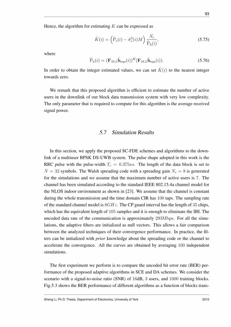
93
Hence, the algorithm for estimating K can be expressed as
K(i) =(Pr(i)− σ2
e(i)M) Nc
Ph(i), (5.75)
wherePh(i) = (FM,Lhequ(i))
H(FM,Lhequ(i)). (5.76)
In order to obtain the integer estimated values, we can set K(i) to the nearest integertowards zero.
We remark that this proposed algorithm is efficient to estimate the number of activeusers in the downlink of our block data transmission system with very low complexity.The only parameter that is required to compute for this algorithm is the average receivedsignal power.
5.7 Simulation Results
In this section, we apply the proposed SC-FDE schemes and algorithms to the down-link of a multiuser BPSK DS-UWB system. The pulse shape adopted in this work is theRRC pulse with the pulse-width Tc = 0.375ns. The length of the data block is set toN = 32 symbols. The Walsh spreading code with a spreading gain Nc = 8 is generatedfor the simulations and we assume that the maximum number of active users is 7. Thechannel has been simulated according to the standard IEEE 802.15.4a channel model forthe NLOS indoor environment as shown in [23]. We assume that the channel is constantduring the whole transmission and the time domain CIR has 100 taps. The sampling rateof the standard channel model is 8GHz. The CP guard interval has the length of 35 chips,which has the equivalent length of 105 samples and it is enough to eliminate the IBI. Theuncoded data rate of the communication is approximately 293Mbps. For all the simu-lations, the adaptive filters are initialized as null vectors. This allows a fair comparisonbetween the analyzed techniques of their convergence performance. In practice, the fil-ters can be initialized with prior knowledge about the spreading code or the channel toaccelerate the convergence. All the curves are obtained by averaging 100 independentsimulations.
The first experiment we perform is to compare the uncoded bit error rate (BER) per-formance of the proposed adaptive algorithms in SCE and DA schemes. We consider thescenario with a signal-to-noise ratio (SNR) of 16dB, 3 users, and 1000 training blocks.Fig.5.3 shows the BER performance of different algorithms as a function of blocks trans-
Sheng Li, Ph.D. Thesis, Department of Electronics, University of York 2010

94
0 200 400 600 800 1000
10−2
10−1
100
Number of Blocks
BE
R
DA−LMS(µ=0.075)SCE−LMS(µ=0.05)DA−RLS(λ=0.9998,δ=2)SCE−RLS(λ=0.9998,δ=10)DA−CG(c=8)SCE−CG(c=8)DA−MMSESCE−MMSE
Fig. 5.3: BER performance of the proposed SC-FDE detection schemes versus the number oftraining blocks for a SNR=16dB. The number of users is 3.
mitted. In this experiment, the knowledge of the number of users K and the noise varianceσ2
e are given for MMSE detection in the SCE scheme. It will be shown later, the perfectlyknown K and σ2
e does not produce significant improvements in the BER performancecompared with using the estimated values. In both schemes, with only 8 iterations, theproposed CG algorithms outperform the LMS algorithms and perform close to the RLSalgorithms. Since the filtering step in the SCE scheme which takes into the account thatL is smaller than M provides some performance gain, the adaptive algorithms in SCEscheme performs better than in the DA scheme. However, the DA scheme has simplerstructure and lower computational complexity. The MMSE curves are obtained with theknowledge of the channel, the spreading codes of all the users and the noise variance.It can be found that, the MMSE performances of the proposed schemes are exactly thesame. This is because these two schemes can be considered as two different approachesto solve the same MMSE problem.
Fig.5.4 shows the performances of the ML estimators of the noise variance in differentSNRs. For each SNR scenario, the estimated values of the noise variances for 1, 3 and 5
users are compared with the values in theory. For the multiuser case, the ML estimators
Sheng Li, Ph.D. Thesis, Department of Electronics, University of York 2010

95
0 5 10 15 20
10−2
10−1
100
SNR(dB)
Est
imat
ed σ
2
TheoryK=1K=3K=5
Fig. 5.4: Performance of the noise variance estimator.
are not very accurate in the high SNR environments. However, it will be demonstratedsoon by simulations that this inaccuracy will only lead to very limited BER performancereduction.
Fig.5.5 illustrates the performance of the estimators of the number of active users ina 16dB environment with SCE-CG algorithm and we consider the multiuser cases of 2to 4 users. The number of users is determined by the received signal power Pr(i), thenoise variance σ2
e(i) and the channel power Ph(i) as shown in (5.75). Firstly, we showthe performance of this estimator with the knowledge of σ2
e(i) and Ph(i). Because of anapproximation used in (5.73), the values of the estimated users number have gaps to thereal values. For example, in 2 and 3 users cases, these gaps are around 0.5 users. Secondly,we assess the performance of the users number estimator with the estimated noise varianceσ2
e(i) and the adaptive channel coefficients. It should be noted that the channel estimationis started with a null vector, which means very small Ph(i) at the beginning stage and thisleads to very large K. Hence, we set K = 7 as an upper maximum for this estimator.The estimated values of K approaches the curves which are obtained with the knowledgeof noise variance and the channel power. For the cases of 3 and 4 users, the curves fit
Sheng Li, Ph.D. Thesis, Department of Electronics, University of York 2010

96
0 200 400 600 800 1000 1200 14002
2.5
3
3.5
4
4.5
5
5.5
6
6.5
7
Number of Blocks
Est
imat
ed K
K=2, Estimated P
h and σ2
K=2, Perfect Ph and σ2
K=3, Estimated Ph and σ2
K=3, Perfect Ph and σ2
K=4, Estimated Ph and σ2
K=4, Perfect Ph and σ2
Fig. 5.5: Performance of the active users number estimator.
well but there is a mismatch when the users number is 2. This mismatch is caused bythe estimation errors of σ2
e(i) and Ph(i). However, later simulations will indicate that themismatches introduced by the approximation and the estimation errors will not noticeablyaffect the BER performance.
Fig.5.6 shows the uncoded BER performance of the proposed CG algorithms with dif-ferent number of iterations for each adaptation. For both schemes, the CG algorithms per-form better as the number of iterations increases. However, using more than 8 iterationswill only produce very limited improvement in the BER performance for both schemesbut increase significantly the computational complexity. In our system, a good choice forthe number of iterations is c = 8. In this figure, all the dotted curves for the SCE schemeare obtained with the knowledge of σ2
e and K. We also include a dashed curve to showthe performance of the SCE-CG with 8 iterations that is using the estimated values of σ2
e
and K. It is shown that using the estimated values will not affect the convergence rate butonly lead to a small reduction at the steady-state performance.
Fig.5.7 illustrates the uncoded BER performance of different algorithms in a scenario
Sheng Li, Ph.D. Thesis, Department of Electronics, University of York 2010
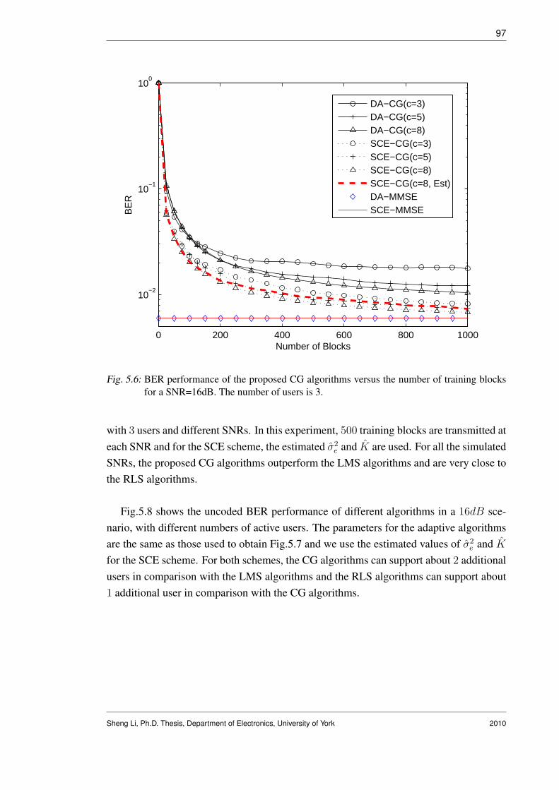
97
0 200 400 600 800 1000
10−2
10−1
100
Number of Blocks
BE
R
DA−CG(c=3)DA−CG(c=5)DA−CG(c=8)SCE−CG(c=3)SCE−CG(c=5)SCE−CG(c=8)SCE−CG(c=8, Est)DA−MMSESCE−MMSE
Fig. 5.6: BER performance of the proposed CG algorithms versus the number of training blocksfor a SNR=16dB. The number of users is 3.
with 3 users and different SNRs. In this experiment, 500 training blocks are transmitted ateach SNR and for the SCE scheme, the estimated σ2
e and K are used. For all the simulatedSNRs, the proposed CG algorithms outperform the LMS algorithms and are very close tothe RLS algorithms.
Fig.5.8 shows the uncoded BER performance of different algorithms in a 16dB sce-nario, with different numbers of active users. The parameters for the adaptive algorithmsare the same as those used to obtain Fig.5.7 and we use the estimated values of σ2
e and K
for the SCE scheme. For both schemes, the CG algorithms can support about 2 additionalusers in comparison with the LMS algorithms and the RLS algorithms can support about1 additional user in comparison with the CG algorithms.
Sheng Li, Ph.D. Thesis, Department of Electronics, University of York 2010

98
6 8 10 12 14 16 1810
−3
10−2
10−1
100
SNR(dB)
BE
R
DA−LMS(µ=0.075)
SCE−LMS(µ=0.05)
DA−RLS(λ=0.9998,δ=2)
SCE−RLS(λ=0.9998,δ=10)DA−CG(c=8)SCE−CG(c=8)DA−MMSESCE−MMSE
Fig. 5.7: BER performance of the proposed SC-FDE detection schemes versus the SNR. The num-ber of users is 3.
5.8 Conclusion
In this chapter, two adaptive detection schemes are proposed for the multiuser DS-UWB communications based on the SC-FDE. These schemes can be considered as twoapproaches to solve the MMSE detection problem in the block by block transmission SCsystems. The first scheme, named SCE, adaptively estimates the channel coefficients inthe frequency domain and then performs the detection and despreading separately. In ad-dition, the MMSE detection in SCE scheme requires the knowledge of the noise varianceand the number of active users. To this purpose, we proposed simple algorithms to es-timate these values. The second scheme, named DA, updates one filter in the frequencydomain to suppress both the MAI and the ISI. The DA scheme has a simpler structure anda lower complexity but the SCE scheme performs better. For both schemes, we devel-oped LMS, RLS and CG adaptive algorithms. For the SCE scheme, the CG algorithm hasmuch lower complexity than the RLS algorithm while performing better than the LMSalgorithm. For the DA scheme, a low complexity RLS algorithm is obtained which hasthe complexity comparable to the CG algorithm in the multiuser scenarios. In the single
Sheng Li, Ph.D. Thesis, Department of Electronics, University of York 2010
99
1 2 3 4 5 6 7
10−2
10−1
Number of Users
BE
R
DA−LMS(µ=0.075)
SCE−LMS(µ=0.05)
DA−RLS(λ=0.9998,δ=2)
SCE−RLS(λ=0.9998,δ=10)DA−CG(c=8)SCE−CG(c=8)DA−MMSESCE−MMSE
Fig. 5.8: BER performance of the proposed SC-FDE detection schemes versus number of Usersin the scenario with a 16dB SNR.
user system, the complexity of DA-RLS is reduced to the same level as the DA-LMS.
Sheng Li, Ph.D. Thesis, Department of Electronics, University of York 2010

6. ADAPTIVE PARAMETER ESTIMATION AND INTERFERENCESUPPRESSION WITH BIAS IN THE FREQUENCY DOMAIN
Contents6.1 Introduction . . . . . . . . . . . . . . . . . . . . . . . . . . . . . . . 100
6.2 Parameter Estimation . . . . . . . . . . . . . . . . . . . . . . . . . . 103
6.3 Interference Suppression . . . . . . . . . . . . . . . . . . . . . . . . 107
6.4 The Cramer-Rao Lower Bound and Its Extension . . . . . . . . . . 112
6.5 Simulations . . . . . . . . . . . . . . . . . . . . . . . . . . . . . . . . 114
6.6 Conclusion . . . . . . . . . . . . . . . . . . . . . . . . . . . . . . . . 119
6.1 Introduction
A common estimation problem in communications engineering is to estimate a pa-rameter vector from noisy observations. In this chapter, we consider the deterministicestimation problem with additive white Gaussian noise (AWGN) in two scenarios: pa-rameter estimation and interference suppression. In the parameter estimation scenario,the M -dimensional observation vector is given by y = Xh + n, where X is a givenM -by-L matrix and n is the M -dimensional vector that presents the AWGN with zeromean. The L-dimensional parameter vector h is the target parameter vector to be esti-mated. In the interference suppression scenario, the M -dimensional observation vectoris given by z = Hb + n, where H is an unknown M -by-N matrix that can representthe channel and/or the spreading codes and the M -dimensional vector n is the AWGN.Instead of given H, a training sequence is transmitted and an equalizer whose parametersare organized in the vector w is estimated to recover the N -dimensional date vector b.
A classical approach to solving these problems is the least-square (LS) method, whichwill lead to minimum variance unbiased estimators (MVUE) [84]. The unbiasness isusually considered as a good property for an estimator. Indeed, the unbiased estimatorswill obtain the true value of the unknown parameter on average [84]. However, in some

101
scenarios the LS method is not directly related to the MSE associated with the targetparameter vector and it has been found that a lower MSE can be achieved by addingan appropriately chosen bias to the conventional LS estimators [85]- [92]. The biasedestimation has shown its ability to outperform the existing estimators especially in thelow signal-to-noise ratios (SNR) and/or short data records [86].
In the parameter estimation scenario, the typical objective is to minimize the estima-tion error (h−h), rather than minimize the the Euclidian norm of the error (y−y), wherey = Xh is the transformed estimator [85]. Some biased estimators have been proposedto achieve a smaller estimation error than the LS solutions by removing the unbiased-ness of the conventional estimators with a shrinkage factor in the parameter estimationscenario. The earliest shrinkage estimators that reduce the MSE over MVUE include thewell known James-Stein estimator [87] and the work of Thompson [88]. Some extensionsof the James-Stein estimator have been proposed in [89]- [92]. In [93], blind minimaxestimation (BME) techniques have been proposed, in which the biased estimators weredeveloped to minimize the worst case MSE among all possible values of h within a pa-rameter set. If a spherical parameter set is assumed, the shrinkage estimator obtained isnamed spherical BME (SBME) [93].
For the interference suppression scenario, the LS solution of the equalizer is obtainedto minimize the Euclidian norm of the error (b− b) and results in an unbiased estimatorof w. In this scenario, biased estimators can be implemented to achieve lower estimationerror between w and w, which is a more accurate approach to estimate the equalizeritself. The shrinkage estimators thus are promising to perform better in the interferencesuppression scenario with short training data support and in long filter scenarios.
To the best of our knowledge, the shrinkage estimators are rarely implemented intoreal communication systems. One possible reason is that some assumptions required forthe signal model may not be found, for example, in the TH-UWB systems, the MAI can-not be accurately approximated by a Gaussian distribution for some values of SNR andSIR [94]- [95]. Another possible reason is that the existing shrinkage estimators usuallyrequire some statistical information such as the noise variance and the norm of the realparameter vector. In this chapter, we propose adaptive bias shrinkage estimators, whichdo not require this information and are able to improve the performance of the RLS adap-tive algorithms in the scenarios of parameter estimation and interference suppression. Theconsidered schemes corresponding to these scenarios are the RLS versions of the struc-tured channel estimation (SCE) and the direct adaptation (DA) in SC-FDE for DS-UWBsystems that are proposed in Chapter 5. With additional complexity that is linearly depen-dent on the filter size, considerable performance improvement can be obtained especially
Sheng Li, Ph.D. Thesis, Department of Electronics, University of York 2010

102
in the low SNR and short data support environments. In the parameter estimation sce-nario, the proposed biased estimator performs better than the conventional RLS-basedSCE in terms of the MSE between the estimated parameter vector and the true vector.Note that the SCE structure has some performance gain in comparison with the unstruc-tured channel estimation [72] and the RLS version of the SCE performs better than otheradaptive versions that are studied in Chapter 5.3. We remark that with the proposed biasedestimator, further improvement of the SCE-RLS is obtained in terms of MSE. In the in-terference suppression scenario, the proposed biased estimator brings some initializationgain for the DA-RLS scheme that is introduced in Chapter 5.4.2. The convergence of theDA-RLS scheme is accelerated because of the bias and a more accurate equalizer esti-mation is achieved. An extended CRLB is calculated to examine the MSE performanceof the proposed shrinkage biased estimators. A study of the proposed algorithms in thepresence of UWB signals is carried out.
The main contributions of this chapter are listed below.
• Shrinkage estimators are developed to improve the performance of the frequencydomain RLS algorithms in the applications of parameter estimation and interferencesuppression in DS-UWB systems.
• LMS based adaptive algorithms are developed in both scenarios to obtain theshrinkage factors.
• The biased CRLB that constitutes a fundamental estimation limit of the shrinkageestimators is calculated and we extend it to a lower bound for the MSE performanceof the shrinkage estimators.
• The performance of the proposed biased estimators are examined in SC-FDE ofDS-UWB systems with IEEE 802.15.4a channel model and severe ISI and MAI.
The rest of this chapter is structured as follows. Section 6.2 presents the LS solu-tion for the parameter estimation scenario and the proposed shrinkage estimator that canachieve a lower estimation error. Section 6.3 presents the LS solution for the interferencesuppression scenario and the proposed shrinkage estimator that is aiming to improve theperformance of the RLS algorithm with short data records. The biased CRLB is calculatedin Section 6.4. In Section 6.5, the proposed biased estimators are equipped in SC-FDE ofDS-UWB systems and the simulation results demonstrate their better performance thanthe RLS algorithms. Section 6.6 draws the conclusions.
Sheng Li, Ph.D. Thesis, Department of Electronics, University of York 2010

103
6.2 Parameter Estimation
In this section, the LS design for the parameter estimation scenario is detailed and theproposed shrinkage estimator is developed to improve the MSE performance of the LSsolution.
6.2.1 LS solution Parameter Estimation
The linear estimation problem we discussed in this section can be expressed as
y = Xh + n, (6.1)
where the M -by-L data matrix X and the M -dimensional received signal y are given, nis additive white Gaussian noise (AWGN) with zero mean and variance σ2. Note that, thestructured channel estimation (SCE) problem we solved in Chapter 5.3 is a typical exam-ple of the parameter estimation scenario. In such scenario, we are aiming at estimatingthe L-dimensional channel vector h based on the MMSE criterion. The MSE consists ofthe variance and the bias of the estimator, which can be expressed as
E[‖h− h‖2] = E[(h− E[h])H(h− E[h])] + E[‖E[h]− h‖2], (6.2)
For the unbiased estimators, the MSE becomes
E[‖h− hu‖2] = E[(hu − h)H(hu − h)] = var(h, hu), (6.3)
To solve the parameter estimation problem, the conventional LS channel estimationcan be obtained by minimizing the following cost function
JLS(h) = ‖y −Xh‖2, (6.4)
assuming that the matrix XHX is a full rank matrix, then the LS solution is given by
hLS = (XHX)−1XHy. (6.5)
Assuming the AWGN with zero mean and variance σ2, the LS estimator is an unbiased
Sheng Li, Ph.D. Thesis, Department of Electronics, University of York 2010

104
estimator because E[hLS] = h. Hence, the MSE for the LS estimator is
E[‖h− hLS‖2] = E[(hLS − h)H(hLS − h)] = var(h, hLS). (6.6)
Defining v = var(h, hLS), we have
v = E[(hLS − h)H(hLS − h)] = E[((XHX)−1XHn
)H((XHX)−1XHn
)]
= tr{E[((XHX)−1XHn
)H((XHX)−1XHn
)]}
= E[tr{((XHX)−1XHn)H(
(XHX)−1XHn)}]
= E[tr{((XHX)−1XHn)(
(XHX)−1XHn)H}]
= tr{σ2(XHX)−1}
(6.7)
In section 6.4, the Cramer-Rao Lower Bound (CRLB) for the unbiased and the biasedestimators are calculated. We can conclude that the unbiased CRLB is achieved by theLS estimator, which indicates that the LS estimator is an MVUE, or equivalently, the LSestimator achieves minimum MSE among all the unbiased estimators. In what follows,a shrinkage factor is equipped to the unbiased LS estimator that is able to improve theperformance in terms of MSE.
6.2.2 Shrinkage Factor Estimation in Parameter Estimation
Let us define the biased estimator as
hb = (1 + α)hLS, (6.8)
where α is a real-valued variable and (1 + α) is defined as the shrinkage factor. The MSEthat is introduced by such a biased estimator is given by
E[‖h− hb‖2] = (1 + α)2v + α2‖h‖2, (6.9)
where v = var(h, hLS).
Recalling the target of the biased estimation that is to reduce the MSE of the hLS, wecan express the objective as
E[‖h− hb‖2] ≤ E[‖h− hLS‖2]. (6.10)
Substituting (6.9) and (6.7) into the left hand side and the right hand side of (6.10), re-
Sheng Li, Ph.D. Thesis, Department of Electronics, University of York 2010

105
spectively, and rearranging the terms, we have the objective equation
(1 + α)2v + α2‖h‖2 − v ≤ 0. (6.11)
Note that the value of ‖h‖2 is not given, we make the assumption that ‖h‖2 ≤ Pm, wherePm is a positive real-valued constant. Hence, the problem to be solved becomes
f(α) = (1 + α)2v + α2Pm − v ≤ 0. (6.12)
The solutions for f(α) = 0 are
α1 = 0 and α2 =−2v
v + Pm
. (6.13)
Since v and Pm are both nonnegative quantities, we have f(α) < 0 for all the values ofα ∈ (α2, α1). By computing the gradient of f(α) with respect to α and setting it to zero,the optimal solution is given by
αopt =−v
v + Pm
. (6.14)
In this work, the LS channel estimator is recursively computed by the RLS adaptivealgorithm that is detailed in Chapter 5.3.2. The value of Pm and the variance of the LSestimator are both unknown and must be estimated. To the best of our knowledge, thisproblem has not been addressed in the literature. In this work, we propose the followingLMS-based algorithm to update the value of α.
The gradient of f(α) with respect to α is given by
gα = (1 + α)v + αPm, (6.15)
and the LMS update equation can be expressed as
α(i + 1) = α(i)− µgα(i), (6.16)
where µ is the step size and the estimated gradient of f(α) with respect to α is given by
gα(i) =(1 + α(i)
)v(i) + α(i)Pm(i), (6.17)
in which the instantaneous estimator is employed as v(i) =(hRLS(i)−h(i)
)H(hRLS(i)−
Sheng Li, Ph.D. Thesis, Department of Electronics, University of York 2010

106
h(i)), and h is replaced by the time averaged RLS channel estimator, that is h(i) =
1i
∑ij=1 hRLS(j).
In order to determine the values of Pm(i), two approaches are developed. In the firstapproach, which is named estimator based (EB) method, the values of Pm(i) is simplyreplaced by hH
RLS(i)hRLS(i). Note that in this case, the equation (6.14) has the sameexpression as the SBME that is proposed in [93]. However, the knowledge of the noisevariance is not required in our work. In the second approach, which is named automatictuning (AT) method, an LMS-based algorithm is proposed to update the values of Pm(i)
within a given range. In this method, Pm(i) is considered as a variable of the followingfunction
f(Pm(i)) =(1 + αo(i)
)2v + αo(i)
2Pm(i)− v, (6.18)
where αo(i) = −v/(v + Pm(i)
). Then the LMS algorithm is employed to update the
values of Pm(i) as follows
Pm(i + 1) = Pm(i)− µpgp(i)
= Pm(i) + µp
(2v(i)
(v(i) + v(i)α(i) + α(i)Pm(i)
)(v(i) + Pm(i)
)2 − α2(i)
),
(6.19)
where µp is a small positive constant defined as the step size and gp(i) is the estimatedgradient of the function f(Pm(i)) with respect to Pm(i). Recalling the equation (6.13),the range of the α is given as α ∈ (α2, α1) and it is dependent on the positive constantPm. If Pm → 0, the range approaches (−2, 0). If Pm → ∞, the range approaches a nullset. Also note that Pm is assumed to be a constant that is larger than the value of hHh.Hence, for the second approach, we set lower and upper limits for the values of Pm(i).If the value of Pm(i) goes beyond these limitations, it is set to the medium value of thethresholds and continues the adaptation.
For the implementation of the proposed shrinkage estimator, the SCE problem dis-cussed in Chapter 5.3.2 is considered. The RLS solution of the channel estimation,which is represented as an L-dimensional vector hRLS(i), is obtained by using Equa-tion (5.31). In Table 6.1, the proposed biased estimators with two approaches to calculatePm(i) are summarized. Note that, the biased estimator with the EB approach, in whichPm(i) = hH
RLS(i)hRLS(i), requires 4L + 3 complex multiplications and 4L + 2 complexadditions. For the AT approach, in which Pm(i) is updated by using equation (6.19), thenumber of complex multiplications required is 3L + 9 and the number of complex addi-tions required is 3L + 8. It will be demonstrated by the simulations that the performanceof the AT approach is better than the EB approach, but there is no need to set the upperand lower limits for the values of Pm(i) in the EB approach.
Sheng Li, Ph.D. Thesis, Department of Electronics, University of York 2010
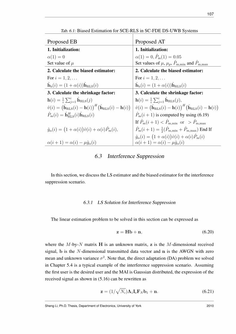
107
Tab. 6.1: Biased Estimation for SCE-RLS in SC-FDE DS-UWB Systems
Proposed EB Proposed AT1. Initialization: 1. Initialization:α(1) = 0 α(1) = 0, Pm(1) = 0.05
Set value of µ Set values of µ, µp, Pm,min and Pm,max
2. Calculate the biased estimator: 2. Calculate the biased estimator:For i = 1, 2, . . . For i = 1, 2, . . .
hb(i) = (1 + α(i))hRLS(i) hb(i) = (1 + α(i))hRLS(i)
3. Calculate the shrinkage factor: 3. Calculate the shrinkage factor:h(i) = 1
i
∑ij=1 hRLS(j) h(i) = 1
i
∑ij=1 hRLS(j),
v(i) =(hRLS(i)− h(i)
)H(hRLS(i)− h(i)
)v(i) =
(hRLS(i)− h(i)
)H(hRLS(i)− h(i)
)
Pm(i) = hHRLS(i)hRLS(i) Pm(i + 1) is computed by using (6.19)
If Pm(i + 1) < Pm,min or > Pm,max
gα(i) =(1 + α(i)
)v(i) + α(i)Pm(i), Pm(i + 1) = 1
2(Pm,min + Pm,max) End If
gα(i) =(1 + α(i)
)v(i) + α(i)Pm(i)
α(i + 1) = α(i)− µgα(i) α(i + 1) = α(i)− µgα(i)
6.3 Interference Suppression
In this section, we discuss the LS estimator and the biased estimator for the interferencesuppression scenario.
6.3.1 LS Solution for Interference Suppression
The linear estimation problem to be solved in this section can be expressed as
z = Hb + n, (6.20)
where the M -by-N matrix H is an unknown matrix, z is the M -dimensional receivedsignal, b is the N -dimensional transmitted data vector and n is the AWGN with zeromean and unknown variance σ2. Note that, the direct adaptation (DA) problem we solvedin Chapter 5.4 is a typical example of the interference suppression scenario. Assumingthe first user is the desired user and the MAI is Gaussian distributed, the expression of thereceived signal as shown in (5.16) can be rewritten as
z = (1/√
Nc)Λ1IeFNb1 + n. (6.21)
Sheng Li, Ph.D. Thesis, Department of Electronics, University of York 2010

108
Note that, if we consider the M -by-N matrix (1/√
Nc)Λ1IeFN as matrix H, then thissignal model has the same expression as (6.20).
Now, follow the expression as in equation (5.43), a linear equalizer w can be imple-mented to estimate the data vector as
b = Yw, (6.22)
where Y = FHN IH
e Z and Z = diag(z). The cost function for the development of the LSestimation is given by
JLS = ‖b−Yw‖2, (6.23)
and the LS design of the linear equalizer can be expressed as
wLS = (YHY)−1YHb = R−1LSpLS, (6.24)
where matrix RLS is defined as (YHY) and pLS represents the vector YHb.
Note that, the data vector can be expressed as
b = Ywo + εo, (6.25)
where wo is the optimal solution of the equalizer and εo is the measurement error. As-suming that εo has zero mean and covariance of σ2
eI, we can obtain
E[wLS] = wo, (6.26)
which indicates that the LS estimator of the equalizer is an unbiased estimator. Now, letus have a look at the following MSE:
E[‖wo − wLS‖2] = E[(wo − wLS)H(wo − wLS)] = var(wo, wLS). (6.27)
Defining vw = var(wo, wLS) and using the similar derivation in (6.7), we have
vw = tr{σ2e(Y
HY)−1}. (6.28)
In the interference suppression scenario, the unbiased LS estimator is obtained for theequalizer. It is possible to introduce the biased estimation to reduce the MSE between theoptimal equalizer wo and the LS estimator wLS. Note that, for the interference suppres-sion scenario, the typical objective is to minimize the overall performance which is deter-mined as the MSE of E[‖b− b‖2], rather than to minimize the MSE of E[‖wo − wLS‖2].
Sheng Li, Ph.D. Thesis, Department of Electronics, University of York 2010

109
Hence, different from the objective of biased estimator in parameter estimation scenario,the main motivation to introduce the bias in the interference suppression scenario is toprovide some initialization gain for the overall performance when the adaptive filteringtechniques are employed and the training data is limited. This can also help with trackingproblems and with robustness against interference.
6.3.2 Shrinkage Factor Estimation in Interference Suppression Schemes
The biased estimator of the equalizer with a shrinkage factor can be expressed as
wb = (1 + α)wLS, (6.29)
and the MSE of the biased estimator is given by
E[‖wo − wb‖2] = (1 + α)2vw + α2‖wo‖2. (6.30)
The objective of the biased estimation is to achieve a smaller MSE between wo and wLS,which can be expressed as
E[‖wo − wb‖2] ≤ E[‖wo − wLS‖2]. (6.31)
Substituting (6.30) and (6.28) into the left hand side and the right hand side of (6.10),respectively, and rearranging the terms, we have the objective equation
(1 + α)2vw + α2‖wo‖2 − vw ≤ 0. (6.32)
Note that the value of ‖wo‖2 is not given. We make the assumption that ‖wo‖2 ≤ Pw,where Pw is a positive real-valued constant. Hence, the problem to be solved becomes
f(α) = (1 + α)2vw + α2Pw − vw ≤ 0. (6.33)
The problem to be solved here has the similar expression as the problem solved in theprevious section 6.2.2. Using the similar derivation to obtain (6.14), the optimal solutionhere is given by
αopt =−vw
vw + Pw
. (6.34)
Sheng Li, Ph.D. Thesis, Department of Electronics, University of York 2010

110
It is necessary to examine the effect of the shrinkage factor to the overall MSE perfor-mance, which can be examined by calculating the MSE difference as follows:
E[‖b− bb‖2]− E[‖b− bLS‖2] = E[‖b− (1 + α)YwLS‖2]− E[‖b−YwLS‖2] (6.35)
Recalling the equation (6.24), we have
E[‖b−YwLS‖2] = ‖b‖2 − pHLSR
−1LSpLS,
andE[‖b− (1 + α)YwLS‖2] = ‖b‖2 +
(α2 − 1
)pH
LSR−1LSpLS.
Hence,E[‖b− bb‖2]− E[‖b− bLS‖2] = α2pH
LSR−1LSpLS ≥ 0. (6.36)
Although the biased equalizer will have a closer Euclidean distance to the optimalequalizer, equation (6.36) indicates that the shrinkage factor actually will increase theMSE between the data vector b and its estimator. Hence, in the interference suppressionscenario, the price to obtain a better presentation of the equalizer is the increased overallMSE performance. We remark that the biased estimators can be utilized here to acceleratethe convergence rate or they can bring an initial gain for the RLS adaptive algorithm thatis aiming at estimating the LS solution recursively.
In this section, the LS estimator of the equalizer is approached by the RLS adaptive al-gorithm that is detailed in Chapter 5.4.2. After calculating the wRLS(i) by using equation(5.54), the value of Pw and the variance of the LS estimator must be estimated. Usinga similar derivation as in subsection 6.2.2, the LMS-based update equation for α(i) ininterference suppression scenario is given by
α(i + 1) = α(i)− µ((
1 + α(i))vw(i) + α(i)Pw(i)
), (6.37)
where µ is the step size and the instantaneous estimator for the variance is given by
vw(i) =(wRLS(i)−wo(i)
)H(wRLS(i)−wo(i)
), (6.38)
where wo is replaced by the time averaged RLS equalizer estimator, that is wo(i) =1i
∑ij=1 wRLS(j).
In order to determine the values of Pw(i), the proposed EB and AT approaches areemployed. In the EB method, we set Pw(i) = wH
RLS(i)wRLS(i). In the AT approach, we
Sheng Li, Ph.D. Thesis, Department of Electronics, University of York 2010

111
Tab. 6.2: Biased Estimation for DA-RLS in SC-FDE DS-UWB Systems
Proposed EB Proposed AT1. Initialization: 1. Initialization:α(1) = 0 α(1) = 0, Pw(1) = 10
Set value of µ Set values of µ, µp, Pw,min and Pw,max
2. Calculate the biased estimator: 2. Calculate the biased estimator:For i = 1, 2, . . . For i = 1, 2, . . .
wb(i) = (1 + α(i))wRLS(i) wb(i) = (1 + α(i))wRLS(i)
bb(i) = Y(i)wb(i) bb(i) = Y(i)wb(i)
3. Calculate the shrinkage factor: 3. Calculate the shrinkage factor:wo(i) = 1
i
∑ij=1 wRLS(j) wo(i) = 1
i
∑ij=1 wRLS(j),
vw(i) is calculated by using (6.38) vw(i) is calculated by using (6.38)
Pw(i) = wHRLS(i)wRLS(i) Pw(i + 1) is computed by using (6.39)
If Pw(i + 1) < Pw,min or > Pw,max
gα(i) =(1 + α(i)
)v(i) + α(i)Pw(i), Pw(i + 1) = 1
2(Pw,min + Pw,max) End If
gα(i) =(1 + α(i)
)v(i) + α(i)Pw(i)
α(i + 1) = α(i)− µgα(i) α(i + 1) = α(i)− µgα(i)
employ the recursive equation
Pw(i + 1) = Pw(i) + µp
(2vw(i)
(vw(i) + vw(i)α(i) + α(i)Pw(i)
)(vw(i) + Pw(i)
)2 − α2(i)
), (6.39)
where µp is a small positive constant defined as the step size and similar to the algorithmin the parameter estimation scenario, we also set upper and lower limits for the valuesof Pw(i). For the implementation of the proposed shrinkage estimator, the DA problemdiscussed in Chapter 5.4.2 is considered. The RLS solution of the equalizer, which isrepresented as an M -dimensional vector wRLS(i), is obtained by using equation (5.54).In Table 6.2, the proposed biased estimators with two approaches to calculate Pw(i) aresummarized. Note that, the EB approach requires 4M + 3 complex multiplications and4M + 2 complex additions. For the AT method, in which Pm(i) is updated by usingequation (6.39), the number of complex multiplications required is 3M+9 and the numberof complex additions required is 3M + 8. Simulation results will demonstrate that in theinterference suppression scenario, both approaches will introduce initialization gain to theDA-RLS scheme. The AT method has faster convergence rate than the EB method, butEB method will introduce less MSE loss for the overall performance.
Sheng Li, Ph.D. Thesis, Department of Electronics, University of York 2010
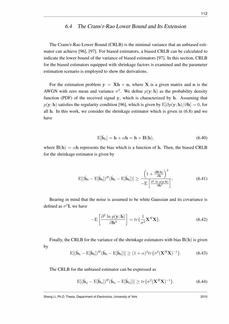
112
6.4 The Cramer-Rao Lower Bound and Its Extension
The Cramer-Rao Lower Bound (CRLB) is the minimal variance that an unbiased esti-mator can achieve [96], [97]. For biased estimators, a biased CRLB can be calculated toindicate the lower bound of the variance of biased estimators [97]. In this section, CRLBfor the biased estimators equipped with shrinkage factors is examined and the parameterestimation scenario is employed to show the derivations.
For the estimation problem y = Xh + n, where X is a given matrix and n is theAWGN with zero mean and variance σ2. We define p(y;h) as the probability densityfunction (PDF) of the received signal y, which is characterized by h. Assuming thatp(y;h) satisfies the regularity condition [96], which is given by E[∂p(y;h)/∂h] = 0, forall h. In this work, we consider the shrinkage estimator which is given in (6.8) and wehave
E[hb] = h + αh = h + B(h), (6.40)
where B(h) = αh represents the bias which is a function of h. Then, the biased CRLBfor the shrinkage estimator is given by
E[(hb − E[hb])H(hb − E[hb])] ≥
(1 + dB(h)
dh
)2
−E[
∂2 ln p(y;h)∂h2
] , (6.41)
Bearing in mind that the noise is assumed to be white Gaussian and its covariance isdefined as σ2I, we have
−E
[∂2 ln p(y;h)
∂h2
]= tr{ 1
σ2XHX}. (6.42)
Finally, the CRLB for the variance of the shrinkage estimators with bias B(h) is givenby
E[(hb − E[hb])H(hb − E[hb])] ≥ (1 + α)2tr{σ2(XHX)−1}. (6.43)
The CRLB for the unbiased estimator can be expressed as
E[(hu − E[hu])H(hu − E[hu])] ≥ tr{σ2(XHX)−1}. (6.44)
Sheng Li, Ph.D. Thesis, Department of Electronics, University of York 2010

113
It must be noted that the biased CRLB shown in (6.43) gives the minimum variancethat a shrinkage estimator can achieve and indicates that the shrinkage estimators attainthis lower bound. However, it is not as meaningful as the CRLB for the unbiased estimatorthat is shown in (6.44). The main reason is that for the unbiased estimator, the varianceis equal to the MSE of the estimator and hence the CRLB can also be considered asthe lower bound of the MSE performance. However, for the biased estimators, recallingthe equation (6.9), the MSE performance is determined not only by the variance of theestimator but also the bias, which is α2‖h‖2 in our case. In addition, there is an unknownvariable α in (6.43) and the derivation in this section so far is not able to give an optimalsolution of α that leads to minimum MSE. Hence, we extend the analysis here to obtain alower bound for the MSE performance of the biased estimators. The MSE of a shrinkagebiased estimator is given by
E[‖h− hb‖2] = var(h, hb)+bias(h, hb) = (1+α)2tr{σ2(XHX)−1}+α2‖h‖2. (6.45)
If we consider the MSE expression as a function of α, then the optimal solution of α
that corresponds to the minimum MSE can be obtained by computing the gradient withrespect to α and setting it to zero. The optimal α can be expressed as
αopt =−tr{σ2(XHX)−1}
tr{σ2(XHX)−1}+ ‖h‖2. (6.46)
Hence, the lower bound for the MSE performance of the shrinkage estimator is
E[‖h− hb‖2] ≥ (1 + αopt)2tr{σ2(XHX)−1}+ α2
opt‖h‖2
=tr{σ2(XHX)−1}‖h‖2
tr{σ2(XHX)−1}+ ‖h‖2
=1(
tr{σ2(XHX)−1}/‖h‖2)
+ 1tr{σ2(XHX)−1}.
(6.47)
The equation (6.47) is the extended CRLB for the shrinkage estimators and it indicatesthe followings:
1: The value of the scalar term 1(tr{σ2(XHX)−1}/‖h‖2)+1
is always smaller than 1 andlarger than 0, which means the lower bound of the shrinkage MSE is always lower thanthe CRLB for the unbiased estimators that is given in (6.44).
2: The distance between the bounds of unbiased estimators (in (6.44)) and the ex-tended CRLB for shrinkage estimators (in (6.47)) is dependent on the noise variance σ2.Interestingly, in the low SNR scenarios where σ2 is large, the distance between the bounds
Sheng Li, Ph.D. Thesis, Department of Electronics, University of York 2010

114
becomes larger than in the high SNR scenarios. Actually, if the SNR is high and σ2 → 0,then these two bounds tend to be the same. The simulation results will also demonstratethis phenomenon as the gain of the shrinkage estimator over the unbiased LS solution isincreasing as the SNR reduces.
3: If the white Gaussian is assumed and the shrinkage estimator is obtained based on aminimum variance unbiased estimator (MVUE), then the optimal α is given in (6.46) andthe lower bound shown in (6.47) is achieved.
6.5 Simulations
100 200 300 400 500 600 700 800 900 100010
−2
10−1
100
101
102
Number of Blocks
MS
E
SNR=0dB, 1User
RLSProposed EBProposed ATUnbiased CRLBBiased extended CRLB
Fig. 6.1: MSE performance (‖h − h‖2) of the biased structured channel estimation (SCE). Theparameters used: RLS (λ = 0.998, δ = 10). Proposed EB: µ = 0.075 and proposed AT:µ = 0.075, µp = 0.05, Pm,min = 0.05, Pm,max = 0.15.
In this section, the biased estimators are employed in the SCE and DA detectors that aredeveloped in Chapter 5 and their MSE performance are compared with the conventionalSCE-RLS and DA-RLS algorithms, respectively. The simulation environment is set to
Sheng Li, Ph.D. Thesis, Department of Electronics, University of York 2010

115
−10 −5 0 5 10 1510
−3
10−2
10−1
100
101
SNR (dB)
MS
E
3users
RLSProposed EBProposed AT
Fig. 6.2: MSE performance (‖h− h‖2) of the biased SCE with different SNRs.
the same as in Chapter 5. The pulse shape adopted is the RRC pulse with the pulse-width Tc = 0.375ns. The length of the data block is set to N = 32 symbols. TheWalsh spreading code with a spreading gain Nc = 8 is generated for the simulationsand we assume that the maximum number of active users is 7. The channel has beensimulated according to the standard IEEE 802.15.4a channel model for the NLOS indoorenvironment as shown in [23]. We assume that the channel is constant during the wholetransmission and the time domain CIR has 100 taps. The sampling rate of the standardchannel model is 8GHz. The CP guard interval has the length of 35 chips, which hasthe equivalent length of 105 samples and it is enough to eliminate the IBI. The uncodeddata rate of the communication is approximately 293Mbps. For all the simulations, theadaptive filters are initialized as null vectors. All the curves are obtained by averaging200 independent simulations.
In the first experiment, we examine the proposed biased estimators for the SCE in asingle user system with 0dB SNR. In Fig. 6.1, the MSE performance of the channel esti-mators are compared as a function of number of blocks transmitted. The RLS algorithmapproaches the unbiased CRLB given in (6.44) while the proposed biased estimators ap-
Sheng Li, Ph.D. Thesis, Department of Electronics, University of York 2010

116
1 2 3 4 5 6 710
−2
10−1
100
Number of Users
MS
E
SNR=0dB
RLSProposed EBProposed AT
Fig. 6.3: MSE performance (‖h− h‖2) of the biased SCE with different number of users.
proach the extended CRLB as given in (6.47). The proposed estimators converge fasterthan the RLS algorithm and the stead-state performance is also improved. The proposedAT algorithm in this scenario performs the best. Note that the additional complexity toemploy the biased estimation techniques increases linearly with the length of the channel.
Fig. 6.2 illustrates the MSE performance of different channel estimators in a scenariowith 3 users and different SNRs. The parameters for the adaptive algorithms are the sameas those used to obtain Fig. 6.1 and 200 training blocks are transmitted for each run. Forall the simulated SNRs, the proposed biased algorithms outperform the RLS algorithm.In low SNR scenarios, the gain achieved by the biased estimator is larger than in the highSNR scenarios.
Fig. 6.3 shows the MSE performance of different channel estimators in a 0dB scenario,with different numbers of active users. The parameters for the adaptive algorithms are thesame as those used to obtain Fig. 6.1 and 200 training blocks are transmitted for each run.The proposed biased algorithms outperform RLS algorithm in all the scenarios.
Sheng Li, Ph.D. Thesis, Department of Electronics, University of York 2010

117
20 40 60 80 100 120 140 160 180 200
100
Number of blocks
MS
E
SNR=3dB, 3Users
RLS
Proposed EB
Proposed AT
MMSE
Fig. 6.4: MSE performance (‖b− b‖2) of the biased estimator in DA-RLS scheme with 3users in3dB SNR. The parameters used: RLS (λ = 0.998, δ = 2). Proposed EB: µ = 0.0075and proposed AT: µ = 0.0075, µp = 0.005, Pm,min = 10, Pm,max = 20.
In Fig. 6.4, the MSE performance of the estimators in the DA scheme are compared asa function of number of blocks transmitted. There is an initial gain achieved by the biasedestimators and the proposed AT algorithm performs best with 200 transmitted trainingblocks. Note that the MSE performance compared here is the overall MSE performancethat is given by ‖b − b‖2. As discussed in Chapter 6.3.2, although the biased equalizerwill have a closer Euclidean distance to the optimal equalizer, equation (6.36) indicatesthat the shrinkage factor actually will increase the overall MSE between the data vector b
and its estimator. Hence, in the DA scheme, the main idea to employ the biased estimatorsis to achieve an initial gain for the RLS adaptive algorithm.
In Fig. 6.5, we examine the MSE performance of the estimators in the DA scheme ina short data support scenario. For a 3-user communications with 3 dB SNR, the numberof training blocks is set to 50. The parameters for the adaptive algorithms are the sameas those used to obtain Fig. 6.4. After the training stage, all the adaptive algorithms areoperated in steady-state stage. In this experiment, we show that the biased estimators inthe interference suppression scenario (DA scheme as an example) can be employed in the
Sheng Li, Ph.D. Thesis, Department of Electronics, University of York 2010

118
20 40 60 80 100 120 140 160 180 200
100
Number of blocks
MS
E
3dB, 3Users
MMSE
RLS
Proposed EB
Proposed AT
Fig. 6.5: MSE performance (‖b − b‖2) of the biased estimator in short data support DA-RLSscheme with 3users in a scenario with SNR=3dB.
systems with short training sequence and the initial gain can be maintained.
In Fig. 6.6, we examine the MSE performance of the estimators in the DA schemein a 10dB SNR scenario. The proposed estimators still have an initial gain over the con-ventional RLS algorithm. In this scenario, the overall MSE performance loss introducedby the proposed AT algorithm can be spotted after around 40 blocks transmitted. How-ever, for the EB algorithm, the performance is still better than the RLS with 200 trainingblocks.
In Fig. 6.7, we examine the uncoded BER performance of the biased estimators in theSCE scheme in a system with 3 users in different SNRs. In this experiment, the parametersfor the adaptive algorithms are the same as those used to obtain Fig. 6.1 and only 50training blocks are transmitted for each run. The proposed biased estimators achieve aBER gain around 1dB at the low SNR scenarios. The proposed AT scheme outperformsthe EB and conventional RLS algorithm in the tested scenarios. As the SNR increases,the difference between the BER performance of these algorithms become smaller. Forthe DA scheme, the similar performance gain can be obtained for the proposed biased
Sheng Li, Ph.D. Thesis, Department of Electronics, University of York 2010

119
20 40 60 80 100 120 140 160 180 200
10−0.2
10−0.1
100
100.1
Number of blocks
MS
E
SNR=10dB, 3Users
RLS
Proposed AT
MMSE
Proposed EB
Fig. 6.6: MSE performance (‖b− b‖2) of the biased estimator in DA-RLS scheme with 3users ina scenario with SNR=10dB.
estimators and the results is not included in the figure for the sake of clarity.
6.6 Conclusion
In this Chapter, shrinkage biased estimators are developed in the scenarios of parame-ter estimation and interference suppression. LMS-based adaptive algorithms are devisedto obtain the shrinkage factors. The biased CRLB has been computed and we have ex-tended it to obtain a lower bound for the MSE performance of the shrinkage biased esti-mators. The incorporation of the proposed estimators has been considered in the detectionschemes of SCE and DA as introduced in Chapter 5. The simulation results demonstratethe improved MSE performance of the biased estimators in different scenarios.
Sheng Li, Ph.D. Thesis, Department of Electronics, University of York 2010

120
−2 0 2 4 6 8 10 12 14 1610
−2
10−1
100
SNR (dB)
BE
R
3 Users
RLSProposed EBProposed AT
Fig. 6.7: BER performance in SCE scheme with different SNRs in a 3 user scenario.
Sheng Li, Ph.D. Thesis, Department of Electronics, University of York 2010

7. CONCLUSIONS AND FUTURE WORK
Contents7.1 Summary of Work . . . . . . . . . . . . . . . . . . . . . . . . . . . . 121
7.2 Future Work . . . . . . . . . . . . . . . . . . . . . . . . . . . . . . . 123
7.1 Summary of Work
In this thesis, we have investigated interference suppression adaptive algorithms for themultiuser DS-UWB systems. These algorithms are implemented in the time domain insymbol by symbol transmission systems and in the frequency domain in block by blocktransmission systems. Reduced-rank adaptive algorithms are proposed for the time do-main interference suppression tasks, a novel generic reduced-rank receiver and SAABFscheme are proposed with LMS and RLS adaptive algorithms that are developed based onthe MMSE criterion (Chapter 3), blind reduced-rank receivers are proposed based on theCCM criterion and NSG and RLS versions are developed (Chapter 4). The LMS, RLS andCG-based adaptive detectors are developed for SC-FDE in DS-UWB systems (Chapter 5)and shrinkage estimators are proposed to improve the performance of the RLS versionsof the frequency domain detectors (Chapter 6). The proposed reduced-rank receivers canbe employed in spread-spectrum systems which encounter large filter problems and sufferfrom severe interferences. The adaptive algorithms that is developed in SC-FDE systemscan also be used in OFDM systems.
In Chapter 3, firstly, a generic reduced-rank scheme that jointly updates the projectionvector and the reduced-rank filter is proposed. We pointed out that although this genericscheme outperforms the existing reduced-rank schemes in the multiuser DS-UWB sys-tems, it still has high computational complexity. Hence, a novel reduced-rank interfer-ence suppression scheme is investigated and named SAABF, in which the design of theprojection vector in the generic scheme is constrained with a multi-branch structure andthe significant complexity reduction is achieved. Simulation results demonstrate that theperformance of the generic scheme is maintained in the SAABF scheme. Then, LMS and

122
RLS algorithms were developed for adaptive implementation of the SAABF scheme. Adiscussion of the global optimality of the reduced-rank filter was presented, and the re-lationships between the SAABF and the generic scheme and the full-rank scheme wereestablished. We remark that the proposed SAABF scheme is a promising low-complexitysolution for the communication systems that encounter large filter problems and severeinterferences.
In Chapter 4, blind reduced-rank adaptive receivers based on the JIO and CCM crite-rion are proposed for the multiuser DS-UWB systems. The NSG and RLS adaptive al-gorithms are developed for the proposed blind receiver. In the RLS version, the columnsof the projection matrix are updated one by one. We found that the performance of theblind reduced-rank scheme can be improved by calculating the columns of the projectionmatrix individually. This is because the columns of the projection matrix can be consid-ered as the direction vectors on the dimensions of the subspace and a better representationof the projection procedure can be obtained via using the column-by-column adaptation.However, the computational complexity will be increased by using the column-by-columnadaptation. In order to reduce the complexity, an approximation is devised for the RLSversion. The robustness of the proposed receivers has been demonstrated in the scenariothat the blind receivers are required to suppress the ISI, MAI and NBI together. Comparedto the SAABF scheme proposed in Chapter 3, the proposed blind reduced-rank receiversoffer higher spectrum efficiency while only requiring the time synchronization and thespreading code of the desired user.
In Chapter 5, two adaptive detection schemes are proposed based on the MMSE lin-ear detection strategy for SC-FDE in DS-UWB systems, which are termed SCE and DA.Cyclic prefix is employed in both schemes. LMS, RLS and CG adaptive algorithms aredeveloped for the adaptive implementations. For the SCE scheme, the channel estimationis carried out in the frequency domain and the estimated channel coefficients are thensubstituted into the expression of the MMSE detector. It should be noted that the noisevariance and the number of users are required in the expression of the MMSE detec-tor. For this purpose, we estimate the noise variance via the maximum likelihood (ML)method and develop a low-complexity algorithm to estimate the number of active users.For the DA scheme, only one filter is implemented in the frequency domain to suppressthe interference. A new signal model is employed in the DA scheme and is extended tothe adaptive implementations that enables a simplified linear adaptive filter design. Simu-lation results illustrate that the SCE scheme outperforms the DA scheme in the multiuserDS-UWB systems, while the DA scheme has a simpler receiver structure and lower com-plexity.
Sheng Li, Ph.D. Thesis, Department of Electronics, University of York 2010

123
In Chapter 6, biased adaptive estimation techniques based on shrinkage estimators aredevised and incorporated into RLS versions of the SCE and DA schemes that are pro-posed in Chapter 5. LMS-based adaptive algorithms are proposed to recursively computethe shrinkage factors. For the SCE scheme, the biased estimator achieves a lower MSEof the channel estimation than the SCE-RLS. For the DA scheme, the biased estimatoris developed to reduce the MSE of the estimated equalizer. Note that to equip these bi-ased estimators, the additional complexity required increases linearly with the length ofthe estimated parameter vector. In this chapter, the biased CRLB that constitutes a fun-damental estimation limit of the shrinkage estimators is computed and we extend it to alower bound for the MSE performance of the shrinkage estimators. Simulations are car-ried out in multiuser DS-UWB systems and the performance improvements are achievedin low SNR scenarios and with short data support. The biased estimators obtained in thiswork are developed in general expressions for the scenarios of parameter estimation andinterference suppression. Hence, they can be implemented into other communication sys-tems to improve the performance of the unbiased LS solutions, especially for the systemsthat operate in low SNR and with short data support.
7.2 Future Work
Some suggestions for future work based on this thesis are given below.
In Chapter 3, novel reduced-rank algorithms are proposed based on the JIO and switch-ing. One possible future implementation scenario of the proposed schemes is the cooper-ative UWB communication systems. In a cooperative transmission system, data is trans-mitted or relayed from the terminals or users to the destination user or terminal. The mainreason to employ the cooperative communication is to transmit information through anoptimally selected or combined route from all the possibilities such that the communi-cation resources can be fully utilized and systems can perform with increased reliability,lower transmit power, larger coverage and higher transmission rate [98]- [101]. For DS-UWB systems, cooperative communications have the potential to increase the coverageand the data rate while requiring low transmitted power. In Chapter 3, the proposedSAABF scheme is a promising technique to the cooperative communications because ofits low-complexity and remarkable interference suppression ability. Another possible im-plementation of the SAABF scheme is to modify it to achieve timing acquisition. For theUWB systems, accurate timing acquisition is required and the performance may loss dra-matically if the timing errors larger than a small fraction of nanosecond [102]. In [103], anear-far-resistant demodulator with symbol-level timing acquisition scheme is proposed
Sheng Li, Ph.D. Thesis, Department of Electronics, University of York 2010

124
based on MMSE criterion for CDMA systems in AWGN channel. We can modify theSAABF scheme to solve the MMSE synchronization problem as modeled in [103] forDS-UWB systems.
In Chapter 4, blind reduced-rank algorithms are proposed for DS-UWB systems basedon CCM and JIO criterion. The BER performance can be improved by including cod-ing techniques such as turbo and low-density parity-check (LDPC) coding. An iterative(turbo) equalizer has been proposed for MSWF-based reduced-rank scheme in [104], inwhich the performance of the coded reduced-rank scheme is significantly better than theuncoded schemes. We can also employ channel coding into the blind reduced-rank al-gorithms in the future work. Since the performance of the proposed JIO-CCM schemesoutperforms the MSWF algorithms in the uncoded systems, a large coding gain can beexpected from the proposed scheme.
In Chapter 5, the adaptive frequency domain detection schemes have been proposedfor SC-FDE in DS-UWB systems. In fact, the signal model employed and the adaptivealgorithms developed in this chapter can be modified to operate in OFDM-based block byblock transmission systems. In Chapter 6, biased estimators are proposed to improve theperformance of the RLS versions of the frequency domain equalizers that are introducedin Chapter 5. A further development of the biased estimation can be achieved by intro-ducing a matrix-form shrinkage factor. For example, the biased estimator in parameterestimation scenario proposed in Chapter 6 is given by hb = (1 + α)hu, where a scalarshrinkage factor is employed for all the parameters in the L-dimensional vector hu. Fora further development, the biased estimator can be expressed as hb = (I + M)hu, whereM is a diagonal matrix and its diagonal vector is m = [α1, α2, . . . , αL]. This method willallow a better way to assign the bias for each parameter in the vector hu.
Sheng Li, Ph.D. Thesis, Department of Electronics, University of York 2010

APPENDIX

A. PROOF OF THE EQUIVALENCE OF THE SCHEMES
In this section, we prove that the SAABF (1,D,M) is equivalent to the the genericscheme and the SAABF (1,1,M) is equivalent to the full-rank scheme.
Firstly, we express the MMSE solutions for the SAABF scheme as
wMMSE = R−1p, ψMMSE = R−1ψ pψ (A.1)
where R = E[Rin(i)P(i)ψ(i)ψH(i)PH(i)RHin(i)], p = E[d∗(i)Rin(i)P(i)ψ(i)], Rψ =
E[PH(i)RHin(i)w(i + 1)wH(i + 1)Rin(i)P(i)] and pψ = E[d(i)PH(i)RH
in(i)w(i + 1)].Revisit the expression of the basis functions in the SAABF scheme in (3.12). In SAABF(1,D,M), the length of the inner function equals to the length of the basis function and theposition matrix in (3.13) becomes an MD-by-MD identity matrix. Hence, the MMSEsolutions of the generic scheme shown in (3.10) are the same as (A.1) when P(i) is anidentity matrix, which means the SAABF (1,D,M) is equivalent to the generic scheme.
Secondly, we prove that the SAABF (1,1,M), or the generic scheme with D=1, isequivalent to the full-rank scheme in the sense that they have the same MMSE corre-sponding to the optimum solutions. Here, we expand the cost function of the genericscheme that is shown in (3.9)
JG = σ2d − E[d(i)tH(i)RH
in(i)w(i)]− E[d∗(i)wH(i)Rin(i)t(i)]
+ E[wH(i)Rin(i)t(i)tH(i)RH
in(i)w(i)].(A.2)
In the case of D=1, the input data matrix Rin(i)=rT (i) becomes a 1-by-M vector, thereduced-rank filter has only one tap and hence the wopt is a scalar term and we can findthe relationship between topt and wopt as
topt = (E[r∗(i)rT (i)]woptw∗opt)
−1E[d(i)r∗(i)]wopt = (RT )−1p∗(w∗opt)
−1

Appendix 127
Hence, the second term in (A.2) becomes
E[d(i)tH(i)RHin(i)w(i)] = tH
optE[d(i)r∗(i)]wopt = [(RT )−1p∗(w∗opt)
−1]Hp∗wopt
= pT (RT )−1p∗ = (pHR−1p)T = pHR−1p.(A.3)
Note that here we use the fact that the transpose of the scale term pHR−1p is itself and(RT )H = RT . Since the third scalar term in (A.2) is the conjugate of the second term, wehave E[d∗(i)wH(i)Rin(i)t(i)] = (pHR−1p)H = pHR−1p. The fourth term of (A.2) canbe expanded as
E[wH(i)Rin(i)t(i)tH(i)RH
in(i)w(i)] = w∗optE[rT (i)toptt
Hoptr
∗(i)]wopt
= w∗optE[tH
optr∗(i)rT (i)topt]wopt = pT (RT )−1p∗ = pHR−1p.
(A.4)
Hence, the MMSE of the generic scheme for D=1 is JGMMSE = σ2d − pHR−1p, which
is the same as the MMSE obtained via the full-rank Wiener filter as shown in (3.4). Thiscompletes the proof.
Sheng Li, Ph.D. Thesis, Department of Electronics, University of York 2010

B. ANALYSIS OF THE OPTIMIZATION PROBLEM
In this Appendix, we discuss the optimization problem of the proposed SAABFscheme. Specially, we consider the convergence of the SAABF scheme via the com-putation of the Hessian matrix of the MSE cost function which can be expressed as
JMSE(w(i), ψ(i)) = E[|d(i)− wH(i)Rin(i)P(i)ψ(i)|2]. (B.1)
It is known that the convexity of the function can be verified if its Hessian matrix is pos-itive semi-definite. However, the SAABF scheme includes a discrete optimization of theposition matrix and a continuous adaptation of the reduced-rank filter and the projectionvector. For the position matrix selection problem, we constrain the design of the posi-tion matrix to a small number of pre-stored matrices and switch between these matricesto choose the instantaneous sub-optimum position matrix. This feature of the SAABFscheme suggests that the optimum values of the three variables of the MSE cost functionmay be difficult to obtain together, and that there are multiple solutions of the cost func-tion. The convexity is only verified when we consider one of the continuously adaptedvariables whilst the others are kept fixed. Firstly, let us compute the D-by-D Hessianmatrix for (B.1) with respect to the reduced-rank filter:
HJ,w =∂2JMSE
∂wH(i)∂w(i)= E[Rin(i)P(i)ψ(i)ψH(i)PH(i)RH
in(i)]. (B.2)
For any D-dimensional non-zero vector a, we discuss the following scale term
aHHJ,wa = E[aHRin(i)P(i)ψ(i)ψH(i)PH(i)RHin(i)a] = E[a(i)a∗(i)] = E[|a(i)|2],
(B.3)where a(i) = aHRin(i)P(i)ψ(i). Assume that the position matrix P(i) and the projectionvector ψ(i) are fixed. The scale term in (B.3) is always nonnegative. Hence, the Hessianmatrix HJ,w is a positive semi-definite matrix. Similarly, the qD-by-qD Hessian matrixfor (B.1) with respect to the projection vector is
HJ,ψ = E[PH(i)RH
in(i)w(i)wH(i)Rin(i)P(i)], (B.4)

Appendix 129
which is also a positive semi-definite matrix if the position matrix and the reduced-rankfilter are fixed.
In the SAABF scheme, after determined the position matrix, the optimization prob-lems for the projection vector and the reduced-rank filter can be consider as a bi-convexproblem [78]: by fixing one of the parameters, the other design problem is convex. In or-der to test the convergence of the SAABF scheme in the case of jointly updating w(i) andψ(i), we checked the impact of different initializations, which confirmed that the perfor-mance of the algorithms are not subject to degradation due to the initialization. However,the proof of the global optimum and no local minima with the joint adaptive algorithmremains an interesting open problem to be researched.
Sheng Li, Ph.D. Thesis, Department of Electronics, University of York 2010

C. CONVERGENCE PROPERTIES FOR THE CCM FUNCTION
In this section, we examine the convergence properties of the cost function JJIO =12E
[(|y(i)|2 − 1)2
], where y(i) = wH(i)TH(i)r(i). For simplicity of the following anal-
ysis, we drop the time index (i). The received signal is given by
r =K∑
k=1
√EkPrSe,khkbk + η + n,
=K∑
k=1
√Ekbkpk + η + n = PkAkb + η + n,
(C.1)
where pk = PrSe,khk, k = 1, . . . , K, are the signature vectors of the users. Pk =
[p1, . . . ,pK ], Ak = diag(√
E1, . . . ,√
EK) and b = [b1, . . . , bK ]. η and n representthe ISI and AWGN, respectively. We assume that bk, k = 1, . . . , K, are statisticallyindependent i.i.d random variables with zero mean and unit variance and are independentto the noises. Firstly, we will discuss the noise-free scenario for the analysis, in which,the output signal of the JIO receiver is given by
y = wHTHPkAkb = εHb, (C.2)
where ε , AHk PH
k Tw = [ε1, . . . , εK ]. Assuming that user 1 is the desired user andrecalling the constraint wHTHp1 = �, where � is a real-valued constant. We obtain thatthe first element of the vector ε can be expressed as
ε1 =√
E1pH1 Tw =
√E1�. (C.3)
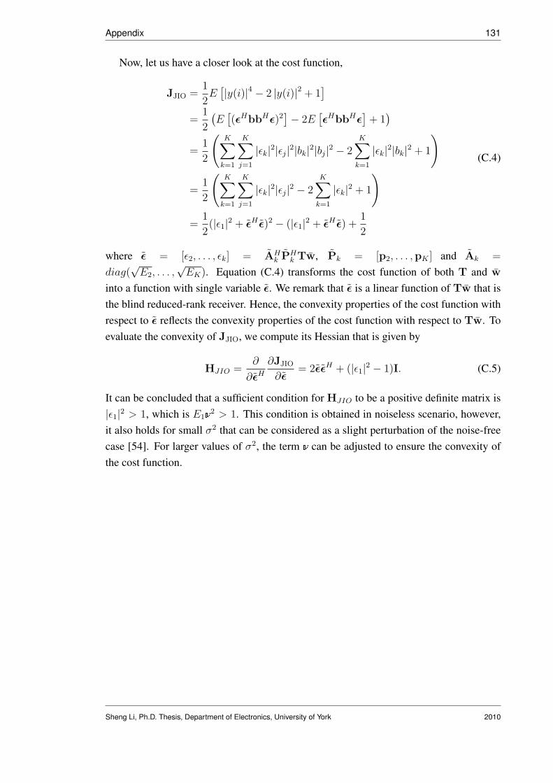
Appendix 131
Now, let us have a closer look at the cost function,
JJIO =1
2E
[|y(i)|4 − 2 |y(i)|2 + 1]
=1
2
(E
[(εHbbHε)2
]− 2E[εHbbHε
]+ 1
)
=1
2
(K∑
k=1
K∑j=1
|εk|2|εj|2|bk|2|bj|2 − 2K∑
k=1
|εk|2|bk|2 + 1
)
=1
2
(K∑
k=1
K∑j=1
|εk|2|εj|2 − 2K∑
k=1
|εk|2 + 1
)
=1
2(|ε1|2 + εH ε)2 − (|ε1|2 + εH ε) +
1
2
(C.4)
where ε = [ε2, . . . , εk] = AHk PH
k Tw, Pk = [p2, . . . ,pK ] and Ak =
diag(√
E2, . . . ,√
EK). Equation (C.4) transforms the cost function of both T and w
into a function with single variable ε. We remark that ε is a linear function of Tw that isthe blind reduced-rank receiver. Hence, the convexity properties of the cost function withrespect to ε reflects the convexity properties of the cost function with respect to Tw. Toevaluate the convexity of JJIO, we compute its Hessian that is given by
HJIO =∂
∂εH
∂JJIO
∂ε= 2εεH + (|ε1|2 − 1)I. (C.5)
It can be concluded that a sufficient condition for HJIO to be a positive definite matrix is|ε1|2 > 1, which is E1�2 > 1. This condition is obtained in noiseless scenario, however,it also holds for small σ2 that can be considered as a slight perturbation of the noise-freecase [54]. For larger values of σ2, the term � can be adjusted to ensure the convexity ofthe cost function.
Sheng Li, Ph.D. Thesis, Department of Electronics, University of York 2010

BIBLIOGRAPHY
[1] R. A. Scholtz, “Multiple access with time-hopping impulse modulation,” Proc. IEEEMILCOM, pp. 447-450, 1993.
[2] M. Z. Win and R. A. Scholtz, “Impulse radio: how it works,” IEEE CommunicationsLetters, vol. 2, no. 2, pp. 36-38, Feb. 1998.
[3] M. Z. Win and R. A. Scholtz, “Ultra-wide bandwidth time-hopping spread-spectrumimpulse radio for wireless multiple-acess communications,” IEEE Trans. Communi-cations, vol. 48, no. 4, pp. 679-689, Apr. 2000.
[4] First report and order FCC-02048, Federal Communications Commission, 2002.
[5] R. C. Qiu, “A Study of the Ultra-Wideband Wireless Propagation Channel and Opti-mum UWB Receiver Design,” IEEE Journal on Selected Areas in Communications,vol. 20, no. 9, pp. 1628-1637, Dec. 2002.
[6] I. Oppermann et al., UWB Theory and Applications, John Wiley, 2004.
[7] K. Siwiak and D. McKeown, Ultra-wideband Radio Technology, Wiley, Apr. 2004.
[8] F. Nekoogar, Ultra Wideband Communications: Fundamentals and Application,Prentice Hall, Dec. 2004.
[9] D. Tse and P. Viswanath, Fundamentals of Wireless Communication, Cambridge Uni-versity Press, 2005.
[10] M. Ghavami, L. B. Michael and R. Kohno, Ultra Wideband Signals and Systems inCommunication Engineering, John Wiley, 2004.
[11] D. Cassioli, M. Z. Win et al., “Low Complexity Rake Receivers in Ultra-WidebandChannels,” IEEE Trans. Wireless Communications, vol. 6, no. 4, pp. 1265-1275, Apr.2007.
[12] R. Fisher, R. Kohno et al., “DS-UWB Physical Layer Submission to IEEE 802.15Task Group 3a (Doc. Number P802.15-04/0137r4),” IEEE P802.15, Jan. 2005.
[13] B. Parr, B. Cho, K. Wallace and Z. Ding, “A novel ultra-wideband pulse designalgorithm,” IEEE Communications Letters, vol. 7, no. 5, pp. 219-221, May. 2003.

Bibliography 133
[14] X. Wu, Z. Tian, T. N. Davidson and G. B. Giannakis, “Optimal Waveform Designfor UWB Radios,” IEEE International Conference on Acoustics, Speech, and SignalProcessing, 2004. Proceedings.
[15] M. Z. Win, D. Dardari, A. F. Molish et al., “History and Applications of UWB,”Proceedings of the IEEE, vol. 97, no. 2, pp 198-204, Feb. 2009.
[16] B. Mielczarek, M. Wessman and A. Svensson, “Performance of Coherent UWBRake Receivers using different Channel Estimators,” IEEE Vehicular TechnologyConference, vol. 3, pp. 1880-1884, Oct. 2003.
[17] A. Parihar, L. Lampe, R. Schober, and C. Leung, “Equalization for DS-UWBsystems–Patr I: BPSK modulation,” IEEE Trans. Communications, vol. 55, no. 6 pp.1164-1173, Jun. 2007.
[18] M. Hamalainen, R. Tesi, J. Iinatti and V. Hovinen, “On the Performance Comparisonof Different UWB Data Modulation Schemes in AWGN Channel in the Presence ofJamming,” IEEE Radio and Wireless Conference, 2001.
[19] I. Guvenc and H. Arslan, “On the modulation options for UWB systems,” IEEEMilitary Communications Conference (MILCOM), vol. 2, pp. 892¨C897, Oct. 2003.
[20] D. Cassioli, M. Z. Win, and A. F. Molisch, “A statistical model for the UWB indoorchannel,” Proc. 53rd IEEE Vehicular Technology Conference, vol. 2, pp. 1159¨C1163,May. 2001.
[21] D. Cassioli, M. Z. Win and A. F. Molisch, “The Ultra-Wide Bandwidth Indoor Chan-nel: From Statistical Model to Simulations,” IEEE Journal on Selected Areas in Com-munications, vol. 20, no. 6, pp 1247-1257, Aug. 2002.
[22] J. Foerster et al., “ChannelModeling Subcommittee Final Report,” IEEE, DocumentIEEE 02490r0P802-15 SG3a, 2003.
[23] A. F. Molisch et al., “IEEE 802.15.4a Channel Model - Final Report,” Tech. Rep.Doc. IEEE 802.15-0400662-02-004a, 2005.
[24] A. F. Molisch, “Ultrawideband Propagation Channels-Theory, Measurement, andModeling,” IEEE Trans. Vehicular Technology, vol. 54, no. 5, Sep. 2005.
[25] A. F. Molisch et al., “A Comprehensive Standardized Model for UltrawidebandPropagation Channels,” IEEE Trans. Antennas and Propagation, vol. 54, no. 11, pp.3151-3166, Nov. 2006.
[26] S. Haykin, Adaptive Filter Theory,Fourth Edition, Pearson Education, 2002.
Sheng Li, Ph.D. Thesis, Department of Electronics, University of York 2010
Bibliography 134
[27] D. P. O’Leary, “The Block conjugate gradient algorithms and Related Methods,”Linear Algebra and its Applications, vol. 29, pp. 293-322, 1980.
[28] J. S. Lim and C. K. Un, “Block conjugate gradient algorithms for adaptive filtering,”Signal Processing, vol. 55, pp. 65-77, Nov. 1996.
[29] P. Chang and A. N. Willson,Jr., “Analysis of Conjugate Gradient Algorithms forAdaptive Filtering,” IEEE Trans. Signal Processing, vol. 48, no. 2, pp. 409-418, Feb.2000.
[30] H. Ge, L. L. Scharf and M. Lundberg, “Reduced-Rank Multiuser Detectors Basedon Vector and Matrix Conjugate Gradient Wiener Filters,” IEEE 5th Workshop onSignal Processing in Wireless Communications, pp. 189-193, 2004.
[31] A. S. Lalos and K. Berberidis, “An efficient conjugate gradient method in the fre-quency domain: Application to channel equalization,” Signal Processing, vol. 88, pp.99-116, Jan. 2008.
[32] S. Gezici, C. Mung, H. V. Poor and H. Kobayashi, “A genetic algorithm based fingerselection scheme for UWB MMSE rake receivers,” IEEE International Conf. on UWB(ICUWB), pp. 164-169, Sept. 2005.
[33] J. Zhang, T. D. Abhayapala and R. A. Kennedy, “Principal components trackingalgorithms for synchronization and channel identification in UWB systems,” IEEEEighth International Symposium on Spread Spectrum Techniques and Applications(ISSSTA), pp. 369-373, Sept. 2004.
[34] S. H. Wu et al., “Multistage MMSE receivers for ultra-wide bandwidth impulseradio communications,” International Workshop on Ultra Wideband Systems, Jointwith Conference on Ultrawideband Systems and Technologies. pp. 16-20, May. 2004.
[35] Z. Tian, H. Ge and L. L. Scharf, “Low-complexity multiuser detection and reduced-rank Wiener filters for ultra-wideband multiple access,” IEEE International Confer-ence on Acoustics, Speech, and Signal Processing (ICASSP), vol. 3, pp. 621-624,Mar. 2005.
[36] Y. Tian and C. Yang, “Reduced-order Multiuser Detection in Multi-rate DS-UWB Communications,” IEEE International Conference on Communications (ICC),vol.10, pp. 4746-4750, Jun. 2006.
[37] Q. Z. Ahmed and L. L. Yang, “Reduced-Rank Adaptive Multiuser Detection in Hy-brid Direct-Sequence Time-Hopping Ultrawide Bandwidth Systems,” IEEE Trans.Wireless Communications, vol. 9, no. 1, pp. 156-167, Jan. 2010.
Sheng Li, Ph.D. Thesis, Department of Electronics, University of York 2010

Bibliography 135
[38] G. Kutz and D. Raphaeli, “Determination of Tap Positions for Sparse Equalizers,”IEEE Trans. Communications, vol.55, no. 9, pp. 1712-1724, Sept. 2007.
[39] S. Burykh and K. Abed-Meraim, “Reduced-rank adaptive filtering using Krylov sub-space,” EURASIP Journal on Applied Signal Processing, vol. 12, pp. 1387-1400,2002.
[40] A. M. Haimovich and Y. Bar-Ness, “An eigenanalysis interference canceler,” IEEETrans. Signal Processing, vol. 39, no. 1, pp. 76-84, Jan. 1991.
[41] J. S. Goldstein and I. S. Reed, “Reduced-rank adaptive filtering,” IEEE Trans. SignalProcessing, vol. 45, no. 2, pp. 492-496, Feb. 1997.
[42] M. L. Honig and J. S. Goldstein, “Adaptive reduced-rank interference suppressionbased on the multistage wiener filter,” IEEE Trans. Communications, vol. 50, no. 6,pp. 986-994, Jun. 2002.
[43] J. D. Hiemstra, Robust Implementations of the Multistage Wiener Filter, PhD. thesisof Virginia Polytechnic Institute and State University, Apr. 2003.
[44] J. S. Goldstein,I. S. Reed, and L. L. Scharf, “A multistage representation of theWiener filter based on orthogonal projections,” IEEE Trans. Information Theory, vol.44, no. 11, pp. 2943-2959, Nov. 1998.
[45] M. L. Honig and W. Xiao, “Performance of reduced-rank linear interference sup-pression,” IEEE Trans. Information Theory, vol. 47, no. 5, pp. 1928-1946, 2001.
[46] D. A. Pados and S. N. Batalama, “Joint space-time auxiliary-vector filtering forDS/CDMA systems with antenna arrays,” IEEE Trans. Communications, vol. 47, no.9, pp. 1406-1415, Sep. 1999.
[47] D. A. Pados and G. N. Karystinos, “An iterative algorithm for the computation ofthe MVDR filter,” IEEE Trans. Signal Processing, vol. 49, no. 2, pp. 290-300, Feb.2001.
[48] W. Chen, U. Mitra and P. Schniter, “On the equivalence of three reduced rank linearestimators with applications to DS-CDMA,” IEEE Trans. Information Theory, vol.48, no. 9, pp. 2609-2614, Sep. 2002.
[49] R. C. de Lamare and R. Sampaio-Neto, “Adaptive Reduced-Rank MMSE Filteringwith Interpolated FIR Filters and Adaptive Interpolators,” IEEE Signal ProcessingLetters, vol. 12, no. 3, March 2005.
Sheng Li, Ph.D. Thesis, Department of Electronics, University of York 2010

Bibliography 136
[50] R. C. de Lamare and R. Sampaio-Neto, “Adaptive reduced-rank MMSE parame-ter estimation based on an adaptive diversity-combined decimation and interpolationscheme,” USPTO Application No.11/427.47- Patent Pending.
[51] R. C. de Lamare and R. Sampaio-Neto, “Reduced-rank adaptive filtering based onjoint iterative optimization of adaptive filters,” IEEE Signal Processing Letter, vol.14, no. 12, pp. 980-983, Dec. 2007.
[52] M. Honig, U. Madhow and S. Verdu, “Blind adaptive multiuser detection,” IEEETrans. Information Theory, vol. 49, no. 9, pp. 1642-1648, Sept. 2001.
[53] R. C. de Lamare and R. Sampaio-Neto, “Low-Complexity Variable Step-Size Mech-anisms for Stochastic Gradient Algorithms in Minimum Variance CDMA Receivers,”IEEE Trans. Signal Processing, vol. 54, no. 6, pp. 2302-2317, Jun. 2006.
[54] C. Xu, G. Feng and K. S. Kwak, “A Modified Constrained Constant Modulus Ap-proach to Blind Adaptive Multiuser Detection,” IEEE trans. Communications, vol.49, no. 9, pp. 1642-1648, Sept. 2001.
[55] R. C. de Lamare and R. Sampaio-Neto, “Blind Adaptive Code-Constrained ConstantModulus Algorithms for CDMA Interference Suppression in Multipath Channels,”IEEE Communications Letters, vol. 9, no. 4, pp. 334-336, Apr. 2005.
[56] R. C. de Lamare, M. Haardt and R. Sampaio-Neto, “Blind Adaptive ConstrainedReduced-Rank Parameter Estimation Based on Constant Modulus Design for CDMAInterference Suppression,” IEEE Trans. Signal Processing, vol. 56, no. 6, pp. 2470-2482, Jun. 2008.
[57] P. Liu, and Z. Xu, “Blind MMSE-Constrained Multiuser Detection,” IEEE Trans.Vehicular Technology, vol. 57, no. 1, pp. 608-615, Jan. 2008.
[58] J. Miguez and L. Castedo, “A Linearly Constrained Constant Modulus Approach toBlind Adaptive Multiuser Interference Suppression,” IEEE Communications Letters,vol. 2, no. 8, pp. 217-219, Aug. 1998.
[59] G. S. Biradar, S. N. Merchant and U. B. Desai, “ Performance of Constrained BlindAdaptive DS-CDMA UWB Multiuser Detector in Multipath Channel with Narrow-band Interference ,” IEEE GLOBECOM 2008, pp. 1-5 , Dec. 2008.
[60] J. Liu and Z. Liang, “Linearly Constrained Constant Modulus Algorithm BasedBlind Multi-User Detection for DS-UWB Systems,” IEEE WiCom 2007, pp. 578-581 , Sept. 2007.
Sheng Li, Ph.D. Thesis, Department of Electronics, University of York 2010

Bibliography 137
[61] Z. Xu, P. Liu and J. Tang, “A Subspace Approach to BlindMultiuser Detectionfor Ultra-Wideband Communication Systems,” EURASIP Journal on Applied SignalProcessing: Special Issue on UWB - State of the Art, vol. 2005, no. 3, pp. 413-425,Mar. 2005.
[62] R. C. de Lamare, R. Sampaio-Neto, “Blind adaptive MIMO receivers for space-timeblock-coded DS-CDMA systems in multipath channels using the constant moduluscriterion,” IEEE Trans. Communications, vol. 58, no. 1, pp. 21-27, Jan. 2010.
[63] H. Liu and G. Xu, “A subspace method for signature waveform estimation in syn-chronous CDMA systems,” IEEE Trans. Communications, vol. 44, pp. 1346-1354,Oct. 1996.
[64] X. G. Doukopoulos and G. V. Moustakides, “Adaptive power techniques for blindchannel estimation in CDMA systems,” IEEE Trans. Signal Processing, vol. 53, no.3, pp. 1110-1120, Mar. 2005.
[65] P. Kaligineedi and V. K. Bhargava, “Frequency-Domain Turbo Equalization andMultiuser Detection for DS-UWB Systems,” IEEE Trans. Wireless Communications,vol. 7, no. 9, pp. 3280-3284, Sept. 2008.
[66] Y. Wang and X. Dong, “Comparison of Frequency Offset and Timing Offset Ef-fects on the Performance of SC-FDE and OFDM Over UWB Channels,” IEEE Trans.Vehicular Technology, vol. 58, no. 1, pp.242-250, Jan. 2009.
[67] Y. Wang and X. Dong, “Frequency-Domain Channel Estimation for SC-FDE inUWB Communications,” IEEE Trans. Communications, vol. 54, no. 12, pp.2155-2163, Dec. 2006.
[68] M. X. Chang and C.C. Yang, “A Novel Architecture of Single-Carrier Block Trans-mission DS-CDMA,” in IEEE Vehicular Technology Conference (VTC), Sept. 2006.
[69] H. Sato and T. Ohtsuki, “Frequency domain channel estimation and equalisationfor direct sequence- ultra wideband (DS-UWB) system,” Proc. IEE Communications,vol. 153,pp. 93-98, Feb. 2006.
[70] Y. Tang and B. Vucetic, “The FFT-based Multiuser Detection for DS-CDMA Ultra-Wideband Communication systems,” in International Workshop on Ultra Wideband,pp.111-115, May. 2004.
[71] S. Morosi and T. Bianchi, “Frequency Domain Dectectors for Ultra-wideband In-door Communications ,” IEEE Trans. Wireless Communications, vol. 5, no. 10, pp.2654-2658, Oct. 2006.
Sheng Li, Ph.D. Thesis, Department of Electronics, University of York 2010

Bibliography 138
[72] M. Morelli, L. Sanguinetti and U. Mengali, “Channel Estimation for AdaptiveFrequency-Domain Equalization,” IEEE Trans. Wireless Communications, vol. 4, no.5, pp. 2508-2518, Sep. 2005.
[73] D. G. Luenberger, Linear and Nonlinear Programming, 2nd ed, London:KluwerAcademic, 2003.
[74] W. M. Younis et al., “Adaptive frequency-domain equalization of space-time block-coded transmissions,” in IEEE International Conference on Acoustics, Speech, andSignal Process. (ICASSP), 2002.
[75] A. Parihar, L. Lampe, R. Schober and C. Leung, “Analysis of equalization for DS-UWB systems,” IEEE International Conference on UWB (ICUWB)., pp. 170-175,Sept. 2005.
[76] M. Hamalainen et al., “On the UWB System Coexistence With GSM900,UMTS/WCDMA, and GPS,” IEEE Journal on Selected Areas in Communications,vol. 20, no. 9, pp. 1712-1721, Dec. 2002.
[77] J. A. Wepman,“Analog-to-digital converters and their applications in radio re-ceivers,” IEEE Communications Magazine, vol. 33, no. 5, pp. 39-45, May. 1995.
[78] L. Xiao, M. Johansson, H. Hindi, S. Boyd, and A. Goldsmith, “Joint optimizationof wireless communication and networked control systems,” Chapter in Switchingand Learning, Springer Lecture Notes in Computer Science 3355, pp. 248-272, Sept.2005.
[79] X. Chu and R. D. Murch, “The effect of NBI on UWB time-hopping systems,” IEEETrans. Wireless Communications vol. 3, no. 5, pp. 1431-1436, Sept. 2004.
[80] C. Meyer, Matrix Analysis and Applied Linear Algebra, John Wiley, 2000, Chapter3.
[81] H. Sari, G. Karam and I. Jeanclaude, “Transmission techniques for digital terrestrialTV broadcasting,” IEEE Communications Magazine, vol. 33, no. 2, pp. 100-109, Feb.1995.
[82] W. C. Wu and K.C. Chen, “Identification of Active Users in Synchronous CDMAMultiuser Detection,” IEEE Journal on Selected Areas Communications, vol. 16, no.9, pp1723-1735, Dec. 1998.
[83] R. O. Schmidt, “Multiple Emitter Location and Signal Parameter Estimation,” IEEETrans. Antennas and Propagation, vol. AP-34, no. 3, pp276-280, Mar. 1986.
Sheng Li, Ph.D. Thesis, Department of Electronics, University of York 2010

Bibliography 139
[84] S. M. Kay, Fundamentals of Statistical Signal Processing: Estimation Theory, Up-per Saddle River, NJ:Prentice Hall, 1993.
[85] Y. C. Eldar, A. Ben-Tal and A. Nemirovski, “Robust Mean-Squared Error Estimationin the Presence of Model Uncertainties,” IEEE Journal on Signal Processing, vol. 53,no. 1, pp. 168-181, Jan. 2005.
[86] S. Kay and Y. C. Eldar, “Rethinking Biased Estimation,” IEEE Signal ProcessingMagazine, pp. 133-136, May. 2008.
[87] W. James and C. Stein, “Estimation with quadratic loss,” Proc. 4th Berkeley Symp.Mathematical Statistics and Probability, Berkeley, CA, vol. 1, pp.361-379, 1961.
[88] J. R. Thompson, “Some Shrinkage Techniques for Estimating the Mean,” Journal ofthe American Statistical Association, vol. 63, no. 321, pp. 113-122, Mar. 1968.
[89] M. E. Bock, “Minimax estimators of the mean of a multivariate normal distribution,”The Annals of Statistics, vol. 3, no. 1, pp. 209-218, Jan. 1975.
[90] B. Efron and C. Morris, “Data analysis using Stein’s estimator and its generaliza-tions,” Journal of the American Statistical Association, vol. 70, no. 350, pp. 311-319,Jun. 1975.
[91] T. Kubokawa, “An approach to improving the James-Stein estimator ,” Journal ofMultivariate Analysis, vol. 36, no. 1, pp. 311-319 Jan. 1991.
[92] J. H. Manton, V. Krishnamurthy and H. V. Poor, “James-Stein State Filtering Algo-rithms,” IEEE Trans. Signal Processing, vol. 46, no. 9, pp. 2431-2447, Sep. 1998.
[93] Z. Ben-Haim and Y. C. Eldar, “Blind Minimax Estimation,” IEEE Transactions onInformation Theory, vol. 53, no. 9, pp. 3145-3157, Sep. 2007.
[94] G. Durisi and S. Benedetto, “Performance evaluation of TH-PPM UWB systemsin the presence of multiuser interference,” IEEE Communication Letter, vol. 7, pp.224-226, May 2003.
[95] N. C. Beaulieu and S. Niranjayan, “New UWB Receiver Designs Based on aGaussian-Laplacian Noise-Plus-MAI Model,” IEEE International Conference onCommunications (ICC), 2007.
[96] S. M. Kay, Fundamentals of Statistical Signal Processing: Estimation Theory, Up-per Saddle River, NJ:Prentice-Hall, 1993.
[97] H. L. Van Trees, Detection, Estimation, and Modulation Theory, Part I: Detection,Estimation, and Linear Modulation Theory, John Wiley & Sons, 2001.
Sheng Li, Ph.D. Thesis, Department of Electronics, University of York 2010

Bibliography 140
[98] J. N. Laneman, D. N. C. Tse, and G. W. Wornell, “Cooperative diversity in wirelessnetworks: efficient protocols and outage behavior,” IEEE Trans. Information Theory,vol. 51, no. 12, pp. 3062-3080, Dec. 2004.
[99] K. Azarian, H. El Gamal, and P. Schniter, “On the achievable diversityvs- multiplex-ing tradeoff in half-duplex cooperative channels,” IEEE Trans. Information Theory,vol. 51, no. 12, pp. 4152-4172, Dec. 2005.
[100] W. P. Siriwongpairat and etc., “Employing Cooperative Diversity for PerformanceEnhancement in UWB Communication Systems,” IEEE Wireless Communicationsand Networking Conference (WCNC), 2006.
[101] S. Zhu, K. K. Leung, and G. Anthony, “Distributed Cooperative Data Relaying forDiversity in Impulse-Based UWB Ad-Hoc Networks,” IEEE Trans. Wireless Commu-nications, vol. 8, no. 8, pp. 4037-4047, Aug. 2009.
[102] V. Lottici, A. D’Andrea and U. Mengali, “Channel Estimation for Ultra-WidebandCommunications,” IEEE Journal on Selected Areas in Communications, vol. 20, no.12, pp. 1638-1645, Dec. 2002.
[103] U. Madhow, “MMSE Interference Suppression for Timing Acquisition and De-modulation in Direct-Sequence CDMA Systems,” IEEE Trans. Communications, vol.46, no. 8, pp. 1065-1075, Aug. 1998.
[104] S. Yakun, V. Tripathi and M. L. Honig, “Adaptive turbo reduced-rank equalizationfor MIMO channels,” IEEE Trans. Wireless Communications, vol. 4, no. 6, pp. 2789-2800, Nov. 2005.
Sheng Li, Ph.D. Thesis, Department of Electronics, University of York 2010
Related Documents


![An Inter-Node Interference Suppression Approach in …arXiv:1610.03667v3 [cs.IT] 23 May 2017 1 An Inter-Node Interference Suppression Approach in Full-Duplex Wireless Communications](https://static.cupdf.com/doc/110x72/5e7cd1e41829b61c4e20c965/an-inter-node-interference-suppression-approach-in-arxiv161003667v3-csit-23.jpg)

