132 IEEE TRANSACTIONS ON INTELLIGENT TRANSPORTATION SYSTEMS, VOL. 4, NO. 3, SEPTEMBER 2003 Adaptive Fuzzy Control for Inter-Vehicle Gap Keeping José E. Naranjo, Carlos González, Member, IEEE, Jesús Reviejo, Ricardo García, and Teresa de Pedro Abstract—There is a broad range of diverse technologies under the generic topic of intelligent transportation systems (ITS) that holds the answer to many of the transportation problems. In this paper, one approach to ITS is presented. One of the most important research topics in this field is adaptive cruise control (ACC). The main features of this kind of controller are the adaptation of the speed of the car to a predefined one and the keeping of a safe gap between the controlled car and the preceding vehicle on the road. We present an ACC controller based on fuzzy logic, which assists the speed and distance vehicle control, offering driving strategies and actuation over the throttle of a car. The driving information is supplied by the car tachometer and a RTK differential GPS, and the actuation over the car is made through an electronic interface that simulates the electrical signal of the accelerator pedal directly to the onboard computer. This control is embedded in an auto- matic driving system installed in two testbed mass-produced cars instrumented for testing the work of these controllers in a real en- vironment. The results obtained in these experiments show a very good performance of the gap controller, which is adaptable to all the speeds and safe gap selections. Index Terms—Autonomous vehicles, longitudinal control, intelli- gent vehicles, field experiments, fuzzy logic, adaptive cruise control (ACC), safe gap, Stop&Go, platoon driving, wireless communica- tions, intelligent transportation systems (ITS). I. INTRODUCTION I NTELLIGENT transportation systems (ITS) apply robotic techniques to achieve safe and efficient driving. In the au- tomotive industry, sensors are mainly used to give information to the driver and, in some cases, they are connected to a com- puter that performs some guiding actions, attempting to mini- mize injuries and to prevent collisions [1]. One of the applica- tions of ITS is the providing of assistance to the control of some of the vehicle elements, like the throttle pedal and consequently, the speed-control assistance. A cruise control (CC) system is a common application of these techniques. It consists of main- taining the vehicle speed at a user (driver) pre-set speed. These kind of systems are already mass installed in top of the line end Manuscript received October 3, 2002; revised September 22, 2003. This work was supported in part by ORBEX, Experimental Fuzzy Computer Project, TIC 961393-C06 of the CICYT, ZOCO, basic infrastructure creation, IN 96-0118 of the CICYT, COVAN, Automatic Vehicle Control in Natural Environment, CAM 06T/042/9 of the Comunidad Autónoma de Madrid, GLOBO, GPS and Fuzzy Logic Vehicle Control, TAP 98-0781 of the CICYT. This work has been funded by the Projects: COVAN CAM 06T/042/96; ORBEX CICYT TIC 96/1393.c06-03; ZOCO CICYT IN 96-0118; GLOBO CICYT TAP 98-0813. The Guest Editor for this paper was P. A. Ioannou. The authors are with the Industrial Computer Science Department, Instituto de Automática Industrial (CSIC), La Poveda-Arganda del Rey, 28500 Madrid, Spain (e-mail: [email protected]; [email protected]; [email protected]; ri- [email protected]; [email protected]). Digital Object Identifier 10.1109/TITS.2003.821294 vehicles. A second step in the development of the speed assis- tances is adaptive cruise control (ACC) [2]. ACC is similar to conventional cruise control in that it keeps the vehicle pre-set speed. However, unlike conventional cruise control, this new system can automatically adjust speed in order to maintain a proper headway distance (gap) between vehicles in the same lane [3]. This is achieved through a radar headway sensor, digital signal processor and a speed controller. If the lead vehicle slows down, or if another object is detected, the system sends a signal to the engine or braking system to decelerate. Then, when the road is clear, the system will re-accelerate the vehicle back to the set speed [4]. Previous research has shown that ACC can improve traffic conditions significantly [5], [6]. ACC systems have been in market since Mitsubishi launched the “Preview Distance Control” for its Diamante model car in 1995. Toyota, Nissan, Jaguar, Mercedes, Lexus, BMW [7], and some car component industries have introduced an ACC system, although only as an optional device for luxury vehicles. One limitation of these commercial systems is that they control the speed of the car only at speeds above 30–40 km/h and they fail at lower speeds in heavy traffic, where if the preceding car stops, the equipped car must stop too at a safe headway. Stop&Go systems automate the throttle control in this kind of situation. There are a lot of techniques to perform ACC. Conventional methods based on analytical control generate good results but with high design and computational costs since the application object, a car, is a nonlinear element and its full mathematical representation is impossible [8]–[11]. Other ways to reach a human-like speed control is the application of artificial intelli- gence techniques [12], [13]. One of these techniques is the fuzzy control that allows an approximate human reasoning and an in- tuitive control structure [14]. Fuzzy logic is a powerful albeit somehow controversial tech- nique. It permits control without extensive knowledge of the equations of the process and it represents in a very effective way the human reasoning methods [15]. It is L. A. Zadeh, in Berkeley who originated fuzzy logic [16], with the first real application of a fuzzy control proposed by E. H. Mamdani [17]; however, it is in Japan where more fuzzy control developments have been made. This technique has come of age long ago and it has been used it to control cars [18], aircrafts [19], and railways [20]. Stop to go is one of the most tedious and tiring operations human drivers have to bear, and it is also one of the most common because there are traffic jams in most of the cities of the world. Accidents of rear-end collisions are common in this kind of situations. Stop&Go systems are being developed in order to automate this maneuver. The combination of ACC and Stop&Go increases driving comfort, smooths traffic speed and 1524-9050/03$17.00 © 2003 IEEE

Welcome message from author
This document is posted to help you gain knowledge. Please leave a comment to let me know what you think about it! Share it to your friends and learn new things together.
Transcript
132 IEEE TRANSACTIONS ON INTELLIGENT TRANSPORTATION SYSTEMS, VOL. 4, NO. 3, SEPTEMBER 2003
Adaptive Fuzzy Control for Inter-Vehicle GapKeeping
José E. Naranjo, Carlos González, Member, IEEE, Jesús Reviejo, Ricardo García, and Teresa de Pedro
Abstract—There is a broad range of diverse technologies underthe generic topic of intelligent transportation systems (ITS) thatholds the answer to many of the transportation problems. In thispaper, one approach to ITS is presented. One of the most importantresearch topics in this field is adaptive cruise control (ACC). Themain features of this kind of controller are the adaptation of thespeed of the car to a predefined one and the keeping of a safe gapbetween the controlled car and the preceding vehicle on the road.We present an ACC controller based on fuzzy logic, which assiststhe speed and distance vehicle control, offering driving strategiesand actuation over the throttle of a car. The driving information issupplied by the car tachometer and a RTK differential GPS, andthe actuation over the car is made through an electronic interfacethat simulates the electrical signal of the accelerator pedal directlyto the onboard computer. This control is embedded in an auto-matic driving system installed in two testbed mass-produced carsinstrumented for testing the work of these controllers in a real en-vironment. The results obtained in these experiments show a verygood performance of the gap controller, which is adaptable to allthe speeds and safe gap selections.
Index Terms—Autonomous vehicles, longitudinal control, intelli-gent vehicles, field experiments, fuzzy logic, adaptive cruise control(ACC), safe gap, Stop&Go, platoon driving, wireless communica-tions, intelligent transportation systems (ITS).
I. INTRODUCTION
I NTELLIGENT transportation systems (ITS) apply robotictechniques to achieve safe and efficient driving. In the au-
tomotive industry, sensors are mainly used to give informationto the driver and, in some cases, they are connected to a com-puter that performs some guiding actions, attempting to mini-mize injuries and to prevent collisions [1]. One of the applica-tions of ITS is the providing of assistance to the control of someof the vehicle elements, like the throttle pedal and consequently,the speed-control assistance. A cruise control (CC) system is acommon application of these techniques. It consists of main-taining the vehicle speed at a user (driver) pre-set speed. Thesekind of systems are already mass installed in top of the line end
Manuscript received October 3, 2002; revised September 22, 2003. Thiswork was supported in part by ORBEX, Experimental Fuzzy ComputerProject, TIC 961393-C06 of the CICYT, ZOCO, basic infrastructure creation,IN 96-0118 of the CICYT, COVAN, Automatic Vehicle Control in NaturalEnvironment, CAM 06T/042/9 of the Comunidad Autónoma de Madrid,GLOBO, GPS and Fuzzy Logic Vehicle Control, TAP 98-0781 of the CICYT.This work has been funded by the Projects: COVAN CAM 06T/042/96;ORBEX CICYT TIC 96/1393.c06-03; ZOCO CICYT IN 96-0118; GLOBOCICYT TAP 98-0813. The Guest Editor for this paper was P. A. Ioannou.
The authors are with the Industrial Computer Science Department, Institutode Automática Industrial (CSIC), La Poveda-Arganda del Rey, 28500 Madrid,Spain (e-mail: [email protected]; [email protected]; [email protected]; [email protected]; [email protected]).
Digital Object Identifier 10.1109/TITS.2003.821294
vehicles. A second step in the development of the speed assis-tances is adaptive cruise control (ACC) [2].
ACC is similar to conventional cruise control in that it keepsthe vehicle pre-set speed. However, unlike conventional cruisecontrol, this new system can automatically adjust speed in orderto maintain a proper headway distance (gap) between vehiclesin the same lane [3]. This is achieved through a radar headwaysensor, digital signal processor and a speed controller. If the leadvehicle slows down, or if another object is detected, the systemsends a signal to the engine or braking system to decelerate.Then, when the road is clear, the system will re-accelerate thevehicle back to the set speed [4]. Previous research has shownthat ACC can improve traffic conditions significantly [5], [6].ACC systems have been in market since Mitsubishi launchedthe “Preview Distance Control” for its Diamante model car in1995. Toyota, Nissan, Jaguar, Mercedes, Lexus, BMW [7], andsome car component industries have introduced an ACC system,although only as an optional device for luxury vehicles. Onelimitation of these commercial systems is that they control thespeed of the car only at speeds above 30–40 km/h and they failat lower speeds in heavy traffic, where if the preceding car stops,the equipped car must stop too at a safe headway. Stop&Gosystems automate the throttle control in this kind of situation.
There are a lot of techniques to perform ACC. Conventionalmethods based on analytical control generate good results butwith high design and computational costs since the applicationobject, a car, is a nonlinear element and its full mathematicalrepresentation is impossible [8]–[11]. Other ways to reach ahuman-like speed control is the application of artificial intelli-gence techniques [12], [13]. One of these techniques is the fuzzycontrol that allows an approximate human reasoning and an in-tuitive control structure [14].
Fuzzy logic is a powerful albeit somehow controversial tech-nique. It permits control without extensive knowledge of theequations of the process and it represents in a very effective waythe human reasoning methods [15]. It is L. A. Zadeh, in Berkeleywho originated fuzzy logic [16], with the first real applicationof a fuzzy control proposed by E. H. Mamdani [17]; however, itis in Japan where more fuzzy control developments have beenmade. This technique has come of age long ago and it has beenused it to control cars [18], aircrafts [19], and railways [20].
Stop to go is one of the most tedious and tiring operationshuman drivers have to bear, and it is also one of the mostcommon because there are traffic jams in most of the cities ofthe world. Accidents of rear-end collisions are common in thiskind of situations. Stop&Go systems are being developed inorder to automate this maneuver. The combination of ACC andStop&Go increases driving comfort, smooths traffic speed and
1524-9050/03$17.00 © 2003 IEEE
NARANJO et al.: ADAPTIVE FUZZY CONTROL FOR INTER-VEHICLE GAP KEEPING 133
allows queues to discharge faster from bottlenecks [3], [21],[22].
This paper addresses the integration of mechatronics andfuzzy control techniques [23] in order to get robotic aidsto drive cars, and presents the experiments done to test thisintegration. The present application is for a car computerthrottle control powered by a fuzzy logic controller, with thecapability of performing an Adaptive Cruise Control in anunmanned/manual driving. The speed tracking experimentshave been made in a private test circuit and the testbed cars aretwo automated mass-produced vehicles.
II. A UTOPIA PROGRAM
The work described in this paper was done at the Instituto deAutomática Industrial (IAI), a part of the Spanish Council forScientific Research (CSIC). Building on the extensive experi-ence of IAI in the development of autonomous robots and fuzzycontrol, we set up the AUTOPIA Program, a set of national re-search projects similar to other countries’ programs [24]–[27].The goal of AUTOPIA is to transfer autonomous mobile robotcontrol technologies to computer-aided vehicle driving. The aimof this program is the developing of a testbed infrastructure forexperimentation in control systems, strategies and sensors ap-plied to vehicle driving, open to groups interested in our re-search field [28]. Our research objective is automatic driving[29]. This objective may be called “utopia” for the moment,since full automatic driving will not be a reality for at leasttwenty years, but this is a great starting point to explore thefuture. Derived from this we define the second aim of AU-TOPIA: the development of driving aids. The full automationis not yet possible, but the modular components of these auto-matic driving may be applied now to the automotive industry. Alot of applications can be developed from the experience gainedusing the systems of AUTOPIA. As an example of this philos-ophy, we might mention our CEPAS Project, a semi-automatedhigh precision vineyard planting system, already implementedin Spain, which will be discussed in soon to be published arti-cles [30].
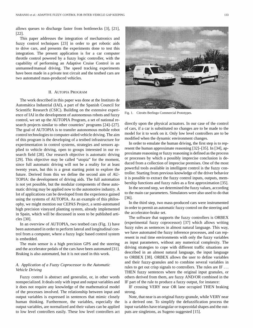
In an overview of AUTOPIA, two testbed cars (Fig. 1) havebeen automated in order to perform lateral and longitudinal con-trol from a computer, where a fuzzy logic based control systemis embedded.
The main sensor is a high precision GPS and the steeringand the accelerator pedals of the cars have been automated [31].Braking is also automated, but it is not used in this work.
A. Application of a Fuzzy Coprocessor to the AutomaticVehicle Driving
Fuzzy control is abstract and generalist, or, in other wordsnonspecialized. It deals only with input and output variables andit does not require any knowledge of the mathematical modelof the processes involved. The relationship between input andoutput variables is expressed in sentences that mimic closelyhuman thinking. Furthermore, the variables, especially theoutput variables, are normalized and their values can be appliedto low level controllers easily. These low level controllers act
Fig. 1. Citroën Berlingo Commercial Prototypes.
directly upon the physical actuators. In our case of the controlof cars, if a car is substituted no changes are to be made to themodel for it to work on it. Only low level controllers are to bemodified when the dynamic environment changes.
In order to emulate the human driving, the first step is to rep-resent the human approximate reasoning [32]–[35]. In [34], ap-proximate reasoning or fuzzy reasoning is defined as the processor processes by which a possibly imprecise conclusion is de-duced from a collection of imprecise premises. One of the mostpowerful tools available in intelligent control is the fuzzy con-troller. Starting from previous knowledge of the driver behaviorit is possible to extract the fuzzy control inputs, outputs, mem-bership functions and fuzzy rules as a first approximation [35].
In the second step, we determined the fuzzy values, accordingto the main car parameters. Simulators were also used to do that[36].
In the third step, two mass-produced cars were instrumentedin order to permit an automatic fuzzy control on the steering andthe accelerator-brake set.
The software that supports the fuzzy controllers is ORBEX(experimental fuzzy coprocessor) [37] which allows writingfuzzy rules as sentences in almost natural language. This way,we have automated the fuzzy inference processes, and can rep-resent in real time environments with only the fuzzy variablesas input parameters, without any numerical complexity. Thedriving strategies to cope with different traffic situations aredescribed in an almost natural language, the input languageto ORBEX [38]. ORBEX allows the user to define variablesand their fuzzy-granules and to combine several variables inrules to get out crisp signals to controllers. The rules are IFTHEN fuzzy sentences where the original input granules, orothers derived from them, are fuzzy AND/OR combined in theIF part of the rule to produce a fuzzy output, for instance:
IF crossing VERY near OR lane occupied THEN brakingstrong.
Note, that near is an original fuzzy-granule, while VERY nearis a derived one. To simplify the defuzzification process theinput variables have triangular or trapezoidal shapes and the out-puts are singletons, as Sugeno suggested [15].
134 IEEE TRANSACTIONS ON INTELLIGENT TRANSPORTATION SYSTEMS, VOL. 4, NO. 3, SEPTEMBER 2003
Two independent controllers have been designed in order toperform automatic driving: lateral control and longitudinal con-trol or, in other words, steering control and speed control respec-tively [39].
We will describe the longitudinal control and the actual re-sults when it is installed in an automated car.
B. Longitudinal Control
Conceptually, in human driving there are three control levelsfor managing the accelerator of a traditional mass-produced car.A mechanical layer (the accelerator pedal and all the associatedhydraulic mechanisms), an actuation layer (the human foot thatsteps on the pedal) and a knowledge reasoning layer (the humanbrain).
The testbed cars used in our study are Citroën Berlingo elec-trical vans, equipped with automatic gearbox in order to sim-plify the gear change. This is a new generation car with a dif-ference between it and the older models: the accelerator pedalconstitutive elements are not mechanical but electronic. A po-tentiometer is installed in this pedal and, when the driver stepson it, an electrical signal is sent to the car’s on-board computerthat moves the wheels at a proportional speed.
In a similar way, when we automate this element of the carwe also divide the control architecture into three layers:
A mechanical layer, identical to the human one, because it isforbidden to change the car components. The difference is thatthe input is not a mechanical pressure over the pedal, but anelectrical signal simulating the signal output of the pedal poten-tiometer.
An electronic layer that, similar to the driver’s foot, generatesa signal proportional to a desired speed.
A control layer made up of a fuzzy control system and aknowledge base.
1) Mechanical Layer:The accelerator pedal of the CitroënBerlingo van has a signal potentiometer associated with it. Thepotentiometer output signal is sent to the car’s internal on-boardcomputer through an electronic interface.
2) Electronic Layer: Two components realize the task ofthe human foot. The first component is an industrial computerin which the control software is executed. The motherboardof this computer is an ICP Robo-505, with a Pentium 166MHz processor, embedded in an industrial PC chassis. Thesecond component is an interface between the PC and the car’son-board computer. The input to this interface is the controlsystem speed command, transmitted through a DB9 RS-232port, and the output is the simulated accelerator potentiometersignal. Therefore we have two accelerator signals: the manualsignal and the automatic signal. A switch is used for selectingone of them when necessary. A second functionality is added tothe electronic layer: the reading of the vehicle speed from thecar’s control panel speedometer. This information is generatedby the car’s internal on-board computer, acquired by the elec-tronic interface and sent to the computer through the RS-232bidirectional link. This speed measurement has an absoluteerror of wheel turn/sampling interval, which is low enoughto achieve good control.
The car speedometer works with a digital signal the wheelsends. Actually a signal is sent whenever the wheel performs
of a turn. We measure the velocity counting this time, witha clock of 10 MHz. The error is negligible unless the speed istoo low. The sampling is performed once every of a second(the loop refresh rate) thus the speed error is turn dividedby second the absolute error is km/hr.
Three commands are available for the interface card:Speed Request:The control system in the PC sends the
hexadecimal value 01. The card returns a 4 byte value with theinstant speed.
Set Watchdog:The control system in the PC sends thehexadecimal value 02, followed by a value between 0 to 7 thatrepresents the duration of the watchdog. This command is usedfor maintaining the card under control when the communicationlink fails. The card answers an echo as acknowledgment.
Set Desired Speed:The control system in the PC sendsany hexadecimal value between 00 H and FFH, except 01 H and02 H. 00 H represents a signal of 1 V at the accelerator (pedalmax. up), and FFH represents 4 V (pedal max. down).
3) Control Layer: Once the system actuators and the elec-tronic environment are defined, we proceed with the definitionof the intelligent control system used for longitudinally control-ling the testbed cars. This system is based on fuzzy logic em-bedded in a hierarchic architecture and it is associated with apowerful world model. In this paper we emphasize the descrip-tion of the fuzzy controller, which carries out the tasks of main-tenance of the speed (CC) and adapting to the lane speed (ACC).
In a short description of our fuzzy controller, it uses thet-norm minimum in order to implementAND operator. Thet-conorm maximum is used in order to implementOR operator.The syntax of the fuzzy rules is defined as:
IF X [OR/AND Z] THEN Y.
WhereX andZ are fuzzy input variables andY is the fuzzyoutput variable. Center of mass method implements the defuzzi-fication operation [40], as shown in (1)
(1)
where represents the value of the weight of each rulei andis the crisp value of each rulei condition, understanding weightas the degree in which the crisp current values of the inputssatisfy the set of rule condition.
A more extensive description of the ORBEX fuzzy copro-cessor can be found in [41]
A PD fuzzy controller has been defined in order to achievethese related tasks. The first step of this development was theCC fuzzy system. After that, and based on the same controller,we developed the second step in our research, the addition ofadaptive capabilities to the CC controller in order to achieve anACC system.
a) The Fuzzy Cruise Control System:The equippedtestbed vehicle provides the necessary data to obtain the inputinformation for the control system: the instantaneous speedand the time interval between two speed measures. This inputconsists of two fuzzy variables:

NARANJO et al.: ADAPTIVE FUZZY CONTROL FOR INTER-VEHICLE GAP KEEPING 135
Fig. 2. CC system diagram.
Fig. 3. Speed Error membership function after the applying MORE THANand LESS THAN modifiers.
Speed Erroris the difference between the current speed andthe user-preset speed. We can express it mathematically as fol-lows in (2).
(2)
Accelerationis approximated by the derivative of the speedfor the instant , described in expression (3).
(3)For an optimal calculation of the acceleration it is essential
to have a precise measurement of the time interval. We use thelow-level clock of the PC for measuring time with an accu-racy of 1/1 193 180 s. The measure even if somehow noisy, isgood enough for our purposes. However a Fourier Filter [42]improves considerably this measure.
The output of the fuzzy controller will be the new acceler-ator-pedal-pressure-like signal (electrical voltage) that will besent to the car internal on-board computer through the electroniclayer. Schematically we can represent the fuzzy PD controller asshown in Fig. 2, where inputs to the fuzzy controller are normal-ized between 0 and 1. The output is also a value in therange, which stands for the increment (or decrement) that mustbe applied to the throttle to achieve the desired speed.
Let us define now the fuzzy membership functions of thesystem variables. There are three membership functions, two pereach input variable and one for the output result.
Speed Error Membership Functions:This input variableis measured in kilometers per hour and defines the profile of thespeed error with only one linguistic label named “null,” scaledbetween 0 and 1 (Fig. 3). Only this label is required becauseORBEX allows fuzzy modifiers like MORE THAN or LESSTHAN to be used.
Because of the use of these kind of modifiers, the fuzzy la-bels MORE THAN null and LESS THAN null can be generated(Fig. 3).
When the speed error is more than null, it means that the realspeed is higher than the user desired speed so the accelerator
Fig. 4. Acceleration membership function after applying MORE THAN andLESS THAN modifiers.
Fig. 5. CC fuzzy controller output.
pedal must move up. If the speed error is less than null, it meansthat the car runs slower that it should so the system must accel-erate. The Fig. 3 shows that the membership functions are notsymmetrical. The dynamics of the vehicle and the mechanicalactuation when the car brakes or accelerates are the reasons forthis asymmetry.
Acceleration Membership Functions:In order touse intuitive units, this input variable is measured inkilometers/hourSecond. Usually, the car tachometer unitsare kilometers per hour, and the acceleration shows the speedincrement per second, a very easy representation for userunderstanding. There is also only a linguistic label named“null” that is normalized between 0 and 1 (Fig. 4). As with thespeed error variable, we use fuzzy modifiers.
With the application of the relational operators LESS THANand MORE THAN, the membership function is transformed likeshown in Fig. 4.
The acceleration is more than null means the car is speedingup; if it is less than null, the car is speeding down. The asym-metry of the functions is due to vehicle dynamics in braking andaccelerating.
The controller output is the stepping on the accelerator pedal,performed through an electrical signal. The fuzzy controlleradds a weight to this output between 0 to 1 in two linguisticslabels; the “Up” label means the control must release theaccelerator pedal and the “Down” label means the control muststep on this pedal. This output is incremental because it is addedto the accumulated value of the accelerator in each control loopiteration. Its membership function is shown in Fig. 5.
Finally, we define the fuzzy rules of the CC control system.Only four rules are necessary:
136 IEEE TRANSACTIONS ON INTELLIGENT TRANSPORTATION SYSTEMS, VOL. 4, NO. 3, SEPTEMBER 2003
(a)
(b)
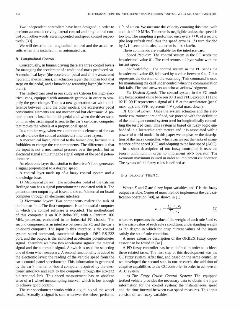
Fig. 6. (a) Assertion of “�5 km/h is LESS THAN null.” (b) Assertion of “10km/h/s is MORE THAN null.”
IF SpeedError MORE THAN null THEN Acceleratorup
IF SpeedError LESS THAN null THEN Accelerator down
IF AccelerationMORE THAN null THEN Acceleratorup
IF AccelerationLESS THAN null THEN Acceleratordown
In order to show the power of ORBEX, we can combine theserules into the following two rules:
IF SpeedError MORE
THAN null OR AccelerationMORE THAN null THEN Acceleratorup
IF SpeedError LESS
THAN null OR AccelerationLESS THAN null THEN Acceleratordown
The SpeedError is the proportional component of the controland the Acceleration is the derivative component. This meansthat, when the speed of the car is not at the desired value, theSpeedError adjusts the throttle pressure order, and the Accel-eration smoothes out the actuation of this command.
Let us give a short overview of how a fuzzy control systemcan be implemented so that computationally cryptic statements(although easily understandable by a person) such us the pre-ceding ones can yield a number to feed a digital to analog con-verter.
Speederror and acceleration are fuzzy input variables andaccelerator is an output variable represented by a singleton.Figs. 3 and 4 show the degree up to which the numerical valuesof Speederror and acceleration satisfy the assertions “null,”“LESS THAN null” or “MORE THAN null.” Note, that infuzzy control, input variables have a numeric value. Thus, inour example we will assume
Fig. 3 shows the degree up to which an assertion such as “5km/h is LESS THAN null” is true. In our case in Fig. 6(a) we seethis degree is 0.33. In a similar way we see in Fig. 6(b) that thedegree up to which the assertion “10 km/hs is MORE THAN
null” is 0.76. From Figs. 3 and 4 we find that both assertions “5 km/h is MORE THAN null” and “10 km/hs is LESS THANnull” have a truth degree of 0.
The above paragraph can be rewritten saying that the fuzzifiedvalue of the assertion “the speed error is lower than null” is 0.33and that of “the acceleration is more than null” is 0.76. The othertwo rules have a truth degree of 0. Then only the rules:
IF Speederror LESS THAN null THEN Acceleratordown
IF AccelerationMORE THAN null THEN Acceleratorup
are to be applied, with a weight 0.33 for the first rule and 0.76for the second.
Now, the controller applies the Center of Mass defuzzificationmethod, and the output for the accelerator pedal will be (1).The output fuzzy variable accelerator has two linguistic valuesUP and DOWN, represented by singletons 1 and. Thus, theoutput is computed in (4).
(4)
This means that the fuzzy controller will send a command tothe accelerator low-level controller, normalized from1 to 1:in this case 0.39. The low-level controller will increment ordecrement its actual pressure over the throttle by a proportionalvalue to this output.
b) The Adaptive Fuzzy Cruise Control System:Thissecond control system is based on the above-mentioned fuzzyCC, with its objective being to maintain a safe gap with the ve-hicle ahead in the same lane of the road. This operation impliesa speed adaptation to the speed of the preceding vehicle thatmust be done automatically by the controller, overriding the CCspeed maintenance of the desired speed. The main applicationof this controller is in highway driving and platoons, in orderto improve the safety and the comfort of driver and passengersin a high-speed driving environment. The extreme situation iswhen the preceding car stops; then the ACC equipped car muststop too. This is a classical event in traffic jam driving, and isgenerically named Stop&Go. Let it be clear that this is not adifferent controller; it is an upgrade of the previous controller.If no other car is detected or the time-gap with a detected car islong enough, this control works as the previous.
The keeping of a user defined safe distance from the nextvehicle is a speed dependent function. This means that the inter-vehicle gap is to be larger as the speed is higher. This is theTime-Headway concept basis: a time dependent safe distancefrom the preceding car. For example, if we set a safe time-gap of2 s when we drive at 40 km/h, the space-gap is 22.2 m but if ourspeed is 100 km/h, this gap is about 55.5 m. The setting of thetime gap depends on the braking power of the car, the weather,the maximum driving speed, etc. For example, in Article 54 ofthe Spanish Highway Code the following is stated:
“The driver of a vehicle driven behind another shall leave agap between them that permits the vehicle to stop in case of asudden brake, without a collision, taking into account the speed,adherence and braking conditions.”
NARANJO et al.: ADAPTIVE FUZZY CONTROL FOR INTER-VEHICLE GAP KEEPING 137
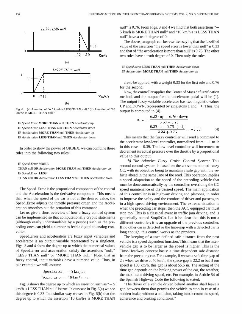
Fig. 7. ACC controller schematic.
Two new input fuzzy variables, a new rule and two rule mod-ifications were added to the controller in order to perform theACC. The output is the same as that in the CC controller: theactuation over the throttle pedal.
When we define this controller and its associated experi-ments, we will introduce a new terminology. We will name aspursued car the human driven vehicle that is driven in front ofthe ACC equipped car. The pursuer car will be the automaticallydriven vehicle that adapts its speed to the preceding one. At thispoint, we shall define the new input variables.
TimeGap Current: It is the time headway, the time ittakes the pursuer vehicle to reach the point where the pursuedvehicle is at present speed, in seconds. The mathematicalrepresentation is (5)
(5)
where and are the x coordinate of the pur-sued and the pursuer cars over the reference line, in meters, and
is the speed of the pursuer car in meters per second.TimeGap Target: It is the time-headway set by the user to
be maintained by the ACC system from the preceding vehicle.In commercial vehicles it should be between 1 and 2 s.
Derivative of TimeGap: Is the variation of theTime-Gapcurrent with time. Its mission is to smooth theactuation in the same way that the Acceleration smoothes theSpeedError. The equation used to calculate this variable forthe control iterationi is (6)
(6)
This variable is very unstable because it fluctuates wildly be-tween positive and negative values easily in consecutive controliterations. An average filter is used for stabilizing the systemand the fourth part of the Time-Gap increment in the last fouriterations is used. This filter is very simple but it is enough inorder to stabilize the variable for a good control, as shown inexperiments.
A new sensor has to be added in order to obtain the infor-mation of the preceding car location. The control level is indif-ferent to the source of the data because the system will work cor-rectly with any sensor that supplies the required position suchas a laser, radar or a Radio-Ethernet link, which is what wasused in our case [43]. All the cars involved in our experimentsare equipped with an RTK-GPS and a Radio-Ethernet environ-ment access; their positions are transmitted in a continuous loopand every car knows at every moment where the other is. The
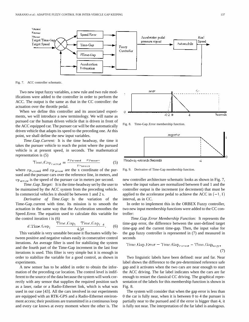
Fig. 8. Time-GapError membership function.
Fig. 9. Derivative of Time-Gap membership function.
new controller architecture schematic looks as shown in Fig. 7,where the input values are normalized between 0 and 1 and thecontroller output is the increment (or decrement) that must beapplied to the accelerator pedal to achieve the ACC ininterval, as in CC.
In order to implement this in the ORBEX Fuzzy controller,two new input membership functions were added to the CC con-troller:
TimeGap Error Membership Function:It represents thetime-gap error, the difference between the user-defined targettime-gap and the current time-gap. Then, the input value forthe gap fuzzy controller is represented in (7) and measured inseconds
(7)
Two linguistic labels have been defined: near and far. Nearlabel shows the difference to the pre-determined reference safegap and it activates when the two cars are near enough to startthe ACC driving. The far label indicates when the cars are farenough to restart the classical CC driving. The graphical repre-sentation of the labels for this membership function is shown inFig. 8.
The system will consider that when the gap error is less than0 the car is fully near, when it is between 0 to 4 the pursuer ispartially near to the pursued and if the error is bigger than 4, itis fully not near. The interpretation of the far label is analogous.
138 IEEE TRANSACTIONS ON INTELLIGENT TRANSPORTATION SYSTEMS, VOL. 4, NO. 3, SEPTEMBER 2003
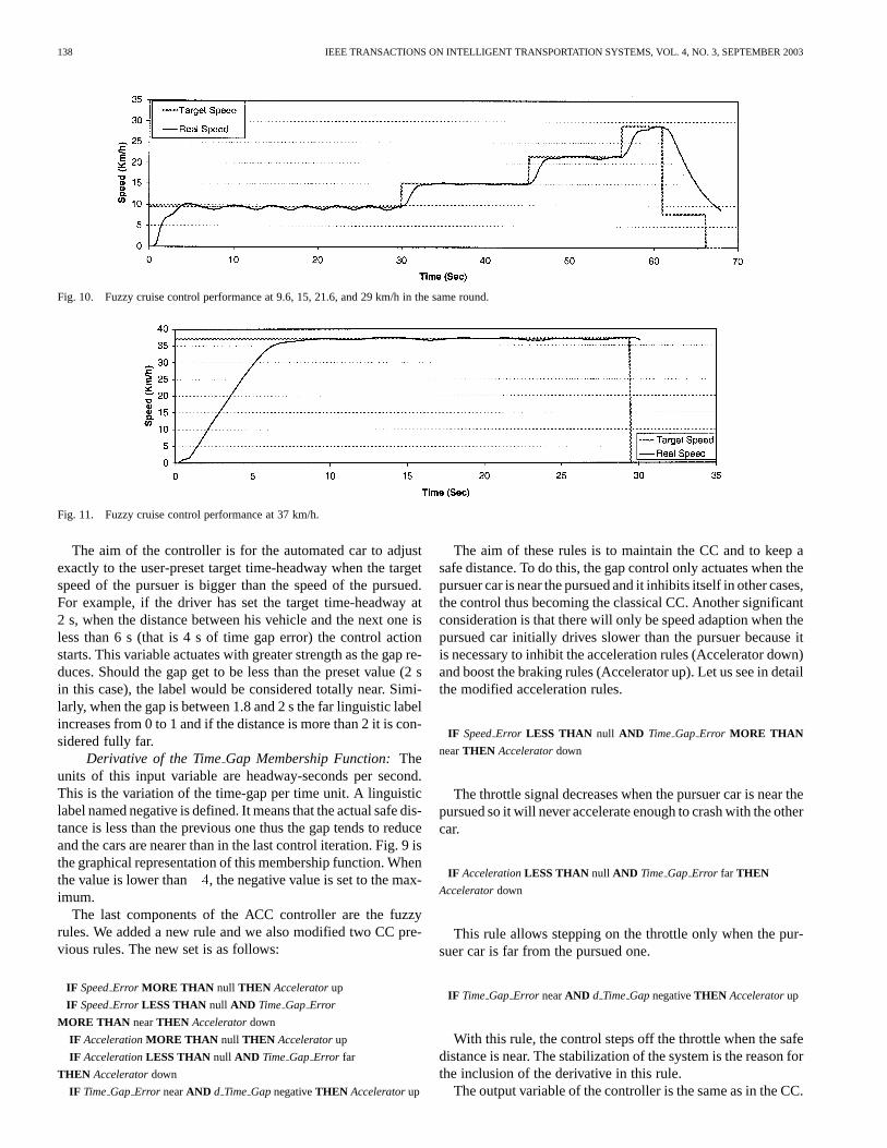
Fig. 10. Fuzzy cruise control performance at 9.6, 15, 21.6, and 29 km/h in the same round.
Fig. 11. Fuzzy cruise control performance at 37 km/h.
The aim of the controller is for the automated car to adjustexactly to the user-preset target time-headway when the targetspeed of the pursuer is bigger than the speed of the pursued.For example, if the driver has set the target time-headway at2 s, when the distance between his vehicle and the next one isless than 6 s (that is 4 s of time gap error) the control actionstarts. This variable actuates with greater strength as the gap re-duces. Should the gap get to be less than the preset value (2 sin this case), the label would be considered totally near. Simi-larly, when the gap is between 1.8 and 2 s the far linguistic labelincreases from 0 to 1 and if the distance is more than 2 it is con-sidered fully far.
Derivative of the TimeGap Membership Function:Theunits of this input variable are headway-seconds per second.This is the variation of the time-gap per time unit. A linguisticlabel named negative is defined. It means that the actual safe dis-tance is less than the previous one thus the gap tends to reduceand the cars are nearer than in the last control iteration. Fig. 9 isthe graphical representation of this membership function. Whenthe value is lower than , the negative value is set to the max-imum.
The last components of the ACC controller are the fuzzyrules. We added a new rule and we also modified two CC pre-vious rules. The new set is as follows:
IF SpeedError MORE THAN null THEN Acceleratorup
IF SpeedError LESS THAN null AND Time Gap Error
MORE THAN nearTHEN Acceleratordown
IF AccelerationMORE THAN null THEN Acceleratorup
IF AccelerationLESS THAN null AND Time Gap Error far
THEN Acceleratordown
IF Time Gap Error nearAND d Time GapnegativeTHEN Acceleratorup
The aim of these rules is to maintain the CC and to keep asafe distance. To do this, the gap control only actuates when thepursuer car is near the pursued and it inhibits itself in other cases,the control thus becoming the classical CC. Another significantconsideration is that there will only be speed adaption when thepursued car initially drives slower than the pursuer because itis necessary to inhibit the acceleration rules (Accelerator down)and boost the braking rules (Accelerator up). Let us see in detailthe modified acceleration rules.
IF SpeedError LESS THAN null AND Time Gap Error MORE THAN
nearTHEN Acceleratordown
The throttle signal decreases when the pursuer car is near thepursued so it will never accelerate enough to crash with the othercar.
IF AccelerationLESS THAN null AND Time Gap Error far THEN
Acceleratordown
This rule allows stepping on the throttle only when the pur-suer car is far from the pursued one.
IF Time Gap Error nearAND d Time GapnegativeTHEN Acceleratorup
With this rule, the control steps off the throttle when the safedistance is near. The stabilization of the system is the reason forthe inclusion of the derivative in this rule.
The output variable of the controller is the same as in the CC.
NARANJO et al.: ADAPTIVE FUZZY CONTROL FOR INTER-VEHICLE GAP KEEPING 139
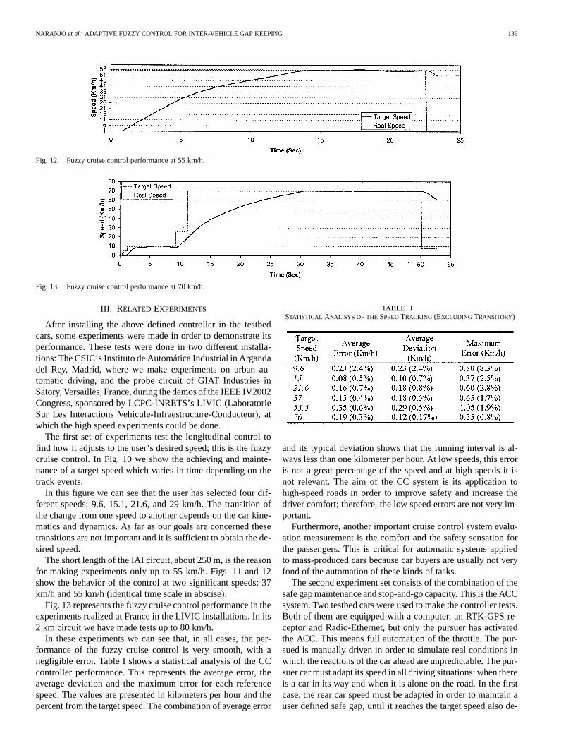
Fig. 12. Fuzzy cruise control performance at 55 km/h.
Fig. 13. Fuzzy cruise control performance at 70 km/h.
III. RELATED EXPERIMENTS
After installing the above defined controller in the testbedcars, some experiments were made in order to demonstrate itsperformance. These tests were done in two different installa-tions: The CSIC’s Instituto de Automática Industrial in Argandadel Rey, Madrid, where we make experiments on urban au-tomatic driving, and the probe circuit of GIAT Industries inSatory, Versailles, France, during the demos of the IEEE IV2002Congress, sponsored by LCPC-INRETS’s LIVIC (LaboratorieSur Les Interactions Vehicule-Infraestructure-Conducteur), atwhich the high speed experiments could be done.
The first set of experiments test the longitudinal control tofind how it adjusts to the user’s desired speed; this is the fuzzycruise control. In Fig. 10 we show the achieving and mainte-nance of a target speed which varies in time depending on thetrack events.
In this figure we can see that the user has selected four dif-ferent speeds; 9.6, 15.1, 21.6, and 29 km/h. The transition ofthe change from one speed to another depends on the car kine-matics and dynamics. As far as our goals are concerned thesetransitions are not important and it is sufficient to obtain the de-sired speed.
The short length of the IAI circuit, about 250 m, is the reasonfor making experiments only up to 55 km/h. Figs. 11 and 12show the behavior of the control at two significant speeds: 37km/h and 55 km/h (identical time scale in abscise).
Fig. 13 represents the fuzzy cruise control performance in theexperiments realized at France in the LIVIC installations. In its2 km circuit we have made tests up to 80 km/h.
In these experiments we can see that, in all cases, the per-formance of the fuzzy cruise control is very smooth, with anegligible error. Table I shows a statistical analysis of the CCcontroller performance. This represents the average error, theaverage deviation and the maximum error for each referencespeed. The values are presented in kilometers per hour and thepercent from the target speed. The combination of average error
TABLE ISTATISTICAL ANALISYS OF THESPEEDTRACKING (EXCLUDING TRANSITORY)
and its typical deviation shows that the running interval is al-ways less than one kilometer per hour. At low speeds, this erroris not a great percentage of the speed and at high speeds it isnot relevant. The aim of the CC system is its application tohigh-speed roads in order to improve safety and increase thedriver comfort; therefore, the low speed errors are not very im-portant.
Furthermore, another important cruise control system evalu-ation measurement is the comfort and the safety sensation forthe passengers. This is critical for automatic systems appliedto mass-produced cars because car buyers are usually not veryfond of the automation of these kinds of tasks.
The second experiment set consists of the combination of thesafe gap maintenance and stop-and-go capacity. This is the ACCsystem. Two testbed cars were used to make the controller tests.Both of them are equipped with a computer, an RTK-GPS re-ceptor and Radio-Ethernet, but only the pursuer has activatedthe ACC. This means full automation of the throttle. The pur-sued is manually driven in order to simulate real conditions inwhich the reactions of the car ahead are unpredictable. The pur-suer car must adapt its speed in all driving situations: when thereis a car in its way and when it is alone on the road. In the firstcase, the rear car speed must be adapted in order to maintain auser defined safe gap, until it reaches the target speed also de-
140 IEEE TRANSACTIONS ON INTELLIGENT TRANSPORTATION SYSTEMS, VOL. 4, NO. 3, SEPTEMBER 2003
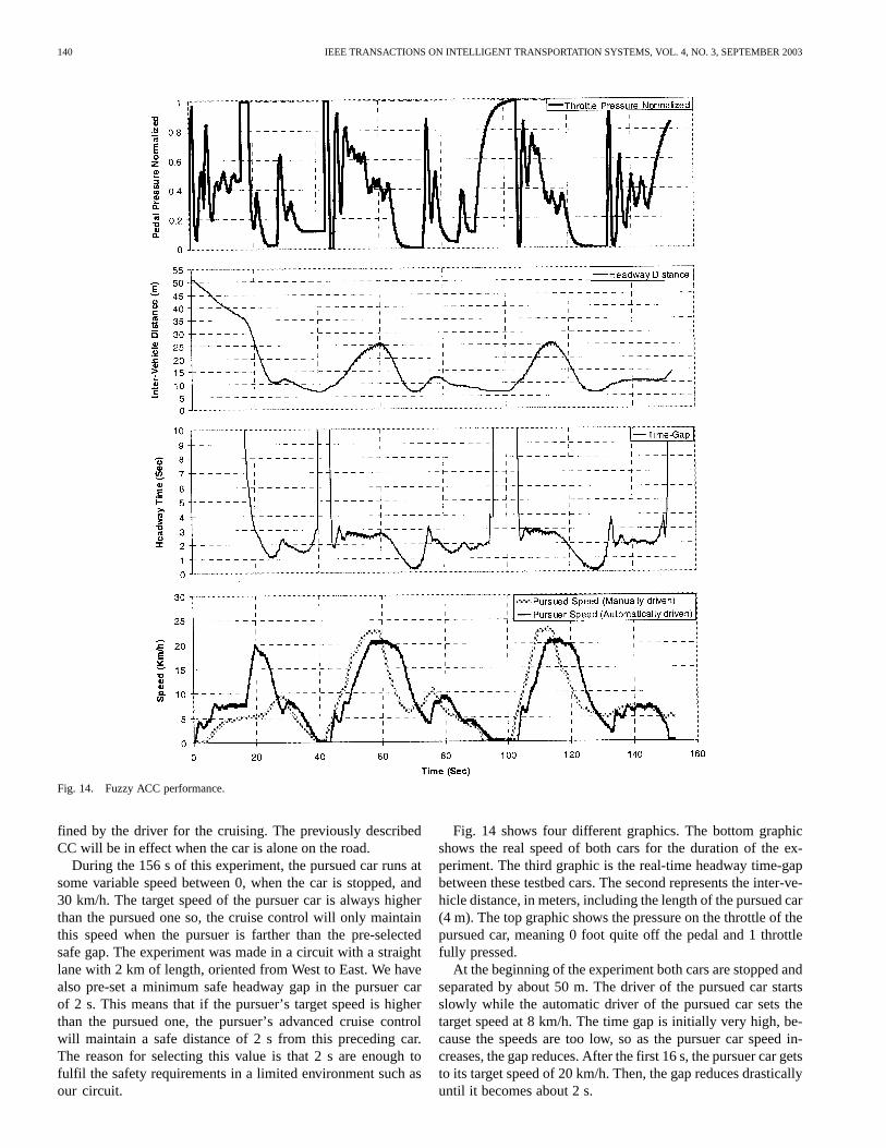
Fig. 14. Fuzzy ACC performance.
fined by the driver for the cruising. The previously describedCC will be in effect when the car is alone on the road.
During the 156 s of this experiment, the pursued car runs atsome variable speed between 0, when the car is stopped, and30 km/h. The target speed of the pursuer car is always higherthan the pursued one so, the cruise control will only maintainthis speed when the pursuer is farther than the pre-selectedsafe gap. The experiment was made in a circuit with a straightlane with 2 km of length, oriented from West to East. We havealso pre-set a minimum safe headway gap in the pursuer carof 2 s. This means that if the pursuer’s target speed is higherthan the pursued one, the pursuer’s advanced cruise controlwill maintain a safe distance of 2 s from this preceding car.The reason for selecting this value is that 2 s are enough tofulfil the safety requirements in a limited environment such asour circuit.
Fig. 14 shows four different graphics. The bottom graphicshows the real speed of both cars for the duration of the ex-periment. The third graphic is the real-time headway time-gapbetween these testbed cars. The second represents the inter-ve-hicle distance, in meters, including the length of the pursued car(4 m). The top graphic shows the pressure on the throttle of thepursued car, meaning 0 foot quite off the pedal and 1 throttlefully pressed.
At the beginning of the experiment both cars are stopped andseparated by about 50 m. The driver of the pursued car startsslowly while the automatic driver of the pursued car sets thetarget speed at 8 km/h. The time gap is initially very high, be-cause the speeds are too low, so as the pursuer car speed in-creases, the gap reduces. After the first 16 s, the pursuer car getsto its target speed of 20 km/h. Then, the gap reduces drasticallyuntil it becomes about 2 s.
NARANJO et al.: ADAPTIVE FUZZY CONTROL FOR INTER-VEHICLE GAP KEEPING 141
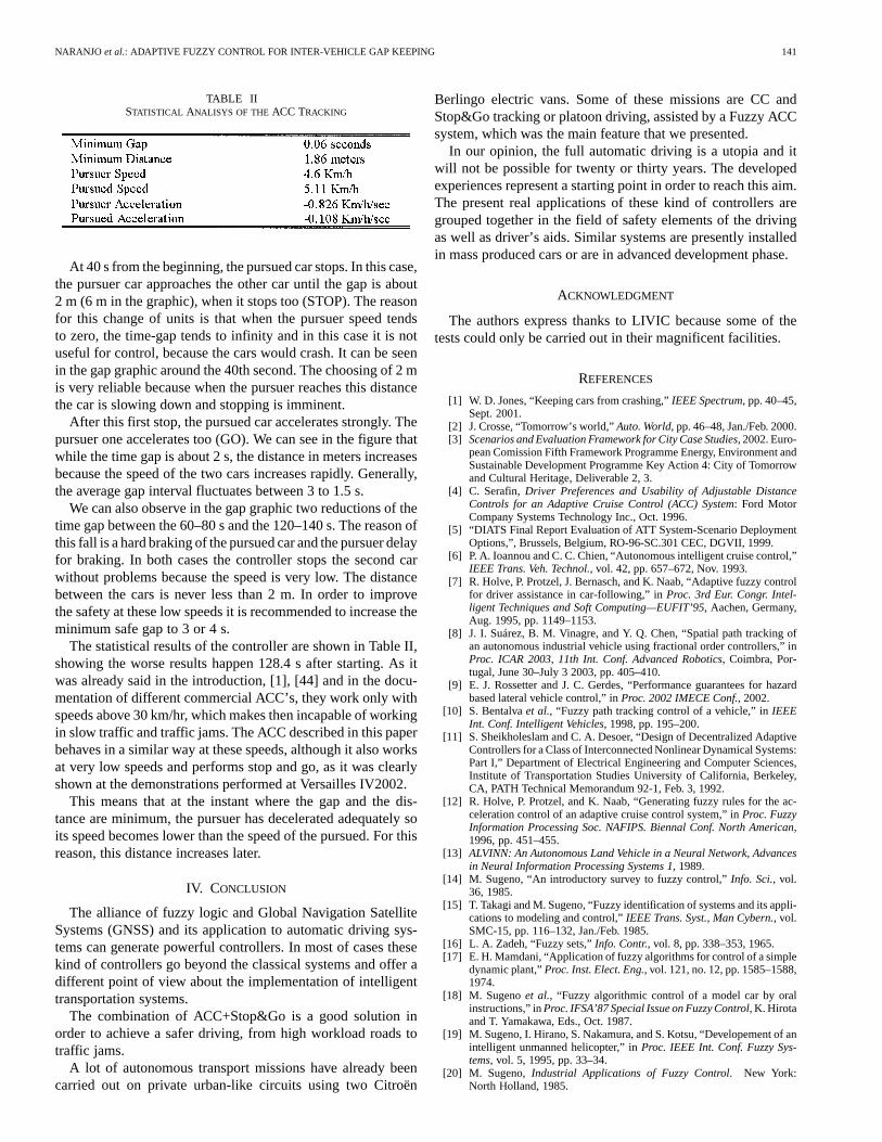
TABLE IISTATISTICAL ANALISYS OF THE ACC TRACKING
At 40 s from the beginning, the pursued car stops. In this case,the pursuer car approaches the other car until the gap is about2 m (6 m in the graphic), when it stops too (STOP). The reasonfor this change of units is that when the pursuer speed tendsto zero, the time-gap tends to infinity and in this case it is notuseful for control, because the cars would crash. It can be seenin the gap graphic around the 40th second. The choosing of 2 mis very reliable because when the pursuer reaches this distancethe car is slowing down and stopping is imminent.
After this first stop, the pursued car accelerates strongly. Thepursuer one accelerates too (GO). We can see in the figure thatwhile the time gap is about 2 s, the distance in meters increasesbecause the speed of the two cars increases rapidly. Generally,the average gap interval fluctuates between 3 to 1.5 s.
We can also observe in the gap graphic two reductions of thetime gap between the 60–80 s and the 120–140 s. The reason ofthis fall is a hard braking of the pursued car and the pursuer delayfor braking. In both cases the controller stops the second carwithout problems because the speed is very low. The distancebetween the cars is never less than 2 m. In order to improvethe safety at these low speeds it is recommended to increase theminimum safe gap to 3 or 4 s.
The statistical results of the controller are shown in Table II,showing the worse results happen 128.4 s after starting. As itwas already said in the introduction, [1], [44] and in the docu-mentation of different commercial ACC’s, they work only withspeeds above 30 km/hr, which makes then incapable of workingin slow traffic and traffic jams. The ACC described in this paperbehaves in a similar way at these speeds, although it also worksat very low speeds and performs stop and go, as it was clearlyshown at the demonstrations performed at Versailles IV2002.
This means that at the instant where the gap and the dis-tance are minimum, the pursuer has decelerated adequately soits speed becomes lower than the speed of the pursued. For thisreason, this distance increases later.
IV. CONCLUSION
The alliance of fuzzy logic and Global Navigation SatelliteSystems (GNSS) and its application to automatic driving sys-tems can generate powerful controllers. In most of cases thesekind of controllers go beyond the classical systems and offer adifferent point of view about the implementation of intelligenttransportation systems.
The combination of ACC+Stop&Go is a good solution inorder to achieve a safer driving, from high workload roads totraffic jams.
A lot of autonomous transport missions have already beencarried out on private urban-like circuits using two Citroën
Berlingo electric vans. Some of these missions are CC andStop&Go tracking or platoon driving, assisted by a Fuzzy ACCsystem, which was the main feature that we presented.
In our opinion, the full automatic driving is a utopia and itwill not be possible for twenty or thirty years. The developedexperiences represent a starting point in order to reach this aim.The present real applications of these kind of controllers aregrouped together in the field of safety elements of the drivingas well as driver’s aids. Similar systems are presently installedin mass produced cars or are in advanced development phase.
ACKNOWLEDGMENT
The authors express thanks to LIVIC because some of thetests could only be carried out in their magnificent facilities.
REFERENCES
[1] W. D. Jones, “Keeping cars from crashing,”IEEE Spectrum, pp. 40–45,Sept. 2001.
[2] J. Crosse, “Tomorrow’s world,”Auto. World, pp. 46–48, Jan./Feb. 2000.[3] Scenarios and Evaluation Framework for City Case Studies, 2002. Euro-
pean Comission Fifth Framework Programme Energy, Environment andSustainable Development Programme Key Action 4: City of Tomorrowand Cultural Heritage, Deliverable 2, 3.
[4] C. Serafin,Driver Preferences and Usability of Adjustable DistanceControls for an Adaptive Cruise Control (ACC) System: Ford MotorCompany Systems Technology Inc., Oct. 1996.
[5] “DIATS Final Report Evaluation of ATT System-Scenario DeploymentOptions,”, Brussels, Belgium, RO-96-SC.301 CEC, DGVII, 1999.
[6] P. A. Ioannou and C. C. Chien, “Autonomous intelligent cruise control,”IEEE Trans. Veh. Technol., vol. 42, pp. 657–672, Nov. 1993.
[7] R. Holve, P. Protzel, J. Bernasch, and K. Naab, “Adaptive fuzzy controlfor driver assistance in car-following,” inProc. 3rd Eur. Congr. Intel-ligent Techniques and Soft Computing—EUFIT’95, Aachen, Germany,Aug. 1995, pp. 1149–1153.
[8] J. I. Suárez, B. M. Vinagre, and Y. Q. Chen, “Spatial path tracking ofan autonomous industrial vehicle using fractional order controllers,” inProc. ICAR 2003, 11th Int. Conf. Advanced Robotics, Coimbra, Por-tugal, June 30–July 3 2003, pp. 405–410.
[9] E. J. Rossetter and J. C. Gerdes, “Performance guarantees for hazardbased lateral vehicle control,” inProc. 2002 IMECE Conf., 2002.
[10] S. Bentalvaet al., “Fuzzy path tracking control of a vehicle,” inIEEEInt. Conf. Intelligent Vehicles, 1998, pp. 195–200.
[11] S. Sheikholeslam and C. A. Desoer, “Design of Decentralized AdaptiveControllers for a Class of Interconnected Nonlinear Dynamical Systems:Part I,” Department of Electrical Engineering and Computer Sciences,Institute of Transportation Studies University of California, Berkeley,CA, PATH Technical Memorandum 92-1, Feb. 3, 1992.
[12] R. Holve, P. Protzel, and K. Naab, “Generating fuzzy rules for the ac-celeration control of an adaptive cruise control system,” inProc. FuzzyInformation Processing Soc. NAFIPS. Biennal Conf. North American,1996, pp. 451–455.
[13] ALVINN: An Autonomous Land Vehicle in a Neural Network, Advancesin Neural Information Processing Systems 1, 1989.
[14] M. Sugeno, “An introductory survey to fuzzy control,”Info. Sci., vol.36, 1985.
[15] T. Takagi and M. Sugeno, “Fuzzy identification of systems and its appli-cations to modeling and control,”IEEE Trans. Syst., Man Cybern., vol.SMC-15, pp. 116–132, Jan./Feb. 1985.
[16] L. A. Zadeh, “Fuzzy sets,”Info. Contr., vol. 8, pp. 338–353, 1965.[17] E. H. Mamdani, “Application of fuzzy algorithms for control of a simple
dynamic plant,”Proc. Inst. Elect. Eng., vol. 121, no. 12, pp. 1585–1588,1974.
[18] M. Sugenoet al., “Fuzzy algorithmic control of a model car by oralinstructions,” inProc. IFSA’87 Special Issue on Fuzzy Control, K. Hirotaand T. Yamakawa, Eds., Oct. 1987.
[19] M. Sugeno, I. Hirano, S. Nakamura, and S. Kotsu, “Developement of anintelligent unmanned helicopter,” inProc. IEEE Int. Conf. Fuzzy Sys-tems, vol. 5, 1995, pp. 33–34.
[20] M. Sugeno,Industrial Applications of Fuzzy Control. New York:North Holland, 1985.

142 IEEE TRANSACTIONS ON INTELLIGENT TRANSPORTATION SYSTEMS, VOL. 4, NO. 3, SEPTEMBER 2003
[21] M. Persson, F. Botling, E. Hesslow, and R. Johansson, “Stop&go con-troller for adaptive cruise control,” inProc. IEEE Control ApplicationsConf., vol. 2, 1999, pp. 1692–1697.
[22] S. Kato, S. Tsugawa, K. Tokuda, T. Matsui, and H. Fujiri, “Vehicle con-trol algorithms for cooperative driving with automated vehicles and in-tervehicle communications,”IEEE Trans. Intell. Transport. Syst., vol. 3,no. 3, pp. 155–161, Sept. 2002.
[23] M. Sugeno, “Theory of fuzzy integrals and its applications,” Ph.D. dis-sertation, Tokyo Institute of Technology, Japan, 1974.
[24] M. Bursa, “Big names invest heavily in advanced ITS technology,” inISATA Mag., Dec./Jan. 2000, pp. 24–30.
[25] J. M. Blosseville and M. Parent, “The french program: La route automa-tisee,”IEEE Intelligent Syst., pp. 10–13, May/June 2000.
[26] Literature Review of ADAS/AVG (AVCSS) for Japan and United States,June 27, 2001.
[27] R. Bishop, “Intelligent vehicle applications worldwide,”IEEE Intell.Syst., pp. 78–81, Jan./Feb. 2000.
[28] M. A. Sotelo, S. Alcalde, J. Reviejo, J. E. Naranjo, R. Garcia, T.DePedro, and C. Gonzalez, “Vehicle Fuzzy Driving Based on DGPSand Vision,” inProc. 9th IFSA World Congr., Canada, July 2001.
[29] R. García and T. de Pedro, “Automatic car drivers,” presented at theProc. 31th Int. Symp. Automotive Technology and Automation, ISBN 09 532 576 0 6, June 1998.
[30] C. González, J. Reviejo, J. E. Naranjo, R. García, and T. de Pedro, “Sis-tema de ayuda a la plantación de viñas basado en navegación por satélite(GNSS),” presented at the Latin-American Conf. Automatic Control,CLCA 2002, Guadalajara, Mexico, Dec. 2002.
[31] S. Alcalde, “Instrumentación de un Vehículo Eléctrico Para Una Con-ducción Automática,” Degree Thesis, Escuela Universitaria de Infor-mática, Universidad Politécnica de Madrid, Madrid, Spain, Jan. 2000.
[32] L. A. Zadeh, “Fuzzy languages and their relation to human and machineintelligence,” inProc. Man and Computer Processing Int. Conf., Bor-deaux, France, 1970, pp. 130–165.
[33] , Approximate Reasoning Based on Fuzzy Logic. Berkeley, CA:Electronics Research Lab., College of Engineering, Univ. California,May 1979, Memorandum UCB/ERL M79/32.
[34] , A Theory of Approxinate Reasoning, Machine Intelligence 9, J. E.Hayes, D. Michie, and L. I. Mikulich, Eds. New York: Wiley, 1979.
[35] , “A new direction in AI, toward a computational theory of percep-tions,” in AI Mag., Spring 2001, pp. 73–84.
[36] J. Reviejo, T. De Pedro, J. E. Naranjo, R. Garcia, C. Gonzalez, andS. Alcalde, “An open frame to test techniques and equipment forautonomous vehicles,” inProc. IFAC-MIM 2000, Patras, Greece, July2000, pp. 350–354.
[37] R. Garcia and T. De Pedro, “Modeling a fuzzy coprocessor and its pro-gramming language,”Mathware and Soft Computing, vol. V, no. 2–3,pp. 167–174, 1998.
[38] , “First application of the ORBEX coprocessor: Control ofunmanned vehicles,” inProc. EUSFLAT-ESTYLF Joint Conf., vol. 2–3,2000, pp. 265–273.
[39] R. Garcia, T. De Pedro, J. E. Naranjo, J. Reviejo, and C. Gonzalez,“Frontal and lateral control for unmanned vehicles in urban tracks,” pre-sented at the IEEE Intelligent Vehicle Symp., June 2002.
[40] A. V. Patel and B. M. Mohan, “Some numerical aspect of center of areadefuzzification method,”Fuzzy Sets and Syst., vol. 132, pp. 401–409,2002.
[41] R. García and T. de Pedro, “A powerful model for a fuzzy coprocessor,”presented at the Proc. Congreso Interamericano de Control AutomáticoCLCA’98 & IFAC’98, Chile, 1998.
[42] J.-C. Radix,Introduction au Filtrage Numèrique, Paris: Eyrolles, 1970.[43] J. E. Naranjo, “Sistemas de Comunicaciones Inalámbricos Aplicados a
la Conducción Automática de Vehículos,” Degree thesis, UniversidadPolitécnica de Madrid, Spain, Sept. 2001.
[44] Evaluation of the Intelligent Cruise Control System. Volume I—StudyResults. Cambridge, MA: Volpe National Transportation SystemsCenter, Research and Special Programs Administration.
José E. Naranjowas born in Orense, Spain, in 1975.He received the B.E. and M.E. degrees in computerscience engineering from the Polytechnic Universityof Madrid (UPM), Spain, in 1998 and 2001, respec-tively.
Since 1999, he has been with the the IndustrialComputer Science Department, Instituto de Au-tomtica Industrial (CSIC). His research interestincludes fuzzy logic control and ITS.
Carlos González(M’86) was born in Torrelavega,(Cantabria), Spain, in 1947. He received the B.S. andthe Ph.D. degrees in physics from Madrid University,Madrid, Spain, in 1969 and 1978, respectively, andthe M.S. degree in computer science from the Uni-versity of California at Los Angeles, in 1974.
Since 1971, he has been on staff of the IndustrialAutomation Institute of the Spanish Council for Sci-entific Research, where he is a software specialist forautomation projects.
Jesús Reviejoreceived the B.E. and M.E. degreesin computer science from the Polytechnic Universityof Madrid, Madrid, Spain, in 1989 and 2003 respec-tively.
Since 1989, he has been working at the IndustrialAutomation Institute of the Spanish Council forScientific Research, where from 1989 to 1998, heworked on robotics and walking robots. Since 1999,he has been working on ITS.
Ricardo García received the Ph.D. degree in physicsfrom the Bilbao University, Spain.
He was a Founder of the Industrial Automation In-stitute of the Spanish Council for Scientific Research,where he works on intelligent robotics.
Dr. García was named in 2002 for the “Barreiros”Research on Automotive Field Prize for his AU-TOPIA project on ITS.
Teresa de Pedro received the Ph.D. degree inphysics from the Universidad Complutense ofMadrid, Madrid, Spain, in 1976.
Since 1971, she has been working on artificial in-telligence applied to automation at the Industrial Au-tomation Institute, Spanish Council for Scientific Re-search. She is the Head of a Spanish team involved inthe Integration of Sensors to Active Aided Conduc-tion (ISAAC) project. Her research interests includefuzzy models for unmanned vehicles.
Related Documents