Products Solutions Services TI00426F/00/EN/19.17 71375968 Technical Information Weld-in adapter, Process adapter and Flanges Level and pressure measurement Application The adapters and the flanges are used to connect level or pressure sensors to a vessel or a pipe. Your benefits • High-quality, corrosion resistant materials for use in aggressive media • Versions without crevices and dead space of the weld-in adapters and the process adapters according to international hygiene regulations • A variety of seals for application in diverse processes • Flanges are specified according to both flange standards DIN/EN

Welcome message from author
This document is posted to help you gain knowledge. Please leave a comment to let me know what you think about it! Share it to your friends and learn new things together.
Transcript

Products Solutions ServicesTI00426F/00/EN/19.1771375968
Technical InformationWeld-in adapter, Process adapter and Flanges Level and pressure measurement
ApplicationThe adapters and the flanges are used to connect level or pressure sensors to a vessel or a pipe.
Your benefits
• High-quality, corrosion resistant materials for use in aggressive media• Versions without crevices and dead space of the weld-in adapters and the process
adapters according to international hygiene regulations• A variety of seals for application in diverse processes• Flanges are specified according to both flange standards DIN/EN

Weld-in adapter, process adapter and flanges
2 Endress+Hauser
Table of contents
General information . . . . . . . . . . . . . . . . . . . . . . . . . . . .3Suitable for hygienic processes . . . . . . . . . . . . . . . . . . . . . . . . . . 3
Weld-in adapter - overview level . . . . . . . . . . . . . . . . . .5
Weld-in adapter and accessories - level . . . . . . . . . . . .9G ¾", d=29 for pipe-mounting . . . . . . . . . . . . . . . . . . . . . . . . . . . 9G ¾", d=50 for vessel-mounting . . . . . . . . . . . . . . . . . . . . . . . . 10G ¾", d=55 with flange for flush-mounted installation . . . . . 11G 1", d=53 without flange for pipe-mounting . . . . . . . . . . . . . 12G 1", d=60 with flange for flush-mounted installation . . . . . . 13G 1" sensor can be positioned . . . . . . . . . . . . . . . . . . . . . . . . . . . 14RD 52 sensor can be positioned . . . . . . . . . . . . . . . . . . . . . . . . . 15UNI D85 . . . . . . . . . . . . . . . . . . . . . . . . . . . . . . . . . . . . . . . . . . . . 15UNI D65 . . . . . . . . . . . . . . . . . . . . . . . . . . . . . . . . . . . . . . . . . . . . 16M24 D65 . . . . . . . . . . . . . . . . . . . . . . . . . . . . . . . . . . . . . . . . . . . 16DRD DN50 for flush-mounted installation of devices . . . . . . . 17
Weld-in adapter - overview pressure. . . . . . . . . . . . . 18
Weld-in adapter and accessories - Pressure . . . . . . . 21UNI D85 . . . . . . . . . . . . . . . . . . . . . . . . . . . . . . . . . . . . . . . . . . . . 21UNI D65 . . . . . . . . . . . . . . . . . . . . . . . . . . . . . . . . . . . . . . . . . . . . 22DRD DN50 for flush-mounted install. of devices with DRD-Flange . . . . . . . . . . . . . . . . . . . . . . . . . . . . . . . . . . . . . . . . . . . . . . 23G 1", d=60 with flange for flush-mounted installation with sealing surface . . . . . . . . . . . . . . . . . . . . . . . . . . . . . . . . . . . . . . . 24G 1½" flush-mounted . . . . . . . . . . . . . . . . . . . . . . . . . . . . . . . . . 25G 1" flush-mounted with metallic sealing taper . . . . . . . . . . . . 25G ½" flush-mounted . . . . . . . . . . . . . . . . . . . . . . . . . . . . . . . . . . 25M24 D65 . . . . . . . . . . . . . . . . . . . . . . . . . . . . . . . . . . . . . . . . . . . 26
Process adapter M24 - overview level and pressure 27
Process connection M24 - level and pressure. . . . . . 28Varivent F DN32 PN40 . . . . . . . . . . . . . . . . . . . . . . . . . . . . . . . . 28Varivent N DN50 PN40 . . . . . . . . . . . . . . . . . . . . . . . . . . . . . . . 28DIN11851 DN40 . . . . . . . . . . . . . . . . . . . . . . . . . . . . . . . . . . . . . 29DIN11851 DN50 . . . . . . . . . . . . . . . . . . . . . . . . . . . . . . . . . . . . . 29SMS 1½" . . . . . . . . . . . . . . . . . . . . . . . . . . . . . . . . . . . . . . . . . . . . 30Clamp 1½" . . . . . . . . . . . . . . . . . . . . . . . . . . . . . . . . . . . . . . . . . . . 30Clamp 2" . . . . . . . . . . . . . . . . . . . . . . . . . . . . . . . . . . . . . . . . . . . . 31APV-Inline . . . . . . . . . . . . . . . . . . . . . . . . . . . . . . . . . . . . . . . . . . 31
Process adapter UNI - overview pressure . . . . . . . . . 32
Process adapter UNI - Pressure. . . . . . . . . . . . . . . . . . 33Clamp 2" . . . . . . . . . . . . . . . . . . . . . . . . . . . . . . . . . . . . . . . . . . . . 33Varivent N . . . . . . . . . . . . . . . . . . . . . . . . . . . . . . . . . . . . . . . . . . 33DIN11851 DN40 . . . . . . . . . . . . . . . . . . . . . . . . . . . . . . . . . . . . . 34DIN11851 DN50 . . . . . . . . . . . . . . . . . . . . . . . . . . . . . . . . . . . . . 34DRD DN50 . . . . . . . . . . . . . . . . . . . . . . . . . . . . . . . . . . . . . . . . . . 35
Welding hints . . . . . . . . . . . . . . . . . . . . . . . . . . . . . . . . 36Weld-in adapter with leakage hole or leakage port . . . . . . . . 36Notes for pressure measuring devices . . . . . . . . . . . . . . . . . . . 36
Preparation . . . . . . . . . . . . . . . . . . . . . . . . . . . . . . . . . . . . . . . . . . 36Welding procedure . . . . . . . . . . . . . . . . . . . . . . . . . . . . . . . . . . . 37Install measuring device . . . . . . . . . . . . . . . . . . . . . . . . . . . . . . . 37Pressure resistance . . . . . . . . . . . . . . . . . . . . . . . . . . . . . . . . . . . 38
Flange - Overview . . . . . . . . . . . . . . . . . . . . . . . . . . . . . 39Specifications . . . . . . . . . . . . . . . . . . . . . . . . . . . . . . . . . . . . . . . . 39Versions . . . . . . . . . . . . . . . . . . . . . . . . . . . . . . . . . . . . . . . . . . . . 39Flange Norm DIN EN 1092-1 . . . . . . . . . . . . . . . . . . . . . . . . . . 39Height of raised face . . . . . . . . . . . . . . . . . . . . . . . . . . . . . . . . . . 40
Mechanical Construction . . . . . . . . . . . . . . . . . . . . . . . 41DIN flanges (DIN 2527) . . . . . . . . . . . . . . . . . . . . . . . . . . . . . . . 41PN10 . . . . . . . . . . . . . . . . . . . . . . . . . . . . . . . . . . . . . . . . . . . . . . . 41PN16 . . . . . . . . . . . . . . . . . . . . . . . . . . . . . . . . . . . . . . . . . . . . . . . 42PN25 . . . . . . . . . . . . . . . . . . . . . . . . . . . . . . . . . . . . . . . . . . . . . . . 42PN40 . . . . . . . . . . . . . . . . . . . . . . . . . . . . . . . . . . . . . . . . . . . . . . . 43PN64 . . . . . . . . . . . . . . . . . . . . . . . . . . . . . . . . . . . . . . . . . . . . . . . 43PN100 . . . . . . . . . . . . . . . . . . . . . . . . . . . . . . . . . . . . . . . . . . . . . . 44EN flanges (DIN EN 1092-1) . . . . . . . . . . . . . . . . . . . . . . . . . . . 45PN16 . . . . . . . . . . . . . . . . . . . . . . . . . . . . . . . . . . . . . . . . . . . . . . . 45PN25 . . . . . . . . . . . . . . . . . . . . . . . . . . . . . . . . . . . . . . . . . . . . . . . 45PN40 . . . . . . . . . . . . . . . . . . . . . . . . . . . . . . . . . . . . . . . . . . . . . . . 46PN63 . . . . . . . . . . . . . . . . . . . . . . . . . . . . . . . . . . . . . . . . . . . . . . . 46PN100 . . . . . . . . . . . . . . . . . . . . . . . . . . . . . . . . . . . . . . . . . . . . . . 47ASME-Flange (ASME B16.5-2013) . . . . . . . . . . . . . . . . . . . . . 48Class 150 . . . . . . . . . . . . . . . . . . . . . . . . . . . . . . . . . . . . . . . . . . . 48Class 300 . . . . . . . . . . . . . . . . . . . . . . . . . . . . . . . . . . . . . . . . . . . 49Class 600 . . . . . . . . . . . . . . . . . . . . . . . . . . . . . . . . . . . . . . . . . . . 49Class 900 . . . . . . . . . . . . . . . . . . . . . . . . . . . . . . . . . . . . . . . . . . . 50Class 1500 . . . . . . . . . . . . . . . . . . . . . . . . . . . . . . . . . . . . . . . . . . 50JIS flanges (B 2220) . . . . . . . . . . . . . . . . . . . . . . . . . . . . . . . . . . 5110 K . . . . . . . . . . . . . . . . . . . . . . . . . . . . . . . . . . . . . . . . . . . . . . . . 5120 K . . . . . . . . . . . . . . . . . . . . . . . . . . . . . . . . . . . . . . . . . . . . . . . . 5163 K . . . . . . . . . . . . . . . . . . . . . . . . . . . . . . . . . . . . . . . . . . . . . . . . 52
Pressure-temperature dependencies . . . . . . . . . . . . . 53EN flanges . . . . . . . . . . . . . . . . . . . . . . . . . . . . . . . . . . . . . . . . . . 53ASME flanges . . . . . . . . . . . . . . . . . . . . . . . . . . . . . . . . . . . . . . . . 53JIS flanges . . . . . . . . . . . . . . . . . . . . . . . . . . . . . . . . . . . . . . . . . . . 53
Adapter flange FAU70 . . . . . . . . . . . . . . . . . . . . . . . . . 54FAU70E Version with metrical thread . . . . . . . . . . . . . . . . . . . 54FAU70A Version with conical thread . . . . . . . . . . . . . . . . . . . . 54
Slip-on flange FAU80 . . . . . . . . . . . . . . . . . . . . . . . . . . 55FAU80 Version slip-on flange . . . . . . . . . . . . . . . . . . . . . . . . . . 55
Screw in flange FAX50 . . . . . . . . . . . . . . . . . . . . . . . . . 56FAX50 universal flange DIN-ASME-JIS . . . . . . . . . . . . . . . . . . 56G ¾", NPT ¾" . . . . . . . . . . . . . . . . . . . . . . . . . . . . . . . . . . . . . . . . . 56G 1", NPT 1" . . . . . . . . . . . . . . . . . . . . . . . . . . . . . . . . . . . . . . . . . . 56G 1½", NPT 1½" . . . . . . . . . . . . . . . . . . . . . . . . . . . . . . . . . . . . . . 57G 2", NPT 2" . . . . . . . . . . . . . . . . . . . . . . . . . . . . . . . . . . . . . . . . . . 57Order information FAX50 . . . . . . . . . . . . . . . . . . . . . . . . . . . . . 58

Weld-in adapter, process adapter and flanges
Endress+Hauser 3
General information
Pressure equipment directive PED 2014/68/EU:
The herein listed adapters are not subject to the pressure equipment directive independent of the maximum allowable amount of pressure, because they have no pressurised housing.
NOTICEMaximum pressure and temperature may be limited by the sensor installed in the adapter. ‣ Maximum design pressure and temperature stated is for the adapter only and not for the sensor
being installed in the adapter. Consult sensor supplier for sensor pressure-temperature ratings.
Suitable for hygienic processes
3-A und EHEDG
NOTICE
‣ Depending of device versions meet the requirements of 3-A sanitary standard no. 74. Endress+Hauser confirms this compliance by affixing the 3-A symbol.
‣ For the hygienic design accordingly 3-A, EHEDG and ASME BPE is the use of appropriate fittings for pipings and gaskets should be noted.
‣ To avoid the risk of contamination, install the device in accordance with the design principles of EHEDG, Document 37 "Hygienic Design and Application for Sensors" and Document 16 "Hygienic Pipe Connections".
‣ Suitable connections and seals must be used in order to guarantee hygiene-compliant design as per 3-A and EHEDG specifications.
‣ If installed horizontally, ensure that the leakage hole is pointing downwards. This allows leaks to be detected as quickly as possibles, see chapter "Weld-in adapter with leakage hole/leakage port" ä 34.
‣ The gap-free connections can be cleaned of all residue using sterilization in place (SIP) and cleaning in place (CIP), which are typical cleaning methods within the industry. Attention must be paid to the pressure and temperature specifications of the sensor and process connections for CIP and SIP processes.
Material conformity
Conform materials according to FDA 21 CFR (Code of Federal Regulations)
PART 177 - Indirect Food Additives: Polymers• Part 177.1550: Perfluorocarbon resins (PTFE)• Part 177.2600: Rubber articles intended for repeated use (EPDM, Silicone (VMQ), Viton (FKM))
Conform to regulation (EC) No. 1935/2004 on materials and articles intended to come into contact with food (European)
• BfR (Federal Institute for Risk Assessment) Recommendation XV. Commodities based on Silicones: Silicone (VMQ)
• BfR (Federal Institute for Risk Assessment) Recommendation XXI. Commodities based on Natural and Synthetic Rubber: EPDM, Viton (FKM)
• PTFE conform to regulation (EC) No. 10/2011
NOTICE
‣ The data concerning suitability for hygienic processes are listed under the relevant device version.‣ The weld-in adapters are manufactured according to the material specifications of the latest
standards. Special versions of weld-in adapters, e.g. older material charges, must be requested and ordered via TSP workflow.
74-xx
TYPE EL - CLASS Ixxx

Weld-in adapter, process adapter and flanges
4 Endress+Hauser
Weld-in adapter - overview level
Product Configurator: www.endress.com
Weld-in adapter
a0008246 a0008251 a0008256 a0011924 a0008248 a0008253
G ¾", d=29 for pipe-
mounting
G ¾", d=50 for vessel-mounting
G ¾", d=55 with flange
G 1", d=53 without flange
G 1", d=60 with flange
G 1"adjustable
Material 316L (1.4435) 316L (1.4435) 316L (1.4435) 316L (1.4435) 316L (1.4435) 316L (1.4435)
Roughness μm (μin) process side 1.5 (59.1) 0.8 (31.5) 0.8 (31.5) 0.8 (31.5) 0.8 (31.5) 0.8 (31.5)
Order number weld-in adapter 71258357 71258355 52001052 71258358 520010511) 520012212)
Order number weld-in adapter with inspection certificate3) 4) 52028295 52018765 52011897 71093129 52011896) 52011898)
Order number for seal replacement (5 pieces)5)
Silicone O-ring52021717
Silicone O-ring52021717
Silicone O-ring52014473
Silicone O-ring52014472
Silicone O-ring52014472
Silicone profile gasket
52014424
Order number welding dummy6) 71174959 71174959 71168889 71166879 71166879 71181945
Order number blind plug 71167850 71167850 71177193 71173810 71173810 71166366
Order number blind plug with ins-pection certificate
– – 71190074 71167291 71167291 71196853
Measuring device Suitable for process connectionoption7)
Liquicap
FMI51 – GQJ – GWJ GWJ –
FMI52 – – – GWJ GWJ –
FTI51 – GQJ – GWJ GWJ –
FTI52 – – – GWJ GWJ –
Liquipoint
FTW23, FTW33 W5J W5J – WSJ WSJ –
1) Replace the weld-in adapter with order number 917969-1000.
2) Replace the weld-in adapter with order number 215159-0000.
3) AD2000: The material 316L (in contact with process) corresponds to AD2000 – W0/W2.
4) Inspection certificate EN10204-3.1 material
5) One seal is included in scope of delivery.
6) TSP modification number. Can be ordered only FTSP, PTSP or NTSP.
7) The option can be selected in the Product Configurator via the order feature "Process Connection".

Weld-in adapter, process adapter and flanges
Endress+Hauser 5
Product Configurator: www.endress.com
Weld-in adapter
a0008246 a0008251 a0008256 a0011924 a0008248 a0008253
G ¾", d=29 for pipe-
mounting
G ¾", d=50 for vessel-mounting
G ¾", d=55 with flange
G 1", d=53 without flange
G 1", d=60 with flange
G 1"adjustable
Measuring device Suitable for process connectionoption1)
Liquiphant
FTL33, FTL31 W5J W5J – WSJ WSJ WSJ
FTL20 1 1 – 7 7 7
FTL20H GDJ GDJ – GEJ GEJ GEJ
FTL260 – – – 0 0 –
FTL330x – – – G G G
FTL50, FTL50H – – GQ2 GW2 GW2 GW2
FTL51, FTL51H – – – GW2 GW2 GW2
FTL80 – – WCJ WSJ WSJ WSJ
FTL81 – – – WSJ WSJ WSJ
Adapter as an accessory enclosedoption2)
Liquipoint
FTW23, FTW33 PC/PD PA/PB – PG/PH PE/PF –
Liquiphant
FTL31, FTL33 PC/PD PA/PB – PG/PH PE/PF –
1) The option can be selected in the Product Configurator via the order feature "Process Connection".
2) The option can be selected in the Product Configurator via the order feature "Accessory Enclosed".

Weld-in adapter, process adapter and flanges
6 Endress+Hauser
Product Configurator: www.endress.com
Weld-in adapter
a0008252 a0008245 A0017639 a0008552 a0008254
RD52 UNI D85 UNI D65 M24 D65DRD DN50
65 mm (2.56 in)(weld-in flange)
Material 316L (1.4435) 316L (1.4435) 316L (1.4435) 316L (1.4435)316L (1.4435)304 (1.4301)
Roughness μm (μin) process side 0.8 (31.5) 0.76 (29.9) 0.76 (29.9) 0,76 (29.9) 0.76 (29.9)
Order number weld-in adapter 520010471) 52006262 214880-0002 7104138152002041/
916743-0000
Order number weld-in adapter with inspection certificate2) 52006909) 52010173 52010174 71041383 52011899/ –
Order number for seal replacement (5 pieces)3)
Silicone profile gasket
52014424
Silicone profile gasket
52023572
Silicone profile gasket
52023572
EPDMO-ring
52024267
PTFE flat seal
52024228
Order number welding dummy 711819454) 71114210 71114210 – 71114209
Order number blind plug 71114210 71181340 71181340 71171418 71181450
Slotted nut 52021715 52021715 52021715 – –
Measuring device Suitable for process connectionoption5)
Liquicap
FMI5x – UPJ UPJ – –
FTI5x – UPJ UPJ – –
Liquipoint
FTW23, FTW33 – – – X2J –
Liquiphant
FTL33 5ZJ – – X2J –
FTL20H UPJ – – – –
FTL330x F – – – –
FTL5xH EE2 – – – PE2
1) Replace the weld-in adapter with order number 942329-0001.
2) Inspection certificate EN10204-3.1 material; AD2000: The material 316L (in contact with process) corresponds to AD2000 – W0/W2.
3) One seal is included in scope of delivery.
4) TSP modification number. Can be ordered only FTSP, PTSP or NTSP.
5) The option can be selected in the Product Configurator via the order feature "Process Connection".

Weld-in adapter, process adapter and flanges
Endress+Hauser 7
Product Configurator: www.endress.com
Weld-in adapter
a0008252 a0008245 A0017639 a0008552 a0008254
RD52 UNI D85 UNI D65 M24 D65DRD DN50
65 mm (2.56 in)(weld-in flange)
Measuring device Suitable for process connectionoption1)
Levelflex
FMP41C – UPK/UQK UPK/UQK – –
FMP43 – – – U1J –
FMP53 – – – U1J –
Adapter as an accessory enclosedoption2)
Liquipoint
FTW23, FTW33 – – – PM/PN –
Liquiphant
FTL33 PO/PQ – – PM/PN –
1) The option can be selected in the Product Configurator via the order feature "Process Connection".
2) The option can be selected in the Product Configurator via the order feature "Accessory Enclosed".

Weld-in adapter, process adapter and flanges
8 Endress+Hauser
Weld-in adapter and accessories - level
G ¾", d=29 for pipe-mountingDimensions mm (in) Version Order number
A0008265
Pressure and temperature range of the adapter• max. 25 bar (362 psi) /
max. 150 °C (302 °F)
• max. 40 bar (580 psi) /max. 100 °C (212 °F)
• Without inspection certificate • With inspection certificate EN10204-3.1
material
Material: AISI 316L (1.4435)Roughness (process side): Ra 1.5 μm (59.1 μin)
7125835752028295
Silicone O-ring, ø 14.9 x 2.7 mm (0.59 x 0.11 in)Material: VMQ 75Conform according to FDA, 3-A
• For this version a simple replacementof the seal is possible.
52021717 (5 pieces)
Welding dummy for welding the weld-in adapterMaterial: Brass
71174959
Blind plug for closing weld-in adapterMaterial: AISI 316L (1.4435)Roughness (process side): Ra 3.2 μm (126 μin)
71167850
Approved by EHEDG
Alternative seals and pressure ring Order number
A0021901
ø 15.08 x 2.62 mm (0.59 x 0.10 in)Material: EPDMConform according to FDAApproved by EHEDG
711678721)
(5 pieces)
1) TSP modification number. Can be ordered only FTSP, PTSP or NTSP.
ø 15.08 x 2.62 mm (0.59 x 0.10 in)Material: FKMConform according to FDAApproved by EHEDG
71167890
(5 pieces)
ø14.9 x 2.7mm (0.59 x 0.11 in)Material: Silicone VMQ 80Conform according to FDA, USP Class VI, 3-A
71086117 (3 pieces)
A0021902
Pressure ringMaterial: 316L (1.4435)
• The seal with pressure ring enables easy exchange of defective sealing rings.
52027421
ø2
6 (
1.0
)
25 (1.0)
ø2
9 (
1.1
)
30 (1.2)
G
ISO
22
8
¾"
ø3
2 (
1.3
)

Weld-in adapter, process adapter and flanges
Endress+Hauser 9
G ¾", d=50 for vessel-mounting Dimensions mm (in) Version Order number
a0008810
Pressure and temperature range of the adapter of the adapter• max. 25 bar (362 psi) /
max. 150 °C (302 °F)
• max. 40 bar (580 psi) /max. 100 °C (212 °F)
• Without inspection certificate • With inspection certificate EN10204-3.1 material
Material: AISI 316L (1.4435)Roughness (process side): Ra 0.8 μm (31.5 μin)
7125835552018765
Silicone O-ring, ø 14.9 x 2.7 mm (0.59 x 0.11 in)Material: VMQ 75Conform according to FDA, 3-A
• For this version a simple replacementof the seal is possible.
52021717 (5 pieces)
Welding dummy for welding the weld-in adapterMaterial: Brass
71174959
Blind plug for closing weld-in adapterMaterial: AISI 316L (1.4435)Roughness (process side): Ra 3.2 μm (126 μin)
71167850
Approved by EHEDG
Alternative seals and pressure ring Order number
A0021901
ø 15.08 x 2.62 mm (0.59 x 0.10 in)Material: EPDMConform according to FDAApproved by EHEDG
71167872 1)
(5 pieces)
1) TSP modification number. Can be ordered only FTSP, PTSP or NTSP.
ø 15.08 x 2.62 mm (0.59 x 0.10 in)Material: FKMConform according to FDAApproved by EHEDG
71167890
(5 pieces)
ø 14.9 x 2.7 mm (0.59 x 0.11 in)Material: Silicone VMQ 80Conform according to FDA, USP Class VI, 3-A
71086117 (3 pieces)
A0021902
Pressure ringMaterial: 316L (1.4435)
• The seal with pressure ring enables easy exchange of defective sealing rings.
52027421
ø5
0 (
2.0
)
26 (1.0)
21 (0.8)
ø3
2 (
1.3
)
G ¾
ISO
22
8"

Weld-in adapter, process adapter and flanges
10 Endress+Hauser
G ¾", d=55 with flange for flush-mounted installation Dimensions mm (in) Version Order number
A0008274
Pressure and temperature range of the adapter• max. 25 bar (362 psi) /
max. 150 °C (302 °F)
• max. 40 bar (580 psi) /max. 100 °C (212 °F)
• Without inspection certificate • With inspection certificate EN10204-3.1 material
Material: AISI 316L (1.4435)Roughness (process side): Ra 0.8 μm (31.5 μin)
5200105252011897
Silicone O-ring, ø 21.89 x 2.62 mm (0.86 x 0.10 in)Material: VMQ 70Conform according to FDA, 3-A
52014473 (5 pieces)
Welding dummy for welding the weld-in adapterMaterial: Brass
71168889
Blind plug for closing weld-in adapter• Without inspection certificate • With inspection certificate EN10204-3.1 material
Material: AISI 316L (1.4435)Roughness (process side): Ra 0.76 μm (29.9 μin)
71177193
71190074
Approved by EHEDG
Alternative seals ø 21.89 x 2.62 mm (0.86 x 0.10 in)
Order number
Material: EPDM-70Conform according to FDA, USP Class VI, 3-A
71140670 (3 pieces)
Material: Kalrez Comp. 2035 711678831)
1) TSP modification number. Can be ordered only FTSP, PTSP or NTSP.
Material: FKM 71172153 (5er Set)
Material: FKM/FEP-FEK 75 Shore 71167747
Material: Silicone VMQ 23-70Conform according to FDA, USP Class VI
71086100 (3 pieces)
26 (1.0)
ø5
5 (
2.2
)
21 (0.8)
ø3
2 (
1.3
)
G ¾
ISO
22
8"

Weld-in adapter, process adapter and flanges
Endress+Hauser 11
G 1", d=53 without flange for pipe-mounting Dimensions mm (in) Version Order number
a0011927
Pressure and temperature range of the adapter• max. 25 bar (362 psi) /
max. 150 °C (302 °F)
• max. 40 bar (580 psi) /max. 100 °C (212 °F)
• Without inspection certificate • With inspection certificate EN10204-3.1
material
Material: AISI 316L (1.4435)Roughness (process side): Ra 0.8 μm (31.5 μin)
7125835871093129
Silicone O-ring, ø 28.17 x 3.53 mm(1.11 x 0.14 in)Material: VMQ 70Conform according to FDA, 3-A
52014472 (5 pieces)
Welding dummy for welding the weld-in adapterMaterial: Brass
71166879
Blind plug for closing weld-in adapter• Without inspection certificate • With inspection certificate EN10204-3.1
material
Material: AISI 316L (1.4435)Roughness (process side): Ra 0.76 μm (29.9 μin)
71173810
71167291
Approved by EHEDG
Alternative seals ø 28.17 x 3.53 mm (1.11 x 0.14 in)
Order number
Material: EPDM-70Conform according to FDA, USP Class VI, 3-A
71140668 (3 pieces)
Material: FKM665Conform according to FDA
711822641)
(5 pieces)
1) TSP modification number. Can be ordered only FTSP, PTSP or NTSP.
Material: FKMConform according to FDA, USP Class VI, 3-A
71166227
Material: Kalrez comp. 4079 71166292
Material: Silicone VMQ 3-70Conform according to FDA, USP Class VI
71086102 (3 pieces)
ø5
0 (
2.0
)
ø5
3 (
2.1
)
47.8 (1.9)
24.6 (1.0)
30
°
21 (0.8)
ø4
1 (
1.6
)
G 1
"
ISO
22
8

Weld-in adapter, process adapter and flanges
12 Endress+Hauser
G 1", d=60 with flange for flush-mounted installation with sealing surface
Dimensions mm (in) Version Order number
a0008267
Pressure and temperature range of the adapter• max. 25 bar (362 psi) /
max. 150 °C (302 °F)
• max. 40 bar (580 psi) /max. 100 °C (212 °F)
• Without inspection certificate • With inspection certificate EN10204-3.1 material
Material: AISI 316L (1.4435)Roughness (process side): Ra 0.8 μm (31.5 μin)
5200105152011896
Silicone O-ring, ø 28.17 x 3.53 mm (1.11 x 0.14 in)Material: VMQ 70Conform according to FDA, 3-A
52014472 (5 pieces)
Welding dummy for welding the weld-in adapterMaterial: Brass
71166879
Blind plug for closing weld-in adapter• Without inspection certificate • With inspection certificate EN10204-3.1 material
Material: AISI 316L (1.4435)Roughness (process side): Ra 0.76 μm (29.9 μin)
71173810
71167291
Approved by EHEDG
Alternative seals ø 28.17 x 3.53 mm (1.11 x 0.14 in)
Order number
Material: EPDM-70Conform according to FDA, USP Class VI, 3-A
71140668 (3 pieces)
Material: FKM665Conform according to FDA
711822641)
(5 pieces)
1) TSP modification number. Can be ordered only FTSP, PTSP or NTSP.
Material: FKMConform according to FDA, USP Class VI, 3-A
71166227
Material: Kalrez comp. 4079 71166292
Material: Silicone VMQ 3-70Conform according to FDA, USP Class VI
71086102(3 pieces)
ø4
1 (
1.6
)
G 1
"IS
O 2
28
ø6
0 (
2.4
)
29.6 (1.2)
24.6 (1.0)

Weld-in adapter, process adapter and flanges
Endress+Hauser 13
G 1" sensor can be positionedDimensions mm (in) Version Order number
a0008272
Pressure and temperature range of the adapter• max. 25 bar (362 psi) /
max. 150 °C (302 °F)• max. 40 bar (580 psi) /
max. 100 °C (212 °F)
• Without inspection certificate • With inspection certificate EN10204-3.1 material
Material: AISI 316L (1.4435)Roughness (process side): Ra 0.8 μm (31.5 μin)
5200122152011898
Silicone profile gasket, ø 29 x 36 x 3.7 mm(1.14 x 1.42 x 0.15 in)Material: SI-60Conform according to FDA
52014424 (5 pieces)
Welding dummy for welding the weld-in adapterMaterial: Brass
711819451)
1) TSP modification number. Can be ordered only FTSP, PTSP or NTSP.
Blind plug for closing weld-in adapterMaterial: AISI 316L (1.4435)Roughness (process side): Ra 0.76 μm (29.9 μin)
71166366
Approved by EHEDG
Alternative seals ø 29 x 36 x 3.7 mm (1.14 x 1.42 x 0.15 in)
Order number
Material: EPDM-60Conform according to FDA, 3-A
52012805
Material: Silicone VMQ 60Conform according to FDA, USP Class VI
71075662(5 pieces)
26
(1
.02
)
5 (
0.2
)
ø65 (2.56)

Weld-in adapter, process adapter and flanges
14 Endress+Hauser
RD 52 sensor can be positioned
UNI D85
Dimensions mm (in) Version Order number
a0008271
Pressure and temperature range of the adapter• max. 25 bar (362 psi) /
max. 150 °C (302 °F)
• max. 40 bar (580 psi) /max. 100 °C (212 °F)
• Without inspection certificate • With inspection certificate EN10204-3.1 material
Material: AISI 316L (1.4435)Roughness (process side): Ra 0.8 μm (31.5 μin)
5200104752006909
Silicone profile gasket, ø 29 x 36 x 3.7 mm(1.14 x 1.42 x 0.15 in)Material: SI-60; Conform according to FDA
• For this version a simple replacementof the seal is possible.
52014424 (5 pieces)
Welding dummy for welding the weld-in adapterMaterial: Brass
711819451)
1) TSP modification number. Can be ordered only FTSP, PTSP or NTSP.
Blind plug for closing weld-in adapterMaterial: AISI 316L (1.4435)Roughness (process side): Ra 0.76 μm (29.9 μin)
71166366
Alternative seals ø 29 x 36 x 3.7 mm (1.14 x 1.42 x 0.15 in)
Order number
Material: EPDM-60Conform according to FDA
52012805
Material: Silicone VMQ 60Conform according to FDA, USP Class VI, 3-A
71075662(5 pieces)
4.5 (0.2)
RD
52
x
ø4
2.3
(1
.7)
ø6
5 (
2.5
)
16
~25.3 (1.0)
Dimensions mm (in) Version Order number
a0009985
Pressure and temperature range of the adapter• max. 16 bar (232 psi) /
max. 150 °C (302 °F)
• Without inspection certificate • With inspection certificate EN10204-3.1 material
Material: AISI 316L (1.4435)Roughness (process side): Ra 0.76 μm (29.9 μin)
5200626252010173
Silicone profile gasket, ø 34 x 41.5 x 6.4 mm(1.34 x 1.63 x 0.25 in)Material: SI-60Conform according to FDA, USP Class VI, 3-A
52023572 (5 pieces)
Welding dummy for welding the weld-in adapterMaterial: Brass
71114210
Blind plug for closing weld-in adapterMaterial: AISI 316L (1.4435)Roughness (process side): Ra 0.76 μm (29.9 μin)
711813401)
1) TSP modification number. Can be ordered only FTSP, PTSP or NTSP.
Approved by EHEDG
Alternative seal ø 34 x 41.5 x 6.4 mm (1.34 x 1.63 x 0.25 in)
Order number
Profile gasketMaterial: EPDM-70Conform according to FDA, USP Class VI, 3-A
71100719 (5 pieces)
39.5 (1.5)
ø4
4 (
1.7
)
ø8
5 (
3.4
)
12 (0.5)
RD
52
x1
6

Weld-in adapter, process adapter and flanges
Endress+Hauser 15
UNI D65
M24 D65
Dimensions mm (in) Version Order number
a0008264
Pressure and temperature range of the adapter• max. 16 bar (232 psi) /
max. 150 °C (302 °F)
• Without inspection certificate • With inspection certificate EN10204-3.1 material
Material: AISI 316L (1.4435)Roughness (process side): Ra 0.76 μm (29.9 μin)
214880-000252010174
Silicone profile gasket ø 34 x 41.5 x 6.4 mm(1.34 x 1.63 x 0.25 in)Material: SI-60Conform according to FDA, USP Class VI, 3-A
52023572 (5 pieces)
Welding dummy for welding the weld-in adapterMaterial: Brass
71114210
Blind plug for closing weld-in adapterMaterial: AISI 316L (1.4435)Roughness (process side): Ra 0.76 μm (29.9 μin)
711813401)
1) TSP modification number. Can be ordered only FTSP, PTSP or NTSP.
Approved by EHEDG
Alternative seal ø 34 x 41.5 x 6.4 mm (1.34 x 1.63 x 0.25 in)
Order number
Profile gasketMaterial: EPDM-70Conform according to FDA, USP Class VI, 3-A
71100719(5 pieces)
39.5 (1.5)
ø4
4 (
1.7
)
Rd
52
x
ø6
5 (
2.5
)
8.0 (0.3)
16
Dimensions (mm) Version Order number
a0008551
Pressure and temperature range of the adapter• max. 25 bar (362 psi) /
max. 150 °C (302 °F)
• Without inspection certificate • With inspection certificate EN10204-3.1 material
Material: AISI 316L (1.4435)Roughness (process side): Ra 0.76 μm (29.9 μin)
7104138171041383
O-ring, ø 15.54 x 2,62 mm (0.61 x 0.1 in)Material: EPDMConform according to USP Class VI, 3-A
52024267(5 pieces)
Blind plug for closing weld-in adapterMaterial: AISI 316L (1.4435)Roughness (process side): Ra 0.76 μm (29.9 μin)
711714181)
1) TSP modification number. Can be ordered only FTSP, PTSP or NTSP.
ø6
5 (
2.5
)
31
(1
.2)
17 (0.67)
8.5 (0.3)
M2
4x
1.5

Weld-in adapter, process adapter and flanges
16 Endress+Hauser
DRD DN50 (65 mm (2.56 in))for flush-mounted installation of devices with DRD-flange
Dimensions mm (in) Version Order number
a0008263
Pressure and temperature range of the adapter• max. 25 bar (362 psi) /
max. 150 °C (302 °F)
• max. 40 bar (580 psi) /max. 100 °C (212 °F)
• Without inspection certificate • With inspection certificate EN10204-3.1 material
Material: AISI 316L (1.4435)Roughness (process side): Ra 0.76 μm (29.9 μin)
5200204152011899
Material: AISI 304 (1.4301)Roughness (process side): Ra 0.8 μm (31.5 μin)
916743-0000
Flat seal, ø 50 x 65 x 1 mm (1.97 x 2.56 x 0.04 in)Material: PTFEConform according to FDA
52024228 (5 pieces)
Welding dummy for welding the weld-in adapterMaterial: Brass
71114209
Blind plug for closing weld-in adapterMaterial: AISI 316L (1.4435)Roughness (process side): Ra 0.76 μm (29.9 μin)
711814501)
1) TSP modification number. Can be ordered only FTSP, PTSP or NTSP.
ø1
25
(4
.9)
ø5
0 (
2.0
)
ø6
6 (
2.6
)
ø1
05
(4
.1)
45
°
16 (0.6)
15 (0.6)
20 (0.8)
4 x
M1
0
ø8
4 (
3.3
)
12 (0.5)

Weld-in adapter, process adapter and flanges
Endress+Hauser 17
Weld-in adapter - overview pressure
Weld-in adapter
a0008245 A0017639 a0008254 a0008248 a0008247 a0008249 a0008250 a0008552
UNI D85 UNI D65
DRD DN50 65 mm
(2.56 in)(weld-in flange)
G 1"d=60
with flange
G 1½" flush-
mounted
G 1" flush-
mounted (sealing taper)
G ½" flush-
mountedM24 D65
Material 316L (1.4435)
316L(1.4435)
316L (1.4435)
304 (1.4301)
316L(1.4435)
316L(1.4435)
316L(1.4404)
316L (1.4435)
316L (1.4435)
Roughness μm (μin) process side 0.76 (29.9) 0.76 (29.9) 0.76
(29.9) 0.8 (31.5) 0.8 (31.5) 0.8 (31.5) 0.8 (31.5) 0,76 (29.9)
Order number weld-in adapter 52006262
214880-0002
52002041/916743-
000052001051 52024469 52005087 52002643 71041381
Order number weld-in adapter with inspection certificate1) 2)
52010173 5201017452011899
/ – 52011896 52024470 52010171 52010172 71041383
Order number for seal replacement (5 pieces)3)
Silicone profile gasket
52023572
Silicone profile gasket
52023572
PTFE flat seal
52024228
Silicone O-ring
52014472– – –
EPDM O-Ring
52024267
Order numberWelding dummy
71114210 71114210 71114209 711668794) 52024471 52005272 52005082 –
Order number blind plug 71181340 71181340 71181450 71173810 – 71171731 – 71171418
Order number blind plug with inspection certificate
– – – 71167291 – – – –
Measuring device Suitable for process connectionoption 5)
Cerabar
PMP135 – – – N – M – –
PMP21 – – – – – – WUJ –
PMP23 52J 52J – WSJ – WQJ – X2J/X3J
1) AD2000: The material 316L (in contact with process) corresponds to AD2000 – W0/W2.
2) Inspection certificate EN10204-3.1 material
3) One seal is included in scope of delivery.
4) TSP modification number. Can be ordered only FTSP, PTSP or NTSP.
5) The option can be selected in the Product Configurator via the order feature "Process Connection".

Weld-in adapter, process adapter and flanges
18 Endress+Hauser
Product Configurator: www.endress.com
Weld-in adapter
a0008245 A0017639 a0008254 a0008248 a0008247 a0008249 a0008250a0008552
UNI D85 UNI D65
DRD DN50
65 mm (2.56 in)(weld-in flange)
G 1"d=60
with flange
G 1½" flush-
mounted
G 1" flush-
mounted (sealing taper)
G ½" flush-
mountedM24 D65
Measuring device Suitable for process connectionoption 1)
Ceraphant
PTP31 – – – – – – AG
PTP35 – – – BB – BA –
PTP31B – – – – – – WUJ –
PTP33B – – – WSJ – WQJ – X2J/X3J
Cerabar M
PMC51 UNJ/UPJ UNJ/UPJ TIJ – GVJ – – –
PMP51 – – TIJ GZJ GVJ GXJ G0J –
PMP55 UPJ UPJ TIJ – GVJ – – –
Cerabar S
PMC71 – – TK – 1G/1H/1J – – –
PMP71 – – – – 1G/1H – – –
PMP75 00 00 TK – 1G/1H – – –
Deltapilot M
FMB50 UNJ/UPJ UNJ/UPJ TIJ – GGJ/GGC – – –
FMB51 – – – – GGJ/GGC – – –
FMB52 – – – – GGJ/GGC – – –
Deltapilot S
FMB70 00/01 00/01 TK – 1G/1H – – –
Deltabar S
FMD78 00/UT 00/UT TK – – – – –
Deltabar
FMD71 UNJ/UPJ UNJ/UPJ TIJ – GVJ – – –
FMD72 – – TIJ – GVJ – – –
1) The option can be selected in the Product Configurator via the order feature "Process Connection".

Weld-in adapter, process adapter and flanges
Endress+Hauser 19
Product Configurator: www.endress.com
Weld-in adapter
a0008245 A0017639 a0008254 a0008248 a0008247 a0008249 a0008250a0008552
UNI D85 UNI D65
DRD DN50 65 mm
(2.56 in)(weld-in flange)
G 1"d=60
with flange
G 1½" flush-
mounted
G 1" flush-
mounted (sealing taper)
G ½" flush-
mountedM24 D65
Measuring device Adapter as an accessory enclosedoption1)
Ceraphant
PTP31B – – – – – – QA/QB –
PTP33B – – – QJ/QK – QE/QF – PM/PN
Cerabar
PMP21 – – – – – – QA/QB –
PMP23 QP/QR QL/QM – QJ/QK – QE/QF – PM/PN
PMC51 Q2/Q3 QT/QU QP/QR – QJ/QK – – –
PMP51 – – QP/QR – QJ/QK QE/QF QA/QB –
PMP55 – – QP/QR – QJ/QK – – –
Deltapilot M
FMB50 Q2/Q3 QT/QU QP/QR – QJ/QK – – –
FMB51 – – – – QJ/QK – – –
FMB52 – – – – QJ/QK – – –
1) The option can be selected in the Product Configurator via the order feature "Accessory Enclosed".

Weld-in adapter, process adapter and flanges
20 Endress+Hauser
Weld-in adapter and accessories - Pressure
UNI D85
UNI D65
Dimensions mm (in) Version Order number
a0009985
Pressure and temperature range of the adapter• max. 16 bar (232 psi) /
max. 150 °C (302 °F)
• Without inspection certificate • With inspection certificate EN10204-3.1
material
Material: AISI 316L (1.4435)Roughness (process side): Ra 0.76 μm (29.9 μin)
5200626252010173
Silicone profile gasket, ø 34 x 41.5 x 6.4 mm(1.34 x 1.63 x 0.25 in)Material: SI-60Conform according to FDA,USP Class VI, 3-A
52023572 (5 pieces)
Pressure welding dummy for welding the weld-in adapterMaterial: Brass
71114210
Blind plug for closing weld-in adapterMaterial: AISI 316L (1.4435)Roughness (process side): Ra 0.76 μm (29.9 μin)
711813401)
1) TSP modification number. Can be ordered only FTSP, PTSP or NTSP.
Approved by EHEDG
Alternative seals ø 34 x 41.5 x 6.4 mm (1.34 x 1.63 x 0.25 in)
Order number
Profile gasketMaterial: EPDM-70Conform according to FDA, USP Class VI, 3-A
71100719(5 pieces)
39.5 (1.5)
ø4
4 (
1.7
)
ø8
5 (
3.4
)
12 (0.5)
RD
52
x1
6
Dimensions mm (in) Version Order number
a0008264
Pressure and temperature range of the adapter• max. 16 bar (232 psi) /
max. 150 °C (302 °F)
• Without inspection certificate • With inspection certificate EN10204-3.1
material
Material: AISI 316L (1.4435)Roughness (process side): Ra 0.76 μm (29.9 μin)
214880-000252010174
Silicone profile gasket, ø 34 x 41.5 x 6.4 mm(1.34 x 1.63 x 0.25 in)Material: SI-60Conform according to FDA, USP Class VI, 3-A
52023572 (5 pieces)
Pressure welding dummy for welding the weld-in adapterMaterial: Brass
71114210
Blind plug for closing weld-in adapterMaterial: AISI 316L (1.4435)Roughness (process side): Ra 0.76 μm (29.9 μin)
711813401)
Approved by EHEDG
Alternative seal ø 34 x 41.5 x 6.4 mm (1.34 x 1.63 x 0.25 in)
Order number
Profile gasketMaterial: EPDM-70Conform according to FDA, USP Class VI, 3-A
71100719(5 pieces)
39.5 (1.5)
ø4
4 (
1.7
)
Rd
52
x
ø6
5 (
2.5
)
8.0 (0.3)
16

Weld-in adapter, process adapter and flanges
Endress+Hauser 21
DRD DN50 (65 mm (2.56 in)) for flush-mounted installation of devices with DRD-Flange
1) TSP modification number. Can be ordered only FTSP, PTSP or NTSP.
Dimensions mm (in) Version Order number
a0008263
Pressure and temperature range of the adapter• max. 25 bar (362 psi) /
max. 150 °C (302 °F)
• max. 40 bar (580 psi) /max. 100 °C (212 °F)
• Without inspection certificate • With inspection certificate EN10204-3.1 material
Material: AISI 316L (1.4435)Roughness (process side): Ra 0.76 μm (29.9 μin)
5200204152011899
Material: AISI 304 (1.4301)Roughness (process side): Ra 0.8 μm (31.5 μin)
916743-0000
Flat seal, ø 50 x 65 x 1 mm (1.97 x 2.56 x 0.04 in)Material: PTFEConform according to FDA
52024228 (5 pieces)
Pressure welding dummy for welding the weld-in adapterMaterial: Brass
71114209
Blind plug for closing weld-in adapterMaterial: AISI 316L (1.4435)Roughness (process side): Ra 0.76 μm (29.9 μin)
711814501)
1) TSP modification number. Can be ordered only FTSP, PTSP or NTSP.
ø1
25
(4
.9)
ø5
0 (
2.0
)
ø6
6 (
2.6
)
ø1
05
(4
.1)
45
°
16 (0.6)
15 (0.6)
20 (0.8)
4 x
M1
0
ø8
4 (
3.3
)
12 (0.5)

Weld-in adapter, process adapter and flanges
22 Endress+Hauser
G 1", d=60 with flange for flush-mounted installation with sealing surface
Dimensions mm (in) Version Order number
a0008267
Pressure and temperature range of the adapter• max. 25 bar (362 psi) /
max. 150 °C (302 °F)
• max. 40 bar (580 psi) /max. 100 °C (212 °F)
• Without inspection certificate • With inspection certificate EN10204-3.1 material
Material: AISI 316L (1.4435)Roughness (process side): Ra 0.8 μm (31.5 μin)
5200105152011896
Silicone O-ring, ø 28.17 x 3.53 mm (1.11 x 0.14 in)Material: VMQ 70Conform according to FDA, 3-A
52014472 (5 pieces)
Pressure welding dummy for welding the weld-in adapterMaterial: Brass
711668791)
1) TSP modification number. Can be ordered only FTSP, PTSP or NTSP.
Blind plug for closing weld-in adapter• Without inspection certificate • With inspection certificate EN10204-3.1 material
Material: AISI 316L (1.4435)Roughness (process side): Ra 0.76 μm (29.9 μin)
71173810
71167291
Approved by EHEDG
Alternative seals ø 28.17 x 3.53 mm (1.11 x 0.14 in)
Order number
Material: EPDM-70Conform according to FDA, USP Class VI, 3-A
71140668 (3 pieces)
Material: FKM665Conform according to FDA
71182264
(5 pieces)
Material: FKMConform according to FDA, USP Class VI, 3-A
71166227
Material: Kalrez comp. 4079 71166292
Material: Silicone VMQ 3-70Conform according to FDA,USP Class VI
71086102(3 pieces)
ø4
1 (
1.6
)
G 1
"IS
O 2
28
ø6
0 (
2.4
)
29.6 (1.2)
24.6 (1.0)

Weld-in adapter, process adapter and flanges
Endress+Hauser 23
G 1½" flush-mounted
G 1" flush-mounted with metallic sealing taper
G ½" flush-mounted
Dimensions mm (in) Version Order number
a0008266
• Without inspection certificate • With inspection certificate EN10204-3.1 material
Material: AISI 316L (1.4435)Roughness (process side): Ra 0.8 μm (31.5 μin)
5202446952024470
Pressure welding dummy for welding the weld-in adapterMaterial: Brass
52024471
ø6
5 (
0.6
)
25 (1.0)
G 1
½"
Dimensions mm (in) Version Order number
a0008268
• Without inspection certificate • With inspection certificate EN10204-3.1 material
Material: AISI 316L (1.4435)Roughness (process side): Ra 0.8 μm (31.5 μin)
5200508752010171
Pressure welding dummy for welding the weld-in adapterMaterial: Brass
52005272
Blind plug for closing weld-in adapterMaterial: AISI 316L (1.4435)Roughness (process side): Ra 0.76 μm (29.9 μin)
711717311)
1) TSP modification number. Can be ordered only FTSP, PTSP or NTSP.
1.5 (0.06)
27.5 (1.08)
ø3
6 (
1.4
)
ø3
5.6
(1
.4)
ø5
0 (
2.0
)
G 1
"
Dimensions mm (in) Version Order number
a0008269
• Without inspection certificate • With inspection certificate EN10204-3.1 material
Material: AISI 316L (1.4435)Roughness (process side): Ra 0.8 μm (31.5 μin)Max. pressure resistance: 100 bar (1500 psi)
5200264352010172
Pressure welding dummy for welding the weld-in adapterMaterial: Brass
52005082
ø5
0 (
1.9
7)
13 (0.5)
21 (0.8)
G ½
"

Weld-in adapter, process adapter and flanges
24 Endress+Hauser
M24 D65Dimensions (mm) Version Order number
a0008551
Pressure and temperature range of the adapter• max. 25 bar (362 psi) /
max. 150 °C (302 °F)
• Without inspection certificate • With inspection certificate EN10204-3.1 material
Material: AISI 316L (1.4435)Roughness (process side): Ra 0.76 μm (29.9 μin)
7104138171041383
O-ring, ø 15.54 x 2,62 mm (0.61 x 0.1 in)Material: EPDMConform according to USP Class VI, 3-A
52024267(5 pieces)
Blind plug for closing weld-in adapterMaterial: AISI 316L (1.4435)Roughness (process side): Ra 0.76 μm (29.9 μin)
711714181)
1) TSP modification number. Can be ordered only FTSP, PTSP or NTSP.
ø6
5 (
2.5
)
31
(1
.2)
17 (0.67)
8.5 (0.3)
M2
4x
1.5

Weld-in adapter, process adapter and flanges
Endress+Hauser 25
Process adapter M24 - overview level and pressure
Process adapter
A0023286 A0023419 A0023547 A0023418 A0023420 A0023423 A0023426 A0023422
Varivent FDN32 PN40
Varivent NDN50 PN40
DIN11851 DN40
DIN11851 DN50 SMS 1½" Clamp 1½" Clamp 2" APV-Inline
Material 316L (1.4435)
316L (1.4435)
316L (1.4435)
316L (1.4435)
316L (1.4435)
316L (1.4435)
316L (1.4435)
316L (1.4435)
Roughness μm (μin) process side 0,76 (29.9)
0,76 (29.9)
0,76 (29.9)
0,76 (29.9)
0,76 (29.9)
0,76 (29.9)
0,76 (29.9)
0,76 (29.9)
Order number process adapter 52023996 52023997 52023999 52023998 52026997 52023994 52023995 52024000
Order number process adapter with inspection certificate1) 52024003 52024004 52024006 52024005 52026999 52024001 52024002 52024007
Order number for seal replacement (5 pieces)2)
EPDM52024267
EPDM52024267
EPDM52024267
EPDM52024267
EPDM52024267
EPDM52024267
EPDM52024267
EPDM52024267
Slottet nut – – 71258361 71258361 – – – –
Measuring device Suitable for process connectionoption 3)
Liquipoint
FTW23, FTW33 X2J X2J X2J X2J X2J X2J X2J X2J
Liquiphant
FTL33 X2J X2J X2J X2J X2J X2J X2J X2J
Ceraphant
PTP33B X2J/X3J X2J/X3J X2J/X3J X2J/X3J X2J/X3J X2J/X3J X2J/X3J X2J/X3J
Cerabar
PMP23 X2J/X3J X2J/X3J X2J/X3J X2J/X3J X2J/X3J X2J/X3J X2J/X3J X2J/X3J
Adapter as an accessory enclosedoption 4)
Liquipoint
FTW23 RC/RD RA/RB – RE/RF RG/RH RI/RJ RK/RL –
FTW33 RC/RD RA/RB – RE/RF RG/RH – – –
Liquiphant
FTL33 RC/RD RA/RB – RE/RF RG/RH – – –
1) Inspection certificate EN10204-3.1 material; AD2000: The material 316L (in contact with process) corresponds to AD2000 – W0/W2.
2) One seal is included in scope of delivery.
3) The option can be selected in the Product Configurator via the order feature "Process Connection".
4) The option can be selected in the Product Configurator via the order feature "Accessory Enclosed".

Weld-in adapter, process adapter and flanges
26 Endress+Hauser
Process connection M24 - level and pressure
Pay attention to the temperature and pressure specifications for the seals and clips used at thecustomer site!
Varivent F DN32 PN40
Varivent N DN50 PN40
Dimensions mm (in) Version Order number
A0023275
Pressure and temperature range of the adapter• max. 25 bar (362 psi) /
max. 150 °C (302 °F)
• max. 40 bar (580 psi) /max. 100 °C (212 °F)
• Without inspection certificate • With inspection certificate EN10204-3.1 material
Material: AISI 316L (1.4435)Roughness (process side): Ra 0.76 μm (29.9 μin)
5202399652024003
Seal, ø 15.54 x 2.62 mm (0.61 x 0.1 in)Material: EPDMConform according to FDA, 3-A
52024267(5 pieces)
Approved by EHEDG
ø5
0 (
1.9
7)
M2
4x
1.5
18 (0.71)
17 (0.67)
Dimensions mm (in) Version Order number
A0023276
Pressure and temperature range of the adapter• max. 25 bar (362 psi) /
max. 150 °C (302 °F)
• max. 40 bar (580 psi) /max. 100 °C (212 °F)
• Without inspection certificate • With inspection certificate EN10204-3.1 material
Material: AISI 316L (1.4435)Roughness (process side): Ra 0.76 μm (29.9 μin)
5202399752024004
Seal, ø 15.54 x 2.62 mm (0.61 x 0.1 in)Material: EPDMConform according to FDA, 3-A
52024267(5 pieces)
Approved by EHEDG
17 (0.67)
ø6
8 (
2.6
8)
M2
4x
1.5
18 (0.71)

Weld-in adapter, process adapter and flanges
Endress+Hauser 27
DIN11851 DN40
DIN11851 DN50
Dimensions mm (in) Version Order number
A0023548
Pressure and temperature range of the adapter• max. 25 bar (362 psi) /
max. 150 °C (302 °F)
• Without inspection certificate • With inspection certificate EN10204-3.1
material
Material: AISI 316L (1.4435)Roughness (process side): Ra 0.76 μm (29.9 μin)
5202399952024006
Seal, ø 15.54 x 2.62 mm (0.61 x 0.1 in)Material: EPDMConform according to FDA, 3-A
52024267(5 pieces)
Approved by EHEDG
ø5
6 (
2.2
)
M2
4x
1.5
17 (0.67)
Dimensions in mm (in) Version Order number
A0023273
Pressure and temperature range of the adapter• max. 25 bar (362 psi) /
max. 150 °C (302 °F)
• Without inspection certificate • With inspection certificate EN10204-3.1
material
Material: AISI 316L (1.4435)Roughness (process side): Ra 0.76 μm (29.9 μin)
5202399852024005
Seal, ø 15.54 x 2.62 mm (0.61 x 0.1 in)Material: EPDMConform according to FDA, 3-A
52024267(5 pieces)
Approved by EHEDG
ø6
8 (
2.6
8)
M2
4x
1.5
17 (0.67)

Weld-in adapter, process adapter and flanges
28 Endress+Hauser
SMS 1½"
Clamp 1½"
Dimensions mm (in) Version Order number
A0023278
Pressure and temperature range of the adapter• max. 25 bar (362 psi) /
max. 150 °C (302 °F)
• Without inspection certificate • With inspection certificate EN10204-3.1
material
Material: AISI 316L (1.4435)Roughness (process side): Ra 0.76 μm (29.9 μin)
5202699752026999
Seal, ø 15.54 x 2.62 mm (0.61 x 0.1 in)Material: EPDMConform according to FDA, 3-A
52024267(5 pieces)ø
55
(2
.17
)
17 (0.67)
M2
4x
1.5
Dimensions mm (in) Version Order number
A0023284
Pressure and temperature range of the adapter• max. 25 bar (362 psi) /
max. 150 °C (302 °F)
• max. 40 bar (580 psi) /max. 100 °C (212 °F)
• Without inspection certificate • With inspection certificate EN10204-3.1
material
Material: AISI 316L (1.4435)Roughness (process side): Ra 0.76 μm (29.9 μin)
5202399452024001
Seal, ø 15.54 x 2.62 mm (0.61 x 0.1 in)Material: EPDMConform according to FDA, 3-A
52024267(5 pieces)
Approved by EHEDG
17 (0.67)
ø5
0.4
(1
.98
)
M2
4x
1.5

Weld-in adapter, process adapter and flanges
Endress+Hauser 29
Clamp 2"
APV-Inline
Dimensions mm (in) Version Order number
A0023281
Pressure and temperature range of the adapter• max. 25 bar (362 psi) /
max. 150 °C (302 °F)
• max. 40 bar (580 psi) /max. 100 °C (212 °F)
• Without inspection certificate • With inspection certificate EN10204-3.1
material
Material: AISI 316L (1.4435)Roughness (process side): Ra 0.76 μm (29.9 μin)
5202399552024002
Seal, ø 15.54 x 2.62 mm (0.61 x 0.1 in)Material: EPDMConform according to FDA, 3-A
52024267(5 pieces)
Approved by EHEDG
ø6
3.9
(2
.52
)
17 (0.67)
M2
4x
1.5
Dimensions mm (in) Version Order number
A0023421
Pressure and temperature range of the adapter• max. 25 bar (362 psi) /
max. 150 °C (302 °F)
• max. 40 bar (580 psi) /max. 100 °C (212 °F)
• Without inspection certificate • With inspection certificate EN10204-3.1
material
Material: AISI 316L (1.4435)Roughness (process side): Ra 0.76 μm (29.9 μin)
5202400052024007
Seal, ø 15.54 x 2.62 mm (0.61 x 0.1 in)Material: EPDMConform according to FDA
52024267(5 pieces)
Approved by EHEDG
19 (0.75)
M2
4x
1.5
ø6
9 (
2.7
2)

Weld-in adapter, process adapter and flanges
30 Endress+Hauser
Process adapter UNI - overview pressureThe following adapters can be used to create a connection between the customer's process connection and the Endress+Hauser instrument with a universal adapter.
Product Configurator: www.endress.com
Process adapter
A0023532 A0023530 A0023413 A0023417 A0021898
Clamp 2" Varivent N DIN11851 DN40 DIN11851 DN50 DRD DN50
Material 316L (1.4435) 316L (1.4435) 316L (1.4435) 316L (1.4435) 316L (1.4435)
Roughness μm (μin) process side 0.76 (29.9) 0.76 (29.9) 0.76 (29.9) 0.76 (29.9) 0,76 (29.9)
Order number weld-in adapter 71114176 71114177 71114172 71114173 71114174
Order number weld-in adapter with inspection certificate1)
71114207 71114208 71114178 71114205 71114206
Order number for seal replacement (5 pieces)2)
Silicone profile gasket52023572
Silicone profile gasket52023572
Silicone profile gasket52023572
Silicone profile gasket52023572
Silicone profile gasket52023572
Scope of delivery – – Slotted nut Slotted nut DRD-flange
Measuring device Suitable for process connectionoption3)
Cerabar
PMC51 UNJ/UPJ UNJ/UPJ UNJ/UPJ UNJ/UPJ UNJ/UPJ
PMP55 UPJ UPJ UPJ UPJ
Deltapilot
FMB50 UNJ/UPJ UNJ/UPJ UNJ/UPJ UNJ/UPJ UNJ/UPJ
Deltabar
FMD71 UNJ/UPJ UNJ/UPJ UNJ/UPJ UNJ/UPJ UNJ/UPJ
Cerabar Adapter as an accessory enclosed
option4)
PMC51 RD / R4 RF/R6 RA/R1 RB/R2 RC/R3
Deltapilot
FMB50 RD/R4 RF/R6 RA/R1 RB/R2 RC/R3
1) Inspection certificate EN10204-3.1 material; AD2000: The material 316L (in contact with process) corresponds to AD2000 – W0/W2.
2) One seal is included in scope of delivery.
3) The option can be selected in the Product Configurator via the order feature "Process Connection".
4) The option can be selected in the Product Configurator via the order feature "Accessory Enclosed".

Weld-in adapter, process adapter and flanges
Endress+Hauser 31
Process adapter UNI - Pressure
Clamp 2"
Varivent N
Dimensions mm (in) Version Order number
A0023531
Pressure- and temperature range• max. 10 bar (150 psi) /
max. 100 °C (212 °F)
• Without inspection certificate • With inspection certificate EN10204-3.1
material
Material: AISI 316L (1.4435) Roughness (process side): Ra 0.76 μm (29.9 μin)
7111417671114207
Silicone profile gasket, ø 34 x 41.5 x 6.4 mm(1.34 x 1.63 x 0.25 in)Material: SI-60Conform according to FDA, USP Class VI, 3-A
52023572 (5 pieces)
Approved by EHEDG
Alternative seal ø 34 x 41.5 x 6.4 mm (1.34 x 1.63 x 0.25 in)
Order number
Profile gasketConform according to FDA, USP Class VI, 3-A
71100719 (5 pieces)
Approved by EHEDG
Rd
52
x
ø4
4 (
1.7
3)
16/"
39.5 (1.56)
ø6
4 (
2.5
2)
ø5
1.6
(2
.03
)
Dimensions mm (in) Version Order number
A0023526
Pressure- and temperature range• max. 10 bar (150 psi) /
max. 100 °C (212 °F)(max. 135 °C (275 °F) for 30 minutes)
• Without inspection certificate • With inspection certificate EN10204-3.1
material
Material: AISI 316L (1.4435) Roughness (process side): Ra 0.76 μm (29.9 μin)
7111417771114208
Silicone profile gasket, ø 34 x 41.5 x 6.4 mm(1.34 x 1.63 x 0.25 in)Material: SI-60Conform according to FDA, USP Class VI, 3-A
52023572 (5 pieces)
Approved by EHEDG
Alternative seal ø 34 x 41.5 x 6.4 mm (1.34 x 1.63 x 0.25 in)
Order number
Profile gasketMaterial: EPDM-70Conform according to FDA, USP Class VI, 3-A
71100719 (5 pieces)
Approved by EHEDG
Rd
52
x
ø4
4 (
1.7
)
16/"
39.5 (1.5)
ø6
8 (
2.7
)

Weld-in adapter, process adapter and flanges
32 Endress+Hauser
DIN11851 DN40
DIN11851 DN50
Dimensions mm (in) Version Order number
A0023414
Pressure- and temperature range• max. 10 bar (150 psi) /
max. 100 °C (212 °F)(max. 135 °C (275 °F) for 30 minutes)
• Without inspection certificate • With inspection certificate EN10204-3.1
material
Material: AISI 316L (1.4435) Roughness (process side): Ra 0.76 μm (29.9 μin)
7111417271114178
Material slotted nut: Endress+Hauser supplies these slotted nuts in stainless steel AISI 304 (DIN/EN material number 1.4301) or in AISI 304L (DIN/EN material number 1.4307).
Silicone profile gasket, ø 34 x 41.5 x 6.4 mm(1.34 x 1.63 x 0.25 in)Material: SI-60Conform according to FDA, USP Class VI, 3-A
52023572 (5 pieces)
Approved by EHEDG
Alternative seal ø 34 x 41.5 x 6.4 mm (1.34 x 1.63 x 0.25 in)
Order number
Profile gasketMaterial: EPDM-70Conform according to FDA, USP Class VI, 3-A
71100719 (5 pieces)
Approved by EHEDG
47.5 (1.87)
Rd
52
x
Rd
65
x 1
ø4
4 (
1.7
3)
ø7
8 (
3.0
7)
16/"
Dimensions mm (in) Version Order number
A0023416
Pressure- and temperature range• max. 10 bar (150 psi) /
max. 100 °C (212 °F)(max. 135 °C (275 °F) for 30 minutes)
• Without inspection certificate • With inspection certificate EN10204-3.1
material
Material: AISI 316L (1.4435) Roughness (process side): Ra 0.76 μm (29.9 μin)
7111417371114205
Material slotted nut: Endress+Hauser supplies these slotted nuts in stainless steel AISI 304 (DIN/EN material number 1.4301) or in AISI 304L (DIN/EN material number 1.4307).
Silicone profile gasket, ø 34 x 41.5 x 6.4 mm(1.34 x 1.63 x 0.25 in)Material: SI-60Conform according to FDA, USP Class VI, 3-A
52023572 (5 pieces)
Approved by EHEDG
Alternative seal ø 34 x 41.5 x 6.4 mm (1.34 x 1.63 x 0.25 in)
Order number
Profile gasketMaterial: EPDM-70Conform according to FDA, USP Class VI, 3-A
71100719 (5 pieces)
Approved by EHEDG
Rd
52
x
ø4
4 (
1.7
3)
16/"
ø9
2 (
3.6
2)
47.5 (1.87)
Rd
78
x1

Weld-in adapter, process adapter and flanges
Endress+Hauser 33
DRD DN50Dimensions mm (in) Version Order number
A0021388
Pressure- and temperature range• max. 10 bar (150 psi) /
max. 100 °C (212 °F)(max. 135 °C (275 °F) for 30 minutes)
• Without inspection certificate • With inspection certificate EN10204-3.1
material
Material: AISI 316L (1.4435) Roughness (process side): Ra 0.76 μm (29.9 μin)
7111417471114206
Material DRD flange: Endress+Hauser supplies these slotted nuts in stainless steel AISI 304 (DIN/EN material number 1.4301).
Silicone profile gasket, ø 34 x 41.5 x 6.4 mm(1.34 x 1.63 x 0.25 in)Material: SI-60Conform according to FDA, USP Class VI
52023572 (5 pieces)
Alternative seal ø 34 x 41,5 x 6,4 mm (1.34 x 1.63 x 0.25 in)
Order number
Profile gasketMaterial: EPDM-70Conform according to FDA, USP Class VI
71100719 (5er-Set)
Rd
52
x
ø4
4 (
1.7
3)
16/"
ø1
05
(4
.13
)
ø5
1.6
(2
.03
)
39.5 (1.56)
6 (0.24)

Weld-in adapter, process adapter and flanges
34 Endress+Hauser
Welding hintsAbsolute care must be taken when welding stainless steel. The applied workpieces and tools must be rust-free. Also, no normal steel parts may be present in the vicinity.
During the welding, the adapter should be protected against deformations by the welding dummy or by other means of cooling according to usual welding practice (e.g. water cooling). With a suitable seal the welding dummy can also be used to flush-plug the process when starting-up the plant. Before doing so, make sure that the material of the dummy fits the process.
Weld-in adapter with leakage hole or leakage port
If installed horizontally and weld-in adapters with a leakage hole or leakage port are used, ensure that the leakage hole or the leakage port is pointing down. This allows leaks to be detected as quickly as possible.
A0021912
A Process adapter with leakage holeB Weld-in adapter with leakage holeC Process adapter with leakage port1 Leakage hole 2 Mark, e.g. material and/or arrow, 180° across from hole3 Leakage port
Notes for pressure measuring devices
Before mounting a weld-in adapter for a pressure measuring device, please note the following:
• The maximum pressure resistance of a sensor is limited. Therefore, the welding must be performed very carefully if a weld-in adapter is applied for screwing-in a pressure measuring cell.
• In order to avoid deformations of the weld-in adapter during the welding it is essential to use the correct welding dummy for heat dissipation. Otherwise the tightness and pressure resistance can not be guaranteed after screwing in the sensor. The welding dummy prevents deformation of the weld-in adapter, which could cause leaks after the mounting of the sensor.
Preparation • Drill a hole at the required position into the wall of the vessel or pipeHole diameter: The outer diameter of the welding adapter (max. tolerance: +0.2 mm (0.01 in))
• Slide the weld-in adapter with welding dummy into the hole and align it in a way as to ensure that the sensor will be positioned correctly. See the chapter "Install measuring device" from ä 35.
a0008868
31 1
2 2
2
A B C
316L
-316L
<
-1.4435 <
-1.4435 -1.4435 <
< 3
16
L-

Weld-in adapter, process adapter and flanges
Endress+Hauser 35
Welding procedure It is recommended to partition the welding seam into several segments (according to common welding practice).
• Pin the weld-in adapter with four or six welding spots to the vessel or tube (see the figures).• Weld the segments between the spots in order to avoid deformations and leakages. After welding a
segment always weld the opposite segment.• After welding two segments stop the welding procedure until the workpiece is cooled down.• Let the weld-in adapter cool down after the welding and remove the welding dummy.
To obtain the desired surface roughness, the range of the welding seam must be polished.
Install measuring device Notes for level measuring device (e.g. Liquiphant)The marking indicates the position of the tuning fork. The marking appears either as a material specification (e.g. 316L) or a thread designation (e.g. G ½") in the following locations: On the process- or weld-in adapter or on the name plate of the measuring device.
If installed horizontally in vessels
• the marking is face up• ensure that the leakage hole is pointing down. This allows leaks to be detected as quickly as possible,
see chapter "Weld-in adapter with leakage hole/leakage port" ä 34.
a0008871
Orientation in the vessel
a0008869
Welding of pipes
a0008870
Welding of vessels
a, b, c, d c-a, b-d, b-c, d-a
a a
-316L
<-316L
<
b bd d
c c
1. 2.
a a
bb
c
c
d
d
1. 2.
a, b, c, da-c, d-b,
c-b, a-d
-1.4435<
G 1
316
L
<-1.4435
G 1
31
6L
<-1.4435
<-1.4435
±15°
-1.4435<
G3
/4
316L

Weld-in adapter, process adapter and flanges
36 Endress+Hauser
When mounted into pipes, the fork must be aligned in the direction of the flow according to the mark.
a0008872
Orientation in the pipe
Notes for pressure sensor
• Before mounting, all sealing surfaces at the weld-in adapter must be cleaned.
• Remove the protective cap from the pressure sensor.
Do not touch or damage the process isolating diaphragm!
• Screw the pressure sensor firmly at the hexagonal nut. The threaded connection must be fastened fingertight. It is recommended to secure the threaded connection with a torque of 60 Nm (±20 Nm) to protect it against vibrations and other influences.
Pressure resistance The material of the weld-in adapter and the quality of the welding are crucial for pressure resistance. The complete length of the thread has to be used in order to ensure maximum pressure resistance.
-316L
<
G 3/4
316L
±15°
-316L
<
G 3/4
316L
-316L
<
G3/4316L

Weld-in adapter, process adapter and flanges
Endress+Hauser 37
Flange - Overview
Specifications The material of the flanges delivered is AISI 316L with the material number 1.4404 or 1.4435. With regard to their stability-temperature property, the materials 1.4404 and 1.4435 are grouped in DIN EN 1092-1 table 18 under 13E0 and in JIS B2220:2004 table 5 under 023b. The ASME flanges are dual rated flanges (316/316L) and grouped in table 2-2.2 according to ASME B16.5-2013.
Values in inches are converted to values in millimeters using the factor 2.54. The mm values are rounded off to the nearest 0 or 5 in the ASME standard.
Versions
Flange Norm DIN EN 1092-1 Endress+Hauser usually delivers only flanges with flat face. This type of flange has hardly changed. Thus, a comparison is done only for this sealing surfaces. Due to the change of the designation of the sealing surface mistakes may occur occasionally. The roughness (Rz) of the old raised face form C and the new one B1 have an overlapping between 40 to 50 μm. In this roughness window both standards are fulfilled.Therefore, at Endress+Hauser the flanges are specified according to both flange standards. This double marking makes it clear that both standards are met.
Flange to the old DIN standard are compatible to the new DIN EN 1092-1.Change in pressure rating: old DIN standards PN64 DIN EN 1092-1 PN63.
DIN flanges EN flanges ASME flanges JIS flanges
German National Standards Institute European Standards
America Society of Mechanical Engineers
Japanese Industrial Standard
DIN 2527 DIN EN 1092-1:2002-06and 2007 ASME B16.5-2013 B2220:2004
Flange Sealing Surface
DIN 25261)
1) contained in DIN 2527
DIN EN 1092-1
Form Rz (μm) Form Rz (μm) Ra (μm)
without raised face
AB
– 40 - 160 A 2)
2) typically of PN2.5 bis PN40
12.5 - 50 3.2 - 12.5
with raised face
CDE
40 - 1604016
B1 3)
B2
3) typically of PN63
12.5 - 50
3.2 - 12.5
3.2 - 12.5
0.8 - 3.2
tongue F
–
C
3.2 - 12.5 0.8 - 3.2groove N D
projection V 13
–
E
12.5 - 50 3.2 - 12.5recess R 13 F
projection V 14
for O-rings
H
3.2 - 12.5 3.2 - 12.5recess R 14 G

Weld-in adapter, process adapter and flanges
38 Endress+Hauser
Height of raised face Dimensions in mm (in).
Standard Flange Height of raised face f Tolerance
DIN EN 1092-1:2002-06 all types 2 (0.08)0
–1 (–0.04)
DIN EN 1092-1:2007
DN 32 2 (0.08) 0–1 (–0.04)
> DN 32 up to DN 250 3 (0.12) 0–2 (–0.08)
> DN 250 up to DN 500 4 (0.16)0
–3 (–0.12)
> DN 500 5 (0.19) 0–4 (–0.16)
ASME B16.5-2013Class 300 1.6 (0.06) ±0.75 (±0.03)
Class 600 6.4 (0.25) ±0.5 (±0.02)
JIS B2220:2004
< DN 20 1.5 (0.06)0
– > DN 20 up to DN 50 2 (0.08)0
> DN 503 (0.12)
0

Weld-in adapter, process adapter and flanges
Endress+Hauser 39
Mechanical Construction
DIN flanges (DIN 2527)
A0029176
(Raised face DIN 2526 form C)
L Diameter of holesd Raised face diameterK Diameter of hole circleD Flange diameterb Total flange thicknessf Raised face height (general 2 mm (0.08 in))
PN10 In following tables, the dimensions are indicated in mm (in) unless otherwise noted.
L
d
D
K
fb
DN D b K d L approx. kg (lbs)
25 115 (4.53) 16 (0.63) 85 (3.35) 68 (2.68) 4x14 (0.55) 1.23 (2.71)
32 140 (5.51) 16 (0.63) 100 (3.94) 78 (3.07) 4x18 (0.71) 1.80 (3.97)
40 150 (5.91) 16 (0.63) 110 (4.33) 88 (3.46) 4x18 (0.71) 2.09 (4.61)
50 165 (6.50) 18 (0.71) 125 (4.92) 102 (4.02) 4x18 (0.71) 2.88 (6.35)
65 185 (7.28) 18 (0.71) 145 (5.71) 122 (4.80) 4x18 (0.71) 3.70 (8.16)
80 200 (7.87) 20 (0.79) 160 (6.30) 138 (5.43) 8x18 (0.71) 4.83 (10.65)
100 220 (8.66) 20 (0.79) 180 (7.09) 158 (6.22) 8x18 (0.71) 5.75 (12.68)
125 250 (9.84) 22 (0.87) 210 (8.27) 188 (7.40) 8x18 (0.71) 8.59 (18.94)
150 285 (11.2) 22 (0.87) 240 (9.45) 212 (8.35) 8x22 (0.87) 10.6 (23.37)
175 315 (12.4) 24 (0.94) 270 (10.6) 242 (9.53) 8x22 (0.87) 14.3 (31.53)
200 340 (13.4) 24 (0.94) 295 (11.6) 268 (10.6) 8x22 (0.87) 16.9 (37.26)
250 395 (15.6) 26 (1.02) 350 (13.8) 320 (12.6) 12x22 (0.87) 24.7 (54.46)
300 445 (17.5) 26 (1.02) 400 (15.7) 370 (14.6) 12x22 (0.87) 31.9 (70.34)

Weld-in adapter, process adapter and flanges
40 Endress+Hauser
PN16
PN25
DN D b K d L approx. kg (lbs)
25 115 (4.53) 16 (0.63) 85 (3.35) 68 (2.68) 4x14 (0.55) 1.23 (2.71)
32 140 (5.51) 16 (0.63) 100 (3.94) 78 (3.07) 4x18 (0.71) 1.80 (3.97)
40 150 (5.91) 16 (0.63) 110 (4.33) 88 (3.46) 4x18 (0.71) 2.09 (4.61)
50 165 (6.50) 18 (0.71) 125 (4.92) 102 (4.02) 4x18 (0.71) 2.88 (6.35)
65 185 (7.28) 18 (0.71) 145 (5.71) 122 (4.80) 4x18 (0.71) 3.70 (8.16)
80 200 (7.87) 20 (0.79) 160 (6.30) 138 (5.43) 8x18 (0.71) 4.83 (10.65)
100 220 (8.66) 20 (0.79) 180 (7.09) 158 (6.22) 8x18 (0.71) 5.75 (12.68)
125 250 (9.84) 22 (0.87) 210 (8.27) 188 (7.40) 8x18 (0.71) 8.59 (18.94)
150 285 (11.2) 22 (0.87) 240 (9.45) 212 (8.35) 8x22 (0.87) 10.6 (23.37)
175 315 (12.4) 24 (0.94) 270 (10.6) 242 (9.53) 8x22 (0.87) 14.3 (31.53)
200 340 (13.4) 24 (0.94) 295 (11.6) 268 (10.6) 12x22 (0.87) 16.5 (36.38)
250 405 (15.9) 26 (1.02) 355 (14.0) 320 (12.6) 12x26 (1.02) 25.6 (56.45)
300 460 (18.1) 28 (1.10) 410 (16.1) 378 (14.9) 12x26 (1.02) 36.1 (79.60)
DN D b K d L approx. kg (lbs)
25 115 (4.53) 18 (0.71) 85 (3.35) 68 (2.68) 4x14 (0.55) 1.38 (3.04)
32 140 (5.51) 18 (0.71) 100 (3.94) 78 (3.07) 4x18 (0.71) 2.03 (4.48)
40 150 (5.91) 18 (0.71) 110 (4.33) 88 (3.46) 4x18 (0.71) 2.35 (5.18)
50 165 (6.50) 20 (0.79) 125 (4.92) 102 (4.02) 4x18 (0.71) 3.20 (7.06)
65 185 (7.28) 22 (0.87) 145 (5.71) 122 (4.80) 8x18 (0.71) 4.33 (9.55)
80 200 (7.87) 24 (0.94) 160 (6.30) 138 (5.43) 8x18 (0.71) 5.94 (13.1)
100 235 (9.25) 24 (0.94) 190 (7.48) 162 (6.38) 8x22 (0.87) 7.64 (16.85)
125 270 (10.6) 26 (1.02) 220 (8.66) 188 (7.40) 8x26 (1.02) 11.0 (24.26)
150 300 (11.8) 28 (1.10) 250 (9.84) 218 (8.58) 8x26 (1.02) 14.7 (32.41)
175 330 (13.0) 28 (1.10) 280 (11.0) 248 (9.76) 12x26 (1.02) 17.6 (38.81)
200 360 (14.2) 30 (1.18) 310 (12.2) 278 (10.9) 12x26 (1.02) 22.7 (50.05)
250 425 (16.7) 32 (1.26) 370 (14.6) 335 (13.2) 12x30 (1.18) 34.2 (75.41)
300 485 (19.1) 34 (1.34) 430 (17.0) 395 (15.6) 16x30 (1.18) 47.3 (104.3)

Weld-in adapter, process adapter and flanges
Endress+Hauser 41
PN40
PN64
DN D b K d L approx. kg (lbs)
25 115 (4.53) 18 (0.71) 85 (3.35) 68 (2.68) 4x14 (0.55) 1.38 (3.04)
32 140 (5.51) 18 (0.71) 100 (3.94) 78 (3.07) 4x18 (0.71) 2.03 (4.48)
40 150 (5.91) 18 (0.71) 110 (4.33) 88 (3.46) 4x18 (0.71) 2.35 (5.18)
50 165 (6.50) 20 (0.79) 125 (4.92) 102 (4.02) 4x18 (0.71) 3.20 (7.06)
65 185 (7.28) 22 (0.87) 145 (5.71) 122 (4.80) 8x18 (0.71) 4.33 (9.55)
80 200 (7.87) 24 (0.94) 160 (6.30) 138 (5.43) 8x18 (0.71) 5.94 (13.1)
100 235 (9.25) 24 (0.94) 190 (7.48) 162 (6.38) 8x22 (0.87) 7.64 (16.85)
125 270 (10.6) 26 (1.02) 220 (8.66) 188 (7.40) 8x26 (1.02) 11.0 (24.26)
150 300 (11.8) 28 (1.10) 250 (9.84) 218 (8.58) 8x26 (1.02) 14.7 (32.41)
175 350 (13.8) 32 (1.26) 295 (11.6) 260 (10.2) 12x30 (1.18) 22.4 (49.39)
200 375 (14.8) 34 (1.34) 320 (12.6) 285 (11.2) 12x30 (1.18) 27.6 (60.86)
250 450 (17.7) 38 (1.50) 385 (15.2) 345 (13.6) 12x33 (1.30) 44.5 (98.12)
300 515 (20.3) 42 (1.65) 450 (17.7) 410 (16.1) 16x33 (1.30) 64.3 (141.8)
DN D b K d L approx. kg (lbs)
25 140 (5.51) 24 (0.94) 100 (3.94) 68 (2.68) 4x18 (0.71) 2.65 (5.84)
32 155 (6.10) 24 (0.94) 110 (4.33) 78 (3.07) 4x22 (0.87) 3.24 (7.14)
40 170 (6.69) 26 (1.02) 125 (4.92) 88 (3.46) 4x22 (0.87) 4.09 (9.02)
50 180 (7.09) 26 (1.02) 135 (5.31) 102 (4.02) 4x22 (0.87) 4.51 (9.94)
65 205 (8.07) 26 (1.02) 160 (6.30) 122 (4.80) 8x22 (0.87) 5.71 (12.59)
80 215 (8.46) 28 (1.10) 170 (6.69) 138 (5.43) 8x22 (0.87) 6.92 (15.26)
100 250 (9.84) 30 (1.18) 200 (7.87) 162 (6.38) 8x26 (1.02) 10.1 (22.27)
125 295 (11.6) 34 (1.34) 240 (9.45) 188 (7.40) 8x30 (1.18) 16.0 (35.28)
150 345 (13.6) 36 (1.42) 280 (11.0) 218 (8.58) 8x33 (1.30) 23.5 (51.82)
175 375 (14.8) 40 (1.57) 310 (12.2) 260 (10.2) 12x33 (1.30) 30.8 (67.91)
200 415 (16.3) 42 (1.65) 345 (13.6) 285 (11.2) 12x36 (1.42) 39.7 (87.54)
250 470 (18.5) 46 (1.81) 400 (15.7) 345 (13.6) 12x36 (1.42) 57.4 (126.6)
300 530 (20.9) 52 (2.05) 460 (18.1) 410 (16.1) 16x36 (1.42) 81.0 (178.6)

Weld-in adapter, process adapter and flanges
42 Endress+Hauser
PN100 DN D b K d L approx. kg (lbs)
25 140 (5.51) 24 (0.94) 100 (3.94) 68 (2.68) 4x18 (0.71) 2.65 (5.84)
32 155 (6.10) 24 (0.94) 110 (4.33) 78 (3.07) 4x22 (0.87) 3.24 (7.14)
40 170 (6.69) 26 (1.02) 125 (4.92) 88 (3.46) 4x22 (0.87) 4.09 (9.02)
50 195 (7.68) 28 (1.10) 145 (5.71) 102 (4.02) 4x26 (1.02) 5.84 (12.88)
65 220 (8.66) 30 (1.18) 170 (6.69) 122 (4.80) 8x26 (1.02) 8.03 (17.71)
80 230 (9.06) 32 (1.26) 180 (7.09) 138 (5.43) 8x26 (1.02) 9.43 (20.79)
100 265 (10.4) 36 (1.42) 210 (8.27) 162 (6.38) 8x30 (1.18) 14.3 (31.53)
125 315 (12.4) 40 (1.57) 250 (9.84) 188 (7.40) 8x33 (1.30) 22.6 (49.83)
150 355 (14.0) 44 (1.73) 290 (11.4) 218 (8.58) 12x33 (1.30) 31.8 (70.12)
175 385 (15.2) 48 (1.89) 320 (12.6) 260 (10.2) 12x33 (1.30) 41.3 (91.07)
200 430 (16.9) 52 (2.05) 360 (14.2) 285 (11.2) 12x36 (1.42) 56.1 (123.7)
250 505 (19.9) 60 (2.36) 430 (16.9) 345 (13.6) 12x39 (1.54) 89.6 (197.6)
300 585 (23.0) 68 (2.68) 500 (19.7) 410 (16.1) 16x42 (1.65) 119 (262.4)

Weld-in adapter, process adapter and flanges
Endress+Hauser 43
EN flanges (DIN EN 1092-1)
A0029176
(Raised face B1)
L Diameter of holesd Raised face diameterK Diameter of hole circleD Flange diameterb Total flange thicknessf Raised face height (general 2 mm (0.08 in))
PN16 In following tables, the dimensions are indicated in mm (in) unless otherwise noted.
PN25
L
d
D
K
fb
DN D b K d L approx. kg (lbs)
25 115 (4.53) 18 (0.71) 85 (3.35) 68 (2.68) 4x14 (0.55) 1.50 (3.31)
32 140 (5.51) 18 (0.71) 100 (3.94) 78 (3.07) 4x18 (0.71) 2.00 (4.41)
40 150 (5.91) 18 (0.71) 110 (4.33) 88 (3.46) 4x18 (0.71) 2.50 (5.51)
50 165 (6.50) 18 (0.71) 125 (4.92) 102 (4.02) 4x18 (0.71) 2.90 (6.39)
65 185 (7.28) 18 (0.71) 145 (5.71) 122 (4.80) 8x18 (0.71) 3.50 (7.72)
80 200 (7.87) 20 (0.79) 160 (6.30) 138 (5.43) 8x18 (0.71) 4.50 (9.92)
100 220 (8.66) 20 (0.79) 180 (7.09) 158 (6.22) 8x18 (0.71) 5.50 (12.13)
125 250 (9.84) 22 (0.87) 210 (8.27) 188 (7.40) 8x18 (0.71) 8.00 (17.64)
150 285 (11.2) 22 (0.87) 240 (9.45) 212 (8.35) 8x22 (0.87) 10.5 (23.15)
200 340 (13.4) 24 (0.94) 295 (11.6) 268 (10.6) 12x22 (0.87) 16.5 (36.38)
250 405 (15.9) 26 (1.02) 355 (14.0) 320 (12.6) 12x26 (1.02) 25.0 (55.13)
300 460 (18.1) 28 (1.10) 410 (16.1) 378 (14.9) 12x26 (1.02) 35.0 (77.18)
DN D b K d L approx. kg (lbs)
25 115 (4.53) 18 (0.71) 85 (3.35) 68 (2.68) 4x14 (0.55) 1.50 (3.31)
32 140 (5.51) 18 (0.71) 100 (3.94) 78 (3.07) 4x18 (0.71) 2.00 (4.41)
40 150 (5.91) 18 (0.71) 110 (4.33) 88 (3.46) 4x18 (0.71) 2.50 (5.51)
50 165 (6.50) 20 (0.79) 125 (4.92) 102 (4.02) 4x18 (0.71) 3.00 (6.62)
65 185 (7.28) 22 (0.87) 145 (5.71) 122 (4.80) 8x18 (0.71) 4.50 (9.92)
80 200 (7.87) 24 (0.94) 160 (6.30) 138 (5.43) 8x18 (0.71) 5.50 (12.13)
100 235 (9.25) 24 (0.94) 190 (7.48) 162 (6.38) 8x22 (0.87) 7.50 (16.54)
125 270 (10.6) 26 (1.02) 220 (8.66) 188 (7.40) 8x26 (1.02) 11.0 (24.26)
150 300 (11.8) 28 (1.10) 250 (9.84) 218 (8.58) 8x26 (1.02) 14.5 (31.97)
200 360 (14.2) 30 (1.18) 310 (12.2) 278 (10.9) 12x26 (1.02) 22.5 (49.61)
250 425 (16.7) 32 (1.26) 370 (14.6) 335 (13.2) 12x30 (1.18) 33.5 (73.9)
300 485 (19.1) 34 (1.34) 430 (16.9) 395 (15.6) 16x30 (1.18) 46.5 (102.5)

Weld-in adapter, process adapter and flanges
44 Endress+Hauser
PN40
PN63
DN D b K d L approx. kg (lbs)
25 115 (4.53) 18 (0.71) 85 (3.35) 68 (2.68) 4x14 (0.55) 1.50 (3.31)
32 140 (5.51) 18 (0.71) 100 (3.94) 78 (3.07) 4x18 (0.71) 2.00 (4.41)
40 150 (5.91) 18 (0.71) 110 (4.33) 88 (3.46) 4x18 (0.71) 2.50 (5.51)
50 165 (6.50) 20 (0.79) 125 (4.92) 102 (4.02) 4x18 (0.71) 3.00 (6.62)
65 185 (7.28) 22 (0.87) 145 (5.71) 122 (4.80) 8x18 (0.71) 4.50 (9.92)
80 200 (7.87) 24 (0.94) 160 (6.30) 138 (5.43) 8x18 (0.71) 5.50 (12.13)
100 235 (9.25) 24 (0.94) 190 (7.48) 162 (6.38) 8x22 (0.87) 7.50 (16.54)
125 270 (10.6) 26 (1.02) 220 (8.66) 188 (7.40) 8x26 (1.02) 11.0 (24.26)
150 300 (11.8) 28 (1.10) 250 (9.84) 218 (8.58) 8x26 (1.02) 14.5 (31.97)
200 375 (14.8) 36 (1.42) 320 (12.6) 285 (11.2) 12x30 (1.18) 29.0 (63.95)
250 450 (17.7) 38 (1.50) 385 (15.2) 345 (13.6) 12x33 (1.30) 44.5 (98.12)
300 515 (20.3) 42 (1.65) 450 (17.7) 410 (16.1) 16x33 (1.30) 64.0 (141.1)
DN D b K d L approx. kg (lbs)
25 140 (5.51) 24 (0.94) 100 (3.94) 68 (2.68) 4x18 (0.71) 2.50 (5.51)
32 155 (6.10) 24 (0.94) 110 (4.33) 78 (3.07) 4x22 (0.87) 3.50 (7.72)
40 170 (6.69) 26 (1.02) 125 (4.92) 88 (3.46) 4x22 (0.87) 4.50 (9.92)
50 180 (7.09) 26 (1.02) 135 (5.31) 102 (4.02) 4x22 (0.87) 5.00 (11.03)
65 205 (8.07) 26 (1.02) 160 (6.30) 122 (4.80) 8x22 (0.87) 6.00 (13.23)
80 215 (8.46) 28 (1.10) 170 (6.69) 138 (5.43) 8x22 (0.87) 7.50 (16.54)
100 250 (9.84) 30 (1.18) 200 (7.87) 162 (6.38) 8x26 (1.02) 10.5 (23.15)
125 295 (11.6) 34 (1.34) 240 (9.45) 188 (7.40) 8x30 (1.18) 16.5 (36.38)
150 345 (13.6) 36 (1.42) 280 (11.0) 218 (8.58) 8x33 (1.30) 24.5 (54.02)
200 415 (16.3) 42 (1.65) 345 (13.6) 285 (11.2) 12x36 (1.42) 40.5 (89.3)
250 470 (18.5) 46 (1.81) 400 (15.7) 345 (13.6) 12x36 (1.42) 58.0 (127.9)
300 530 (20.9) 52 (2.05) 460 (18.1) 410 (16.1) 16x36 (1.42) 83.5 (184.1)
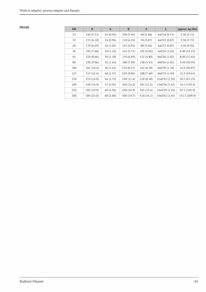
Weld-in adapter, process adapter and flanges
Endress+Hauser 45
PN100 DN D b K d L approx. kg (lbs)
25 140 (5.51) 24 (0.94) 100 (3.94) 68 (2.68) 4x18 (0.71) 2.50 (5.51)
32 155 (6.10) 24 (0.94) 110 (4.33) 78 (3.07) 4x22 (0.87) 3.50 (7.72)
40 170 (6.69) 26 (1.02) 125 (4.92) 88 (3.46) 4x22 (0.87) 4.50 (9.92)
50 195 (7.68) 28 (1.10) 145 (5.71) 102 (4.02) 4x26 (1.02) 6.00 (13.23)
65 220 (8.66) 30 (1.18) 170 (6.69) 122 (4.80) 8x26 (1.02) 8.00 (17.64)
80 230 (9.06) 32 (1.26) 180 (7.09) 138 (5.43) 8x26 (1.02) 9.50 (20.95)
100 265 (10.4) 36 (1.42) 210 (8.27) 162 (6.38) 8x30 (1.18) 14.0 (30.87)
125 315 (12.4) 40 (1.57) 250 (9.84) 188 (7.40) 8x33 (1.30) 22.5 (49.61)
150 355 (14.0) 44 (1.73) 290 (11.4) 218 (8.58) 12x33 (1.30) 30.5 (67.25)
200 430 (16.9) 52 (2.05) 360 (14.2) 285 (11.2) 12x36 (1.42) 54.5 (120.2)
250 505 (19.9) 60 (2.36) 430 (16.9) 345 (13.6) 12x39 (1.54) 87.5 (192.9)
300 585 (23.0) 68 (2.68) 500 (19.7) 410 (16.1) 16x42 (1.65) 131.5 (289.9)

Weld-in adapter, process adapter and flanges
46 Endress+Hauser
ASME-Flange (ASME B16.5-2013)
0029175
(Raised face RF)
L Diameter of holesd Raised face diameterK Diameter of hole circleD Flange diameterb Total flange thicknessf Raised face height Class 150/300: 1.6 mm (0.06 in) or
from Class 600: 6.4 mm (0.25 in)
Note!Surface finish of the gasket faces Ra 3.2 to 6.3 μm (126 to 248 μin).
Class 150 In following tables, the dimensions are indicated in mm (in) unless otherwise noted.
D
fb
Kd
L
NPS (Nominal pipe size)
D b K d L approx. kg (lbs)
1" 108.0 (4.25) 14.2 (0.56) 79.2 (3.12) 50.8 (2.00) 4x15.7(0.62) 0.86 (1.9)
1¼" 117.3 (4.62) 15.7 (0.62) 88.9 (3.50) 63.5 (2.50) 4x15.7(0.62) 1.17 (2.58)
1½" 127.0 (5.00) 17.5 (0.69) 98.6 (3.88) 73.2 (2.88) 4x15.7(0.62) 1.53 (3.37)
2" 152.4 (6.00) 19.1 (0.75) 120.7 (4.75) 91.9 (3.62) 4x19.1(0.75) 2.42 (5.34)
2½" 177.8 (7.00) 22.4 (0.88) 139.7 (5.50) 104.6 (4.12) 4x19.1(0.75) 3.94 (8.69)
3" 190.5 (7.50) 23.9 (0.94) 152.4 (6.00) 127.0 (5.00) 4x19.1(0.75) 4.93 (10.87)
3½" 215.9 (8.50) 23.9 (0.94) 177.8 (7.00) 139.7 (5.50) 8x19.1(0.75) 6.17 (13.60)
4" 228.6 (9.00) 23.9 (0.94) 190.5 (7.50) 157.2 (6.19) 8x19.1(0.75) 7.00 (15.44)
5" 254.0 (10.0) 23.9 (0.94) 215.9 (8.50) 185.7 (7.31) 8x22.4(0.88) 8.63 (19.03)
6" 279.4 (11.0) 25.4 (1.00) 241.3 (9.50) 215.9 (8.50) 8x22.4(0.88) 11.3 (24.92)
8" 342.9 (13.5) 28.4 (1.12) 298.5 (11.8) 269.7 (10.6) 8x22.4(0.88) 19.6 (43.22)
10" 406.4 (16.0) 30.2 (1.19) 362.0 (14.3) 323.8 (12.7) 12x25.4(1.00) 28.8 (63.50)

Weld-in adapter, process adapter and flanges
Endress+Hauser 47
Class 300
Class 600
NPS (Nominal pipe size)
D b K d L approx. kg (lbs)
1" 124.0 (4.88) 17.5 (0.69) 88.9 (3.50) 50.8 (2.00) 4x19.1(0.75) 1.39 (3.06)
1¼" 133.4 (5.25) 19.1 (0.75) 98.6 (3.88) 63.5 (2.50) 4x19.1(0.75) 1.79 (3.95)
1½" 155.4 (6.12) 20.6 (0.81) 114.3 (4.50) 73.2 (2.88) 4x22.4(0.88) 2.66 (5.87)
2" 165.1 (6.50) 22.4 (0.88) 127.0 (5.00) 91.9 (3.62) 8x19.1(0.75) 3.18 (7.01)
2½" 190.5 (7.50) 25.4 (1.00) 149.4 (5.88) 104.6 (4.12) 8x22.4(0.88) 4.85 (10.69)
3" 209.5 (8.25) 28.4 (1.12) 168.1 (6.62) 127.0 (5.00) 8x22.4(0.88) 6.81 (15.02)
3½" 228.6 (9.00) 30.2 (1.19) 184.2 (7.25) 139.7 (5.50) 8x22.4(0.88) 8.71 (19.21)
4" 254.0 (10.0) 31.8 (1.25) 200.2 (7.88) 157.2 (6.19) 8x22.4(0.88) 11.5 (25.36)
5" 279.4 (11.0) 35.1 (1.38) 235.0 (9.25) 185.7 (7.31) 8x22.4(0.88) 15.6 (34.4)
6" 317.5 (12.5) 36.6 (1.44) 269.7 (10.6) 215.9 (8.50) 12x22.4(0.88) 20.9 (46.08)
8" 381.0 (15.0) 41.1 (1.62) 330.2 (13.0) 269.7 (10.6) 12x25.4(1.00) 34.3 (75.63)
10" 444.5 (17.5) 47.8 (1.88) 387.4 (15.3) 323.8 (12.7) 16x28.4(1.12) 53.3 (117.5)
NPS (Nominal pipe size)
D b K d L approx. kg (lbs)
1" 124.0 (4.88) 17.5 (0.69) 88.9 (3.50) 50.8 (2.00) 4x19.1(0.75) 1.60 (3.53)
1¼" 133.4 (5.25) 20.6 (0.81) 98.6 (3.88) 63.5 (2.50) 4x19.1(0.75) 2.23 (4.92)
1½" 155.4 (6.12) 22.4 (0.88) 114.3 (4.50) 73.2 (2.88) 4x22.4(0.88) 3.25 (7.17)
2" 165.1 (6.50) 25.4 (1.00) 127.0 (5.00) 91.9 (3.62) 8x19.1(0.75) 4.15 (9.15)
2½" 190.5 (7.50) 28.4 (1.12) 149.4 (5.88) 104.6 (4.12) 8x22.4(0.88) 6.13 (13.52)
3" 209.5 (8.25) 31.8 (1.25) 168.1 (6.62) 127.0 (5.00) 8x22.4(0.88) 8.44 (18.61)
3½" 228.6 (9.00) 35.1 (1.38) 184.2 (7.25) 139.7 (5.50) 8x25.4(1.00) 11.0 (24.26)
4" 273.1 (10.8) 38.1 (1.50) 215.9 (8.50) 157.2 (6.19) 8x25.4(1.00) 17.3 (38.15)
5" 330.2 (13.0) 44.5 (1.75) 266.7 (10.5) 185.7 (7.31) 8x28.4(1.12) 29.4 (64.83)
6" 355.6 (14.0) 47.8 (1.88) 292.1 (11.5) 215.9 (8.50) 12x28.4(1.12) 36.1 (79.6)
8" 419.1 (16.5) 55.6 (2.19) 349.3 (13.8) 269.7 (10.6) 12x31.8(1.25) 58.9 (129.9)
10" 508.0 (20.0) 63.5 (2.50) 431.8 (17.0) 323.8 (12.7) 16x35.1(1.38) 97.5 (214.9)

Weld-in adapter, process adapter and flanges
48 Endress+Hauser
Class 900
Class 1500
NPS (Nominal pipe size)
D b K d L approx. kg (lbs)
1" 149.4 (5.88) 28.4 (1.12) 101.6 (4.00) 50.8 (2.00) 4x25.4(1.00) 3.57 (7.87)
1¼" 158.8 (6.25) 28.4 (1.12) 111.3 (4.38) 63.5 (2.50) 4x25.4(1.00) 4.14 (9.13)
1½" 177.8 (7.00) 31.8 (1.25) 124.0 (4.88) 73.2 (2.88) 4x28.4(1.12) 5.75 (12.68)
2" 215.9 (8.50) 38.1 (1.50) 165.1 (6.50) 91.9 (3.62) 8x25.4(1.00) 10.1 (22.27)
2½" 244.4 (9.62) 41.1 (1.62) 190.5 (7.50) 104.6 (4.12) 8x28.4(1.12) 14.0 (30.87)
3" 241.3 (9.50) 38.1 (1.50) 190.5 (7.50) 127.0 (5.00) 8x25.4(1.00) 13.1 (28.89)
4" 292.1 (11.50) 44.5 (1.75) 235.0 (9.25) 157.2 (6.19) 8x31.8(1.25) 26.9 (59.31)
5" 349.3 (13.8) 50.8 (2.00) 279.4 (11.0) 185.7 (7.31) 8x35.1(1.38) 36.5 (80.48)
6" 381.0 (15.00) 55.6 (2.19) 317.5 (12.5) 215.9 (8.50) 12x31.8(1.25) 47.4 (104.5)
8" 469.9 (18.50) 63.5 (2.50) 393.7 (15.5) 269.7 (10.6) 12x38.1(1.50) 82.5 (181.9)
10" 546.1 (21.50) 69.9 (2.75) 469.9 (18.5) 323.8 (12.7) 16x38.1(1.50) 122 (269.0)
NPS (Nominal pipe size)
D b K d L approx. kg (lbs)
1" 149.4 (5.88) 28.4 (1.12) 101.6 (4.00) 50.8 (2.00) 4x25.4(1.00) 3.57 (7.87)
1¼" 158.8 (6.25) 28.4 (1.12) 111.3 (4.38) 63.5 (2.50) 4x25.4(1.00) 4.14 (9.13)
1½" 177.8 (7.00) 31.8 (1.25) 124.0 (4.88) 73.2 (2.88) 4x28.4(1.12) 5.75 (12.68)
2" 215.9 (8.50) 38.1 (1.50) 165.1 (6.50) 91.9 (3.62) 8x25.4(1.00) 10.1 (22.27)
2½" 244.4 (9.62) 41.1 (1.62) 190.5 (7.50) 104.6 (4.12) 8x28.4(1.12) 14.0 (30.87)
3" 266.7 (10.50) 47.8 (1.88) 203.2 (8.00) 127.0 (5.00) 8x31.8(1.25) 19.1 (42.12)
4" 311.2 (12.3) 53.8 (2.12) 241.3 (9.50) 157.2 (6.19) 8x35.1(1.38) 29.9 (65.93)
5" 374.7 (14.8) 73.2 (2.88) 292.1 (11.5) 185.7 (7.31) 8x41.1(1.62) 58.4 (128.8)
6" 393.7 (15.50) 82.6 (3.25) 317.5 (12.5) 215.9 (8.50) 12x38.1(1.50) 71.8 (158.3)
8" 482.6 (19.00) 91.9 (3.62) 393.7 (15.5) 269.7 (10.6) 12x44.5(1.75) 122 (269.0)
10" 584.2 (23.00) 108.0 (4.25) 482.6 (19.0) 323.8 (12.7) 12x50.8(2.00) 210 (463.0)

Weld-in adapter, process adapter and flanges
Endress+Hauser 49
JIS flanges (B 2220)
A0029174
(Raised face RF)
L Diameter of holesd Raised face diameterK Diameter of hole circleD Flange diameterb Total flange thicknessf Raised face height (general 2 mm (0.08 in))
Note!Surface finish of the gasket faces Ra 3.2 to 6.3 μm (126 to 248 μin).
10 K In following tables, the dimensions are indicated in mm (in) unless otherwise noted.
20 K
L
d
D
K
fb
DN D b K d L
25 125 (4.92) 14 (0.55) 90 (3.54) 67 (2.64) 4x19 (0.75)
32 135 (5.31) 16 (0.63) 100 (3.94) 76 (2.99) 4x19 (0.75)
40 140 (5.51) 16 (0.63) 105 (4.13) 81 (3.19) 4x19 (0.75)
50 155 (6.10) 16 (0.63) 120 (4.72) 96 (3.78) 4x19 (0.75)
65 175 (6.89) 18 (0.71) 140 (5.51) 116 (4.57) 4x19 (0.75)
80 185 (7.28) 18 (0.71) 150 (5.91) 126 (4.96) 8x19 (0.75)
100 210 (8.27) 18 (0.71) 175 (6.89) 151 (5.94) 8x19 (0.75)
125 250 (9.84) 20 (0.79) 210 (8.27) 182 (7.17) 8x23 (0.91)
150 280 (11.0) 22 (0.87) 240 (9.45) 212 (8.35) 8x23 (0.91)
200 330 (13.0) 22 (0.87) 290 (11.4) 262 (10.3) 12x23 (0.91)
250 400 (15.7) 24 (0.94) 355 (14.0) 324 (12.8) 12x25 (0.98)
300 445 (17.5) 24 (0.94) 400 (15.7) 368 (14.5) 16x25 (0.98)
DN D b K d L
25 125 (4.92) 16 (0.63) 90 (3.54) 67 (2.64) 4x19 (0.75)
32 135 (5.31) 18 (0.71) 100 (3.94) 76 (2.99) 4x19 (0.75)
40 140 (5.51) 18 (0.71) 105 (4.13) 81 (3.19) 4x19 (0.75)
50 155 (6.10) 18 (0.71) 120 (4.72) 96 (3.78) 8x19 (0.75)
65 175 (6.89) 20 (0.79) 140 (5.51) 116 (4.57) 8x19 (0.75)
80 200 (7.87) 22 (0.87) 160 (6.30) 132 (5.20) 8x23 (0.91)
100 225 (8.86) 24 (0.94) 185 (7.28) 160 (6.30) 8x23 (0.91)
125 270 (10.6) 26 (1.02) 225 (8.86) 195 (7.68) 8x25 (0.98)
150 305 (12.0) 28 (1.10) 260 (10.2) 230 (9.06) 12x25 (0.98)
200 350 (13.8) 30 (1.18) 305 (12.0) 275 (10.8) 12x25 (0.98)
250 430 (16.9) 34 (1.34) 380 (15.0) 345 (13.6) 12x27 (1.06)
300 480 (18.9) 36 (1.42) 430 (16.9) 395 (15.6) 16x27 (1.06)

Weld-in adapter, process adapter and flanges
50 Endress+Hauser
63 K DN D b K d L
25 140 (5.51) 27 (1.06) 100 (3.94) 70 (2.76) 4x23 (0.91)
32 150 (5.91) 30 (1.18) 110 (4.33) 80 (3.15) 4x23 (0.91)
40 175 (6.89) 32 (1.26) 130 (5.12) 90 (3.54) 4x25 (0.98)
50 185 (7.28) 34 (1.34) 145 (5.71) 105 (4.13) 8x23 (0.91)
65 220 (8.66) 38 (1.50) 175 (6.89) 130 (5.12) 8x25 (0.98)
80 230 (9.06) 40 (1.57) 185 (7.28) 140 (5.51) 8x25 (0.98)
100 270 (10.6) 44 (1.73) 220 (8.66) 165 (6.50) 8x27 (1.06)
125 325 (12.8) 50 (1.97) 265 (10.4) 200 (7.87) 8x33 (1.30)
150 365 (14.4) 54 (2.13) 305 (12.0) 240 (9.45) 12x33 (1.30)
200 425 (16.7) 60 (2.36) 360 (14.2) 290 (11.4) 12x33 (1.30)
250 500 (19.7) 68 (2.68) 430 (16.9) 355 (14.0) 12x39 (1.54)
300 560 (22.0) 77 (3.03) 485 (19.1) 410 (16.1) 16x39 (1.54)

Weld-in adapter, process adapter and flanges
Endress+Hauser 51
Pressure-temperature dependencies
EN flanges1)
ASME flanges)
JIS flanges)
1) With regard to their stability-temperature property, the materials 1.4435 and 1.4404 are grouped in DIN EN 1092-1 table 18 under 13E0 and in JIS B2220:2004 table 5 under 023b. The ASME flanges are dual rated flanges (316/316L) and grouped in table 2-2.2 according to ASME B16.5-2013.
Temperature range
Nominal pressure bar (psi)
PN16 PN25 PN40 PN63 PN100
10 °C ... +50 °C (+14 °F ... +122 °F) 16.0 (232) 25.0 (362) 40.0 (580) 63.0 (913) 100.0 (1450)
50 °C (122 °F) 15.5 (225) 24.3 (352) 38.9 (564) 61.3 (889) 97.3 (1411)
100 °C (212 °F) 15.1 (219) 23.6 (342) 37.9 (550) 59.7 (866) 94.7 (1373)
150 °C (302 °F) 13.7 (199) 21.5 (312) 34.4 (499) 54.3 (787) 86.1 (1248)
200 °C (392 °F) 12.7 (184) 19.8 (287) 31.8 (461) 50.1 (726) 79.5 (1153)
250 °C (482 °F) 11.9 (173) 18.6 (270) 29.9 (434) 47.1 (683) 74.7 (1083)
300 °C (572 °F) 11.0 (159) 17.2 (249) 27.6 (400) 43.5 (631) 69.0 (1000)
350 °C (662 °F) 10.5 (152) 16.5 (239) 26.4 (383) 41.7 (605) 66.1 (958)
400 °C (752 °F) 10.2 (148) 16.0 (232) 25.7 (373) 40.1 (580) 64.2 (931)
Temperature range
Nominal pressure bar (psi)
Class 150 Class 300 Class 600 Class 900 Class 1500
29 °C ... +38 °C 20 °F ... +100 °F)
19.0 (275) 49.6 (719) 99.3 (1440) 148.9 (2159) 248.2 (3599)
50 °C (122 °F) 18.4 (267) 48.1 (697) 96.2 (1395) 144.3 (2092) 240.6 (3489)
100 °C (212 °F) 16.2 (235) 42.2 (612) 84.4 (1224) 126.6 (1836) 211.0 (3059)
150 °C (302 °F) 14.8 (215) 38.5 (558) 77.0 (1116) 115.5 (1675) 192.5 (2791)
200 °C (392 °F) 13.7 (199) 35.7 (518) 71.3 (1034) 107.0 (1551) 178.3 (2588)
250 °C (482 °F) 12.1 (175) 33.4 (484) 66.8 (969) 100.1 (1451) 166.9 (2420)
300 °C (572 °F) 10.2 (148) 31.6 (458) 63.2 (916) 94.9 (1376) 158.1 (2292)
325 °C (617 °F) 9.3 (135) 30.9 (448) 61.8 (896) 92.7 (1344) 154.4 (2239)
350 °C (662 °F) 8.4 (122) 30.3 (439) 60.7 (880) 91.0 (1319) 151.6 (2189)
375 °C (707 °F) 7.4 (107) 29.9 (434) 59.8 (867) 89.6 (1299) 149.4 (2166)
400 °C (752 °F) 6.5 (94) 29.4 (426) 58.9 (854) 88.3 (1280) 147.2 (2134)
Temperature range
Nominal pressure bar (psi)
10 K 20 K
for all flanges to DN 125 from DN 150 up to DN 250
DN 300
up to 120 °C (248 °F) 14 (203.0) 34 (493.0) 20 (290.0) 20 (290.0)
220 °C (428 °F) 12 (174.0) 31 (449.5) 20 (290.0) –
300 °C (572 °F) 10 (145.0) 29 (420.5) 19 (275.5) –
350 °C (662 °F) – 26 (377.0) 17 (246.5) –
400 °C (752 °F) – 23 (333.5) 17 (246.5) –
425 °C (797 °F) – 20 (290.0) 17 (246.5) –

Weld-in adapter, process adapter and flanges
52 Endress+Hauser
Adapter flange FAU70An adapter flange makes it possible to use devices with a threaded connection.
A0029173
1 Adapter flange2 Nozzle3 Probe
FAU70E Version with metrical thread
Order information
The versions entered make up the order code:
FAU70A Version with conical thread
The versions entered make up the order code:
1
3 2
010 Process Connection12 DN 50 PN16 A, flange EN 1092-1 (DIN 2527 B)14 DN 80 PN16 A, flange EN 1092-1 (DIN 2527 B)15 DN 100 PN16 A, flange EN 1092-1 (DIN 2527 B)99 Special version, to be specified
020 Sensor Connection3 Thread ISO228 G1-1/24 Thread ISO228 G299 Special version, to be specified
030 Flange Material2 316L3 Steel7 Polypropylene99 Special version, to be specified
010 020 030FAU70E -
010 Process Connection22 2" 150 lbs FF, flange ANSI B16.524 3" 150 lbs FF, flange ANSI B16.525 4" 150 lbs FF, flange ANSI B16.599 Special version, to be specified
020 Sensor Connection5 Thread NPT1-1/26 Thread NPT299 Special version, to be specified
030 Flange Material2 316L3 Steel7 Polypropylene99 Special version, to be specified
010 020 030FAU70A -

Weld-in adapter, process adapter and flanges
Endress+Hauser 53
Slip-on flange FAU80The sensors (FDU91F, FDU80F, FDU81F) can be flush mounted using a FAU80 slip-on flange. Flanges in polypropylene (PP) should only used with pressures up to 1.5 barabs (22 psi) flanges in 316L also above.
A0029186
Details to dimension "Mechanical Construction" ä 39
FAU80 Version slip-on flange Order information
The versions entered make up the order code:
D
K
L
b
010 Process ConnectionAA 3" 150 lbs FF, flange ANSI B16.5AH 4" 150 lbs FF, flange ANSI B16.5CA DN 80 PN16 A, flange EN1092-1 (DIN2527 B)CH DN 100 PN16 A, flange EN1092-1 (DIN2527 B)KA 10K 80A FF, flange JIS B2220KH 10K 100A FF, flange JIS B2220YY Special version, to be specified
020 Flange MaterialJ 316LP PPs, max. 1.5 bar absY Special version, to be specified
010 020FAU80 -

Weld-in adapter, process adapter and flanges
54 Endress+Hauser
Screw in flange FAX50The screw in flange is an universal flange. On the basis of dimensions min./max. it can be used for all three standards (DIN - ASME - JIS).
FAX50 universal flange DIN-ASME-JIS
A0029185
L Diameter of holesK1, K2 Diameter of hole circleD Flange diameterb Total flange thicknessB Slotted hole (width)
G ¾", NPT ¾" In following tables, the dimensions are indicated in mm (in) unless otherwise noted.
G 1", NPT 1"
Exception G 1"
D
b
K1
L
B
K2
DN D b L K1 K2 approx. kg (lbs)
PP PVDF 316L
50 165 (6.50)
20 (0.79)
4x19(0.75)
120 (4.72) 125 (4.92) – – 3.11 (6.86)
80 200 (7.87) 8x19(0.75)
150 (5.91) 160 (6.30) – – 4.37 (9.64)
100 228.6 (9.0) 8x19(0.75)
175 (6.89) 190.5 (7.5) – – 5.79 (12.77)
DN D b L K1 K2 approx. kg (lbs)
PP PVDF 316L
80 200 (7.87)
20 (0.79)
8x19(0.75)
150 (5.91) 160 (6.30) 0.50 (1.10)
0.97 (2.14)
4.34 (9.57)
100 228.6 (9.0) 8x19(0.75)
175 (6.89) 190.5 (7.5) 0.66 (1.46)
1.29 (2.84)
5.75 (12.68)
150 285 (11.2) 8x23(0.91)
240 (9.45) 241.3 (9.5) 1.09 (2.40)
2.12 (4.67)
9.44 (20.82)
200 1)
1) Only for DIN und JIS!
340 (13.4) 12x23(0.91)
290 (11.4) 295 (11.6) 1.53 (3.37)
– –
250 406.4 (16.0) 12x26(1.02)
355 (14.0) 362 (14.3) 2.20 (4.85)
– –
NPS (Nomi-nal pipe
size)
D b L K1 K2 approx. kg (lbs)
ASME PP PVDF 316L
8" 342.9 (13.5)
20 (0.79)
8x22.5 (0.89)
298.5 (11.8)
298.5 (11.8)
1.61 (3.55)
– –

Weld-in adapter, process adapter and flanges
Endress+Hauser 55
G 1½", NPT 1½"
G 2", NPT 2"
DN D b L K1 K2 approx. kg (lbs)
PP PVDF 316L
50 165 (6.50)
20 (0.79)
4x19(0.75)
120 (4.72) 125 (4.92) 0.34(0.75)
0.67(1.48)
2.97 (6.55)
80 200 (7.87) 8x19(0.75)
150 (5.91) 160 (6.30) 0.49(1.08)
0.95(2.09)
4.24 (9.35)
100 228.6 (9.0) 8x19(0.75)
175 (6.89) 190.5 (7.5) 0.65(1.43)
1.27(2.80)
5.65 (12.46)
150 285 (11.2) 8x23(0.91)
240 (9.45) 241.3 (9.5) 1.08(2.38)
2.09(4.61)
9.34(20.59)
DN D b L K1 K2 approx. kg (lbs)
PP PVDF 316L
50 165 (6.50)
20 (0.79)
4x19(0.75)
120 (4.72) 125 (4.92) 0.33 (0.73)
0.63 (1.39)
2.83 (6.24)
80 200 (7.87) 8x19(0.75)
150 (5.91) 160 (6.30) 0.47 (1.04)
0.92 (2.03)
4.10 (9.04)
100 228.6 (9.0) 8x19(0.75)
175 (6.89) 190.5 (7.5) 0.64 (1.41)
1.24 (2.73)
5.51 (12.15)
150 285 (11.2) 8x23(0.91)
240 (9.45) 241.3 (9.5) 1.06 (2.34)
2.06 (4.54)
9.20 (20.29)

Weld-in adapter, process adapter and flanges
56 Endress+Hauser
Order information FAX50
The versions entered make up the order code:
015 Material:BR1 DN50 PN10/16 A, steel flange EN1092-1BS1 DN80 PN10/16 A, steel flange EN1092-1BT1 DN100 PN10/16 A, steel flange EN1092-1JF1 2" 150lbs FF, steel flange ANSI B16.5JG1 3" 150lbs FF, steel flange ANSI B16.5JH1 4" 150lbs FF, steel flange ANSI B16.5JK2 8" 150lbs FF, PP max 3 bar abs/44 psia flange ANSI B16.5XIF UNI flange 2"/DN50/50, PVDF max 4 bar abs/58 psia, suitable for 2" 150 lbs/DN50 PN16/10K 50XIG UNI flange 2"/DN50/50, PP max 4 bar abs/58 psia, suitable for 2" 150 lbs/DN50 PN16/10K 50XIJ UNI flange 2"/DN50/50, 316L max 4 bar abs/58 psia, suitable for 2" 150 lbs/DN50 PN16/10K 50XJF UNI flange 3"/DN80/80, PVDF max 4 bar abs/58 psia, suitable for 3" 150 lbs/DN80 PN16/10K 80XJG UNI flange 3"/DN80/80, PP max 4 bar abs/58 psia, suitable for 3" 150 lbs/DN80 PN16/10K 80XJJ UNI flange 3"/DN80/80, 316L max 4 bar abs/58 psia, suitable for 3" 150 lbs/DN80 PN16/10K 80XKF UNI flange 4"/DN100/100, PVDF max 4 bar abs/58 psia, suitable for 4" 150 lbs/DN100 PN16/10K 100XKG UNI flange 4"/DN100/100, PP max 4 bar abs/58 psia, suitable for 4" 150 lbs/DN100 PN16/10K 100XKJ UNI flange 4"/DN100/100, 316L max 4 bar abs/58 psia, suitable for 4" 150 lbs/DN100 PN16/10K 100XLF UNI flange 6"/DN150/150, PVDF max 4 bar abs/58 psia, suitable for 6" 150 lbs/DN150 PN16/10K 150XLG UNI flange 6"/DN150/150, PP max 4 bar abs/58 psia, suitable for 6" 150 lbs/DN150 PN16/10K 150XLJ UNI flange 6"/DN150/150, 316L max 4 bar abs/58 psia, suitable for 6" 150 lbs/DN150 PN16/10K 150XMG UNI flange DN200/200, PP max 4 bar abs/58 psia, suitable for DN200 PN16/10K 200XNG UNI flange DN250/250, PP max 4 bar abs/58 psia, suitable for DN250 PN16/10K 250YYY Special version
020 Sensor Connection:A Thread ISO228 G3/4B Thread ISO228 G1C Thread ISO228 G1-1/2D Thread ISO228 G2E Thread ANSI NPT3/4F Thread ANSI NPT1G Thread ANSI NPT1-1/2H Thread ANSI NPT2Y Special version
15 20FAX50 -

Weld-in adapter, process adapter and flanges
Endress+Hauser 57

58

59

www.addresses.endress.com
71375968
Related Documents