HAL Id: hal-01255020 https://hal.archives-ouvertes.fr/hal-01255020 Submitted on 11 Feb 2016 HAL is a multi-disciplinary open access archive for the deposit and dissemination of sci- entific research documents, whether they are pub- lished or not. The documents may come from teaching and research institutions in France or abroad, or from public or private research centers. L’archive ouverte pluridisciplinaire HAL, est destinée au dépôt et à la diffusion de documents scientifiques de niveau recherche, publiés ou non, émanant des établissements d’enseignement et de recherche français ou étrangers, des laboratoires publics ou privés. Adaptability of parabolic wave equation and Gaussian Beam Shooting methods to electromagnetic propagation in urban configurations Arnaud Ginestet, Christine Letrou, Gilles Beauquet, Emna-Amira Fnaiech To cite this version: Arnaud Ginestet, Christine Letrou, Gilles Beauquet, Emna-Amira Fnaiech. Adaptability of parabolic wave equation and Gaussian Beam Shooting methods to electromagnetic propagation in urban con- figurations. RADAR 2014 : International Radar Conference, Oct 2014, Lille, France. pp.1 - 6, 10.1109/RADAR.2014.7060263. hal-01255020

Welcome message from author
This document is posted to help you gain knowledge. Please leave a comment to let me know what you think about it! Share it to your friends and learn new things together.
Transcript

HAL Id: hal-01255020https://hal.archives-ouvertes.fr/hal-01255020
Submitted on 11 Feb 2016
HAL is a multi-disciplinary open accessarchive for the deposit and dissemination of sci-entific research documents, whether they are pub-lished or not. The documents may come fromteaching and research institutions in France orabroad, or from public or private research centers.
L’archive ouverte pluridisciplinaire HAL, estdestinée au dépôt et à la diffusion de documentsscientifiques de niveau recherche, publiés ou non,émanant des établissements d’enseignement et derecherche français ou étrangers, des laboratoirespublics ou privés.
Adaptability of parabolic wave equation and GaussianBeam Shooting methods to electromagnetic propagation
in urban configurationsArnaud Ginestet, Christine Letrou, Gilles Beauquet, Emna-Amira Fnaiech
To cite this version:Arnaud Ginestet, Christine Letrou, Gilles Beauquet, Emna-Amira Fnaiech. Adaptability of parabolicwave equation and Gaussian Beam Shooting methods to electromagnetic propagation in urban con-figurations. RADAR 2014 : International Radar Conference, Oct 2014, Lille, France. pp.1 - 6,�10.1109/RADAR.2014.7060263�. �hal-01255020�
Adaptability of Parabolic Wave Equation andGaussian Beam Shooting methods to
Electromagnetic Propagation in UrbanConfigurations
Arnaud Ginestet∗, Christine Letrou†, Gilles Beauquet‡and Emna-Amira Fnaiech†∗NOVELTIS
153 rue du Lac, 31670 Labege, FranceEmail: [email protected]†SAMOVAR (UMR CNRS 5157)
Institut TELECOM SudParis9 rue Charles Fournier, 91011 Evry Cedex, France
‡THALES Air Systems S.A.Hameau de Roussigny, 91470 Limours, France
Abstract—In spite of well-known limitations, ray based meth-ods are the quasi-unique tool for modelling the electromagneticpropagation in urban areas. As an alternative to these methods,two models based on the resolution of the Parabolic WaveEquation, and on Gaussian Beam Shooting, are proposed. Bothare specifically adapted to meet the challenges of urban areaspropagation: three-dimensional, wide angle approximation andconsidering the backscatter propagation for the first one; takinginto account ground and grazing angles for the second one. Apreliminary test case is presented and configurations of interestunder processing are detailed.
I. INTRODUCTION
A. Context
The knowledge of electromagnetic propagation is critical toincrease the efficiency and need for control of communicationsystems. It improves detection and discrimination capabilitiesof radar systems in presence of dense obstacles.
Nowadays cities become a major configuration, since forthe first time in the history of mankind the urban populationoutnumbered rural population in 2007. More, this ratio isexpected to reach 60 % by 2030. This change has to be takeninto account by the scientific community, regardless of theirspeciality.
Indeed, the presence of obstructing buildings in an urbanareas causes shadowing of the emitter from the receiver andcan lead to severe loss of signals. Thus, electromagneticpropagation models need to be adapted to the specific urbanconfigurations, as far as three-dimensional processing becomesmandatory.
B. Configurations of interest
When dealing with electromagnetic propagation, configu-rations of interest will support the efficiency assessment ofmodelling tools regarding two objectives:
1) Analysis of urban areas and semi-urban areas as elec-tromagnetic scenes;
2) Production of enough results to help the deployment ofa system (radar or stations).
The interest lies in the theoretical forecast of performancesas close as possible to reality: it concerns attenuation betweenBase Station (BS) and User Equipment (UE) for broadbandmobile or it concerns complete monitoring of radar detectionloss due to obstacles in civil, military or security domains.
Masking and multiple reflections must be taken into ac-count in three-dimensional electromagnetic scenes. Elemen-tary mechanisms in play could be:
• Obstruction due to erected obstacle(s) close to the emit-ting antenna or close to the receiving antenna;
• Lateral deviation on large distant walls;• Influence of relief (at a large scale): beam is guided in a
turning valley or dispersed around a hill.
Configurations of interest can be illustrated in the twofollowing cases.
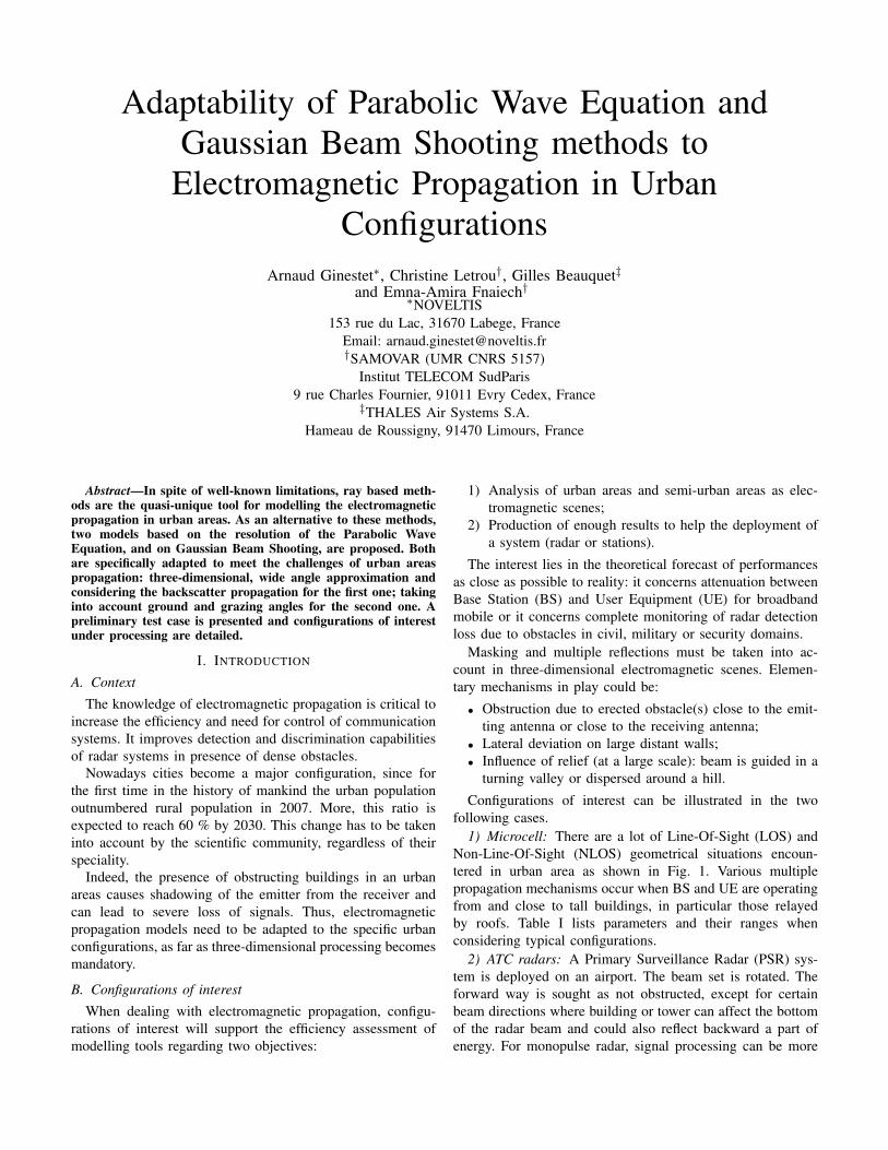
1) Microcell: There are a lot of Line-Of-Sight (LOS) andNon-Line-Of-Sight (NLOS) geometrical situations encoun-tered in urban area as shown in Fig. 1. Various multiplepropagation mechanisms occur when BS and UE are operatingfrom and close to tall buildings, in particular those relayedby roofs. Table I lists parameters and their ranges whenconsidering typical configurations.
2) ATC radars: A Primary Surveillance Radar (PSR) sys-tem is deployed on an airport. The beam set is rotated. Theforward way is sought as not obstructed, except for certainbeam directions where building or tower can affect the bottomof the radar beam and could also reflect backward a part ofenergy. For monopulse radar, signal processing can be more
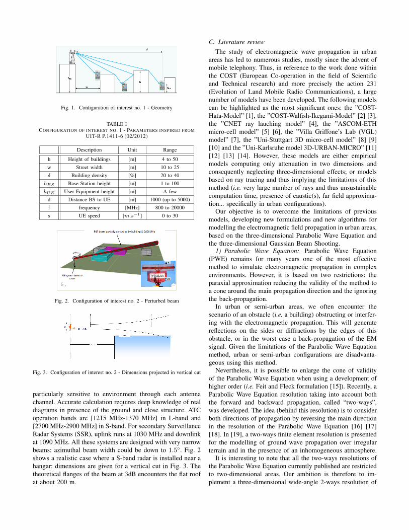
Fig. 1. Configuration of interest no. 1 - Geometry
TABLE ICONFIGURATION OF INTEREST NO. 1 - PARAMETERS INSPIRED FROM
UIT-R P.1411-6 (02/2012)
Description Unit Range
h Height of buildings [m] 4 to 50
w Street width [m] 10 to 25
δ Building density [%] 20 to 40
hBS Base Station height [m] 1 to 100
hUE User Equipment height [m] A few
d Distance BS to UE [m] 1000 (up to 5000)
f frequency [MHz] 800 to 20000
s UE speed [m.s−1] 0 to 30
Fig. 2. Configuration of interest no. 2 - Perturbed beam
Fig. 3. Configuration of interest no. 2 - Dimensions projected in vertical cut
particularly sensitive to environment through each antennachannel. Accurate calculation requires deep knowledge of realdiagrams in presence of the ground and close structure. ATCoperation bands are [1215 MHz-1370 MHz] in L-band and[2700 MHz-2900 MHz] in S-band. For secondary SurveillanceRadar Systems (SSR), uplink runs at 1030 MHz and downlinkat 1090 MHz. All these systems are designed with very narrowbeams: azimuthal beam width could be down to 1.5◦. Fig. 2shows a realistic case where a S-band radar is installed near ahangar: dimensions are given for a vertical cut in Fig. 3. Thetheoretical flanges of the beam at 3dB encounters the flat roofat about 200 m.
C. Literature reviewThe study of electromagnetic wave propagation in urban
areas has led to numerous studies, mostly since the advent ofmobile telephony. Thus, in reference to the work done withinthe COST (European Co-operation in the field of Scientificand Technical research) and more precisely the action 231(Evolution of Land Mobile Radio Communications), a largenumber of models have been developed. The following modelscan be highlighted as the most significant ones: the ”COST-Hata-Model” [1], the ”COST-Walfish-Ikegami-Model” [2] [3],the ”CNET ray lauching model” [4], the ”ASCOM-ETHmicro-cell model” [5] [6], the ”Villa Griffone’s Lab (VGL)model” [7], the ”Uni-Stuttgart 3D micro-cell model” [8] [9][10] and the ”Uni-Karlsruhe model 3D-URBAN-MICRO” [11][12] [13] [14]. However, these models are either empiricalmodels computing only attenuation in two dimensions andconsequently neglecting three-dimensional effects; or modelsbased on ray tracing and thus implying the limitations of thismethod (i.e. very large number of rays and thus unsustainablecomputation time, presence of caustic(s), far field approxima-tion... specifically in urban configurations).
Our objective is to overcome the limitations of previousmodels, developing new formulations and new algorithms formodelling the electromagnetic field propagation in urban areas,based on the three-dimensional Parabolic Wave Equation andthe three-dimensional Gaussian Beam Shooting.
1) Parabolic Wave Equation: Parabolic Wave Equation(PWE) remains for many years one of the most effectivemethod to simulate electromagnetic propagation in complexenvironments. However, it is based on two restrictions: theparaxial approximation reducing the validity of the method toa cone around the main propagation direction and the ignoringthe back-propagation.
In urban or semi-urban areas, we often encounter thescenario of an obstacle (i.e. a building) obstructing or interfer-ing with the electromagnetic propagation. This will generatereflections on the sides or diffractions by the edges of thisobstacle, or in the worst case a back-propagation of the EMsignal. Given the limitations of the Parabolic Wave Equationmethod, urban or semi-urban configurations are disadvanta-geous using this method.
Nevertheless, it is possible to enlarge the cone of validityof the Parabolic Wave Equation when using a development ofhigher order (i.e. Feit and Fleck formulation [15]). Recently, aParabolic Wave Equation resolution taking into account boththe forward and backward propagation, called “two-ways”,was developed. The idea (behind this resolution) is to considerboth directions of propagation by reversing the main directionin the resolution of the Parabolic Wave Equation [16] [17][18]. In [19], a two-ways finite element resolution is presentedfor the modelling of ground wave propagation over irregularterrain and in the presence of an inhomogeneous atmosphere.
It is interesting to note that all the two-ways resolutions ofthe Parabolic Wave Equation currently published are restrictedto two-dimensional areas. Our ambition is therefore to im-plement a three-dimensional wide-angle 2-ways resolution of

the Parabolic Wave Equation in order to overcome its currentlimitations and to make it adapted to urban configurations.
2) Gaussian Beam Shooting: Although the Gaussian BeamShooting (GBS) method is particularly well suited to 3Dfield simulations in multi-reflecting contexts, few works arecurrently devoted to the use of Gaussian Beams (GB) to modelelectromagnetic propagation in urban or semi-urban areas.
In the millimetric range, ”simple” versions of GaussianBeam Shooting have provided results equivalent to that ob-tained by ray tracing techniques. In these ”simple” algorithms,no specific formulation is developed to account for diffraction.If a beam axis is incident on an obstacle, the beam isconsidered as if incident on an infinite surface. Conversely,if the beam axis does not intercept the obstacle, the beam isconsidered as if propagating in free space. This methodologywas validated by measurements around 60 GHz in indoorenvironments [20] [23]. An ultra-wide band version of thiskind of methodology has been implemented for building areasat non-millimetre frequencies, but to our knowledge resultvalidation has not been published [26].
More accurate simulations of diffracted fields, yet keepingtheir representation as a sum of Gaussian beams (formula-tions sometimes called ”B2B”, beam to beam), is howevera prerequisite for an efficient use of Gaussian Beam Shoot-ing in multipath propagation environments at frequencies ofconventional communication systems or radar systems. Asmentioned above, only few recent studies have focused onthis problem, and the resulting formulations depend on themethod used to represent the radiated or scattered fields asdiscrete sums of Gaussian beams: empirical sampling andnormalisation at arrival [25], empirical sampling in the angulardomain and frame decomposition along the edge [27], framedecomposition and frame based truncation of fields on obstaclesurface [21] [22] [24]. The latter approach is used in this workand yields Physical Optics like representation of diffractedfields.
II. FORMULATION
A. Parabolic Wave Equation
The vectorial wave function Ψ (x, y, z) can be obtainedas the solution of the following three-dimensional Helmholtzequation:{
∂2
∂x2+
∂2
∂y2+
∂2
∂z2+ k2
0n2 (x, y, z)
}Ψ (x, y, z) = 0 (1)
Where n (x, y, z) is the refractive index, k0 = 2π/λ is thefree space wavenumber (λ is the wavelength), and x, y andz are the longitudinal (range), the transverse and the heightcoordinates, respectively. Ψ (x, y, z) corresponds to either theelectric and magnetic field components for horizontal andvertical polarizations.
Considering that the direction of wave propagation is pre-dominantly along the +x-axis paraxial direction, the ParabolicWave Equation is written by separating rapidly varying phaseterms (Ψ (x, y, z) = exp (ik0x)u (x, y, z)). That is, the
Parabolic Wave Equation in terms of the slowly varyingamplitude function u (x, y, z) is expressed as follows:{
∂
∂x+ ik0
(1−√
1 + T)}{ ∂
∂x+ ik0
(1 +√
1 + T)}
u (x, y, z) = 0 (2)
Where T = k−20
(∂2/∂y2 + ∂2/∂z2
)+ n2 − 1.
The first and second parts of (2) correspond to the forwardand backward propagation waves, respectively. If the backwardpropagation is ignored (2) reduces to:{
A0∂
∂x+ A1
∂
∂x
(∂2
∂y2+
∂2
∂z2
)+ A2 +A3
(∂2
∂y2+
∂2
∂z2
)}= 0 (3)
with the help of√
1 + T ≈ (a0 + a1t) / (b0 + b1t) ap-proximation; therefore, A0 = b0 + b1
(n2 − 1
), A1 =
b1k−20 , A2 = ik0
((b0 − a0) + (b1 − a1)
(n2 − 1
)), and A3 =
ik−10 (b1− a1).If the angle of propagation measured from paraxial direction
is less than 15◦, the standard Parabolic Wave Equation isobtained with the help of square root approximation
√1 + t ≈
1 + t/2. If the propagation angle is more than 15◦, theClaerbout equation is obtained by using the first-order Padeapproximation
√1 + t ≈ (1 + 0.75t) / (1 + 0.25t) to satisfy
propagation angles up to 40◦. Thus, the contribution of a wide-angle resolution can be investigated.
A Finite-Difference methodology is then adopted in orderto “introduce” the Leontovich boundaries condition into thepropagation algorithm.
A comparison between the mixed-implicit scheme and analternating method will be performed and the contribution ofa 2-ways resolution will be quantified.
B. Gaussian Beam Shooting
In Gaussian Beam Shooting (GBS) algorithms, propagatedfields are represented as a superposition of Gaussian beams(GB) launched from the emitting antenna and transformedthrough successive interactions with obstacles. The formula-tion developed in this work is based on frame decompositionof source fields:
• The planar distribution of source fields is expressed asa weighted sum of Gaussian windows which form a”frame”.
• Each Gaussian window radiates in the form of a Gaussianbeam.
1) Frame of Gaussian windows: The frame windowsψµ(y, z) used to describe a planar source distribution in theyOz plane are constructed as the product of frame windowsψy
m,n(y) and ψzp,q(z) in L2(R):
ψµ(y, z) = ψy
m,n(y)ψz
p,q(z) (4)
where µ = (m,n, p, q) is a composite translation index in Z4.The frame windows ψy
m,n(y) are obtained by translation of

a Gaussian function ψ(y) along the spatial coordinate y andalong its spectral counterpart ky:
ψy
m,n(y) = ψ(y −my)einkyy (5)
• y and ky are respectively the spatial and spectral trans-lation steps, m and n the spatial and spectral translationindices.
• {ψµ, µ ∈ Z2} is a frame if and only if yky = 2πν, withν < 1 (ν: oversampling factor).
• the favorite choice for the translation steps is: y =√νL,
ky =√ν(2π/L) (”balanced” frame).
The same construction is used for the frame along z, with p,q the spatial and translation indices along z. In the following,the Gaussian function ψ is taken as:
ψ(y) =(√
2/L) 1
2e−π( y
L )2
(6)
2) Frame window radiation: Through paraxial asymptoticevaluation of plane wave spectrum integrals, the fields radiatedby the source field distributions ψµ(y, z) (either for y or zcomponent) are put in the form of paraxial Gaussian beams.Let us denote Bµ(r) the field radiated at point r. The paraxialexpression of Bµ is:
Bµ(r)=B0
√detΓ−1(0)
detΓ−1(xµ)exp ik
[xµ + 1
2ytµΓ(xµ)yµ
](7)
with B0 a vector depending on the source polarization. Thisexpression is analog to that of a geometrical optics rayalong the xµ direction, with Γ the curvature matrix and√
detΓ−1(0)detΓ−1(xµ)
the divergence factor. yµ = (yµ, zµ) is theposition vector of the point r in a plane transverse to thexµ axis.
The difference between geometrical optics rays andGaussian beams comes from the fact that Γ is a real matrix inthe first case, a complex one in the latter. This complex matrixaccounts for the Gaussian decay of fields with increasingdistance from the xµ axis in transverse planes. The xµ axisis then called the beam axis.
3) Gaussian beam tracking in a built environment: In thepresence of “infinite” smooth interfaces described either asdielectric interfaces or by surface impedance models, GBcan be tracked in a way similar to rays, thanks to theirparaxial properties. In the case of planar interfaces, reflected orrefracted beams can even be expressed as beams originating in“image” source distributions. The presence of ground is easilyaccounted for in this way. Yet, paraxial beam tracking cannotaddress problems where beams impinge on discontinuities, asshown in Fig. 4. Specific B2B algorithms are thus developedto simulate propagation in the presence of buildings:
• selection of beams contributing (above a given thresholdlevel) to the incident field distribution on a finite reflectingsurface (wall);
• for the selected beams impinging on a building corner,decomposition of their incident fields on a frame of
Fig. 4. Gaussian beam impinging on a building corner: 2D cut for a beampropagating in the xOy plane, launched from a frame window source centeredat the origin in the yOz plane (7.36m beam width at 430MHz). ”T” denotesthe target.
narrow windows, which is truncated to the edge of thewall;
• change of frame, yielding the frame coefficients of thefield of interest on a set of (spatially) wide windows,which are used to further propagate fields in the form ofcollimated beams.
Analytical expressions have been established for incident beamfield decomposition on a narrow window frame, and forframe change matrix elements [22], [24]. They are undergeneralization in the case of successive diffractions aroundthe corners of a building.
III. NUMERICAL RESULTS
A. Source modelling
Meaningful comparisons between the Parabolic Wave Equa-tion (PWE) and the Gaussian Beam Shooting (GBS) methodsare achievable only when the codes propagate the same sourcefield. For the numerical simulations reported in this article, wedefine an Oxyz coordinate system, wherein z is the verticalaxis, the ground is in the plane x0y defined by z = 0, thesource is located in the plane yOz defined by x = 0.
Vertical (Ey = 0) and Horizontal (Ez = 0) polarizationsare studied separately. The non-zero component of the sourcefield, denoted as E(y, z), is taken as:
E (y, z) = B0 exp[−π/L2
0
(y2 + (z − h)
2)
exp i(nk1y + qk2z
)](8)
Where:• B0 =
√2/L0;
• h is the emitter height, defined as h = pz with p ∈ Z2
and z =√νL0;
• k1 = k2 =√ν 2π/L0;
• n and q are in Z2 and define the beam pointing respec-tively along the y and z directions.
For the results presented below, the following values havebeen used:
• the frequency f = 430MHz;
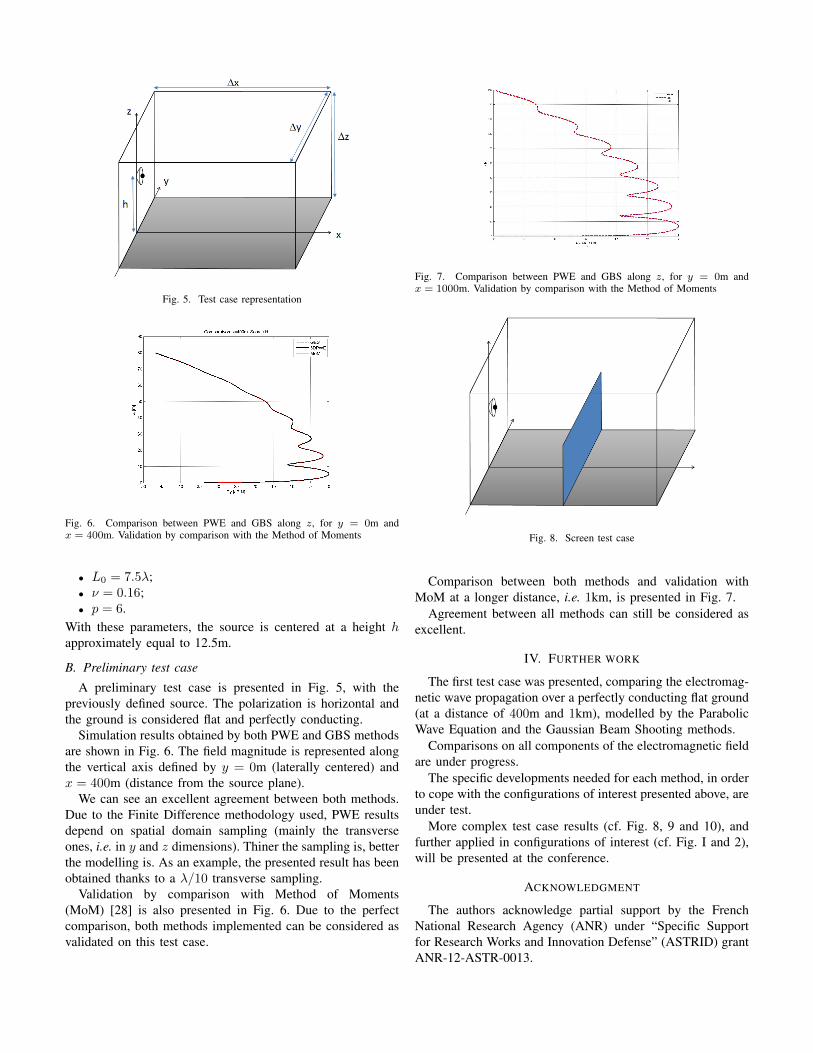
Fig. 5. Test case representation
Fig. 6. Comparison between PWE and GBS along z, for y = 0m andx = 400m. Validation by comparison with the Method of Moments
• L0 = 7.5λ;• ν = 0.16;• p = 6.
With these parameters, the source is centered at a height happroximately equal to 12.5m.
B. Preliminary test case
A preliminary test case is presented in Fig. 5, with thepreviously defined source. The polarization is horizontal andthe ground is considered flat and perfectly conducting.
Simulation results obtained by both PWE and GBS methodsare shown in Fig. 6. The field magnitude is represented alongthe vertical axis defined by y = 0m (laterally centered) andx = 400m (distance from the source plane).
We can see an excellent agreement between both methods.Due to the Finite Difference methodology used, PWE resultsdepend on spatial domain sampling (mainly the transverseones, i.e. in y and z dimensions). Thiner the sampling is, betterthe modelling is. As an example, the presented result has beenobtained thanks to a λ/10 transverse sampling.
Validation by comparison with Method of Moments(MoM) [28] is also presented in Fig. 6. Due to the perfectcomparison, both methods implemented can be considered asvalidated on this test case.
Fig. 7. Comparison between PWE and GBS along z, for y = 0m andx = 1000m. Validation by comparison with the Method of Moments
Fig. 8. Screen test case
Comparison between both methods and validation withMoM at a longer distance, i.e. 1km, is presented in Fig. 7.
Agreement between all methods can still be considered asexcellent.
IV. FURTHER WORK
The first test case was presented, comparing the electromag-netic wave propagation over a perfectly conducting flat ground(at a distance of 400m and 1km), modelled by the ParabolicWave Equation and the Gaussian Beam Shooting methods.
Comparisons on all components of the electromagnetic fieldare under progress.
The specific developments needed for each method, in orderto cope with the configurations of interest presented above, areunder test.
More complex test case results (cf. Fig. 8, 9 and 10), andfurther applied in configurations of interest (cf. Fig. I and 2),will be presented at the conference.
ACKNOWLEDGMENT
The authors acknowledge partial support by the FrenchNational Research Agency (ANR) under “Specific Supportfor Research Works and Innovation Defense” (ASTRID) grantANR-12-ASTR-0013.
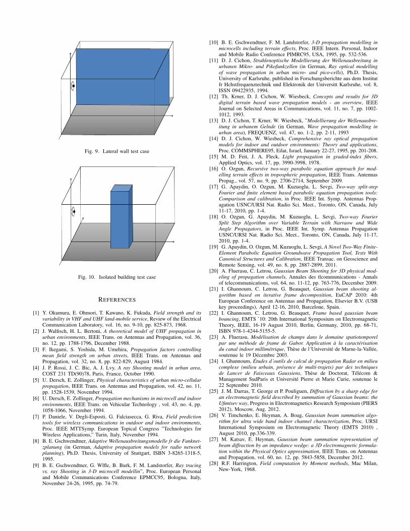
Fig. 9. Lateral wall test case
Fig. 10. Isolated building test case
REFERENCES
[1] Y. Okumura, E. Ohmori, T. Kawano, K. Fukuda, Field strength and itsvariability in VHF and UHF land-mobile service, Review of the ElectricalCommunication Laboratory, vol. 16, no. 9-10, pp. 825-873, 1968.
[2] J. Walfisch, H. L. Bertoni, A theoretical model of UHF propagation inurban environments, IEEE Trans. on Antennas and Propagation, vol. 36,no. 12, pp. 1788-1796, December 1988.
[3] F. Ikegami, S. Yoshida, M. Umehira, Propagation factors controllingmean field strength on urban streets, IEEE Trans. on Antennas andPropagation, vol. 32, no. 8, pp. 822-829, August 1984.
[4] J. P. Rossi, J. C. Bic, A. J. Lvy, A ray Shooting model in urban area,COST 231 TD(90)78, Paris, France, October 1990.
[5] U. Dersch, E. Zollinger, Physical characteristics of urban micro-cellularpropagation, IEEE Trans. on Antennas and Propagation, vol. 42, no. 11,pp. 1528-1539, November 1994.
[6] U. Dersch, E. Zollinger, Propagation mechanisms in microcell and indoorenvironments, IEEE Trans. on Vehicular Technology , vol. 43, no. 4, pp.1058-1066, November 1994.
[7] P. Daniele, V. Degli-Esposti, G. Falciasecca, G. Riva, Field predictiontools for wireless communications in outdoor and indoor environments,Proc. IEEE MTTSymp. European Topical Congress ”Technologies forWireless Applications,” Turin, Italy, November 1994.
[8] B. E. Gschwendtner, Adaptive Wellenausbreitungsmodelle fr die Funknet-zplanung (in German, Adaptive propagation models for radio networkplanning), Ph.D. Thesis, University of Stuttgart, ISBN 3-8265-1318-5,1995.
[9] B. E. Gschwendtner, G. Wlfle, B. Burk, F. M. Landstorfer, Ray tracingvs. ray Shooting in 3-D microcell modellin”, Proc. European Personaland Mobile Communications Conference EPMCC95, Bologna, Italy,November 24-26, 1995, pp. 74-79.
[10] B. E. Gschwendtner, F. M. Landstorfer, 3-D propagation modelling inmicrocells including terrain effects, Proc. IEEE Intern. Personal, Indoorand Mobile Radio Conference PIMRC95, USA, 1995, pp. 532-536.
[11] D. J. Cichon, Strahlenoptische Modellierung der Wellenausbreitung inurbanen Mikro- und Pikofunkzellen (in German, Ray optical modellingof wave propagation in urban micro- and pico-cells), Ph.D. Thesis,University of Karlsruhe, published in Forschungsberichte aus dem Institutfr Hchstfrequenztechnik und Elektronik der Universitt Karlsruhe, vol. 8,ISSN 09422935, 1994.
[12] Th. Krner, D. J. Cichon, W. Wiesbeck, Concepts and results for 3Ddigital terrain based wave propagation models - an overview, IEEEJournal on Selected Areas in Communications, vol. 11, no. 7, pp. 1002-1012, 1993.
[13] D. J. Cichon, T. Krner, W. Wiesbeck, ”Modellierung der Wellenausbre-itung in urbanem Gelnde (in German, Wave propagation modelling inurban area), FREQUENZ, vol. 47, no. 1-2, pp. 2-11, 1993
[14] D. J. Cichon, W. Wiesbeck, Comprehensive ray optical propagationmodels for indoor and outdoor environments: Theory and applications,Proc. COMMSPHERE95, Eilat, Israel, January 22-27, 1995, pp. 201-208.
[15] M. D. Feit, J. A. Fleck, Light propagation in graded-index fibers,Applied Optics, vol. 17, pp. 3990-3998, 1978.
[16] O. Ozgun, Recursive two-way parabolic equation approach for mod-elling terrain effects in tropospheric propagation, IEEE Trans. AntennasPropag., vol. 57, no. 9, pp. 2706-2714, September 2009.
[17] G. Apaydin, O. Ozgun, M. Kuzuoglu, L. Sevgi, Two-way split-stepFourier and finite element based parabolic equation propagation tools:Comparison and calibration, in Proc. IEEE Int. Symp. Antennas Prop-agation USNC/URSI Nat. Radio Sci. Meet., Toronto, ON, Canada, July11-17, 2010, pp. 1-4.
[18] O. Ozgun, G. Apaydin, M. Kuzuoglu, L. Sevgi, Two-way FourierSplit Step Algorithm over Variable Terrain with Narraow and WideAngle Propagators, in Proc. IEEE Int. Symp. Antennas PropagationUSNC/URSI Nat. Radio Sci. Meet., Toronto, ON, Canada, July 11-17,2010, pp. 1-4.
[19] G. Apaydin, O. Ozgun, M. Kuzuoglu, L. Sevgi, A Novel Two-Way Finite-Element Parabolic Equation Groundwave Propagation Tool, Tests WithCanonical Structures and Calibration, IEEE Transac. on Geoscience andRemote Sensing, vol. 49, no. 8, pp. 2887-2899, 2011.
[20] A. Fluerasu, C. Letrou, Gaussian Beam Shooting for 3D physical mod-eling of propagation channels, Annales des tlcommunications - Annalsof telecommunications, vol. 64, no. 11-12, pp. 763-776, December 2009.
[21] I. Ghannoum, C. Letrou, G. Beauquet, Gaussian beam shooting al-gorithm based on iterative frame decomposition, EuCAP 2010: 4thEuropean Conference on Antennas and Propagation, Elsevier B.V. (USBkey proceedings), April 12-16, 2010, Barcelone, Spain.
[22] I. Ghannoum, C. Letrou, G. Beauquet, Frame based gaussian beambouncing, EMTS ’10: 20th International Symposium on ElectromagneticTheory, IEEE, 16-19 August 2010, Berlin, Germany, 2010, pp. 68-71,ISBN 978-1-4244-5155-5.
[23] A. Fluerasu, Modelisation de champs dans le domaine spatiotemporelpar une methode de frame de Gabor. Application a la caracterisationdu canal indoor millimetrique, These de l´Universite de Marne-la-Vallee,soutenue le 19 Decembre 2003.
[24] I. Ghannoum, Etudes d´outils de calcul de propagation Radar en milieucomplexe (milieu urbain, presence de multi-trajets) par des techniquesde Lancer de Faisceaux Gaussiens, These de Doctorat, Telecom &Management SudParis et Universite Pierre et Marie Curie, soutenue le22 Septembre 2010.
[25] J. M. Darras, T. George et P. Pouliguen, Diffraction by a sharp edge foran electromagnetic field described by summation of Gaussian beams: theUfimtsev way, Progress in Electromagnetics Research Symposium (PIERS2012), Moscow, Aug. 2012.
[26] V. Timchenko, E. Heyman, A. Boag, Gaussian beam summation algo-rithm for ultra wide band indoor channel characterization, Proc. URSIInternational Symposium on Electromagnetic Theory (EMTS 2010) ,August 2010, pp.336-339.
[27] M. Katsav, E. Heyman, Gaussian beam summation representation ofbeam diffraction by an impedance wedge: a 3D electromagnetic formula-tion within the Physical Optics approximation, IEEE Trans. on Antennasand Propagation, vol. 60, no. 12, pp. 5843-5858, December 2012.
[28] R.F. Harrington, Field computation by Moment methods, Mac Milan,New-York, 1968.
Related Documents


![FeiPu arXiv:2008.08267v3 [math.PR] 1 Nov 2020 · arXiv:2008.08267v3 [math.PR] 1 Nov 2020 Gaussian fluctuation for spatial average of parabolic Anderson model with Neumann/Dirichlet/periodic](https://static.cupdf.com/doc/110x72/60c96c3295781761cd34edc8/feipu-arxiv200808267v3-mathpr-1-nov-2020-arxiv200808267v3-mathpr-1-nov.jpg)


