VISIT ANALOG.COM Vol 53 No 4, December 2019 StudentZone— ADALM2000: Zener Diode Regulator Doug Mercer , Consulting Fellow and Antoniu Miclaus, System Applications Engineer Objectives A voltage regulator is a circuit used to maintain a constant output voltage at a load independent of changes in the load current. For example, the load could be a microcontroller-based system that requires a constant supply voltage even as its demand for current varies with system activity. The Zener diode regulator in Figure 1 offers a very simplified way to maintain the load voltage, V L , at the same value as the reverse breakdown voltage of the Zener diode, provided that the load resistance, R L , remains higher than some lower limit. The voltage source, V IN , and resistor, R S , model the Thévenin resis- tance of a possible circuit that has converted a high voltage such as the 120 V ac mains power to an unregulated and unfiltered lower dc voltage source. Materials X ADALM2000 active learning module X Solderless breadboard X One 1 kΩ resistor (R S ) X One 5 kΩ variable resistor, potentiometer (R L ) X One Zener diode (1N4735 or similar) Directions Build the circuit shown in Figure 1 on your solderless breadboard using the 1N4735 6.2 V Zener diode. Use AWG1 (5 V constant) and the –5 V Vn user supply to establish the dc supply V IN . Use various fixed and variable resistors for R L . RL Rs D1 1N4735 1+ 1– 2– 2+ W1 Vn Figure 1. Zener diode regulator. Vn 1– 1 kΩ RL 1N4735 W1 2+ 2– 1+ Figure 2. Zener diode regulator breadboard circuit.

Welcome message from author
This document is posted to help you gain knowledge. Please leave a comment to let me know what you think about it! Share it to your friends and learn new things together.
Transcript
VISIT ANALOG.COM
Vol 53 No 4, December 2019
StudentZone— ADALM2000: Zener Diode RegulatorDoug Mercer , Consulting Fellow and Antoniu Miclaus , System Applications Engineer
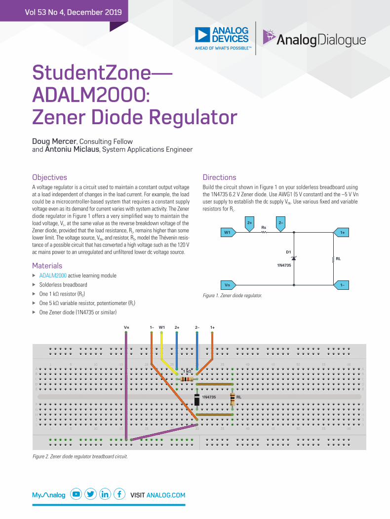
ObjectivesA voltage regulator is a circuit used to maintain a constant output voltage at a load independent of changes in the load current. For example, the load could be a microcontroller-based system that requires a constant supply voltage even as its demand for current varies with system activity. The Zener diode regulator in Figure 1 offers a very simplified way to maintain the load voltage, VL, at the same value as the reverse breakdown voltage of the Zener diode, provided that the load resistance, RL, remains higher than some lower limit. The voltage source, VIN, and resistor, RS, model the Thévenin resis-tance of a possible circuit that has converted a high voltage such as the 120 V ac mains power to an unregulated and unfiltered lower dc voltage source.
Materials X ADALM2000 active learning module X Solderless breadboard X One 1 kΩ resistor (RS) X One 5 kΩ variable resistor, potentiometer (RL) X One Zener diode (1N4735 or similar)
DirectionsBuild the circuit shown in Figure 1 on your solderless breadboard using the 1N4735 6.2 V Zener diode. Use AWG1 (5 V constant) and the –5 V Vn user supply to establish the dc supply VIN. Use various fixed and variable resistors for RL.
RL
Rs
D1
1N4735
1+
1–
2–2+
W1
Vn
Figure 1. Zener diode regulator.
Vn 1–
1 kΩ
RL1N4735
W1 2+ 2– 1+
Figure 2. Zener diode regulator breadboard circuit.

2 StudentZone—ADALM2000: Zener Diode Regulator
ProcedureStep 1Monitor and report the load voltage VL by using the Scopy Voltmeter instrument to measure VL for RL equal to:
X Open circuit (see Figure 3) X 10 kΩ (see Figure 4) X 1 kΩ (see Figure 5) X 100 Ω (see Figure 6)
Figure 3. RL = open circuit Zener diode regulator waveform.
Figure 4. RL = 10 kΩ Zener diode regulator waveform.
Figure 5. RL = 1 kΩ Zener diode regulator waveform.
Figure 6. RL = 100 Ω Zener diode regulator waveform.
Step 2Replace the load RL with a 5 kΩ potentiometer and adjust the potentiometer to determine the minimum value of RL for which VL remains within 10% of the Zener voltage, VZ. Measure and report the resistance to which you set the potentiometer. How does this resistance relate to the value of RS?
Further ExplorationInvestigate the current/voltage characteristic curve for the Zener diode using the same technique described in Step 2 by measuring the current in RS with Scope Channel 2 and plotting the voltage across the Zener vs. the current in the Oscilloscope XY mode. Be sure to adjust the horizontal volt-age range and offset to include the 6.2 V breakdown voltage. Discuss your results, in particular the ways in which the Zener diode is similar to, and different from, a conventional diode.
Driving Larger Load CurrentsAs we saw in the simple Zener diode regulator in Figure 1, the maximum load current is determined by resistor RS. Also, the circuit is very inefficient for smaller load currents with respect to the maximum in that the excess current flows in the Zener when not flowing in the load. The inclusion of an emitter follower or Darlington emitter follower current amplifier can greatly improve the efficiency of this regulator circuit as shown in Figure 2.
Additional Materials X Two NPN transistors (2N3904 and TIP31) X Two small signal diodes (1N914 or similar)
Q2
Q1
RS
D3
D2
D1
Q1
RL
RS
D2
D1
VL
Figure 7. Adding a current amplifier stage.

VISIT ANALOG.COM
For regional headquarters, sales, and distributors or to contact customer service and technical support, visit analog.com/contact.
Ask our ADI technology experts tough questions, browse FAQs, or join a conversation at the EngineerZone Online Support Community. Visit ez.analog.com.
©2019 Analog Devices, Inc. All rights reserved. Trademarks and registered trademarks are the property of their respective owners.
DirectionsBuild either of the circuits shown in Figure 2 on your solderless breadboard using the 1N4735 6.2 V Zener diode as D1 and a 2N3904 or TIP31 power transistor for Q1. Q2 can be a 2N3904 and D2, D3 can be a 1N914.
The extra diode D2 is added in series with the Zener to partially cancel the additional VBE drop due to the emitter follower Q1. Likewise, in the Darlington configuration, two diodes (D2, D3) are added to again partially cancel the two VBE drop of the Darlington follower.
QuestionUsing the circuit in Figure 1, compute the resistance, RL, for which the VL
value is at 20% of the Zener voltage VZ.
You can find the answers at the StudentZone blog.
About the AuthorDoug Mercer received his B.S.E.E. degree from Rensselaer Polytechnic Institute (RPI) in 1977. Since joining Analog Devices in 1977, he has contributed directly or indirectly to more than 30 data converter products and he holds 13 patents. He was appointed to the position of ADI Fellow in 1995. In 2009, he transitioned from full-time work and has continued consulting at ADI as a Fellow Emeritus contributing to the Active Learning Program. In 2016 he was named Engineer in Residence within the ECSE department at RPI.He can be reached at [email protected].
About the AuthorAntoniu Miclaus is a system applications engineer at Analog Devices, where he works on ADI academic programs, as well as embedded software for Circuits from the Lab®, QA automation, and process management. He started working at Analog Devices in February 2017 in Cluj-Napoca, Romania. He is currently an M.Sc. student in the software engineering master’s program at Babes-Bolyai University and he has a B.Eng. in electronics and telecommunications from Technical University of Cluj-Napoca. He can be reached at [email protected].
Related Documents