Purchasing Section P: 515-239-1310 F: 515-239-1538 800 Lincoln Way, Ames, Iowa 50010 [email protected] November 21, 2018 ADDENDUM NO.2 to the Iowa Department of Transportation Proposal No. 21706 Adair Facility Upgrade Date: November 28, 2018 Notice To Bidders: This Addendum is issued to incorporate the following additions, deletions, corrections, and/or clarifications to the terms or specifications and shall hereby be considered a part of the final contract documents. This Addendum shall supersede, modify and/or change all statements to the contrary in the bid proposal and shall take precedence over previous terms or specifications. Corrections: To Specification Section(s) Section 01 9113 General Commissioning Requirements a. DELETE paragraph 1.02B Building Envelope in its entirety. b. DELETE paragraph 1.02E Electrical Systems in its entirety. c. DELETE paragraph 1.02F Electronic Safety and Security in its entirety. SECTION 22 0800 Commissioning of Plumbing a. ADD Section 22 0800 Commissioning of Plumbing as attached to this addendum. SECTION 23 0800 Commissioning of HVAC b. ADD Section 23 0800 Commissioning of HVAC as attached to this addendum. SECTION 23 5523 Gas Fired Radiant Heaters c. REVISE Part 2.1.D.3 to read as follows: “The scroll of the pump shall be cast iron with a minimum metal thickness of approximately 3/16 inch. The impeller wheel shall be pressure cast 319-alloy aluminum with a minimum metal thickness of approximately 3/32 inch.” d. ADD Part 2.1.E.1.d as follows: “Reflectors shall be manufacture’s standard 14-1/2” wide reflectors” e. ADD Part 2.1.G.1.a as follows: “Thermostats located in wash bay areas shall have splash guard covers.”

Welcome message from author
This document is posted to help you gain knowledge. Please leave a comment to let me know what you think about it! Share it to your friends and learn new things together.
Transcript

Purchasing Section P: 515-239-1310 F: 515-239-1538 800 Lincoln Way, Ames, Iowa 50010 [email protected]
November 21, 2018
ADDENDUM NO.2 to the
Iowa Department of Transportation Proposal No. 21706
Adair Facility Upgrade
Date: November 28, 2018 Notice To Bidders: This Addendum is issued to incorporate the following additions, deletions, corrections, and/or clarifications to the terms or specifications and shall hereby be considered a part of the final contract documents. This Addendum shall supersede, modify and/or change all statements to the contrary in the bid proposal and shall take precedence over previous terms or specifications.
Corrections:
To Specification Section(s)
Section 01 9113 General Commissioning Requirements
a. DELETE paragraph 1.02B Building Envelope in its entirety.
b. DELETE paragraph 1.02E Electrical Systems in its entirety.
c. DELETE paragraph 1.02F Electronic Safety and Security in its entirety.
SECTION 22 0800 Commissioning of Plumbing
a. ADD Section 22 0800 Commissioning of Plumbing as attached to this addendum.
SECTION 23 0800 Commissioning of HVAC
b. ADD Section 23 0800 Commissioning of HVAC as attached to this addendum.
SECTION 23 5523 Gas Fired Radiant Heaters
c. REVISE Part 2.1.D.3 to read as follows: “The scroll of the pump shall be cast iron with a minimum metal thickness of approximately 3/16 inch. The impeller wheel shall be pressure cast 319-alloy aluminum with a minimum metal thickness of approximately 3/32 inch.”
d. ADD Part 2.1.E.1.d as follows: “Reflectors shall be manufacture’s standard 14-1/2” wide reflectors”
e. ADD Part 2.1.G.1.a as follows: “Thermostats located in wash bay areas shall have splash guard covers.”

Purchasing Section P: 515-239-1310 F: 515-239-1538 800 Lincoln Way, Ames, Iowa 50010 [email protected]
f. REVISE Part 2.1.H.4 to read as follows: “All heat exchanger (tubing) connections shall be made with stainless steel couplings assemblies. All couplings shall be in all piping locations. Unlined couplings are not acceptable.”
g. DELETE Part 2.1.I Condensate Piping in its entirety.
Additions: Specification Section 22 0800 and Specification Section 23 0800
To Drawing(s)
SHEET M101
a. REPLACE sheet as per attached to this addendum.
SHEET M101A
b. REPLACE sheet as per attached to this addendum.
SHEET M201
c. REPLACE sheet as per attached to this addendum.
SHEET M201A
d. REPLACE sheet as per attached to this addendum.
SHEET M600
e. REPLACE sheet as per attached to this addendum.
SHEET E201
f. REPLACE sheet as per attached to this addendum.
SHEET E201A
g. REPLACE sheet as per attached to this addendum.
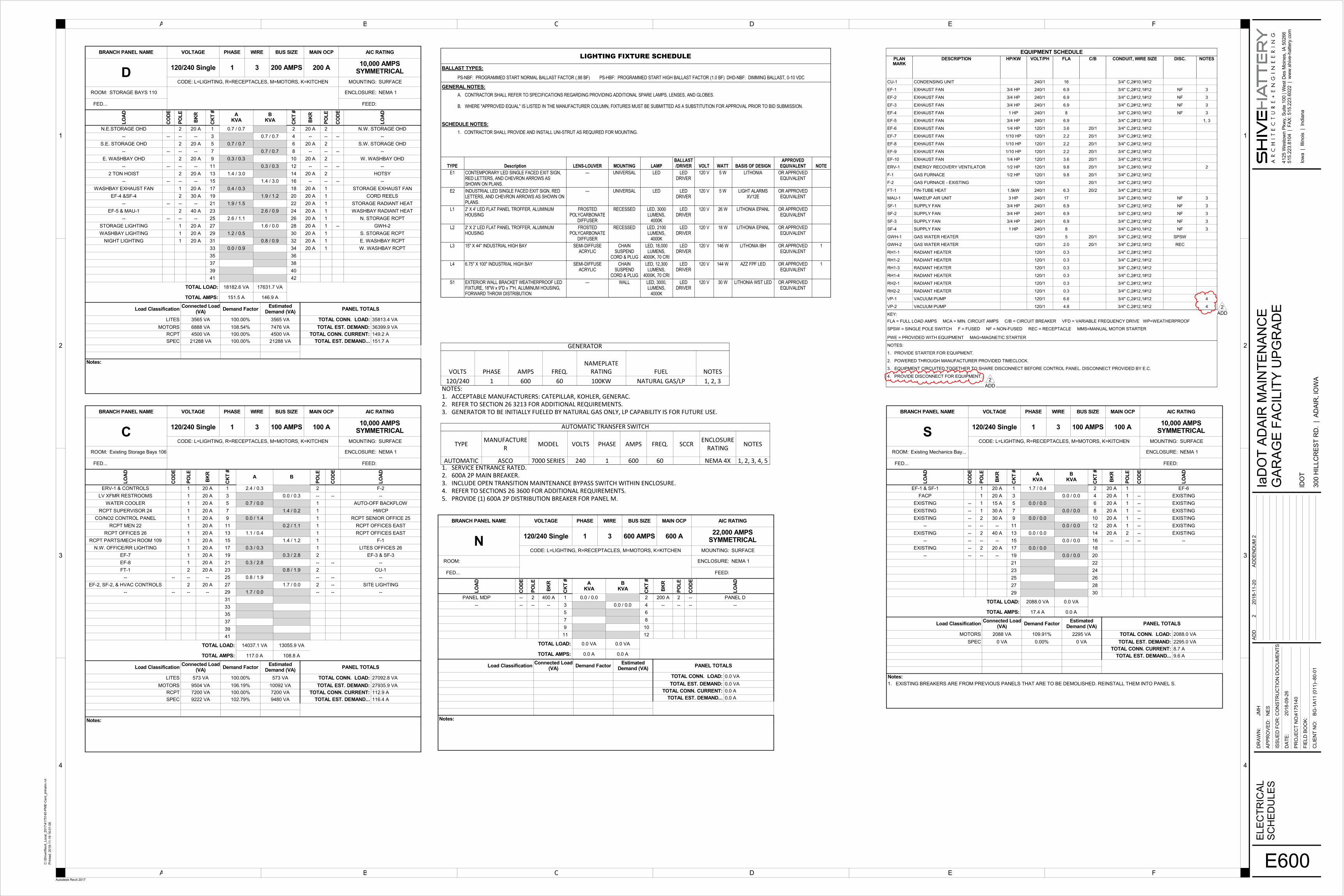
SHEET E600
h. REPLACE sheet as per attached to this addendum.
All Bidders must sign and return this Addendum for the bid opportunity referenced above. Failure to do so may subject the Bidder to disqualification. If a bid response has already been submitted, this Addendum shall be signed and emailed or faxed to the Purchasing Section prior to the scheduled solicitation response date. _________________________________ _________________________________ Company Name (please print) Date
_________________________________ Signature Sincerely, Jody McNaughton, Purchasing Agent Phone No. 515-239-1298 Fax No. 515-239-1538 [email protected]

IaDOT Adair Maintenance Facility Upgrade
COMMISSIONING OF
PLUMBING IaDOT# BG-1A11(011)--80-01 SH Project # 4175140_WO33
Issued for Addendum No. 2 11-20-2018
22 0800-1
SECTION 22 0800
COMMISSIONING OF PLUMBING
PART 1 – GENERAL
1.1 SUMMARY
A. The Owner will contract separately with a 3rd party to act as Commissioning Authority.
B. The Contractor and all Subcontractors shall coordinate their activities with those of the System Commissioning Authority (CxA) as outlined in this section.
C. This section includes commissioning and testing procedures of the following building components and/or system:
1. Domestic Water Systems
a. Water Heaters
b. Hot Water Circulating Pumps
D. The System Commissioning Authority’s Scope of Work shall include the following tasks as specified below. No work outlined in this specification shall diminish any contractual responsibility of the contractor, subcontractors or vendors outlined in the contract documents. The CxA’s work tasks shall include, but not necessarily be limited to:
1. Commissioning Plan Preparation
2. Submittal Review
3. Field Installation Verification
4. Start-Up Verification Checklists (SVC)
5. Functional Performance Testing (FPT)
6. Record Drawing/Specification Coordination
7. Coordination of Owner Training
8. System Commissioning Final Report
E. The Contractor and subcontractors shall be responsible for providing equipment, personnel and material to execute the commissioning procedures as outlined in the commissioning plan for the project and in accordance with the commissioning schedule.
PART 2 – PRODUCTS - NOT USED
PART 3 – EXECUTION
3.1 PREPARATION AND RESPONSIBILITIES
A. The contractor, each subcontractor and vendor responsible for any system, equipment or component device shall be responsible for preparation of those systems, equipment and component devices for Field Installation Verification, Start-Up Verification Testing and Functional Performance Testing.

IaDOT Adair Maintenance Facility Upgrade IaDOT# BG-1A11(011)--80-01
SH Project # 4175140_WO33
COMMISSIONING OF PLUMBING 22 0800-2 Issued for Addendum No. 2
11-20-2018
B. The contractor or the responsible subcontractor shall certify to the Commissioning Authority that a system to be commissioned is ready for each commissioning phase prior to initiation of commissioning procedure execution.
C. The responsible contractor or subcontractor shall provide the services of qualified technicians to operate the commissioned systems during the execution of either Start-Up Verification Testing or Functional Performance Testing procedures. Operation of these systems during the execution of Functional Performance Testing procedures shall be under the supervision of and at the direction of the Commissioning Authority.
D. The Commissioning Authority shall coordinate, witness, and supervise the building and/or system commissioning and testing procedures.
E. Contractor shall provide ladders and scaffolding as required to permit the Commissioning Authority to directly observe the installation and performance of the equipment being tested.
3.2 COMMISSIONING PLAN
A. The Commissioning Authority will prepare a Commissioning Plan that outlines all work involved in commissioning the project systems listed above.
B. The system commissioning plan shall include:
1. A summary of each system to be commissioned, each commissioning procedure to be executed, all documentation required for the final commissioning report and responsibilities for delivering each executing and documenting each element of the commissioning plan.
2. Commissioning schedules and priorities.
3. Documentation requirements and format (checklists for recording inspections, start up, functional performance test, unit capacities, installation and operations instructions, etc.)
C. The Commissioning Authority shall review project commissioning plan with the Owner, the Contractor and/or his appointed representatives, contractors, vendors, and all other affected parties. Items reviewed shall include participant responsibilities, sequence of events, functional performance tests, documentation requirements, verification procedures, operator training and all other items deemed necessary by the Owner.
3.3 SUBMITTAL REVIEW
A. The Commissioning Authority shall review all shop drawings pertinent to the systems and equipment to be commissioned. The Commissioning Authority shall report any discrepancies between the construction documents and the submittals that would affect the commissioning process. The Commissioning Authority shall document the resolution of discrepancies.
B. The Commissioning Authority’s shop drawing review will be for the purpose of commissioning only. The CxA will have no approval authority and will act or as an advisor to the Owner's Representative.
C. The Commissioning Authority shall consult with the Owner's Representative regarding any changes, corrections, deletions that may be necessary.
3.4 FIELD INSTALLATION VERIFICATION
A. Prior to performance of the start up verification, all Field Installation Verification (FIV) procedures shall be complete. No performance testing shall be performed until work included in this section is completed.

IaDOT Adair Maintenance Facility Upgrade IaDOT# BG-1A11(011)--80-01
SH Project # 4175140_WO33
COMMISSIONING OF PLUMBING
Issued for Addendum No. 2 11-20-2018
22 0800-3
B. Contractor shall inspect all equipment, ensure systems have been put properly and completely installed. Contractor shall ensure all construction debris and dirt have been removed and that all systems, where applicable, have been cleaned. All equipment shall have been inspected and certified ready for startup. Contractor to pre-check all Start-Up Verification Checklists (SVC) and Functional Performance Tests (FPT) prior to Commissioning Authority (CxA) arriving on site.
1. Contractor shall submit an initialed SVC and FPT for each piece of equipment and system to the Commissioning Authority prior to on site verification by the CxA.
C. The Commissioning Authority shall inspect each system, component or device included in a given system. All applicable FIV procedures shall be executed and accepted as complete and acceptable prior to initiation of Start up activities.
3.5 START-UP VERIFICATION CHECKLISTS (SVC)
A. Commissioning Authority shall establish with the Contractor, Subcontractors and vendors a schedule for each system and major piece of equipment to be started and tested.
B. Commissioning Authority shall be responsible for completion of the Start-Up Verifivcation Checklists.
C. Tests shall be performed on each system and piece of equipment scheduled in the Commissioning Plan. All tests shall be fully documented and all deviations from acceptance criteria recorded. The Commissioning Authority shall recommend acceptance or rejection of each Start-Up Verification Test based on test results.
D. For any system, sub-system, component or device that fails a Start-Up Verification Test, the responsible Contractor or Subcontractor shall make all necessary adjustments, repairs or revision to that system, sub-system or component to correct any deficiencies.
E. Upon correction of deficiencies, the responsible Contractor or Subcontractor shall provide appropriate qualified personnel to operate the system for any additional testing that may be required to achieve an acceptable result.
F. The Commissioning Authority shall coordinate re-test of all rejected systems/equipment after corrective measures have been performed.
G. The Commissioning Authority shall prepare a list of off-season systems that must be tested after the normal Commissioning Period to properly establish system performance.
3.6 FUNCTIONAL PERFORMANCE TESTING (FPT)
A. The Commissioning Authority shall conduct all Functional Performance Testing. The Contractor or Subcontractor responsible for the commissioned system shall provide appropriate qualified personnel to operate the system being tested under the supervision of the Commissioning Authority.
B. Equipment, systems, sub-systems, and components shall be tested and evaluated for conformance with the performance requirements outlined in the Basis of Design Document, the Functional Performance Test (FPT) protocols, and the Contract Documents. All testing and balancing and Start-Up Verification Tests must be complete for all systems before the FPT can begin unless directed otherwise by the CxA.

IaDOT Adair Maintenance Facility Upgrade IaDOT# BG-1A11(011)--80-01
SH Project # 4175140_WO33
COMMISSIONING OF PLUMBING 22 0800-4 Issued for Addendum No. 2
11-20-2018
C. Tests shall be performed on each system scheduled in the Commissioning Plan. All tests shall be fully documented and all deviations from acceptance criteria recorded. The Commissioning Authority shall recommend acceptance or rejection of each Functional Performance Test based on test results.
1. Multiple identical pieces of non-critical equipment may be functionally tested using a sampling strategy.
a. A minor size or capacity difference does not constitute a difference. Major application differences or sequence of operation differences in similar equipment voids their commonality.
2. No sampling is allowed by the Contractor or Subcontractor in System Verification Checklists.
3. The sampling strategy to be followed for this project is a 20% Sampling/10% Failure Method.
a. Commissioning Authority shall randomly test 20% of each group of similar equipment. If there are less than three (3) units in a group, all units of that group shall be tested. This represents the first sample 20%.
b. If 10% of the units of the first sample fail their respective Functional Performance Test (FPT), the CxA shall test a second random 20% sample.
c. If 10% of the second sample fails the FPT’s, Commissioning Authority shall test all remaining units in the group.
d. If at any point during testing there are frequent failures occurring, and the testing is moving towards more troubleshooting than verification, the Commissioning Authority shall stop the testing and ask the responsible Contractor or Subcontractor to perform and document a checkout of the units remaining for functionality prior to continuation of the Functional Performance Testing.
D. For any system, sub-system or component deemed unacceptable as a result of the appropriate Functional Performance Test, the responsible Contractor or Subcontractor shall make all necessary adjustments, repairs or revision to that system, sub-system or component to correct any deficiencies.
E. Corrections made during functional performance testing are generally prohibited to avoid consuming the time of personnel waiting for the test but not involved in the correction. Exceptions will be allowed at the discretion of the Commissioning Authority if the cause of the failure is obvious and the corrective action can be made in less than ten minutes. If corrections are made under this exception the failure and correction will be noted on the functional performance test forms.
F. Upon correction of deficiencies, the responsible Contractor or Subcontractor shall provide appropriate qualified personnel to operate the system for any additional testing that may be required to achieve an acceptable result.
3.7 RECORD DRAWING VERIFICATION
A. The Commissioning Authority shall review all Record Drawings for general conformance with the constructed condition.
B. Review all documentation of systems and components and compare to actual on-site operation and hardware.

IaDOT Adair Maintenance Facility Upgrade IaDOT# BG-1A11(011)--80-01
SH Project # 4175140_WO33
COMMISSIONING OF PLUMBING
Issued for Addendum No. 2 11-20-2018
22 0800-5
C. Review all Operation and Maintenance manual data submitted for completeness and accuracy.
D. Verify to the Contractor and the Owner's Representative that all system documentation is current.
3.8 OWNER TRAINING
A. Upon completion of training, the Commissioning Authority shall include verification of training in the Final Commissioning Report.
3.9 SYSTEM COMMISSIONING FINAL REPORT
A. The Commissioning Report shall include as a minimum the following data:
1. Documentation of all checklists completed in the installation verification.
2. Documentation of all tests performed, initial rejected tests and final acceptance tests, of all work performed during the start-up function.
3. All uncorrectable deviations from established performance criteria.
3.10 OPERATIONS AND MAINTENANCE MANUALS
A. The Commissioning Authority shall review the Operations and Maintenance Manuals and support documentation as part of this project. The documentation should include:
1. System Descriptions, Operating Conditions and Setpoint Parameters for each commissioned system.
2. Equipment and Systems installation, Operation and Maintenance Data Sheets.
3. Standard Operating Procedure for all commissioned systems and components including start up. Normal operation, shut down and emergency procedures.
4. Preventative Maintenance Procedure for all critical systems and components.
B. The Contractor shall coordinate assembly of all appropriate equipment and system data sheets by installing contractors, subcontractors and suppliers.
C. The Commissioning Authority shall be responsible for final review of O&M Manuals, operating procedures and preventative maintenance procedures so that this data can be used effectively by the operations and maintenance personnel.
END OF SECTION

IaDOT Adair Maintenance Facility Upgrade IaDOT# BG-1A11(011)--80-01
SH Project # 4175140_WO33
COMMISSIONING OF PLUMBING 22 0800-6 Issued for Addendum No. 2
11-20-2018

IaDOT Adair Maintenance Facility Upgrade
COMMISSIONING OF HVAC
IaDOT# BG-1A11(011)--80-01 SH Project # 4175140_WO33
Issued for Addendum No. 2 11-20-2018
23 0800-1
SECTION 23 0800
COMMISSIONING OF HVAC
PART 1 – GENERAL
1.1 SUMMARY
A. The Owner will contract separately with a 3rd party to act as Commissionig Authority.
B. The Contractor and all Subcontractors shall coordinate their activities with those of the Commissioning Authority (CxA) as outlined in this section.
C. This section includes commissioning and testing procedures of the following building components and/or system:
1. HVAC & Exhaust Systems, including, but not limited to:
a. Make-Up Air Handling Units
b. Gas Fired Radiant Heaters
c. Energy Recovery Ventilators
d. Furnace
e. Air Cooled Condensing Unit
f. Exhaust and Supply Fans
g. Fin Tube Radiation Heaters
h. CO and NO2 Monitoring Equipment
2. HVAC Environmental Control Systems (Temperature and Pressure Controls)
D. The System Commissioning Authority's Scope of Work shall include the following tasks as specified below. No work outlined in this specification shall diminish any contractual responsibility of the contractor, subcontractors or vendors outlined in the contract documents . The CxA’s work tasks shall include, but not necessarily be limited to:
1. Commissioning Plan Preparation
2. Submittal Review
3. Field Installation Verification
4. Start-Up Verification Checklists (SVC)
5. Functional Performance Testing (FPT)
6. Coordination of Owner Training
7. System Commissioning Final Report
E. The Contractor and subcontractors shall be responsible for providing equipment, personnel and material to execute the commissioning procedures as outlined in the commissioning plan for the project and in accordance with the commissioning schedule.
IaDOT Adair Maintenance Facility Upgrade IaDOT# BG-1A11(011)--80-01
SH Project # 4175140_WO33
COMMISSIONING OF HVAC 23 0800-2 Issued for Addendum No. 2
11-20-2018
PART 2 – PRODUCTS - Not Used
PART 3 – EXECUTION
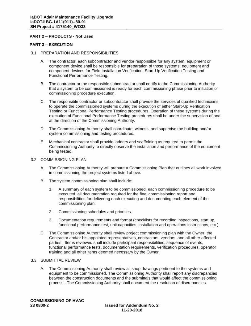
3.1 PREPARATION AND RESPONSIBILITIES
A. The contractor, each subcontractor and vendor responsible for any system, equipment or component device shall be responsible for preparation of those systems, equipment and component devices for Field Installation Verification, Start-Up Verification Testing and Functional Performance Testing.
B. The contractor or the responsible subcontractor shall certify to the Commissioning Authority that a system to be commissioned is ready for each commissioning phase prior to initiation of commissioning procedure execution.
C. The responsible contractor or subcontractor shall provide the services of qualified technicians to operate the commissioned systems during the execution of either Start-Up Verification Testing or Functional Performance Testing procedures. Operation of these systems during the execution of Functional Performance Testing procedures shall be under the supervision of and at the direction of the Commissioning Authority.
D. The Commissioning Authority shall coordinate, witness, and supervise the building and/or system commissioning and testing procedures.
E. Mechanical contractor shall provide ladders and scaffolding as required to permit the Commissioning Authority to directly observe the installation and performance of the equipment being tested.
3.2 COMMISSIONING PLAN
A. The Commissioning Authority will prepare a Commissioning Plan that outlines all work involved in commissioning the project systems listed above.
B. The system commissioning plan shall include:
1. A summary of each system to be commissioned, each commissioning procedure to be executed, all documentation required for the final commissioning report and responsibilities for delivering each executing and documenting each element of the commissioning plan.
2. Commissioning schedules and priorities.
3. Documentation requirements and format (checklists for recording inspections, start up, functional performance test, unit capacities, installation and operations instructions, etc.)
C. The Commissioning Authority shall review project commissioning plan with the Owner, the Contractor and/or his appointed representatives, contractors, vendors, and all other affected parties . Items reviewed shall include participant responsibilities, sequence of events, functional performance tests, documentation requirements, verification procedures, operator training and all other items deemed necessary by the Owner.
3.3 SUBMITTAL REVIEW
A. The Commissioning Authority shall review all shop drawings pertinent to the systems and equipment to be commissioned. The Commissioning Authority shall report any discrepancies between the construction documents and the submittals that would affect the commissioning process . The Commissioning Authority shall document the resolution of discrepancies.
IaDOT Adair Maintenance Facility Upgrade IaDOT# BG-1A11(011)--80-01
SH Project # 4175140_WO33
COMMISSIONING OF HVAC Issued for Addendum No. 2
11-20-2018 23 0800-3
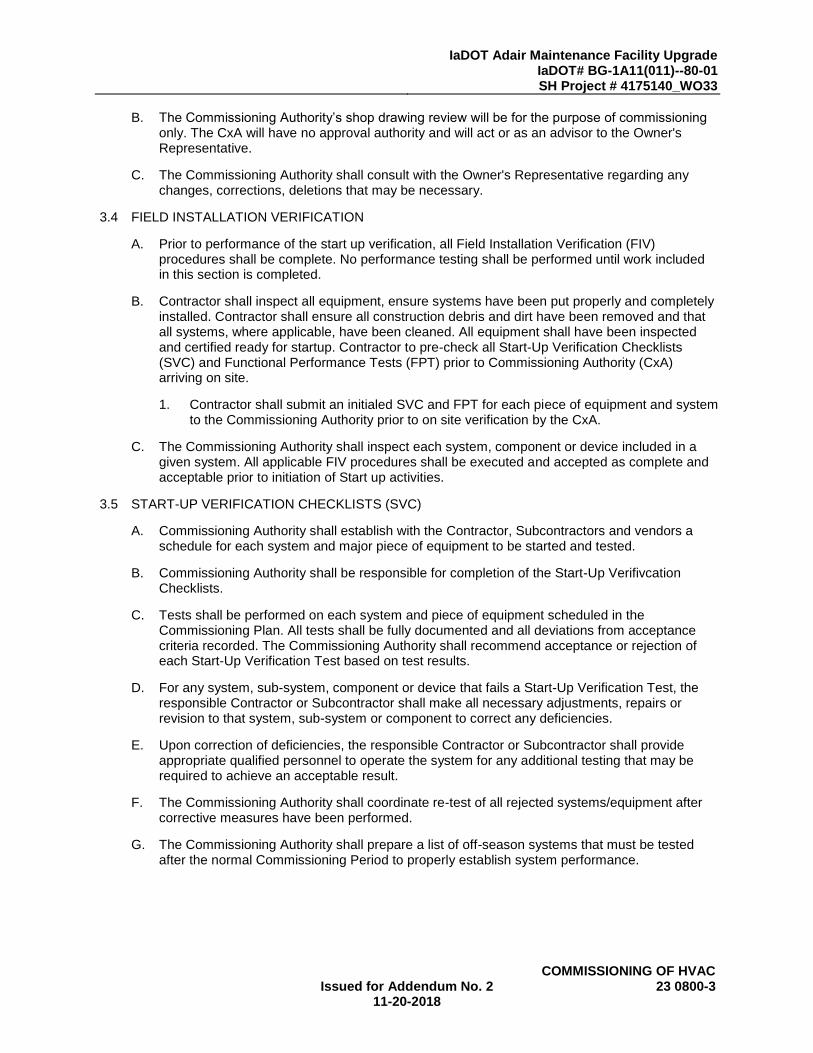
B. The Commissioning Authority’s shop drawing review will be for the purpose of commissioning only. The CxA will have no approval authority and will act or as an advisor to the Owner's Representative.
C. The Commissioning Authority shall consult with the Owner's Representative regarding any changes, corrections, deletions that may be necessary.
3.4 FIELD INSTALLATION VERIFICATION
A. Prior to performance of the start up verification, all Field Installation Verification (FIV) procedures shall be complete. No performance testing shall be performed until work included in this section is completed.
B. Contractor shall inspect all equipment, ensure systems have been put properly and completely installed. Contractor shall ensure all construction debris and dirt have been removed and that all systems, where applicable, have been cleaned. All equipment shall have been inspected and certified ready for startup. Contractor to pre-check all Start-Up Verification Checklists (SVC) and Functional Performance Tests (FPT) prior to Commissioning Authority (CxA) arriving on site.
1. Contractor shall submit an initialed SVC and FPT for each piece of equipment and system to the Commissioning Authority prior to on site verification by the CxA.
C. The Commissioning Authority shall inspect each system, component or device included in a given system. All applicable FIV procedures shall be executed and accepted as complete and acceptable prior to initiation of Start up activities.
3.5 START-UP VERIFICATION CHECKLISTS (SVC)
A. Commissioning Authority shall establish with the Contractor, Subcontractors and vendors a schedule for each system and major piece of equipment to be started and tested.
B. Commissioning Authority shall be responsible for completion of the Start-Up Verifivcation Checklists.
C. Tests shall be performed on each system and piece of equipment scheduled in the Commissioning Plan. All tests shall be fully documented and all deviations from acceptance criteria recorded. The Commissioning Authority shall recommend acceptance or rejection of each Start-Up Verification Test based on test results.
D. For any system, sub-system, component or device that fails a Start-Up Verification Test, the responsible Contractor or Subcontractor shall make all necessary adjustments, repairs or revision to that system, sub-system or component to correct any deficiencies.
E. Upon correction of deficiencies, the responsible Contractor or Subcontractor shall provide appropriate qualified personnel to operate the system for any additional testing that may be required to achieve an acceptable result.
F. The Commissioning Authority shall coordinate re-test of all rejected systems/equipment after corrective measures have been performed.
G. The Commissioning Authority shall prepare a list of off-season systems that must be tested after the normal Commissioning Period to properly establish system performance.

IaDOT Adair Maintenance Facility Upgrade IaDOT# BG-1A11(011)--80-01
SH Project # 4175140_WO33
COMMISSIONING OF HVAC 23 0800-4 Issued for Addendum No. 2
11-20-2018
3.6 FUNCTIONAL PERFORMANCE TESTING (FPT)
A. The Commissioning Authority shall conduct all Functional Performance Testing. The Contractor or Subcontractor responsible for the commissioned system shall provide appropriate qualified personnel to operate the system being tested under the supervision of the Commissioning Authority.
B. Equipment, systems, sub-systems, and components shall be tested and evaluated for conformance with the performance requirements outlined in the Basis of Design Document, the Functional Performance Test (FPT) protocols, and the Contract Documents. All testing and balancing and Start-Up Verification Tests must be complete for all systems before the FPT can begin unless directed otherwise by the CxA.
C. Tests shall be performed on each system scheduled in the Commissioning Plan. All tests shall be fully documented and all deviations from acceptance criteria recorded. The Commissioning Authority shall recommend acceptance or rejection of each Functional Performance Test based on test results.
1. Multiple identical pieces of non-critical equipment may be functionally tested using a sampling strategy.
a. A minor size or capacity difference does not constitute a difference. Major application differences or sequence of operation differences in similar equipment voids their commonality.
2. No sampling is allowed by the Contractor or Subcontractor in System Verification Checklists.
3. The sampling strategy to be followed for this project is a 20% Sampling/10% Failure Method.
a. Commissioning Authority shall randomly test 20% of each group of similar equipment. If there are less than three (3) units in a group, all units of that group shall be tested. This represents the first sample 20%.
b. If 10% of the units of the first sample fail their respective Functional Performance Test (FPT), the CxA shall test a second random 20% sample.
c. If 10% of the second sample fails the FPT’s, Commissioning Authority shall test all remaining units in the group.
d. If at any point during testing there are frequent failures occurring, and the testing is moving towards more troubleshooting than verification, the Commissioning Authority shall stop the testing and ask the responsible Contractor or Subcontractor to perform and document a checkout of the units remaining for functionality prior to continuation of the Functional Performance Testing.
D. For any system, sub-system or component deemed unacceptable as a result of the appropriate Functional Performance Test, the responsible Contractor or Subcontractor shall make all necessary adjustments, repairs or revision to that system, sub-system or component to correct any deficiencies.
E. Corrections made during functional performance testing are generally prohibited to avoid consuming the time of personnel waiting for the test but not involved in the correction. Exceptions will be allowed at the discretion of the Commissioning Authority if the cause of the failure is obvious and the corrective action can be made in less than ten minutes. If corrections are made under this exception the failure and correction will be noted on the functional performance test forms.

IaDOT Adair Maintenance Facility Upgrade IaDOT# BG-1A11(011)--80-01
SH Project # 4175140_WO33
COMMISSIONING OF HVAC Issued for Addendum No. 2
11-20-2018 23 0800-5
F. Upon correction of deficiencies, the responsible Contractor or Subcontractor shall provide appropriate qualified personnel to operate the system for any additional testing that may be required to achieve an acceptable result.
3.7 RECORD DRAWING VERIFICATION
A. The Commissioning Authority shall review all Record Drawings for general conformance with the constructed condition.
B. Review all documentation of systems and components and compare to actual on-site operation and hardware.
C. Review all Operation and Maintenance manual data submitted for completeness and accuracy.
D. Verify to the Contractor and the Owner's Representative that all system documentation is current.
3.8 OWNER TRAINING
A. Upon completion of training, the Commissioning Authority shall include verification of training in the Final Commissioning Report.
3.9 SYSTEM COMMISSIONING FINAL REPORT
A. The Commissioning Report shall include as a minimum the following data:
1. Documentation of all checklists completed in the installation verification.
2. Documentation of all tests performed, initial rejected tests and final acceptance tests, of all work performed during the start-up function.
3. All uncorrectable deviations from established performance criteria.
3.10 OPERATIONS AND MAINTENANCE MANUALS
A. The Commissioning Authority shall review the Operations and Maintenance Manuals and support documentation as part of this project. The documentation should include:
1. System Descriptions, Operating Conditions and Setpoint Parameters for each commissioned system.
2. Equipment and Systems installation, Operation and Maintenance Data Sheets.
3. Standard Operating Procedure for all commissioned systems and components including start up. Normal operation, shut down and emergency procedures.
4. Preventative Maintenance Procedure for all critical systems and components.
B. The Contractor shall coordinate assembly of all appropriate equipment and system data sheets by installing contractors, subcontractors and suppliers.
C. The Commissioning Authority shall be responsible for final review of O&M Manuals, operating procedures and preventative maintenance procedures so that this data can be used effectively by the operations and maintenance personnel.
END OF SECTION

IaDOT Adair Maintenance Facility Upgrade IaDOT# BG-1A11(011)--80-01
SH Project # 4175140_WO33
COMMISSIONING OF HVAC 23 0800-6 Issued for Addendum No. 2
11-20-2018

E
E
E
E
E
E
E
E
E
E
E
E
E
E
E
E
E
E
E
E
E
E
E
EE
E
E
E
E
E
E
E
E
E
E
E
E
E
E
E
E
E
E
E
1 2 3 4 5B C D FA
4
1
1e
-2
Ae AA CC
2
3
2e
Be
-1
BB
PANEL A
PANEL B
PANEL MDP
PANEL D
OHD-1
CORD REEL
OHD-1
CORD REEL
OHD-1
OHD-1
2 TON HOIST
RELOCATEDHOTSY
EWC
F-2
D-20
D-20
D-1,3
D-2,4 D-6,8
D-13,15
PANEL C
2HP OR LOWER
GFI
400ADISCONNECT
CU-1
C-5
C-7
SF-1
EF-6
EF-1
EF-2
SF-2
EF-7
EF-8
EF-3
SF-3
SF-4
EF-4
EF-10
EF-9
C-10
C-12C-13
C-14
C-14
S-1
S-2
S-1
C-19
C-27,29
C-27,29
C-20,22
C-21
C-20,22
D-18
D-17
RH1-1
RH1-4
VP-1VP-2
RH2-1
D-22
ERV-1
D-26
D-30
D-14,16
C-1
C-16
C-24,26
PANEL S
C-15
HVAC CONTROLS
S-1
THIS IS REUSED, DISCONNECT AND RECONNECT
C-11
C-3
POWER FOR LOW VOLTAGE TRANSFORMER
HVAC CONTROLS
C-27,29
F-1
WPGFI
WPGFI
WPGFI
WPGFI
WPGFI
WPGFI
WPGFI
WPGFI
WPGFI
WPGFI
WPGFI
WPGFI
WPGFI
WPGFI
WPGFI
WPGFI
E10(TYP.)
WPGFI
WPGFI
D-30
D-5,7
WPGFI
D-26
D-34
D-34
D-32
D-32
OHD-1
OHD-1
D-10,12
D-9,11
D-23,25
WPGFI
WPGFI
WPGFI
C-9
HVAC CONTROLS
C-20,22
CORAYVAC CONTROL PANEL
HVAC CONTROLSRH2-2
RH1-3
RH1-2
GWH-2
CO/NO2 CONTROL PANEL
E15E15
D-19,21
D-19,21
D-19,21
MAU-1
D-23,25
D-23,25
HVAC CONTROLS
CORAYVAC CONTROL PANEL
200ADISCONNECT
FACP
GENANNUN
S-3
E16
E17
D-24
D-28
200A DISCONNECT
D-24
D-22
C-6
E19
E18
C-1
E20
E20
D-24
D-24
D-22
D-22D-22
D-22
WPGFI
WPGFI
2
ADD
2
ADD
2
ADD2
ADD
2
ADD
2
ADD
2
ADD
2
ADD
2
ADD
E21
Ae
2e
C-8
GWH-1C-23,25
Printe
d:
Iow
a | Illi
nois
| India
na
DR
AW
N:
AP
PR
OV
ED
:
ISS
UE
D F
OR
:
DA
TE
:
FIE
LD
BO
OK
:
PR
OJE
CT
NO
:
CLIE
NT
NO
:
4
A B D E FC
3
2
1
A B D E FC
4
3
2
1
4125 W
esto
wn P
kw
y, S
uite 1
00 | W
est D
es M
oin
es, IA
50266
515.2
23.8
104
| F
AX
: 5
15.2
23.6
022
| w
ww
.sh
ive-h
attery
.com
Autodesk Revit 2017
2018-1
1-1
9 1
6:0
1:0
3
C:\
Shiv
e\R
evit_Local_
2017\4
175140-P
ME
-Cent_
jmhahn.r
vt
IaD
OT
AD
AIR
MA
INT
EN
AN
CE
GA
RA
GE
FA
CIL
ITY
UP
GR
AD
E
IDO
T
300
HIL
LC
RE
ST
RD
. | A
DA
IR, IO
WA
E201
FIR
ST
FLO
OR
PO
WE
R P
LA
NC
ON
ST
RU
CT
ION
DO
CU
ME
NT
S
41
75
14
0
BG
-1A
11
(01
1)-
-80
-01
NE
S
JM
H
20
18
-09
-26
0TRUE NORTH
NORTHPLAN
1/8" = 1'-0"4A
FIRST FLOOR POWER PLAN12'
0TRUE NORTH
NORTHPLAN
1/8" = 1'-0"2B
SECOND FLOOR POWER PLAN12'
KEYNOTE LEGEND
KEY NOTE
E10 WEATHERPROOF OUTLETS SHALL HAVE A COVER.
E15 EMERGENCY STOP PUSH BUTTON FOR HOIST.
E16 EMERGENCY STOP PUSH BUTTON FOR GENERATOR.
E17 REMOTE START PUSH BUTTON FOR HOTSY.
E18 PROVIDE CONNECTION TO SHUTOFF VALVE ON BACKFLOWPREVENTER. PROVIDE DISCONNECTING MEANS FOR VALVE.
E19 PROVIDE POWER FROM TIME CLOCK, PROVIDED BY ERVMANUFACTURER. COORDINATE LOCATION OF TIME CLOCK WITHMANUFACTURER.
E20 PROVIDE DISCONNECT FOR CORAYVAC CONTROL PANEL.
E21 CEILING MOUNTED GFI RECEPTACLE. INSTALL NEAR RADIANTHEATER. COORDINATE EXACT LOCATION WITH FINAL HEATERPLACEMENT. TYPICAL OF ALL RADIANT HEATERS.
AD
D2
20
18-1
1-2
0A
DD
EN
DU
M 2

E
E
E
E
E
E
E
E
E
E
E
E
E
E
E
E
E
E
E
E
E
E
E
E
E
E
E
E
E
E
E
E
E
E
E
E
E
E
E
E
E
E
E
E
E
E
E
E
E
E
E
1 2 3 4 6 78B C D FA
4
1
1e
-2
Ae AA CC
2
3
2e
Be
-1
BB
F-1
CU-1
C-2,4
C-16
C-24,26
OHD-1 OHD-1
OHD-1
CORD REEL
OHD-1
2 TON HOIST
CORD REEL
RELOCATEDHOTSY
VP-2A
RH2A-2
RH1A-5
OHD-1
OHD-1
RH1A-1
RH1A-6
HIDE EF-10
EF-11AEF-4A
SF-4ASF-11A
RH1A-2
RH1A-3
EF-9A
VP-1A
RH2A-1
D-1,3
D-26
D-5,7
D-9,11
D-18,20
D-24
D-31
D-22
D-22
D-2,4
D-26
D-6,8
D-17,19
D-29
D-10,12
D-22
CORD REEL
CORD REELD-26
D-26
OHD-1
OHD-1
D-13,15
D-14,16
D-25,27
D-32
D-32
D-34
D-30
D-30
D-36
D-36
C-12C-14
C-15
C-13
S-1
S-2
S-1
S-1
C-3
C-5
C-11
C-10
C-7
C-27,29
C-1
C-19
C-27,29
C-27,29
C-20,22
C-20,22
C-21
C-14
WPGFI
WPGFI WP
GFI
WPGFI
WPGFI
400ADISCONNECT
200ADISCONNECT
GENANNUN
FACP
S-3
E16
E17
C-20,22
HVAC CONTROLS
POWER FOR LOW VOLTAGE TRANSFORMER
CO/NO2 CONTROL PANEL
HVAC CONTROLS
HVAC CONTROLS
PANEL S
THIS IS REUSED, DISCONNECT AND RECONNECT.
EWC
PANEL C
PANEL B
PANEL A
200A DISCONNECT
PANEL MDP
PANEL D
D-25,27
D-25,27
HVAC CONTROLS
CORAYVAC CONTROL PANEL
CORAYVAC CONTROL PANEL
D-36
D-24
HVAC CONTROLS
D-21,23
D-21,23D-21,23
D-21,23
D-21,23
E15
E15
D-22
D-28GWH-2
2HP OR LOWER
C-6
C-1
E19
E18
ERV-1
EF-3
SF-3
SF-2
EF-2
EF-7
EF-8
EF-1
EF-6
SF-1E20
E20
WPGFI
WPGFI
D-22
D-22
D-22
D-22
D-24
D-24
2
ADD
2
ADD
RH1A-42
ADD2
ADD
2
ADD2
ADD
2
ADD
2
ADD
E21
Printe
d:
Iow
a | Illi
nois
| India
na
DR
AW
N:
AP
PR
OV
ED
:
ISS
UE
D F
OR
:
DA
TE
:
FIE
LD
BO
OK
:
PR
OJE
CT
NO
:
CLIE
NT
NO
:
4
A B D E FC
3
2
1
A B D E FC
4
3
2
1
4125 W
esto
wn P
kw
y, S
uite 1
00 | W
est D
es M
oin
es, IA
50266
515.2
23.8
104
| F
AX
: 5
15.2
23.6
022
| w
ww
.sh
ive-h
attery
.com
Autodesk Revit 2017
2018-1
1-1
9 1
6:0
2:0
3
C:\
Shiv
e\R
evit_Local_
2017\4
175140-P
ME
-Cent_
jmhahn.r
vt
IaD
OT
AD
AIR
MA
INT
EN
AN
CE
GA
RA
GE
FA
CIL
ITY
UP
GR
AD
E
IDO
T
300
HIL
LC
RE
ST
RD
. | A
DA
IR, IO
WA
E201A
FIR
ST
FLO
OR
PO
WE
R P
LA
N -
ALT
ER
NA
TE
CO
NS
TR
UC
TIO
N D
OC
UM
EN
TS
41
75
14
0
BG
-1A
11
(01
1)-
-80
-01
Ap
pro
ve
r
Au
thor
20
18
-09
-26
0TRUE NORTH
NORTHPLAN
1/8" = 1'-0"4A
FIRST FLOOR POWER PLAN - NORTH ALTERNATE12'
AD
D2
20
18-1
1-2
0A
DD
EN
DU
M 2
KEYNOTE LEGEND
KEY NOTE
E15 EMERGENCY STOP PUSH BUTTON FOR HOIST.
E16 EMERGENCY STOP PUSH BUTTON FOR GENERATOR.
E17 REMOTE START PUSH BUTTON FOR HOTSY.
E18 PROVIDE CONNECTION TO SHUTOFF VALVE ON BACKFLOWPREVENTER. PROVIDE DISCONNECTING MEANS FOR VALVE.
E19 PROVIDE POWER FROM TIME CLOCK, PROVIDED BY ERVMANUFACTURER. COORDINATE LOCATION OF TIME CLOCK WITHMANUFACTURER.
E20 PROVIDE DISCONNECT FOR CORAYVAC CONTROL PANEL.
E21 CEILING MOUNTED GFI RECEPTACLE. INSTALL NEAR RADIANTHEATER. COORDINATE EXACT LOCATION WITH FINAL HEATERPLACEMENT. TYPICAL OF ALL RADIANT HEATERS.
2
ADD
Printe
d:
Iow
a | Illi
nois
| India
na
DR
AW
N:
AP
PR
OV
ED
:
ISS
UE
D F
OR
:
DA
TE
:
FIE
LD
BO
OK
:
PR
OJE
CT
NO
:
CLIE
NT
NO
:
4
A B D E FC
3
2
1
A B D E FC
4
3
2
1
4125 W
esto
wn P
kw
y, S
uite 1
00 | W
est D
es M
oin
es, IA
50266
515.2
23.8
104
| F
AX
: 5
15.2
23.6
022
| w
ww
.sh
ive-h
attery
.com
Autodesk Revit 2017
2018-1
1-1
9 1
6:0
1:0
6
C:\
Shiv
e\R
evit_Local_
2017\4
175140-P
ME
-Cent_
jmhahn.r
vt
IaD
OT
AD
AIR
MA
INT
EN
AN
CE
GA
RA
GE
FA
CIL
ITY
UP
GR
AD
E
IDO
T
300
HIL
LC
RE
ST
RD
. | A
DA
IR, IO
WA
E600
ELE
CT
RIC
AL
SC
HE
DU
LE
SC
ON
ST
RU
CT
ION
DO
CU
ME
NT
S
41
75
14
0
BG
-1A
11
(01
1)-
-80
-01
NE
S
JM
H
20
18
-09
-26
Notes:
SPEC 21288 VA 100.00% 21288 VA TOTAL EST. DEMAND... 151.7 A
RCPT 4500 VA 100.00% 4500 VA TOTAL CONN. CURRENT: 149.2 A
MOTORS 6888 VA 108.54% 7476 VA TOTAL EST. DEMAND: 36399.9 VA
LITES 3565 VA 100.00% 3565 VA TOTAL CONN. LOAD: 35813.4 VA
Load ClassificationConnected Load
(VA)Demand Factor
EstimatedDemand (VA)
PANEL TOTALS
TOTAL AMPS: 151.5 A 146.9 A
TOTAL LOAD: 18182.6 VA 17631.7 VA
41 42
39 40
37 38
35 36
33 0.0 / 0.9 34 20 A 1 W. WASHBAY RCPT
NIGHT LIGHTING 1 20 A 31 0.8 / 0.9 32 20 A 1 E. WASHBAY RCPT
WASHBAY LIGHTING 1 20 A 29 1.2 / 0.5 30 20 A 1 S. STORAGE RCPT
STORAGE LIGHTING 1 20 A 27 1.6 / 0.0 28 20 A 1 -- GWH-2
-- -- -- -- 25 2.6 / 1.1 26 20 A 1 N. STORAGE RCPT
EF-5 & MAU-1 2 40 A 23 2.6 / 0.9 24 20 A 1 WASHBAY RADIANT HEAT
-- -- -- -- 21 1.9 / 1.5 22 20 A 1 STORAGE RADIANT HEAT
EF-4 &SF-4 2 30 A 19 1.9 / 1.2 20 20 A 1 CORD REELS
WASHBAY EXHAUST FAN 1 20 A 17 0.4 / 0.3 18 20 A 1 STORAGE EXHAUST FAN
-- -- -- -- 15 1.4 / 3.0 16 -- -- -- --
2 TON HOIST 2 20 A 13 1.4 / 3.0 14 20 A 2 HOTSY
-- -- -- -- 11 0.3 / 0.3 12 -- -- -- --
E. WASHBAY OHD 2 20 A 9 0.3 / 0.3 10 20 A 2 W. WASHBAY OHD
-- -- -- -- 7 0.7 / 0.7 8 -- -- -- --
S.E. STORAGE OHD 2 20 A 5 0.7 / 0.7 6 20 A 2 S.W. STORAGE OHD
-- -- -- -- 3 0.7 / 0.7 4 -- -- -- --
N.E.STORAGE OHD 2 20 A 1 0.7 / 0.7 2 20 A 2 N.W. STORAGE OHDL
OA
D
CO
DE
PO
LE
BK
R
CK
T # A
KVAB
KVA
CK
T #
BK
R
PO
LE
CO
DE
LO
AD
FED... FEED:
ROOM: STORAGE BAYS 110 ENCLOSURE: NEMA 1
CODE: L=LIGHTING, R=RECEPTACLES, M=MOTORS, K=KITCHEN MOUNTING: SURFACE
D120/240 Single 1 3 200 AMPS 200 A
10,000 AMPSSYMMETRICAL
BRANCH PANEL NAME VOLTAGE PHASE WIRE BUS SIZE MAIN OCP AIC RATING
Notes:
SPEC 9222 VA 102.79% 9480 VA TOTAL EST. DEMAND... 116.4 A
RCPT 7200 VA 100.00% 7200 VA TOTAL CONN. CURRENT: 112.9 A
MOTORS 9504 VA 106.19% 10092 VA TOTAL EST. DEMAND: 27935.9 VA
LITES 573 VA 100.00% 573 VA TOTAL CONN. LOAD: 27092.8 VA
Load ClassificationConnected Load
(VA)Demand Factor
EstimatedDemand (VA)
PANEL TOTALS
TOTAL AMPS: 117.0 A 108.8 A
TOTAL LOAD: 14037.1 VA 13055.9 VA
41
39
37
35
33
31
-- -- -- -- 29 1.7 / 0.0 -- -- --
EF-2, SF-2, & HVAC CONTROLS 2 20 A 27 1.7 / 0.0 2 -- SITE LIGHTING
-- -- -- -- 25 0.8 / 1.9 -- -- --
FT-1 2 20 A 23 0.8 / 1.9 2 CU-1
EF-8 1 20 A 21 0.3 / 2.8 -- -- --
EF-7 1 20 A 19 0.3 / 2.8 2 EF-3 & SF-3
N.W. OFFICE/RR LIGHTING 1 20 A 17 0.3 / 0.3 1 LITES OFFICES 26
RCPT PARTS/MECH ROOM 109 1 20 A 15 1.4 / 1.2 1 F-1
RCPT OFFICES 26 1 20 A 13 1.1 / 0.4 1 RCPT OFFICES EAST
RCPT MEN 22 1 20 A 11 0.2 / 1.1 1 RCPT OFFICES EAST
CO/NO2 CONTROL PANEL 1 20 A 9 0.0 / 1.4 1 RCPT SENIOR OFFICE 25
RCPT SUPERVISOR 24 1 20 A 7 1.4 / 0.2 1 HWCP
WATER COOLER 1 20 A 5 0.7 / 0.0 1 AUTO-OFF BACKFLOW
LV XFMR RESTROOMS 1 20 A 3 0.0 / 0.3 -- -- --
ERV-1 & CONTROLS 1 20 A 1 2.4 / 0.3 2 F-2
LO
AD
CO
DE
PO
LE
BK
R
CK
T #
A B
PO
LE
CO
DE
LO
AD
FED... FEED:
ROOM: Existing Storage Bays 106 ENCLOSURE: NEMA 1
CODE: L=LIGHTING, R=RECEPTACLES, M=MOTORS, K=KITCHEN MOUNTING: SURFACE
C120/240 Single 1 3 100 AMPS 100 A
10,000 AMPSSYMMETRICAL
BRANCH PANEL NAME VOLTAGE PHASE WIRE BUS SIZE MAIN OCP AIC RATING
1. CONTRACTOR SHALL PROVIDE AND INSTALL UNI-STRUT AS REQUIRED FOR MOUNTING.
SCHEDULE NOTES:
A. CONTRACTOR SHALL REFER TO SPECIFICATIONS REGARDING PROVIDING ADDITIONAL SPARE LAMPS, LENSES, AND GLOBES.
B. WHERE "APPROVED EQUAL" IS LISTED IN THE MANUFACTURER COLUMN, FIXTURES MUST BE SUBMITTED AS A SUBSTITUTION FOR APPROVAL PRIOR TO BID SUBMISSION.
GENERAL NOTES:
PS-NBF: PROGRAMMED START NORMAL BALLAST FACTOR (.88 BF) PS-HBF: PROGRAMMED START HIGH BALLAST FACTOR (1.0 BF) DHD-NBF: DIMMING BALLAST, 0-10 VDC
BALLAST TYPES:
LIGHTING FIXTURE SCHEDULE
TYPE Description LENS-LOUVER MOUNTING LAMPBALLAST/DRIVER VOLT WATT BASIS OF DESIGN
APPROVEDEQUIVALENT NOTE
E1 CONTEMPORARY LED SINGLE FACED EXIT SIGN,RED LETTERS, AND CHEVRON ARROWS ASSHOWN ON PLANS.
--- UNIVERSAL LED LEDDRIVER
120 V 5 W LITHONIA OR APPROVEDEQUIVALENT
E2 INDUSTRIAL LED SINGLE FACED EXIT SIGN, REDLETTERS, AND CHEVRON ARROWS AS SHOWN ONPLANS.
--- UNIVERSAL LED LEDDRIVER
120 V 5 W LIGHT ALARMSXV12E
OR APPROVEDEQUIVALENT
L1 2' X 4' LED FLAT PANEL TROFFER, ALUMINUMHOUSING
FROSTEDPOLYCARBONATE
DIFFUSER
RECESSED LED, 3000LUMENS,
4000K
LEDDRIVER
120 V 26 W LITHONIA EPANL OR APPROVEDEQUIVALENT
L2 2' X 2' LED FLAT PANEL TROFFER, ALUMINUMHOUSING
FROSTEDPOLYCARBONATE
DIFFUSER
RECESSED LED, 2100LUMENS,
4000K
LEDDRIVER
120 V 18 W LITHONIA EPANL OR APPROVEDEQUIVALENT
L3 15" X 44" INDUSTRIAL HIGH BAY SEMI-DIFFUSEACRYLIC
CHAINSUSPEND
CORD & PLUG
LED, 18,000LUMENS,
4000K, 70 CRI
LEDDRIVER
120 V 146 W LITHONIA IBH OR APPROVEDEQUIVALENT
1
L4 6.75" X 100" INDUSTRIAL HIGH BAY SEMI-DIFFUSEACRYLIC
CHAINSUSPEND
CORD & PLUG
LED, 12,300LUMENS,
4000K, 70 CRI
LEDDRIVER
120 V 144 W AZZ FPF LED OR APPROVEDEQUIVALENT
1
S1 EXTERIOR WALL BRACKET WEATHERPROOF LEDFIXTURE, 18"W x 9"D x 7"H, ALUMINUM HOUSING,FORWARD THROW DISTRIBUTION
--- WALL LED, 3000,LUMENS,
4000K
LEDDRIVER
120 V 30 W LITHONIA WST LED OR APPROVEDEQUIVALENT
4. PROVIDE DISCONNECT FOR EQUIPMENT.
3. EQUIPMENT CIRCUITED TOGETHER TO SHARE DISCONNECT BEFORE CONTROL PANEL. DISCONNECT PROVIDED BY E.C.
2. POWERED THROUGH MANUFACTURER PROVIDED TIMECLOCK.
1. PROVIDE STARTER FOR EQUIPMENT.
NOTES:
PWE = PROVIDED WITH EQUIPMENT MAG=MAGNETIC STARTER
SPSW = SINGLE POLE SWITCH F = FUSED NF = NON-FUSED REC = RECEPTACLE MMS=MANUAL MOTOR STARTER
FLA = FULL LOAD AMPS MCA = MIN. CIRCUIT AMPS C/B = CIRCUIT BREAKER VFD = VARIABLE FREQUENCY DRIVE WP=WEATHERPROOF
KEY:
VP-2 VACUUM PUMP 120/1 4.8 3/4" C,2#12,1#12 4
VP-1 VACUUM PUMP 120/1 6.6 3/4" C,2#12,1#12 4
RH2-2 RADIANT HEATER 120/1 0.3 3/4" C,2#12,1#12
RH2-1 RADIANT HEATER 120/1 0.3 3/4" C,2#12,1#12
RH1-4 RADIANT HEATER 120/1 0.3 3/4" C,2#12,1#12
RH1-3 RADIANT HEATER 120/1 0.3 3/4" C,2#12,1#12
RH1-2 RADIANT HEATER 120/1 0.3 3/4" C,2#12,1#12
RH1-1 RADIANT HEATER 120/1 0.3 3/4" C,2#12,1#12
GWH-2 GAS WATER HEATER 120/1 2.0 20/1 3/4" C,2#12,1#12 REC
GWH-1 GAS WATER HEATER 120/1 5 20/1 3/4" C,2#12,1#12 SPSW
SF-4 SUPPLY FAN 1 HP 240/1 8 3/4" C,2#10,1#12 NF 3
SF-3 SUPPLY FAN 3/4 HP 240/1 6.9 3/4" C,2#12,1#12 NF 3
SF-2 SUPPLY FAN 3/4 HP 240/1 6.9 3/4" C,2#12,1#12 NF 3
SF-1 SUPPLY FAN 3/4 HP 240/1 6.9 3/4" C,2#12,1#12 NF 3
MAU-1 MAKEUP AIR UNIT 3 HP 240/1 17 3/4" C,2#10,1#12 NF 3
FT-1 FIN-TUBE HEAT 1.5kW 240/1 6.3 20/2 3/4" C,2#12,1#12
F-2 GAS FURNACE - EXISTING 120/1 20/1 3/4" C,2#12,1#12
F-1 GAS FURNACE 1/2 HP 120/1 9.8 20/1 3/4" C,2#12,1#12
ERV-1 ENERGY RECOVERY VENTILATOR 1/2 HP 120/1 9.8 20/1 3/4" C,2#10,1#12 2
EF-10 EXHAUST FAN 1/4 HP 120/1 3.6 20/1 3/4" C,2#12,1#12
EF-9 EXHAUST FAN 1/10 HP 120/1 2.2 20/1 3/4" C,2#12,1#12
EF-8 EXHAUST FAN 1/10 HP 120/1 2.2 20/1 3/4" C,2#12,1#12
EF-7 EXHAUST FAN 1/10 HP 120/1 2.2 20/1 3/4" C,2#12,1#12
EF-6 EXHAUST FAN 1/4 HP 120/1 3.6 20/1 3/4" C,2#12,1#12
EF-5 EXHAUST FAN 3/4 HP 240/1 6.9 3/4" C,2#12,1#12 1, 3
EF-4 EXHAUST FAN 1 HP 240/1 8 3/4" C,2#10,1#12 NF 3
EF-3 EXHAUST FAN 3/4 HP 240/1 6.9 3/4" C,2#12,1#12 NF 3
EF-2 EXHAUST FAN 3/4 HP 240/1 6.9 3/4" C,2#12,1#12 NF 3
EF-1 EXHAUST FAN 3/4 HP 240/1 6.9 3/4" C,2#12,1#12 NF 3
CU-1 CONDENSING UNIT 240/1 16 3/4" C,2#10,1#12
PLANMARK
DESCRIPTION HP/KW VOLT/PH FLA C/B CONDUIT, WIRE SIZE DISC. NOTES
EQUIPMENT SCHEDULE
5. PROVIDE (1) 600A 2P DISTRIBUTION BREAKER FOR PANEL M.
4. REFER TO SECTIONS 26 3600 FOR ADDITIONAL REQUIREMENTS.
3. INCLUDE OPEN TRANSITION MAINTENANCE BYPASS SWITCH WITHIN ENCLOSURE.
2. 600A 2P MAIN BREAKER.
1. SERVICE ENTRANCE RATED.AUTOMATIC ASCO 7000 SERIES 240 1 600 60 NEMA 4X 1, 2, 3, 4, 5
TYPEMANUFACTURE
RMODEL VOLTS PHASE AMPS FREQ. SCCR
ENCLOSURE
RATINGNOTES
AUTOMATIC TRANSFER SWITCH
3. GENERATOR TO BE INITIALLY FUELED BY NATURAL GAS ONLY, LP CAPABILITY IS FOR FUTURE USE.
2. REFER TO SECTION 26 3213 FOR ADDITIONAL REQUIREMENTS.
1. ACCEPTABLE MANUFACTURERS: CATEPILLAR, KOHLER, GENERAC.
NOTES:
120/240 1 600 60 100KW NATURAL GAS/LP 1, 2, 3
VOLTS PHASE AMPS FREQ.
NAMEPLATE
RATING FUEL NOTES
GENERATOR
Notes:
TOTAL EST. DEMAND... 0.0 A
TOTAL CONN. CURRENT: 0.0 A
TOTAL EST. DEMAND: 0.0 VA
TOTAL CONN. LOAD: 0.0 VA
Load ClassificationConnected Load
(VA)Demand Factor
EstimatedDemand (VA)
PANEL TOTALS
TOTAL AMPS: 0.0 A 0.0 A
TOTAL LOAD: 0.0 VA 0.0 VA
11 12
9 10
7 8
5 6
-- -- -- -- 3 0.0 / 0.0 4 -- -- -- --
PANEL MDP -- 2 400 A 1 0.0 / 0.0 2 200 A 2 -- PANEL D
LO
AD
CO
DE
PO
LE
BK
R
CK
T # A
KVAB
KVA
CK
T #
BK
R
PO
LE
CO
DE
LO
AD
FED... FEED:
ROOM: ENCLOSURE: NEMA 1
CODE: L=LIGHTING, R=RECEPTACLES, M=MOTORS, K=KITCHEN MOUNTING: SURFACE
N120/240 Single 1 3 600 AMPS 600 A
22,000 AMPSSYMMETRICAL
BRANCH PANEL NAME VOLTAGE PHASE WIRE BUS SIZE MAIN OCP AIC RATING
1. EXISTING BREAKERS ARE FROM PREVIOUS PANELS THAT ARE TO BE DEMOLISHED. REINSTALL THEM INTO PANEL S.
Notes:
TOTAL EST. DEMAND... 9.6 A
TOTAL CONN. CURRENT: 8.7 A
SPEC 0 VA 0.00% 0 VA TOTAL EST. DEMAND: 2295.0 VA
MOTORS 2088 VA 109.91% 2295 VA TOTAL CONN. LOAD: 2088.0 VA
Load ClassificationConnected Load
(VA)Demand Factor
EstimatedDemand (VA)
PANEL TOTALS
TOTAL AMPS: 17.4 A 0.0 A
TOTAL LOAD: 2088.0 VA 0.0 VA
29 30
27 28
25 26
23 24
21 22
-- -- -- -- 19 0.0 / 0.0 20
EXISTING -- 2 20 A 17 0.0 / 0.0 18
-- -- -- -- 15 0.0 / 0.0 16 -- -- -- --
EXISTING -- 2 40 A 13 0.0 / 0.0 14 20 A 2 -- EXISTING
-- -- -- -- 11 0.0 / 0.0 12 20 A 1 -- EXISTING
EXISTING -- 2 30 A 9 0.0 / 0.0 10 20 A 1 -- EXISTING
EXISTING -- 1 30 A 7 0.0 / 0.0 8 20 A 1 -- EXISTING
EXISTING -- 1 15 A 5 0.0 / 0.0 6 20 A 1 -- EXISTING
FACP 1 20 A 3 0.0 / 0.0 4 20 A 1 -- EXISTING
EF-1 & SF-1 1 20 A 1 1.7 / 0.4 2 20 A 1 EF-6
LO
AD
CO
DE
PO
LE
BK
R
CK
T # A
KVAB
KVA
CK
T #
BK
R
PO
LE
CO
DE
LO
AD
FED... FEED:
ROOM: Existing Mechanics Bay... ENCLOSURE: NEMA 1
CODE: L=LIGHTING, R=RECEPTACLES, M=MOTORS, K=KITCHEN MOUNTING: SURFACE
S120/240 Single 1 3 100 AMPS 100 A
10,000 AMPSSYMMETRICAL
BRANCH PANEL NAME VOLTAGE PHASE WIRE BUS SIZE MAIN OCP AIC RATING
AD
D2
20
18-1
1-2
0A
DD
EN
DU
M 2
2
ADD
2
ADD

D3
M500
WomensRestroom
104
136 SF
MensRestroom
103
SupervisorOffice
102
SupportOffice
101
CU-1
F-1
VP-2
SD-A6ø
SD-A6ø
ERV-1
EG-D6x670EG-D
8x8210
OA UP TO GIH-1 EA UP TO GEH-1
8ø EA
10ø
10ø
EF-1
EF-6
SF-1
EF-2
EF-7
SF-2
EF-8
EF-3
SF-3
EF-4
EF-9
SF-4
EF-10
SG-B12x8225
DAMPER COUPLING
VP-1
RH1-1
RH1-4
RH2-1
EXISTING CONDENSTING UNIT TO REMAIN
SG-B12x8225
SG-B12x8225
SG-B12x8250
OA UP TO GIH-2 ON ROOF. MAINTAIN 10' MIN FROM EXHAUST/FLUE VENTS
Corridor
100
ExistingStorage
Bays
106
ExistingMechanics
Bay
105
FlexibleOffice
108
Parts/MechRoom
109
ExistingStorage
Bays
107
STORAGEBAYS
110
DRIVETHRU
WASH BAY
111
EXISTING RADIANT HEATING SYSTEM SHALL REMAIN
RELOCATE FURNACE AS REQUIRED
18x1114x814x118ø 8ø
SD-A6ø
14x6 SA UPTO FLOOR GRILLE
TO FLOOR GRILLE
14x6 SA UP
6ø
OFFICE AREA NOTES: 1. REMOVE AND REPLACE CEILINGS AS REQUIRED IN ALL OFFICE AREAS NOT RECEVING NEW CEILINGS TO INSTALL NEW DUCTWORK (TYP).SEE ARCH PLANS
2. ALL DIFFUSERS/GRILLES SHALL HAVE OPPOSED BLADE DAMPERS TO ALLOW FOR AIRFLOW BALANCING IN GYP CEILINGS.
M05
NEW OA INTAKE WITH MANUFACTURER'S VENT CAP
NEW OA INTAKE WITH MANUFACTURER'S VENT CAP
NEW OA INTAKE WITH MANUFACTURER'S VENT CAP
150 cfm
150 CFM
50 cfm
SD-A6ø
SD-A6ø CO
CO
CO
CO
2NO
2NO
2NO
CO
2NO
CO
CO
CO
2NOM09
M09
M09
M09
M09
M09
M09
M09
M09
M09
M09
M09
M09
75 cfm
75 cfm
NEW FAN CONTROL BOX TO CONTROL EF-1 AND SF-1
NEW FAN CONTROL BOX TO CONTROL EF-2 AND SF-2
NEW FAN CONTROL BOX TO CONTROL EF-3 AND SF-3
NEW FAN CONTROL BOX TO CONTROL EF-4 AND SF-4
NEW RADAINT HEAT CONTROL BOX
NEW RADAINT HEAT CONTROL BOX
100 CFM
M10
NEW OA INTAKE WITH MANUFACTURER'S VENT CAP
CO/NO2 CONTROL PANEL. COORDINATE WALL SPACE.
CO/NO2 RELAY PANEL. COORDINATE WALL SPACE.
RH2-2
PROVIDE SIDE SHIELDS ALONG EXTERIOR WALLS. SEE SPECIFICATIONS
MD05
16
x1
2
16
x1
2
RG-C24x12
12ø
EXPOSED ROUND DOUBLE WALL DUCTWORK. PRIMED FOR FIELD PAINTING. COLOR BY ARCH. SEE SPECS
16x12
M10
M10
300 CFM 300 CFM
A3
M500
MAU-1M
CONTRACTOR SHALL FABRICATE OA HOOD. SEE SECTION.
MIN
3'-0
"
REMOTE CONTROL PANEL FOR MAU
PROVIDE SPLASH SHIELDS IN WASH BAY. TYP. (SEE SPECS)
SD-E15x15500(TYP. 4)
SD-E15x151100(TYP. 4)
SD-E15x15775(TYP. 4)
SD-E15x151175(TYP. 4)
STROBE
NEW GAS DETECTION SENSOR. SEE DETAIL (TYP.)STROBE
STROBE STROBE
STROBE
STROBE
WEATHERPROOFSTROBE
STROBE
8x8
M
LOW LEAKAGE OA DAMPER SHALL BE POWERED THOUGH DIGITAL TIMECLOCK PROVIDED WITH ERV-1 TO CLOSE OA DURING UNOCCUPIED HOURS
M11
W/OBD
M12
M12
14x8 RA
10
x6
RG-C10x10150
W/OBD
RELOCATED FILTER RACK
14x8 RA UP
16x16 RA UP
8ø
6ø1
4x8 R
A
TYP. 2
10x6
BETWEEN EXISTING JOISTS
BETWEEN EXISTING JOISTS
EF-5
M01
T
T
RELOCATE EXISTING THERMOSTAT
T
T
RH1-3
RH1-3RH1-4
RH1-1RH1-2
RH1-2
T
RH2-1RH2-2 PROVIDE SPLASH
SHIELDS IN WASH
2
ADD
2
ADD
2
ADD
M05
M06
M06
2
ADD
1. LIGHT LINES INDICATE EXISTING PIPING, DUCTWORK, EQUIPMENT, ETC. TO REMAIN. BOLD LINES INDICATE PIPING, DUCTWORK, EQUIPMENT, ETC. TO BE INSTALLED THIS CONTRACT UNLESS NOTED OTHERWISE.
2. COORDINATE ROUGH-IN AND FINAL LOCATION OF DUCTWORK AND PIPING WITH LIGHTING, STRUCTURE, SPRINKLER, ETC. PROVIDE OFFSETS AND/OR EASEMENTS, OR RELOCATE AS REQUIRED TO AVOID CONFLICTS WITH WORK OF OTHER TRADES. DUCT DROP/RISES SHALL BE RADIUS ELBOWS AND BE AT A MAXIMUM ANGLE OF 45 DEGREES.
3. INSTALL MANUAL VOLUME DAMPERS IN ALL SUPPLY, RETURN, AND EXHAUST DUCT SYSTEMS AS REQUIRED FOR CONTROLLING AIR VOLUMES TO TRUNK DUCTS, BRANCH DUCTS, OUTLETS AND INLETS. CONTRACTOR SHALL INSTALL A COMPLETE SYSTEM OF DAMPERS AS REQUIRED FOR BALANCING AIR SYSTEMS.
4. BREAK CONNECTIONS ARE REQUIRED AT ALL MAJOR EQUIPMENT AND ALL PIPING ITEMS THAT REQUIRE REMOVAL FOR MAINTENANCE.5. DRAWINGS INDICATE APPROXIMATE ROUTING OF PIPING AND DUCTWORK AND DO NOT INCLUDE ALL OFFSETS, FITTINGS, VALVES, ETC. VERIFY
ROUTING AND CLEARANCES AND COORDINATE WITH OTHER TRADES PRIOR TO FABRICATION.6. CONTRACTOR SHALL PATCH/REPAIR ALL UNUSED OPENINGS AND MODIFIED FINISH SURFACES. PATCHING SHALL MATCH MATERIALS, FINISH, AND
TEXTURE OF ADJACENT SURFACES.7. INSTALL ALL RADIANT HEATING PER MANUFACTURER'S WRITTEN RECOMMENDATIONS AND MAINTAIN ALL REQUIRED CLEARANCES OF NEW AND
EXISTING EQUIPMENT.8. RADIANT HEATING REFLECTORS ARE NOT SHOWN ON DRAWINGS FOR CLARITY, CONTRACTOR SHALL FURNISH AND INSTALL REFLECTORS AS
SPECIFIED. PROVIDE AND INSTALL SIDE REFLECTORS WHERE BURNER TUBES ARE LOCATED WITHIN 4' OF AN EXTERIOR WALL FOR THE FIRST 60'DOWN STREAM OF A BURNER.
9. RADIANT TUBE LENGTHS SHOWN ARE APPROXIMATE. CONTRACTOR SHALL FIELD VERIFY ALL EQUIPMENT LOCATIONS AND LENGTHS PRIOR TO ORDREING.
10. RADIANT TUBE AND OA PIPE SHALL BE 4" UNLESS SHOWN OTHERWISE.11. CONTRACTOR SHALL TEST SYSTEM FOR PROPER VACUUM AT BRANCH END VENTS FOLLOWING INSTALLATION. MAKE ADJUSTMENTS AS NECESSARY
TO PROVIDE 2 1/2" TO 3" WATER COLUMN FOR EACH ZONE. PROVIDE PHOTO DOCUMENTATION OF EACH TEST LOCATION TO THE ARCHITECT IMMEDIATELY FOLLOWING THE TEST AND ADJUSTMENT.
GENERAL NOTES:
CAP EXISTING RETURN AIR VENT
M10M10300 CFM(TYP 2)
RG-C12x24600
TG-C24x12
14x8 RA DN
16x16 RA DNW/OBD
FT-1
BETWEEN EXISTING JOISTS
BETWEEN EXISTING JOISTS
Printe
d:
Iow
a | Illi
nois
| India
na
DR
AW
N:
AP
PR
OV
ED
:
ISS
UE
D F
OR
:
DA
TE
:
FIE
LD
BO
OK
:
PR
OJE
CT N
O:
CLIE
NT N
O:
4
A B D E FC
3
2
1
A B D E FC
4
3
2
1
4125 W
esto
wn P
kw
y, S
uite 1
00 | W
est D
es M
oin
es, IA
50266
515.2
23.8
104
| F
AX
: 5
15.2
23.6
022
| w
ww
.sh
ive-h
attery
.com
Autodesk Revit 2017
11/1
9/2
018 1
:13:4
5 P
M
C:\
Shiv
e\R
evit_Local_
2017\4
175140-P
ME
-Cent_
bste
ffens.r
vt
IaD
OT
AD
AIR
MA
INT
EN
AN
CE
GA
RA
GE
FA
CIL
ITY
UP
GR
AD
E
IDO
T
300
HIL
LC
RE
ST
RD
. | A
DA
IR, IO
WA
M101
ME
CH
AN
ICA
LD
UC
TW
OR
KP
LA
NC
ON
ST
RU
CT
ION
DO
CU
ME
NT
S
41
75
14
0
BG
-1A
11
(01
1)-
-80
-01
BA
S
JD
B
20
18
-09
-26
0TRUE NORTH
NORTHPLAN
1/8" = 1'-0"A4
MECHANICAL PLAN12'
KEYNOTE LEGEND
KEY NOTE
M01 OFFSET DUCTWORK AS REQUIRED TO FIT INTO NEW WALL ENCLOSURE. TRANSITION RA DOWN TO 24X18 AND EXTEND DUCT THRU EXISTINGOPENING IN WALL TO RELOCATED FURNACE.
M05 EXTEND DOUBLE COATED DISCHARGE TUBE OUT WALL 24" BEYOND WALL FACE. TERMINATE WITH BIRD SCREEN. SEAL OPENINGS WITHWEATHER TIGHT WITH HIGH TEMPERATURE SILICONE PER MANUFACTURER'S WRITTEN RECOMMENDATIONS.
M06 CAP CONDENSATE CONNECTION ON VACUUM PUMP. SLOPE AND ANGLE SO ALL CONDENSATE DRAINS OUT EXTERIOR VENT TUBE.
M09 NEW CO/NO2 CONTROLS TO TURN FANS ON/OFF. LOCATE AS SHOWN AND VERIFY EXACT LOCATIONS AND SENSOR QUANTITIES WITH SENSORMANUFACTURER. SEE SCHEMATIC.
M10 REUSE EXISTING DIFFUSER; REBALANCE TO CFM SHOWN.
M11 PROVIDE NEW MANUFACTURER PROVIDED DRAFT DIVERTER AND 8" TYPE B VENTING FROM RELOCATED HOTSY PRESSURE WASHER UPTHROUGH ROOF THROUGH CURB PROVIDED BY PRE-ENGINEERED METAL BUILDING MANUFACTURER. MAINTAIN VENT MANUFACTURE'SCLEARANCE TO COMBUSTIBLES. OFFSET AROUND STRUCTURE AS REQUIRED AND TERMINATE WITH RAIN CAP PER MANUFACTURE'SREQUIREMENTS. SEE DETAIL.
M12 FURNACE SHALL BE INTERLOCKED WITH ERV-1 SO ERV-1 RUN WHENEVER FURNACE IS RUNNING. ERV-1 SHALL ALSO RUN DURING ALLOCCUPIED HOURS THROUGH ERV MANUFACTURER'S DIGITAL TIMECLOCK.
MD05 EXISTING FAN SHALL REMAIN. MODIFY EXHAUST FAN SUPPORTS AS REQUIRED TO ALLOW FOR NEW BUILDING ADDITION. COORDINATESUPPORT/ANCHOR POINTS WITH NEW ROOF ELEVATION.
0TRUE NORTH
NORTHPLAN
1/8" = 1'-0"A1
SECOND FLOOR MECHANICAL PLAN12'
AD
D2
20
18-1
1-2
0A
DD
EN
DU
M 2

STORAGE
BAYS
110
DRIVE
THRU
WASH BAY
111
EF-10
EF-9A
SF-4A
RH1A-4
RH1A-5
RH1A-6
RH1A-1 RH1A-2
RH1A-3
VP-2A
RH2A-1
RH2A-2
DAMPER COUPLING
NEW OA INTAKE WITH MANUFACTURER'S VENT CAP
NEW OA INTAKE WITH MANUFACTURER'S VENT CAP
VP-1A
M05
CO
2NO
2NO
2NO
CO
CO
CO
EF-4A EF-11A
SF-11A
M09
M09
M09M09
M09
M09
M09
NEW RADIANT HEAT CONTROL BOX
NEW FAN CONTROL BOX TO CONTROL EF-4A, SF-4A, EF-11A, AND SF-11A
NEW RADIANT HEAT CONTROL BOX
CO/NO2 RELAY PANEL. COORDINATE WALL SPACE.
NEW OA INTAKE WITH MANUFACTURER'S VENT CAP
PROVIDE SIDE SHIELDS ALONG EXTERIOR WALLS. SEE SPECIFICATIONS
PROVIDE SPLASH SHIELDS IN WASH BAY. TYP. (SEE SPECS)
A3
M500
MAU-1M
CONTRACTOR SHALL FABRICATE OA HOOD. SEE SECTION.
MIN
3'-0
"
REMOTE CONTROL PANEL FOR MAU
SD-E15x15775(TYP. 4)
SD-E15x15775(TYP. 4)
STROBE
WEATHERPROOF STROBE
STROBE
STROBE
M11
EF-5
INSTALL BOTTOM OF RADIANT HEATING AS HIGH AS POSSIBLE, BUT AT A MINIMUM OF 17'-0" AFF. COORDINATE EXACT MOUNTING HEIGHT WITH FINAL STRUCTURAL DESIGN FROM PRE-ENGINEERED BUILDING DESIGN AND MANUFACTURER'S REQUIREMENTS
INSTALL BOTTOM OF RADIANT HEATING AS HIGH AS POSSIBLE, BUT AT A MINIMUM OF 17'-0" AFF. COORDINATE EXACT MOUNTING HEIGHT WITH FINAL STRUCTURAL DESIGN FROM PRE-ENGINEERED BUILDING DESIGN AND MANUFACTURER'S REQUIREMENTS.
T
T
RH1A-4RH1A-5RH1A-6
RH1A-1RH1A-2RH1A-3
T
RH2A-1RH2A-2
PROVIDE SPLASH SHIELDS IN WASH
2
ADD
2
ADD
2
ADD
2
ADD
M05
M06M06
2
ADD
1. LIGHT LINES INDICATE EXISTING PIPING, DUCTWORK, EQUIPMENT, ETC. TO REMAIN. BOLD LINES INDICATE PIPING, DUCTWORK, EQUIPMENT, ETC. TO BE INSTALLED THIS CONTRACT UNLESS NOTED OTHERWISE.
2. COORDINATE ROUGH-IN AND FINAL LOCATION OF DUCTWORK AND PIPING WITH LIGHTING, STRUCTURE, SPRINKLER, ETC. PROVIDE OFFSETS AND/OR EASEMENTS, OR RELOCATE AS REQUIRED TO AVOID CONFLICTS WITH WORK OF OTHER TRADES. DUCT DROP/RISES SHALL BE RADIUS ELBOWS AND BE AT A MAXIMUM ANGLE OF 45 DEGREES.
3. INSTALL MANUAL VOLUME DAMPERS IN ALL SUPPLY, RETURN, AND EXHAUST DUCT SYSTEMS AS REQUIRED FOR CONTROLLING AIR VOLUMES TO TRUNK DUCTS, BRANCH DUCTS, OUTLETS AND INLETS. CONTRACTOR SHALL INSTALL A COMPLETE SYSTEM OF DAMPERS AS REQUIRED FOR BALANCING AIR SYSTEMS.
4. BREAK CONNECTIONS ARE REQUIRED AT ALL MAJOR EQUIPMENT AND ALL PIPING ITEMS THAT REQUIRE REMOVAL FOR MAINTENANCE.5. DRAWINGS INDICATE APPROXIMATE ROUTING OF PIPING AND DUCTWORK AND DO NOT INCLUDE ALL OFFSETS, FITTINGS, VALVES, ETC. VERIFY
ROUTING AND CLEARANCES AND COORDINATE WITH OTHER TRADES PRIOR TO FABRICATION.6. CONTRACTOR SHALL PATCH/REPAIR ALL UNUSED OPENINGS AND MODIFIED FINISH SURFACES. PATCHING SHALL MATCH MATERIALS, FINISH, AND
TEXTURE OF ADJACENT SURFACES.7. INSTALL ALL RADIANT HEATING PER MANUFACTURER'S WRITTEN RECOMMENDATIONS AND MAINTAIN ALL REQUIRED CLEARANCES OF NEW AND
EXISTING EQUIPMENT.8. RADIANT HEATING REFLECTORS ARE NOT SHOWN ON DRAWINGS FOR CLARITY, CONTRACTOR SHALL FURNISH AND INSTALL REFLECTORS AS
SPECIFIED. PROVIDE AND INSTALL SIDE REFLECTORS WHERE BURNER TUBES ARE LOCATED WITHIN 4' OF AN EXTERIOR WALL FOR THE FIRST 60'DOWN STREAM OF A BURNER.
9. RADIANT TUBE LENGTHS SHOWN ARE APPROXIMATE. CONTRACTOR SHALL FIELD VERIFY ALL EQUIPMENT LOCATIONS AND LENGTHS PRIOR TO ORDREING.
10. RADIANT TUBE AND OA PIPE SHALL BE 4" UNLESS SHOWN OTHERWISE.11. CONTRACTOR SHALL TEST SYSTEM FOR PROPER VACUUM AT BRANCH END VENTS FOLLOWING INSTALLATION. MAKE ADJUSTMENTS AS NECESSARY
TO PROVIDE 2 1/2" TO 3" WATER COLUMN FOR EACH ZONE. PROVIDE PHOTO DOCUMENTATION OF EACH TEST LOCATION TO THE ARCHITECT IMMEDIATELY FOLLOWING THE TEST AND ADJUSTMENT.
GENERAL NOTES:P
rinte
d:
Iow
a | Illi
nois
| India
na
DR
AW
N:
AP
PR
OV
ED
:
ISS
UE
D F
OR
:
DA
TE
:
FIE
LD
BO
OK
:
PR
OJE
CT N
O:
CLIE
NT N
O:
4
A B D E FC
3
2
1
A B D E FC
4
3
2
1
4125 W
esto
wn P
kw
y, S
uite 1
00 | W
est D
es M
oin
es, IA
50266
515.2
23.8
104
| F
AX
: 5
15.2
23.6
022
| w
ww
.sh
ive-h
attery
.com
Autodesk Revit 2017
11/1
9/2
018 1
:13:4
6 P
M
C:\
Shiv
e\R
evit_Local_
2017\4
175140-P
ME
-Cent_
bste
ffens.r
vt
IaD
OT
AD
AIR
MA
INT
EN
AN
CE
GA
RA
GE
FA
CIL
ITY
UP
GR
AD
E
IDO
T
300
HIL
LC
RE
ST
RD
. | A
DA
IR, IO
WA
M101A
ME
CH
AN
ICA
LD
UC
TW
OR
KP
LA
N -
ALT
ER
NA
TE
CO
NS
TR
UC
TIO
N D
OC
UM
EN
TS
41
75
14
0
BG
-1A
11
(01
1)-
-80
-01
BA
S
JD
B
20
18
-09
-26
0TRUE NORTH
NORTHPLAN
1/8" = 1'-0"C4
MECHANICAL PLAN ALTERNATE12'
KEYNOTE LEGEND
KEY NOTE
M05 EXTEND DOUBLE COATED DISCHARGE TUBE OUT WALL 24" BEYOND WALL FACE. TERMINATE WITH BIRD SCREEN. SEAL OPENINGS WITHWEATHER TIGHT WITH HIGH TEMPERATURE SILICONE PER MANUFACTURER'S WRITTEN RECOMMENDATIONS.
M06 CAP CONDENSATE CONNECTION ON VACUUM PUMP. SLOPE AND ANGLE SO ALL CONDENSATE DRAINS OUT EXTERIOR VENT TUBE.
M09 NEW CO/NO2 CONTROLS TO TURN FANS ON/OFF. LOCATE AS SHOWN AND VERIFY EXACT LOCATIONS AND SENSOR QUANTITIES WITHSENSOR MANUFACTURER. SEE SCHEMATIC.
M11 PROVIDE NEW MANUFACTURER PROVIDED DRAFT DIVERTER AND 8" TYPE B VENTING FROM RELOCATED HOTSY PRESSURE WASHER UPTHROUGH ROOF THROUGH CURB PROVIDED BY PRE-ENGINEERED METAL BUILDING MANUFACTURER. MAINTAIN VENT MANUFACTURE'SCLEARANCE TO COMBUSTIBLES. OFFSET AROUND STRUCTURE AS REQUIRED AND TERMINATE WITH RAIN CAP PER MANUFACTURE'SREQUIREMENTS. SEE DETAIL.
AD
D2
20
18-1
1-2
0A
DD
EN
DU
M 2

NG
NG
NG
NGNGNG
F-1
CU-1
VP-2
M03
M03
M02
M04
EXISTING AIR COMPRESSOR
1" CA
3/4
" C
A3
/4"
CA
RH1-4
RH1-1
RH2-1
RELOCATED FURNACE
NG
NG
NG
NG
NG
NG
M07
M08
STORAGEBAYS
110
DRIVETHRU
WASH BAY
111
ExistingStorage
Bays
107
ExistingStorage
Bays
106
ExistingMechanics
Bay
105
SupportOffice
101
SupervisorOffice
102
MensRestroom
103
WomensRestroom
104
Corridor
100
FlexibleOffice
108
Parts/MechRoom
109
NG TO PRESSURE WASHER
MAU-1
RH1-3
RH2-2
RH1-2
1"
CA
3/4" CA
NG
NG
GWH-2
1-1/2" NG (1PSI) DOWN BELOW GRADE AND ROUTED TO GENERATOR. SEE CIVIL PLANS FOR CONTINUATION
NG
RL
RS
NG-10"WC NG-1PSI
NG-1PSI
EXISTING CONDENSTING UNIT TO REMAIN
2
ADD
1. LIGHT LINES INDICATE EXISTING PIPING, DUCTWORK, EQUIPMENT, ETC. TO REMAIN. BOLD LINES INDICATE PIPING, DUCTWORK, EQUIPMENT, ETC. TO BE INSTALLED THIS CONTRACT UNLESS NOTED OTHERWISE.
2. COORDINATE ROUGH-IN AND FINAL LOCATION OF DUCTWORK AND PIPING WITH LIGHTING, STRUCTURE, SPRINKLER, ETC. PROVIDE OFFSETS AND/OR EASEMENTS, OR RELOCATE AS REQUIRED TO AVOID CONFLICTS WITH WORK OF OTHER TRADES. DUCT DROP/RISES SHALL BE RADIUS ELBOWS AND BE AT A MAXIMUM ANGLE OF 45 DEGREES.
3. INSTALL MANUAL VOLUME DAMPERS IN ALL SUPPLY, RETURN, AND EXHAUST DUCT SYSTEMS AS REQUIRED FOR CONTROLLING AIR VOLUMES TO TRUNK DUCTS, BRANCH DUCTS, OUTLETS AND INLETS. CONTRACTOR SHALL INSTALL A COMPLETE SYSTEM OF DAMPERS AS REQUIRED FOR BALANCING AIR SYSTEMS.
4. BREAK CONNECTIONS ARE REQUIRED AT ALL MAJOR EQUIPMENT AND ALL PIPING ITEMS THAT REQUIRE REMOVAL FOR MAINTENANCE.5. DRAWINGS INDICATE APPROXIMATE ROUTING OF PIPING AND DUCTWORK AND DO NOT INCLUDE ALL OFFSETS, FITTINGS, VALVES, ETC. VERIFY
ROUTING AND CLEARANCES AND COORDINATE WITH OTHER TRADES PRIOR TO FABRICATION.6. CONTRACTOR SHALL PATCH/REPAIR ALL UNUSED OPENINGS AND MODIFIED FINISH SURFACES. PATCHING SHALL MATCH MATERIALS, FINISH, AND
TEXTURE OF ADJACENT SURFACES.7. INSTALL ALL RADIANT HEATING PER MANUFACTURER'S WRITTEN RECOMMENDATIONS AND MAINTAIN ALL REQUIRED CLEARANCES OF NEW AND
EXISTING EQUIPMENT.8. RADIANT HEATING REFLECTORS ARE NOT SHOWN ON DRAWINGS FOR CLARITY, CONTRACTOR SHALL FURNISH AND INSTALL REFLECTORS AS
SPECIFIED. PROVIDE AND INSTALL SIDE REFLECTORS WHERE BURNER TUBES ARE LOCATED WITHIN 4' OF AN EXTERIOR WALL FOR THE FIRST 60'DOWN STREAM OF A BURNER.
9. RADIANT TUBE LENGTHS SHOWN ARE APPROXIMATE. CONTRACTOR SHALL FIELD VERIFY ALL EQUIPMENT LOCATIONS AND LENGTHS PRIOR TO ORDREING.
10. RADIANT TUBE AND OA PIPE SHALL BE 4" UNLESS SHOWN OTHERWISE.11. CONTRACTOR SHALL TEST SYSTEM FOR PROPER VACUUM AT BRANCH END VENTS FOLLOWING INSTALLATION. MAKE ADJUSTMENTS AS NECESSARY
TO PROVIDE 2 1/2" TO 3" WATER COLUMN FOR EACH ZONE. PROVIDE PHOTO DOCUMENTATION OF EACH TEST LOCATION TO THE ARCHITECT IMMEDIATELY FOLLOWING THE TEST AND ADJUSTMENT.
GENERAL NOTES:P
rinte
d:
Iow
a | Illi
nois
| India
na
DR
AW
N:
AP
PR
OV
ED
:
ISS
UE
D F
OR
:
DA
TE
:
FIE
LD
BO
OK
:
PR
OJE
CT N
O:
CLIE
NT N
O:
4
A B D E FC
3
2
1
A B D E FC
4
3
2
1
4125 W
esto
wn P
kw
y, S
uite 1
00 | W
est D
es M
oin
es, IA
50266
515.2
23.8
104
| F
AX
: 5
15.2
23.6
022
| w
ww
.sh
ive-h
attery
.com
Autodesk Revit 2017
11/1
9/2
018 1
:12:4
1 P
M
C:\
Shiv
e\R
evit_Local_
2017\4
175140-P
ME
-Cent_
bste
ffens.r
vt
IaD
OT
AD
AIR
MA
INT
EN
AN
CE
GA
RA
GE
FA
CIL
ITY
UP
GR
AD
E
IDO
T
300
HIL
LC
RE
ST
RD
. | A
DA
IR, IO
WA
M201
ME
CH
AN
ICA
LP
IPIN
G P
LA
NC
ON
ST
RU
CT
ION
DO
CU
ME
NT
S
41
75
14
0
BG
-1A
11
(01
1)-
-80
-01
BA
S
JD
B
20
18
-09
-26
0TRUE NORTH
NORTHPLAN
1/8" = 1'-0"A4
MECHANICAL PIPING PLAN12'
KEYNOTE LEGEND
KEY NOTE
M02 ROUTE REFRIGERANT PIPING BETWEEN FURNACE AND CONDENSING UNIT. SIZE AND INSTALL PER MANUFACTURER'S WRITTEN INSTRUCTIONS.
M03 EXTEND COMPRESSED AIR PIPING FROM EXISTING AIR COMPRESSOR TO NEW LOCATIONS AS SHOWN. DROP DOWN WALL AND TERMINATEWITH QUICK CONNECT LOCATED AT 48" AFF AND SHUTOFF VALVE LOCATED AT 60" AFF.
M04 NATURAL GAS TO NEW GAS WATER HEATER LOCATION.
M07 EXTEND COMPRESSED AIR PIPING FROM EXISTING AIR COMPRESSOR TO NEW LOCATIONS AS SHOWN. PROVIDE SHUTOFF VALVE AND QUICKCONNECT TO CONNECT OWNER PROVIDED HOSE REEL. COORDINATE EXACT FINAL LOCATION WITH OWNER AND HOIST LOCATION.
M08 NEW GAS METER/SERVICE BY UTILITY PROVIDER. RECONNECT TO EXISTING GAS PIPING INSIDE BUILDING. SEE NATURAL GAS SCHEMATIC.
ADJUST/VERIFY GAS PRESSURES AT ALL EXISTING RADIANT HEAT BURNERS
AD
D2
20
18-1
1-2
0A
DD
EN
DU
M 2

M03
M03
CA
3/4
" C
A
M07
RH1A-4
RH1A-5
RH1A-6
RH1A-1
RH1A-2
RH1A-3
RH2A-2
RH2A-1
MAU-1
NG TO PRESSURE WASHER
1" CA
1"
CA
3/4" CA
NGNG NG
NG NG
GWH-2
2
ADD
1. LIGHT LINES INDICATE EXISTING PIPING, DUCTWORK, EQUIPMENT, ETC. TO REMAIN. BOLD LINES INDICATE PIPING, DUCTWORK, EQUIPMENT, ETC. TO BE INSTALLED THIS CONTRACT UNLESS NOTED OTHERWISE.
2. COORDINATE ROUGH-IN AND FINAL LOCATION OF DUCTWORK AND PIPING WITH LIGHTING, STRUCTURE, SPRINKLER, ETC. PROVIDE OFFSETS AND/OR EASEMENTS, OR RELOCATE AS REQUIRED TO AVOID CONFLICTS WITH WORK OF OTHER TRADES. DUCT DROP/RISES SHALL BE RADIUS ELBOWS AND BE AT A MAXIMUM ANGLE OF 45 DEGREES.
3. INSTALL MANUAL VOLUME DAMPERS IN ALL SUPPLY, RETURN, AND EXHAUST DUCT SYSTEMS AS REQUIRED FOR CONTROLLING AIR VOLUMES TO TRUNK DUCTS, BRANCH DUCTS, OUTLETS AND INLETS. CONTRACTOR SHALL INSTALL A COMPLETE SYSTEM OF DAMPERS AS REQUIRED FOR BALANCING AIR SYSTEMS.
4. BREAK CONNECTIONS ARE REQUIRED AT ALL MAJOR EQUIPMENT AND ALL PIPING ITEMS THAT REQUIRE REMOVAL FOR MAINTENANCE.5. DRAWINGS INDICATE APPROXIMATE ROUTING OF PIPING AND DUCTWORK AND DO NOT INCLUDE ALL OFFSETS, FITTINGS, VALVES, ETC. VERIFY
ROUTING AND CLEARANCES AND COORDINATE WITH OTHER TRADES PRIOR TO FABRICATION.6. CONTRACTOR SHALL PATCH/REPAIR ALL UNUSED OPENINGS AND MODIFIED FINISH SURFACES. PATCHING SHALL MATCH MATERIALS, FINISH, AND
TEXTURE OF ADJACENT SURFACES.7. INSTALL ALL RADIANT HEATING PER MANUFACTURER'S WRITTEN RECOMMENDATIONS AND MAINTAIN ALL REQUIRED CLEARANCES OF NEW AND
EXISTING EQUIPMENT.8. RADIANT HEATING REFLECTORS ARE NOT SHOWN ON DRAWINGS FOR CLARITY, CONTRACTOR SHALL FURNISH AND INSTALL REFLECTORS AS
SPECIFIED. PROVIDE AND INSTALL SIDE REFLECTORS WHERE BURNER TUBES ARE LOCATED WITHIN 4' OF AN EXTERIOR WALL FOR THE FIRST 60'DOWN STREAM OF A BURNER.
9. RADIANT TUBE LENGTHS SHOWN ARE APPROXIMATE. CONTRACTOR SHALL FIELD VERIFY ALL EQUIPMENT LOCATIONS AND LENGTHS PRIOR TO ORDREING.
10. RADIANT TUBE AND OA PIPE SHALL BE 4" UNLESS SHOWN OTHERWISE.11. CONTRACTOR SHALL TEST SYSTEM FOR PROPER VACUUM AT BRANCH END VENTS FOLLOWING INSTALLATION. MAKE ADJUSTMENTS AS NECESSARY
TO PROVIDE 2 1/2" TO 3" WATER COLUMN FOR EACH ZONE. PROVIDE PHOTO DOCUMENTATION OF EACH TEST LOCATION TO THE ARCHITECT IMMEDIATELY FOLLOWING THE TEST AND ADJUSTMENT.
GENERAL NOTES:P
rinte
d:
Iow
a | Illi
nois
| India
na
DR
AW
N:
AP
PR
OV
ED
:
ISS
UE
D F
OR
:
DA
TE
:
FIE
LD
BO
OK
:
PR
OJE
CT N
O:
CLIE
NT N
O:
4
A B D E FC
3
2
1
A B D E FC
4
3
2
1
4125 W
esto
wn P
kw
y, S
uite 1
00 | W
est D
es M
oin
es, IA
50266
515.2
23.8
104
| F
AX
: 5
15.2
23.6
022
| w
ww
.sh
ive-h
attery
.com
Autodesk Revit 2017
11/1
9/2
018 1
:12:4
2 P
M
C:\
Shiv
e\R
evit_Local_
2017\4
175140-P
ME
-Cent_
bste
ffens.r
vt
IaD
OT
AD
AIR
MA
INT
EN
AN
CE
GA
RA
GE
FA
CIL
ITY
UP
GR
AD
E
IDO
T
300
HIL
LC
RE
ST
RD
. | A
DA
IR, IO
WA
M201A
ME
CH
AN
ICA
LP
IPIN
G P
LA
N -
ALT
ER
NA
TE
CO
NS
TR
UC
TIO
N D
OC
UM
EN
TS
41
75
14
0
BG
-1A
11
(01
1)-
-80
-01
BA
S
JD
B
20
18
-09
-26
0TRUE NORTH
NORTHPLAN
1/8" = 1'-0"C4
MECHANICAL PIPING PLAN - ALTERNATE12'
KEYNOTE LEGEND
KEY NOTE
M03 EXTEND COMPRESSED AIR PIPING FROM EXISTING AIR COMPRESSOR TO NEW LOCATIONS AS SHOWN. DROP DOWN WALL AND TERMINATEWITH QUICK CONNECT LOCATED AT 48" AFF AND SHUTOFF VALVE LOCATED AT 60" AFF.
M07 EXTEND COMPRESSED AIR PIPING FROM EXISTING AIR COMPRESSOR TO NEW LOCATIONS AS SHOWN. PROVIDE SHUTOFF VALVE AND QUICKCONNECT TO CONNECT OWNER PROVIDED HOSE REEL. COORDINATE EXACT FINAL LOCATION WITH OWNER AND HOIST LOCATION.
AD
D2
20
18-1
1-2
0A
DD
EN
DU
M 2

DIFFUSER NOTATIONDUCT SIZE IN INCHES(NET INSIDE DIMENSIONS) Ø INDICATES ROUNDSQ. OR RECT. DUCT: FIRST FIGURE: SIDE SHOWNSECOND FIGURE:SIDE NOT SHOWN(SINGLE LINE DUCT SHOWN)
DIFFUSER AIR PATTERN1 ARROW: 1 WAY2 ARROWS: 2 WAY3 ARROWS: 3 WAY4 ARROWS: 4 WAYNO ARROWS: 4 WAY
DIFFUSER, GRILLE, REGISTER NOTATIONS
SD = SUPPLY DIFFUSEREG = EXHAUST GRILLE
CD-A8Ø350
NECK SIZE IN INCHES(ROUND SHOWN)
TYPE - SEE BELOW &
MARK - SEE SCHEDULE
AIR FLOW (CFM)
8Ø (ROUND)
10x12 (SQ. OR RECT.)
LINE WEIGHTS
DEMOLITION APPLIES TO MD SHEETS
NEW WORK
BOLD DASHED LINES INDUCATE EXISTING EQUIPMENT, DUCTWORK, PIPING, ETC. TO BE REMOVED THIS CONTRACT UNLESS NOTED OTHERWISE.
LIGHT SOLID LINES INDUCATE EXISTING EQUIPENT, DUCTWORK, PIPING, ETC. TO REMAIN UNLESS NOTED OTHERWISE.
BOLD LINES INDUCATE NEW EQUIPMENT, DUCTWORK, PIPING, ETC. THIS CONTRACT UNLESS NOTED OTHERWISE.
LIGHT SOLID LINES INDUCATE EXISTING EQUIPENT, DUCTWORK, PIPING, ETC. TO REMAIN UNLESS NOTED OTHERWISE.
SYMBOLS
DENOTES NEW TO EXISTING CONNECTION
CO
2NO
CARBON DIOXIDE SENSOR
NITROGEN DIOXIDE SENSOR
Printe
d:
Iow
a | Illi
nois
| India
na
DR
AW
N:
AP
PR
OV
ED
:
ISS
UE
D F
OR
:
DA
TE
:
FIE
LD
BO
OK
:
PR
OJE
CT N
O:
CLIE
NT N
O:
4
A B D E FC
3
2
1
A B D E FC
4
3
2
1
4125 W
esto
wn P
kw
y, S
uite 1
00 | W
est D
es M
oin
es, IA
50266
515.2
23.8
104
| F
AX
: 5
15.2
23.6
022
| w
ww
.sh
ive-h
attery
.com
Autodesk Revit 2017
11/1
9/2
018 1
:12:4
2 P
M
C:\
Shiv
e\R
evi
t_Local_
2017\4
175140-P
ME
-Cent_
bst
eff
ens.r
vt
IaD
OT
AD
AIR
MA
INT
EN
AN
CE
GA
RA
GE
FA
CIL
ITY
UP
GR
AD
E
IDO
T
300
HIL
LC
RE
ST
RD
. | A
DA
IR, IO
WA
M600
ME
CH
AN
ICA
LS
CH
ED
ULE
SC
ON
ST
RU
CT
ION
DO
CU
ME
NT
S
41
75
14
0
BG
-1A
11
(01
1)-
-80
-01
BA
S
JD
B
20
18
-09
-26
VACUUM PUMP SCHEDULE
MARK
MOTOR DATA
DRIVE DESIGN BASIS REMARKSHP VOLTS PHASE FLA RPM
VP-1 3/4 120 1 6.6 3450 DIRECT CORAYVAC EP-201 DELETE UNDER ALTERNATE #1
VP-2 3/4 120 1 6.6 3450 DIRECT CORAYVAC EP-201 DELETE UNDER ALTERNATE #1
GAS FIRED RADIANT HEATER SCHEDULE
MARK
HEATINGINPUT(MBH)
GAS PRESSUREMIN / MAX
(IN WC)
ELECTRICAL
DESIGN BASIS REMARKSVOLTS PHASE FLA
RH1-1 80 4.5 / 14 120 1 0.3 CORAYVAC CRV-B8 DELETE UNDER ALTERNATE #1
RH1-2 80 4.5 / 14 120 1 0.3 CORAYVAC CRV-B8 DELETE UNDER ALTERNATE #1
RH1-3 80 4.5 / 14 120 1 0.3 CORAYVAC CRV-B8 DELETE UNDER ALTERNATE #1
RH1-4 80 4.5 / 14 120 1 0.3 CORAYVAC CRV-B8 DELETE UNDER ALTERNATE #1
RH2-1 80 4.5 / 14 120 1 0.3 CORAYVAC CRV-B8 DELETE UNDER ALTERNATE #1
RH2-2 80 4.5 / 14 120 1 0.3 CORAYVAC CRV-B8 DELETE UNDER ALTERNATE #1
NOTES:1. PROVIDE AND INSTALL CONDENSATE NEUTRALIZATION AND ROUTE CONDENSATE TO FLOOR DRAIN.2. PROVIDE WITH DIRECT DRIVE FAN WITH EC MOTOR AND 2-STAGE HEATING OPERATION.3. PROVIDE AND INSTALL 7-DAY PROGRAMMABLE THERMOSTAT.
FURNACE - GAS SCHEDULE
MARK AREA SERVED OA CFM CFMESP (IN
WC)AIRFLOW
DIRECTION
COOLING COIL DATA HEATING DATA
HP VOLTS PHASE DESIGN BASIS REMARKSTOTALMBH
EAT DB(°F)
EAT WB(°F)
LAT DB(°F)
LAT WB(°F)
EAT(°F)
LAT(°F)
INPUTMBH
THERMALEFFICIENCY
MINIMUM GASPRESSURE AFUE
F-1 OFFICE ADDITION 75 925 0.50 UPWARD 24 80 67 55 55 70 110 44 96 3.5 96 1/2 120 1 LENNOX EL296UH045XE36B
NOTES:1. CONDENSING UNIT SHALL HAVE TWO STAGE COMPRESSOR AND LOW AMBIENT KIT.
AIR COOLED CONDENSING UNIT SCHEDULE
MARK LOCATIONSYSTEMSERVED
CAPACITY(MBH)
COND AMBIENTAIR TEMP (°F)
STEPS OFUNLOADING
NUMBER OFCIRCUITS
NUMBER OFCOMPRESSORS ARI SEER
ELECTRICAL DATA REFRIGERANTTYPE DESIGN BASIS REMARKSVOLTS PHASE MCA
CU-1 OFFICE ADDITION F1 24 95 2 1 1 14.5 240 1 16 R410A LENNOX XC16-024-230
1. COORDINATE MOUNTING STYLE WITH CEILING/WALL TYPE
NOTES:
DIFFUSERS, REGISTERS, AND GRILLES SCHEDULE
PLANMARK
MATERIAL OFCONSTRUCTION DESCRIPTION BLOW PATTERN
FACTORYFINISH DESIGN BASIS REMARKS
A ALUMINUM ROUND CEILING DIFFUSER 360° WHITE TITUS TMR-AA
B ALUMINUM 3/4" SPACING, DOUBLE DEFLECTION ADJ. WHITE TITUS 272FL
C ALUMINUM GRILLE, 35° DEFLECTION, 1/2" SPACING -- WHITE TITUS 355FL
D ALUMINUM 1/2"x1/2"x1/2" EGGCRATE - WHITE TITUS 50F
E ALUMINUM DRUM LOUVER ADJ. VERT & HORIZ. WHITE TITUS DL
NOTES:1. MERV 8 FILTER FOR EXHAUST AND SUPPLY AIR.2. ROOM CONDITIONS: SUMMER 75° F DB, 50% RH; WINTER 70°F DB, 35% RH.3. MOTOR SHALL HAVE ECM BLOWER/MOTOR PACKAGE.4. UNIT AND ASSOCIATED MOTORIZED DAMPERS (INCLUDING OA DAMPER SERVING F-1) SHALL BE POWERED THROUGH MANUFACTURER PROVIDED DIGITAL TIME CLOCK.5. MANUFACTURER SHALL PROVIDE FACTORY INSTALLED DISCONNECT.
ENERGY RECOVERY VENTILATOR SCHEDULE
MARK AREA SERVED
SUPPLY FAN DATA EXHAUST FAN DATA SUMMER OPERATION WINTER OPERATION ELECTRICAL DATA
DESIGN BASIS REMARKSCFMESP (IN
WC) HP CFMESP (IN
WC) HP
OUTSIDE AIR EATEXHAUSTAIR EAT TEMPERED AIR EAT TOTAL
EFFECTIVENESSTOTAL REC
MBH
OUTDOOR AIR EATEXHAUSTAIR EAT TEMPERED AIR EAT TOTAL
EFFECTIVENESSTOTAL REC
MBH HP VOLTS PHASE FLA MCA MOCPDB WB DB DB WB DB WB DB DB WB
ERV-1 EXISTING OFFICE AREA 300 0.50 0.5 280 0.50 0.5 95 75 75 80.3 67.7 67 8.6 -10 -10 70 49.0 40.9 79 23.6 1/2 115 1 8.1 10.1 20 RENEWAIRE EV450
NOTES:1. PROVIDE EC MOTOR WITH DIAL ON MOTOR FOR BALANCING FOR FANS EF-6 THROUGH EF-10.2. COORDINATE DAMPERS WITH SHEET METAL CONTRACTOR.3. FAN, ACCESSORIES, AND DAMPER SHALL BE COATED WITH HIGH PERFORMANCE POLYESTER URETHANE POWDER COATING FOR CORROSION RESISTANCE.
FAN SCHEDULE
MARK SYSTEM SERVED FAN TYPE CFMESP (IN
H20)NO FLOW
ESP (IN H20)
MOTOR DATA
RPM DRIVE DAMPER TYPE INLET SONES DESIGN BASIS REMARKSBHP HP VOLTS PHASE
EF-1 CO/NO2 EXHAUST PROPELLER HOODED ROOF FAN 2000 0.30 0.56 0.26 3/4 240 1 1725 BELT MOTORIZED 15.3 GREENHECK RBCE-3H24-5
EF-2 CO/NO2 EXHAUST PROPELLER HOODED ROOF FAN 4400 0.30 0.88 0.60 3/4 240 1 1725 BELT MOTORIZED 19.5 GREENHECK RBCE-3H24-7
EF-3 CO/NO2 EXHAUST PROPELLER HOODED ROOF FAN 3100 0.30 0.64 0.38 3/4 240 1 1725 BELT MOTORIZED 15.6 GREENHECK RBCE-3H24-5
EF-4 CO/NO2 EXHAUST PROPELLER HOODED ROOF FAN 4700 0.30 0.94 0.67 1 240 1 1725 BELT MOTORIZED 20 GREENHECK RBCE-3H24-10 DELETE UNDER ALTERNATE #1
EF-5 CO/NO2 EXHAUST PROPELLER HOODED ROOF FAN 2400 0.30 0.58 0.29 3/4 240 1 1725 BELT MOTORIZED 15.1 GREENHECK RBCE-3H24-5 NOTE 3
EF-6 GENERAL EXHAUST CENTRIFUGAL ROOF 150 0.50 0.66 0.05 1/4 120 1 1725 DIRECT MOTORIZED 5.7 GREENHECK G-097-VG
EF-7 GENERAL EXHAUST CENTRIFUGAL ROOF 300 0.50 0.65 0.06 1/10 120 1 1725 DIRECT MOTORIZED 7.6 GREENHECK G-085-VG
EF-8 GENERAL EXHAUST CENTRIFUGAL ROOF 200 0.50 0.61 0.05 1/10 120 1 1725 DIRECT MOTORIZED 7.5 GREENHECK G-080-VG
EF-9 GENERAL EXHAUST CENTRIFUGAL ROOF 300 0.50 0.65 0.06 1/10 120 1 1725 DIRECT MOTORIZED 7.6 GREENHECK G-085-VG DELETE UNDER ALTERNATE #1
EF-10 GENERAL EXHAUST CENTRIFUGAL ROOF 150 0.50 0.66 0.05 1/4 120 1 1725 DIRECT MOTORIZED 5.7 GREENHECK G-097-VG NOTE 3
SF-1 CO/NO2 EXHAUST PROPELLER HOODED ROOF FAN 2000 0.30 0.45 0.32 3/4 240 1 1725 BELT MOTORIZED 15.4 GREENHECK RBCS-3H24-5
SF-2 CO/NO2 EXHAUST PROPELLER HOODED ROOF FAN 4400 0.30 0.58 0.54 3/4 240 1 1725 BELT MOTORIZED 18.6 GREENHECK RBCS-3H24-7
SF-3 CO/NO2 EXHAUST PROPELLER HOODED ROOF FAN 3100 0.30 0.52 0.41 3/4 240 1 1725 BELT MOTORIZED 16.9 GREENHECK RBCS-3H24-5
SF-4 CO/NO2 EXHAUST PROPELLER HOODED ROOF FAN 4700 0.30 0.61 0.57 1 240 1 1725 BELT MOTORIZED 19.2 GREENHECK RBCS-3H24-10 DELETE UNDER ALTERNATE #1
GRAVITY INTAKE/RELIEF HOOD SCHEDULE
MARKSYSTEMSERVED CFM
THROAT SIZE(IN)
THROATVELOCITY (FPM)
HOOD
DESIGN BASIS REMARKSMAX PD (IN) SIZE (IN)
GEH-1 ERV EXHAUST 300 8X12 450 0.03 18x24 GREENHECK FGR
GIH-1 ERV INTAKE 300 8X12 450 0.03 18x24 GREENHECK FGI
GIH-2 F-1 INTAKE 75 8x8 170 0.01 18x24 GREENHECK FGI
NOTES:1. MANUFACTURER SHALL SUPPLY 3-WAY DOUBLE DEFLECTION DISCHARGE DIFFSUERHEAD.2. MANUFACTURER SHALL PROVIDE NON-FUSED DISCONNECT SWITCH.3. UNIT SHALL HAVE EPOXY COATING ON UNIT EXTERIOR AND ON DISCHARAGE HEAD. SEE SPECIFICATIONS FOR ADDITIONAL DETAILS.4. 30:1 TURN DOWN BURNER.5. PROVIDE NEMA 4X CONTROL PANEL WITH INPUT RELAYS FOR CO/NO2 CONTROL PANEL AND INTERLOCK RELAYS FOR EXHAUST FAN.6. HEATER SHALL RUN ON NATURAL GAS.7. TOTAL STATIC PRESSURE INCLUDES DISCHARGE DIFFUSER AND INLET DAMPER.
MAKE-UP AIR UNIT SCHEDULE
MARK AREA SERVED SUPPLY CFM
SUPPLY FAN DATAMIN NO
FLOW SP(IN WC)
SUPPLY FAN DATA HEATING COILUNIT ELECTRICAL
DATA
DESIGN BASIS REMARKSTOTAL SP (IN WC) ESP (IN WC) BHP HP TYPE MBH TEMP RISE (°F) VOLTS PHASE
MAU-1 WASH BAY 2500 1.50 0.00 2.2 1.8 3 DIRECT FIRED 207 75 230 1 ABSOLUTAIRE V2HO
GAS FIRED RADIANT HEATER SCHEDULE - ALTERNATE #1
MARK
HEATINGINPUT(MBH)
GAS PRESSUREMIN / MAX
(IN WC)
ELECTRICAL
DESIGN BASIS REMARKSVOLTS PHASE FLA
RH1A-1 80 4.5 / 14 120 1 0.3 CORAYVAC CRV-B8 PROVIDE UNDER ALTERNATE #1
RH1A-2 80 4.5 / 14 120 1 0.3 CORAYVAC CRV-B8 PROVIDE UNDER ALTERNATE #1
RH1A-3 80 4.5 / 14 120 1 0.3 CORAYVAC CRV-B8 PROVIDE UNDER ALTERNATE #1
RH1A-4 80 4.5 / 14 120 1 0.3 CORAYVAC CRV-B8 PROVIDE UNDER ALTERNATE #1
RH1A-5 80 4.5 / 14 120 1 0.3 CORAYVAC CRV-B8 PROVIDE UNDER ALTERNATE #1
RH1A-6 80 4.5 / 14 120 1 0.3 CORAYVAC CRV-B8 PROVIDE UNDER ALTERNATE #1
RH2A-1 80 4.5 / 14 120 1 0.3 CORAYVAC CRV-B8 PROVIDE UNDER ALTERNATE #1
RH2A-2 80 4.5 / 14 120 1 0.3 CORAYVAC CRV-B8 PROVIDE UNDER ALTERNATE #1
NOTES:1. PROVIDE EC MOTOR WITH DIAL ON MOTOR FOR BALANCING FOR FAN EF-9A.2. COORDINATE DAMPERS WITH SHEET METAL CONTRACTOR.
FAN SCHEDULE - ALTERNATE #1
MARK SYSTEM SERVED FAN TYPE CFMESP (IN
H20)NO FLOW
ESP (IN H20)
MOTOR DATA
RPM DRIVE DAMPER TYPE INLET SONES DESIGN BASIS REMARKSBHP HP VOLTS PHASE
EF-4A CO/NO2 EXHAUST PROPELLER HOODED ROOF FAN 3100 0.30 0.64 0.38 3/4 240 1 1725 BELT MOTORIZED 15.6 GREENHECK RBCE-3H24-5 PROVIDE UNDER ALTERNATE #1
EF-9A GENERAL EXHAUST CENTRIFUGAL ROOF 400 0.50 0.67 0.07 1/4 120 1 1725 DIRECT MOTORIZED 6.5 GREENHECK G-098-VG PROVIDE UNDER ALTERNATE #1
EF-11A CO/NO2 EXHAUST PROPELLER HOODED ROOF FAN 3100 0.30 0.64 0.38 3/4 240 1 1725 BELT MOTORIZED 15.6 GREENHECK RBCE-3H24-5 PROVIDE UNDER ALTERNATE #1
SF-4A CO/NO2 EXHAUST PROPELLER HOODED ROOF FAN 3100 0.30 0.52 0.41 3/4 240 1 1725 BELT MOTORIZED 16.9 GREENHECK RBCS-3H24-5 PROVIDE UNDER ALTERNATE #1
SF-11A CO/NO2 EXHAUST PROPELLER HOODED ROOF FAN 3100 0.30 0.52 0.41 3/4 240 1 1725 BELT MOTORIZED 16.9 GREENHECK RBCS-3H24-5 PROVIDE UNDER ALTERNATE #1
VACUUM PUMP SCHEDULE - ALTERNATE #1
MARK
MOTOR DATA
DRIVE DESIGN BASIS REMARKSHP VOLTS PHASE FLA RPM
VP-1A 3/4 120 1 6.6 3450 DIRECT CORAYVAC EP-201 PROVIDE UNDER ALTERNATE #1
VP-2A 3/4 120 1 6.6 3450 DIRECT CORAYVAC EP201 PROVIDE UNDER ALTERNATE #1
REMARKS:1. MANUFACTURER SHALL PROVIDE DISCONNECT2. UNITS SHALL BE WALL MOUNTED WITH MANUFACTURE'S STAND-OFF BRACKETS3. ALL UNIT LENGTHS SHALL BE FIELD VERIFIED PRIOR TO ORDERING. FIELD COORDINATE EXACT LOCATION WITH FINAL ROOM LAYOUT.
ELECTRIC FIN TUBE RADIATION SCHEDULE
PLANMARK
ENCLOSURE (IN) ELECTRICAL DATA
DESIGN BASIS REMARKSL W H KW FLA VOLTS PHASE
FT-1 36 5-3/8 7 1.5 6.3 240 1 BERKO ASL5
2
ADD
2
ADD
AD
D2
20
18-1
1-2
0A
DD
EN
DU
M 2
Related Documents