AD/A-004 Oil CENTRIFUGAL COMPRESSOR DESIGN CRITERIA A COMPARISON OF THEORY AND EXPERIMENT Samy Baghdad!, et al General Motors Corporation Prepared for: Army Air Mobility Research and Development Laboratory December 1974 DISTRIBUTED BY: KJün National Technical Information Service U. S. DEPARTMENT OF COMMERCE - ..•• ,. . , :

Welcome message from author
This document is posted to help you gain knowledge. Please leave a comment to let me know what you think about it! Share it to your friends and learn new things together.
Transcript

AD/A-004 Oil
CENTRIFUGAL COMPRESSOR DESIGN CRITERIA A COMPARISON OF THEORY AND EXPERIMENT
Samy Baghdad!, et al
General Motors Corporation
Prepared for:
Army Air Mobility Research and Development Laboratory
December 1974
DISTRIBUTED BY:
KJün National Technical Information Service U. S. DEPARTMENT OF COMMERCE
■ -■■..••■■ ,. . , :
■
Unclassified tCCURITV CLAttiriCATION OF TNII PAOC (Whm Dim Shtcra«
REPORT DOCUMENTATIOK PAGE I. U»6KT NUMIIH
USAAMRDL-TR-74-69 2. 30VT ACCeUION NO,
4. TITLt (mH SuHHIt)
CENTRIFUGAL COMPRESSOR DESIGN CRITERIA A Comparison of Theory and Experiment
._ i. RICHMCNT'S CATALOO 83611*
7. AUTHOnC*) Samy Baghdad1 Brink A. Hopkins William F. Osborn
(. PIRPORMINO OMANIZATION NAME AND ADORESt
Detroit D esel Allison Division of General Motors Corporation Indianapolis, Ind. 46206
II. CONTROLLINO OFflCC NAMC AND ADDNCtt Eustls Directorate U. S. Army Air Mobility R&D Laboratory Fort Eustls, Va. 23604
14. MONITORIN« AOCNCV NAMC • ADORCUfif SffiSSi fton ControMIn« OlUe»)
READ INSTRUCTIONS BEFORE COMPLETWO FORM
I. TVPB Of PtPORT • PCR10D COVIRCO Final Report June 73 - Sep 74
(. PCRPORMINO ORO. REPORT NUMBER BDR 8216
i. CONTRACT OR GRANT NUMIERW
DAAJ02-73-C-0089
10. RRÖÖRÄM CLEMENT, PROJECT, TASK AREA A WORK UNIT NUMBER*
1G262207AH89
U. REPORT DATE December 1974
II. NUMBER OF PAOBS 123
II. IECURITV CLAII. (al Oil* npcit)
Unclassified
II«. DECLAUIFICATION/DOWNORAOINO ICHEOUI.E
I«. DISTRiaUTION ITATCMENT (el Ml lupotl)
Approved for public release; distribution unlimited.
17. DISTRIBUTION STATEMENT (al »a abalrmcl aniarad In Black J», If Mllatmt ham Ktpatl)
IS. SUPPLEMENTARY NOTES
NATIONAL TECHNICAL INFORMATION SERVICE
U S Department of rornmotco Springfield VA 22151
I*. KEY WORDS (Cenllnua an nrataa «Id* 1/ nccMUn' «nd Idanllly by black numttr)
Centrifugal compressors High pressure ratio Test data Instrumentation
-pv
+M*-
rrC" HIE nn
8? 1975
LTJ'TEI D
10. ABSTRACT fCooHnu» on rararta alda II nacaaaarr anil Idanllly by black numbat) The objective of this program was to define the utility of the Detroit Diesel Allison Centrifugal Compressor Performance (CCP) analysis.
This objective was accomplished by comparing the preexisting analysis of the performance of a new hlgh-pressure-ratlo centrifugal compressor (RC-2) with the test data obtained in the course of this program. After the first
DO,: FORM AN 71 1473 EDITION OF I NOV IS IS OBSOLETE
^
Unclassified SECURITY CLASSIFICATION OF THIS PAOE fWrni Data Bnlatad)
■ -
mmm ftMNI
Unclassified MCUWITY CLAMiriOTIOM Of THIt PtMffmm Pat« «wtfQ
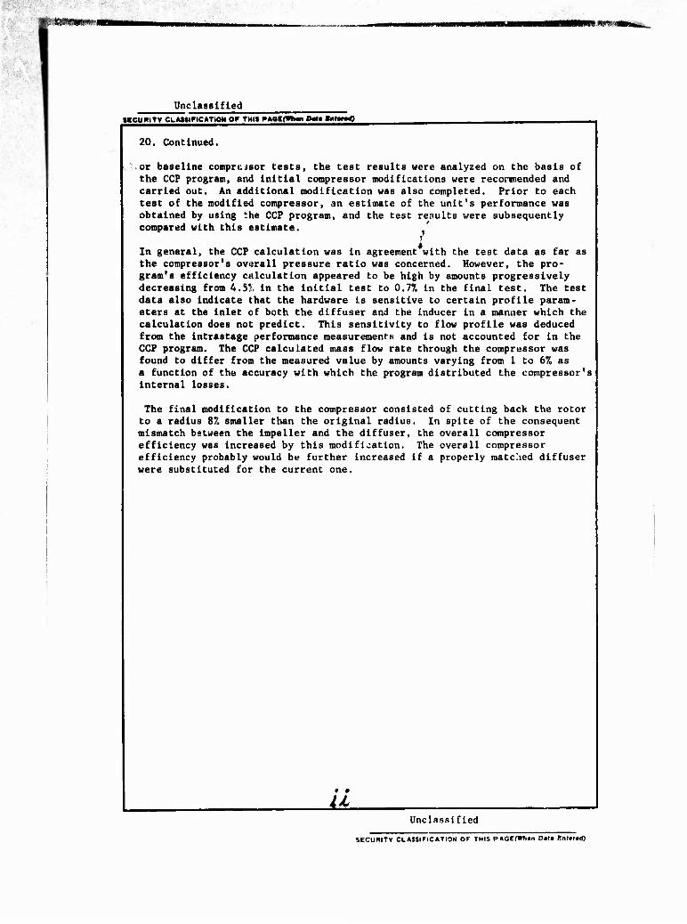
20. Continued.
or baseline comprcisor tests, the test results were analyzed on the basis of the CCP program, and initial compressor modifications were recormended and carried out. An additional modification was also completed. Prior to each test of the modified compressor, an estimate of the unit's performance was obtained by using the CCP program, and the test results were subsequently compared with this estimate.
In general, the CCP calculation was in agreement with the test data as far as the compressor's overall pressure ratio was concerned. However, the pro- gram's efficiency calculation appeared to be high by amounts progressively decreasing from 4.5?, in the initial test to 0.77. in the final test. The test data also indicate that the hardware is sensitive to certain profile param- eters at the inlet of both the diffuser and the Inducer in a manner which the calculation does not predict. This sensitivity to flow profile was deduced from the intrastage performance measurement-s and is not accounted for In the CCP program. The CCP calculated mass flow rate through the compressor was found to differ from the measured value by amounts varying from 1 to 6% as a function of the accuracy with which the program distributed the compressor's internal losses.
The final modification to the compressor consisted of cutting back the rotor to a radius 8% smaller than the original radius. In spite of the consequent mismatch between the impeller and the diffuser, the overall compressor efficiency was Increased by this modification. The overall compressor efficiency probably would be further increased if a properly matched diffuser were substituted for the current one.
M. Unclassified
SECURITY CLASSIFICATION OF THIS PAGEfHTiwi Dmlm Bnffd)

«witlicflnj^Q
MMmmci mTIHCAtlO«
EUSTIS DIRECTORATE POSITION STATEMENT
The conclusions derived from work performed during this centrifugal com- pressor design criteria program underscore a primary, long-standing problem: neither the compressor design nor the prediction of a "paper" compressor's performance can be accurately completed without benefit of detailed definition of the internal aerodynamics of the machine either by rigorous analytical treatment of the geometry or by acquisition of test data. While it nay be possible to complete designs or performance predictions using advanced internal-aerodynamics computer analyses, the most successful attempts at the effort rely on test data either from the hardware under investigation or from another compressor closely related to it.
This report has been reviewed by technical personnel from this Directorate, and the conclusions and recommendations contained herein are concurred in by this Directorate. The project engineer for this contract was Mr. Robert A. Langworthy, Technology Applications Division.
DISCLAIMERS
lYm flndingi in thh rtport ara not to ba conttruad at an official Dapartmant 01 tha Army potition unlan to dadgnatad by othar authoritad documantt.
Whan Gevammant drawing*, «pacification«, or othar data art utad for any purpow othar than in connaction ««Mi a dafinltaly ralatad Qovarnmant procuramant oparation, tha Unitad Stata« Govarnmant tharaby incur« no ratpenaibility nor any obligation whanoavar; and tha fact that tha Qovarnmant may hava formulatad. furnithtd, or in any ««ay «upplitd tha «aid drawing«, «pacification«, or othar data it not to ba ragardad by implication or otharwita at in any mannar lictnting tha holdar or any othar parson or corporation, or convaying any right» or parmiation, to manufacture, uia, or «all any patantad invantion that may in any way ba ralatad tharato.
Treda nanm citad in thit report do not conttituta an official andorwmant or approval of tha UM of tuch eommardal hardware or «oftwara.
DISPOSITION IN8TWUCTION8
Otttroy this report whan no longar naadad. Do not return it to tha originator.
• • •
■ m
PREFACE
The program reported herein was conducted by the Detroit Diesel Allison Division (UDA) of General Motors Corporation for the U.S. Army Air Mobility Research and Development Lab- oratory, Eustls Directorate, under the terms of Contract DAAJ02-73-C-0089, DA Project 1G262207AH89.
The program was directed at DDA by Dr. S. Baghdadi; Dr. W. F. Osborn, the principal ana- lyst, developed the centrifugal compressor performance calculation; and Mr, 13. A. Hopkins was responsible for the design of the RC-2 Compressor. The compressor tests were per- formed under the direction of Mr. W. C. Gitzlaff of the DDA Test Department. Mr. R. M. Kaufman was responsible for the test stand computer programming.
The authors gratefully acknowledge the program guidance provided by Mr. R, A. Langworthy of the Eustis Directorate. USAAMRDL.
I \
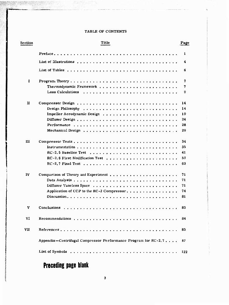
TABLE OF CONTENTS
Section Title Page
Preface 1
List of Illustrations 4
List of Tables 6
I Progran» Theory 7
Thermodynamic Framework . 7 Loss Calculations 9
II Compressor Design 14
Design Philosophy 14 Impeller Aerodynamic Design 19 Diffuser Design 24
Performance 28
Mechanical Design 29
III Compressor Tests 34
Instrumentation 35
RC-2.5 Baseline Test 41
RC-2.6 First Modification Test 57
RC-2.7 Final Test 63
IV Comparison of Theory and Experiment 71 Data Analysis 71 Diffuser Vaneless Space 71
Application of CCP to the RC-2 Compressor 74
Discussion 81
V Conclusions 83
VI Recommendations 84
VII References 85
Appendix—Centrifugal Compressor Performance Program for RC-2.7 .... 87
List of Symbols 122
Preceding page blank

S» ;.■.»»«».,,
LIST OF ILLUSTRATIONS
Figure Title Page
1 2
3
4
5 6
7
8
9
10
U 12
13
14 15
16
17
18 19
20 21
22
23 24
25
26
27
28
29
30
31 32
33 34
Centrifugal compressor loss mechanisms 3
Mollier diagram for centrifugal compressor 8 CCP calculation flow chart 11
Effect of specific spoed on efficiency 15
Effect of vane number change on impeller loading 17
Effect of impeller back-turn angle on diffuser inlet Mach No.
potential flow calculation 18 Effect of back-turn angle on tip speed 18
Computed efficiency—velocity trade-off 20
Impeller vane surface velocities at design point—RC-2 shroud 22
Impeller vane surface velocities at design point—RC-2 hub 22
Angle distribution at impeller inlet 23
Impeller vane angle schedule 24
Vaneless diffuser 25 Vaneless diffuser geometry for fixed throat 26
Pipe diffuser throat blockage factor 26 Plane wail diffuser porformance 27
Compressor rig layout 31
RC-2 Impeller radial stress 33 RC-2 impeller tangential stress 33 RC-2. 7 configuration 34
Throat pressure taps 36 Diffuser exit plane instrumentation ■ . 37
CollectOi outlet instrumentation 38
Removable throat total pressure probe 39
RC-2 impeller (RC-2. 5 and RC-2. 6 configuration) 41
RC-2 diffuser 41
RC-2. 5 performance—25 deg IGV setting 42
RC-2. 5 performance—25 deg IGV setting 43
RC-2. 5 performance—25 deg IGV setting 43
RC-2.5 performance-33 deg IGV setting 44
RC-2. 5 performance—33 deg IGV setting 44
RC-2.5 performance—33 deg IGV setting 45 RC-T;. 5 performance—17 deg IGV setting 46
RC-2. 5 performance —17 deg IGV setting 46

Figure
35
36
37
38
39
40
41
42
43
44
45
46
47
48
49
50
51
52
53
54
55
56
57
58
59
/ LIST OF ILLUSTRATIONS (cc^t)
Title / Page
/ RC -2.5 performance —17 deg IOV setti/ig ' 47
Total pressure distribution at in;pelle!j discharge, inlet guide vane
setting 25 deg / 48
Total pressure distribution at impelder discharge, inlet guide vane
setting 33 deg /. 48
Total temperature distribution at'impeller discharge, inlet guide vane
setting 25 deg 49
Total temperature distribution at impeller discharge, inlet guide vane
setting 33 deg 49
Typical flow angle distribution at Impeller discharge (90 % corrected
speed) 49
Distribution of Mach number and flow angle in vaneless diffuser 56
RC -2.6 performance 58
RC -2.6 performance 58
RC -2.6 performance 59
Impeller outlet total pressure distribution 60
Flow angle at impeller discharge 60
Modified impeller—RC-2.7 configuration 64
RC-2.7 performance 65
RC-2.7 performance 65
RC-2.7 performance 66
Impeller outlet total pressure profile 68
Impeller outlet flow angle profile 68
Diffuser exit peak total pressure ratio—"Break Point" 72
Leading-edge static pressure tap location 74
Variation of slip factor with exducer blade angle 76
Predicted and measured performance — RC-2.6 77
Predicted and measured performance—RC-2.6 77
Measured and matcued performance — RC-2.7 79
Measured and ma ,ned performance—RC-2.7 79

LIST OF TABLES
Table Title Page
Rotor inlet vector quantities 20
Impeller internal exit values 21
Diffuser design parameters 28
Design performance 29
Traverse data reduction program nomenclature for Tables 6, 7, and 8 . . . 50
Yaw'pressure data reduction—RC-2. 5 51
Yaw/pressure data reduction—RC-2. 6 61
Yaw/pressure data reduction—RC-2. 7 69
Comparison of predicted and measured values—RC-2. 5 75
IP Comparison of predicted and measured values —RC-2. 6 . •. 78
i
n\
in A-l
.4
i
Comparison of predicted and measured values—RC-2. 7 80
Intrastage efficiencies of various RC-2 configurations 81
CCP program RC-2. 7 output data 91

3;.j:-;,;:.5^i
I. PROGRAM THEORY
THERMODYNAMIC FRAMEWORK
The Detroit Diesel Allison (DDA) CCP calculation computes compressor pressure ratio and efficiency for each speed line as a function of the mass flow rate.
The relationship between rotor pressure ratio and »^otor Internal efficiency is
r nriuj iy/(r-1)
where i)f j is the rotor internal efficiency defined by
Aqth - Aqri
where Aqri represents rotor internal losses which degrade the rotor pressure, such as aero- dynamic friction losses along the flow surface, losses caused by the growth of the boundary layers in the rotor, blade wake mixing, shock wave losses, and secondary flow losses; AQth is the theoretical head
ce C$V
Qth =- U2 U f 2
= (SF - PF) for a radial exducer. (Note that all the q values are nondimensional- ized by dividing by Ug/Jg.)
The adiabatic (overall) rotor efficiency must account for aerodynamic losses external to the rotor, such as frictional losses* on the rotor back plate, losses caused by the recirculation of low energy fluid in and out of the rotor, and losses associated with the clearance between the rotor and the stationary shroud.
Thus, the compressor's adiabatic efficiency is defined as
n . Aqth " <A{h-i + ^qdiffuser + AqiGV)
ad Aqth + -^external
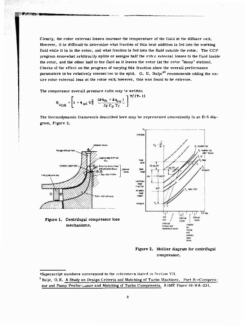
The sum in parentheses in the numerator may be termed the total internal flow losses. This eouation expresses the fact that the internal flow losses decrease the useful output of the com- pressor, while external losses increase the v ork input required to run the compressor. Figure 1 shows the various losses according to their origins.
♦Mechanical losses (such as those caused by bearing and seal frict'on) cannot be accounted for in an aerodynamic calculation.
f&wmtr-
Clearly, the rotor external losses increase the temperature of the fluid at the diffuser exit.
However, it is difficult to determine what fraction of this heat addition is fed into the working
fluid while it is in the rotor, and what fraction is fed into the fluid outside the rotor. The CCP program somewhat arbitrarily splits or assigns half the rotcr external losses to the fluid inside
the rotor, and the other half to the fluid as it leaves the rotor (at the ro+or "dump" station).
Checks of the effect on the program of varying this fraction show the overall performance parameters to be relatively insensitive to the split. O. E. Balje* recommends adding the en-
lire rotor external loss at the rotor exit; however, this was found to be extreme.
The compressor overall pressure ratio may '« written
r -ir/cy-i) - -fi^adui(Aqth :^L
I ad JgCpTr J COA
The thermodynamic framework described here may be represented conveniently in an H-S dia-
gram. Figure 2.
Puiige diftustr loss
Coll«ctor losses
a/
I nlet guide vine loss
/ P( impiriler tip / ifter "dump"
Leading edgelothroit loss
Rolor lip recircu'Mion ^ and clearance losses I Eiternil ® | losses
Rear disk friction
Rotor internal losses
Figure 1. Centrifugal compressor loss mechanisms.
Figure 2. Molller diagram for centrifugal compressor.
♦Superscript numbers correspond to the references listed in Section VII. 1 Balje, O.E. A Study on Design Criteria and Matching of Turbo Machines, Part B—Compres- sor and Pump Perfortuance and Matching of Turbo Components. ASME Paper GO-VVA-231.

• ■ . •
mmmmmmmmmmKr^c-rr*
LOSS CALCULATIONS
The CCP progi-am calculates both Internal and external losses by means of equations derived
theoretically from data correlations and u-om the literature.
Inlet Guide Vane Losses
The inlet guide van >ss?s are computed as a function of the blade turning and the ex" Mach
number. Typically, ais loss amounts to I. 5% of the inlet total pressure at the design point
for RC-2.
Rotor Internal Losses
The calculation of the rotor internal losses is the heart of the CCP program. The calculation
was developed for radial rotore anu subsequently modified to take into account back-curved
rotors. The radial rotor theory is based on a unique relationship between the rotor pressure
coefficient and the tip speed and inlet swirl. The following description applies to radial rotors.
The rotor pressure coefficient, + , is defined as
*= (SF - PF) - Aqri (SF, PF, U, a )
* Aqth - L4ri
(1)
where Aqri is the rotor internal loss. The relationship +=+ (U,a ) has been derived fiom
correlation studies for rotors close to the state of the art, which will be referred to as "model
rotors" in this report. This key relatiinship may be derived from the assumption that, for a
given rotor ideal (isentropic) hend, the rotor internal losses are directly related to the rotor
tip speed. Thus, the model rotor intei-nal loss may be obtained from equation (1),
K) model ' ''(U,a 'model SF + PF
This rotor internal loss is modified by a factor Fm, which accounts for various effects which
CHUSO deviation from (^flrl'model as computed here, so that, for real rotors,
AQri = Fm <Aclri) . where model
Fm zflxf2xf3x "■ --fr n
i?lfi

Each of the factors fj is a modifier by which the rotor internal loss is multiplied to account for a particular effect. Some of the factors fj follow:
(a) The inlet axial Mach number
f! » 1 +Cl(M- Mcri) Cl>0, M. >Mcri
Cj = 0, M < Mcri
where the subscript crj Indicates a critical value,
(b) The indue er tip relative Mach number
f2 = 1 + Ca (Mrei - Mcr2) C2 > 0. Mrel > Mcr2
C2 =0. M<Mcr2
(c) Rotor negative incidence at high Mach number
f3 = 1+ C3i
C3 > 0, i < 0, if Mrel > Mcra C3 = 0, i > 0, or if Mrei < Mcr2
(d) Rotor blade surface roughness
f4 = 1+C4( .- .cr)
C4 >0. . > €cr
C4 = 0. « < tcr
where < is the blade surface roughness.
For rotors close to choking in the inducer, a choke flow coefficient factor is also included.
Except for the latter, all the functions are linear.
The rotor outlet axial (or "wall") blockage at design point is input. Typically, the vaJues
range from 0.85 to 0.95. The rotor outlet wake (or tangential blockage) is calculated at de-
sign point as a function of the rotor pressure ratio, the number of blades, the inlet hub/tip
ratio, and one of three flow quality factors. (Refer to the CCP Calculation Flow Chart, Fig-
ure 3.) These flow quality factors may only be used a posteriori in analyzing test data; ob-
viously, in doing an a priori analysis (i. e., before the machine has been tested) of a machine, the quality of the flow (which is a function of the impeller blading design and the diffuser entry
conditions) cannot at present be determined.
10

■, KW
o o J ^
el s 1 1 BJ ^ 1 i/i ° o> c
c
^ s t- 1 c 1 0
* -— £ S c 1 vt 1 3
*
Vl/ ^5 S 21; Sa
i ™ c
2 r
S -
G>r r ^ a> 1
Oto
rR
stim
ate
- *35
oe ä> s: |
I I
ü
CO
ll ec.E ^
IGV
loss
and
ab
solu
te e
xit
Mac
h No
.
Inle
t di
agra
ms
1 nle
t bl
ocka
ge
«*>,
PF
11

ST
Clearly, the designer intends his blading to produce the highest quality flow (i.e., the lowest wake amplitude). The designer typically uses an inviscid or quasi-inviscid flow calculation
to schedule the impeller blading, and his quality criteria are usually based on the blade sur-
face diffusion factors indicated by this program. However, such programs do not accurately
take into account boundary layer migration and other secondary flow effects that are known to
affect the blading velocity gradients. The proximity of the diffuser leading edges to the im- peller and the number of diffuser passages are also known to affect the impeller flow quality,
although these effects are not yet included in the CCP correlations. This aspect of the com-
pressor performance calculation is still an art. In general, when the CCP program is run
a priori, the blading is assumed to produce high-quality flow and thus a low-amplitude tangen-
tial blade wake.
Both the "wall" and "wake" values of the impeller exit blockage are calculated at off-design
operating points by means of modifiers applied to the design point value (or "amplitude").
These modifiers are functions of dimensionless quantities ^/^ j-jp, where
^ = inlet flow coefficient = Va/U2
U2 is the rotor tip speed, and the subscript DP indicates a design point value.
The aerodynamic slip factor is cplculated at design point by a formula which is based on data
correlations. The slip factor relationship depends strongly on the value of the wake blockage
as well as on the number of blades. The off-design value of the slip factor depends on the
flow factor and tip speed in a manner similar to the impeller exit blockages.
Once the slip factor amplitude has been calculated at ihe design point, the program returns to the calculation of the rotor pressure coefficient and blockages as indicated in the flow chart.
Figure 3. Finally, a new rotor pressure coefficient is computed, and then Aqri is calculated
from equation (1).
The correlations and calculations used in CCP were derived originally for impellers with rad-
ial exducer blading. The calculation was subsequently modified to take into consideration
rotors with back-curved exducer blading. This was done primarily by using the pressure co-
efficient-tip speed correlation to transform a given oack-curved rotor into an equivalent rad-
ial machine 0t each calculation point. In addition, the rotor slip factor and blockage relations
contain terms accounting for back-curvature.
Rotor External Losses
The rotor external losses consist of the rear disk frictional loss, the impeller tip recircu- lation loss, and the losses associated with the clearance between the rotor and the shroud.
12
mMMBmmmmmmmmmmmmmmoBBKtMBmammmmmmm ^^•^^ m..Mmmmmmmmimmimimm.imm
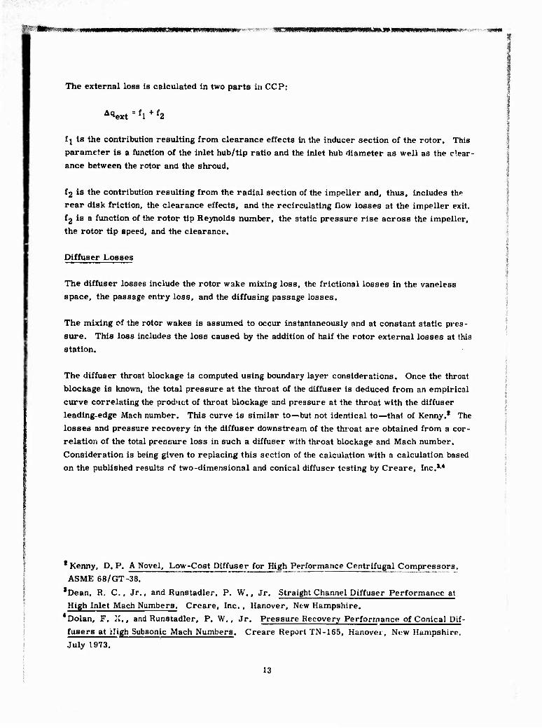
The external loss is calculated in two parts in CCP:
A(iext = fl + f2
f j is the contribution resulting from clearance effects in the inducer section of the rotor. This parameter is a function of the inlet hub/tip ratio and the inlet hub diameter as well as the clear- ance between the rotor and the shroud.
f2 is the contribution resulting from the radial section of the impeller and, thus, includes th" rear disk friction, the clearance effects, and the recirculating flow losses at the impeller exit.
f2 is a function of the rotor tip Reynolds number, the static pressure rise across the impeller, the rotor tip speed, and the clearance.
Diffuser Losses
The diffuser losses include the rotor wake mixing loss, the frictional losses in the vaneless space, the passage entry loss, and the diffusing passage losses.
The mixing cf the rotor wakes is assumed to occur instantaneously and at constant static pres-
sure. This loss includes the loss caused by the addition of half the rotor external losses at this station.
The diffuser throat blockage is computed using boundary layer considerations. Once the throat
blockage is known, the total pressure at the throat of the diffuser is deduced from an empirical
curve correlating the product of throat blockage and pressure at the throat with the diffuser S
leading-edge Mach number. This curve is similar to—but not identical to—that of Kenny.1 The
losses and pressure recovery in the diffuser downstream of the throat are obtained from a cor- relation of the total pressure loss in such a diffuser with throat blockage and Mach number.
Consideration is being given to replacing this section of the calculation with a calculation based on the published results of two-dimensional and conical diffuser testing by Creare, Inc.34
* Kenny, D. P. A Novel, Low-Cost Diffuser for High Performance Centrifugal Compressors. ASME 68/GT-38.
*Dean, R. C., Jr., and Runstadler, P. W., Jr. Straight Channel Diffuser Performance at
High Inlet Mach Numbers. Creare, Inc., Hanover, New Hampshire. 4Dolan, F. Zi., and Runstadler, P. W., Jr. Pressure Recovery Performance of Conical Dif- fusers at High Subsonic Mach Numbers. Creare Report TN-165, Hanover, New Hampshire.
July 1973.
13

II. COMPRESSOR DESIGN
The RC-2 compressor is the second in a series of high-pressure-ratio research compressors designed and built at DDA. The first compressor of this series, RC-1, had a design point pressure ratio of 8:1 and a mass flow of 4.2 Ibm/sec at a specific speed of 70.* The RC-1 de- sign, which used an impeller with a straight radial exducer of high solidity, proved to have an unusually wide range of operation with the peak efficiencies well removed from the surge line.
DESIGN PHILOSOPHY
The purpose of the second design (RC-2) is to provide a unit with a higher efficiency potential than the original design (RC-1). The RC-2 was to k ie as much of the existing RC-1 hardware as was compatible with a reasonable performance improvement increment. Thus, only features believed to be quantitatively important would be included if thepe features materially influenced
costs. On the other hand, any features which could be added at little or no cost could be con- sidered for Inclusion.
In the new design the flow and pressure ratio could be specified to values other than those used for the RC-1. From a research standpoint alone, there is merit in maintaining the same de- sign goals for a series of units to minimize the difficulties of rigorous comparison. Therefore, it was the intent of DDA to carry over the original ilow and pressure ratio goals unless detailed study dictated otherwise.
The major changes to which study was directed were related to:
• Increased specific speed • Decreased friction-producing surface (wetted area) • Scheduled Impeller diffusion • Back-curved impeller blading
A basic change in the design of the RC-2 as compared with the RC-1 was in the area of specific speed (Ng). While specific speed as a performance parameter is not independent of other fac- tors (e.g., Mach number), there are considerable data in the literature which shew that an op- timum exists at a higher value than that of the RC-1. Figure 4 shows examples. Data for Fig- ure 4 are from O.E. Balje and C. Rodgers. While these curves do not agree on the opti- mum specific speed, they do show that a value of 70 as used for the RC-1 is lower than desir- able. The original value of 70 was chosen low in order to achieve a reasonably low inducer Mach number (0.87).
Rodgers, C. A Cyclp Analysis Technique for Small Gas Turbines; Technical Advances in Gas Turbine Design. Paper No. 5, Institution of Mechanical Engineers. April 1969.
"'See Ng under List of S> mbols for definition and i
14

70 80 Specific speed
Figure 4. Effect of specific speed on efficiency.
A specific speed of 90 was believed to be a suitable Increment above the 70 value, and, there-
fore, was used as the design goal. Specific speed can be increased by an increase in airflow
per unit area, an increase in rotative speed, or a reduction in pressure ratio. A change in airflow consistent with retention of inlet ducting would pioduce only a fraction of the desired
specific speed change. In any case, both flow and pressure ratio should be the same as for the
RC-1 for good rarametric comparisons of test data. On the other hand, shaft speed could be
readily changed. The change in specific speed from 70 to 90 produces a comparable change
(+28%) in shaft speed. The existing shaft support system and bearings were considered to be capable of accommodating this speed change. Thus, the specific speed was increased by a
shaft speed change only.
Included in the design philosophy was the intent to decrease the friction-producing wetted area.
In principle, this results in increasing the rate of diffusion, which is also generally referred to as increasing "loading. "
Several interrelated factors are involved in pursuing a loading change. Foremost among these factors is the problem of computing the impeller velocities with sufficient reality so that a
particular diffusion rate can be identified. Then, of course, there is the problem of establish-
ing the criterin for the appropriate diffusion gradients throughout the impeller on both suction
and pressure surfaces. Also pertinent to a change in loading is a review, in general terms, of the relationship of the impeller design procedures to the re; »flow field therein. A thorough
discussion of these generalities has been presented in an ASME publication.
Advanced Centrifugal Compressors. ASME Turbomachinery Committee, Gas Tnrbine Di-
vision, New York. 1971.
15
8
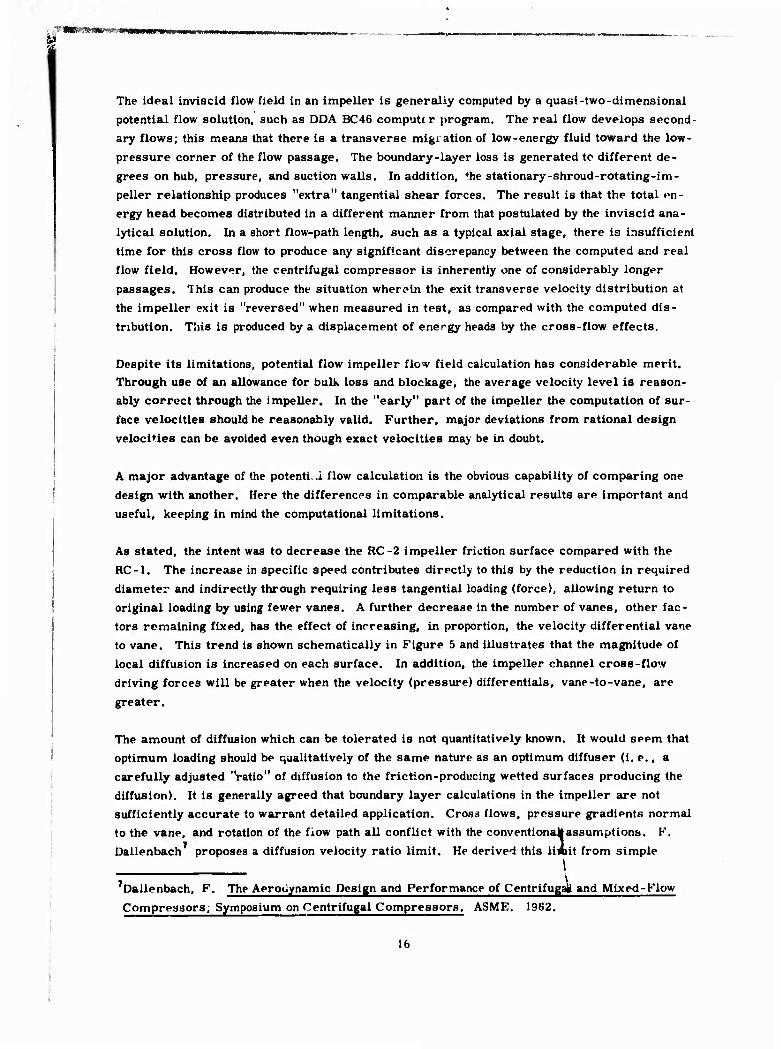
The ideal inviscid flow field in an impeller is generally computed by a quasi-two-dimensional potential flow solution, such as DDA BC46 computtr program. The real flow develops second- ary flows; this means that there is a transverse migration of low-energy fluid toward the low- pressure corner of the flow passage. The boundary-layer loss is generated tc different de- grees on hub, pressure, and suction walls. In addition, ♦he stationary-shroud-rotating-im- peller relationship produces "extra" tangential shear forces. The result is that the total en- ergy head becomes distributed in a different manner from that postulated by the inviscid ana- lytical solution. In a short flow-path length, such as a typical axial stage, there is insufficient time for this cross flow to produce any significant discrepancy between the computed and real flow field. However, the centrifugal compressor is inherently one of considerably longer passages. This can produce the situation wherein the exit transverse velocity distribution at the impeller exit is "reversed" when measured in test, as compared with the computed dis- tribution. This is produced by a displacement of energy heads by the cross-flow effects.
Despite its limitations, potential flow impeller flow field calculation has considerable merit. Through use of an allowance for bulk loss and blockage, the average velocity level is reason- ably correct through the impeller. In the "early" part of the impeller the computation of sur- face velocities should be reasonably valid. Further, major deviations from rational design velocities can be avoided even though exact velocities may be in doubt.
A major advantage of the potenti.i flow calculation is the obvious capability of comparing one design with another. Here the differences in comparable analytical results are important and useful, keeping in mind the computational limitations.
As stated, the intent was to decrease the RC-2 impeller friction surface compared with the RC-1. The increase in specific speed contributes directly to this by the reduction in required diameter and indirectly through requiring less tangential loading (force), allowing return to original loading by using fewer vanes. A further decrease in the number of vanes, other fac- tors remaining fixed, has the effect of increasing, in proportion, the velocity differential vane to vane. This trend is shown schematically in Figure 5 and illustrates that the magnitude of local diffusion is increased on each surface. In addition, the impeller channel cross-flow driving forces will be greater when the velocity (pressure) differentials, vane-to-vane, are
greater.
The amount of diffusion which can be tolerated is not quantitatively known. It would seem that optimum loading should be qualitatively of the same nature as an optimum diffuser (i. e., a carefully adjusted "ratio" of diffusion tc the friction-producing wetted surfaces producing the diffusion). It is generally agreed that boundary layer calculations in the impeller are not sufficiently accurate to warrant detailed application. Cross flows, pressure gradients normal to the vane, and rotation of the flow path all conflict with the conventionakassumptions. F. Dallenbach proposes a diffusion velocity ratio limit. He derived this liAit from simple \
'Dallenbach, F. The Aerodynamic Design and Performance of Centrifugal and Mixed-Flow Compressors; Symposium on Centrifugal Compressors. ASME. 1962.
16

■
■ ■
rmmmftHtitirJiimHtiiivm mmn m .«f-j .»*««w«!i«m*wei^^«i«Wii«WW^ WkH *m
ncreased diffusion with reduced number of vanes
Figure 5. Effect of vane number change on impeller loading.
boundary layer propositions, but it gained credibility by use in a series of designs wherein better performance was obtained than in a series where the proposed limit was exceeded, A
value oi impeller final relative velocity divided by an initial relative velocity of 0, 6 is suggested as a minimum value. The application of this criterion was considered in the RC-2 design.
Qualitative scheduling of the impeller internal diffusion in a manner consistent with simple boundary layer characteristics was considered desirable for the RC-2. Such calculations show
that the accumulated energy loss is less when a given diffusion is obtained by a more rapid
velocity reduction in the early portion than in the latter portion of a diffuser.
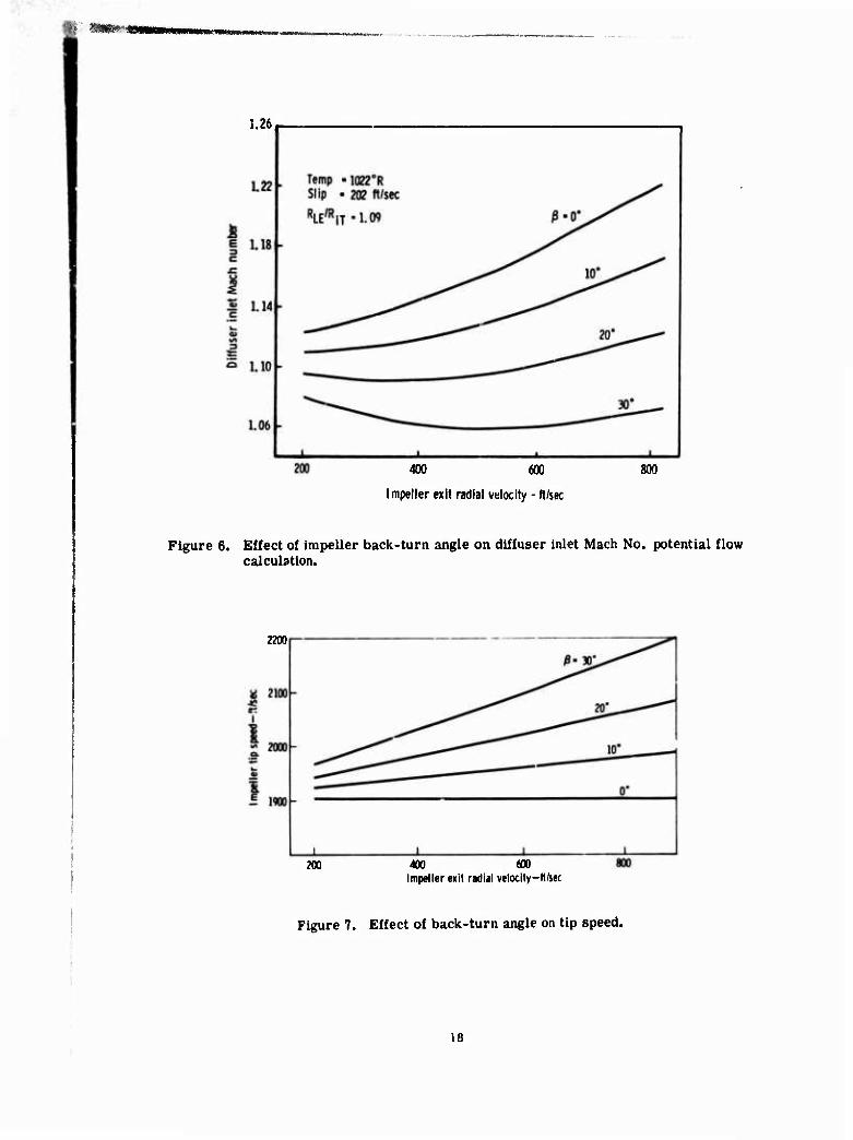
Use • f an impeller that incorporated ^ack-curvature at the outlet was also considered desirable for the RC-2. Such a design reduces the diffuser inlet Mach number for a given vaneless space while adding somewhat to the Impeller diameter. Curves showing such trends are shown in
Figures 6 and 7. One obstacle to the use of a back-curved impeller is the stress produced at the tip as a result of centrifugal force acting on the nonradial section. However, improvements
in the last few years in the stress calculation capability indicate that the stresses in this zone
are not as high as previously assessed and, further, that the use of the titanium material pro- vides superior strength.
17
1.26
400 600
Impeller exit radial velocity - ft/sec
800
Figure 6. Effect of impeller back-turn angle on diffuser inlet Mach No. potential flow calculation.
2200
200 400 600 Impeller exit radial velocit>-ft/sec
Figure 7. Effect of back-turn angle on tip speed.
18

f
IMPELLER AERODYNAMIC DESIGN
The impeller velocity patterns were computed using the DDA BC46 computer program described
by D. M. Davis. The calculation is basically sitraightforward, inviscid solution a la J. D. Stanitz wherein various clerical features (e. g,, data input, solution stations) were most re-
cently influenced by the methods of T. Katsantis «o
The impeller inlet vector diagram quantities sire displayed in Table 1. The inlet guide vanes,
for which the design is reported by B, A. Hopkins, and the inlet ducting were retained from
the RC-1 design. Shaft speed was chosen through use of a specific speed of 90 and the RC-1 values of flow and pressure ratio of 4.2 lb/sec and 8:1, The resulting shaft speed is 56, 000
rpm as compared \vi+h 43, 800 rpm for the RC-1,
The impeller exit radial velocity choice was a matter of considerable deliberation, A high value of exit velocity decreases impeller diffusion but increases the absolute Mach number at the im- peller exit. Logically, the proper value of exit velocity would seem to be that which produces
maximum diffusion consistent with off-design requirements. However, the issue is clouded by the possibility that the impeller exit flow quality may deteriorate, evtn at modest diffusion
levels, to the point where subsequent diffusion recovery is reduced.
The impeller internal flow field is considered to be too complex for boundary layer analysis.
Simple flat plate calculations were nonetheless used as a guide by F, Dallenbach, who sug-
gested that a relative velocity ratio, outlet to inlet, be 0. G or above. This value is supported with several sets of test results showing improvements in performance by the elimination of
excess diffusion.
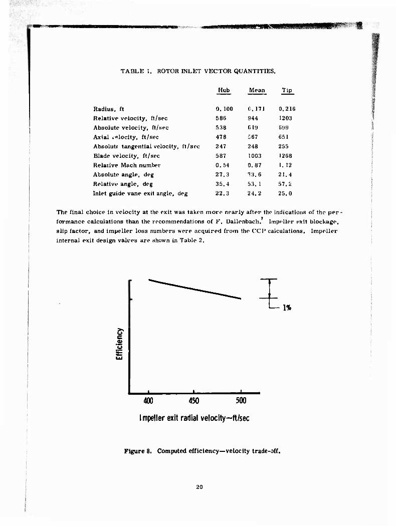
The bulk performance correlation indicates that overall efficiency of the RC-2 compressor
should vary with exit velocity as shown in Figure 8, In this range of interest, efficiency con-
tinues to rise as exit velocity reduces. If a meridional velocity of 400 ft/sec exists at the im-
peller exit, the shroud stream surface relative veloc'ty ratio, outlet to inlet, will be 0, 52,
If computed using maximum suction surface velocity, a value of more nearly 0, 4f> might result. These values are appreciably less than 0.6 minimum as suggested by F. Dallenbach. On the
other hand, to achieve a 0, 6 value, a meridional exit velocity of 600 ft/sec or higher might be required. At this value the CCP calculation would indicate a considerable loss in efficiency.
10
Davis, D, M, Radial Flow Compressor and Turbine Design Program. Mathematics Sciences Report. Detroit Diesel Allison Division, General Motors. August 1971. Staniti, J. D. Some Theoretical Aerodynamic Investigations of Impellers in Radial and Mixed-
Flow Centrifugal Compressors. Trans. ASME, Vol 74, pp 473-407. I!i52.
Katsantis, T. Computer Program for Calculating Velocities and Streamlines on a Blade-to-
Blade Stream Sut face of a Turbomachine. NASA TN D-4525. April 1968. "Hopkins, B. A. Inlet Guide Vane Design for Centrifugal Compressor. Research Note RN 69-79,
Detroit Diesel Allison Division, General Motors. December 1969.
19
■
■ uiuiiijMnmiiR'wiiv"
TABLE 1. ROTOR INLET VECTOR QUANTITIES.
Hub Mean Tip
Radius, ft 0. 100 0. 171 0.216
Relative velocity, ft/sec 586 944 1203
Absolute velocity, ft/sec 538 019 699
Axial .«locity, ft/sec 478 567 651
Absolute tangential velocity , ft/sec 247 248 255
Blade velocity, ft/sec 587 1003 1268
Relative Mach number 0.54 0.87 1. 12
Absolute angle, deg 27.3 T3.6 21.4
Relative angle, deg 35.4 53. 1 57.2
Inlet guide vane exit angle. deg 22.3 24.2 25.0
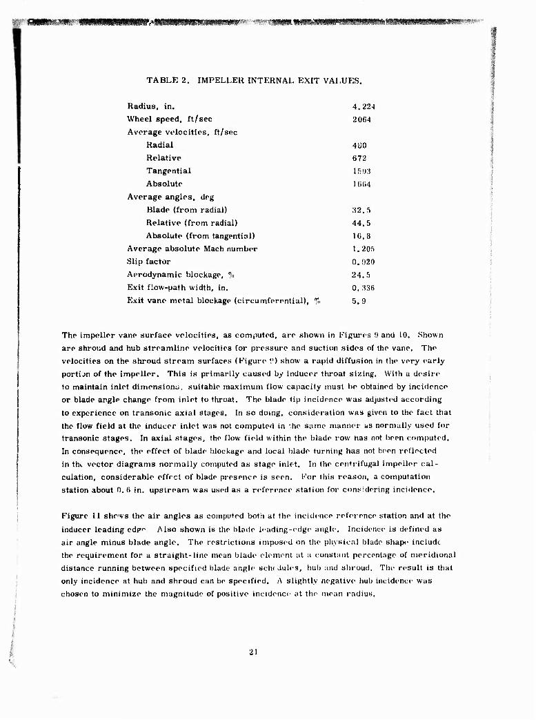
The final choice in velocity at the exit was taken more nearly after the indications of the per-
formance calculations than the recommendations of F. Dallenbach. Impeller exit blockage, slip factor, and impeller loss numbers were acquired from the CCP calculations. Impeller
internal exit design valves are shown in Table 2.
er c 9»
IE
1%
400 450 500
Impeller exit radial velocity—ft/sec
Figure 8. Computed efficiency—velocity trade-off.
20
srnrn-'--'-^ mfßfitwm^m^^wmm^mm^m^^'m^ ■ tmmmm?mmmm^mw'*?m!mmmmm-*^ ■
TABLE 2. IMPELLER INTERNAL EXIT VALUES.
Radius, in. 4.224
Wheel speed, ft/sec 2064
Average velocities, ft/sec
Radial 4U0
Relative 672
Tangential l.r;()oi
Absolute 1 (i(i4
Average angles, dog
Blade (from radial) 32. 5
Relative (from radial) 44.5
Absolute (from tangential) 16.8 Average absolute Mach number 1. 205 Slip factor 0.920
Aerodynamic blockage, % 24.5
Exit flow-path width, in. 0. M6
Exit vane metal blockage (circumferential), % 5. 9
The impeller vane surface velocities, as computed, are shown in Figures 9 and 10. Shown are shroud and hub streamline velocities for pressure and suction sides of the vane. The
velocities on the shroud stream surfaces (Figure 0) show a rapid diffusion in the very early
portijn of the impeller. This is primarily caused by inducer throat sizing. With a desire to maintain inlet dimensions, suitable maximum flow capacity must be obtained by incidence or blade angle change from inlet to throat. The blade tip incidence was adjusted according
to experience on transonic axial stages. In so doing, consideration was given to the fact that
the flow field at the inducer inlet was not computed in *.he same manner as normally used for transonic stages. In axial stages, the flow field within the blade row has not been computed.
In consequence, the effect of blade blockage and local blade turning has not been reflected
in the vector diagrams normally computed as stage inlet. In the centrifugal impeller cal-
culation, considerable effect of blade presence is seen. For this reason, a computation station about 0.6 in. upstream was used as a reference station for considering incidence.
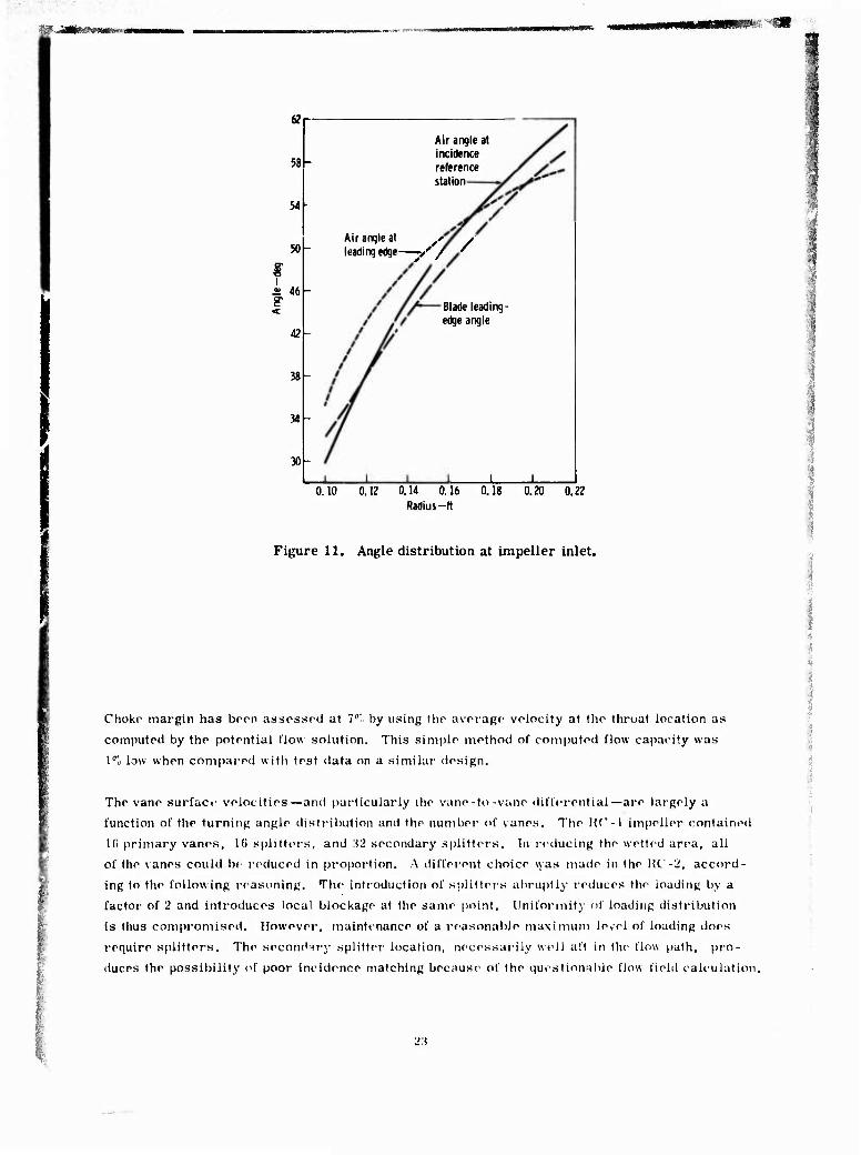
Figure 11 shews the air angles as computed both at the incidence reference station and at the
inducer leading edf'' Also shown is the blade leading-edge angle. Incidence is defined as air angle minus blade angle. The restrictions imposed on the physical blade shape include
the requirement for a straight-line mean blade element at a constant percentage of meridional
distance running between specified blade angle seht Jules, hub and shroud. The result is that only incidence at hub and shroud can be specified. A slightly negative hub incidence was chosen to minimize the magnitude of positive incidence at the mean radius.
21

■
Shroud streamline
Pressure
OL JL.
20 40 60
Meridiondl distance-%
100
Figure 9. Impeller vane surface velocities at design point—RC-2 shroud.
12
10
0
Hub streamline
Suction
JL U. 20 40 60
Meridional distance—%
80 100
Figure 10. Impeller vane surface velocities at design point—RC-2 hub.
W «ÄS**!«««'»» 4
58
54
50-
2> 46 s <
38-
34
30
Air angle at incidence reference station
Air angle at ys y leading edge—v' / S
Blade leading- edge angle
0.10 0.12 0.14 0.16 0.18 0.20 0.22 Radius-ft
Figure 11. Angle distribution at impeller inlet.
Choke margin has boon assossoci at I"1« by using tlio avorago volocity at tho thruat location as
computed by tho potontiai flow solution. This simplo mothod of computod flow capacity was
1% low whon compared with tost data on a similar design.
The vane surfac«' velocities—and particularly iho vano-to-vano differential—are largely a
function of tho turning angle distribution and the number of vanes. Tho Kf'-l impeller contained
16 primary vanes, l(i splitters, and Wl secondary splitters. In reducing the wotted area, all
of the vanes could bo reduced in proportion, A different choice was made in the HC'-2, accord-
ing to the following reasoning. The introduction of splitters abruptly reduces the loading by a
factor of 2 and introduces local blockage at tho same point. Uniformity of loading distribution
is thus compromised. However, maintenance of a reasonable maximum level of loading does
require splitters. The secondary splitter localion, necessarily well aft in the flow path, pro-
duces the possibility of poor incidence matching because of the questionable flow field calculation.
23

For the RC-2 design, the secondary splitters were abandoned, while the number of vanes was
maintained at 16. The loading distribution was adjusted by scheduling the tangential turning.
In the zone where the secondary splitters would normally be required, loading was reduced
by back turning. This load was, in turn, picked up in the knee of the impeller, where solidity
is still high, by overturning. The tangential turning angle schedule is shown -n Figure 12.
The values were basically chosen for the shroud, while hub values result from the need for the
vane itself to be essentially radially oriented for stress reasons, except for the latter portion of the flow path. In the 80-to-90% position of the flow path, the hub angles were held to zero.
The result is that the bad:-curved impeller can be machined to a lesser diameter to make a
radial bladed impeller of approximately the same pressure ratio output. (That is, there is very
little blade loading in the last 8% of the blading.)
DIFFUSER DESIGN
A pipe-type diffuser v.as chosen for the design. The basic changes featured, as compared with
the RC-1, we in ttie choice of diffuser inlet-to-impeller tip radius ratio and in departure from
a constant-width vaneless space.
The effect of radius ratio on vaneless space loss, diffuser inlet Mach number, an^l efficiency
to the diffuser exit (Mach No. = 0. 35) is shown in Figure 13. Diffuser pressure recovery is held at a constant value of 0. 70, and vaneless space loss is from the CCP analysis. Although the vaneless space loss increases with radius ratio, the reduced diffuser inlet ve'ocity allows some-
what greater pressure to be developed at the diffuser exit and, therefore, better compressor
efficiency. However, insufficient data have been available at the higher values of radius ratio
to establish complete confidence in that design regime. In reality, diffuser pressure recovery may vary with radius ratio. The radius ratio for the RC-2 was chosen to be 1,13, comparable
with a reworked RC-1 configuration.
Meridional distance—%
Figure 12. Impeller vane angle schedule.
24

■MMMM mmmmmmmmmmmtimm*mjmi>>M. .<!$*■?
1.10
1.05
M 1.00
0.95
4
3
2
APt/P,
0.84
0.83
0.82-
0 81 -
_L
Exit Mach number
Total pressure loss—%
Compressor efficiency to diffuser exit
_L X 1.08 1.10 1.12 1.14 1.16 1.18
Radius ratio
Figure 13. Vaneiess diffuser.
To reduce the boundary layer buildup on the vaneiess space walls, the width was reduced in
proportion to radius change. Thus, the physical area was maintained constant with radius up to the radius where the pipe ridges are encountered.
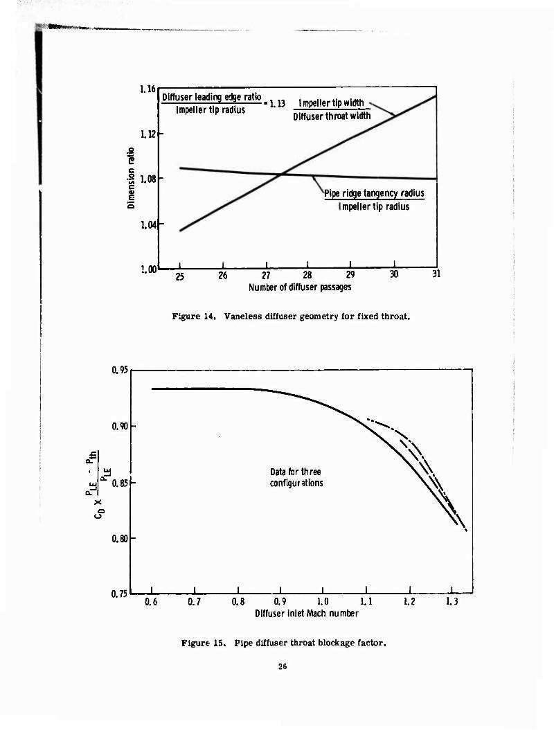
Geometrical relationships among the many variables involved dictate the exact dimensions used.
A constant width was used from the constant area section to the diffuser throat. Thus, the
throat diameter is identical to the final width in the constant area section The throat width is set by choke requirements. Figure 14 shows the trend of the dimensional requirements. A
choice of 27 pipes in the diffuser was made. The variable width section terminates at the pipe centerline tangency radius, and thus-does not enter the pipe ridge zone.
The throat area was chosen to provide a 2% margin to choko. The area is further adjusted to
allow for losses and blockage totaling 8%, according to Figure 15, which was taken from Morris
and Kenny.
if Morris, R. E,, and Kenny, D. P. High-Pressure Ratio Centrifugal Compressors for Sm.\ll
Gas Turbine Engines. Report No. 6, 31st Meeting of the Propulsion and Energetics Panel
of AGARD, Ottawa. Canada. June 196B,
25
1.16
1.12-
.2 1 I 1.08 c H
1.04-
1.00
Diffuser leading edge ratio Impeller tip radius
1.13 Impeller tip width Diffuser throat width
Pipe ridge tangency radius mpeller tip radius
25 26 27 28 29 Number of diffuser passages
30 31
Figure 14. Vaneless diffuser geometry for fixed throat.
0.95
0.90-
£ 0.85-
Q O
0.80-
0.75
"N:^ \N x\
Data for three \^ configurations
\
h
1 1 1 1 1 1 1 1 1 0.6 0.7 0.8 0.9 1.0 1.1
Diffuser inlet Mach number 1.2 1.3
Figure 15. Pipe diffuser throat blockage factor.
26

The diffuser exit Mach number is designed to be 0.35. Diffuser geometry was chosen primarily by reference to high Mach number data from two-dimensional diffusers as discussed by Run-
stadler and Dean* A cross plot of data taken from that report is shown in Figure 16. Per- formance and geometry for two area ratios are shown plotted against blockage. The blockage
at choke of the RC-1 has been computed to be 3.5%, assuming a one-dimensional throat flow. However, this blockage definition is not compatible with the Figure 16 blockage definition. One
to two percent apparently must be added to the 3. 5% in order to use these data from Runstadler
and Dean.
The area ratio was chosen as 2. 15. The diffuser length was based on a length-to-inlet radius
ratio of 11.5.
As on the original design, there was no attempt made to convert the diffuser exit velocity to a higher pressure. It was recognized that there is, in general, a requirement in engine use for
a lower compressor exit Mach number. The performance of a secondary diffuser is conser- v-itively estimated when data are presented to a lower level of Mach number. A value of static
pressure recovery of 0. 30 to a Mach number of 0.15 was assumed for performance calculation.
The diffuser design parameters are presented in Table 3.
0.80
0.75
Y 0.70-
S 3
^ 0.65
0.M-
InletMach number-1.0
14
12 =
I 6 —i
10
0.0? 0.04 0.06 0.08 0.10 0.12 Blockage frxtion-B
Figure 16. Plane wall diffuser performance.
27

.
fjlj^-' -^JH www«*« ;
TABLE 3. DIFFUSER DESIGN PARAMETERS.
Vaneless sp^ce Exit radius (leading edge), in. 4.773 Width at inlet, in. 0.336 Final width, in. 0.3125 Radius at final width (tangency), in. 4. 3484
Total pressure loss, % 2.9
D: fuser Number of pipes 27 Throat diameter, in. 0.3125 Total throat area, in. 2 2.07089 Leadiug-edge wedge angle, deg 8.7 Leading-edge mean angle from tangential, deg 16.4 Diffuser exit/throat area ratio 2. 15 Diffuser exit radius, in. 6.018 Length to inlet radius ratio 11.5 Included cone angle, deg 4. 6 Inlet Mach number 1. 00 Exit Mach number 0. 35 Static pressure recovery coefficient 0. 70
Total pressure drop, % 6.6
PERFORMANCE
The ccmpressor performance was computed by means of the performance prediction calculation
CCP.
In actual compressor rig operation, overall performance was measured at the diffuser exit. Design Mach number was 0.35. A conservative static pressure recovery of 0. 30 was used as an assessment of probable collector and diffusion loss to a Mach number of 0. 15. Perfor- mance numbers were quoted both at diffuser exit and after allowing for the previously mentioned loss for further diffusion.
28

'
I The performance details are given in Table 4; the pressure ratio shown is the originally com-
puted value of 8. 3 at an efficiency of 0. 807 (total-to-total at a Mach number of 0. 15) and a flow
rate of 4.2 Ibm/sec. Later computations with a different slip factor formulation slightly mod-
ified these original design numbers to a pressure ratio of 8. 5 and an efficiency of 0. 805 at a
Mach number of 0.15. These modified design numbers are those quoted in the proposal which
led to the contract work reported herein.
TABLE 4. DESIGN PERFORMANCE.
Flow rate, Ibm/sec Shaft speed, rpm
Specific speed
Pressure ratio and efficiency developed
Impeller exit Diffuser leading edge
Diffuser exit Adjusted to Mach number = 0. 15
Value quoted
Original design value in contract (Table 9)
4.2 4.2
56, 000 56. 000
85 85
R^ T 9.777
1 9.67 0.884 0.8895
9.30 0.864 9.54 0. 869
8.68 0. 829 8. 857 0.825
8.32 0.807 8.5 0. 805
MECHANICAL DESIGN
The mechanical design effort consisted of that required to validate the integrity of the new parts
and to adapt the new design to the existing rig. Thus, certain parts were new as necessary for
dimensional adaptation. The major design effort, however, was the stress and vibration anal- ysis and accommodation of results into the rotating parts.
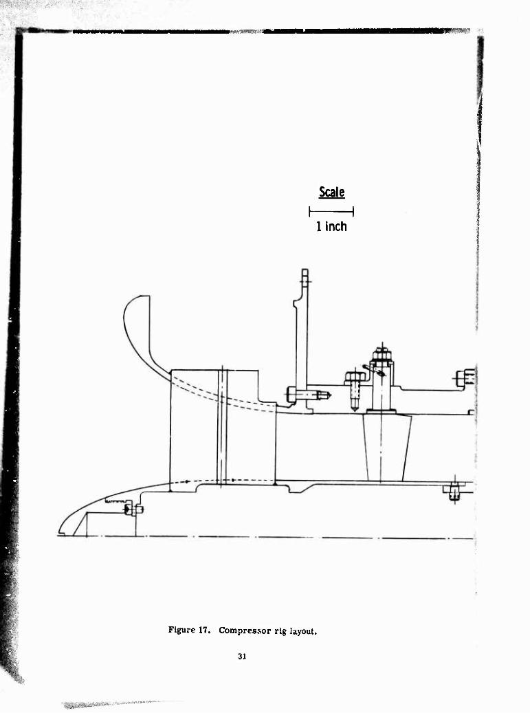
The rig layout may be seen in Figure 17. Air is taken from a 30-in. -diameter inlet plenum by
an inlet bell. Between the inlet Dell and the impeller, inlet guide vanes are cantilever mounted from the outer wall. The inlet guide vanes are adjustable in angle. The inlet bell structure contains four struts supporting an inner body and results in an annular flow path forward of the
impeller. This construction was used to provide a location for installing a shaft-driven strain gage signal transfer device. This provides the structural capability for acquiring stress and
vibration data from the impeller, should it appear necessary.
The inlet ducting as previously discussi-d is unmodified from the RC-1 for the new design, ex-
cept for an adaptor that fills in a gap in the hub flow path.
.
29

«
The impeller is, of course, a new design. The covering shroud also is new. The existing
RC-1 shroud could have been reworked to accommodate the new impeller, but it was retained
to continue testing the RC-1 design. The diffuser also is a new design. The diffuser and shroud are mounted on the main support, which is unchanged except for minor rework.
As on the RC-1, the shaft is integral with the impeller. Detailed rotor dynamic analysis of the system showed that use of the existing bearings and bearing support system would produce excessive radial excursions of the coupling end of the shaft at the new design speed. To avoid this, that end of the shaft required a larger diameter, which, in turn, forced the use of a larger
diameter bearing. Thus, a new bearing housing was required.
is The rotor dynamic analysis is reported by R, Trent. The report states that, while vibratory response is expected to be within acceptable limits, a soft mount for the front bearing should
be considered. Therefore, sufficient design effort was accomplished to ensure that the initial hardware coulii be reworked to provide controlled mount flexibility in the event it should be required.
The impf Her design wis subjected to a vibration analysis as reported by 1-. Burns. Natural
frequencies of the primary vane, splitter vane, and wheel were computed. Certain potential
vibratory modes were identified. However, it is believed that excitation forces for these points
do not exist to sufficient degree to warrant concern.
IS A stress analysis waj made on the titanium impeller, and reported by M. Clute. Str-, ^ües were
computed and are quoted at 7% overspoed. Maximum steady-state stress in the vanes of 54,000
psi occurs in the inducer section of the primary vane. A value of ^2, 000 psi occurs at ar. inter-
mediate meridional position on the primary vane. Splitter vane stresses do not exceed these values. No significant level of stress was computed in the region of the back-curved tip section.
With an assumed 15,000-psi vibratory stress for 10^ cycles, this titanium material can sustain a steady-state load of 76, 000 psi.
The maximum wheel stress, 74,000 psi, occurs at the rear face near the hub. The wheel has no bore. The ultimate tensile strength of the material at 200"h' is 11!), 000 psi.
Trent, R, Dynamic Analysis RC-2 Compi-essor Rotor Case System, Kngineering Department
Report TDR AX, 0220-016, Detroit Diesel Allison Division, General Motors. June llt72.
Burns, L, Vibration Analysis of the RC-2 Impeller. Kngineering Department Report TDR AX, 0201-0:17, Detroit Diesel Allison Division, General Motors. July 1Ü72.
Clute, M, Stress Analysis of the RC-2 Impeller. Kngineering Department Report TDR AX. 0201-036, Detroit Diesel Allison Division, General Motors. July lit72.
30
IW**H(
Scale
I 1 1 inch
Figure 17. Compressor rig layout.
31
: HtCtVim

■
—— .iiwHf*
(^
Scale
1 inch
Figure 17. Compressor rig layout.
31
'fHi'^ti'lil'Miitli't'^'^"""''''"

V
a? ^T-ri|fV

c

■
These wheel and blade stresses were arrived at with an anticipated thermal pattern imposed
as reported by Colborn. Final wheel sti ess values are given in Figures 18 and 19.
Plollmnl
Figure 18. RC-2 impeller radial stress.
Figure 19. RC-2 impeller tangential stress.
it Colborn, J. H. Temperature Distributions in the RC-2 Impeller. Engineering Department Report TOR AX. 0201-035, Detroit Diesel Allison Division, General Motors. May 1972.
Preceding page blank 33

III. COMPRESSOR TESTS
The RC-2 compressor was tested and modified to determine the degree of validity of the per- formance analysis previously described. The first, or baseline, test was run with the com- pressor "as designed," and at two inlet guide vane settings other than Ihc design setting. This
build of the compressor is designated RC-2. 5. RC-2.1 through RC-2.4 wore short rig me-
chanical check runs necessitated by initial rotor whip and vibration difficulties. Instrumenta- tion checks were also obtained during these tests. The tests resulted in the addition of six
rear bearing stiffening struts.
The second test, RC--2, 6, was run with the inlet guide vanes twisted +8 deg at the hub and -8 deg
at the tip, and with the diffuser plated so as to decrease the throat area by 4%. These compres- sor modifications were made as a result of the analysis of the RC-2. j data, which indicated:
• Impeller exit hub-to-Phroud total pressure and angle profiles were weak on the shroud side. • Inducer was starting to choke earlier than the diffuser at design spred.
The third tost, RC-2. 7, was run with the RC-2. 6 hardware, except that the impeller tip diam- eter was reduced by 7. 5%, so the exducer was essentially radial rather ti.an bent back. The
radial space between the impeller tip and the original diffuser was reworked to result in a constant-width vaneless space up to the original vaneless space inlet (see Figure 20). This
impeller modification was suggested by the very rapid blade curvature in the original exducer
design, which apparently resulted in a deviation of the airflow from the blade pressure surface, as evidenced in RC-2. 5 and RC-2. 6 by the higher than predicted work output of the rotor.
Added to make up enlarged vaneless space
Figure 20. RC-2.7 configuration.
34

INSTRUMENTATION
The compressor was instrumented in such a manner that the intrastage losses could be deduced
as accurately as possible. Additional instrumentation was added as the test program progressed and certain areas of concern emerged.
RC-2. 5 Instrumentation
Inlet Station
The compressor's inlet total temperature and pressure were measured upstream of the inlet in a large (36-in.-diameter) plenum. The instrumentation consisted of four static pressure taps
and four total temperature probes.
Inducer Inlet
Three static pressure taps were distributed circumferentially at each of the following locations: ■
• On the shroud, before the inlet guide vanes • On the hub, before the inlet guide vanes • On the shroud, otter the inlet guide vanes
• On the hub, after the inlet guide vanes
In addition, a six-element boundary laynr rake was located on the hub behind the inlet guide vanes.
Impeller Shroud
Two rows of eleven static pressure taps each were distributed along the impeller cover. The two rows wer? separated circumferentially by 125 deg. Three additional taps were distributed
circumferentially at the radius of the last pressure tap of the two rows.
Vaneless Space
The vaneless space instrumentation included:
• Eleven static pressure taps were distributed along the presumed flow p.ith from the im- peller tip to the diffuser throat, on each of the hub and shroud sides of the diffuser.
• Four static pressure taps were distributed circumferentially to span one diffuser passage at a radius 3% outboard of the original impeller tip radius, on each of the hub and shroud
sides of the diffuser.
• Four static pressure taps were distributed circumferentially to span one diffuser passage at a radius 7.7% outboard of the original impeller tip radius (the "tangency" radius of the
pipe diffuser), on each of the hub and shroud sides of the diffuser.
35
i

• Throe total pressure probes were imbedded in the leading edge of the diffuser, one at the apex of the leading edge, and one on either aiCo of the apex. The apex total pressure probe
consistently read a value lower than the maximum diffuser outlet total pressure, thus in-
dicating that this probe was operating at some significant incidence to the flow, so this pressure was discounted.
Diffuser Inlet Throat
Seven static pressure taps were located in the throat of the diffuser. The taps were located
45 deg apart around the circular throat, as shown in Figure 21.
In addition, a static pressure tap was located 0. 10 in. ahead of and 0.10 in. behind the throat on the shroud side of the diffuser.
Diffuser Passage
One static pressure tap was located on each of the hub and shroud sidewalls of the diffuser, one-half the distance between the diffusor's throat and exit plane.
Diffuser Kxit Plane
Three static pressure taps were located at the diffuser outlet: one on the pressure surface, one on the hub iide, and one on the shroud side of the diffuser.
Two 3-clement and two 2-element total pressure rakes wore located at the diffuser exit. The
location of the diffuser exit instrumentation is shown in Figure 22.
Section A • A
Figure 21. Throat pressure taps.
36

IBRüSlBRaiw'x,*»«-.
x Total pressures (or temperatures)
• Static
Note: Each passage contains only two or three probes: Pattern shown is a superposition of all tt.e instrumentation in one passage.
Figure 22. Diffuser exit plane instrumentation.
An identical arrangement with thermocouples instead of pressure rakes was also included at
the diffuser exit. No more than one of the rakes was positioned at any diffuser passage exit. Thus there were rakes positioned behind eight of the twenty-seven diffuser passages.
Collrctcr Outlet
Three 3-element thermocouple rakes were located at the collector outlet in the pattern indi- cated i" figure 23.
Impeller Outlet Traverse Data
Two specially designed total pressure probes wore used to traverse the vaneless space at a radius 7.7% outboard of the impeller tip radius (i.e., at the diffuser "tangency" radius). These
probes were located 180 deg apart, so they were one-half passage apart with respect to a dif- fuser passage. The probes were steel cylinders of 0. 032 in. dia, with a single 0. 007-in. -dia
sensing hole. These probes were yawed at each axial traverse station until the maximum pres-
sure reading was obtained and recorded. The probes were then yawed in one direction until a suitable lower pressure was obtained, and this yaw ;ingle was recorded. The probes were then
rotated in the opposite direction until this last pressure was duplicated, and the angle was re- corded again. The measured flow angle was taken to be the average of the two last recorded angles. However, the angle level was modified in the data reduction program to match con-
tinuity, thus accounting for zero point calibration errors and circunaferential angle variations. In addition, two special thermocouple probes were subsequently substituted for these pressure
37

?3Wfl.;: :.-:." 1!!5P'R«8!S!9W!!I^^
®ä
View A-A
0 - Total temperature probes (thermocouples)
Figure 23. Collector outlet instrumentation.
probes and used to obtain the flow total temperature distribution at the same two locations as the total pressure traverses. These temperature probes consisted of steel cylinders of 0.032 in. outer diameter, with two 0. 015-in. -dia holes 1 ^ deg apart and axially displaced by 0. 032 in. A chei-mocouple was located halfway between these two holes. The thermocouple was
formed by laser-welding two 0. 001 -in. -dia wires (iron and constantan) together. No attempt was made to modify the readings of these probes for recovery factor and wire correction ef-
fects. The traverse data were deleted from the 17-deg inlet guide vane test of RC-2. 5 for
economic reasons.
RC-2.6 Instrumentator!
The RC-2. 6 compressor test included all the instx'umentation described for the RC-2. 5 tost,
except that no temperature traverses were obtained.
RC-2.7 Instrumentation
The RC-2, 7 compressor test included all the instrumentation described for the RC-2. 5 test, except that no temperature traverses were obtained.
33

jj |pH M ^r^wäjt»^,«.,^. ,w;WjtM»«aie^*-«<^wi*w^<»!(»iE,5^*'P^wj^^ ■--■■ ■■ "■■;;■"«!»
Additional instrumentation was provided the compressor for this test in the region of the im-
peller tip, the diffuser throat, and the collector exit as fellows:
• The impeller tip additional instrumentation consisted of five static pressure taps distributed
circumferentially to span one diffuser pa&tiage (i.e., 13.33 deg) at the new impeller outlet radius of 3.91 in.
• The diffuser inlet throat additional instrumentation consisted of:
• Seven static pressure taps 0. 08 in. apart, with the center one at the throat and the others along the pipe centerline on the shroud side
• Four static pressure taps duplicating the one 0. 08 in. upstream of the throat in four other passages
• Three special removable total pressure probes located 0. 05 in. behind the throat
along the pipe centerline. These total pressure probes were removable and could be replaced by "blanks" (see Figure 24).
• The added instrumenta ■ .tt the collector exit consisted of a single total pressure probe
and a single static pi e tap.
Figure 24. Removable throat total pressure probe (left).
39

P e r f o r m a n c e M e a s u r e m e n t s
The c o m p r e s s o r ' s p e r f o r m a n c e was defined in t e r m s of a i r f low r a t e , p r e s s u r e ra t io , speed , and ef f ic iency. The c o m p r e s s o r p e r f o r m a n c e is shown l a t e r .
The airf low ra t e was m e a s u r e d by m e a n s of an ASME s q u a r e - e d g e o r i f i ce plate and was c o r -r ec t ed to s t andard condi t ions . Th i s o r i f i ce m e t e r was ca l ib ra t ed and shown to conform to the ASME s t a n d a r d s " and had an accuracy of ±1/2% of the flow.
The c o m p r e s s o r ' s p r e s s u r e r a t i o was the r a t i o of the a r i t hme t i c ave rage of the m e a s u r e d d i f -f u s e r exit total p r e s s u r e to the a r i t hme t i c ave rage of the m e a s u r e d inlet p r e s s u r e . Th i s m e a -s u r e m e n t has an accuracy of be t t e r than ±1 /4%. The quoted c o m p r e s s o r ef f ic iency was the t rue adiabat ic ef f ic iency ( i . e . , ca lcula ted f r o m the enthalpy tab les r a t h e r than using a con-s tant spec i f ic heat ra t io) . The e f f ic iency calcula ted using a constant y = 1 .4 would be higher than the t rue value by about l"/o at a p r e s s u r e r a t io of 8:1.
("2 " f'lhdeal "adiabatic = (n, - Hl)actual
U 2 ideal ' H 1
" 2 ac tua l " " l
1 he ideal enthalpy r i s e II2 ideal ~ Hi was obtained for the achieved p r e s s u r e r a t i o f r o m the gas tables in Re fe rence 18; the actual enthalpy r i s e H2 actual " H 1 w a s obtained f r o m the m e a s u r e d a r i t hme t i c a v e r a g e t e m p e r a t u r e s at the inlet and the co l lec to r out let . To e n s u r e that no heat was lost between the d i f f u s e r exi t and the co l lec to r exi t , the e n t i r e c o m p r e s s o r was wrapped in f i b e r g l a s s insulat ion. The d i f fu se r exi t t e m p e r a t u r e s w e r e not used to ca l cu -late e f f i c i enc ie s because of the la rge and va r i ed the rmocouple r ecove ry c o r r e c t i o n s r e q u i r e d at the d i f f u s e r exi t , where the t r a n s v e r s e Mach number g rad ien t s a r e very l a r g e . However, the c o r r e c t e d t e m p e r a t u r e m e a s u r e m e n t s taken at the d i f fu se r exit do in fact ag r ee f a i r l y c lose ly with those taken at the co l lec tor exi t .
The accuracy of the eff ic iency m e a s u r e m e n t is approximate ly 11/2% at design speed .
The speed of rota t ion at the c o m p r e s s o r is m e a s u r e d by a digi tal t a chome te r mounted 011 the cont ro l panel in the t e s t s t and . The accu racy of this in s t rumen t i s be t t e r than ±1/10 of 1% of the read ing .
17 !• low .Measurement. ASME Power T e s t Code Commi t t ee , ASME, New York. 1!)50. '* Keenan, J . 11., and Kaye, J . Cias Tab l e s . John Wiley and Sons, Inc . , New York. 1961.
40

KC-2. 5 H.ASE LINE TEST
'I he IU'-2. 5 c o m p r e s s o r was tes ted for p e r f o r m a n c e with 17, 25, and !i:i d i g inlet guide vane se t t ings . Y a w / p r e s s u r e and v a w / t e m p e r a t u r e t r a v e r s e s of the impe l l e r outlet flow w e r e per fo rmed .it the 20 and TA deg ml r t guide vane si t t ings. These t r a v e r s e s could he executed for choked tlow condit ions only, as the c o m p r e s s o r su rged p remature ly with the p robes instal led 1'he impe l l e r and d i f f u s e r a r e shown in F i g u r e s 2T> and 2(i.
F igu re 25. RC-2 impe l l e r (RC-2. 5 and RC-2 . f i configurat ion) .
Total pressure probe
Figure 26. RC-2 diffuser.
41

The test period was 24 September 1973 to 4 October 1973 The reading numbers were 266 to
460, A configuration summary follows:
Configuration Baseline RC-2.5 ("as designed")
Impeller P/N EX-106488
Diffuser P/N EX-106583 27 Pipe IGV assy P/N EX-99257 Collector P/N EX-99270 Cover P/N EX-106582
Impeller tip Cold clearance: 0.035 in.
Compressor Performance Data
Compressor performance maps for each of the three inlet guide vane settings are presented in Figures 27 through 35. The efficiency and pressure ratio plotted in these figures are based on
total pressure measurements at the diffuser exit and total temperature measurements at the
collector exit.
u c
$ 5
r ■
I'M, 000 rp
I \ Inlefpler
1 I urn to diffuser e«il
i .
r 100»N/V m, 27 Pipi diffuser, ICV-
itrr- .r Design sei
y, 16 beam Inq l?5de?
toryMades > A
y /
X >^^
'
y
^
i
b f^ i r
y ̂ 1 i ( Symbols 1 N/V? j
\
I —
a to O 70 1 & » X 85 1 t ^7 O 100 1
1.2 1.6 2.0 2.4 2.8 5.2 3.6 Corrected ilrflow - W»v?/« - lb/sec
4.0 4.4 4.8
figure 27. RC-2.5 performance—25 deg IGV setting.
42

mmr^^^ mmm^^iM^
0.» —
at
I
a?
I |a6
i as
1 ' ; InMdtnumtodMuMrrH 1 1 1 1 UOtN/'« -sa 000 rpn, 27 li*) dllfuser, 16 Primtry. 16 Secondtry Uades
ICV* >tsl9n stHIng <2$dql
1 1
*" 1 «^ m t ^
b
1 j «
+ A f
^ A Symbols Wtf t □ (0 0 JO
r
V 90 O 100
L2 1.6 2.0 2.4 2.8 3.2 1.6 Corracbdiirflow -WiV;/l - ID'MC
4.0 4.4 4.1
Figure 28. RC-2.5 performance—25 deg IGV setting.
0.14 InM pltnum to dlflustrtiK | | j
im,HfVf-H,mrvn. 27 Pipt dlHuser, 16 Prinnry, 16 SKondiry Uadts IGV • Dtslgn sdtlng I TSdigl
an
ai»
.07
| .«1
| a«
3 | £ 0.64 5
0.60
as6
0.S2
a4i
Prmsurt r»tlo-Rr
Figure 29. RC-2.5 performance—25 deg IGV setting.
43

s
1 1 1 1 1 r I i I nie» plenum to diHuser eilt
100 N/WF« 54,000 rpm,Z8 Pipe (tilfuser 16 Prinury, 16 Secondiry I IGV-Reset from design *t (Mdeg)
1.2 1.6 2.0 2.4 2.8 3.2 3.6 i.O 4.4
Corrected airllow - Wa VSVS -lb/sec
Figure 30. RC-2.5 performance—33 deg IGV setting.
.s a 5
0.9
08
0.7
0.6
0.5
Inlet plenum to diHuser exit 100 N/v5-56,000 rpm, 27 Pipe diffuser. 16 Primary, 16 Setondary blades
IGV • Reset from design »8 (33 deyl
Symbols «g/ \ß
D o A rx
I o
^n
60 70 30 85 W
100
0.4
-t
- lij r.
Q
-i_ 1.2 1.6 2.0 2.4 2.8 3.2
Corrected airflow - Wa V9V« - lb /sec
-4 1
6
4.0 4,4
Figure 31. RC-2.5 performance—33 deg IGV setting.
44

smmmmmm^t
0.84
Pressure ratio-Rr
Figure 32. RC-2. 5 performance—33 deg IGV setting.
45

|IWWI|M<MM.|UW"<.| iM6if«lirw»i»iJW*WI<M:ii«l59»''>- '
.9
IUON/V
Symbols 1 DM ore
X85
oioo
1 1 1 1 1 1 Inlet plenum to diffuser exit
V •M.OOü rprn, 21 Pipe diffuser. 16 Primary. 16 Secondary Hades ICV-Reset from design -8 117 deal
i
*) mV»
,/ i/ T
C
o
^ /
y /i \
— >
__ ._
/
..<6 / n }
/ \
i I
yXmb
\ >
I 1.2 1.6 2.0 2.4 2.8 3.2 3.6 4.0 4.4 4.8
Corrected airflow - Wa V9/8 - lb/sec
Figure 33. RC-2.5 performance—17 deg IGV setting.
0.9
I I 1 1 1 1 1 I nlet plenum to iMHuser e«lt
10l)«N/\/« • 56.000 rpm. 27 Pipe diffub»r. 16 Primary, 16 Secondary blades _ IGV-Resetfrom.iesign -8 (I7degl
1.6 2.0 2.4 2.8 3.2 3.6
Corrected airlloM - Wa V9/8-lb/sec
4.0 4.4 4.8
Figure 34. RC-2.5 performance—17 deg IGV setting.
46

flmw^i-v-.- r^<-t^ iJLU'Wilili'B »s^
4 5 6 Pressure ratio-Rr
Figure 35. RC-2.5 performance—17 deg IÜV setting.
47

Impeller Outlet Flow Distribution Data
Two traversing yaw/pressure probea were installed after the coinpletion of the performanee
tests at 25 and 33 deg inlet guide vane settings. Five traverse points were taken between the
hub and the shroud of the compressor, and both the flow total pressure and angle were obtained.
The traverse data were obtained for a choked flow condition only because the presence of the
probes was found to cause the compressor to surge as soon as the flow decreased from its
choke value. Inasmuch as these probes did affect the compressor' performance, all perfor-
mance data were obtained prior to instaiJation of these probes.
Following these pressure surveys, the two temperature probes were installed in the place of
the pressure probes and the traverse was repeated.
figures 3(1 through 40 show the impeller outlet total pressure distribution, total temperature
disinluiuon. and a typical flow angle distribution for both the 25 and 33 deg IGV settings.
5 105
Op^n symbol Pro!» I
Sclid symbol f fobc ?
SVMBOt U/V»
o 100'
D W
O 8V
<1 7P'
Ope" symbol Probe 1 Soliil symbol Probe?
Stiroud 0 r 0 t O.h 0.8 Hub
Aiddl dinension /iliffusef Axul ^yl(tt^
Stirourt n ? 0 4 0.6 0.8 Hub
Axial rtimer« inn/rti'lusef Axial A »"'h
Figure 36. Total pressure distribution at
impeller discharge, inlet guide
vane setting 25 deg.
Figure 37. Total pressure distribution :it impeller discharge, inlet guide
vane setting 33 deg.
48

-*;»> «um
IGV-33 RC-2,5
RC ?.5 1GV"25
Open syrntwl Probe 1 Solid symbol Probe 2
Symbol N/V»
o 100%
G 85%
■^1 O 70%
0 60%
Open Symbol Probe 1 Solid Symbol Probe 2
Svmbol MVS
0 100%
U 90%
Shrouil 0.? 0.4 0> 0,8 Hub Axial dimension /diffuser Axial width
Siuoiiö 0.? 0.4 0,6 0,8 Hub
Axial dimension /diffuser axial *idtn
Figure 38. Total temperature distribution at impeller discharge, inlet guide vane setting 25 deg.
Figure 39. Total temperature dlstrlbutioiv
at impeller discharge, inlet guide vane setting 33 deg.
0 Inlet guide vane setting ?5
0 Inlet guide vane setting 33
30' 1 10' /^N
V\ ; A? 0 4 0, ft 0 8 V ̂
jv Axial dimension diffuser / 10 A f jxial width / /
f
20 r Shi Hid H ib
Figure 40, Typical flow angle distribution at impeller discharge (90% corrected speed).
4!»
W*mm ■ ^**mmm**mr-.ynmi>*™ ii
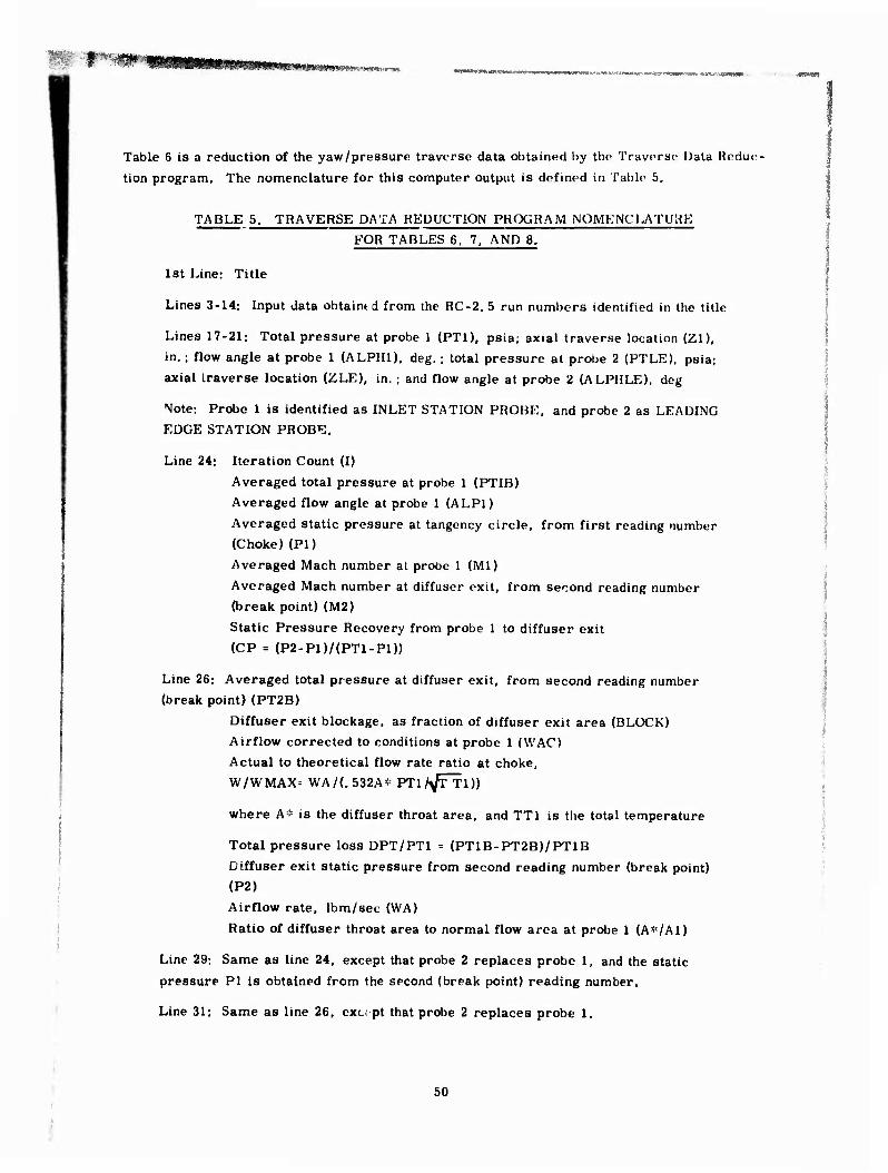
Table 6 is a reduction of the yaw/pressure traverse data obtained by the Traverse Data Reduc-
tion program. The nomenclature for this computer output is defined in Table 5.
TABLE 5. TRAVERSE DATA REDUCTION PROGRAM NOMENClJ\TUHE
FOR TABLES 6. 7. AND 8.
1st Line: Title
Lines 3-14: Input data obtaintd from the RC-2. 5 run numbers identified in the title
Lines 17-21: Total pressure at probe 1 (PT1), psia; axial traverse location (Zl),
in. ; flow angle at probe 1 (ALPH1), deg. ; total pressure at probe 2 (PTLE), psia;
axial traverse location (ZLE), in. ; and flow angle at probe 2 (ALPHLE), deg
Note; Probe 1 is identified as INLET STATION PROBE, and probe 2 as LEADING
EDGE STATION PROBE.
Line 24: Iteration Count (I)
Averaged total pressure at probe 1 (PTIB)
Averaged flow angle at probe 1 (ALP1)
Averaged static pressure at tangency circle, from first reading number
(Choke) (PI)
Averaged Mach number at probe 1 (Ml)
Averaged Mach number at diffuser exit, from second reading number
(break point) (M2)
Static Pressure Recovery from probe 1 to diffuser exit
(CP = (P2-P1)/(PT1-P1))
Line 26; Averaged total pressure at diffuser exit, from second reading number
(break point) (PT2B)
Diffuser exit blockage, as fraction of diffuser exit area (BLOCK)
Airflow corrected to conditions at probe 1 (WAC)
Actual to theoretical flow rate ratio at choke,
W/WMAX= WA/(. 532A* PTl/^TTl))
where A* is the diffuser throat area, and TT1 is the total temperature
Total pressure loss DPT/PT1 = (PT1B-PT2B)/PT1B
Diffuser exit static pressure from second reading number (break point)
(P2)
Airflow rate, Ibm/sec (WA)
Ratio of diffuser throat area to normal flow area at probe 1 (A^/Al)
Line 29; Same as line 24, except that probe 2 replaces probe 1, and the static
pressure PI is obtained from the second (break point) reading number.
Line 31: Same as line 26, exc pt that probe 2 replaces probe 1.
50

s -^i»:^s^^:^ ^
TABLE 6, YAW/PRESSURF DATA RFDUCTION —RC-2. 5.
RC2.6. 25 OEG IGV. 70 PRCNT SPD« RDG 331»AND BREAK PT RDG 279 INPUT DATA FOLLOWS
5 31.7610 29.4510 31.5920 32.6700 45.4000 829.0001 1.98? 0 31.4530 29.4510 31.7150 32.6930
215.4000 55.3000 261.3000 101.4000 0.0000 47,0000 201.0000 409.0000 0.0000 50.0000 247,0000 338,0000 0.0000 52.4000 169.0000 478.0000 0.0000 56.5000 217.0000 414,0000 0.0000 55.0000 136.0000 513.0001 0.0000 59.5000 187.0000 527,0001 0.0000 56.3000 102.0000 539.0001 0.0000 60.2000 153.0000 490,0000 0.0000 51.0000 64.0000 533.0001 0.0000 54.0000 110.0000 493,0000
52.1000 0.1770 52.8000 0.3541 53.2000 0.3541 51.1300 0.3541 49.6300 0.3541 52.3000 0.7082 48.3000 0.7082 48.6000 0.7082 48.8000 0.7082 0.0000 0.0000 0.0000 0.0000
INLET STATION PROBE LEADING EDGE STATION PROBE
PT1 Zl ALPH: PTLE 2LE ALPHLE 47.0000 0.0280 -10.9799 50.0000 0.0278 -26.2799 52.4000 0.0904 1.4400 56.5000 0.0863 -12.5999 55.0000 0.1548 7.7399 59.5000 0.1448 7.7399 56.3000 0.2211 12.4200 60.2000 0.2111 1.0799 51.0000 0.2962 11.3400 54.0000 0.2950 1.6199
INLET STATION DATA ON AVERAGE BASIS
I PT1B ALP1 PI Ml M2 CP 5 54.0470 12.9318 31.3540 0.9174 0.3989 0.6189
PT2B BLOCK WAC M/WMAX DPT/PT1 P2 WA A«/A1 50.6621 0.2413 0.6829 0.9596 0.0626 45.4000 1.9850 1.0361
LEADING EDGE DATA ON AVERAGE BASIS
I PT1B ALP1 PI Ml M2 CP 7 58.8421 11.7908 31.3119 0.9937 0.3989 0.5117
PT2B BLOCK WAC W/WMAX 0PT/PT1 P2 WA A«/A1 50.6621 0.2413 0.6273 0.8816 0.1390 45.4000 1.9850 1.1347
RC 2.5. 25 DEG IGV« 85 PRCNT INPUT DATA
38.6100 43.140 37.8000 43.4000
5 44,9400 44.2000
215.4000 0.0000 0.0000 0.0000 0.0000 0.0000
53.3000 79.8000 78.1000
0.0000 INL
PT1 77.0000 85.5000 91.2000 93.4000 81.5000
55.3000 77.0000 85.5000 91.2000 93.4000 81.5000 0.1770 0.3541 0.7082 0.0000
261.3000 201.0000 169.0000 136.0000 102.0000 64.0000 84.6000 83.1000
0.0000
SPD« CHOKE FOLLOWS 0 47.290Ü
47.0000 101.4000 410,0000 476.0000 515.0001 552.0001 546.0001
0.3541 0.7082
0.0000 ET STATION PROBE
21 0.0280 0.0904 0.1548 0.2211 0.2952
ALPHl •10.7999 1.0799 8.100C 14.7599 13.6799
RDG 334,AND BREAK PT R05 312
72.1000 960.2000 2.9460
0.0000 0.0000 0,0000 0.0000 0.0000
84.7000 76.5000
77.5000 8"'.8000 92.5000 93.0000 78.0000 0.3541 0.7082
247.0000 217.0000 187,0000 151.0000 110.0000 81.3000 74.3000
355.0000 441.0000 476.0000 486.0000 491.0000
0.3541 0.7082
LEADING EDGE STATION PROBE
PTLE 2LE ALPHLE 77,5000 0.0278 -23.2199 87.8000 0.0863 -7.7399 92.5000 0.1448 -1.4400 93.0000 0.2111 0.3600 78.0000 0.2950 1.2599
51

TA ULK 6, (CONT)
INLET STATION DATA ON AVERAGE BASIS
I 5
PTIB 88.6841
ALPl 12.6809
PT2B 80.6411
BLOCK 0.2452
WAC 0.6648
■1
JV. Ml
1.1326 M2
0*4031
W/WMAX 0PT/PT1 P2 0.934, 0,0906 72,1000
LEADING EDGE DATA ON AVERAGE BASIS
CP 0.6601
MA 2.9460
A»/A1 1.0562
I PTIB ALPl PI Ml M2 CP 7 88.5079 12.5859 42.8624 1.0726 0.4031 0.6405
PT2B BLOCK WAC Xf/WMAX DPT/PT1 P2 WA A»/A1 80.6411 0.2452 0.6661 0.9361 0,0888 72.1000 2.9460 1.0641
RC 2,5 25 DEG IGV,90 PRCNT SPDt CHOKE INPUT DATA FOLLOWS
RDG 3H3.AND PREAK CT RDG ?92
48.4<,00 42.0000 46.2500 52.l,0OO 74,400C 1001.6000 3.2780 49.7000 42.2000 46.4000 52.9000
2 I6,0000 55.3000 261.0000 101.4000 0.0000 ^2.0000 201.0000 396.0000 0.0000 et.sooo 247.0000 380.0000 0.0000 103.0000 169.0000 474.0000 0.0000 96.2000 217.COCO 438.000C 0.0000 109.0000 136.0000 521.0001 0.0000 101 .5000 187.0000 472.0000 0.0000 110.0000 102.0000 560.0001 0.0000 10U.O000 153.00C0 493,0000 0.0000 97.8000 64.0000 551.0001 0.0000 85,0000 UO.OOCC 474.COCO
90.9000 0.1770 91.9000 0.3541 90.1000 0.3'54l 88.6000 0.3541 86.5000 0.3541 86.5000 0.7082 79.8000 0.708? 81.3000 0.7062 84.1000 0.7082 0.0000 0.0000 0.0000 0.0000
INLET STATION PROS'-" LEADING EDGE jTATION PROBE
PT1 11 ALPHl DTLE 2LE ALDHLE
92.0000 0.0273 -13,3199 86.5000 0.0273 -18.7200 103.0000 0.0896 0.7200 96.2000 0.0858 -8.2300 109.0000 C.1S40 o.ieoo 101.50^0 0.1443 -2.1599 110.0000 0.2203 16.2000 100.8000 0.2106 1.6199 97.8000 0.2944 14.5",99 85.0000 0.2944 -1.79<59
INLET STATION DATA ON AVERAGE BASIS
PT2B 86.0063
PTIB 106.2073
BLOCK 0.2746
ALPl 12,0551
PI 47,0055
Ml 1.1450
WAC W/WMAX DPT/PT1 0.6308 0.8866 0,1902
M2 0,4598
P2 74,<«000
CP 0,4627
WA 3.2760
A»/Al 1.1102
LEADING EDGE DATA ON AVERAGE BASIS
I 6
PTIB 96.1033
MLPl 13,1589
PI 47,5557
Ml 1,0550
M2 0.4598
CP 0.5529
PT2B 86.0063
BLOCK 0.2746
WAC 0,6972
W/WMAX 0,9799
DPT/PT1 0,1050
P2 74.4000
WA 3.2780
A»/A1 1.0185
32

TABLE 6. (CONT)
RC295 25 DEG IGVtlOO PRCNT SPDt CHOKE ROG 339.AND BREAK PT INPUT DATA FOLLOWS
90.2000 54.6000 55.3000 101.0000 1102.850 > 56.8000 59*4000 50
215.0000 55 109.0000 109 109.0000 123
0.0000 132 0.0000 136 0.0000 114
116.4000 0 113.1000 0 110.7000 0
0.0000 0 INLET
ROG 301
1 3.8730 .0000 .3000 .0000 .0000 • 0000 • 0000 • 0000 .1770 • 3541 • 7082 • 0000
54*6000 261.0000 201.0000 169.0000 136.0000 102*0000 64.0000 121.4000 120.3000
0.0000 STATION PROSE
PT1 109.0000 123.0000 132.0000 136.0000 114.0000
11 w.0273 0.0896 0.1540 0.2203 0.2944
ALPMl •11.1599
8^6399 16.7400 17.0999 50999
56.3000 101.4000 406.0000 518.0001 563.0001 565.0001 500.0000
0.3541 0.7082
0.0000
0 0 0 0 0
118 106
.0000
.0000
.0000
.0000
.0000 • 2000 .2000
10*0000 23.0000 31.0000 31.0000 10*0000 0.3541 0.7082
247*0000 217*0000 167*0000 153.0000 110.0000 113.1000 106.0000
323.0000 448.0000 527,0001 563.0001 460.0000
0*3541 0.7082
LEADING EDGE STATION PROBE
PTLE 110.0000 123.0000 131*0000 131*0000 110*0000
ZLE 0*0273 0*0858 0*1443 0*2106 0*2944
ALPHLE -28*9799 -6*4799
7*7399 14*2199 -4*3199
INLET STATION DATA ON AVERAGE BASIS
I PT1B ALP1 PI Ml M2 6 129*8408 12*3485 54.5900 1*1851 0*4240
PT2B BLOCK 114*2947 0*2794
WAC W/WWAX DPT/PT1 P2 0*6398 0.8991 0*1197 101*0000
LEADING EDGE DATA ON AVERAGE BASIS
CP 0*6167
MA 3*6730
A»/A1 1*0842
I PT1B ALP1 PI Ml M2 CP 8 128*3320 12*3969 56.1546 1*1540 0*4240 0*6*13
PT2B BLOCK WAC W/WMAX 0PT/PT1 P2 WA 114*2947 0*2794 0*6473 0*9097 0*1093 101*0000 3*6730
A«/A1 1*0799
***mmmiwiMW*wi***t**ti***m*m*iitmmm**mitMi*0tM<*i***imiwwmrii**tttift*0i***0i0im0im*0m0itm0i*ti**0*
RC2*5i 33 DEG IGV*.70 PRCNT SPD» CHOKE RDG 394.AMD BREAK PT RDG 360
2*0230 5 31*4800 31*5700
215*4000 0*0000 0*0000 0*0000 0.0000 0.0000
51.8500 49.1000 44.4000 0.0000
INL
PT1 49.0000 53*0000 56*0000 96*5000 50*0000
29*49 29.4900 55.3000 49.0000 53.0000 56.0000 56.5000 50.0000 0.1770 0.3541 0.7082 0.0000
PT STAT
Zl 0.0280 o.o«: 04 0*1548 0*2211 0*2952
INPUT DATA FOLLOWS 00 30*6900 32*9900
31*9300 32.6000 44.6000 817.1000
261.3000 201.0000 169.0000 136.0000 102.0000 64.0000 52.8200 51.6000
0.0000 ION PROBE
ALPHl -5.7600 2*3400 9.5399 13*1399 6*6599
101*4000 436*0000 483*0000 523.0001 543.0001 507.0000
0.0000 0.0000 0.0000 0.0000 0.0000
0.3541 53.2000 0.7082 47*8000
0*0000
44*0000 247*0000 52*5000 217*0000 55*0000 187*0000 56.0000 153.0000 51*0000 110*0000 0*3541 5T.9000 0.7082 46*1000
353*0000 477^0000 513^0001 535.0001 518.0001
0.3541 0.7082
LEADING EDGE STATION PROBE
PTLE ZLE ALPHLE 44*0000 0.0276 -23.5799 52*5000 0*0663 -1*2999 55.0000 0.1448 5.2200 56.0000 0.2111 9.1600 51.0000 0.2950 6.1199
53

"■'«ft.'WWMimy.-;» >■*«-"
I PT1B ALP1 PI Ml M2 CP 5 54.0933 13.0580 31.0494 0.9270 0.4263 0.5880
PT2B BLOCK WAC W/WMAX DPT/PT1 P2 WA A»/Al 50.5370 0.2704 0.6904 0.9703 0.0657 44.6000 2*0230 1.0262
LEADING EDGE DATA ON AVERAGE BASIS
I PT18 ALP1 PI Ml M2 CP 8 54.7472 12.8926 31.2827 0.9311 0.4263 0.5675
PT2B BLOCK WAC W/WMAX DPT/PT1 P2 WA A»/A1 50.5370 0.2704 0.6822 0.9587 0.0769 44.6000 2.0230 1.0392
RC 2.5t 33 DEC IGV. 80 PRCNT SPD» CHOKE RDG 398 AND BREAK PT RDG 366 INPUT DATA FOLLOWS
5 38.8000 34.3000 38.3000 41.0000 58.2000 900.0001 2.5700 38.9000 34.5000 38.7000 41.2000
215.4000 55.3000 261.3000 101.4000 0.0000 67.0000 201.0000 459.0000 0.0000 66.0000 247,0000 413.00(J0 0.0000 74.0000 169.0000 486.0000 0.0000 76.0000 217.0000 470.0000 0.0000 77.0000 136.0000 521.0001 0.0000 80.5000 187,0000 509.000' 0.0000 76.8000 102.0000 542.0001 0.0000 80.1000 153.0000 524.00CI 0.0000 57.0000 64.0000 435.0000 0.0000 71.5000 110,0000 523.0001
69.6000 0.1770 70.6000 0.3541 70.6000 0.3541 67,8000 0.3541 65.5000 0.3541 67.8000 0.7082 62.6000 0.7082 59,9000 0.7082 60.1000 0.7082
0.0000 0.0000 0.0000 0.0000 INLET STATION PROSE LEADING EDGE STATION PROBE
PT1 21 ALPH1 PTLE ZLE ALPHLE 67.0000 0.0280 -1.9799 66.0000 0.0278 -12.7799 74.0000 0.0904 2.8800 76.0000 0.0863 -2.5199 77.0000 0.1548 9.1800 80.5000 0,1446 4.5000 76.8000 0.2211 12.9599 80.0000 0,2111 7.1999 57.0000 0.2952 -6.2999 71.5000 0.2950 7.0199
INLET STATION DATA ON AVERAGE BASIS
I PT1B ALP1 PI Ml M2 CP 5 73.0926 12.8229 38.0190 1.0132 0.4338 0.5753
PT2B BLOCK MAC W/WMAX 0PT/PT1 P2 WA A»/A1 66.2359 0.2679 0.6812 0.9574 0.0938 58.200C 2.5700 1.0447
LEADING EDGE DATA ON AVERAGE BASIS
I PT1B ALP1 PI Ml M2 CP 8 77.1701 12.1620 38.2377 1.0539 0.4338 0.5127
PT2B BLOCK WAC W/WMAX BPT/PT1 P2 WA A«/Al 66.2359 0.2679 0.6452 0.9068 0.1416 58.2000 2.5700 1.1006
RC2.5 33 DEO IGV.. 90 PERCENT SPD. CHOKE. RDG 401 INPUT DATA FOLLOWS
5 47.0650 40.0800 43.7770 50.384C 50.0000 994.0001 3.169C 46.5760 40.0800 44.7160 51.1070
215.4000 55.3000 261.3000 101.4000 0.0000 87.0000 247.0000 39S.0000 0.0000 84.0000 201.0000 404.0000 0.0000 94.0000 217.0000 460.0000 0.0000 96.0000 169.0000 464.0000 0.0000 LOO.0000 187.0000 503.0000 0.0000 103.0000 136.0000 510.0000
54
TABLE 6. (CONT)
INLET STATION DATA ON AVERAGE BASIS

^mfmm-'Jm^-^f: mrnmmmmmtwm^ *■■. !■?*«-•'
TABLE 6. (CONT)
0*0000 98*0000 193*0000 531*0001 0*0000 91.0000 110*0000 472*0000
0*0000 104*0000 102*0000 529*0001 0*0000 91*0000 64*0000 510*0000
64*5000 0.1770 8b.7860 0*3541 63*2830 0*3941 62*1660 0*3514 80*1100 0.3541 76.0660 0*7082 73*5290 0*7082 69*2790 0*7082 76*2050 0*7082 0*0000 0*0000 0.0000 0*0000
INLET STATION PROBE LEADING EDGE STATION PROBE
f»Tl 21 ALPH1 PTLE 2LE ALPHLE 87*0000 -0.0616 -13.5000 84*0000 0*1175 -14*3999 94*0000 -0.0031 -1.799. 96*0000 0.1799 -3*5999
100*0000 0.0553 5.9399 103*0000 0*2443 4.6800 98*0000 0.1216 10.9799 104*0000 0*3106 6.1000 91*0000 0.2055 0.3600 91*0000 0*3647 4*6800
INLET STATION DATA ON AVERAGE BASIS
I PT1B ALP1 Pl Ml M2 CP 4 95.5370 12.8065 44*8928 1*0973 0*8179 0*1006
PT2B BLOCK MAC W/MMAX 0PT/PT1 P2 WA A«/Al 77*5662 0.4394 0.6794 0*9492 0.1681 90*0000 3*1690 1*0461
LEADING EDGE DATA ON AVERAGE BASIS
I PT1S ALP1 Pl Ml M2 CP 7 101.4961 12.1301 45*3663 1*1372 0*8179 0*0125
PT2B BLOCK MAC W/WMAX 0PT/PT1 P2 WA A«/Al 77*5662 0.4394 0.6357 0*6935 0.2397 90*0000 3*1690 1*1034
RC2*5 33 DEG ICV.100 PRCT SPD* RDG 404-CH0KE« AND 389 -BREAK PT INPUT DATA FOLLOWS
5 53*1000 46.6400 49*4900 54*0000 96.6000 1097.2001 3*6490 0*0000 0.0000 0.0000 0*0000
215*0000 55.3000 261.0000 101*4000 0*0000 103.0000 201.0000 369*0000 0.0000 0*0000 0*0000 0.0000 0*0000 118.0000 169.0000 457*0000 0.0000 0*0000 0*0000 0.0000 0*0000 128.0000 136.0000 555.0001 0.0000 0.0000 0*0000 0.0000 0*0000 130.0000 102.0000 534*0001 0.0000 0.0000 0*0000 0.0000 0*0000 108.0000 64.0000 511*0000 0*0000 0*0000 0*0000 0.0000
111*2000 0.1770 115.4000 0*3541 111*0000 0*3941 107*7000 0*3541 108*5000 0.3541 114.8000 0*7082 101*4000 0*7082 101*1000 0*7082 105*4000 0.7082
0*0000 0.0000 0.0000 0*0000 INLET STATION PROBE LEADING EDGE STATION PROBE
PT1 21 ALPHl PTLE 2LE ALPHLE 103*0000 0.0273 -14.5799 0*0000 0*5089 -87*1199 118.0000 0.0896 -2.3400 0*0000 0*5069 -87*1199 128*0000 0.1540 19.2999 0*0000 0*5089 -87,1199 130*0000 0.2203 11.5200 0*0000 0*5069 -87*1199 108*0000 0.2944 7.3799 0*0000 0*5069 -87*1199
INLET STATION DATA ON AVERAGE BASIS
I PT1B ALP1 Pl Ml M2 CP 5 124.4537 12.2121 50*2532 1*2160 0*4166 0*6246
PT2B BLOCK MAC M/WMAX OPT/PTl P2 WA A»/Al 108.8595 0.2791 0.6272 0*8615 0*1293 96*6000 3*6490 1*0961
55
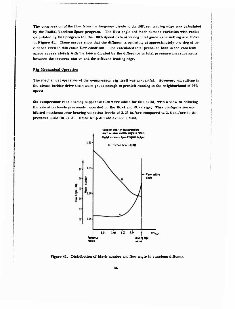
The progression of the flow from the tangency circle to the diffuser leading edge was calculated by the Radial Vaneless Space program. The flow angle and Mach number variation with radius calculated by this program for the 100% speed data at 25 deg inlet guide vane setting are shown in Figure 41. These curves show that the diffuser is operating at approximately one deg of in- cidence even in this choke flow condition. The calculated total pressure loss in the vaneless space agrees closely with the loss indicated by the difference in total pressure measurements between the traverse station and the diffuser leading edge.
Rig Mechanical Operation
The mechanical operation of the compressor rig itself was uneventful. However, vibrations in the steam turbine drive train were great enough to prohibit running in the neighborhood of Qb% speed.
Six compressor rear bearing support struts were added for this build, with a view to reducing the vibration levels previously recorded on the RC-1 and RC-2 rigs. This configuration ex- hibited maximum rear bearing vibration levels of 2.25 in./sec compared to 3.6 in./sec in the previous build (RC-2. 2). Rotor whip did not exceed 6 mils.
Van«)«« dllfu'tr flaw piranitltn Mach numbtr and flow iiql« vt radius
Radial Vaneltss Space Program Output
(or friction factor-0.DM
-—Van« seltlrq angle
itii
1.01 l.tt 1,03 1.04 RfR. Ian Tangency radius
Leading edge radius
Figure 41, Distribution of Mach number and flow angle in vaneless diffuser.
56

RC-2.6 FIRST MODIFICATION TEST
The RC-2. 6 compressor was modified from the original design by t* .sting the inlet guide vanes
+8 deg at the hub and -8 deg at the tip, and plating the diffuser flow path 0. 003 in. The modi- fied compressor was tested for performance, and then yaw/pressure data was obtained in the
manner described in the RC-2. 5 Baseline Test Report at the 25 deg IGV setting.
The test period was 29 and 30 January 1974. The reading numbers were 461 to 552. A con- figuration summary follows:
Configuration Modified RC-2 compressor
ImpeUer P/N EX-106488
Diffuser P/N EX-106583-1 Plated 27 Pipe IGV assy P/N EX-99257-1 Twisted CoUector P/N EX-99270 Cover P/N EX-106582
Impeller tip Cold clearance: 0.035 in.
Compressor Performance Data
The modified compressor performance is shown in Figures 42, 43, and 44, The measuring
stations and methods were identical to those described in the RC-2. 5 Baseline Test Repor'..
The rig was insulated in the same manner as was RC-2.5.
Impeller Outlet Flow Distribution Data
The two total pressure/yaw probes described in the RC-2. 5 Baseline Test subsection were used to obtain traverse data in the manner described previously.
Figures 45 and 46 show, respectively, the impeller outlet total pressure distribution and typical flow angle distributions.
Table 7 is a reduction of the yaw/pressure traverse data obtained by the Traverse Data Reduc- tion program. The nomenclature for this computer output is defined in Table 5.
Rig Mechanical Operation
The mechanical operation of the rig itself was uneventful. However, vibrations in the steain turbine drive train were great enough to prohibit running at 85% speed. Data were obtained at
86% speed since the vibration level there was acceptable.
57
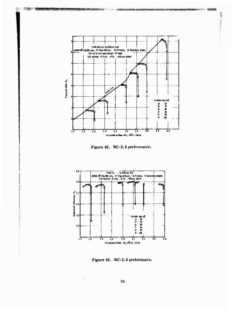
''*^!!ßfä#iti0fW>M!lWMWi^ »w»»«iawswfc*s>m^
f 9 15 e
/ A 1 1 Inlet plenum
\ to diffuser e>lt
1M»N/Vf •SI.OOO rpm, 27 Pl(« diffuser, 16 Prlrwry, 16 Stantory Mades / e ICV set to mid span design I2i degl r
IGVt» Isled »8 hub, -Slip r diffuser Hated
/ W***i. [
A h *—■
o
/~ 1 Y
> ̂ i i
Symbols W/^f □ 60
y - O 70 t. 80 — flÖMW, /ÄOt } 1 X 86
S V « S i 0 100
\
1.2 1.6 2.0 2,4 2.8 J.2 3.6 4.0 4.4 4.8
Corrected »irfloK-Wa V*/8-lb/sec
Figure 42. RC-2.6 performance.
o.«
0.8
0.7
S 8 I a as
0.4
1 Inlet »It lo diffuser «it
10OW/^-S^000:pm. 27 Pipe diffuser, 16
ICV twisted «8 hub. -8 tip ; diffus
Primery, r plated
ir i 16 Second,
1 ryWad«
tf*^ \ ^
<*. \
^ l»^"
1
\ > -
\ —r 4—i r— "1
I S,r
-
-JL
Ms W/t 0 60 O 70 A 80 > 86 V « o loo l
f
C 0.6
1.2 1.6 2.0 2.4 2.8 3.2 3.6
Correctedilrflow -Wj v7/<-lb/sec
4.0 4.4
Figure 43. RC-2.6 performance.
58

wm*mmm®mmmmmmmm&*^ ■''■-«
Pressure ratio—Rr
Figure 44. RC-2.6 performance.
59

RC-2.6
Open symbol Probe 1
Solid symbol: Probe?
Symbol N/yf
0 100»
Figure 45. Impeller outlet total pressure distribution.
0 0.2 0.4 0.6 0.8 1.0 Axial dimension/diffuser Axial width
Figure 46.
30
20 :
RC-2.6
\
/ / / /
f 10 . i r \ '
Flow angle at impeller A r \ / discharge. 1 u.
0 O /. i , , \ <
i ^0.2 0.4 0.6 0.8 Axial dimension/Diffuser axial width
/ /
-10
2oj
i* Symbol O D 0
N/Vf 100 « 80 70
/ .' .' / y /
60

' mptrmrtvyiB
TABLF 7. YAW/PRKSSUPF DATA REDUCTION—RC-2. 6.
RC 2.6 ♦ 70 PRCNT SPEED RDG 544 ■
INPUT DATA FOLLOWS 5 33.1890 31.1980 32.7270 33.1510 42.6075 794.5700 2.0150
32.8970 31.9950 31.9930 33.1510 215.4000 55.3000 261.3000 101.4000 .
0.0000 26.5000 201.0000 494.0000 0.0000 47.1000 247.0000 366.0000 0.0000 53.0000 169.0000 501.5000 0.0000 54.0000 217.0000 422.0000 0.0000 55.2000 136.0000 572.0001 0.0000 56.1000 187.0000 447.0000 .
0.0000 54.9000 102.0000 580.0001 0.0000 56.1000 153.0000 471.0000 0.0000 45.0000 64.0300 525.5001 0.0000 48.0000 110.0000 425.5000 ^ 51.4S00 0.1770 50.7680 0.3541 51.9520 0.3541 49.9850 0.3541 ■
48.0160 0.3541 47.9780 0.7082 45.4930 0.7082 43.0430 0.7082 46.7530 0.7082 1 0.0000 0.0000 0.0000 0.0000
INLET STATION PROBE LEADING EDGE STATION PROBE ■■
■
PT1 21 ALPH1 PTLE 2LE ALPHLE 1
26.5000 0.0280 4.3199 47.1000 0.0278 -21.2399 ■
53.0000 0.0904 5.6700 54.0000 0.C863 -11.1599 55.2000 0.1548 18.3600 56.1000 0.1448 -6.6599
5
54.9000 0.2211 19.7999 56.1000 0.2111 -2.3400 ■-.
45.0000 0.2952 9.9899 48.0000 0.2950 -10.5299
INLET STATION DATA ON AVERAGE BASIS ■;
I PT1B ALP1 PI Ml M2 CP i
6 51.7647 13.9223 32.4629 0.8444 0.4304 0.5255
PT2B BLOCK WAC W/WMAX 0PT/PT1 P2 WA A»/A1 46.3934 0.2373 0.7086 1.0353 0.0651 42.6075 2.0150 0.9451
LEADING EDGE DATA OM AVERAGE BASIS
1 PT1B ALPi PI Ml M2 CP 5 53.6357 13.3109 32.5056 0.8770 0.4304 0.4780 i
PT2B BLOCK WAC W/WMAX DPT/PT1 P2 WA A«/A1 I
48.3934 0.2373 0.6839 0.9992 0.0977 42.607} 2.0150 0.9877
RC 2.6* 80 PRCNT SPEED . RDG 547 INPUT DATA FOLLOWS
5 42.6100 38.6620 41.4680 42.6300 59.3000 873.2200 2.6200 41.9690 40.0970 39.7520 42.6300
215.4000 55.3000 261.3000 101.4000 0.0000 37.2000 201.0000 424.0000 0.0000 64.2000 247.0000 346.0000 0.0000 75.0000 169.0000 535.0001 0.0000 75.5000 217.0000 412.0000 0.0000 77.0000 136.0000 569.0001 0.0000 7B.100C 187.0000 437.0000 0.0000 75.5000 102.0000 578.0001 0.0000 77.1000 153.0000 460.5000 0.0000 59.4000 64.0000 517.5001 0.0000 63.1000 110.0000 414.5000 71.0000 0.1770 70.8080 0.3541 72.0900 0.3541 66.9470 0.3541 66.4570 0.3541 67.3080 0.7082 63.3810 0.7082 59.5940 0.7082 64.9510 0.7082 0.0000 0.0000 0.0000 0.0000
INLET STATION PROBE LEADING EDGE STATION PROBE
PT1 21 ALPH1 PTLE ZLE ALPHLE 37.2000 0.0280 -8.2800 64.2000 0.0278 -24.8400
1 75.0000 0.0904 11.6999 75.5000 0.0863 -12.9599 ■ 77.0000 0.1548 17.8199 78.1000 0.1448 -8.4599
75.5000 0.2211 19.4399 77.1000 0.2111 -4.2299 i 59.4000 0.2952 8.5499 63.1000 0.2950 -12.5100
61

■ %m
I ^■■W^*s?M«?, wm/mwmmim mwnMiw tflrw«yt*/» ,»
TABLE 7. (CONT)
INLET STATION DATA ON AVERAGE BASIS
I PT1B ALP1 PI Ml M2 CP 7 73,0763 13.1695 41.1068 0.9451 0,4261 0.569C
PT2B QL0C< WAC W/WMAX 0PT/PT1 P2 WA A»/A1 67.186^ 0.2453 0.5042 0,9997 0*0606 59.3000 2,6200 0.9961
LEADING EDGE DATA ON AVERAGE BASIS
I PT1B ALP1 PI Ml M2 CP 5 73.7850 13.0306 41,0991 0.9538 0.4261 0,5566
PT2B BLOCK WAC W/WMAX DPT/PT1 P2 WA A»/A1 67,186'» 0.2453 0.6777 0,9901 0.0894 59.3000 2,6200 1.0086
RC 2*6 • 90 PRCNT SPEED . RDG 550 AND BREAK PT. RDG. 504 CORRECTED INPUT DATA FOLLOWS
5 53.6290 46.3230 51.3190 53.4690 83.4900 969.6700 3.3220 52.9580 49.0670 48.9540 51.4890
215.4000 55.3000 261.3000 101.4000 0.0000 51,9000 201.0000 442.0000 0,0000 86.4000 247,0000 337.6000 0.0000 100,5000 169.0000 529.5001 0.0000 100.3000 217,0000 406.5000 0.0000 102,5000 136.0000 564.5001 0.0000 103.0000 187,0000 434.0000 0.000^ 100.2000 102.0000 586.0001 C.0000 102.2000 153.0000 458.5000 o.ouoo 78.9000 64.0000 527.5001 0.0000 86.0000 110.0000 417.0000
97,8300 0.1770 98.2890 0.3541 97,6800 0.3541 95.2760 0.3541 93,4100 0.3541 93.9300 o."'oa2 88,0220 0.7032 84.6600 0.7082 91.6400 C.732C o.cooo 0.0000 0.0000 O.COOO
INLET STATION PROBE LEAOIVf EDGE STATION PROBE
PT1 li ALPH1 PTLE iLE ALPHLE 51.9000 0.0260 -5.0399 86»4J00 0.0278 -26.3699
100.5000 0.0904 10.7099 100.3000 0.0663 -13.9499 102.5000 0.1548 17.0099 103.C0O0 0.1448 -9.0000 100.2000 0.2211 21.2399 102.2000 0.2111 -4.5900 73,9000 0.2952 10.3500 86,0000 0.2950 -12.0599
INLET STATION DATA ON AVERAGE BASIS
PT1B ALP1 PI Ml M2 13.2148 50.7612 1.0041 0.4029
PT2B 93.3690
96.5595
BLOCK WAC W/WMAX DPT/PT1 Ü.2450 0.6883 1.0056 0.0330
P2 83.4900
LEADING EDGE DATA CN AVERAGE BASIS
PT1B 98.1946
ALP1 12*9926
PI 51.0766
Ml 1.0132
PT23 93.3690
BLOCK WAC W/WMAX DPT/0T1 0.2450 0.6769 0.9889 0.0491
M2 0.4029
P2 £3.4900
CP 0.7146
WA A*/Al 3.3220 0.9947
CP 0w6879
WA A*/A1 3.3220 }.0115
62

mmmm^mr-ymm-- --«iSW»«K^^>"eW»I*^^^^ MVMI
TABLE 7. (CONT)
RC 2*6 . 100 PRCNT SPEED. RDG. 552 AND BREAK PT RDG 513 CORRECTED INPUT DATA FOLLOWS.
5 63.9940 54.3740 59.1560 56.7090 99.8700 1053.8801 3.9330 6^.1710 58.7210 58.2490 56.7090
215.4000 55.3000 261*3000 101*4000 0,0000 72.0000 201.0000 479.0000 0.0000 104*0000 247.0000 306*0000 0.0000 130.5000 169.0000 523.0001 0*0000 122*5000 217.0000 392*0000 0.0000 133.0000 136.0000 593.0001 0*0000 130*5000 187.0000 412*0000 0.0000 130.0000 102.0000 589.0001 0*0000 129*0000 153.0000 459*0000 0.0000 102.0000 64.0000 508.000C 0*0000 102*5000 110.0000 404*0000
120.4000 0.1770 121.6800 0.3541 121*6300 0*3541 116.1800 0*3541 115.7200 0.3541 115.4400 0.7082 108*2440 0.7082 105.8700 0*7082 113.6900 0.7820
0.0000 0,0000 0.0000 O.OOOC INLET STATION PROBE LEADING EDGE STATION PROBE
PT1 n ALPH1 PTLE HE ALPHLE 72,0000 0*0280 1.6199 104.0000 0.0278 -32*0400
130.5000 0.0904 9.5399 122.5000 0.0863 -16*5600 133.00OC 0.1548 22.1399 130.5000 0.1446 -12*9599 1?0,0000 0.2211 21.4199 129.0000 0.2111 -4*5000 1 ;2,0000 0.2952 6.8399 102.5000 0.2950 -14*3999
INLET STATION DATA ON AVERAGE BASIS
I PT1B ALP1 PI Ml M2 CP 7 125.3422 12.7351 58.2386 1*1064 0.4505 0.6204
PT23 BLOCK MAC W/WMAX DPT/PT1 P2 WA A»/Al iU,7942 0.3024 0.6579 0.9612 0*0841 99.8700 3.9330 1*0,16
LEADING EDGE DATA ON AVERAGE BASIS
I PT1B ALP1 PI Ml M2 CP 5 122.8547 12.9376 59.4180 1*0738 0.4505 0*6376
PT2B BLOCK WAC W/WMAX DPT/PT1 P2 WA A»/A1 114,7942 0.3024 0.6712 0.9806 0*0656 99.8700 3*9330 1*0157
RC 2.7 FINAL TEST
The RC-2. 7 compressor was modified from the RC-2. 6 configuration by cutting off the outside 7. 5% of the rotor (from the original radius of 4, 224 in. to the new radius of 3. 91 in.). The impeller blade exit angle is now 5 deg from radial at the hub and zero deg (radial) at the shroud, instead of the original 35 deg at the hub and 30 deg at the shroud. The modified im- peller is shown in Figure 47. This compressor was tested for performance, and then yaw/ pressure data were obtained in the manner described in the RC-2. 5 Baseline Test Report.
63

F i g u r e 47. 'mpel ler—RC-2.7 conf igura t ion .
The t e s t per iod was 4 through 10 Apr i l 1974. The read ing n u m b e r s w e r e 553 to 635. A con-f igura t ion s u m m a r y fo l lows.
Conf igura t ion— Base l ine c o m p r e s s o r with the following modif ica t ions :
• D i f fu se r plated a s in RC-2 . 6 • Inlet guide vanes twisted as in RC-2 . 6 • Rotor cut down 7.5% rad ia l ly
Impe l l e r : P / N EX-106488-1 Cut down D i f f u s e r : P / N EX-106583-1 P la ted IGV as sy : P / N EX-99257-1 Twis ted Co l l ec to r : P / N EX-99270 C o v e r : P / N EX-106582 Impe l l e r tip: Cold c l e a r a n c e : 0. 022 in.
C o m p r e s s o r P e r f o r m a n c e Data
The modif ied c o m p r e s s o r p e r f o r m a n c e is shown in F i g u r e s 48, 49, and 50. The m e a s u r i n g s t a t ions and methods w e r e ident ical to those de sc r ibed in the RC-2 . 5 Base l ine T e s t subsec t ion . The r i g was insula ted in the s a m e manne r a s w e r e RC-2 . 5 and RC-2 , 6.
64

IR*»-»««»?; mmmmm MIHHMIMM .•■a-<»i««wiwW«!»KWR""',r:' •
I .a 1 s 3
5
Inietpltnum to diffuser eilt lOOVUVfc« 000 rpm, 27 Pipe diffuser. 16 Primary, 16 Secondary blades
IGV set to mid span design (25 deq) J L
;ul down impeller
/ /
\
Symbols «N/vf / a 60 . f O 70
>^ %, M
80 8t Y Probes out /
^7 90 dMVL 0 IW Y Probes out .N^X 1 '
^ ̂ ^K 9
y JSWCL
T
*' > x
^/ w ofc-aj. Ä
<J>
n
■:■:
0.4 0.8 1.2 1.6 2.0 2.4 2.8 3.2
Corrected airflow - Wa VJ/J-lb/sec
3.6 4.0 4.4 4.8
Figure 48. RC-2.7 performance.
0.9
0.8
0.7
r" 1
| 0.6
1
Symbols mVi a 60 O 70
^80 « 86 Y Pre V 90 0 100 Y Prol
^ r\ £ h i Ä*' , 1
besout
MS OUt
g 0.5
.3
0.4
0.3
0.2
i
V
□ <> 100« N/V F-56.000r Inlet plenum to diffuser exit
m, 27 Pipe diffuser. 16 Primary, 16 Secondary blades IGV set to mid span design (25 degi
i IGV twisted ♦ 8 hub. -8 tip i diffuser plated Cut down Impeller
1 0 4 0 8 1. 2 1 6 2
Correclei
.0 2.
1 ilrflow - W
4 2.
?/«-ib
8
/sec
3. ' 3. 6 4. 0 4. 4 4.t
Figure 49. RC-2.7 performance.
65
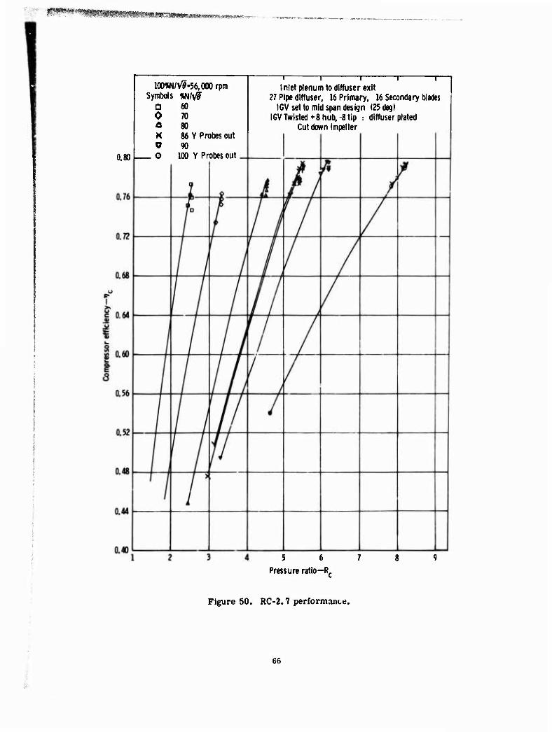
MHnMMWMHIMMHmnnMiww
100%N/V^-56.000 rpm Symbols vnl\/S
a 60 70 o
K y o
86 Y Probes out 90
100 Y Probes out
1 1 1 1 Inlet plenum to diffuser exit
27 Pipe diffuser, 16 Primary, 16 Secondary blades IGV set to mid span design (25 degl
IGV Twisted +8 hub, 8 tip : diffuser plated Cut down impeller
5 6 7
Pressure ratio—R,
Figure 50. RC-2.7 performanttj.
66
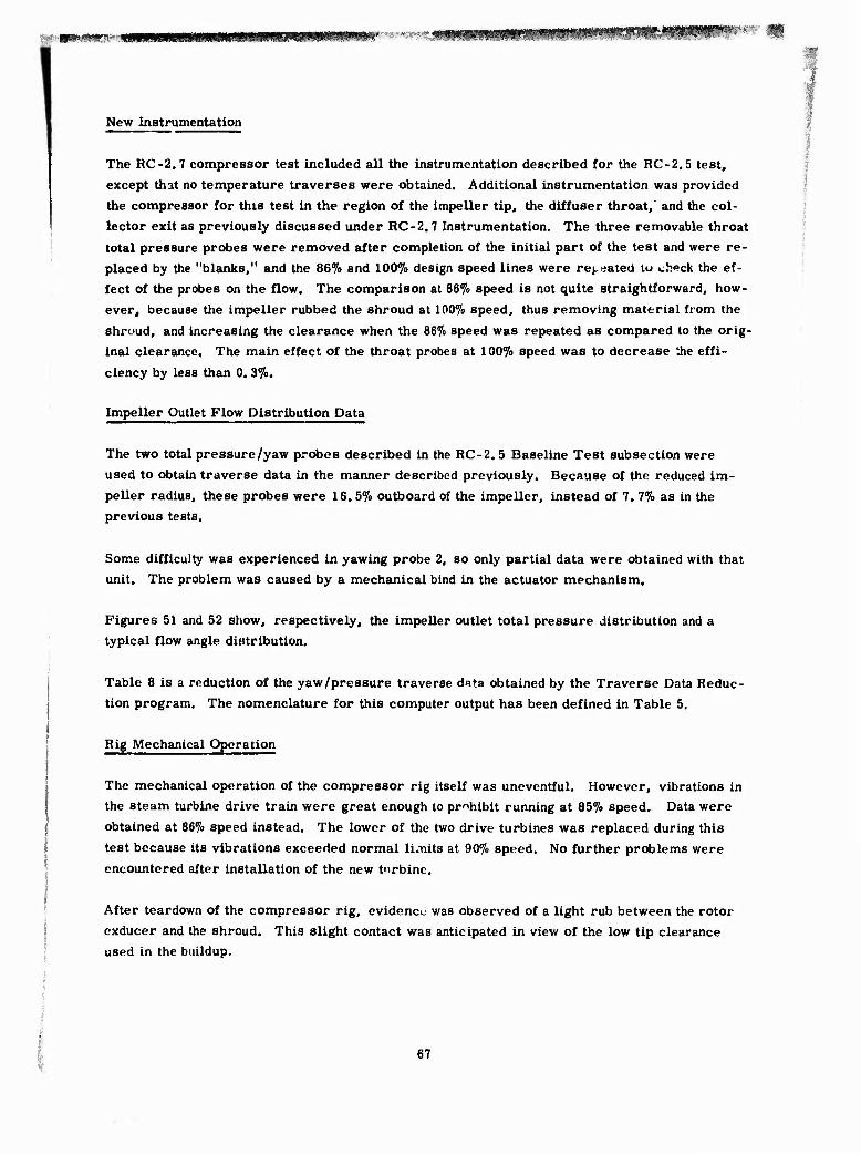
New Inatrumentation
The RC-2.7 compressor test included all the instrumentation described for the RC-2.5 test, except that no temperature traverses were obtained. Additional instrumentation was provided
the compressor for this test in the region of the impeller tip, the diffuser throat, and the col-
lector exit as previously discussed under RC-2.7 Instrumentation. The three removable throat
total pressure probes were removed after completion of the initial part of the test and were re- placed by the "blanks," and the 86% and 100% design speed lines were repeated lu check the ef-
fect of the probes on the flow. The comparison at 86% speed is not quite straightforward, how-
ever, because the impeller rubbed the shroud at 100% speed, thus removing material from the
shroud, and increasing the clearance when the 86% speed was repeated as compared to the orig- inal clearance. The main effect of the throat probes at 100% speed was to decrease the effi-
ciency by less than 0. 3%.
Impeller Outlet Flow Distribution Data
The two total pressure/yaw probes described in the RC-2.5 Baseline Test subsection were used to obtain traverse data in the manner described previously. Because of the reduced im-
peller radius, these probes were 16. 5% outboard of the impeller, instead of 7. 7% as in the previous tests.
Some difficulty was experienced in yawing probe 2, so only partial data were obtained with that unit. The problem was caused by a mechanical bind in the actuator mechanism.
Figures 51 and 52 show, respectively, the impeller outlet total pressure distribution and a typical flow angle distribution.
Table 8 is a reduction of the yaw/pressure traverse data obtained by the Traverse Data Reduc- tion program. The nomenclature for this computer output has been defined in Table 5.
Rig Mechanical Operation
The mechanical operation of the compressor rig itself was uneventful. However, vibrations in the steam turbine drive train were great enough to prohibit running at 85% speed. Data were
obtained at 86% speed instead. The lower of the two drive turbines was replaced during this
test because its vibrations exceeded normal lunits at 90% speed. No further problems were
encountered after installation of the new t'irbine.
After teardown of the compressor rig, evidence was observed of a light rub between the rotor
exducer and the shroud. This slight contact was anticipated in view of the low tip clearance used in the buildup.
67

RC-2.7
0.2 0.4 0.6 0.8 1.0
Axial dimension/Axial diffuser width
Figure 51. Impeller outlet total pressure profile.
RC-2.7
20 - ^
f 10
s
/ 0.2 0.4 0.6 0.8 \ .
-10 Axial di Tiens ion/Axial diffuser width s
Figure 52. Impeller cutlet flow angle profile.

IM'^VI«»
TABLE 8. YAW/PRF:SSURE DATA REDUCTION —HC-2/7.
!
RC 2.7 70» SPEED. RDG 627 INPUT DATA FOLLOWS
5 32.1960 30.6450 31.9440 33.0610 40.8000 784.3400 1*8640 32.0320 31.2200 31.5230 32.3700
215.^.000 55.3000 261.3000 101.4000 0.0000 39.8000 201.0000 436.5000 0*OOOC 44.5000 247.0000 441.5000 0.0000 46.8000 169.0000 495.0000 0*0000 47.5000 217.0000 471.5000 0.0000 50.4000 136.0000 565.0001 0.0000 51.2000 187.0000 513.0001 0.0000 50.8000 102.0000 569.5001 0.0000 50.5000 153.0000 504.5000 o.oooc 45.0000 64.0000 539.0001 0.0000 45.0000 110.0000 474*0000
47.9*60 0.1770 46.9350 0.3541 49.3110 0.3541 48.0440 0*3541 '♦5.4960 0.3541 42.8950 0.7C82 41.9440 0.7082 42*5860 0*7082 <K..3270 0.7028 0.0000 0.0000 0.0000 0.0000
INLET STATI ON P^OBE LEADING EDGE STATION PROBE
PTl 11 ALPHl PTLE 2U ALPHLE 39.8C00 0.0280 -6.0299 44.5000 0.0278 -7*6499 *.6.8000 0.0904 4.5000 47,5000 0.0863 -2.2500 50.4000 0.1548 17.0999 51.2000 0.1448 5.2200 so.esoo 0.2211 17.9099 50.5000 0.2111 3.6899 45.0000 0.2952 12.4200 45.0000 0.2950 -1.7999
INLET STATION DATA ON AVERAGE BASIS
I PT1B ALP1 PI Ml M2 CP 6 48,7784 13.7786 31.9473 0.8016 0.3930 0.5259
PT2B BL0C< WAC W/WMAX 0PT/PT1 P2 WA A»/A1 45.3845 C.1959 0.6912 1.0098 C.0b95 40.8000 1*8640 0*9548
LEADING EDO E DATA ON AVERAGE BASIS
I PT1B ALP1 PI Ml M2 CP 7 4R.5907 13.8257 31*7833 0.6029 0.3930 0*5364
PT29 BLOCK WAC W/WMAX DPT/PTl P2 WA A»/A1 45*3845 0.1959 0.6939 1.0137 0.0659 40.8000 1*8640 0*9516
RC 2.7 • 79.73 ( SPEEO. RDG 630 1 NPUT DATA FOLLOWS
5 39.7970 37.2260 39.4990 41.3770 51.4000 870.2900 2.3890 39.4550 38.0650 38*7880 40.1540
215.4000 55.3000 261.3000 101.4000 0.0000 52.9000 201.0000 476.5000 0.0000 0.0000 0.0000 0.0000 0.0000 64.3000 169.0000 533.5001 0.0000 0.0000 0*0000 O.OOOP 0.0000 „9.6000 136.0000 575.5001 0,0000 0.0000 0.0000 0.0000 0.0000 68.7000 102.0000 572.5001 0.0000 0.0000 0.0000 0.0000 0.0000 58.5000 64.0000 514.5001 0.0000 0.0000 0,0000 0.0000
60.3600 0.1770 59.1400 0.3541 61.1900 0.3541 59.4040 0.3541 59.7310 0.3541 53.8340 0.7082 53.2040 ü.'082 54.3860 0.7062 57.4380 0.7028 0.0000 0.0000 0*0000 0.0000
INLET STATION PROBE LEADING EDGE STATION PROBE
PTl 21 ALPHl PTLE ZLE ALPHLE 52.9000 0.0280 1*1700 0.0000 0.5095 -87.1199 64.3000 0.0904 11*4300 0.0000 0.5095 -87.1199 69.60C0 0.1548 18.9899 0.0000 0.5095 -87.1199 68.7000 0.2211 18.4500 0.0000 0.5096 -87.11*9 58.5000 0.2952 8.0100 0.0000 0.5095 -87,1199
INLET STATION DATA ON AVERAGE BASIS
I PT1B ALP1 PI Ml M2 CP 6 65.6673 13.4688 39*4500 0.8852 0.4022 0.4558
PT2B BLOCK WAC W/WMAX DPT/PTl P2 WA A»/A1 ä7.4599 0.1586 0.6931 1*0127 0.1249 51.4000 2.3890 0,9763
69
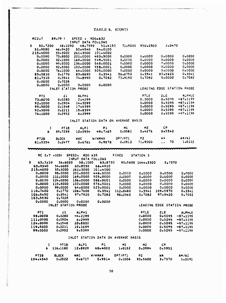
TABLE 8. (CONT)
«C2.7 89.79 ( SPEED • RDG.632 INPUT DATA FOLLOWS
5 90.7200 48.1090 48.7590 51.4130 71.9000 950.2600 3.047 0 51.9580 46.9420 50.4540 54*0100
215.4000 55.3000 261.3000 101.4000 0.0000 73.8000 201.0000 483.5000 0.0000 0.0000 0.0000 0.0000 0.0000 92.1000 169.0000 549.5001 0.0000 0.0000 0.0000 0.0000 0.0000 95.5000 136.0000 568.0001 0.0000 0.0000 0.0000 o.oooo 0.0000 92.5000 102.0000 558.0001 0.0000 0.0000 0.0000 0.0000 0.0000 76.1000 64.0000 505.0000 0.0000 0.0000 0.0000 o.oooo
85.5810 0.1770 83.6690 0.3541 86.8750 0.3541 63.8620 0.3541 81.7310 0.2541 74.6990 0.7062 73.9180 0.7082 0.0000 0.7082 0.0000 0.7026 0.0000 0.0000 0.0000 0.0000
INLET S'ATION PROBE LEADING EDGE STATION PSOBE
PT1 11 ALPMl PTLE ZLE ALPHLE 73.8000 0.0280 2.4299 0.0000 0.50^5 -87.1199 92.1000 0.0904 14.3099 0.0000 0.5095 -67.1199 95.5000 0.1548 17.6399 0.0000 0.5095 -87.1199 92.5000 0.2211 15.8399 0.0000 0.5095 -87.1199 76.1000 0.2952 6*2999 0.0000 0.5095 -97.1199
INLET STATION DATA ON AVERAGE BASIS
I PT1B ALP1 PI Ml M2 CP 6 69.7259 12*9954 49.7365 0.9581 0.4276 0.5542
PT2B BLOCK WAC W/WMAX 0PT/PT1 P2 w& A»/A1 81.5354 0.2477 0.6761 0.9678 0.0912 71.9000 .. 70 1.0112
RC 2.7 .100( SPEED. RDG 635 FIXED STATION 3 INPUT DATA FOLLOWS
5 63.3^10 56.6020 58.1000 63.8730 93.5600 1044.5300 3.7370 63.9340 54.6680 60*8550 66.4910
215.4000 55.3000 261*3000 101.4000 0.0000 96.0000 201.0000 446.5000 0.0000 0.0000 0.0000 0.0000 0.0000 111.0000 169.0000 505.0000 0.0000 0.0000 0.0000 0.0000 0.0000 124.0000 136.0000 586.0001 0.0000 0.0000 0.0000 0.0000 0.0000 119.5000 102.0000 576.5001 0.0000 0.0000 0.0000 0.0000 0.0000 99.0000 64.0000 523.0001 0.0000 0.0000 0.0000 0.0000
110.7400 0.1770 106*7600 0.3541 112.9480 0.3541 109.5970 0.3541 106.5450 0.3541 97*7920 0.7062 96.2360 0.7082 97.9420 0.7082 103.5530 0.7026
0.0000 0.0000 0.0000 0.0000 INLET STATION PROBE LEADING EDGE STATION PROBE
PT1 11 ALPMl PTLE ZLE ALPHLE 98.0000 0.0280 -4.2299 0.0000 0*5095 -87.1199
111.0000 0.0904 6*2999 0.0000 0*5095 -87.1199 124.0000 0.1548 20*8800 0.0000 0*5095 -87.1199 119.5000 0.2211 19*1699 0.0000 0.5095 -87.1199 99.0000 0.2952 9*5399 0.0000 0.5095 -87.1199
INLET STATION DATA ON AVERAGE BASIS
I PT1B ALP1 PI Ml M2 CP 6 116.1180 12*8929 60*4002 1.0132 0.3994 0.5951
PT2B BLOCK MAC W/WMAX 0PT/PT1 P2 WA A»/A1 104.4340 0.2022 0*6717 0.9614 0.1006 93.5600 3.7370 1.0191
70

I ■ I • -«W*!W;.«W!^?^^«^^
IV. COMPARISON OF THEORY AND EXPERIMENT
The teat data obtained for the RC-2. 5, -2. 6, and -2, 7 compressor builds were analyzed and
compared with the CCP calculation predictions. The calculation was then rerun with different
values of some of the input parameters in order to "match" the test data. The data matching
procedure was used to diagnose the compressor and to recommend modifications for the sub-
sequent tests.
DATA ANALYSIS
The compressor test data were analyzed to obtain the intrastage performance parameters. A
short discussion of each of the measurements and its analysis follows. For comparison pur-
poses, all pressure values were nondimensionalized by dividing by the compressor inlet (ple-
num) pressure.
DIFFUSER VANELESS SPACE
Inlet Static Pressure
This is the arithmetic average of eight static pressure taps distributed circumferentially so as
to span one diffuser passage at a radius 3% outboard of the original impeller and 11. 3% out-
board of the modified impeller used in the RC-2. 7 test. Half the taps were located on the hub
side of the compressor, and the other half on the shroud side.
Traverse Station Static Pressure
This is the arithmetic average of eight static pressure taps distributed as previously stated,
except that they were located at a radius 7. 7% outboard of the original impeller and 16.5%
outboard of the RC-2. 7 impeller.
Traverse Station Total Pressure
The "raw" value of this parameter is calculated from the data obtained in choke and as des-
cribed in the RC-2. 5 Test subsection.
A correction was then made to the raw value to reflect the value which the traverse data would
have yielded had the compressor been capable of stable operation at other than choked flow
conditions with the traversing probes in place. The correction is performed by multiplying
the raw value of the traverse pressure by the ratio of the maximum diffuser exit pressure at
the operating point in question to the same pressure at the "break" point at that speed. The
value of the break point pressure is illustrated in Figure 53. In the case of RC-2. 7, the value
71

of the throat total pressure readings c ulti ue substituted for the maximum diffuser exit pres-
sure; this method would give a result differing by less than 0. 2% from the method actually
used. The value of the traverse total pressure obtained in this manner is used in the calcu- lation of the pressure ratio. Mach number, and efficiency to the traverse stations of Tables
Si, 10, 11, and 12 shown later in this section.
The method of obtaining the operating point traver.se total pressure clearly involves the as-
sumption that only minor (and negligible) profile changes occur at the traversing station as
the compressor is loaded. Some substantiation for this assumption has been presented by
S. Baghdad!.1'
The Dilfuser Leading-Edge Static Pressure
The value of ♦his parameter is obtained by averaging the readings of four static pressure taps. Two of these pressure taps are located on the hub and two on the shroud side of the compres-
sor as illustrated in Figure 54. Because of the very large pressure gradients in tins region, the value of the leading-edge pressure obtained in this manner is felt to be accurate only to
within ±5%.
10
= 9
Filled symbols - Data points used In Tables V, 10, 11
K-2.1 Throat Pt (Ret!
o- • -Z0
o •—o
Break Point
Break Point
4.2 Correctei airflow -Wac
RC-2.6
4.4
Figure 53. Diffuser exit peak total pressure ratio—"Break Point".
" Baghdad!, S. A Study of Vaned Radial Diffusers Using Swirling Transonic Flow Produced
by a Vortex Nozzle. PhD. Thesis, I'urdue University, Lafayette, Indiana. December 1973.
72

■MMMMu .» ...__.._«_.___«~«»>»«»»™MI~«««I^'»W»W^^
The Diffuser Leading-Edge Total Prrasure
The diffuser leading-edge centerline total pressure read lower than the maximum diffuser exit static pressure throughout the RC-2 program. The other two loading-edge total pressure probes, which were in place and intact only for the RC-2. 5 test, appeared to read a realistic value. The
average reading of these two probes was used in Table 2. These probes were damaged in the
plating process used to decrease the throat area for the RC-2,ü tests and were not used.
The Diffuser Throat Static Pressure
♦All three centerline probes read within 1% of the average value.
7S
The value of this parameter is obtained by arithmetically averaging the readings of the static pressure taps distributed around the diffuser throat as shown in Figure 21. All seven of the
-i
tap readings were used in the RC -2. 6 data analysis; in the case of RC -2. 5 and -2. 7, however one of the taps was disregarded in the averaging as it read suspiciously high.
The Diffuser Throat Total Pressure
Diffuser throat total piessuie data were obtained only for the RC-2. 7 test, as previously dis- cussed. The arithmetic average of the readings of the three probes located at the centerline
of the three different diffuser passages was ust d* to obtain the diffuser throat centerline total pressure. The value of the area-averaged (or "one-dimensional") throat total pressure was then computed by multiplying the centerline total pressure by the blockage factor obtained from
a one-dimensional continuity calculation at the throat. This is the throat total pressure listed
in Table 11. ■
Impeller Tip Static Pressure
The RC-2. 5 and -2.6 builds did not have static pressure taps exactly at the impeller tip radius. It was therefore necessary to interpolate the impeller tip static pressure value from the radial
static pressure distribution measured along the shroud and in the diffuser. The arithmetic average of the five taps 4% radially inboard and the eight taps 3% radially outboard of the im-
peller tip were included in that distribution.
In the case of RC-2. 7, the arithmetic average of the live taps located at the new impeller tip
radius was used as the impeller tip static pressure

■waWRft 4HHi*Km*m/Bmmmmmmmmnmmmmmmfmm*mt* >' 11» «WWIU »»•^WWMW.'WMi' ww nvmimiK+w.vem*#if<
■rr-^
Section A - A
-^A
Figure 54. Leading-edge static pressure tap location.
APPLICATION OF CCP TO THE RC-2 COMPRESSOR
RC-2.5
Table 9 compares the predicted and measured values of the Intrastagr and overall compressor performance parameters. The predicted value of the rotor work, AH/H, is seen to be low by
tj.6% compared with the measured value. Two factors are of importance in understanding this
significant discrepancy. First, the CCP calculation had only recently been modified to ac- count for back-curved exducer blading at the time of the original prediction, and no substantial background for this type of compressor had been acquired. Second, the back-curved section
of the RC-2 impeller is an unusual, "no work" section added to the tip of a basically radial design. This approach led to rapid curvature changes in the exducer which, according to the
analysis of the test data, resulted in flow separation along the exducer pressure surfpces, (The slip factor works out to be greater than unity if the actual metal angle of 32. 5 deg at the
rotor exit is used.) The analysis of the test data indicates that, in actuality, the maximum
justifiable value of the effective blade exit angle is 28 deg.
Figure 55 compares the original slip factor prediction to the most recent computations used
in predicting the slip factor for RC-2. 7 as a function of the rotor exit blade angle. The most
recent theory produces a much higher value of the slip factor than did the original theory.
Table 9 shows that the CCP calculation was within 1% of the test data in its computation of the pressure ratio and flow rate, but that the calculated efficiency was 4. 5% higher than the
measurement.
74

■: ■MM aWWW^alltWWWWIWA'WOTIW'W'-W.tgarysa- r^r.iwr^iWMWW^m1«»^' ««,->.
TABLE 9, COMPARISON OF PREDICTED AND MEASURED VALUES—RC -2. 5.
Impeller
^traverse
^ adiabatic
^ hydraulic
''mixed AH/U2/Jg
Ctf/U
Impeller tip static pressure
Vaneless space
Inlet (1.03 R/RiT)
Ps/PTi PT/PTI
M
Traverse station (1. 077 R/Rj^)
Ps/PT PT/PT!
M
Diffuser
Leading edge
Ps/PTi
PT/PT!
M
Throat
Ps/PT, Exit
PT/PT!
Ps/PT! M
CPLE-exit
Ptraverse-exit Overall compressor (to diffuser exit)
AH/H
Wac
Re
Calculated Measured
0.863 0.834
0.890
0.940
0.864
0.763
0.780
3.716 3.640
4.290 4.028
9.777
1. 150
4.600 4.306
9.750 9.995
1.094 1. 166
4.895 4.231
9.542 9.468
1.025 1. 138
5.781
8.857 8.883
8. 138 8.018
0.350 0.385
0.700 0.723
0,687 0.653
1.048 1. 117
4. 184 4.230
0.825 0.781
8,857 8.883
75

RC-2.6 Actual
Curve for RC-2 in mode 2 or 3
Curve for RC-2 in model
'normal'
J Criginal estimate RC-2.5
0 10 20 30
Exducer blade anqle-deg
Figure 55. Variation of slip factor with exducer biaie angle.
RC-2,6
The RC-2. 5 test data indicatra that the diffuser inlet flow profile was weak on the shroud side
and that the inducer was choking at the maximum flow at design speed. For RC-2, 6, the first
of these problems was attacked by twisting tho inlet guide vanes—;i deg (oppn) at the tip, +8
deg (closed) at the hub—in such a mannor as to strengthen the shroud flow by re-distributing
the work at the impeller outlet. The second problem was tackled by plating the diffuser to
reduce the throat area by 3" ,
The data obtained during the RC-2, 6 t' sts are plotted together with the a priori (predicted)
CCP calculations in Figures 5ü and 57.
The a priori input to the CCP calculation involved a variation in the impeller axial blockage
input with speed which was similar to that deduced from the RC-2. 5 a posteriori analysis.
The change in the "flow quality" mode which was input for the 70"'.. speed line was likewise
anticipated from the RC-2.,ri data analysis. Figure fill shows that the CCP calculation success-
fully predicted the test data at all speeds except 100".,.
To match the lOO"!. speed test data a posteriori, the value of the impeller exit axial blockage
was increased over the value used a priori, and the diffuser choking coefficient was modified.
In addition, the flow quality mode of the rotor was changed from Mode 1 to Mode :j, indicating
76

Qf"' HMprah.'^Wi
9
8
7
6
5-
4-
3
RC-2.6
Symbols: Test data ——Calculation (a priori)
^S
o
100% N/V^
•«x^ 90% ^ x
86%
2i 80%
70%
1.6 2.0 2.4 2.8 3.2 3.6 4.0 4.4 Corrected airflow-Wa
Figure 56. Predicted and measured performance—RC-2.6.
RC-2.6
Symbols: Test data
—^^— Calculation (a priori)
0.9
0.8
0.7 i.
70% 80% 86% 90% 100% wye '
2.0 2.4 2.8 3.2 3.6 4.0 4.4 4.8
Corrected airflow—War
Figure 57. Predicted and measured performance—RC-2.6.
a degraded rotor performance. These changes result from the fact that the RC-2. 6 rotor with
the twisted IGV's b' 1 wed similarly to the RC-2, 5, .^3 deg IGV setting instoad of similarly to the 17 deg setting as .nticipated. In other words, it would appear that the hub value of the
IGV setting dominated over the tip value.
Table 10 compares the a priori calculated and measured values of the intrastage and overall
performance parameters of RC -2,6 near the design point. This table hows that the calcu-
lation was within 0, 1% of the measured pressure ratio, but was 1, 5% high in efficiency and
6,6% high in flow.
77
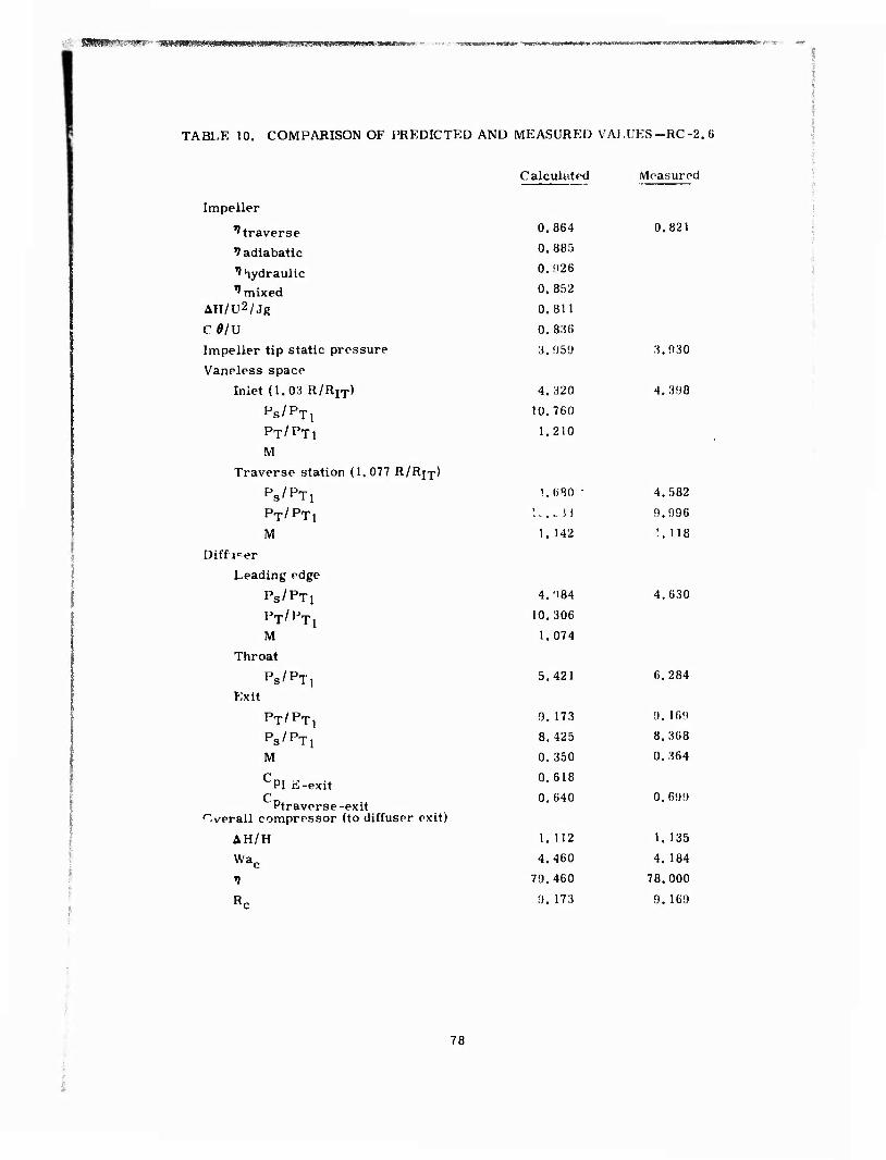
1 BMMWHW WKmtmmmmm
TABLE 10. COMPARISON OF PREDICTED AND MEASURED VALUES—RC-2.6
Calculated iVloasurod
Impeller
^traverse
V adiabatic
V hydraulic
^ mixed AH/U2/Jg
CÖ/U
Impeller tip static pressure
Vaneless space
Inlet (1.03 R/R1T)
Ps/PT! PT/PTl
M
Traverse station (1.077 R/Rj^)
Ps/PT!
PT/PTI M
Diffuper
Leading edge
PS/PTi PT/PT1
M
Throat
Ps/PT! Exit
PT/PTl
1 Ps/PT M
C PI ii-exit
Q Ptraverse-exit
overall compressor (to diffuser exit)
AH/H
Wac
1
R.
0.864
0. 885
0.926
0. 852
0.811
0. 836
3.959
4. 320
10.760
1.210
4.984
10.306
1.074
5,421
0.821
3,930
4.398
L6S0 • 4. 582
.. . H 9.996
1. 142 '.. 118
4.630
6.284
9, 173 9. 169
8.425 8.368
0.350 0.364
0.618
0.640 0.699
1. 112 1. 135
4.460 4.184
79.460 78.000
9. 173 9. 169
78

■'■"'-■■■gl*
-
RC-2.7
The analysis of the RC -2. 5 and -2. 6 data indicated that the rotor outlet flow deviated (i. e.,
was separated) from the pressure surface in an unusual manner. This deviation was ascribed to the rapid curvature used in the exducer design, so the back-curved portion of the exducer
had to be removed to remedy the situation. This modification entailed the insertion of an ex- tended vaneless spaoe to replace the outboard 8% of the rotor which was removed, so the dif-
fuser leading edge was now 22% outboard of the rotor tip.
The predicted and measured values of the UC-2,7 performance (both overall and intrastage)
near the design point are shown in Table 11. The calculated value of the mass flow in Table
11 is that which yielded the maximum overall efficiency. However, the program showed very
little variation of the overall efficiency with flow rate, so the a priori calculated performance
at the increased flow rate differed significantly from the value shown in Table 11 only with respect to the diffuser throat static pressure and Mach number. The calculation is seen to be
high by 3. 6% in flow, 0. 7% in efficiency, and 1. 78% in pressure ratio.
The adjvstment required to "match" the calculation to the test data consisted of varying the
diffuser choking coefficient; this change lowered the pressure and shifted the compressor's choke fljw to a lower value. The resulting map is compared to the test data in Figures 58 and 59. The only aerodynamic program input which is varied with speed is the diffuser choking
coefficient. If an average value of this coefficient were used*, the maximum deviation from the data resulting would be ±l^r in efficiency and ±2% in pressure ratio. The computer runs used to produce Figures 58 and 59 are shown in the Appendix, together with the input-output
nomenclature. The compressor running clearance, which is included in the rotor hub to
shroud dimension BH, is input, and varies with rotor rpm. 'i—
7 s s E 6 •3
I
■ Calculation (Design point data match) Symbols: Test data, RC-2.7
- Test data surge line, RC-2.7
0.8
0.7
0.6 U
c
S 0.4
0.3
4*% o* a* "^ n
- r
a O
i i ,._ i i i.i i i 1
.8 1.2 1.6 2.0 2.4 2.8 3.2 3.6 4.0 4.4 4.)
Corrected airtlo«»-Wac
Figure 58. Measured and matched performance—RC-2.7.
1.2 1.6 2.0 2.4 2.8 3.2 3.6 4.0 4.4
Corrected alrtlow-Wa,.
Figure 59. Measured and matched performance—RC-2.7.
♦Obviously, until a more accurate diffuser choking relationship is found, the a priori or design
mode of the program will use such a constant coefficient.
79
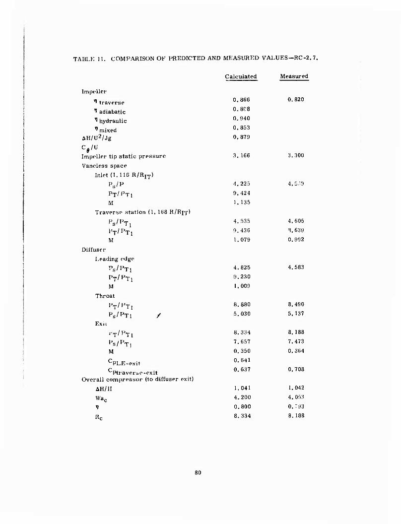
TABLE 11, COMPARISON OF PREDICTED AND MEASURED VALUES-RC-2. 7.
Calculated Measured
Impeller
I traverse
1 adiabatic ^ hydraulic ^ mixed
AH/U2/Jg
0.866
0.8C8
0.940 0. 853
0.879
0.820
Cfl/U Impeller tip static pr essure 3. 166 3.300
Vaneless space
Inlet (1. 116 R/R IT) Ps/P 4.225 4.5;'.9
PT/Pn 9.424
M 1. 135
Traverse statior (1 168 R/RJT)
Ps/PTj 4.535 4.605
PT/PTl 9.436 !).639
M 1.079 0.992
Diffuser
Leading edge
Ps/PTl 4.825 4.583
PT/PTI 9.230
M 1.009
Throat
PT/PT! 8.880 8.490
Ps/PTl / 5.030 5.137
Exu
rT/PTl 8.334 8. 188
PS/PT, 7.657 7.473
M 0.350 0.364
CPLE-exit
Ptraver&e Overall compressor
■exit (to diffuser exit)
0.641 0.637 0.708
AH/H 1.041 1.042
Wac 4.200 4,053
1 0.800 0.:93
Re 8.334 8. 188
80

«««.»<iswj»r- K«K'f>emms*W^i^^f:'-
DISCUSSION
Tables 9, 10, and 11 may be interpreted to indicate that the CCP program has difficulty in sep-
arating thp subcomponent performance. The reason for this may be the very complex rela-
tionship between the impeller and the diffuser.* Table 12 lists the measured subcomponent
efficiencies of the various RC-2 configurations. The pressure ratio at the traverse station
for the 17 deg IGV setting of RC-2. 5 was not measured, and is deduced by comparing the lead-
ing-edge total pressures to those of the 25 and 33 deg IGV settings of this build. Table 12 indi-
cates that, when the IGV's were twisted, the impeller efficiency was reduced and the diffuser's
•-future recovery coefficient increased. This increase in the diffuser perfon.u.nce can be at
k .ist partly traced to the improvement in the impeller outlet flow profile which in turn can be
traced to thf* work redistribution effect of twisting the inlet guide vanes. Sine improving the
flow profile into the diffuser was the motivation for twisting the inlet guide vanes, this result
was expected. Unfortunately, the loss in impeller efficiency was not expected. The explan-
ation for the decrease in Impeller performance in going from RC-2. 5 (25 deg IGV) to RC-2. 6
cannot be explained solely in terms of an Increased inducer tip Mach number, for the RC-2. 5,
17 deg IGV build, which has the highest impeller efficiency listed Its Table 12, also has the
highest inducer tip Mach number. In fact, the only parameter that (separates the higher effi-
ciency impellers (RC-2. 5, IGV = 17 deg and IGV-25 deg) from the lover efficiency impellers
(RC-2. 5, IGV=33 deg, RC-2. 6 and RC-2. 7) is the hub value of the inlet guide vane setting,
which was 33 deg for the lower efficiency rotors and 17 and 25 deg for the high efficiency
rotors. The differences in rotor efficiencies can thus be tentatively attributed to a sensitivity
to the inducer inlet flow iacidence profile.
TABLE 12. INTRASTAGE EFFICIENCIES OF VARIOUS RC-2 CONFIGURATIONS.
RC-2.5 RC-2.6 RC-2.7
j Impeller
IGV = 17 IGV = 25 IGV = 33 IGV = 25 IGV = 25
i Inducer tip Mach No. 1.220 1.112 1.034 1.218 1. 191
■ Rctraverse 10.431 9.995 9.541 9.996 8.639
I ^ traverse 0.840 0.834 0.823 0.821 0,820
} Mtraverse 1. 170 1.166 1. 181 1. 118 0.992
1 Diffuser
1 CPtraverse-exit 0.C43 0.653 0.651 0.699 0.708
I Rc exit 9.187 8.883 8.399 9. 169 8. 188
; Mexit 0.383 0. 385 0.376 0.364 0.364
• Ciall
0.780 0.781 0.767 0.780 0.793
*The vaneless space up to the traversing station is considered to be part of the impeller, since
this is the performance measuring station closest to the rotor.
81

r^t>>-: ■ ' '-'■ '■■^*!!^*!'?*iiSi»^i!8w«ssss^^ ■
It is important to note that the "impeller" efficiencies listed in Table 12 actually include losses
up to the traverse station. Thus, the actual impeller efficiency (not including vaneless space losses) must have increased in RC-2. 7 as compared to RC-2. C, because the traverse station is 13% outboard of the impeller in the former case and only 7.7% in the latter,* This is im-
portant because it implies that the removal of the bent back section of the rotor decreased the
rotor losses, thus lending credibility to the theory that the exducer pressure surface was sep-
arated in RC-2. 5 and RC-2. 6. In fact, the a posteriori CCP calculations show the rotor loss to have decreased from 50. 9% of the total losses in RC -2. 6 to only 38. 4% in RC -2. 7.
The RC-2. 7 compressor showed an efficiency improvement c? 1. 3% in spite of the fact that the diffuser leading edge was 22% outboard of the modified impeller. If the current design
practices at DDA and elsewhere can be used as a guide (ref: D. P. Kenny*, an ASME publica- tion,' and D. P. Kenny *" ), the RC-2. 7 radius ratio is excessive—the optimum radius ratios
used vary from 5% to 13% for high-pressure-ratio machines. Thus, a further efficiency im-
provement may be realized if the modified rotor were tested with a new, rematched, smaller
raums ratio diffuser. However, the magnitude of the improvement is difficult to assess with- out recourse to a performance prediction calculation (such as CCP) which takes into account
both the decreased losses due to the lower leading-edge Mach number and the increased "fric- tional" loss because of the large vaneless space radius ratio. Contrary to expectations, the
CCP calculation does not show a performance decrement in the case of this particular diffuser
as the leading-edge radius ratio is increased from 1,13 to 1. 22. Because of the lack of suffi- cient test data at the higher radius ratios, only a specific test can confirm the CCP prediction in +his regard.
^Obviously, this comment assumes that the losses in the vaneless space are proportional to the extent of the vaneless space.
•'Kenny, D.P. A Comparison of the Predicted and Measured Performance of High Pressure
Ratio Centrifugal Compressor Diffus eis, ASME Paper No. 72-GT-54. 1972.
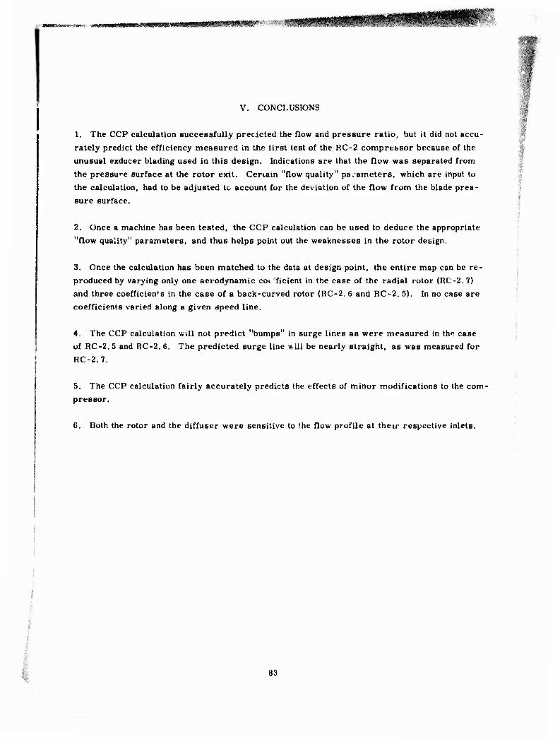
MV3m>mgmmm«s^immi0^»te0!Sff!^SS!S^WW^^^'
V. CONCLUSIONS
1. The CCP calculation euccessfully precicted the flow and pressure ratio, but it did not accu-
rately predict the efficiency measured in the first test of the RC-2 comprebsor because of the
unusual exducer blading used in this design. Indications are that the flow was separated from
the pressure surface at the rotor exit. Cenain "flow quality" parameters, which are input to
the calculation, had to be adjusted to account for the deviation of the flow from the blade pres-
sure surface.
2. Once a machine has been tested, the CCP calculation can be used to deduce the appropriate
"flow quality" parameters, and thus helps point out the weaknesses in the rotor design.
3. Once the calculation has been matched to the data at design point, the entire map can be re-
produced by varying only one aerodynamic co«. rficient in the case of the radial rotor (RC-2. 7)
and three coefficients in the case of a back-curved rotor (RC-2. 6 and RC-2. 5). In no case are
coefficients varied along a given speed line.
4. The CCP calculation will not predict "bumps" in surge lines as were measured in the case
of RC-2. 5 and RC-2. 6. The predicted surge line will be nearly straight, as was measured for
RC-2. 7.
5. The CCP calculation fairly accurately predicts the effects of minor modifications to the com-
pressor.
6. Both the rotor and the diffuser were sensitive to the flow profile at their respective inlets.
83

VI. RECOMMENDATIONS
1. The diffuser IOöS models used in the CCP calculation should be updated to take into account
the recent data of References 3 and 4.
2. An effort should be directed toward finding a relationship between the impeller "flow qual-
ity" and the blading distribution; in particular, a relationship is required that would express the
rotor "flow quality" in terms of the gradients in the impeller blade angle distribution and cer-
tain diffuser parameters. Such a relationship would obviate the necessity for inputting the "flow
quality" into the calculation.
3. The HC-2.7 rotor should be equipped with n properly matched diffuse, and tested lor per-
formance to ascertain the compressor's true potential.
84

nemmtmr-to**''' ■
VII. REFERENCES
1. Balje, O.E. A Study on Design Criteria and Matching of Turbo Machines. Part B—Com-
pressor and Pump Performance and Matching of Turbo Components. ASME Paper 60-WA- 231.
2. Kenny, D. P. A Novel. Low-Cost Diffuser for High Performance Centrifugal Compressors. ASME 68/GT-38.
3. Dean, R. C,, Jr., and Runstadler, P. W,, Jr. Straight Channel Diffuser Performance at High Inlet Mach Numbers. Creare, Inc., Hanover, New Hampshire.
4. Dolan, F. X., and Runstadler, P. W., Jr. Pressure Recovery Performance of Conical Dif- fupers at High Subsonic Mach Numbers. Creare Report TN-165, Hanover, New Hampshire. July 1973.
5. Rodgers, C. A Cycle Analysis Technique for Small Gas Turbines; Technical Advances in Gas Turbine Design. Paper No. 5, Institution of Mechanical Engineers. April 1969.
6. Advanced Centrifugal Compressors. ASME Turbomachinery Committee, Gas Turbine Di-
vision, New York, 1971.
7. Dallenbach, F. The Aerodynamic Design and Performance of Centrifugal and Mixed-Flow
Compressors; Symposium on Centrifugal Compressors. ASME. 1962.
8. David, D.M. Radial Flow Co'tipressor and Turbine Design Program. Mathematics Sciences
Report. Detroit Diesel Allison Division, General Motors. August 1971.
9. Stanitz, J.D. Some Theoretical Aerodynamic Investigations of Impellers in Radial and Mixed- Flow Centrifugal Compressors. Trans, ASME, Vol 74, pp 473-497. 1952.
10. Katsantis, T. Computer Program for Calculating Velocities and Streamlines on a Blade-to- Blade Stream Surface of a Turbomachine. NASA TN D-4525. April 1968.
11. Hopkins, B. A. Inlet Guide Vane Design for Certrifugal Compressor. Research Note RN
69-79, Detroit Diesel Allison Division, General Motors. Dec mber 1969.
12. Morris, R. E., and Kenny, D. P. High-Pressure Ratio Centrifugal Compressors for Small Gas Turbine Engines. Report No. 6, 31st Meeting of the Propulsion and Energetics Panel
of AGARD, Ottawa, Canada. June 1968.
85
-■■.*a**n,<**»- >.^.„.^ —aMI 1 ir iiiiiinj.—ill.. *T«^,V
13. Trent, R, Dynamic Analysis RC-2 Compressor Rotoi Ca^e System. Engineering Depart-
ment Report TDR AX. 0220-016, Detroit Diesel Allision Division, General Motors. June
1972.
14. Burns, L. Vibration Analysis of the RC-2 Impeller. Engineering Department Report TDR
AX. 0201-037, Detroit Diesel Allison Division, General Motors. July 1972.
15. Clute, M, Stress Analysis of the RC-2 Impeller. Engineering Department Report TDR AX. 0201-036, Detroit Diesel Allison Division, General Motors. July 1972.
16. Colborn, J.H. Temperature Distributions in the RC-2 Impeller. Engineering Department
Report TDR AX, 0201-035, Detroit Diesel Allison Division, Gmeral Motors. May 1972.
17. Flow Measurement. ASME Power Test Code Committee, ASME, New York. 1959.
18. Keenan, J. H., and Kaye, J. Gas Tables. John Wiley and Sons, Inc., New York. 1961.
19. Raghdadi, S. A Study of Vaned Radial Diffusers Using Swirling Transonic Flow Produced
by a Vortex Noazlo. Ph. D Thesis, Purdue University, Lafayette, Indiana. December 1973.
20. Kenny, D. P. A Comparison of the Predicted and Measured Performance of High Pressure
Ratio Centrifugal Compressor Diffusers. ASME Paper No. 7?-GT-54. 1972.
86
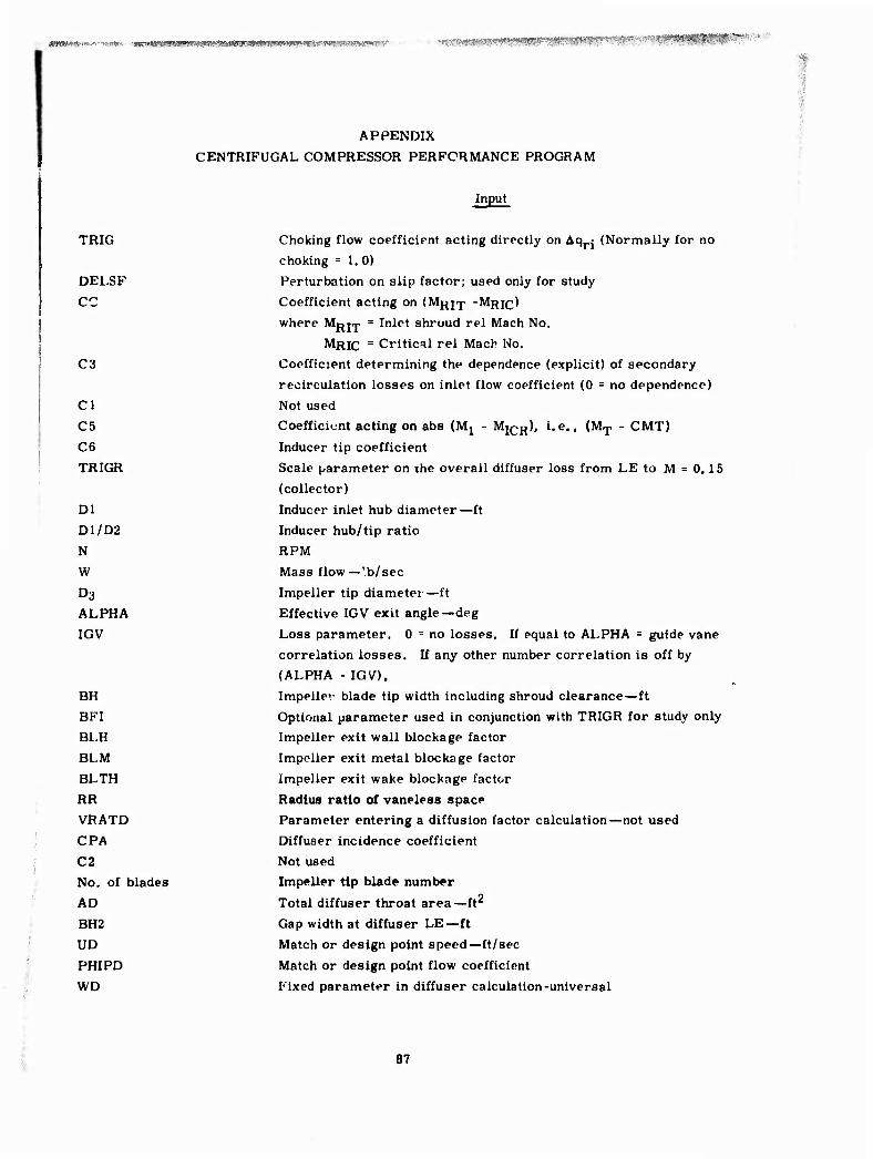
««»wsf-;«'.'--'»»^ j^^Bira—WH*^^«*:*;-' 'XfffäeimW! ■
TRIG
DELSF
CC
C3
Cl
C5
C6
TRIGR
Dl
D1/D2
N
W
D3 ALPHA
IGV
APPENDIX
CENTRIFUGAL COMPRESSOR PERFCRMANCE PROGRAM
Choking flow coefficient acting directly on Aqrj (Normally for no
choking =1.0)
Perturbation on slip factor; used only for study
Coefficient acting on (Mp^j-p -MRIC)
BH BFI BLH BLM BLTH RR
! VRATD CPA
: C2 .- No. of blades
i AD ■ BH2
• UD 1
- PHIPD WD
where Mi RIT Inlet shroud rel Mach No. MRIC - Critical rel Mach No.
Coefficient determining the dependence (explicit) of secondary
recirculation losses on inlet flow coefficient (0 = no dependence)
Not used
Coefficient acting on abs (Mj - MjCR), i.e., (MT - CMT)
Inducer tip coefficient
Scale parameter on the overall diffuser loss from LE to M = 0.15
(collector)
Inducer inlet hub diameter—ft
Inducer hub/tip ratio
RPM
Mass flow—'b/sec
Impeller tip diameter—ft
Effective IGV exit angle—deg
Loss parameter. 0 = no losses. If equal to ALPHA = guide vane
correlation losses. If any other number correlation is off by
(ALPHA - IGV).
Impellev blade tip width including shroud clearance—ft
Optional parameter used in conjunction with TRIGR for study only
Impeller exit wall blockage factor
Impeller exit metal blockage factor
Impeller exit wake blockage factor
Radius ratio of vaneiess space
Parameter entering a diffusion factor calculation—not used
Diffuser incidence coefficient
Not used
Impeller tip blade number
Total diffuser throat area—ft2
Gap width at diffuser LE—ft
Match or design point speed—ft/sec
Match or design point flow coefficient
Fixed parameter in diffuser calculation-universal
87

ALPS C7
C8
C9
CIO
en C12
C13
RNMCR
CMT
Diffuser LE mean blade angle from tangential—deg
Diffuser parameter acting on CQ PQ^E/ PTTHT ^S ^DLE curve
Coefficient entering equation of blockage influence in the impeller on secondary losses
First-order incidence coefficient for diffuser. Same value for all pipes
Diffuser incidence parameter describing the transition from sub-
sonic to supersonic Universal factor on friction formula in the vaneless space Factor entering calculation for negative incidence loss on inducer
Factor entering calculation for inducer tip incidence effect on wall blockage
IrJucer t'p relative critical Mach No. 0. 87 is the state-of-the-art
number
Critical absolute inlet Mach No. acting on 1GV and inducer
Output
POP PRTTE
HE
W/A
MT
GG RHOS MAX PHI
AI VT CTHT
BETAG PHIP
First column of subprints (Without incidence)
(With incidence) The remaining subprints are
URMS
Rotor inlet total head pressure aftei IGV losses —lb/ft2
Total/total pressure rise inducer tip to exducer tip in the rotor
(before mixing) Euler head = U2/gJ Flux entering rotor with fixed standard 0.985 blockage factor-
lb/ft2
Abs Aute inducer inlet Mach No., max when there are no IGV y-i o.
(1 + MT'2) Static density —lb/ft-5
Axial component of MT vaxiai (referring to MT)/U(imppüer exit tip) = flow factor Sonic speed at MT—ft/sec Absolute velocity at MT—ft/sec Tangential velocity at inducer RMS—ft/sec
Gas angle at inducer tip—deg Inducer inlet flow coefficient V^gg/Upj^jg
Gives top column CQ X PDLE/TTHRT
Bottom column CQ X PDLE/TTHRT
calculation check points.
Inducer speed at RMS—ft/scc
88

^VflM'— 'WNM sHMMMHi
PF
PSI
EFFH
DQ
RNMIT
T04
T03D
T03
P03
U
DRMS
EPS
CSF
PRDLE
CPT35
RC 35
ET 35
DP 35
DPQ
PSTH
ETS
NS
RCS
MEXIT
MDLE
DQX
TRF
EFFI
DPOP
PSLE
DIBF
EFFM
MG
MDEX
DP'.'D
AL PHD
Prewhirl factor at URMS normalized to Hül
Rotor overall total/total pressure coefficient related to PRTTE
Rotor isentropic efficiency just before dump
Internal loss coefficient normalized to HE
Rel inducer inlet tip Mach No.
Total discharge temp of diffuser—°R
Total temperature dumped at impeller tip—0R
Total temperature at impeller tip before dump—°F
Total pressure at impeller tip—lb/ft
Speed at impeller tip—ft/sec
Inducer RMS diameter—ft
03/DRMS
Slip factor at impeller tip
Pressure ratio total/total diffuser LE
Diffuser static recovery throat to exit (M = 0. 35)
Pressure ratio total/total at diffuser exit (M ■ 0.35) to ambient
Overall compressor efficiency total/total at discharge (M = 0,35)
/AP, from diffuser LE to exit
from diffuser LE to throat
(- \PT /0.35 AP (static)
Static pressure ratio at throat as referred to ambient
Total-to-static efficiency based on given collector dump loss
Specific speed
Pressure ratio diffuser exit static to ambient
Correlated guess as an iteration helper to calculate MDEX
Mach number at diffuser LE
External loss coefficient normalized to HE
Rotor work coefficü ;it — enthalpy rise across impeller normalized
to ambient stagnation enthalpy
Impeller adiabatic efficiency (unmixed) including IGV losses
Total pressure loss in vaneless space normalized to impeller
tip total head pressure
Static pressure ratio at diffuser LE normalized to ambient
Blockage factor in vaneless space M BH2 (not including metal)
Rotor efficiency after mixing at diff 'r LE (includes vaneless
space loss)
Mach Nu. in rotor just before dump
Mach No. (dumped)
AP0/Po (dump loss)
Mean gas angle from tangential as dumped—deg
89
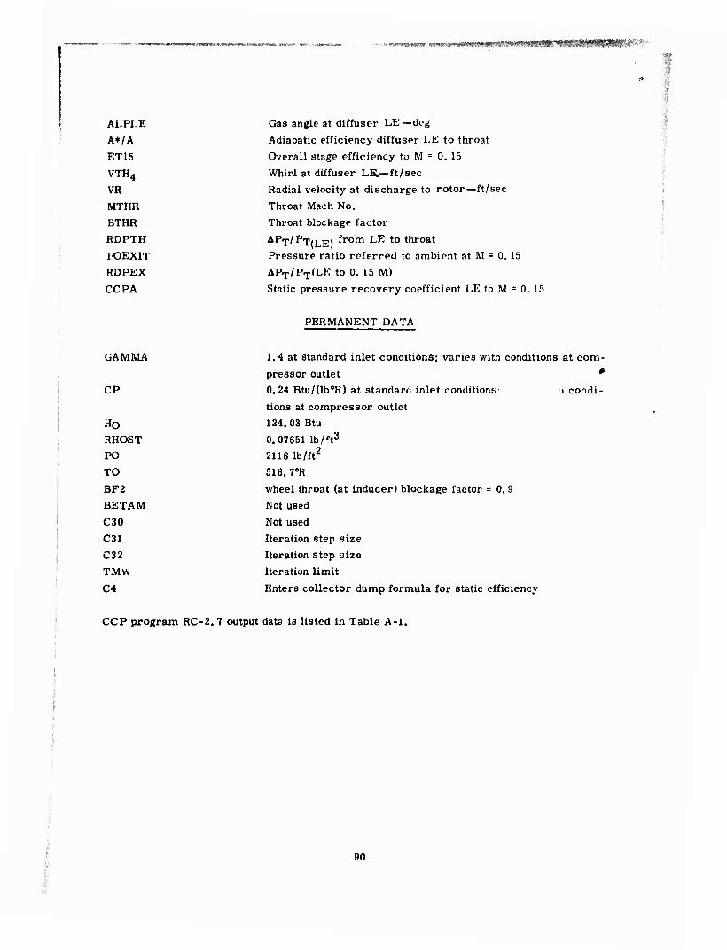
* .^fyggt-l ——ll ( iKi<9mmmmmm^^mimmmfr^m-^J^^fS&'>sf''-i ;i' ■ ■^
ALPLE
A*/A
ET15
VTH4
VR
MTHR
BTHR
RDPTH
POEXIT
RDPEX
CCPA
Gas angle at diffuser LE—deg
Adiabatic efficiency diffuser LE to throat
Overall stage efficiency to M - 0. 15
Whirl at diffuser LK.—ft/sec
Radial velocity at discharge to rotor—ft/sec
Throat Mach No.
Throat blockage factor
APT/P-J-,, JJV from LE to throat
Pressure ratio referred to ambient at M = 0, 15
APT/PT(LE to 0. 15 M)
Static pressure recovery coefficient LE to M = 0. 15
PERMANENT DATA
GAMMA
CP
HO RHOST
PO
TO
BF2
BETAM
C30
C31
C32
TMW
C4
1.4 at standard inlet conditions; varies with conditions at com-
pressor outlet *
0.24 Btu/(lb0R) at standard inlet conditions; i condi-
tions at compressor outlet
124.03 Btu
0.07651 lb/n3
2116 lb/ft2
518.70R
wheel throat (at inducer) blockage factor = 0. 9
Not used
Not used
Iteration step size
Iteration step size
Iteration limit
Enters collector dump formula for static efficiency
CCP program RC-2. 7 output data is listed in Table A-l.
90

l|ll!l,«IH^J.#||^||Wl.nWWI,«l^ ■jJT».* t™^^ '^>P?WWWWPI!|iaP|WPB^BPip^pprBg^'WJWgW9FTJ^¥^gT?w^ ,jvin;»w».Wi.gmA-,-^-q??t»-.
*«■- HI
<
< Q
H P a. H
O
O K
< a o g (X
a. u o
I
< W
<
•# ■i a* e o e o O e o
•c 1 t- UlU Ul lii 5S lb
s§ ZN r-o KO C* M o m ♦ « «
H- Vt » U o ♦ X M «« (M o ■« M\ Wl • • • « • • O o o o o o
M IM M o e o o
1 o o o
1 u. Ul t£ o. ix a u. UJ
«e 5§ 0.0 _lO i~o V>x
u «> « ♦ SO i5 <B «-M oo « zt- K> M ■rt •— «r« B« • • • • ■ • O O o o o o
-< N o o m4 -* o o O o o O
m i o o
lu m oiu li. — UJ aj w mo «o K O CO uo M a. o «-> o xo «O sir o a-e
w a «M at o » o ISO I •-• IM -fi > « c IT. m a. «
s o ^ O o o o o o e o
o « inui IT Ul «nu> Ul nui a ui or- miM u*- u.« wr» <■»;£ ^«n ►- m ef • o •- «0 o'-
o a » m* — «n uiir »4 u -o *■ o« K •0 • • • o o o o o o
% m^ rs. «4 ** O O o O o o
* u. « » O Ul ^ u. WIU. Ul Ul ««. Ul UlUi ►-« om 2 " -i« •^ ••? s ae o »> MfM « •* ej«M
a o Al a ^- ♦ " 12 o Q- ♦ ♦ • • • • • • o o o O o
i o
** o o IM _
o o o o ul O »-o t- 1 .J »■ •"OJ L. H, 1/1 u. a If a u. >i UJ z o V> (V >- « c ■* _|0 U, 4> z » %.' •r UlO a •e «f- o~ a o o m e» eo a -o
p4 0- ^- *- •— ^
M o «^ o ■4 o IM O o o o o o O
1 Ul Ul Ul C Ul IMU1 111 u.
— o mo a — a o — c 1- IT O IT <-> o C1M or IM — ir uo X <e < f
o IT IM TIM IT IA ir 1- — * « *•* a « * 1- m Ul « o o * • • • ■ _i • c • o o o o o o c D
in o o o o
o o
CM -• o
1 o O O o
o O
X 1 O Ul IA Ul Z ui M Ul I Ul ►- Ui c »- & K l-O u. N a o a o
w Ui fr «IK U. 1- _lO o ■» or » a ir u. «j « « a o in 4 CD -4 *
o o
IM I u a
u «
o u
w4 •M o * Mi
O o o o O
Ul ^ u. u. ai l»l o air I o c cc -" O o O M 1- o D *rt -■ O
IM «4 •11« c oir. «4 ■r BK -4 <o • • • • • o o o c o
-rf ir o >■ o o o o »5
«.; Ul Ul UJ M t
Ul Ul CJ o z » T C I c o
o a _ o It c OO o w » * c - c IV tf- » ^, u --
X ui 0"
o o «M n o o o o
u 1 1« Ul u C ui Ul -1 MO T O « o a '■ Ul O l" JO u o (1 V « K ir «r IT
■5 — ♦ » • e . • • a o o o o
VI Ul
O
o C M •* o o •I o o
O Ul ~* U' m u 00 Ui — o c o IM o oo a o o U li. o tf >- o o C C IM o
IM o m ■1
• • • o • • o o o z o o
Ui o o •- a o o I IT « 4) k- (M • • U IM O O
IM ^• 1*1 O O f» • •
n o Ui
IM »- o < « > * f I«1
• IM CM O K r- • • o o
O 4. 4i ir ir
u' « <r m « a,
— oo ♦ • < o o o
o o pM ^ »^ o c o c o o o
z 1 c i U Ul if Ui ou u u *- b- u. u U IM z < a ir a o a O I — Ui C a * e » »- 4 c 1** »- —
1*1 c m « « c a r- a i^i ■t OC IM o- • • • • « • c o 3
1 o o o
15 Z
o * O ■M —* o 3 o O c -> o o z IT 1 M
*• Ul u !«• U. X IA. Ul Ul a u. ►- in m a m Cl^ e o I » 2 a 4 3 M4 c •» c & T (—« » a C a o o o tr\ 1 z <J K --
■1 — Q-
CM ■*
» a • •* o • • • o o o o •
a. C Ui — UJ Ul a. K I m K
oo a IM < oo c a ir — z o
IN IM ^ l«l O « . o. o o o • « »
o o • •
t. ^• IT o «Ml mm (*■
u. O o c o o o V 1 tf Uu u u f u f»- UJ u. w 4^ L.
& C ^ t- a ,J If t? ■0 f * » O a in UJ If c o r a. > 1- •^ o a » c m <T 7 « f\P ^- ■M * UJ • • • • • • V o O o •^ o O
<
OL D m J -^ O ^ X
un o o
IT o h o X o
u. X if r U' C« U' > UJ u. u> T H
5 f^ c •« <- IT u <£ u ~* »- P c * h IS a •c > r- u. o > a ac «0 O c rg f «0
< a« a ~* a «■*
< I-
91

o s
o I
UJ I «M CD ♦
o
F- e o
IT
o
o o
K ♦ « ♦ s —
in • o
« e ■4 e o o o o o o 6 e
r; r« 11 u. VI tu */> Ifci Ui lOUl a lb Cf- m»« w ss •^ M u« ►- m h- -• ce - K M 0m
o a m a — in UI « « •■4 o-o r- cc K <e • • . • • • o o o o O o
(M INJ m* (Si o — O o O
1 o
1/1 o o
1 kj UJ 1*1 0. u. a ib lb
«Cl > o « o -<o u o i/i r- u«- oo 0.O <•* a o o»
CD — rj oo « r K I * ir m ac« a « • • • • • • o o o o o o
s ^t (NJ OT( O o o
o o e o * IU « K C lb -i ai l/> lb lb lb ^ib lb lb t- ce O^ r ~ _r O • P a.O ♦ (tO •♦ i/i m «M 0<D o 0.O i* a. h- IT a* •* «• a * m
m rvj o o ^ — o M o o Hrf N M
o o o o o in i
o o o o o o I
lb O mi
l-O
Ui lb Ou. u — ib lb Ib — Ib Ib Ib 1/1 UJ a uj a UJ X UJ
IT O a o t~ n c o u o fM a m I o in ■* K r- o o- -1 <o UJ(M OO I o < o »If o o <0 — c z » u-t ui r» a r- 4 « O^
ir a PV « o o- o o o IO a o o OT. c c X 0. « (V _)IV >* 0 If Ml 0. < o- r^ r^ •* f-
ry O -- a «4 o M -4 *J f* O tu Ml
I
o o o o 1
o o o 1
o o o o o
O I 1
UJ lb ib c UJ (M Ib lb Ib OUJ IA w I lb M« Ib T ui t- UJ -c f*> O a OJ a o ^4 O »- <c o »ft C K a r- b- en u. rg a o a. o- oc C ^. rt IS B— u- L.> o r * «• ac or ib «■ 1^ f*i u ^• -i <r e -t
o in fvj I (M in l/l IT b- <^ 00 (T- 1 (C lb ou < IT a oo If ■0 -* a •0 J- *- m lb >b O O If! * or Ml m • • • • • -1 • a. • o e< • • • • • c o o o o D
i^ lb 0'
o o o o o o • • mm .4
o O o o o o
M -- c -t — PU t* o o ,- o M o c o o o o
1 « O o
I o o o
1 o o
C I a
Li, U' lb u Ib 3 u. lb a c lb u. i/ tb 0 lb lb ib K Ib a. u l> o 3 r^ I c u> ec o t- (M ff (T Ib fu X ■e a IT v IT a wi I p- 1. c o K c z: ■M «M o (NJ I IT IT if lb o a o C ot. K .» c m K C
r VM J ^. 0 LJ IT ■0 l- M ■ • m o ei c a. c- x <o r. *T cc r^ •b m U (NJ o o 0 Cl n or nj IT
PJ (M ci in ^ u- c _* ■4 (*1 moo o ■» o p-4 ^4 c
o o 0 1
c UJ
o oo
o o o IT
O 1
o o O OUJ Ib u f\J uj u I a. lb IM UJ lb (- l^ x a. UJ lb rr UJ o uo ? c- I c I O c » m «c a — o * O C I — — c o- -J c or o o c IT m4 a sf W "* c - C If I - t- pj
c IT a •» c -. c •t 1- O If If X e o o (* I if fs IT » n u -* -- > ^ (Nj ru K J M< <f • • • (NJ (14 * • * •
K o o o O o O OP- 1» o o n ci o o
H o w J c •v ^b ir if
o -• * c . c •
o o u
c ^) •t _ If o •14 Mi (T
c U. O O (N PJ a i
c o If
o o c
u i~ a u. in a lb u P-. u IP. u U lb lb
r o- a ^ «r or a ci C o: 1- 4 _l If o c a if c a if m- as • « or Q. if UI f- C w T a. > *. if 00 < O c o o c (b I o rp (C -4 tT mt ■0 (NJ K. r-* -J *
w T i/^ r- (*■ *^ lb » 0 P4 o C (V ■M * o • • ci •T Ml »j o -»
fH a. o o < c o o o o o o O o b u > o o 1 X _J b. 1/1 XI M -»
< fi f* u -- u t u a ib Cu M. UJ » u m ib m ai V lb lb u I u. U -o c o M> o u; o tt. r- I -C a -o c •» o if. u. <c lb o t- ci
w a o o u. X o if c O -J « ffl 5 * 1- (NJ CL 0- I (* lb O > or i- t- o o a C «J o o 9 If (NJ ee o o (NJ * <a
J ? (N c (P -^ (NJ d] ^ (»1 o- X Ml oc Ml
CQ U' • • ■ t: • • • . » » # ■ • • • • o o o 0 i. o o o O • • o o -5 o o t>
< OO
H
92
i»i««iiih-T.|tii.-i ■■rn^a.n-i^—a,...-,.,.. , ^ ,..^ ..„.^■k; -t.n'.i-i' in

HHMHMRI H tmmmm -
mt -- HI o O o O o e o
a *- O tu IU IU Etb IU — o Z<M NO UO >« cr a o • * (N o w <♦ < « »-(IN » u o ■» CO
-• IM
♦ o ■d o s o o o o o e
c « rfi iu IT IU 10 lu «.It VMU a iu OB WIO UO MO otf ►- m t- m «* as Kf- «j"
o a ♦ IP — N IU * 2 o« K o « t- • • fl • « • o o o o o O
IM N N4 PI o ^ o o o o e o IU Ul IU a iu a u. IU
•D O >o « o -iO u o 1/1» U IP oo ao < ■» s o
i ip «0 — PJ uO 2 Zf- IP PI m* a • or «
2 e % O o o § * IU « K
Oiu JIU VlIU IU IU Vtt, UIIU h- o DIP zw _,PI • <p a •*
IP « m 4 1AIP « « c- o ao » a r- « am ** • m ♦ r» ^
-^ PI o o •* o o o o o
IP 1 IU IU C IU UJ *■* IU
IP O <o t- o CO oo o o z o « o IIP o
IP a.M 52 (T o PJ jpi a IP
o u o
o e
a IP •- o z o o. «
o o
X « a o
IU IU MlU IP eg ». c U IP IUP
o IP » p-
o t
CL IU o o a IP CO
PJ iu o _i
< ■#
t- o X IU IU «0 o c a.*
Pi O M o _. a PI M Ml ■4 o PI vd
1 o o o o
1 o o o
1 o o o
o o o
Z 1 IU tu IU c IU PI iu IU IU OIU 1/) IU ZIU •M IU r UJ »- IU
— O IP o or #M a o •-> o *- IP 15 IP o» a. p- 1- » u r» a. p- a f O O C PI a Pi IP u O X ■C « Pi a IU IP HI-» M * _l -c DIM
O IP p- r pi IT lyi * ►- PI « » 0.IP ii. a< « IP a * IP « -* a •o -» ►- tfi Ul « O e IP •rf IP L** ■^ IP • • • • wl • s • n o • • , • • c r> O o c D
IU a
o o o o o o • •
o o o n o o
— ~* o ■t _, PI IP o o o o _, o o o o o o
1 4S c o
X o o o o
o o
1 o
Iu u. U' IU Iu 3 IU \u ■* ■* IU u. in IU OU- u Iu ►- u a iu fp o 3 r I o o or .^ c f- ►- O O1 c u. PI r ■0 a -i o p- a fvt 1 * u o •c ►■ c ~ Ml M c <t Z IM IP IT IU O a -c c« K <0 c •«• »- P-
PJ o -i (^ r- L- If ir ►- P. • • IT O IP f- » tr cr < ^ IT p- <-" •0 IP U IM O C »■ IP a- M a
-» •* ■M IT o -- ■4 IP i« o o o •» ** Ml prf
^ c o o i
c o IU o o
o o o IP 1
o o
<- IU UJ 111 P u U.' T iu tu IP IU V iu IU u a ui O 15 » a x o I o o 0- IP IP PI vrt a. o c»- c «■ I —
O C -J o s o o o If IM a « : -* Cf c * T C i- * ^ if ir * •a Iri a -» K *■ •* ■* flr o- ir' V |p I * IM if o- p c « > IP < « r^ o 'J Ml
H Z
7
C- 8 2
< ü i-
w *• _J "' ffl < h
c o *t o MM ■* ^, IP o •M -* r^ e o c n Li. O o 1- f- o o c c (J o
u. i u- oo tc 1 IP u^ u IU u u IU a) a IU Iu 1^ u. 1» UJ u u a U' vJ p. o T o < o 0 o ey IT E a. a <0 c •c h- If •1 * o -f a •* IU c i^ MJ o Vd u o a ? M. a • * a- a ■e U ,-« C <J » CD >o Q V. •c a IP rf If OC « o c o <r n ff I o IP 00
n ■M -t T -- •M 3> m* IP PI r^ -- -^ « c • • • • • • • • •
O o o
iu
o o O o v — •O "
o o O u c o
Ml o C PI •M -t o • • f*> * Ml Ml e -» O o <r o r>
a O o o o
i/" o o
If o ►■ o X c
O iu Ml lu ? a. « L c li- B~ u. » a ir •JJ (M •JJ V u ü u T Ul ~ O r c M4 o u r> a lt T If a c C IP o o U <0 IU * 1- •» « o c u. a. c IT to a f^ C Pi 3 i i- IM ft o- I r- Ul s > <o 1- o o » C rj o o cr IP * IT O »■ IM ip ■O
-4 (M o IP ^ PI IV J- IM J a PM a: M|
* • • r • • • • «r c • • • • • o o o O o o o • • O o o c c o
93
-•-—•-"""-iii in i "-"-'••'-'-■imm ii - ■"•* • — in1 ■■ i malM MMt ',->!— ■ ' In ^1: - --•' —-inMil-illi,-'-—'--■■tMii

■■ rmmmm^mmmmtmmmmm
li e i
e o
s s "2
s s si
i
si s? «ft
■s
o I
Ul
± o ^ o o o o o o o o o
o « miu in ui OTUI Ul m ui ft. Ul om r? vf It A -O OM HA « •• aa i- • uo
o & m « »M ui <o IT u« r- o« K « * t • • t •
o o o o o o
* w* N o o o o e o o e * Ul m u
OUl •iUJ l/>U UlUl •>. Ul U. Ul t-o am Zf jm • m ft. -<
s ■ M o tn^ « — em ft. o c ft P- » «in
» • * r- • • • • • • o e o o o o
H Z
8 i <
<
m^ M o o ^t ■4 o ^ e O M IM p-l o O o 5 o o o o 0 O O Ul O »- 0
Ui Ui OUl Ul 2A Ul Ul M Ul U. Ul w lb 1
ft U a ui K Ui
C8 It •-2 eo UO • ft. IT x r- •«♦ »-» C* .j 1 ♦ aiC « e s* o O tf\ •- r* z« u > in uim ft « « * CO tp 8.N 5S » 9 CO x e> « o § m CO «D 0. • M -IM » «4 ft IT ■ri N • «4 f- • 4 • • • t • • • # • • t ■ o © o o o o o o 0 O O O 0
IM O -4 o ^ o IM Ml M4 «1 0 IM ** 7 o o 5 o
1 o O o
1 O O 0
0 O 0
X 1 Ul Ul Ul OUl IMUI Ui Ui oui «0 Ul XU1 ' Ul X Ui 1- Ul
M O fft o ee — ftO — O ► M tf » oo ft ►■ »- in u. m 0. O a K UO OM « IM »■ir UO x m « m Ml ui m l/IM a « _i •c 0«
< s n IM I IM IT no « ►- «i »• 0- ft -T Ul « 3 m a m « P4 ft « •» »- « ui « o o IT M4 m 00 —« in K • • • • «i ■ a »oo • • • • • • « o 0 O o o 5 o o oo o O 0 0 0 0 o VI
U' K
oo • • m4 «*
■rf — O ♦ — IM m o O 0 c .-1 0 -> o o o i
« O o IM IM x0 O 0 0
c 0
1 O
Ul UJ Ul u u 3 Ui u. in in u u V Ui ou. u Ul K Ul a. a; m o I w X o 2"" — o ■» »- h. 9 » U — I •e ft cr or * e 1^ T " t; o 10 t- o — o h- x oir in Ul O a <c c 0 ►- 1- c * 1- r-
IM ? _1 IT " » «JIT ir t- IM • • r. c m 0 or 0 <r <o -4 « r- •— ■c w O IM o o o> w IN. I» IM IT • • • • • • ■ • • • • O o o o o o o
oo o O O 0 O 0
ptf ir a •M m WOO o * p^ ■w M4 0 o o o o
1 c o
u. o . • oo
r> 0 O m 1
0 1 X
rt 0
o Utti Ui IL ft! Ul UJ 1 Ul Ui M til Ul inu. K Ul Ui U- 0 u; o oo Zir r o T O o h- IM ox < 0 ft IM O If a K T «" o a _l o a o oo IT 9 a 4 2 -^ C <r C « T c 1- 1^
o ir s * •0 -a <r K «0 K f- a 0 w* »* m » m IM K\ a M o — > IT * * i- •-4 0 * ^J a t • • • • • 9 m* m* • • • • • •
K o o o o o o o ^ ^• o 0 0 c 0 0 • 1
u
• • O <J
a o o o m4 u» IT 0 _4 «-« f o o c o Ui O o r- f- o O e 1 c 0
u. 1 t- p. » 1 IT «^ M$
tt. C u. Ul »- Ul u.<c a> U Ui m ULI r. u u Ul Ui a. u ^ I o « c ff o a J- in « co ft -a c ■* K -- -1 m U f a «n «i UJ r ir -IO -■4 uO ft K — a: • • ■c a •a Ui (M c 0 T a > u; « c ■«■« <r ir * ir «D < o o o 9 0 O X 0 m t- o o -■» «D ■^ 0- if. (M t~ -^ —* 0 • D • • • • t • • • • K e O o o o O o r> O O 0 c; 0 U* •r <c •1 ^ — z VI « r-
Ul o> o- ^ o O IM ># o • • in ♦ ~* «« O <r ft o o <o o o o o o r> O n *■ T 3 O 0 X ft lA IT *■ •» o (9 Ui ■-I UJ »U: IT Ul C u. — Ul T w w UJ « Ü X Ui U x r u o "• e □ o »•• o UO a a I o 5^ 0 IT O« u< •0 U < i- *
ft o □ u. u. C IT K c * o oc i- (M a a 1 1- Ul 0 > a. »- »- o o c CM o O X * ■» a O M o •0 z m* (v. o m Ml IM (M ^ (*l 0 —« <E PHI IT- ~* Ul • • • o • • • . a P • • • • • • <_1 O o o x o o o O i • oc
c O O '- c 0
94
mm —- mm i^m ..^..-.1,tt. .^.^^ ,.-, ^ :..-.:■ '^irtMrt^

"■if'wwaiiRw "m
&
N O
«IS
o I
m
e i
öS 28 »N (JO
o
l/t a. ui JO
o o
Hi
XS
««
e
i/ta
-- M e e *^ o o e o e IU m eiu oS »1 UI
*o ?§ 5§ uo uo ■ <n o
IM ft. «M $3 ; s • « • ■ t •
o O o o o
M O Ml o Ml o o o o o
1 UI Ui UI OUi NU.
uo mo K — ft e "O ON «(V — » oo s m M X<M IT « M & « •♦
0<n OO
o o
» IT
o o
ft.O — O
o«
* o M e o e e e o e o e
§» 33 MUI ^ mm Sui u« — N om
►■m K* «* cot- Kf» OK» o ftN « »N ui<o in
O« h- o« K « • • • • • • o o o o O o
s Ml N o o e o o o c
♦ UJ « K OUi -IUI V)UI UlU- VUi UJ U. ^- "1 o« X" -I» • " ft N
IT «-< in l/l * «•e ON e '? • ft^- M •2 «i • ♦ c i • • • • •
e o o o o O
*4 o o _, IM
o o o o UI O K O K 1 «J MM
»u It, UI MUl a tu ft UI K UI
i£ Vt" KN oo J* UJ- o« UI« ft « «m ON
« o $ in o — er a« •1 r- OD M h-
o OUI
u>« oo • »e e 0§8
IKl O1
«1 o IM «a a o o o o X 1
I UI M UI IUI t- u K <e u. — ft N ft r» VI « u <r _!♦ cc ft. in ui oe «in or — m « — n
m e oo
UJ
c ■*
o o
ze i-o
O
o
oc
o I
lb -O -o om
•« o U. Ml Ml »- » » »
1^ mm H -< • . UNOO
o o
z It UJ u.» UIK
N
o o
n c m
o e
OUi ft m o*
u. UI a <M ft i«
o o- 0
o o
ee u.
i- -c (C «
H Z
8
<
o e
N I
w
OUI
o
in o UJ
■in 9
O C
e o
cu< -o otO H- O
<M e c m
a • o
o o
oe o o
o UI
we we
• i o
e o
^ e c m
& o •c
o I
' o
C N « o C UI
o U. o ON
m o • i. O
O ee -<» o •"
O o
»o oe
•D UJ oo
m o
•0 « m moo e ♦ p. P4 ^^ o O e • . o o e ^ o o
UI oe m I 1 w z ui UJ "• UJ UI m ui K UJ u u. a ui r> • t/l" e ft f- o» c « T« in Ml ft « a- OO C 0- ro ►- K ♦ h- • NN « » o m \. n. > m » » K Ml 9 •r *-» a • • oe • • • • • • o • •
O O
o o o o o o
-4
OOO — in o — t_# m
UJ O o o o o o o t- NN 1 m t- oi u- <r » U UJ «UJ in uj u. u. a UJ at — ««B« ft o c« t- K JN o ^ o- «f ft r- — c • • » ft« UJ O OO T a. > «
c « o o e s o 0" X O m 1» » Ml m N h- -- « • • • • • I • I o O — —
« r- er»
o o O o o o
♦ o • • tn ■ r o * O e o e O 13 o t- »5 X o a ft l« m *M *
C UJ — u. r UJ mu. f UJ K UI u UJ I UJ ft e I ♦ ft — c « O " UI « u. c K * ♦ ft N — a- z- « 1- ^ ft o r r- Ui « > •
o tc -e it a o N N r « IM N ■» r a — ■s — s • •» » • • • • • O o • .
o o o o o O o o
BQ <
95
- ■■ ■--■•-■ j ■ ■ -— ---■

c» a M s o o a o o o e
a « fO tu «MU «/) Ul Ul tfMU a. ix at CR S5 *8 SON
t & « tf\ — « IU« • Of ■4 e« c «
— - -. o e o o e o 5
oc i t (A IU Ik 111 C Ul Ui «•Q ZO f-O uO K O «O B— M Ul^ ♦ «* »■tt ou e ♦ « N.
.- <n '.} •• irt <•)
N(M»«MO — momMMO ooooo o eeoeeo
I VI I ■♦ Ul « K ui u. uiau«au> UJ Oui«JUii/iu.uiu«^UiuiUj
utf>oo&o«<fro cä • «r- iri/iM«»eo • »NuO -e xr- za in^ir t. a. •- M Ä — mM^*p-*at«D at o ^ ^s IM m •- «—
— rsi o o „j ^^ o o o a »^ <M — o O o o o
m 1 o 5 o
I» e o O
1 Ul O l-O
Ul UJ OUI Ul M Ui UJ Ui — UJ U.UI <«Ui a ui a UJ X Ul IT O < O 1- o e o UO o\ a. » X ■* trtM (-K c • _!♦ UlN u o IO « o »ir e o»« "• ♦ im um Ul« a * <« O*
ITS a M oc o 17 o u r> xe te « e IT o-* CO a« IM _|M >-0 a IT ■4 & in »• v i «4 in
M o p4 o m*
? Ul
e o o o Ul Ul C Ul IM Ul
— o m o Of — a o -o u o CM K CM »IT UO
o IT M SIM in IT « m4 a -e *
O 'M •-lart»40fMaM
T oil Ul Ul OUI l/)UI X UJ — Ul X UJ K UJ
t-h- o ♦ am a. ^ h-p uN' o. ©■ a o- z «o «c m UJ i" i/>« u <e _i «M o ♦
OH-« e »tt^uio^motop * UJ«O o ^ •< m «j — — • tttOO • • * • • •
a eo e o o o o o o o e
■rt -< O * — o e o o a Ui Ul U' Ui
»o O X " X o c «r -o u o o >-o 3 — M O
IM 1" -II* 9 um •rf m »r- r* «
(M w o o o o — o <oe oeeooo •N. «o • x o i xui ui «o m u. ui t/iui ou. u ui H-UI a UI
— i- — in m u-m s« o. o- a« o. » x« ~ I oc m in UJ h- «« oir HO O« ►- « » H-« • • mi om M o a s>c M o —o o »• m — » -• » • t »••••• oe eooooo
i « * m in
m mmm o <#■ •- — —• o oc*« ooouoo
ui o e m i i v X Ul Ul •- UJ Ul I** Ul K u. ' u Ul ot u*
•t » mi« IM am o* o in x o> oo • a.iM3iMC«o'~ « o ►- — -< >-«a a1 oo H e ►> M»» ~ > •» o o f- -i m * -» v
«•••• ••mi*! •»•*•• f- o o o c o o or- K o e o o o o • • • IM O O
I u a oo — o —« — m o o — i>i
cooo ui o o ©■ c oooooo u. i H « <e i m IS Ul u. c UJ U H u. Ul fM N UU-I^IUil^U-JlU U. Ul
u j IMO jo <e »c orr- ooc » a. •* o o h-ff jm e-' «■* _i ui c^^o — ^ o a. ^ •- ^ • • ^>aoou.inoHi.£>fM « o v«Bin * m o«coo o * v x m IM »»
^*.ij O-***«'--*- f-— u> -4 r- a1 -^ IT H _• c.
«^ m o pM Hi o o o o O
u u Ul U' IM U. u. o u o z •» x o IO o a o •r _iO e o or
o o 00 * « -c IM ir » rv c-
* 'r *■ oouoti OC ^i ui O -« - ■ n 2 ^' < « Ü •-■ UJ a » a #
& O O 4U o o oo«o« o o o >- o » o o »■"• » _i a. i/t in »« •« •#
I (-' C LL — UJ OU. <X>U< CUJ — UJ UJ Ui » U ^ UJ (*UJ WU. vi. UJ I Ui *r* »-> *■* ö ß O ■- OuO a— T'k-jc«aoC'Owoujaa**-'C ^ aO ou. u.o «■ oa-,'^C^COO"K-«'oc«i<\jujo&> — r.i ►- KO 0(0 c'S: O -* *f*r'I«ri a- f^ ~* **' rsj ir
M^J ■ * * O * « • • C W ■■••■•»• rn *-J o o 02C o o o • • • » o o o o o o ** o • o • < « •
96
hri iiiiiMiBiitfiiiiinr [- ■ ..■■-v..iiYiiMnim^^fc>^^..^MMMM,i^^^.^.,^^ . _„. . . ■■- •■•"^—inflflm ,,'■ ^

■■■!?*##
m» .. m* o e e O e
3iu i
UJ X UJ :s ze (M DS uo
*• M e w o « «. m e in • . • • . e o o o o
M «1 ■4 rg o o e o 1
O Wl
o Itl Ul lii a uj K UJ
«o >e « 9 •JO oo um oo *• 9 «♦ So
m »IM «JO « St f- in CM «4 ■* ac «o
t • • * t o o o o o
^ <M o o ■4
o o o o o m 1
m UJ Jiu UJ XU. ire SO t-O oo UO ue ze «o »*« o
i« a.M $3 J o CM i" IT • < i • • • o o o o o
«M e o M a o o o o i
Ui UJ Ul OUI (MUl -o mo a -> a. o -o ue OfM ■£ N — in u o
o 10 H r i\( in < m « wtt a. « * >- • * • • • « r> o o o o e
o o
K IM «I« s r»
o i
UJ «/I IM
SS
O m oo X » a. ♦
m o mm o o e e e o o o e a < m UJ mui V> UJ UJ muj am oo IDIM u « U. IM »« u« t-m h- <o K m «K HN um
•♦ a. ♦ v« _ in UJ <0 • »• OK « o« K « • • . • • . o o o
i o O o
m prt IM m* «. § o e o O o ♦ Ul < K O UJ JUJ V> UJ UJ UJ ■V Ul lb UJ KIM om z « -JK • » ss » «« 1« Snj «m
m am o af- IM o- -< » « CD m IM * • • • • • 3 o o o <-> o
O o o M IM » O o o O
1 Ul O -1
t-O
»UJ %g V) Ul a u. a UJ X UJ « r- K in o m JI" UJ in ZIM o* UJ N O-N «r- o m et <e e » am s a. co » » K « «4 m
m o ue
e o
x o HO
Q CD a»
o i u.
-<o — o um
H Z
o
IM I
U -J « u
-^ in O p4 w n o o o O
u 111 UJ Ul (M UJ UJ ue »f» xo xo o
4 -lO »o oo e O «* 4r -c IM IT a (M o —
8 s
< w CQ <
o u
z Ul u
o o ~4 o o o O o
u. 1 >n UJ Q u, UJ •J IMO so « U » o UJ o m JO mtt u o O ». « am •r m
e — * <0 » -- . o • • • o O o o
Ul
o
-. o OIM M|
o o 4t O o Out ml UJ a UJ «UJ
S8 OO M o uo o u. u.o m
H- e o a O IM o IM o W -J . . • o • •
e o o zo o
o IM PM «M m* o IM ml
o o o o o o O o X?
UJ UJ OUI mui x UJ IM UJ XUi 1- Ul H m 13» OIM a. h- i- -0 u. in a c a * X IM « -• IM uim 1« o u. ■o JO om
o 1- P- IM 0> a * m o « in a ID 4- UJ « oo K M m «D ml ml • a • ee • • • • • • o 0g§ • *
o C o o o O
IM m o o o o «4 O < o o o o o o O o V m co X a i x u. ui m m U. UJ MUI o UJ U. UJ 1- UJ at ui
m »- r- m m u. m z« a a « a •* IK f I m m m ui in at« o o V- 1M c r- t- -c o- >- 'C • • »4 om * o 0" m CD M u — o o » m -J <p » ip • . • • a ■ • • O o
•r ■* mm m in
o o e i
o 'S o
t*\ m m m o * ml ml Hl o o o • • o o O o o o
fuj oo m 1 x
UJ ta> ui Ul m Ui K UJ Ui UJ a UJ ♦ m 1/1 -4 IM a. m OP- a * I IM «0 IM a. IM DIM C p- C IM xo »- 0-
►-♦-- — co l>- <f CD IM x a ml > •» m m p- m •» a • • IM IM t • t • « o or- K
• * o o
o o o O O o
^ * ■4 m o c ml f UJ O o m m o o o o o o H CD • 1 m H U' UJ IM IM U. UJ m UJ m UJ UJ UJ UJ UJ
at o » » a a • O» K ■0 JK 15 O a in 0. J — » • • i ar- u; m a<o I £ >u-
o «ooo » ♦ o> z « IM « i- MJ * ml p- » in • • * # • • • o 0«o
• CD » a •
o O o o O o
•r o • > • m m ml O * o ooo« o O o t- o I o O
a l/> m •» o ui M Ul Ul r UJ m UJ i« UJ M UJ U Ui I Ui a — Z IM V K « O- u ml UJ ff U. IM I- p-
o a. « <* * o 3CC t- -e Or P- I IM uj « > - » m m «a x c tn » (M IM in 1M IM r- « u K 9- « » er Ml • .» » a • • • i o o • • • o o • •
O O o O o o
97
UKMMiMfeM ^^«^.^B^te r^^1^ |aa|äa|B|Hai|NHä||H|H|a|MM >— — ........ ^
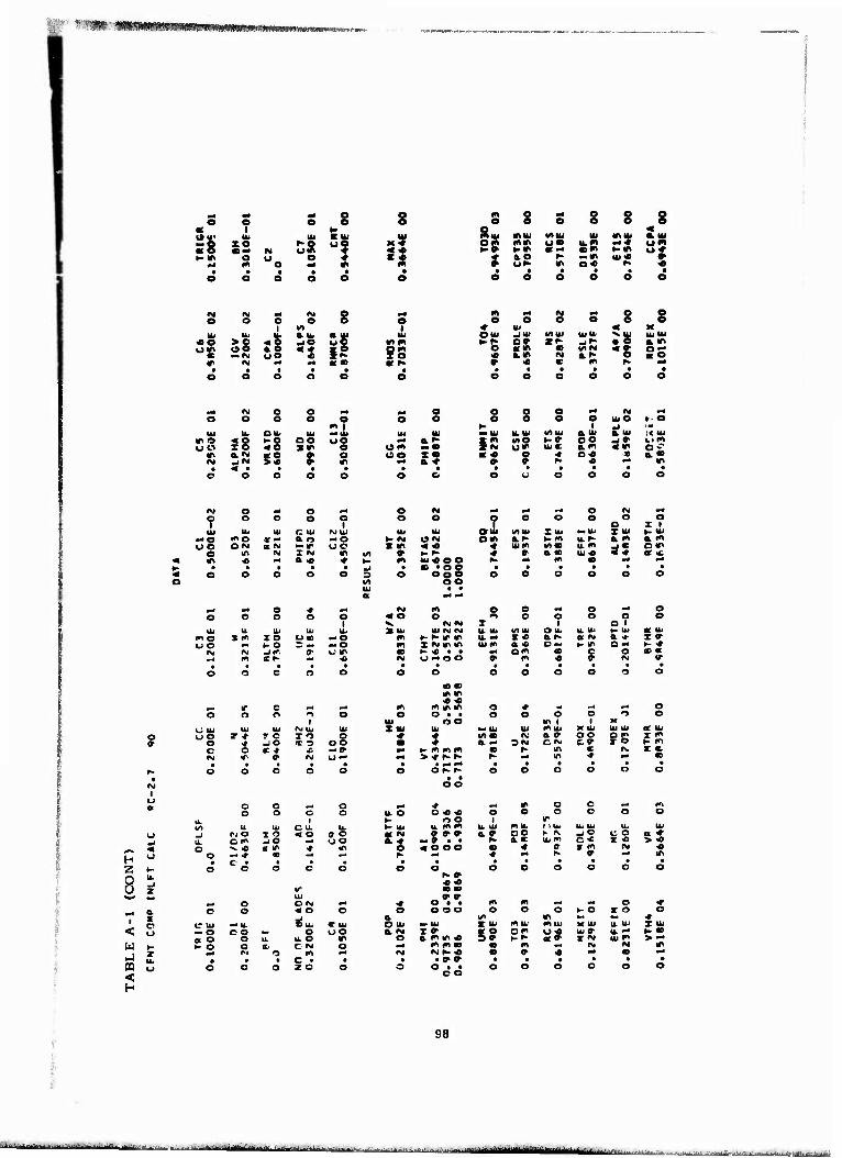
•Wm'&'m^Xt'mizmKmraiemmK*****
n e e e i »>
ze r>Q oe o u o ♦ •n o •< «t
I o s
a u, a tu «e >o <e JO uo uir oo a e «« i o
« —fu uO « 2^ w <M •• •< at •
s
e I
s s o s s s 8* MIU MU IU 2» im es mm UB u.m um
►.* «X am Km u« $
0.0 ^ ••ir ■u« V ur- IT o« ^ •c • # • • • •
o e O o o e
m *4 IM 0* o s e e e o e ♦ tu « K OUI *AUi lull. ;S IU IU h-^ Xf Jf a. m «w • W)(M -s OS ^ *.» N ar> «o
9 « C m ^ •4
KIO
«M e o v4 o o o O
m | u. ou. IU — IU
s§ I-O oe uo «o »m e ta 52 ? o
om »•• c2 i?
o e o m* N ^4 e o o O IU O ► o
H 1 •< Irt
M IU u.iu VIIU aui a iu 1« IU
JK MO H» oe _i0> Li m U* UIC a.m «m o c • « O ■» o« « a »
» »• K « in
8 ^ i < w pa <
#M a p^ e ** O H «« 44 f>4 o <M ^4
? o o o o e O ? o O o O
o o Z 1
IU IU IU C IU M UJ IU IU OUI WIIU ZIU MUI Z UI (. UI — O m e « •• a o -o h- «M ON OKI 0.»- *• m U. f- a m am OO OM KM — IT oe Kir «<o ♦ uim VIS u. m * • om
o IO IM X «J w VI » »- ^■ ♦ a a <D UI « ♦ * * « IT « •* «O ♦ H- m iu« ee K 44 m • «4 44 H • • • • • «i • -og§ • • • • • • < o a o o o 3 O o e O o o o o «1
IU a
oo • • •4 »4
prf mt o * ^ M m e o -* o -4 o o O o a o
1 « O o
IM IM X o o
1 o
o o
1 o
Oi u. Ui IU IU X IU IU IM IM U. IU VI IU OU. a iu ►• UJ ■ IU fn o »m zo uai -o m >- ^ rir U. »4 z« a r> a «M a * I» u o K O — o m X «M m in turn a « CM •- Wl O «4 t- •*
<VI (SI -IC. " a c in <e »- « • • om 00 e o at m Ml m «1- <fi M U-4 oo » m « 0- fM V
• • • • • • • • • • • • o o c o o O o
• • ir m « «
o o o o o o
^m if c ^4 «* l»l m m ir o ♦ 4 ■4 ■t o o o PI O o O
HI o • •
oo o o o
m I o
1 M o o
IJ ui IU UJ (M |U IU ZIU IU »IU UI miu K Ui IU IU at ui o uo 7 * r e TO 08 * J I« • IM a a oo o s I2 9 o 4 JO « o • a. — 3~ CM c» r ►- m
c o « * •e — ff »• K m m m • r- in c r\. z m. IN* If » M O "• P4 > * h-r- h- p4 m •» •4 to • * ■ • • • . .4 -• t • • • • •
r- o o o O o O ot^ r- o o o o o o • t • o o
o ^ o o _ o *4 * ^ IT o c — m o o o o u. e o « « o O o c o o
^ 1 ►- oo 1 in irt u IU c u. u. »- IU it m m U IU mu. 1 i u. lb Ui u. UJ
u «i ft o I o < o a o « «v -?'.». a. » oo ► n. ss c o ■ 1 _» u. O I" JO •JO 'S ^ a5 IU m X « > « < o V « ■ IT •* «i « o oo • « o- x m IM « o o — * a ^- •# nl K » M in
• c • • • • • • • • • • • • K o o o c o O o o O O o O o u. P-» J « « z V • «
IU » 7 Mi o O N « o • • m m ■4 -4 o ♦
a. e e « o o O o o o o O o K O I o o s
S Ui a w m *— ♦
c? C Ui ~* u. C IU O iu M> IU «r ui mu; mui M UI u 111 z ui (_) «O c o M* o UO a<M X» or e 5» om s* tu a u. •4 t- m
a O o u. u. O w e a m r. « K^ T<M ui m > -4 *• * O o a. C «M o •4 mm« • m IM IM m 7 Mt M o m <M IMf.« • a « M « M Ik • • • c • • • • » 0- ■ • • • • • o O o o z o o O O t • o O o O o o
eo
98
-■ : -lir .^■.. |
• iriiHnTtiü MMMli üMa : ^-a4^,.^.^A...l;l4-^i.«.,ii.i.v •^■.^^^.
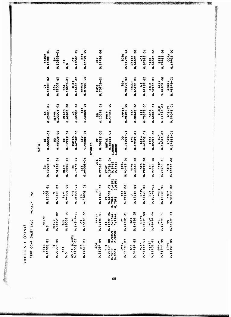
v'mspie^-vm wmmmmmmmmm^mvvmt^mmm'' ■ <mmx-Mm^m^^^s^^^^^w^w^^i^^0^^l!^>c^
u I zo
s
s s in Km
o ♦
IU
55 «IT.
e t
IT M
ss ?§
O e
* 9 * 9 «JO
o e e V) i fr Ul «IU IU wO UO «no -s 5? ?5 #* «• OC N
m e .4 o e o O e O e o S
O « s* IfMU </tiu IU tfl IU a tu mit. UN U.N •^ «« UN
►-O »-« «• c« ►- ♦ O» 1» a « ^■ -♦ iu -o » • u« *> o« ^ « • • • • t .
o e o o o o
m m rg 0* o •^ e e e o o o
♦ IU « » 1 O IU ^ IU tniu IUU. S.IU U. IU t-O am z • _<<«> • o a. «
M U M X v).* «r- e^ « am «« a. r» <D a V' » « • (0 • a
N o o N« ~* o o e o «i N o o o a
in 1 o o a o o o
i U.O
IU O IU UJ — IU IU IU M UJ U. IU (A IU a u a iu
8 »- o QO oo » a. « X IT no • »-N c* -i« mo ** 5 tflM •• i« ze o« IUM &o Sr- 5S 9 s Z ^■
a « "* § in o. 00 II
oo me ON
iu
a IM
o o OUI IM IU o. o -o »IT O O I «M m a.« *
•* «« o * -« e o o o o
1
IU IU IU lb u mo s « z c e r -o oo «M K O 3 (^ -o
<M -i m C cir m «r» '" «
o IM p4 pi m o N *-» o a O e O o O
O X lb
o Z 1 t- IU IU IU OIU M IU ZIU M UJ
¥- — u« 08 a t- 1- o u. — a • a. m x <M « m IU m M0 u. ff -im C CD
c ►• m <0 » a M Ul IT « * Of * m ui«o e f- «4 * «0 —t • • «oo • . • • • • o ooo
ee ~4 ~i
o O c o o o
IM m o o o o •H o «O o rt e o o o o V «M <M z C 1 X IU IU « « u. u. 1/» IU OIU lb lb h- lb a u.
•0 »- ir ♦ ♦ Ik •■ I « et» a -c a ir X r- IT Z r- m tf> IU » a « ot> t- 9 Cf t- m r» H tf\ • . 1 c m o C o c <r (M u ^e e m M 0« IM o
»»
?
t u
— IT o ^ -- o a o o o
U lb IU lb fM lb lb u o TO x e I o o
e 4 w C c o o o o o C « •o -a IM ir » M ■ i m*
H z 8
< w -I
<
& x c u
c o •1 o o o o o
lb 1 1« lb lb C lb lb «J N O z o <c o-o IU om JO •-" UO c v « tC IT .» 10
o — ■♦ a ■^ • c • « • o o o o o
o c pg —' o o < o o
o iu — lb CD lb ac ib
:§ oo mm e oo e lb u O w
>- o o » OM o «. ■M o m • • • o • • o O o z o o
m m « « o ♦ ml — O o • . o o o c
lb o e IT 1 1 Z IU UJ 1 UJ Ib W lb X UJ
N in i« * a o o « CO o . a i-i = «M o« oo M« k- N m m K f- N o t
>Mi • • • • o Of»»
• • o o
o o O o
B- «**
^ in O c lb O o o O c fc- ♦ ♦ 1 ir t- IU ib m m u. Ib I" UJ i». Ib ib Ib a • Of» & < c lt\ ►- r- jr. a — •- o • • (M a r- lb a c ♦
o « » oo K ■r • x r f- «4 4 K » c? •
* IT ■> 00 IT »
• O o
• O
• o
•«• O • • * m mt o OOO c o o 1- o
a i/i ir ■■ O lb *- Ib r Ib ^ u c IX' V UJ a, IM z ■o a fl c wd u IT ijO
o a <" - 5 IT ►- K a JD i m .M rg i^ o- a m* IM fM IMP- * <r C ■c • • a o> • • • • o o • •
o o o o o O
lb (U CO I o
o T O
U. K
«0
o
c o
a iu
z o «r
> o «
■r o •*
T u. >- » > — IT
99
■ ■ rntttammmt ■i^^MIH^M ^■uriiu. ., i,t..i i nrn n ii if iiiriiii'ikri ■>

SS KM»
ze o
lit
I ur i e o «•
e e
uo
o o
«10
o oe
e e m in r* a M> o «
e
o
o e Ui mm
o e
•o
IO
>o oe
-* IM o ■4 e i
e in
o o 1
tu a ui a U; Ui « 9 a.e it ¥S Sie
to oo « *r- m* ** «• ■ K
„( »i o o m*
o o o o o m I
UI UI OUI Ui -> UI IT O «o KO CO uo uo IO «o «IP o
1» acsi «o o- o fM JM >« a lf>
oo
o o
a 9 — o X *-
e o e o e o ♦ UI « » 1 GUI ^ UI <AUI ui Ui VUI u. UI h-« e» *i J» • « a.«
IM U <M f in-< «« 0«B « o.ir o a. r> » a * o- « • m K 9 • • • • • • o e o o O O
o o o <M m*
o o o o i
UJ O -1 -0
>.ui U. Ui l/l Ik a ui a a. k Ul
IS !/>.< ►-Ifl o W J* Ui O uf- UI M & * <w o- « « O 1A O «0 K a.o
» » ^• « •>J in
IM o «^ o x o «M w* «4 X o IM ,- O o o o ? o o o
1 o o o
o0 o I 1
UI UI Ul oui CM Ul Ul Ul OUI in ui Z Ul Mi Ul Z Ul >- U.' — o mo a -• a e -o 1- IM Of- C CD O. K K m u m a. o a » uo OM « M «. IT. u o z o < * r- ui m <n m U. <D _i m o in
o 1A IM IN Ifl </l 0) *- OD • o> o. IM ui m < -t a •* « m ■e •4 a« * 1- m Ul « o o K ♦ • ►- • • • • • ^ • «t • en • • • • • •
o o O o o s o 0S§ • • o o o o o o
J a *-l «4
— m o i _ N m o o o o p4 o o O o o «o e o o o r> O o
r V •«■ ■» z C 1 u> Ul Ul Ul Ul XU. u. tr vv u ui in ui OIL u. u. t- u ss in o I m TO o« m O IT »- r-* ♦ u ■* r « a « or in 0. —
U O w§ »-o * X — O * I « IP IT Ui c a« CiK ►- o C 0 t- fn IM -1 m 9 (_• IP ^- ^- in • • o O 1" IM ~t O a- ec
m C f- ** rw u — o o 9 m (M e- IM 0 • • • • • • • • • ■ • O O o o o o o
ÄS
o o o o c Ö
m^ \t\ o Fl x n* m « < o * M x •* o o o o o
1 o o
U: o • •
o o o o O
m i 1 o o
U u. 111 Ul IM Ul u> Z. OJ u. M UJ Ul m u K U; U U a m o uo 7 x I o TO o f -t U) c a * c •* c o I <r a o * -1 o S C O 3 a oc a. — 3 CM OK". C !>. T O t- *
o C « * -I — 0 «4 ►- — a « 00 K IM O rw a a IM ir ff IN C -' ■M > * — - f- a« IT IT ■M r» • • • • • o o • • • • •
r- o o o O o o O f ^ o o C o o o
H i-
Z Ul
3 -1
a z u
< u
M r , i UJ
aa <
o o M o o c c c
u 1 tr u< u. C a. u -i rvr> I o < o 9 e UJ C I* —* c -H u o O x « « «■ ■* m
o -< * ec ■N
C • • « • o o o O
u.
o
X o C M «M
o o < O -1
o c u. — Ul n UJ AT Ui — o CO ■M o u o «o o u. u o IT ►- o o 01 ON O
IM o m ^ c • 20
m4 * ** m o c *l (^ U. C o o o o o o c o o K IT If I IT 1- Ui u m m u. u. r> Ul 1" UJ U ul UJ L or N -»a a ^. c- ■0 h- V -1 -* ci r a r; e N — o • • o a K- Ui e c * r IT > o
O « -• o o ^ ♦ a. I m IM ■e K Mi -»• t*- c ■rf IT • • • • • o o
f IS m ir 00 OD
o o o o C -3
■» o • • 1«^ m o •f o e o o o o c 1- o » o o
a. i^ in M MM ■»
C Ul *» U' z a. m $ i« UJ X u. u. u- T ui a IM I * 5 m O u« Ul o u.p K O
o a if ^ IM ir ►- CD a <0 I " UjK > IM IM w » or m ^i IM in
IM *S' K ^J a 9 * •4 O" • • 9 9 • • • • • • 3 o • •
o o o O o o o o
100
—"^ ■—"■•——— . ,■! | ^.J—-. ...... . . -^ mmlmtt ■•iVriiJH; -^-.-.^-.-..»--— -^-i-..^

'ÄfcVH^^wfwsw»-- ■n*». - «n. ;>iw*-" t&' *.-***imm»&r*'i$m' '**'- '
• t «Atti lil
Hm e u e e
e i
s ^§
2 «
S S
8 S § § 8 Q « mui «>.'i VIUI
Zm miu s» om «»* um ^ •*
*■ ml KH «« HM UH «4 ü.* e SS tu« N 0> O^ prf H « • • • e o o o o e
an a. Ib u. tu tu a. tu ai tu
«o >e «S _to u5 um «»e a o «♦ xö • «-«v ue « xf» S2
o o o
o o
tu tu o tu tu me «o HO oo wo io «e xm
m o. IM so o> N -j <v >« c
o «n I •« tu us s
— e o o tu tu « «.H
OM —• OO X « — ft. # • •
e e
e e ö o o ö « tu « M OtU JlU V) tu tu tu vtu tu tu H« SS ZN j -< • H 0.H
N MO «H OH N a.H pH «L* KO » m ^ «« ■4 PH • t • • O o o o o e
O o W« «i M pH
o o o o tue HO 1- niU tL tu M tL atL S-ui «M trtin t> m or- _lO SP Z« U«M tue 0.» «» « •" e m o» • a pH » » IM m «« m
<M o PH o PH s N ^ PH „p o (M pH
o "3 o e O O o O o o o o 1 1 o X 1
tu tu tu o tu IM Ul tu tu oui muj X ui »tu I UJ HUI -HO <no «PH & o u8 »-r am OIM a H H H IL * am an uS C<M BIM »-m xo «m Ht tum «/im u.m
Sf m oo
O m <M X«« m tn « H« pH o- a o Ul« CH < m « PH a « ♦ H in ui«o e H PH m • pH pff
H • • • • • «1 • • »o e • • ff • t • « O o o o o o om s o O o o O e O M
tu • • o
• e
M« — o * p- IM in o O s o pH 8 O o o o a «o o o O o o i V ♦ ♦ X O 1
tu tu tu tu tu XtU tUO ? U. Ul t/t tu Oui U. Ul H Ul f3 f O » -H z o c s •HO » HO« u. » X« A « a m a <r UO • K O 3 PH — o n X»m «r tu« ?s om H « oo HH
M R Jf« » um i H« ff t « s « mm PH ar- PH « •M U PH O o » m » • • •_ ff • i • ff • • • ff ff ff o o o* o o o o o o o
t o o o
i m4
i PH m o «■* PH m mH H o ♦ •H pH ■p o e o o c
1 n O
tu O ff
e •
e o o O
m i O
1 o o
o tu tu u. cv tu tu x tu Ul ** UJ UJ in Ul K UJ UJ tu K Ul « oo Zir xo X o og » H 1« ♦ =J a m om O " X« tr e pH .JO »o H H a * C H o « K < PlM
o • "t •o -» O H» m m s « « o »J M •* M 0"H -ff xnm • H PH m IP mt • • • ff ff ff • in m • • ff • ff « r- o o o e e e OH H O O o o -p» o •
1 U
• o d
a o O «P o PH # pH m o o a^ m o o o o tUO o» 0« o o o o O o
u. 1 H m m ) tr trt ~« tu c tu tu HUI um m u. tu mtu m tu tu UJ tu Ul
o -1 z o < o »o er H «M» » a » C» H « -1* ¥S «m -> tu e m -1 o PH oo a K -e • • H a» Ul ■» OH >H « o ^5 «m ■♦ m pH « PH o o <a IM » xo IM IM ^^ <j o c PH pH « pH * pH ^. • «ff m H • c • ff ff ff ff • • • ff • • ff Z K o o o o O o o o o o o O o
tu ■e « P -1 m o- o z «n ■> m >^ tu » • m « pH o CIM «4 ♦ Off« • « m m pH PH O «
a o o « O o o oo« o» o o o (- o X o o ^H X pj a i/i m
{tu 1 U o tu ■H tU «I tu • tu O UJ p- tu tu tu X UJ m uj m u- K UJ X UJ < U -o CO pp o <J2 a rt tm M w oc« es u» U19 U. -H H « cco o tL u. o tr o ft ■* m c • c
O X 3 «0 a « xo UJH > ♦
W H *- o o a C <M o pH mir i <♦ o ♦ IM IM * Z PH rx o 1** PH IM N H U H u m » u> «H IT
i-l tu • • • r • • ff ff a » ff • « • ff ff n <
u o o o z o o O Off« ff« o o o O o o o • o « • •
H
101
MMU^MMMMIMM - ■ -■— «■■ ■! ■ 11 I p^M^ff,^! *-■ ■ '

^^^MWiwtfrMMtHWv^wiciirtMwnrTta.w,-^^^^
e o o « t
:S lit
xo -! ««M M ü8 KIT o U ** <n e *l . . • o o o o
IM M «4 <M o O O O
l/l u. lb iL a.iu «o
uir 5§ a o *i • — IM u e «
s s
s
3?
§2
e o
o
IO o
O u
S S s s
IM
a. m
c m •t >-i a. •
W>U1
1/1 UJ
IT
ui miu u.« "If. «o t-O — ir iu<e
e o IU UJ V Ui Jg • t uia «*• a ■» N
o
o o
K lUUI a. M os
*4 IM o O «4 J o o o o *. IM Hri
o o o O o m 1
o o o o o o 1
UJ O KO
UI lb O UJ UJ »UJ tit UJ — u. U. UJ muj a UJ a UJ K UJ ino « o t-e oo ue m 0. * I "• mm •-»• c» j« UJ — <JO IO « o xir o WIM -o zr- o m UJ c a o «f- CO
in a IM ae o ? s CO z « « -< o » oo Of aiM M JIM > <e M a. * a » « •c ». m • 4 • . • • • • • • • • • * o O o o o o o o o o o O O
»\i O -^ o — o IM *4 ft 00 o nj -. ? o o o o o O o o o o o o
NUJ 1 o X 1
w u> UJ c ui UJ UJ O UJ in UJ XUJ M UJ ZUJ 1- UJ — O m o or — a o MO ►-» Oo oo- a ^• k- •" U.M a « a o uo O R' « IM •-IT uo & * «5 IB. UJ m m^ U IM -JK c.«
o IT IM I IM IT in IT H- <B fo & & — Ui« «♦ or « < If! « mt a« ■» ►- m UI « » C r* m ■ ►- • • . • y • CD • « « . . • • . • « o o
o c o o 3 in UJ s
o «ff . «
oo
o o o c o o
■. — o * ■rt M m § o o o .4 o a o o o e 4 o o o o o O o i V in m X O 1
UJ UJ UJ UJ UJ »UJ u. <e « IL UJ in UJ OU. U UJ 1- UJ a ui WO xo> z o c r -o (M »-«mm U. « X « a m or in a » I- DC m ►• a 5 w -o 9 I « m in UI « a * r — •- e om t- h-
IM a -j in » OIT K t- ♦ . • •-• c m M o ■c cc M fM <0 K M « o •- o o c m P4 o V . • . • • . • • • • • 1 o o O o o o o
* ♦ i*i m o o
o o 1
n o o
-- IT O _4 ■tf w m c • o * .. Ml «^ o e O o o
1 a o
UJ o • .
o o o o
m l o
1 o o
U UJ U< UJ M UJ UI X Ui III — UJ UJ m L. X UJ U. UI a u' •c u o r - r o T O 08 IM m in (M ■e a IM 1 o c. P 1 f a f? M -J o ® o ■ wi a * 3 * c " -4 X « i- N
o at x <r •t -c o ►- o- -. — w * IT INj ■M I m f^1 ^ a A; o" > l- o o K IT IT -^ cr • • • • • mm • ■ • • .
►■ o c o o o o o •- r- O o O O o o <M o o U a c r? ^- o — * ^4 in o O n. i* ^ o o UJ O o * * o o c o o o
u. 1 K »- h- 1 ir *r u. UJ C Ik UJ *" UJ u <*> m a. u. Ci 'Jj m UJ a ui UJ u.
o _j rv C I <■) «« o »o or if m » » a r» c * %~ r -J * Off a m —i UJ e i" _l o oo a. a — o » • V a o u. -- Of X o > ♦ < c v < c ir ^ rt « — o o *■ m B1 T O IM IM
^H, *-i c -• -f m ~4 « «4 •t *. ^. v *. m H • c • a • . • • • • • t •
N- o c o o o o o o o o o c o u •C If o -1 f- to n 2 1^ c CD c U 0- 0" ^,,' PHJ o CJ M M * o • • i^ m -* M. o ■»
P o o « o O o o o o c o o K O x o o t-« X J a m o M« * i 1. IT u. -i UJ <C OJ CUJ C UJ *- U' « UJ 1». UJ m UJ M UJ U Ui Z UI
< o — o c o k. O oo a. i« I ♦ «" CM o » UJO u« I-» a o o U u. O m o o. o K- r- 3 0- 1- IM or « I - ui m >•♦
w K 1- o o c C M o «• rg in O •r o ■# N IM •♦ Z M* IM o m 0* IM IM f- K or <r m J r «4
J u • • • O • • • • <r » • . • • • • m u ^ o -3 z o o O o • • o o o o o o
o o < H
102
-■— - ■ ■ ■■■■- ^ - ■-'■■-■ ■ ■ ■ -■- MJMi n [| |-1 | -'^ ^■"*"^^----

HMm ■ S-**«S)*«^w^- 'fi^^issr«?» v;5«»^iSKa5*ffi:''-a^*,*'?s;- • *~
= 8
^t «4 O o o
1 e e e>
Ul r**
» Ul IL xo UO )»» em M u ♦ ♦ <«
o U o ♦ SN w o •4 IT m
Ul we
o i
lb — O oo
o IT
m e u o
>o
111
xe a «M _i~
o o
m o O ^
o i
i_ e
o o
Out I- o « o
S3 o
o
T O ►- C
l/l a ui
<1
o o
Ul o o »IT
c
O ui a o M n T "M a -o
o o
•-'S S S
«i i
o in
INI Ul — o u o
in •»
o I
Ui
C ir Z x
in o Nl o o O o o O o e o
a < mm tfMU M U. Ul mm a ui o in mm u w u « — M u» ►- m t- in a ♦ « « *- ^ O" »* a (v » — m III <0 •
e Of ♦ o« K « • # • • • o o o a O o
m IM w* o o e o o o o
■♦ in « K OU, -IUJ VI Hi Ul 111 VU< u. u. t- ^- o^ Z m -i m • « o. m ♦ «» V irtC) «E* ON «M ar- v« a « f- a o c m • m «ri ^
in O m Oo
o o
Ul a e — m Xm a. •»
o o o Mri (\j ma o o o o UiO I-O
1- 1 _ u IL Ul VI 111 a ui a u. K U. »«M i/iin ►- -* C '3 _i« u. -< IO um Ul IM a. IM «f oo Of — o I" oo c a M » o- <e "* in
o
— n-
o r
o i
— o — o u m
■a
o (M X «• x o IM m*
o o o 1
o o o O D
O T 1
a< Ul Oui UlUl X Ul ul X ui h- U •- « oo e m a r- ►- m u in a. x a "< S IM « x ■o uim V1K X m4 jr- o —
in ►- » m » a <M U « <■* a « in UI«C« i* in ec mt x • « .a » • • • • • • o 0??
• • oo
o o o o o o
IM c c o „ n — o < o o o o o ^ o o ^ m m x I C 1 Xui ui in m u Ul o^ U o in u u K U or UJ
K »-«mm u fSJ I « a m or in a o I * r- x m m m Ul * a « o — K O e * 1- * ir ►- ♦ • • •>4 D m « « r «■ IM u-o o o- in « & <t
_« <n r M •* o o o CI o
o ui Ul Ul f*. u- u o o r^- r o r e" o
o •^ -i c a 'J o o o m a. •# ■o — o M ■* » o —
I u
Z
8- a
o
< U J
<
o o p4 o o o CJ o
u 1 »o Ul C u u -1 IM m T O « e »o Ul om — c ■M u o o V « «■ in •r m
o - ■♦ « Ml
c • • • • o o o o
Ul
o
■4 o O IM O o « O
mi o
om x u. eo U. er ui "O o o mm o u o «co o u u. o in ►- o o <c OM o
o • 2 O
IM IM ^n m c « o •# mi mm M o O o • • c o C n c c
UJ o o IT 1 1 v- III' Ul Ul u- in UJ M UJ u u a UJ
o eo l/- IM ■r a —< c ♦ c a- I *' cc « a •r 3 -» c ■c c- •» I ir i- i- o N- «ff- et * •» ni «■ 1 <M
> met • p- in ir -m o- • • <M IM • • • • • O or- r- • •
o o
o o o o o O
. •# 1— IT o o -- m u. o o C 00 o O o o o c 1- h- f- 1 m i- u ui m m u Ul i^ u in u. 11 UJ u< u rf m m ff » o fM c Ml K ^ _l 1»- oer or x a. er •M o • • p- a o Ui mm o * z o > m
mt « - oo m m o- r c M M ■e >r m* *m o mm IT • • • • • a o
— m r~ w a, ec V IT
o o o o o C
■* c • • i^ c mm Ml o ^ o o o o o o O ^. o T o o \ u- (T *
OU •M u I U' i^ u 1^ Ui *c u- a u. T 'XI 0. m T IV a. o o K O mm U. e u. ec, (- •
o a & fr *. 1* »- mm a m > mm u. IM > * ^ — IT 'S * c ■t r^ IM ♦ IM pg p- ^- ec o- m ■M or Ml • • » » • • • • • • O O • •
o c c o o o o O
103
•- -..--..-^^■^-^««-«^-i-^-j.—-..J.- --■■-imnun MMM --■ - i ■,.... . ■ - .^- . .,

■ri ft ^ o e e o o
m. i H
\l m Ul KUl 1% IM
NO" UO * WS e U ♦
•n e ^ * • • • • • o e o o o
N <M m* IM § e e O o 1 tfl
u. IU 0. Ui a u. «e ss * 9 JO oO ow «•» «? • — fvj o o « z^
IT M OTl M« «•
< e X IM
in
O I
UJ
o-e X - at r-
m e p4 O o s o o o o o o < «to. s* Vim UJ ITUJ aui oo- uv> u.« ••in bJ »-» »» r- «f 1« a» H-M •ri a.« p< •••»• UJ «0 « » u« IT o« !>. « • • • • ■ •
o o o o O o
m m* «M o M
o e o o o O ■♦ Ui « »" 1 OUi -1 Ul </> UI U. UJ V u. Ul u. H m o — ztr J — • * a «
h- K •< ir M — **■ c« N ft.« a a * » a ir » ir h- m f- »
— O o o a _ IM M«
o e o o o o 1
u.o t- o
LU Ul x U. U. UJ mui a. a; a. u X Ul * a • r >M i«0> t-o Clf> _i» UJ «0 O rg »K z>- u* Ul V a o <(r c«> C O z « K -* o <» Ox c O. M
a-» c 9 K ■e «• IT
•tf (M O O M e o o o o m i UJ U; o Ul Ul X UJ
WO «O >-O OO OO uo zo < o sir o
in a IM a o » o IN .jlNJ > * 9 IT
ry O x o -J OIM x-^xo^-* ooooo OS ooooco t I I Oil
UJ UJ UJ o uj rg uj ui UJ o UJ «/) UJ Z UJ — UJ X UI K UJ ■«o "O «x ao xo ►--' C9> CK o.h- ►-« UCM a. ■o a« uo o IN oc IM »ir uo Sir «irt rs. UJI* »/^ -* ucc «jm cir
o m IM i ^J iriin ^ i- o* 'O 9>a«oujin<^a<# « tf> ^ •- & .O * K- mui^ioo h- X m CD x x ^» • • i • •_; « ffi t o O • * • * * • «eooooSo ooo o o o o o o C */) c o
u. • • or " •*
** m O + " (Mir o o o o -• o o o o o o «oo ooooor
IV « « X C I u< Ui u< u. ui Xu. ujoou.uj«ouiOu.u.UiKUjau
me so zo am — o — »-«irir um T * a« orir o. or i IM wo ^ ^ o ?x xo m ZiMirir u. — a<c o *t ^-m cc f-ir
IM « -j i^ OUT irH^** xcir O x •ca^at x (Mior- x ^ rvicxoo c w x a- — c
ft« IT o «I x O J^ o o n
u u. I4J UJ ro u. UJ * o o r ■» I- o I o O ■ o ^ -i o ir o c o
o o s. * -t -• c ^ * o- rj c •*
^ ir ^ AD ec o * MI _• x ti • • c u o O o
o o in 1 t K Ui X UJ Ul m UJ K U; Ul Ui K </> o- K a * o o c t* O 6. tn = -t C fM t c 1 ir
i- a. fM IM m <C (^ > m oc cr ^ IT IT —'
H
8
Ü z S ^ < u
H
c o X o ^ -» .* ir o c ftM j^
c o o ^ L o c o- a o o o o o o u. 1 »- a » i IT (^ u. U' C u. u. V u- u m m u u. tr\ UJ f u. u. u a' ^ fv o T o < o a o » •f (^ a ff a r ■c K -- -J 1- c r or a UJ c f^ .J o o r> a o ft« O • • f^ a o u-o r -c T > 0- c V •c IX IT -f ir r^ < ■H o o ■» m a I c r.
o v< -t «■ —' *-< 4 —^ ^ **» K 0 ** If • c « • • o o o
u
o n o c o o c f-i o
— o C (M WM ■» o • • r^ ri- v ft^ O ^ f o « o o
o. o o a O
ul o o o
IT ►- o S^ o
•«■ ■ ft [J ~* u< cc u- <r u. C UJ — u- T UJ c UJ m ui X 11. u u. I u — o c o ■H o LJ o a * I -» or IM 2 a o •» UJ x u a H- fSJ a O o u. u. o IT o a -» m eo O t- m or — T - u. ac > tr K O e or C IM O X —1 IT O IT O ir fM •-i *
M o 1*1 ■rt fM IM f* ^ X cr IT *M a: m* • • • c • • • ■ o- a ft ft ft ft • ■ O o 1 I o o n o
o o r> o O o o 3
104
^«M«. ■ ,■ — -, , iiiiiiüimili n iMinr -^,__ __ _ _

'ym*
o a
S8
o I
111
£3 o
e o
e o
o O«
m e
e e
o o
tnui </tiu Kin S«> am e OK —
mui aui "•1 w» H* «jo
IM M p4 «M e O C O O
m S
Ul UJ Ui a iu ■CUi «o > o « o .lO oo oir oo a o « * ss an »ISI u t^ «
IT M •^ « •
o I
m ~t i« *rt «4 o o O o o O o
<♦ Ul « K Cu< «rt u. 111 IU VIU lUlf »-■» QM zt* =(S • o ?i8 m K* w <« ^- a.» o a» p« «N • ♦ t- M «4
•-I M o o p« t* o o o HI p4
O o o o o « 1
e o o o o 1
o l
IU Ui O iju Ul CSÜ Ul Ul M Ul U. Ul </> Ul a. ui ino <o *- O oo a 0. « X * no» t- B O 1*1 oo z o « o sir e 15- — r> zo oo Ul o a.»
IT a «M ?s g. o OO I — ac in o » o-« IM jm » W\ pri a.« c » m in
UJO I- O -I "> a. ui K ui _i« Ul" «a O«
<B aN
O I
U! — o oo
o
u. i»> o o o
CM
o o
m o O rg ac IM
o o
T O ►- e
o
O
a a; a o "- IT I «M a o
o
o a-
o (MUI — o oo
in
o
o I
Ul — o oir
■c
o IM <— M m o o o o o O o
Ui Ul 1
Q Ul «nui Z u. •M Ul t- N o* c m & f- K -- u « X • < o • ui m 1« IM U.O
0- I- — o » a m Ul •o IM uif- e o t- fM • • c ..» ■» • • • • o om
» •
o
in
• o
o o o o
M in o o o o « O o o o o o V » e z xu. UiC a> U. ui 1/1 Ul O u. U. Ui
r- t- « o o U. O z <c a — «r o «M I m m in U. f- a -o c c ►- >c IM K IM • t «1 cr- o IM O-O o 0> f\ (*i ir
o o O X I Z Ul K Ul a. K a » J ■«■ o* «■» «em
— (M
- O o o
O I t- U. OL u. a IM x o c r- ►- m
— c«
■
OU. oo
o o
* o -I o a -»
i rM u. I O a o
e oo -0- O "t
8 c:?
1 a I
< c
w 1- ►J r PQ U'
1 . < H
o c pN o o o C o
u 1 tfl u Ul C Ul
v* MI IM O T o « e Ul Q 1" -I o «-« oo
■v « a m * ir " rt -. * • -- • Cs • • • •
o c o c
on u.
o
o C- fv- »- o o
Ml
o
O u -* Ul OD Ul OC Ul — o o o M e oo a o o u u o in I- o o ir O »M o
•M i« — ■P o ■t .rt P4 o o • • o o o o
U' — w* in 1 1 I Ul u Ul Ul m ui X Ul
in o t/i m o a » OIM in o a OC r m c r- O » m H l»i 0 » ot in » 41 » > m <r » N Ml •0 m • • •* <# • ■ • • o Of •
o
f- • o
o o o e
m4 •» — IT o o u, o O - m4 o O o o
1- Ul u. ■»■ i u 1
u. mu. IT m ui Ul Ul
of o- r- 9 9 a o C 00 ►- » _l« a M o • 9 f- a r- u.» oo < — o O "* o IW X <
- o o o
X Ui Ul tf Ul om z O 10- KM
o a »
o- at" i" >o — «
c • 2 O
• * • • a • * o ♦ • •• m m Ml «-I o *
o o • • o • o o o K O z o o a • m in 4 O ui ~ U' • Ui Ul Z Ul m ui 1« Ui >C Ul U. Ui ZW a m I 0- # * X $s cr- o * Ul — U. - Km
o a. ir i* c o c K -* a O z ■» ui •«• >* ~* (MT T cr T o- m m f* IM Kl <M — * o m o K 00 -t -4 00 •p • • o (t • • • • • • O o • • • •
c • o • • • O o o o o o
xo^
—HI nia^n^Ml^^M

ii o
e u um e
e e
<->c*
IT
111
in e mt o o s o o o e e a « mm «i in IA UJ IU «MU am Of i«» «J»M u. ■* ••K) um *■ m »-« •Cf- c« »-♦ u*
•0 & •« » — *> tu* <M • O»' m o« *■ «
* o UK*
m
o t
IU
u o
o a ui
S at IU
o i
Off
o o o o o 6 ♦ IU « K Clb -1 IU m lu IUIU V. IU IUIU K« O ff * m w* • IP o.<ri « er m ir VI« «■» o« r- a. to o o.ff «-
CD * • fa Ml M
_4 IV o o -• ^ o o o o ** IM ^ O O o o o
m I o e o O o o
1 IU O .1
KO
IU IU O lu Ui -<UJ IU IU M Ui u. IU «n lu a ui a u X UI iro < e ►- o o o uo ^• a M I « i/i « t- <0 OO Jt Ui V> uo z o « u •x *< a o- — o ZO u — lu « o-f «i- o"
IT a is of O I s oo x - a ir o 9> ON eo aiM IM -"•^ >« Ml a •» a: ff « If •-« <r
IM n <-4 o ** ? o o o o Ui Ui Ui C Ui IM IU
-O (*l 1^ or -< o o — o u o OM « IM — IP uo
o lt\ «M x *■■ IT ir < Nri a « ♦
«• «M o <r mt
o o o o O
Ui UI IU u. u. «< o Z IT I o c «> -o u e <c t- o ■* ■_• •NO
IM •♦ _i i" o UIP Ml l>J a- r- •0
O UI u c o
r o _> c IM U. T O « O
o oo -Iff
H
8- i
< w l-l
<
^ o »M o "S o o o u. 1 1/5 tu UI c U-' IU «J M O T a «* o ff n Ui C K" _J o UO o •v « to in -» IP <> — •» ac —»
a P • i a • o o o
Ui
l-t o
o O IM
1 o «i
o o I? UI -- U' t u. er ui -o c o w o oo a O o u. u. o tr *- o o s C INI o
o IM ^ — — o IM — o o o
1 o O o o o
O Z 1
IU IU OUi l/l Ui I Ui — IU Zui »- ui t- m o » Off a r- i- •M u ^- ft in h% * IM « m « ui m i/i< ut- JIM
ff ^ «i PI ff a « uiir « •» a IM IM ui K m in N — M <D IM • c • ff ff • • • t • ■ o 0$? • •
OO
o o O o o o
Kl m o o o o — o « o o o o -> o o o V f- f z C 1 aiu tu X 11. IS* IU O Ui U Ui >- Ui a u
.4 K U. CD > « a IM at — ft <c z • ff z —ip ip u, ir a ■c o n i-ff o a. K -• MM *■ l\i < 1 o m — — — CC » IM U -o o ? m IM » — ff • • • • • • o o c -5
1 o o o
IM m IM IM o ■t — — — o o O « • o o O c o o
Ui •^» .^ in 1 1 v Z IU Ul — Ui Ui (Ti Ui * IU UI lu a ui
IP i/> in o a •* oo OIM I ff IP * ft « ^ m C IM c m I a t- *
s K IM O O «■ ip OC tr o I * > IT. IMP) r- — ■T IT — ff • « * • • • • •
o or- i» r> c n O c n
_ <t ^ ir 3 o „J K". lu O ooo o o 1 o o O S- IT IP. i ir •- UI Ul » * U u rr> Ui m ui U Ui lu Ui « Ci !>. » O- ft u> r <« *~ o- -■£ u- or ir a. IM •» o • • a a r- w ^. c o T »" >^ « -oo o o 1* I c — IT
c O
c • z o
to CC ff ff
•r o • • o ooo
c C 01 — Ui ft. IP z m
o a 4i ■* « — » ip ff IM — « IP • • ff » O o • • o o
IS
ir — — O * o O I- o I O o IP * m u' in ui X Ul U Ul Z Ul
D m U ff IU IM U-ff I.IP » IM ac o Tt Ui o >♦
IP IP — IM m
106
■MMMähtM •'"'';'" "hilitilim

; :■ WWf«^ *?&*'' «WWWWW^ ;r' . ■ ■'^Mra^B^,J^;■';i■c>.--■.>l«1■.^■l^■"I^'
e « e i
Ul ze o o
o o
x «M o o o
1 o
UJ a< ttJ a u. «o >o « o -JO u«" CO 0. o « * • *• fvi oo 4
o o
oO
z t a a
s to s «
o I
a. 0 o 1 m
m o ** o o o o o o o o e
o « miu IT u> l/> Ui u* tr IU a u. o « m * u«o U. CM -* u« t- * ►-ir oca so t- « o~
•0 CL «0 — IT IU* m £ u« * o * f- « • • • « o o o o o o
m .^ N tm «1 o o O O o o o * Ul 4 »
o UJ ~l w i/t Ui U. Uy V u. Ui Ui ►- tr a n z — -i ■» • <" a»-
IT a m rg in c <l" co- f- a. CD t~ a a IT o c OD ♦ t- fM fl
w- Oi o o ^ «4 o o o o •-• IN. -M o o o o o
m I o o o o o o
1 Ui O -i
t> O
Ui Ui OU. Ui —. Ui Ui Ui — Ui U. Ui in lii a. ui a u- X u. IT o < O »- o oo e>o ^• a -o z r^ VI « i- « OO -iO Ui fl uo zo < o X « o o - •-1* z o O <M Ul» a -t < f- ce
ir 0.M a o » g oo TO a in o «M c m • o m M JIM ><o a a * ■ » r» in v •» • • • • • • • • • • o o o o o o o o o o O o c
IM o m* o -i O N ~4 •-i »4 o (M Mi
T o O o o 1
O o o 1
o o o o
o o Z 1
Ui Ui UJ o u fM Ui Ui Ui O Ui l/l Ui Z Ui UJ I Ul t- Ul — O mo a *ri a o w r> ►- O- o Oir a. r- t- f- u Ml Q. IM a o UO OIM a CM IT U o I N. < N o- UJ m m (* u If •J o oo
o IT INi I M IT ir «0 v- ■^ m »■ a te Ul If < ^ * — 4 m li, *- a -0 >t ^ IM Ulf. c o f- M ec IM H • • • * • _j • IS • mm • • • • « o e
o c o o u a
r> O IT tt
• • o o
o o O o o o
— ** o * i-« IM m o o — o _, o o o o o
I < O l-t
I o o o
1 f>
c c
1 r>
Ui u. u. U' u. 1 U. Ui -^ M u U- in Ui OU' u U' K u a u mo S er X O c e »M e ff 1- ■too u fN» a * a ir o o a m z - uo * K o z> M •M o IT I 9- IT U^ Ui * a. •c O V\ ►- <M o o >- <1
Sa •* _i m !>■ O IT ►- M • • c m <c f^ IM a « «4 IM 03 K M u - o o o m ir o- -- 0 • • • • • • • • • o o o O O
» 0
IM IM
o o o 1
o O i-i
IM If o v4 _* M m m m o -» Mi M« Ml n n o o o
1 o
UJ n o • • o o c
m I 1 X o i
UUi Ui Ui IM U. UJ I UJ Ui MM u Ui m ui K Ui u u> 0 Ui uo ? M X o T O o _ri OD mm o a m o r- c — I m *; a. -i o a o o n IT «D o a. * m o * c ■0 I a t- i»
3 •t n * <■ ff 1»» 1- — a « AC if ♦ o c I < 'S. ■* a IM c o- > !■, if * K •c If » • • • • mm • • • • o c o o n «1 o r- i^ o o o o e "i
I u
H < Z n 1-
ü ^* 7
.-' i a
< Z
w u
MJ 1-
ffl z UJ
o a Mi -3 o a o o
u. r UJ MO T O c ff "5 C m J O uO v i <c if ■^ if -i * «r o • • % •
o O o o
<
M« o o »^ Ml o o « o
Mi o
o iu *M U a UJ or UJ -o oo M> o u 1 KO o u ^ O if t- n o *■ C IM o
M o m Mi
• • • c • ■ o o o Z O o
^- ■* ^ ir o UJ O -i<f o o o o •- If If 1 IT t- a. u ■» ■» a u er- Ui Ki u. a •. K C a a ff o t^. »- ir a — M> O • • ru 0. h- UJ ^ »* < Mi O O o o K
*f Mi -t ■-4 ^ • • • • o e
(C (f c o O
■» o • • r^ ft ** o o c o O n c
a. IS »r« C u M u X OJ I*- Li.' r* ui a if I r. a <r C f«K U •-
r> c f^ -» u*. cr K (M & rs, ~4 e u- o- T If «- rg M ^ IT ts. (f J • • C O1 ■ • •
c o
cr » m
c J c a. u u c
tr if > *
I u > *
107
*M*im*m^m* U^tmtmmtm ^'- ■• - - -■ ■

— MM B- o o o c O o 5
m. 1 H O m Itl lu 1 £ lu •> O zo r- »\ uo K <M « o m* M om ♦ « m 1- »\ o U o * s «
^ o «4 s o e o o o o o
o m mui «1 UJ i/i lu U* irui a. ib cm in n UN u.m *4 art um K IP >- m «<M »■«■ ►" « o«n « o. « IM — ♦ III« HI • o <c ♦ c.« f «
4) o
fw mt IM o M
O o 1
o IT
o o 1
u. u» a. u. a u tit > o < o _iO uO 1/1 -M t; o o. o «♦ zo c - — iv u o <c ZN I m ^- W4 «« tC K
m «4 IM m4 a o o o o o o o >» UJ < K
C u- -1 Ib l/l Ui Ib Ib VUl Ib Ik •- <e Q l«l z -r _l w> • r- a r-
•o OC 1« m i/i« «» o« r- a <c « a» e «a flC •r K IM m «i
p.« IV O r> M
Cl O o o o m I
IJ Ib c u. UJ — lb IT O < O K O DO OO O Cl I O « O JIT o
u a IM a o o rv -J IM > « o- IT
« o —
o o
I» a in
a IP
o o
Ib lb I« •» u in
o c
Ib IM
o I
a ib c o a •* o <r
IT
IM lb O
a, HI
IM c — o — O IM «^ M MI o IM ■M
C 1
o o o c o O o i
o o o o o
o X 1
U- u- U. C lb IM b Ib lb OH' wn Ui X lb X Ib Z Ib 1- Ui — o m o a -- a n -^ o t- »■ O CO OO a i^ t- IT u. r- a m a IM o O n »M or rv ~~ tr o o I ffl < <r fl tb m 1/1 IM u IM -IK c o
o IT r T rg IP iy. OO i- >• IT, <r a o ib ir < m a o tr « «^ a * ■r K IM lb K O O 1- m w m IM » • • • « • A « • • • • • o c c o o 5 o o o- O' '- o o o O o */. a »
^ •rf o ^ «4
o c c o o
u. UJ u u Ib » o 3 1» I o r o- — O w o K C ^ —^ -o
»M >1 -J I11 o- U IT M a. r* «
in « o «N o M o O o o o o o o
o. » I 1 c 1 Ib f* K u- u w Ib Oib lb lb t- IL a ib
i- öD o- <r a ir a •c o. ^ a i^ a «D I - XN < ■» ib r^ Of ■c om i- ■r a i- » ^ — • • c -o ■0 M A' er- c — o o C m IM «• •M » • • • • •
o o n o O o o -, ^ o o o- a
*•• m w o ^^ o o . . c rt c o o o
o u a- u ^, li lb o o o <' ^ » o I o o <r o a _ c I c OO
c *> a ■* < M » •M » o- ^M <_> — • •
K C o c C o
►- — o o > m e o
• ^ Hi O ^ K
• t o o
IP 1
a IT C >n
o — o
lb Ib OO I 0
O
or ui X IP
I n. oe
Z
o ** _, o ^4 ■» M IT c o — m o o C o Ib o or- "
■e ■e c
1 o o
IP O o o
u u e u. Ib t- Ib u. * * rr UJ 1" u. tb Ik- u lb f, n r o « O er o or o K p c a m C <r ^ a JIM c o e " -1 c MI u o 0 IM v p • • r* a i- lb IP o» Z K- > «M <» c a- IT » IT *• <1 — o o a o P- I IP IP -• -t a- — »T -4 r* — ^- O) -4 •»
' ^ o C IM -4
a c o < c C <. z u' c: u. — u m x a ib
>bj c. — o c o M o l_ o a O o Ib w o If
►- 1- o r> c ~ iv1 o ? p.- c (*>
< lb • • • c • • l_ u c £ O o
c- • • i^ << ^ Ml o ■»
I o o c o o >- o I o o i/i IP >»
— li r ib ir a (r UJ x u lb li. I Ib 1 IP a — c_ •» U 1- ÜJ * ib m 1- f- a c * ^ = c i- m O IN. X * lb IT > •»
u IT a » ip IP m -« .r ip K <B * «M cc • a- a • • • t ■
108

'..■■aWft' itmnmrn» ■w———W "
OT •* Ml e s e e o o Sui IK Ul IU :s xe K* UO m N
• ♦ IM U(" * « ►- f-m e U o ♦ X IT •* m o IA N • • • • • •
o o u o O o
o o o e
ON
•e n a. m
>/>it>
o o
►- IT Ui «
o o < a. ui
I»I «
<M IM ^- 1M o -- o O O o
l/l o o
i u. Ui UI a u. a iu u-
«o >o < s -iO uO »r ir L)*> ISO & 5 <•* so O IM
•0 -IM u o * Z" I l« If IM — a « a h-
m ■« N .* o a o o O O o o * Ul « X
O UJ .1 UI MU. Ik Ul >. Ui tu U. ►- « o « r" jIM • -• a in ^• «IM «)• « « QW
r- 0. • IT a c « aO «i ■♦ f- IM ^ w«
— IM o o — MM o o o o Hrf IM ari O o o o o
m i O o o o o O Ul O 1- O
UI UI O Ul Ul «4 ai Ui u. — Ul U Ul VIU. a ui O. Ul M Ul mo <o »- o oo UO IT a - X» i/i « ►- • c * _iir Ul <0 oo zo « c »IT O c — — 0- zo u ■» Ul IM a. — < ir C IM
IT a. IM 58 • O CO z • ot in ? m cir o. a w IM _|IM o- IT a. w B r- IT »^ ■« ■ « • • • • • • • • • • •
O o o o O o o o o o O c o
IM o «M o M O (M ^ .« — o IM Mi
O o o o o 1
o o c I
o o o o
O o I 1
Ul Ul Ul o Ul IM u Ui UJ o UJ *r UJ XU. to- Ui x U. t- ui -O WO Ot ■M a. c o K •r o aw c» a r- ►- m u •f a •» a m UO C M X IM •— IT u o v i^ « « w ui m 1^ K u (T —J IT C 1-
9 IT IV T IM in l/l i^ 1- IM K » a. ■4 Ul* « IT or Oi « ■rt a ■e J — IM Ui ^ o o K — 1« CO art • • • • -J • c • on • • • • • • o C o o o
Ui a
o oo e o o • •
O o o o C o
_ — o •» — IM 1*1 O o o n — o o o o o o
1 < o o —• — I
o o o o c
o 1
o Ui Ui Ui U' u 2 u u. m in u u v^ Ui o u u Ui k- u. a u
i*o s^- X o o» o ^ ^■ — »a u <£ T ■e a O1 1» o- a IVI I tr UO « H- o 2 ma mK c <c I If * * UJ O a •0 C» ^- ^ i- * i- i-
IM 1^ -1 m o I- IT o »- -- • I ** O IT IM IV fv r f- •« IM c 1- — 4. IM u — o o c- m ~t 0- — tr • • • • • • • • • n o o r> O o o
IT if in if If If
o o c r? o
** ir o IN 1" * * o ^ o o 53 o o
i n
u. o o • . o o
if c
1 x <r n
U Ul Ul Ui IM u I Ui Ul Ui u m UJ Ui u Ui f a UO r IM * o I o o 1*1 Ifl •rt o o K o CT c p 1 if
o a -I o 1 o o o IT K a a — w c ^i C- ~- » a t- a ry 4 c *l < o- 1^ M- OQ 9 a If IM f\ c : r- o. ■» o fv l„ —1 (T > m o I'* i^ PM ■e •C ■> ■ i^ • • IM IM • • • o C n n c O Of 1» c IT c C (i t3
u a
H 25
<
-1 CQ <
o o «M O ^ ^ „H »r c t i _ o c o
i c ü. o c — -
DC a o o o
IT o (_
a u r u. u K u u- ■* -y u U- 1*1 u »r, Ul u u r^ r I o «i cr c Tf K CC » ff ft ^ r h- »- -< -i»r (_•> ^-. C "• -J o .^ a — H- n • • (T a i^ It f\ C '*' T »^ V * i »r «» ü- < — o o or o f*. » u- -^ - ^ a.- m4 y f^ pM r- a *4
c • • • • ■ • • • • • o o ^ o O o o o O c ^
Ui - tr ^ a o Z Wl K OJ
UJ c <t «4 o O M ■M * o • • K »*» m* ■M CJ >r
a o o < o o o o o o O o o 1- o » c; t_ a ^ a en If •— ^ o O UJ — u a- u » Ul r u — til I Ui I" u. 1*1 Ul 1* u U Ul 1 u u -o oo ^ -5 u o a « r IM a 0 c o I.' If Ul If u l> i- a
a o o u a. O If o a .n if .c r o- »- * a IM I >» u —* > >r ^ »- o tJ e C "M o —* a if 9 00 tfl if Mi r* Z fi o M -* (M — <, if K IT »f a Ul • • • o • • '<r f • • • • • •
« o
109
'■ - ■' . ■ ■ "■ ■ " - ~*.-...-. ■ ■ - - -

o o o e tu 1 K Olli tu m B U< »o zo f m UO ■ e c« i\ Ol" ♦ b-tt e o e ♦
m o «4 m • • • • O o o o e
K IT
m o ■rf e o o o o e e e e
o « m tu IfN IM 1/1 UJ IU ttlU am
Pf rs s? u. • x» uS; S ao KJ i- (M Ui*
u« u« •# o« r- « • • • • *
o o o o o o
< e um oo
— IM uo
o 1/1 a u<
s
o
o I
IW VI IT
m m* M p^ o o o O O o e o <t Ui < M Ott. w u* «/i ui U. tti N, ui U, tti »-» o « 7 ir -J«»i • « a<M
s K M ir «X« « -C o- f- a » * a ff m etO « * K <M «0 ■i * • • • • t o o O O o o
~* CM o o «« m4 o o o o ** IM «« o o o o O
m i O o o o o O Ui O t-O
Cu •4 UL >li — u. u. u< «n u. a ui a. u x u. if o « o t- o o o u o IT a c w w V. ^ »- * o •-
-l-O Ui « u o IO « o »IT o o- — M z - wir Ui IM 0.- « * o«
IT a rvi ao e o c o X • a if o 1" c« «r & 1" l\> Jfv. > * o- IT a in • o- if "* *
(M n M O -- o IM — ., -- o IM M
o 1
-5 o o o 1
o o o i
o o o o a
o X 1
Ui Ui u. O Ui IM Ui UI Ui O Ui ti- a. X Ui H u. I U; t- Ui "■ c w o Of p.< 0. o »t o K ■» o* O ■» a f *~- * u IM a ff a O u o C f». a IM If o o > IM < K ■M u r ^ P* u ^' _1 ~ C IB
o IT fx I CM IT lil 1^ ¥- N 0- c- a CM u * « m et *■ IT < *« a « * ^• IM ui r» o o N -i m er m* ~* • • • • • j f c • o o • • • • • o n c o o 5
u.
o ooo oo » • M »4
c o o o o O
^ — n * »4 IM m o o *•> O _« o c ^ et o o
1
o I»- 1^ I
o o n o o Q 1
O
IM y,, u u. ta. X u. ui ff <r u u. v u O u u u K u. s u. «• c 3 X r c o » *-< O 1^ >- — a I u. « * « Q o- a ■o a f I IM w c fM K Ci 3 _ C IT I m < * ui or a * c- ff ^■ c c ■o » i»
fv f^ _i r o- c IT p !--«♦• o c 1^ CD n r^ i •- M INI er ^■ * CM ei ^ O O p- rn -^ ff — »
8: — ^
w J
<
f^ »* (t er 0 c^
u- o fV.i ^ -* ^ o -t o T* o
I o
u O fS • . n c
■^ 1 o
i v o o
u u »\ Ui UJ X UJ UJ ■— u u r« l - K u. UJ u. a UJ i f^ X o z o o IT « ^ m O a. r»- O er o a T ~
X c c o C c ^ a a 7) (» c «^ c <5 X (T »• -C 4 BC ^ 41 o- 1*1 k- OOO u- ■^ »^ o X ^ 'J e IN* »- Mi 0 > r w- r- ■4 ^ ^' ^' K
• • • ■ • o o c o o f^ r- • •
o o O e o O o C
o o ^ c ^ -# -ii IT ^ o — 1*
r c o 1
c ►-
o O W r^ o 1
c IT
•n c o o
u ■l- Ui h- u u. « 4- LL u f^ U1 *•- u> u u UJ u. f* -i T o «; o c o a o ff^ (r c a -» ^ ar »- o _, r\( o o a •* C r ^ c t_ o o. IV. •w o • • u. f- u- —' c a T f > \r ■v ^ T U" 4* »r < - o c T C K y »r •N * — 4 T *r m — ►" a --
»t
r c —
o
u. O o If c
a- p» K O K & ^ & --> • • *•■
O O «J o c o */ rf> IM U » a fn u,i *rs u I ty a — c o o o a. IN ir ac 3 o •- ^ a »Ni
« IT O fr tr IT
- * ir f- rr -J-
• o a • • o • ■ o O C
O O
-» T u >- ff > ■»
UO
ii lim • i ■tfUMriaiH

I »W^^^mm mmm&*'- "iWWWWaKM ifS¥«i««*S:;if>Tl(S,./?"!K;«-oiBi«!j;«!»i^».iiw»Bi- <.^,
e P4 e e s s
« i ►- O in
x* IU
I» m u $ IU
5P SB IM um •• ^ir O U o •♦ X o
«4 m o ■M Ifl IM t • • • t •
e e o o o o
M M Mrf 1 1 o •4 O O o
1 o c
1 UJ m u. a. tu a Ui Ui
•CO > o « o _lO u p «J« u» oo a. o « ■» a o s? s M M u o « z !>■
ir IM at ■ a ^
^4 IM o o ■M «rt o O o o o O
I« 1 o o
UJ — Ui IU IU vr«o « o K O oo «JO o a IT uo z o « o jir o 13 — » a IM s o a o O O I IT
IM JIM >« o- If a. m
i« o 0* O o o o o o o o o
o « mu it\ Ui V> Ui IU IT IU a ui oo m * o» U. IT wrt ■« um K ♦ ► ■c at IM B * K « o — • o. m IM M ^ Ui M «
K u f» «4 O« ^ in • • • • • « o o o o O o
1*1 •* m —i o o o o o O o •» Ui « *
O Ui •i IU VI IU Ui u. ^ IU U.U. t-« o IM Jtm JC • * a»
m tt « ♦ I«C « ff c • » a ir » o. f o a •« f- tn IM IM «M • • • • • • o o o o o o
o o o •M fM a o o o
1 IU o l-O
•• IU u. u V) UI a u a lu X Ui
i r» «^ * t, IK o « -i ■0 lu «> 2 w c IT u. •» a — <( 0 O" a 4 a m* CO «0 & — ^ «c •— •» "-' (r,
o I
IU — o oe
o
m o wo
o o
mo o fM
o
o I")
T O ►- O jm
c c
0 lu a o 1 M
■* o
c m
o i
IM IU -o uo
IT
O I
IU — o — o U IT
o o
I- -o z m
ISi IM
O «M < CC
IU P^ IM IM
IM O
IU 00 ►- m < X o< u (,- o
o
o
•rf IT o Ml ■^ c o o O
U Ui IU IU (M IU Ui uo r o- X o 1 O o
o M _ o a e o o o p a. ■» < - 0 IM ^ o is. U 0*
m m a- o •
U lu
K ■»■ O O > «. O O
• a o- o f- ►-
.M « M o M Mi
e i
O o o c
o o Z 1
OU. 1/* IU i lu lu I IU K Ui O K a. K *• IT u. o a 1^ a p-
C u. n* VI ■* U <r JO C P- c » a «D IU if. « ^ or IM « a m* IM • • « • • o O <-> c o o
o c O o p« o o c o c o o
I c 1 U. IU i^ U. O Ui u IU K lu U u. 0 I « a IV. a er a m u. (r a * c m *~ if e « t- r
c m 4 IM is, ff a a m IT O ■0 0 • • • • • • o o
1 <r o c
s o -» ~» *-» o c • o o o c o c
? IT 1 1 K — IU IU (*■ lu K lu IU U a u fc- 1/. K X e m o tr ^> ^ I »
X a o 5 m c m c rv i If i- * l_ ff m w ^ r^ i a c- K •c ■C v IT • • • • 2 O o o O o C C
i u Of
u J
o o ** o c o o o
u C Ui lu PI.O z o < o »o C m « o w* uo V « C If ■r ir X * a> ** «4
o • • • o o o o
U- O C A
a. IM *- a1
.- * o o o I« o
1 o o
If o o o
U. u. Kl U m iu u u u lu a o c o »- ■» J'- IT ff a -» » a * u • e if X C > i»
if • « X ^- ff «
X Ui IM ^•
* VI
SIM
If If
0- • IT • ^* ^4 O •— * o • • . » 1 a o o «O o o o o • o • rf ! J a "^ c O Ui -4 IU r ui <r u' C u. — IU IU IU
u :s c o mm e uo a ■o I — K K »J-l o lu u. *> M» o a IM c c 'M c
p. If X - I w i H- to o «■ C 'M o mm
03 UJ • IM • O • m «4 • IM • -4 <u u -o u < w o o o z o o O o • • • • H o • o • • •
3 m «I P4 o o * X o o O »- o I o o M V- If Ml * u. I Ui m u m u. f IU u u I IU
a r- C -" u • IU -* u 0> 1- ff C r o i- * a — T — IU 9 > «
9 p» m » —« < •0 p- r a «■ —« n • ■ • • • • ? o c o o o o «
in
' ---■■nil ^ -^' ••'•■ '- ■

v.>■.»•.
M *. M o o o O o e o
a 1 f- OlU Ut UJ a in lb -o XO P- m uo X « «o s> z M c « « « — H tf\ o u o ♦ XO
P4 m o -. i« M
l\j pg •* M o v. o O o o
in o e
Sb bJ IU a u. a ui IU *o >C « o -i o uo M« uir on a o « * x o 85 90 »- fv uo « «f-
ir> rj K • «p-
O s •4 o s O
O s o «« miu «MU «n lu IU IT IU e>iu o» !«•♦ um u.» -■» «-'S t- ♦ »- « 0£ 9 • m ► -> VJ» « a • O — <o IU *" ^
N u-o m o« K ir • • • • • • o o o O o e
m mi M w. W4 o o O C O e e
♦ IU « K Clb _) IU IA u. IU IU V IU lUUi K» Of- *«■ --M • f- •.• ♦ aeir m «1» «w ot a a. ir m ^ m N «o K m r- N M
M (NJ O c Ml o o o o O
Cl 1 IU t_ UJ UJ •4 IU
IPO < o >- o c- o u o uo IO « o i <r o
If. a »VJ a o ? o fvj _. M >« IT
o S c o
o o
O. 9
X ■* a. i*
o o o m* <M »4
o o o o lu O »-o fr- 1 •J *— — u. U. IU IA IU a. lu au- X IU x a i/t« K m oo- J» IU* zm u ■o UJ fNJ o.» «c of a * » M4 o5 m a-
K s h- —* w • • • . • o o O o o o
o I
UJ - o u O
o
o o o
o C Ur a o — ip I IM a *£
o I
u o
o s
I" c u c
o * m4 o o r> u. IU IU
I o C «- - o K O ^ «ri - o -J f 9 u «" IE f- <u
U UJ u. UJ ^ u. lu u e ? er T O I o o
o M • _l O a o oo o c 1 J <c - a
0 u.
< c
o o _ o c o n c
u u r u- UJ (\j n I o < n a c t i»1 jO >_ c V c 1 IP « ir
o - * IT c • • ■ ■
o o o o o
o PM M M ^i O IM m*
o o c t
o o o o
o O Z 1
IU UJ OU. IS UJ I u. *■ lu I>u ►- IU ►- -r C9 a c * a. K *. PJ u. -e a * air x ^• « p* 9 UJ w *S) «■ u. 0- •J K OP«
vJ •- * o c a. •-" UJ * < m or o fsj IU t- P- p- p* •M IM ■ ~4 IM ■ C • IP IP • • • • • •
o O 0- » mm • t oo
o O c o e o
IM pg o o o o f>. o « r> o o 1 o o o o v ■C •€ I c i XUi UJ — •- U. UJ l/l u. o u- u. it. p- u. a iu « *- " ■€ * u. <■ X * 0. in K ►- a o x * « X IP * 4 u-f a « c oc •- o O 4 ►- o
■t h-O . . ^ c IP IP pn m et « o »■ o o tr m IM a <c » • ■ • • • • •
o o
a a
c O o 1
o o o
p^ n — -J c- >r O o o o • • c r> o o c o
IU ^ IM IP 1 I M Z UJ IU — u. UJ (T lu X UJ UJ u. or lu
IP ■e i^r- 00 a IM CJP- ? *■ x ■« * a o ~ r- c o C C »PI i- » >-•*■*■* e f 1^ 7 p- X IP
f^ >fsj-- p. M4 ■c « o- « • • a « • » • • . • o O N.P- • •
OO
c o o o O o
^ •# — ■# o o o m u. O o « < » «. c
1 o
ir e o c o
5» a. * * u. u 1" u ip u IU u. U- u. - ff a a i" c -c ^■ mi -lO c 9 o •*
a CM o- a. IP it E C IP X m > «M K < « Ö £5 4 • <c X >- o- < 1^ 1^ IW V p- IT i^
C u. u C u, IT U. -o p" o M «5 o o a O o u. u O If P c o a O IM o
Pj o I*1
v • • e • • o o o r -3 o
IP IM w v IT a •» o • • IT ir «• o o *
o o o o c o O p- o X o o a IP If •r c u.- M UJ r uj p- UJ m u M UJ U. IU X UJ
a. ■c I IP a IP C < u w IU — lu — >- » a p- » « S o 1- 4 a. " X IM UJ IP > «
M « If o a- K in (»• ^ ^J — * * •e P- m IT «■ • •» » • • • •
112
-■ ■- "^ ■ ■ ^ --.. .
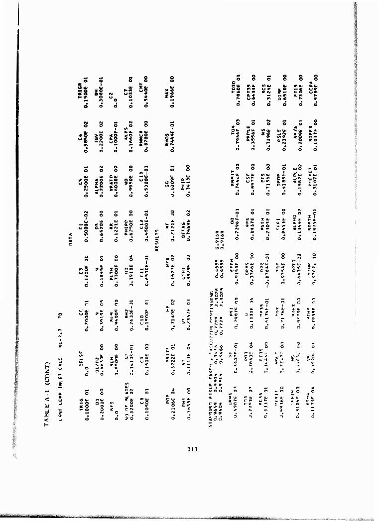
:l e i
s •<* op ÜS -»
o o
K « < «
o o s miu tru. </> UJ IU OO mm w* u. O t- « t- m or <M £-•
r- ui m o« • • • •
o o o o
IP UJ
o o
h urn
«e
ö a i
m u>
SS i% i- fv uO
IM -
aib JO "2
EP
o
i/i >
m ^ <M P4 M4 o o o o o o o * tu « v
OU. _i u. 1/) |U 1^ li. N. UJ lb lb ►-■f C-0 z « jfM • o- a f- « Ktf< 0> M V 4 o om
o- 0.« ■* am so
S8
IM o o ■a P4 o o o o e
m i o o
UJ CIU UJ -• UJ U. UJ
« o »- o OO uO 2 & m xo «e SIT e c o »• ^ a <M $s » o o o i* J<M ff IP «• a m
o o o
o o o o
— it u.ui i/iuj aib IJ irt^ H--C CIP
a * v — c — h- CP h- ^
l\J UJ o
a ui j IM u. r- «« c« ■■ a - — m
K O
K UJ
IM e UJ
eg o ip
0 ; o o
mo w OIM OEIM
o o
CUJ ao
SIM
o I
IM UJ — o UO
IP
o o IM O
UJ
« « »- ■»
OU. (^ UJ C * a N
c ui m fvj V » » r-
■0 « • "* --
O o
o I ui a. * _i -r < m
o x I ¥- lb a IP c f-
o 3 O C s o
ftj « o
fv o ir. ip
o o
X o r o
i
o o
IM o
C 1
o e
3 lb ^- IN. •C
a if. IP lb lb IT UI o u. a u. h> lb a ib UJ
m o o o
IM
UI »IP
OD
lb X o ►- o .jm C K
lb o «
lb -O -c l„ IT
4.
ip IP ■» ■» t •
o o
lb IP UI IP
o- •
a <b Of
m
B. * c m
•
or ^ K IT
f» a- •
Q IT O f
•
I " K a
IT
m* IT o — r o c o
«.' UJ UI U' IM lb o OO ?» TO 1" r o PJ -c to
o 9 c * « i\ f » IM
o OC -a
1 UI c ■»
i- m > IM
OP ^ C rv.' »v TOG ■« (V (* c -* ^ r* n T* • • c o n c r^ IN fv IT 1 » w •H — u UJ m 14. M ai a., u. *- I/* "^ cc a «r C « r a 7 a c r »^ c ^ c »- » r ceo a i^ v« ^ C r«. ^J K ^ * f a-
r- h- • • • •
t>
H Z
c c — o o O c o
^ xi* « o lb
C 1» jO _• u O >. « « IT -» IT - * «■ ^* O i •
o c o o
m uj C !■>
< a s o
w o
si r u-
< o H
o u- — o * o »- o
o o
OO - O u o *
_■ IM
CCM «1 o
ilb o
u o C IM
CC UJ op
■*
o a O Hi a « r m
a. r
< ■* * >- o —
or a o IT a 3 • • « o o
c <r -t or IP o « « * OP» i • • «CO
3 o
^« O o •t Cl «- O I o c
IP tm -» IT uj *> U u. u T u. a i- U' £ u. •» «- e a » 1 1» » o > ^ **! e ■rf
m J or —
113
ii »[«H.r.liimiii -

m** WWJ<*''?3MW''^»s''wre?>TOm«»t^«iy.g^^^ lvlMif%»»^B»^r»^<K*lWii'WICTWiWmWW^^^'g'^fe*<Sg ■ " Bsps:-'
^ «i o s o o o o oc 1 K O u UJ Ui S lb u> «g xo r- m oo KO as «. u<" ♦ « «M ►• ir O o e •» > »
m e p« o o e
o m ib
e e o e tf> lb 1/1 UI m NMU
C 0- c? u« *■ ^ — h- s« «m a» !-• «> a e •a Ci IfcfM
h- u« m O« K
ss
o c O 1
o l/l
ö 1
lb lb IU a u. a lb lb ■CO > o ■J o -o o O m^, uir £g u o "2 Jg |5
IT fM M •-• a « «f- ■ • » • • •
O O o o o o
fvj o o _ o o O o o o
.■fl I o e
Ui UJ cu Ui — ui lb u. »> o « O I- o oe o O 0" a i» OC z o « o sir o o o — i"
ir a. <M aO ? o li o Z m rg _| IV > ■* in a m
*VJ o M o •* o #v .•) o r o o o o
lb Ui •b o * rv ui lb lb — O i^ e at -* a o — o *• — C -0 uo c <v a M •~ ir u o S K «o c ir iv I iv IT IS. o »- «•
IT « M a < * *- M UJf- • • • • ■ —1 • a • o o o o O 3 o o
wi m* IV •* o s o o o O o ■t lb « >i O ki -J Ui l/l lb lb lb x. ui u lb »-f- o* »•» -i M • m «1 r> « m 1 un» « O
» a «> e. (« m OtO f- m f- IV IV «1 • • • • • • o o o o o e
o o o M m
o o o o Ui O ¥-0 b> I ^ «M — Ui u. u. l/l lb a tu & Ui M Ui s o vtm fO o r«. •J a Ui«l Jr u» uiir a -o «I K C» OL * w *« C IV m & "•
N m r- •» •~ m • • • • • t o o o o o e
o M m»
o 1
e o o o
O X? O Ui IO Ui X Ui M* Ui X Ui K Ui c ■* a ^- t- IT lb IV a « 12 «c Ui f^ WIO u. wrf -J ««
* Oi a ■» Ui * « m or * IV IV 1- ■4 rsi K ■H m*
f» f • • • • • • ir m e O o o o o o a
— o < — o o e o
i u lb lb lb
»* IO c»- —o o «- n D— — c er — w P i_' if
• • • • o ^ c o
1 lb lb — K * ff IM IT »- < — U «
O O o o tr\ ir * ■» • • o c
z U lb U IT lb f
o e
vj ib » * c i"
o i
O lb a t- C rv
o o o
O I a iv
a ui
e K
u. Ib IV u lb I.- o r «■ I n I c O
c v j n «r c o o r 3 a 4 < - o »v !*• a *v 1- —
X u. c M
o I- n
o-o-e T it* If — ■* ■*
? M IV
c r» I» C * ■»
■e < z r- f C t • — o o
o o
■" u i/i ^• a o
s
o IT I f* Ui
e » o x
o <s
K lb Ib P O a M
»
e e
s *
H 2
r o -* o n n o o a c. Lb
l> Cl I '"> < O v o c " _i o «« 1. o v « «■ IT * IT
c -- * m ^ r •
o o n o o
» 1 a UJ * •# »^ u
c o a *
c
o o
o o
c o X «
IT
8 £ > i« m
•—1 M o C M Mi •» o 1 a o o 4 ^' o o o < t — a.
r Uu ■N u C UJ X Ib c ib M Ib
Ui u — o c o H o u o a ■0 z ir a O c u u o IT o a »
l^j ^- t- O c ■ C i^ O tr OD * »v -> "" I*I ^i IN, ■^
< lb • t* • • w o o o ? o o o o
h
«K «> ►- ar o
K ac a tr ff => • • 1« m M o e * K O O o o o •- o so o
IA 1*1 < u T u Cl UI in ib V Ui Ib lb IU1
or f- o » U^ u «c u. <f i- •• c » m = o £ r a m I ■# ui m s f <r IT O 9 fk* m » O « « « ■e f- IT » • Ml
c » <r • • • • • • z • • o o o o o o « c u
114
IIM——^

. me^- ■ '-^ mmmmm^mmimm^mmrvzmm^ -E«!?, SS^K^^SiWRiW^^'flS-fiflf^^ .
= 8
e i
xe o o
«90
e o
2I i. o
o
e a. lb
«
o e
«I
o o
35
o I
«I •♦ S5
Kl o s o 8 o o o e o m mib IT Ul wuu lu If. IU a iu o^ m« uO u. « xc "1 ►- • »- « «« s« K ♦ o*
(0 a» *M M4 IU M CO r- um m o« ^• ir t • • • • •
o o o o o e
m ** M ^* o pM
u o O o o o •» lu m X 1 CU. »1 Ul in u. lu U. **. IU IU IU ►- M o-* z <* _i o- • v a "<
o KIT t v> c < M C -• o av a fl a> B^- CO «■ « ru ^- »
■rf M o o md
o o o o O m I
IU u» OIU IU — IU IPO «o •-o oo uo uo xo « o »IT o *> a r» a e ff o
IM -«<M >« O1 1*1
o o
m a in o o — o O O Z «M
" am »M « 1*1 o o
o O o •M (M M
o O o o UJ O (- o K 1 «1 M*
U. Ul l/l lu a iu a tu K IU z c oof 1- o O IT -i«" UJ <- z « oo IU fM & " « " oo a ■* o o ♦ or a. IM
r- <f f^ •» "* m m o o
«M o I
Ui -o uo
o tfl
o o
r* o 0«M
« — a <M
o
O UJ a n 1 (M a -c
o i
IM UJ — o uo
o o
1- ^ Ü ►•
a- ^ in u u. u.
o o o o o o
^ *t •-4 o IM •H ^ o
1 o o o O
c O I 1
rsi
O UJ iA Ul Z Ul M IU I UJ K Ui o -t a f- >- « u. — a o a a a
o lu Kl (/> m u. ■* -j" c - U' m O1 a IT IU rr> < (M a ■t «
g. a h- w fM go «M X (M (M • • • • • • 3
n o uo
o IU
X at
o c
I c >- o
U UJ ü8 o (M
I u c
c UJ
z IU
O Ul -o a a •- o
fv.C C I« V « m ■» C •
c
o c
M Ul s o
o c »M
X o -I o a. <*
t o -JO 01 w
ri c c
C IM < c S u.
u O
o I
u in ■a
o ce
o o
» o uo
eo IT O
CM IM u IT « o O c IM V • -0 « X u. IU Ü IT. 1"
1^ *• m Ul o *4
r\ X a a o o r. i- IM -^ i- « • « o O -t * C
IM •r ^ O
1 a IT
•0 UJ • -0 —«
r%. 1*1 9 c m o o o Q Ul ^' o
Ul in or in o X ui U' ■»
(*i * o IT V ■Ct
t fM r* 2 K IM • u- • • O M
o o 1 H
z lu
Z c a
4 I u. O o 3 c K O IM ► a; u a —i a ■» IM < ^j tt IM ■— ~» <
K < mt u w 1" ** > • O o
C
Ul Z
IU K ^■ ? T •^ 0 NM
■r o ^ <? « o o »- a 1^ X
a a r ui »> u o a -c T * i^ v
n a 1^ o
o o
I u u. U f. u O
o
IA Ul x <■ or * C m
O O
OU. a IM c <
o o
a ir o c
a u I ff K If e: f
— ^ tt,
1* 1" u o
ÜR? a *■ f^ h- o ^t ^4 mm ^* C c ts • ■ e c o o "5 o or X «NJ rg IT 1 1 V a »- ^. u u. (^ a-1 X U U4 U- a M. U" ** K lA ^ a a «■ o •o O X X *\J ? ? 0 o — r^ c IT c T o k» fv. c r> C fn fr 0* f*- 0 0* p». 1 0 K u c o K «rf ir f- s- < z
*r IT • • • • U c X»- fw O C c o o O
C • • c t-
— o o UJ h- c w^ J; r c -i c O c »r> < ti. « O c c c O n c »- >- >c er c 1 tr < < Ui -t 4 u. u_ t<\ u rr» UJ ti- u u. Ui z L
o-c a. o c if »- t^ —i o C ^ a e am * • • o a «» u. 4 2 <r a N. > ^- z u o c r^ a ir y r- 5" 4 a c
z f^ ^- • r ** r^ UJ UJ • • ►- c V r? C e o o C r < »r fs.- z UJ
»- l- u c c r- i c (r o- *- 3 • • o (^ «^ o o 4 2 UO
K O O O o o •- o X o o i- y vT a- >— 4 c
u. f a.» K> u. f* üj V u u „ I U' X — a ff c 0 (_> C; UJ w4 u -rf h- i* UJ u
^ T - O ►- 4 a X r- lii X > f^
rr ir O ff ^ fr c (T < ^ < >r h rr a P- .-• o r- c o- 0 • « • • • • c ^-
1 3 C o -> o a <\,
115

ft
a
I- a« 11 V
m» pri m* o o O o o o o
at i H- (SIU Ui UJ X UJ Ui »a zo h- « oo X m KO ceo N o-» ■» « m »- m o o ■» I *
o ■^ tf\ »4 • • • • o o o o o c-
(«1 o ^ O o o o o o o o o o < m UJ ITUJ vi ai UJ irt u a. uj oo m^ h. ao u. K — h- of- >-•* >- •* at O «m »- M — a m *\ •M -^ a, rw ru
f- or- m* o r- K irv • • • • * o o o 1
o O o
PU w- (M o »« o O
1 o o o
1 UJ Uri a u. at u. Ik
> o < o _/0 o O VI f- e o a o < -i I o O » M ry oo ■c Z 1- I ■»
«J ~4 f* a: K a r-
m _« in mm ** o o o o o O o
■» UJ < >> O UJ -IUJ 1/1 UJ UJ UI ■v u. t-o oo r «■■ _l IM • 1" a M
at r- 1/» »T < •* Ql« (NJ a o m 1 O- O a O
— INJ o o _* ^ o o o o a o
w | — u.
a o
UJ U.' O UJ UJ u UJ
ire < o » o C O o o ,1 a. o oo I o « o 3 IT o o C - o
trt a IVJ a o o- o o o I Cl (NJ _i (\J >* a «• ~* Q. rn
o o o ■M fNj .M
o o o o uj O ►- O 1- 1 ^ M UJ U. Ui l/l u. a UJ a u. M UJ r i" i^ tr» •- o c — jfM UJ u^ z <c C- UJ 00 a * < ry c o- u; m CO p* a o- 0- a m
o or m r^ I\J
rg o ^ o «H o IVJ o o o o o o O
UJ u UJ D Ui IM UJ UJ UJ -. o m o a — Q. O "■ t- K ^ O CD oo O ^j at iNj — If o o I ^ < —
o 1^ ry 1 <VJ IT 1 f r- >- K> tf> * «M a * * r. FH u. r- • • ct • o o c c O ^ o o
o 1
o o o o o
o I 1
OUJ \A tu T U •- UJ I u »- u. C 00 0. I-- >~ m. u. "5 a. *- Q. 1>
u m ui a- u. -0 j ^ O IP _. a a m u tr < ■* a •»
m o oo
c or D -
-• o — o o »r
I- «Si I J t- m
o o o o IM o o o o o O o
z C 1 a u w- U. O a. u u_ >- u. a u. a. -0 I * a tf 0( IT a tr X u- UJ O" a 4J c — >- r^ c eo l- ff
fM 3 m K fM o CC IT (•■ m OO L- rr, 0
O UJ U. UJ IM UJ Ui o O O 2 - I 1 I o O •c o C -J o 1 o o o
o (*■ * * < — a (M rr\ ? r^: o —
IM 1
7 -• Mt
■TV •— ^ *• o T IM (M
o •4. i_ a J-
O 0- 0 J J
r or X c • ■ — 3 c
H j<.
o o ^, o c -5 u o
ui Ui C u. u IM O I -5 < o T O d <** _l O »4 O o ^ -o a IT ^ IT
o -i -t (T . 4 _* • o • • « • o o o o O
»- - UJ UJ m 'U x UJ UJ UJ K- ./I ^ r- a ir- C» IT» O m <- a. •* 3 'l c r^. - -f 5 m r c rn IT u K -« J~ K O
i- n o C O o c
o o
o o
ffl < h
O UJ — o a o >- o
o o
-^ UJ O O
o o <M
D iv. H < O a -J CD UJ or u.
o o o U O ir C "M o
-n o • • z o o
a * — -•
o
i*\ u
a —
a — u T * a ao
►- o o o o*
a c • 3> • r • • • • x a • o •
c ^ o -^ o * »- T m I < h» O ^" O C T y a • » • • «I o • o •
u o
T u. Qt I*1
a
ne
-•'I ' - - -ml ;' i '"- --■-■■•- — - ■

■4 «4 mi o o O o O o o
ou> 1
m S 1U UJ ~o x e f « uO KIT «o BO f* «j* ■«• 4 <M t- <l\ o * i « — m o *4 * p4
M fst ~* CM o •4
O O o 1
o 1/1
o O I
Uy 41* a uu a ui IU « O > o < o _iO oo l/l cc (J lf\ o o a o < * xo OO'
«Ü *- r\i u o « »r- I •«• m fNi ■4 « «» a r~
m o •4 e e 8 e 5 e a e Su. miu MUi Ul niu a. u< o • mm UN u.r- M« 08 »-1«> >- * a. « • — K — «« a m IM M «4 mt* N
f- ON CM ON *• m • • 4 4 4 4 o o o o o O
m M 44 o o e o o Cl e
♦ UJ « K O If _i tu 1/1 Ui Ui u. V.UI UJ UJ »- « ar- ir- _lO • ♦ am
«4 a « a in in «♦ om M a o * a 0- e ao (~ M r- "• »4 art
^ INJ O o ~* 44 o o o o o o
I« 1 •4UJ
o o UJ UJ O UJ u. UJ u.
IT O « o 1- o CO UO •0 a tf; u o I o « o TIT. o oo M a
m o. * or o 0- o O o I f» IM _1 «M > <o o IT F4 a m
o o o «4 M ^4
e o o o UJ O >- a t- 1 ^ *4
•- UJ U. UJ V> Ui a u. a UJ K UJ X o l/v -0 1- B o < jfg UJ — z a> ON UiO a o <M O0' of m « r* o a- » O. m
-0 « < ru 44 rg • • • • o o o o o O
IM O e4 o -4
o O a o O
IU UJ w C Ui fM UJ — o m o a — e. O — O o o C «M ac nj — in OO
o in rvi I "M in m ■0 ^4 0. O -»■
O O
eg O
15 ♦ < fvj
U. m o o O
X o K O D —
-< o ■4 O
3 U; « m
O Ui Ui UJ IVi UJ U' o uO z * X O r o O ■0 o m _i o « u O o
o ir <c < « - a fvj (^ a- M u —
UJ K <r I o >- r>
O
O O m in
rg IM
t • o o
ao ec 15 -4 -. r -f ■* — r- r> o • • y ro M
c_ f^ m u o- 0
•t * ? «• aj c • • — o o
-4 M »J o m 44
o o o o 0° o X 1
O U* 1^ Ui I Ui 44 UJ I UJ t- UJ a i" 0. N I- o (A. (4\ a. 0' a. oo * UJ f**! mO' u. in _l -4 o «
o 0' 0. 1" UJ iA « ♦ at -r ■e *4 44 oc 44 44
o o O O rg o o o O o O o
X O 1 u UJ 1/1 UJ a UJ U. L. t- a. a UJ u. m T * a m c <£ a <s I m UJ C a -c o ■c 1- s o« >- 0
rg Ci i" r» nj o 05 OD <r n' a1 » 0'
o o
O1
o
a I*I c o
in
o
K UJ on a o-
o o
o» X rg
o o
at UJ I o- *- oc x a
H Z
8
< u J CD <
o o M c o -1 o o UJ UJ C. UJ u
IM e X « < o IT Cl c. m _. "3 »4 u u ^ * «e m * in — 4 « MJ
c • • 4 •
(5 Ui — O ac O i- o o
C rg .4
< O o ^ (C u. OD UJ
'J OO U. "5 in C rg o
m 44
3 • 4
r o o
a if & m
o
O UJ
•—• «4 < — o
o o
I r- o. N
uj c o * -t -t u m u\
fc • 4 c o
< IT r»% ►- » o
ac (r a tr (r • 3 4 4» MOO*
o a o a a N m X < r* K o e » o. ? 4 . • «I o o • >- • 1/1
*4 * o o o »n o
1 o o
IT o o o
U. Ui rn it m uj UJ UJ UJ in a. o O -■ •- * -i -4 0> — ac —
o a. -4 UJ -t 5 * X« >« eg B r- a «■ « * m in f * • • • 4 • O o o o o o
a 3 m 141 44 o o l^s K o o o ►- o X o O 4M Wl m 1* U. X UJ m UJ (41 UJ K UJ U. UJ
a o OB oo. UJ o u. • >- m c 3 IM K m ac IM I rg UJ rg >m a. If o m ■t rg 0- «» in K IM m m Oi n 4 t * 4 z o o o o o o
117
MK*M M^a^MMHMHM -■-
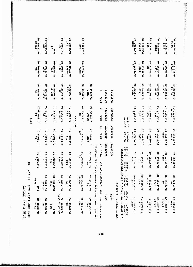
'"?*Hmpyw*<» Rm*»i^wMi*JW,'« <bli'.!iwv*L*in^!r'iiir^^,"-'n:."■■' ■"■'■■"n-r;irv ■,■;---. ?'*«?gwy?'^r.!ft^e^w^g»^mia!i^.'a.s: IWiUWWW—WT^BWUlBHWI'Wgg-'
pri ■tf M4 o o o o o e o a 1 *- IS UJ lu 4b X. IU Ul
:§ X o r- « oO x a mo fM o* * 4 •
K ir m4 O e ♦ I 1» ^4 m o «4 in P4
l»> O »4 O o o O O O o o o
o « miu ir> ui 4/1 Ui UJ tf\ UJ a u. DO m -« OK u. (^ x r- i_) « t- IP f- «0 Of .0 ie a> •- V u«
Ml a » m •- o- UJ fvj to N o« rg C. -0 f^ ir
•c o > o « e a. o
(/) 0. UJ JO
■0
o o
Ot UJ
Of »
o
o
UJ vi m O r> X IT a. h-
o O o O o o 4 u. < X 1 D ui -J UJ ifl Ul U- UJ * u- UJ U l-IM o — z -• ~4 W • o a — (^ oc r- c t/> ir < 00 o «
*VJ o. -c o O.0- O rr KJ f fNJ h- ** 0>
P4 (\j o o -H •4 o O o o o
m o i
o o
UI UJ O Ua UJ Ui UJ UJ
m o < O t- o oo u o •0 a « #4 o «0
oo I o « o sir o Ü o ac u. VN a IM a o c o e o I M ff u. r*j -i N > -0 0- in #4 a f-v « < • < • • • • • • • I\J * a o o o o o o o
UJ O O
o o
o o o «M r\j «j
>- o o o 1
UJ o >- o M UJ u, UJ (/) UJ O. Uj a UJ X UJ X 1" u^ •» H- rg o 0 _) -» UJ IT Z <T (_j CO u, r- tt rvj < -- O "J ac 1*1 OD o o o a a. ■*
r\j o ■«4 o M o ro O o O o ? o O
UJ tu UI C Ul ISJ UJ UJ
-O no o- — a o — o K fO O ISJ uo aivj QC IM _ IT OO X — < «
o m M I IM in >/) r» t- m in < Ml a. <c ■* »" -- ILJ h-
O i u I 1 o ou. ^ UJ I UJ m UJ I UJ h~ UJ o o « a i~ t- O' U * a a a tc o a U. (^ IA * - tc Of
o m* 0- a. * UJ u^ 4 r*l 0C (VJ
o r o> J> H4 a- ^4 M
U. K K • • • • • <c -o o o o o o o r- r-
^ — o * »* fM o o c o o < o UJ UJ UJ UJ UJ 3 UJ
m o I ■» I O o «o M O •O o o o t- o 3 - — o fsi ^ m _)m P o m l<i
o m o o c o (M o l) <o o o 0 o o n ISJ IM IM IM I C 1 m 1^ O O U. U- CO UJ O u. u. u. t- UJ a UJ
o ■4 J * u. *£ X -C a oc a a- Q. ly I m o O J- •» Ul ^" nc -o c ■» *- (\ o 00 ►- f • • (V1 C 5 f* o 0" 00
^ m* IB * i
o 1
ir
OD U -• — UJ • IM z - -
pri in o -4 ■Jl IM (^ o o 1^ o — o- r ^ >f ■J« Ml n -> o o o
1 o
u o o «1 UJ
a IM o
1 Z fM JM 0 o ^ i
o 1 X
o ra U UJ Ul UJ M UJ u X UJ u. ^ »« t_ JJ UJ K u. X UJ UJ u cc u u o z m y o I O o -t «0 IM K to m « a IT o -c c ^- I l»l
o « ^ o (C o oo « o 4t' a ~f 3 * CJ IN. c -0 X IM 4- !>■
o o tn c * « «H IM *~ a c. z c - - 0- wrt r^ •0 If I -»■ IM m o- pg u - If > ■ fcO U 1" ■" f^ -- -f r^ OJ 3)
• • • • • • o * * • • • o o o o o o o 1
tl r 2 x e c • •
o o c o o O
h- t~ o ^ o o • 2 a K
»M | o o ^ o Bp4 4- UJ
X U.
u _ >r o o o 1*4
UJ
a o o c o UJ o o 3 o c o o o c o
u 1 *~ o OJ ^ Wl f« 1 IT
VI UJ UJ C UJ Ul t- UJ UJ a «J u.. ir v u UJ "" UJ iri UJ UJ u. u. UJ
_1 IM o I o « O a o « in m < -J » o- Q ^ c «» h- —J -J IM e —- ot i-
UJ o m _J o -4 o o a •o MM «M « 00 • • « -^ a IM OJ IT Q * X 00 > — o
u
o •v o <c IT * m h- < ■« Ul o < o o IM OD f* X 00 * If
H o ^ ■» OD PM IM .^ > m y »^ m ^- •0 a- IM
• a • • ■ • • • •c aj t • • • • • Z 0
o o o o o O o 4
UJ z
IM
< g- op o n O o o o
^. 15 ■^ ►- ff- a)
0 UJ -1 z
vt u.
Ul 4-
3 a T O 00 00
Q. o- 0- •-« o O M Ml •»■ o CJ o ■a 3 - • 1*^ m ^ o o l»4
•-J o o < O o c o »- a o^ 1 11 X '_> o o r> o K '■J X o o
_J a ac *- ^ 40 •» 1
1 o u
U UJ w JJ IT UJ (O UJ U UJ M« UJ 3 z u Z u K> U.1 ■n ■11 K u- X UJ T UJ
< M o a o «w o oo a ^- I a- (/I 1£ ^- a N C * O X4 U; a* a in K ~>
t o o u. u. o m o a rr\ O Q c a 1^ 3 IM 1— o a ■» 2 fr\ u. 00 > 4f
■w ►- o o ID ON o ^ iT M < a or i^ -»• o- o If. * —J cc
J IM o (*l IM m < ^ r- IT r^ IM (T m 0>
z UJ u
• • o • • • • m UJ > 0 3-0" • • • ■ • PQ o o o zo o o O -g u at i" • • o o o O o o < o
I < or Z
< o o
H ►- UJ un
11«
^^M aM j—-"•■ i^*M±j^^_ .^ ^■LJ,...^^-.,:-^^..
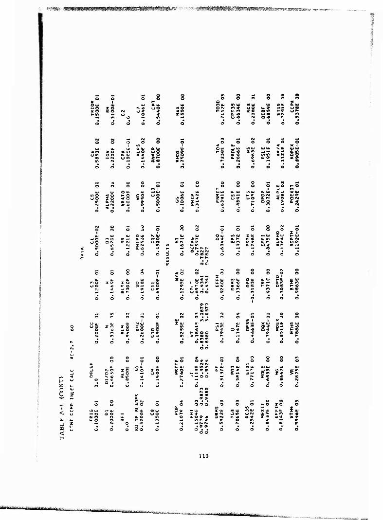
«,«•$»•,; ■ /mmi^iK^^^f^^^^v^^wsf^m^f v»j^»S^?T^T!:5;<^.,W35Mr •
ace
O
•CO
o I
X o s o
o
>o oo M (M
« o o. C u o
ULI
o
M o
«n a UJ -I o
o o
S. Ik
a o
o
^ NJ o o *4
o o o o O cn 1
UJ Itl O lb UJ — UJ it\0 < o t- o OO OO o o I o < o itr o
IT a. rsj a o f o IN _1<M > « 0- If
o o
5S
o I
Ui uttf no X if
IS o ISO
m o — o o o o o o o o o
o « I»>UJ «A IU l/l Ui IU IT UJ a ui 0<v m* uo u.» *<-< u« 1- IT K m B« sm t-9 u»-
■M a « m » m UlN m K o * IM a « f- IT
m «4 (M M« M4 prt
o o o o o o •» UJ < K 1 O UJ -J UI VI UI UI UJ «tUJ UJ IU l-«D O « jt in -J "- • •• a £
m a « « m m «N oo M a <o » a » a » K IM <0 "* •M •
UJ
— * I —
o o o ■4 IM «-4
o o o o UJ O l-O *- I •J — UJ U. UJ l/IUJ a UJ auu K UJ I — \A — t- v o m _i e UJ »• r » u <r u O a t- «o OM a m w v* o o » a ♦
■0 m r- m M «M
ry o — i •H o m — •^ •-» o M m4
O 1
r> o -3 o 1
o o o 1
O o o o o
O X 1
UJ UJ UJ Q UJ IM UJ UJ IU OUJ t/l tu X UJ >• IU IIU >- UJ — a m o Of — a. -5 -• o H- «4 iSt- Q * a f 1- « u. in a.« a CM o o O iv 0t IM — IT uo r r- < » * UJ 1*1 l^ * u.^ j* o <r
o (A fvj I IM IT l/l •o ►- IT n <y tt. f- ui <r « m cc — ir <0 •u a. <c •» K ** UJ r- r^ r^ •o r-t -4 «D Ml W4 • • • • -) • c • CM IM • • • • • • o o a o o = o O CD K o O o O O o
l/l f- f- UJ a
• • OCi
_ w- o ■» •■* ■,sj IM r> a o o IM o o o o o o
1 < o o o
x o o o O
O 1 o
UJ u. u. UJ UJ XUJ Ui-t -t U. UJ i/i lb O UJ U. UJ h- UJ a ui (*1 o X ff I o O «0 — o in t O l»l Kl u. o a « o. m a -< a m xm uo ■c ►- o 3 - — o o> _ 1- * <» UJ c a * a oo t- i^ oo t- «
CM J -J 1*1 »■ uir IM h- a • • IM O l«l ~* m o CD 00 «1 f- <o m-4 u 4 OO 0- 1*1 i»i (T m IT • • • * • • •
O o o o o a o a o o o o o
o ■c
U ui u o
o o IM
o — ••4 o r> o IU (M Ui UI
I o I o o -1 o s o oo » <r « — e
a IM u —
« «i CM i" oo o * ■M «*i o o o
UJ O I •
m i»> r> o o o
1 -5 o
X UJ U! -• UI UJ m tu X Ui UiUI a UJ in wi m h- a m a ■» Q- I « ir •a a •» 3 * O« o ■» l.-" >■' <D CM i- an a o » ■0 » V' C • in > — «D 00 ^. «^ -r K e ^ • • en in • ■ • • • • o O oo» o O o o o o
8 ^
o c «rf O o o o o
u. UJ O UJ UJ IM O x c «T O <r o O 1*1 _J o -rf u o ^ * ic in •t m
o — J (O ~* • 3 • • • o O o O u
< w iJ m <
•-» o C IM H)
o o « o o
O UJ — IU IS UJ 00 u; — o Q O Ml o uo a: O o u. u. o m 1- o o IE DIM o
rsj O m *4 • t • Q • • a O o z o o
or o a -c
o a O U' a. f-
o
o* -t IM IM
UJ in m
» - o o
o in o f- oo CD eo <r ^
o • • o o o
a o a « m K # -< r-c- • a » o • •
o o
* o o o in o o
in o o o
m UJ in UJ uj UJ IU IU C * t- K jm o^ K m a — Ui — om z« >^
s h- Z 00 « 06 m K « » IM
l/l Z UJ a CM DIM ff
m
m UJ o m
o m in IU OIM a ■»
in IM
o •- o
z m
o z o U. Ui u m Ui «
00
o
o X Ui t- «
119
•"'""—•' - I mi
m,m^m^m—
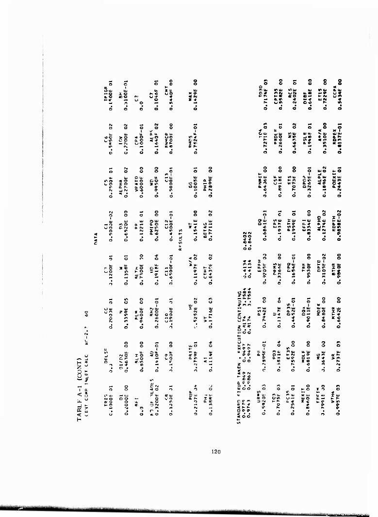
p- ^4 o o o c o o o
a i K Ou.- lb % U IU ~o X o t- « t o X 0> 0.0 joo ^' o -t * < fM >- If »-• o * z <r
m* .n o w* IT M* • • • • • a o o o o o
in o M O s e O O o O e
Q 4 m uj «r UJ mu It) IMU a UJ C ♦ •nra «JCM u.» -» u« ►- r- t- • «O « — K N u"» «• e. ir ■» •- * UJ IM <*
r» uv> N o o ^- ir
41 C
rg ^ fM O p4
O o 1
O o o 1
u* u a i» Ot UJ u. > o « o -jO «JO 1« * c o a o < 4- t o O M •- 1% «JO 4} 2 f- 3 if
f^ -^ a» V f
m fM N p* e «« o O O O o o
♦ u < K 1 CJ UJ -JUJ V) UJ UJ u- V UJ UJ UJ y- ** oo »IT -J« • O a K
f^ ac« Kl w>* « — om fg o. « « a 0- IT s »« »- M * m* in •
-- fNJ o o Mi «J o o o O o o o o
O UJ UL r- UJ UJ % IT o « o 1- o OO UO IT a j l_ o I o < o •X "Ti o C O — o>
IT Q. fV. a o o- o OO X • M _| C\J > -0 o- in p-
o o s |M IM -4 o o o UJO t- o *- 1 .i
*" UJ U UJ i/l UJ a UJ a ui K UJ I <0 mo t- m o in -i« ui m so o-< UJ^ a « <p o •«• tt. •» a o ON • a« « c N m »4 <M
rj o ^J o ■i O IM
o o o o o o O
UJ UJ UJ O UJ fM UJ UJ UJ — r> *\ o a -• o. o — o ►- ■4 o — u o C rg a CM — tr uo X •» < —
o ir IM I IM m uo IT ►- r- < IT •o -^ a « « f- ■^ UJ »- K- • • ^ • a) •
O o CJ o o O O C ul
M ^- o * M 9 o n o o UJ u. UJ UJ Ui
i' O X ec i O O OJ -o oO m •- O 5 —« -o
IM m -j 1^ o- cir ^^ <r r» ** « X m
m* Ml •4 o IM IM o
1 C o o o
o X? O UJ VI UJ X UJ — UJ X Ul K UJ o I—t a K *• » u. * a ■* a. •
o UJ IT mir u. m jf om CD ff ao> ujm « IM 0£ «
IM fg ■c •M «4 CO «M V o o • • • • • • ■» * o O o o o o • e • • o o
o o — o IM o o o o o O o
•«• ♦ I 1 O 1 ro rr, u. UJ V) UJ O UJ U UJ >- UJ a UJ — M u. IT s « & « a o o. in X o * * UJ o a « tin K m o o t- ♦ ff • Pg cm « in (0 « n o » m er> m »
M i^ o ■M »g
r> o o o -5
U UJ UJ UJ IVj UJ UJ o o^ T O- I o I o ■3 « o m -J o cr a OO
o m a. -t •0 •M 0" rvj t* c pg O -" > —
o
0 " u *
o o pM n M« ■» o o c
1 o UJ O o
O u. *" u- UJ IM e I o «f o a o or » * o m _J o ■M 1- o a m fc- ^ ^ « it, m -» IT < •- -i * CO Ml ■M f—»
o • • * • • •
— o a o t- o
o o
—• UJ o o
o o
C eg «g < o O -J et UJ at UJ
o U'O ^. o m O »M "j m |M n • • «. o o
a. C UJ a K
o IM
— Ul I X a ec
* * O «D » y m in M- r^ r- O ■* ^i M O o D • • C o o O O o »mm m I 1 K »4 •« UJ Ul in UJ J< UJ UJ Ul a UJ h* irt rg f- a IM o •M oo X <M 2 a 4 3-» om D ■M X s t- ♦ a •» ■» ff ** •»• o * X « «j i- r- r^ r^ * ff CO «
«j -* « • « f • 2 a it a o o o o o o • • -OO h- 3 U (-« * o o o m LL r* K o o o o a o x cr i» 1 in u * -t u U-. in UJ m UJ UJ UJ UJ UJ
» a a IT 0 J— »- IM -J ff 15 m at f- » • • ff a ■M UJ ff a ■art z * > m o o «1 « in X « ■0 r-
z INj if* e- •0 J^ IM UJ • • • • • • if e o o o t o < ff rg >- -t *
a' CD a c e- = • • rr^ 1^ Ml o o m K O O O o o i- o X 1 O
vo IT <* U- X UJ «i UJ m UJ X UJ u UJ X UJ
a O om U WJ UJ O u. vri K r- c c- <n 3 iM t- f^ a * X •c UJ ff > in a — -t ff o in * ff ff * r~ r- IT 1- IM « K ff O ff ff ■ • • • • • z • • O O o o 11 o «« o o
120
mm* mtmmmm MMMMMM

Ulli
KIT
m* pM o o O
1 o e e
UJ tu 1 Ul Ui z o f- « l_lO X - mo i\ «J* ♦ « ■*
u o ♦ lO m o m* in •« t • • • •
o o o o o
m O «M O o O o o o 5 o O
a « mu, ir. IU i/> u. OJ il\ u, a iu ON n « Ui w U. N — <t «jir *- 0- i- « aO c« »- ir ut-
—t & ^- •* -o •«• h- u •» rg o* K «>
M IM ml »M o ml
e O O o o o 1
IU IU IU a u. a u. U. « O > O « o _)0 uo 1/1 IT uir o o a o < ■r 1 o OI"
c — IM uo ■c ZN im IT IM a« a t-
m* N ■4 O m* o O o o O
IU < K 1 -J U. v< U. m u »- Ui IU U. o ■# ? w -IIP • i« a -r a in — ^<» < a oo a -o •» a » « a f
IM « »4 ee f
•4 IM o o pN «4 o o O o o o
m 1 M IU
o o tu IU ClU IU IU Ui
IT O « O t-o OO uo <> a i" OO I o < o »^ o tfO — IM
IT a IM ot o c o OO Z K M -l«M >« 0 in a IM
o o C •* IM ml
o o O o 1
IU O -0 M UJ U. UJ lOU' a OJ a u. K IU X" V.IM ►- IT C - -i « iu 0- r -• O ■♦ UJ O a "i <o- O -» a <* O1 o c * <c a *
<e <B ^ m IM
IM e
— o uo
e
o o
O IM in ■o
a <M rg
O iu a o — (Tl Z IM OL «
o I
ml O un
o o
o i^
ml p4 o * pri IM IM O o o o o « o
X u O
Iu IU TS
lu Ui tu m O » K o c -o * 1- • uo ^■ »- o D — - o IM z n
«M IM -im IT u«-- ml 1- o ■4 «f- «4 « ml t. « • • • • •
o o o o o o o
Mg IT o pd ml IM K
O o o o n o O
u tu IU Ui IM IU UJ Z iu IU o u o z m X o z o o ff M « IT. -iO •oo o o ■r ■^
r> m »•» H, — a (M >- *, IM m a IM u - IT > -
-4 m4 ml o ig rg o
1 o o o
c O o
Z 1 o tu 1^ IU I UJ IU I iu K Ui o ♦ a K 1- l»l a < a 00 a » ^- iu m *A •€ u _j o C l""
IM 0- a. o UJ rg < rg a f IT IT h- fM 00 ml QU
V O- • • • ■ • ff tu » O o o o o o • «0 • • o o
o o o o IM o o o o r O o
a <> X c 1 K OD u UJ V u. O Ui w u i" u a iu »■ » IU -N I •o a K a r- a 00 X ■c in m IU « a <D Q « l- ■L c m t- IM • • O (*\ b •C ec ao o o o- m • • IT
1
m • tr • o o o o o n
•-I «4 o « « Z * i — rr, m o •* ml «— u o 3 ff ff o o o o c o ? ■» * IP 1 ) X IM -4 IU IU -1 UJ X u u. Ui ar u 1- Ifl IM ■n a O -» c o- T IT z a .» 5 ■* L. MM c f I lf\ t- o- c ■c *. 0 m* IT. B * 1 it u (r 0- f^ ml ■» c a IT
t »• • 1 • • ff • i- f- r- o o c o O O • ff -on
H 2 Z •« P U
•«^ UJ
„ z i —
<
<
o o ml o o o C o IU IU O u
IM O z o < o a 3 D W -i o •^ u "• ■>« « am ■t Ifi — ■» n ml
o • ff o o o o
•r
a ir — —
u ^ * o o o u ir ir o o o c o x r- f- i u- u. Ji * IU Ui r-. j. .V> U UI u. ^^
<r v a a c t> »- (M o o • • ff a o Ui 00 c -> i. m
o r> f^ OO ^ i a •u
a x o u
z tu u
M4 o O r>J M4
O o « o —j
o t? tu •ff u1
A Uj 00 UJ •" "3 o o MM o u O a O 9 u u. O ir i- O O IT C IM 0
ml rg O ■ff • ff ff O ff • O O O z o o
•t o o o
a O iu MM U. a f- z ♦
o a o m
IM — • O o
< o — l- * IT
oo a> a c* a ~ ff ff m I*I m* C o m X o o o o o 1- O » o o MM l/l IT Mff •» u. r UJ r- u i» U x a U. I|i I 1!
a oo U 9 IU o u. rg 1- « O 00 — 1- XJ ü 1^ I a > O « 1- * w o IT * IO P < f- 1- m f^ rg or r- 0- o a 0- • • • • •
I 121
MMkMI ^MMM ^Ug M^ -Jl^l^^mltmmm^ i aiiiii i

■-*nm*im&mn%mmw9mt.m»m WKmmmmmn
LIST OF SYMBOLS
A
B
b
C
CD CP C» Fm
fi
g H
IGV
i
J
M
N
Ns
P
PF
pLE
PTH
P
Q
q
R
Rc RcOA SF
U
vm
va Wac
Z
Area
Blockage
Diffuser axial width
Coefficient
One-dimensional blockage factor = 1-B
Specific heat at constant pressure; statf'.' pressure recovery
Tangential velocity r n u
i - i 1
Modifier factor
Acceleration of gravity
Enthalpy
Inlet guide vane
Incidence
Mechanical equivalent of heat
Mach number
Rotor speed, rpm
Specific speed = (^Q"N)/[jCp T0 (RCoA(l'-1)/>'-1) ] 3/4, rpm f^^/sec1/2
Impeller rpm corrected to standard conditions
Pressure (total)
Prewhirl factor
Diffuser leading-edge total pr assure
Diffuser throat total pressure
Pressure (static)
xnlet volume rate of flow
Energy head, nondimensional by Ug/Jg
Radius
Compressor pressure ratio
Overall pressure ratio
Slip factor = 1 - {C$2 + Vm2 tan ßb2)/U2
Temperature
Total temperature
Rotor speed
Meridional velocity
Axial velocity
Rate of airflow corrected to standard conditions
Axial dimension
122
•*■■•*

jj^pgjISIjPijagiijW^ - ■ ■• ■• <im'WKmiiiiii!r^mm>vMam:mim>«?^t-v^
LIST OF SYMBOLS (cont)
a Flow angle
a. Inducer inlet flow angle measured from the axial direction
b. Diffuser inlet flow angle measured from the tangential direction
ß Relative air angle or blade angle
/Jjj Impeller blade mean surface angle
y Ratio of specific heats
A Differential
• Surface roughness
V Efficiency
♦ Inlet flow coefficient = Va/Urrns
T Pressure coefficient
Subscripts
C Compressor
cr Critical
ext External
f Friction
a Axial
IT Impeller tip
LE Diffuser leading edge
OA Overall
ri Rotor internal
rms Root mean square
T Total or stagnation
Tan Tangency
Th Throat
th Theoretical
0 Inlet total
1 Inlot guide vane inlet station
2 Impeller inlet station
3 Impeller exit station
4 Diffuser inlet station
5 Diffuser leading-edge station
6 Diffuser exit station
9 Tangential or wake
12H
i»'f'i I'laai n -—tm rar -;iM*liiiliiriii ' '-■ ■——■ ■ '■!,
Related Documents