Page 1 of 43 Surveying Survey Station: A prominent point on the chain line. Can be at the beginning of the chain line or at the end. Known as main station. Survey Lines: Lines joining the main survey stations. Also known as base line. Check Line: Lines which are run in the field to check the accuracy of the work. Tie Line: Line joins tie station on main line. Bearing: Bearing of a line is its direction relative to a given meridian. Level Line: Line lying in a level surface. Horizontal Line: Straight line tangential to the level line at a point. Vertical Line: A line normal to level line at a point. Datum: Any surface to which elevation are referred. Elevation: vertical distance of any surface from the datum. Mean Sea level: Average height of the sea for stage of the tides. Bench Mark: Relatively permanent point of reference whose elevation w.r.t. assumed datum is known. Height of Instrument: For any set up of the level HI is the elevation of plane of sight w.r.t. assumed datum. Back Sight: B.S. is the sight taken on a rod held at a point of known elevation to ascertain the amount by which the line of sight is above that point and thus to obtain the HI. Fore Sight: F.S. is the sight taken on a rod held at a point of known elevation to ascertain the amount by which the point is below the line of sight and thus to obtain the elevation of the station. Turning point: Is a point on which both minus sight and plus sight are taken on a line of direct levels. Intermediate Station: Is appoint intermediate between two turning points on which only one sight is taken to determine the elevation of the station. Theodolite: Theodolite is the most precise instrument designed for the measurement of horizontal and vertical angles and has wide applicability in surveying such as laying off horizontal angles, locating points on line, prolonging survey lines, establishing grades, determining difference in elevation, setting out curves. Transverse Surveying: Traversing is that type of surveying in which a number of connected survey lines from the framework and the directions and lengths of survey lines are measured with the help of an angle measuring instrument and a tape respectively. Levelling: Levelling is a branch of surveying the object of which is to find the elevations of given with respect to a given or assumed datum and to establish points at a given elevation or at different elevations with respect to a given or assumed datum. Reciprocal Levelling:

Welcome message from author
This document is posted to help you gain knowledge. Please leave a comment to let me know what you think about it! Share it to your friends and learn new things together.
Transcript

Page 1 of 43
Surveying
Survey Station A prominent point on the chain line Can be at the beginning of the chain line or at the
end Known as main station
Survey Lines Lines joining the main survey stations Also known as base line
Check Line Lines which are run in the field to check the accuracy of the work
Tie Line Line joins tie station on main line
Bearing Bearing of a line is its direction relative to a given meridian
Level Line Line lying in a level surface
Horizontal Line Straight line tangential to the level line at a point
Vertical Line A line normal to level line at a point
Datum Any surface to which elevation are referred
Elevation vertical distance of any surface from the datum
Mean Sea level Average height of the sea for stage of the tides
Bench Mark Relatively permanent point of reference whose elevation wrt assumed datum is known
Height of Instrument For any set up of the level HI is the elevation of plane of sight wrt assumed
datum
Back Sight BS is the sight taken on a rod held at a point of known elevation to ascertain the amount
by which the line of sight is above that point and thus to obtain the HI
Fore Sight FS is the sight taken on a rod held at a point of known elevation to ascertain the amount by
which the point is below the line of sight and thus to obtain the elevation of the station
Turning point Is a point on which both minus sight and plus sight are taken on a line of direct levels
Intermediate Station Is appoint intermediate between two turning points on which only one sight is
taken to determine the elevation of the station
Theodolite Theodolite is the most precise instrument designed for the measurement of horizontal and
vertical angles and has wide applicability in surveying such as laying off horizontal angles locating
points on line prolonging survey lines establishing grades determining difference in elevation setting
out curves
Transverse Surveying Traversing is that type of surveying in which a number of connected survey
lines from the framework and the directions and lengths of survey lines are measured with the help of
an angle measuring instrument and a tape respectively
Levelling Levelling is a branch of surveying the object of which is to find the elevations of given with
respect to a given or assumed datum and to establish points at a given elevation or at different
elevations with respect to a given or assumed datum
Reciprocal Levelling
Page 2 of 43
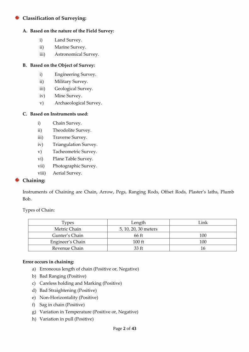
Classification of Surveying
A Based on the nature of the Field Survey
i) Land Survey
ii) Marine Survey
iii) Astronomical Survey
B Based on the Object of Survey
i) Engineering Survey
ii) Military Survey
iii) Geological Survey
iv) Mine Survey
v) Archaeological Survey
C Based on Instruments used
i) Chain Survey
ii) Theodolite Survey
iii) Traverse Survey
iv) Triangulation Survey
v) Tacheometric Survey
vi) Plane Table Survey
vii) Photographic Survey
viii) Aerial Survey
Chaining
Instruments of Chaining are Chain Arrow Pegs Ranging Rods Offset Rods Plasterrsquos laths Plumb
Bob
Types of Chain
Types Length Link
Metric Chain 5 10 20 30 meters
Gunterrsquos Chain 66 ft 100
Engineerrsquos Chain 100 ft 100
Revenue Chain 33 ft 16
Error occurs in chaining
a) Erroneous length of chain (Positive or Negative)
b) Bad Ranging (Positive)
c) Careless holding and Marking (Positive)
d) Bad Straightening (Positive)
e) Non-Horizontality (Positive)
f) Sag in chain (Positive)
g) Variation in Temperature (Positive or Negative)
h) Variation in pull (Positive)
Page 3 of 43
Engineering Materials
Strength The stress at which the material fails
Brittleness Tendency of a material to break before it undergoes plastic deformation
Ductility The ability of certain materials to be plastically deformed without fracture
Malleability The ability of a material to take a new shape when hammered or rolled
Hardness The resistance to deformation and forced penetration
Elasticity The ability to deform and return to the undeformed shape
Compressive strength Maximum compressive stress a material can withstand without failure
Cursing Strength The compressive stress required to cause a solid to fail by fracture
Fatigue Strength The maximum stress a material can endure for a given number of stress cycles without breaking
Flexural strength Strength of a material in bending
Impact Strength Ability of material to resist shock loading
Shear Strength The maximum shear stresses which a material can withstand without rapture
Tensile Strength The maximum tensile stress a material can withstand without rapture
Ultimate Strength The tensile stress per unit of the original surface area at which a body will fracture
Yield Strength The stress at which a material exhibits a specified deviation from proportionality of stress and
strain that is it indicates the end of elasticity and the beginning of plasticity
Poison Ratio The ratio of lateral strain to longitudinal strain
Creep The increase in strain under a sustained constant stress
Fatigue When cyclic loading is applied to a material failure of that material may occurred at much lower stress
Toughness Ability to withstand cracking
Stiffness Resistance to deform in the elastic range
Longitudinal Strain The ratio of change in length to original length is called longitudinal strain
Shearing Strain Shearing strain is defined as the angle of shear measured in radians
Volume Strain The ratio of the change in volume to original volume is called volume strain
Shear A shearing force acts p
Cement Binding material that holds things together Manufactured from calcareous material (limestone) and
argillaceous material (clay)
Page 4 of 43
Steel
- Deformed bar Plain round bar Flat bar Tor steel bar Square rod Stainless square rod Plain round rod
Twisted round rod Twisted rope rod Deformed round rod
Accelerators Admixture that decrease the setting time
Admixture An ingredient of concrete to control setting and early hardening workability
Binder Hardened cement paste
Calcinations Decomposition due to the loss of bound water and carbon dioxide
Curing To keep concrete moist during hardening
Gypsum Calcium Sulphat+2H2O
Kiln High Temperature oven
Limestone Mineral water
FM (FA) = Sieve NO 4 8 16 30 50 100
100
Sieve Size Standard opening (mm)
3 9∙5
4 4∙75
8 2∙36
16 1∙18
30 0∙600
50 0∙300
100 0∙150
200 0∙075
FM (CA) = Sieve NO 75∙0 37∙5 19 9∙5 4∙75 2∙36 1∙18 600 300 150
100
Page 5 of 43
Cement
Definition Cement is a binding material that can hold things together It is manufactured from calcareous material
(Compounds of calcium and magnesium example Limestone) and argillaceous material (mainly silica alumina and
oxides of iron example Clay) Cement is binder a substance which sets and hardens independently and can bind other
materials together
Raw Materials
i) Limestone
ii) Chalk
iii) Shell
iv) Calcareous mud
Basic component of Cement manufacturing process
Basic Chemistry of Cement
Clinker contains four main materials
Alite Approximately tricalcium silicate (typically about 65 of the clinker)
Belite Approximately dicalcium silicate (typically about 15 of the clinker)
Aluminate Very approximately tricalcium aluminate (typically 7 of the clinker)
Ferrite Very approximately tetracalcium aluminoferrite (typically 8 of the clinker)
Main compounds in Portland Cement
Name of Compound Oxide Composition Abbreviation
Tricalcium Silicate 3 CaO SiO2 C3S
Dicalcium Silicate 3 CaO SiO2 C2S
Tricalcium aluminate 3 CaO Al2O3 C3A
Tetracalcium aluminoferrite 3 CaO Al2O3 Fe2O3 C4AF
Types of Cement and their Composition ASTM C 150
Type ASTM C 150 C3S C2S C3A C4AF
I General Purpose 55 19 10 7
II Moderate sulfate resistance (and
moderate heat of hydration as option)
51 24 6 11
III High early strength 56 19 10 7
IV Low heat of hydration 28 49 4 12
V Sulfate resistant 38 43 4 9
Limestone
Blending Kiln Clinker Store Clinker Mill
Clay
Page 6 of 43
Types of Cement in European Standard
Type Composition Portland Cement Comprising Portland cement and upto 5 of minor additional
constituents
Portland Composite Cement
1 Portland Slag Cement
2 Portland Silica fume Cement
3 Portland Fly-ash Cement
4 Portland Limestone Cement
5 Portland Composite Cement
Portland cement and up to 35 of other single constituents
Blastfurnace Cement Portland cement and higher percentages of blast furnace slag
Pozzolanic Cement Portland cement and up to 55 of pozzolanic constituents
Composite Cement Portland cement blast furnace slag and pozzolana or fly ash
Cement Hydration The process by which cement reacts with eater is termed bdquohydration‟
Heat of Hydration When cement and water are mixed together the reactions which occur are mostly exothermic ndash
heat is produced This is called heat of hydration
Setting of Cement Setting is used to describe the stiffening of the cement paste Setting refers to changes of
cement paste from a fluid to rigid state
Hardening of Cement The term hardening refers to the gain of strength of a set cement paste although during
setting the paste acquires some strength
Initial Setting time The beginning of the setting process when the cement paste starts losing its plasticity
Final Setting time Time elapsed between the moment water is added to cement and the time when the paste
completely lost its plasticity and can resist certain definite pressure
False Set This refers to rapid setting that occurs without the liberation of much heat Plasticity can be regained by
further mixing without the need to add more water
Flash Set This behavior is accompanied by the liberation of considerable heat The plasticity cannot be regained
with additional mixing or water
Special Types of Cement
1 Pozzolan ndash Modified Cement
2 Slag Cement Blends of a minimum of 70 water quenched Blast ndash furnace slag and Portland cement
Used in hydraulic structure such as dams and bridge
3 Slag ndash Modified Portland Cement
4 Expansive Cement
5 Whit Cement
6 Water ndash Repellent Cement
7 Masonry Cement
8 Rapid setting Cement
Page 7 of 43
Flow diagram of Dry Process and Wet process of cement Manufacture
Dry Process Wet Process
Calcareous (Limestone) Argillaceous (Clay) Calcareous (Limestone) Argillaceous (Clay)
Crushing Crushing Crushing Crushing
Grinding
Grinding
Grinding Grinding
Water
Storage
Storage Storage
Storage
Mixing Wet Grinding in Rotary Mill Mixing ndash In ndash Correct Proportion
CoalFuel
CoalFuel
Slurry formation Storage ndash of Raw Mix
Rotary ndash Kiln Rotary ndash Kiln
Clinker ndash Formation
Gypsum
Clinker ndash Grinding
Clinker ndash Formation
Gypsum
Clinker ndash Grinding
Packing amp Distribution Packing amp Distribution
Page 8 of 43
Aggregates
Definition Aggregate is inert granular material such as sand gravel crushed stone and brick chips that usually
occupies approximately 60 to 75 of the volume of concrete Aggregate properties significantly affect the workability
of plastic concrete and the durability strength thermal properties and density of harden concrete
Use of Aggregate
i Reinforcement Concrete
ii Asphalt Concrete
iii Base materials for Roads
iv Ballast
v Foundations
vi Plaster Mortar Grout Filet materials etc
Classification of Aggregates
A Based on Size
i) Fine Aggregate They would pass through 4 sieve retained on No 200 (= 0075 mm) sieve That
means less than 475 mm and greater than 0075 mm
ii) Course Aggregate Size of this type of aggregates are 475 mm to 50 mm
B Based on source
i) Natural Sand Gravel Crushed Stone
ii) Manufactured Blast Furnace Slag recycled Concrete other industry by products etc
a) Igneous Rock Formed on cooling of the magma Hard tough strong Excellent aggregate
Example Granite Basalt
b) Sedimentary Rock Stratified rocks Excellent to poor aggregate Example Limestone Sandstone
c) Metamorphic Rock Igneous or sedimentary rocks that have changed their original texture crystal
structure or mineralogy composition due to physical and chemical condition Example Marble
Schist Slate etc
Some important characteristics
Oven Dry Condition (OD) All free moisture whether external surface moisture or internal moisture are
driven off by heat
Air Dry Condition Nor surface moisture but some internal moisture remains
Saturated- Surface Dry Condition (SSD) Aggregate is said to be SSD when their moisture states are
such that during mixing they will neither absorb any of the mixing water add nor will they contribute any
of their contained water to the mix
Damp or Wet Condition Aggregate containing moisture in excess of the SSD condition
Absorption Capacity (AC) Maximum amount of water the aggregate will absorb The range for most
normal weight aggregate is 1 ndash 2
Page 9 of 43
AC = WSSD minus WOD
WOD times 100
Effective Absorption (EA) Amount of water required to bring an aggregate from the Air Dry (AD) state
to the SSD state
EA = WSSD minus WAD
WAD times 100
Surface Moisture (SM) Amount of water in excess of SSD
SM = WWET minus WSSD
WSSD times 100
It is used to calculate the additional water of the concrete mix
Moisture content of aggregate is given by
MC = Wstock minus WSSD
WSSD times 100
Specific Gravity (SG) Specific gravity of an aggregate is the unit mass of the aggregate relative to the
mass of equal volume of water
Soundness Aggregate is considered unsound when volume changes in the aggregate induced by weather
Brick
Components of Brick
Compounds Percentage
Silica 55
Alumina 30
Irone Oxide 8
Magnesia 5
Lome 1
Organic Matters 1
Types of Brick
First Class Brick Second Class Brick Third Class Brick First Class Bats Second Class Bats Picked
Jhama Bricks Jhama Brick Jhama Bats
Page 10 of 43
Concrete
Durability
Definition
- Resistance to physical and chemical deterioration of concrete
- Protection of embedded Steel from corrosion process
Workability
Page 11 of 43
Page 12 of 43
Page 13 of 43
Transportation Engineering
Traffic Engineering Administration and Function
Function of Traffic Engineer
- Collection analysis and interpretation of data pertaining to traffic
- Traffic and Transportation Planning
- Traffic Design
- Measures for operation of traffic
Organization of the Traffic Engineering Department
State highway Department
Other major Division Traffic Engineering Division Other Major Divisions
District Traffic Engineers
Supervision of signs Signals and markings Field Studies
and Surveys Technical Reports Investigate complaints
Inspection Assist Municipalities in making Special Surveys
and preparing Reports
Traffic
Control
Traffic
Design
Traffic Planning
and Research
Traffic surveys
and Studies
Traffic Accident
Record
Traffic Safety
Education
Page 14 of 43
Traffic Engineering Administration in a Department of Transportation
Chief Administrator
Staff Services
Planning Budget Line Department Finance Personnel
Speed Journey Time and Delay Surveys
Spot Speed Instantaneous speed of a vehicle at a specified location
Running Speed Average speeds maintained by a vehicle over a given course while the vehicle in motion
Journey Speed Overall travel speed the effective speed of a vehicle between two points
Time-mean Speed Average of the speed measurements at one point in space over a period of the time
Space-mean Speed Average of the speed measurements at an instant of time over a space
Relationship between Time-mean Speed amp Space-mean Speed
Time-mean Speed = Space-mean speed + Standard deviation 2
Space minusmean Speed
Vehicle Volume Counts
Types of Vehicle Volume Count
1) Short-Term Counts Determine the flow in the peak hour Measuring the saturation flow at signalized
intersection Intersection counts during the morning and evening peak
2) Counts for a full a day Determine hourly fluctuation of flow Intersection count
3) Counts for a full week Determine the hourly and daily fluctuation of flow
4) Continuous Counts Determine the fluctuation of floe daily weekly seasonally and yearly Determine
the annual rate of growth of traffic
Police Fire Health amp Welfare Transportation Public Works Parks and Recreation
Superintendent
of Transit
Service
Superintendent
Off-Street
Parking
Superintendent
of Street
Maintenance
Traffic
Engineer
Street Design
Engineer
Page 15 of 43
Methods Available for Traffic Count
(i) Manual methods
(ii) Combination of manual and mechanical methods
(iii) Automatic devices
(iv) Moving observer method
(v) Photographic methods
Speed Studies
98th
Percentile Speed The speed below which 98 percent of all vehicle travel also known as Design Speed
85th
Percentile Speed The speed below which 85 percent of all vehicle travel Used for determining the speed
limits for traffic regulation
50th
Percentile Speed The speed at which there are as many vehicles going faster as there are going slower
15th
Percentile Speed The speed below which 15 percent of all vehicles travel is used to determine the lower
speed limit
Geometric Design
Highway Classification
A Urban Road
(1) Express Ways
(2) Arterial Streets
(3) Sub-arterial Streets
(4) Collector Streets
(5) Local Streets
B Rural Road
(1) National Highways
(2) State Highways
(3) District Highways
(4) Village Highways
Page 16 of 43
Flexible Pavement
1 Wearing Surface
1 inch bituminous surface
Capable of withstanding wear and abrasion
Pavement from shoring and putting under load
2 Base layer
Is a layer below wearing surface of high stability
It should have such character that is not damaged by capillary water and frost action
Composed of gravel crushed rock or granular material treated with asphalt cement fly-ash
I Distribute the stress created by wheel to sub-grade
II Protect from frost action and capillary action
3 Sub-base layer
Made of Granular materials
Necessary where sub-grade soil is extremely weak
4 Sub-grade layer
It is the base layer
Supports all the loads which come to the pavement
Parameter Flexible Pavement Rigid Pavement
Design precision Less precise Design is empirical Much more precise Basis of design is
flexural strength
Life 10 to 20 years About 40 years
Maintenance Frequent maintenance is necessary
Maintenance cost is high
Need very little maintenance
Maintenance cost is low
Initial cost Low Very high
Stage construction Allow stage construction Does not fit into stage construction
Availablity of Material Bitumin is low quantities and reserve is
shrinking
Cement is in short supply but can be
manufactured
Surface Characteristics Good riding quality and temporary skid
resistance
Smooth and non-skid surface
Penetration of water Permeable Impermeable except joint
Environmental condition
during construction
Hazardous effect on environment Much less hazardous effect on
environment
Overall economy on a life
cycle basis
For less economical Much more economical
Wearing Coat
Prime Coat
Surface course
Base
Sub-base
Sub-Grade
Seal Coat
Page 17 of 43
Marshall Mix design
The mix design determines the optimum bitumen content The Marshall Stability and flow test provides the
performance prediction measure for the marshall mix design method The stability portion of the test measures
the maximum load supported by the test specimen at a loading rate of 508 mmminute Laod is applied to the
specimen till failure and maximum load is designed as stability
Cutback Asphalt
When volatile solvents are mixed with asphalt cement to make a liquid product the mixture is called
ldquoCutback Asphaltrdquo
When a cutback asphalt are exposed to air the volatile solvent evaporates and the asphalt in the
mixture regain its original characteristics
Depending on the volatility of the solvent used the rate of curing of cutback asphalt can vary from a
few minutes to several days Three type of cutback asphalts are
1) Rapid-curing (RC) Gasoline or naphtha
2) Medium-curing (MC) Kerosene
3) Slow-curing (SC) Road oils
Emulsified Asphalt
A mixture of asphalt cement water and an emulsifying agent
Ranging around 3micro in size
Two types of emulsified asphalts are
1) Anionic Emulsion
- Carry negative charge
- Effective in coating electropositive aggregate like limestone
2) Cationic Emulsion
- Carry positive charge
- Effective in coating electronegative aggregate like siliceous aggregate
Page 18 of 43
REQUIREMENT OF A PAVEMENT An ideal pavement should meet the following requirements
Sufficient thickness to distribute the wheel load stresses to a safe value on the sub-grade soil Structurally strong to withstand all types of stresses imposed upon it Adequate coeffcient of friction to prevent skidding of vehicles Smooth surface to provide comfort to road users even at high speed Produce least noise from moving vehicles Dust proof surface so that traffic safety is not impaired by reducing visibility Impervious surface so that sub-grade soil is well protected Long design life with low maintenance cost
Air Void percent VMA percent
VFA percent Unit Weight pcf
Stability pounds Flow 001 in
Asphalt Content percent Asphalt Content percent
Asphalt Content percent Asphalt Content percent
Asphalt Content percent Asphalt Content percent
Page 19 of 43
FACTORS AFFECTING PAVEMENT PERFORMANCE
There are numerous factors influencing the performance of a pavement the following five are considered the most influential
Traffic Traffic is the most important factor influencing pavement performance The performance of pavements is mostly influenced by the loading magnitude configuration and the number of load repetitions by heavy vehicles The damage caused per pass to a pavement by an axle is defined relative to the damage per pass of a standard axle load which is defined as a 80 kN single axle load (E80)
Moisture Moisture can significantly weaken the support strength of natural gravel materials especially the subgrade Moisture can enter the pavement structure through cracks and holes in the surface laterally through the subgrade and from the underlying water table through capillary action The result of moisture ingress is the lubrication of particles loss of particle interlock and subsequent particle displacement resulting in pavement failure
Subgrade The subgrade is the underlying soil that supports the applied wheel loads If the subgrade is too weak to support the wheel loads the pavement will flex excessively which ultimately causes the pavement to fail If natural variations in the composition of the subgrade are not adequately addressed by the pavement design significant differences in pavement performance will be experienced
Construction quality Failure to obtain proper compaction improper moisture conditions during construction quality of materials and accurate layer thickness (after compaction) all directly affect the performance of a pavement These conditions stress the need for skilled staff and the importance of good inspection and quality control procedures during construction
Maintenance Pavement performance depends on what when and how maintenance is performed No matter how well the pavement is built it will deteriorate over time based upon the mentioned factors The timing of maintenance is very important if a pavement is permitted to deteriorate to a very poor condition
Page 20 of 43
ADVANTAGE amp DISADVANTAGE of FLXIBLE PAVEMENT
Advantage
1 Design is empirical
2 Life time is 10 to 20 years
3 Initial cost is less
Disadvantage
1 Hazardous effect on environment
2 Maintenance cost is high
3 Expensive than rigid pavement
4 Manufacturing materials are not available
RIGID PAVEMENT LAYER
This section describes the typical rigid pavement structure consisting of
Surface Course This is the top layer which consists of the PCC slab
Base Course This is the layer directly below the PCC layer and generally consists of aggregate or stabilized subgrade
Subbase Course This is the layer (or layers) under the base layer A subbase is not always needed and therefore may often be omitted
ADVANTAGE amp DISADVANTAGE of RIGID PAVEMENT
Advantage
1 Long life time about 40 years
2 Less hazardous effect on environment
3 Low maintenance cost
4 Economical than Flexible pavement
5 Materials are not available
Disadvantage
1 High initial cost
2 Does not fit into stage construction
Page 21 of 43
Environmental Engineering
Component of Water supply system
Common Water treatment Methods are
- Plain sedimentation
- Sedimentation
- Filtration
- Disinfection
Some common treatment method
Safety range of different impurities of Water
Parameter Bangladesh Standard Treatment method
PH 6∙5 - 9∙2
Turbidity 25 (NTU) Plain Sedimentation
Color 30 (TCU) Use Alum
Hardness 200-500 (as 1198621198861198621198743) Water softening + Recarbonation
Iron 1 mgL Prechlorination + Activated carbon
Manganese 0∙1 mgL Prechlorination + Activated carbon
Arsenic 0∙05 mgL Prechlorination + Activated carbon
Carbon-dioxide 50 mgL Aeration
BOD5 10 mgL Prechlorination + Activated carbon
Coagulation
- Process of adding salt which produce positive ions in water
- Application is rapid agitation for good mixing (Destabilization of colloids and promotion of frequent contact
among particle)
Flocculation
- Gentle and continuous stirring for agglomeration of micro-flocs formed during the coagulation process to
produce larger flocs with good setting characteristics
Intake Pump
Collection System
Source of Supply
Treatment
Distribution System
Page 22 of 43
Turbidity
Due to presence of suspended solid materials like clay silt
Odor
Caused because of presence of Dissolved gas (H2S)
PH Acidity Alkalinity
They are not impurities but they disturbed in the purification process of water So these parameters
should be controlled
Chloride
High concentration of chloride in water gives an undesirable taste to water and give corrosive nature to
metal
Infiltration It is the water that leaks into sewers from the ground
Inflow It is the water which enters into sewers from surface sources through cracks in manholes open
cleanout perforated manhole covers and roof drains or basement sumps connected to the sewers Inflow
occurs only during runoff events
Total Carbon
Inorganic Carbon Organic Carbon
Particulate Dissolved Purgeable organic Carbon Non-Purgeable organic Carbon
Page 23 of 43
Sewer
Sewer A sewer is a pipe or conduit generally closed but normally not flowing full for carrying
sewage Classification of sewer on the basis of the type of sewage it carries
1 Sanitary sewer
2 Storm sewer
3 Combined sewer
Sanitary sewer A sanitary is one that carries sanitary sewage is designed to exclude storm
sewage surface waste and groundwater Usually it will carry industrial wastes produced in
the area that it sewers Its occasionally called a separate sewer
Storm sewer A storm sewer carries storm sewage including surface runoff and street wash
Combined sewer A combined sewer is designed to carry domestic sewage industrial waste
and storm sewage
A sewer system composed of combined sewers is known as a combined system but if the storm sewage is
carried separately from the domestic and industrial wastes it is said to be a separate system
Types of sewers that make up a waste water collection system (starting with the smallest and proceeding to
the largest) may be described as followed
1 House or building sewers
2 Lateral or branch sewers
3 Sub-main sewers
4 Main or trunk sewers
5 Intercepting sewers
6 Relief sewers
Manning‟s equation for sewer design
Q = Awetted times V
Where V = velocity = 1
n R
2
3 S1
2
n = Manning‟s roughness co-efficient
S = slope
R = Hydraulic radius = Wetted area
Wetted perimeter =
Awetted
Pwetted
Equation for Storm Sewage Flow
Q = KICA
Where Q = storm sewage flow
A = area of the catchment
C = co-efficient of runoff
Page 24 of 43
I = Rainfall intensity = a
b+t
a amp b = constant
t = time of concentration (min)
Value of bdquoK‟ amp unit of bdquoQ‟ depends on unit of bdquoA‟ amp bdquoI‟
Unit of bdquoA‟ Unit of bdquoI‟ Value of bdquoK‟ Unit of bdquoQ‟
m2 msminus1 1 m3sec
Acre inchhour 1 ft3sec
km2 mmhour 0∙278 m3sec
Hector mmhour 0∙00278 m3sec
Sewer system requires
Manhole Manhole are used as a means of access for inspection and cleansing of sewers They are
placed
1 At intervals of 90-150 m
2 At points where there is a change of direction of sewers
3 At change in pipe sizes
4 At considerable change in grade
5 At meeting points of two or more sewers
Inlet
Inlet is an opening for entrance of storm runoff
They are placed usually at street intersections
Catchment basin
Catchment basin is an inlet with a basin which allows debris to settle out
The water held in basin frequently produces mosquitoes and may itself be a source of odour
So they must be cleaned frequently
Regulator
A regulator is a device that diverts sewage flow from one sewer into another
Inverted Siphon
In sewage works the term inverted siphon is applied to a portion of sewer to avoid obstruction
such as a railway cut or a stream etc
Sewer outlet Sewer extended long distance in disposal points to discharge sewage which is
called sewer outlet
Page 25 of 43
Geotechnical Engineering
Rock Natural aggregate of mineral grains connected by strong and permanent cohesive forces
Soil Natural aggregate of mineral grains with or without organic constituents that can be separated by gentle
mechanical means
Purpose of identification and classification
Types Size (mm)
Gravel gt 4∙75
Coarse Sand 4∙75 to 2∙00
Medium Sand 2∙00 to 0∙425
Fine Sand 0∙425 to 0∙075
Fines (Silt + Clay) lt 0∙075
Identification of Fine-grained soil fractions from Manual Tests
Typical Name Dry strength Dilatancy
Reaction
Toughness of Plastic
thread
Times to settle in
Dispersion Test
Sandy Silt None to Very Low Rapid Weak to friable 30 sec ndash 60 min
Silt Very Low to Low Rapid Weak to friable 15 min ndash 60 min
Clayey Silt Low to Medium Rapid to Slow Medium 15 min ndash Several hours
Sandy Clay Low to High Slow to none Medium 30 sec ndash Several hours
Silty Clay Medium to High Slow to None Medium 15 min ndash Several hours
Clay High to Very High None Tough Several hours ndash Days
Organic Silt Low to Medium Slow Weak to friable 15 min ndash Several hours
Organic Clay Medium to Very High None Tough Several hours ndash Days
Soil Moisture Scale
Soil-Moisture Scale Physical State Consistency
Liquid Very Soft
Liquid Limit helliphelliphelliphelliphelliphelliphelliphelliphelliphelliphelliphelliphelliphelliphelliphelliphelliphelliphelliphelliphelliphelliphelliphelliphelliphelliphelliphelliphelliphelliphellip Soft
Plasticity Index Semisolid Stiff
Plastic Range
Plastic Limithelliphelliphelliphelliphelliphelliphelliphelliphelliphelliphelliphelliphelliphelliphelliphelliphelliphelliphelliphelliphelliphellip helliphelliphelliphelliphelliphelliphelliphelliphellip Very Stiff
Shrinkage Limithelliphelliphelliphelliphelliphelliphelliphelliphelliphelliphelliphelliphelliphelliphelliphelliphelliphelliphelliphelliphelliphelliphelliphelliphelliphelliphelliphelliphelliphellip Extremely Stiff
Solid
Air Dryhelliphelliphelliphelliphelliphelliphelliphelliphelliphelliphelliphelliphelliphelliphelliphelliphelliphelliphelliphelliphelliphelliphelliphelliphelliphelliphelliphelliphelliphelliphelliphelliphellip Hard
Hygroscopic moisture
Oven Dry
Page 26 of 43
Permeability of Soil
A material is said to be permeable if it contains continuous voids
Permeability of Rock
Range 10minus 8 to 10minus 10 cmsecond
Sample SPT qu (tsf)
Very Soft 0 - 2 0 - 0middot25
Soft 2 - 4 0middot25 - 0middot50
Medium Stiff 4 - 8 0middot50 - 1middot0
Stiff 8 -15 1middot0 - 2middot0
Very Stiff 15 - 30 2middot0 - 4middot0
Hard gt 30 gt 4 middot 0
Effective Pressure An excess over the neutral stress and acts exclusively between the points of contact of solid
constituents
Pore-water pressure Acts in the water and in the solid in every direction
Seepage
Flow Net
Consolidation A process which involves in decreasing of water content of a saturated soil without replacement of
water by air
Past pressure gt Present pressure = Pre-consolidation
Past pressure lt Present pressure = Consolidated soil
Relationship between Void ratio Water content and Unit weight
Vv = Volume of Voids
Vs = Volume of solid matter
V = Total volume of solid
Vw = Volume of water
e = Void Ratio = Vv
Vs
n s = Porosity = Vv
V
s = Degree of Solution = Vw
Vv times 100
γb= Bulk unit weight = Unit weight of soil + the weight of water
γs= Saturated unit weight of soil if water fills up all the voids
γd= Dry unit weight = unit length of oven dried sample
e = Vv
Vs =
Vv
VminusVv =
V vV
V
Vminus
V vV
= n
1minusn
n= Vv
V =
Vv
Vs + Vv =
V vV s
V sV s
+V vV s
= ev
1+e
Relation between Total pressure Pore water pressure Effective Pressure
P = Peffective + uw
Page 27 of 43
Objective of Soil Exploration
1 To get preliminary idea about the soil (silt or clay)
2 To get the knowledge about properties of the soil
3 To determine the bearing capacity of soil (high or less)
4 To select an economical and safe foundation for the structure (Shallow Deep or Combined)
5 To fix the depth of the foundation
6 To predict the settlement of the selected foundation
7 To know the underground water level
8 To identify which problem can be generate during construction
Open test method
Another method of subsurface exploration is open pit method
Dug with a backhoe or power shovel
An ordinary backhoe with a reach of 3 m to 4 m is usually adequate for this test
Most dependable and informative methods of investigation
It permits detailed examination of the soil formation for the entire depth
Stiffness of strata the texture and grain size of the soil detailed sampling moisture evaluation
are some of the items of information that can be conveniently obtained from this method
Advantage
1 It provides a vivid picture of the stratification
2 It is relatively fast and inexpensive
3 It permits reliable in-place testing and sampling
Disadvantage
1 Applicable foe shallow depth generally 4 to 5 m
2 High water table limit the depth of excavation
3 If extraordinary safety is required then cost may be unacceptably high
4 Backfilling of holes under controlled compaction condition may produce serious non-
uniform stratum characteristics over site
Standard penetration test (SPT) or Penetrometer test
Performed to determine the SPT value
Penetrometer is used to determine for this test
Penetrometer is a hand-operated device which produces the necessary force to push a probe at a
certain distance
Procedure
I A hammer of 18 inch height and 64 kg weight is allow to fall from a height of 30 inch
over the soil of the site
II Number of blow for each 6 inch penetration of soil is recorded
III Same procedure is repeated for two more 6 inch penetration
IV If N2 = number of blow for 2nd
bdquo6 inch‟ penetration and
N3 = number of blow for 3rd
bdquo6 inch‟ penetration
Then SPT value = N2 + N3
SPT value bdquo6‟ indicates the satisfied soil condition for shallow foundation
SPT value bdquo16‟ indicates very good soil condition
Used to determine the relative density of sands and non-cohesive soils
Not recommended for cohesionless soil
Page 28 of 43
Disturbed Soil Sample
Samples those are obtained by wash boring and transported out by water amp deposited in a tub or
container is termed as disturbed soil sample
Undisturbed Soil Sample
Samples those are obtained by pushing shell by tube smoothly amp continuously into the soil with less
disturbance amp so they retain in almost their original state is known as undisturbed soil sample
Difference between disturbed amp undisturbed soil sample
Disturbed soil sample Undisturbed soil sample
Samples are obtained by wash boring Samples are obtained pushing shell by tube smoothly
and continuously
Has various strata characteristics As moisture cannot be escaped uniform
characteristics are obtained
Less expensive amp easier processes are used to obtain
those samples
Expensive amp much complex processes are used to
obtain those samples
General information are obtained Specific information are obtained
Reasons for selecting DEEP FOUNDATION
1 Heavy load When the structure has heavy load
2 Poor bearing capacity When the soil of the site very small bearing capacity
3 Physical restriction When it is impossible to increase the length of shallow foundation because
of boundary restriction
4 Economical restriction When shallow foundation is more costly then deep foundation
For these types of problem we have to select deep foundation
Characteristics of deep foundation
1 High bearing capacity
2 More reliable then shallow foundation
3 Expensive than an ordinary spread footing
Common form of deep foundation
Two most common forms of deep foundation are
1 Piles
2 Caissons
Page 29 of 43
Pile
Specially installed relatively slender columns used to transmit the structural loads to a lower
firmer soil or rock formation
Diameter is generally 750 mm or less
Used when simple spread foundation at a suitable depth is not possible because of required
bearing capacity
In incompressible soil or water-logged soil piles are used to provide safe foundation
Types of Pile
Three types of piles are
1 Timber Piles
2 Concrete Piles
3 Steel Piles
Consideration to selection of the Pile type
1 Corrosive property of stratum
2 Fluctuation in the water table
3 Installation procedure
4 Required length
5 Availability of material
6 Install equipment
7 Restriction on driving noise
8 Costs
Timber Pile
This type of piles is made from timber
Timber is made from tree trunks with the branches
May be circular or square in cross-section
Installed by driving
Normally pile is driven with small end
Maximum length is 20 m in normal
Advantages
I Economical
II Can be driven rapidly which is time consuming
III Available
IV For the elasticity property this type of pile is recommended for sites where piles are
subjected to unusual lateral forces
V Do not need heavy machinery and elaborate technical supervision
Disadvantages
I Must be cut off below the permanent ground water level to prevent them from decay So
this type of pile has restricted length and depth
II Cannot be driven in filled up ground without injury
III Could be attacked by insects
IV Liable to decay
V For its restricted length this type of pile cannot be used for long pile where it is needed
VI Low bearing capacity
Page 30 of 43
Steel Pile
Steel piles are usually rolled or fabricated in shape
Very strong pile
Expensive
Corrosion is the main problem of this type of pile
Can be attacked by corrosive agents like salt acid moisture or oxygen
Not recommended for the soil which has a pH value less than 7
Concrete Pile
Advantages
I Durability of concrete pile is independent of the ground water
II Greater bearing capacity
III Can be cast to any length size or shape
IV Materials are available
V Can be used as protective coating for steel pile
Disadvantages
I More costly then timber piles
II Installation is not easy
III Must be reinforced to withstand handling stresses
Types of Concrete Pile
1 Pre-cast Pile
Reinforced pile which is moulded in circular square or rectangular form
Piles are cast and cured in a casting yard and then transported to site
Length is limited to about 25 m
Diameter is limited to 0middot5 m
Pile capacity is usually limited to about 75 tons
Used in marine installation
Advantage
Can be cast well before the commencement of the work
Construction can be well supervised
Defect can be rectified before use
Reinforcement remains in their proper position
Can be driven under water
Disadvantage
They are heavy and difficult to handle and transport
Exact length of a pile can rarely be pre-determined so it has to be lengthened which is
very difficult
If a pile is found to be too long after driving then its need to be cut down which needs
more labour time or expense
Page 31 of 43
2 Cast in situ Pile
Installation is consists of driving a steel tubing or casing into the ground and then
filling it with concrete
Alternatively concrete may be cast into a driven shell that is subsequently extracted as
the concrete is poured
Depending on wall thickness a steel shell or pipe may be driven with or without the
aid of a mandrel
Mandrel is used to prevent collapse and buckling of shell
Advantages
Can be cast in desired length
High load bearing capacity
No transportation cost
Saving of time required for curing
Pile can be designed according to exact load bearing capacity
Disadvantage
Cannot be used under water
Possibility of displacement of reinforcement if provided
As concrete is dumped from great height the quality of work is not appreciably good
Concrete is more susceptible to attack by corrosive constituents in soil
Possibility of the void being left inside the concrete
Caisson
Caisson used when
1 Structure moving vertically
2 When building settle but utilities do not
- Occurs when parts of building settle at different rates which -
a) Create cracks in structure
b) Affects the structural integrity of the building
c) Some rare cases soil may swell and pushing building upward
Caisson is
1 Prefabricated hollow box or cylinder
2 At first it sunk into the ground at some desired depth and then filled with concrete
3 Used in bridge piers and structures where foundation is required under water
4 Can be floated to the job site and sunk into place
5 Similar to pile in formation but different in installation
6 A form of deep foundation which are constructed above ground level then sunk to the
required level by excavating or dredging material in caisson
7 Consists of concrete columns constructed in cylindrical shafts
8 Carry the building loads at their lower ends which are bell-shaped
Page 32 of 43
Types
1 Box Caisson
2 Excavated Caisson
3 Floating Caisson
4 Open Caisson
5 Pneumatic Caisson
6 Sheeted Caisson
Advantages
1 Economic
2 Minimize requirement of pile cap
3 Slightly less noise and reduced vibration
4 Easily adaptable to varying site condition
5 High axial and lateral loading capacity
Disadvantages
1 Extremely sensitive to construction procedures
2 Not good for contaminated sites
3 Lack of construction Expertise
4 Lack of qualified Inspectors
Types of Foundations and Methods of Construction
Footing
An enlargement of the base of a column or wall for the purpose of transmitting the load to the subsoil at a pressure
suited to the properties of the soil
1) Individual Isolated Spread Footing Support a single column
2) Wall or Continuous Footing The footing beneath a wall
3) Combined Footing A footing supports several Column
4) Cantilever Footing A special type of combined footing if one of the columns supports an exterior wall
Raft Foundation
A combined footing that covers the entire area beneath a structure and supports all the walls and columns
When individual footing covers more than half the building area raft foundation is used
Pile Foundation
Piles are underground structural members of small cross-section compared to their depth which can carry a heavy
load
Used when footing and raft foundations are too weak
Timber Pile Concrete Pile Composite Pile
Pier Foundation
Pier is an underground structural members used for transmitting load to a stratum capable of supporting it without
danger of failure Ratio of Depth of foundation to the base width of piers is usually greater than 4
Page 33 of 43
Pier Shafts
A pier is the support usually of concrete or masonry for the superstructure of a bridge
Retaining Walls
A structure that provides lateral support for a mass of soil and that owes is stability primarily to its own weight
and to the weight of any soil located directly above its base
Abutments
Pier shaft located at the end of a bridge and subjected to lateral earth pressure is known as abutment
Ditches and Sumps
Well Points
Sand Drains
Shoring
Bracing
Underpinning
Plasticity Index = Liquid Limit ndash Plastic Limit
Toughness Index = Plasticity Index
Flow Index
Atterburg Limit
Behavior of the soil is related to the amount of water in the system
Liquid Limit Boundary between Liquid to Plastic state
Plastic Limit Boundary between Plastic to Semi-solid state
Shrinkage Limit Boundary between Semi-solid to Solid state
Terzaghi Equation
Long Footing
qu = C Nc + q Nq + 1
2 B γ Nγ
Square Footing
qu = 13 C Nc + q Nq + 04 B γ Nγ
Circular Footing
qu = C Nc + q Nq + 03 B γ Nγ
Page 34 of 43
Meyerhofrsquos Equation
qu = C Nc sc dc ic + q Nq sq dq iq +1
2 B γ sγ dγ iγ
Pre measure B
L=
D
B=
kp = tan2 45 + φ
2
C = cohesion [given]
Nc = constant [based on φ]
sc = 1 + 02 kp B
L
dc = 1 + 02 kp D
B
ic = 1 minus α
90˚
2
q = based on position of water table
Nq = constant [based on φ]
sq = 1 + 01 kp B
L
dq = 1 + 01 kp D
B
iq = 1 minus α
90˚
2
B = width or base of footing
γ = varies with position of water table
sγ = 1 + 01 kp B
L
dγ = 1 + 01 kp D
B
iγ = 1 minus α
φ
2
B
B γ = 120574119887
120574119887 = 120574 minus 120574119908
Page 35 of 43
Ultimate load
Qu = Qp + Qs
rArr Qu = qp Ap + qs As
rArr Qu = qp π
4 B 2 + qs π B L
Where
qp = C Nc + q Nq + 1
2 B γ Nγ
qs = ks σ tan δ
1 For Pre cast pile
qp = 40 N L
B le 400 N
qs = 2 N
2 For Cast in situ Pile
qp = 20 N L
B le 200 N
qs = N
ks = 15 for concrete
σ = q
2
120575 = Angel of friction
L
B
Page 36 of 43
Water Resource Engineering ndash İİ
Open Channel Flow Flow of water in a conduit with a free surface Free surface flow
Prismatic Channel Channels with unvarying cross-section and constant bottom slope
Non Prismatic Channel Channels with varying cross-section or varying bottom slope or both
Small and Large slope Channels Bottom slop less or equal to 1 in 10 or less or equal to 6deg
Wide Channel bge 10h
Reynolds Number Effect of Viscous force relative to Inertial force Re = Inertial forces
Viscous forces =
UR
υ
Re lt 500 flow is laminar Re gt12000 flow is turbulent 500 lt Re lt 12000 flow is transitional
Froude Number Effect of the Gravity forces relative to the Inertial forces Fr = Intertial forcess
Gravity force s =
U
g D
Fr = 1 flow is critical Fr lt 1 flow is subcritical Fr gt 1 flow is supercritical
Steady Flow Depth of flow Mean velocity and Discharge remains same with time
Unsteady Flow Depth of flow Mean velocity and Discharge changes with time
Uniform Flow Depth of flow Mean velocity and Discharge remains same along the length of the channel
Varied Flow Depth of flow Mean velocity and Discharge changes along the length of the channel Friction losses
in gradually varied flow are not significantly different from those in uniform flow
Specially Varied Flow Discharge varies along the length of the channel resulting from lateral addition and
withdrawal of water
Continuity Equation
Obtained from principle conservation of mass
For steady flow there cannot be any of storage of mass within control volume flow must be continuous
Difference between Energy equation and Bernoulli Equation is friction loss
Specific energy curve
Variation of specific energy with depth for given section and a constant discharge
At the critical state of flow the specific energy is minimum for a given section
E-h curve is almost vertical near the critical state and small changes in E results in a large change in h
Control Any feature which produces a direct relationship between the depth and the discharge is control
Subcritical flow is subjected to downstream control
Supercritical flow is subjected to upstream control
Transition A transition may be defined as a change either in the direction or slope or cross-section of the channel
When uniform flow occurs in a channel the component of the gravity forces causing the flow is equal to the force
of the friction or resistance
Laminar or viscous Sublayer Even in a turbulent flow there is very thin later near the boundary in which flow is
laminar as known as the laminar or viscous sublayer 120575119907
Hydraulically Smooth Boundary 119906lowast 119896119904
120592 le 5 and 119896119904 lt 120575119907
Hydraulically Rough Boundary 119906lowast 119896119904
120592 ge 70 and 119896119904 lt 120575119907
Transition Boundary 5 lt 119906lowast 119896119904
120592 lt 70
Chezy Formula U = C 1198771
2 1198781198911
2 Resistance factor C varies from 30 1198981
2119904 to 80 119898
1
2119904
Darcy-Weisbech Formula U = 8 119892
119891 119877
1
2 1198781198911
2 Friction factor f = 0∙025
Manning Formula U = 1
119899 119877
2
3 1198781198911
2 Manning‟s Roughness Coefficient = n 119904
1198981
3
Page 37 of 43
C = 1
119899 119877
1
6
119862
119892 =
8
119891
n = 1198771
6 119891
8 119892
Strickler Formula for estimating Manning‟s n = 11988950
16
21∙1
Advantages of Strickler Formula
i Relates n with the size of the grains which can be measured easily
ii Since 11988950 is raised to 16 th power an error in estimating its value has a less effect
Minimum Permissible Velocity Lowest mean velocity of flow that will prevent sedimentation and vegetative
growth
Maximum Permissible Velocity Highest mean velocity of flow that will not cause erosion of the channel body
Freeboard Vertical distance between the top of the channel and the water surface at the design condition
Freeboard is varying from 5 to 30 of the depth of the flow
Best Hydraulic Section A channels that conveys the maximum discharge for a given area
Best hydraulic rectangular section is one-half of a square
Best hydraulic trapezoidal section is one-half of a regular hexagon
Threshold Condition Threshold Condition or impending motion condition denotes the limiting condition at which
the sediment particles just began to move
Regime Channels A channels is said to be in a regime when it has adjusted its shape and slope to an equilibrium
condition
Types of bottom slopes
i Mild (1198780 lt 119878119888 119893119899 gt 119893119888)
ii Critical (1198780 = 119878119888 119893119899 = 119893119888)
iii Steep (1198780 lt 119878119888 119893119899 lt 119893119888)
iv Horizontal (1198780 = 0)
v Steep (1198780 lt 0)
Types of flow profile
i Zone 1 Space above upper line ( h gt 119893119899 h gt 119893119888)
ii Zone 2 Space between two lines (119893119899 gt h gt 119893119888 or 119893119888 gt h gt 119893119899 )
iii Zone 3 Space between channel bed and lower line (h lt 119893119899 h lt 119893119888)
Behavior of flow profiles at specific Depths
i h rarr hn Flow profile approaches the normal depth line tangentially
ii h rarr hc Flow profile becomes vertical in crossing the critical depth line
iii h rarr 120572 Flow tends to be horizontal
iv h rarr 0 Channel is wide
Hydraulic Jump A phenomenon in which flow changes abruptly from supercritical to subcritical and the depth
changes abruptly from a lower value to higher value
Types of Jump
1 Undular Jump 1 lt Fr lt 1∙7
2 Weak Jump 1∙7 lt Fr lt 2∙5
3 Oscillating Jump 2∙5 lt Fr lt 4∙5
4 Steady Jump 4∙5 lt Fr lt 9∙0
5 Strong Jump Fr gt 9∙0
h = Actual depth of gradually varied flow
hn = Normal depth
hc = Critical depth
Page 38 of 43
Fluid Mechanics
Fluid Mechanics Branch of Civil Engineering deals with behavior of fluids at rest and in motion
Viscosity Resistance to angular or shear deformation
Compressibility Compressibility of fluid is inversely proportional to its bulk modulus of elasticity
Cohesion Property of fluid by which molecules of same fluid particles are attracted
Adhesion Property of fluid by which molecules of different liquids are attracted
Capillarity when a tube of small diameter is dipped in water wets the tube and rises up in the tube with an upward
concave surface This is because of adhesion between the tube and the water molecules is more than the cohesion
between water molecules This phenomenon I s called as Capillarity
Pascal‟s Law Pressure at a point in a fluid at rest has the same magnitude in all direction
Gage pressure Pressure measured relative to the local atmospheric or barometric pressure is known as gage
pressure
Absolute Pressure Pressure measured with the absolute zero as a datum is called the absolute pressure
Manometers Devices that employ liquid columns to determine pressure or difference in pressure
Types of manometers are piezometer U-tube manometer
Buoyant Force A body immersed partially or fully in a fluid experiences a vertical upward force known as the
buoyant force The buoyant force is vertical and acts through the center of gravity of the displacement fluid
Archimede‟s principle When a body is immersed wholly or partly in a fluid it is buoyed up by a force equal to
the weight of the fluid displaced by the body
Metacentric height Whenever a body floating in a liquid is given a small angular displacement it starts
oscillating about some point This point about which the body starts oscillating is called metacenter
GM = BM + BG
Path Line The path traced by a single fluid particle in motion
Stream Line The imaginary line drawn in the fluid such that tangent at any point on the lines indicates the
direction of velocity of the fluid particle
Streamtube An element of fluid bounded by a number of stream lines which confine the flow is called a
streamtube
Flow Net Graphical Representation of stream lines and potential lines
Bernoulli‟s Equation In a steady flow of frictionless incompressible fluid the total energy remains same
Limitation Flow is steady Velocity uniform Friction losses are zero Fluid is incompressible No other forces
except gravity and pressure forces are involved
Prototype Actual object
Model Small size prototype
Rayleigh and Buckingham‟s method are methods of dimensional analysis
Reynold Number = 119868119899119905119890 119903119905119894119886 119865119900119903119888119890
119881119894119904119888119900119906119904 119865119900119903119888119890
Froude Number = 119868119899119905119890119903119905119894119886 119865119900119903119888119890
119866119903119886119907119894119905119910 119865119900119903119888119890
Weber Number = 119868119899119905119890119903119905119894119886 119865119900119903119888119890
119878119906119903119891119886119888119890 119879119890119899119904119894119900119899 119865119900119903119888119890
Euler Number = 119868119899119905119890119903119905119894119886 119865119900119903119888119890
119875119903119890119904119904119906119903119890 119865119900119903119888119890
Mack Number = 119868119899119905119890119903119905119894119886 119865119900119903119888119890
119864119897119886119904119905119894119888 119865119900119903119888119890
Laminar Flows A flow in which the viscous forces are strong relative to the inertial forces
Turbulent Flow A flow in which the viscous forces are weaker relative to the inertial forces
Page 39 of 43
Pre Stressed Concrete
Question 1 What is Pre-Stressed Concrete
Ans Concrete in which there have been introduced internal stresses such magnitude of distribution
that the stresses resulting from the given external loading are counteracted to a desire degree is known
as pre-stressed concrete
Question 2 What are the concepts fundamentals of Pre-Stressed concepts
Ans There are three concepts of Pre-Stressed concrete
1) Pre-Stressing to transform concrete into an elastic material
2) Pre-Stressing for combination of high strength steel to high strength concrete
3) Pre-Stressing to achieve load balancing
Question 3 ldquoPre-Stress involves Pre-Compression of Concreterdquo ndash Explain
Ans During pre-stressing the concrete which is a brittle material is transformed to elastic material by
giving Pre-Compression This is done by compressing the concrete generally by steel under high
tension So that the brittle concrete would be able to withstand tensile stress
Question 4 Why Pre-Stressed concrete is made of combination with two high quality materials in a
active member
Ans Pre-Stress concrete is made of combination of two high quality materials such as high strength
concrete with high strength steel in an active member because such active combination results in a
much better behavior of two materials
Question 5 What are the classifications of Pre-Stressed Concrete
Ans
Externally or Internally Pre-stressing
Externally Pre-stressing Internally Pre-stressing
Pre-stressing concrete by adjusting its external
reaction
Pre-stressing concrete by adjusting its internal
reaction
Example Arch compensating Example Adjustment of level of supports
Linear or Circular Pre-stressing
Linear Pre-stressing Circular Pre-stressing
Linearly pre-stressed are not necessarily straight
it could be bent or curved but it is not round
Pre-stressing circular structure like round tanks
silos and pipes
Page 40 of 43
Pre-tensioning or Post-tensioning
Pre-tensioning Post-tensioning
Any method of pre-stressing in which the
tendon is tensioned before the concrete is
placed
Method of pre-stressing in which the tendon is
tensioned after the concrete has hardened
Applicable where permanent beds are provided
for such tensioning
Applicable to members either precast or cast in
place
End-Anchored or Non- End-Anchored Tendons
End-Anchored Non- End-Anchored
In post-tensioning tendons are anchored at their
ends by means of mechanical devices to transmit
pre-stress to the concrete Such a member is
termed as end anchored
In pre-tensioning tendons have their pre-stress
transmitted to the concrete by their bond action
near the ends
Bonded or Unbonded Tendons
Bonded Tendons Unbonded Tendons
Bonded Tendons denotes those bonded
throughout their length to the surrounding
concrete
Unbonded Tendons are greased and wrapped
with paper or plastic material to prevent
bonding to the surrounding concrete
Non- End-Anchored Tendons are necessarily
Bonded Tendons
Bonded Tendons may be purposely Unbonded
along certain portion of its length
Question 6 What are the stages of loading system to pre-Stressed Concrete
Ans There are three stages of loading
1) Initial Stage The member on structure is under pre-Stress but is not subjected to only super
impose external load
2) Intermediate Stage This is the stage during transportation amp erection This occurs only for pre-
cast members when they are transported to the site and erected in position
3) Final Stage This is the when the actual working loads come on the structure The upcoming actual
working loads are as follows
- Sustain Loads
- Working Loads
- Cracking Loads
- Ultimate Loads
Page 41 of 43
Question 7 What are the advantages of Pre-Stressed Concrete
Ans The advantages of pre-stressed concrete are
i) High load carrying capacity
ii) Pre-tested structure
iii) Tension free
iv) Less deflection
v) Relatively economical
vi) Crackless structure
vii) Lighter weight
viii) Allow more slender section
Question 8 ldquoPre-Stressed Concrete is Pre-tested or Pre-Certified Concreterdquo ndash Explain
Ans In producing pre-stressed concrete structures both pre-tensioning amp post-tensioning ndash the design
is based on calculated expected load which are factored to safety During the pre-stress operation the
steel is subjected to a high tensile stress and when the pre-stress is transformed to the concrete the
concrete is subjected to a high compressive stress So in one sense the concrete and steel are subjected
to high stresses even before application of any load
Question 9 Why Mild steel is not used in Pre-Stressed Concrete
Ans In pre-stressed concrete high strength concrete is required to match with high strength steel in
order to yield economical portion so that Mild steel cannot be used in pre-stressed concrete
Question 10 ldquoIf pre-stressed concrete cracks it behaves like a Reinforced Concreterdquo ndash Explain
Ans In pre-stress concrete beam The capacity of the concrete to carry tensile stress gets destroyed as
the cracks are develops which is objectionable for any pre-stressed structure where cracking may
results in excessive deflection Hence it can be said that after cracking the pre-stressed concrete beam
behaves essentially as an ordinary reinforcement concrete
Question 11 ldquoDeflection is small in case of pre-stressed concreterdquo ndash Explains
Ans When pre-stress is transferred to concrete compression develops with the concrete as a result of
which upward deflection occurs When the structure is subjected to working loads the loads cause the
upward deflection to decrease and eventually become straight If the structure is subjected to more
extra loads then it starts deflecting downward So it can be said that pre-stressed concrete is much
stronger and more capable of resisting loads and hence the deflection is small
Question 12 Write short note on pre-stressing technique of concrete
Ans Pre-stressed concrete is one kind of form of reinforced concrete Pre-stressing techniques builds in
compressive stresses during construction to oppose This can greatly reduce the weight of beam amp slab
also by better distributing the stress in the structure to make the optional use of reinforcement in the
construction
Page 42 of 43
Question 13 ldquoPre-Stressed concrete plays a vital role in modern construction technologyrdquo ndash Explain
Ans Pre-stressed concrete is made of combination of two high quality materials such as high strength
of concrete with high strength steel in an active member because such active combination results in a
much better behavior of the two materials which helps the concrete to play an vital role in modern
construction technology
Question 14 Why pre-stressed concrete can be used as long span structure
Ans In case of long span structure the main obstacle is the moment which forms from the self-weight
super imposed dead load and live load As the pre-stressed concrete structure is much more strong to
resist load and more slender with less cross section area resulting less amount of dead load For these
reason the long span structure are effectively and economically build using pre-stressed concrete
Question 15 Compare the shear carrying capacity between pre-stressed concrete beam and RCC beam
Ans The use of curbed tendon in pre-stressed structure helps to carry some of the shear in a member
In addition pre-compression in the concrete tends to reduce the principal tension increasing shear
strength Thus for some external loading every things else being equal the shear force in pre-stressed
concrete is smaller than RCC So it is possible to use section in pre-stressed concrete to carry amount of
external load in a beam There is also a definite saving in stirrups These reduce weight will make the
member more economic for any construction
Question 16 What is self ndash Stressing Cement
Ans A type of cement that expands chemically after setting and during hardening are known as
expansive or self-stressing cement When this cement are used to make concrete with embedded stel
the steel is elongated by the expansion of the concrete Thus the steel is pre-stressed in tension which
produces compressive pre-stress in the concrete resulting in what is known as chemical pre-stressing
or self-stressed concrete
Question 17 Describe different method system of prestressed concrete
Ans There are three methods of pre-stressing cement of concrete These are
1 Mechanical Prestressing In this method the prestressing is done by means of jacks In the both
pre-tensioning amp post tensioning the most common method for stressing is jacking In pre-
tensioning jacks pull the steel with the reaction against held bulk heads or molds In post-
tensioning jacks are used to pull the steel with reaction acting against the hardened concrete
2 Electrical Prestressing In this method prestressing is done by use of electricity and jacks
together Steel is lengthened and heated by electricity Electrical method is a post tensioning
method where the concrete is allowed to harden fully before the application of prestress
3 Chemical Method In this method the prestressing is done by means of expanding cement Types
of cement that expand chemically after setting during hardening are known as self stressing
cement When this cement is used to embedded concrete with steel the steel is elongated by the
expansion of the concrete Thus the steel is prestressed in tension which is known as chemical
prestressing
Page 43 of 43
Question 18 Significance of loss in Prestress
Ans The total analysis and design of a prestressed concrete tendon at each significant stages of
loading gather with appropriate material properties for that one in the life history of the structure The
most common stages are
- Immediately following transfer of prestress force to the concrete section stresses are evaluated
from a measure of behavior
- At service load after all losses of prestress have occurred and a long-term effective prestress
level has been reached stresses are checked again as a measure of behavior and sometimes of
strength
Question 19 What are the types of loss in prestress concrete
Ans The types of losses are
(i) Elastic Shortening of concrete
(ii) Loss due to creep of concrete
(iii) Loss due to shrinkage of concrete
(iv) Loss due to steel relaxation
(v) Loss due to anchorage take-up
(vi) Loss or gain due to bending of member
(vii) Frictional Loss
(viii) Loss due to bending moment of the member
Question 20 What are the differences between Pre-Stressed Concrete amp Reinforcement Concrete
Ans Differences between Pre-Stressed Concrete amp Reinforced Concrete are as follows
Sl No Topic Pre-Stressed Concrete Reinforced Concrete
01 Steel amp Concrete used High strength steel with high
strength concrete
Mild steel concrete
02 Anchoring Used Not Used
03 Load Bearing Capacity High Comparatively low
04 Deflection Less More
05 Economy Economic than RCC Expensive
06 Shock resisting ability High Low
07 For long span Applicable Not Applicable
08 Self weight Much less than RCC Greater than Pre-Stressed
concrete
09 Maintenance cost High Low
10 Manpower needed Skilled manpower Not much skilled manpower
Page 2 of 43
Classification of Surveying
A Based on the nature of the Field Survey
i) Land Survey
ii) Marine Survey
iii) Astronomical Survey
B Based on the Object of Survey
i) Engineering Survey
ii) Military Survey
iii) Geological Survey
iv) Mine Survey
v) Archaeological Survey
C Based on Instruments used
i) Chain Survey
ii) Theodolite Survey
iii) Traverse Survey
iv) Triangulation Survey
v) Tacheometric Survey
vi) Plane Table Survey
vii) Photographic Survey
viii) Aerial Survey
Chaining
Instruments of Chaining are Chain Arrow Pegs Ranging Rods Offset Rods Plasterrsquos laths Plumb
Bob
Types of Chain
Types Length Link
Metric Chain 5 10 20 30 meters
Gunterrsquos Chain 66 ft 100
Engineerrsquos Chain 100 ft 100
Revenue Chain 33 ft 16
Error occurs in chaining
a) Erroneous length of chain (Positive or Negative)
b) Bad Ranging (Positive)
c) Careless holding and Marking (Positive)
d) Bad Straightening (Positive)
e) Non-Horizontality (Positive)
f) Sag in chain (Positive)
g) Variation in Temperature (Positive or Negative)
h) Variation in pull (Positive)
Page 3 of 43
Engineering Materials
Strength The stress at which the material fails
Brittleness Tendency of a material to break before it undergoes plastic deformation
Ductility The ability of certain materials to be plastically deformed without fracture
Malleability The ability of a material to take a new shape when hammered or rolled
Hardness The resistance to deformation and forced penetration
Elasticity The ability to deform and return to the undeformed shape
Compressive strength Maximum compressive stress a material can withstand without failure
Cursing Strength The compressive stress required to cause a solid to fail by fracture
Fatigue Strength The maximum stress a material can endure for a given number of stress cycles without breaking
Flexural strength Strength of a material in bending
Impact Strength Ability of material to resist shock loading
Shear Strength The maximum shear stresses which a material can withstand without rapture
Tensile Strength The maximum tensile stress a material can withstand without rapture
Ultimate Strength The tensile stress per unit of the original surface area at which a body will fracture
Yield Strength The stress at which a material exhibits a specified deviation from proportionality of stress and
strain that is it indicates the end of elasticity and the beginning of plasticity
Poison Ratio The ratio of lateral strain to longitudinal strain
Creep The increase in strain under a sustained constant stress
Fatigue When cyclic loading is applied to a material failure of that material may occurred at much lower stress
Toughness Ability to withstand cracking
Stiffness Resistance to deform in the elastic range
Longitudinal Strain The ratio of change in length to original length is called longitudinal strain
Shearing Strain Shearing strain is defined as the angle of shear measured in radians
Volume Strain The ratio of the change in volume to original volume is called volume strain
Shear A shearing force acts p
Cement Binding material that holds things together Manufactured from calcareous material (limestone) and
argillaceous material (clay)
Page 4 of 43
Steel
- Deformed bar Plain round bar Flat bar Tor steel bar Square rod Stainless square rod Plain round rod
Twisted round rod Twisted rope rod Deformed round rod
Accelerators Admixture that decrease the setting time
Admixture An ingredient of concrete to control setting and early hardening workability
Binder Hardened cement paste
Calcinations Decomposition due to the loss of bound water and carbon dioxide
Curing To keep concrete moist during hardening
Gypsum Calcium Sulphat+2H2O
Kiln High Temperature oven
Limestone Mineral water
FM (FA) = Sieve NO 4 8 16 30 50 100
100
Sieve Size Standard opening (mm)
3 9∙5
4 4∙75
8 2∙36
16 1∙18
30 0∙600
50 0∙300
100 0∙150
200 0∙075
FM (CA) = Sieve NO 75∙0 37∙5 19 9∙5 4∙75 2∙36 1∙18 600 300 150
100
Page 5 of 43
Cement
Definition Cement is a binding material that can hold things together It is manufactured from calcareous material
(Compounds of calcium and magnesium example Limestone) and argillaceous material (mainly silica alumina and
oxides of iron example Clay) Cement is binder a substance which sets and hardens independently and can bind other
materials together
Raw Materials
i) Limestone
ii) Chalk
iii) Shell
iv) Calcareous mud
Basic component of Cement manufacturing process
Basic Chemistry of Cement
Clinker contains four main materials
Alite Approximately tricalcium silicate (typically about 65 of the clinker)
Belite Approximately dicalcium silicate (typically about 15 of the clinker)
Aluminate Very approximately tricalcium aluminate (typically 7 of the clinker)
Ferrite Very approximately tetracalcium aluminoferrite (typically 8 of the clinker)
Main compounds in Portland Cement
Name of Compound Oxide Composition Abbreviation
Tricalcium Silicate 3 CaO SiO2 C3S
Dicalcium Silicate 3 CaO SiO2 C2S
Tricalcium aluminate 3 CaO Al2O3 C3A
Tetracalcium aluminoferrite 3 CaO Al2O3 Fe2O3 C4AF
Types of Cement and their Composition ASTM C 150
Type ASTM C 150 C3S C2S C3A C4AF
I General Purpose 55 19 10 7
II Moderate sulfate resistance (and
moderate heat of hydration as option)
51 24 6 11
III High early strength 56 19 10 7
IV Low heat of hydration 28 49 4 12
V Sulfate resistant 38 43 4 9
Limestone
Blending Kiln Clinker Store Clinker Mill
Clay
Page 6 of 43
Types of Cement in European Standard
Type Composition Portland Cement Comprising Portland cement and upto 5 of minor additional
constituents
Portland Composite Cement
1 Portland Slag Cement
2 Portland Silica fume Cement
3 Portland Fly-ash Cement
4 Portland Limestone Cement
5 Portland Composite Cement
Portland cement and up to 35 of other single constituents
Blastfurnace Cement Portland cement and higher percentages of blast furnace slag
Pozzolanic Cement Portland cement and up to 55 of pozzolanic constituents
Composite Cement Portland cement blast furnace slag and pozzolana or fly ash
Cement Hydration The process by which cement reacts with eater is termed bdquohydration‟
Heat of Hydration When cement and water are mixed together the reactions which occur are mostly exothermic ndash
heat is produced This is called heat of hydration
Setting of Cement Setting is used to describe the stiffening of the cement paste Setting refers to changes of
cement paste from a fluid to rigid state
Hardening of Cement The term hardening refers to the gain of strength of a set cement paste although during
setting the paste acquires some strength
Initial Setting time The beginning of the setting process when the cement paste starts losing its plasticity
Final Setting time Time elapsed between the moment water is added to cement and the time when the paste
completely lost its plasticity and can resist certain definite pressure
False Set This refers to rapid setting that occurs without the liberation of much heat Plasticity can be regained by
further mixing without the need to add more water
Flash Set This behavior is accompanied by the liberation of considerable heat The plasticity cannot be regained
with additional mixing or water
Special Types of Cement
1 Pozzolan ndash Modified Cement
2 Slag Cement Blends of a minimum of 70 water quenched Blast ndash furnace slag and Portland cement
Used in hydraulic structure such as dams and bridge
3 Slag ndash Modified Portland Cement
4 Expansive Cement
5 Whit Cement
6 Water ndash Repellent Cement
7 Masonry Cement
8 Rapid setting Cement
Page 7 of 43
Flow diagram of Dry Process and Wet process of cement Manufacture
Dry Process Wet Process
Calcareous (Limestone) Argillaceous (Clay) Calcareous (Limestone) Argillaceous (Clay)
Crushing Crushing Crushing Crushing
Grinding
Grinding
Grinding Grinding
Water
Storage
Storage Storage
Storage
Mixing Wet Grinding in Rotary Mill Mixing ndash In ndash Correct Proportion
CoalFuel
CoalFuel
Slurry formation Storage ndash of Raw Mix
Rotary ndash Kiln Rotary ndash Kiln
Clinker ndash Formation
Gypsum
Clinker ndash Grinding
Clinker ndash Formation
Gypsum
Clinker ndash Grinding
Packing amp Distribution Packing amp Distribution
Page 8 of 43
Aggregates
Definition Aggregate is inert granular material such as sand gravel crushed stone and brick chips that usually
occupies approximately 60 to 75 of the volume of concrete Aggregate properties significantly affect the workability
of plastic concrete and the durability strength thermal properties and density of harden concrete
Use of Aggregate
i Reinforcement Concrete
ii Asphalt Concrete
iii Base materials for Roads
iv Ballast
v Foundations
vi Plaster Mortar Grout Filet materials etc
Classification of Aggregates
A Based on Size
i) Fine Aggregate They would pass through 4 sieve retained on No 200 (= 0075 mm) sieve That
means less than 475 mm and greater than 0075 mm
ii) Course Aggregate Size of this type of aggregates are 475 mm to 50 mm
B Based on source
i) Natural Sand Gravel Crushed Stone
ii) Manufactured Blast Furnace Slag recycled Concrete other industry by products etc
a) Igneous Rock Formed on cooling of the magma Hard tough strong Excellent aggregate
Example Granite Basalt
b) Sedimentary Rock Stratified rocks Excellent to poor aggregate Example Limestone Sandstone
c) Metamorphic Rock Igneous or sedimentary rocks that have changed their original texture crystal
structure or mineralogy composition due to physical and chemical condition Example Marble
Schist Slate etc
Some important characteristics
Oven Dry Condition (OD) All free moisture whether external surface moisture or internal moisture are
driven off by heat
Air Dry Condition Nor surface moisture but some internal moisture remains
Saturated- Surface Dry Condition (SSD) Aggregate is said to be SSD when their moisture states are
such that during mixing they will neither absorb any of the mixing water add nor will they contribute any
of their contained water to the mix
Damp or Wet Condition Aggregate containing moisture in excess of the SSD condition
Absorption Capacity (AC) Maximum amount of water the aggregate will absorb The range for most
normal weight aggregate is 1 ndash 2
Page 9 of 43
AC = WSSD minus WOD
WOD times 100
Effective Absorption (EA) Amount of water required to bring an aggregate from the Air Dry (AD) state
to the SSD state
EA = WSSD minus WAD
WAD times 100
Surface Moisture (SM) Amount of water in excess of SSD
SM = WWET minus WSSD
WSSD times 100
It is used to calculate the additional water of the concrete mix
Moisture content of aggregate is given by
MC = Wstock minus WSSD
WSSD times 100
Specific Gravity (SG) Specific gravity of an aggregate is the unit mass of the aggregate relative to the
mass of equal volume of water
Soundness Aggregate is considered unsound when volume changes in the aggregate induced by weather
Brick
Components of Brick
Compounds Percentage
Silica 55
Alumina 30
Irone Oxide 8
Magnesia 5
Lome 1
Organic Matters 1
Types of Brick
First Class Brick Second Class Brick Third Class Brick First Class Bats Second Class Bats Picked
Jhama Bricks Jhama Brick Jhama Bats
Page 10 of 43
Concrete
Durability
Definition
- Resistance to physical and chemical deterioration of concrete
- Protection of embedded Steel from corrosion process
Workability
Page 11 of 43
Page 12 of 43
Page 13 of 43
Transportation Engineering
Traffic Engineering Administration and Function
Function of Traffic Engineer
- Collection analysis and interpretation of data pertaining to traffic
- Traffic and Transportation Planning
- Traffic Design
- Measures for operation of traffic
Organization of the Traffic Engineering Department
State highway Department
Other major Division Traffic Engineering Division Other Major Divisions
District Traffic Engineers
Supervision of signs Signals and markings Field Studies
and Surveys Technical Reports Investigate complaints
Inspection Assist Municipalities in making Special Surveys
and preparing Reports
Traffic
Control
Traffic
Design
Traffic Planning
and Research
Traffic surveys
and Studies
Traffic Accident
Record
Traffic Safety
Education
Page 14 of 43
Traffic Engineering Administration in a Department of Transportation
Chief Administrator
Staff Services
Planning Budget Line Department Finance Personnel
Speed Journey Time and Delay Surveys
Spot Speed Instantaneous speed of a vehicle at a specified location
Running Speed Average speeds maintained by a vehicle over a given course while the vehicle in motion
Journey Speed Overall travel speed the effective speed of a vehicle between two points
Time-mean Speed Average of the speed measurements at one point in space over a period of the time
Space-mean Speed Average of the speed measurements at an instant of time over a space
Relationship between Time-mean Speed amp Space-mean Speed
Time-mean Speed = Space-mean speed + Standard deviation 2
Space minusmean Speed
Vehicle Volume Counts
Types of Vehicle Volume Count
1) Short-Term Counts Determine the flow in the peak hour Measuring the saturation flow at signalized
intersection Intersection counts during the morning and evening peak
2) Counts for a full a day Determine hourly fluctuation of flow Intersection count
3) Counts for a full week Determine the hourly and daily fluctuation of flow
4) Continuous Counts Determine the fluctuation of floe daily weekly seasonally and yearly Determine
the annual rate of growth of traffic
Police Fire Health amp Welfare Transportation Public Works Parks and Recreation
Superintendent
of Transit
Service
Superintendent
Off-Street
Parking
Superintendent
of Street
Maintenance
Traffic
Engineer
Street Design
Engineer
Page 15 of 43
Methods Available for Traffic Count
(i) Manual methods
(ii) Combination of manual and mechanical methods
(iii) Automatic devices
(iv) Moving observer method
(v) Photographic methods
Speed Studies
98th
Percentile Speed The speed below which 98 percent of all vehicle travel also known as Design Speed
85th
Percentile Speed The speed below which 85 percent of all vehicle travel Used for determining the speed
limits for traffic regulation
50th
Percentile Speed The speed at which there are as many vehicles going faster as there are going slower
15th
Percentile Speed The speed below which 15 percent of all vehicles travel is used to determine the lower
speed limit
Geometric Design
Highway Classification
A Urban Road
(1) Express Ways
(2) Arterial Streets
(3) Sub-arterial Streets
(4) Collector Streets
(5) Local Streets
B Rural Road
(1) National Highways
(2) State Highways
(3) District Highways
(4) Village Highways
Page 16 of 43
Flexible Pavement
1 Wearing Surface
1 inch bituminous surface
Capable of withstanding wear and abrasion
Pavement from shoring and putting under load
2 Base layer
Is a layer below wearing surface of high stability
It should have such character that is not damaged by capillary water and frost action
Composed of gravel crushed rock or granular material treated with asphalt cement fly-ash
I Distribute the stress created by wheel to sub-grade
II Protect from frost action and capillary action
3 Sub-base layer
Made of Granular materials
Necessary where sub-grade soil is extremely weak
4 Sub-grade layer
It is the base layer
Supports all the loads which come to the pavement
Parameter Flexible Pavement Rigid Pavement
Design precision Less precise Design is empirical Much more precise Basis of design is
flexural strength
Life 10 to 20 years About 40 years
Maintenance Frequent maintenance is necessary
Maintenance cost is high
Need very little maintenance
Maintenance cost is low
Initial cost Low Very high
Stage construction Allow stage construction Does not fit into stage construction
Availablity of Material Bitumin is low quantities and reserve is
shrinking
Cement is in short supply but can be
manufactured
Surface Characteristics Good riding quality and temporary skid
resistance
Smooth and non-skid surface
Penetration of water Permeable Impermeable except joint
Environmental condition
during construction
Hazardous effect on environment Much less hazardous effect on
environment
Overall economy on a life
cycle basis
For less economical Much more economical
Wearing Coat
Prime Coat
Surface course
Base
Sub-base
Sub-Grade
Seal Coat
Page 17 of 43
Marshall Mix design
The mix design determines the optimum bitumen content The Marshall Stability and flow test provides the
performance prediction measure for the marshall mix design method The stability portion of the test measures
the maximum load supported by the test specimen at a loading rate of 508 mmminute Laod is applied to the
specimen till failure and maximum load is designed as stability
Cutback Asphalt
When volatile solvents are mixed with asphalt cement to make a liquid product the mixture is called
ldquoCutback Asphaltrdquo
When a cutback asphalt are exposed to air the volatile solvent evaporates and the asphalt in the
mixture regain its original characteristics
Depending on the volatility of the solvent used the rate of curing of cutback asphalt can vary from a
few minutes to several days Three type of cutback asphalts are
1) Rapid-curing (RC) Gasoline or naphtha
2) Medium-curing (MC) Kerosene
3) Slow-curing (SC) Road oils
Emulsified Asphalt
A mixture of asphalt cement water and an emulsifying agent
Ranging around 3micro in size
Two types of emulsified asphalts are
1) Anionic Emulsion
- Carry negative charge
- Effective in coating electropositive aggregate like limestone
2) Cationic Emulsion
- Carry positive charge
- Effective in coating electronegative aggregate like siliceous aggregate
Page 18 of 43
REQUIREMENT OF A PAVEMENT An ideal pavement should meet the following requirements
Sufficient thickness to distribute the wheel load stresses to a safe value on the sub-grade soil Structurally strong to withstand all types of stresses imposed upon it Adequate coeffcient of friction to prevent skidding of vehicles Smooth surface to provide comfort to road users even at high speed Produce least noise from moving vehicles Dust proof surface so that traffic safety is not impaired by reducing visibility Impervious surface so that sub-grade soil is well protected Long design life with low maintenance cost
Air Void percent VMA percent
VFA percent Unit Weight pcf
Stability pounds Flow 001 in
Asphalt Content percent Asphalt Content percent
Asphalt Content percent Asphalt Content percent
Asphalt Content percent Asphalt Content percent
Page 19 of 43
FACTORS AFFECTING PAVEMENT PERFORMANCE
There are numerous factors influencing the performance of a pavement the following five are considered the most influential
Traffic Traffic is the most important factor influencing pavement performance The performance of pavements is mostly influenced by the loading magnitude configuration and the number of load repetitions by heavy vehicles The damage caused per pass to a pavement by an axle is defined relative to the damage per pass of a standard axle load which is defined as a 80 kN single axle load (E80)
Moisture Moisture can significantly weaken the support strength of natural gravel materials especially the subgrade Moisture can enter the pavement structure through cracks and holes in the surface laterally through the subgrade and from the underlying water table through capillary action The result of moisture ingress is the lubrication of particles loss of particle interlock and subsequent particle displacement resulting in pavement failure
Subgrade The subgrade is the underlying soil that supports the applied wheel loads If the subgrade is too weak to support the wheel loads the pavement will flex excessively which ultimately causes the pavement to fail If natural variations in the composition of the subgrade are not adequately addressed by the pavement design significant differences in pavement performance will be experienced
Construction quality Failure to obtain proper compaction improper moisture conditions during construction quality of materials and accurate layer thickness (after compaction) all directly affect the performance of a pavement These conditions stress the need for skilled staff and the importance of good inspection and quality control procedures during construction
Maintenance Pavement performance depends on what when and how maintenance is performed No matter how well the pavement is built it will deteriorate over time based upon the mentioned factors The timing of maintenance is very important if a pavement is permitted to deteriorate to a very poor condition
Page 20 of 43
ADVANTAGE amp DISADVANTAGE of FLXIBLE PAVEMENT
Advantage
1 Design is empirical
2 Life time is 10 to 20 years
3 Initial cost is less
Disadvantage
1 Hazardous effect on environment
2 Maintenance cost is high
3 Expensive than rigid pavement
4 Manufacturing materials are not available
RIGID PAVEMENT LAYER
This section describes the typical rigid pavement structure consisting of
Surface Course This is the top layer which consists of the PCC slab
Base Course This is the layer directly below the PCC layer and generally consists of aggregate or stabilized subgrade
Subbase Course This is the layer (or layers) under the base layer A subbase is not always needed and therefore may often be omitted
ADVANTAGE amp DISADVANTAGE of RIGID PAVEMENT
Advantage
1 Long life time about 40 years
2 Less hazardous effect on environment
3 Low maintenance cost
4 Economical than Flexible pavement
5 Materials are not available
Disadvantage
1 High initial cost
2 Does not fit into stage construction
Page 21 of 43
Environmental Engineering
Component of Water supply system
Common Water treatment Methods are
- Plain sedimentation
- Sedimentation
- Filtration
- Disinfection
Some common treatment method
Safety range of different impurities of Water
Parameter Bangladesh Standard Treatment method
PH 6∙5 - 9∙2
Turbidity 25 (NTU) Plain Sedimentation
Color 30 (TCU) Use Alum
Hardness 200-500 (as 1198621198861198621198743) Water softening + Recarbonation
Iron 1 mgL Prechlorination + Activated carbon
Manganese 0∙1 mgL Prechlorination + Activated carbon
Arsenic 0∙05 mgL Prechlorination + Activated carbon
Carbon-dioxide 50 mgL Aeration
BOD5 10 mgL Prechlorination + Activated carbon
Coagulation
- Process of adding salt which produce positive ions in water
- Application is rapid agitation for good mixing (Destabilization of colloids and promotion of frequent contact
among particle)
Flocculation
- Gentle and continuous stirring for agglomeration of micro-flocs formed during the coagulation process to
produce larger flocs with good setting characteristics
Intake Pump
Collection System
Source of Supply
Treatment
Distribution System
Page 22 of 43
Turbidity
Due to presence of suspended solid materials like clay silt
Odor
Caused because of presence of Dissolved gas (H2S)
PH Acidity Alkalinity
They are not impurities but they disturbed in the purification process of water So these parameters
should be controlled
Chloride
High concentration of chloride in water gives an undesirable taste to water and give corrosive nature to
metal
Infiltration It is the water that leaks into sewers from the ground
Inflow It is the water which enters into sewers from surface sources through cracks in manholes open
cleanout perforated manhole covers and roof drains or basement sumps connected to the sewers Inflow
occurs only during runoff events
Total Carbon
Inorganic Carbon Organic Carbon
Particulate Dissolved Purgeable organic Carbon Non-Purgeable organic Carbon
Page 23 of 43
Sewer
Sewer A sewer is a pipe or conduit generally closed but normally not flowing full for carrying
sewage Classification of sewer on the basis of the type of sewage it carries
1 Sanitary sewer
2 Storm sewer
3 Combined sewer
Sanitary sewer A sanitary is one that carries sanitary sewage is designed to exclude storm
sewage surface waste and groundwater Usually it will carry industrial wastes produced in
the area that it sewers Its occasionally called a separate sewer
Storm sewer A storm sewer carries storm sewage including surface runoff and street wash
Combined sewer A combined sewer is designed to carry domestic sewage industrial waste
and storm sewage
A sewer system composed of combined sewers is known as a combined system but if the storm sewage is
carried separately from the domestic and industrial wastes it is said to be a separate system
Types of sewers that make up a waste water collection system (starting with the smallest and proceeding to
the largest) may be described as followed
1 House or building sewers
2 Lateral or branch sewers
3 Sub-main sewers
4 Main or trunk sewers
5 Intercepting sewers
6 Relief sewers
Manning‟s equation for sewer design
Q = Awetted times V
Where V = velocity = 1
n R
2
3 S1
2
n = Manning‟s roughness co-efficient
S = slope
R = Hydraulic radius = Wetted area
Wetted perimeter =
Awetted
Pwetted
Equation for Storm Sewage Flow
Q = KICA
Where Q = storm sewage flow
A = area of the catchment
C = co-efficient of runoff
Page 24 of 43
I = Rainfall intensity = a
b+t
a amp b = constant
t = time of concentration (min)
Value of bdquoK‟ amp unit of bdquoQ‟ depends on unit of bdquoA‟ amp bdquoI‟
Unit of bdquoA‟ Unit of bdquoI‟ Value of bdquoK‟ Unit of bdquoQ‟
m2 msminus1 1 m3sec
Acre inchhour 1 ft3sec
km2 mmhour 0∙278 m3sec
Hector mmhour 0∙00278 m3sec
Sewer system requires
Manhole Manhole are used as a means of access for inspection and cleansing of sewers They are
placed
1 At intervals of 90-150 m
2 At points where there is a change of direction of sewers
3 At change in pipe sizes
4 At considerable change in grade
5 At meeting points of two or more sewers
Inlet
Inlet is an opening for entrance of storm runoff
They are placed usually at street intersections
Catchment basin
Catchment basin is an inlet with a basin which allows debris to settle out
The water held in basin frequently produces mosquitoes and may itself be a source of odour
So they must be cleaned frequently
Regulator
A regulator is a device that diverts sewage flow from one sewer into another
Inverted Siphon
In sewage works the term inverted siphon is applied to a portion of sewer to avoid obstruction
such as a railway cut or a stream etc
Sewer outlet Sewer extended long distance in disposal points to discharge sewage which is
called sewer outlet
Page 25 of 43
Geotechnical Engineering
Rock Natural aggregate of mineral grains connected by strong and permanent cohesive forces
Soil Natural aggregate of mineral grains with or without organic constituents that can be separated by gentle
mechanical means
Purpose of identification and classification
Types Size (mm)
Gravel gt 4∙75
Coarse Sand 4∙75 to 2∙00
Medium Sand 2∙00 to 0∙425
Fine Sand 0∙425 to 0∙075
Fines (Silt + Clay) lt 0∙075
Identification of Fine-grained soil fractions from Manual Tests
Typical Name Dry strength Dilatancy
Reaction
Toughness of Plastic
thread
Times to settle in
Dispersion Test
Sandy Silt None to Very Low Rapid Weak to friable 30 sec ndash 60 min
Silt Very Low to Low Rapid Weak to friable 15 min ndash 60 min
Clayey Silt Low to Medium Rapid to Slow Medium 15 min ndash Several hours
Sandy Clay Low to High Slow to none Medium 30 sec ndash Several hours
Silty Clay Medium to High Slow to None Medium 15 min ndash Several hours
Clay High to Very High None Tough Several hours ndash Days
Organic Silt Low to Medium Slow Weak to friable 15 min ndash Several hours
Organic Clay Medium to Very High None Tough Several hours ndash Days
Soil Moisture Scale
Soil-Moisture Scale Physical State Consistency
Liquid Very Soft
Liquid Limit helliphelliphelliphelliphelliphelliphelliphelliphelliphelliphelliphelliphelliphelliphelliphelliphelliphelliphelliphelliphelliphelliphelliphelliphelliphelliphelliphelliphelliphelliphellip Soft
Plasticity Index Semisolid Stiff
Plastic Range
Plastic Limithelliphelliphelliphelliphelliphelliphelliphelliphelliphelliphelliphelliphelliphelliphelliphelliphelliphelliphelliphelliphelliphellip helliphelliphelliphelliphelliphelliphelliphelliphellip Very Stiff
Shrinkage Limithelliphelliphelliphelliphelliphelliphelliphelliphelliphelliphelliphelliphelliphelliphelliphelliphelliphelliphelliphelliphelliphelliphelliphelliphelliphelliphelliphelliphelliphellip Extremely Stiff
Solid
Air Dryhelliphelliphelliphelliphelliphelliphelliphelliphelliphelliphelliphelliphelliphelliphelliphelliphelliphelliphelliphelliphelliphelliphelliphelliphelliphelliphelliphelliphelliphelliphelliphelliphellip Hard
Hygroscopic moisture
Oven Dry
Page 26 of 43
Permeability of Soil
A material is said to be permeable if it contains continuous voids
Permeability of Rock
Range 10minus 8 to 10minus 10 cmsecond
Sample SPT qu (tsf)
Very Soft 0 - 2 0 - 0middot25
Soft 2 - 4 0middot25 - 0middot50
Medium Stiff 4 - 8 0middot50 - 1middot0
Stiff 8 -15 1middot0 - 2middot0
Very Stiff 15 - 30 2middot0 - 4middot0
Hard gt 30 gt 4 middot 0
Effective Pressure An excess over the neutral stress and acts exclusively between the points of contact of solid
constituents
Pore-water pressure Acts in the water and in the solid in every direction
Seepage
Flow Net
Consolidation A process which involves in decreasing of water content of a saturated soil without replacement of
water by air
Past pressure gt Present pressure = Pre-consolidation
Past pressure lt Present pressure = Consolidated soil
Relationship between Void ratio Water content and Unit weight
Vv = Volume of Voids
Vs = Volume of solid matter
V = Total volume of solid
Vw = Volume of water
e = Void Ratio = Vv
Vs
n s = Porosity = Vv
V
s = Degree of Solution = Vw
Vv times 100
γb= Bulk unit weight = Unit weight of soil + the weight of water
γs= Saturated unit weight of soil if water fills up all the voids
γd= Dry unit weight = unit length of oven dried sample
e = Vv
Vs =
Vv
VminusVv =
V vV
V
Vminus
V vV
= n
1minusn
n= Vv
V =
Vv
Vs + Vv =
V vV s
V sV s
+V vV s
= ev
1+e
Relation between Total pressure Pore water pressure Effective Pressure
P = Peffective + uw
Page 27 of 43
Objective of Soil Exploration
1 To get preliminary idea about the soil (silt or clay)
2 To get the knowledge about properties of the soil
3 To determine the bearing capacity of soil (high or less)
4 To select an economical and safe foundation for the structure (Shallow Deep or Combined)
5 To fix the depth of the foundation
6 To predict the settlement of the selected foundation
7 To know the underground water level
8 To identify which problem can be generate during construction
Open test method
Another method of subsurface exploration is open pit method
Dug with a backhoe or power shovel
An ordinary backhoe with a reach of 3 m to 4 m is usually adequate for this test
Most dependable and informative methods of investigation
It permits detailed examination of the soil formation for the entire depth
Stiffness of strata the texture and grain size of the soil detailed sampling moisture evaluation
are some of the items of information that can be conveniently obtained from this method
Advantage
1 It provides a vivid picture of the stratification
2 It is relatively fast and inexpensive
3 It permits reliable in-place testing and sampling
Disadvantage
1 Applicable foe shallow depth generally 4 to 5 m
2 High water table limit the depth of excavation
3 If extraordinary safety is required then cost may be unacceptably high
4 Backfilling of holes under controlled compaction condition may produce serious non-
uniform stratum characteristics over site
Standard penetration test (SPT) or Penetrometer test
Performed to determine the SPT value
Penetrometer is used to determine for this test
Penetrometer is a hand-operated device which produces the necessary force to push a probe at a
certain distance
Procedure
I A hammer of 18 inch height and 64 kg weight is allow to fall from a height of 30 inch
over the soil of the site
II Number of blow for each 6 inch penetration of soil is recorded
III Same procedure is repeated for two more 6 inch penetration
IV If N2 = number of blow for 2nd
bdquo6 inch‟ penetration and
N3 = number of blow for 3rd
bdquo6 inch‟ penetration
Then SPT value = N2 + N3
SPT value bdquo6‟ indicates the satisfied soil condition for shallow foundation
SPT value bdquo16‟ indicates very good soil condition
Used to determine the relative density of sands and non-cohesive soils
Not recommended for cohesionless soil
Page 28 of 43
Disturbed Soil Sample
Samples those are obtained by wash boring and transported out by water amp deposited in a tub or
container is termed as disturbed soil sample
Undisturbed Soil Sample
Samples those are obtained by pushing shell by tube smoothly amp continuously into the soil with less
disturbance amp so they retain in almost their original state is known as undisturbed soil sample
Difference between disturbed amp undisturbed soil sample
Disturbed soil sample Undisturbed soil sample
Samples are obtained by wash boring Samples are obtained pushing shell by tube smoothly
and continuously
Has various strata characteristics As moisture cannot be escaped uniform
characteristics are obtained
Less expensive amp easier processes are used to obtain
those samples
Expensive amp much complex processes are used to
obtain those samples
General information are obtained Specific information are obtained
Reasons for selecting DEEP FOUNDATION
1 Heavy load When the structure has heavy load
2 Poor bearing capacity When the soil of the site very small bearing capacity
3 Physical restriction When it is impossible to increase the length of shallow foundation because
of boundary restriction
4 Economical restriction When shallow foundation is more costly then deep foundation
For these types of problem we have to select deep foundation
Characteristics of deep foundation
1 High bearing capacity
2 More reliable then shallow foundation
3 Expensive than an ordinary spread footing
Common form of deep foundation
Two most common forms of deep foundation are
1 Piles
2 Caissons
Page 29 of 43
Pile
Specially installed relatively slender columns used to transmit the structural loads to a lower
firmer soil or rock formation
Diameter is generally 750 mm or less
Used when simple spread foundation at a suitable depth is not possible because of required
bearing capacity
In incompressible soil or water-logged soil piles are used to provide safe foundation
Types of Pile
Three types of piles are
1 Timber Piles
2 Concrete Piles
3 Steel Piles
Consideration to selection of the Pile type
1 Corrosive property of stratum
2 Fluctuation in the water table
3 Installation procedure
4 Required length
5 Availability of material
6 Install equipment
7 Restriction on driving noise
8 Costs
Timber Pile
This type of piles is made from timber
Timber is made from tree trunks with the branches
May be circular or square in cross-section
Installed by driving
Normally pile is driven with small end
Maximum length is 20 m in normal
Advantages
I Economical
II Can be driven rapidly which is time consuming
III Available
IV For the elasticity property this type of pile is recommended for sites where piles are
subjected to unusual lateral forces
V Do not need heavy machinery and elaborate technical supervision
Disadvantages
I Must be cut off below the permanent ground water level to prevent them from decay So
this type of pile has restricted length and depth
II Cannot be driven in filled up ground without injury
III Could be attacked by insects
IV Liable to decay
V For its restricted length this type of pile cannot be used for long pile where it is needed
VI Low bearing capacity
Page 30 of 43
Steel Pile
Steel piles are usually rolled or fabricated in shape
Very strong pile
Expensive
Corrosion is the main problem of this type of pile
Can be attacked by corrosive agents like salt acid moisture or oxygen
Not recommended for the soil which has a pH value less than 7
Concrete Pile
Advantages
I Durability of concrete pile is independent of the ground water
II Greater bearing capacity
III Can be cast to any length size or shape
IV Materials are available
V Can be used as protective coating for steel pile
Disadvantages
I More costly then timber piles
II Installation is not easy
III Must be reinforced to withstand handling stresses
Types of Concrete Pile
1 Pre-cast Pile
Reinforced pile which is moulded in circular square or rectangular form
Piles are cast and cured in a casting yard and then transported to site
Length is limited to about 25 m
Diameter is limited to 0middot5 m
Pile capacity is usually limited to about 75 tons
Used in marine installation
Advantage
Can be cast well before the commencement of the work
Construction can be well supervised
Defect can be rectified before use
Reinforcement remains in their proper position
Can be driven under water
Disadvantage
They are heavy and difficult to handle and transport
Exact length of a pile can rarely be pre-determined so it has to be lengthened which is
very difficult
If a pile is found to be too long after driving then its need to be cut down which needs
more labour time or expense
Page 31 of 43
2 Cast in situ Pile
Installation is consists of driving a steel tubing or casing into the ground and then
filling it with concrete
Alternatively concrete may be cast into a driven shell that is subsequently extracted as
the concrete is poured
Depending on wall thickness a steel shell or pipe may be driven with or without the
aid of a mandrel
Mandrel is used to prevent collapse and buckling of shell
Advantages
Can be cast in desired length
High load bearing capacity
No transportation cost
Saving of time required for curing
Pile can be designed according to exact load bearing capacity
Disadvantage
Cannot be used under water
Possibility of displacement of reinforcement if provided
As concrete is dumped from great height the quality of work is not appreciably good
Concrete is more susceptible to attack by corrosive constituents in soil
Possibility of the void being left inside the concrete
Caisson
Caisson used when
1 Structure moving vertically
2 When building settle but utilities do not
- Occurs when parts of building settle at different rates which -
a) Create cracks in structure
b) Affects the structural integrity of the building
c) Some rare cases soil may swell and pushing building upward
Caisson is
1 Prefabricated hollow box or cylinder
2 At first it sunk into the ground at some desired depth and then filled with concrete
3 Used in bridge piers and structures where foundation is required under water
4 Can be floated to the job site and sunk into place
5 Similar to pile in formation but different in installation
6 A form of deep foundation which are constructed above ground level then sunk to the
required level by excavating or dredging material in caisson
7 Consists of concrete columns constructed in cylindrical shafts
8 Carry the building loads at their lower ends which are bell-shaped
Page 32 of 43
Types
1 Box Caisson
2 Excavated Caisson
3 Floating Caisson
4 Open Caisson
5 Pneumatic Caisson
6 Sheeted Caisson
Advantages
1 Economic
2 Minimize requirement of pile cap
3 Slightly less noise and reduced vibration
4 Easily adaptable to varying site condition
5 High axial and lateral loading capacity
Disadvantages
1 Extremely sensitive to construction procedures
2 Not good for contaminated sites
3 Lack of construction Expertise
4 Lack of qualified Inspectors
Types of Foundations and Methods of Construction
Footing
An enlargement of the base of a column or wall for the purpose of transmitting the load to the subsoil at a pressure
suited to the properties of the soil
1) Individual Isolated Spread Footing Support a single column
2) Wall or Continuous Footing The footing beneath a wall
3) Combined Footing A footing supports several Column
4) Cantilever Footing A special type of combined footing if one of the columns supports an exterior wall
Raft Foundation
A combined footing that covers the entire area beneath a structure and supports all the walls and columns
When individual footing covers more than half the building area raft foundation is used
Pile Foundation
Piles are underground structural members of small cross-section compared to their depth which can carry a heavy
load
Used when footing and raft foundations are too weak
Timber Pile Concrete Pile Composite Pile
Pier Foundation
Pier is an underground structural members used for transmitting load to a stratum capable of supporting it without
danger of failure Ratio of Depth of foundation to the base width of piers is usually greater than 4
Page 33 of 43
Pier Shafts
A pier is the support usually of concrete or masonry for the superstructure of a bridge
Retaining Walls
A structure that provides lateral support for a mass of soil and that owes is stability primarily to its own weight
and to the weight of any soil located directly above its base
Abutments
Pier shaft located at the end of a bridge and subjected to lateral earth pressure is known as abutment
Ditches and Sumps
Well Points
Sand Drains
Shoring
Bracing
Underpinning
Plasticity Index = Liquid Limit ndash Plastic Limit
Toughness Index = Plasticity Index
Flow Index
Atterburg Limit
Behavior of the soil is related to the amount of water in the system
Liquid Limit Boundary between Liquid to Plastic state
Plastic Limit Boundary between Plastic to Semi-solid state
Shrinkage Limit Boundary between Semi-solid to Solid state
Terzaghi Equation
Long Footing
qu = C Nc + q Nq + 1
2 B γ Nγ
Square Footing
qu = 13 C Nc + q Nq + 04 B γ Nγ
Circular Footing
qu = C Nc + q Nq + 03 B γ Nγ
Page 34 of 43
Meyerhofrsquos Equation
qu = C Nc sc dc ic + q Nq sq dq iq +1
2 B γ sγ dγ iγ
Pre measure B
L=
D
B=
kp = tan2 45 + φ
2
C = cohesion [given]
Nc = constant [based on φ]
sc = 1 + 02 kp B
L
dc = 1 + 02 kp D
B
ic = 1 minus α
90˚
2
q = based on position of water table
Nq = constant [based on φ]
sq = 1 + 01 kp B
L
dq = 1 + 01 kp D
B
iq = 1 minus α
90˚
2
B = width or base of footing
γ = varies with position of water table
sγ = 1 + 01 kp B
L
dγ = 1 + 01 kp D
B
iγ = 1 minus α
φ
2
B
B γ = 120574119887
120574119887 = 120574 minus 120574119908
Page 35 of 43
Ultimate load
Qu = Qp + Qs
rArr Qu = qp Ap + qs As
rArr Qu = qp π
4 B 2 + qs π B L
Where
qp = C Nc + q Nq + 1
2 B γ Nγ
qs = ks σ tan δ
1 For Pre cast pile
qp = 40 N L
B le 400 N
qs = 2 N
2 For Cast in situ Pile
qp = 20 N L
B le 200 N
qs = N
ks = 15 for concrete
σ = q
2
120575 = Angel of friction
L
B
Page 36 of 43
Water Resource Engineering ndash İİ
Open Channel Flow Flow of water in a conduit with a free surface Free surface flow
Prismatic Channel Channels with unvarying cross-section and constant bottom slope
Non Prismatic Channel Channels with varying cross-section or varying bottom slope or both
Small and Large slope Channels Bottom slop less or equal to 1 in 10 or less or equal to 6deg
Wide Channel bge 10h
Reynolds Number Effect of Viscous force relative to Inertial force Re = Inertial forces
Viscous forces =
UR
υ
Re lt 500 flow is laminar Re gt12000 flow is turbulent 500 lt Re lt 12000 flow is transitional
Froude Number Effect of the Gravity forces relative to the Inertial forces Fr = Intertial forcess
Gravity force s =
U
g D
Fr = 1 flow is critical Fr lt 1 flow is subcritical Fr gt 1 flow is supercritical
Steady Flow Depth of flow Mean velocity and Discharge remains same with time
Unsteady Flow Depth of flow Mean velocity and Discharge changes with time
Uniform Flow Depth of flow Mean velocity and Discharge remains same along the length of the channel
Varied Flow Depth of flow Mean velocity and Discharge changes along the length of the channel Friction losses
in gradually varied flow are not significantly different from those in uniform flow
Specially Varied Flow Discharge varies along the length of the channel resulting from lateral addition and
withdrawal of water
Continuity Equation
Obtained from principle conservation of mass
For steady flow there cannot be any of storage of mass within control volume flow must be continuous
Difference between Energy equation and Bernoulli Equation is friction loss
Specific energy curve
Variation of specific energy with depth for given section and a constant discharge
At the critical state of flow the specific energy is minimum for a given section
E-h curve is almost vertical near the critical state and small changes in E results in a large change in h
Control Any feature which produces a direct relationship between the depth and the discharge is control
Subcritical flow is subjected to downstream control
Supercritical flow is subjected to upstream control
Transition A transition may be defined as a change either in the direction or slope or cross-section of the channel
When uniform flow occurs in a channel the component of the gravity forces causing the flow is equal to the force
of the friction or resistance
Laminar or viscous Sublayer Even in a turbulent flow there is very thin later near the boundary in which flow is
laminar as known as the laminar or viscous sublayer 120575119907
Hydraulically Smooth Boundary 119906lowast 119896119904
120592 le 5 and 119896119904 lt 120575119907
Hydraulically Rough Boundary 119906lowast 119896119904
120592 ge 70 and 119896119904 lt 120575119907
Transition Boundary 5 lt 119906lowast 119896119904
120592 lt 70
Chezy Formula U = C 1198771
2 1198781198911
2 Resistance factor C varies from 30 1198981
2119904 to 80 119898
1
2119904
Darcy-Weisbech Formula U = 8 119892
119891 119877
1
2 1198781198911
2 Friction factor f = 0∙025
Manning Formula U = 1
119899 119877
2
3 1198781198911
2 Manning‟s Roughness Coefficient = n 119904
1198981
3
Page 37 of 43
C = 1
119899 119877
1
6
119862
119892 =
8
119891
n = 1198771
6 119891
8 119892
Strickler Formula for estimating Manning‟s n = 11988950
16
21∙1
Advantages of Strickler Formula
i Relates n with the size of the grains which can be measured easily
ii Since 11988950 is raised to 16 th power an error in estimating its value has a less effect
Minimum Permissible Velocity Lowest mean velocity of flow that will prevent sedimentation and vegetative
growth
Maximum Permissible Velocity Highest mean velocity of flow that will not cause erosion of the channel body
Freeboard Vertical distance between the top of the channel and the water surface at the design condition
Freeboard is varying from 5 to 30 of the depth of the flow
Best Hydraulic Section A channels that conveys the maximum discharge for a given area
Best hydraulic rectangular section is one-half of a square
Best hydraulic trapezoidal section is one-half of a regular hexagon
Threshold Condition Threshold Condition or impending motion condition denotes the limiting condition at which
the sediment particles just began to move
Regime Channels A channels is said to be in a regime when it has adjusted its shape and slope to an equilibrium
condition
Types of bottom slopes
i Mild (1198780 lt 119878119888 119893119899 gt 119893119888)
ii Critical (1198780 = 119878119888 119893119899 = 119893119888)
iii Steep (1198780 lt 119878119888 119893119899 lt 119893119888)
iv Horizontal (1198780 = 0)
v Steep (1198780 lt 0)
Types of flow profile
i Zone 1 Space above upper line ( h gt 119893119899 h gt 119893119888)
ii Zone 2 Space between two lines (119893119899 gt h gt 119893119888 or 119893119888 gt h gt 119893119899 )
iii Zone 3 Space between channel bed and lower line (h lt 119893119899 h lt 119893119888)
Behavior of flow profiles at specific Depths
i h rarr hn Flow profile approaches the normal depth line tangentially
ii h rarr hc Flow profile becomes vertical in crossing the critical depth line
iii h rarr 120572 Flow tends to be horizontal
iv h rarr 0 Channel is wide
Hydraulic Jump A phenomenon in which flow changes abruptly from supercritical to subcritical and the depth
changes abruptly from a lower value to higher value
Types of Jump
1 Undular Jump 1 lt Fr lt 1∙7
2 Weak Jump 1∙7 lt Fr lt 2∙5
3 Oscillating Jump 2∙5 lt Fr lt 4∙5
4 Steady Jump 4∙5 lt Fr lt 9∙0
5 Strong Jump Fr gt 9∙0
h = Actual depth of gradually varied flow
hn = Normal depth
hc = Critical depth
Page 38 of 43
Fluid Mechanics
Fluid Mechanics Branch of Civil Engineering deals with behavior of fluids at rest and in motion
Viscosity Resistance to angular or shear deformation
Compressibility Compressibility of fluid is inversely proportional to its bulk modulus of elasticity
Cohesion Property of fluid by which molecules of same fluid particles are attracted
Adhesion Property of fluid by which molecules of different liquids are attracted
Capillarity when a tube of small diameter is dipped in water wets the tube and rises up in the tube with an upward
concave surface This is because of adhesion between the tube and the water molecules is more than the cohesion
between water molecules This phenomenon I s called as Capillarity
Pascal‟s Law Pressure at a point in a fluid at rest has the same magnitude in all direction
Gage pressure Pressure measured relative to the local atmospheric or barometric pressure is known as gage
pressure
Absolute Pressure Pressure measured with the absolute zero as a datum is called the absolute pressure
Manometers Devices that employ liquid columns to determine pressure or difference in pressure
Types of manometers are piezometer U-tube manometer
Buoyant Force A body immersed partially or fully in a fluid experiences a vertical upward force known as the
buoyant force The buoyant force is vertical and acts through the center of gravity of the displacement fluid
Archimede‟s principle When a body is immersed wholly or partly in a fluid it is buoyed up by a force equal to
the weight of the fluid displaced by the body
Metacentric height Whenever a body floating in a liquid is given a small angular displacement it starts
oscillating about some point This point about which the body starts oscillating is called metacenter
GM = BM + BG
Path Line The path traced by a single fluid particle in motion
Stream Line The imaginary line drawn in the fluid such that tangent at any point on the lines indicates the
direction of velocity of the fluid particle
Streamtube An element of fluid bounded by a number of stream lines which confine the flow is called a
streamtube
Flow Net Graphical Representation of stream lines and potential lines
Bernoulli‟s Equation In a steady flow of frictionless incompressible fluid the total energy remains same
Limitation Flow is steady Velocity uniform Friction losses are zero Fluid is incompressible No other forces
except gravity and pressure forces are involved
Prototype Actual object
Model Small size prototype
Rayleigh and Buckingham‟s method are methods of dimensional analysis
Reynold Number = 119868119899119905119890 119903119905119894119886 119865119900119903119888119890
119881119894119904119888119900119906119904 119865119900119903119888119890
Froude Number = 119868119899119905119890119903119905119894119886 119865119900119903119888119890
119866119903119886119907119894119905119910 119865119900119903119888119890
Weber Number = 119868119899119905119890119903119905119894119886 119865119900119903119888119890
119878119906119903119891119886119888119890 119879119890119899119904119894119900119899 119865119900119903119888119890
Euler Number = 119868119899119905119890119903119905119894119886 119865119900119903119888119890
119875119903119890119904119904119906119903119890 119865119900119903119888119890
Mack Number = 119868119899119905119890119903119905119894119886 119865119900119903119888119890
119864119897119886119904119905119894119888 119865119900119903119888119890
Laminar Flows A flow in which the viscous forces are strong relative to the inertial forces
Turbulent Flow A flow in which the viscous forces are weaker relative to the inertial forces
Page 39 of 43
Pre Stressed Concrete
Question 1 What is Pre-Stressed Concrete
Ans Concrete in which there have been introduced internal stresses such magnitude of distribution
that the stresses resulting from the given external loading are counteracted to a desire degree is known
as pre-stressed concrete
Question 2 What are the concepts fundamentals of Pre-Stressed concepts
Ans There are three concepts of Pre-Stressed concrete
1) Pre-Stressing to transform concrete into an elastic material
2) Pre-Stressing for combination of high strength steel to high strength concrete
3) Pre-Stressing to achieve load balancing
Question 3 ldquoPre-Stress involves Pre-Compression of Concreterdquo ndash Explain
Ans During pre-stressing the concrete which is a brittle material is transformed to elastic material by
giving Pre-Compression This is done by compressing the concrete generally by steel under high
tension So that the brittle concrete would be able to withstand tensile stress
Question 4 Why Pre-Stressed concrete is made of combination with two high quality materials in a
active member
Ans Pre-Stress concrete is made of combination of two high quality materials such as high strength
concrete with high strength steel in an active member because such active combination results in a
much better behavior of two materials
Question 5 What are the classifications of Pre-Stressed Concrete
Ans
Externally or Internally Pre-stressing
Externally Pre-stressing Internally Pre-stressing
Pre-stressing concrete by adjusting its external
reaction
Pre-stressing concrete by adjusting its internal
reaction
Example Arch compensating Example Adjustment of level of supports
Linear or Circular Pre-stressing
Linear Pre-stressing Circular Pre-stressing
Linearly pre-stressed are not necessarily straight
it could be bent or curved but it is not round
Pre-stressing circular structure like round tanks
silos and pipes
Page 40 of 43
Pre-tensioning or Post-tensioning
Pre-tensioning Post-tensioning
Any method of pre-stressing in which the
tendon is tensioned before the concrete is
placed
Method of pre-stressing in which the tendon is
tensioned after the concrete has hardened
Applicable where permanent beds are provided
for such tensioning
Applicable to members either precast or cast in
place
End-Anchored or Non- End-Anchored Tendons
End-Anchored Non- End-Anchored
In post-tensioning tendons are anchored at their
ends by means of mechanical devices to transmit
pre-stress to the concrete Such a member is
termed as end anchored
In pre-tensioning tendons have their pre-stress
transmitted to the concrete by their bond action
near the ends
Bonded or Unbonded Tendons
Bonded Tendons Unbonded Tendons
Bonded Tendons denotes those bonded
throughout their length to the surrounding
concrete
Unbonded Tendons are greased and wrapped
with paper or plastic material to prevent
bonding to the surrounding concrete
Non- End-Anchored Tendons are necessarily
Bonded Tendons
Bonded Tendons may be purposely Unbonded
along certain portion of its length
Question 6 What are the stages of loading system to pre-Stressed Concrete
Ans There are three stages of loading
1) Initial Stage The member on structure is under pre-Stress but is not subjected to only super
impose external load
2) Intermediate Stage This is the stage during transportation amp erection This occurs only for pre-
cast members when they are transported to the site and erected in position
3) Final Stage This is the when the actual working loads come on the structure The upcoming actual
working loads are as follows
- Sustain Loads
- Working Loads
- Cracking Loads
- Ultimate Loads
Page 41 of 43
Question 7 What are the advantages of Pre-Stressed Concrete
Ans The advantages of pre-stressed concrete are
i) High load carrying capacity
ii) Pre-tested structure
iii) Tension free
iv) Less deflection
v) Relatively economical
vi) Crackless structure
vii) Lighter weight
viii) Allow more slender section
Question 8 ldquoPre-Stressed Concrete is Pre-tested or Pre-Certified Concreterdquo ndash Explain
Ans In producing pre-stressed concrete structures both pre-tensioning amp post-tensioning ndash the design
is based on calculated expected load which are factored to safety During the pre-stress operation the
steel is subjected to a high tensile stress and when the pre-stress is transformed to the concrete the
concrete is subjected to a high compressive stress So in one sense the concrete and steel are subjected
to high stresses even before application of any load
Question 9 Why Mild steel is not used in Pre-Stressed Concrete
Ans In pre-stressed concrete high strength concrete is required to match with high strength steel in
order to yield economical portion so that Mild steel cannot be used in pre-stressed concrete
Question 10 ldquoIf pre-stressed concrete cracks it behaves like a Reinforced Concreterdquo ndash Explain
Ans In pre-stress concrete beam The capacity of the concrete to carry tensile stress gets destroyed as
the cracks are develops which is objectionable for any pre-stressed structure where cracking may
results in excessive deflection Hence it can be said that after cracking the pre-stressed concrete beam
behaves essentially as an ordinary reinforcement concrete
Question 11 ldquoDeflection is small in case of pre-stressed concreterdquo ndash Explains
Ans When pre-stress is transferred to concrete compression develops with the concrete as a result of
which upward deflection occurs When the structure is subjected to working loads the loads cause the
upward deflection to decrease and eventually become straight If the structure is subjected to more
extra loads then it starts deflecting downward So it can be said that pre-stressed concrete is much
stronger and more capable of resisting loads and hence the deflection is small
Question 12 Write short note on pre-stressing technique of concrete
Ans Pre-stressed concrete is one kind of form of reinforced concrete Pre-stressing techniques builds in
compressive stresses during construction to oppose This can greatly reduce the weight of beam amp slab
also by better distributing the stress in the structure to make the optional use of reinforcement in the
construction
Page 42 of 43
Question 13 ldquoPre-Stressed concrete plays a vital role in modern construction technologyrdquo ndash Explain
Ans Pre-stressed concrete is made of combination of two high quality materials such as high strength
of concrete with high strength steel in an active member because such active combination results in a
much better behavior of the two materials which helps the concrete to play an vital role in modern
construction technology
Question 14 Why pre-stressed concrete can be used as long span structure
Ans In case of long span structure the main obstacle is the moment which forms from the self-weight
super imposed dead load and live load As the pre-stressed concrete structure is much more strong to
resist load and more slender with less cross section area resulting less amount of dead load For these
reason the long span structure are effectively and economically build using pre-stressed concrete
Question 15 Compare the shear carrying capacity between pre-stressed concrete beam and RCC beam
Ans The use of curbed tendon in pre-stressed structure helps to carry some of the shear in a member
In addition pre-compression in the concrete tends to reduce the principal tension increasing shear
strength Thus for some external loading every things else being equal the shear force in pre-stressed
concrete is smaller than RCC So it is possible to use section in pre-stressed concrete to carry amount of
external load in a beam There is also a definite saving in stirrups These reduce weight will make the
member more economic for any construction
Question 16 What is self ndash Stressing Cement
Ans A type of cement that expands chemically after setting and during hardening are known as
expansive or self-stressing cement When this cement are used to make concrete with embedded stel
the steel is elongated by the expansion of the concrete Thus the steel is pre-stressed in tension which
produces compressive pre-stress in the concrete resulting in what is known as chemical pre-stressing
or self-stressed concrete
Question 17 Describe different method system of prestressed concrete
Ans There are three methods of pre-stressing cement of concrete These are
1 Mechanical Prestressing In this method the prestressing is done by means of jacks In the both
pre-tensioning amp post tensioning the most common method for stressing is jacking In pre-
tensioning jacks pull the steel with the reaction against held bulk heads or molds In post-
tensioning jacks are used to pull the steel with reaction acting against the hardened concrete
2 Electrical Prestressing In this method prestressing is done by use of electricity and jacks
together Steel is lengthened and heated by electricity Electrical method is a post tensioning
method where the concrete is allowed to harden fully before the application of prestress
3 Chemical Method In this method the prestressing is done by means of expanding cement Types
of cement that expand chemically after setting during hardening are known as self stressing
cement When this cement is used to embedded concrete with steel the steel is elongated by the
expansion of the concrete Thus the steel is prestressed in tension which is known as chemical
prestressing
Page 43 of 43
Question 18 Significance of loss in Prestress
Ans The total analysis and design of a prestressed concrete tendon at each significant stages of
loading gather with appropriate material properties for that one in the life history of the structure The
most common stages are
- Immediately following transfer of prestress force to the concrete section stresses are evaluated
from a measure of behavior
- At service load after all losses of prestress have occurred and a long-term effective prestress
level has been reached stresses are checked again as a measure of behavior and sometimes of
strength
Question 19 What are the types of loss in prestress concrete
Ans The types of losses are
(i) Elastic Shortening of concrete
(ii) Loss due to creep of concrete
(iii) Loss due to shrinkage of concrete
(iv) Loss due to steel relaxation
(v) Loss due to anchorage take-up
(vi) Loss or gain due to bending of member
(vii) Frictional Loss
(viii) Loss due to bending moment of the member
Question 20 What are the differences between Pre-Stressed Concrete amp Reinforcement Concrete
Ans Differences between Pre-Stressed Concrete amp Reinforced Concrete are as follows
Sl No Topic Pre-Stressed Concrete Reinforced Concrete
01 Steel amp Concrete used High strength steel with high
strength concrete
Mild steel concrete
02 Anchoring Used Not Used
03 Load Bearing Capacity High Comparatively low
04 Deflection Less More
05 Economy Economic than RCC Expensive
06 Shock resisting ability High Low
07 For long span Applicable Not Applicable
08 Self weight Much less than RCC Greater than Pre-Stressed
concrete
09 Maintenance cost High Low
10 Manpower needed Skilled manpower Not much skilled manpower
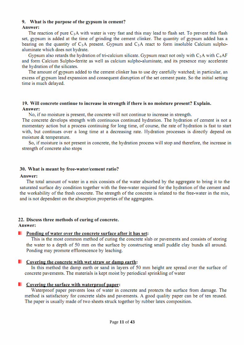
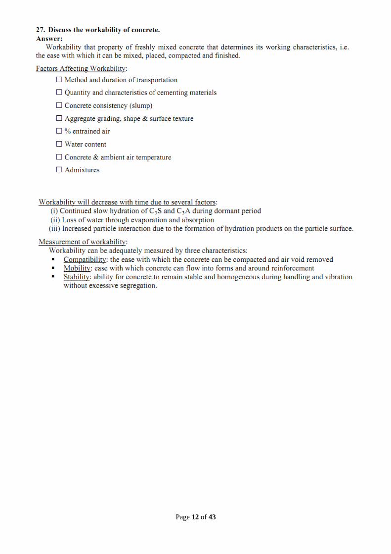
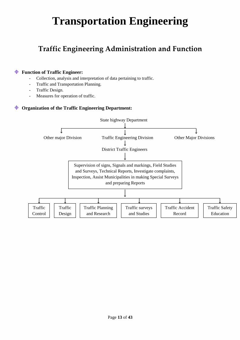
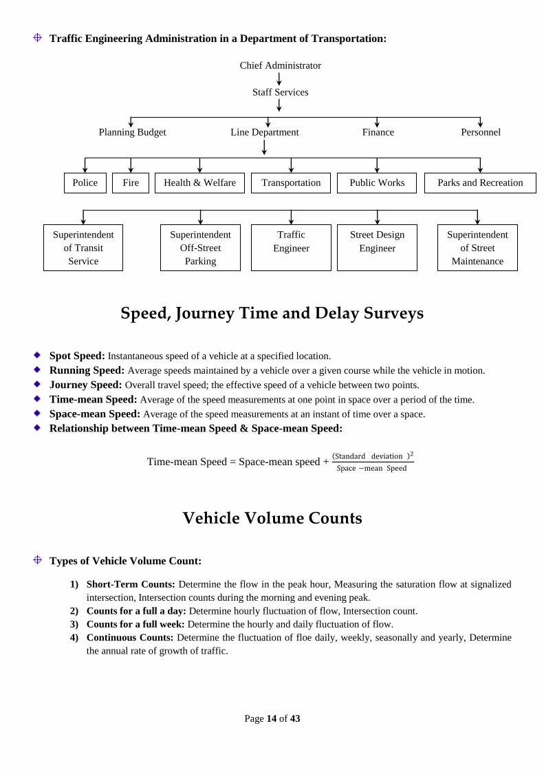
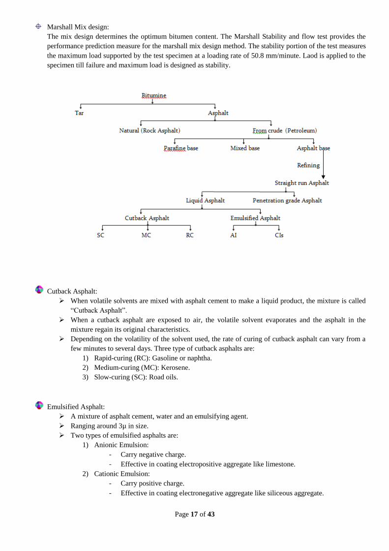
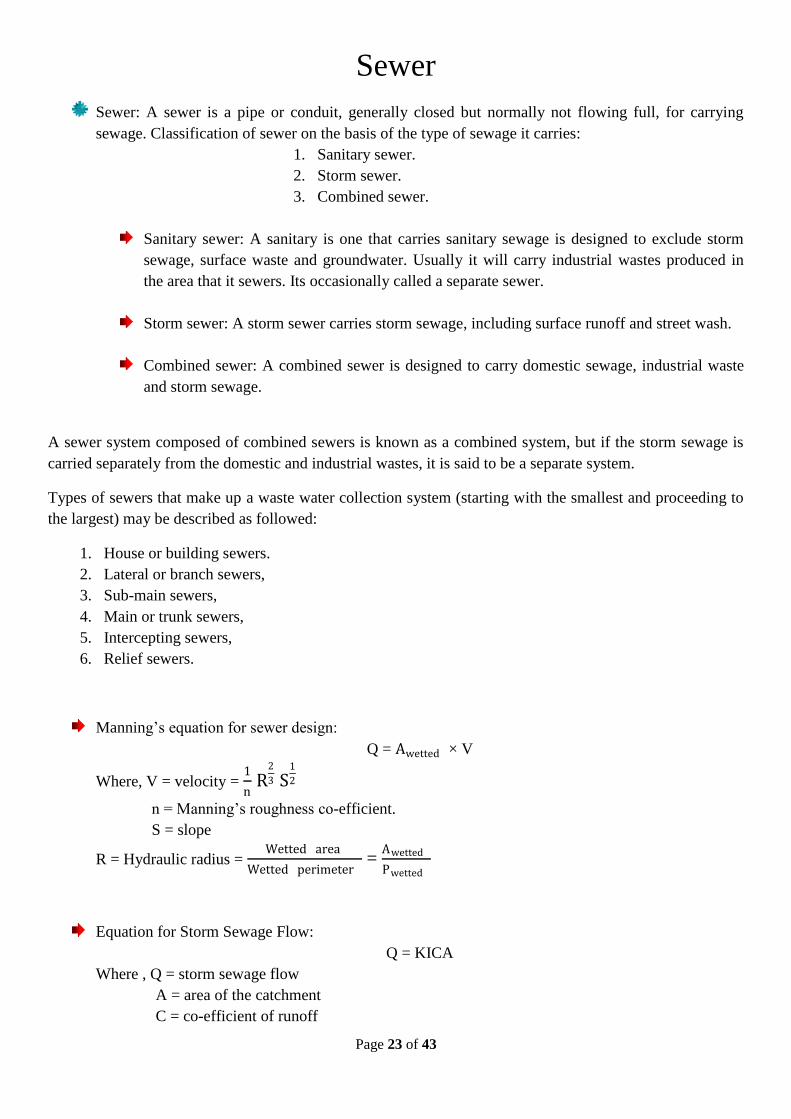
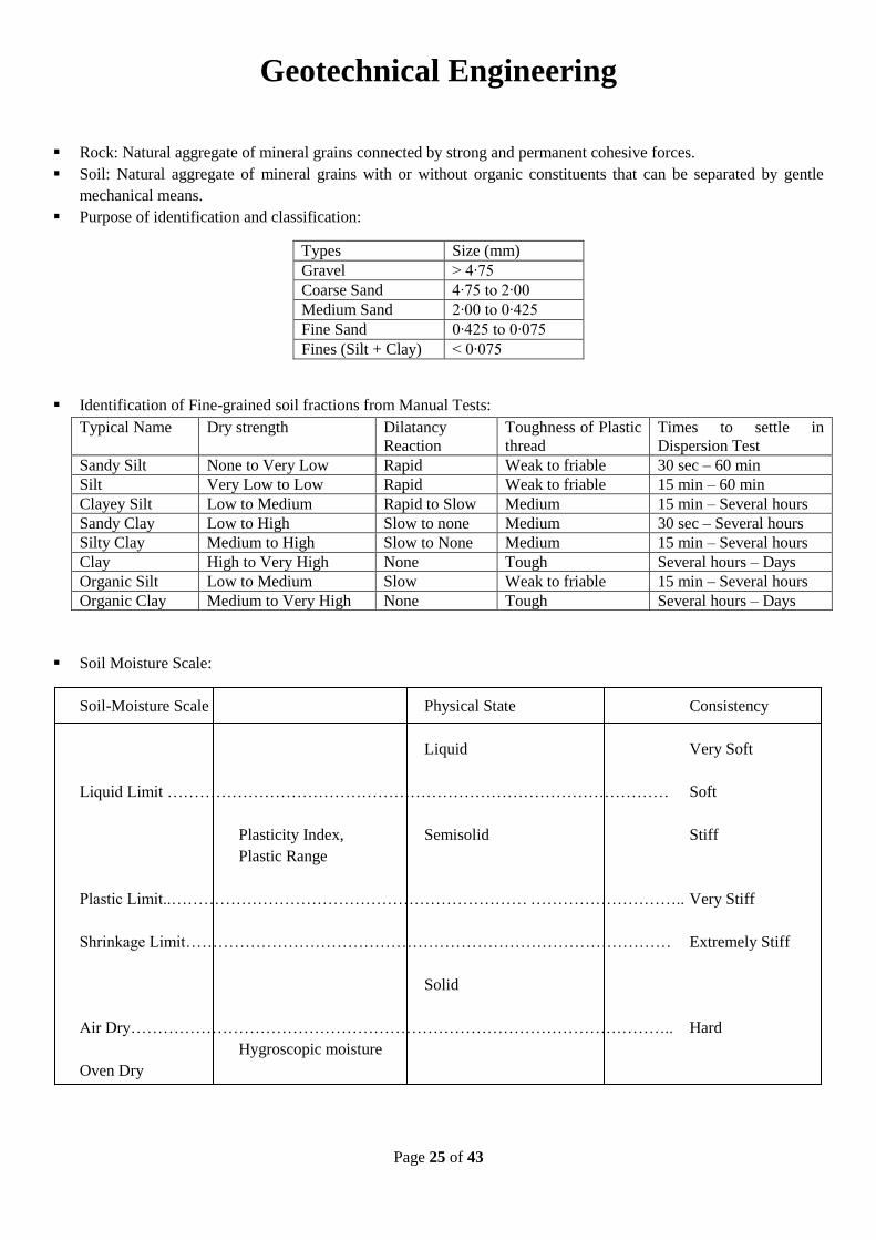
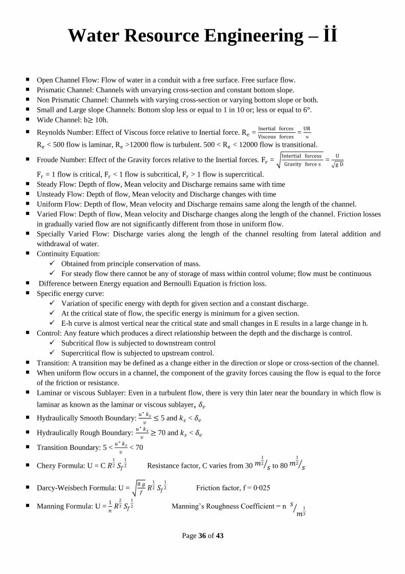
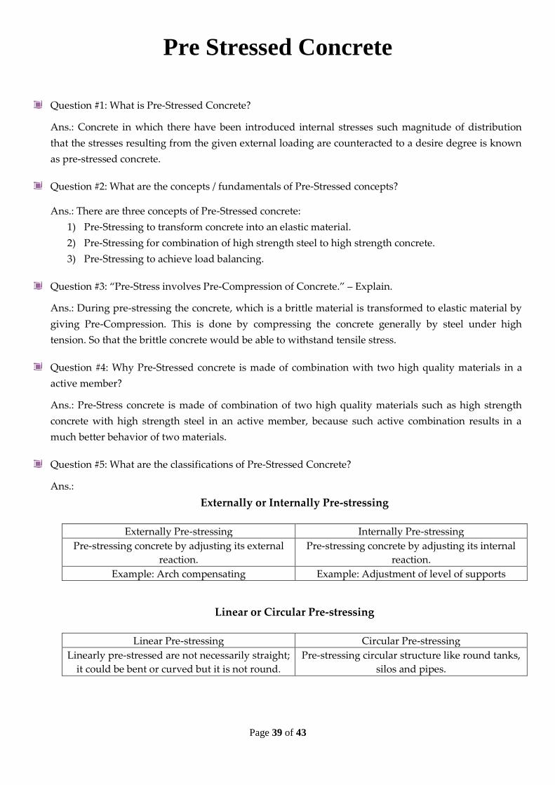
Related Documents