AD-A266 654 AEL/N88-94/PH II/93-1 N00024-90-C-4538 As Amended U1 SBIR TOPIC N88-94 I ! EVALUATION OF LAB TESTS I OF THE 3 INTERNAL REFORMATION OF I DESULFURIZED DIESEL FUEL U IN AN MCFC TEST STACK __ ~~~March 1993 ~ ~ '~~ Prepared by I ••.ARCTIC ENERGIES LTD 511 Heavitree Lane Severna Park Maryland 21146-1010 Tel 410-987-5454 Fax 410-987-7549 - -. Di.tribfi•-.,,,,, No 6

Welcome message from author
This document is posted to help you gain knowledge. Please leave a comment to let me know what you think about it! Share it to your friends and learn new things together.
Transcript

AD-A266 654AEL/N88-94/PH II/93-1
N00024-90-C-4538 As Amended
U1 SBIR TOPIC N88-94I! EVALUATION OF LAB TESTS
I OF THE
3 INTERNAL REFORMATION OF
I DESULFURIZED DIESEL FUEL
U IN AN MCFC TEST STACK
__ ~~~March 1993 ~ ~ '~~
Prepared by
I ••.ARCTIC ENERGIES LTD
511 Heavitree LaneSeverna ParkMaryland 21146-1010Tel 410-987-5454 Fax 410-987-7549
- -. Di.tribfi•-.,,,,,
No 6

PROJECT SUMMARY
Purpose of the Work
To demonstrate the internal reformation of diesel type fuel in a representative hightemperature molten carbonate or direct fuel cell (DFC) stack and to evaluate the results ofthe demonstration after at least 400 hours of operation.
Description of the Work Carried Out
Starting with the known capability of DFC stacks to internally reform natural gas (CH 4 ),the fuel vaporization and judicious breaking of the carbon bond in the more complex dieseltype fuel molecule (represented typically as C7H 14 ) was addressed. Free carbon couldpotentially load up the reformer passages and is thus to be avoided. Following carefultesting of numerous sub scale vaporization, fuel conditioning and reforming techniques,the most appropriate thermochemical means was derived by the AEL test subcontractorEnergy Research Corporation (ERC). It consists of a combined fuel vaporizer andadiabatic fuel conditioner column which, in effect, creates synthesized CH4 moleculesfrom the heavier hydrocarbon and then steam reforms the synthesis gas in the plate typereformer within the stack using the heat from the fuel cell stack.
The demonstration was successfully carried out in August 1992 for 400 hours under theNavy contract plus an additional 200 hours under a contract from the Electric PowerResearch Institute (EPRI). The equipment was then to be dismantled and the internalcharacteristics of the reformer and the DFC test stack analyzed and evaluated to determinewhether any life-limiting phenomena had occurred.
Findings and Results
The small scale system has worked. The fuel was vaporized, reformed andelectrochemically reacted to produce DC electricity and fresh water for the contracted 600hour test. No degradation of the performance was noted during the 600 hours. Thedismantled reformer plate and stack cells showed no carbon buildup.
Potential Application of the Effort
The successful demonstration of the internal reformation of diesel type fuel in a DFC stackat a small laboratory scale now defines the need to scale up the test to at least a 10 kWpower level using a stack of a commercial cross section of at least 2 ft x 2 ft. This hasbeen proposed to the Navy, using an existing DFC stack owned by the Department ofEnergy (DOE) and a test setup owned by EPRI, both located at ERC in Danbury, CN.The Navy has agreed to supply, as government furnished material (GFM), an amount ofdesulfurized diesel fuel sufficient for such a 400 hour test.
Fuel cell propulsion for ships will be very energy conversion efficient, will produce clean,quiet power with virtually no maintenance, will produce potable water and high qualitywaste heat. They will be rapidly changed-out because of the one-sided-fit modularapproach used in the design.
Sm,•mmmmmm mum m II I i II

II
SIGN OFF FOR THE SBIR TOPIC N88-94 PHASE II FINALI REPORT
Contract N00024-90-C-453 8
IContractor's Principal Investigator Sin Off On Report Contents
1. Pursuant to DD1423 A003 Technical Data Rights Claimed:
No technical data rights are claimed under this laboratory testand evaluation contract.
2. Pursuant to DD1423 A004 Computer Software Product:
No software products were developed under this laboratory test and3 evaluation contract.
3. Pursuant to DD1423 A006 System/Segment Specification:
3 No hardware system was to be delivered under the laboratory testand evaluation contract so no specification is applicable.
4. Pursuant to DD1423 A010 and A01 1 Product Drawings and Associated Lists:
No hardware product was to be delivered under this laboratory* test and evaluation contract.
5. Pursuant to DD1423 A012 Report of Inventions and Disclosure:
Two inventions/patentable disclosures were made by the AEL specialtest subcontractor ERC under this laboratory test and evaluationcontract. Executed Form 882's have been filed with NAVSEA.I 3.
William H. Kumm PI and President of Arctic Energies Ltd.(AEL) DateAccesion For
NTIS CRA&I
DTIC TAB L1DTW ;;j',c--, Unannounced El
Justification
By ......... . . .... ...................
Distribution /
Availability CodesAvail and/or
Dist Special
tt.I ,9I

U
I TABLE OF CONTENTS
* Page
PROJECT SUM M ARY .................................................................................................... i
APPROVAL SIGN OFF FOR THE SBIR TOPIC N88-94 PHASE IIFINAL REPORT ............................................................................................................. ii
Section
1. INTRODUCTION ................................................ I...1.1 Summary ....................................................................................................... 11.2 Conclusion ................................................ 1
2. DETAILED DESCRIPTION OF W ORK .............................................................. 32.1 Scope........................................................................................................32.2 Technical Background ................................................................................... 32.3 Test Article D escription ................................................................................. 6
2.3.1 Fuel ........................................................................................................ 62.3.2 Fuel Cell Stack ........................................................................................ 92.3.3 Reforming Unit (RU) Plate ...................................................................... 9
2.3.4 Vaporizer/Preconverter ........................................................................... 92.4 System Arrangem ent ........................................................................................... 112.5 Operating Procedure ........................................................................................... 11
2.5.1 Fuel Cell Stack Conditioning .................................................................. 112.5.2 Preconverter Conditioning .................................................................... 152.5.3 System Operation ................................................................................. 15
2.6 Results ......................................................................................................... 152.7 Ancillary Tests .............................................................................................. 15
2.7.1 Carbon Form ation .................................................................................. 152.8 Conclusions and Recommendations From Tests............................................... 18
2.8.1 Recomm endations .................................................................................. 18
I 3. APPENDICES ..............................................................................................................3.1 Sample Test Data Sheet ..........................................................................................3 .2 Test D ata Summary ................................................................................................3.3 DF•C Energy Balance ..............................................................................................3.4 Preconverter Energy Balance ..................................................................................
II
I iii

I
I LIST OF FIGURESE igu e ... ....... ............................ . . .......................................................................... P n e
11 DFC STACK ASSEMBLY ................................................................. 42 DIRECT FUEL CELL OPERATING PRINCIPLE....................................... 53 DFC SYSTEM CONCEPT .................................................................................. 74 VAPORIZER AND PRECONVERTER............................................................... 105 DFC DEMONSTRATION TEST ARRANGEMENT................................................ 12
S6 EQUIPM ENT SETUP ..................................................................... 13...........................7 SCHEMATIC OF TEST FACILITY ARRANGEMENT ................................ 148 NAVSEAIEPRI DEC DEMONSTRATION.............................................. 169 STACK PERFORMANCE WITH SRG (H20)
AND EXXSOLD110OFUEL............................................................... 17
LIST OF TABLES
Table ........................................................................................ Page
1 PROPERTIES OF EXXSOL D 110 ....................................................................... 8
II
IIII
!i

I
I 1. INTRODUCTION
1.1 Summary
The purpose of the contracted work was to demonstrate the internal reformation of dieseltype fuel in a representative high temperature molten carbonate or direct fuel cell (DFC)stack and to evaluate the results of the demonstration after at least 400 hours of operation.
Starting with the known capability of DFC stacks to internally reform natural gas (CH 4 ),the fuel vaporization and judicious breaking of the carbon bond in the more complex dieseltype fuel molecule (represented typically as C7H 14 ) was addressed. Free carbon couldpotentially load up the reformer passages and is thus to be avoided. Following carefultesting of numerous sub scale vaporization, fuel conditioning and reforming techniques,the most appropriate thermochemical means was derived by the AEL test subcontractorEnergy Research Corporation (ERC). It consists of a combined fuel vaporizer andadiabatic fuel conditioner column which, in effect, creates synthesized CH 4 moleculesfrom the heavier hydrocarbon and then steam reforms the synthesis gas in the plate typereformer within the stack using the heat from the fuel cell stack.
The demonstration was successfully carried out in August 1992 for 400 hours under theNavy contract plus an additional 200 hours under a contract from the Electric PowerResearch Institute (EPRI). The equipment was then to be dismantled and the internalcharacteristics of the reformer and the DFC test stack analyzed and evaluated to determinewhether any life-limiting phenomena had occurred. The small scale system test work hasbeen successful. The fuel was vaporized, reformed and electrochemically reacted toproduce DC electricity and fresh water for the contracted 600 hour test. No degradationof the performance was noted during the 600 hours. The dismantled reformer plate andstack cells showed no carbon buildup.
I The EPRI was pleased with the results of the work and we trust the Navy is also. TheSBIR Program has been successful in Phases I and II and AEL looks forward to Phase III
* and beyond.
1.2 Conclusion
The successful demonstration of the internal reformation of diesel type fuel in a DFC stackat a small laboratory scale now defines the need to scale up the test to at least a 10 kWpower level using a stack of a commercial cross section of at least 2 ft x 2 ft. This hasbeen proposed to the Navy, using an existing DFC stack owned by the Department ofEnergy (DOE) and a test setup owned by EPRI, both located at ERC in Danbury, CN.The Navy has agreed to supply, as government furnished material (GFM), an amount ofdesulfurized diesel fuel sufficient for such as 400 hour test.I
I
I 1 iiI II

I
I Once the 10 kW power level testing has been completed and a preliminary design task todefine the physical configuration of roughly 6 ft tall "half height" 60 kW DFC stackmodule is completed, a full scale naval power plant can be designed. The DFC technologyfrom which this design is derived is that of the on-land outdoor electric utilityconfiguration. These natural gas fueled utility units are currently rated at 120 kW in a 2 ftx 3 ft cross section 12 ft tall stack. No utility funded effort is currently underway toreduce weight or volume. All of the utility-oriented effort is devoted to reducing price perkW installed and to reducing the fuel rate or heat rate.
I The naval or maritime type 60 kW stacks will have a one-sided-fit with all manifolds andservice connections brought out through the bottom of the replaceable modules. Fuel cellpropelled small ships can then be designed and built using these modules based on DFCstacks with a 2 ft x 3 ft (6 ft2) cross sectional area. Subsequent higher power systems willbe based on 16 ft2 (4 ft x 4 ft) stack cells with a correspondingly higher power rating ofthe order of 160 kW per 6 ft tall modules.
The above description of a commercialization path assumes no parallel funded effort toreduce DFC weight and volume per kW. Adequate design and manufacturingexpenditures on that performance improvement path will then permit reductions of theorder of 30% in each of these two characteristics of DFCs.
Cooperation between the Navy and the civil sector agencies which operate ships, as wellas with the private sector ship owners, will accelerate the introduction of fuel cellpropulsion for ships of all kinds.
IIUIIIIII 2

I
2. DETAILED DESCRIPTION OF WORK
* 2.1 Scope
For a number of non-utility Direct Fuel Cell (DFC) applications, liquid fuels ratherthan natural gas are the fuels of interest. For naval applications, the fuel cell powerplants need to be operated with diesel fuel. While much effort has been expendedin the demonstration of efficiency and endurance of DFCs powered by natural gas,operating experience with diesel fuel is lacking. A project was therefore carriedout under the sponsorship of NAVSEA to build and operate a DFC system for400-hours on sulfur-free diesel or equivalent fuel in order to demonstrate thefeasibility of running DFC power plants with diesel-type and other logistic liquidfuels. A further 200-hours of testing were sponsored by the Electric PowerResearch Corporation (EPRI). The demonstration was performed successfully byEnergy Research Corporation (ERC) under subcontract to Arctic Energies Ltd.(AEL). The two companies have been collaborating toward development ofapplications for the DFC technology based on logistic liquid fuels in the defenseand remote polar power areas. This report describes the test article andsummarizes the result of the liquid fuel DFC system demonstration test.
2.2 Technical Background
Fuel cells convert chemical energy of fuel directly into electricity without anyintermediate conversion to heat and mechanical energy. Direct carbonate fuel cells(DFCs) are capable of reforming hydrocarbon fuels internally without the use ofexternal reformers. Therefore, they are more efficient and simpler than other typesof fuel cells. Direct fuel cells are currently under development for use with naturalgas fuel as well as coal derived gaseous fuels. This gas fueled work is sponsoredmainly by the Department of Energy, the Electric Power Research Institute, and agroup of municipal and private utility companies.
ERC's carbonate fuel cell stacks have been developed for utility power generationand incorporate internal reforming plate units which allow direct conversion ofnatural gas into hydrogen which is used in the fuel cell anodes for electrochemical3 power generation. Reforming plates are incorporated in the fuel cell stack andsupplied with the gaseous fuel from a common header as illustrated in Figure 1.Internal reforming reduces equipment complexity by eliminating the need forexternal reforming equipment, increases system efficiency by utilizing the stackwaste heat for reforming, and reduces the cooling requirement for the stack.
Figure 2 illustrates the chemical reactions which occur in the direct fuel cell (DFC)stack. The main reaction in the stack internal reforming units is conversion ofmethane to hydrogen. Hydrogen is then consumed in the power producingreaction in the electrochemical cells. The roughly 5% hydrogen remaining in theanode tailgas is combusted with excess air to provide oxygen and carbon dioxide.I
I 3 i II I

IENERGY RESEARCH CORPATIONI
II
I REFORMING UNITE
* /DIELECTRIC SEPARATOR
I ICELL PACKAGES
i ~FIGURE ,1 DEC STACK ASSEMBLY
IIII mmmmm

1I
ENERGY RESEARCH CORPORATION
IIII
FUEL CH 4 "+"H2 0 ±CO+"-3H2 0
S--- E
3 H2+CO;_H 2o +C02+25
A
H
C03 R
II
1 FIGURE 2 DIRECT FUEL CELL OPERATING PRINCIPLE
II
I 51A
-- --• ,, Ii i a I I IIT
I
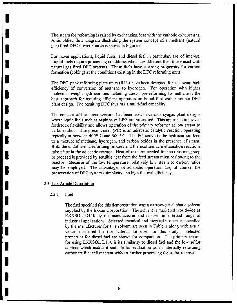
I The steam for reforming is raised by exchanging heat with the cathode exhaust gas.A simplified flow diagram illustrating the system concept of a methane (naturalgas) fired DFC power source is shown in Figure 3.
For navai applications, liquid fuels, and diesel fuel in particular, are of interest.Liquid fuels require processing conditions which are different than those used withnatural gas fired DFC systems. These fuels have a strong propensity for carbonformation (coking) at the conditions existing in the DFC reforming units.
I The DFC stack reforming plate units (RUs) have been designed for achieving highefficiency of conversion of methane to hydrogen. For operation with highermolecular weight hydrocarbons including diesel, pre-reforming to methane is thebest approach for assuring efficient operation on liquid fuel with a simple DFCplant design. The resulting DFC thus has a multi-fuel capability.
The concept of fuel preconversion has been used in various syngas plant designswhere liquid fuels such as naphtha or LPG are processed. This approach improvesfeedstock flexibility and allows operation of the primary reformer at low steam tocarbon ratios. The preconverter (PC) is an adiabatic catalytic reaction operatingtypically at between 4000 C and 5000 C. The PC converts the hydrocarbon feedto a mixture of methane, hydrogen, and carbon oxides in the presence of steam.Both the endothermic reforming process and the exothermic methanation reactionstake place in the adiabatic reactor. Heat of reaction needed for the reforming stepto proceed is provided by sensible heat from the feed stream mixture flowing to thereactor. Because of the low temperature, relatively low steam to carbon ratiosmay be employed. The advantages of adiabatic operation are, of course, thepreservation of DFC system's simplicity and high thermal efficiency.
2.3 Test Article Description
2.3.1 Fuel
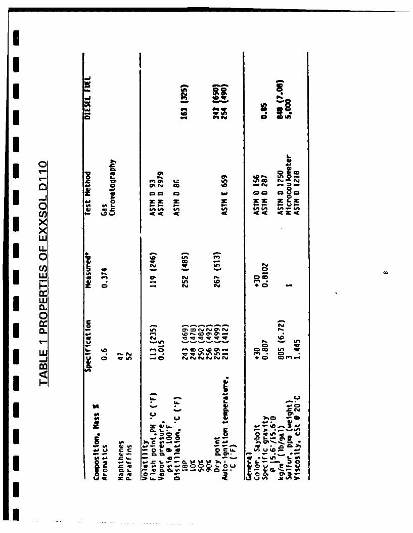
I The fuel specified for this demonstration was a narrow-cut aliphatic solventsupplied by the Exxon Corporation. The solvent is marketed worldwide asEXXSOL Dl0 by the manufacturer and is used in a broad range ofindustrial applications. Selected chemical and physical properties specifiedby the manufacturer for this solvent are seen in Table I along with actualvalues measured for the material lot used for this study. Selectedproperties for diesel fuel are shown for comparison. The primary reasonfor using EXXSOL DI 10 is its similarity to diesel fuel and the low sulfurcontent which makes it suitable for evaluation as an internally reformingcarbonate fuel cell reactant without further processing for sulfur removal.
!6

U F
* .0
IU U)
LLwn L0
I Y 11w 0"
uIgI LAS
==On
Ij
-a ID iiIo
so- Vi C ."0 0%"G Da
0C* "i& C3 CU
4iA~ 60 .#- 0- #. - t.- 0- 1- % I0 to % " Ln & m A-W
'0 LM "
LU Cv- C- C
0Ln -r -o -v VQ-~- 0% N
j CD 4W1n WewB- wc
.C; 0 0 tv.O0 .0 $-i'
4A 4. o" -P': 0
do u c c -.... s.( d 1
6 -A do~~ 0-o~ i -6
as &Ad d-acDC OCiClL.0L U E'&. u06~ ~ ~ L. -6C A k SQ40t
I.c L yziIAd jv O i

I
A carbon-hydrogen analysis for the test fuel showed 86.3% carbon and14.1% hydrogen, which indicates an empirical formula of CH 1 .9 5 . Bycomparison, th, heaviest diesel fuel, DF-2 has the empirical formulaCH 1.7 . EXXSOL Dl10 may be expected to have fuel processingrequirements somewhere between those of diesel oil and naphtha, whichhas an empirical formula CH 2 2 .
2.3.2 Fuel Cell Stack
The carbonate fuel cell stack used for the 400-hour demonstrationconsisted of 5 cells each measuring 7 in. x 7 in. overall. The activeelectrode area of the cells was 0.25 ft2 . The stack was assembled withendplate heaters and was supported in a pneumatic compression rig.
2.3.3 Reforming Unit (RU) Plate
The reforming unit (RU) plate was scaled to reform fuel for the 5-cell stackat nominal operating conditions of 150 mA/cm2 (35A), and had overalldimensions of 7 in. x 7 in. The standard nickel reforming catalyst used inall of ERC's direct fuel cell stacks was employed.
The internal reforming unit was assembled unit was assembled in a separatesupport rig which was equipped with separate heaters and temperatureregulator. This assembly arrangement was chosen over a single assemblycomprising the fuel cell stack and the reforming plate as a precautionagainst the loss of the fuel cell stack in case of a test facility upset resultingin damage to the reforming unit.
2.3.4 Vaporizer/Preconverter
Preliminary testing for ability to directly reform the EXXSOL D 110 fuel inthe reforming unit produced heavy carbon deposition. Increasing the ratioof steam to carbon ratio to values as high as S/C = 10 did not entirelyeliminate carbon formation. An auxiliary fuel converter reactor wastherefore constructed and installed ahead of the reforming unit. Thisreactor operates at 400-4500 C and converts the higher hydrocarbons tomethane, hydrogen and carbon dioxide. The principal reactions in thepreconverter are endothermic reforming to CO and H2 followed byexothermic methanation to CH 4 and CO 2 . A two-pass reactor tube designwas utilized as shown in Figure 4 to enhance heat transfer within thecatalyst bed. Because of the small scale of the equipment, clamshellheaters were used to maintain the desired reactor bed temperature of 400-4500.
I!9

IENERGY RESEARCH CORPORATION
EXXSOL INLET 11,2 INLET
I
i'VAPORIZER
Ie _ HEATER
II 'P To
TC2 TC I
TOCONDENSERI .m
' CATALYST BED
REACTOR_
II HEATER 5 TC9
I__ - , TC4
FIGURE 4 VAPORIZER AND PRECONVERTER
III i

I
The preconverter column employed concentric tubes. The outer tube had an ODof 2 inches and the inner tube had an OD of 3/4 inches. The wall thickness of bothtubes was 0.035 inches. The nickel catalyst column of 30 inches, of which 27inches were packed with catalyst. The rest of the column (ends) contained packingmaterial. The catalyst weight was approximately 1.2 kg.
I The vaporizer had an O.D. of 2 inches and a wall thickness of 0.035 inches. It wasfilled with stainless steel wool for a packed height of about 26 inches. Waterentered at the top while EXXSOL D 110 liquid inlet was at roughly midpoint of thevertical vaporizer column. External clamshell heaters were used to supply heat.
I 2.4 System Arrangement
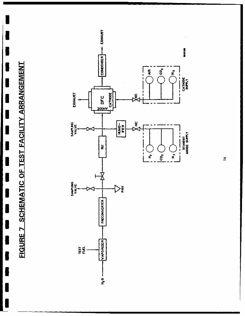
The arrangement of the principal components used for the 400-hour demonstrationrun is shown in Figure 5. The preconverter was built as an integral unit with thevaporizer. Fuel and water were pumped to the top of the downflow vaporizercolumn. The vaporized fuel and mixture passed through the preconverter reactorto the reforming unit and the anode of the fuel cell stack. Figure 6 shows aphotograph of the equipment setup. The vaporizer/preconverter is larger thanrequired for the small scale Navy and EPRI test conducted. It was built to supplyreforming plates for a 2 kW stack to be tested later.
The overall arrangement of the test facility is shown schematically in Figure 7. Thestack was set up to allow operation with both hydrogen fuel and EXXSOL D 110,the test fuel. Traditional anode and cathode gas compositions were used duringsystem start and stack performance characterization testing. A standby gas systemand auxiliary power source were installed to provide orderly system shutdown incase of test equipment failure or loss of mains power.
2.5 Operating Procedure
I 2.5.1 Fuel Cell Stack Conditioning
The fuel cell stack was operated on simulated reformed gas (SRG) fuel fora period of about 900 hours before the testing with EXXSOL D110commenced. The SRG fuel composition during this period of stack
* operation was:
H2 73.0%CO 18.0%H2 0 9.0%I
I,, iII !I 11

UjU
aaID
0
cc sf*cc
01.m
Iwo.
coo
ooCY1
cc cc
Uc.L
0 w
co w co CII 0
z U)8C.) 0I
LU wILLIUc

I Ni
m I- l Ic
ILI
I w
Ij w
CDO
*I S
x 4c
cnn LLJ~~~ lo"-"JILL
0
0>
cI Iww
I w
CD 0
I i
I_>

I The stack cathode gas used was based on simulated SRG burner recyclestream and had the composition:
I 02 9.7%C02 13.8%N2 76.5%
The initial stack operating period served to stabilize stack output voltage atthe nominal stack current of 35 amperes (150 amperes/square foot) and toestablish any rate of stack voltage change with time on SRG fuel. Thisestablished the baseline stack voltage for evaluation of the effect ofEXXSOL D1 10 fuel on output voltage.
2.5.2 Preconverter Conditioning
The preconverter was operated for a short time (less than 100 hours) toestablish control parameters for steady state operation at the conditions tobe used during the test run. Performance stability was demonstrated byperiodically verifying product gas composition stability and by monitoringinternal reactor temperatures.
2.5.3 System Operation
I The demonstration run with EXXSOL D1 10 fuel commenced directly afteroperation of the stack with SRG without system shutdown. Following abrief period (5 minutes) of operation with both SRG and EXXSOL D110flowing, the SRG flow was shut off. Operation of the system thancontinued on a 24 hour/day basis with EXXSOL Dl10 fuel for a total of630 hours. Simulated reformer gas was introduced into the anode streamand the liquid fuel and water flow to the system were turned off. The testwas interrupted once for about 100 hours to replace a defectivetemperature controller. During this 100 hour period the stack continued tooperate with SRG fuel.
The temperature of key test equipment and of the process streams weremonitored continuously and recorded periodically on data sheets.Appendix 1 shows an example of the recorded data. In addition to themanually recorded data, a continuous record was obtained of key processparameters by the use of strip chart recorders. The continuously recordedparameters were stack voltage, stack current and stack temperature.
2.6
I For the duration of the entire test run, all monitored parameters remained withinnormal operating range. The reformate composition exiting the RU plate also
I15 II

*25 'uoi4!sodwoo SD9 Ind4nQ nAd0 0 0 0 0 0 0 0 0 0
(D 0 qd 0(0
a))
z 000 -0
LU C PU). 0
> CL 0
00
z) 0
* j C-)
> 0
00 Q)0lwx I 1 1 I I 11 00
0 t) 0 It) 00 L( (
I ~ ~ V LA- (N(r6I* A 1~D4O 1Z.4S 34 ooI
ItI
D 0I. 0LLO
x -0x 0
N 0*) -0U
0 t~- LO)
CC -C
0 C0
I LO00
z T
0O
I~~~ 0 00000
W ~ ~ ~ L L() n - ~
A 'GbDIlOA >pDDJS

I
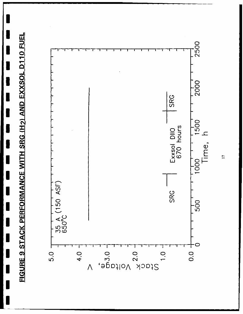
remained constant during the demonstration run as may be seen from thecomposition-time plot presented in Figure 8. This figure also shows a plot of thestack voltage while operating with the EXXSOL D1 10 fuel.
2.7 Ancillary Tests
As can be seen from the voltage-time plot in Figure 9 the stack output voltage wasnot affected markedly by switching from SRG to EXXSOL Dl10. This is, ofcourse, an expected results based on the demonstrated conversion of the fuel tohydrogen in the reforming plate. The reformate composition along with otheroperating parameters during the test run is presented in Table A-I in the Appendix.
2.7.1 Carbon Formation
Disassembly of the RU plate showed no evidence of carbon formation.Likewise, teardown inspection of the fuel cell stack showed no carboneither in the fuel manifold or in the cells themselves.
2.8 Conclusions And Recommendations From Tests
The results of this demonstration test shows that Direct Fuel Cell power systemscan operate with a low-sulfur, diesel-like fuel. The performance level does notmarkedly differ from performance with reformed natural gas fuel. Operating witha carbon/steam ratio of 4, an adiabatic preconverter is effective in precludingcarbon formation both within the RU and within the cell stack.
Concerning additional testing needed, ERC feels that some development work onthe preconverter reactor will be needed to come up with the most effectiveconfiguration for adiabatic operation without objectionable carbon depositionrates. Similarly, a better vaporizer design is needed.
Regarding conclusions, ERC also feels that this is a very attractive system and thata demonstration at a 10 kW level should be launched. The weight and volume ofthe preconverter probably will not be very significant when compared with the restof the plant. If an external preconverter is needed as it now appears to be the case,its weight will probably contribute less than 5% of the total power plant systemweight.
2.8.1 AEL Recommendations
Discussion have continued with Navy technical staff about future scale upof the tests to 10 kW using a Government owned DFC stack. ThisPhase HI effort would also be carried out at ERC using an EPRI ownedtest setup. Cost sharing has already been obtained from third partyagencies for this phase of the scale up work.
I18I

II
NAVSEA has already agreed to provide sulfur-free diesel fuel for a 400hour lab test. The remaining issue, as of March 1993, is to provide thefunding for this work.
Beyond the 10 kW lab test will be a 60 kW stack for use in "field tests" inabout 2 years. Beyond a single 60 kW power plant the power levelbecomes large enough to drive a small ship. This will be followed by largerships as the power plant sizes are steadily increased. Fuel cell propulsionfor ships will progress at essentially the rate that funding is applied to theinitiative. The issue is no longer "whether it will work" it is now "howsoon can it be done?"
AEL is eager and willing to proceed. We have also been activelyencouraging commercial ship owners to support the work and this businessdevelopment process continues.
IIIIIIIIIII
i i. i i I [] I l9

Clo-Jwi
LU
0L 0u
SLLU- LU mCl5
x / (I )cc* 0 zi
*n di'__D 0 LU c
I-% 1 - C . -/
0 Lo
>L LLIui
0 00 0~ L .
k o) > ZL LL U 0.
c c > -LUC1
-JU -> nc L
cc LU
LLJ 0. Icn
0, ccL 0 L 0 wLu)0 o
Uf L&x 00, cn z
Ox Cl) -J Waxw I- >
_L z j L ZNI 00
0 0 0

II 3. APPENDICES
IIIIIIIUIII
III
I!2

I ENERGY RESEARCH CORPORATION
IIIIII* APPENDIXi1
SAMPLE DATA SHEET
IIIIIIIII
I A.I1-1
I

itNLkbi xoLmLKj LLJWPWTJON
IC
Nr
I .0
40 1%d-A U
1.9 ýali~a~
Ii. Wi. V%.* ~l1 J ~ .~
J~ Nt_)JI I U ELa) axLx1g I
II
CII4
CLCc. qx' azcc
0.ICIII
A. 1-2

0) 4 4 4 4) vV 4 $
Li A dM 1:4)~144 4)6 )4 4 u f . 411.4 E-4 1-4 1-4 E- E-4 A4 $4 41 r'4
0 4 04 014 4"4 1 0 0) .-4 0
%444%444%4%40"" E-4 E4 E u-4-4 4 0 1000
4)C14t o o 0 4 1A 410 41 004141c 4 la t 0 0 4
0-
V4 41 9-4 qw In %DfGo O
fu4 .. 4u 94 M V 0
::o -i 0 1 0
eLi ci
AO - 01 V4 4414 m
41 0 H 0 H0 c 0
c Od 0 41 4 F-4-r4~~0 Li W 4 1O
aw~~4 0 j 0
L)$40 41 0 O H Vi OCJ
44mC0C 9X 414V
$4E
Laii01
V~~~ U~ uD ff9 u0 r4 .,. j, c. 13
0
A. 1-3

ENERGY RESEARCH CORPORATION
IIIIII,I APPENDIX 2
I DATA SUMMARY
IIIIIIII
I

c C %J Cý -a .C- 0ý rn L
"0-W
C' -W
rJr~
0%ý kn fn 0D Ln P% ma, f-L Ao .l w C; to toCi; '
r- ~ 0 - l jr
0%~~ n 11 -n %9 U,
-W &n M nPS ~ P - - 0CD U~ C o n i
r, CO -- - - - - ---a -' en- -
as %V %n Ch In 0% CU P ZL 0
kn 0% %n WU LAnto coW - C; cl; 14 f. to11 to 0 * L
en en W- L c 11 % lý19 11
-o CD C4 - 1., run,
0 0% ~V- 1% 4T0 L
C4 C4J
C 20. in C
LAk- m% %.j LA L C.*0-i nto t
to U.n -- (D IS e LA
PS~~~~A 2-2- ~0 LAP

II
In -D - - - --- -6 -.
OD LA0
r ~- C'J LQLn.0 0 ,0r ~ r ~ .
fn IM cli 0 D 0 , Lb -
Io A:8 ' ~ L
- ~ L LAidu S C!J C) 9-I~- -i 03 8s . '
:9~~~
LA w ela
I (S~A. 2-3

ENERGY RESEARCH CORPORATION
UUIIIU
U APPENDIX 3
3DFC ENERGY BALANCE
U11I1IIIIA3-
I
IU
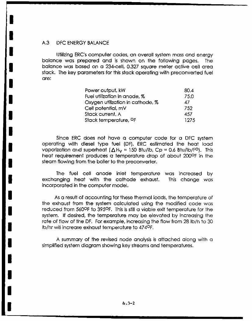
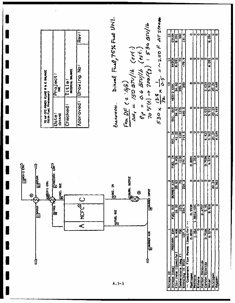
A.3 DFC ENERGY BALANCE
I ~Utilizing ERC's computer codes, an overall system mass and energybalance was prepared and is shown on the following pages. Thebalance was based on a 234-cell, 0.327 square meter active cell areastack. The key parameters for this stack operating with preconverted fuelare:
Power output, kW 80.4Fuel utilization in anode, % 75.0Oxygen utilization in cathode, % 47Cell potential, mV 752Stack current, A 457Stack temperature, OF 1275
ISince ERC does not have a computer code for a DFC system
operating with diesel type fuel (DF), ERC estimated the heat loadvaporization arid superheat (AHv = 150 Btu/lb, Cp = 0.6 Btu/Ib/FO). Thisheat requirement produces a temperature drop of about 200OF in thesteam flowing from the boiler to the preconverter.
The fuel cell anode inlet temperature was increased byexchanging heat with the cathode exhaust. This change wasincorporated in the computer model.
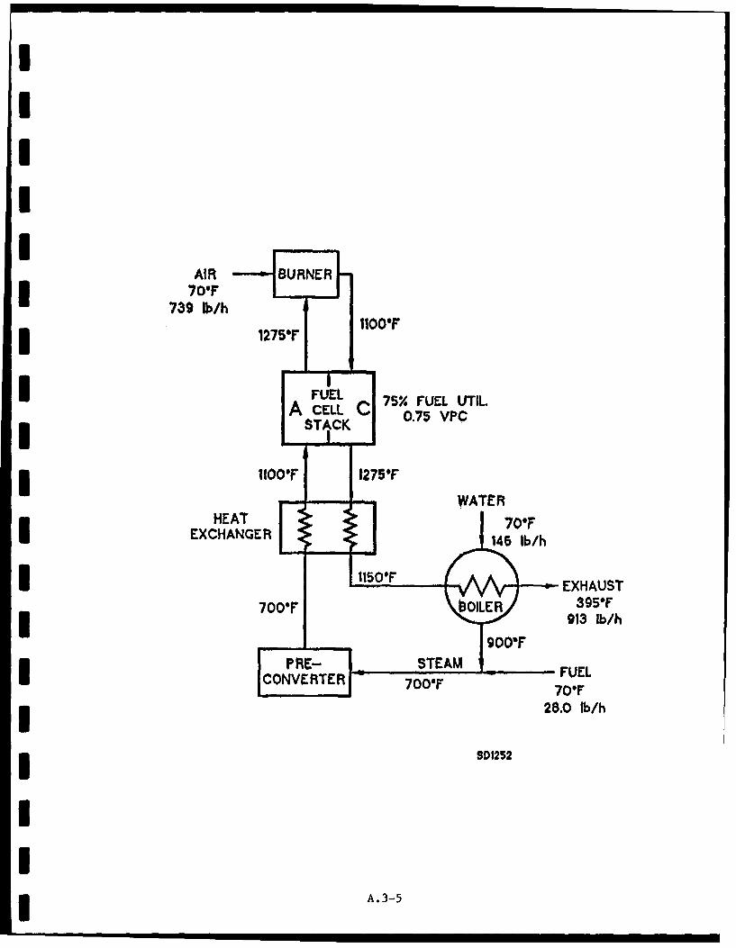
I As a result of accounting for these thermal loads, the temperature ofthe exhaust from the system calculated using the modified code wasreduced from 560OF to 395 0 F. This is still a viable exit temperature for thesystem. If desired, the temperature may be elevated by increasing therate of flow of the DF. For example, increasing the flow from 28 lb/h to 30lb/hr will increase exhaust temperature to 4740 F.
A summary of the revised node analysis is attached along with asimplified system diagram showing key streams and temperatures.
I
I A.-
I , I
Ig _s04 _ ooo- N'
* NI~tCL
w~~~~~C 0 0'4f~ ~I N
It r. N. QQ
2~0A. 3.-3

doo
L LI 0-
4- P
Ne0slc 000
MaV O., 000000;
"I A
-Ij
LaA. 3
AIR BURNER70'F
739 Iki/h
1275* 1100*F
IFUEL 75%0ULUIA CELL C 0.7 FUL TISTACK0.75 VPC
1F I 275 F W A
HEAT70FOEXCHANGER 16l/
I10* EXHAUST700*F OOR395*F
I 913 lb/b
PR-STEAM -FUELICONVEIRTER -7007 709F'3 28.0 tb/h
3 SD1252
I
Ii.-

I ENERGY RESEARCH CORPORPATION
IIII
I,
S~APPENDIX 4
PRECONVERTER THERMAL BALANCE
1
III
I A.4-1
I

ENERGY RESEARCH CORPORATION
A.4 THERMAL. BALANCE FOR PC
Preconversion of liquid fuels to methane and hydrogen is needed to prevent
coking in the reforming plates of the fuel cell stack. In order to retain the
simplicity and high efficiency of the DFC system, the preconverter (PC) unit
should be operating at essentially thermoneutral process conditions. An
adiabatic PC reactor requiring no thermal management can then be employed in the
DFC system between the vaporizer and the fuel cell stack.
The product gas composition at the thermoneutral operating point for the
* reactor can be readily estimated by utilizing a heat of combustion balance for
the reactants and products. The following values were used for the net heats of
* combustion:
Diesel Oil (CH,.O), 258,000 Btu/mol/n
Methane (CH4) 346,000 Btu/mol
Hydrogen (H,) 104,000 Btu/mol
The heat balance for the reaction
SCHI.$ + nH2O --- > (1-0.5n)CH, + (2n-l.l)H2 + 0.SnCO2
l shows that the reaction is slightly endothermic when n = 0.8 and slightly
exothermic when n = 0.7, as seen from the product heat values tabulated in Table
A.4-1. (Because CO concentration is less than 0.6%, its effect on the thermal
balance is small.) The preconverted fuel gas flowing to the stack will,
therefore, have a methane content of 40-50% on a dry basis.
III
I A.4-2
I

ENERGY RESEARCH CORPORATION
I TABLE A.4-1
PRECONVERTER HEAT BALANCE
Basis: 1 Ibmol of CH,., (13.8 lb, 18,700 Btu/lb)
CH1., + nH20 --- > (1-0.5n)CH, + (n-1.1)H, + 0.5nCO,
I n = 0.8 0.75 0.7Methane
mols 0.6 0.625 0.65Btu 207,600 216,250 224,900Vol % 40.0 44.6 50.0
I Hydrogen
mols 0.5 0.4 0.3Btu 52,000 41,600 31,200Vol % 33.3 28.6 23.1
IC0 mols 0.4 0.375 0.35Vol % 26.7 26.8 26.9
Total
mols 1.5 1.4 1.3Btu 259,600 257,850 256,100
Balance, Btu -1,600 +150 +1,900
,.-IIIIII
A.4- 3
I
Related Documents