MOD R11: Replacement Procedure ActCont ER 2-Way Gas with ESD 05-02-11 Actuator Control – Electric Remote 2-Way with ESD Valve Replacement Procedure on a Rotary Vane Actuator with a System using Power Gas

Welcome message from author
This document is posted to help you gain knowledge. Please leave a comment to let me know what you think about it! Share it to your friends and learn new things together.
Transcript
MOD R11: Replacement Procedure
ActCont ER 2-Way Gas with ESD 05-02-11
Actuator Control – Electric Remote 2-Way with ESD Valve Replacement Procedure on a Rotary Vane Actuator with a System using Power Gas

MOD R11: Replacement Procedure
ActCont ER 2-Way Gas with ESD
05-02-11
Page 1
The purpose of this procedure is to guide the replacement of an Actuator Control with standard features.
This procedure is to be used in conjunction with the following Maintenance and Service Manuals.
Shafer Poppet Block Control Maintenance and Service Manual Bulletin PBC-01102001
Shafer Hand Pump Maintenance and Service Manual Bulletin MHP-01102001
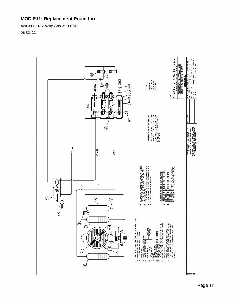
Schematic Diagram Fail Close – 8357-S
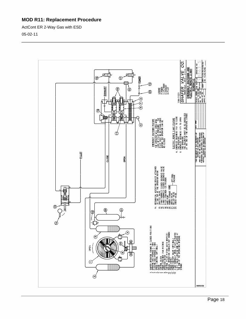
Fail Open – 8863-S
WARNING: 1. Turn power gas off (bleed down the power storage tank if applicable).
2. Drain oil out of the gas hydraulic tanks.
Remove the Old Control Box and Hand Pump 1. Remove the piping to the power port and exhaust port (if existing) of the old control block.
2. Remove the two tube lines (OPEN and CLOSE) running from the control block to the top of the gas hydraulic tanks.
3. Remove the tube line going from the power storage tank to the control block, if applicable.
4. Remove the tube lines going from the top of hand pump to the actuator. (Typically with older models, the hand pump will be mounted on the opposite side of the actuator as the control box.)
5. Remove the hand pump suction lines going from the gas hydraulic tanks to the bottom of the hand pump.
Figure 1: Typical Original Assembly

MOD R11: Replacement Procedure
ActCont ER 2-Way Gas with ESD
05-02-11
Page 2
6. This should complete the pipe/tube connections freeing the old control box and hand pump for removal. Remove the control box and hand pump. Set the old parts aside for reference.
7. Remove the Diffusers from the top of the gas hydraulic tanks and the drains from the bottom if applicable.
Note: Some gas hydraulic tanks may not have ¾” or larger NPT thread in the bottom and will not accept the new style drain assembly. In this case, new drain assemblies will not be included. On these models, the suction lines, for the hand pump, enter the side of the tanks near the bottom and the bottom port remains plugged.
Figure 2: Old Components Removed
8. Remove the fittings in the side of the actuator that were tubed to the OPEN and CLOSE lines from the old hand pump. Also, remove the plugs in the upper head on the control side. Clean the threads of the plugs, apply an appropriate pipe sealant and plug the side ports. (See Figure 2)

MOD R11: Replacement Procedure
ActCont ER 2-Way Gas with ESD
05-02-11
Page 3
Install the New Control Box, Limit Valve and Limit Switch Assy The new control box mounts to the same holes in the bracket on the gas hydraulic Tanks as the old one using 4" long standoffs. Look the new hardware over to enable identification of the parts.
1. Using 4 of the 8 mounting bolts and lock washers, install the four standoffs to the mounting bracket. Do not tighten the bolts. (See Figure 3)
2. With the other four mounting bolts and lock washers, install the new control box using the 9.5" x 11.25" hole pattern in the control box back plate. Leave the bolts finger tight.
3. Tighten the mounting bolts in the bracket and then tighten the bolts in the back plate.
Figure 3: Installing New Control
REDUCER/DRAIN ASSEMBLY
DIFFUSER ASSEMBLY
DIP STICK
NEW TUBE FITTINGS
MOUNTING BOLTS AND LOCK WASHERS
STANDOFFS
MOD R11: Replacement Procedure
ActCont ER 2-Way Gas with ESD
05-02-11
Page 4
4. Apply an appropriate pipe sealant and install the new Reducer/Drain Assembly in the bottom of the gas hydraulic tanks if applicable. (See Figure 3)
5. Assemble the dipsticks to the new Diffuser Assemblies. Apply an appropriate pipe sealant and install the Diffuser Assemblies in the top ports of the gas hydraulic tanks.
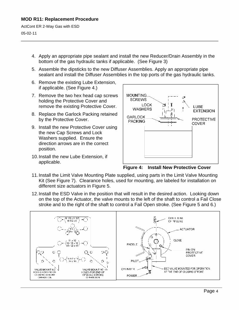
6. Remove the existing Lube Extension, if applicable. (See Figure 4.)
7. Remove the two hex head cap screws holding the Protective Cover and remove the existing Protective Cover.
8. Replace the Garlock Packing retained by the Protective Cover.
9. Install the new Protective Cover using the new Cap Screws and Lock Washers supplied. Ensure the direction arrows are in the correct position.
10. Install the new Lube Extension, if applicable.
Figure 4: Install New Protective Cover
11. Install the Limit Valve Mounting Plate supplied, using parts in the Limit Valve Mounting Kit (See Figure 7). Clearance holes, used for mounting, are labeled for installation on different size actuators in Figure 5.
12. Install the ESD Valve in the position that will result in the desired action. Looking down on the top of the Actuator, the valve mounts to the left of the shaft to control a Fail Close stroke and to the right of the shaft to control a Fail Open stroke. (See Figure 5 and 6.)
MOD R11: Replacement Procedure
ActCont ER 2-Way Gas with ESD
05-02-11
Page 5
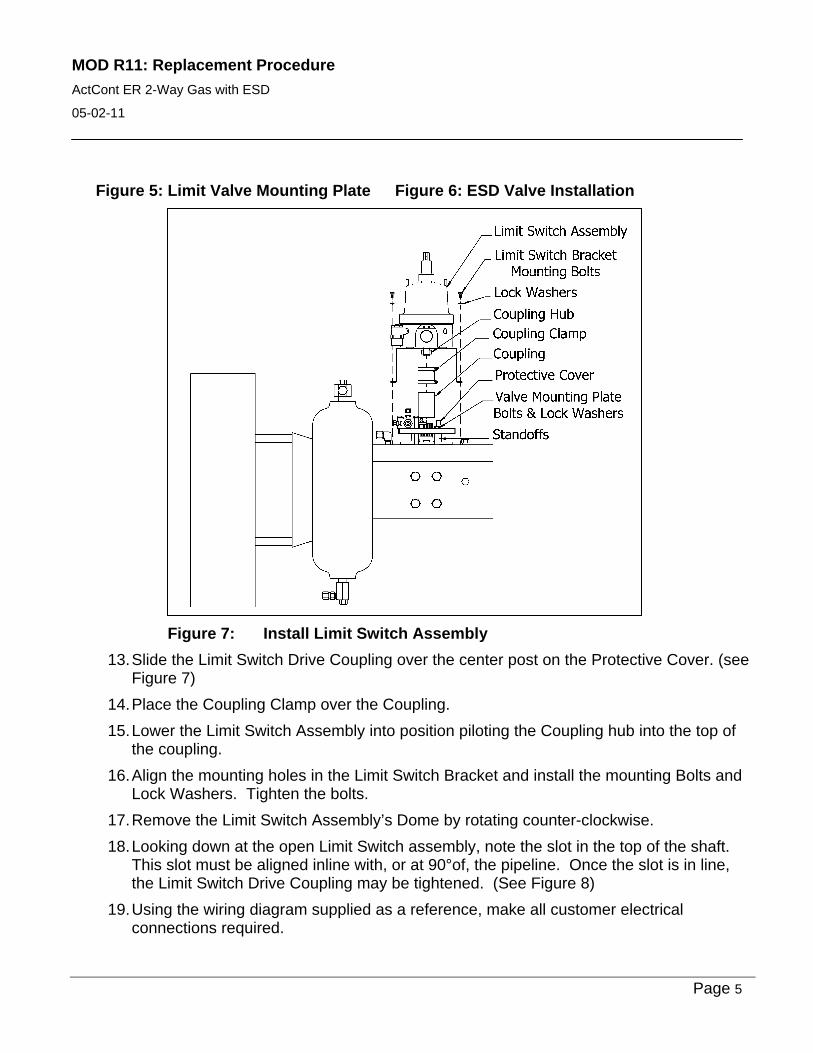
Figure 5: Limit Valve Mounting Plate Figure 6: ESD Valve Installation
Figure 7: Install Limit Switch Assembly
13. Slide the Limit Switch Drive Coupling over the center post on the Protective Cover. (see Figure 7)
14. Place the Coupling Clamp over the Coupling.
15. Lower the Limit Switch Assembly into position piloting the Coupling hub into the top of the coupling.
16. Align the mounting holes in the Limit Switch Bracket and install the mounting Bolts and Lock Washers. Tighten the bolts.
17. Remove the Limit Switch Assembly’s Dome by rotating counter-clockwise.
18. Looking down at the open Limit Switch assembly, note the slot in the top of the shaft. This slot must be aligned inline with, or at 90°of, the pipeline. Once the slot is in line, the Limit Switch Drive Coupling may be tightened. (See Figure 8)
19. Using the wiring diagram supplied as a reference, make all customer electrical connections required.
MOD R11: Replacement Procedure
ActCont ER 2-Way Gas with ESD
05-02-11
Page 6
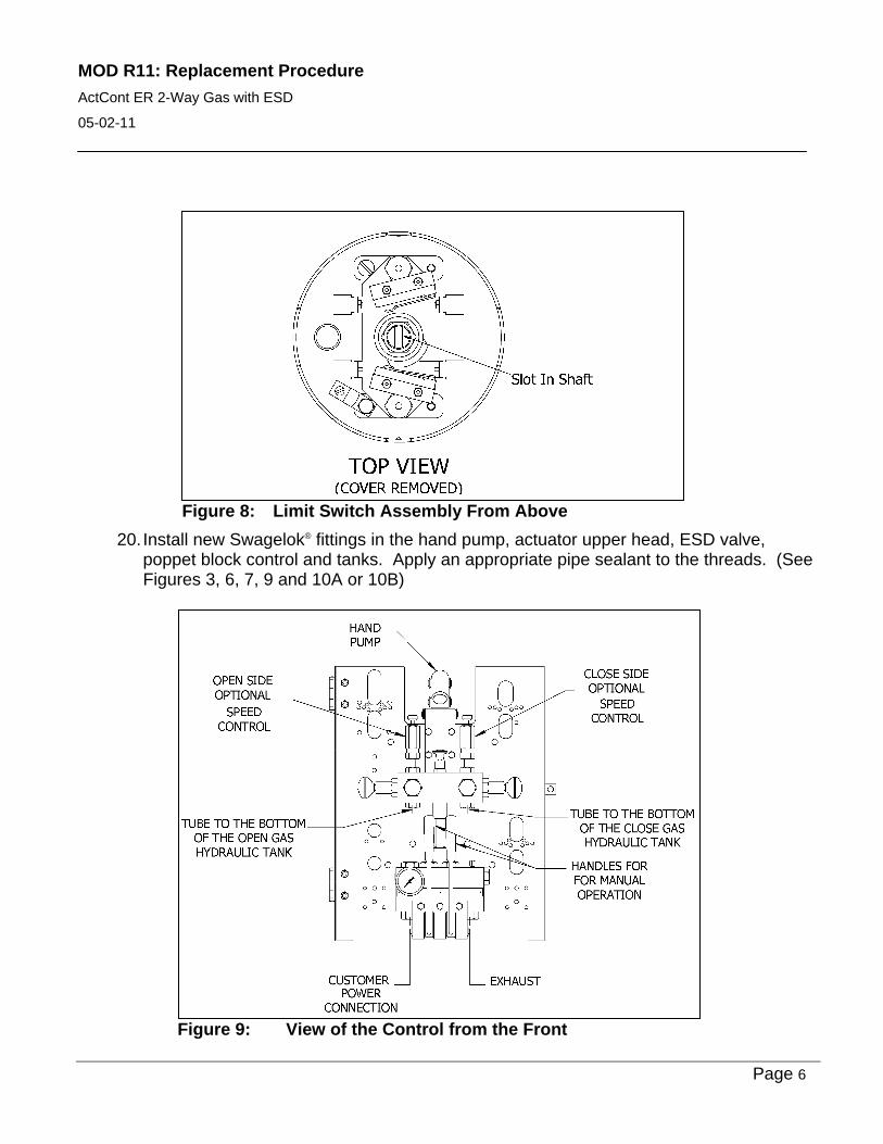
Figure 8: Limit Switch Assembly From Above
20. Install new Swagelok® fittings in the hand pump, actuator upper head, ESD valve, poppet block control and tanks. Apply an appropriate pipe sealant to the threads. (See Figures 3, 6, 7, 9 and 10A or 10B)
Figure 9: View of the Control from the Front

MOD R11: Replacement Procedure
ActCont ER 2-Way Gas with ESD
05-02-11
Page 7
21. Run tubing from the bottom of the gas hydraulic tanks to the suction ports located at the bottom of the hand pump valve body. Right tank (CLOSE) to the right suction port and the left tank (OPEN) to the left suction port, as you are facing the new hand pump (see Figure 3 and 9).
22. Run tubing from the discharge ports located on top of the hand pump valve body, or optional speed controls, if applicable. The right side of the pump runs to the port on the right in the upper head of the actuator (as you are facing the new hand pump). The left side of the pump runs to the port on the left in the upper head of the actuator. (Make sure you are using the ports in the upper head closest to control box, not the ones on the far side see Figure 3, 9 and 10A or 10B).
23. Run tubing from the CLOSE cylinder port of the poppet block control valve to the port in the diffuser assembly on top of the closing gas hydraulic tank (see Figure 3, 7 and 10A or 10B)
24. Run tubing from the OPEN cylinder port of the poppet block control valve to the port in the diffuser assembly on top of the opening gas hydraulic tank (see Figure 3, 7 and 10A or 10B).
NOTE: When facing the back of the control box the CLOSE cylinder port is on the left and the OPEN is on the right (see Figure 10A or 10B).
Figure 10A: View of the Control from the Back With ESD Fail Close (see Schematic 8357-S)

MOD R11: Replacement Procedure
ActCont ER 2-Way Gas with ESD
05-02-11
Page 8
Figure 10B: View of the Control from the Back with ESD Fail Open (re: Schematic 8863-S)
25. If an optional power storage tank is in use, find the optional connection for the power storage tank to the right of the OPEN cylinder port of the poppet block control valve, when facing the back of the control (see Figure 10A or 10B). Run tubing from this port to the top power storage as originally plumbed.
26A. Emergency Shutdown Fail Close Schematic 8357-S
The CLOSE pilot port of the Poppet Control Block will be connected to a Shuttle Valve, expanding it to two ports (see Figure 10A). a. Run tubing from one of the Shuttle Valve “In” ports to the cylinder port of the ESD
valve at the actuator. b. Run the rubbing from the second Shuttle Valve “In” port to the cylinder port of the
Close Solenoid Valve.
26B. Emergency Shutdown Fail Open Schematic 8863-S
The OPEN pilot port of the Poppet Control Block will be connected to a Shuttle Valve, expanding it to two ports (see Figure 10B). a. Run tubing from one of the Shuttle Valve “In” ports to the cylinder port of the ESD
valve at the actuator. b. Run the tubing from the second Shuttle Valve “In” port to the cylinder port of the
Open Solenoid Valve.

MOD R11: Replacement Procedure
ActCont ER 2-Way Gas with ESD
05-02-11
Page 9
27. Run tubing from the pilot pressure port of the Poppet Control Block to the power port of the ESD valve at the actuator and the pressure port of both the Open and the Close Solenoid Valves.
28. Run tubing from the cylinder port of the Open Solenoid Valve to the Open pilot port of the Poppet Control Block.
29. Connect the pilot port of the ESD Valve to the customer supplied pilot source.
30. Re-plumb the customer power connection and re-plumb the exhaust, or install muffler, on the poppet block control valve.
Replacing the Hydraulic Fluid and Purging the System 1. Fill both of the gas hydraulic tanks to required operating level.
2. Use the hand pump to close or open the actuator to purge the actuator and hydraulic lines. To stroke the actuator manually, either open or closed, select the appropriate knob on the selector valve located on the hand pump. This knob is selected by pressing inward toward the pump center.
Note: The pump has a label designating which knob is open and close.
3. Using the supplied pump handle, raise the hand pump clevis, which will draw hydraulic fluid into the pump. Pull the handle downward to discharge hydraulic fluid into the actuator. Repeat this process until the actuator reaches its end of stroke.
4. When the pumping cycle is completed, depress the manual relief valve located top center of the selector valve on the pump and pull the pump ram back into the pump body.
MOD R11: Replacement Procedure
ActCont ER 2-Way Gas with ESD
05-02-11
Page 10
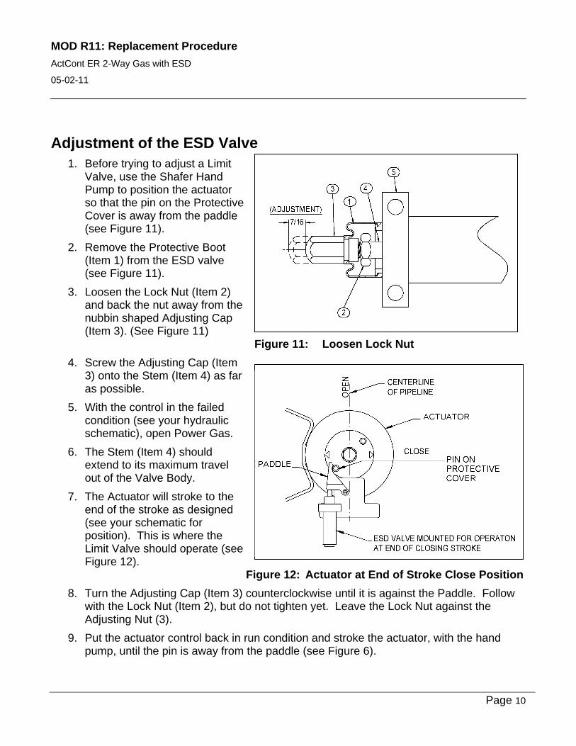
Adjustment of the ESD Valve 1. Before trying to adjust a Limit
Valve, use the Shafer Hand Pump to position the actuator so that the pin on the Protective Cover is away from the paddle (see Figure 11).
2. Remove the Protective Boot (Item 1) from the ESD valve (see Figure 11).
3. Loosen the Lock Nut (Item 2) and back the nut away from the nubbin shaped Adjusting Cap (Item 3). (See Figure 11)
Figure 11: Loosen Lock Nut
4. Screw the Adjusting Cap (Item 3) onto the Stem (Item 4) as far as possible.
5. With the control in the failed condition (see your hydraulic schematic), open Power Gas.
6. The Stem (Item 4) should extend to its maximum travel out of the Valve Body.
7. The Actuator will stroke to the end of the stroke as designed (see your schematic for position). This is where the Limit Valve should operate (see Figure 12).
Figure 12: Actuator at End of Stroke Close Position
8. Turn the Adjusting Cap (Item 3) counterclockwise until it is against the Paddle. Follow with the Lock Nut (Item 2), but do not tighten yet. Leave the Lock Nut against the Adjusting Nut (3).
9. Put the actuator control back in run condition and stroke the actuator, with the hand pump, until the pin is away from the paddle (see Figure 6).

MOD R11: Replacement Procedure
ActCont ER 2-Way Gas with ESD
05-02-11
Page 11
10. Turn the Adjusting Nut counterclockwise until the distance between the Adjusting Nut and the Lock Nut is close to 3/8" (see Figure 13).
Figure 13: Set Acorn Adjusting Cap
Caution: Use caution not to over stroke the Limit Valve. If the adjusting cap is adjusted away from the valve too far, resulting in the paddle trying to stroke the valve past its limits, the poppet will be destroyed in the valve (see Figure 14).
Figure 12: Maximum Adjustment 7/16"
11. Lock the Adjusting Cap in place by tightening the Lock Nut against it. Do not move the Adjusting Cap while locking.
12. Stroke the actuator in both directions using power gas pressure and operating the manual handles on the poppet block control valve.
MOD R11: Replacement Procedure
ActCont ER 2-Way Gas with ESD
05-02-11
Page 12
13. Test the ESD valve to determine if it is activates at the end of stroke and the control is neutralized. If so, adjustment is complete and the Protective Boot can be reinstalled, after packing stem area with light grease.
14. If the valve does not work correctly (there is an audible sign that power gas is leaking out of the exhaust of the poppet block) or there has been adjustment made to the actuator stops. Adjust the valve in small increments until the control is neutralized at the end of the stroke. The stroke of the valve must not exceed 7/16"; see Caution above and Figure 7.
15. The automatic features of the control circuit can now be used.
16. The hand pump will automatically shift to neutral when either the OPEN tank or the CLOSE tank is pressurized during an automatic cycle of the control circuit.
Limit Switch Adjustment Procedure
SERVICE Shafer rotary position indicating switches, Switchpak Models SW4, are supplied with a maximum of 8 switches, adjustable through 360 angular degrees of shaft rotation. The enclosure is suitable for installation in Class I, Div. 1 Group C and D Hazardous Locations.
SETPOINT ADJUSTMENT
CAUTION: Disconnect Electrical Power Supply Before Beginning Procedure
1. Determine valve operator position, open or closed, by comparing arrows on the Switch Position Indicator to name tags on operator.
2. Once position is determined, remove the limit switch assembly’s Dome Cover by rotating counter clockwise from base.
3. Located on the actuator shaft are both Actuator Cams and Spacer Rings. The Spacer Rings have a smooth finish on the outer edge while the Actuator Cams have teeth around the edge and an extended lobe on a portion of the edge to cam actuate the switch (see illustrations on sheet 15 and 16).
MOD R11: Replacement Procedure
ActCont ER 2-Way Gas with ESD
05-02-11
Page 13
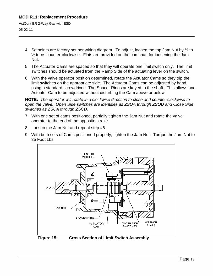
4. Setpoints are factory set per wiring diagram. To adjust, loosen the top Jam Nut by ¼ to ½ turns counter-clockwise. Flats are provided on the camshaft for loosening the Jam Nut.
5. The Actuator Cams are spaced so that they will operate one limit switch only. The limit switches should be actuated from the Ramp Side of the actuating lever on the switch.
6. With the valve operator position determined, rotate the Actuator Cams so they trip the limit switches on the appropriate side. The Actuator Cams can be adjusted by hand, using a standard screwdriver. The Spacer Rings are keyed to the shaft. This allows one Actuator Cam to be adjusted without disturbing the Cam above or below.
NOTE: The operator will rotate in a clockwise direction to close and counter-clockwise to open the valve. Open Side switches are identifies as ZSOA through ZSOD and Close Side switches as ZSCA through ZSCD.
7. With one set of cams positioned, partially tighten the Jam Nut and rotate the valve operator to the end of the opposite stroke.
8. Loosen the Jam Nut and repeat step #6.
9. With both sets of Cams positioned properly, tighten the Jam Nut. Torque the Jam Nut to 35 Foot Lbs.
Figure 15: Cross Section of Limit Switch Assembly
MOD R11: Replacement Procedure
ActCont ER 2-Way Gas with ESD
05-02-11
Page 14
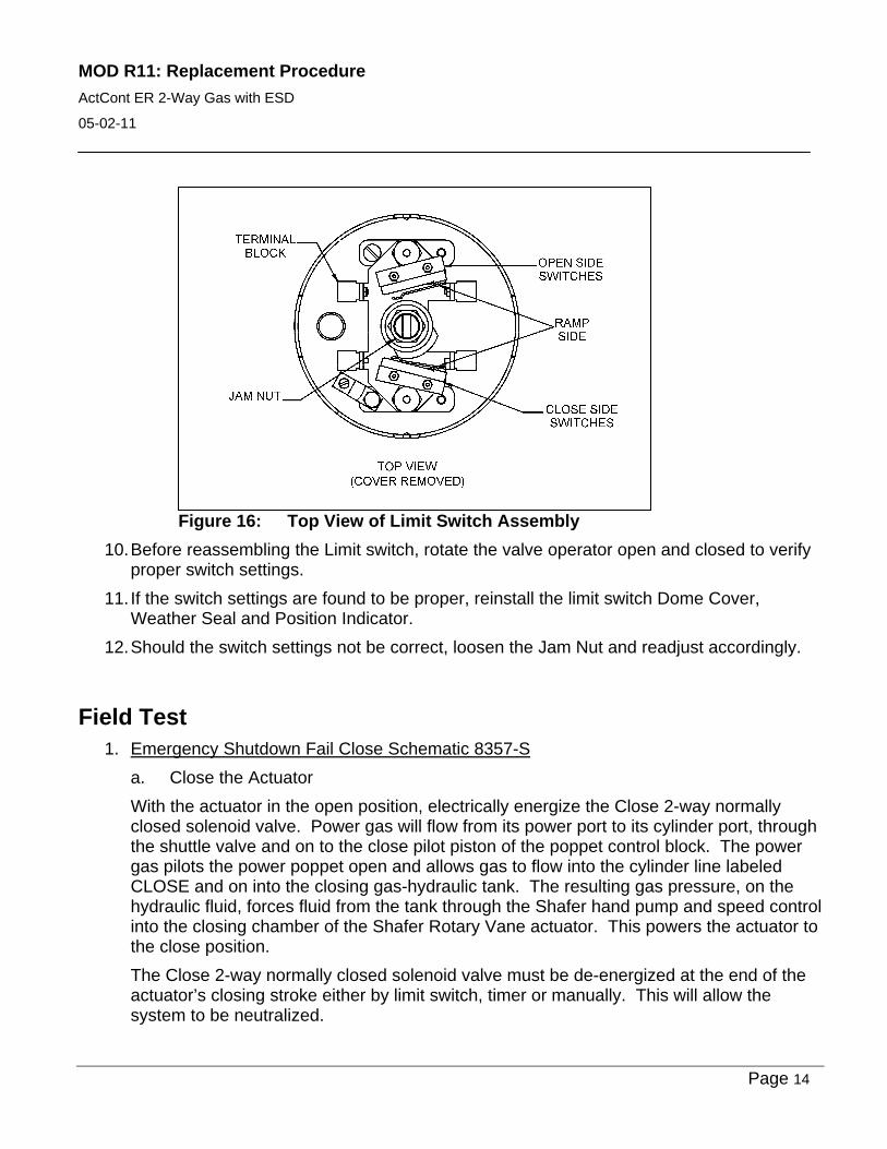
Figure 16: Top View of Limit Switch Assembly
10. Before reassembling the Limit switch, rotate the valve operator open and closed to verify proper switch settings.
11. If the switch settings are found to be proper, reinstall the limit switch Dome Cover, Weather Seal and Position Indicator.
12. Should the switch settings not be correct, loosen the Jam Nut and readjust accordingly.
Field Test 1. Emergency Shutdown Fail Close Schematic 8357-S
a. Close the Actuator
With the actuator in the open position, electrically energize the Close 2-way normally closed solenoid valve. Power gas will flow from its power port to its cylinder port, through the shuttle valve and on to the close pilot piston of the poppet control block. The power gas pilots the power poppet open and allows gas to flow into the cylinder line labeled CLOSE and on into the closing gas-hydraulic tank. The resulting gas pressure, on the hydraulic fluid, forces fluid from the tank through the Shafer hand pump and speed control into the closing chamber of the Shafer Rotary Vane actuator. This powers the actuator to the close position.
The Close 2-way normally closed solenoid valve must be de-energized at the end of the actuator’s closing stroke either by limit switch, timer or manually. This will allow the system to be neutralized.
MOD R11: Replacement Procedure
ActCont ER 2-Way Gas with ESD
05-02-11
Page 15
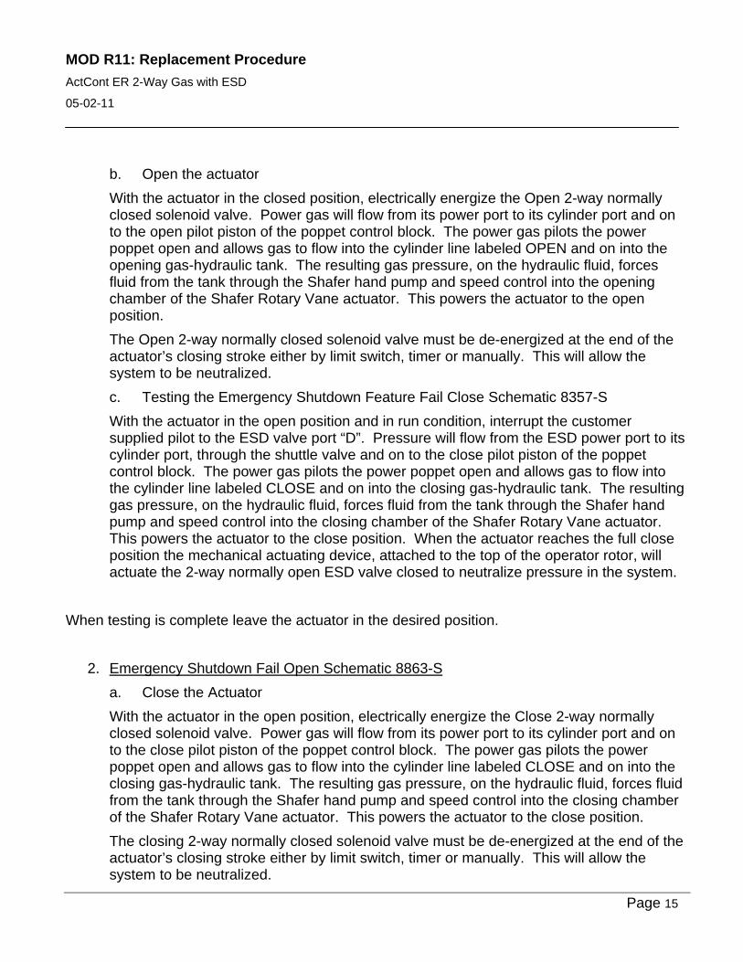
b. Open the actuator
With the actuator in the closed position, electrically energize the Open 2-way normally closed solenoid valve. Power gas will flow from its power port to its cylinder port and on to the open pilot piston of the poppet control block. The power gas pilots the power poppet open and allows gas to flow into the cylinder line labeled OPEN and on into the opening gas-hydraulic tank. The resulting gas pressure, on the hydraulic fluid, forces fluid from the tank through the Shafer hand pump and speed control into the opening chamber of the Shafer Rotary Vane actuator. This powers the actuator to the open position.
The Open 2-way normally closed solenoid valve must be de-energized at the end of the actuator’s closing stroke either by limit switch, timer or manually. This will allow the system to be neutralized.
c. Testing the Emergency Shutdown Feature Fail Close Schematic 8357-S
With the actuator in the open position and in run condition, interrupt the customer supplied pilot to the ESD valve port “D”. Pressure will flow from the ESD power port to its cylinder port, through the shuttle valve and on to the close pilot piston of the poppet control block. The power gas pilots the power poppet open and allows gas to flow into the cylinder line labeled CLOSE and on into the closing gas-hydraulic tank. The resulting gas pressure, on the hydraulic fluid, forces fluid from the tank through the Shafer hand pump and speed control into the closing chamber of the Shafer Rotary Vane actuator. This powers the actuator to the close position. When the actuator reaches the full close position the mechanical actuating device, attached to the top of the operator rotor, will actuate the 2-way normally open ESD valve closed to neutralize pressure in the system.
When testing is complete leave the actuator in the desired position.
2. Emergency Shutdown Fail Open Schematic 8863-S
a. Close the Actuator
With the actuator in the open position, electrically energize the Close 2-way normally closed solenoid valve. Power gas will flow from its power port to its cylinder port and on to the close pilot piston of the poppet control block. The power gas pilots the power poppet open and allows gas to flow into the cylinder line labeled CLOSE and on into the closing gas-hydraulic tank. The resulting gas pressure, on the hydraulic fluid, forces fluid from the tank through the Shafer hand pump and speed control into the closing chamber of the Shafer Rotary Vane actuator. This powers the actuator to the close position.
The closing 2-way normally closed solenoid valve must be de-energized at the end of the actuator’s closing stroke either by limit switch, timer or manually. This will allow the system to be neutralized.
MOD R11: Replacement Procedure
ActCont ER 2-Way Gas with ESD
05-02-11
Page 16
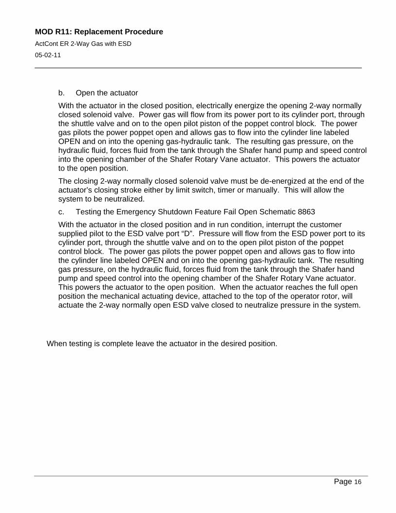
b. Open the actuator
With the actuator in the closed position, electrically energize the opening 2-way normally closed solenoid valve. Power gas will flow from its power port to its cylinder port, through the shuttle valve and on to the open pilot piston of the poppet control block. The power gas pilots the power poppet open and allows gas to flow into the cylinder line labeled OPEN and on into the opening gas-hydraulic tank. The resulting gas pressure, on the hydraulic fluid, forces fluid from the tank through the Shafer hand pump and speed control into the opening chamber of the Shafer Rotary Vane actuator. This powers the actuator to the open position.
The closing 2-way normally closed solenoid valve must be de-energized at the end of the actuator’s closing stroke either by limit switch, timer or manually. This will allow the system to be neutralized.
c. Testing the Emergency Shutdown Feature Fail Open Schematic 8863
With the actuator in the closed position and in run condition, interrupt the customer supplied pilot to the ESD valve port “D”. Pressure will flow from the ESD power port to its cylinder port, through the shuttle valve and on to the open pilot piston of the poppet control block. The power gas pilots the power poppet open and allows gas to flow into the cylinder line labeled OPEN and on into the opening gas-hydraulic tank. The resulting gas pressure, on the hydraulic fluid, forces fluid from the tank through the Shafer hand pump and speed control into the opening chamber of the Shafer Rotary Vane actuator. This powers the actuator to the open position. When the actuator reaches the full open position the mechanical actuating device, attached to the top of the operator rotor, will actuate the 2-way normally open ESD valve closed to neutralize pressure in the system.
When testing is complete leave the actuator in the desired position.
MOD R11: Replacement Procedure
ActCont ER 2-Way Gas with ESD
05-02-11
Page 17
MOD R11: Replacement Procedure
ActCont ER 2-Way Gas with ESD
05-02-11
Page 18
MOD R11: Replacement Procedure
ActCont ER 2-Way Gas with ESD
05-02-11
If any further information is required, please feel free to contact:
Emerson Process Management
Valve Automation Inc.
2500 Park Avenue West
Mansfield, Ohio 44906
Phone: (419) 529-4311
Fax (419) 529-3688
Please visit our website for up to date product data. www.shafervalve.com
All Rights Reserved
The contents of this publication are presented for informational purpose only, and while every effort has been made to ensure their accuracy, they are not to be construed as warranties or guarantees, express or implied, regarding the products or services described herein or their use or applicability. We reserve the right to modify or improve the designs or specifications of such products at any time with out notice.
Trademarks owned by other companies that are referred to in our product literature include: Swagelok®
Related Documents