Farwick 1 ActivSense Sidestick A Force Sensing and Force Feedback Joystick by Kobbe Farwick Advisor: Dr. Bridget Benson Electrical Engineering Department California Polytechnic State University San Luis Obispo June 2017

Welcome message from author
This document is posted to help you gain knowledge. Please leave a comment to let me know what you think about it! Share it to your friends and learn new things together.
Transcript

Farwick 1
ActivSense Sidestick
A Force Sensing and Force Feedback Joystick
by
Kobbe Farwick
Advisor: Dr. Bridget Benson
Electrical Engineering Department
California Polytechnic State University
San Luis Obispo
June 2017

Farwick 2
Table of Contents
ABSTRACT ....................................................................................................................................... 9
ACKNOWLEDGEMENTS ................................................................................................................... 10
BACKGROUND ................................................................................................................................ 11
ADVANCEMENT IN AIRCRAFT FLIGHT CONTROLS ...................................................................... 11
PRODUCT DESCRIPTION ................................................................................................................. 13
MARKET RESEARCH....................................................................................................................... 14
CURRENT SOLUTIONS ................................................................................................................ 14
CUSTOMER ARCHETYPE ................................................................................................................. 16
COMMERCIAL AIRLINES ............................................................................................................. 16
DEFENSE INDUSTRY ................................................................................................................... 16
GENERAL AVIATION .................................................................................................................. 16
MARKET SHARE ......................................................................................................................... 17
BUSINESS MODEL CANVAS ............................................................................................................ 18
MARKETING REQUIREMENTS ......................................................................................................... 19
PROGRAMMABLE FORCE GRADIENTS ........................................................................................ 20
REDUNDANCY ............................................................................................................................ 20
SMALL FORM FACTOR ............................................................................................................... 20
AVIONICS BACKWARD COMPATIBILITY ..................................................................................... 21
SYSTEM DIAGRAMS ....................................................................................................................... 23
LEVEL 0 DIAGRAM ..................................................................................................................... 23
LEVEL 1 DIAGRAM ..................................................................................................................... 23
USER INPUT ........................................................................................................................... 24
JOYSTICK CONTROL ............................................................................................................... 24
SIMULATOR DATA ................................................................................................................. 24
USB TO PC ............................................................................................................................ 24
SOFTWARE FUNCTIONAL DIAGRAM ........................................................................................... 25
SYSTEM REQUIREMENTS ................................................................................................................ 26
SYSTEM DESIGN ............................................................................................................................. 27
HARDWARE DESIGN ................................................................................................................... 27
LOAD CELL ............................................................................................................................ 27
STRAIN GAUGE MEASUREMENT ............................................................................................ 27

Farwick 3
GIMBAL MECHANISM............................................................................................................. 28
SIDESTICK GRIP ..................................................................................................................... 29
SERVOS .................................................................................................................................. 30
USB HUMAN INTERFACE DEVICE (HID) ............................................................................... 31
MICROCONTROLLER .............................................................................................................. 31
PROTOTYPE BOARD ............................................................................................................... 32
WINDOWS USER GUI ............................................................................................................. 32
FORCE FEEDBACK CONCEPT .................................................................................................. 34
CONTROL SYSTEM DESIGN .................................................................................................... 36
SYSTEM COMPONENT CHARACTERIZATION ................................................................................... 39
LOAD CELL CHARACTERIZATION ............................................................................................... 39
POTENTIOMETER RANGE SCALING ............................................................................................. 41
SERVO CHARACTERIZATION ...................................................................................................... 44
CONTROL SYSTEM TUNING AND SIMULATION ............................................................................... 45
ZIEGLER-NICHOLS TUNING METHOD ......................................................................................... 45
SIMULINK SYSTEM MODEL ........................................................................................................ 47
SYSTEM RESPONSE .................................................................................................................... 51
SYSTEM TESTING ........................................................................................................................... 54
FORCE FEEDBACK TESTING ....................................................................................................... 54
OVERALL SYSTEM TEST AND RESULTS ...................................................................................... 56
PROJECT SCHEDULE ....................................................................................................................... 57
TIMELINE AND MAJOR MILESTONES .......................................................................................... 57
TASK BREAKDOWN .................................................................................................................... 59
COSTS AND RESOURCES ............................................................................................................. 61
REQUIRED SKILLS ...................................................................................................................... 62
CONCLUSION AND FUTURE IMPROVEMENTS .................................................................................. 63
MECHANICAL ASSEMBLIES ........................................................................................................ 63
SERVO ........................................................................................................................................ 63
LOAD CELL ................................................................................................................................ 63
MICROCONTROLLER .................................................................................................................. 64
ADDITIONAL SOFTWARE ............................................................................................................ 64
ANALYSIS OF SENIOR PROJECT ...................................................................................................... 65
Farwick 4
SUMMARY OF FUNCTIONAL REQUIREMENTS .............................................................................. 65
PRIMARY CONSTRAINTS ............................................................................................................ 65
ECONOMIC IMPACT .................................................................................................................... 65
HUMAN CAPITAL ................................................................................................................... 65
FINANCIAL CAPITAL .............................................................................................................. 65
NATURAL CAPITAL ................................................................................................................ 66
COSTS AND TIMING ................................................................................................................ 66
MANUFACTURABILITY ............................................................................................................... 66
ENVIRONMENTAL IMPACT .......................................................................................................... 67
SUSTAINABILITY ........................................................................................................................ 68
ETHICAL IMPLICATIONS ............................................................................................................. 68
HEALTH AND SAFETY ................................................................................................................ 69
SOCIAL AND POLITICAL IMPLICATIONS ...................................................................................... 69
APPENDIX ...................................................................................................................................... 70
SCHEMATICS .............................................................................................................................. 70
CODE ......................................................................................................................................... 71
REFERENCES .................................................................................................................................. 77

Farwick 5
Figures
FIGURE 1- BAE SYSTEMS ACTIVE INCEPTOR DIAGRAM [4] ........................................................... 14
FIGURE 2- ACTIVE INCEPTOR ADVANTAGES [4] ............................................................................ 14
FIGURE 3- MARKET SHARE PIE CHART .......................................................................................... 17
FIGURE 4- BUSINESS MODEL CANVAS ........................................................................................... 18
FIGURE 5- ARINC 429 BUS TOPOLOGY ......................................................................................... 21
FIGURE 6- MARKETING DATA SHEET ............................................................................................. 22
FIGURE 7- LEVEL 0 BLACK BOX DIAGRAM .................................................................................... 23
FIGURE 8 – LEVEL 1 SYSTEM DIAGRAM ......................................................................................... 24
FIGURE 9 - SOFTWARE FLOW DIAGRAM ......................................................................................... 25
FIGURE 10 - SMD SENSORS M200 LOAD CELL [9] ........................................................................ 27
FIGURE 11- HX711 SCHEMATIC [10] ............................................................................................. 28
FIGURE 12 – GIMBAL 3D MODEL ................................................................................................... 28
FIGURE 13 - 3D PRINTED GIMBAL ASSEMBLY ............................................................................... 29
FIGURE 14 - MOUNTED GIMBAL .................................................................................................... 29
FIGURE 15 - GRIP 3D MODEL ......................................................................................................... 30
FIGURE 16 - 3D PRINTED GRIP WITH LOAD CELL ATTACHED ........................................................ 30
FIGURE 17 - SAVOX SA-1283SG SERVO [11] ................................................................................ 30
FIGURE 18 - TEENSYDUINO 3.2 [12] .............................................................................................. 31
FIGURE 19 - PROTOTYPE BOARD (TOP) .......................................................................................... 32
FIGURE 20 - PROTOTYPE BOARD (BOTTOM) .................................................................................. 32
FIGURE 21 - WINDOWS USER GUI ................................................................................................. 34
FIGURE 22 - SERVO POSITION VS FORCE GRAPH ............................................................................ 35
FIGURE 23 - IN-FLIGHT FORCE FEEDBACK VISUALIZATION ........................................................... 36
FIGURE 24 - PID SOFTWARE FLOW DIAGRAM ............................................................................... 37
FIGURE 25 - CONTROL SYSTEM DIAGRAM ..................................................................................... 38
FIGURE 26 - TEST SETUP FOR LOAD CELL ...................................................................................... 39
FIGURE 27 - ADC OUTPUT (X AXIS) ............................................................................................. 40
FIGURE 28- ADC OUTPUT (Y AXIS) .............................................................................................. 40

Farwick 6
FIGURE 29 - DIFFERENTIAL VOLTAGE VS FORCE (Y AXIS) ............................................................ 41
FIGURE 30 - DIFFERENTIAL VOLTAGE VS FORCE (X AXIS) ............................................................ 41
FIGURE 31 - POTENTIOMETER ADC OUTPUT (X AXIS) .................................................................. 43
FIGURE 32 - POTENTIOMETER ADC OUTPUT (Y AXIS) .................................................................. 43
FIGURE 33 - SERVO TIME DOMAIN STEP RESPONSE ....................................................................... 44
FIGURE 34 - EXPERIMENTAL OSCILLATORY RESPONSE .................................................................. 46
FIGURE 35 - EXPERIMENTALLY TUNED PI STEP RESPONSE ............................................................ 47
FIGURE 36 - SIMULINK CONTROL SYSTEM MODEL ........................................................................ 47
FIGURE 37 - SIMULINK MODEL (PART 1) ....................................................................................... 48
FIGURE 38 - SIMULINK MODEL (PART 2) ....................................................................................... 48
FIGURE 39 - EXPERIMENTALLY TUNED PD SIMULATION ............................................................... 49
FIGURE 40 - SIMULINK TUNED PD CONTROL SIMULATION ............................................................ 50
FIGURE 41 - SIMULATION OF VARYING FORCE GRADIENT ............................................................. 51
FIGURE 42 - SYSTEM RESPONSE TO SINUSOIDAL INPUT (ZIEGLER-NICHOLS) ................................ 52
FIGURE 43 - SYSTEM RESPONSE TO SINUSOIDAL INPUT (ADJUSTED Z-N) ...................................... 52
FIGURE 44 - SYSTEM RESPONSE TO SINUSOIDAL INPUT (OSCILLATORY) ....................................... 53
FIGURE 45 - EXPERIMENTAL AND THEORETICAL FORCE AND POSITION RELATION ....................... 54
FIGURE 46 - POSITION VS FORCE WITH VARYING KG ..................................................................... 55
FIGURE 47 - WINTER 2017 SCHEDULE ........................................................................................... 58
FIGURE 48 - SPRING 2017 SCHEDULE ............................................................................................. 58
FIGURE 49 - MAIN SCHEMATIC ...................................................................................................... 71

Farwick 7
Tables
TABLE 1- CUSTOMER NEEDS TABLE .............................................................................................. 19
TABLE 2 - ENGINEERING REQUIREMENTS ...................................................................................... 26
TABLE 3 - GUI INTERFACE DESCRIPTION....................................................................................... 33
TABLE 4- POTENTIOMETER CALIBRATION DATA ........................................................................... 42
TABLE 5 - ZIEGLER-NICHOLS VALUES [13] ................................................................................... 45
TABLE 6 – EXPERIMENTALLY TUNED PID CONSTANTS ................................................................. 46
TABLE 7 - PID PARAMETERS FROM SIMULINK ............................................................................... 49
TABLE 8 - SYSTEM TEST RESULTS ................................................................................................. 56
TABLE 9- MAJOR MILESTONES ...................................................................................................... 57
TABLE 10 - BILL OF MATERIALS .................................................................................................... 61

Farwick 8
Equations
EQUATION 1 - FORCE AND POSITION RELATION ............................................................................. 34
EQUATION 2 - APPROXIMATE DERIVATIVE EQUATION ................................................................... 37
EQUATION 3 - APPROXIMATE INTEGRAL EQUATION ...................................................................... 37
EQUATION 4 - POTENTIOMETER TRANSLATION EQUATIONS .......................................................... 43
EQUATION 5 - SERVO TIME DOMAIN UNIT STEP RESPONSE ........................................................... 44
EQUATION 6 - SERVO TRANSFER FUNCTION .................................................................................. 44
EQUATION 7 - DISCRETE PID TRANSFER FUNCTION [13] ............................................................... 45
EQUATION 8 - KI AND KD EQUATIONS [13] ..................................................................................... 45

Farwick 9
Abstract
As aircraft systems continue to become more integrated and fully electronic, hence fly-by-wire,
the pilot is slowly losing the physical cues that were once relied upon for the safe operation of
the aircraft. Many commercial airliners, such as Airbus, use passive sidesticks that integrate with
the electronic flight controls system. These sidesticks move much like a gaming joystick which
results in the pilot not having any “feel” for the aerodynamic forces present on the control
surfaces. Without the force feedback of a mechanically linked control system the pilot could
inadvertently stall the aircraft or place it into an unstable flight condition. To combat this, the
active sidestick will include a servo mechanism to provide force feedback and use strain gauges
to determine the force applied to the sidestick by the pilot. Multiple sources of data, such as the
aircraft configuration and critical speeds can be used to produce a force gradient which resist a
pilot’s inputs if they are exceeding the aircraft capabilities.
The active sidestick will interface with PC based flight simulation to control an aircraft and
receive flight characteristic data to properly adjust the forces present on the sidestick. Being
solely based on force input for aircraft control, if there were to be an in-flight failure of the
servos the pilot would still be able to control the aircraft by force alone. Such a sidestick could
be used in any number of aviation applications; it would improve the safety of unmanned aircraft
operations in which the pilot/operator receives no tactile feedback at the controls. It could also
become physically small enough and cost effective to be outfitted in modern general aviation
aircraft to prevent the all-too-common loss of control scenario upon landing or takeoff.

Farwick 10
Acknowledgements
My senior design project would not have been possible without the support of Cal Poly’s
Autonomous Flight Lab (AFL). Dr. Aaron Drake of the aerospace department directed AFL
funding towards this project which allowed for the purchase of necessary parts and materials.
Aerospace engineering graduate student and AFL member Shaun Wixted provided the 3D
printing capability. This project culminates a seven-year journey towards a degree in electrical
engineering so it is fitting that I also recognize those who provided encouragement and support
along the way. Thank you to my parents for doing what they could to make sure that I could
focus my attention on my studies. I cannot begin to name all of the friends and family who were
present in the pursuit of my degree, but to all of you –
Thank You

Farwick 11
Background
Advancement in Aircraft Flight Controls
In traditional, fully analog aircraft the pilots were required to process over a dozen instrument
readings and understand the relationship between pitch, power, bank angle and many other vital
flight characteristics [1]. This requires a complex scan of multiple instruments to determine the
correct control inputs; in some cases, misinterpretation of instrument or physical cues could
result in loss of control. Fly-by-wire systems have come into existence not only because of
advanced aircraft electronics (avionics) but to assist pilots in control of the aircraft. Fly-by-wire
systems implement highly sensitive inertial sensors and computers to command the flight control
surfaces to stay on a chosen trajectory and airspeed target [1].
Unfortunately, fly-by-wire systems are not fool-proof and have inherent disadvantages in their
current state. In 1988 a French Airbus A320, a popular commercial airliner, crashed at an
airshow which was determined to be a result of the innovative fly-by-wire system [2]. The A320
implemented a fly-by-wire system that relied primarily on electrical signals from a sidestick
controller; known as a sidestick due to being mounted to the outside edge of the cockpit to avoid
interfering with pilot movement [2]. The sidestick sends electrical signals to a computer which
translates them into commands for the aircraft control surfaces. In the case of the 1988 accident
it was determined that the fly-by-wire system had not failed but rather was caused by loss of
control by the pilot. The pilot likely sent the aircraft into a stall without having the physical
feedback cues that a mechanically-linked flight control system would provide.
This is where active sidestick, sometimes referred to as active inceptors, come into play. Active
sidesticks employ tactile and visual feedback to the pilots. These essential situational awareness
cues are missing from many fly-by-wire aircraft such as the aforementioned Airbus A320,
Airbus A400M, Dassault Rafale and Embraer Legacy 500 [3]. Active sidesticks allow flight
control computers to move both the pilot and copilot sidesticks together as well as when the
autopilot makes inputs to the flight control system [3]. Being fully electronic, the sidesticks can
be modified in software to provide force feedback that varies the control input effort required at
different phases of flight [3].Thus active sidesticks are crucial for filling the gap between
traditional, mechanically linked systems to fully fly-by-wire control systems.

Farwick 12
Furthermore, as unmanned aircraft technology advances and continues to become popularized,
the need for active sidestick systems will continue to increase. Naturally, a person piloting a
remotely-piloted aircraft (RPA) is completely removed from the physical feedback loop and has
an absolute minimum of situational awareness. In this environment, an active sidestick becomes
incredibly important for safety of flight.

Farwick 13
Product Description
ActivSense is the next step in responsive, precise control for aerospace and medical applications.
The ActivSense control stick is a common solution to these problems experienced across
multiple industries. ActivSense continuously monitors the operator’s force input in high fidelity
and translates the data into servo driven motion of the control stick as well as drive signals for
the end system. ActivSense will also receive data from the end system to properly adjust the
force required by the user to move the control stick. With no moving parts required to sense
control input there is high repeatability and close to zero hardware failure. In comparison,
potentiometer, Hall effect, and inductive sensing technology all have moving parts with very low
sensing resolution and are prone to mechanical failure.
The ActivSense sidestick will be differentiated from current solutions by form factor,
input/output and multiple marketable applicability. Traditionally an active sidestick might only
be found in large aircraft but ActivSense will be designed with unmanned aircraft, medical and
general aviation industries in mind. The end user will have greater freedom of tuning the force
feedback gradients and can source independent flight data through a standard interface.

Farwick 14
Market Research
Current Solutions
A leader in the industry, BAE Systems is providing a commercial active sidestick product to
aircraft manufacturers who are willing to take the next step in technology. BAE describes active
inceptor systems as providing tactile cueing to pilots by feeding information from the aircraft fly-
by-wire system back to the sidestick [4]. BAE Systems created the simplified system diagram of
an active inceptor as shown in figure 1 below.
Figure 1- BAE Systems Active Inceptor Diagram [4]
The many benefits of using an active inceptor over a passive electronic sidestick or mechanical
controls are clearly defined in the table seen in figure 2 below.
Figure 2- Active Inceptor Advantages [4]

Farwick 15
BAE’s system is designed with commercial airliner aircraft in mind. The active inceptor relies on
existing fly-by-wire architecture and is physically large. Thus, it is better suited for larger
aircraft. What makes BAE’s solution unique is the ability to allow commercial aircraft
manufacturers to make use of a technology once reserved for military and space aircraft. For
example, business jet manufacturer Gulfstream is implementing BAE’s active inceptors which
will mark a first for the entire business jet industry.

Farwick 16
Customer Archetype
Commercial Airlines
Commercial airliner manufacturers continue to maintain and deliver aircraft. Airbus has a total of
16,731 deliveries planned for 2016 [5]. With the large number of aircraft being produced there is
a large market for installation of active sidesticks before reaching the final customer. Boeing,
another prominent aircraft manufacturer, estimates there are over 10,000 Boeing aircraft in
service not including recent deliveries [6]. Just considering these two primary aircraft
manufacturers it is evident there is a possibility for a significant market share in manufacturing
and retrofit businesses. These prospective customers would benefit from the additional safety
made possible by active sidesticks. Public exposure to these technologies may also result in
greater peace of mind in airline passengers.
Defense Industry
There are a few avenues into the defense industry to be considered. While the active sidestick
technology is not a new concept in military aircraft most airframes employed by the armed
forces do not take advantage of this technology. Unmanned aircraft would see a decrease in
mishaps if active sidesticks were implemented in the ground control stations. General Atomics,
the dominant unmanned aircraft manufacturer, supports 678 drones currently in use by the
military [7]. With unmanned aircraft technology still reaching maturity it is the optimal time to
introduce the active sidestick technology. Remotely piloted aircraft (RPA) operators would
benefit from the tactile feedback; in addition to a remote visual feed, the pilot would receive
force feedback to confirm the movement they perceive visually. With millions being spent on the
maintenance and new acquisitions of RPAs there is an obvious benefit to the U.S. Department of
Defense to invest in active sidestick technology; mishaps and expensive accidents would be
reduced.
General Aviation
While it is the smallest market there is still a great benefit to be had by general aviation if active
sidesticks are adopted. It would be difficult to integrate the technology into traditionally analog
aircraft such as early model Cessna aircraft, but much easier for late model aircraft. As an
example, Cirrus Aircraft builds a production line aircraft that incorporates a sidestick and glass
cockpit displays. Cirrus models such as the SR-22 famously incorporate a parachute into the

Farwick 17
airframe; the next step in safety would be implementing the active sidestick. Cirrus aircraft are
uniquely situated to make this possible as they already have digital autopilot and instrument
systems. Outside of certified production aircraft, it would be easier to incorporate active
sidesticks into experimental aircraft. With fewer Federal Aviation Administration (FAA)
regulations it would be the ideal starting point for introducing these sidesticks into the general
aviation market.
Market Share
While there is a large a number of commercial aircraft currently in service, this segment is not
expected to make up the largest market share. Retrofit and stringent certification requirements by
the FAA will severely limit the ability of airlines to implement the technology in airliners
currently being operated. Military aircraft are less hindered by such restrictions; thus, the defense
industry is expected to have the most significant market share. Given the number of aircraft in
operation for each industry, the following market share diagram was developed.
Currently BAE Systems is the market leader in foreign defense and commercial aircraft
manufacturers. Lockheed Martin, a defense contractor, manufactures the F-35 fighter jet which
incorporates an active sidestick.
Figure 3- Market Share Pie Chart
25%
55%
5%
15%
Market Share
Commerical Aircraft Manufacturers Defense Industry
Medical Industry General Aviation

Farwick 18
Business Model Canvas
Figure 4- Business Model Canvas
Farwick 19
Marketing Requirements
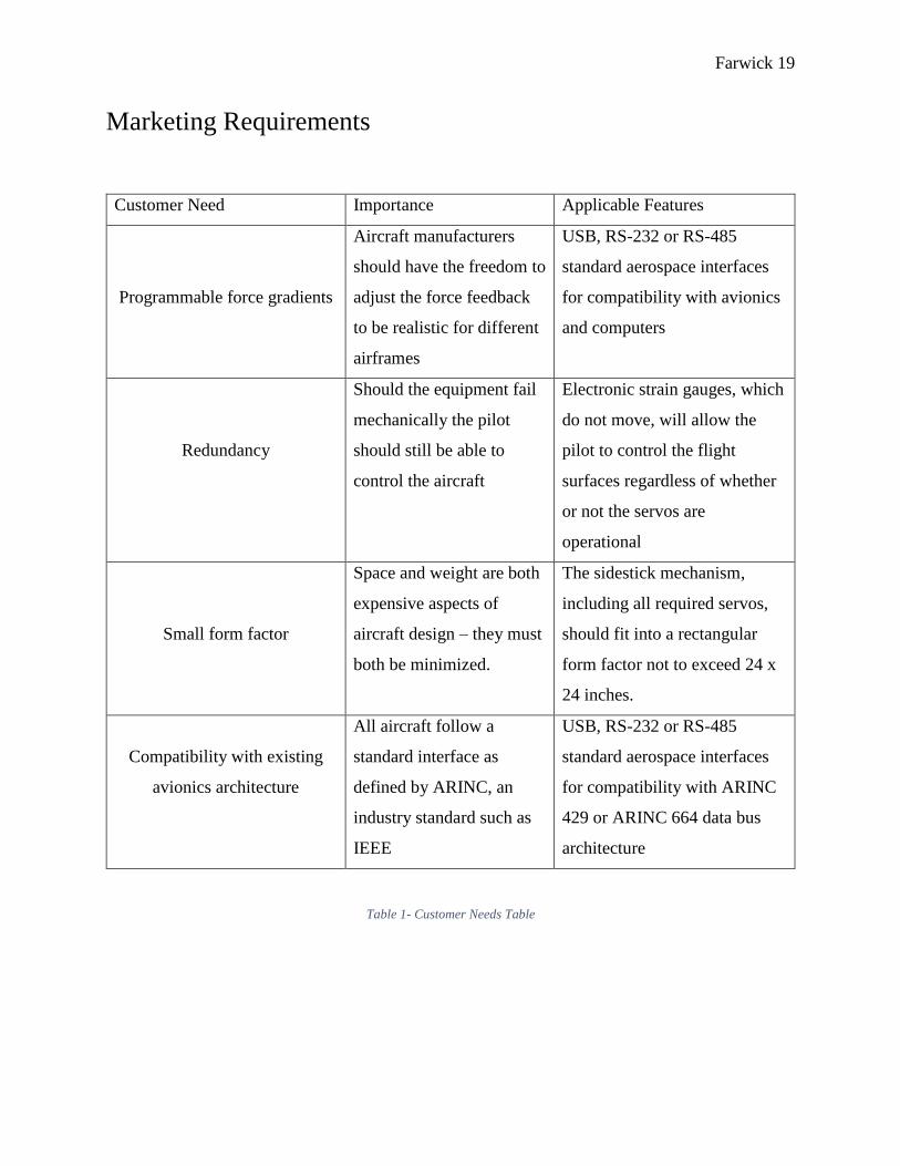
Customer Need Importance Applicable Features
Programmable force gradients
Aircraft manufacturers
should have the freedom to
adjust the force feedback
to be realistic for different
airframes
USB, RS-232 or RS-485
standard aerospace interfaces
for compatibility with avionics
and computers
Redundancy
Should the equipment fail
mechanically the pilot
should still be able to
control the aircraft
Electronic strain gauges, which
do not move, will allow the
pilot to control the flight
surfaces regardless of whether
or not the servos are
operational
Small form factor
Space and weight are both
expensive aspects of
aircraft design – they must
both be minimized.
The sidestick mechanism,
including all required servos,
should fit into a rectangular
form factor not to exceed 24 x
24 inches.
Compatibility with existing
avionics architecture
All aircraft follow a
standard interface as
defined by ARINC, an
industry standard such as
IEEE
USB, RS-232 or RS-485
standard aerospace interfaces
for compatibility with ARINC
429 or ARINC 664 data bus
architecture
Table 1- Customer Needs Table

Farwick 20
Programmable Force Gradients
With force feedback at the heart of the active sidestick technology it is important that this feature
be user programmable. User is defined in this context as a manufacturer, not a pilot. A jet
powered commercial airliner will clearly have different handling qualities than a smaller twin
piston engine aircraft. It is important that the active sidestick can then be adjust to have different
force responses or gradients depending on the aircraft type; for example, the sidestick should be
programmed to have a “heavier” feel in a large commercial airliner and a “lighter” feel in an
aircraft half the size which is more maneuverable. Electronic steering in automobiles is
analogous to this concept; a semi-truck with electronic steering should not be able to steer as
freely as a small automobile with the same technology.
Redundancy
A factor stressed in all aspects of avionics and aircraft development is common mode failure
avoidance and multiple redundancies. There should not be one point of failure that would result
in uncontrollability. The active sidestick is naturally redundant in that physical movement of the
stick is not required for electronic control of the flight surfaces; movement only serves the
purpose of force feedback. Multiple strain gauges will be used to sense force input such that
there are multiple channels to receive the pilot’s control input. In case of any failure, the pilot
will be alerted using a Crew Alerting Message (CAS) that is standard in large aircraft cockpits.
Small Form Factor
The active sidestick is going to be targeted for many different airframes which may vary from a
spacious cockpit to a much more compact cockpit. The final product must be designed to fit in
small spaces and not occupy valuable real estate in the cockpit. Aside from the size, weight is
also an important consideration in aircraft. The aircraft has a weight and balance calculation
accomplished anytime a modification is made that might vary the weight greater than a few
pounds. Greater weight also means higher fuel consumption and a high cost passed along to the
end customer.

Farwick 21
Avionics Backward Compatibility
The aerospace industry follows a standard set by Aeronautical Radio, Incorporated (ARINC)
when designing both avionics and human machine interfaces. Two common data bus standards
that the active sidestick will be required to interface with are ARINC 429 and ARINC 664 [8].
ARINC 429 is less complex and invokes a two-wire bus interface as depicted in the following
figure. Multiple units, such as the active sidestick, can communicate on the two-wire bus that
extends the entire aircraft.
Figure 5- ARINC 429 Bus Topology
ARINC 664 is more complex protocol that is like Ethernet; a unit is required for routing the
signals or assigning ports to line replaceable units (LRU). This method is becoming more
common in larger aircraft. The active sidestick should can interface with both data bus
architectures. A separate port should also be implemented to allow direct connection to a
computer.

Farwick 22
Figure 6- Marketing Data Sheet

Farwick 23
System Diagrams
Level 0 Diagram
Figure 7- Level 0 Black Box Diagram
Level 1 Diagram
Load Cells
ServoJoystick Gimbal
Assembly
Instrumentation Amplifier
Analog-DigitalConverter
Arduino
Teensy Joystick Emulator
Raw Voltage Amplified Voltage
Digital Force Input
Servo CommandsForce Feedback
X/Y Axis Potentiometer Data
USB to PC
Physical User Input
Simulator DataJoystick Control
HX711 IC

Farwick 24
Figure 8 – Level 1 System Diagram
User Input
The system receives physical user input directly from the joystick mechanism. The user force is
translated to an electrical signal using load cell sensors. The signals will require significant
conditioning and conversion to the digital domain further along in the system as can be seen in
the block diagram.
Joystick Control
One of the two outputs provided by the system is the joystick control. After sensing the user
input and comparing it with simulator data, the microcontroller will command a servo to drive
the movement of the joystick. In this sense, the user is not moving the joystick physically but
rather the microcontroller has full authority over its’ motion.
Simulator Data
The system will also require input data from an external flight simulator to provide realistic force
feedback to the user. This input is unique to the prototype of this system; in final release, the
simulator data would ideally be multiple inputs from the aircraft data bus.
USB to PC
The USB output is designed for interfacing with a PC. The PC will recognize the sidestick as a
human interface device (HID) similar to how a gaming joystick works. This will close the loop
between the flight simulator and sidestick system allowing full testing capability in flight
conditions that would not be safe in a real-world environment.

Farwick 25
Software Functional Diagram
Setup()
Instantiate servo class objects
Tare load cell readings
Center X/Y servos
Begin I2C Communications
Open serial port
Set pin modes
End Setup()
Loop()
Read X/Y potentiometer pins
Convert potentiometer data to degrees
Get load cell readings and convert to oz-in
Average load cell readings
Compute commanded servo position
Run PID algorithm
Instantiate PID class objects
Transmit potentiometer data to Teensyduino over
I2C
Retrieve serial data if available from the flight
simulator
End Loop()
Figure 9 - Software Flow Diagram

Farwick 26
System Requirements
Requirement I.D. Linked Market Requirement Engineering Requirement
1.0.0 User programmable force
gradients
The sidestick shall have
standard USB interface for
programming by PC
1.0.1 Simulator connectivity The sidestick software shall
be compatible with PC flight
simulators
1.1.0 Avionics backward
compatibility
The sidestick shall interface
at least with ARINC 429 data
bus topology
1.2.0 Redundancy The sidestick shall have full
controllability in the event of
servo or mechanical failure
1.2.1 Redundancy The sidestick shall
incorporate independent
power supplies for the servos
and logic devices in case of
faults
1.3.0 Small form factor The sidestick shall not exceed
a rectangular form factor of
size 24 x 24 x 24 inches
1.3.1 Small form factor The sidestick shall have a
grip that can be interchanged
for right or left handed
operation
Table 2 - Engineering Requirements

Farwick 27
System Design
Hardware Design
Load Cell
A dual axis load cell was required to measure the amount of force applied in both the x and y
axes. Designing such a load cell requires careful thought into the mechanical design such that
force is distributed across the structure correctly; furthermore, manual placement of strain gauges
on the load cell body requires great precision to allow the strain measurement of each axis to be
linear and repeatable. Rather than designing such a load cell from scratch, a readily available
load cell was chosen from the market. The M200 Dual Cantilever Load Cell by Strain
Measurement Devices was chosen for its small size and dual axis measurement ability. The
M200 is limited to 28 N-cm which limits its use in this application. To minimize the applied
torque a special grip was designed.
Figure 10 - SMD Sensors M200 Load Cell [9]
Strain Gauge Measurement
The full Wheatstone bridge configuration of the M200 load cell is not well suited for direct
measurement of resistance or differential voltage. With 10 VDC excitation voltage the datasheet
states the full scale output is 1.4 mV/V nominally. An excitation voltage of 5 VDC was chosen
for this application due to its availability from the microcontroller; at this voltage the full scale
output will be much less. To accurately measure and convert the differential voltage an
instrumentation amplifier and analog to digital converter is required. To minimize the possibility
of errors and noise from discrete components, the AVIA Semiconductor HX711 integrated

Farwick 28
circuit was chosen. The HX711 incorporates a 24-bit sigma delta ADC and programmable gain
amplifier.
Figure 11- HX711 Schematic [10]
SparkFun Electronics breakout board for the HX711 was purchased to speed the integration of
the HX711. The breakout board also incorporates filtering of the digital power rail to further
reduce noise susceptibility.
Gimbal Mechanism
A gimbal must be used to provide two degrees of freedom; the gimbal must also allow
attachment of one servo and potentiometer for each axis. Without the use of complex gear boxes
the most common gimbals on the market would not work for this application. The final gimbal
design was adapted from examining several joystick gimbal mechanisms widely available on the
market. The gimbal was completely designed in Blender 3D freeware software. The entire
gimbal is made up of three moving parts; two of which have 8mm shafts for the direct
attachment of a servo and potentiometer on opposite ends.
Figure 12 – Gimbal 3D Model

Farwick 29
Due to the complexity of the gimbal it was manufactured using 3D printing. The printed model
then had 8mm bearings attached to the shafts to allow smooth rotation on both axes.
Figure 13 - 3D Printed Gimbal Assembly
Figure 14 - Mounted Gimbal
Sidestick Grip
The M200 load cell has a 28 N-cm maximum force specification and 200% overload. To reduce
the amount of force applied to the load cell the grip had to be designed to focus the force at the
tip of the load cell. The grip was made in two pieces; when separated, the load cell can be placed
directly inside the grip. The 4mm shaft of the load cell is inserted into the grip which directs all
the force to the tip of the load cell.

Farwick 30
Figure 15 - Grip 3D Model
Figure 16 - 3D Printed Grip with Load Cell Attached
Servos
The servos for both the X and Y axes had to be selected to withstand the force applied by the
pilot along with additional torque required for force feedback. Provided the funding, there are
many DC servo motors on the market that could provide over 100 in-lb of torque to the gimbal
shaft. Given the financial limitations of this project, a suitable remote-control application servo
was chosen. The Savox SA-1283SG steel gear servo can provide up to 347.2 oz-in of torque at a
supply voltage of 4.7V. The digital servo is operated by the microcontroller using pulse width
modulation.
Figure 17 - Savox SA-1283SG Servo [11]

Farwick 31
USB Human Interface Device (HID)
To complete the loop between the flight simulator and sidestick the system required a USB
output to the PC that could act as a joystick. Having the primary microcontroller connect to the
PC and send joystick commands would hamper the fast processing speed required for the control
algorithm. To offload this process from the microcontroller the TeensyDuino 3.2 was selected to
be used solely as a joystick input for the PC. TeensyDuino can be programmed to present itself
as a human interface device (HID) to the PC when connected via USB. It will read in the
potentiometer voltages and scale the digitally converted data. For the X and Y axes, the PC
recognizes an integer value of 1024 as max deflection; thus, the potentiometer readings will be
calibrated to provide full scale deflection for the useable X and Y ranges of the gimbal.
Figure 18 - TeensyDuino 3.2 [12]
Microcontroller
The Arduino Mega 2560 was chosen as the primary microcontroller for the entire system. This
board is based on the Atmel ATmega2560 microcontroller. It was primarily chosen for the
number of analog inputs available. There are 54 digital I/O pins and 16 analog I/O pins. A 16
MHz onboard oscillator will be sufficient to handle serial communications and servo control at a
rate that will not create a noticeable lag to the user.

Farwick 32
Prototype Board
A prototype board was developed as an Arduino shield. The board connects the two HX711
devices, load cell Wheatstone bridges, potentiometers, servos and DC power supply to the
Arduino using header pins. Future improvements would be a PCB that incorporates all of the
devices.
Figure 19 - Prototype Board (Top)
Figure 20 - Prototype Board (Bottom)
Windows User GUI
Lockheed Martin Prepar3D® Interface
The flight simulator of choice for this project, Prepar3D®, has an interface library provided by
Lockheed Martin. The library, SimConnect, allows third party software to read flight simulation
variables or command the flight simulator directly. SimConnect is used in this project to gather
the flight simulation variables for transmission to the Arduino. Internal flight simulation
variables must be subscribed to before they can be requested by external applications. For this
project, the aircraft altitude, airspeed and barometer are requested. SimConnect allows a data
query at a 6 Hz rate which will limit the speed at which the data can be transmitted to the
Arduino.

Farwick 33
Arduino Serial Communication
Two-way communication with the Arduino and simulator host PC is required for sending flight
simulation variables and debugging information. Serial communication is established with the
Arduino by opening the COM port that the Arduino is associated with. A list of possible COM
ports is provided to the user. A timer is attached to the GUI to initiate a serial transmission every
170ms, or just below 6 Hz. This is to allow the flight simulation variables to refresh before every
transmission which occurs at a 6 Hz rate as defined in the SimConnect library. The data is then
packed into a string and sent over the serial connection. If serial data is received from the
Arduino, the data will be processed in the reverse manner.
GUI Functionality and Layout
The GUI allows the user to establish communication with the Arduino and simulator
independently. The individual fields are described in Table 3.
Field Name Options Description
P3D Connection Connect Connect to Prepar3D
Disconnect Disconnect from Prepar3D
Arduino Connection Connect Connect to the Arduino
Disconnect Disconnect from the Arduino
COM Port COM port for communication
with Arduino
Available Ports List of currently available
COM ports
Data Altitude Aircraft altitude above sea
level
Airspeed Aircraft true airspeed
Baro Kohlsman Barometer Setting
Joystick Sliders Displays the X and Y joystick
deflection value
Red Square Moves per the commanded
joystick movement
Table 3 - GUI Interface Description

Farwick 34
Figure 21 - Windows User GUI
Force Feedback Concept
With force as the input to the system a relationship is required to translate force to commanded
servo position. An initial relation was defined by the following equation:
𝑆𝑒𝑟𝑣𝑜 𝑃𝑜𝑠𝑖𝑡𝑖𝑜𝑛 = √𝐹𝑜𝑟𝑐𝑒 [𝑜𝑧 − 𝑖𝑛]
𝐾𝐺 [°]
𝐾𝐺 = 𝐹𝑜𝑟𝑐𝑒 𝐺𝑟𝑎𝑑𝑖𝑒𝑛𝑡 𝐶𝑜𝑛𝑠𝑡𝑎𝑛𝑡
Equation 1 - Force and Position Relation
The force gradient constant, KG, was selected such that a maximum applied force of 150 oz-in
would produce the maximum servo displacement of 25°. Servo position is considered as
displacement from the center position. The relationship was plotted in Figure 22. It can be seen
that only a small amount of force is required to increase the servo displacement from center. As
the servo position moves further from center it requires much more force to continue to the
movement. Three data sets were plotted with KG = 0.24, 0.34 and 0.14. A larger KG increases the
amount of force required to move the servo from the center position.

Farwick 35
Figure 22 - Servo Position vs Force Graph
The force constant will be varied in response to changing flight variables. For example, during
slow flight the force needed to move the stick should be minimal to mimic the sluggish response
of traditional flight controls. At the other extreme, high speed flight, the stick should be harder to
move because any large inputs to the flight controls will result in over controlling the aircraft.
Figure 23 depicts both scenarios graphically.

Farwick 36
Figure 23 - In-flight Force Feedback Visualization
Control System Design
A PID controller is required for both the X and Y axis servos attached to the gimbal assembly.
The feedback loop is provided by the potentiometers on each axis; each potentiometer has been
calibrated to provide a known voltage to position relationship. The microcontroller will read in
the feedback voltage and determine the corresponding position in degrees. The servo itself is
modeled as a second order system using the specifications provided in the datasheet. See the
Servo Characterization heading for information on how this was accomplished. The HX711
devices will be used to read in the current force being applied to each axis. This force is then
converted to an appropriate servo command in degrees. For information on this force to position
relationship see the heading Force Feedback Concept. Given that most of the control variables
are readily available as continuous, analog signals the control system would be well suited for a
completely analog PID controller. In this project, it was elected to perform all processes within
the microcontroller. A library was written for the microcontroller to perform the PID functions.
The library calculates the derivative, proportional and integral portions of the system and sums

Farwick 37
them for output to the servos. A simplified software flow diagram for the PID library is shown in
Figure 24.
PID::Calculate()
PID::Derivative()PID::Proportional()
PID::Integral()
Sum P, I, D values to create final output signal
Return
PID::Derivative()
Multiply error signal by KD
Copy result to private class variable
Return
PID::Proportional()
Calculate difference between command and feedback values
Multiply result by KP
Copy result to private class variable
Return
PID::Integral()
Multiply error signal by KI
Add result to accumulator
Copy accumulator value to private class variable
Return
Calculate and store error value in array
Figure 24 - PID Software Flow Diagram
To approximate the derivative and integration functions within the PID library the following
equations were used.
𝑑
𝑑𝑡𝑒[𝑛] ≈
∆𝐸𝑟𝑟𝑜𝑟
∆𝑇𝑖𝑚𝑒≈ 𝑇𝑆𝑎𝑚𝑝𝑙𝑒×(𝑒[𝑛] − 𝑒[𝑛 − 1])
Equation 2 - Approximate Derivative Equation
∫ 𝑒[𝑛] = ∑ 𝑒[𝑛] ×𝑇𝑆𝑎𝑚𝑝𝑙𝑒
Equation 3 - Approximate Integral Equation
A high-level diagram of the control system is shown in Figure 25. The signal flow from the load
cell to the servos and the feedback loop are illustrated. The simulated system in Matlab is
described in further detail under Simulink System Model.

Farwick 38
Figure 25 - Control System Diagram

Farwick 39
System Component Characterization
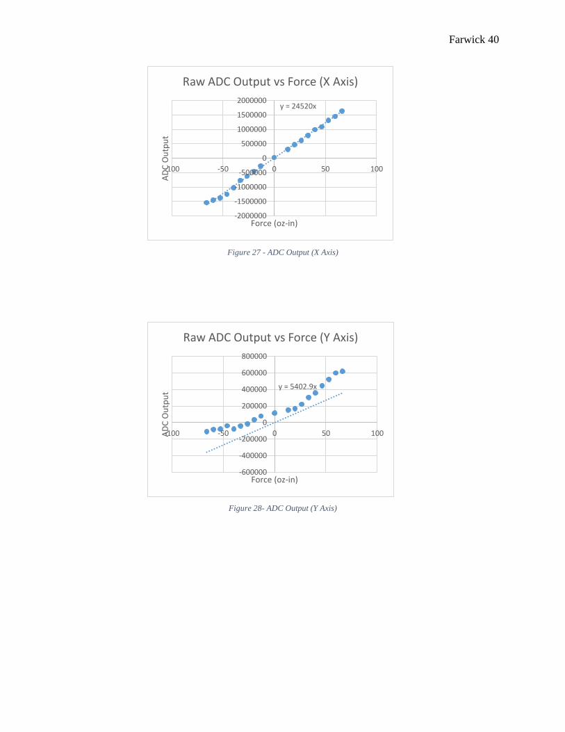
Load Cell Characterization
Before the load cell could be used it had to be tested for linearity and response to applied force.
Linearity is important to this application; without a repeatable and linear response, a control
algorithm would be difficult to implement. To test the load cell a fish scale was used to apply
force at defined intervals while measuring the differential voltage from the Wheatstone bridge as
well as raw ADC output. Both axes of the load cell were found to be linear and accurate; each
axis had a different slope of millivolt per unit force which will be taken into account with the
control algorithm.
Figure 26 - Test Setup for Load Cell
Farwick 40
Figure 27 - ADC Output (X Axis)
Figure 28- ADC Output (Y Axis)
y = 24520x
-2000000
-1500000
-1000000
-500000
0
500000
1000000
1500000
2000000
-100 -50 0 50 100A
DC
Ou
tpu
t
Force (oz-in)
Raw ADC Output vs Force (X Axis)
y = 5402.9x
-600000
-400000
-200000
0
200000
400000
600000
800000
-100 -50 0 50 100AD
C O
utp
ut
Force (oz-in)
Raw ADC Output vs Force (Y Axis)

Farwick 41
Figure 29 - Differential Voltage vs Force (Y Axis)
Figure 30 - Differential Voltage vs Force (X Axis)
Potentiometer Range Scaling
Before the potentiometers can be used for position sensing they must be calibrated to the range
of movement available from the gimbal. Each 10kΩ linear taper potentiometer was set to
approximately 5kΩ when each axis is centered. It is desired to translate the potentiometer
reading to degrees of displacement from the center position; to accomplish this, the ADC output
from each potentiometer was read at three different intervals – center position, full forward
deflection, full backward deflection. The displacement in degrees from center was read using a
protractor. Plotting the degrees of displacement per ADC output we can generate an equation to
y = 0.055x - 0.8928
-5
-4
-3
-2
-1
0
1
2
3
4
-100 -50 0 50 100D
iffe
ren
tial
Vo
ltag
e (m
V)
Force (oz-in)
Y Axis Differential Voltage vs Force
y = 0.0902x
-8
-6
-4
-2
0
2
4
6
8
-100 -50 0 50 100
Dif
fere
nti
al V
olt
age
(mV
)
Force (oz-in)
X Axis Differential Voltage vs Force

Farwick 42
translate the ADC output to a position in degrees. The position sensing serves a secondary
purpose as joystick commands to the flight simulator host PC. A full-scale deflection for any
joystick axis corresponds to 1024 and a center value of 512. With this information, we are also
able to determine a relationship to translate potentiometer ADC readings to digital joystick
position. The following readings were taken to accomplish both tasks:
Y Axis
ADC Reading Degrees of Displacement Joystick Position
891 65 1024
668 0 512
430 -65 0
X Axis
ADC Reading Degrees of Displacement Joystick Position
895 50 1024
800 0 512
536 -50 0
Table 4- Potentiometer Calibration Data

Farwick 43
Figure 31 - Potentiometer ADC Output (X Axis)
Figure 32 - Potentiometer ADC Output (Y Axis)
𝑌 𝐴𝑥𝑖𝑠 𝐷𝑖𝑠𝑝𝑙𝑎𝑐𝑒𝑚𝑒𝑛𝑡 = 0.2819𝑥 − 186.9 [ ° ]
𝑋 𝐴𝑥𝑖𝑠 𝐷𝑖𝑠𝑝𝑙𝑎𝑐𝑒𝑚𝑒𝑛𝑡 = 0.2594𝑥 − 192.9 [ ° ]
𝑌 𝐴𝑥𝑖𝑠 𝐽𝑜𝑦𝑠𝑡𝑖𝑐𝑘 𝑃𝑜𝑠𝑖𝑡𝑖𝑜𝑛 = 2.205𝑥 − 960.17 [𝐼𝑛𝑡𝑒𝑔𝑒𝑟]
𝑋 𝐴𝑥𝑖𝑠 𝐽𝑜𝑦𝑠𝑡𝑖𝑐𝑘 𝑃𝑜𝑠𝑖𝑡𝑖𝑜𝑛 = 2.6562𝑥 − 1463.3 [𝐼𝑛𝑡𝑒𝑔𝑒𝑟]
Equation 4 - Potentiometer Translation Equations
y = 0.2594x - 192.9
-100
-50
0
50
100
0 200 400 600 800 1000D
isp
lace
men
t (
°)
ADC Output
Potentiometer ADC Output vs Displacement (X Axis)
y = 0.2819x - 186.9
-100
-50
0
50
100
0 200 400 600 800 1000
Dis
pla
cem
ent
( °
)
ADC Output
Potentiometer ADC Output vs Displacement (Y Axis)

Farwick 44
Servo Characterization
To aid in the design of a PID controller for this system the transfer function of the servos must be
known. Referring to the datasheet of the Savox SA-1283SG servo it is known that the servo
response time is 0.16 seconds / 60°. This specification can be rewritten in a more useful form as
375° / second. Using this information, it is assumed the servo will require 2.67ms to respond to a
1° step input. This results in a time domain unit step response as shown in Equation 5.
𝑔(𝑡) = 1 − 𝑒−415.697𝑡 [°]
Equation 5 - Servo Time Domain Unit Step Response
The real-time step response of the servo is plotted in Figure 33.
Figure 33 - Servo Time Domain Step Response
The Laplace transform of the time domain response was taken to come up with a transfer
function G(s) as shown in Equation 6.
𝐺(𝑠) = 415.697
𝑠 + 415.697
Equation 6 - Servo Transfer Function

Farwick 45
Control System Tuning and Simulation
Ziegler-Nichols Tuning Method
Tuning of the experimental PID controller was accomplished using the Ziegler-Nichols method.
Being that the PID control is implemented on the microcontroller, the discrete version of the
Ziegler-Nichols values was required. A discrete PID controller transfer function can be
represented by the following equation:
𝑇(𝑠) = 𝐾𝑃𝑒[𝑛] + 𝐾𝑖 ∑ 𝑒[𝑘]
𝑛
𝑘=0
+ 𝐾𝑑(𝑒[𝑛] − 𝑒[𝑛 − 1])
Equation 7 - Discrete PID Transfer Function [13]
Where KP, KD, KI are obtained using a combination of the sampling, integration and derivative
times. The first step in determining these constants is determining the KP value at which an
oscillation in the output is sustained. This value is referred to as KC and the period of oscillation
is PC. Both constants are then used to determine the integration period, Ti, and derivative period,
Td, as shown in Table 5.
Controller KP Ti Td
P 0.5KC - -
PD 0.65KC - 0.12PC
PI 0.45KC 0.85PC -
PID 0.65 KC 0.5PC 0.12PC
Table 5 - Ziegler-Nichols Values [13]
The KD and KI constants can then be calculated using the following equations:
𝐾𝑖 =𝐾𝑃𝑇
𝑇𝑖 𝐾𝑑 =
𝐾𝑃𝑇𝑑
𝑇 𝑇 = 𝑠𝑎𝑚𝑝𝑙𝑒 𝑝𝑒𝑟𝑖𝑜𝑑
Equation 8 - Ki and Kd Equations [13]
The control loop implemented on the microcontroller repeats at intervals of 86ms which is the
sampling period, T. The controller was modified to be P control only and KP was increased until
oscillation was sustained at which point the value was recorded as KC. The oscillatory response
is shown in Figure 34. This information was applied through the Ziegler-Nichols method to

Farwick 46
obtain the initial PID constants as shown in
Table 6.
Figure 34 - Experimental Oscillatory Response
Variables
𝑇 0.086 (s)
KC 0.43
PC 0.172 (s)
Ti 0.1462 (s)
Ki 0.1138
KP 0.1935
Table 6 – Experimentally Tuned PID Constants
After applying the new values of KP and Ki a stable response was obtained as shown in Figure
35.
84
85
86
87
88
89
90
91
92
93
94
0 0.5 1 1.5 2 2.5 3 3.5 4 4.5
Serv
o P
osi
tio
n (
°)
Time (s)
Oscillatory Response (P Control) Kp = 0.43 (Y Axis)

Farwick 47
Figure 35 - Experimentally Tuned PI Step Response
Simulink System Model
Figure 36 - Simulink Control System Model
In the Matlab simulated system, several math blocks were used to implement the force to degrees
of displacement translation. A varying force is applied to the system as a discrete sine wave; this
is to simulate the discrete steps in which force is sampled from the HX711 devices. The force is
then translated to degrees using previously defined Equation 1 - Force and Position Relation. The
resulting value, in degrees, becomes the set point for the PID controller.
88
89
90
91
92
93
94
95
0 0.5 1 1.5 2 2.5 3 3.5 4
Serv
o P
osi
tio
n (
°)
Time(s)
Tuned Step Response (PI Control) (Y Axis)
Measured Step Response Poly. (Measured Step Response)

Farwick 48
Figure 37 - Simulink Model (Part 1)
A discrete PID controller is placed in the forward path of the control system. The sampling
period of 86ms from the microcontroller is used for this PID. The servo transfer function, as
previously defined, is also placed in the forward path. The output is in units of degrees.
Figure 38 - Simulink Model (Part 2)
The PID block was initially given the KP and Ki parameters discovered experimentally to
observe the response as shown in Figure 39. The commanded position is in blue, and the actual
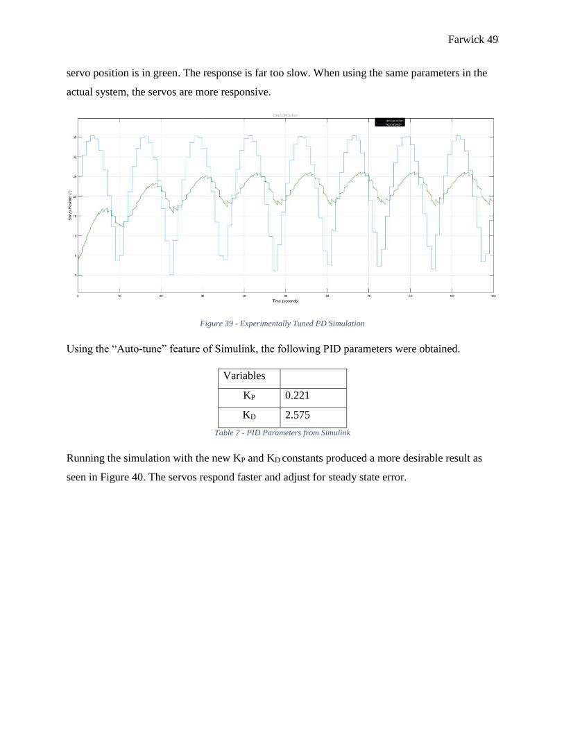
Farwick 49
servo position is in green. The response is far too slow. When using the same parameters in the
actual system, the servos are more responsive.
Figure 39 - Experimentally Tuned PD Simulation
Using the “Auto-tune” feature of Simulink, the following PID parameters were obtained.
Variables
KP 0.221
KD 2.575
Table 7 - PID Parameters from Simulink
Running the simulation with the new KP and KD constants produced a more desirable result as
seen in Figure 40. The servos respond faster and adjust for steady state error.

Farwick 50
Figure 40 - Simulink Tuned PD Control Simulation
To observe the effect of a varying force gradient constant, KG, a custom waveform that varied
from 0.24 to 0.75 was applied to the system. The varying KG could represent changing flight
variables of a real aircraft. As KG increased, it’s clear from the response that it requires more
force to move the servos. Likewise, a smaller KG means less force is required to move the servos
by the same amount. Figure 41 plots the servo movement, applied force, force gradient and
commanded servo position to better visualize the effect of a varying KG. It can be seen when KG
suddenly decreases, the servo displacement increases for the same amount of force.

Farwick 51
Figure 41 - Simulation of Varying Force Gradient
System Response
The PID constants determined from both the Ziegler-Nichols method and Simulink were applied
to the system to determine which set performed better.
The Simulink values shown in Table 7 produced oscillations greater than the servos could
handle. The KD constant was too large. For this reason, the PID constants were reverted to the
values shown in
Table 6.
To test the control system a sinusoidal force was applied to the grip while reading out the
commanded position, PID controller output and time. The commanded position is the value
calculated using Equation 1.
The system response with the values of
Table 6 is shown in Figure 42. It is obvious that the PID output significantly lags the
instantaneous commanded position. While this is not the desired behavior, it is necessary for the
stability of the system. Introducing larger PID constants quickly results in wild oscillations
which will be seen in another figure. With KI set at 0.1138 there is still a small steady state error
visible. At maximum deflection, there is a 23 degree lag between the commanded position and
PID output.Figure 42 - System Response to Sinusoidal Input (Ziegler-Nichols)

Farwick 52
Figure 42 - System Response to Sinusoidal Input (Ziegler-Nichols)
The KP and KI values were adjusted further through trial and error to become 0.2 and 0.35
respectively. The new system response can be seen in Figure 43. There is still about a 17 degree
lag between the commanded position and PID output but the steady state error was reduced to
nearly zero.
Figure 43 - System Response to Sinusoidal Input (Adjusted Z-N)

Farwick 53
To demonstrate the instability caused by too large of a KI or KD constant, in the next test case the
KP and KI constants were changed to 0.2 and 1.1 respectively. The PID output begins to oscillate
at the peaks of the sinusoidal input. This oscillation can become violent enough that the servos
stop responding to commands. The response can be seen in Figure 44.
Figure 44 - System Response to Sinusoidal Input (Oscillatory)

Farwick 54
System Testing
Force Feedback Testing
Testing was conducted to verify the force and position relationship discussed under the heading
Force Feedback Concept. The testing was accomplished by reading out variables from the
Arduino over serial; the variables used were potentiometer position, force and commanded
position. The potentiometer position is the displacement of the axis from center in degrees. The
force is calibrated to ounce-inches. The commanded position is the result from applying
Equation 1.
Figure 45 shows the displacement of the X axis versus the applied force. The actual sidestick
movement exceeds that of the theoretically calculated position as defined by the force and
position relationship. This additional movement is largely due to the slop in the servos and non-
rigidity of the 3D printed structures. The servos did not meet the holding torque specifications as
listed in the datasheet. The plastic structures also were not nearly rigid enough for this
application.
Figure 45 - Experimental and Theoretical Force and Position Relation
0
10
20
30
40
50
60
0 20 40 60 80 100 120
Dis
pla
cem
ent(
°)
Force (oz-in)
Displacement vs Force (Kg = 0.1)
Experimental
Theoretical

Farwick 55
The next test was varying the force gradient constant to see if the force and position relationship
holds. Figure 46 plots the response of three different force gradient constants. The plot proves
that a lower force gradient constant results in much more displacement while a higher constant
has the opposite effect.
Figure 46 - Position vs Force with Varying Kg
0
10
20
30
40
50
60
0 20 40 60 80 100 120 140
Dis
pla
cem
ent(
°)
Force (oz-in)
Displacement vs Force
Kg = 0.75
Kg = 2.0
Kg = 0.1

Farwick 56
Overall System Test and Results
The active sidestick was tested against the requirements initially set for the project. The
requirement and corresponding test results are listed in Table 8.
System Requirement Tested Result
Varying force gradient constant based on flight
conditions
Yes Successful
The sidestick shall have standard USB interface for
programming by PC
Yes Successful
The sidestick software shall be compatible with PC
flight simulators
Yes Successful
The sidestick shall interface at least with ARINC 429
data bus topology
No To be incorporated in later
iterations.
The sidestick shall have full controllability in the event
of servo or mechanical failure
Yes Successful
The sidestick shall incorporate independent power
supplies for the servos and logic devices in case of
faults
Yes Successful
The sidestick shall not exceed a rectangular form factor
of size 24 x 24 x 24 inches
Yes Successful
The sidestick shall have a grip that can be interchanged
for right or left handed operation
Yes Successful
Table 8 - System Test Results

Farwick 57
Project Schedule
Timeline and Major Milestones
The following table presents major milestones in the project timeline. The schedule will be
further broken down into a Gantt chart.
Milestone Quarter Date
EE 460 Final Senior Project
Report Due
Fall 2016 November 28th, 2016
Design Review Winter 2017 February 13th, 2017
Mid-project Demonstration Winter 2017 March 13th, 2017
Final Project Demo Spring 2017 June 14th, 2017
EE Senior Project Expo Spring 2017 June 2nd, 2017
Table 9- Major Milestones
The project is of such complexity that it will be broken down into smaller portions for
demonstration purposes. Also, due to the complexity there are several risks to the proposed
project timeline that may be encountered. A few of the projected risks are:
1. Software development overhead for interaction between the hardware and connected PC
2. The complex gimbal mechanism will require machining or 3D printing and careful
assembly
3. The final step of integrating the DC servos and controller could be the most time-
consuming process and extend beyond the project expo date
To better identify the individual milestones and associated deliverables, a Gantt chart is provided
below.

Farwick 58
Figure 47 - Winter 2017 Schedule
Figure 48 - Spring 2017 Schedule

Farwick 59
Task Breakdown
The tasks shown in the Winter and Spring Gantt charts are further broken down in the following
table.
Task Deliverables Projected Due Date
1 o Purchase initial components required to
characterize the load cells
January 16th
2 o Develop analog sensing interface
o Implement analog-digital converter for use with
microcontroller
January 16th
3 o Develop load cell force curves to fully
characterize the response to user input force
February 6th
4 o Devise a linear equation to map force input to
sensor output
o Use USB debugger to continuously read out
X/Y force inputs
February 13th
5 o Design review with faculty advisor, Dr. Benson February 13th
6 o Write C code for microcontroller to emulate a
joystick human interface device (HID) over
USB
February 20th
7 o Using the developed HID interface, test the
sidestick control in the flight simulator software
environment
o Fine tune load cell calibration to provide
consistent and realistic control inputs in the
simulator
March 6th
8 o Prototype demonstration for faculty advisor, Dr.
Benson
March 13th
9 o Develop GUI based C++ application to interface
with the flight simulation software and gather
relevant flight data
April 3rd

Farwick 60
10 o Implement serial data transfer between the C++
software and microcontroller
o Microcontroller reads in flight variables and
outputs current state variables
April 10th
11 o Robustness testing of serial data link over USB
while flying in the flight simulator using the
sidestick as control input
April 10th
12 o Using the flight variables provided by the flight
simulator, augment the mapping of force input
to X/Y control position
o Define the effect of flight variables on the
control output
April 17th
13 o Integrate the microcontroller with the two DC
servos
o Purchase and configure DC power supply for
use with the servos
April 17th
14 o Develop C code library to allow simple position
control of the DC servos
o Test the reliability of position commands
April 24th
15 o Devise algorithm to map X/Y control output,
before flight simulator data augmentation, to DC
servo position commands
April 24th
16 o Build 3D model of gimbal mechanism and
sidestick chassis
o 3D print the model and assemble parts
May 8th
17 o Build upon previous algorithm to augment the
DC servo commands with flight simulator data
May 15th
18 o Make final adjustments to all algorithms to
ensure smoothness of DC servo control and
realistic flight control responses in the simulator
May 15th

Farwick 61
19 o Perform final assembly of all components
integrated into the sidestick chassis and gimbal
May 22nd
20 o Final project demonstration for faculty advisor,
Dr. Benson
May 22nd
21 o EE Senior Project Expo June 2nd
Costs and Resources
If the manufacturing of the ActivSense Sidestick were to go live funding for materials, research,
design and manufacturing would be sought from industry partners and investors. Funding for the
senior project will come from Cal Poly’s Electrical Engineering department as well as the
Autonomous Flight Lab.
Table 10 - Bill of Materials

Farwick 62
Required Skills
Successful completion of this project will require skills in all areas of electrical engineering as
well as a deeper understanding of C/C++ software development. Sensing, analyzing and
converting the load cell signals to the digital domain will require a mix of analog and digital
electronics. The force feedback and DC servo loop will also require heavy use of control system
theory. Communications between the flight simulation software and the sidestick will require
extensive programming to define a protocol that converts the flight simulator program data into
something useable by the sidestick microcontroller.

Farwick 63
Conclusion and Future Improvements
Many different design choices would have been made if greater funding was available for this
project. Aerospace products are inherently more expensive than other industries due to the higher
quality of materials and additional design and testing that goes into any given product.
Given the limitations of a project with very little funding the sidestick was successful as a proof
of concept.
Mechanical Assemblies
One of the most limiting components of the design is the gimbal mechanism. Having a complex
structure, it was most cost effective to manufacture it through 3D printing with standard ABS
plastic. The plastic had very poor rigidity which allowed the structure to flex when force was
applied to the stick. A future design would be made such that it could be machined out of
aluminum or similar metals using CNC machine processes.
Servo
The use of a high torque RC servo is not viable for a production product at all; it was chosen
primarily due to the cost limitations. The servo was found to have virtually zero holding torque
when it is in the process of moving to a new position. This is a problem for this design as the
servos are almost always adjusting position to match user input to the stick. They also did not
hold up to the rated torque. Future iterations would make use of electric hydraulic or DC worm
gear servos. A worm gear motor would provide enough holding torque to prevent any damage to
the DC motor; it would also reduce the wear and tear on the motor caused by locked rotor
conditions.
Load Cell
The SMD M200 load cell had excellent accuracy when it comes to providing consistent,
calibrated force readings. The maximum torque rating was not sufficient for this application
which likely caused greater hysteresis over its period of use in this project. The best approach
would be incorporating strain gauges directly into the stem of the sidestick grip; this was not the
best approach for this project due to the precision required to correctly mount the strain gauges.
The 30 gauge leads on the load cell were very brittle and had to be soldered back on after
breaking off with the slightest movement.

Farwick 64
Microcontroller
The primary limitation related to the microcontroller is the speed at which the control algorithm,
to include the PID controller, could be run. The MCU was required to read both analog and
digital data from the potentiometers and HX711 devices respectively. This processing added to
the overall time required to complete one loop. Communication between the MCU and flight
simulation PC also held up the control loop whenever data was sent or received. An MCU
capable of threading would be a better fit for future iterations. An FPGA running multiple state
machines simultaneously would also be a possibility.
Additional Software
As the project advances the communication between the active sidestick and flight simulation PC
should be optimized. A standard message format should be defined to allow expansion for future
data types not thought of at this point. Ideally the active sidestick would communicate using one
of the standard ARINC protocols as described under Avionics Backward Compatibility.

Farwick 65
Analysis of Senior Project
Summary of Functional Requirements
The ActivSense Sidestick will transform user force input into flight control outputs. The
sidestick will be able to operate in manual mode which linearly maps force input to flight
controls. During full operation, the sidestick will interpret flight variables and adjust the flight
control output in a well-defined manner. End users will be able to modify the force gradients to
accommodate any type of aircraft.
Primary Constraints
The primary constraint and challenge of this project will be the integration of the DC servo
motors. Due to the number of variables present during aircraft flight a control system could be
another project itself alone. The servo control system is expected to span 50% of the project
development timeline. Building the chassis will require parts in complex shapes that need to be
machined or 3D printed. Final assembly of the sidestick chassis with working servo motors will
come in the last days of the project timeline.
Economic Impact
Human Capital
Just in consideration of the development cycle of the sidestick product hundreds of jobs will be
either supported or created. The primary source of employment will occur in the machining and
manufacturing phase of the development and final product roll out. Engineering will account for
the smallest percentage of the supported workforce. Beyond manufacturing of the product itself,
the manufacturers of individual components used in the design will also employ hundreds of
workers. With several components sourced outside of the United States, many countries will
benefit from the production.
Financial Capital
The sidestick is designed to target smaller businesses, as well as the large defense companies,
that would normally not be able to afford active sidestick technology. The sidestick could result
in weight savings in many types of aircraft which would also save manufacturers money over a
longer period. Introducing a viable sidestick alternative in the market will also promote

Farwick 66
competition in the industry and ultimately reduce the cost of the technology while making it
available to all businesses.
Natural Capital
The sidestick will be manufactured using many different types of materials. The chassis may first
be built using hardened plastic while a final product would be built of more durable material
such as aluminum. Individual electronic components will be carefully chosen to include only
RoHS compliant devices. At the end of life, the sidestick will most likely be recycled in the same
facility that processes retired aircraft. Training will be provided by the company to ensure all
components of the sidestick are properly recycled.
Costs and Timing
The market price of the product is expected to compete with current alternatives available. There
are no prices listed on the competitor websites but it can be estimated based on the aircraft that
currently make use of the active sidestick technology. An example would be the Gulfstream
G500 which is priced at over $75M. It is reasonable to expect the competition to price the
sidesticks around $30-40k per unit. The final version of the ActivSense sidestick will include
aerospace grade materials and be subject to intense testing to meet FAA standards. Without a
thorough understanding of the materials and testing involved it is difficult to estimate the final
price of the product. The goal is to keep the price to the customer below $15,000. A prototype
cost estimate is provided in the previous section titled Costs and Resources.
Manufacturability
If manufactured on a commercial basis:
a. An estimated 10-15 units will be sold in the first year.
b. The total cost of the prototype is roughly $369 as detailed in the Costs and Resources
section.
c. Final manufacturing and testing expenses will increase the market price exponentially to
about $15,000.
d. Estimated annual profit of $180,000
e. The operational costs for the end user will be primarily in annual inspections and
software updates. Mechanical failures should not occur within the lifetime of the

Farwick 67
airframe. Lifetime software updates are expected to be included with the purchase of a
sidestick unit. Annual maintenance costs shall not exceed $500.
Environmental Impact
a. What environment impacts are associated with manufacturing or use of the sidestick?
The primary environmental impact will stem from the sourcing of electronics and
aerospace grade materials. The various alloys used to manufacture the sidestick chassis
will inevitably be sourced from mines in multiple countries. The impact of electronic
material will be minimized by the strict use of RoHS compliant electronics.
b. Which natural resources and ecosystem services does the project use (directly and
indirectly) improve or harm?
The most significant resources being used in the production of the sidestick are aluminum
alloys. The aluminum will most likely be derived from bauxite ore which is the main
source of aluminum for the world. Australia is the top producer of bauxite followed by
China, Brazil, India and Guinea. To reduce the impact of the sidestick production and use
on the environment a recycling program will be established. Proper disposal and
recycling of the aluminum parts, as well as electronics, will aid in reducing the electric
power required to produce aluminum.
c. How does the project impact other species?
The sidestick will be produced in the most efficient and environmentally conscious
method possible but there is still the chance other species will be impacted. It is possible
that the use of the sidestick will indirectly affect other species based on what operations
the sidestick might support (Aerial strikes by drones, agricultural pesticide spraying
aircraft, etc).

Farwick 68
Sustainability
a. Describe any issues or challenges associated with maintaining the completed device.
The most significant challenge will be continued software updates for all of the sidesticks
still in use. As the customer base grows, software maintenance will become the
business’s largest overhead. Backwards compatibility when new versions are released
will also be important to the sustained operations.
b. Describe how the product impacts the sustainable use of resources.
As described in previous sections, a recycling initiative will be set in place from the
beginning of the lifecycle. To increase overall sustainability, strict recycling procedures
of the metal and electronic components must be adhered to.
c. Describe any upgrades that would improve the design of the project.
An upgraded gimbal and chassis would reduce the overall size of the sidestick and allow
it to be used in many more applications. Mechanical expertise shall be sought to
continually improve the design by reducing the physical footprint.
d. Describe any issues or challenges associated with upgrading the design.
Most of the issues associated with upgrading the design would come in the form of
backwards compatibility with sidesticks already in use. Customers may feel entitled to a
free upgrade if new designs are released often. Care shall be taken to ensure each design
release encompasses enough changes to warrant the purchase of a new sidestick rather
than upgrading.
Ethical Implications
Briefly touched upon in previous sections, there are several ethical implications from the
production of the sidestick. The sidestick is being marketed almost exclusively for the aerospace
industry which means that it can end up supporting any number of aerial activities. Sidesticks
being used in the operation of military drones that carry out ballistic airstrikes is just one
example of ethical conflict.

Farwick 69
Health and Safety
The safety of end users is of paramount importance in the design of the sidestick. Increased
safety is the primary reason the sidestick is being developed to begin with. Safety of pilots and
passengers are expected to increase dramatically as the product is phased into commercial and
military aircraft. Health impacts will be minimal if not completely non-existent; the users will be
in direct contact with the plastics which will be thoroughly researched for any possible adverse
health effects.
Social and Political Implications
a. Social and political issues associated with design, manufacture and use.
Similar to the ethical implications, depending on the use of the sidestick there are many
social and political issues that could arise. International trade and relations are at the
highest tensions with the current problems faced in the Middle East. Use of the sidestick
in support of military activities could have significant political impacts as well as
unforeseen social implications.
b. Who does the project impact? Who are the direct and indirect stakeholders? How are they
affected?
The sidestick has a far-reaching impact in consideration of the numerous direct and
indirect stakeholders. Citizens of the countries that employ use of the sidestick in military
operations will be indirect stakeholders of the sidestick. In the commercial market,
passengers of airlines will also be direct stakeholders based on their desire for increased
safety in aircraft operations.

Farwick 70
Appendix
Schematics

Farwick 71
Figure 49 - Main Schematic
Code
#include "HX711.h"
#include <Wire.h>
#include <Servo.h>
#include "PIDuino.h"
// HX711.DOUT - pin #A1
// HX711.PD_SCK - pin #A0
// HX711.DOUT - pin #A3
// HX711.PD_SCK - pin #A2
// Arduino SCL = 21
// Arduino SDA = 20
// Teensy SCL = Pin 19
// Teensy SDA = Pin 18
// X Axis Potentiometer = A4
// Y Axis potentiometer = A5
// write(25) -> 200 ( 0 deg -> 160 deg)
// writemicro(1000) -> 4000 uS = 0 deg -> 160 deg
String incomingString[3] = ""; // string to hold incoming serial
unsigned long prevTime; // Holds previous time in milliseconds
unsigned long HZ60 = 16; // 60 Hz interval time in milliseconds
float alt, kohls, tas; // Floats to hold incoming data
bool newData = true; // Serial data updated?
float scale_xpos, // Raw x value from HX711
scale_ypos, // Raw y value from HX711
xavg, // Average x value from HX711
yavg; // Average y value from HX711
float xpos[5] = {0}; // Float array to hold previous x values
float ypos[5] = {0}; // Float array to hold previous y values
float x_cmd_avg[5] = {95,95,95,95,95};
float y_cmd_avg[5] = {100,100,100,100,100};
int sample = 0; // Sample number for averaging
int x_ozin_scale = 24520; // Scaling factor to produce oz-in values from HX711
int y_ozin_scale = 24520; // Scaling factor to produce oz-in values from HX711
int x_pot_value, // Raw X pot value from ADC
y_pot_value; // Raw Y pot value from ADC
double x_pos_deg,
y_pos_deg; // Y pot value converted to degrees of displacement
int x_pot_scale = 1; // Scaling factor to produce degrees for X axis
int y_pot_scale = 1; // Scaling factor to produce degrees for Y axis
double kp = 0.3;
double kd = 1;
double ki = 0;
double x_cmd,y_cmd;
double x_kg = 0.24; //Force gradient constant
double y_kg = 0.24;
double x_request;
double x_averaged;
double y_request;
double y_averaged;

Farwick 72
/* CLASSES */
HX711 scale_y(A1, A0); // Instantiate HX711 classes
HX711 scale_x(A3, A2); // parameter "gain" is ommited
Servo x_servo, y_servo;
PID y_pid(0.34,0.1,0);
PID x_pid(0.02,.20,0);
/* PINS */
int x_pot_pin = A4; //Connect X pot to A4
int y_pot_pin = A5; //Connect Y pot to A5
/* FUNCTION DECLARATIONS */
void float_to_bytes(float data);
void retrieveData(float* alt, float* kohls, float* tas);
void sendFloat(float f, float g);
/* SETUP */
void setup() {
Serial.begin(9600);
pinMode(A4, INPUT);
pinMode(A5, INPUT);
x_servo.attach(9); // attaches the servo on pin 2 to the x axis servo object
y_servo.attach(8); // attaches the servo on pin 2 to the x axis servo object
scale_x.tare(5); // reset the scale to 0
scale_y.tare(5); // reset the scale to 0
Wire.begin(); // Begin I2C communication with Teensy
x_servo.write(95); //Center servo to begin
y_servo.write(95); //Center servo to begin
delay(10);
}
/* LOOP */
void loop() {
analogReference(EXTERNAL);
unsigned long currentTime = millis(); //Grab current time
x_pot_value = analogRead(x_pot_pin)/x_pot_scale; //Grab current X pot value
y_pot_value = analogRead(y_pot_pin)/y_pot_scale; //Grab current Y pot value
x_pos_deg = (x_pot_value*0.2594-207)+95;
y_pos_deg = 100-(y_pot_value*0.2819-186.9); //(inverted to match
scale_xpos = scale_x.get_value()/x_ozin_scale; //Grab raw X value and scale to oz-in
scale_ypos = scale_y.get_value()/y_ozin_scale; //Grab raw Y value and scale to oz-in
xpos[sample] = scale_xpos; //Store X value for averaging
ypos[sample] = scale_ypos; //Store Y value for averaging
Wire.beginTransmission(0x20); //Open comms with Teensy (#8)
xavg = (xpos[4]+xpos[3]+xpos[2]+xpos[1]+xpos[0])/5; //Average X values
yavg = (ypos[4]+ypos[3]+ypos[2]+ypos[1]+ypos[0])/5;

Farwick 73
if (xpos[4] == 0); //wait until first complete average populates
else
{
if (xavg < 0)
{
x_request = 95 - sqrt(abs(xavg)/x_kg);
x_cmd_avg[sample] = x_request;
x_averaged = (x_cmd_avg[4]+x_cmd_avg[3]+x_cmd_avg[2]+x_cmd_avg[1]+x_cmd_avg[0])/5;
}
else
{
x_request = 95 + sqrt(abs(xavg)/x_kg);
x_cmd_avg[sample] = x_request;
x_averaged = (x_cmd_avg[4]+x_cmd_avg[3]+x_cmd_avg[2]+x_cmd_avg[1]+x_cmd_avg[0])/5;
}
x_pid.Calculate(x_pos_deg,&x_cmd,x_averaged);
Serial.println();
Serial.println(-x_cmd+95);
Serial.println();
x_servo.write(-x_cmd+95);
if (yavg < 0)
{
y_request = 100 - sqrt(abs(yavg)/y_kg);
y_cmd_avg[sample] = y_request;
y_averaged = (y_cmd_avg[4]+y_cmd_avg[3]+y_cmd_avg[2]+y_cmd_avg[1]+y_cmd_avg[0])/5;
}
else
{
y_request = 100 + sqrt(abs(yavg)/y_kg);
y_cmd_avg[sample] = y_request;
y_averaged = (y_cmd_avg[4]+y_cmd_avg[3]+y_cmd_avg[2]+y_cmd_avg[1]+y_cmd_avg[0])/5;
}
y_pid.Calculate(y_pos_deg,&y_cmd,y_averaged);
}
float_to_bytes(x_pot_value);
float_to_bytes(y_pot_value);
Wire.endTransmission();
if (Serial.available() != 0)
{
retrieveData(&alt,&kohls,&tas);
Serial.flush();
}
if (sample == 4) //Increment sample number for averaging
{
sample = 0;
}
else
{
sample++;
}

Farwick 74
}
/* FUNCTION DEFINITIONS */
/* Function: float_to_bytes
Description: Breaks a float into bytes and transmits over I2C
Inputs: float data
*/
void float_to_bytes(float data){
unsigned int i = 0;
for(i=0; i<4; i++)
{
Wire.write( *((unsigned char*)&data + i));
}
}
/* Function: retrieveData
Description: Grabs incoming serial data from the PC and stores it
Inputs: float alt, kohls, tas
*/
void retrieveData(float* alt, float* kohls, float* tas){
int count = 0;
while (Serial.available() > 0) {
int inChar = Serial.read();
if (inChar != '\n')
{
incomingString[count] += (char)inChar;
}
else
{
//const char *buf = incomingString[count].c_str();
switch (count)
{
case 0:
*alt = incomingString[count].toFloat();
break;
case 1:
*kohls = incomingString[count].toFloat();
break;
case 2:
*tas = incomingString[count].toFloat();
break;
default:
*alt = incomingString[0].toFloat();
break;
}
count++;
}
}
}
/* Function: sendFloat
Description: Sends two floats back to the PC over serial

Farwick 75
Inputs: float f, g
*/
void sendFloat(float f, float g){
byte * b = (byte *) &f;
byte * c = (byte *) &g;
Serial.print("f:");
//Serial.write(b,4);
Serial.write(b[0]);
Serial.write(b[1]);
Serial.write(b[2]);
Serial.write(b[3]);
Serial.write(c[0]);
Serial.write(c[1]);
Serial.write(c[2]);
Serial.write(c[3]);
Serial.print(68); //Send nonsense.. Else serial drops offline
Serial.flush();
return;
}
#if ARDUINO >= 100
#include "Arduino.h"
#else
#include "WProgram.h"
#endif
#include <PIDuino.h>
PID::PID(double Kp, double Ki, double Kd)
{
kp = Kp;
kd = Kd;
ki = Ki;
time[0] = 0;
cum_err = 0;
}
bool PID::Calculate(double feedback, double* output, double command)
{
PIDout = output;
PIDfeedback = feedback;
PIDcmd = command;
err_sig[1] = PIDcmd - PIDfeedback;
time[0] = time[1]; //Save previous time
time[1] = micros();
if (time[0] == 0) //Have we not filled the time array?
{
return false;
}

Farwick 76
PID::Derivative();
PID::Proportional();
PID::Integral();
*PIDout = P + I + D;
err_sig[0] = err_sig[1]; //Save error signal
}
bool PID::Derivative()
{
double deriv = ( (err_sig[1] - err_sig[0]) );// / ((time[1] -
time[0])/1000000) );
D = kd * deriv;
}
bool PID::Proportional()
{
double prop = ( PIDcmd - PIDfeedback );
P = prop*kp;
}
bool PID::Integral()
{
double integ = ( (err_sig[1] - err_sig[0]) );//*((time[1]-
time[0])/1000000) );
cum_err += integ;
I = ki*cum_err;
}
void PID::SetTunings(double Kp, double Ki, double Kd)
{
kp = Kp;
ki = Ki;
kd = Kd;
}

Farwick 77
References
[1] S. Pope, "Flying Magazine," 23 April 2014. [Online]. Available:
http://www.flyingmag.com/aircraft/jets/fly-by-wire-fact-versus-science-fiction. [Accessed
12 October 2016].
[2] B. J. Feder, "New York Times," 29 June 1988. [Online]. Available:
http://www.nytimes.com/1988/06/29/business/business-technology-the-a320-s-fly-by-wire-
system.html?pagewanted=all. [Accessed 12 October 2016].
[3] F. George, "Aviation Week," 21 October 2014. [Online]. Available:
http://aviationweek.com/nbaa2014/pilot-s-viewpoint-need-upgrade-active-sidesticks.
[Accessed 12 October 2016].
[4] B. Systems, "BAE Systems," [Online]. Available: http://www.baesystems-
ps.com/pdf/active_sticks.pdf. [Accessed 12 October 2016].
[5] Airbus, "Orders and Deliveries," 2016. [Online]. Available:
http://www.airbus.com/company/market/orders-deliveries/.
[6] Boeing, "Boeing Commercial Airplanes," 2014. [Online]. Available:
http://www.boeing.com/commercial/.
[7] "The Guardian," 3 August 2012. [Online]. Available:
https://www.theguardian.com/news/datablog/2012/aug/03/drone-stocks-by-country.
[Accessed 15 10 2016].
[8] ARINC, "ARINC Industry Activities," 26 October 2015. [Online]. Available:
http://aviation-ia.com/standards/ArincStandardsDevelopmentDocument_1015.pdf.
[Accessed 17 OCtober 2016].
[9] "Strain Measurement Devices," [Online]. Available: www.smdsensors.co.uk.
[10] A. Semiconductor. [Online]. Available:
http://www.aviaic.com/uploadfile/hx711_brief_en.pdf.
[11] "Savox," [Online]. Available:
http://www.savoxusa.com/Savox_SA1283SG_Digital_Servo_p/savsa1283sg.htm.
[12] "PJRC TeensyDuino," [Online]. Available: https://www.pjrc.com/store/teensy32.html.
[13] Atmel, "AVR221: Discrete PID Controller on tinyAVR and megaAVR Devices," Atmel
Corporation, San Jose, 2016.

Farwick 78
Related Documents