Welsh Government Active Travel Guidance February 2020 Image courtesy of Chandra Prasad / Sustrans

Welcome message from author
This document is posted to help you gain knowledge. Please leave a comment to let me know what you think about it! Share it to your friends and learn new things together.
Transcript
Welsh Government
Active Travel GuidanceFebruary 2020
Image courtesy of Chandra Prasad / Sustrans
2 Consultation Draft 2020
ContentsPART 1 - Delivery
Chapter 1: Part 1 Introduction 11
Chapter 2: Policy and Legislative Context 172.1 Introduction 172.2 Well-being of Future Generations Act 172.3 Environment (Wales) Act 2016 192.4 Programme for Government 192.5 Planning Policy Wales 202.6 Equalities 21 2.7 WelTAG 232.8 Sustainable Drainage 24 Chapter 3: The Duties on Local Authorities 25 3.1 The Duties under the Active Travel Act 253.2 Timescale for the Submission of the Active Travel Network Map 263.3 Where the Duties Apply 26
Chapter 4: Definitions 284.1 Definition of Active Travel and Active Travel Routes 284.2 Terminology 28 4.3 Definition of Active Traveller - walkers, cyclists and other highway users 28
Chapter 5: Planning the Network 315.1 Who the network is for? 315.2 Designated Localities 325.3 Crossing Administrative Boundaries 325.4 Rurality 325.5 Mapping the network 335.6 Prioritisation and Network Coverage 355.7 Preparing the Map 36
© Crown copyright 2020 WG40120Mae’r ddogfen yma hefyd ar gael yn Gymraeg / This document is also available in Welsh
3 Consultation Draft 2020
5.8 Planning Status 375.9 Routes that are not owned by a local authority 375.10 Training and Support 385.11 Approving the Map 385.12 Publishing the Map 385.13 Reviewing the Map 395.14 Partial Review of the Map 415.15 Continuous improvement 425.16 Funding the Network 42
Chapter 6: Consultation and Engagement 446.1 Preparation of the Map 44
Chapter 7: Promoting Active Travel 47
Chapter 8: Monitoring and Reporting 488.1 Reporting Duties 488.2 Review of the Act 48
Chapter 9: Provision for Walkers and Cyclists when Changes are Made to the Highway 499.1 Duties under the Act 499.2 Creation and Maintenance of the Highway 499.3 Interference with Highways 509.4 Acquisition of Land for Highway Purposes 509.5 Traffic Regulation and Traffic Regulation in Special Cases 519.6 Parking 519.7 Obstructions 519.8 Street Works 529.9 Traffic Management 52
4 Consultation Draft 2020
PART 2 - Planning and Design
Chapter 10: Part 2 Introduction 5510.1 Activ e Travel Wales 6310.2 Highway Desin and the Active Travel Act 6410.3 Status of the Guidance 6810.4 Trunk Roads 6810.5 Local Roads 6810.6 New Develoment 6910.7 Innovation and Experimentation 6910.8 Design Elements 6910.9 Keeping Standards Up to Date 70
Chapter 11: Stakeholder Participation, Engagement and Consultation 6311.1 Introduction 63 11.2 Principles of Good Practice 6311.3 Tools for Participation and Consultation 6611.4 Action Travel Network Map Consultation 6811.5 Scheme Delivery and Sultation 70
Chapter 12: User Needs 7212.1 Similarities and Differences 7212.2 Design Principles 7312.3 Inclusive Design 7312.4 Pedestrians’ Needs 7612.5 Widths for Pedestrian Routes 8112.6 Gradients for Pedestrian Routes 8312.7 Surface Material for Pedestrian Routes 8312.8 Reference for Pedestrian User Needs 8412.9 Cyclists’ Needs 8412.10 Why do People Cycle? 8512.11 Minimising the Effort Required to Cycle 8612.12 Dimensions of Cycles commonly in use 8912.13 Headroom for Cycle Routes 92

5 Consultation Draft 2020
12.14 Typical Cycling Speeds 9212.15 Visibility Dimensions for Cycle Routes 9312.16 Gradients on Cycle Routes 9412.17 Space required for Cycling 9512.18 Widths for Cycle Tracks 9612.19 Widths for Cycle Lanes 9712.20 Additional Width Adjacent to Vertical Features 9812.21 Width Considerations for On-Carriageway Cycling 9912.22 General Lane Widths on Carriageways 9912.23 Width at Pinch Points 10012.24 Surfaces for Cycle Routes 101
Chapter 13: Network Planning 10413.1 Introduction 104 13.2 Showing the Existing Routes on the Active Travel Network Map 10713.3 Showing Proposed Routes on the Active Travel Network Map 10713.4 Integration with Policies, Plans, Programmes and Infrastructure 10813.5 Network Planning for Walking 11013.6 Network Planning for Cycling 11713.7 Validation of Active Travel Network Maps 12813.8 Prepare and Submit Active Travel Network Map 12913.9 Prioritising and Delivering the Active Travel Schemes 129
Chapter 14: Design for Walking & Cycling 13314.1 Introduction 133 14.2 Co-Production of design 13414.3 General design considerations 13514.4 Basic Network 13714.5 General Design Approachs 13814.6 Reducing the Speed and Volume of Motor Vehicles 13914.7 Filtered Permeability 13914.8 Reallocation of road space 14014.9 Vehicle Restricted Areas 14114.10 Pedestrian prioritised and informal streets 14314.11 Link Design Considerations 144
6 Consultation Draft 2020
14.12 Segregration between Cyclists and Pedestrians DE023, DE024, DE032 and DE033 146
14.13 Type of segregation 14814.14 Monitoring and Management 15014.15 Pedestrians on Links - DE001, DE002, DE003 and DE004 15214.16 Gradients, Ramps and Steps 15414.17 Cycling on Links - Introduction 15214.18 Traffic Lane Widths and Car Parking 15414.19 Cycling in All-Purpose Traffic Lanes 15614.20 Reducing Traffic Volumes and Speeds DE005, DE006, DR007 15614.21 Contraflow Cycling DE009 and DE010 15714.22 Traffic Calming DE005, DE006 and DE007 15714.23 Quiet Streets DE011 159 14.24 Cycle Streets DE012 15914.25 Cycle Lanes DE009, DE013, DE014, DE015, DE016 and DE017 16014.26 Car parking / loading and Cycle Lanes DE015 161 14.27 Cycle Lanes at Side Roads DE016 16114.28 Removal of centre lines DE017 16114.29 Cycle lanes with light segregation DE018, DE019, DE020 16214.30 Stepped Cycle Tracks DE021 and DE022 16314.31 Cycle Tracks Alongside the Carriageway DE023 and DE024 16414.32 Cycle track crossing of side roads DE025 DE026 16514.33 Side Road Entry Treatments and Blended Junctions
DE039 and DE040 16714.34 Cycle tracks in centre of carriageway DE027 16814.35 Cycle Lanes/Tracks at Bus Stops DE028 DE029 DE030
DE031 17014.36 Cycle Tracks away from Roads DE032 and DE033 17214.37 Design and Construction of Routes away from the Highway 17314.38 Cycling on Rural Roads 17514.39 Transitions between Cycle Tracks and the Carriageway DE034 17714.40 Cyclists and public transport routes 17914.41 Bus lanes and bus-only streets DE035 18014.42 Cycling and Trams 18014.43 Crossing and Junction Design - General Principles 18114.44 Considerations for Pedestrian and Cycle Crossings 18314.45 Crossing Types 185
7 Consultation Draft 2020
14.46 Uncontrolled Crossings DE036 DE037, DE038, DE039 and DE040 18614.47 Central median strips DE041 18714.48 Zebra crossings DE042 18814.49 Signalised crossings away from junctions DE044 and DE045 18814.50 Crossings at signal-controlled junctions 18914.51 Cycle priority crossings DE037 19014.52 Simple uncontrolled crossings DE036 19114.53 Uncontrolled crossing with refuge DE038 19114.54 Parallel Crossing for Pedestrians and Cyclists DE043 19114.55 Signalised Cycle and Pedestrian Crossings (Toucan) DE045 19214.56 Pedestrian and Cycle Bridges DE046 19314.57 Subways and Underbridges DE047 19314.58 Wheeling Ramps DE048 19514.59 Cyclists at Priority Junctions 19514.60 Unmarked Informal Junctions DE048 19614.61 Signalised Junctions for Cyclists - General Considerations 19714.62 Advanced stop lines (ASLs) DE050 19814.63 Cycle signal stages 20014.64 Exemption from banned turns 20214.65 Intergreen Times 20214.66 Permanent green cycle signal on bus gate 20214.67 Diagonal cycle crossing stage during all red 20214.68 Cycle bypass at traffic signals DE051 20314.69 Uncontrolled cycle crossing at signalled junction 20514.70 Guiding cyclists through signalised junctions DE052 205 14.71 Two stage right turn at traffic signals DE053 20614.72 Hold the Left Turn DE054 20714.73 Simultaneous green signals DE055 20814.74 Trixi Mirrors (Blind spot mirrors) 20814.75 Cycle provision at signalised roundabouts 20914.76 Cycle Provision at Unsignalised Roundabouts 20914.77 Mini Roundabout DE056 21014.78 Compact (or “Continental”) roundabouts DE055 21114.79 Conventional Unsignalised Roundabouts 21214.80 Dutch Style Roundabout DE058 21314.81 Informal roundabouts at unmarked junctions 214
8 Consultation Draft 2020
Chapter 15: Integration with Public Transport 21715.1 Introduction 217 15.2 Improving Walking Access to Public Transport 21715.3 Improving Cycling Access to Public Transport 21815.4 Carriage of Cycles on Public Transport 21815.5 Cycle hubs and Services at interchanges 22115.6 Park and Cycle 223
Chapter 16: Street Furniture and Cycle Parking 22516.1 Introduction 22516.2 Seating 22616.3 Public toilets 22716.4 Signs for Pedestrians 22816.5 Planting and Hard Landscaping 23116.6 Litter Bins 23316.7 Cycle Count Displays 23416.8 Cycle Parking 23416.9 Signs for Cyclists 243
Chapter 17: Related Facilities 25017.1 Introduction 25017.2 General Processes for Highway Works 25017.3 Highways Created by Welsh Government and
Highway Authorities 25317.4 Highways Created by Private Sector Developments 25317.5 Highway Improvement Schemes 25617.6 Highway Maintenance Schemes 25717.7 Managing Highways 258
Chapter 18: Construction, Maintenance and Management 26218.1 Introduction 26218.2 On-carriageway cycle routes 26218.3 Coloured surfacing 26318.4 Footway construction 26318.5 Footpath construction 26318.6 Cycle Track Construction 264
9 Consultation Draft 2020
18.7 Tactile paving 26618.8 Kerbs, edgings and verges 26718.9 Drainage 23918.10 On-Carriageway Drainage 26918.11 Off-Carriageway Drainage 27018.12 Access Controls 27218.13 Fencing and Hedgerows 27318.14 Lighting 27418.15 Maintenance - Introduction 27518.16 Design with maintenance in mind 275 18.17 Maintenance Responsibilities 27618.18 Maintenance Tasks 27618.19 Bridges and other structures 27918.20 Winter Maintenance 27918.21 Highway Enforcement and Custodianship 280
Chapter 19: Cycle and Pedestrian Traffic at Streetworks and Construction Sites 28219.1 Maintaining Active Travel Routes at Streetworks 282 19.2 Issues for Users 28319.3 Principles for Managing Active Travel at Streetworks 28419.4 Traffic Lane Widths at Roadworks 28619.5 Temporary Speed Limits 287
Chapter 20: Monitoring and Evaluation 28820.1 Introduction 28820.2 Why Monitor and Evaluate? 28820.3 How to approach data gathering 28920.4 Data gathering tools 29020.5 Recommended Approach 29220.6 Analysing the data 29620.7 Output 297
Glossary 298
10 Consultation Draft 2020
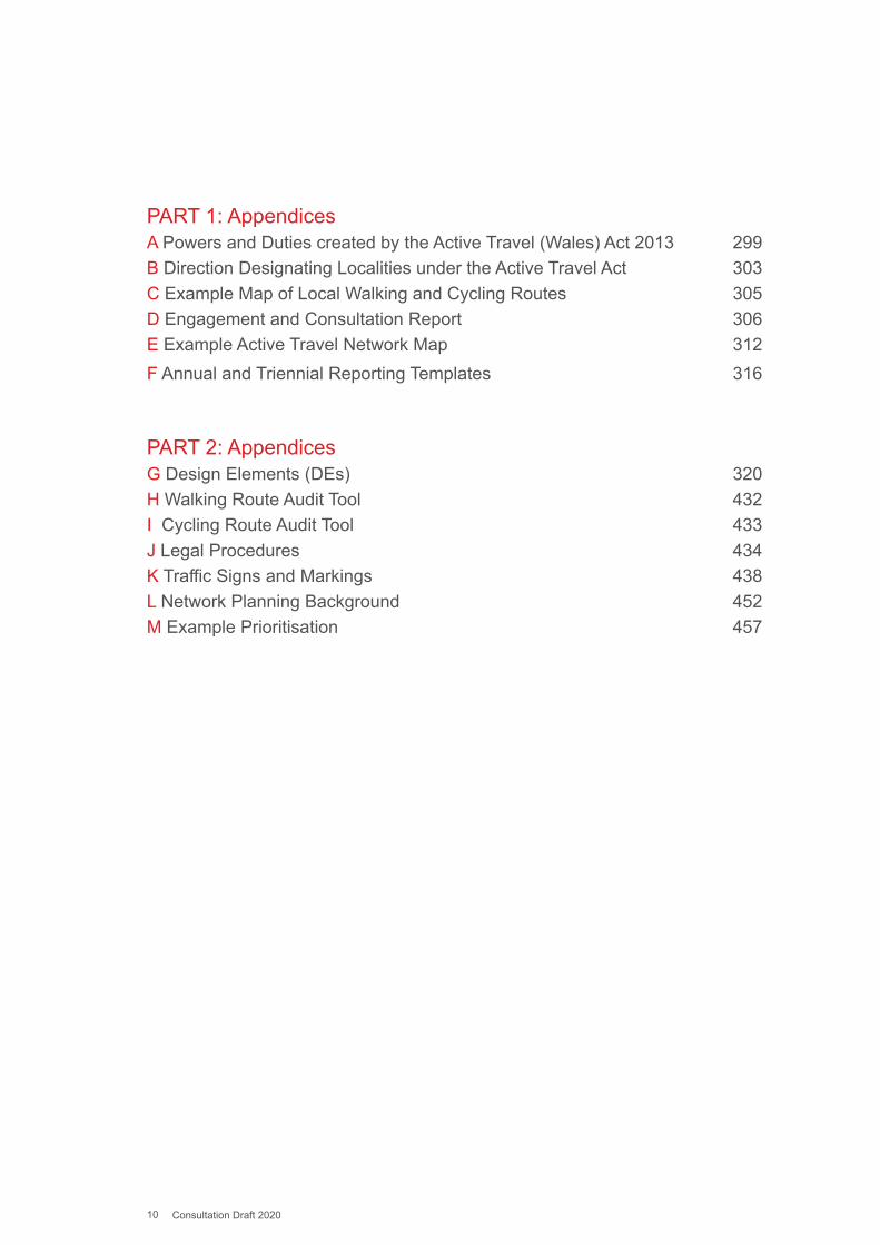
PART 1: AppendicesA Powers and Duties created by the Active Travel (Wales) Act 2013 299B Direction Designating Localities under the Active Travel Act 303 C Example Map of Local Walking and Cycling Routes 305D Engagement and Consultation Report 306 E Example Active Travel Network Map 312F Annual and Triennial Reporting Templates 316
PART 2: AppendicesG Design Elements (DEs) 320H Walking Route Audit Tool 432I Cycling Route Audit Tool 433J Legal Procedures 434K Traffic Signs and Markings 438L Network Planning Background 452M Example Prioritisation 457
Part 1: Planning and Design
11 Consultation Draft 2020
1.1.1 Active travel is a term used to describe walking and cycling for purposeful journeys. Whilst walking and cycling are in themselves healthy activities that are to be encouraged, it is when they displace car journeys that they deliver significant benefits for the health and well-being of Wales – increasing levels of active travel contributes to the achievement of all seven of Wales’ Well-being Goals. It was to reap these benefits that the National Assembly for Wales passed the Active Travel Act into legislation in 2013. The Act had the aim of making “walking and cycling the most natural and normal way of getting about”. When compared with many other European countries, levels of active travel in Wales are low. The provisions of the Act therefore do not, primarily, cater for existing active travellers. Rather, they put in place the conditions that will allow many more people whose current mode of travel is the car to switch to the more sustainable modes for shorter journeys and facilitate access to public transport as part of longer distance journeys.
1.1.2 The main barrier to more people taking up active travel is the perception of danger from motorised transport. Overcoming that perception is key to the success of the Act. Unless people can be persuaded that their journey - the entire journey - can be made safely by active travel, they will continue to use their cars. The number of active journeys people will make will depend on how comprehensive the network of safe routes is and how well the routes connect with each other.
1.1.3 The Act requires local authorities in Wales to produce maps of active travel networks that set out plans for these networks and to deliver year on year improvements in active travel routes and facilities. These routes are to be coherent, direct, safe, comfortable and attractive. As well as creating the infrastructure the Act includes provision for making people aware of the available and planned routes through the publication of the Maps and for the promotion of active travel as a means of transport. It requires highways authorities in Wales to make enhancements to routes and facilities for pedestrians and cyclists in all new road schemes and to have regard to the needs of walkers and cyclists in a range of other highway authority functions. The full text of the Act is available at:
www.legislation.gov.uk/anaw/2013/7/contents/enacted
Chapter 1: Introduction
Part 1: Planning and Design
12 Consultation Draft 2020
1.1.4 This edition of the Guidance has incorporated the Existing Routes Map and the Integrated Network Map, set out in the Act, into the new Active Travel Network Map (ATNM). See 5.5 for details.
1.1.5 This guidance is published by the Welsh Ministers under sections 3(4), 4(5), 5(2) and 7(2) of the Act. For ease of reference, throughout this document it will be known as Part 1: Delivery or ‘this guidance’.
1.1.6 Local authorities are required to have regard to the guidance when exercising the functions to which the guidance relates. All references within the guidance to local authorities are to be taken as references to county and county borough councils. The duties under the Act are placed on the local authority generally, rather than a specific part of the local authority. This guidance is therefore for all parts of the local authority, not just for the local authority in its capacity as the local highway authority. Part 1: Delivery is one part of the guidance issued under the Act. The other part is Part 2: Planning and Design, which provides essential, detailed, technical advice on how the infrastructure should be planned and designed. This first part of the guidance provides signposts to relevant chapters of both parts of the guidance as an aid for the various local authority personnel who will be involved in the implementation of the Act but who do not require all Part 2’s technical information on highway design. All personnel involved in highway planning and design will need to be familiar with both parts, but particularly with Part 2.
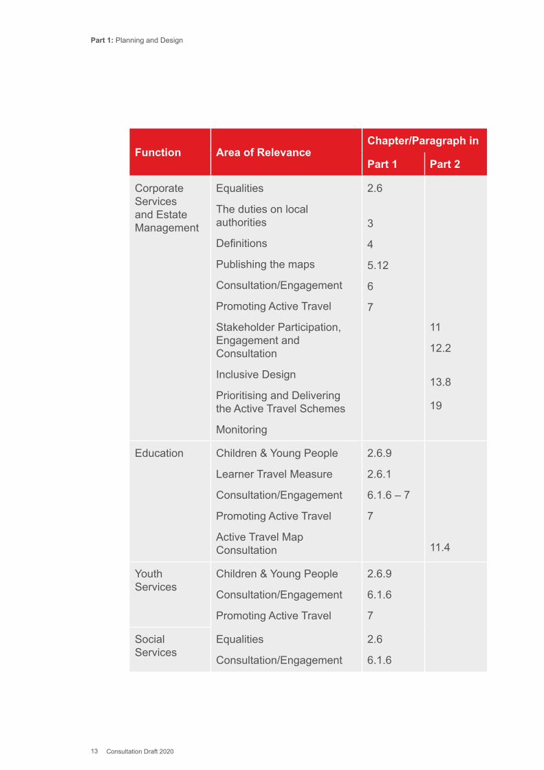
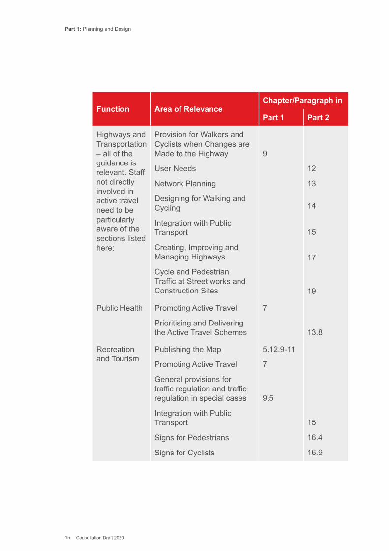
1.1.7 The effective implementation of a local authority’s duties under the Act will require effective collaboration amongst departments and a clear understanding of the responsibilities of each department. The chart below sets out which parts of the guidance are most relevant to which department. Given that the names local authorities give to the department carrying out a particular function varies from authority to authority it has not been possible to refer to specific departmental titles, the chart instead refers to generic functions. This chart also applies to Welsh Government.
Part 1: Planning and Design
13 Consultation Draft 2020
Function Area of RelevanceChapter/Paragraph in
Part 1 Part 2
Corporate Services and Estate Management
Equalities
The duties on local authorities
Definitions
Publishing the maps
Consultation/Engagement
Promoting Active Travel
Stakeholder Participation, Engagement and Consultation
Inclusive Design
Prioritising and Delivering the Active Travel Schemes
Monitoring
2.6
3
4
5.12
6
7
11
12.2
13.8
19
Education Children & Young People
Learner Travel Measure
Consultation/Engagement
Promoting Active Travel
Active Travel Map Consultation
2.6.9
2.6.1
6.1.6 – 7
7
11.4
Youth Services
Children & Young People
Consultation/Engagement
Promoting Active Travel
2.6.9
6.1.6
7
Social Services
Equalities
Consultation/Engagement
2.6
6.1.6

Part 1: Planning and Design
14 Consultation Draft 2020
Function Area of RelevanceChapter/Paragraph in
Part 1 Part 2
Planning, Growth and Regeneration
Planning Policy Wales
Planning status of the Active Travel Network Map
Funding the network – S106 and CIL
New Developments
Network Planning
Integration with Public Transport
Street Furniture and Cycle Parking
Construction, Maintenance and Management
2.5
5.8
5.16.4 – 6
10.6
13.4
15
16
18
Development Control and Conservation
Environment Act
Planning Policy Wales
Planning status of the Active Travel Network Map
Funding the network – S106 and CIL
New Developments
User Needs
Street Furniture and Cycle Parking
Construction, Maintenance and Management
2.3
2.
5.8
5.16.4 - 7
10.6
12
16
18
Environmental Health
User Needs 12
Part 1: Planning and Design
15 Consultation Draft 2020
Function Area of RelevanceChapter/Paragraph in
Part 1 Part 2
Highways and Transportation – all of the guidance is relevant. Staff not directly involved in active travel need to be particularly aware of the sections listed here:
Provision for Walkers and Cyclists when Changes are Made to the Highway
User Needs
Network Planning
Designing for Walking and Cycling
Integration with Public Transport
Creating, Improving and Managing Highways
Cycle and Pedestrian Traffic at Street works and Construction Sites
9
12
13
14
15
17
19
Public Health Promoting Active Travel
Prioritising and Delivering the Active Travel Schemes
7
13.8
Recreation and Tourism
Publishing the Map
Promoting Active Travel
General provisions for traffic regulation and traffic regulation in special cases
Integration with Public Transport
Signs for Pedestrians
Signs for Cyclists
5.12.9-11
7
9.5
15
16.4
16.9

Part 1: Planning and Design
16 Consultation Draft 2020
1.1.8 Parts of Part 1: Delivery will be of relevance to the Welsh Ministers, whoalso have duties under the Act, and other delivery partners.
1.1.9 This guidance will be reviewed and updated based upon feedback from local authorities of their experience of fulfilling their duties under the Act and the usefulness of this guidance in supporting them. Comments and views on this guidance can be sent to:

Part 1: Planning and Design
17 Consultation Draft 2020
2.1. Introduction2.1.1 This chapter outlines the various policies and legislation that impact on
the enabling and promotion of active travel in Wales. Advice about how other existing duties can be met whilst discharging duties under the Act is set out in relevant chapters of the guidance.
2.2. Well-being of Future Generations Act2.2.1 In 2015 Wales passed the Well-being of Future Generations Act to
enshrine Wales’ commitment to sustainable development in law. The Act applies to all devolved public bodies in Wales including Welsh Government and all local authorities. The Act put in place seven national goals and five ways of working.
2.2.2 Under the Act, public bodies now have a duty to use sustainable development to shape everything they do, how it is done, and how it is communicated (via reporting), to show how they are contributing to the achievement of the well-being goals.
Figure 2.1: The Goals of the Well-being of Future Generations Act
Chapter 2: Policy and Legislative Context
GloballyResponsible Prosperous
Healthier
More Equal
CohesiveCommunities
Vibrant Cultureand Thriving
Welsh LanguageResilient
Part 1: Planning and Design
18 Consultation Draft 2020
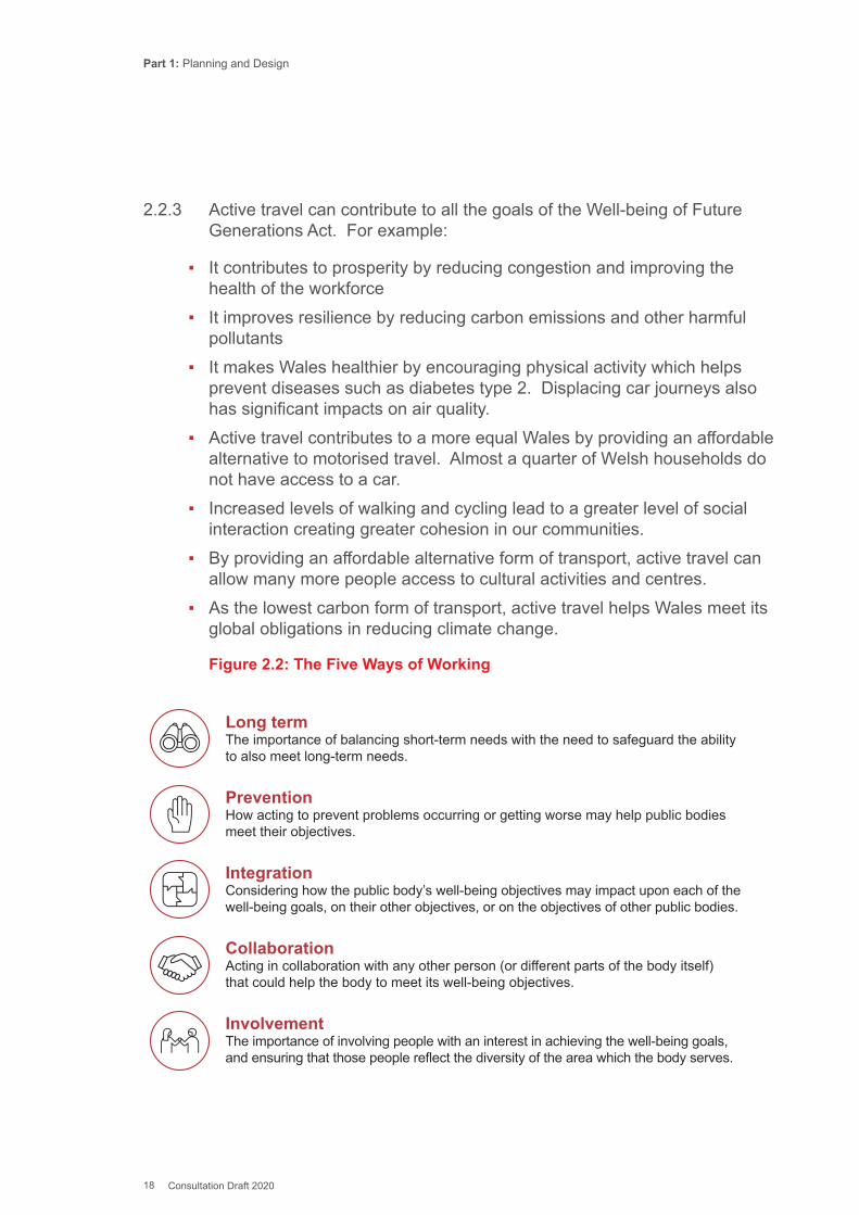
2.2.3 Active travel can contribute to all the goals of the Well-being of Future Generations Act. For example:
▪ It contributes to prosperity by reducing congestion and improving the health of the workforce
▪ It improves resilience by reducing carbon emissions and other harmful pollutants
▪ It makes Wales healthier by encouraging physical activity which helps prevent diseases such as diabetes type 2. Displacing car journeys also has significant impacts on air quality.
▪ Active travel contributes to a more equal Wales by providing an affordable alternative to motorised travel. Almost a quarter of Welsh households do not have access to a car.
▪ Increased levels of walking and cycling lead to a greater level of social interaction creating greater cohesion in our communities.
▪ By providing an affordable alternative form of transport, active travel can allow many more people access to cultural activities and centres.
▪ As the lowest carbon form of transport, active travel helps Wales meet its global obligations in reducing climate change.
Figure 2.2: The Five Ways of Working
Long termThe importance of balancing short-term needs with the need to safeguard the ability to also meet long-term needs.
PreventionHow acting to prevent problems occurring or getting worse may help public bodies meet their objectives.
IntegrationConsidering how the public body’s well-being objectives may impact upon each of the well-being goals, on their other objectives, or on the objectives of other public bodies.
CollaborationActing in collaboration with any other person (or different parts of the body itself) that could help the body to meet its well-being objectives.
InvolvementThe importance of involving people with an interest in achieving the well-being goals, and ensuring that those people reflect the diversity of the area which the body serves.

Part 1: Planning and Design
19 Consultation Draft 2020
2.2.4 The Active Travel Act reflects many of the ways of working: it is long term in requiring local authorities to develop plans looking fifteen years into the future. Active travel is also preventative in nature, for example, in helping to avoid many health problems and reducing climate harming emissions. It is integrated, with each active travel intervention helping to achieve several of the national goals. The effective delivery of the aims of the Act requires different departments of Welsh Government and local authorities to collaborate. It involves people: engagement and consultation in the planning of the networks is a key requirement of the Act.
2.2.5 The Office of the Future Generations Commissioner has produced a Future Generations Framework for projects – a ‘framework for thinking’ to help bodies fully implement the Well-being of Future Generations (Wales) Act. It is to be used when developing and designing infrastructure projects as it will help organisations work through the five ways of working and consider how they can contribute to the well-being goals.
2.3. Environment (Wales) Act 20162.3.1 Section 6 under Part 1 of the Environment (Wales) Act 2016 introduced
an enhanced duty (the S6 duty) for public authorities in the exercise of functions in relation to Wales.
2.3.2 The S6 duty requires that public authorities must seek to maintain and enhance biodiversity so far as consistent with the proper exercise of their functions and in so doing promote the resilience of ecosystems.
2.3.3 For the development of active travel schemes, this means that local authorities should embed the consideration of biodiversity and ecosystems into their early option development, through scheme design, to day to day management activities.
2.3.4 Local Authorities must have regard to the guidance produced by the Welsh Government to assist and support public authorities to follow the S6 duty .
2.4. Programme for Government2.4.1 Successive programmes for government have contained commitments
to increasing walking and cycling. Taking Wales Forward, Welsh Government’s Programme for Government 2016-2021, contains a clear pledge to: “Ensure better access to active travel for all.”
Part 1: Planning and Design
20 Consultation Draft 2020
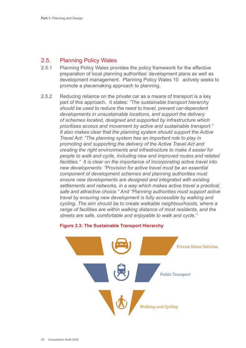
2.5. Planning Policy Wales2.5.1 Planning Policy Wales provides the policy framework for the effective
preparation of local planning authorities’ development plans as well as development management. Planning Policy Wales 10 actively seeks to promote a placemaking approach to planning.
2.5.2 Reducing reliance on the private car as a means of transport is a key part of this approach. It states: “The sustainable transport hierarchy should be used to reduce the need to travel, prevent car-dependent developments in unsustainable locations, and support the delivery of schemes located, designed and supported by infrastructure which prioritises access and movement by active and sustainable transport.” It also makes clear that the planning system should support the Active Travel Act: “The planning system has an important role to play in promoting and supporting the delivery of the Active Travel Act and creating the right environments and infrastructure to make it easier for people to walk and cycle, including new and improved routes and related facilities.” It is clear on the importance of incorporating active travel into new developments: “Provision for active travel must be an essential component of development schemes and planning authorities must ensure new developments are designed and integrated with existing settlements and networks, in a way which makes active travel a practical, safe and attractive choice.” And “Planning authorities must support active travel by ensuring new development is fully accessible by walking and cycling. The aim should be to create walkable neighbourhoods, where a range of facilities are within walking distance of most residents, and the streets are safe, comfortable and enjoyable to walk and cycle.”
Figure 2.3: The Sustainable Transport Hierarchy
Walking and Cycling
Public Transport
Private Motor Vehicles

Part 1: Planning and Design
21 Consultation Draft 2020
2.6. Equalities2.6.1 The Active Travel Act should be implemented in such a way that it
enriches the lives of as many people as possible. Developing a transport system that is not so heavily dependent on the private car and that integrates walking, cycling and public transport effectively can bring great benefits to young people, women, older people and those with disabilities, who often do not have the use of a car even if there is one in the household. However, this potential will only be realised if the needs of people with disabilities and mobility issues are properly considered at all stages of the creating of the network and they, and their representative organisations, are properly involved in engagement and consultations.
2.6.2 Section 149 of the Equality Act 2010 introduced the Public Sector Equality Duty requiring that a public authority must, in the exercise of its functions, have due regard to the need to-
a) eliminate discrimination, harassment, victimisation and any other conduct that is prohibited by or under the Equality Act;
b) advance equality of opportunity between persons who share a relevant protected characteristic and persons who do not share it; and
c) foster good relations between persons who share a relevant protected characteristic and persons who do not share it.
2.6.3 Section 153 of the Equality Act 2010 introduced powers that the Welsh Ministers may by regulations impose duties on a public authority for the purpose of enabling the better performance by the authority of the Public Sector Equality Duty. The specific duties contained in the Equality Act 2010 (Statutory Duties) (Wales) Regulations 2011 is supported by Technical Guidance published by the Equality and Human Rights Commission, which provides practical approaches to complying with the Public Sector Equality Duty. The document provides an authoritative, comprehensive and technical guide to the detail of the law including the need for equality plans, objectives and impact assessments.
2.6.4 Guidance on carrying out Equality Impact Assessments is given in Appendix J of Part 2.
2.6.5 Activities to develop the Map, and to create new or improved active travel routes and facilities, will affect some groups differently than others. To meet their duties under the Equalities Act 2010, local authorities must give consideration to these different effects and whether they can be minimised or removed. The Maps will need to show any obstacles
Part 1: Planning and Design
22 Consultation Draft 2020
along routes clearly to ensure that individuals can make an informed choice about the most appropriate route for them. Part 2 has more information about meeting the needs of different groups of users through infrastructure design, specifically Chapter 12: User Needs.
2.6.6 Local authorities, as a matter of good practice, and to fulfil their duties under the Equalities Act 2010, should ensure that in all the stages of preparing and publishing their Map as many people as reasonably possible can access both the Map and the consultations. Under the Act local authorities are also required to consult all persons who have requested to be consulted and any such persons it considers appropriate. Chapter 6 of this guidance gives more information on the consultation requirements of the Act.
2.6.7 As much local information and advice as is reasonably possible should be sought on the impact on disabled people and those with protected characteristics from the outset. This includes information on the current use of routes by people whose characteristics affect their ability to travel actively, and specific routes where access is insufficient.
2.6.8 Local authorities should seek to establish a dialogue with organisations representing people with protected characteristics, as part of developing a clear understanding of local needs, circumstances and opportunities. Local authorities should consult with their own colleagues who may have expertise or be part of networks of organisations working with people who have protected characteristics. For example, social services departments, disability information officers, the local Council for Voluntary Action, the Equalities team within the authority, the local disability information and advice line (DIAL), Public Health Wales and the third sector organisations (such as RNIB Cymru, Disability Wales, Guide Dogs Cymru, Wales Council of the Blind, Diverse Cymru, and the local Access Group). If the authority still employs an Access Officer, they will be aware of the established network arrangements in the area and should be able to suggest the best approach.
Children and Young People2.6.9 For children and young people, improved walking and cycling routes
and facilities can afford significant opportunities for access to socialising, after school clubs and activities, leisure and other services, at the same time helping to develop greater independence and a healthier lifestyle. Chapter 6 offers advice on involving young people in engagement and consultation. Increasing levels of Active Travel to school has been a Welsh Government policy objective since 1999. Since that date, active travel infrastructure to schools has been supported by specific funding,
Part 1: Planning and Design
23 Consultation Draft 2020
firstly Safe Routes to Schools and, latterly, Safe Routes in Communities. Welsh Government funds schools-based behaviour change programmes to get more pupils walking, scooting and cycling the school run.
2.6.10 The Learner Travel Measure (2008) sets out criteria for assessing whether a walking route from a pupil’s home to their school is “available”. The criteria used are specific to the Measure and are employed solely for determining the effective length of the shortest available route. They are not a factor in the assessment of active travel routes. Routes to school assessed under the Learner Travel Measure that do not meet the Design Guidance standards, should be considered for inclusion in the Active Travel Network Map as future routes with a view to their improvement.
Women2.6.11 There is a clear gender divide in active travel especially in cycling, with
only 6% of women in Wales currently cycling at least once a month compared with 12% of men. Women also make fewer walking trips, but the difference is less stark. There is evidence that women are more likely to be deterred from cycling by perceived dangers of cycling in traffic. There are also cultural and lifestyle issues that impact on women’s propensity to cycle. It is therefore important that women are well represented in decision making processes around active travel and are given particular consideration when targeting promotional activities.
2.7. WelTAG2.7.1 WelTAG is a framework for thinking about the strategic case for
proposed changes to the transport system. It contains best practice for the development, appraisal and evaluation of proposed transport interventions in Wales. WelTAG is recommended as the starting point whenever a problem is identified with the transport system or within another area that is affected by, or affects, the transport system. The WelTAG process must be applied to all transport projects funded in part or in full by the Welsh Government.
2.7.2 The ATNM process has required local authorities to take account of the views of stakeholders when identifying existing and proposed active travel routes and related facilities. This work can inform the WelTAG process, including development of the Strategic Case, during the identification and preparation of scheme proposals.

Part 1: Planning and Design
24 Consultation Draft 2020
2.8. Sustainable Drainage 2.8.1 Schedule 3 of the Flood and Water Management Act 2010 came into
force in Wales on 7 January 2019. Supported by a suite of secondary legislation it introduced a duty on developers to seek approval for SuDS to be used in the management of surface water. The duty applies where the area covered by construction work equals or exceeds 100 square metres.
2.8.2 The Statutory SuDS Standards, which accompany the legislation, set out the requirements for the design, construction, operation and maintenance of sustainable drainage systems. The role of approving, and in appropriate cases adopting, the sustainable drainage system falls to the 22 SuDS Approving Bodies (SABs) in Wales, a function of the local authority. Requirements for adoption and maintenance arrangements are set out in the Statutory Standards and the separate Statutory Guidance . The SABs must have regard to the Statutory Guidance produced by the Welsh Government to assist with the interpretation and implementation of the policy.
2.8.3 The policy seeks to manage surface water runoff in a way that both employs and mimics natural processes, with increased protection for property from the risk of flooding, within project designs. It promotes the management of surface water close to its source and close to the surface of the land, creating multi-functional spaces through better integration of drainage solutions with added amenity and biodiversity benefits.
2.8.4 SuDS are viewed as one of the key tools for facilitating sustainable development and helping public bodies meet obligations under the Well-being of Future Generations (Wales) Act 2015.
Part 1: Planning and Design
25 Consultation Draft 2020
3.1. The Duties under the Active Travel Act3.1.1 The duties arising from the Act apply to the whole authority and are not
specific to one department. Paragraph 1.1.6 includes a guide to which parts of this guidance are particularly relevant to which local government functions.
3.1.2 The duties are:
▪ for local authorities to produce maps of existing active travel routes and related facilities in a local authority’s area (Section 3) and of the new and improved active travel routes and related facilities needed to create integrated networks for active travel in a local authority’s area (Section 4) and to submit these maps to the Welsh Ministers for approval within a prescribed timetable (Sections 3(5) and 4(6)).
▪ requiring local authorities to have regard to those maps in preparing transport policies and to ensure that there are new and improved active travel routes and related facilities (Section 6).
▪ requiring the Welsh Ministers (Section 8) and local authorities (Section 5 (7)) to report on levels of active travel;
▪ requiring the Welsh Ministers and local authorities, in carrying out certain functions under the Highways Act 1980, to take reasonable steps to enhance the provision made for walkers and cyclists and to have regard to the needs of walkers and cyclists in the exercise of certain other functions (Section 9);
▪ requiring the Welsh Ministers and local authorities to exercise their functions under this Act so as to promote active travel journeys and secure new and improved active travel routes and related facilities (Section 10).
3.1.3 This guidance explains what these duties mean in practice and advises local authorities and highway authorities on how to meet these duties. Appendix A sets out the powers and duties that were created by the Act, and the bodies affected by the powers and the duties.
Chapter 3: The Duties on Local Authorities
Part 1: Planning and Design
26 Consultation Draft 2020
3.2. Timescale for the Submission of the Active Travel Network Map3.2.1 The Act requires local authorities to submit their Map to Welsh
Government no later than three years after the date on which their Map was last approved.
3.2.2 The Act gives Welsh Government the power to specify a different time period by issuing a direction to a local authority.
3.2.3 Where local circumstances have changed and there is an urgent need for an alteration to the future routes on the Active Travel Network Map, a local authority may request that Welsh Ministers direct them to review their Map by an earlier date.
3.2.4 Such a direction would specify the area to be covered in the review and the date by which the next full review of the Map must be submitted.
3.2.5 Any review covering part only of an authority must follow the provisions outlined in paragraph 5.14 of this guidance.
3.2.6 The Act gives local authorities the power to revise their Map at any point without submitting it to Welsh Ministers for approval. It is important to note that routes not identified on a Map approved by Welsh Ministers will not be eligible for Welsh Government funding.
3.3. Where the Duties Apply3.3.1 Under section 2(4) of the Act the Welsh Ministers are empowered to
designate localities in a Direction. The duty to map routes is specific to those designated localities. The Direction was made on 2 October 2014 and was sent to all local authorities in Wales. The text of the Direction can be found in Annex B, and the Direction itself can be viewed at: www.wales.gov.uk/topics/transport/walking-cycling/activetravelact/implementation/?lang=en.
3.3.2 It is important to note that duties relating to promotion of active travel and making provision for walkers and cyclists in exercise of certain functions apply to the whole of the local authority area.
3.3.3 Local authorities must ensure that they are meeting the duties specified within their designated localities. However, local authorities are encouraged to map and make improvements in other areas where there is demand. Further advice on the function of designated localities is given in paragraph 5.2.

Part 1: Planning and Design
27 Consultation Draft 2020
3.3.4 Local authorities may choose to map areas in England and work together with authorities in England to ensure an effective network. However, there is no requirement to do so as the reach of the Act ends at the border.
Part 1: Planning and Design
28 Consultation Draft 2020
4.1. Introduction4.1.1 “Active travel” means walking and cycling for the purpose of making
journeys. An “active travel journey” means any purposeful journey to a destination.
4.1.2 The definition includes travel to work, travel to school and other educational facilities, travel to the shops, travel to leisure facilities, travel to public transport interchanges and so on. The definition of Active Travel Routes excludes routes that are for purely recreational use (for example, routes intended as mountain bike trails or off-road circuits) as well as routes that do not connect facilities and services to each other or with residential areas.
4.1.3 In practice, the best active travel routes will be widely used for recreation. While the aim of the Act is to promote walking and cycling as a mode of transport, the Welsh Government also strongly supports recreational walking and cycling and cycle sport. Walking and cycling for leisure is strongly linked to a person’s willingness to travel actively. A high level of recreational walking and cycling on a route is an indicator of a high-quality route and should be considered a sign of success. However, such usage is secondary; active travel resources should only be invested in routes likely to produce modal shift.
4.1.4 Part 2 sets out what to consider in determining whether a route is suitable, based on its condition, gradient and other factors. The responsibility for determining the suitability of a route to include on the ATNM lies with the local authority. Part 2 contains advice on network planning, which should be used for determining destination points and routes between them.
4.2. Terminology4.2.1 Active travel is a useful term to differentiate between walking and cycling
as a means of transport and walking and cycling solely for leisure. However, the term is not yet widely understood amongst the general public. In dealing with the public it may therefore be preferable to use terms such as “walking and cycling as a means of transport” or “walking and cycling for everyday journeys” to introduce the topic, though the term active travel, with an explanation, should be used at some point in any communications relating to the Act. To avoid confusion, the distinction between walking and cycling for transport and as a leisure activity should be maintained.
Chapter 4: Definitions
Part 1: Planning and Design
29 Consultation Draft 2020
4.3. Definition of Active Traveller - walkers, cyclists and other highway users 4.3.1 The term “walker” embraces not only those who travel by foot (walking or
running), but also users of wheelchairs or other mobility aids. Somebody using an electric wheelchair, mobility scooter, or similar vehicle would also be considered a walker rather than a motorised travel user. This reflects that an electric wheelchair or mobility scooter can be used on a pavement and are not suitable for driving on the road. “Cycling” and “cyclist” refers to users of pedal cycles, but not motorbikes. This definition of cycling includes e-bikes (also called electric pedal-assisted cycles, electric cycles or pedelecs). These are cycles where electric motors assist the cyclist by providing extra power to the pedals, making it easier to cycle. They are distinct from electrically powered motorbikes, where the motor provides all propulsion. Untypical cycles, such as adaptive bikes, which are cycles or tricycles specially adapted for use by a person with a disability, cargo bikes and recumbents are also included within the definition of cycling.
4.3.2 The needs of people with disabilities who need to drive motor cars to access services must be taken into account when an active travel scheme requires reduced access and parking for motor vehicles.
4.3.3 Micro-scooters, roller blades, skateboards and other similar modes of travel are not included in the statutory definition of active travel. However, these modes of travel can complement walking and cycling. For example, scooters are widely used by children for travel to school. Their use should not be discouraged or impeded when they provide an attractive form of transport.
4.3.4 Walking and cycling are brought together in the Act because they share a number of characteristics. However, that does that mean they can be treated the same. The cycle is a machine that can travel at speed which makes it an ideal replacement for the motor car for many journeys, but it also means that it can be unsuitable for sharing paths with pedestrians. Part 2 contains advice on assessing whether a route could be shared by cyclists and pedestrians.
Part 1: Planning and Design
30 Consultation Draft 2020
4.3.5 Equestrianism is overwhelmingly for leisure purposes rather than as a mode of transport as it rarely displaces a car journey. Forms of equestrian travel (horse riding, carriage driving, pony and trap etc) are not considered forms of active travel. However, in delivering the provisions of the Act, local authorities should be aware that equestrians are vulnerable road users and should not restrict equestrian access to routes that they currently enjoy. Bridleways can be used by equestrians, walkers and cyclists and so may form part of an active travel route, but enhancements to bridleways should not impede equestrian use or require them to use a less safe route instead. In some cases, it may be more appropriate for all users if separate provision is made for walkers and cyclists.
Part 1: Planning and Design
31 Consultation Draft 2020
5.1. Who the network is for?5.1.2 The purpose of the Act is to dramatically increase the number of people
in Wales who walk and cycle for everyday journeys, in particular to use these modes for the high proportion of regular journeys that are less than 2.5 miles in length. This means that the Active Travel Network (ATN) must be perceived to offer the same levels of comfort, safety and security that people encounter when using other modes. Advice on the practicalities of planning the ATN is included in Chapter 13 of Part 2.
5.1.3 There is ample evidence which demonstrates that perceived danger is the key barrier preventing more people taking up walking and cycling. The perceived safety of a journey will be determined by the whole route. This means that the ultimate aim of the network must be to allow people to walk or cycle safely from their homes to all key destinations. Clearly, not all residential areas will be able to accommodate infrastructure that totally separates walkers and cyclists from motor vehicles. Instead, many residential streets will be adapted to form the Basic Network: quieter streets where the speed and volume of traffic allows active travellers to share space with motor vehicles without fear of collision. A full definition of the Basic Network is given in paragraph 14.4 of Part 2. Routes making up the Basic Network should be included on the ATNM and may be eligible for Welsh Government funding. The extent of the Basic Network and the effectiveness of its design and delivery will be a major factor in attracting new walkers and cyclists.
5.1.4 The network should cater for children to travel independently from the age at which they start secondary school.
5.1.5 The active travel network is important to the many people with disabilities who cannot otherwise travel independently. Their needs should be considered at every stage of the design and development of the network as outlined in the User Needs chapters of Part 2.
5.1.6 New active travellers are unlikely to be familiar with existing infrastructure. Clear signage and promotion materials and activities should therefore be an integral part of the development of the network.
Chapter 5: Planning the Network
Part 1: Planning and Design
32 Consultation Draft 2020
5.2. Designated Localities5.2.1 The Act does not require local authorities to map sparsely populated
areas where few people are likely to make active travel journeys. The 2014 Direction designating localities under the Active Travel Act lists the designated localities where the mapping duties apply. See also 3.3 and Appendix B in this Guidance.
5.2.2 This mechanism is not intended to be an obstacle to the creation of integrated networks of active travel routes that would connect people to destinations in adjacent areas beyond the boundary of the designated area. If the local authority’s assessment of demand for active travel journeys indicates that a route to places outside of designated localities will attract users, the routes should be included in the authority’s Active Travel Network Map and assessed for prioritisation. These routes have the same eligibility for funding as routes entirely within a designated settlement.
5.2.3 Similarly, the delineation of settlements using Built Up Area boundaries may result in communities situated relatively close to each other being separated by a narrow area of land outside the designated localities. Local authorities should include links between such communities if their assessment indicates that there is likely to be a demand.
5.2.4 There may also be settlements with populations below the applied population threshold but for which there is a strong case for creating integrated walking and cycling networks. These could be due to strong local demand and beneficial conditions or because of extreme seasonal population variations. In these cases, it is at the local authority’s discretion whether to include the settlement in the Active Travel Network Map, following the same mapping process as for designated localities.
5.3. Crossing Administrative Boundaries 5.3.1 Journeys do not stop at administrative boundaries. When the local
authority’s assessment indicates that there is demand for active travel journeys to places within a neighbouring authority then the two authorities concerned should liaise to determine how the cross-boundary route may be included on both Active Travel Network Maps.
5.4. Rurality5.4.1 The isolated nature of communities, sparsity of services and the
increased length of journeys will often mean that enabling active travel in rural areas requires a different approach to that for larger towns and cities. Longer journeys may be more achievable by a combination of
Part 1: Planning and Design
33 Consultation Draft 2020
active travel and public transport than by active travel alone. Local authorities may therefore want to prioritise walking and cycling links to public transport hubs (bus stops and rail stations).
5.4.2 Electric bikes (E-Bikes) are becoming increasingly popular and affordable, enabling cycling for longer journeys or over more challenging hilly terrain. They require no additional infrastructure to other cycles although destinations may offer the opportunity to connect the removable battery to a standard power socket for recharging. Local authorities may want to emphasise the potential of E-bikes in their promotion of active travel in rural areas.
5.4.3 Adopting a more flexible approach to mapping and prioritising routes that extend outside the designated localities may also be useful where the settlement is relatively close to a larger urban centre in which many of the services that attract local trips are located.
5.5. Mapping the network
The Active Travel Network Map
Local authorities shall prepare an Active Travel Network Map which shall incorporate the Existing Routes Map, with its associated facilities and statements, and the Integrated Network Map required by the Active Travel Act. Welsh Government’s standard data management system enables local authorities to compile the Map and will allow the two types of routes to be differentiated on the Map.
In preparing, consulting upon, publishing, submitting, reporting on and revising their Active Travel Network Map in accord with this guidance, local authorities will discharge their duties to prepare, consult upon, publish, submit, report on and revise their Existing Routes Map and Integrated Network Map.
Existing Routes5.5.1 The Act requires that Existing Routes which already meet or exceed the
criteria set out in Part 2 must be mapped. The existing routes shown on the Active Travel Network Map are intended to show the current network of routes suitable for making active travel journeys. Where a route has short sections or minor deficiencies that do not meet the design criteria,

Part 1: Planning and Design
34 Consultation Draft 2020
a statement indicating where the routes fall short of the Planning and Design Guidance standards can be prepared. Statements must contain sufficient detail on the shortfall in the route for an assessment to be made of its impact on the route’s usability. For example, where a path is below the width recommended by the Planning and Design Guidance, the statement must indicate the actual width and the length of the route affected by this width. Where a shortfall is likely to be permanent in nature, for example a route passing through a narrow bridge opening, an explanation should be given of why an alternative route is not being used. Mitigating factors may also be included in the statement, for example where an unlit path is only likely to be used during daylight hours, or where a narrow path will have only light usage. The information used in the statement will normally be derived from the audit process. Routes that have been audited and shown to contain a critical fail cannot be included on the Map even with a statement. Further advice on the validity of a statement may be sought from Welsh Government.
5.5.2 The primary purpose of showing the existing routes and associated statements on the Map is to provide a visual representation of progress in creating an active travel network and identifying and prioritising infrastructure improvement projects.
5.5.3 Other walking and cycling routes, including Public Rights of Way, that do not meet the design standard (and cannot be modified) or whose purpose is primarily for leisure, may be shown on the Map for completeness but cannot be classed as Active Travel Routes and should be differentiated in terms of how they are represented.
5.5.4 Part 2 provides audit tools which must be used for assessing whether a route is of sufficient standard for it to be considered suitable for active travel use and can therefore be included on the Active Travel Network Map. See Appendix H and I of Part 2.
Future Routes5.5.5 Routes that the Act requires to be shown on the Integrated Network Map
shall be referred to as the Future Routes. Future Routes to improve conditions for active travel can include both new-build alignments and modifications to existing highways and rights of way.
5.5.6 The Future Routes shown on the Active Travel Network Map are intended to show plans for the development of the network over the next fifteen years. The routes shown on the Map must be based on an analysis of where people are likely (could be expected) to make active travel journeys, see Chapter 13 in Part 2 for the recommended approach to
Part 1: Planning and Design
35 Consultation Draft 2020
network planning. The network of routes should be ambitious aiming to connect people to all key destinations which must include all current and planned schools.
5.5.7 The future routes identified on the Active Travel Network Map do not need to be highly detailed, at least in the initial stages, some routes will be shown simply as desire lines. To be included on the Active Travel Network Map, the siting of a desire line must have followed the processes set out in Chapter 13 of Part 2. Each scheme shown on the Map should be numbered and the Map should be supported by a corresponding Schedule of schemes with further brief details. Where the scheme is under active development, the detail of the scheme should be given as well as the approximate date for delivery and which plan this scheme is part of, e.g. “improvements to underpass, 2015, road safety plans”, “traffic-free multi-user path, 2016, part of improvements to the AXXX”. Where the scheme is for future development, as much detail as is available should be given. For example, “enhanced active travel access to FE college, part of planned site renewal in 2019” or “creation of a direct active travel route between village of Q and town of P, 2020-25”.
5.6. Prioritisation and Network Coverage5.6.1 The production of the Map identifies where interventions are required but
does not differentiate any priority nor set out a programme for delivery. Prioritisation is an essential element of the compilation of the Map, both in determining the order in which routes should be constructed and in demonstrating to the public the long-term nature of the development of the network. Priorities will be determined locally based on addressing local needs and issues and taking advantage of opportunities such as new development or highway improvement plans. See 13.8 in Part 2 for advice on prioritisation.
5.6.2 The construction of the network will take many years. Its construction will be effected by:
▪ Direct investment in new and improved routes using funding specifically allocated to active travel.
▪ The incremental integration of enhanced routes and facilities for walking and cycling in the design of highway improvements and new highway schemes as required by the Act.
▪ New and improved routes that are provided by new developments such as new housing, commercial, education and industrial sites (including any off-site highway improvement works as well as routes within the development).
Part 1: Planning and Design
36 Consultation Draft 2020
5.6.3 The effectiveness of the contribution that these elements can make to the construction of the network will depend on creating and maintaining a comprehensive Active Travel Network Map. A well-developed and regularly updated network map will enable enhancements associated with developments, highway improvements and traffic management schemes to properly integrate into future routes, significantly reducing the level of dedicated active travel funding required.
5.6.4 Welsh Government expects to see Maps which include fully comprehensive networks submitted by no later than the third cycle of Map (Integrated Network Map or Active Travel Network Map) submission. For cycling, and primary walking routes, fully comprehensive means a network mesh density no greater than 250 metres within designated localities and connecting all key destinations, which must include current and planned schools. Mesh density will include all routes that are assessed as being suitable for active travel, including primary routes, footways, cycle tracks/lanes, greenways and Basic Network routes (see 14.4 in Part 2 for a definition of a Basic Network route).
5.6.5 The future routes which will make up part of the network mesh density will be at various stages of development and may be no more than desire lines. To be included on the Active Travel Network Map, the siting of a desire line must have followed the processes set out in Chapter 13 of Part 2.
5.7. Preparing the Map5.7.1 Welsh Government has provided a data management system that local
authorities should use to prepare their Map. It is this format that should be used to submit the Map to the Welsh Ministers for approval.
5.7.2 The data management system provides a standard format for the Map to ensure consistency of approach across Wales.
5.7.3 A methodology for local authorities to develop a plan for a network of cycle and walking routes and showing it on the Active Travel Network Map is provided in Part 2, specifically Chapter 13 has sections on network planning, which will help inform this process.
5.7.4 The Active Travel Network Map will also show crossing points and the facilities that exist to support active travel, including cycle parking (stands, shelters, hubs), cycle hire stations, e-bike charging points, seating and public toilets. 13.1.1 of Part 2 lists the active travel facilities and the features that should be shown on the map. Facilities shown on the map must be publicly available.
Part 1: Planning and Design
37 Consultation Draft 2020
5.8. Planning Status5.8.1 Active Travel Network Maps should be used to inform the preparation
and review of Local Development Plans and Strategic Development Plans. Planning Policy Wales requires that Active Travel Network Maps inform site allocations, with priority given to sites that can be connected to existing and planned active travel routes. The Maps, therefore, have an important role in helping the planning system ensure new development is linked to the wider active travel network.
5.8.2 Active Travel Network Maps are not definitive maps, in the way the rights of way maps are, and the location of new routes can be indicative. For active travel routes being incorporated in new development, the exact route should be considered as part of the overall design for a scheme and be informed by a wider site and context analysis. This is in the context of walking and cycling being the priority in the design of new development, as required by the sustainable transport hierarchy in Planning Policy Wales. Once a route has been built, its exact location should be reflected in an updated version of the Active Travel Network Map.
5.9. Routes that are not owned by a local authority5.9.1 The agreement of landowners to showing active travel routes on the
Active Travel Network Map is not required where the route is an existing right of way, and of the appropriate classification for the use specified in the map (i.e. accessible to walkers if shown as a footpath). However, efforts should be made to bring the Active Travel Network Map to the landowner’s attention.
5.9.2 If the route is a permissive route, then the landowner’s agreement must be sought. In many cases a note to confirm agreement will be sufficient. This should be done during the compilation of the map, before the public consultation on the Map begins. If there are time restrictions on when a permissive route can be used this should be noted on the Map.
5.9.3 Consent is not required to show possible future routes on the Active Travel Network Maps, but reasonable effort should be made to notify and consult with landowners wherever possible. Depicting a route on a map does not negate the need to follow due process for route enhancements and creation (such as traffic regulation orders or path creation orders) and landowners who are unwilling to have these plans enacted on their land will have opportunities to object at the appropriate stages.
Part 1: Planning and Design
38 Consultation Draft 2020
5.10. Training and Support5.10.1 Welsh Government will offer a number of training opportunities to those
involved in planning and delivering Active Travel networks during each map submission cycle. This will include training in using the mapping system as well as training in using the Planning and Design Guidance.
5.11. Approving the Map5.11.1 In considering whether to approve the Map and supporting documents
the Welsh Ministers will take into account:
▪ whether the process set out in the guidance has been followed. ▪ whether appropriate consultation, in line with this guidance, has been
conducted; ▪ whether the form of the Map is in line with this guidance; ▪ whether the statement provides suitable explanation, in line, of why any
routes that are not up to the design standard are included on the Map. ▪ whether the network of routes and facilities shown on the Map is in line
with this guidance and the Planning and Design Guidance (for example, that routes that are not to the design standard are noted as such and that there has been appropriate network planning and destination planning);
▪ Welsh Government’s approval process will focus on the coherence of the network rather than individual routes
5.11.2 The Welsh Ministers are required to consider the above factors under the Act. Local authorities should submit details of the engagement and consultation that they have undertaken in producing the Map. A form for that purpose is included in Appendix D.
5.11.3 In order to ensure that a snapshot of the Map at the moment of approval can be preserved, an image of the Map being submitted is required. The Map should be taken off the data management system in the form of pdfs and emailed to: [email protected].
5.11.4 The Welsh Ministers may require local authorities to resubmit Maps if the authority has not consulted appropriately; has not had regard to this guidance as to the consultation and preparation of the Map, including what should be shown on the Map and its form; and/or if the explanation of the nature of the routes is insufficient.
Part 1: Planning and Design
39 Consultation Draft 2020
5.11.5 If the Welsh Ministers do not approve the Map, the local authority will be informed why the Welsh Ministers did not consider the Map to be acceptable. They will be asked to make appropriate amendments before resubmitting the Map for approval by a date specified by the Welsh Ministers. There is no limit to the number of times the Welsh Ministers may require the Map to be amended and resubmitted. Where local authorities have to resubmit Map(s) for approval because they were not approved in the previous instance this will not affect the timeframe for subsequent review and resubmission the Map(s).
5.11.6 Welsh Ministers may decide to approve only the future routes or only the existing routes on a local authority’s Active Travel Network Map, where they consider that only one set of routes has met the required standards. The approved set of routes may be eligible for funding. Where only one set of routes has been approved, the local authority must make appropriate amendments to the part of the Map that was not approved before resubmitting in accord with paragraph 5.11.5.
5.11.7 Once the Welsh Ministers have approved the Map, the statements and explanations, they should then be published.
5.12. Publishing the Map5.12.1 The completed Map is to be publicly available as soon as reasonably
practical after the Welsh Ministers have agreed the draft sent to them for approval.
5.12.2 The Act requires that local authorities publish the Map, any statement and explanation of routes that do not meet the design standard, and a report on how the level of use of active travel routes and related facilities in the local authority’s area has changed.
5.12.3 Local authorities must:
▪ publish these documents in a manner they consider appropriate; ▪ send a free copy to such persons they consider appropriate; ▪ supply a copy, free of change or at the cost of providing the copy, to any
person who requests a copy; ▪ make a copy available at all reasonable hours at places they consider
appropriate; ▪ bring to the attention of the public where copies are available.
Part 1: Planning and Design
40 Consultation Draft 2020
5.12.4 To meet the requirements for publication local authorities should:
▪ make electronic copies of the Map available on their website and ensure these are as accessible as possible;
▪ produce versions in any other languages considered appropriate as well as the versions in Welsh and English;
▪ make large print and Braille tactile maps available on request.
5.12.5 For some local authorities publishing the Map online and distributing it electronically is the approach that offers best value for money. This may allow local authorities to more easily keep the information up to date and to provide features such as layered maps for different kinds of users. However, even in areas with high rates of internet use, there are still many people who cannot or choose not to use the internet. A supply of hard copies will therefore always be required. When producing hard copies of the Map local authorities should consider how often the Map will be updated to reflect new or improved infrastructure.
5.12.6 Local authorities are encouraged to bring the Map to the attention of the local population in an appropriate way for their area.
5.12.7 The Map may also be used to inform other projects such as personalised travel planning and the development of apps and websites. The Map and underpinning data, where possible, should be made freely available to bodies undertaking this work to enable them to improve their provision of information.
5.12.8 Local authorities are also required to publish any statement and explanation of where existing routes do not meet the standard in the Planning and Design Guidance.
5.12.9 Local authorities are encouraged to publish maps of local walking and cycling routes in their communities to help encourage more people to use these modes, both online and as hard copies. An example is given in Appendix C. Those maps should make use of the data management system used to compile the Active Travel Network Map to incorporate information from the statements associated with existing routes, particularly where they indicate access restrictions, for example steps that would prevent wheelchair access or the absence of a dropped kerb.
5.12.10 Local authorities could also consider specific formats to promote tourism, to aid a large employer’s work-based travel planning, or to promote a new piece of infrastructure. Local authorities might want to use the information in the Active Travel Network Map to create maps for walkers only, or cyclists only, or specific categories of the two.
Part 1: Planning and Design
41 Consultation Draft 2020
5.12.11 Local authorities may wish to explore advertising opportunities, such as sponsorship, when publishing their maps. This may help further promote active travel and could help defray some of the publication costs.
5.13. Reviewing the Map5.13.1 The purpose of the three-year review is to enable continuous refinement
and improvement of the network. A new Active travel Network Map will be resubmitted to Welsh Ministers within three years of the date on which it was last approved.
5.13.2 The review process will be a combination of adding new future routes and changing the designation of future routes to existing routes as the infrastructure is built. Future routes that become existing routes may be statemented where parts of the route do not meet the standards of Part 2, for example where an otherwise perfect riverside route has a pinch point as it passes under a bridge. The review will also involve the removal of statements as improvements to existing routes are completed.
5.14. Partial Review of the Map5.14.1 There may be circumstances in which local authorities wish to make a
partial revision of their map earlier than required by Welsh Ministers. For example, where an unanticipated development is taking place and the authority wishes to ensure that it can be connected to the active travel network. In these circumstances the local authority may request that Welsh Ministers direct them to review their map by an earlier date, specifying the area of the authority which they wish to review, see 3.5 in this Guidance. Welsh Ministers will consider approving a partial revision subject to evidence of appropriate engagement and consultation having taken place.
5.14.2 Local authorities should ensure that all the organisations involved in the last full consultation process and all the individuals who have requested that they be consulted about the Map are informed of the intention to conduct a partial review, and that they are given an opportunity to comment. Local authorities should also ensure that any ongoing engagement mechanisms they have in place are made aware of the intention to conduct a partial review.
5.14.3 At least one public consultation event should be held in each of the settlements affected by the revision. Those events should be fully accessible, as advised in Chapter 6.
5.14.4 The consultation process should run for a minimum of 12 weeks.
5.14.5 Submitting a partial or interim review will not affect the three-year timetable for submitting the authority’s full review of the map.
Part 1: Planning and Design
42 Consultation Draft 2020
5.15. Continuous improvement5.15.1 Local authorities have a duty to make year on year improvements in their
active travel routes and facilities. Under this duty, local authorities are required to build new active travel infrastructure, as well as improve the existing infrastructure. Part 2 contains advice on how this duty should be fulfilled.
5.15.2 There are two ways that local authorities will demonstrate to Welsh Government that they have delivered this duty:
▪ Through the revision of the Active Travel Network Map. At the three-year review point, there should be a measurable difference between the existing routes on previous map and those completed on the new one.
▪ Through their annual reports in which they set out the actions taken and the costs they have incurred in developing their active travel networks. Chapter 8 of this guidance gives more information on reporting and monitoring requirements.
5.16. Funding the Network5.16.1 Welsh Government funding for active travel will only be granted for
improvement of existing routes and construction of future routes that appear on the authority’s approved Active Travel Network Map. In allocating funding, Welsh Ministers will take into account how local authorities have prioritised the improvement and expansion of their network to maximise an increase in active travel.
5.16.2 Local authorities are encouraged to seek additional sources of funding to increase and accelerate the programme of capital and revenue investment, for example by developing partnerships with the private sector to support active travel in their area. This could be in form of corporate sponsorship of schemes and infrastructure and through working with local employers to promote walking and cycling amongst their staff.
5.16.3 In addition to local authorities, numerous organisations contribute to the costs of providing walking and cycling infrastructure or promoting and marketing that infrastructure to encourage its use. Some of these are listed below:
▪ Welsh Government; ▪ European Commission; ▪ Natural Resources Wales; ▪ National Lottery.
Part 1: Planning and Design
43 Consultation Draft 2020
5.16.4 New developments should also be a contributor to the building of the network. Planning authorities may use planning obligations (Section 106 agreements) to secure improvements in roads, walking, cycling and public transport, whether as a result of a proposal on its own or cumulatively with other proposals and where such improvements would be likely to influence travel patterns. In this respect planning obligations could be used to create or improve an active travel route designated in the locality of the site.
5.16.5 The links between a development and the need for any infrastructure should be demonstrated and contributions should be fair and reasonable in scale relative to the infrastructure required. Such schemes may be related improvements to pedestrian or cycle routes which go near to a site or make it easier to access the site.
5.16.6 The Community Infrastructure Levy (CIL) can also be used to mitigate the impacts of development. An example could include improvements to travel routes. It is for local planning authorities to determine their priorities from Section 106 agreements and CIL, but monies collected from a CIL charge may be pooled to fund pedestrian and/or cycle infrastructure projects. Any CIL charge will need to be supported by robust evidence and will be tested through a public examination.
5.16.7 Local authorities should also consider alternative ways of carrying out the work such as through the use of volunteers and alternative means of contracting.
Part 1: Planning and Design
44 Consultation Draft 2020
Chapter 6: Consultation with Engagement
6.1. Preparation of the Map6.1.1 Engagement and Consultation is an essential part of the process for
preparing and reviewing the Active Travel Network Map. Networks that have been developed with the active involvement of local communities and current and potential active travellers are much more likely to be used and will be more easily implemented than those imposed from outside. Engagement events and materials also provide an opportunity to directly promote active travel.
6.1.2 Engagement should take place at the earliest stage and should be an important part of the network planning process, particularly when identifying potential routes.
6.1.3 Prior to the submission of the Map to Welsh Government, there should be a formal public consultation which should run for a minimum of 12 weeks.
6.1.4 The effectiveness of the local authority’s consultation is an important factor in Welsh Ministers’ determination of whether to approve an Active Travel Network Map. The draft Map must be accompanied by a report of the engagement and consultation process. Evidence of effective early engagement is as much of a consideration for Welsh Ministers in their assessment of the Map as the level of involvement in the formal consultation. A copy of the pro-forma for reporting on the engagement and consultation process is to be found in Appendix D.
6.1.5 Involving people in the practical considerations of the time and resources required to deliver the network will help to manage expectations. Seeking their views to help inform timescales for delivery will help the public to appreciate the long-term nature of the planning and development of the network and ensure that the proposed network addresses local issues and ambitions.
6.1.6 The Act requires local authorities to consult with all persons who have requested that they be consulted. Local authorities are given discretion over who else they consult, but, as a minimum, it is recommended that the following organisations are involved in the engagement and consultation process:
Part 1: Planning and Design
45 Consultation Draft 2020
▪ Delivery partners, including: other departments within the local authority, adjoining local authorities, Community/Town Councils, One Voice Wales, National Park authorities (where relevant), Natural Resources Wales, Canal and River Trust, Welsh Water Dwr Cymru, Severn Trent Water and Dee Valley Water, Network Rail, the Crown Estate, National Trust, Woodland Trust and the Welsh Government;
▪ The public, including: elected members, the authority’s active travel liaison group (where present), any Local Access Forum established for the area or any part of it, walking and cycling groups, transport campaign groups, local health promotion groups, local Chambers of Commerce, large employers, trade unions, educational establishments, youth centres and disability groups and children and young people.
▪ People with protected characteristics: local authorities should specifically seek to engage with groups with protected characteristics under the Equalities Act 2010. Local authorities should consider the format of both the map and the consultation to best meet this duty. For example, by producing an easy read version of the consultation. In particular, local authorities should consider how they enable people with visual impairments to engage in the consultation as, by its nature, the map will be a visual representation. Alternatives which will make what is set out in the map clear to anyone who cannot access the Map should also be planned for as part of the consultation. In practice, this will often mean an oral explanation of the plans. Some local authorities have also successfully employed tactile representations of planned developments as an alternative to two dimensional maps. It is recommended that local authorities engage with the Wales Council of the Blind (www.wcb-ccd.org.uk), who have access to an extensive network of people with visual impairments who could be invited to participate in the consultations. An information sheet on engaging visually impaired people in active travel network planning and design can be found on the Welsh Government’s website here: https://gov.wales/active-travel-network-design-engaging-visually-impaired-people.
▪ Young people: local authorities should also take proactive steps to consult children and young people and support their engagement with the implementation of the Act, reflecting the principles of the UN Convention on the Rights of the Child, in particular local authorities should consider to Article 2 (Non-Discrimination), Article 3 (Best Interests of the Child), Article 6 (Child’s Rights Healthy Survival and Development), Article 2 (Child’s Right to be Heard) and Article 31 (Right to rest, leisure and play). Local authorities should use the Children and Young People’s National Participation Standards for Wales to plan and deliver effective engagement with children and young people.

Part 1: Planning and Design
46 Consultation Draft 2020
6.1.7 Increasing active travel to school is a key objective of Welsh Government. Involving schools in identifying and planning routes that could be used by students for their daily commute is therefore a valuable form of engagement. Dedicated Programmes encouraging active travel to school will be of assistance in engaging school students in the process.
6.1.8 Every effort should be made to engage schools within the local authority in the consultation process. This could be through holding standalone events or using evidence collected through other means where pupil and residents’ involvement can be demonstrated, including:
▪ the development of school travel plans or community access plans; ▪ learner travel assessments; ▪ safe routes in communities network audits; and ▪ delivery of behaviour change programmes such as Active Journeys.
6.1.9 Local authorities should make every effort to engage groups who do not actively travel now. This could be through combining engagement on the Map with other local community events, or holding stand-alone events at schools, large employers, supermarkets, local shopping areas or other possible trip-generators.
6.1.10 Different types of consultation will be accessible for different people; whilst a vibrant on-street consultation in the centre of town may engage and excite some people this will be intimidating and exclusionary to others. It is therefore important to make use of a range of different types of consultation including face to face engagement and online consultation which may include use of social media.
6.1.11 Local authorities need to consider the appropriate level of detail to be provided when consulting with the public. Technical engineering drawings are likely to provide more detail than is necessary and prove inaccessible to the lay person. Any schemes should be clearly marked and explained, but any technical details should be made available on request rather than forming the basis of consultation materials.
6.1.12 Local authorities should liaise with other stakeholder organisations and agencies to identify opportunities to collaborate on shared engagement events to help minimise the risk of consultation fatigue.
6.1.13 Consultation on the Map does not negate any statutory requirements for consultation and engagement that may be required as part of an individual scheme. Part 2, 11.5 sets out the procedure that should be followed.
Part 1: Planning and Design
47 Consultation Draft 2020
Chapter 7: Promoting Active Travel
7.1.1 Local authorities are under a duty to exercise their functions under the Act in a manner designed to promote active travel journeys and secure new active travel routes and related facilities and improvements to existing active travel routes and related facilities. A toolkit with suggestions for how local authorities, and other bodies, could promote active travel is available on the active travel pages of the Welsh Government website.
7.1.2 Local authorities should seek to work collaboratively to promote active travel. This includes working together across local authority boundaries, but also working with other relevant agencies and organisations such as health boards, and voluntary organisations.
7.1.3 Local authorities must report to the Welsh Ministers on how they have delivered functions under the Act in a manner that promotes active travel journeys in each financial year. This report should detail activity to promote active travel undertaken by any departments in the local authority and may include activities undertaken on health promotion, or environmental protection as well as transport. The report does not need to set out the detail of all projects and can be a summary (unless the local authority wishes to provide more detail as part of meeting local active travel policy objectives). A template is included at Appendix F.
Part 1: Planning and Design
48 Consultation Draft 2020
Chapter 8: Monitoring and Reporting
8.1. Reporting Duties8.1.1 The Active Travel Act places reporting duties on both Welsh Ministers and
local authorities.
8.1.2 Welsh Ministers are required to make annual reports on the extent to which walkers and cyclists make active travel journeys.
8.1.3 The Act requires that each time the local authority submits its ATNM, the authority must present a report to Welsh Government showing how the level of use of active travel routes and related facilities in the local authority’s area has changed since the last submission of the Map.
8.1.4 The Act also requires local authorities to submit an annual report specifying the costs incurred in making year on year improvements to active travel routes and facilities in the most recent financial year. The annual report must also set out what actions local authorities have taken to promote active travel. When setting out how they have promoted active travel, local authorities are encouraged to consider the promotional activities outlined in the Promotional Toolkit, see 7.1.1. Annual reports should be submitted by 30th September each year
8.1.5 Information on how to gather the data required for the reports can be found in Chapter 20 (Monitoring and Evaluation) of Part 2.
8.1.6 Welsh Government is working with local authorities to improve the consistency of active travel monitoring data. This may result in a revised format for reporting on levels of active travel. Current templates for basic reports that will comply with the requirements of the Act are included at Appendix G.
8.1.7 Local authorities should publish the reports they submit to the Welsh Ministers on their website.
8.2. Review of the Act8.2.1 The Welsh Ministers are required to review the Act no later than five
years after the deadline for the production of the first integrated network maps (now Active Travel Network Maps). This review must assess the success (or otherwise) of securing new active travel routes and related facilities and improvements of existing active travel routes and related facilities. It will also assess progress in encouraging more people to walk and cycle more often and the lessons learnt during the delivery of the legislation.
Part 1: Planning and Design
49 Consultation Draft 2020
9.1. Duties under the Act9.1.1 The Active Travel Act places certain duties on Welsh Government and
Local Highway Authorities when fulfilling functions that have an impact on transport networks and related infrastructure.
9.1.2 The Act requires that, as highway authorities, local authorities and the Welsh Ministers must take reasonable steps to enhance the provision made for walkers and cyclists in their exercise of functions under Parts 3, 4, 5, 9, and 12 of the Highways Act 1980 as far as it is practicable to do so.
9.1.3 The Act also requires that highway authorities have regards to the needs of walkers and cyclists in exercising their functions under Parts 1, 2, 4 and 7 of the Road Traffic and Regulation Act 1984, Part 3 of the New Roads and Street Works Act 1991 and Part 2 of the Traffic Management Act 2004.
9.2. Creation and Maintenance of the Highway9.2.1 Parts 3, 4 and 5 of the Highways Act 1980 concern the creation,
maintenance, and improvement of highways respectively.
9.2.2 The duty to enhance provision for active travellers when undertaking highway construction, maintenance or improvement is a fundamental component in the construction of the active travel integrated networks. Highways authorities should seek to enhance provision unless they can demonstrate good reason not to. Thus, the consideration of the needs of active travellers should be an important consideration in all highways projects and feature in the earliest design considerations.
9.2.3 The costs of enhancing walking and cycling facilities in new road schemes will need to be taken account of as part of individual schemes and planned for accordingly.
Chapter 9: Provision for Walkers and Cyclists when Changes are Made to the Highway
Part 1: Planning and Design
50 Consultation Draft 2020
9.2.4 It may be reasonable not to include active travel provisions if they could not form part of a route that connects to an active travel destination or if the authority’s Active Travel Network Map includes a satisfactory alternative route that can be delivered more economically and within a similar timeframe.
9.2.5 However, that does not remove the need to ensure the changes in the highway enhance the safety of walkers and cyclists other than where the type of highway explicitly prohibits walkers and cyclists from its environs.
9.2.6 Highways projects in Wales must not make walking and cycling less convenient or safe.
9.2.7 Detailed guidance on how this duty should be performed is given in Chapter 17 of Part 2.
9.2.8 Local authorities should ensure they have an audit trail demonstrating how they have met this duty in each highway improvement project and where it has been determined that no active travel provisions are to be made then a justification for this decision should be provided.
9.3. Interference with Highways9.3.1 Part 9 of the Highway Act 1980 concerns interference with highways.
To meet their duty under the Act, highway authorities must enhance provision for walkers and cyclists when permitting or enforcing against interference with highways, where practicable to do so. For example, in controlling excavations of highways, local authorities should seek to enhance provision for walkers and cyclists when restoring the highway.
9.4. Acquisition of Land for Highway Purposes9.4.1 Part 12 of the Highway Act 1980 concerns the acquisition, vesting and
transfer of land for highway purposes. To meet their duty under the Act highway authorities must enhance provision for walkers and cyclists when acquiring land for highway construction where practicable to do so. For example, when acquiring land for the construction of a road, local authorities should also acquire land for the construction of active travel routes. See Chapter 17 in Part 2 for advice on how to assess the requirement to enhance facilities for active travel when undertaking highways functions.

Part 1: Planning and Design
51 Consultation Draft 2020
9.5. Traffic Regulation and Traffic Regulation in Special Cases9.5.1 Parts 1 and 2 of the Road Traffic and Regulation Act 1984 concern
general provisions for traffic regulation and traffic regulation in special cases respectively. To meet their duties under this part of the Act local authorities and the Welsh Ministers must have regard to the needs of walkers and cyclists in making traffic regulation orders prohibiting, restricting or regulating the use of a road including roads for use by walkers and cyclists. For example, if local authorities or the Welsh Ministers make a traffic regulation order to close roads for an event they must consider the effect upon walkers and cyclists when deciding to make the order and take mitigating action in making the order such as putting suitable diversions in place.
9.5.2 When planning diversions, the needs of disabled walkers and cyclists must be fully considered. Due consideration must also be given to the impact on new active travellers of any change from a segregated route to one that brings them into contact with motorised traffic.
9.6. Parking9.6.1 Part 4 of the Road Traffic and Regulation Act 1984 concerns parking
places. To meet their duties under this part of the Act local authorities must have regard to the needs of walkers and cyclists in providing off- street parking, authorising on-street parking and loading bays and the acquisition of land for parking. For example, local authorities should consider the needs of walkers and cyclists in authorising on-street parking particularly where it would have a negative effect upon on-road cycle routes. If local authorities wish to authorise on-street parking where there would be negative effects for walkers and cyclists, alternative provision to mitigate these effects must be considered.
9.7. Obstructions9.7.1 Part 7 of the Road Traffic and Regulation Act 1984 concerns bollards and
other obstructions. In placing bollards or other obstructions to prevent access to vehicles local authorities must have regard to the needs of walkers and cyclists. Local authorities must consider whether access for walkers and/or cyclists needs to be prohibited. If it does not, they must ensure that any obstructions are designed so that they do not prevent access for walkers and/or cyclists. Part 2 includes further guidance on the design of obstructions.

Part 1: Planning and Design
52 Consultation Draft 2020
9.8. Street Works9.8.1 Part 3 of the New Roads and Street Works Act 1991 concerns street
works. Local authorities must have regard to the needs of walkers and cyclists in:
▪ granting street works licences; ▪ giving directions as to the timing of street works; ▪ the placing of apparatus; ▪ restricting street works following substantial road works; ▪ exercising their duty to co-ordinate works and giving consent to place
apparatus on a protected street.
9.8.2 Local authorities must consider the effects that street works may have on walkers and cyclists when deciding whether to grant licenses and should seek to minimise any disruption for walkers and cyclists when giving any directions or placing any restrictions on street works. Chapter 19 in Part 2 gives detailed advice on how to carry out this duty.
9.8.3 If street works necessitate alterations in a route, the needs of disabled walkers and cyclists must be fully considered when putting in place the alternative arrangements for walkers and cyclists. Wherever possible, maintaining access for walkers and cyclists should be a priority during street works.
9.8.4 It is important to give due consideration to the impact on new active travellers of any change from a segregated route to one that brings them into contact with motorised traffic.
9.9. Traffic Management9.9.1 Part 2 of the Traffic Management Act 2004 concerns network
management by local traffic authorities. Under the Traffic Management Act 2004 local authorities are under a duty to manage their road network with a view to achieving, so far as may be reasonably practicable having regard to their other obligations, policies and objectives, the following objectives–
a) securing the expeditious movement of traffic on the authority’s road network; and
b) facilitating the expeditious movement of traffic on road networks for which another authority is the traffic authority.

Part 1: Planning and Design
53 Consultation Draft 2020
9.9.2 This duty requires local authorities to secure the expeditious movement of all road users, including walkers and cyclists. Local authorities must also ensure that measures to secure the expeditious movement of traffic are safe for all road users.
9.9.3 To meet their duty under the Act, local authorities must have regard to the needs of walkers and cyclists in setting priorities and making decisions about how to secure the expeditious movement of all traffic, motorised and otherwise.

54 Consultation Draft 2020
Part 2: Planning and Design
Part 2: Planning and Design
55 Consultation Draft 2020
This Chapter explains: ▪ Why the Welsh Government is promoting active travel; ▪ The purpose of this document in relation to the Act; ▪ Its status and application; and ▪ How it will be kept up to date.
10.1. Active Travel in Wales10.1.1 Active travel is a term used to describe walking and cycling when they
replace car travel for purposeful journeys. Whilst walking and cycling are in themselves healthy activities that are to be encouraged, it is when they displace car journeys that they deliver significant benefits for the health and well-being of Wales. It was to reap these benefits that the National Assembly for Wales passed the Active Travel Act into legislation in 2013. The Act had the aim of making “walking and cycling the most natural and normal way of getting about” .
10.1.2 The main barrier to more people taking up active travel is the perception of danger from motorised transport. Overcoming that perception is key to the success of the Act. Unless people can be persuaded that their journey - the entire journey - can be made safely by active travel, they will continue to use their cars. The number of active journeys people will make will depend on how comprehensive the network of routes is and how well the routes connect with each other.
10.1.3 The Act requires local authorities in Wales to produce active travel network maps that set out plans for these networks and to deliver year on year improvements in active travel routes and facilities. These routes are to be coherent, direct, safe, comfortable and attractive. As well as creating the infrastructure, the Act includes provision for making people aware of the available and planned routes through the publication of the maps and for the promotion of active travel as a means of transport. It requires highways authorities in Wales to make enhancements to routes and facilities for pedestrians and cyclists in all new road schemes and to have regard to the needs of walkers and cyclists in a range of other highway authority functions. The full text of the Act is available at: www.legislation.gov.uk/anaw/2013/7/contents/enacted.
Chapter 10: Part 2 Introduction
Part 2: Planning and Design
56 Consultation Draft 2020
10.1.4 This guidance sets out recommended approaches for planning and designing routes and networks for walking and cycling. Part 1 sets out the policy background and formal processes for complying with the Active Travel Act.
10.2. Highway Design and the Active Travel Act10.2.1 The Welsh Government wants to make walking and cycling the preferred
ways of getting around for shorter distances for people in Wales, so that:
▪ more people can experience the health benefits of active travel; ▪ we reduce our greenhouse gas emissions and air pollution; ▪ we help address poverty and disadvantage, and; ▪ we help our economy to grow by unlocking sustainable economic growth.
10.2.2 The Active Travel (Wales) Act 2013 (hereafter referred to as the Active Travel Act) gained Royal Assent on 4th November 2013. This created new duties to help to enable more active travel for local authorities and the Welsh Government. It also gave the Welsh Ministers the power to issue guidance on the location, nature and condition of active travel routes and facilities to ensure they are suitable for use.
10.2.3 The accompanying Delivery Guidance sets out the policy background, duties and processes that apply to local authorities and Welsh Government when implementing the Act. The duties relate primarily to the preparation of Active Travel Network Maps that show the extent of the existing and planned routes for Active Travel within built-up areas to be developed over a fifteen-year period.
10.2.4 Under the Active Travel Act, the Welsh Ministers and each local authority must take reasonable steps to enhance the provision made for walkers and cyclists when they are exercising their functions under Parts III, IV, V, 1X and X11 of the Highways Act 1980 (creation, maintenance and improvement of highways, interference with highways and acquisition etc. of land), as far as it is practicable to do so.
10.2.5 The Highways Act 1980 includes provisions on the creation, maintenance and improvement of highways. Active travel routes will mostly be highways in law (a highway being essentially a route over which the public has the right to pass and re-pass). This definition does exclude permissive routes, where the landowner’s consent to the use of the route would be required, but as noted above these may also be active travel routes.
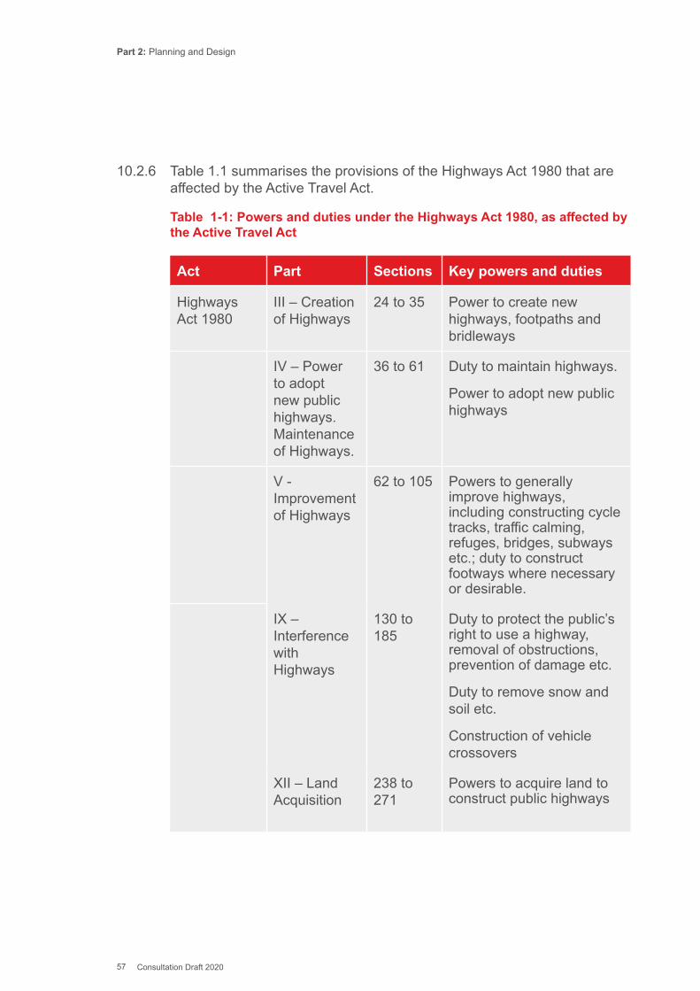
Part 2: Planning and Design
57 Consultation Draft 2020
10.2.6 Table 1.1 summarises the provisions of the Highways Act 1980 that are affected by the Active Travel Act.
Table 1-1: Powers and duties under the Highways Act 1980, as affected by the Active Travel Act
Act Part Sections Key powers and duties
Highways Act 1980
III – Creation of Highways
24 to 35 Power to create new highways, footpaths and bridleways
IV – Power to adopt new public highways. Maintenance of Highways.
36 to 61 Duty to maintain highways.
Power to adopt new public highways
V - Improvement of Highways
62 to 105 Powers to generally improve highways, including constructing cycle tracks, traffic calming, refuges, bridges, subways etc.; duty to construct footways where necessary or desirable.
IX – Interference with Highways
130 to 185
Duty to protect the public’s right to use a highway, removal of obstructions, prevention of damage etc.
Duty to remove snow and soil etc.
Construction of vehicle crossovers
XII – Land Acquisition
238 to 271
Powers to acquire land to construct public highways
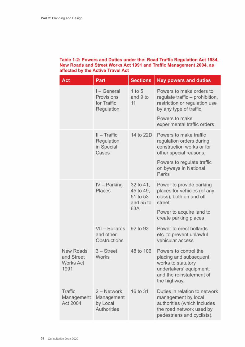
Part 2: Planning and Design
58 Consultation Draft 2020
Table 1-2: Powers and Duties under the: Road Traffic Regulation Act 1984, New Roads and Street Works Act 1991 and Traffic Management 2004, as affected by the Active Travel Act
Act Part Sections Key powers and duties
I – General Provisions for Traffic Regulation
1 to 5 and 9 to 11
Powers to make orders to regulate traffic – prohibition, restriction or regulation use by any type of traffic.
Powers to make experimental traffic orders
II – Traffic Regulation in Special Cases
14 to 22D Powers to make traffic regulation orders during construction works or for other special reasons.
Powers to regulate traffic on byways in National Parks
IV – Parking Places
32 to 41, 45 to 49, 51 to 53 and 55 to 63A
Power to provide parking places for vehicles (of any class), both on and off street.
Power to acquire land to create parking places
VII – Bollards and other Obstructions
92 to 93 Power to erect bollards etc. to prevent unlawful vehicular access
New Roads and Street Works Act 1991
3 – Street Works
48 to 106 Powers to control the placing and subsequent works to statutory undertakers’ equipment, and the reinstatement of the highway.
Traffic Management Act 2004
2 – Network Management by Local Authorities
16 to 31 Duties in relation to network management by local authorities (which includes the road network used by pedestrians and cyclists).
Part 2: Planning and Design
59 Consultation Draft 2020
10.2.7 Under the Active Travel Act, the Welsh Ministers and each local authority must also have regard to the needs of walkers and cyclists when they are exercising their functions under:
▪ Parts 1, II, IV and VII of the Road Traffic Regulation Act 1984 (general and special traffic regulation, parking places and obstructions);
▪ Part 3 of the New Roads and Street Works Act 1991 (street works); and ▪ Part 2 of the Traffic Management Act 2004 (network management by local
traffic authorities).
10.2.8 Chapter 17 provides further guidance to local authorities on the discharge of the duties set out in Tables 1.1 and 1.2 when creating, improving and managing highways, whether or not they are active travel routes.
10.2.9 Under the Active Travel Act, local authorities are required to have regard to their Active Travel Network Map when forming local transport policies under section 108(1)(a) or (2A) of the Transport Act 2000, which requires local authorities to have local transport plans.
10.2.10 This duty was also modified by the Transport Act 2006, which requires local authorities to have regard to the Wales Transport Strategy when preparing their local transport plans. These plans must be approved by the Welsh Ministers, as do the Active Travel Network Maps.
10.2.11 This document covers Planning and Design details for making improvements to walking and cycling infrastructure. The key duties with regard to this Planning and Design Guidance can be summarised as:
▪ Making year on year improvements to active travel infrastructure) ▪ Enhancing provision for walkers and cyclists when constructing,
improving or maintaining highways, ▪ Having regard to needs of walkers and cyclists when putting in place
traffic management arrangements
10.3. Status of the Guidance10.3.1 The Guidance is issued using the powers of the Welsh Ministers to give
guidance under Sections 2(6), 2(9), 3(4), 4(5) and 7(2) of the Active Travel Act.
10.3.2 The document is published by the Welsh Government for use throughout Wales and the contents must be considered when designing and maintaining active travel routes and related facilities, enhancing provision for walkers and cyclists as part of other highway schemes, or when considering the needs of walkers and cyclists as part of traffic management and road safety schemes.
Part 2: Planning and Design
60 Consultation Draft 2020
10.4. Trunk Roads10.4.1 The Welsh Government requires that the advice in this guidance must
be considered when designing active travel routes along a trunk road or where active travel routes cross or join trunk roads. Alll highway design on the trunk road network is undertaken in accordance with the Design Manual for Roads and Bridges (DMRB). The document does not intend to supersede or conflict with any mandatory clauses within the DMRB, which remains as the prime guidance document for trunk road design.
10.4.2 However, if designers consider that compliance with the advice contained within this design guidance does conflict with a mandatory clause in the DMRB, this should be addressed through the Welsh Government’s departures from standards process.
10.4.3 If the trunk road designer elects to follow alternative guidance then they should retain documentation for this design decision.
10.5. Local Roads10.5.1 For all non-trunk road networks this guidance must be considered by
local highway authorities when designing active travel routes, even where the advice in this document conflicts with current local authority design standards. Local authorities may also consider guidance contained in the Manual for streets (MFS) and MfS2, but advice contained in this document will take precedence if there is any conflict.
10.5.2 The authority should retain documentation for any design decision that does not follow the recommended dimensions and layouts in the Active Travel Design Guidance. This documentation will form the basis of the “explanation” required by section 3(6) of the Active Travel Act, which states:
When submitting an ATNM to the Welsh Ministers under this section a local authority must also submit to them –
a. a statement of the extent (if any) to which any of the active travel routes shown on it do not conform to standards specified in guidance given under section 2(6); and
b. an explanation of why the local authority has nevertheless decided that it is appropriate for them to be regarded as active travel routes.
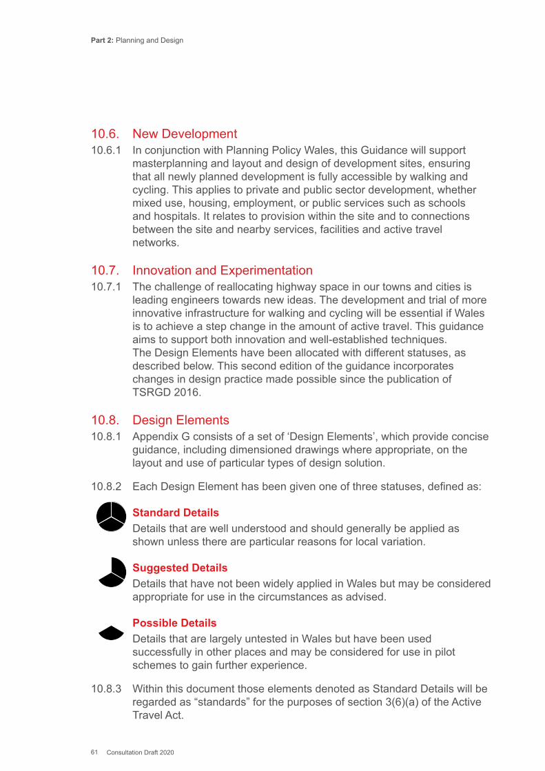
Part 2: Planning and Design
61 Consultation Draft 2020
10.6. New Development10.6.1 In conjunction with Planning Policy Wales, this Guidance will support
masterplanning and layout and design of development sites, ensuring that all newly planned development is fully accessible by walking and cycling. This applies to private and public sector development, whether mixed use, housing, employment, or public services such as schools and hospitals. It relates to provision within the site and to connections between the site and nearby services, facilities and active travel networks.
10.7. Innovation and Experimentation10.7.1 The challenge of reallocating highway space in our towns and cities is
leading engineers towards new ideas. The development and trial of more innovative infrastructure for walking and cycling will be essential if Wales is to achieve a step change in the amount of active travel. This guidance aims to support both innovation and well-established techniques. The Design Elements have been allocated with different statuses, as described below. This second edition of the guidance incorporates changes in design practice made possible since the publication of TSRGD 2016.
10.8. Design Elements10.8.1 Appendix G consists of a set of ‘Design Elements’, which provide concise
guidance, including dimensioned drawings where appropriate, on the layout and use of particular types of design solution.
10.8.2 Each Design Element has been given one of three statuses, defined as:
Standard Details Details that are well understood and should generally be applied as shown unless there are particular reasons for local variation.
Suggested Details Details that have not been widely applied in Wales but may be considered appropriate for use in the circumstances as advised.
Possible Details Details that are largely untested in Wales but have been used successfully in other places and may be considered for use in pilot schemes to gain further experience.
10.8.3 Within this document those elements denoted as Standard Details will be regarded as “standards” for the purposes of section 3(6)(a) of the Active Travel Act.
Part 2: Planning and Design
62 Consultation Draft 2020
10.8.4 The use of advice categorised as Suggested Details or Possible Details will require careful monitoring by the highway authorities who implement them to ensure that they perform as expected. Welsh Government would welcome feedback on any lessons learned to improve the guidance and to assist other highway authorities that are developing innovative schemes.
10.9. Keeping Standards Up to Date10.9.1 The field of walking and cycling design guidance is constantly evolving.
The intention is that this design guidance will be updated to take account of changes to design standards, new legislation or experience learnt from those implementing the design solutions contained within this document. This is expected to result in changes to the main guidance document and the status of some design elements, as experience is gained, together with the addition and/or deletion of others.
10.9.2 User views are essential for the successful evolution of this document and so all who use this guidance are encouraged to submit comments. These comments should be sent to the following address: [email protected]
Part 2: Planning and Design
63 Consultation Draft 2020
This Chapter provides general advice to local authorities on the principles of involving, engaging and consulting with the public and external organisations on the development of active travel networks and schemes. The requirements for consultation and providing evidence of consultation during the production and submission of the ATN map are set out in Chapter 6 and Appendix D of Part 1: Delivery.
11.1. Introduction11.1.1 The Active Travel Act requires local authorities to consult on their Active
Travel Network Maps (ATNMs). Furthermore, two of the five ways of working that make up the sustainable development principle defined by the Well-Being of Future Generations (Wales) Act 2015, relate to:
▪ Involving a diversity of the population in the decisions that affect them; ▪ Working with others in a collaborative way to find shared sustainable
solutions.
11.1.2 It is therefore important that adequate consideration is given to consultation and engagement during both the preparation of the ATNMs and the further development of active travel schemes. This guidance sets out the minimum expectations for local authorities in respect of consultation for both processes, although they are encouraged to follow best practice examples and go beyond this whenever possible.
11.1.3 Consultation should result in better design and better schemes. Good consultation at early stages can help to avoid poor decisions based on inaccurate or outdated information and gain greater community support for any new scheme. The more opportunity people have to influence and shape walking and cycling schemes for their local area, the more likely they will be to use them.
11.2. Principles of Good Practice11.2.1 The key to ensuring successful engagement on network planning and
scheme design is that it meets the ABC requirements:
▪ Accessible – with regard to location, format, style, language, timing; ▪ Broad – opportunity to get involved for everybody who is directly or
indirectly affected, including potential users;
Chapter 11: Stakeholder Participation, Engagement and Consultation

Part 2: Planning and Design
64 Consultation Draft 2020
▪ Clear parameters – clarity of scope and limitations of what is being discussed; and
▪ Suitable Tools – use of consultation and engagement tools.
11.2.2 There are numerous resources available which provide more detailed advice on successful strategies and techniques for involving, engaging, and consulting with the public, in particular: http://www.goodpracticewales.com/Resources/Citizen-Engagement http://www.involve.org.uk/
11.2.3 The following guidance focuses on aspects relevant to consulting on active travel networks and schemes.
Accessible11.2.4 Consultations on active travel networks and schemes must be accessible
to all people. Officers or consultants acting on behalf of local authorities should be experienced in engaging diverse communities.
11.2.5 Local authorities should specifically seek to engage with groups with protected characteristics under the Equalities Act 2010. Local authorities should consider the format of the consultation materials and the consultation event to best meet this duty. For example, by producing an easy read version of the consultation and having staff available to assist participants.
11.2.6 A wide range of media should be used - printed notices and online activity are not accessible for all groups and targeted engagement may well be necessary – for example using local radio, sessions with community groups such as access and disability groups, and culture groups where the main language is not English or Welsh. When engaging with children and young people, their perspective and needs must be considered (see box out).
Rights of Children and Young PersonsIn exercising their functions under the Active Travel (Wales) Act 2013, local authorities are required to undertake all reasonable measures to ensure that children and young people are involved in the planning, implementation and review of decision-making processes. In doing so, local authorities can make use of existing mechanisms including local schools councils, youth councils and advocacy services.
Part 2: Planning and Design
65 Consultation Draft 2020
All engagement with children and young people should be informed by the Children and Young People’s National Participation Standards for Wales, published by Welsh Government. This document stresses that children and young people’s participation is an ongoing process rather than simply a series of one-off engagement events.
11.2.7 Unnecessary technical details and jargon should not be used when presenting information. Engineering-style drawings and scheme illustrations should not assume any kind of engineering knowledge on behalf of those being consulted and should include clear descriptive text to aid interpretation.
11.2.8 This can be achieved through the inclusion of maps which put the scheme into context, the avoidance of unnecessary technical information, the use of Figures, sketches, and examples of similar schemes wherever possible. Where technical terms are necessary, an explanation must be included to ensure it is understood. Acronyms and abbreviations should be avoided or explained.
Broad11.2.9 Effective consultation at network and scheme level needs to target both
current and potential users of walking and cycling infrastructure. This may include people using existing routes for leisure and sports purposes, including equestrians in rural areas.
11.2.10 Possible ways of reaching large numbers of people may be through major trip generators such as employers, schools, higher and further education institutions, hospitals, and also include local businesses, community and special interest groups.
11.2.11 Early engagement within the local authority itself, in particular those authorities where network planning and scheme delivery are separated, is also essential, as is engagement with elected members and town and community councils. Further guidance on the range of local authority departments and individual officers who can contribute to the successful development of active travel strategies, networks and routes is given in Chapter 13.
Clear Parameters11.2.12 It is important to set clear parameters for any contact with the public and
other stakeholders, so that they understand clearly what can and cannot be changed as a result of their involvement, so that expectations are managed.

Part 2: Planning and Design
66 Consultation Draft 2020
11.2.13 The nature and scope of the process should be clearly defined and this should include both its mechanisms, including time scale, and the expected output of the activity, including any decision processes that follow.
11.3. Tools for Participation and Consultation11.3.1 There is a vast and constantly evolving range of consultation and
engagement tools and methods, many of which would be suitable for consulting on active travel networks and schemes. These include:
▪ Stand-alone events at key destinations and trip generators; ▪ Community Street Audits; ▪ Cycle Route Inspections; ▪ Posters and site notices along routes; ▪ Social media led events and online fora discussions, targeted at current
or potential active travellers; and ▪ Events on radio and other local media.
11.3.2 Local authorities are encouraged to seek advice from their equalities officer or their Local Equalities Forum to identify the most suitable methods and tools for use when engaging with groups representing disabled people. Where such resources are not available, it is highly recommended that additional advice is sought from local representative groups themselves.
Newtown pedestrian/cycling bridge community consultationBackground: Following requests from the local community for a bridge across the River Severn in Newtown, Powys CC undertook a feasibility study to identify a suitable site and investigate a connection between the housing and retail/employement opportunities on either side of the river. Subsequent engagement with local the community, including consultations through the INM process, regularly demonstrated strong local support for this crossing.
Stakeholder engagement: With increased funding for Active Travel being made available by Welsh Governmnent, Powys CC were able to develop an initial concept design to facilitate discussions with local stakeholders. A set of initial images were drawn up and used to work with various representative groups including
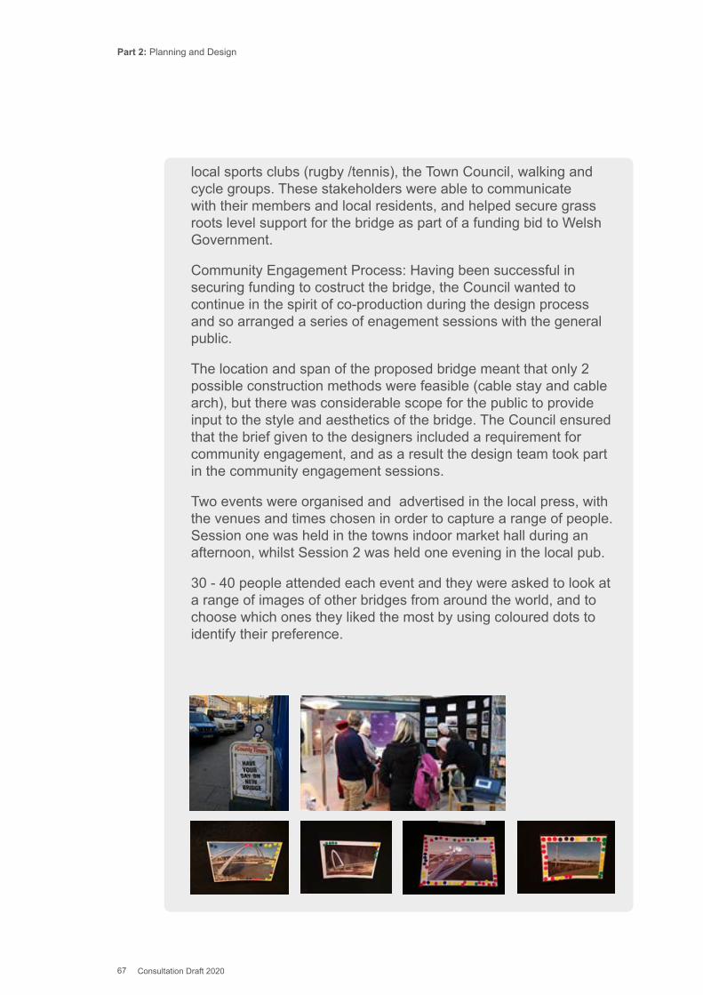
Part 2: Planning and Design
67 Consultation Draft 2020
local sports clubs (rugby /tennis), the Town Council, walking and cycle groups. These stakeholders were able to communicate with their members and local residents, and helped secure grass roots level support for the bridge as part of a funding bid to Welsh Government.
Community Engagement Process: Having been successful in securing funding to costruct the bridge, the Council wanted to continue in the spirit of co-production during the design process and so arranged a series of enagement sessions with the general public.
The location and span of the proposed bridge meant that only 2 possible construction methods were feasible (cable stay and cable arch), but there was considerable scope for the public to provide input to the style and aesthetics of the bridge. The Council ensured that the brief given to the designers included a requirement for community engagement, and as a result the design team took part in the community engagement sessions.
Two events were organised and advertised in the local press, with the venues and times chosen in order to capture a range of people. Session one was held in the towns indoor market hall during an afternoon, whilst Session 2 was held one evening in the local pub.
30 - 40 people attended each event and they were asked to look at a range of images of other bridges from around the world, and to choose which ones they liked the most by using coloured dots to identify their preference.
Part 2: Planning and Design
68 Consultation Draft 2020
11.4. Active Travel Network Map Consultation11.4.1 The preparation of the Active Travel Network Map represents a significant
opportunity for stakeholders to influence how active travel networks, routes and facilities will be developed over the long-term. As such, is it vital that sufficient opportunities are made available to gather the views of those wishing to participate.
11.4.2 Chapter 13 of this document sets out the methodologies for planning walking and cycling networks and suggests a two-stage approach to consultation in respect of the preparation of the network proposals. Further guidance on the requirements of the Act and processes for consultation on the maps can be found in Chapter 6 of Part 1: Delivery.
11.4.3 The first opportunity for engagement is at the route identification stage (Stage 2 for both the walking and cycling methodologies). This will ensure the views of stakeholders are considered at an early stage in the development of the map and will supplement the routes identified by local authorities when following the methodologies. The second opportunity for engagement is at the validation stage, where stakeholders will have the chance to view the proposed networks in their entirety and be able to make additional comments or suggestions to enhance or challenge the routes and networks identified.
11.4.4 The Act requires local authorities to consult with all persons who have requested that they be consulted. Local authorities are given discretion over who else they consult. As a minimum, it is recommended that the following organisations are involved in the engagement and consultation process:
▪ Delivery partners, including: other departments within the local authority, adjoining local authorities, Community/Town Councils, One Voice Wales, National Park authorities (where relevant), Natural Resources Wales, Canal and River Trust, Welsh Water Dwr Cymru, Severn Trent Water and Dee Valley Water, Network Rail, the Crown Estate, National Trust, Woodland Trust and the Welsh Government;
▪ The public, including: elected members, the authority’s active travel liaison group (where present), any Local Access Forum established for the area or any part of it, walking and cycling groups, transport campaign groups, local health promotion groups, local Chambers of Commerce, large employers, trade unions, educational establishments, youth centres and disability groups and children and young people.
Part 2: Planning and Design
69 Consultation Draft 2020
▪ People with protected characteristics: local authorities should specifically seek to engage with groups with protected characteristics under the Equalities Act 2010. Local authorities should consider the format of both the map and the consultation to best meet this duty. For example, by producing an easy read version of the consultation. In particular, local authorities should consider how they enable people with visual impairments to engage in the consultation as, by its nature, the map will be a visual representation. Alternatives which will make what is set out in the map clear to anyone who cannot access the Map should also be planned for as part of the consultation. In practice, this will often mean an oral explanation of the plans. Some local authorities have also successfully employed tactile representations of planned developments as an alternative to two dimensional maps. It is recommended that local authorities engage with the Wales Council of the Blind (www.wcb-ccd.org.uk), who have access to an extensive network of people with visual impairments who could be invited to participate in the consultations. An information sheet on engaging visually impaired people in active travel network planning and design can be found on the Welsh Government’s website here: https://gov.wales/active-travel-network-design-engaging-visually-impaired-people.
▪ Young people: local authorities should also take proactive steps to consult children and young people and support their engagement with the implementation of the Act, reflecting the principles of the UN Convention on the Rights of the Child, in particular local authorities should consider to Article 2 (Non-Discrimination), Article 3 (Best Interests of the Child), Article 6 (Child’s Rights Healthy Survival and Development), Article 2 (Child’s Right to be Heard) and Article 31 (Right to rest, leisure and play). Local authorities should use the Children and Young People’s National Participation Standards for Wales to plan and deliver effective engagement with children and young people.
11.4.5 Every effort should be made to engage schools within the local authority in the consultation process. This could be through holding standalone events or using evidence collected through other means where pupil and residents’ involvement can be demonstrated, including:
▪ the development of school travel plans or community access plans; ▪ learner travel assessments; ▪ safe routes in communities network audits; ▪ delivery of behaviour change programmes such as Active Journeys.
Part 2: Planning and Design
70 Consultation Draft 2020
11.4.6 Local authorities should liaise with other stakeholder organisations and agencies to identify opportunities to collaborate on shared engagement events to help minimise the risk of consultation fatigue.
11.4.7 Consultation on the maps does not negate any statutory requirements for consultation and engagement that may be required as part of an individual scheme (for example, as part of a Compulsory Purchase Order or Traffic Regulation Order). In addition to the recommendations set out below, the local authority should follow its normal engagement processes in relation to schemes.
11.5. Scheme Delivery and Consultation11.5.1 In addition to the engagement required to develop the ATNMs,
consultation and co-production are key factors in ensuring that the proposals contained therein are translated into schemes that meet the needs of the community as a whole.
11.5.2 Consultations on delivery projects should be commensurate with the scale of the scheme and populations affected by it, however the principle of co-production should be applied to the development of all schemes. For example, for bigger schemes or a programme of work, engagement is best carried out at several stages throughout the project.
11.5.3 For the majority of schemes, however, it will be appropriate to undertake engagement at two key points during the development process. The initial consultation should take place early in the project’s development. This could form part of the WelTAG assessment process if stakeholders are involved in the identification of the issues, objectives and initial concepts associated with the scheme. Where a new route is proposed to connect a primary school to a residential development, for instance, representatives of the school and the local community should be involved to help identify an appropriate solution.
11.5.4 In keeping with the Validation stage of the ATNM preparation, a second opportunity for engagement should take place following completion of the outline design of a single scheme option to provide a further opportunity for stakeholder involvement in refining the scheme design and influencing the final outcome. As a minimum, local authorities would be expected to consult with local members, town and community councils as well as local residents, stakeholders, businesses and landowners likely to be affected by the scheme.

Part 2: Planning and Design
71 Consultation Draft 2020
11.5.5 Local authorities may wish to carry out the second stage of engagement following the concept design stage where stakeholders are likely to have a greater opportunity to influence the scheme design. However, sufficient information should be available to the local authority to ensure that any co-production proposals presented at this stage are realistic in order to manage expectations.
Part 2: Planning and Design
72 Consultation Draft 2020
This chapter sets out the basic needs of people when they make journeys on foot and by cycle.
12.1. Similarities and Differences12.1.1 Walking and cycling have many similarities. They deliver significant
physical and mental health benefits, reduce congestion, create no air pollution or noise, and are low cost forms of travel. The barriers to people taking up both modes share similarities such as fast traffic speeds and poor or lack of infrastructure. Reducing speeds, through measures such as the wider adoption of 20mph limits and other techniques (see Chapter 14) benefit both Active Travel Modes.
12.1.2 The following headings, which are reflected throughout the guidance, summarise the needs of people walking and cycling. People will use routes that are:
▪ Coherent; ▪ Direct; ▪ Safe; ▪ Attractive; and ▪ Comfortable.
12.1.3 There are some important differences between walking and cycling for design purposes. Pedestrians and cyclists have distinct needs which require different approaches to planning networks and designing infrastructure. In some circumstances pedestrians and cyclists can share the same space safely and effectively, and the design of such areas is covered in Chapter 14. Pedestrians and cyclists would ideally have their own spaces so that both groups can travel without concerns over conflict.
12.1.4 Walking predominates for journeys of less than two miles whilst cycling is more convenient for longer journeys, typically up to five miles for regular utility journeys. Current levels of use of each mode are significantly different. Walking rates are relatively high, particularly for journeys of less than two miles, although there has been a long-term decline in walking rates across most of Wales. Cycle use is coming from a very low base but take up is growing, and the challenge is to increase and extend that rate of growth.
Chapter 12: User Needs
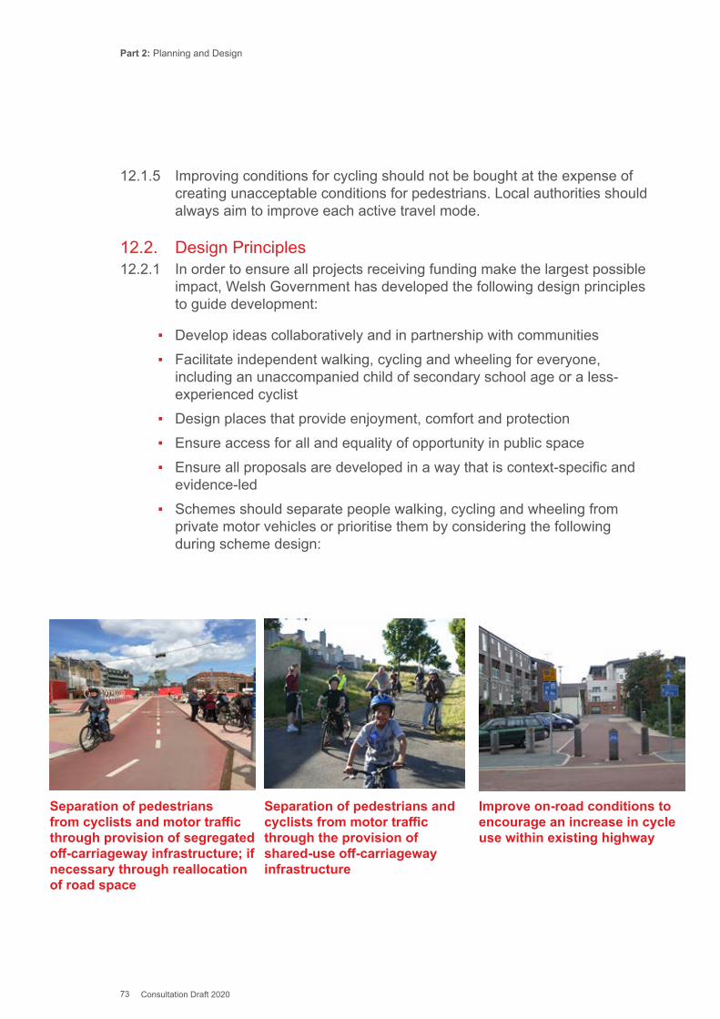
Part 2: Planning and Design
73 Consultation Draft 2020
12.1.5 Improving conditions for cycling should not be bought at the expense of creating unacceptable conditions for pedestrians. Local authorities should always aim to improve each active travel mode.
12.2. Design Principles12.2.1 In order to ensure all projects receiving funding make the largest possible
impact, Welsh Government has developed the following design principles to guide development:
▪ Develop ideas collaboratively and in partnership with communities ▪ Facilitate independent walking, cycling and wheeling for everyone,
including an unaccompanied child of secondary school age or a less-experienced cyclist
▪ Design places that provide enjoyment, comfort and protection ▪ Ensure access for all and equality of opportunity in public space ▪ Ensure all proposals are developed in a way that is context-specific and
evidence-led ▪ Schemes should separate people walking, cycling and wheeling from
private motor vehicles or prioritise them by considering the following during scheme design:
Separation of pedestrians from cyclists and motor traffic through provision of segregated off-carriageway infrastructure; if necessary through reallocation of road space
Separation of pedestrians and cyclists from motor traffic through the provision of shared-use off-carriageway infrastructure
Improve on-road conditions to encourage an increase in cycle use within existing highway

Part 2: Planning and Design
74 Consultation Draft 2020
12.3. Inclusive Design12.3.1 The network should cater for children to travel independently from the age
at which they start secondary school and to accommodate a pedestrian with a double buggy.
12.3.2 Pedestrians’ common concerns can be judged from research, undertaken for Living Streets in 2012, which asked Welsh adults which, if any, of the following problems they had encountered on their local streets.
Problem Percentage
Litter or dog fouling 76
Broken or cracked pavements 66
People parking on the pavement 62
Potholes in pavements 58
Pavements which have been badly pathed up after street works
54
People cycling on the pavement 53
Fly tipping, graffiti or abandoned cars 41
Street clutter and obstructions on the pavement 39
Badly managed street works 32
Street lithing not working/not enough or street lighting being turned off or removed.
23
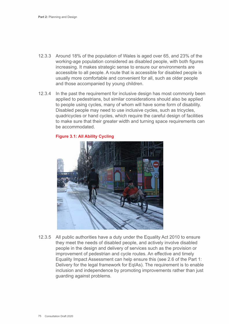
Part 2: Planning and Design
75 Consultation Draft 2020
12.3.3 Around 18% of the population of Wales is aged over 65, and 23% of the working-age population considered as disabled people, with both figures increasing. It makes strategic sense to ensure our environments are accessible to all people. A route that is accessible for disabled people is usually more comfortable and convenient for all, such as older people and those accompanied by young children.
12.3.4 In the past the requirement for inclusive design has most commonly been applied to pedestrians, but similar considerations should also be applied to people using cycles, many of whom will have some form of disability. Disabled people may need to use inclusive cycles, such as tricycles, quadricycles or hand cycles, which require the careful design of facilities to make sure that their greater width and turning space requirements can be accommodated.
Figure 3.1: All Ability Cycling
12.3.5 All public authorities have a duty under the Equality Act 2010 to ensure they meet the needs of disabled people, and actively involve disabled people in the design and delivery of services such as the provision or improvement of pedestrian and cycle routes. An effective and timely Equality Impact Assessment can help ensure this (see 2.6 of the Part 1: Delivery for the legal framework for EqIAs). The requirement is to enable inclusion and independence by promoting improvements rather than just guarding against problems.

Part 2: Planning and Design
76 Consultation Draft 2020
12.3.6 People with a disability are not a homogenous group, and it is important that the full range of diverse user needs is considered and accounted for in the design process. Advice on engaging with groups with protected characteristics is included in Chapter 11.
12.3.7 Good design features for one group of disabled people often benefit another. For instance, logical and clearly defined pedestrian routes that follow accepted guidance for signing and wayfinding will benefit a range of groups: Blind and partially sighted people will use recognised cues in the environment, such as tactile paving, buildings, kerb edges and controlled crossings for orientation and navigation; People with learning difficulties and autism benefit if routes are clear and not confusing, as would people who have mental health issues; Deaf people and those with hearing impairments benefit through improved independence if they can follow a clear logical route without needing to ask for directions. One of the causes of vision impairment is diabetes, which also causes reduced sensitivity in people’s feet so that they may have difficulty feeling the surfaces they are walking on.
12.3.8 Environments which accommodate the needs of disabled people will also be helpful to able-bodied people who are temporarily encumbered in some way – for example by carrying heavy shopping or by looking after a young child in a pushchair – or people who have concerns over personal safety.
12.4. Pedestrians’ Needs12.4.1 The design needs of pedestrians are summarised under the 5 key
principles introduced in Section 3.1. Research carried out by Living Streets (Table 3.1) reveals pedestrians’ main concerns about using the streets.
Coherence12.4.2 Pedestrian routes must allow people to easily walk to important places
including homes, shops, schools, transport interchanges, bus stops and other community facilities. Better accessibility to public transport is likely to encourage its use and decrease reliance on the private car for longer journeys. The access to and from a public transport trip can form an important part of regular physical activity.
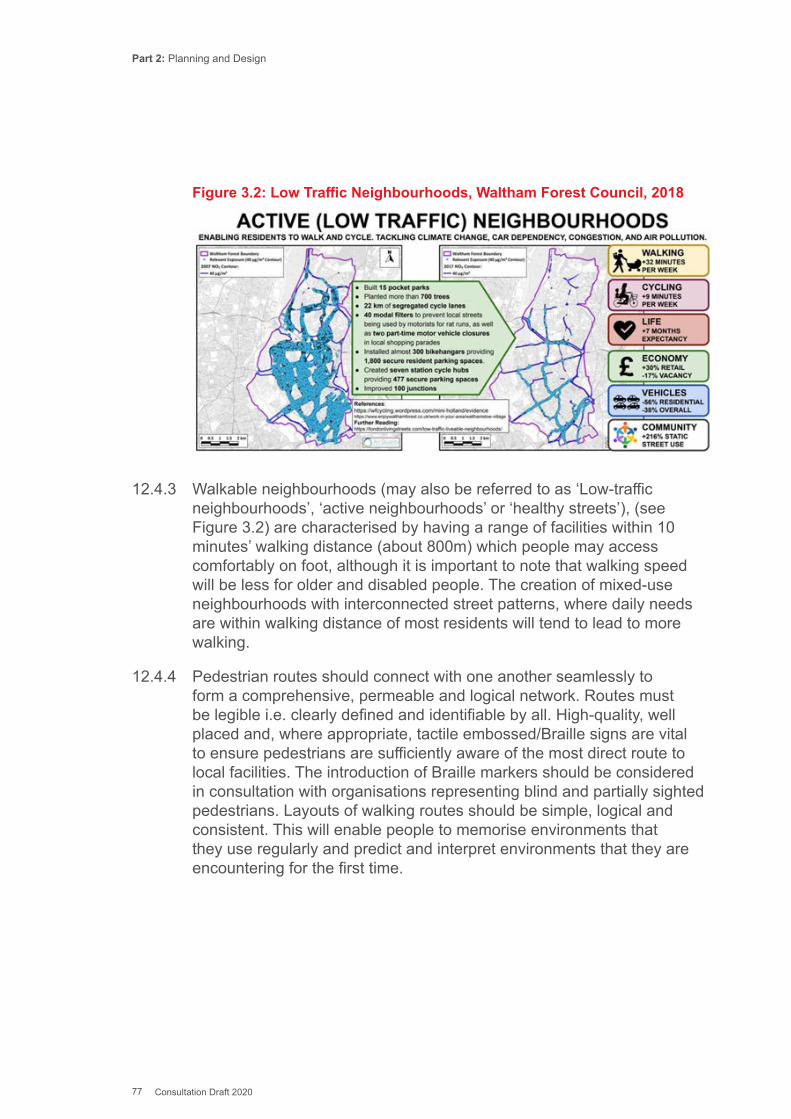
Part 2: Planning and Design
77 Consultation Draft 2020
Figure 3.2: Low Traffic Neighbourhoods, Waltham Forest Council, 2018
12.4.3 Walkable neighbourhoods (may also be referred to as ‘Low-traffic neighbourhoods’, ‘active neighbourhoods’ or ‘healthy streets’), (see Figure 3.2) are characterised by having a range of facilities within 10 minutes’ walking distance (about 800m) which people may access comfortably on foot, although it is important to note that walking speed will be less for older and disabled people. The creation of mixed-use neighbourhoods with interconnected street patterns, where daily needs are within walking distance of most residents will tend to lead to more walking.
12.4.4 Pedestrian routes should connect with one another seamlessly to form a comprehensive, permeable and logical network. Routes must be legible i.e. clearly defined and identifiable by all. High-quality, well placed and, where appropriate, tactile embossed/Braille signs are vital to ensure pedestrians are sufficiently aware of the most direct route to local facilities. The introduction of Braille markers should be considered in consultation with organisations representing blind and partially sighted pedestrians. Layouts of walking routes should be simple, logical and consistent. This will enable people to memorise environments that they use regularly and predict and interpret environments that they are encountering for the first time.
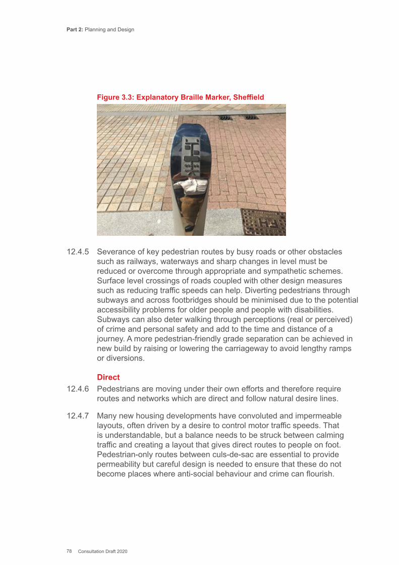
Part 2: Planning and Design
78 Consultation Draft 2020
Figure 3.3: Explanatory Braille Marker, Sheffield
12.4.5 Severance of key pedestrian routes by busy roads or other obstacles such as railways, waterways and sharp changes in level must be reduced or overcome through appropriate and sympathetic schemes. Surface level crossings of roads coupled with other design measures such as reducing traffic speeds can help. Diverting pedestrians through subways and across footbridges should be minimised due to the potential accessibility problems for older people and people with disabilities. Subways can also deter walking through perceptions (real or perceived) of crime and personal safety and add to the time and distance of a journey. A more pedestrian-friendly grade separation can be achieved in new build by raising or lowering the carriageway to avoid lengthy ramps or diversions.
Direct12.4.6 Pedestrians are moving under their own efforts and therefore require
routes and networks which are direct and follow natural desire lines.
12.4.7 Many new housing developments have convoluted and impermeable layouts, often driven by a desire to control motor traffic speeds. That is understandable, but a balance needs to be struck between calming traffic and creating a layout that gives direct routes to people on foot. Pedestrian-only routes between culs-de-sac are essential to provide permeability but careful design is needed to ensure that these do not become places where anti-social behaviour and crime can flourish.
Part 2: Planning and Design
79 Consultation Draft 2020
12.4.8 At a detailed level, as noted in Manual for Streets, pedestrian routes should be as straight as possible through road junctions. Tight corner radii will minimise the need for pedestrians to deviate from their desire lines when crossing minor roads. Crossing on a radius is hazardous for blind and partially sighted pedestrians as it is very difficult to orientate in a straight line from a radius and the person can inadvertently wander into the open road.
Safe12.4.9 Safety (both actual and perceived) is an essential user need for
pedestrians, both in the form of preventing physical harm through collisions with vehicles and minimising threats to personal safety.
12.4.10 Good road safety is achieved by separating pedestrian routes from fast vehicle routes in space and/or time; and/or by reducing vehicle speeds and flows to a level such that risks are brought to an acceptable level.
12.4.11 Fears over personal safety can be a major barrier to walking. Street lighting is an important influence on the public’s perception of what constitutes a safe street. Local authorities should ensure urban streets and paths are well lit at times they are likely to be well-used, with an even and continuous distribution of lighting, avoiding glare and pools of light and shadows. Off-road paths may need to use low-level or surface lighting to minimise the impact on wildlife. Street lighting should provide an attractive street environment which provides reassurance for pedestrians and faults should be repaired quickly.
12.4.12 Pedestrian routes should be overlooked by buildings which are inhabited and well used by pedestrians and environmental anti-social activity such as graffiti, litter or vandalism should be reduced to a minimum or removed or repaired quickly. Pedestrian routes should have clear exit and entrance points where people cannot be trapped, such as subway networks and blind corners. Overhanging shrubbery should be reduced to improve sight lines and to prevent it becoming an obstruction for blind and partially sighted people. It is also important that Highway Authorities work with other partners such as the Police to ensure pedestrians feel safe using walking routes through initiatives such as regular community policing.
Attractive12.4.13 Attractive pedestrian routes not only encourage more people to walk but
also contribute to the overall quality of an area and can help to create a sense of place through the creation of more accessible public spaces.
Part 2: Planning and Design
80 Consultation Draft 2020
12.4.14 As Manual for Streets usefully remarks ‘The propensity to walk is influenced not only by distance, but also by the quality of the walking experience. A 20-minute walk alongside a busy highway can seem endless, yet in a rich and stimulating street, such as in a town centre, it can pass without noticing. Residential areas can offer a pleasant walking experience if good quality landscaping, gardens or interesting architecture are present’ (MfS, Para 6.3.1).
12.4.15 Pedestrian routes can deliver both a place and movement function although the balance between such functions may depend on external influences such as the time of day or day of the week. A pedestrian route may deliver a movement function during the working week and revert to more of a place function during the weekend, for example by being used for a street market.
12.4.16 Manual for Streets considers the role of place in detail but in essence place function is about how people gain from an area, even when they are not moving. The availability of spaces to rest and reflect, and paths for relaxing walks, are important for mental health and wellbeing. Some quiet spaces and walks, such as areas of local parks, should therefore be included within the network of pedestrian routes where they form part of active travel routes.
12.4.17 As well as encouraging active travel, attractive streets and public realm deliver increased economic activity through increases in footfall and rateable values of high streets (Living Streets, 2013). Creating attractive pedestrian routes requires targeted reduction of street clutter, use of community led design techniques, regular street cleansing and the regular maintenance of street furniture and footway surfaces.
Comfortable12.4.18 Pedestrian comfort is influenced by a range of factors including the basic
design of the route – its width as related to the number of users and the gradient and quality of the surface – as well as other elements such as tactile paving, street furniture, drainage, cleanliness and lighting.
12.4.19 Permanent street furniture within the footway should be minimised and placed away from the main pedestrian flows. Highway Authorities should also take action to prevent the obstruction of pedestrian routes by inconsiderate placement of advertising A-boards. These unregulated advertisements can pose a risk to older people and those with visual impairments who may use the building line to navigate their walking journey.
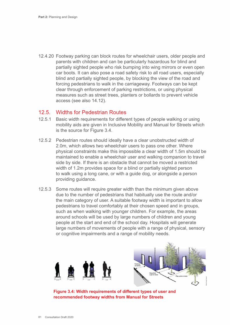
Part 2: Planning and Design
81 Consultation Draft 2020
12.4.20 Footway parking can block routes for wheelchair users, older people and parents with children and can be particularly hazardous for blind and partially sighted people who risk bumping into wing mirrors or even open car boots. It can also pose a road safety risk to all road users, especially blind and partially sighted people, by blocking the view of the road and forcing pedestrians to walk in the carriageway. Footways can be kept clear through enforcement of parking restrictions, or using physical measures such as street trees, planters or bollards to prevent vehicle access (see also 14.12).
12.5. Widths for Pedestrian Routes12.5.1 Basic width requirements for different types of people walking or using
mobility aids are given in Inclusive Mobility and Manual for Streets which is the source for Figure 3.4.
12.5.2 Pedestrian routes should ideally have a clear unobstructed width of 2.0m, which allows two wheelchair users to pass one other. Where physical constraints make this impossible a clear width of 1.5m should be maintained to enable a wheelchair user and walking companion to travel side by side. If there is an obstacle that cannot be moved a restricted width of 1.2m provides space for a blind or partially sighted person to walk using a long cane, or with a guide dog, or alongside a person providing guidance.
12.5.3 Some routes will require greater width than the minimum given above due to the number of pedestrians that habitually use the route and/or the main category of user. A suitable footway width is important to allow pedestrians to travel comfortably at their chosen speed and in groups, such as when walking with younger children. For example, the areas around schools will be used by large numbers of children and young people at the start and end of the school day. Hospitals will generate large numbers of movements of people with a range of physical, sensory or cognitive impairments and a range of mobility needs.
Figure 3.4: Width requirements of different types of user and recommended footway widths from Manual for Streets
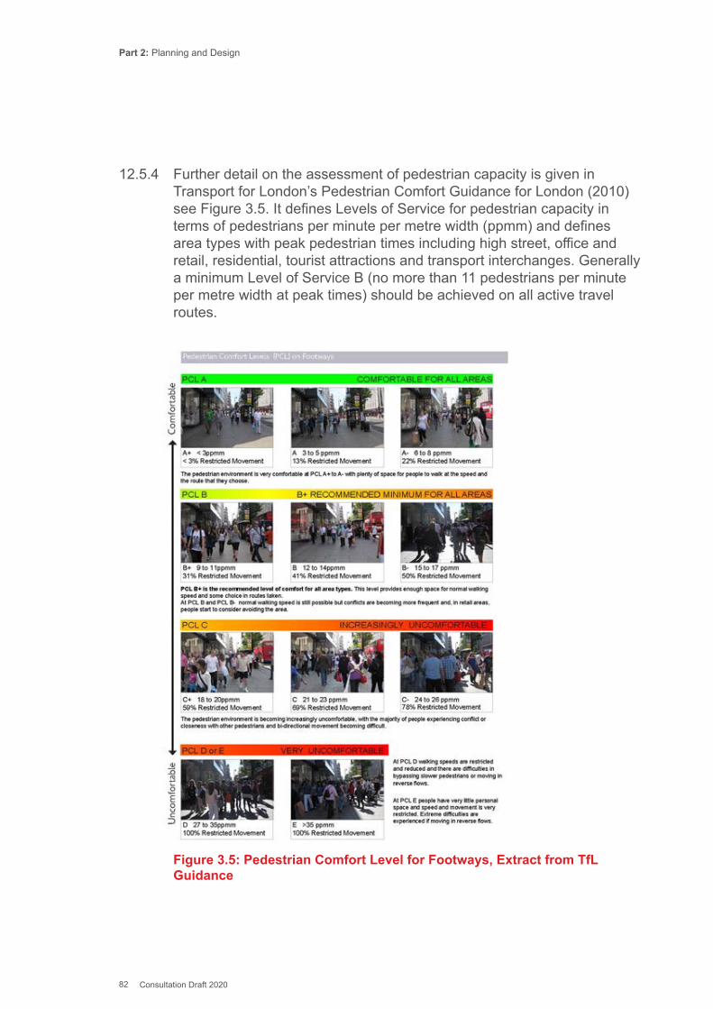
Part 2: Planning and Design
82 Consultation Draft 2020
12.5.4 Further detail on the assessment of pedestrian capacity is given in Transport for London’s Pedestrian Comfort Guidance for London (2010) see Figure 3.5. It defines Levels of Service for pedestrian capacity in terms of pedestrians per minute per metre width (ppmm) and defines area types with peak pedestrian times including high street, office and retail, residential, tourist attractions and transport interchanges. Generally a minimum Level of Service B (no more than 11 pedestrians per minute per metre width at peak times) should be achieved on all active travel routes.
Figure 3.5: Pedestrian Comfort Level for Footways, Extract from TfL Guidance
Part 2: Planning and Design
83 Consultation Draft 2020
12.6. Gradients for Pedestrian Routes12.6.1 Steep gradients have an impact on accessibility for some older people,
people with physical disabilities and parents with pushchairs.
▪ 1% (1 in 100) - is never an obstacle; ▪ 2% (1 in 50) - can be managed by most people (and also provides good
drainage); ▪ 2.5% (1 in 40) - can be managed by many people. ▪ Steeper than 2.5% - impossible for many manual wheelchair users.
12.6.2 Steeper gradients can be managed by some wheelchair users, but only over very short distances (1m or less), for example on a ramp between a bus entrance and the pavement. Even over these short distances the maximum gradient used should be no more than 10% (1 in 10).
12.6.3 A gradient of 5% (1 in 20) should generally be regarded as a desirable maximum in most situations and 8% (1 in 12) should be considered the absolute maximum. There are locations where the terrain dictates that steeper gradients cannot reasonably be avoided. At these locations, local authorities need to provide a justification for proposing steeper gradients for Active Travel Routes, as per Section 3(6) of the Active Travel Act.
12.6.4 Steep cambers and crossfalls are a problem for many people, including wheelchair users. Crossfalls should preferably be 2.5% (1 in 40) with a desirable maximum value of 3.3% (1 in 30) and an absolute maximum of 10% at crossings.
12.7. Surface Material for Pedestrian Routes12.7.1 The choice of surface materials is important to pedestrian comfort and
can also contribute to the character of a street environment. Surfaces should be even, firm and slip resistant in wet and dry conditions. The maximum deviation in height under a 1.0m straight edge should not exceed 6mm.
12.7.2 Many visually impaired people are able to distinguish contrasting colour and tone. Footway materials should be consistent, avoiding the use of random patterns which have no meaning. Good contrast between pedestrian routes, cycle tracks and carriageways can help visually impaired people to make sense of their environment.
12.7.3 Paving flags or block paving must be evenly laid; any unevenness can cause problems for some wheelchair users and some visually impaired cane users. Cobblestones or setts should not be used unless they are flat, smooth and constructed within level tolerance.
Part 2: Planning and Design
84 Consultation Draft 2020
12.7.4 Places and benches for pedestrians to rest and are helpful for older pedestrians and those with physical disabilities (see 16.2). Accessible, clean public toilets are particularly important for older people and those with children.
12.8. References for Pedestrian User NeedsTransport for London (2017) Healthy Streets for London : Prioritising walking, cycling and public transport to create a healthy city
Department for Transport (2013) Code of Practice - street works and road works, London
Department for Transport (2007) Manual for Streets, London
Department for Transport (2007) Guidance on the use of Tactile Paving Surfaces
Department for Transport (2005) Inclusive Mobility: London
British Standards Institution (2009/2010) - BS 8300:2009+A1:2010 Design of buildings and their approaches to meet the needs of disabled people. Code of practice.
Chartered Institution of Highways and Transportation (2000) Guidelines for providing for journeys on foot, London
Living Streets (2013) The pedestrian pound - the business case for better streets and places, London
National Federation of the Blind of the UK (2013) Access For Blind People In Towns. SS1401
Transport for London (2010) Pedestrian Comfort Guidance for London
12.9. Cyclists’ Needs12.9.1 In this document, ‘cyclist’ is used a shorthand for anyone who happens to
use a cycle, whatever the distance, speed or purpose of the journey, or the characteristics of the person or cycle.
12.9.2 Designs should meet the needs of everyone who cycles at any age or physical condition. Cycle routes should cater for a wide spectrum of people with different levels of confidence and experience; and cycles specially adapted to meet their physical needs (see 12.2 and Figure 3.7).

Part 2: Planning and Design
85 Consultation Draft 2020
12.10. Why do People Cycle?12.10.1 Like all road users, the choice to cycle is mainly because it is considered
the most convenient and quick mode for the journeys being made. Many users, probably more so than walking, are also motivated by the health benefits they get from cycling (Cycling Embassy of Denmark, 2012).
12.10.2 Fear of road danger from motor traffic is the most significant barrier to achieving more cycling, particularly for women and older people, who are under- represented amongst regular cyclists in the UK2.
12.10.3 Main roads usually provide the most direct, coherent routes to important destinations, but they are the places where fear of and intimidation by motor vehicles is greatest for users.
Cycling SafetyThe health benefits of cycling greatly outweigh the risks of injury encountered while cycling, however, the risks of injury while cycling are typically higher than when travelling by car. Per mile travelled, the fatality risk of cycling is comparable to walking, with around 31 pedestrians killed per billion kms walked and 27 cyclists killed per billion kms cycled (DfT, 2013d).
There are approximately 80,000 cycle casualties per year in Great Britain of which proportionately around 1,250 occur in Wales (DfT, 2013c). Of these casualties just over a third are reported to the Police, nearly all of which involved another vehicle or pedestrian.
Most of the large number of non-reported collisions are cycle-only incidents, many of which involve ice, wet or oily surfaces, gravel, debris or mud. This shows that attention must be paid to maintaining smooth, textured surfaces that are swept and receive good winter maintenance.
Collisions involving motor vehicles tend to be serious, representing over 90% of fatalities. Most of these collisions are considered by Police to be the fault of the driver, (see Figure 3.6).
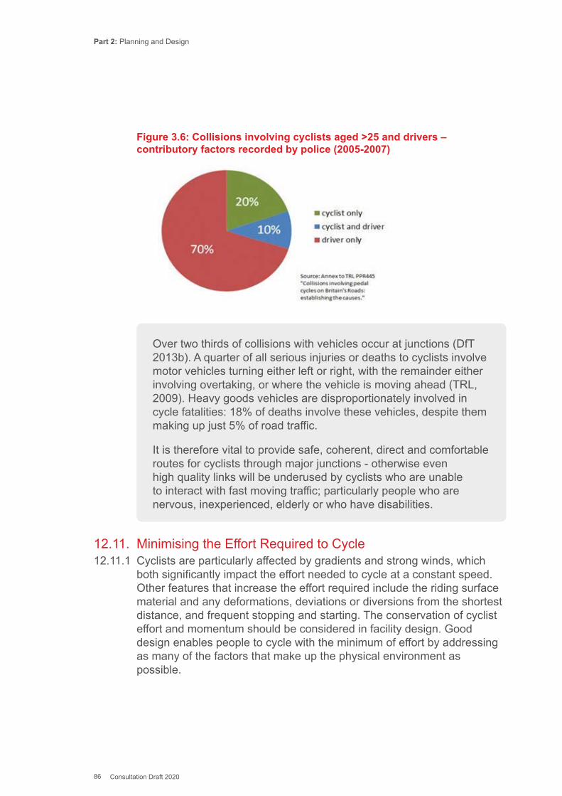
Part 2: Planning and Design
86 Consultation Draft 2020
Figure 3.6: Collisions involving cyclists aged >25 and drivers – contributory factors recorded by police (2005-2007)
Over two thirds of collisions with vehicles occur at junctions (DfT 2013b). A quarter of all serious injuries or deaths to cyclists involve motor vehicles turning either left or right, with the remainder either involving overtaking, or where the vehicle is moving ahead (TRL, 2009). Heavy goods vehicles are disproportionately involved in cycle fatalities: 18% of deaths involve these vehicles, despite them making up just 5% of road traffic.
It is therefore vital to provide safe, coherent, direct and comfortable routes for cyclists through major junctions - otherwise even high quality links will be underused by cyclists who are unable to interact with fast moving traffic; particularly people who are nervous, inexperienced, elderly or who have disabilities.
12.11. Minimising the Effort Required to Cycle12.11.1 Cyclists are particularly affected by gradients and strong winds, which
both significantly impact the effort needed to cycle at a constant speed. Other features that increase the effort required include the riding surface material and any deformations, deviations or diversions from the shortest distance, and frequent stopping and starting. The conservation of cyclist effort and momentum should be considered in facility design. Good design enables people to cycle with the minimum of effort by addressing as many of the factors that make up the physical environment as possible.
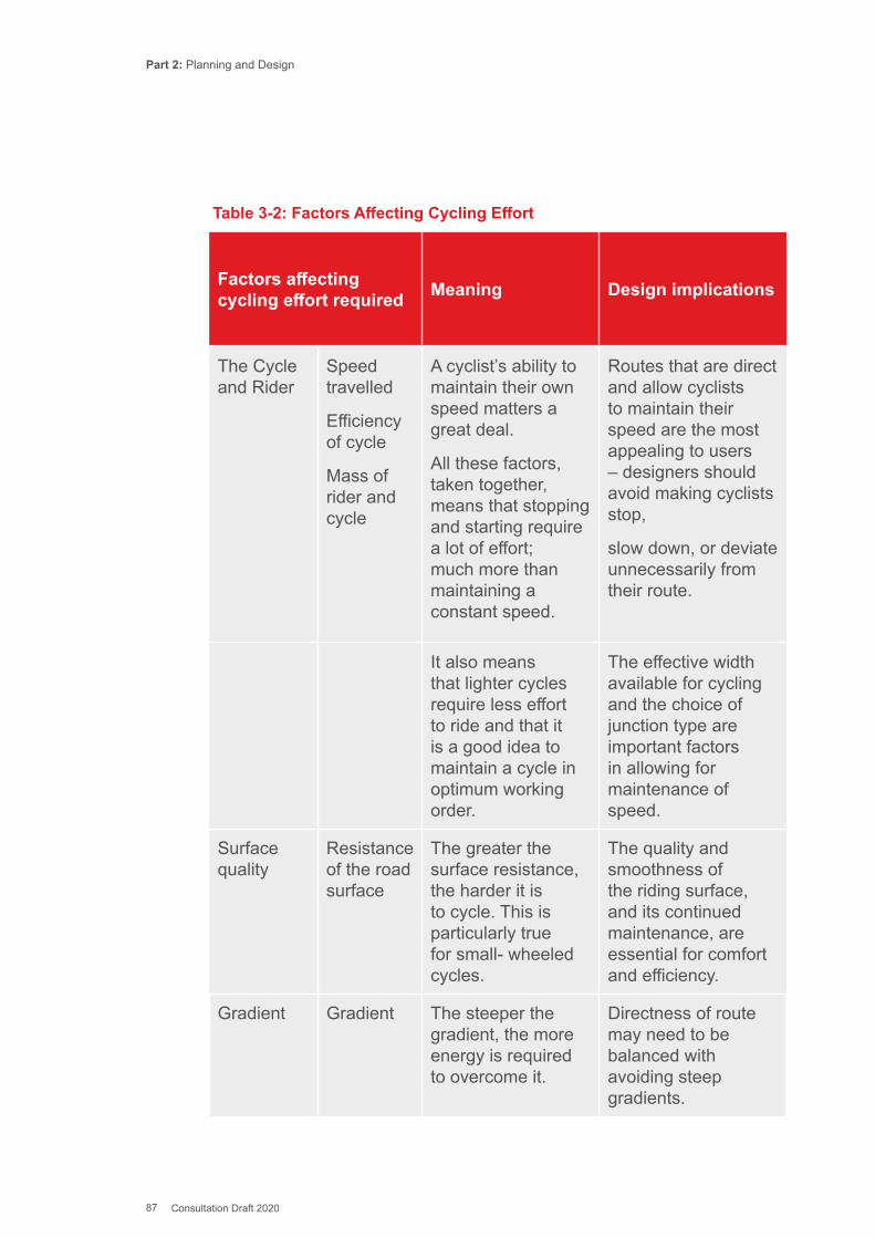
Part 2: Planning and Design
87 Consultation Draft 2020
Table 3-2: Factors Affecting Cycling Effort
Factors affecting cycling effort required Meaning Design implications
The Cycle and Rider
Speed travelled
Efficiency of cycle
Mass of rider and cycle
A cyclist’s ability to maintain their own speed matters a great deal.
All these factors, taken together, means that stopping and starting require a lot of effort; much more than maintaining a constant speed.
Routes that are direct and allow cyclists to maintain their speed are the most appealing to users – designers should avoid making cyclists stop,
slow down, or deviate unnecessarily from their route.
It also means that lighter cycles require less effort to ride and that it is a good idea to maintain a cycle in optimum working order.
The effective width available for cycling and the choice of junction type are important factors in allowing for maintenance of speed.
Surface quality
Resistance of the road surface
The greater the surface resistance, the harder it is to cycle. This is particularly true for small- wheeled cycles.
The quality and smoothness of the riding surface, and its continued maintenance, are essential for comfort and efficiency.
Gradient Gradient The steeper the gradient, the more energy is required to overcome it.
Directness of route may need to be balanced with avoiding steep gradients.
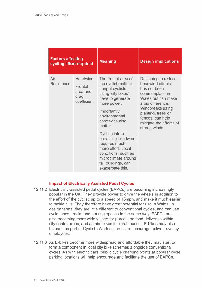
Part 2: Planning and Design
88 Consultation Draft 2020
Factors affecting cycling effort required Meaning Design implications
Air Resistance
Headwind
Frontal area and drag coefficient
The frontal area of the cyclist matters: upright cyclists using ‘city bikes’ have to generate more power.
Importantly, environmental conditions also matter.
Cycling into a prevailing headwind, requires much more effort. Local conditions, such as microclimate around tall buildings, can exacerbate this.
Designing to reduce headwind effects has not been commonplace in Wales but can make a big difference. Windbreaks using planting, trees or fences, can help mitigate the effects of strong winds
Impact of Electrically Assisted Pedal Cycles 12.11.2 Electrically-assisted pedal cycles (EAPCs) are becoming increasingly
popular in the UK. They provide power to drive the wheels in addition to the effort of the cyclist, up to a speed of 15mph, and make it much easier to tackle hills. They therefore have great potential for use in Wales. In design terms, they are little different to conventional cycles, and can use cycle lanes, tracks and parking spaces in the same way. EAPCs are also becoming more widely used for parcel and food deliveries within city centre areas, and as hire bikes for rural tourism. E-bikes may also be used as part of Cycle to Work schemes to encourage active travel by employees.
12.11.3 As E-bikes become more widespread and affordable they may start to form a component in local city bike schemes alongside conventional cycles. As with electric cars, public cycle charging points at popular cycle parking locations will help encourage and facilitate the use of EAPCs.

Part 2: Planning and Design
89 Consultation Draft 2020
12.12 Dimensions of Cycles commonly in use12.12.1 Typical conventional cycles for adults are around 1.8m in length and
0.65m in width. For an adult cyclist, 0.8m is the typical static width but extra width is needed for moving cyclists (see below). A reasonable assumption is that this amounts to a total width of 1.0m (as stated in LTN 2/08) – this is referred to as the ‘dynamic envelope’
12.12.2 People using non-standard types of cycles should not be excluded from using cycle infrastructure through lack of consideration for their needs at the design stage. There are many types of non-standard cycles (see Figure 3.7) including:
▪ Cycles with trailers for children or deliveries; ▪ Tricycles; ▪ Tandems with two or more seats; ▪ Inclusive cycles designed for disabled people e.g. quadricycles and hand
cycles; ▪ Recumbent cycles; ▪ Cargo bikes (for carrying goods or children); and ▪ Small-wheeled foldable cycles.
12.12.3 Inclusive cycles are designed for people with disabilities to use, and can be tricycles (both upright and recumbent), handcycles, tandems or solo bikes adapted to suit the rider’s disability. Although the dimensions of these cycles varies, a ‘Standard Inclusive Cycle’ has been defined which is an abstract composite of all the cycles that might reasonably use the cycle network. It includes the solo cycle, tandem, cycle + trailer, cycle + trailer bike, tricycle (upright and recumbent), hand-cycle, cargo-bike, cargo-trike, wheelchair and the mobility scooter. Designing the cycle network around this design model ensures that it is accessible to all.
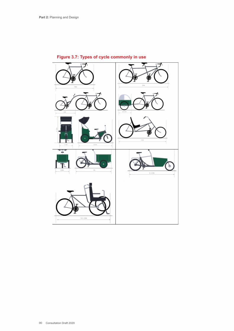
Part 2: Planning and Design
90 Consultation Draft 2020
Figure 3.7: Types of cycle commonly in use
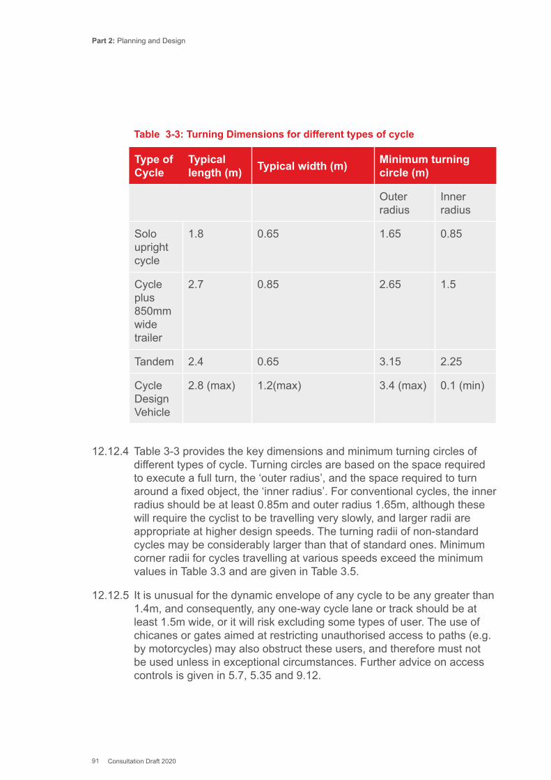
Part 2: Planning and Design
91 Consultation Draft 2020
Table 3-3: Turning Dimensions for different types of cycle
Type of Cycle
Typical length (m) Typical width (m) Minimum turning
circle (m)
Outer radius
Inner radius
Solo upright cycle
1.8 0.65 1.65 0.85
Cycle plus 850mm wide trailer
2.7 0.85 2.65 1.5
Tandem 2.4 0.65 3.15 2.25
Cycle Design Vehicle
2.8 (max) 1.2(max) 3.4 (max) 0.1 (min)
12.12.4 Table 3-3 provides the key dimensions and minimum turning circles of different types of cycle. Turning circles are based on the space required to execute a full turn, the ‘outer radius’, and the space required to turn around a fixed object, the ‘inner radius’. For conventional cycles, the inner radius should be at least 0.85m and outer radius 1.65m, although these will require the cyclist to be travelling very slowly, and larger radii are appropriate at higher design speeds. The turning radii of non-standard cycles may be considerably larger than that of standard ones. Minimum corner radii for cycles travelling at various speeds exceed the minimum values in Table 3.3 and are given in Table 3.5.
12.12.5 It is unusual for the dynamic envelope of any cycle to be any greater than 1.4m, and consequently, any one-way cycle lane or track should be at least 1.5m wide, or it will risk excluding some types of user. The use of chicanes or gates aimed at restricting unauthorised access to paths (e.g. by motorcycles) may also obstruct these users, and therefore must not be used unless in exceptional circumstances. Further advice on access controls is given in 5.7, 5.35 and 9.12.
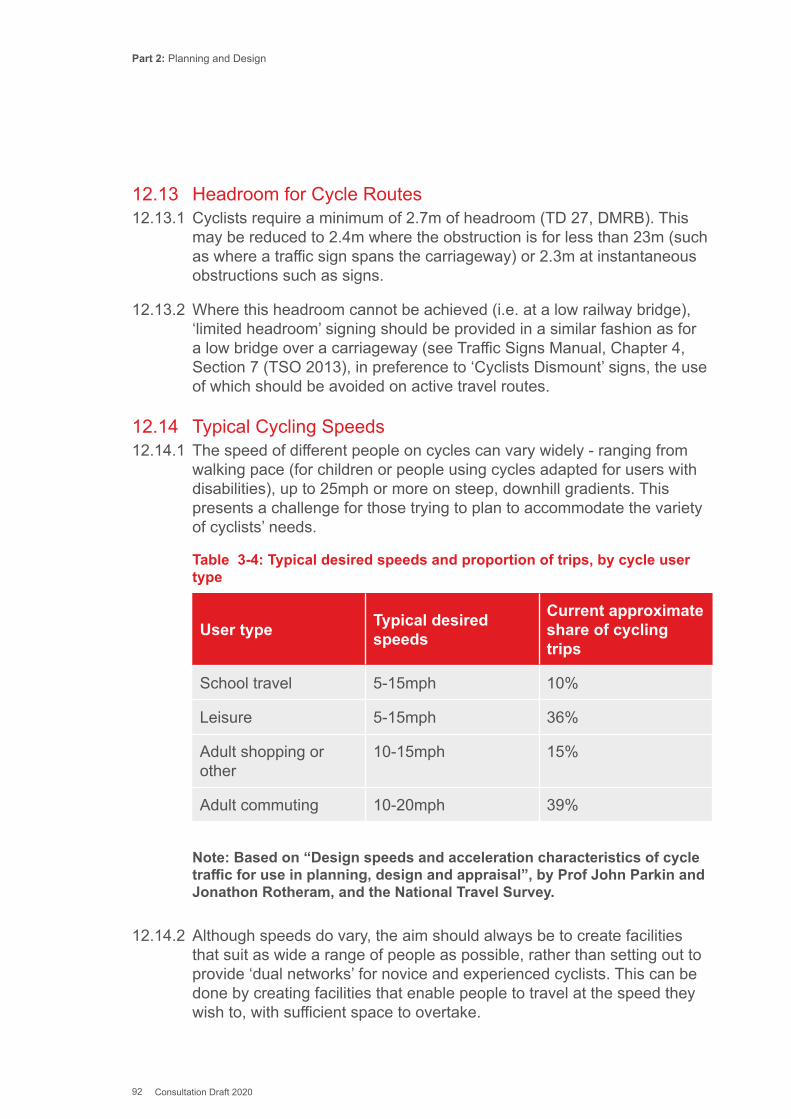
Part 2: Planning and Design
92 Consultation Draft 2020
12.13 Headroom for Cycle Routes12.13.1 Cyclists require a minimum of 2.7m of headroom (TD 27, DMRB). This
may be reduced to 2.4m where the obstruction is for less than 23m (such as where a traffic sign spans the carriageway) or 2.3m at instantaneous obstructions such as signs.
12.13.2 Where this headroom cannot be achieved (i.e. at a low railway bridge), ‘limited headroom’ signing should be provided in a similar fashion as for a low bridge over a carriageway (see Traffic Signs Manual, Chapter 4, Section 7 (TSO 2013), in preference to ‘Cyclists Dismount’ signs, the use of which should be avoided on active travel routes.
12.14 Typical Cycling Speeds12.14.1 The speed of different people on cycles can vary widely - ranging from
walking pace (for children or people using cycles adapted for users with disabilities), up to 25mph or more on steep, downhill gradients. This presents a challenge for those trying to plan to accommodate the variety of cyclists’ needs.
Table 3-4: Typical desired speeds and proportion of trips, by cycle user type
Note: Based on “Design speeds and acceleration characteristics of cycle traffic for use in planning, design and appraisal”, by Prof John Parkin and Jonathon Rotheram, and the National Travel Survey.
12.14.2 Although speeds do vary, the aim should always be to create facilities that suit as wide a range of people as possible, rather than setting out to provide ‘dual networks’ for novice and experienced cyclists. This can be done by creating facilities that enable people to travel at the speed they wish to, with sufficient space to overtake.
User type Typical desired speeds
Current approximate share of cycling trips
School travel 5-15mph 10%
Leisure 5-15mph 36%
Adult shopping or other
10-15mph 15%
Adult commuting 10-20mph 39%
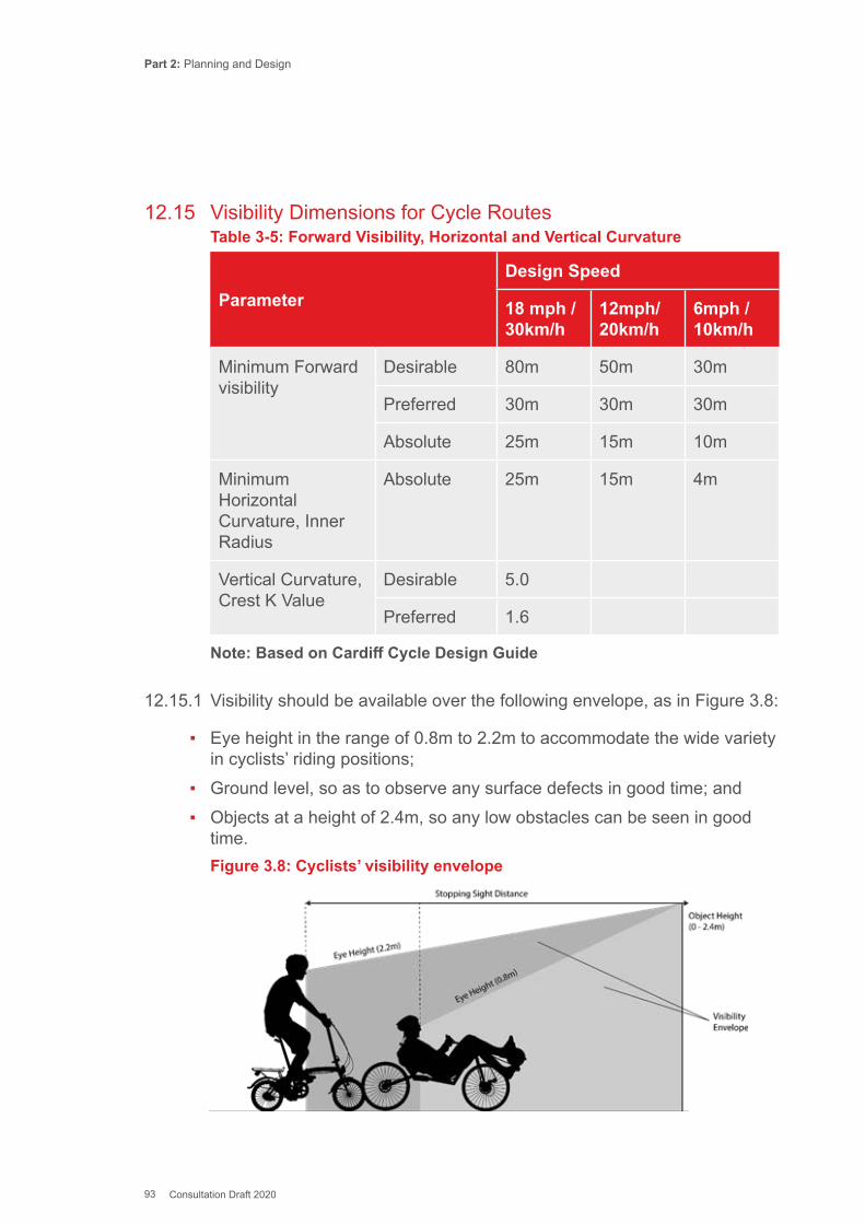
Part 2: Planning and Design
93 Consultation Draft 2020
12.15 Visibility Dimensions for Cycle RoutesTable 3-5: Forward Visibility, Horizontal and Vertical Curvature
ParameterDesign Speed
18 mph / 30km/h
12mph/ 20km/h
6mph / 10km/h
Minimum Forward visibility
Desirable 80m 50m 30m
Preferred 30m 30m 30m
Absolute 25m 15m 10m
Minimum Horizontal Curvature, Inner Radius
Absolute 25m 15m 4m
Vertical Curvature, Crest K Value
Desirable 5.0
Preferred 1.6
Note: Based on Cardiff Cycle Design Guide
12.15.1 Visibility should be available over the following envelope, as in Figure 3.8:
▪ Eye height in the range of 0.8m to 2.2m to accommodate the wide variety in cyclists’ riding positions;
▪ Ground level, so as to observe any surface defects in good time; and ▪ Objects at a height of 2.4m, so any low obstacles can be seen in good
time.Figure 3.8: Cyclists’ visibility envelope
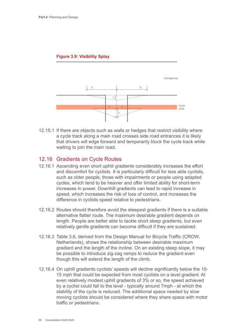
Part 2: Planning and Design
94 Consultation Draft 2020
Figure 3.9: Visibility Splay
12.15.1 If there are objects such as walls or hedges that restrict visibility where a cycle track along a main road crosses side road entrances it is likely that drivers will edge forward and temporarily block the cycle track while waiting to join the main road.
12.16 Gradients on Cycle Routes12.16.1 Ascending even short uphill gradients considerably increases the effort
and discomfort for cyclists. It is particularly difficult for less able cyclists, such as older people, those with impairments or people using adapted cycles, which tend to be heavier and offer limited ability for short-term increases in power. Downhill gradients can lead to rapid increase in speed, which increases the risk of loss of control, and increases the difference in cyclists speed relative to pedestrians.
12.16.2 Routes should therefore avoid the steepest gradients if there is a suitable alternative flatter route. The maximum desirable gradient depends on length. People are better able to tackle short steep gradients, but even relatively gentle gradients can become difficult if they are sustained.
12.16.3 Table 3.6, derived from the Design Manual for Bicycle Traffic (CROW, Netherlands), shows the relationship between desirable maximum gradient and the length of the incline. On an existing steep slope, it may be possible to introduce zig-zag ramps to reduce the gradient even though this will extend the length of the climb.
12.16.4 On uphill gradients cyclists’ speeds will decline significantly below the 10- 15 mph that could be expected from most cyclists on a level gradient. At even relatively modest uphill gradients of 3% or so, the speed achieved by a cyclist could fall to the level - typically around 7mph - at which the stability of the cycle is reduced. The additional space needed by slow moving cyclists should be considered where they share space with motor traffic or pedestrians.
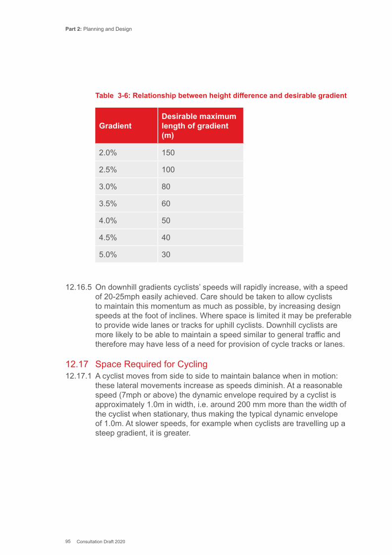
Part 2: Planning and Design
95 Consultation Draft 2020
GradientDesirable maximum length of gradient (m)
2.0% 150
2.5% 100
3.0% 80
3.5% 60
4.0% 50
4.5% 40
5.0% 30
Table 3-6: Relationship between height difference and desirable gradient
12.16.5 On downhill gradients cyclists’ speeds will rapidly increase, with a speed of 20-25mph easily achieved. Care should be taken to allow cyclists to maintain this momentum as much as possible, by increasing design speeds at the foot of inclines. Where space is limited it may be preferable to provide wide lanes or tracks for uphill cyclists. Downhill cyclists are more likely to be able to maintain a speed similar to general traffic and therefore may have less of a need for provision of cycle tracks or lanes.
12.17 Space Required for Cycling12.17.1 A cyclist moves from side to side to maintain balance when in motion:
these lateral movements increase as speeds diminish. At a reasonable speed (7mph or above) the dynamic envelope required by a cyclist is approximately 1.0m in width, i.e. around 200 mm more than the width of the cyclist when stationary, thus making the typical dynamic envelope of 1.0m. At slower speeds, for example when cyclists are travelling up a steep gradient, it is greater.
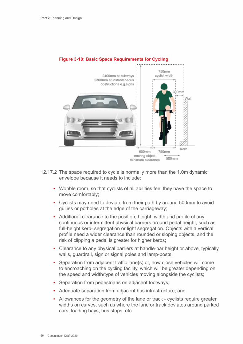
Part 2: Planning and Design
96 Consultation Draft 2020
Figure 3-10: Basic Space Requirements for Cycling
12.17.2 The space required to cycle is normally more than the 1.0m dynamic envelope because it needs to include:
▪ Wobble room, so that cyclists of all abilities feel they have the space to move comfortably;
▪ Cyclists may need to deviate from their path by around 500mm to avoid gullies or potholes at the edge of the carriageway;
▪ Additional clearance to the position, height, width and profile of any continuous or intermittent physical barriers around pedal height, such as full-height kerb- segregation or light segregation. Objects with a vertical profile need a wider clearance than rounded or sloping objects, and the risk of clipping a pedal is greater for higher kerbs;
▪ Clearance to any physical barriers at handle-bar height or above, typically walls, guardrail, sign or signal poles and lamp-posts;
▪ Separation from adjacent traffic lane(s) or, how close vehicles will come to encroaching on the cycling facility, which will be greater depending on the speed and width/type of vehicles moving alongside the cyclists;
▪ Separation from pedestrians on adjacent footways; ▪ Adequate separation from adjacent bus infrastructure; and ▪ Allowances for the geometry of the lane or track - cyclists require greater
widths on curves, such as where the lane or track deviates around parked cars, loading bays, bus stops, etc.
Part 2: Planning and Design
97 Consultation Draft 2020
12.18 Widths for Cycle Tracks12.18.1 A clearance of 0.5m between dynamic envelopes enables cyclists to
pass or ride alongside one another comfortably and safely. Based on the typical dynamic envelope of 1.0m, this would mean that an effective width of 2.5m is required to permit safe overtaking or social cycling. A width of 2.0m allows these activities to take place with care and should therefore be regarded as a desirable minimum on routes designed for one-way cycling. It should be noted that, with a lane or track width of 2.5m, many non-standard cycles cannot overtake or cannot be overtaken without difficulty.
12.18.2 When moving in opposing directions, there is a risk of head-on collisions, which can be severe if cyclists are moving at high speeds. At least 1.0m clearance between opposing flows of cyclists is recommended. This gives rise to a desirable minimum width requirement of 3.0m for two-way cycle tracks. This minimum width would allow overtaking or social cycling where there is a light flow in the opposing direction.
12.18.3 Shared footway/cycle surfaces are not generally recommended but can offer a practical solution in rural and suburban areas where pedestrian and cycle traffic is light. A minimum width of 3.0m is recommended where pedestrians and cyclists use the same surface.
12.18.4 A minimum width of 1.5m is required between bollards, chicane barriers or at gates to accommodate the full range of cycles and mobility scooters. Kissing gates should not be used on cycle tracks.
12.19 Widths for Cycle Lanes12.19.1 A width of 2.0m will accommodate all cycles and enable riders to avoid
gulleys and be a comfortable distance from adjacent motor traffic. 1.5m is the minimum desirable width for with-flow cycle lanes. 2.0m is the minimum desirable width for contraflow cycle lanes.
12.19.2 Narrow cycle lanes (<1.5m) should not generally be used as they can place cyclists in greater danger. There is evidence that the presence of the cycle lanes leads to closer overtaking by drivers (Parkin J & Meyers C, 2009) compared to roads with no lane.
12.19.3 As with any form of transport, people cycling may be travelling with someone else. Many people will wish to be able to cycle in comfort side by side, particularly in the case of parents accompanying children, or when they wish to safely overtake another cyclist. If the cyclists cannot overtake slower riders within a cycle track or a cycle lane they will risk cycling in the adjacent all-purpose carriageway.
Part 2: Planning and Design
98 Consultation Draft 2020
12.20 Additional Width Adjacent to Vertical Features12.20.1 The recommended additional space (measured from the wheel) required
to provide sufficient clearance to an adjacent upstand or vertical structure parallel to a cycle track/lane is:
▪ 250mm for kerbs under 50mm high; ▪ 500mm for kerbs over 50mm high; ▪ 750mm to sign posts and lamp columns; and ▪ 1000mm to continuous features such as walls, railings or bridge parapets.
12.21 Width Considerations for On-Carriageway Cycling12.21.1 In places where cyclists can be expected to share the road with other
users, the width of the road profile has a profound effect on cyclists’ comfort. Cyclists will feel uncomfortable if they sense that they are impeding motor traffic, while drivers may become impatient if they cannot easily overtake. This may in turn lead to closer overtaking manoeuvres, which are uncomfortable and potentially dangerous.
12.21.2 Designers should always be aware of the effect of their lane and carriageway width choices on cyclists, even if they are designing a route that has not been identified as an active travel route. The obligation for highway authorities to consider cyclists when discharging their general functions is discussed further in Chapter 18.
On Carriageway Cycling Technique12.21.3 National Standards Cycle Training in Wales provides three levels of skills,
from basic bike handling to riding on busy roads and junctions.
12.21.4 The training recommends cyclists to adopt two main riding positions when riding on carriageways - the primary and secondary positions (see Figure 3.11). Designers need to be aware of these riding positions and design on-carriageway cycle routes with them in mind. Table 5.2 provides guidance on when on-carriageway cycling is acceptable.
12.21.5 Cyclists are taught to ride in the secondary position, between 0.5-1.0m from the kerb, whenever it is safe and reasonable for them to do so, and it is safe for motor vehicles to pass them. This position ensures that they are far enough out to be able to avoid drains or debris but can also move in either direction to avoid surface hazards.
12.21.6 When the available width is insufficient for the cyclist to be passed safely (i.e with the clearances in 3.19), and on the approach to side
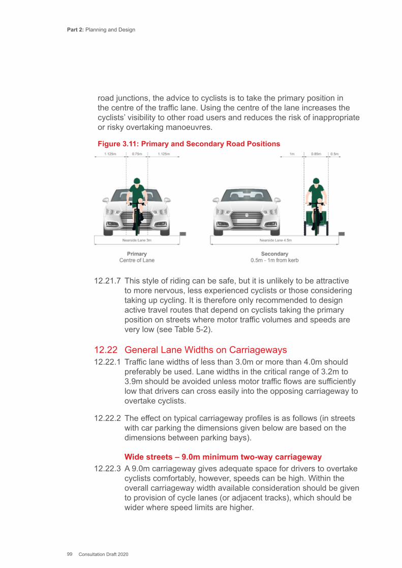
Part 2: Planning and Design
99 Consultation Draft 2020
road junctions, the advice to cyclists is to take the primary position in the centre of the traffic lane. Using the centre of the lane increases the cyclists’ visibility to other road users and reduces the risk of inappropriate or risky overtaking manoeuvres.
Figure 3.11: Primary and Secondary Road Positions
12.21.7 This style of riding can be safe, but it is unlikely to be attractive to more nervous, less experienced cyclists or those considering taking up cycling. It is therefore only recommended to design active travel routes that depend on cyclists taking the primary position on streets where motor traffic volumes and speeds are very low (see Table 5-2).
12.22 General Lane Widths on Carriageways12.22.1 Traffic lane widths of less than 3.0m or more than 4.0m should
preferably be used. Lane widths in the critical range of 3.2m to 3.9m should be avoided unless motor traffic flows are sufficiently low that drivers can cross easily into the opposing carriageway to overtake cyclists.
12.22.2 The effect on typical carriageway profiles is as follows (in streets with car parking the dimensions given below are based on the dimensions between parking bays).
Wide streets – 9.0m minimum two-way carriageway12.22.3 A 9.0m carriageway gives adequate space for drivers to overtake
cyclists comfortably, however, speeds can be high. Within the overall carriageway width available consideration should be given to provision of cycle lanes (or adjacent tracks), which should be wider where speed limits are higher.
Part 2: Planning and Design
100 Consultation Draft 2020
Critical width streets – 7.3m two-way carriageway12.22.4 The 7.3m carriageway has been the default standard in the UK for many
years, but this width often leads to unsuitable conditions for cycling and is not generally recommended for Active Travel Routes.
12.22.5 7.3m roads can provide reasonable space for drivers to overtake safely by crossing into the opposing lane if traffic volumes are low and sightlines are good. Where an existing 7.3m carriageway is being considered as an active travel route, it may be possible to make conditions more suitable for cycling by reducing the speed and volume of motor traffic or making the carriageway into a one-way road with two-way cycle lanes (2x2.0m cycle lanes plus 3.3m traffic lane).
12.22.6 On busier roads, drivers will often need to wait for gaps in oncoming traffic to safely pass cyclists, and some are tempted into close overtaking. Cyclists can feel intimidated by the vehicles waiting behind to pass them.
12.22.7 Designers should only use 7.3m wide carriageways for active travel routes when cyclists are accommodated off the carriageway or traffic volumes are low. Providing narrow (<1.5m) advisory cycle lanes within a 7.3m carriageway is not a recommended approach.
Narrow Streets12.22.8 Narrow streets are objectively safer for cyclists as drivers are less likely
to be able to overtake, and cyclists are able to be more assertive in their use of the space. However, such streets should be short, traffic calmed, and designed to make it clear that cyclists have priority.
12.23 Width at Pinch Points 12.23.1 It is important to ensure that chicanes and pinch-points have a bypass for
cycles or are designed in such a way that cyclists are neither squeezed nor intimidated by motor vehicles. The preferred option is to provide enough width so that a cyclist can remain in the secondary position and be overtaken safely. When speeds are low, the alternative is for cyclists to be automatically placed in the primary position by making the carriageway width less than 3.0m.
12.23.2 Table 3-7 shows that pinch points in the critical width range of between 3.1m and 3.9m should not be used. At this width drivers will be tempted to overtake cyclists with insufficient clearance.
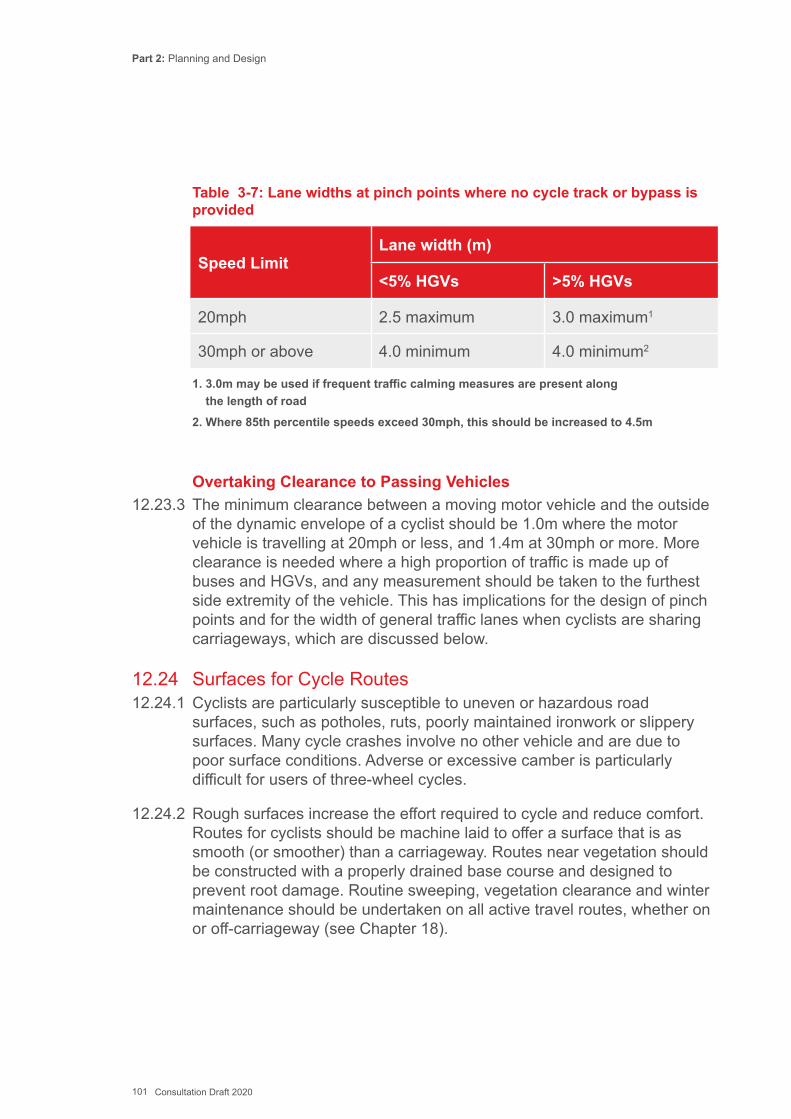
Part 2: Planning and Design
101 Consultation Draft 2020
Table 3-7: Lane widths at pinch points where no cycle track or bypass is provided
Speed LimitLane width (m)
<5% HGVs >5% HGVs
20mph 2.5 maximum 3.0 maximum1
30mph or above 4.0 minimum 4.0 minimum2
1. 3.0m may be used if frequent traffic calming measures are present along the length of road
2. Where 85th percentile speeds exceed 30mph, this should be increased to 4.5m
Overtaking Clearance to Passing Vehicles12.23.3 The minimum clearance between a moving motor vehicle and the outside
of the dynamic envelope of a cyclist should be 1.0m where the motor vehicle is travelling at 20mph or less, and 1.4m at 30mph or more. More clearance is needed where a high proportion of traffic is made up of buses and HGVs, and any measurement should be taken to the furthest side extremity of the vehicle. This has implications for the design of pinch points and for the width of general traffic lanes when cyclists are sharing carriageways, which are discussed below.
12.24 Surfaces for Cycle Routes12.24.1 Cyclists are particularly susceptible to uneven or hazardous road
surfaces, such as potholes, ruts, poorly maintained ironwork or slippery surfaces. Many cycle crashes involve no other vehicle and are due to poor surface conditions. Adverse or excessive camber is particularly difficult for users of three-wheel cycles.
12.24.2 Rough surfaces increase the effort required to cycle and reduce comfort. Routes for cyclists should be machine laid to offer a surface that is as smooth (or smoother) than a carriageway. Routes near vegetation should be constructed with a properly drained base course and designed to prevent root damage. Routine sweeping, vegetation clearance and winter maintenance should be undertaken on all active travel routes, whether on or off-carriageway (see Chapter 18).
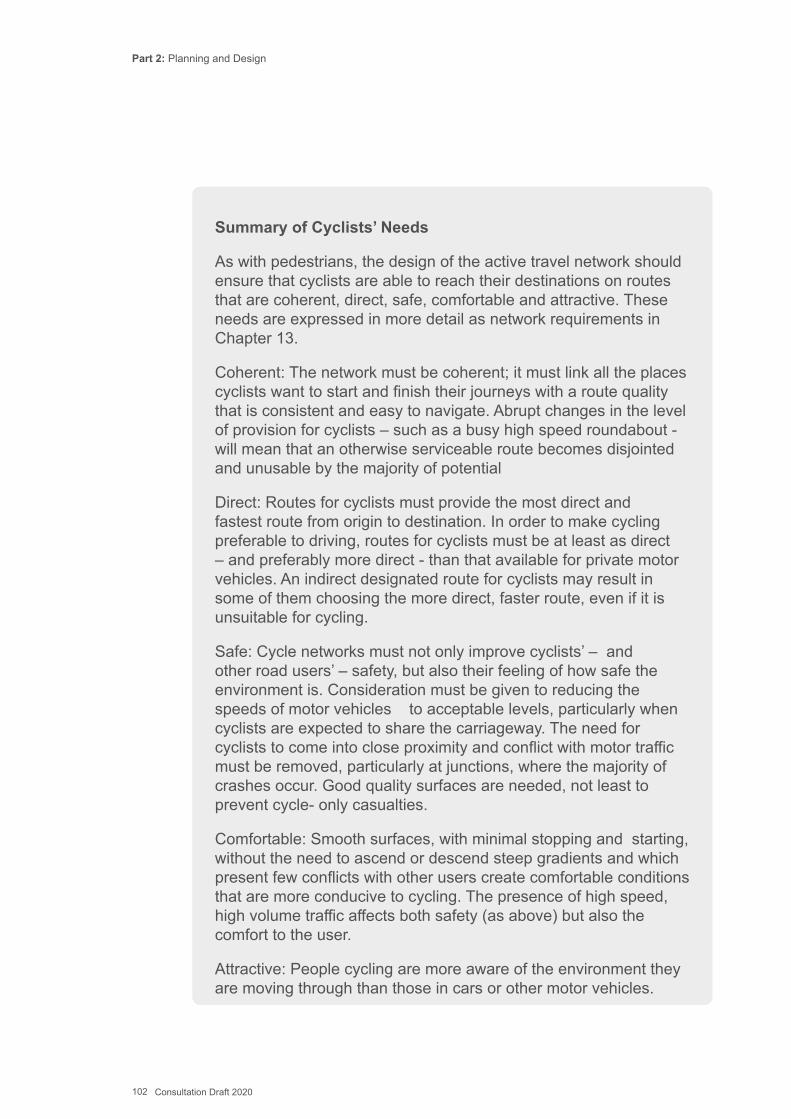
Part 2: Planning and Design
102 Consultation Draft 2020
Summary of Cyclists’ Needs
As with pedestrians, the design of the active travel network should ensure that cyclists are able to reach their destinations on routes that are coherent, direct, safe, comfortable and attractive. These needs are expressed in more detail as network requirements in Chapter 13.
Coherent: The network must be coherent; it must link all the places cyclists want to start and finish their journeys with a route quality that is consistent and easy to navigate. Abrupt changes in the level of provision for cyclists – such as a busy high speed roundabout - will mean that an otherwise serviceable route becomes disjointed and unusable by the majority of potential
Direct: Routes for cyclists must provide the most direct and fastest route from origin to destination. In order to make cycling preferable to driving, routes for cyclists must be at least as direct – and preferably more direct - than that available for private motor vehicles. An indirect designated route for cyclists may result in some of them choosing the more direct, faster route, even if it is unsuitable for cycling.
Safe: Cycle networks must not only improve cyclists’ – and other road users’ – safety, but also their feeling of how safe the environment is. Consideration must be given to reducing the speeds of motor vehicles to acceptable levels, particularly when cyclists are expected to share the carriageway. The need for cyclists to come into close proximity and conflict with motor traffic must be removed, particularly at junctions, where the majority of crashes occur. Good quality surfaces are needed, not least to prevent cycle- only casualties.
Comfortable: Smooth surfaces, with minimal stopping and starting, without the need to ascend or descend steep gradients and which present few conflicts with other users create comfortable conditions that are more conducive to cycling. The presence of high speed, high volume traffic affects both safety (as above) but also the comfort to the user.
Attractive: People cycling are more aware of the environment they are moving through than those in cars or other motor vehicles.
Part 2: Planning and Design
103 Consultation Draft 2020
Cycling is a pleasurable activity, in part because it involves such close contact with the surroundings. The attractiveness of the route itself will therefore affect whether users choose cycling.
How these principles are applied in planning networks and designing routes is covered in Chapters 13 and 14.
Key References for Cycle RoutesCROW (2016) Design Manual for Bicycle TrafficCycling Embassy of Denmark (2012) Collection of Cycle Concepts Davies DG et al. (2003) Cycling in Vehicle Restricted Areas: TRL583 Department for Transport. (2013a) ATT0321: Confidence cycling on the roadsDepartment for Transport (2013b) RAS20006: Vehicles involved in reported accidents by junction type, vehicle type, built-up and non built-up roads, Great BritainDepartment for Transport (2013c) RAS54004: Estimates of the annual non-fatal road casualties in Great Britain using National Travel Survey data compared with casualties recorded in STATS19 (2008/12)Department for Transport (2013d) Transport Statistics Great Britain 2013Knowles J et al (2009) Collisions involving pedal cyclists on Britain’s roads: establishing the causes, TRL PPR445Parkin J & Meyers C (2010) ‘The effect of cycle lanes on the proximity between motor traffic and cycle traffic.’ Accident Analysis and Prevention. 2010 Jan;42(1):159-65.
Part 2: Planning and Design
104 Consultation Draft 2020
This chapter sets out the value of producing Active Travel Network Map (ATNM) as required by the Active Travel Act. It focuses on the identification of improved active travel routes and facilities, of relevance to Section 1(b) of the Active Travel Act:
b) for approved Active Travel Network Maps of the new and improved active travel routes and related facilities needed to create integrated networks of active travel routes and related facilities in a local authority’s area.
13.1 Introduction13.1.1 Information relating to the legislation and process for producing and
submitting Active Travel Network Maps (ATNMs) is described in the Part 1: Delivery. The Act requires existing and proposed routes to be mapped on the ATNM. These routes could be on road, shared, segregated, or traffic-free. They can be for walkers or cyclists, or both. They will also show crossing points and the facilities that exist to support active travel on these routes, including cycle shelters/parking/storage, public toilets. Other facilities that could be usefully shown on the map include: seating, cycle hire locations and e-bike charging points. Existing routes that do not meet the standards set out in this Guidance will need to be accompanied by a statement setting out the extent to which they deviate from the guidance
13.1.2 Local authorities should also consider showing landmarks and destination points as appropriate. This will help facilitate journeys to these locations and provide reference points to make the maps easier to use. These destination points could include:
▪ main office locations and business parks; ▪ public transport nodes; ▪ libraries; ▪ post offices; ▪ sports stadiums; ▪ leisure centres; ▪ parks; ▪ religious buildings; ▪ hospitals;
Chapter 13: Network Planning
Part 2: Planning and Design
105 Consultation Draft 2020
▪ shopping centres; ▪ educational establishments; ▪ cultural institutions; ▪ tourist advice centres; ▪ tourist and leisure attractions; ▪ recreational walking and cycling routes; ▪ cycle maintenance and repair shops.
13.1.3 It is for the local authority to determine which, if any, locations would make the maps of most value to active travellers in their area.
13.1.4 The features that should be shown on the ATNM are listed below, but a local authority may elect to show additional features to improve the clarity of the map (see also 13.2.4):
▪ pedestrian area; ▪ pedestrian area where cycling is permitted; ▪ shared space areas; ▪ traffic free footpath; ▪ traffic free cycle path; ▪ traffic free shared use path; ▪ traffic free segregated path; ▪ on road cycle route; ▪ one-way streets; ▪ road without pavement; ▪ roads where cycling is not permitted; ▪ crossing points for pedestrians; ▪ crossing points for cyclists; ▪ shared use crossing points; ▪ level crossings.
13.1.5 The maps should also indicate if any of the following characteristics apply to these pieces of infrastructure:
▪ Steep gradients that make it difficult to walk or cycle; ▪ Places that have no streetlights;
Part 2: Planning and Design
106 Consultation Draft 2020
▪ Places that are not accessible at all times (e.g. gated at night); ▪ Access barriers (e.g. K-gates, stiles, bollards, steps) which prevent
infrastructure being fully accessible; ▪ Places where widths for pedestrians or cyclists are less than minimum
specified in Design Guidance.
13.1.6 This design guidance includes advice on planning cycling and walking networks, audit tools to help decide whether a route is appropriate for active travel as well as advice on selection of different types of infrastructure. Chapter 14 describes the differences in design requirements for walking and cycling, but there are also differences when planning pedestrian and cycle networks.
13.1.7 For clarity of presentation, separate methods are given for planning walking and cycling networks, but in practice data gathering and public consultation is common to both modes. Authorities should consider when to carry out the planning tasks separately for walking and cycling, and when to deal with both modes together. Both modal networks should be based on evidence of travel demand.
13.1.8 Cycling infrastructure is usually based around the development of route networks covering a whole town or city, as the upper limit for most utility cycle journeys extends to ten kilometres. Existing cycle infrastructure is often of poor quality or not provided at all.
13.1.9 The majority of walking trips stages are under 4 kilometres. Routes within Welsh settlements have typically evolved over a long period of time and may not always meet modern design standards. Footways adjacent to roads, as well footpaths away from roads, mean that in many places there is already a comprehensive network to accommodate most pedestrian trips. However, the quality can often be improved to make places that are safer and more accessible to all and thereby encourage active travel to and within the areas that attract lots of short journeys.
13.1.10 Network planning also needs to be adaptable to settlements of different sizes and demographics, which will in turn impact on the breadth of data required.
13.1.11 Local user knowledge is a key source of information and inputs from relevant stakeholders should be sought at all stages of the process using the techniques described in Chapter 20 and the processes described in Chapter 6 of Part 1: Delivery.
Part 2: Planning and Design
107 Consultation Draft 2020
13.2 Showing the Existing Routes on the Active Travel Network Map13.2.1 Full guidance on what is required by the Act is included in 5.6 of Part 1:
Delivery. The purpose of mapping Existing Routes is to communicate where routes are already available and suitable for active travel and to identify sections of those routes that require further investment and improvement.
13.2.2 The process of mapping the existing routes helps to establish a clear understanding of the local infrastructure, including gaps in existing provision and routes or sections that do not currently provide adequate design standards for all users.
13.2.3 The first step is to undertake an audit of existing routes. The audit records the conditions along the route, the levels of usage, the suitability for different types of users and statements on the nature and scale of any problems and potential improvements. The Route Audit Tools provided in Appendices B and C must be used to record how well a route meets the user needs described in Chapter 12.
13.2.4 Some routes will be different for pedestrians and cyclists, but some may be suitable for both – e.g. off-road, shared, and segregated or traffic free routes. The ATNMs should include road crossing points and other facilities that support active travel, including seating, cycle shelters/parking/ storage and public toilets.
13.3 Showing Proposed Routes on the Active Travel Network Map13.3.1 The purpose of showing the Future Routes on the ATNM is to identify
where new and improved routes are needed to create networks of the required standard for active travel. Existing plans and strategies that the local authority has already produced can be used to inform the creation of the Future Routes.
13.3.2 The ATNMs are intended to form part of strategic local transport and land use plans, provide evidence for bidding for funding and for developing work programmes.
13.3.3 The ATNM enables engagement with people needed to make the networks a reality - politicians, engineers, funding bodies and the public, as well as partners in health, education, commercial and voluntary bodies. Engagement helps to foster a sense of ownership of the plan both within the local authority and among the local public.
13.3.4 The ATNM is critical to the later design of route sections by providing the designer with an understanding of the context of a link or junction and its function with respect to the overall network
Part 2: Planning and Design
108 Consultation Draft 2020
13.3.5 The ATNM enables future improvement programmes to be planned, prioritised and managed. This represents a shift from ad-hoc opportunistic provision for cycling and walking, instead working towards development of a logical and comprehensive network for active travel
13.3.6 The ATNM enables authorities to consider potential sources of funds and make efficiencies by using overlaps with programmes across departments. As discussed further in Chapter 18, highway maintenance resurfacing could for example be used to alter road markings to create better cycle infrastructure, new pedestrian/cycle crossings could be installed as part of a road safety junction improvement scheme
13.3.7 The ATNM may also highlight potential for delivery of active travel schemes through non-highway functions, such as public realm and environmental management projects and new developments, including developer contributions (S278, S106 agreements and Community Infrastructure Levy funding). Development control officers should take the ATNM into account when considering planning applications, where existing or proposed routes pass through the site and to encourage new active travel trips.
13.4 Integration with Policies, Plans, Programmes and Infrastructure13.4.1 Integration is key to the successful delivery of active travel networks.
The programme of Active Travel infrastructure improvements needs to be integrated with existing functions of the urban network, and with other strategic plans and traffic management measures.
13.4.2 Good quality routes “complemented by other measures such as ample bike parking, integration with public transport, the education and training of cyclists and motorists, and a wide range of promotional events intended to generate enthusiasm and wide public support for cycling” (Pucher & Buehler, 2008, pp 495) is integral to achieving high levels of walking and cycling. The most successful infrastructure is delivered within a wider programme that includes political commitment, skilled delivery teams, engagement, encouragement and promotion (Cycling England, 2010). A list of potential policy and planning areas to consider is included in Chapter 2 of Part 1: Delivery.
13.4.3 This is an opportunity to consider relevant plans, and how they will come together to improve rates of walking and cycling across the local authority area. Individual schemes that were intended for delivery along the same route might be rationalised into a single scheme, for example. The Active Travel Network Map can then indicate where planned interventions might contradict each other or render schemes obsolete (for example,
Part 2: Planning and Design
109 Consultation Draft 2020
plans to restore gates on a footpath, which is also targeted to be turned into a cycle path with no gates). Particular attention should be paid to plans that will lead to changes in travel patterns, such changes afford significant opportunities for modal shift if appropriate infrastructure is available. Thus, plans for new schools, new housing developments, new workplaces need to be a major consideration in creating and reviewing the Active Travel Network Map.
13.4.4 The documents, plans, audits and other sources of information to consider in this process in this process should include:
▪ Strategic Development Plans ▪ Local Development Plans (and supplementary planning guidance); ▪ Local Transport Plans; ▪ Rights of Way Improvement Plans; and ▪ Wales Transport Strategy and National Transport Finance Plan
13.4.5 It could include other appropriate sources such as:
▪ local road safey plans and strategies, local well-being plans, proposals for land-use, including housing/regeneration/commercial/industrial/education/green spaces and other relevant developments.
13.4.6 This list is not exhaustive, and some of the plans mentioned above will not be relevant for all local authorities. The key point is to draw together existing plans and look for ways to maximise benefits across different policy objectives and to minimise duplication of effort where work has already been undertaken.
13.4.7 Modal Integration: When measures have been discussed for one transport mode, the consequences for other transport modes then become clearer. This integration is of most relevance where the different transport modes interact with one another such as at junctions and interchanges.
13.4.8 Land Use Integration: The effectiveness of the ATNM can be reinforced through integration with land use policy that creates developments that are conducive to active travel, and through a range of measures to encourage active travel as part of healthy lifestyles.
Part 2: Planning and Design
110 Consultation Draft 2020
13.5 Network Planning for WalkingOverview
13.5.1 There is usually already an extensive network of available routes to accommodate most pedestrian journeys and the process starts by reviewing and mapping existing routes. The role of pedestrian network planning for utility trips in built-up areas is generally not to provide new walking routes but to identify and prioritise improvements to make walking easier, safer and more attractive.
13.5.2 An overview of the process is summarized in the flow chart in Figure 4.1.
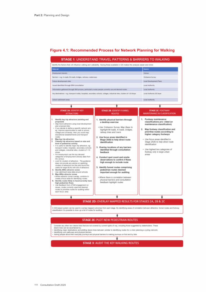
Part 2: Planning and Design
111 Consultation Draft 2020
Figure 4.1: Recommended Process for Network Planning for Walking
Part 2: Planning and Design
112 Consultation Draft 2020
13.5.3 Stage 1 is to identify where local short trips are taking place, and to gather and analyse any data that is available about the pattern and magnitude of the trips. The initial analysis and local engagement undertaken when looking at existing routes may have help identify local barriers to walking. Although specific data on pedestrian journeys may be scant, there may be more general information about local trip patterns such as Census Journey to Work data and school travel plan data, as well as cordon counts. Combining various pieces of information in GIS can help to start to build up a picture of local movements and which areas have high potential for more walking and/or issues to address.
13.5.4 Stage 2a is the further development of ideas through mapping the location of local trip attractors and considering their catchments, including the potential impact of new development proposals on local travel patterns. Part 1: Delivery provides examples of destination points that may be considered key walking trip attractors (town centre, stadia, rail stations etc).
13.5.5 Stage 2b is the identification of ‘funnel routes’ which are the key locations such as bridges, major road crossings and streets where pedestrian movements become concentrated.
13.5.6 Stage 2c. Where available, a footway maintenance classification may already exist, based on the relative local importance of routes, and this may also be used as a guide to key locations for walking. The guidance document ‘Well-Maintained Highways: Code of Practice for Highway Maintenance Management’ (RLG, 2005 Edition (2013 update)) provides five broad categories for classifying the functionality and scale of use for routes, as reproduced in Table 4-1.
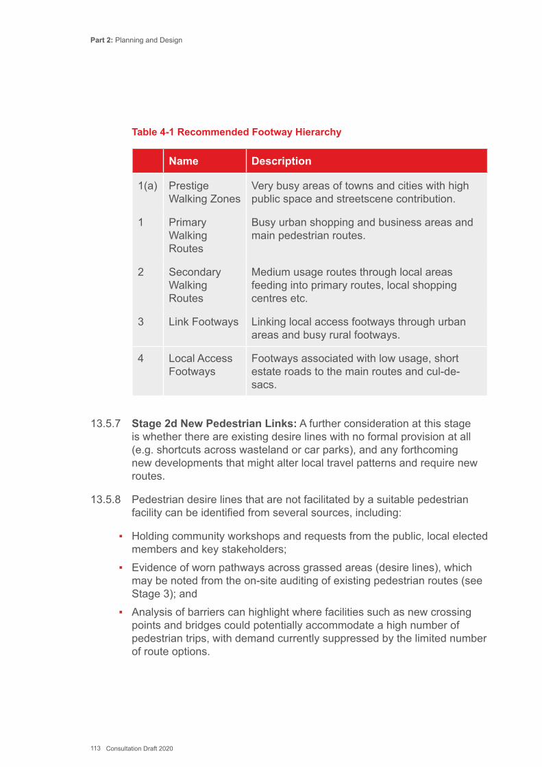
Part 2: Planning and Design
113 Consultation Draft 2020
Table 4-1 Recommended Footway Hierarchy
Name Description
1(a) Prestige Walking Zones
Very busy areas of towns and cities with high public space and streetscene contribution.
1 Primary Walking Routes
Busy urban shopping and business areas and main pedestrian routes.
2 Secondary Walking Routes
Medium usage routes through local areas feeding into primary routes, local shopping centres etc.
3 Link Footways Linking local access footways through urban areas and busy rural footways.
4 Local Access Footways
Footways associated with low usage, short estate roads to the main routes and cul-de-sacs.
13.5.7 Stage 2d New Pedestrian Links: A further consideration at this stage is whether there are existing desire lines with no formal provision at all (e.g. shortcuts across wasteland or car parks), and any forthcoming new developments that might alter local travel patterns and require new routes.
13.5.8 Pedestrian desire lines that are not facilitated by a suitable pedestrian facility can be identified from several sources, including:
▪ Holding community workshops and requests from the public, local elected members and key stakeholders;
▪ Evidence of worn pathways across grassed areas (desire lines), which may be noted from the on-site auditing of existing pedestrian routes (see Stage 3); and
▪ Analysis of barriers can highlight where facilities such as new crossing points and bridges could potentially accommodate a high number of pedestrian trips, with demand currently suppressed by the limited number of route options.
Part 2: Planning and Design
114 Consultation Draft 2020
13.5.9 Stage 2e involves overlaying all the information gathered onto a map. GIS provides one of the easiest ways to combine the various data sources and present the spatial information.
13.5.10 Public consultation (see Chapter 11 and Chapter 6 of Part 1: Delivery) is an important element of Stage 2, enabling planners to benefit from local knowledge about barriers and opportunities, and to get an understanding of the relative importance of different issues and potential support/opposition for interventions.
13.5.11 Housing and employment growth, and new transport hubs will alter walking patterns over time and bring opportunities to extend or improve the network through development planning. Land use development sites should therefore be considered during this stage (and in the document review outlined in Appendix L).
13.5.12 Stage 3 – Audit the routes: Once the review of documents, data and spatial information is complete, together with intelligence from the consultation process, an initial audit of the main routes (Primary and Secondary routes in Table 4-1) can be done to ascertain what improvement work is required (see Appendix G). At this stage, the audit is primarily concerned with identifying the nature of the issue and likely feasibility or scale of works required to meet the Active Travel design standard. It does not need to propose design solutions. The audit process can be quite resource intensive due to the varying conditions encountered along any given street or path. Auditors should be mindful of temporary issues such as inconsiderate parking, and whether the solution needs new infrastructure or simple enforcement.
13.5.13 The walking audit tool should be used, based on quantitative data (e.g. traffic counts and speed surveys), as the primary method of identifying the quality of the infrastructure. A potential Active Travel Route should achieve a minimum of 70% and a desirable score of 80%. Routes which score between 60% and 70% may still be included on the maps when accompanied by a suitable statement or explanation which justifies why they should be considered an active travel route (see Chapter 5 of Part 1: Delivery) or to be omitted from the ATNM if no improvement work is to be planned
Part 2: Planning and Design
115 Consultation Draft 2020
13.5.14 Additional audit tools could be used where appropriate to provide context and to take account of stakeholder views during scheme specific designs. There are several other methods for auditing walking infrastructure, ranging from detailed street audits, to surveys that only consider specific aspects of the infrastructure (such as footway condition surveys). The auditing methodology should target the key design considerations for pedestrian infrastructure.
▪ Comfort; ▪ Attractiveness; ▪ Accessibility; ▪ Directness; and ▪ Safety.
13.5.15 The checklist substitutes accessibility for coherence since usually the walking network is already reasonably comprehensive, however, the standard of infrastructure may mean that a route is not accessible.
13.5.16 Authorities can tailor the audit process to their local situation, considering the nature and scale of improvement schemes that they would be looking to propose, and the resources they have available to carry out the work. It may be appropriate to undertake detailed street audits if the extents of the pedestrian environment to be assessed are manageable, or to simply adopt a red, amber, green score for routes to quickly highlight places that need an improvement measure.
13.5.17 In order to ensure that the methodology for auditing existing infrastructure accounts for the views of different user groups, it may be useful to undertake a pilot street audit with representatives from the various user groups, including people with different types of disabilities. This information can form the basis of the Statement and Explanation, required to accompany any routes on the existing route map that are not up to standard, but suitable for mapping none the less. Part 1: Delivery contains more information about the statement and explanation.
13.5.18 Stage 4 – Scheme Identification: Where several small schemes have been identified within the same zone, or on the same route, it may be appropriate to merge the schemes into a package of works, to help ensure that individual measures are implemented together and achieve complementary benefits and synergies.
Part 2: Planning and Design
116 Consultation Draft 2020
13.5.19 It may be necessary to prioritise improvement schemes (and packages of schemes) for funding and implementation – this is a matter for local discretion. However, relevant factors to consider in prioritising pedestrian improvements include:
▪ The current and potential levels of pedestrian movements; ▪ Previous, current and planned levels of investment in the public realm; ▪ Integration with facilities for other transport modes, particularly cycling
and public transport; ▪ Performance against local transport policy objectives; ▪ Scheme feasibility / deliverability; ▪ Potential to attract funding, particularly private sector funding; and ▪ Implementation costs.
13.5.20 Stage 5: Prioritisation, Phasing & Active Travel Network Map. The settlements covered by the Act range in size from villages to large cities, and as such the number of pedestrian routes to be assessed will vary substantially. It is acknowledged that local authorities are unlikely to have the resources to audit, assess and identify improvements across a whole settlement in one phase, therefore some authorities will need to prioritise or phase the assessment work by dividing settlements into sub-areas. There is further advice on prioritization of planned improvements at the end of the cycling network section.
13.5.21 Stage 6 Monitoring: To establish the impact of any implemented walking improvements, monitoring of walking levels and travel patterns should be undertaken before and after implementation. The surveys and consultations undertaken to inform the development of the programme of works (see Stage 1) should provide a representation of existing ‘before’ walking patterns. Once the schemes that are to be implemented as part of the network planning assessment have been determined, and the geographic extents of implementation have been defined, the obtained information on views and perceptions regarding walking can be supplemented by pedestrian flow counts at key locations.
13.5.22 To best monitor the impact of implemented measures, ‘after’ surveys should be undertaken a suitable period after implementation. It is important that the brief for the ‘after’ surveys is consistent (through consideration of factors such as time, day of the week and weather conditions) with the ‘before’ surveys, to ensure that the results provide a direct comparison. Schemes funded by the Welsh Government will also have specific requirements in terms of post-completion monitoring arrangements.
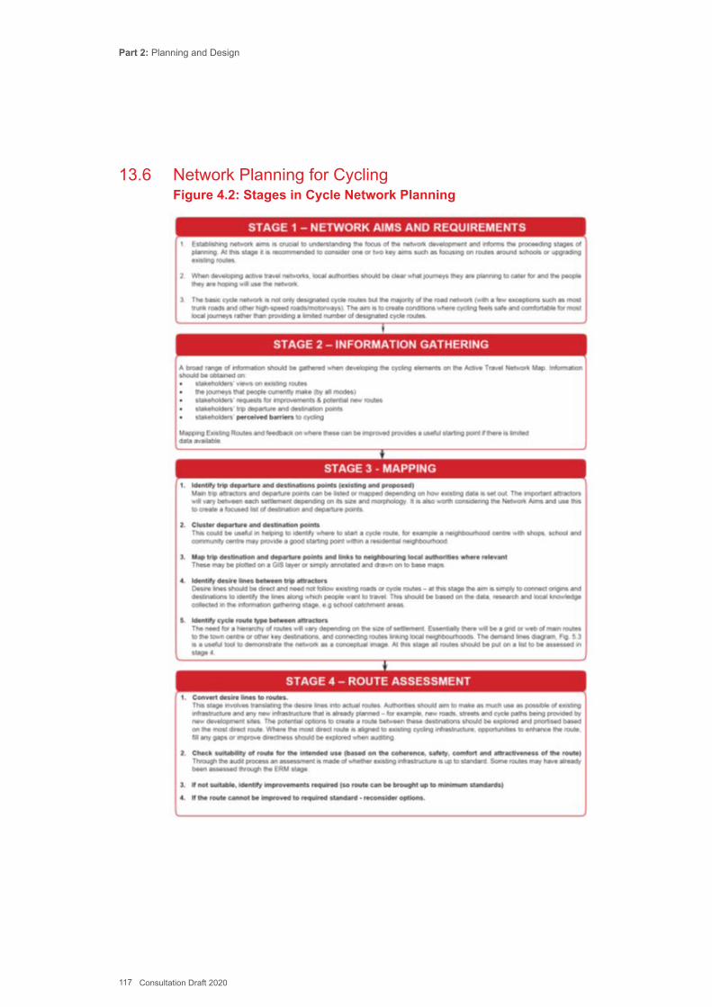
Part 2: Planning and Design
117 Consultation Draft 2020
13.6 Network Planning for CyclingFigure 4.2: Stages in Cycle Network Planning
Part 2: Planning and Design
118 Consultation Draft 2020
13.6.1 Stage 1: Network Aims and Requirements. Establishing network aims provides the focus for the network development and informs all the proceeding stages. Local authorities may choose to try to create an area wide local network, or to focus initially on serving key areas (such as links to a town centre) or types of journeys, such as travel to school. The network development will usually be linked to fulfilling other key policies and programmes described in the ‘integration’ Appendix L.
13.6.2 The Active Travel Act is aimed at promoting and enabling utility journeys, in particular to help reduce the number of short car journeys to access work, education, healthcare, retail, leisure or other services or destinations. Routes intended solely for recreation and tourism purposes are not part of the Active Travel Network.
13.6.3 If a cycle network is viewed as a grid or mesh that is laid across an area, and the designated routes are the lines of the mesh, then the density can be measured by the distance (typically crow-fly) between the designated routes. This distance between routes is referred to as the “mesh width” basis for network planning.
13.6.4 Networks developed under the Active Travel Act should aspire to have a mesh width of around 250m in central areas to create as dense a network of cycle routes as possible, while a wider mesh width of 500-1000m would be expected towards the outskirts of a town. The ATNMs set out the plans of the local authority for the next 15 years and are revised every three years to illustrate progress. Physical barriers such as hills, rivers and railway lines will also affect the potential mesh width but the ATNM should include any viable opportunities to address these.
13.6.5 Network Requirements. Important factors to creating a usable cycle network are explored in Chapter 12, User Needs. Routes should be:
▪ Coherent; ▪ Direct; ▪ Safe; ▪ Comfortable; and ▪ Attractive.
13.6.6 The first two of these factors (i.e. coherence, directness) are of importance in the planning of the overall cycle network, whereas safety, comfort and attractiveness play more of a role in scheme design. Safety is important in network planning, but many safety issues can be addressed through careful design.
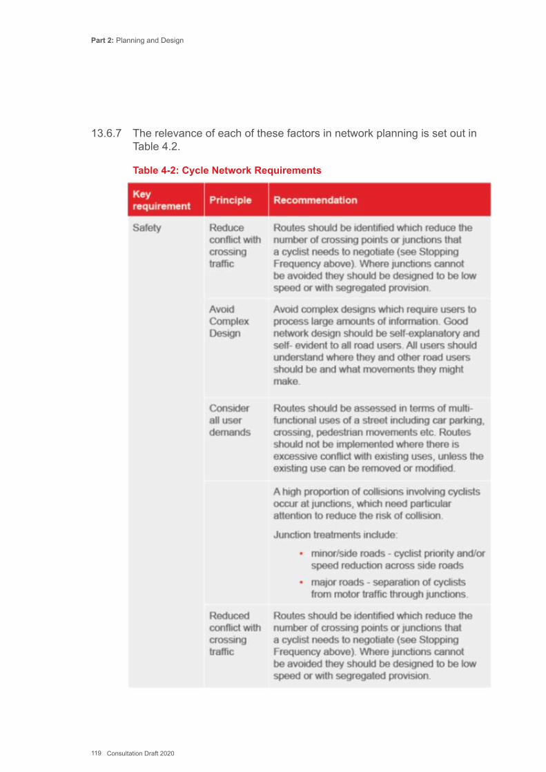
Part 2: Planning and Design
119 Consultation Draft 2020
13.6.7 The relevance of each of these factors in network planning is set out in Table 4.2.
Table 4-2: Cycle Network Requirements
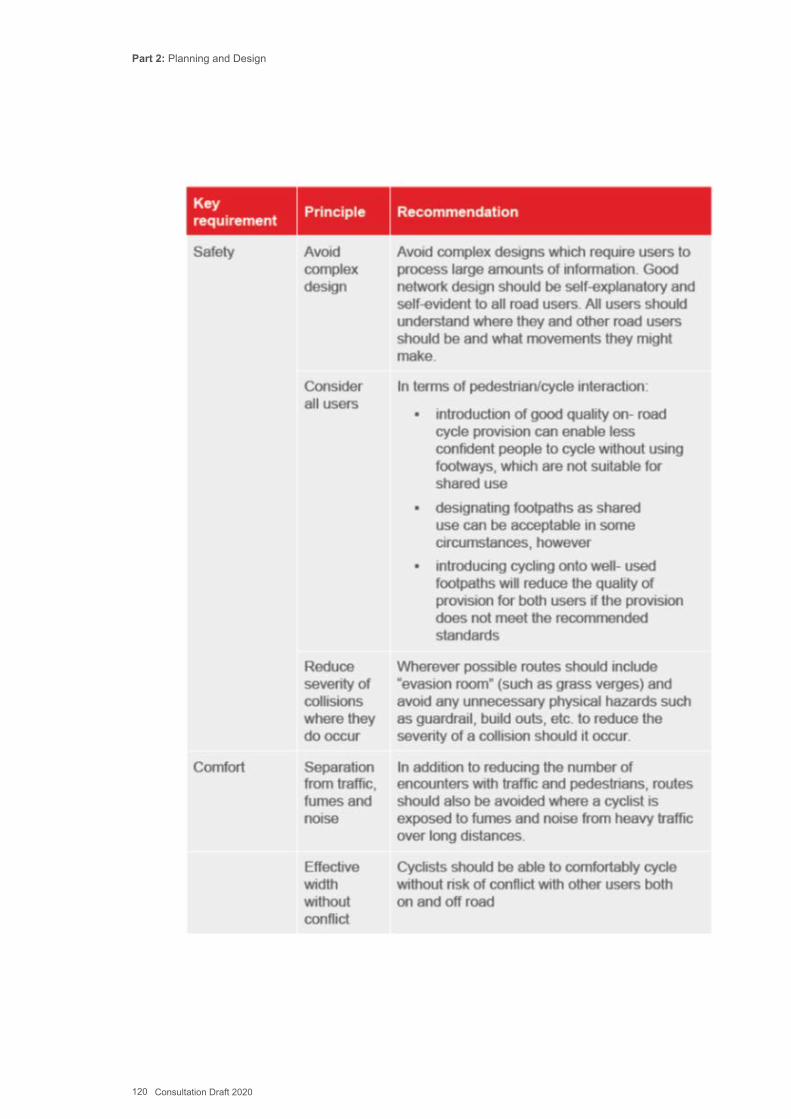
Part 2: Planning and Design
120 Consultation Draft 2020
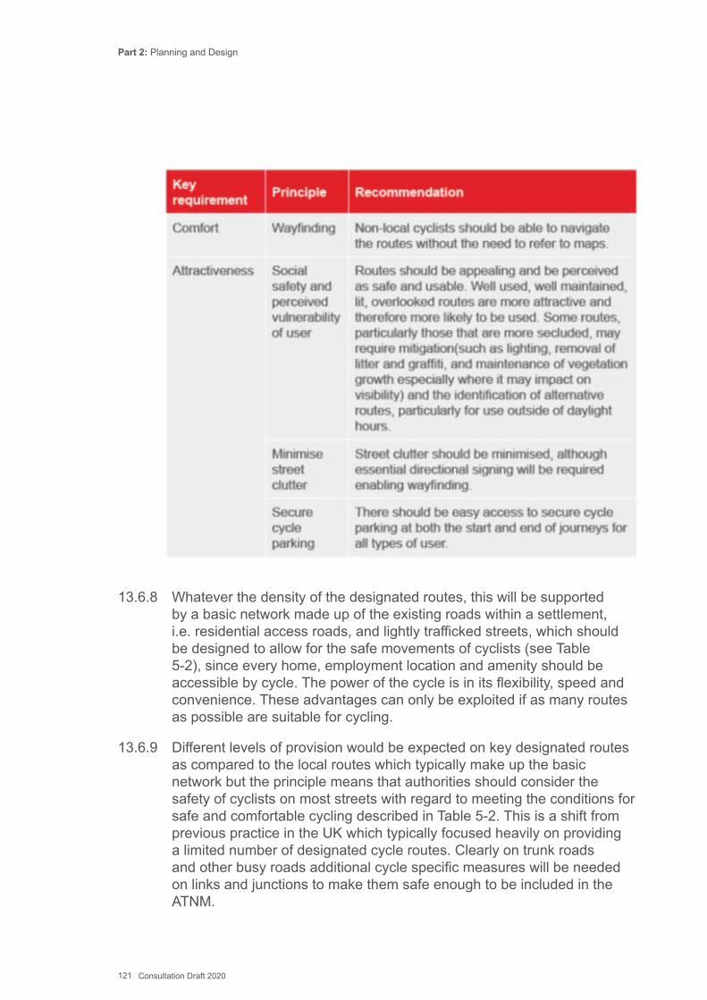
Part 2: Planning and Design
121 Consultation Draft 2020
13.6.8 Whatever the density of the designated routes, this will be supported by a basic network made up of the existing roads within a settlement, i.e. residential access roads, and lightly trafficked streets, which should be designed to allow for the safe movements of cyclists (see Table 5-2), since every home, employment location and amenity should be accessible by cycle. The power of the cycle is in its flexibility, speed and convenience. These advantages can only be exploited if as many routes as possible are suitable for cycling.
13.6.9 Different levels of provision would be expected on key designated routes as compared to the local routes which typically make up the basic network but the principle means that authorities should consider the safety of cyclists on most streets with regard to meeting the conditions for safe and comfortable cycling described in Table 5-2. This is a shift from previous practice in the UK which typically focused heavily on providing a limited number of designated cycle routes. Clearly on trunk roads and other busy roads additional cycle specific measures will be needed on links and junctions to make them safe enough to be included in the ATNM.
Part 2: Planning and Design
122 Consultation Draft 2020
13.6.10 The design principles in Chapter 12 should be applied to all new highway and development schemes to ensure that they are accessible by walking and cycling.
13.6.11 Stage 2: Information Gathering. A broad range of information should be gathered when developing the cycling elements on the ATNM. The need for this will depend to some extent on the size of the settlement, but collecting more information is likely to increase the quality of the final network and therefore the take-up active travel.
13.6.12 Information should be obtained on:
▪ The journeys that people currently make (by all modes of transport); ▪ Their trip departure and destination points; ▪ The barriers they perceive to cycling or cycling more often; ▪ Their views on existing routes; and ▪ Their requests for improvements and potential new routes.
13.6.13 This information can be gathered through a variety of means including surveys, workshops, social media and exhibitions, both on-street and in nearby buildings. Local authorities could undertake surveys of the public’s expectations and requirements for walking and cycling routes and facilities. This should include a broad spectrum of people, not just those with an interest in active travel (see Chapter 11). This may include assessing the needs locally of specific user groups, such as disabled people. Surveys might also help to assess the extent to which people are making short car journeys due to a lack of knowledge of alternative methods, poor or missing infrastructure provision or because their journey was unsuitable for active travel. The requirements for consultation in preparing and submitting maps to Welsh Government are set out in Chapter 6 of Part 1: Delivery.
13.6.14 Sources of Data. There is a broad range of publicly available data which can usefully input into the development of an ATNM (included in Appendix L). Launched in Wales in Spring 2018, the National Propensity to Cycle Tool offers an easy way to look at local commuter trip patterns and also includes an assignment function that maps the trips to the local network (see http://pct.bike/ ).
13.6.15 Where necessary local authorities may need to carry out additional cycle and traffic counts or speed surveys on specific streets or routes where no data already exists. This needs to be used in the context of the existing and envisaged use by motor vehicles and cyclists and can also be used for future monitoring of the impact of improvements (see Chapter 13).
Part 2: Planning and Design
123 Consultation Draft 2020
13.6.16 Care needs to be taken to ensure that seemingly ‘safe’ routes with low casualty levels are not actually heavily trafficked routes that most cyclists avoid (and hence show very low casualty levels or a disproportionate relative risk to cyclists).
13.6.17 Stage 3 Mapping. Once the relevant information has been gathered the mapping stage can be undertaken. The mapping stage should be developed through a process of layering relevant information from various sources as listed in Appendix L. This is most easily done using GIS.
13.6.18 The mapping stage involves the following steps:
▪ Map trip departure and destination points; ▪ Plot links between them; and ▪ Designate route type.
13.6.19 Stage 3 Plot Trip Departure and Destination Points. Trip departure points are usually the main residential areas of the settlement. Depending on its size and the required density of the network, the departure points can be clustered – see below.
13.6.20 Trip destination points generally cover all of the buildings and amenities that might attract existing and potential cyclists.
13.6.21 For the Active Travel Act the important local departure and destination points will need to be completed as part of the production of the ATNM and should include town centres, public transport interchanges, major employment sites and so on (see paras 13.1.2 and 13.1.4). New planned developments should also be considered.
13.6.22 Local authorities should also consider destination and departure points in neighbouring local authorities where active travel is a viable transport option between different local authority areas. It is recommended that wherever possible settlements in different local authorities are connected through the active travel networks, which should be developed through collaborative working (Part1, 5.3).
13.6.23 Stage 3 Clustering of departure/destination points. Once all existing and proposed departure and destination points have been mapped they will usually need to be clustered to reduce the complexity of identifying desire lines.
13.6.24 The clustering will depend on the size of the settlement and the density of the network being developed. For larger towns and cities this clustering might be done by only including larger employment sites (e.g. where more than 100 people are employed) or only the larger shopping areas.
Part 2: Planning and Design
124 Consultation Draft 2020
13.6.25 For example, when developing the Cardiff strategic cycle network plan, homes within a neighbourhood were clustered and identified by one key point (e.g. the main hub or row of shops within the neighbourhood); and employment centres such as Cardiff Bay were identified as one key destination point.
13.6.26 The clustering undertaken for the initial trip analysis does not produce a fine grain network plan of a density of 250m mesh width. As the ATNM matures with future triennial submissions a closer mesh width can be identified and created until the desired density is achieved.
13.6.27 Stage 3 Identify Desire Lines. Once trip destination and departure points have been mapped, the next step involves plotting the desire lines between them. The desire lines should be direct and should not follow existing roads or cycle routes – all that is needed at this stage is to identify the corridors along which people want to travel. The ATNM is an invaluable tool when converting desire lines to actual routes, but the identification of desire lines should not be constrained by existing routes.
13.6.28 The identification of the desire lines should be based on the data, research and local knowledge collected in the information gathering and consultation stages. For example, not every residential area needs to be linked to every school as generally schools have local catchment areas (although this may not be applicable to Welsh language medium or religious schools) so only links within those catchment areas need to be considered. Census data can provide extensive information on residential and workplace populations which can be used to identify potentially useful links.
13.6.29 This methodology is scalable - a considerable amount of analysis may be appropriate to identify a complex cycle route network in a city but in smaller towns and villages the desire lines and improvement options may be obvious.
13.6.30 Stage 3 Consider Route Function and User Needs. Prior to converting the desire lines into actual routes, the importance of the route needs to be understood, in terms of the numbers and types of cyclists it will need to cater for (e.g. links to schools will need to cater for younger people’s needs).
13.6.31 This process informs the designation of route type. The route types are similar to the hierarchies used to identify different levels of service for motor traffic that would be expected on trunk roads, distributor roads and residential streets.

Part 2: Planning and Design
125 Consultation Draft 2020
13.6.32 The following classification of cycle routes is recommended. The routes are designated by the importance of the connections they make within the network, not by whether they are a cycle track, cycle lane, shared carriageway or greenway:
▪ Primary routes: The key corridors between neighbourhoods/ residential areas and a town or city centre; routes between districts and neighbourhoods; cycle routes which are (or will be) used by a great many cyclists. Links to main public transport interchanges.
▪ Secondary routes: The links between the primary routes; links to trip attractors such as schools, colleges, employment sites; cycle routes which are an attractor for a more limited range of users; routes which may cater for fewer cycle journeys than the primary routes but are still of strategic importance within the network. Links to local public transport interchanges and stops.
▪ Local routes: All other all-purpose roads, greenways and bridleways that are not necessarily part of a designated route (e.g. many residential streets). This basic network of local routes (see para 14.4), although lower in the hierarchy, forms an important part of the cycle network, providing secondary and tertiary routes connecting to the strategic routes.
13.6.33 Different thicknesses of line can be used to show the relative importance of the connections as in Figure 4.3.
Figure 4.3 Illustrative Demand Lines Diagram
LARGE BUSINESS
AREA
LARGE RESIDENTIAL
AREA
LARGE MARKET
SMALL BUSINESS
AREA
SMALL RESIDENTIAL
AREA
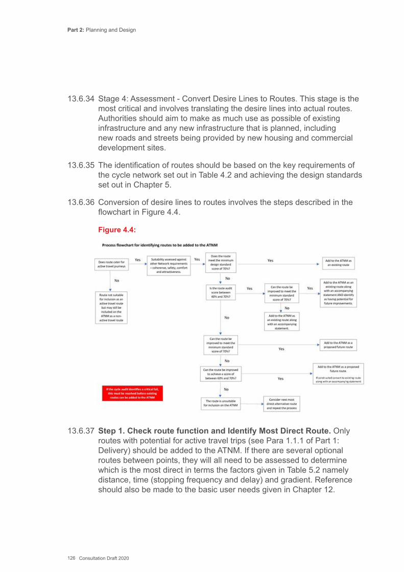
Part 2: Planning and Design
126 Consultation Draft 2020
13.6.34 Stage 4: Assessment - Convert Desire Lines to Routes. This stage is the most critical and involves translating the desire lines into actual routes. Authorities should aim to make as much use as possible of existing infrastructure and any new infrastructure that is planned, including new roads and streets being provided by new housing and commercial development sites.
13.6.35 The identification of routes should be based on the key requirements of the cycle network set out in Table 4.2 and achieving the design standards set out in Chapter 5.
13.6.36 Conversion of desire lines to routes involves the steps described in the flowchart in Figure 4.4.
Figure 4.4:
13.6.37 Step 1. Check route function and Identify Most Direct Route. Only routes with potential for active travel trips (see Para 1.1.1 of Part 1: Delivery) should be added to the ATNM. If there are several optional routes between points, they will all need to be assessed to determine which is the most direct in terms the factors given in Table 5.2 namely distance, time (stopping frequency and delay) and gradient. Reference should also be made to the basic user needs given in Chapter 12.
Part 2: Planning and Design
127 Consultation Draft 2020
13.6.38 Step 2. Check suitability of route. The most direct route should then be assessed in terms of the other key requirements of coherence, safety, comfort and attractiveness given in Table 5.2 and the design guidance and standards set out in Chapter 14.
13.6.39 Appendix H contains an Audit Tool for this task. It is intended to be used on-site and provide a means of ensuring that all factors which make up the key requirements are considered.
13.6.40 The desirable audit score is 80% or above, with a minimum score of 70% being required to confirm the route is suitable for active travel. A route that has any element that is marked as ‘Critical’ is not deemed suitable for active travel, however if the route can be improved to address a ‘Critical’ element then it can be included as a future route on the Active Travel Network Map. Routes with an audit score of between 60% and 70% may be included on the ATNM where they are accompanied by a supporting statement to justify their inclusion. Occasionally a route may be very close to the acceptable score but for one or two features that cannot be modified. In this case a justification for inclusion should be provided, along with evidence that it is acceptable to local stakeholders, when the map is submitted. A ‘Route Selection Tool’ has been developed for the English Department for Transport to help evaluate, illustrate and compare the strengths and weaknesses of alignments.
13.6.41 Step 3. Can the route feasibly be improved to meet the standards? If the route is not suitable in its current condition, an assessment should be undertaken to identify the works or measures that would enable it to fulfil the network requirements and the design standards. The audit process could then be repeated on the proposed design to see how this will affect the score. Feasibility should involve the following considerations:
▪ There is often more than one solution - options should be considered (and consulted on) to identify the best solution for all road users;
▪ Work towards the optimum solution for active travel, in line with the design principles - the aim is to make cycling and walking on active travel routes more inviting than using motor vehicles. People will only choose to walk or cycle if they gain from it personally;
▪ The existing motor traffic situation must be considered - This should be based on actual surveys and observations (of speed, volume, parking and loading demand, turning movements as applicable). It should not be assumed that traffic speeds and volumes are low in all residential streets. In congested situations or where there is kerbside activity, segregation may be required despite low speeds;
▪ Speeds and volumes of motor traffic on any route are not fixed - Can one or both can be reduced?
Part 2: Planning and Design
128 Consultation Draft 2020
13.6.42 A high proportion of collisions involving cyclists occur at junctions. Active travel networks should ensure that there are no gaps in provision along any part of a route. Junctions are given particular attention, as they often ‘unlock’ areas of quiet streets and connections to greenways. The following should be considered;
▪ speed reduction and legibility are crucial factors in improving safety for all users;
▪ junctions should be designed such that all users are aware of the potential positioning and movements of other users;
▪ visibility and eye contact can help different road users to communicate and improves safety;
▪ cyclists wherever possible should be given equal status and priority with motor traffic through priority over quieter side roads, cycle specific signals, increased green time on cycle routes (particularly on uphill gradients), toucan crossings, and junctions which reduce the speeds of all users to that similar to cyclists;
▪ conventional roundabouts often pose the highest risk to cyclists due to the speed differential and difficulty in road positioning.
▪ Multi-disciplinary design input - The best designs, particularly for complex transport problems are often identified through interactive sessions involving user groups, operators and designers.
13.6.43 Step 4. Reconsider options. If the preferred route cannot be brought up to an acceptable standard, or if the impacts on other road users are considered too onerous, what other route options are available?
13.7 Validation of Active Travel Network Maps13.7.1 Once the draft ATNMs have been produced, there should be further
engagement with both internal and external stakeholders to validate the proposals.
13.7.2 This consultation should be as extensive as possible to help ensure all those who may be affected by the proposals have a chance to input. For the ATNMs developed as part of the Act that there should be a 12-week public consultation. General advice on consultation techniques is included in Chapter 12 while the specific requirements for consultation are in Chapter 6 of Part 1: Delivery.
13.7.3 It is important to be clear in public consultation that the ATNMs show longer term aims and outline ideas. Consultation on the maps does not replace the need for consultation and negotiation on individual schemes as and when specific proposals for delivery / implementation are taken forward.
Part 2: Planning and Design
129 Consultation Draft 2020
13.8 Prepare and Submit Active Travel Network Map13.8.1 Following consultation, amendments are made to the Active Travel
Network Maps (for both walking and cycling improvements) prior to submission to the Welsh Ministers for approval.
13.8.2 Chapter 5 of Part 1: Delivery gives detail guidance on the submission, approval and review process.
13.9 Prioritising and Delivering the Active Travel Schemes13.9.1 Local authorities should decide for themselves how best to plan for
the delivery of their Active Travel upgrades over a fifteen- year period. The parts of the network that potentially offer the greatest impact on increasing rates of active travel (Part 1, 5.1.2 and 5.16.1) should be prioritised, but other local priorities may also be considered such as targeting areas of deprivation or poor public health. Local authorities should also be mindful of their duty to contribute to the achievement of the goals of the Well-being of Future Generations Act.
13.9.2 A data led approach can be used for prioritisation analysis and decision making about which schemes are most important to achieving the network aims or offer the best value for money. A scoring matrix to assist prioritisation of schemes identified in the ATNM, together with the associated scoring criteria, is included at Appendix M.
13.9.3 The advantage of using a prioritisation framework is that it brings some consistency to the assessment of schemes across a local authority area. In the absence of any existing methodologies, local authorities are encouraged to use the matrix at Appendix M to assist them to prioritise the development of active travel schemes in their area.
13.9.4 Factors such as level of available funding and the opportunities for ‘quick wins’ that demonstrate progress are also important in considering which schemes to take forward, as are the local politics that might decide the fate of a scheme proposal. Whilst larger and more complex schemes may have a long lead in due to the complexity of planning and design required, where they are prioritised these proposals should be designed and developed in parallel with the delivery of less complex schemes.
13.9.5 One of the advantages of the ATNM is the ability to deliver the network through a broader range of funding sources and not just through budgets specific to active travel. This includes opportunities to gain new routes and improvements through development control, but this will introduce dependencies on the timeline of the development to deliver network elements. It may however also open up ways for more ambitious long-term schemes to be planned and delivered as part of major redevelopment or highways schemes.
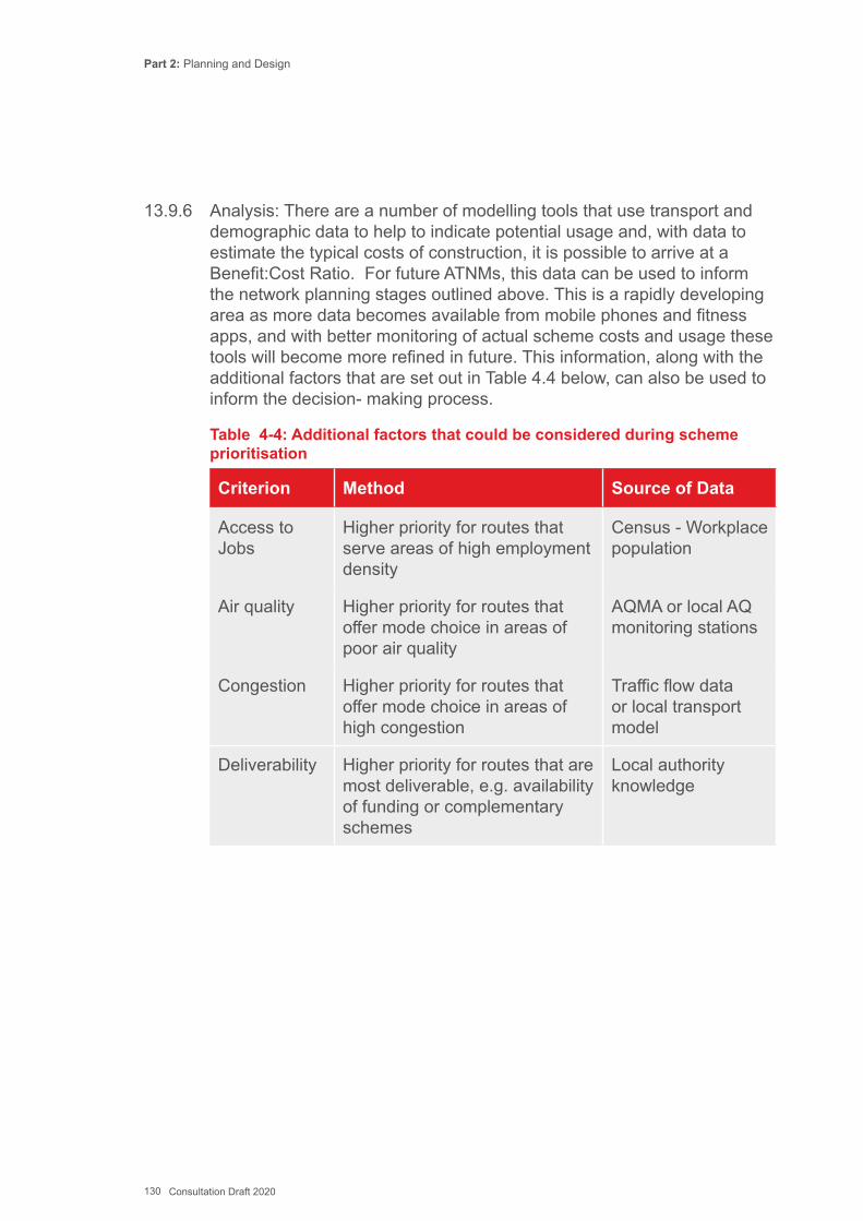
Part 2: Planning and Design
130 Consultation Draft 2020
13.9.6 Analysis: There are a number of modelling tools that use transport and demographic data to help to indicate potential usage and, with data to estimate the typical costs of construction, it is possible to arrive at a Benefit:Cost Ratio. For future ATNMs, this data can be used to inform the network planning stages outlined above. This is a rapidly developing area as more data becomes available from mobile phones and fitness apps, and with better monitoring of actual scheme costs and usage these tools will become more refined in future. This information, along with the additional factors that are set out in Table 4.4 below, can also be used to inform the decision- making process.
Table 4-4: Additional factors that could be considered during scheme prioritisation
Criterion Method Source of Data
Access to Jobs
Higher priority for routes that serve areas of high employment density
Census - Workplace population
Air quality Higher priority for routes that offer mode choice in areas of poor air quality
AQMA or local AQ monitoring stations
Congestion Higher priority for routes that offer mode choice in areas of high congestion
Traffic flow data or local transport model
Deliverability Higher priority for routes that are most deliverable, e.g. availability of funding or complementary schemes
Local authority knowledge
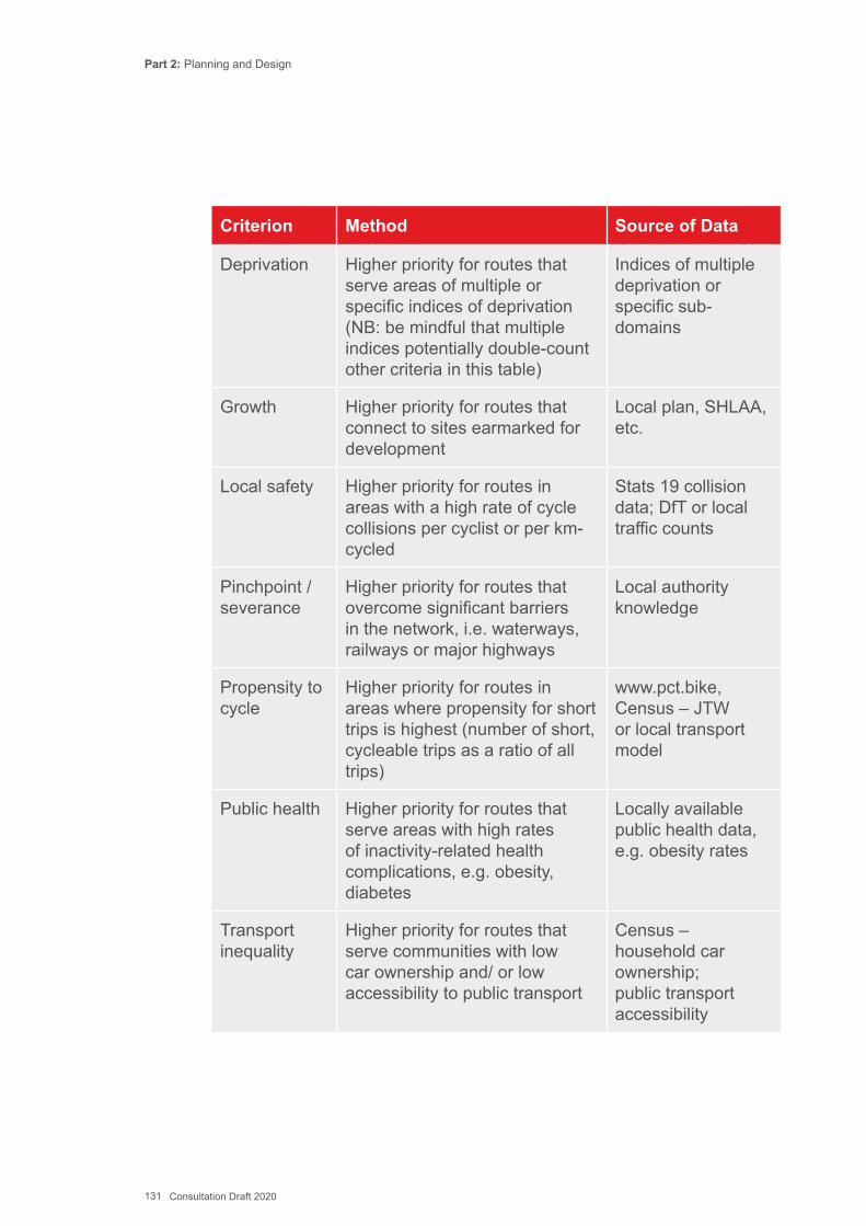
Part 2: Planning and Design
131 Consultation Draft 2020
Criterion Method Source of Data
Deprivation Higher priority for routes that serve areas of multiple or specific indices of deprivation (NB: be mindful that multiple indices potentially double-count other criteria in this table)
Indices of multiple deprivation or specific sub-domains
Growth Higher priority for routes that connect to sites earmarked for development
Local plan, SHLAA, etc.
Local safety Higher priority for routes in areas with a high rate of cycle collisions per cyclist or per km-cycled
Stats 19 collision data; DfT or local traffic counts
Pinchpoint / severance
Higher priority for routes that overcome significant barriers in the network, i.e. waterways, railways or major highways
Local authority knowledge
Propensity to cycle
Higher priority for routes in areas where propensity for short trips is highest (number of short, cycleable trips as a ratio of all trips)
www.pct.bike, Census – JTW or local transport model
Public health Higher priority for routes that serve areas with high rates of inactivity-related health complications, e.g. obesity, diabetes
Locally available public health data, e.g. obesity rates
Transport inequality
Higher priority for routes that serve communities with low car ownership and/ or low accessibility to public transport
Census – household car ownership; public transport accessibility
Part 2: Planning and Design
132 Consultation Draft 2020
Key ReferencesAldred, R (2012) Cycling cultures: summary of key findings andrecommendations. ESRC, UEL.Bristol City Council (2012) ‘20mph speed limit pilot areas’ - http://www. bristol.gov.uk/page/20mph-speed-limit-pilot-areas (Accessed 1st May 2012)Bristol City Council (2012b) 20mph Speed Limit Pilot Areas - Monitoring Report (March 2012)Carness, D (2000) Cycling and Health Promotion BMJ 2000;320:888 Department for Transport (2008) Cycle Infrastructure Design – LTN 2/08Department for Transport (2017) Local Cycling and Walking Infrastructure PlansDutch Ministry of Water, Energy and Transport (2009) Cycling-Inclusive Policy Development: A HandbookWarrington BC (2010) Executive Board 18 October 2010 (20mph Speed Limit Trial Assessment)
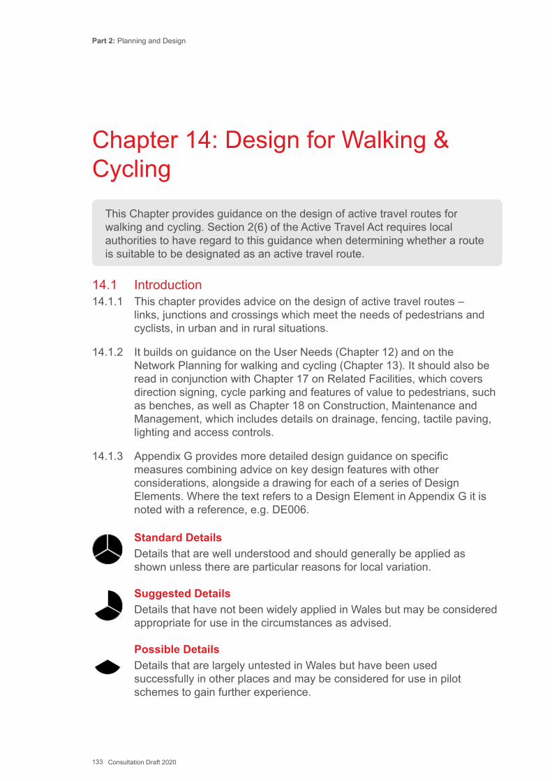
Part 2: Planning and Design
133 Consultation Draft 2020
14.1 Introduction14.1.1 This chapter provides advice on the design of active travel routes –
links, junctions and crossings which meet the needs of pedestrians and cyclists, in urban and in rural situations.
14.1.2 It builds on guidance on the User Needs (Chapter 12) and on the Network Planning for walking and cycling (Chapter 13). It should also be read in conjunction with Chapter 17 on Related Facilities, which covers direction signing, cycle parking and features of value to pedestrians, such as benches, as well as Chapter 18 on Construction, Maintenance and Management, which includes details on drainage, fencing, tactile paving, lighting and access controls.
14.1.3 Appendix G provides more detailed design guidance on specific measures combining advice on key design features with other considerations, alongside a drawing for each of a series of Design Elements. Where the text refers to a Design Element in Appendix G it is noted with a reference, e.g. DE006.
This Chapter provides guidance on the design of active travel routes for walking and cycling. Section 2(6) of the Active Travel Act requires local authorities to have regard to this guidance when determining whether a route is suitable to be designated as an active travel route.
Chapter 14: Design for Walking & Cycling
Standard Details Details that are well understood and should generally be applied as shown unless there are particular reasons for local variation.
Suggested Details Details that have not been widely applied in Wales but may be considered appropriate for use in the circumstances as advised.
Possible Details Details that are largely untested in Wales but have been used successfully in other places and may be considered for use in pilot schemes to gain further experience.
Part 2: Planning and Design
134 Consultation Draft 2020
14.1.4 Each Design Element has been given one of three statuses, defined as:
14.1.5 Within this document those elements denoted as Standard Details are regarded as “standards” for the purposes of chapter 3(6)(a) of the Active Travel Act. Clearly when improving existing local highways and other rights of way it may not always be possible to meet the ideal dimensions set out in the guidance, and the constraints that lead to a departure from such standards should be noted. As stated in Chapter 13, authorities should also provide justification to Welsh Government where a scheme included in an ATNM cannot meet the desired standard. There is no formal ‘departure from standards’ procedure as existing environments are not comparable to the more standardized strategic road network. Local authorities should contact the Active Travel team at Welsh Government if they need further advice on an individual scheme.
14.1.6 The use of Suggested Details or Possible Details will require monitoring and evaluation by the local authorities who implement them to ensure that they perform as expected. Welsh Government is keen to establish good practice for active travel and would like to be kept informed about any lessons learned so that they can be cited as good practice in future. There is no requirement for formal approval from Welsh Government to use Suggested or Possible details – the decision to introduce these layouts is a matter for the individual Highway Authority. Welsh Government may however be able to provide advice or examples of similar schemes elsewhere to assist designers.
14.2 Co-Production of design14.2.1 Engagement with stakeholders is fundamental to the process of
developing an active travel strategy and network plan (see Chapter 20 and Chapter 6 of Part 1: Delivery). This includes the design process, particularly in residential neighbourhoods where small details can be locally significant.
14.2.2 In a community-led initiative resident groups (often assisted by agencies such as Sustrans and Living Streets) work with the highway authority and other partners to create local improvements that promote and facilitate sustainable travel.
14.2.3 These projects can be applied to any street and help residents, businesses and other stakeholders to directly address specific issues and take action to make their street or a whole neighbourhood safer and more attractive places. The aim is that the streets are not just for moving traffic and accommodating car parking but become spaces for a wider variety of community activity, with pedestrian crossings, benches, planting and

Part 2: Planning and Design
135 Consultation Draft 2020
other features to make the street more attractive. This helps restore the balance between traffic and people which in turn can help make streets safer, more sociable, more attractive for businesses and better places to live in.
14.2.4 Home Zones are residential streets in which design speed is set very low, at less than 20mph and maximum motor traffic flows of 100 vehicles per hour are the norm. Often, the whole highway is shared between all road users, although it can include pedestrian-only spaces for vulnerable users.
14.2.5 Home Zones are legally designated under the Transport Act 2000. Further guidance on the design of Home Zones is given in the IHE Home Zone Design Guidelines and in the principles set out in the Manual for Streets.
14.3 General design considerations14.3.1 When designing active travel routes it is essential to recognise that:
▪ Active travel routes need to connect with one another to form a coherent network (see Chapter 13).
▪ The needs of all users need to be fully considered, including children and young people, older and disabled people, including people with vision, hearing, cognitive and mobility impairments (see Chapter 12).
▪ The potential to reduce motor traffic speeds and volumes and the maximum size of vehicles along active travel routes should always be considered whenever such routes are being designed.
▪ When upgrading a street to provide facilities for other road users this should not be to the detriment of existing pedestrians or cyclists.
▪ Opportunities should be taken to reallocate road space away from motor ▪ Traffic to make conditions better for pedestrians and/or cyclists ▪ Allowing for the anticipated increase in use is important - the choice of
design solution should take account of the ability of that solution to ▪ Accommodate substantial increases in usage, and the cost of providing
greater capacity should additional works prove necessary.
14.3.2 In order for active travel routes to be well designed and fit for purpose, a number of important factors must be taken into account:
▪ Route characteristics and functions, both in terms of movement and place (see Manual for Streets);

Part 2: Planning and Design
136 Consultation Draft 2020
▪ Expected level of use by pedestrians and cyclists; ▪ The type of cycle route (Primary, Secondary or Local – See Chapter 14); ▪ Motor traffic speeds, volumes and composition; ▪ The space available; ▪ The need for kerbside activity, such as parking and loading; ▪ Construction, maintenance and enforcement requirements; and ▪ Scheme cost and available budget.
Coloured surfaces14.3.3 Coloured surfaces are not prescribed by TSRGD and have no legal
meaning. There is no obligation to use them and they may result in increased maintenance costs.
14.3.4 Coloured surfaces should be used sparingly for example to emphasise cycle lane markings, help cyclists to follow a route, remind motorists to look out for cyclists, and to help cyclists follow a route or position themselves in the carriageway.
14.3.5 Locations where properly maintained coloured surfacing may be appropriate for safety reasons are:
▪ Advanced stop line reservoirs and their feeder lanes; ▪ Cycle lanes across the mouth of junctions; ▪ Routes through complex junctions; ▪ Cycle lanes alongside on-street car parking (in addition to the buffer
strip); and ▪ Any other areas of potential conflict.
14.3.6 Selection of the appropriate colour is a matter solely for the relevant highway authority, although red surfacing is widely used across Wales.
Tactile paving14.3.7 Tactile paving is provided on both links and at junctions and crossings
to assist visually impaired people in moving around an area. The use of tactile paving should be considered at the design stage to ensure it is fully integrated.
14.3.8 Common types of tactile paving and their uses are described in Chapter 18 Construction, Maintenance and Management, as well as being shown in context on the Design Element diagrams.
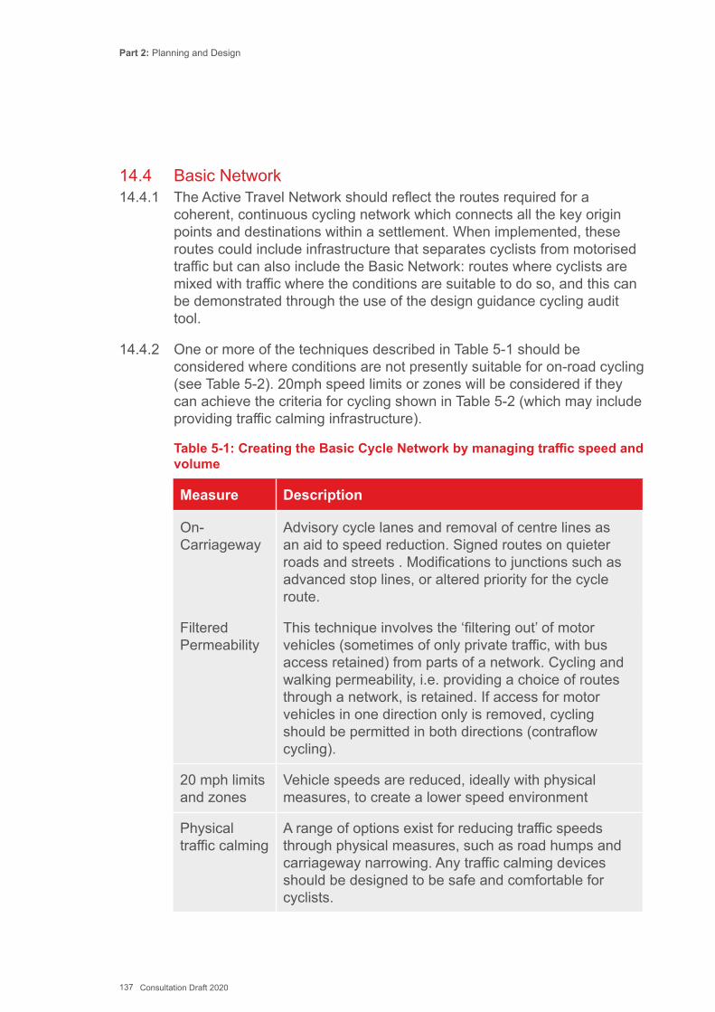
Part 2: Planning and Design
137 Consultation Draft 2020
14.4 Basic Network14.4.1 The Active Travel Network should reflect the routes required for a
coherent, continuous cycling network which connects all the key origin points and destinations within a settlement. When implemented, these routes could include infrastructure that separates cyclists from motorised traffic but can also include the Basic Network: routes where cyclists are mixed with traffic where the conditions are suitable to do so, and this can be demonstrated through the use of the design guidance cycling audit tool.
14.4.2 One or more of the techniques described in Table 5-1 should be considered where conditions are not presently suitable for on-road cycling (see Table 5-2). 20mph speed limits or zones will be considered if they can achieve the criteria for cycling shown in Table 5-2 (which may include providing traffic calming infrastructure).
Table 5-1: Creating the Basic Cycle Network by managing traffic speed and volume
Measure Description
On-Carriageway
Advisory cycle lanes and removal of centre lines as an aid to speed reduction. Signed routes on quieter roads and streets . Modifications to junctions such as advanced stop lines, or altered priority for the cycle route.
Filtered Permeability
This technique involves the ‘filtering out’ of motor vehicles (sometimes of only private traffic, with bus access retained) from parts of a network. Cycling and walking permeability, i.e. providing a choice of routes through a network, is retained. If access for motor vehicles in one direction only is removed, cycling should be permitted in both directions (contraflow cycling).
20 mph limits and zones
Vehicle speeds are reduced, ideally with physical measures, to create a lower speed environment
Physical traffic calming
A range of options exist for reducing traffic speeds through physical measures, such as road humps and carriageway narrowing. Any traffic calming devices should be designed to be safe and comfortable for cyclists.
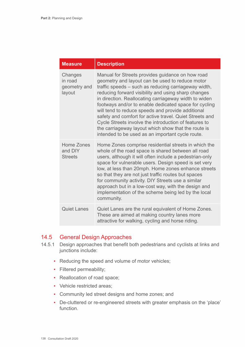
Part 2: Planning and Design
138 Consultation Draft 2020
Measure Description
Changes in road geometry and layout
Manual for Streets provides guidance on how road geometry and layout can be used to reduce motor traffic speeds – such as reducing carriageway width, reducing forward visibility and using sharp changes in direction. Reallocating carriageway width to widen footways and/or to enable dedicated space for cycling will tend to reduce speeds and provide additional safety and comfort for active travel. Quiet Streets and Cycle Streets involve the introduction of features to the carriageway layout which show that the route is intended to be used as an important cycle route.
Home Zones and DIY Streets
Home Zones comprise residential streets in which the whole of the road space is shared between all road users, although it will often include a pedestrian-only space for vulnerable users. Design speed is set very low, at less than 20mph. Home zones enhance streets so that they are not just traffic routes but spaces for community activity. DIY Streets use a similar approach but in a low-cost way, with the design and implementation of the scheme being led by the local community.
Quiet Lanes Quiet Lanes are the rural equivalent of Home Zones. These are aimed at making country lanes more attractive for walking, cycling and horse riding.
14.5 General Design Approaches14.5.1 Design approaches that benefit both pedestrians and cyclists at links and
junctions include:
▪ Reducing the speed and volume of motor vehicles; ▪ Filtered permeability; ▪ Reallocation of road space; ▪ Vehicle restricted areas; ▪ Community led street designs and home zones; and ▪ De-cluttered or re-engineered streets with greater emphasis on the ‘place’
function.
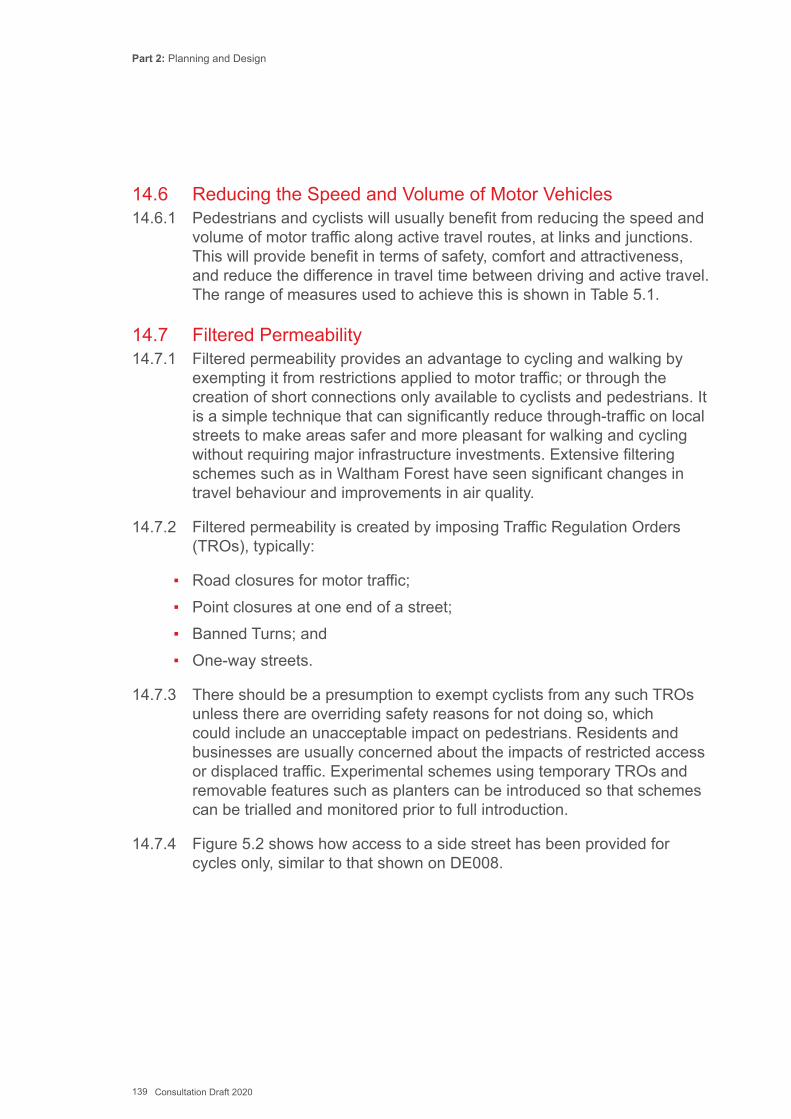
Part 2: Planning and Design
139 Consultation Draft 2020
14.6 Reducing the Speed and Volume of Motor Vehicles14.6.1 Pedestrians and cyclists will usually benefit from reducing the speed and
volume of motor traffic along active travel routes, at links and junctions. This will provide benefit in terms of safety, comfort and attractiveness, and reduce the difference in travel time between driving and active travel. The range of measures used to achieve this is shown in Table 5.1.
14.7 Filtered Permeability14.7.1 Filtered permeability provides an advantage to cycling and walking by
exempting it from restrictions applied to motor traffic; or through the creation of short connections only available to cyclists and pedestrians. It is a simple technique that can significantly reduce through-traffic on local streets to make areas safer and more pleasant for walking and cycling without requiring major infrastructure investments. Extensive filtering schemes such as in Waltham Forest have seen significant changes in travel behaviour and improvements in air quality.
14.7.2 Filtered permeability is created by imposing Traffic Regulation Orders (TROs), typically:
▪ Road closures for motor traffic; ▪ Point closures at one end of a street; ▪ Banned Turns; and ▪ One-way streets.
14.7.3 There should be a presumption to exempt cyclists from any such TROs unless there are overriding safety reasons for not doing so, which could include an unacceptable impact on pedestrians. Residents and businesses are usually concerned about the impacts of restricted access or displaced traffic. Experimental schemes using temporary TROs and removable features such as planters can be introduced so that schemes can be trialled and monitored prior to full introduction.
14.7.4 Figure 5.2 shows how access to a side street has been provided for cycles only, similar to that shown on DE008.
Part 2: Planning and Design
140 Consultation Draft 2020
Figure 5.2: Modal filter at road closure (Ealing)
14.8 Reallocation of road space14.8.1 The reallocation of road space from motor vehicles to active travel modes
not only creates better conditions for walking and cycling but also makes a statement that active travel is considered to be at least as important as motorised travel. Typically this will involve one or more of the following:
▪ Filtered permeability to create quiet streets and neighbourhoods, e.g. road closures (with exemptions for pedestrians and cyclists);
▪ Removal of one or more general traffic lanes; ▪ Reduced width of general traffic lanes; ▪ Removal of centre line; ▪ Removal or relocation of car parking; and ▪ Pedestrian-friendly streets with wider footways or informal footway areas
protected by features such as planters and bollards within a level surface.
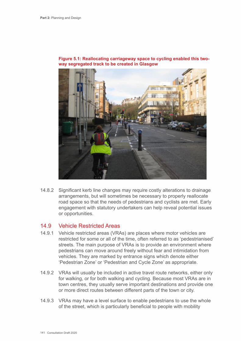
Part 2: Planning and Design
141 Consultation Draft 2020
Figure 5.1: Reallocating carriageway space to cycling enabled this two- way segregated track to be created in Glasgow
14.8.2 Significant kerb line changes may require costly alterations to drainage arrangements, but will sometimes be necessary to properly reallocate road space so that the needs of pedestrians and cyclists are met. Early engagement with statutory undertakers can help reveal potential issues or opportunities.
14.9 Vehicle Restricted Areas14.9.1 Vehicle restricted areas (VRAs) are places where motor vehicles are
restricted for some or all of the time, often referred to as ‘pedestrianised’ streets. The main purpose of VRAs is to provide an environment where pedestrians can move around freely without fear and intimidation from vehicles. They are marked by entrance signs which denote either ‘Pedestrian Zone’ or ‘Pedestrian and Cycle Zone’ as appropriate.
14.9.2 VRAs will usually be included in active travel route networks, either only for walking, or for both walking and cycling. Because most VRAs are in town centres, they usually serve important destinations and provide one or more direct routes between different parts of the town or city.
14.9.3 VRAs may have a level surface to enable pedestrians to use the whole of the street, which is particularly beneficial to people with mobility
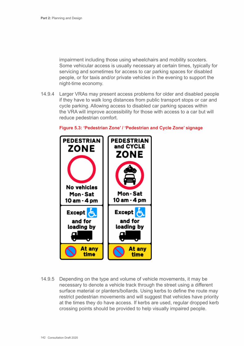
Part 2: Planning and Design
142 Consultation Draft 2020
impairment including those using wheelchairs and mobility scooters. Some vehicular access is usually necessary at certain times, typically for servicing and sometimes for access to car parking spaces for disabled people, or for taxis and/or private vehicles in the evening to support the night-time economy.
14.9.4 Larger VRAs may present access problems for older and disabled people if they have to walk long distances from public transport stops or car and cycle parking. Allowing access to disabled car parking spaces within the VRA will improve accessibility for those with access to a car but will reduce pedestrian comfort.
Figure 5.3: ‘Pedestrian Zone’ / ‘Pedestrian and Cycle Zone’ signage
14.9.5 Depending on the type and volume of vehicle movements, it may be necessary to denote a vehicle track through the street using a different surface material or planters/bollards. Using kerbs to define the route may restrict pedestrian movements and will suggest that vehicles have priority at the times they do have access. If kerbs are used, regular dropped kerb crossing points should be provided to help visually impaired people.
Part 2: Planning and Design
143 Consultation Draft 2020
14.9.6 Seating, lighting and litter bins will normally be required. Convenient cycle parking is important, particularly for cyclists with mobility impairment, who need to park close to shops and other facilities. All street furniture should be located so that it does not interfere with pedestrian desire lines and the vehicle track. Street furniture should contrast with background materials to increase its visibility.
14.9.7 Cycling in VRAs can cause concerns, particularly to people with physical, sensory and cognitive impairments who may not expect cyclists to be present, and this issue can be therefore be contentious. However, serious consideration should always be given to allowing cycling through VRAs. These areas are often prime destinations where shops and services are located and so good access is important. Alternative routes often include heavily trafficked gyratory systems or roads used by HGVs servicing shopping areas, and may pose a greater risk to cyclists. If cyclists are required to travel longer distances via more heavily trafficked routes around the VRA this will tend to suppress cycle trips and reduce cycle safety.
14.9.8 Research into the level of conflict between cyclists and pedestrians was carried out by TRL in the study ‘Cycling in Vehicle Restricted Areas (2003). This study found that cyclists alter their behaviour according to the density of pedestrian traffic – as pedestrian flows rise, the incidence of cyclists choosing to dismount also rises and those cyclists who continue to ride do so at a lower speed.
14.9.9 If cycling is prohibited within a VRA for all or part of the day the alternative routes for cyclists should offer equivalent coherence, directness, safety, comfort and attractiveness and meet the minimum design requirements for an active travel route.
14.9.10 Restrictions on cycling may only be required at certain times of day. Permitting cycling before 10 am and after 4 pm allows commuter cycling while avoiding the busiest periods of pedestrian activity. A period when no cycling is permitted is also beneficial to people who wish to be certain of a vehicle-free space for their personal safety. Cycling should not be restricted during times when motor vehicles are permitted.
14.10 Pedestrian prioritised and informal streets14.10.1 Design of these streets aims to reduce the dominance of motor
vehicles with measures to reduce their priority and enhance the status of pedestrians and cyclists. The designs usually involve significant

Part 2: Planning and Design
144 Consultation Draft 2020
improvements to the public realm such as high-quality surfaces, street trees, planting and seating. Careful design and monitoring is necessary to ensure that safety is maintained or improved.
14.10.2 A review undertaken in 2018 by IHT has identified two types of approach; Pedestrian Prioritised Streets with very low volumes of motor traffic where the whole street is primarily for pedestrians; and Informal Streets where volumes are higher and designated space for walking and cycling is required, as well as defined pedestrian crossing points. The specific issues for blind and partially sighted people are described in more detail in the National Federation of the Blind (2013) Access for Blind People in Towns.
14.10.3 A level surface is a form of shared space, where the street is not physically divided by kerbs or a level difference indicating areas for particular modes. These streets need careful design if they are to work for all users.
14.10.4 Blind and partially sighted people find shared space difficult to use and may avoid such areas due to fear of road danger and difficulty in navigating through the space. Obviously, such issues apply mainly within town centres and high streets that blind people visit rather than within lightly trafficked residential access streets.
14.10.5 Guidance paving can help to provide a distinct, detectable route for blind and partially sighted pedestrians to follow along the sides of a shared space and does not prevent other pedestrians from sharing the central part of the space. Currently the only confirmed demarcation fully detectable to most blind people and recognized by guide dogs is a footway raised above the carriageway with at least 60mm kerb upstand. Colour, texture and tonal contrast between the carriageway and the footway areas will also help.
14.11 Link Design Considerations14.11.1 A link is defined as a section of route between junctions. Of the five basic
requirements set out in Chapters 12 and 13 the three most important for links are:
▪ Direct; ▪ Safe; and ▪ Comfortable.
Part 2: Planning and Design
145 Consultation Draft 2020
Direct14.11.2 Pedestrians and cyclists prefer to follow natural desire lines which avoid
deviations. Where pedestrian routes are indirect many users will take the shortest available desire line, away from the formal footway or footpath. Routes for cyclists should be as least as direct as those for motor traffic.
14.11.3 Directness in terms of time is important. Having to slow down or stop imposes a substantial time penalty and wasted effort. Cycle tracks should be of adequate width for the expected flows to enable overtaking amongst cyclists.
Safe14.11.4 The risk of injury to pedestrians and cyclists should be minimised. On
links, attention should be given to:
▪ Providing sufficient width for pedestrians so that they are not required to step into the paths of motor vehicles or cyclists due to crowding;
▪ Ensuring adequate geometry, visibility and space for cyclists to avoid running into the path of motor traffic or pedestrians, allowing for errors and evasive manoeuvres;
▪ Minimising conflict between cyclists and pedestrians by providing separation between them, allowing sharing to take place only where there is sufficient width for the number of users.
▪ Physically separating cyclists from motorised traffic; ▪ Avoiding conflicts between cyclists and oncoming traffic (including other
cyclists); and ▪ Ensuring that the design of any infrastructure for cyclists reflects how
cyclists are trained through National Standards Cycle Training.
Comfortable14.11.5 Walking and cycling infrastructure should minimise discomfort by:
▪ Minimising the gradients and keeping slopes as short as possible (see Chapter 12)
▪ Providing smooth, well-maintained surfaces (see Chapter 18); ▪ Avoiding placing obstructions in a route and removing existing ones; ▪ Providing adequate width for the volume of pedestrian and cycle traffic; ▪ Minimising effort by avoiding cyclists having to slow down or stop on
links;

Part 2: Planning and Design
146 Consultation Draft 2020
▪ Minimising nuisance from motor traffic, through reduced speeds and greater separation; and
▪ Minimising conflict between pedestrians and cyclists.
Attractive14.11.6 Pedestrians and cyclists are much more exposed to their environment
than people in motor vehicles, so more sensitive to the quality of experience when using a route. Routes should:
▪ Look attractive and be interesting; ▪ Integrate with and complement their surroundings; ▪ Contribute to good urban design; ▪ Feel secure, be well overlooked and lit; and ▪ Be well maintained.
14.12 Segregation between Cyclists and Pedestrians DE023, DE024, DE032 and DE03314.12.1 Cyclists using off-carriageway tracks, through green spaces and
on highways at links and junctions, will usually need to interact with pedestrians. The two possible approaches to the design of routes where pedestrians and cyclists are using the same route are:
▪ Cyclists and pedestrians each have their own defined segregated space; and
▪ Unsegregated provision, where cyclists and pedestrians share the space.
14.12.2 Early consultation with relevant interested parties, such as those representing disabled people, walkers and cyclists, should form part of design development process to inform design decisions.
14.12.3 Separate provision for cycling is preferred as this will enable blind people to use footways with more confidence and enable cyclists to maintain their desired speed. This is important on active travel routes, which are designed for everyday use as a realistic alternative to the car over short distances.
14.12.4 For a segregated path to operate effectively, there must be adequate width for each user group, and the means of separation should be effective. Non-compliance with segregation will result in increased potential for conflict amongst all users. If levels of non-compliance are anticipated to be high due to inadequate space for effective segregation, options include:

Part 2: Planning and Design
147 Consultation Draft 2020
▪ Increasing the path width; ▪ Providing an unsegregated track; and ▪ Providing an alternative route for cycling.
14.12.5 When deciding whether a route should be segregated or not, one should consider:
▪ Pedestrian and cycle flow (both the volume and any conflicting directions of movement);
▪ Cycle speed; ▪ Cycle journey purpose; ▪ Visibility; ▪ Whether significant numbers of vulnerable users are expected - elderly,
disabled, children; ▪ Available width and any pinch points e.g. bridges; and ▪ Exchange’ activity - shopping, playing etc.
14.12.6 Advantages of effective segregation are:
▪ Cyclists can maintain a consistent and comfortable speed; ▪ Cyclists less likely to encounter pedestrians engaged on ‘exchange’
activities - e.g. playing, shopping; ▪ More comfortable for pedestrians who may not expect the presence of
cyclists; ▪ Less intimidation for vulnerable pedestrians, particularly the visually
impaired; ▪ Reduced perception of conflict by both groups; and ▪ Keeps cyclists away from driveways as the cycle track is usually located
next to the carriageway.
14.12.7 Disadvantages of segregation include:
▪ Territorial behaviour by users may increase conflict. ▪ Pedestrians walking in groups (especially at weekends and school
journeys) are likely to ignore segregation unless widths are adequate ▪ More expensive to construct and require more land; and ▪ May be more visually intriusive in sensitive areas.
Part 2: Planning and Design
148 Consultation Draft 2020
14.12.8 Advantages of unsegregated routes:
▪ More flexible use - for example, cyclists may be the majority group during the weekday peak, and pedestrians in groups during weekends;
▪ Routes with a wide single surface are better able to accommodate larger cycles, such as those used by disabled people, and people in wheelchairs;
▪ •Routes may be cheaper to construct and maintain due to less complex engineering and a narrower overall width. (Construction costs can be up to three times higher if segregation by kerb is used);
▪ Routes may require fewer signs and markings, thereby reducing visual intrusion and maintenance costs; and
▪ Can be a useful way of accommodating many different movement types especially at crossings, bus stops and complex junctions.
14.12.9 Disadvantages of unsegregated routes include:
▪ Potentially intimidating for pedestrians, particularly visually impaired people, and especially with high volumes of cyclists;
▪ Can be frustrating for cyclists who have to limit their speed to accommodate pedestrians; and
▪ Normal ‘rules of the road’ such as keep left are not observed so it can be hard to predict others behaviour during interactions.
14.13 Type of segregation14.13.1 Segregation should normally incorporate design features such as
contrasting materials, a change in levels or a grass verge (see Figure 5.4). Materials that give a good tonal contrast will help all users to differentiate the cycle and pedestrian paths, and are valuable for visually impaired pedestrians. Usually this will involve using asphalt for cyclists and light coloured paviours for pedestrians.
14.13.2 Segregation using simple white lines (Diag 1049) (which are not detectable by blind users) or a raised white line delineator (Diag 1049.1) is rarely respected by pedestrians, unless cycle flows are high or there is generous width, and should not normally be used.
14.14 Monitoring and Management14.14.1 Where cyclists are routed alongside or with pedestrians, it is advisable to
monitor the scheme performance. Where practicable, engagement with local people (or representative organisations) who may no longer use the path because of its design. This will enable any concerns to be identified early on and suitable mitigating measures implemented if required (see also Chapter 20).
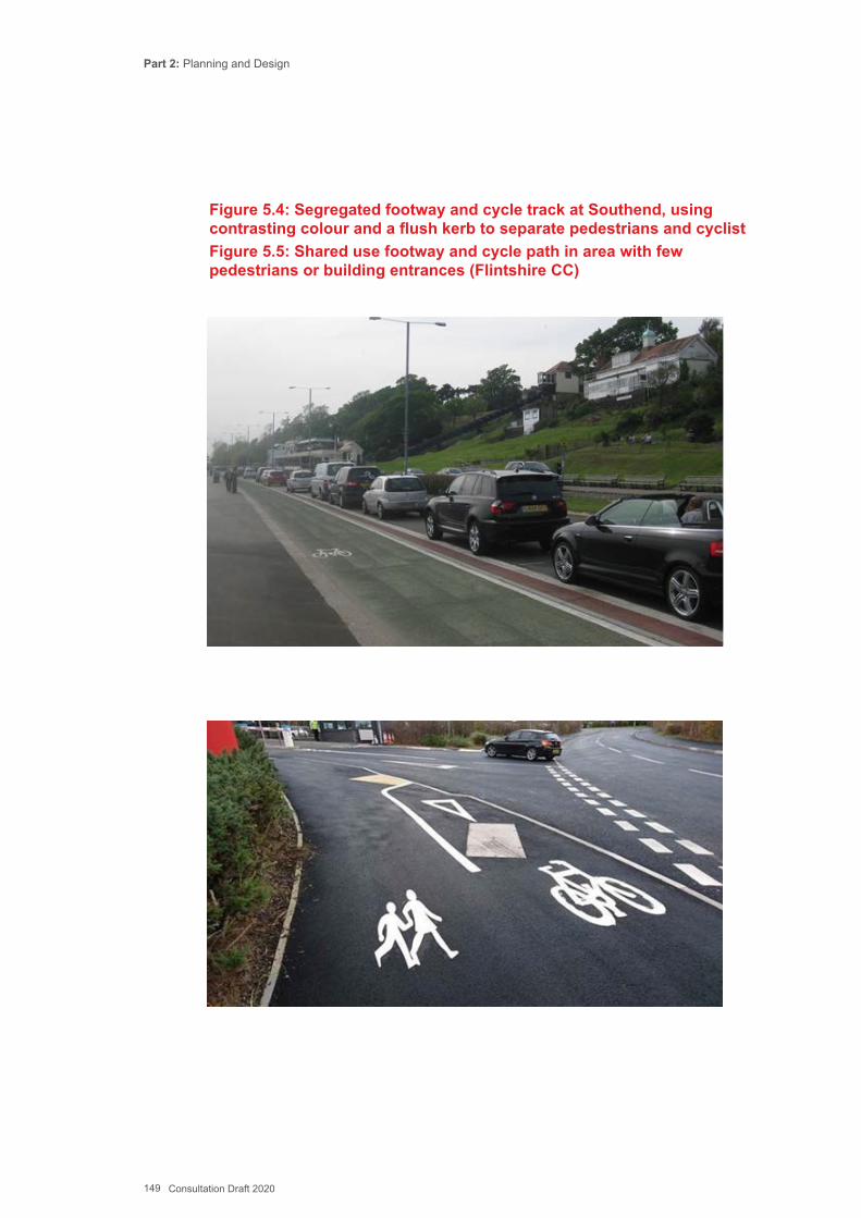
Part 2: Planning and Design
149 Consultation Draft 2020
Figure 5.4: Segregated footway and cycle track at Southend, using contrasting colour and a flush kerb to separate pedestrians and cyclistFigure 5.5: Shared use footway and cycle path in area with few pedestrians or building entrances (Flintshire CC)
Part 2: Planning and Design
150 Consultation Draft 2020
14.15 Pedestrians on Links – DE001, DE002, DE003 and DE00414.15.1 Pedestrian routes are usually on footways adjacent to carriageways.
Other walking routes will include footpaths away from roads, such as paths through housing estates, parks and alongside waterways (DE002) and other elements of the rights of way network such as bridleways. Where footways or footpaths are being designed as a shared use path for pedestrians and cyclists (segregated or unsegregated) refer to 5.11 and DEs 023, 024, 032 and 033.
14.15.2 Walking routes should follow direct desire lines as closely as possible, be of sufficient width for the level of use, and gradients should be accessible to all users.
Widths14.15.3 The required width of a footway or footpath will depend on the pedestrian
flows and whether a verge is needed due to the speed or composition of vehicles if there is an adjacent carriageway.
14.15.4 Basic minimum widths are given in Chapter 12 and summarised in DE001 and DE002. Where pedestrian flows are very high, a detailed assessment of pedestrian capacity and comfort should be made (see TfL Pedestrian Comfort Guidelines, summarised in Chapter 12). If there are high levels of static pedestrian activity such as photography near tourist attractions, additional space will be needed.
14.15.5 If a footway is adjacent to a road with high vehicle speeds or a high proportion of HGVs a margin may be needed to separate the footway from the road, or to provide additional footway width. Footway widths may be increased by reallocating carriageway space, and removing or rationalising street clutter. Removing unnecessary street furniture and locating remaining furniture in an area out of the main pedestrian flow helps remove hazards for visually impaired people and can improve the street appearance.
14.15.6 Litter bins and other potential obstructions should have a minimum height of 1.0m and be continuous to the ground rather than sited on posts. DE1 provides guidance on the need for hazard protection to isolated objects.
14.15.7 Footway parking is not generally prohibited in Wales, but local authorities can do so with a Traffic Regulation Order. Physical measures, such as bollards, raised planters or other street furniture along the edge of the footway can prevent unlawful access, while positive provision of marked parking bays can encourage compliance.
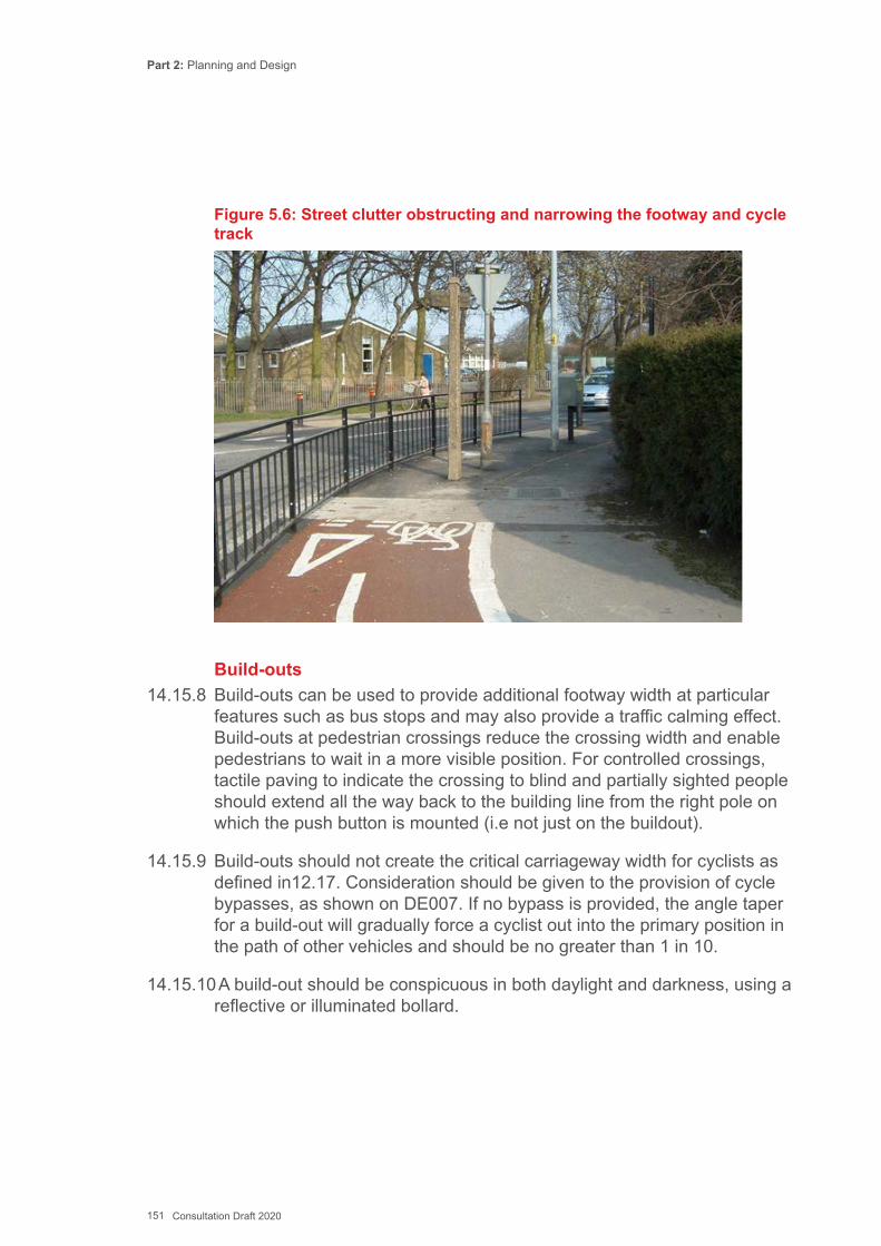
Part 2: Planning and Design
151 Consultation Draft 2020
Figure 5.6: Street clutter obstructing and narrowing the footway and cycle track
Build-outs14.15.8 Build-outs can be used to provide additional footway width at particular
features such as bus stops and may also provide a traffic calming effect. Build-outs at pedestrian crossings reduce the crossing width and enable pedestrians to wait in a more visible position. For controlled crossings, tactile paving to indicate the crossing to blind and partially sighted people should extend all the way back to the building line from the right pole on which the push button is mounted (i.e not just on the buildout).
14.15.9 Build-outs should not create the critical carriageway width for cyclists as defined in12.17. Consideration should be given to the provision of cycle bypasses, as shown on DE007. If no bypass is provided, the angle taper for a build-out will gradually force a cyclist out into the primary position in the path of other vehicles and should be no greater than 1 in 10.
14.15.10 A build-out should be conspicuous in both daylight and darkness, using a reflective or illuminated bollard.
Part 2: Planning and Design
152 Consultation Draft 2020
14.16 Gradients, Ramps and Steps14.16.1 The longitudinal profile of a footway adjacent to a carriageway should
generally follow its vertical alignment, although there may be situations where a footway can usefully be maintained on a steady vertical profile while the carriageway goes through a sharp dip or crest. In these situations, a retaining wall or slope between the carriageway and the footway will be necessary.
14.16.2 The gradients of footways and footpaths should accord where with the guidance given in Chapter 12, summarised on DE001 and DE002.
14.16.3 Ramps and steps to facilitate a sharp change in level or grade should not be used on a walking route unless it cannot be avoided. The design of ramps and steps is shown in DE003 and DE004.
14.16.4 Steps should normally be provided in conjunction with a ramp to provide accessibility for mobility impaired pedestrians. Steps can offer a useful shortcut to maintain desire lines to accommodate a change in level or grade. Steps should have clearly visible nosings/edges, handrails to both sides, and corduroy warning paving to the top and bottom. Visual contrast between elements will help highlight features such as edges and handrails.
14.16.5 Existing steps on active travel routes should be assessed against DE004, with improvements made if necessary. Wheeling ramps for cycles are covered in 14.51.
14.17 Cycling on Links - Introduction14.17.1 Table 5.2 shows how existing levels of motor traffic volume and speed
offer a starting point to designers. Considering these factors may lead to the decision to separate cyclists from motor traffic, or to restrain traffic speeds and volumes to a level where inexperienced and child cyclists feel comfortable using the carriageway. Streets that already have low motor traffic speeds and volumes help to make up the basic network.
14.17.2 An equally important factor is the place/movement context. Areas with a high place value should not introduce additional ‘clutter’ to accommodate segregated cycling, but should aim to reduce traffic speeds and volumes where possible. By contrast inter-urban links with few frontages and side roads will typically need to accommodate high flows and speeds of traffic, with the resulting need for greater separation for cyclists.
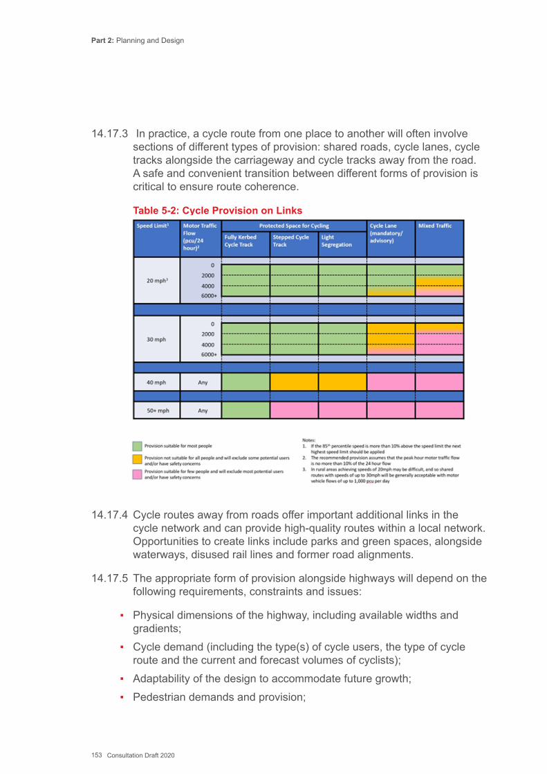
Part 2: Planning and Design
153 Consultation Draft 2020
14.17.3 In practice, a cycle route from one place to another will often involve sections of different types of provision: shared roads, cycle lanes, cycle tracks alongside the carriageway and cycle tracks away from the road. A safe and convenient transition between different forms of provision is critical to ensure route coherence.
Table 5-2: Cycle Provision on Links
14.17.4 Cycle routes away from roads offer important additional links in the cycle network and can provide high-quality routes within a local network. Opportunities to create links include parks and green spaces, alongside waterways, disused rail lines and former road alignments.
14.17.5 The appropriate form of provision alongside highways will depend on the following requirements, constraints and issues:
▪ Physical dimensions of the highway, including available widths and gradients;
▪ Cycle demand (including the type(s) of cycle users, the type of cycle route and the current and forecast volumes of cyclists);
▪ Adaptability of the design to accommodate future growth; ▪ Pedestrian demands and provision;

Part 2: Planning and Design
154 Consultation Draft 2020
▪ Motor traffic speeds; ▪ Motor traffic volumes, including the volume of HGVs; ▪ Interface with adjoining sections of route; ▪ The type and arrangement of junctions, including the frequency of minor
arm junctions, intervisibility with conflicting traffic, and the potential to provide cycle priority;
▪ Conflicting uses, such as bus stops, loading and parking; and ▪ Place functions and visual character – what is the aesthetic context.
14.17.6 The preference is usually to look at reducing carriageway space before considering taking space away from pedestrians to create cycle tracks or shared use paths, unless the existing path is much wider than required for the volume of users.
14.17.7 Separation from motor traffic may be done by:
▪ Separation in time – using traffic signals to separate cyclists and motor traffic movements;
▪ Light segregation - Intermittent physical separation from motor vehicles (e.g. use of refuges, planters, bollards, or other features);
▪ Continuous physical separation that can be crossed by cyclists (e.g. low kerb); and
▪ Continuous physical separation that can only be crossed at designated locations (e.g. full height kerb, verge).
14.18 Traffic Lane Widths and Car Parking14.18.1 Designers will need to consider the widths of general traffic lanes and
parking spaces when designing active travel routes and reallocating space. Designers will need to assess the minimum width requirements of moving and stationary vehicles, and when cyclists are sharing the carriageway, how the lane widths relate to the recommended riding positions.
Lane Widths14.18.2 Figure 5.7 is taken from Manual for Streets and provides an indication of
what traffic combinations various carriageway widths can accommodate. Figure 5.9 is taken from the Cardiff Cycling Design Guide and provides guidance on the size of vehicles that traffic lane widths can accommodate. Widths pertaining to trunk roads are given in TD27, although it should be noted that TD50 permits lane widths as narrow
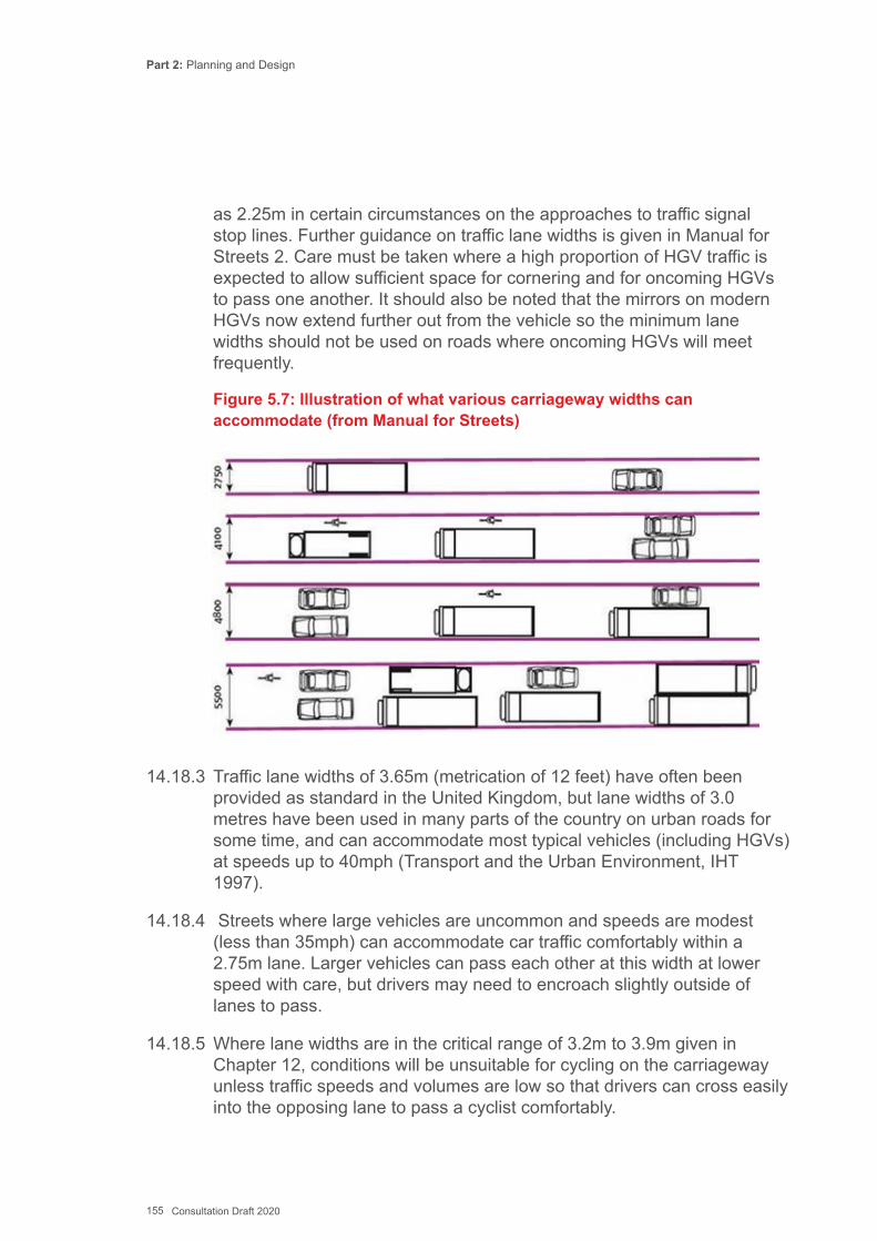
Part 2: Planning and Design
155 Consultation Draft 2020
as 2.25m in certain circumstances on the approaches to traffic signal stop lines. Further guidance on traffic lane widths is given in Manual for Streets 2. Care must be taken where a high proportion of HGV traffic is expected to allow sufficient space for cornering and for oncoming HGVs to pass one another. It should also be noted that the mirrors on modern HGVs now extend further out from the vehicle so the minimum lane widths should not be used on roads where oncoming HGVs will meet frequently.
Figure 5.7: Illustration of what various carriageway widths can accommodate (from Manual for Streets)
14.18.3 Traffic lane widths of 3.65m (metrication of 12 feet) have often been provided as standard in the United Kingdom, but lane widths of 3.0 metres have been used in many parts of the country on urban roads for some time, and can accommodate most typical vehicles (including HGVs) at speeds up to 40mph (Transport and the Urban Environment, IHT 1997).
14.18.4 Streets where large vehicles are uncommon and speeds are modest (less than 35mph) can accommodate car traffic comfortably within a 2.75m lane. Larger vehicles can pass each other at this width at lower speed with care, but drivers may need to encroach slightly outside of lanes to pass.
14.18.5 Where lane widths are in the critical range of 3.2m to 3.9m given in Chapter 12, conditions will be unsuitable for cycling on the carriageway unless traffic speeds and volumes are low so that drivers can cross easily into the opposing lane to pass a cyclist comfortably.

Part 2: Planning and Design
156 Consultation Draft 2020
Figure 5.8 - Vehicles and Lane Widths (from Cardiff Cycling Design Guide)
Car Parking Width14.18.6 Parked vehicles ideally require a standard width of 2.4m for a parking
space but in practice this is often difficult to accommodate in existing streets. 2.0m is the preferred minimum – this still provides a margin of error for poorly parked vehicles. Widths between 1.8m and 2.0m are only recommended if space constraints require such narrow widths.
14.18.7 Cyclists are taught to ride well clear of parked cars to avoid collisions with opening car doors, and cycle lanes should be separated from car parking by a buffer zone (at least 0.5m) for that reason – see DE015 below.
14.19 Cycling in All-Purpose Traffic Lanes14.19.1 Table 5.2 gives indicative conditions where motor traffic volumes and
speeds are sufficiently low to enable cyclists to share a carriageway with other traffic.
14.19.2 It is important to consider whether design modifications could help reinforce the speed limit or address potential conflict sites such as pinch points, and not simply to assume that cyclists can use the existing layout.
14.20 Reducing Traffic Volumes and Speeds DE005, DE006, DE00714.20.1 Where traffic volumes and speeds exceed the values for a shared
carriageway (Table 6.2) consideration should be given reducing traffic flows and speeds so that cycling can be accommodated on the carriageway. Table 5-1 provides a list of suitable techniques - guidance on filtered permeability is given in section 5.7
Part 2: Planning and Design
157 Consultation Draft 2020
14.21 Contraflow Cycling DE009 and DE01014.21.1 One-way streets and gyratory systems for traffic management are
commonplace. One-way streets can significantly reduce the density of the cycling network, which becomes less cohesive, less direct, less comfortable, less safe and less attractive. Some cyclists may then elect to travel illegally against the flow of traffic, or do this on the footway.
14.21.2 The permeability for cyclists can be greatly enhanced by exempting them from one-way restrictions, and encourages active travel with connections unavailable to drivers. Retaining two-way cycling should be considered if it is proposed to introduce one-way working for general traffic. The operation of existing one-way streets should be reviewed with a view to permitting two-way cycling wherever safe and practicable. The design should consider the possible impact on pedestrians and whether they can anticipate that cyclists will be travelling in both directions or whether additional signs are needed at crossing locations.
14.22 Traffic Calming DE005, DE006 and DE00714.22.1 Traffic calming measures can reduce motor vehicle speeds thereby
improving safety for pedestrians and cyclists and improving conditions for residents living along traffic calmed routes. Whether and how to implement traffic calming must take particular account of feedback from the emergency services and bus operators.
14.22.2 Traffic calming can improve cycling conditions by reducing motor traffic speeds, but poorly designed vertical features can be uncomfortable for cyclists and horizontal deflections and pinch points can feel hazardous.
14.22.3 Sinusoidal humps are more comfortable for cyclists – see DE006 for details. Cycle bypasses should ideally be provided at pinch points – see DE007.
14.22.4 Changes in basic road geometry and appearance, such as using narrower carriageways, removing centre line markings, reducing forward visibility, sharp changes in direction or changes in priority at junctions can all contribute to speed reduction.

Part 2: Planning and Design
158 Consultation Draft 2020
Figure 5.9: Contraflow cycling in a narrow street with no marked lane –Brighton
Figure 5.10: Relationship between carriageway widths, forward visibility and speed, from Manual for Streets
Part 2: Planning and Design
159 Consultation Draft 2020
14.23 Quiet Streets DE01114.23.1 Quiet Streets are urban cycling routes on low traffic speed and volume
back streets, which are generally suitable for new and less confident cyclists. This may include filtered permeability and other measiures to remove traffic. Routes should maintain continuity for cycling and tackle barriers such as junctions and crossings at main roads that provide access to otherwise quiet streets.
14.23.2 Cycle symbols to Diagram 1057 can be used to sign cycle routes and indicate the correct positioning for cycling within the carriageway.
14.24 Cycle Streets DE01214.24.1 A Cycle Street is a Quiet Street which also serves as a Primary Cycle
Route. To succeed it should carry low volumes of motor traffic, and high volumes of cycling that significantly exceed motor traffic levels, to provide cyclists with a level of comfort comparable to that provided by a traffic free route.
14.24.2 The objectives of a Cycle Street are to:
▪ Present a legible design recognisable to all types of user as a main cycle route;
▪ Influence behaviour so that cyclists assume priority with drivers of motor vehicles behaving as ‘guests’, travelling at low speeds;
▪ Maintain priority for cyclists, so that drivers do not overtake them until they leave the cycle street; and
▪ Be attractive to experienced cyclists and less confident cyclists.14.24.3 Cycle streets are not recognized within TSRGD or the Traffic Signs
Manual. The Department for Transport previously indicated that Cycle Streets could be subject to:
▪ A ban on motor vehicles overtaking cyclists; and ▪ An advisory speed limit of 15mph.
14.24.4 Signs and orders to support these restrictions would therefore require special authorisation from Welsh Ministers and authorities should seek advice from Welsh Government.
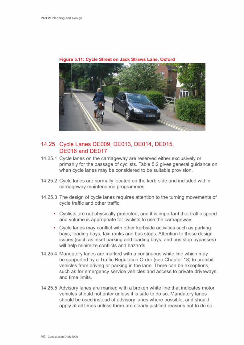
Part 2: Planning and Design
160 Consultation Draft 2020
Figure 5.11: Cycle Street on Jack Straws Lane, Oxford
14.25 Cycle Lanes DE009, DE013, DE014, DE015, DE016 and DE01714.25.1 Cycle lanes on the carriageway are reserved either exclusively or
primarily for the passage of cyclists. Table 5.2 gives general guidance on when cycle lanes may be considered to be suitable provision.
14.25.2 Cycle lanes are normally located on the kerb-side and included within carriageway maintenance programmes.
14.25.3 The design of cycle lanes requires attention to the turning movements of cycle traffic and other traffic;
▪ Cyclists are not physically protected, and it is important that traffic speed and volume is appropriate for cyclists to use the carriageway;
▪ Cycle lanes may conflict with other kerbside activities such as parking bays, loading bays, taxi ranks and bus stops. Attention to these design issues (such as inset parking and loading bays, and bus stop bypasses) will help minimize conflicts and hazards.
14.25.4 Mandatory lanes are marked with a continuous white line which may be supported by a Traffic Regulation Order (see Chapter 18) to prohibit vehicles from driving or parking in the lane. There can be exceptions, such as for emergency service vehicles and access to private driveways, and time limits.
14.25.5 Advisory lanes are marked with a broken white line that indicates motor vehicles should not enter unless it is safe to do so. Mandatory lanes should be used instead of advisory lanes where possible, and should apply at all times unless there are clearly justified reasons not to do so.
Part 2: Planning and Design
161 Consultation Draft 2020
14.25.6 Raised thermoplastic markings can be used to help deter incursion by motor vehicles.
14.25.7 Whilst such cycle lanes have historically been regarded as an integral part of active travel networks, and will still be acceptable in certain circumstances, due to the limited protection which they offer cyclists local authorities are encouraged to consider the inclusion of light segregation features in the design of new schemes (see 4.21) to offer greater physical protection to cyclists, in line with the design principles set out in Section 12.2.
14.26 Car parking / loading and Cycle Lanes DE01514.26.1 Kerbside vehicle parking or loading can often be dangerous for cyclists
especially in a street with high vehicle turnover rates as there is a high risk of vehicle doors being opened into the path of cyclists within the cycle lane. It is therefore necessary that any cycle lane must pass parking areas with a sufficient dividing strip (buffer zone) or else be of sufficient width to enable cyclists to travel in the cycle lane away from the parking. Inset bays or build-outs may help protect space for cyclists.
14.27 Cycle Lanes at Side Roads DE01614.27.1 Cycle lanes across side road junctions ensure continuity and help
improve cycle safety. Continuous mandatory cycle lanes across side road junctions are not permitted. A road marking to diagram 1010 can be used to mark the lane at the junction mouth (1m line, 1m gap) as in TSRGD 2016. A cycle symbol to diagram 1057 may also be placed within the lane at the junction mouth.
14.27.2 Increasing the cycle lane width at side roads can help encourage cyclists to position themselves further from the kerb to avoid vehicles nosing into the main road, or turning left across the cyclist. Side road entry treatments help reduce the speeds of vehicles turning in and out of the junction.
14.28 Removal of centre lines DE01714.28.1 The removal of centre lines is useful where carriageway widths would not
otherwise permit the introduction of cycle lanes, and as a speed reduction measure.
14.28.2 Where on-coming motor vehicles have to pass each other, both vehicles momentarily pulling over into their respective near-side advisory cycle lanes, having first checked to see they are clear of cyclists. For this

Part 2: Planning and Design
162 Consultation Draft 2020
reason a maximum two-way flow of around 4500 motor vehicles a day, or 500 per hour at peak times is recommended. With more traffic there is higher risk of conflict with cyclists.
Figure 5.12: Centreline removed to allow advisory cycle lanes to be introduced, Cathays Terrace, Cardiff
14.29 Cycle lanes with light segregation DE018, DE019, DE02014.29.1 A mandatory cycle lane along the side of a road may be reinforced
by “light segregation” from the main carriageway, using a variety of intermittent low-level physical features such as planters, wands (retroreflective collapsible bollards), and other features usually constructed from PVC or recycled rubber. The intermittent obstacles enable cyclists to pass between the cycle track and the carriageway as necessary, to turn right for example. Existing drainage can still be used so the installation cost is minimal compared to conventional kerbed facilities. Successful schemes are operating in Salford, Manchester, Bristol, Newcastle and London as well as around the globe.
14.29.2 The features are not road markings and therefore no authorisation is needed from Welsh Ministers. They are bounded by the solid white line of a mandatory cycle lane, and should be marked with a broken white line at junctions. A vertical feature such as a bollard or wand should be used at the beginning and end of each run to ensure they are visible to road users and to help avoid damage to the separators.

Part 2: Planning and Design
163 Consultation Draft 2020
Figure 5.13: Light Segregated Cycle Lane, Royal College Street, Camden (Note: lane marking should be on outside of raised features)
Figure 5.14: Light segregated cycle track with wand at start, Salford, Greater Manchester (Note – only one lane marking, outside the raised features, should be used).
14.30 Stepped Cycle Tracks DE021 and DE02214.30.1 Stepped cycle tracks have a cycle facility raised slightly above the
carriageway surface but sitting below the level of the footway. This type of solution is common in Copenhagen, and it has been used in Brighton,
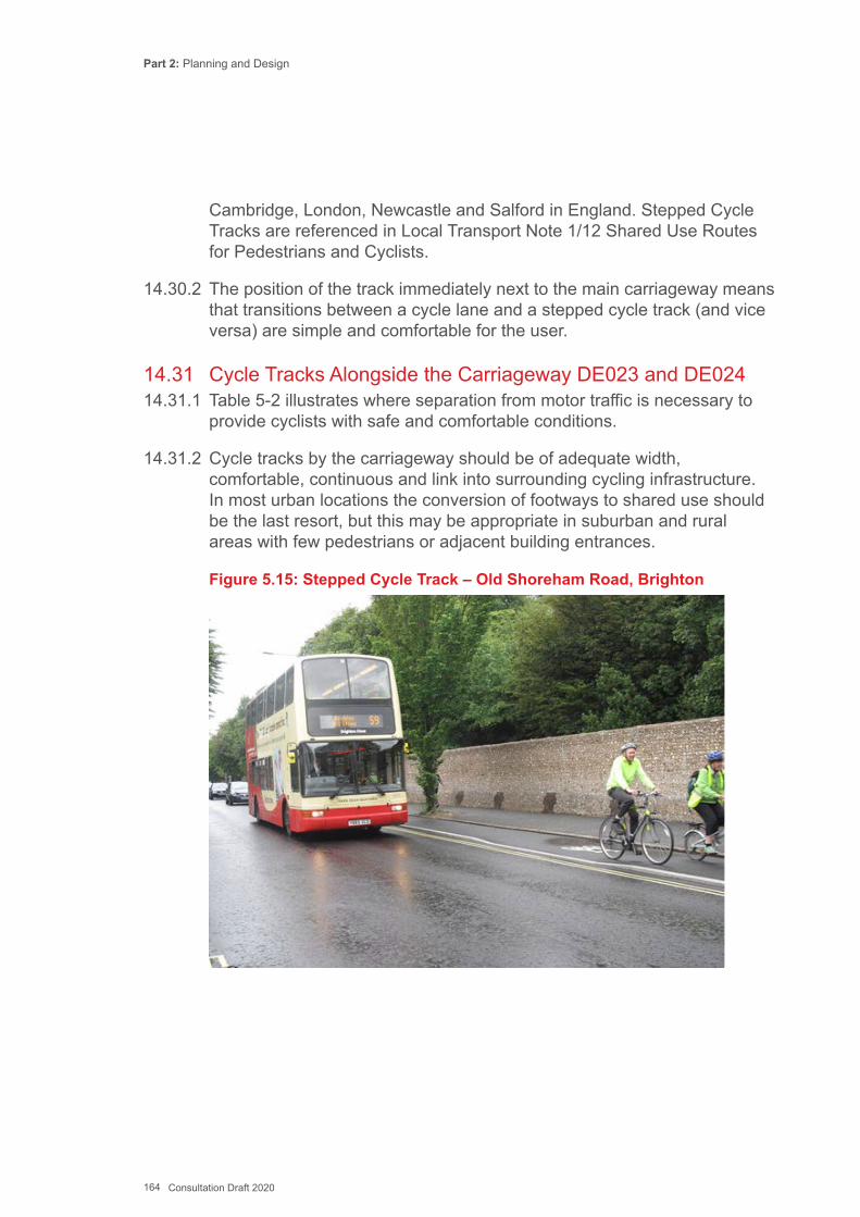
Part 2: Planning and Design
164 Consultation Draft 2020
Cambridge, London, Newcastle and Salford in England. Stepped Cycle Tracks are referenced in Local Transport Note 1/12 Shared Use Routes for Pedestrians and Cyclists.
14.30.2 The position of the track immediately next to the main carriageway means that transitions between a cycle lane and a stepped cycle track (and vice versa) are simple and comfortable for the user.
14.31 Cycle Tracks Alongside the Carriageway DE023 and DE02414.31.1 Table 5-2 illustrates where separation from motor traffic is necessary to
provide cyclists with safe and comfortable conditions.
14.31.2 Cycle tracks by the carriageway should be of adequate width, comfortable, continuous and link into surrounding cycling infrastructure. In most urban locations the conversion of footways to shared use should be the last resort, but this may be appropriate in suburban and rural areas with few pedestrians or adjacent building entrances.
Figure 5.15: Stepped Cycle Track – Old Shoreham Road, Brighton
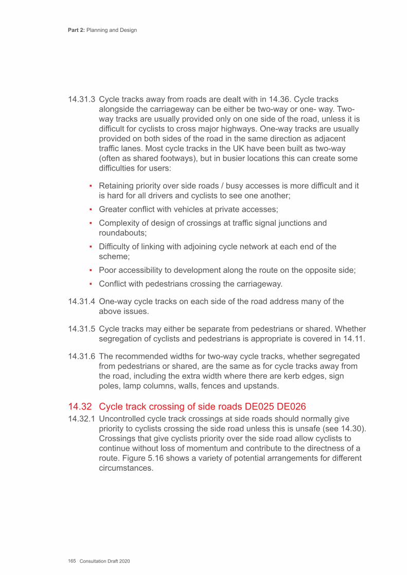
Part 2: Planning and Design
165 Consultation Draft 2020
14.31.3 Cycle tracks away from roads are dealt with in 14.36. Cycle tracks alongside the carriageway can be either be two-way or one- way. Two- way tracks are usually provided only on one side of the road, unless it is difficult for cyclists to cross major highways. One-way tracks are usually provided on both sides of the road in the same direction as adjacent traffic lanes. Most cycle tracks in the UK have been built as two-way (often as shared footways), but in busier locations this can create some difficulties for users:
▪ Retaining priority over side roads / busy accesses is more difficult and it is hard for all drivers and cyclists to see one another;
▪ Greater conflict with vehicles at private accesses; ▪ Complexity of design of crossings at traffic signal junctions and
roundabouts; ▪ Difficulty of linking with adjoining cycle network at each end of the
scheme; ▪ Poor accessibility to development along the route on the opposite side; ▪ Conflict with pedestrians crossing the carriageway.
14.31.4 One-way cycle tracks on each side of the road address many of the above issues.
14.31.5 Cycle tracks may either be separate from pedestrians or shared. Whether segregation of cyclists and pedestrians is appropriate is covered in 14.11.
14.31.6 The recommended widths for two-way cycle tracks, whether segregated from pedestrians or shared, are the same as for cycle tracks away from the road, including the extra width where there are kerb edges, sign poles, lamp columns, walls, fences and upstands.
14.32 Cycle track crossing of side roads DE025 DE02614.32.1 Uncontrolled cycle track crossings at side roads should normally give
priority to cyclists crossing the side road unless this is unsafe (see 14.30). Crossings that give cyclists priority over the side road allow cyclists to continue without loss of momentum and contribute to the directness of a route. Figure 5.16 shows a variety of potential arrangements for different circumstances.
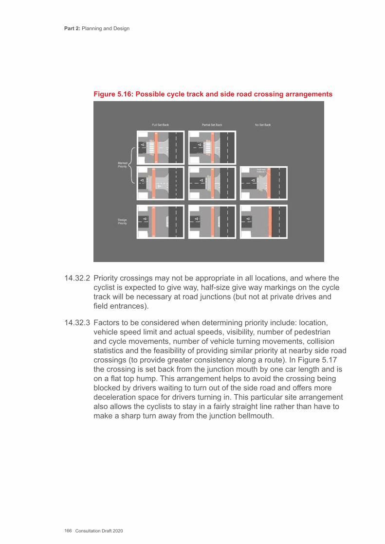
Part 2: Planning and Design
166 Consultation Draft 2020
Figure 5.16: Possible cycle track and side road crossing arrangements
14.32.2 Priority crossings may not be appropriate in all locations, and where the cyclist is expected to give way, half-size give way markings on the cycle track will be necessary at road junctions (but not at private drives and field entrances).
14.32.3 Factors to be considered when determining priority include: location, vehicle speed limit and actual speeds, visibility, number of pedestrian and cycle movements, number of vehicle turning movements, collision statistics and the feasibility of providing similar priority at nearby side road crossings (to provide greater consistency along a route). In Figure 5.17 the crossing is set back from the junction mouth by one car length and is on a flat top hump. This arrangement helps to avoid the crossing being blocked by drivers waiting to turn out of the side road and offers more deceleration space for drivers turning in. This particular site arrangement also allows the cyclists to stay in a fairly straight line rather than have to make a sharp turn away from the junction bellmouth.
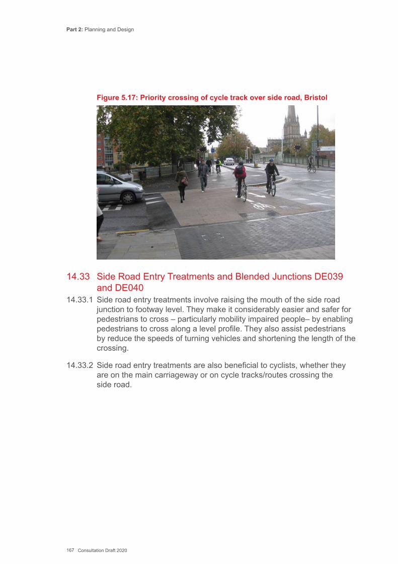
Part 2: Planning and Design
167 Consultation Draft 2020
Figure 5.17: Priority crossing of cycle track over side road, Bristol
14.33 Side Road Entry Treatments and Blended Junctions DE039 and DE04014.33.1 Side road entry treatments involve raising the mouth of the side road
junction to footway level. They make it considerably easier and safer for pedestrians to cross – particularly mobility impaired people– by enabling pedestrians to cross along a level profile. They also assist pedestrians by reduce the speeds of turning vehicles and shortening the length of the crossing.
14.33.2 Side road entry treatments are also beneficial to cyclists, whether they are on the main carriageway or on cycle tracks/routes crossing the side road.
Part 2: Planning and Design
168 Consultation Draft 2020
Figure 5.18: Semi blended footway at side road with kerb line and tactiles retained, Clapham
14.33.3 A variant on this is the ‘blended’ junction, where there is no change in the footway material, no flush kerbs and no tactile paving, where vehicles are effectively crossing a widened footway. Choice of locations for this design should take account of the needs of older pedestrians and disabled people.
14.34 Cycle tracks in centre of carriageway DE02714.34.1 An option which has been little used in the UK yet is to place two-way
cycle tracks in the centre of single carriageway streets, or one way tracks alongside central reservations. This can provide a good facility for cycling along busy highways without encountering obstructions such as bus stops and driveways. Access to and from the central track is critical, and is typically achieved via controlled crossings and at signalized junctions. It will be necessary to ban turns across the central track at side roads, if it is not possible to create a suitable junction. Regular pedestrian crossing facilities will also be necessary.
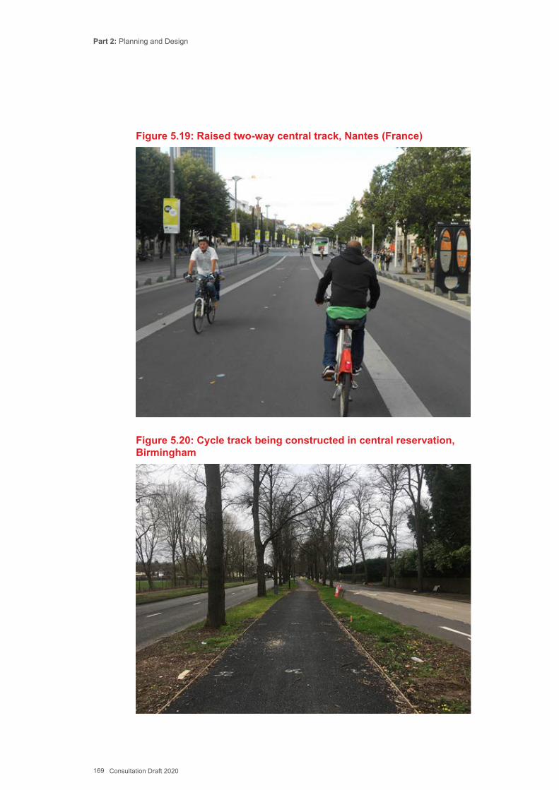
Part 2: Planning and Design
169 Consultation Draft 2020
Figure 5.19: Raised two-way central track, Nantes (France)
Figure 5.20: Cycle track being constructed in central reservation, Birmingham

Part 2: Planning and Design
170 Consultation Draft 2020
14.35 Cycle Lanes/Tracks at Bus Stops DE028 DE029 DE030 DE03114.35.1 People using cycle lanes and cycle tracks adjacent to the carriageway
will either pass a bus on the off-side, with potential conflict with buses and passing traffic, or on the footway side, with potential obstructions by street furniture and conflict with waiting / alighting pedestrians at the bus stop.
Figure 5.21: Simple bus-boarder arrangement in rural location. Bus stop pole at back of footway to keep space clear.
14.35.2 No standard layout for cycle lanes / tracks at bus stops can address all considerations but there is a wide range of possible layouts. Each site will need considering on its own merits taking the following points into consideration:
▪ Ensuring there is available space for cyclists to pass a stationary bus (either in the carriageway or to the footway side of the bus stop) so that momentum is maintained;
▪ Making it clear that cyclists must adjust their behaviour and speed to avoid conflict with pedestrians around bus stops;
▪ Adequate space for pedestrians to wait for the bus where they do not pose an obstruction to any cycle bypass;
▪ Sufficient safe space within a bus stop island for a wheelchair and helper to alight and turn;
▪ Good intervisibility between pedestrians (those waiting for a bus as well as those passing) and cyclists, to minimise potential for conflict;
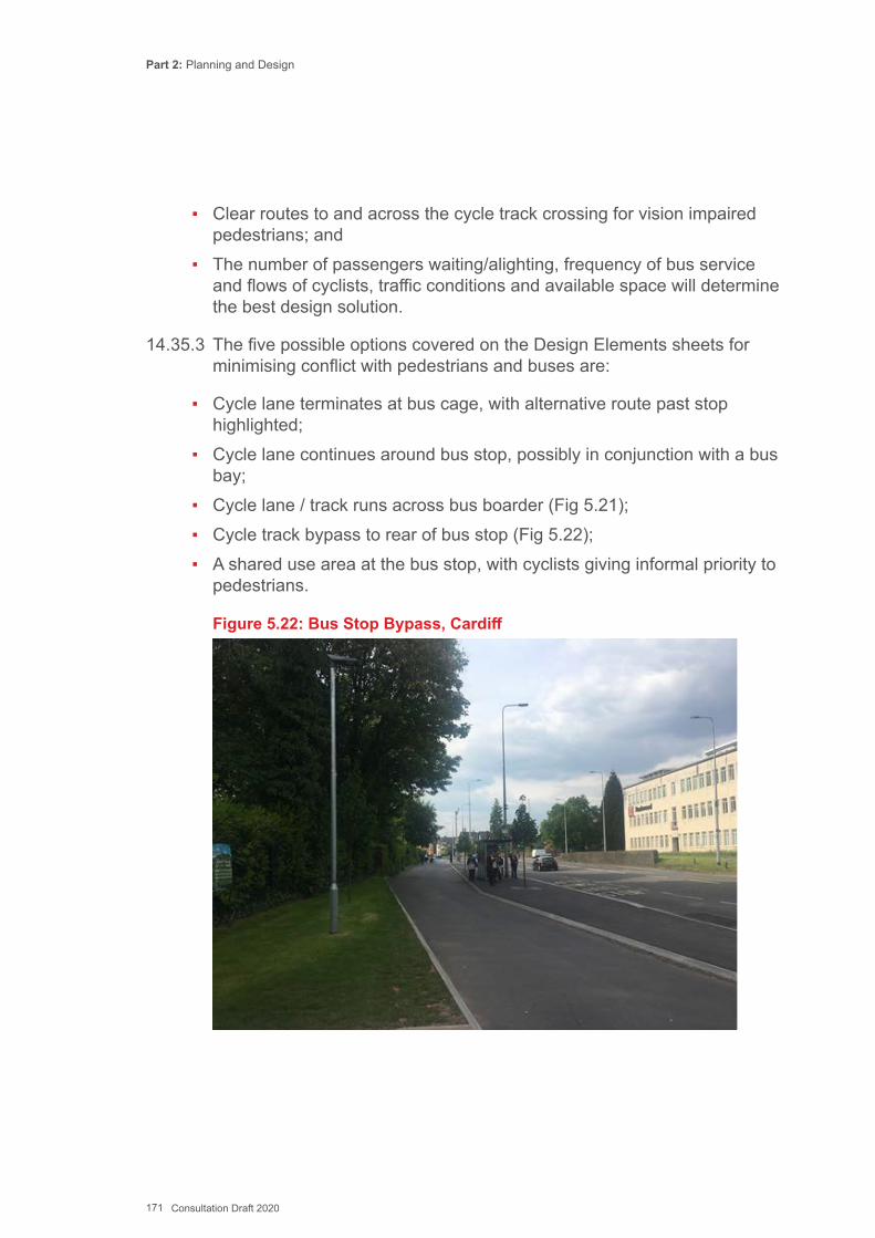
Part 2: Planning and Design
171 Consultation Draft 2020
▪ Clear routes to and across the cycle track crossing for vision impaired pedestrians; and
▪ The number of passengers waiting/alighting, frequency of bus service and flows of cyclists, traffic conditions and available space will determine the best design solution.
14.35.3 The five possible options covered on the Design Elements sheets for minimising conflict with pedestrians and buses are:
▪ Cycle lane terminates at bus cage, with alternative route past stop highlighted;
▪ Cycle lane continues around bus stop, possibly in conjunction with a bus bay;
▪ Cycle lane / track runs across bus boarder (Fig 5.21); ▪ Cycle track bypass to rear of bus stop (Fig 5.22); ▪ A shared use area at the bus stop, with cyclists giving informal priority to
pedestrians.
Figure 5.22: Bus Stop Bypass, Cardiff
Part 2: Planning and Design
172 Consultation Draft 2020
14.36 Cycle Tracks away from Roads DE032 and DE03314.36.1 Routes away from motorised traffic are referred to as traffic-free routes
or Greenways. They can be developed in urban, urban fringe and rural areas in a wide range of linear corridors. Routes that provide direct connections between journey attractors with good connectivity to other parts of the network will achieve high usage.
14.36.2 Guidance on techniques for separation of cyclists and pedestrians is given in 14.11 above.
Potential Corridors for Traffic Free Routes14.36.3 The most common types of corridors used as traffic free routes are:
▪ Urban parks; ▪ Urban corridors; ▪ Disused railway alignments; ▪ Seaside promenades; ▪ Canal and riverside tracks; ▪ River and coastal flood banks; ▪ Footpaths and bridleways; ▪ Amenity spaces such as golf course, racecourses, stately homes; ▪ Abandoned road alignments; and ▪ Through open space provided by new developments.
14.36.4 Each corridor will present its own, sometimes unique, set of challenges that will need to be overcome.
14.36.5 Key elements of successful traffic-free routes include:
▪ Routes should be direct and follow desire lines wherever possible, avoiding steep gradients;
▪ Route capacity and widths should be adequate for peak forecast demand conditions;
▪ Mminimum visibility and corner radii should be provided, based on the appropriate design speed;
▪ Good quality surface materials should be used.

Part 2: Planning and Design
173 Consultation Draft 2020
14.36.6 Restrictive access controls, vegetation growth that encroaches on the track surface, poor or inadequate lighting, poor sightlines or poorly maintained track surfaces will deter users.
14.36.7 Equestrians should not be denied access to routes that they currently have the right to use by changing the classification of the rights of way. There needs to be clear signing of which routes are intended for use by equestrians. If widths permit, a separate unsealed surface may be preferable for equestrians.
14.37 Design and Construction of Routes away from the Highway14.37.1 The design and construction process should consider:
Design ▪ The connections between the corridor and the wider network; ▪ The types, journey purpose and future volumes of users; ▪ The available track width and any constraints; ▪ The horizontal track alignment and any visibility constraints; and ▪ Gradients and accessibility.
Construction ▪ Formation and sub-base; ▪ Surface dressings suitable for utility cycling; ▪ Edges and verge treatments; ▪ Drainage; ▪ Lighting; and ▪ Ancillary works.
Track Widths14.37.2 The track width should be able to comfortably accommodate the current,
forecast and any target increase in users, including from planned land-use development. A width greater than the minimum will increase the level of service, permit sociable (side by side) cycling and walking, and accommodate future growth in active travel.
14.37.3 Cycle tracks should include additional width where they are bounded by vertical features because it is only practical to use the whole track width to cycle where there is open space alongside.
Part 2: Planning and Design
174 Consultation Draft 2020
Junctions Between Traffic Free Routes14.37.4 Cycles cannot turn right angles, and pedestrians will usually cut a corner,
so providing a radius that enables cycling speed to be maintained, and accommodates the track of larger cycles will also help prevent erosion of ‘desire lines’ in adjacent grassed areas. Blind and partially sighted pedestrians use the path edges and turns to aid navigation so additional guidance may be needed to help them at junctions. Junctions between cycle tracks should normally have a minimum 2.0m curve radius or 45º chamfer.
Speed Control Measures14.37.5 Excessive speed by cyclists can be an issue on downhill gradients and
on bends where constraints prevent minimum stopping sight distances being provided. Warning signs may have some effect but may need to be complemented by physical measures.
14.37.6 Away from the carriageway, speed control may be integrated into public art using sculptures or landforms to create horizontal and vertical features. Speed control options include:
▪ Speed humps; ▪ Bollards, including staggered layouts; ▪ Chicane-type deviations; ▪ Rumble strips; and ▪ Signs/markings.
14.37.7 The design considerations for speed control measures on cycle tracks include:
▪ Accessibility » Accessibility must be maintained for all legitimate users, including all
types of cycle, pedestrians and wheelchair/mobility scooters; » A restriction in track width will slow down users as they negotiate it but
also introduces a different type of potential conflict point where users have to give way to one another; and
» Barriers often cause access problems for people with disabilities and should generally be introduced as a last resort.
▪ Siting of speed control measures » Careful consideration should be given to the location and distance
between speed control measures so that they do not impede progress or create additional conflicts between users.
Part 2: Planning and Design
175 Consultation Draft 2020
▪ Visibility » The feature may present a hazard to users and should be clearly
visible in daylight and darkness. ▪ Maintenance vehicle access
» Does the track require vehicular access for maintenance? » Can any locking mechanisms be suitably managed and maintained?
▪ Prevention of bypassing » Bypassing must be prevented or at least not be easier than passing
through the speed control measure. ▪ Speed humps
» Speed humps profiles must be constructed to acceptable tolerance. DE006 provides details of the preferred sinusoidal hump profile;
» Precast concrete products are available but may be prohibitively expensive, and without a flat base they can also rock and create a trip hazard;
» Speed humps on slopes should not increase the gradient of the hump beyond the absolute maximum 1 in 12.
14.38 Cycling on Rural Roads14.38.1 Most cycling takes place in urban areas, but roads outside built-up areas
provide key links for cyclists who live in rural areas making journeys to local destinations or nearby urban areas.
14.38.2 Cycling on rural roads can feel hazardous due to higher traffic speeds, restricted visibility and narrow carriageways. Measures to reduce motor traffic speeds and volumes may be implemented to help reduce the risks to cyclists and pedestrians.
14.38.3 On-carriageway active travel cycle routes in rural areas should generally follow roads with low traffic flows, preferably below 1,000 vehicles AADT and with actual traffic speeds no greater than 30mph. The design of cycle routes should be sympathetic to the local environment with limited use of intrusive signing and road markings.
14.38.4 The rural active travel experience can be improved with design features that aim to make rural roads safer and more pleasant places to travel by foot and cycle.
Part 2: Planning and Design
176 Consultation Draft 2020
Gated Closures/Restrictions14.38.5 Closing or restricting access to motor traffic on minor roads is an effective
way of improving conditions for walkers and cyclists. Simple measures can be introduced, such as a mode-filter with a cycle gap, or direction signs leading through traffic away from minor roads used by the active travel routes. Local engagement and consultation on TROs will be required.
Changed Priorities - Junction Redesign14.38.6 Where two minor roads intersect (i.e. with two-way traffic flows less
than 1,000vpd on each arm), the road with the major cycle flow can be given priority. This can often be achieved simply by relocating give-way markings and signs, but it may be necessary to undertake works to improve or maintain the visibility splays.
Reduced speed limits14.38.7 Most of the rural road network is subject to the national speed limit of
60mph. The geometry of many rural roads is inadequate for this speed, and where an active travel route is being promoted, reduced speed limits should be considered.
14.38.8 Speed limit reductions alone are unlikely to substantially reduce average speeds without additional physical measures, especially at approaches to isolated hazards, junctions and bends.
Traffic in Villages
It is important that access in and around villages is suitable for active travel modes. Traffic in Villages is a publication produced by Dorset AONB Partnership which provides a toolkit that can be used for successful village design.
The mechanisms in the above publication for creating successful villages will also coincide in helping achieve better cycling conditions and facilities. These include reducing speed limits, creating gateways, improving crossing points, wayfinding measures, public spaces/meeting points, de- cluttering, etc. It is important that these principles do not inadvertently make worse cycle conditions by taking into consideration:
Designing out existing and avoid creating pinch points (e.g. at gateways)
Cycle access maintained at closures or restrictions
Part 2: Planning and Design
177 Consultation Draft 2020
Uncomfortable surface materials (e.g. cobbles)
Retaining and improving upon cycle signing
Car parking (ensuring echelon and other forms of parking do not create dangerous conditions for cyclists)
Cycle parking
Centre line removal14.38.9 Centre lines can increase traffic speeds since they help guide motorists
and give them greater confidence to negotiate oncoming traffic. Removing centrelines on lightly trafficked roads can typically help reduce average speeds by up to 3mph, and may form part of an overall strategy to reduce traffic danger.
14.38.10 The introduction of motor traffic restrictions (e.g. signed HGV alternative routes, and/or weight & width restrictions) can help reduce traffic volume to create suitable conditions for centre line removal.
Gateway Treatment14.38.11 Gateways (usually a vertical sign or gate on each side of the road) are
used at a village boundary to raise driver awareness of an approaching settlement where drivers are expected to reduce speed. Lower speed limits and physical traffic calming are often used to help enforce this measure.
14.38.12 Gateways can sometimes form pinch points for cyclists, especially hazardous if traffic speeds are still above 30mph. Where pinch points are intentionally created, cycle bypasses should be provided see DE007.
14.38.13 Gateways do not have to take the form of a pinch point as they can be subtly created by using planting, different road colours/materials and other visual changes that mark the contrast between high speed roads and low speed villages. The removal of centre line markings within the built-up area after the gateway can help highlight a change in road character to a lower-speed environment.
14.39 Transitions between Cycle Tracks and the Carriageway DE03414.39.1 The transition for cyclists between a cycle track (including a shared use
path) and the carriageway should be safe and comfortable. Where the transition is on a link, cyclists should be able to continue along their direction of travel without bumping up and down kerbs, without having to turn sideways to look behind them and without giving way to vehicles
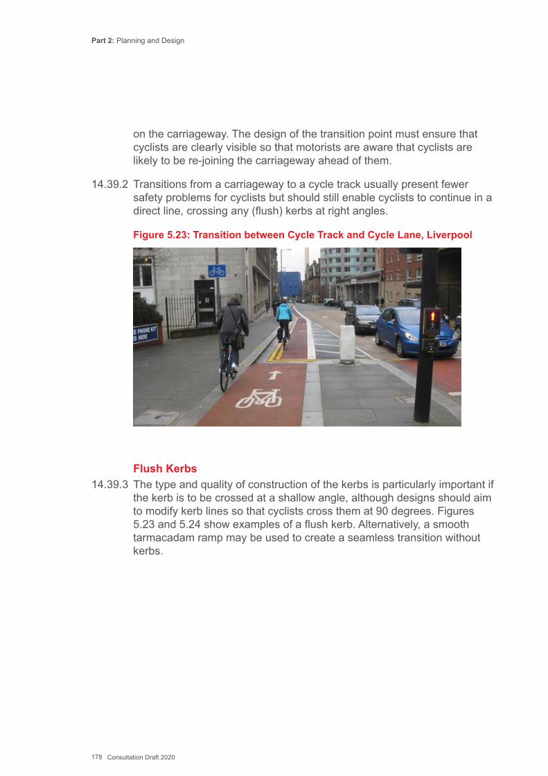
Part 2: Planning and Design
178 Consultation Draft 2020
on the carriageway. The design of the transition point must ensure that cyclists are clearly visible so that motorists are aware that cyclists are likely to be re-joining the carriageway ahead of them.
14.39.2 Transitions from a carriageway to a cycle track usually present fewer safety problems for cyclists but should still enable cyclists to continue in a direct line, crossing any (flush) kerbs at right angles.
Figure 5.23: Transition between Cycle Track and Cycle Lane, Liverpool
Flush Kerbs14.39.3 The type and quality of construction of the kerbs is particularly important if
the kerb is to be crossed at a shallow angle, although designs should aim to modify kerb lines so that cyclists cross them at 90 degrees. Figures 5.23 and 5.24 show examples of a flush kerb. Alternatively, a smooth tarmacadam ramp may be used to create a seamless transition without kerbs.
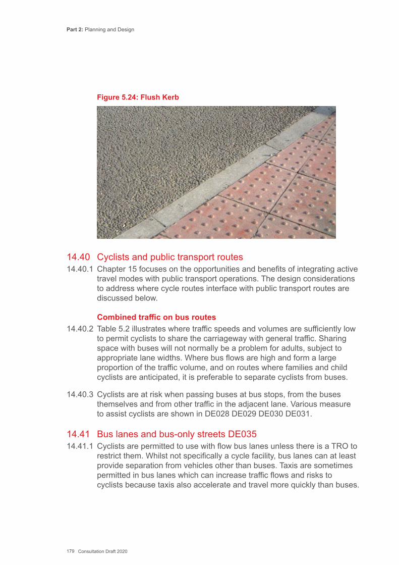
Part 2: Planning and Design
179 Consultation Draft 2020
Figure 5.24: Flush Kerb
14.40 Cyclists and public transport routes14.40.1 Chapter 15 focuses on the opportunities and benefits of integrating active
travel modes with public transport operations. The design considerations to address where cycle routes interface with public transport routes are discussed below.
Combined traffic on bus routes14.40.2 Table 5.2 illustrates where traffic speeds and volumes are sufficiently low
to permit cyclists to share the carriageway with general traffic. Sharing space with buses will not normally be a problem for adults, subject to appropriate lane widths. Where bus flows are high and form a large proportion of the traffic volume, and on routes where families and child cyclists are anticipated, it is preferable to separate cyclists from buses.
14.40.3 Cyclists are at risk when passing buses at bus stops, from the buses themselves and from other traffic in the adjacent lane. Various measure to assist cyclists are shown in DE028 DE029 DE030 DE031.
14.41 Bus lanes and bus-only streets DE03514.41.1 Cyclists are permitted to use with flow bus lanes unless there is a TRO to
restrict them. Whilst not specifically a cycle facility, bus lanes can at least provide separation from vehicles other than buses. Taxis are sometimes permitted in bus lanes which can increase traffic flows and risks to cyclists because taxis also accelerate and travel more quickly than buses.
Part 2: Planning and Design
180 Consultation Draft 2020
14.41.2 In order to be considered suitable to be an designated active travel route, the bus lane should still meet the criteria given in Table 5.2 – i.e. a separate cycle lane (and potentially a light segregated track) will be needed in some circumstances for the route to be considered suitable for inclusion on the existing route map.
14.41.3 Where bus lanes are provided, care should be taken to ensure that provision for cyclists in the opposite direction is not compromised.
14.41.4 Contraflow bus lanes should be of sufficient width to accommodate cyclists. The widths referred to in DE035 for with-flow bus lanes apply. However, for short stretches, or where flows are low, narrower lanes may be acceptable, which will mean that buses will not be able to pass cyclists.
14.41.5 Where bus-only links are provided, for example between two residential neighbourhoods, the design should normally include provision for cyclists as well (either within the busway or adjacent to it).
14.42 Cycling and Trams14.43.1 Only one mile of operational tramway currently operates in Wales. It is
important to ensure that any potential future tramway schemes do not compromise the needs of cyclists. There are also a few situations where narrow-guage railway lines cross or travel along the carriageway.
14.42.2 Cyclists and trams can share the same carriageway but this requires extra care during the design phase, principally to make sure cyclists do not cross the rails at too shallow an angle (on links and at junctions); typically the approach angle should be at least 45 degrees, preferably 60 degrees. Rails embedded in the carriageway contribute indirectly to hazards including:
▪ Cyclists may be concentrating on avoiding the rails and fail to notice other hazards;
▪ Cyclists are not always able to choose a safe path; and ▪ Rails restrict the scope for evasive manoeuvres to avoid other traffic
danger.
14.42.3 A mix of tram, car and cycle in the carriageway is not appropriate for active travel routes unless there is really no feasible alternative alignment.
Part 2: Planning and Design
181 Consultation Draft 2020
14.43 Crossing and Junction Design – General Principles14.43.1 The design of junctions and crossings must be comprehensible to all
users, including pedestrians and cyclists as well as motorised road users. The user requirements of directness, safety and comfort are significant at junctions and crossings.
Directness14.43.2 Directness is important for pedestrians and cyclists. The design of
junctions and crossings should consider directness in terms of both distance and crossing time. However, there is also a trade-off in that separating pedestrian and cyclist movements from other traffic for safety reasons may introduce additional delay to all users.
14.43.3 The delay experienced in negotiating a junction or crossing can considerably increase journey time for pedestrians and cyclists, both real and perceived. Reducing delay may require amending the timings of traffic-controlled junctions and crossings which may in turn affect junction capacities. If this is so a balance will need to be struck between overall junction capacity and pedestrian and cyclist delay. Where possible pedestrian and cycle routes should have priority over motorised traffic and designs should avoid arrangements that require frequent stopping and starting.
14.43.4 Pedestrians and cyclists appreciate routes through junctions that follow natural desire lines to minimise the effort required. Where routes are indirect, many users may choose a shorter route away from the formal crossing points. At side road junctions, deviations from the desire line can be minimised with the use of small corner radii. This also has the benefit of helping reduce vehicle speeds.
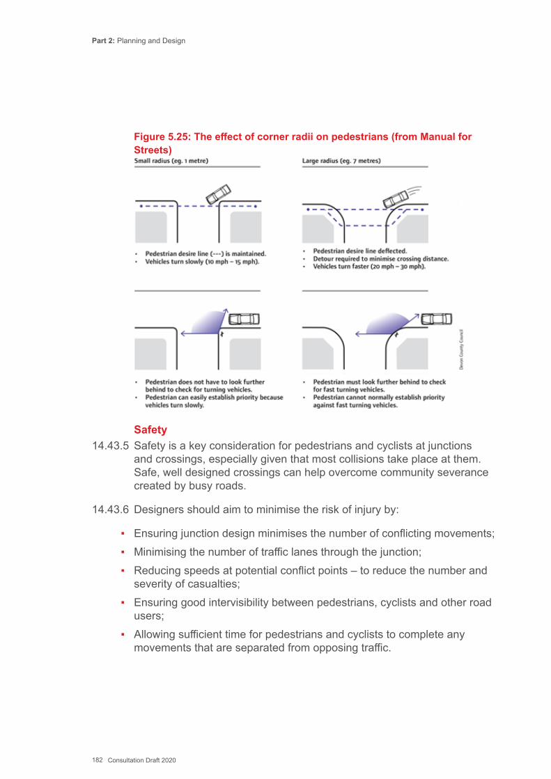
Part 2: Planning and Design
182 Consultation Draft 2020
Figure 5.25: The effect of corner radii on pedestrians (from Manual for Streets)
Safety14.43.5 Safety is a key consideration for pedestrians and cyclists at junctions
and crossings, especially given that most collisions take place at them. Safe, well designed crossings can help overcome community severance created by busy roads.
14.43.6 Designers should aim to minimise the risk of injury by:
▪ Ensuring junction design minimises the number of conflicting movements; ▪ Minimising the number of traffic lanes through the junction; ▪ Reducing speeds at potential conflict points – to reduce the number and
severity of casualties; ▪ Ensuring good intervisibility between pedestrians, cyclists and other road
users; ▪ Allowing sufficient time for pedestrians and cyclists to complete any
movements that are separated from opposing traffic.
Part 2: Planning and Design
183 Consultation Draft 2020
Comfort14.43.17 Junction layouts should accommodate pedestrians and cyclists by:
▪ Ensuring a smooth surface with flush dropped kerbs and appropriate tactile paving;
▪ Careful location of street furniture away from desire lines; ▪ Providing sufficient space for pedestrians and cyclists waiting to cross; ▪ Minimising the need to stop and start at side roads and mid-block
crossings including the provision of suitable geometry and visibility splays.
14.44 Considerations for Pedestrian and Cycle Crossings 14.44.1 The ability to cross the road safely has a major impact on people’s ability
to undertake active travel journeys. Pedestrian and cycle crossings should be provided where an active travel route crosses a major road or other barrier, and positioned as close to the desire line as possible. Crossings may be placed at junctions or mid-block. At signalled junctions, the active travel crossings are usually incorporated into the traffic signals.
14.44.2 Along a shopping street, pedestrians may want to cross at any point along a length of road, but the controlled crossings are often some distance apart. Consideration should be given to providing informal crossings at more regular intervals.
14.44.3 At all types of crossing, delays to pedestrians and cyclists on active travel routes should be minimized using measures such as offering priority, keeping cycle times as short as possible, providing maximum green times and setting standalone signals to respond immediately when the push button is pressed.
14.44.4 Cycle crossings are sometimes provided in the form of junctions, but where one or more arms of the junction are only used by cycle traffic.
14.44.5 Table 5-3 is indicative of the appropriate treatments for a stand-alone cycle crossing of a two-way carriageway. It is a guide only, and individual locations should be assessed on a case by case basis. Reducing the speed or volume of traffic using the carriageway will enable a wider range of options for the crossing design to be considered.
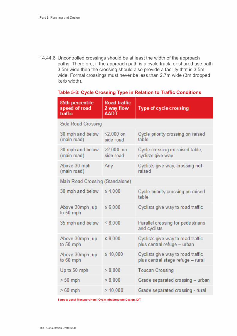
Part 2: Planning and Design
184 Consultation Draft 2020
14.44.6 Uncontrolled crossings should be at least the width of the approach paths. Therefore, if the approach path is a cycle track, or shared use path 3.5m wide then the crossing should also provide a facility that is 3.5m wide. Formal crossings must never be less than 2.7m wide (3m dropped kerb width).
Table 5-3: Cycle Crossing Type in Relation to Traffic Conditions
Source: Local Transport Note: Cycle Infrastructure Design, DfT
Part 2: Planning and Design
185 Consultation Draft 2020
14.45 Crossing Types14.45.1 The two options for crossing roads are at-grade crossings such as zebra
crossings or traffic signals; and grade-separation, such as bridges and subways.
14.45.2 At-grade crossings are more commonplace and relatively low cost. They are preferable when a grade separated crossing would cause significant deviation away from desire lines and/or raise personal safety concerns. However, grade separated crossings are a good solution if they provide a high-quality route over or under a road or other barrier. Grade separation is usually the safest solution for crossing busy roads with speed limits of 50mph and above. Grade separated crossings are discussed later in this chapter.
14.45.3 The two main types of at-grade crossing are:
▪ Uncontrolled crossings where pedestrians and cyclists wait for a gap in traffic: –
» Buff tactiles, pedestrian refuges; and ▪ Controlled crossings where other traffic has to give-way to or stop for
pedestrians and cyclists. » Unsignalised – Zebra, Parallel (zebra/cycle) » Signalised – Puffin, Ped-X, Toucan, Pegasus and signalized junctions
14.45.4 The assessment of the need for, and the type of, pedestrian or cycle crossing to be provided should be undertaken in accordance with Department for Transport and Welsh Government publication LTN 1/95 ‘The Assessment of Pedestrian Crossings’ (expected to be superseded by the latest Traffic Signs Manual Chapter 6: Traffic Control, in 2019).
14.45.5 The design of pedestrian / cycle crossings should be undertaken in accordance with Department for Transport and Welsh Government publication LTN 2/95 ‘The Design of Pedestrian Crossings’ (expected to be superseded by Traffic Signs Manual Chapter 6: Traffic Control, in 2019).
14.45.6 Where there was no previous provision, suppressed demand may mean that crossing flows are higher than anticipated, especially in residential areas.
14.45.7 This guidance does not cover Pegasus crossings (for horse riders) or Pelican crossings, which have been replaced by Puffin crossings.
Part 2: Planning and Design
186 Consultation Draft 2020
14.45.8 It is necessary to consult with the police and give public notice of the proposal to implement a new standalone controlled crossing.
14.45.9 The signing and marking arrangement for controlled crossings is prescribed in TSRGD. The regulations require the installation of a minimum of two zig-zag markings on the approach to and exit from the crossing, to prohibit vehicles waiting or overtaking on the immediate approach to the crossing.
14.45.10 The zig zag markings can be placed up to 2.0m from the kerbline, so that the zig zag markings can effectively form a continuation of the protected cycle lane, light segregation or stepped track on the approach to a crossing.
14.45.11 Crossings of all types may be highlighted with the provision of kerb build- outs, which reduce the width of a crossing, and/or by placing the crossing on a raised table. Both measures are likely to be successful in reducing vehicle speeds in the vicinity of the crossing, but care should be taken to ensure build-outs do not result in a pinch point for cyclists using the road – see DE007.
14.45.12 High friction surfacing on the approaches to a controlled crossing helps to ensure adequate skid resistance for braking vehicles. The length of high friction surfacing should be determined based on the vehicle approach speeds. The surfacing should continue past the stop or give-way line for at least one metre to cater for a vehicle overrunning the stop or give-way line.
14.45.13 Crossings should be wide enough to cater for current demand, and projected increases in use. Catering for higher numbers at the design stage will avoid a route becoming compromised because dimensions were set at the minimum required. Once installed, it can be difficult to justify further expense if a crossing needs widening.
14.46 Uncontrolled Crossings DE036 DE037, DE038, DE039 and DE04014.46.1 The simplest form of uncontrolled or informal crossing involves the
provision of dropped or flush kerbs and tactile paving to enable people to cross to and from the carriageway. Visually impaired people generally prefer signal-controlled crossings as they cannot easily tell whether other traffic is approaching or how quickly.
Part 2: Planning and Design
187 Consultation Draft 2020
14.46.2 The types of uncontrolled crossing include:
▪ Mid link crossing; ▪ Crossing of side road junctions; and ▪ Informal crossing with a central median.
14.46.3 Care should be taken over the siting of informal pedestrian crossing points in relation to vehicle crossovers so as not to cause confusion for visually impaired people. Parking restrictions may be needed around the crossing area to ensure visibility is adequate.
14.46.4 Uncontrolled crossings can be highlighted with a different coloured surface or textured material such as imprint paving, and by changes in carriageway width such as build-outs. On low-speed streets such as 20mph zones the effect can be that drivers will often give-way to pedestrians.
14.46.5 A refuge in the centre of the carriageway enables pedestrians to negotiate one stream of traffic at a time, which can be helpful on wider roads and when traffic flow is high. Refuges are usually kerbed and fitted with bollards facing approaching traffic to provide protection to pedestrians. Flush kerbs and tactile paving should be provided on the refuge in line with the crossing area. Guidance on the provision of traffic bollards is given in Traffic Advisory Leaflet 3/13.
14.46.6 Uncontrolled pedestrian crossings are usually provided across the minor arm at side road junctions. Flush kerbs, perpendicular to the carriageway, should be inset into the side road approximately one metre beyond the end of the radii to ensure that blind people are not led into the main carriageway. Tighter radii will enable the set- back to be reduced so that pedestrians are not diverted from their desire line and will help reduce the speed of vehicles turning into the junction (See Figure 5.25). Alternatively, a ‘side road entry treatment’ may be appropriate to enable the crossing to be located closer to the pedestrian desire line – see 14.32 and Figure 5.17 and 5.18.
14.47 Central median strips DE04114.47.1 Central median strips are an area of different coloured or textured
surfacing in the centre of a road which provide space for pedestrians to wait while crossing a road in two stages. Central medians can encourage drivers to give priority to pedestrians at informal crossings.
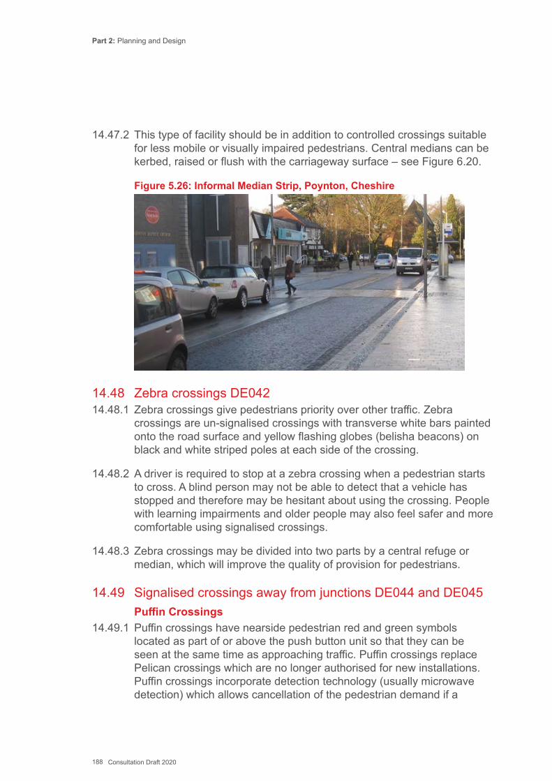
Part 2: Planning and Design
188 Consultation Draft 2020
14.47.2 This type of facility should be in addition to controlled crossings suitable for less mobile or visually impaired pedestrians. Central medians can be kerbed, raised or flush with the carriageway surface – see Figure 6.20.
Figure 5.26: Informal Median Strip, Poynton, Cheshire
14.48 Zebra crossings DE04214.48.1 Zebra crossings give pedestrians priority over other traffic. Zebra
crossings are un-signalised crossings with transverse white bars painted onto the road surface and yellow flashing globes (belisha beacons) on black and white striped poles at each side of the crossing.
14.48.2 A driver is required to stop at a zebra crossing when a pedestrian starts to cross. A blind person may not be able to detect that a vehicle has stopped and therefore may be hesitant about using the crossing. People with learning impairments and older people may also feel safer and more comfortable using signalised crossings.
14.48.3 Zebra crossings may be divided into two parts by a central refuge or median, which will improve the quality of provision for pedestrians.
14.49 Signalised crossings away from junctions DE044 and DE045Puffin Crossings
14.49.1 Puffin crossings have nearside pedestrian red and green symbols located as part of or above the push button unit so that they can be seen at the same time as approaching traffic. Puffin crossings replace Pelican crossings which are no longer authorised for new installations. Puffin crossings incorporate detection technology (usually microwave detection) which allows cancellation of the pedestrian demand if a
Part 2: Planning and Design
189 Consultation Draft 2020
pedestrian crosses after pressing the button, but before the green man has activated. Additionally, the detectors are used to measure the speed at which pedestrians are crossing and can automatically adjust the time allowed to cross the road. A Puffin crossing has the same light sequence as traffic signal junctions (i.e. no flashing amber road traffic signal/flashing green man, as used at Pelicans).
Ped-X Crossings14.49.2 A Ped-X crossing is similar to a Puffin crossing in terms of signal
sequence and detection, but uses farside pedestrian signal aspects. ‘Countdown’ displays which show the time in seconds to the end of the crossing period, can be used with Ped-X crossings. Ped-X crossings are more suited to busy locations where pedestrians may have difficulty seeing the nearside indicators due to crowding.
Toucan Crossings14.49.3 Toucan crossings are shared pedestrian and cycle crossings, and
are similar to Puffin crossings, but with additional red and green cycle symbols. Toucan crossings may have either nearside or farside aspects, and may also include countdown displays.
14.50 Crossings at signal-controlled junctions14.50.1 Pedestrian and cycle crossing facilities can be incorporated into signal-
controlled junctions by providing the appropriate signals. Crossings within signalised junctions may have nearside or far side aspects, and combined pedestrian and cycle crossings.
14.50.2 Pedestrian (and cycle if appropriate) crossing facilities should normally be provided on all arms of a junction. The number of separate crossing stages that a pedestrian/cyclist has to use to cross should be minimised.
14.50.3 The crossing times should be long enough to enable all pedestrians (particularly older people) to cross the road in an unhurried manner. Research by University College London has revealed that a walking speed 1.2m/s, which is often used to set the length of pedestrian stages, is too fast for 85% of women and 76% of men aged 65 and over. Crossing timings can accommodate slower pedestrians with the use of detectors and extensions. Where signal stage timings are fixed, slower walking speeds should be considered if there are significant numbers of elderly or less able people in the locality.
Part 2: Planning and Design
190 Consultation Draft 2020
14.50.4 Signalised crossings may be divided into discrete sections using refuges, with each part of the crossing operating on different stages of the signals for traffic capacity reasons. Such crossings are normally staggered so that pedestrians recognise each part of the crossing as separate, although there are examples of straight-ahead signalised crossings with wide central refuges that operate under separate stages. Staggered crossings involve additional delay and deviation from the desire line, particularly where the stagger is large. Straight ahead crossings are more convenient for pedestrians and should be used wherever possible.
14.50.5 Audible and tactile signals should be provided for sensory impaired pedestrians. The volume of an audible signal can be manually adjusted to suit the environment. Where there are several crossings in proximity, standard audible signals may cause confusion. Bleep and sweep audible signals can be provided. These use a directional speaker and an adjustable volume to assist pedestrians in the vicinity of the crossing.
14.50..6 Tactile signals are rotating cones located on the underside of the push button unit. Care should be taken to ensure that pedestrians can reach the rotating cone and access the crossing without being obstructed by any guard rail. Rotating cones are always placed on the right-hand side of a crossing.
14.50.7 Pedestrian countdown timers can be installed at pedestrian facilities at traffic signals. These provide a display that tells pedestrians how many seconds are left for them to cross. The countdown timers remove uncertainty for pedestrians and can therefore help improve pedestrian comfort and the efficiency of traffic signal timings. Pedestrian countdown timers can only be used at crossings with far side pedestrian signals with fixed ‘black-out’ times.
14.51 Cycle priority crossings DE03714.51.1 Where a cycle route crosses a relatively lightly trafficked street it should
preferably be given priority over the road. It should be clear to motorists that they must give way, and there must be sufficient visibility between the cycle track and carriageway.
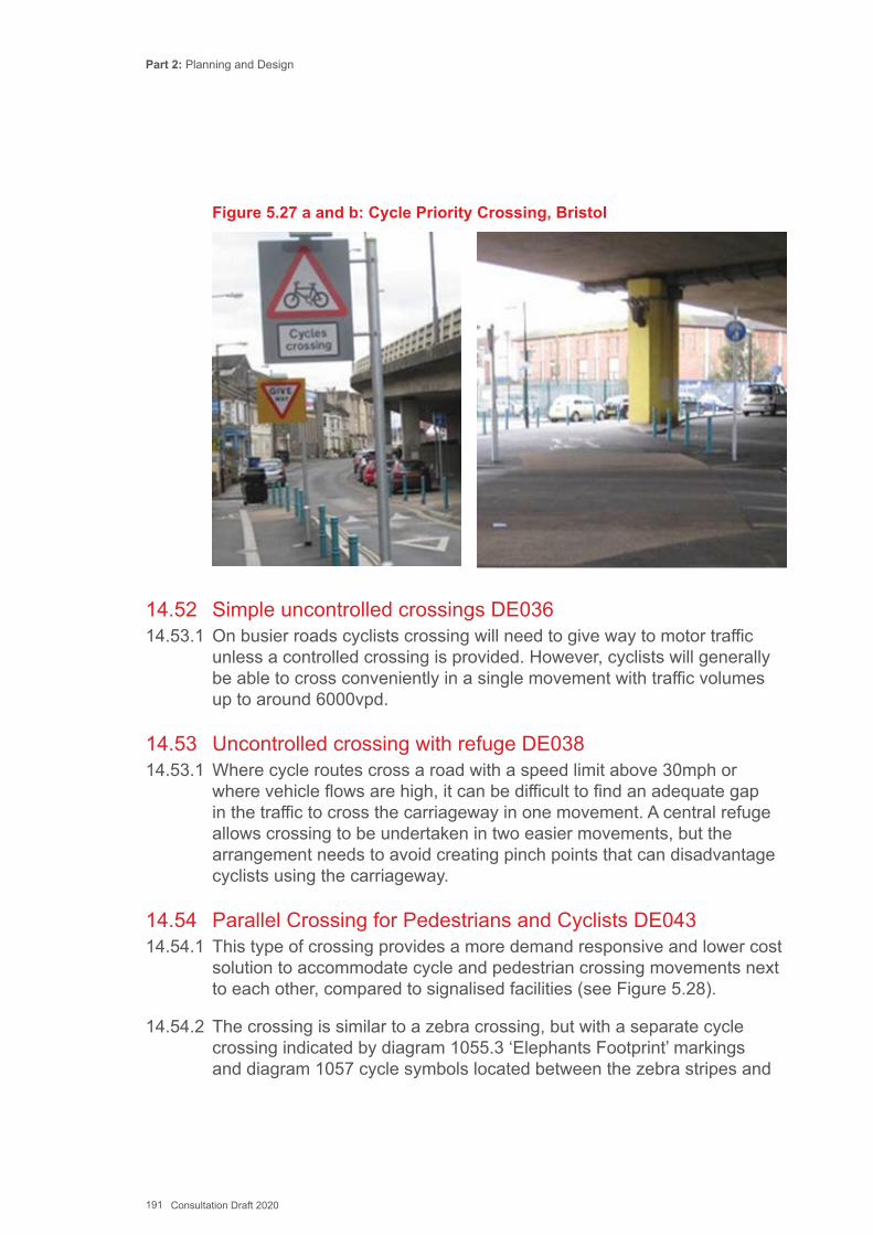
Part 2: Planning and Design
191 Consultation Draft 2020
Figure 5.27 a and b: Cycle Priority Crossing, Bristol
14.52 Simple uncontrolled crossings DE03614.53.1 On busier roads cyclists crossing will need to give way to motor traffic
unless a controlled crossing is provided. However, cyclists will generally be able to cross conveniently in a single movement with traffic volumes up to around 6000vpd.
14.53 Uncontrolled crossing with refuge DE03814.53.1 Where cycle routes cross a road with a speed limit above 30mph or
where vehicle flows are high, it can be difficult to find an adequate gap in the traffic to cross the carriageway in one movement. A central refuge allows crossing to be undertaken in two easier movements, but the arrangement needs to avoid creating pinch points that can disadvantage cyclists using the carriageway.
14.54 Parallel Crossing for Pedestrians and Cyclists DE04314.54.1 This type of crossing provides a more demand responsive and lower cost
solution to accommodate cycle and pedestrian crossing movements next to each other, compared to signalised facilities (see Figure 5.28).
14.54.2 The crossing is similar to a zebra crossing, but with a separate cycle crossing indicated by diagram 1055.3 ‘Elephants Footprint’ markings and diagram 1057 cycle symbols located between the zebra stripes and
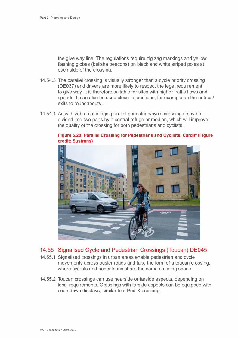
Part 2: Planning and Design
192 Consultation Draft 2020
the give way line. The regulations require zig zag markings and yellow flashing globes (belisha beacons) on black and white striped poles at each side of the crossing.
14.54.3 The parallel crossing is visually stronger than a cycle priority crossing (DE037) and drivers are more likely to respect the legal requirement to give way. It is therefore suitable for sites with higher traffic flows and speeds. It can also be used close to junctions, for example on the entries/ exits to roundabouts.
14.54.4 As with zebra crossings, parallel pedestrian/cycle crossings may be divided into two parts by a central refuge or median, which will improve the quality of the crossing for both pedestrians and cyclists.
Figure 5.28: Parallel Crossing for Pedestrians and Cyclists, Cardiff (Figure credit: Sustrans)
14.55 Signalised Cycle and Pedestrian Crossings (Toucan) DE04514.55.1 Signalised crossings in urban areas enable pedestrian and cycle
movements across busier roads and take the form of a toucan crossing, where cyclists and pedestrians share the same crossing space.
14.55.2 Toucan crossings can use nearside or farside aspects, depending on local requirements. Crossings with farside aspects can be equipped with countdown displays, similar to a Ped-X crossing.
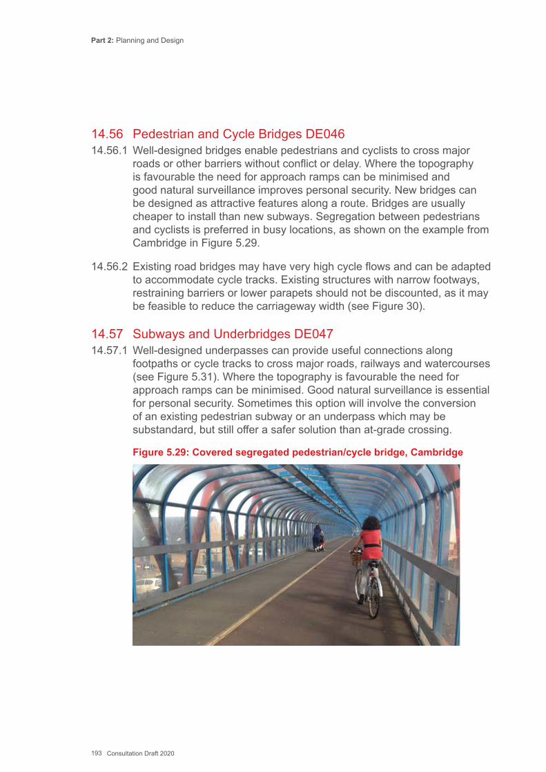
Part 2: Planning and Design
193 Consultation Draft 2020
14.56 Pedestrian and Cycle Bridges DE04614.56.1 Well-designed bridges enable pedestrians and cyclists to cross major
roads or other barriers without conflict or delay. Where the topography is favourable the need for approach ramps can be minimised and good natural surveillance improves personal security. New bridges can be designed as attractive features along a route. Bridges are usually cheaper to install than new subways. Segregation between pedestrians and cyclists is preferred in busy locations, as shown on the example from Cambridge in Figure 5.29.
14.56.2 Existing road bridges may have very high cycle flows and can be adapted to accommodate cycle tracks. Existing structures with narrow footways, restraining barriers or lower parapets should not be discounted, as it may be feasible to reduce the carriageway width (see Figure 30).
14.57 Subways and Underbridges DE04714.57.1 Well-designed underpasses can provide useful connections along
footpaths or cycle tracks to cross major roads, railways and watercourses (see Figure 5.31). Where the topography is favourable the need for approach ramps can be minimised. Good natural surveillance is essential for personal security. Sometimes this option will involve the conversion of an existing pedestrian subway or an underpass which may be substandard, but still offer a safer solution than at-grade crossing.
Figure 5.29: Covered segregated pedestrian/cycle bridge, Cambridge
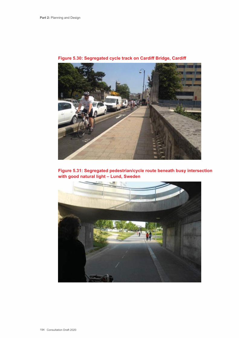
Part 2: Planning and Design
194 Consultation Draft 2020
Figure 5.30: Segregated cycle track on Cardiff Bridge, Cardiff
Figure 5.31: Segregated pedestrian/cycle route beneath busy intersection with good natural light – Lund, Sweden
Part 2: Planning and Design
195 Consultation Draft 2020
14.58 Wheeling Ramps DE04814.58.1 Flights of steps are sometimes unavoidable where a cycle route has
been introduced on a historic path. Wheeling ramps should be added to one or both sides of the flights using steel sections or by forming them in concrete. These facilities will be inaccessible to some cycle users and an alternative route avoiding the steps should be signed where available.
14.59 Cyclists at Priority Junctions14.59.1 The rules for priority at major/minor arm junctions are indicated through
traffic signs and markings. Priority is normally given to the dominant traffic flow. Occasionally the dominant flow for cyclists may be different from that of motor traffic. If the cycle flow is also greater than that of motor traffic, it may be feasible to alter priority in favour of the cycle route.
14.59.2 Four overriding principles underpin the design of priority junctions that are safe and suitable for cyclists using the carriageway:
▪ Low speeds – on approaches and through the junction; ▪ Good intervisibility; ▪ Single lane approaches; ▪ Designs that facilitate correct positioning and offer protection for right
turns from the major arm.
14.59.3 The following design details are recommended:
▪ Change the priority to assist the major cycle flow and reduce traffic speeds. This is typically used on low-traffic streets (up to 3000vpd) where there is not a dominant traffic flow, and may need kerb deflection to support compliance. Changes in priority can signal a change in movement and place function and can support environmental enhancements;
▪ Minimise kerb radii particularly in urban areas with low flows of medium sized delivery vehicles (e.g. business / industrial parks). Vehicle tracking will be necessary to design appropriate radii where regular use by HGVs is intended. It will be acceptable in many 30mph situations for large vehicles to cross centre lines – for further guidance on corner radii refer to Manual for Streets 2 Chapter 9.4. There may need to be some local strengthening of the footway to allow for larger vehicles occasionally overrunning the corner, or the placing of a bollard or other obstruction to ensure that this does not occur;
Part 2: Planning and Design
196 Consultation Draft 2020
▪ Reduce the width of traffic lanes on the approaches to the junction to reduce traffic speeds and reduce crossing distance for pedestrians. This can release space to accommodate cycle lanes or tracks, where needed;
▪ Provide Side Road Entry Treatments or Blended Junction (See 14.32) to reduce the approach speed of vehicles on the minor arm;
▪ Remove long tapers and left-turn lanes, and in particular free- flowing entry and exit slip lanes, from existing junctions and do not use on new layouts where cyclists are on the carriageway. The lanes are hazardous for cyclists.
▪ Provide right turn lanes / ghost islands where cyclists are likely to have to wait for a gap in oncoming traffic to turn right;
▪ Provid14.24). This can help to emphasise route continuity for cycle users and can increase awareness of cyclists to motorists turning across the cycle lane; and
▪ Where a cycle track alongside the carriageway crosses side roads, the aim should be for the cycle track to retain priority and follow the desire line on local roads where this can be accommodated safely.
14.60 Unmarked Informal Junctions DE04814.60.1 Junctions in urban areas, even on relatively busy routes, can be designed
without defined priority, requiring road users to slow down and engage with other road users. The application of these principles (see 14.9 for further guidance) is becoming increasingly common and has been demonstrated to be effective in terms of traffic capacity and safety on four-arm junctions with peak period flows in excess of 2500 vehicles/hour. Examples include junctions in the centre of Coventry, in Poynton in Cheshire (Fig 5.32) and in Bexleyheath in outer London.
14.60.2 Informal junctions can also use circular paving patterns to indicated roundabout-type priority without the use of road markings and signs. These informal roundabouts are discussed in 14.80.
14.60.3 This type of junction can work for cyclists on streets with 20mph speed limits as long as care is taken to ensure that the paths of motor vehicles through the junction are limited to one lane, so that cyclists can adopt a primary position.
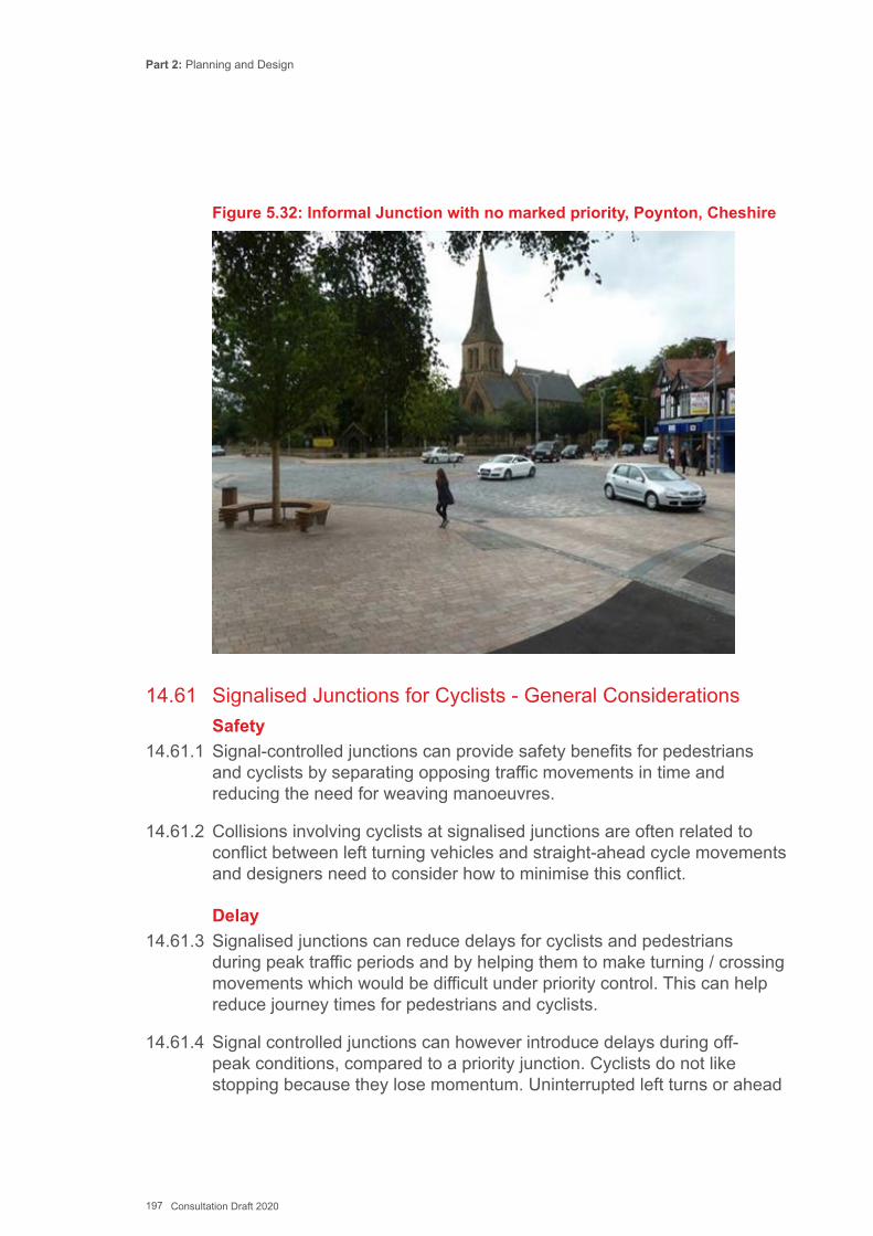
Part 2: Planning and Design
197 Consultation Draft 2020
Figure 5.32: Informal Junction with no marked priority, Poynton, Cheshire
14.61 Signalised Junctions for Cyclists - General ConsiderationsSafety
14.61.1 Signal-controlled junctions can provide safety benefits for pedestrians and cyclists by separating opposing traffic movements in time and reducing the need for weaving manoeuvres.
14.61.2 Collisions involving cyclists at signalised junctions are often related to conflict between left turning vehicles and straight-ahead cycle movements and designers need to consider how to minimise this conflict.
Delay14.61.3 Signalised junctions can reduce delays for cyclists and pedestrians
during peak traffic periods and by helping them to make turning / crossing movements which would be difficult under priority control. This can help reduce journey times for pedestrians and cyclists.
14.61.4 Signal controlled junctions can however introduce delays during off-peak conditions, compared to a priority junction. Cyclists do not like stopping because they lose momentum. Uninterrupted left turns or ahead
Part 2: Planning and Design
198 Consultation Draft 2020
movements at T junctions can be created by including cycle bypasses where space exists. In other situations, priority control may be preferable on cycle routes to minimise the need to stop and start.
14.61.5 The provision of advanced stop lines (ASLs) and lead in lanes at signalised junctions will enable cyclists to bypass queues and position themselves correctly for their turning movement. ASLs are not the only way of providing for cycling however, and can have some disadvantages which are discussed below.
Designing for cyclists’ needs14.61.6 When designing signalised junctions all movements and potential
conflicts by all types of user must be analysed. Most issues can be designed out, if cycle movements are considered early in the design process.
14.61.7 Minor timing changes to existing signal junction operation can provide advantages to cyclists at some junctions, without the need for complex re-signalling works. Traffic modelling can help determine how signal timing changes might affect capacity.
14.61.8 For example, the Connect2 scheme at Finsbury Park adjusted the timings at a signalled junction on Seven Sisters Road such that the minor road approach could be reduced from three to two lanes, thus enabling provision of a cycle track and toucan crossing at that junction without adversely affecting other traffic movements.
14.61.9 Where cyclists share space with pedestrians, rationalisation of street furniture and single stage crossings will help reduce conflict. Parallel crossing facilities for cycles and pedestrians rather than shared can help reduce conflict. Puffin & toucan crossing technology can be used to detect slow moving cyclists and pedestrians through a junction to delay the next signal phase until they are clear.
14.62 Advanced stop lines (ASLs) DE05014.62.1 An Advanced Stop Line (ASL) enables cyclists to take up the appropriate
position in the ‘reservoir’, or waiting area between the two stop lines, ahead of general traffic, before the signals change to green. A cycle feeder lane is normally provided which will enable cyclists to pass queuing motor traffic on the approach to the stop line. ASLs are widely used and some local highways authorities now have a presumption to install ASLs at all signalled junctions.
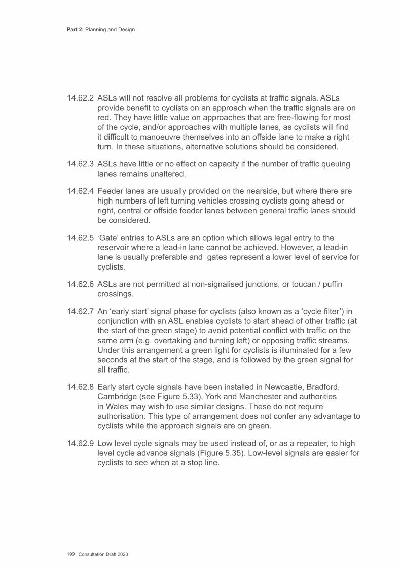
Part 2: Planning and Design
199 Consultation Draft 2020
14.62.2 ASLs will not resolve all problems for cyclists at traffic signals. ASLs provide benefit to cyclists on an approach when the traffic signals are on red. They have little value on approaches that are free-flowing for most of the cycle, and/or approaches with multiple lanes, as cyclists will find it difficult to manoeuvre themselves into an offside lane to make a right turn. In these situations, alternative solutions should be considered.
14.62.3 ASLs have little or no effect on capacity if the number of traffic queuing lanes remains unaltered.
14.62.4 Feeder lanes are usually provided on the nearside, but where there are high numbers of left turning vehicles crossing cyclists going ahead or right, central or offside feeder lanes between general traffic lanes should be considered.
14.62.5 ‘Gate’ entries to ASLs are an option which allows legal entry to the reservoir where a lead-in lane cannot be achieved. However, a lead-in lane is usually preferable and gates represent a lower level of service for cyclists.
14.62.6 ASLs are not permitted at non-signalised junctions, or toucan / puffin crossings.
14.62.7 An ‘early start’ signal phase for cyclists (also known as a ‘cycle filter’) in conjunction with an ASL enables cyclists to start ahead of other traffic (at the start of the green stage) to avoid potential conflict with traffic on the same arm (e.g. overtaking and turning left) or opposing traffic streams. Under this arrangement a green light for cyclists is illuminated for a few seconds at the start of the stage, and is followed by the green signal for all traffic.
14.62.8 Early start cycle signals have been installed in Newcastle, Bradford, Cambridge (see Figure 5.33), York and Manchester and authorities in Wales may wish to use similar designs. These do not require authorisation. This type of arrangement does not confer any advantage to cyclists while the approach signals are on green.
14.62.9 Low level cycle signals may be used instead of, or as a repeater, to high level cycle advance signals (Figure 5.35). Low-level signals are easier for cyclists to see when at a stop line.
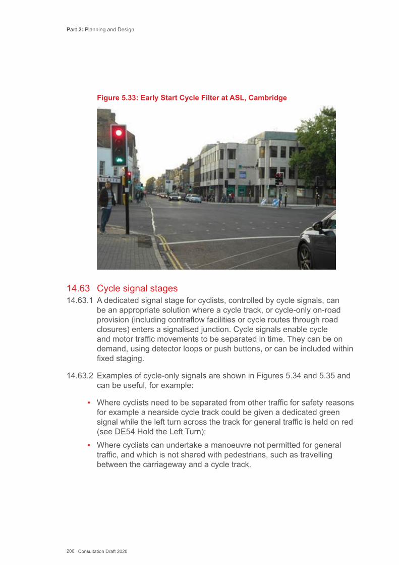
Part 2: Planning and Design
200 Consultation Draft 2020
Figure 5.33: Early Start Cycle Filter at ASL, Cambridge
14.63 Cycle signal stages14.63.1 A dedicated signal stage for cyclists, controlled by cycle signals, can
be an appropriate solution where a cycle track, or cycle-only on-road provision (including contraflow facilities or cycle routes through road closures) enters a signalised junction. Cycle signals enable cycle and motor traffic movements to be separated in time. They can be on demand, using detector loops or push buttons, or can be included within fixed staging.
14.63.2 Examples of cycle-only signals are shown in Figures 5.34 and 5.35 and can be useful, for example:
▪ Where cyclists need to be separated from other traffic for safety reasons for example a nearside cycle track could be given a dedicated green signal while the left turn across the track for general traffic is held on red (see DE54 Hold the Left Turn);
▪ Where cyclists can undertake a manoeuvre not permitted for general traffic, and which is not shared with pedestrians, such as travelling between the carriageway and a cycle track.
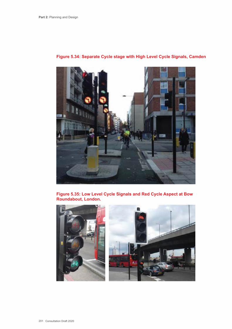
Part 2: Planning and Design
201 Consultation Draft 2020
Figure 5.34: Separate Cycle stage with High Level Cycle Signals, Camden
Figure 5.35: Low Level Cycle Signals and Red Cycle Aspect at Bow Roundabout, London.
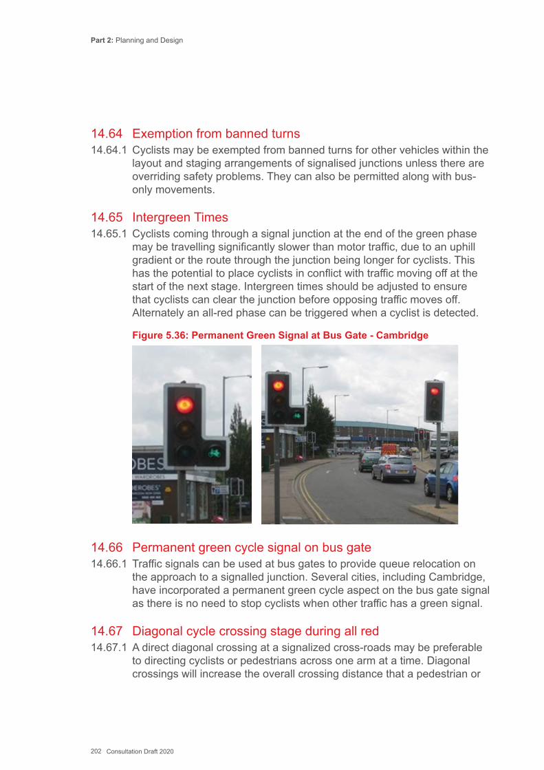
Part 2: Planning and Design
202 Consultation Draft 2020
14.64 Exemption from banned turns14.64.1 Cyclists may be exempted from banned turns for other vehicles within the
layout and staging arrangements of signalised junctions unless there are overriding safety problems. They can also be permitted along with bus-only movements.
14.65 Intergreen Times 14.65.1 Cyclists coming through a signal junction at the end of the green phase
may be travelling significantly slower than motor traffic, due to an uphill gradient or the route through the junction being longer for cyclists. This has the potential to place cyclists in conflict with traffic moving off at the start of the next stage. Intergreen times should be adjusted to ensure that cyclists can clear the junction before opposing traffic moves off. Alternately an all-red phase can be triggered when a cyclist is detected.
Figure 5.36: Permanent Green Signal at Bus Gate - Cambridge
14.66 Permanent green cycle signal on bus gate14.66.1 Traffic signals can be used at bus gates to provide queue relocation on
the approach to a signalled junction. Several cities, including Cambridge, have incorporated a permanent green cycle aspect on the bus gate signal as there is no need to stop cyclists when other traffic has a green signal.
14.67 Diagonal cycle crossing stage during all red14.67.1 A direct diagonal crossing at a signalized cross-roads may be preferable
to directing cyclists or pedestrians across one arm at a time. Diagonal crossings will increase the overall crossing distance that a pedestrian or

Part 2: Planning and Design
203 Consultation Draft 2020
cyclist is required to make in one movement – therefore increasing the length of the red stage for other traffic – but it allows users to replace a “two stage” crossing movement with a “single stage”, reducing their journey times.
14.67.2 At junctions where pedestrians cross on an all red stage, it may be feasible for a diagonal crossing for cyclists to be installed without increasing the duration of the vehicle all–red stage. An example from Cardiff is shown in Figure 5.37.
Figure 5.37: Signalised Diagonal Cycle Crossing, Cardif
14.68 Cycle bypass at traffic signals DE05114.68.1 Where there is space and relatively low levels of pedestrian use, a slip
off in advance of a signalised junction, leading to a short section of cycle track will enable cyclists to bypass a red signal (see Fig 5.38 and 5.39.
14.68.2 This is commonly used:
▪ To turn left; ▪ To continue straight ahead across the head of a T junction.
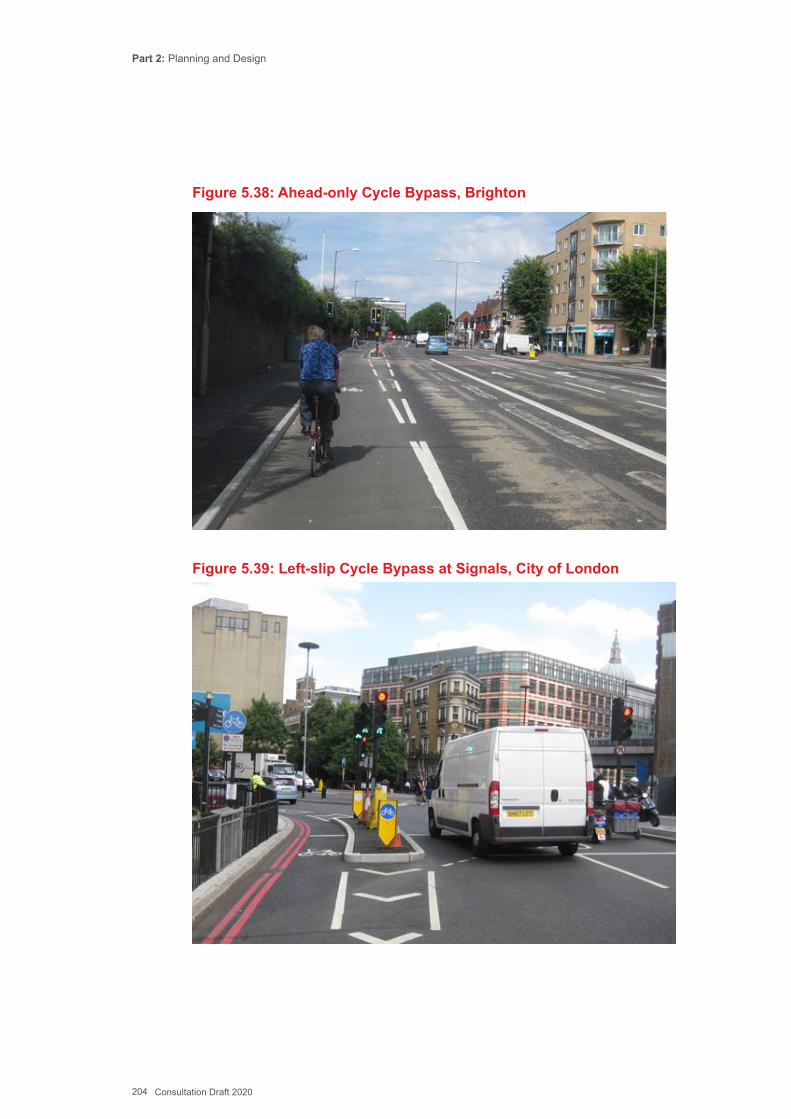
Part 2: Planning and Design
204 Consultation Draft 2020
Figure 5.38: Ahead-only Cycle Bypass, Brighton
Figure 5.39: Left-slip Cycle Bypass at Signals, City of London
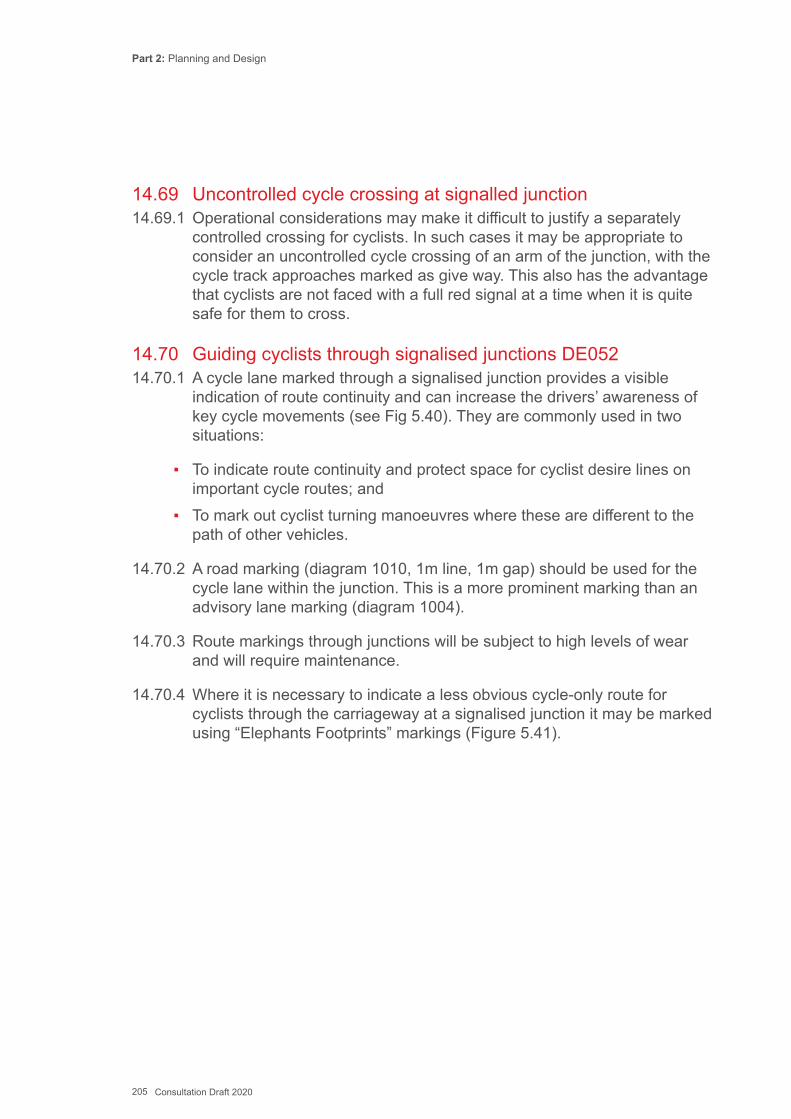
Part 2: Planning and Design
205 Consultation Draft 2020
14.69 Uncontrolled cycle crossing at signalled junction14.69.1 Operational considerations may make it difficult to justify a separately
controlled crossing for cyclists. In such cases it may be appropriate to consider an uncontrolled cycle crossing of an arm of the junction, with the cycle track approaches marked as give way. This also has the advantage that cyclists are not faced with a full red signal at a time when it is quite safe for them to cross.
14.70 Guiding cyclists through signalised junctions DE05214.70.1 A cycle lane marked through a signalised junction provides a visible
indication of route continuity and can increase the drivers’ awareness of key cycle movements (see Fig 5.40). They are commonly used in two situations:
▪ To indicate route continuity and protect space for cyclist desire lines on important cycle routes; and
▪ To mark out cyclist turning manoeuvres where these are different to the path of other vehicles.
14.70.2 A road marking (diagram 1010, 1m line, 1m gap) should be used for the cycle lane within the junction. This is a more prominent marking than an advisory lane marking (diagram 1004).
14.70.3 Route markings through junctions will be subject to high levels of wear and will require maintenance.
14.70.4 Where it is necessary to indicate a less obvious cycle-only route for cyclists through the carriageway at a signalised junction it may be marked using “Elephants Footprints” markings (Figure 5.41).
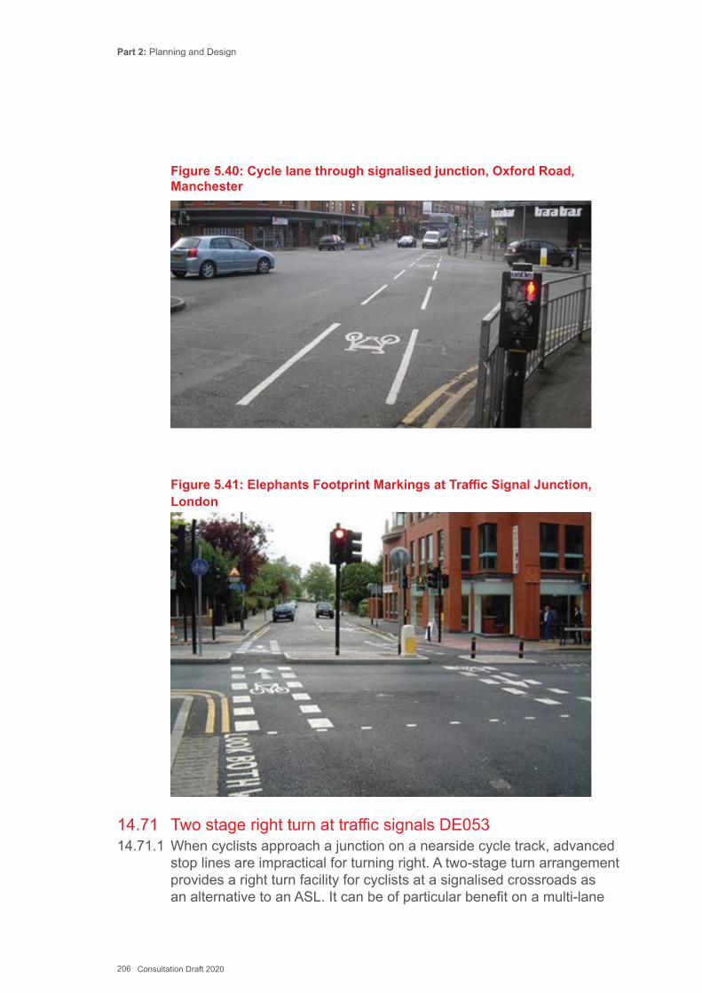
Part 2: Planning and Design
206 Consultation Draft 2020
Figure 5.40: Cycle lane through signalised junction, Oxford Road, Manchester
Figure 5.41: Elephants Footprint Markings at Traffic Signal Junction, London
14.71 Two stage right turn at traffic signals DE05314.71.1 When cyclists approach a junction on a nearside cycle track, advanced
stop lines are impractical for turning right. A two-stage turn arrangement provides a right turn facility for cyclists at a signalised crossroads as an alternative to an ASL. It can be of particular benefit on a multi-lane
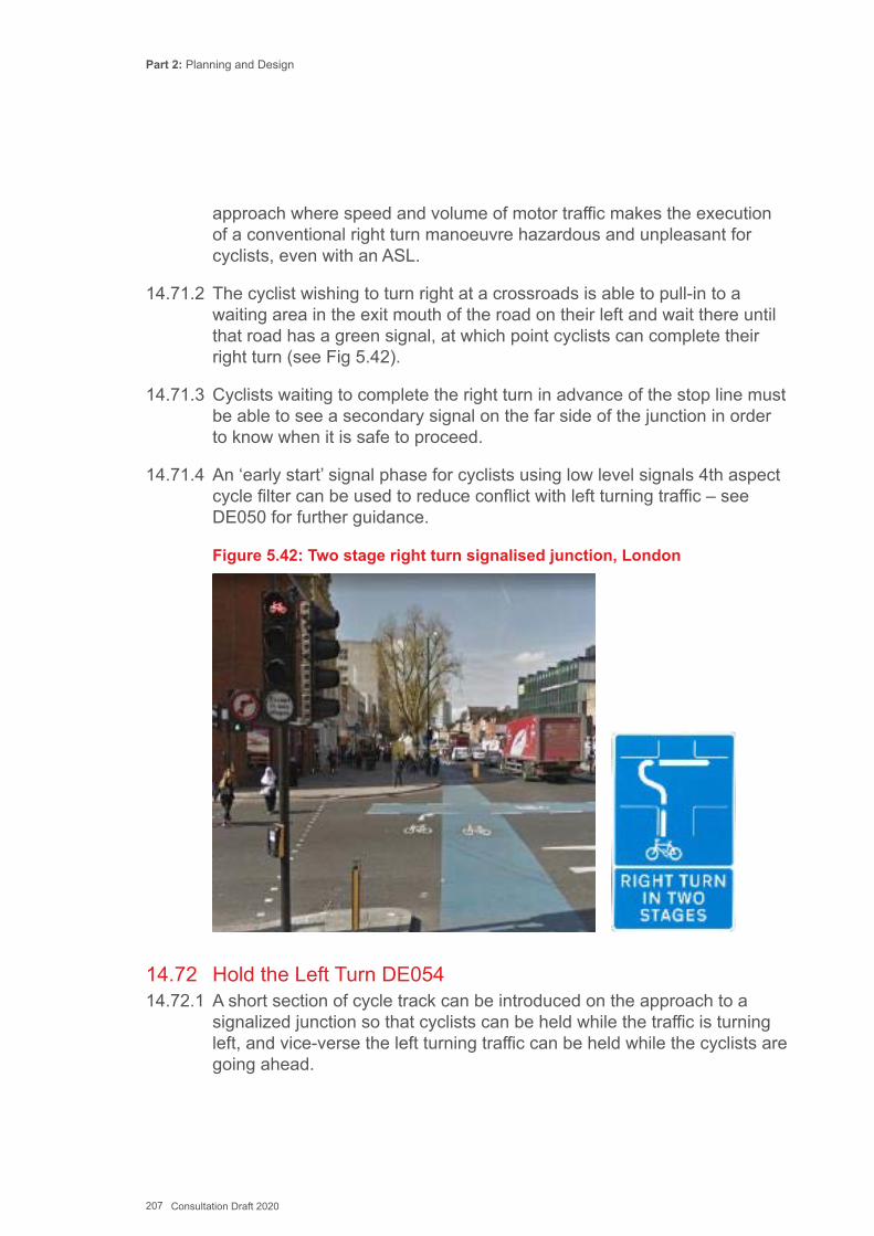
Part 2: Planning and Design
207 Consultation Draft 2020
approach where speed and volume of motor traffic makes the execution of a conventional right turn manoeuvre hazardous and unpleasant for cyclists, even with an ASL.
14.71.2 The cyclist wishing to turn right at a crossroads is able to pull-in to a waiting area in the exit mouth of the road on their left and wait there until that road has a green signal, at which point cyclists can complete their right turn (see Fig 5.42).
14.71.3 Cyclists waiting to complete the right turn in advance of the stop line must be able to see a secondary signal on the far side of the junction in order to know when it is safe to proceed.
14.71.4 An ‘early start’ signal phase for cyclists using low level signals 4th aspect cycle filter can be used to reduce conflict with left turning traffic – see DE050 for further guidance.
Figure 5.42: Two stage right turn signalised junction, London
14.72 Hold the Left Turn DE05414.72.1 A short section of cycle track can be introduced on the approach to a
signalized junction so that cyclists can be held while the traffic is turning left, and vice-verse the left turning traffic can be held while the cyclists are going ahead.
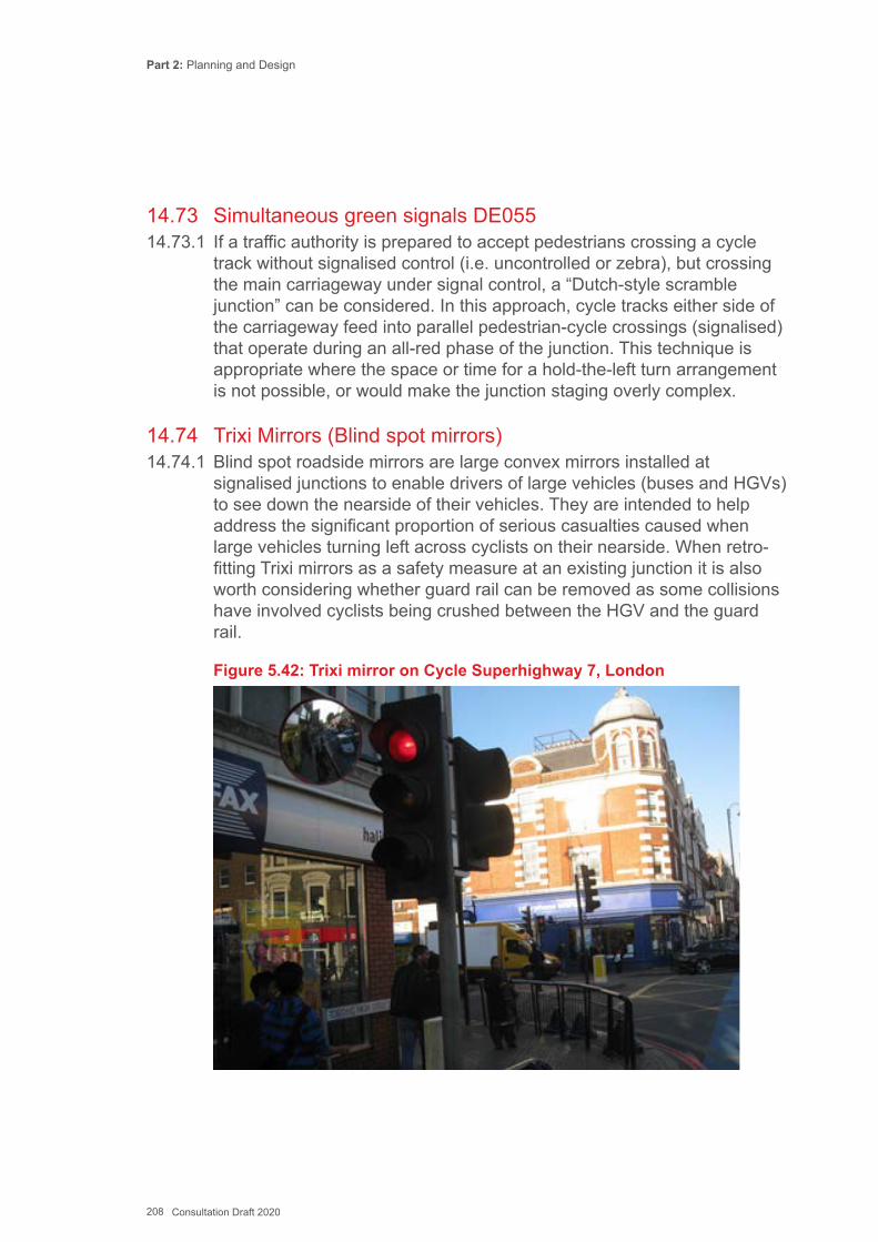
Part 2: Planning and Design
208 Consultation Draft 2020
14.73 Simultaneous green signals DE05514.73.1 If a traffic authority is prepared to accept pedestrians crossing a cycle
track without signalised control (i.e. uncontrolled or zebra), but crossing the main carriageway under signal control, a “Dutch-style scramble junction” can be considered. In this approach, cycle tracks either side of the carriageway feed into parallel pedestrian-cycle crossings (signalised) that operate during an all-red phase of the junction. This technique is appropriate where the space or time for a hold-the-left turn arrangement is not possible, or would make the junction staging overly complex.
14.74 Trixi Mirrors (Blind spot mirrors)14.74.1 Blind spot roadside mirrors are large convex mirrors installed at
signalised junctions to enable drivers of large vehicles (buses and HGVs) to see down the nearside of their vehicles. They are intended to help address the significant proportion of serious casualties caused when large vehicles turning left across cyclists on their nearside. When retro-fitting Trixi mirrors as a safety measure at an existing junction it is also worth considering whether guard rail can be removed as some collisions have involved cyclists being crushed between the HGV and the guard rail.
Figure 5.42: Trixi mirror on Cycle Superhighway 7, London
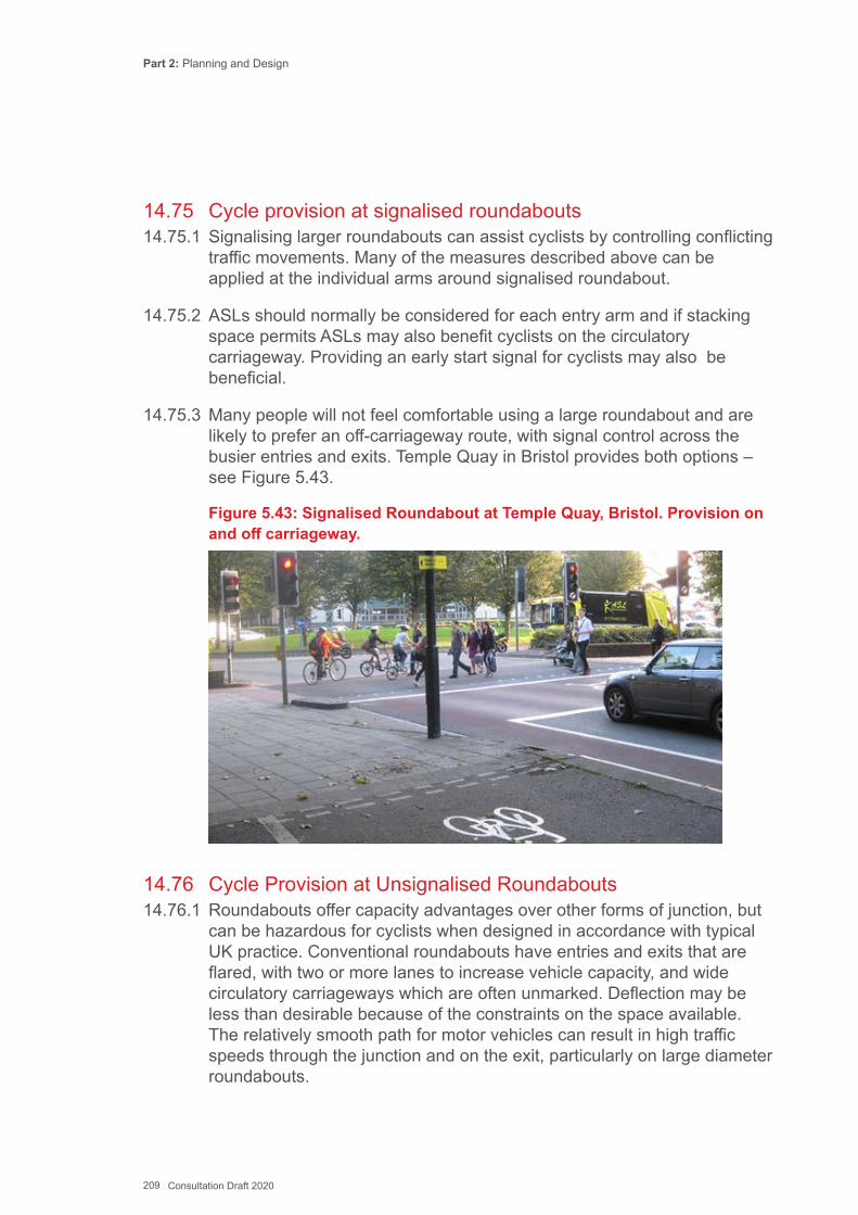
Part 2: Planning and Design
209 Consultation Draft 2020
14.75 Cycle provision at signalised roundabouts14.75.1 Signalising larger roundabouts can assist cyclists by controlling conflicting
traffic movements. Many of the measures described above can be applied at the individual arms around signalised roundabout.
14.75.2 ASLs should normally be considered for each entry arm and if stacking space permits ASLs may also benefit cyclists on the circulatory carriageway. Providing an early start signal for cyclists may also be beneficial.
14.75.3 Many people will not feel comfortable using a large roundabout and are likely to prefer an off-carriageway route, with signal control across the busier entries and exits. Temple Quay in Bristol provides both options – see Figure 5.43.
Figure 5.43: Signalised Roundabout at Temple Quay, Bristol. Provision on and off carriageway.
14.76 Cycle Provision at Unsignalised Roundabouts14.76.1 Roundabouts offer capacity advantages over other forms of junction, but
can be hazardous for cyclists when designed in accordance with typical UK practice. Conventional roundabouts have entries and exits that are flared, with two or more lanes to increase vehicle capacity, and wide circulatory carriageways which are often unmarked. Deflection may be less than desirable because of the constraints on the space available. The relatively smooth path for motor vehicles can result in high traffic speeds through the junction and on the exit, particularly on large diameter roundabouts.
Part 2: Planning and Design
210 Consultation Draft 2020
14.76.2 For slow-moving cyclists, finding a safe position to occupy in a wide circulatory carriageway is difficult, and cyclists are at risk of not being noticed by drivers entering or leaving the junction.
14.76.3 Roundabouts with a dedicated left turn slip lane to increase capacity pose an additional hazard for cyclists, where the lane diverges and where a cyclist travelling straight ahead will leave the roundabout with fast moving traffic coming up on the nearside. They are not recommended for active travel routes wherever on-carriageway cycling can be expected.
14.76.4 Two ways to provide cycle infrastructure at roundabouts are:
▪ Mini or compact roundabouts where traffic volume and speed is relatively low, and the lane width relatively narrow so that cyclists can occupy lane entries, exits and the circulatory carriageway in the primary position; or
▪ At larger roundabouts, where traffic volumes and speeds are higher, provide an off-carriageway track around the junction, with parallel zebra/cycle crossings or signal-controlled crossings of the entries and exits.
14.76.5 Cycle routes can also avoid large roundabouts via grade separated facilities or a completely separate route away from the junction.
14.76.6 The design approaches listed below will help make roundabouts safer for cycling:
▪ Control vehicle speeds to around 20 mph through the junction; ▪ Reduce the amount of space for motor traffic; ▪ Raise driver awareness of cyclists; and ▪ Provide unobstructed passage for cyclists through or around the junction.
14.76.7 Cycle lanes on the outside of the circulatory carriageway are not normally recommended, even on compact roundabouts, since cyclists using them are vulnerable to ‘left hook’ collisions with motor vehicles exiting the junction.
14.77 Mini Roundabout DE05614.77.1 A mini roundabout, where the external diameter is not greater than
15m, can be an alternative to a priority junction. The design of mini roundabouts is included in TD54 of the DMRB. By providing tighter radii, mini roundabouts help reduce speeds, and can be included in traffic calming schemes. Single lane approaches mean that cyclists and motor
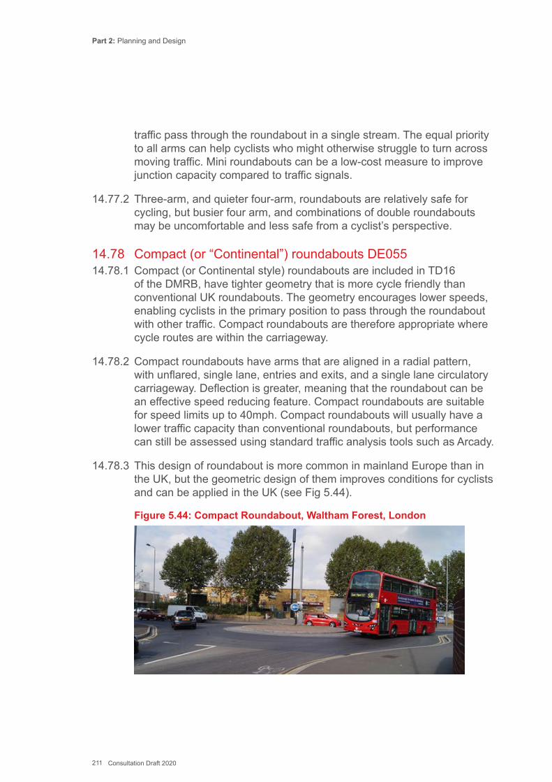
Part 2: Planning and Design
211 Consultation Draft 2020
traffic pass through the roundabout in a single stream. The equal priority to all arms can help cyclists who might otherwise struggle to turn across moving traffic. Mini roundabouts can be a low-cost measure to improve junction capacity compared to traffic signals.
14.77.2 Three-arm, and quieter four-arm, roundabouts are relatively safe for cycling, but busier four arm, and combinations of double roundabouts may be uncomfortable and less safe from a cyclist’s perspective.
14.78 Compact (or “Continental”) roundabouts DE05514.78.1 Compact (or Continental style) roundabouts are included in TD16
of the DMRB, have tighter geometry that is more cycle friendly than conventional UK roundabouts. The geometry encourages lower speeds, enabling cyclists in the primary position to pass through the roundabout with other traffic. Compact roundabouts are therefore appropriate where cycle routes are within the carriageway.
14.78.2 Compact roundabouts have arms that are aligned in a radial pattern, with unflared, single lane, entries and exits, and a single lane circulatory carriageway. Deflection is greater, meaning that the roundabout can be an effective speed reducing feature. Compact roundabouts are suitable for speed limits up to 40mph. Compact roundabouts will usually have a lower traffic capacity than conventional roundabouts, but performance can still be assessed using standard traffic analysis tools such as Arcady.
14.78.3 This design of roundabout is more common in mainland Europe than in the UK, but the geometric design of them improves conditions for cyclists and can be applied in the UK (see Fig 5.44).
Figure 5.44: Compact Roundabout, Waltham Forest, London
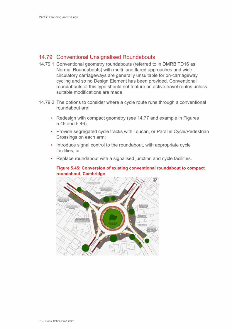
Part 2: Planning and Design
212 Consultation Draft 2020
14.79 Conventional Unsignalised Roundabouts14.79.1 Conventional geometry roundabouts (referred to in DMRB TD16 as
Normal Roundabouts) with multi-lane flared approaches and wide circulatory carriageways are generally unsuitable for on-carriageway cycling and so no Design Element has been provided. Conventional roundabouts of this type should not feature on active travel routes unless suitable modifications are made.
14.79.2 The options to consider where a cycle route runs through a conventional roundabout are:
▪ Redesign with compact geometry (see 14.77 and example in Figures 5.45 and 5.46),
▪ Provide segregated cycle tracks with Toucan, or Parallel Cycle/Pedestrian Crossings on each arm;
▪ Introduce signal control to the roundabout, with appropriate cycle facilities; or
▪ Replace roundabout with a signalised junction and cycle facilities.
Figure 5.45: Conversion of existing conventional roundabout to compact roundabout, Cambridge
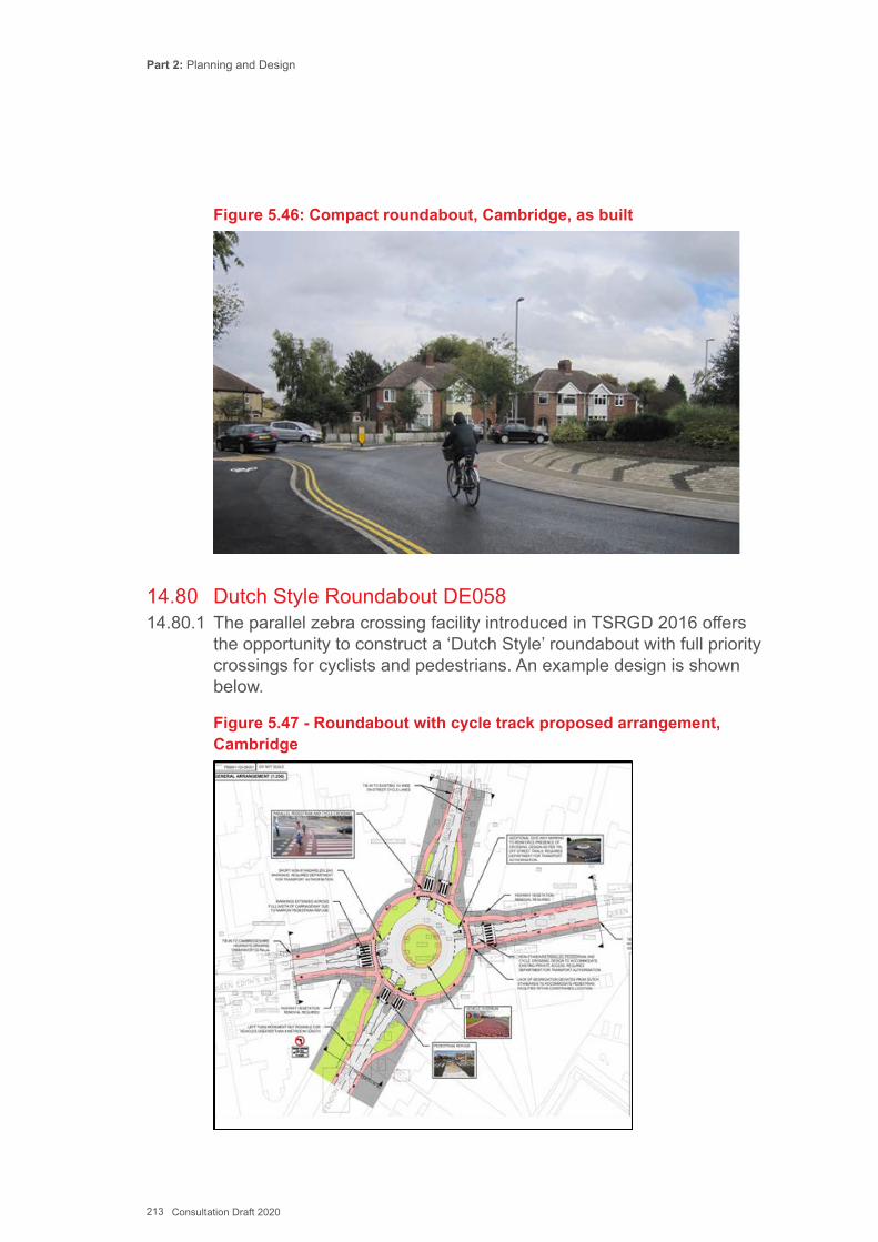
Part 2: Planning and Design
213 Consultation Draft 2020
Figure 5.46: Compact roundabout, Cambridge, as built
14.80 Dutch Style Roundabout DE05814.80.1 The parallel zebra crossing facility introduced in TSRGD 2016 offers
the opportunity to construct a ‘Dutch Style’ roundabout with full priority crossings for cyclists and pedestrians. An example design is shown below.
Figure 5.47 - Roundabout with cycle track proposed arrangement, Cambridge
Part 2: Planning and Design
214 Consultation Draft 2020
14.81 Informal roundabouts at unmarked junctions14.81.1 Some authorities have installed unmarked junctions that are designed
to encourage drivers to adopt circulatory priority, but they are in fact uncontrolled junctions, with no formal road markings or signs. Some Informal junctions (see 14.59) are designed with circular paving patterns to operate this way.
14.81.2 These have been found to work well in capacity and road safety terms at relatively high flows, of up to around 2500 vehicles per hour. The use of circulatory patterns is appropriate where there is a high proportion of turning traffic, which would otherwise tend to give way to oncoming traffic in the centre of the unmarked space.
14.81.3 This type of junction can work well for cyclists as long as care is taken to ensure that vehicles only circulate in one traffic stream and travel slowly, so that cyclists can adopt a primary position when passing through the junction, in a similar way to the compact roundabout.

Part 2: Planning and Design
215 Consultation Draft 2020
Key ReferencesCardiff Council (2011) Cardiff Cycle Design GuideChartered Institution of Highways and Transportation (2010) Manual for Streets 2CROW (2016) Design Manual for Bicycle TrafficDepartment for Transport (1993) TAL9/93 Cycling in Pedestrian AreasDepartment for Transport (1995) The Assessment of Pedestrian Crossings, LTN 1/95Department for Transport (1995) The Design of Pedestrian Crossings, LTN 2/95Department for Transport (1998) Guidance on the Use of Tactile Paving SurfacesDepartment for Transport (1998) TAL 6/98 Contraflow Cycling Department for Transport (2001) Home Zones – Planning and Design, Traffic Advisory Leaflet 10/01Department for Transport (2002) Inclusive Mobility: A Guide to Best Practice on Access to Pedestrian and Transport Infrastructure,Department for Transport (2002) Home Zones – Public Participation,Traffic Advisory Leaflet 8/02Department for Transport (2006) Mini-roundabouts, Good Practice Guide, CSSDepartment for Transport (2007) Guidance on the use of Tactile Paving SurfacesDepartment for Transport (2007) Manual for Streets, London Department for Transport (2007) Local Transport Note 1/07: Traffic CalmingDepartment for Transport (2008) Traffic Management & Streetscape, LTN 1/08Department for Transport (2008) Mixed Priority Routes: Practitioners’ Guide, LTN 3/08Department for Transport (2008) Cycling Infrastructure Design, LTN 2/08Department for Transport (2012) Shared Use Routes for Pedestrians and Cyclists, LTN 1/12Department for Transport (in draft, 2018) Traffic Signs Manual - Chapter 6: Traffic Control TSO.
Part 2: Planning and Design
216 Consultation Draft 2020
DPTAC (2010) Guidance on home zones - designing for disabled people Guide Dogs, Inclusive StreetsHA (1993) TD36/93 Subways for Pedestrians and Pedal Cyclists HA (2004) BD29/04 Design Criteria for FootbridgesHA (2005) TD27/05 Highway Cross-Chapters and Headroom HA (2007) TD54/07 Design of Mini-roundaboutsHMSO (1997) Zebra, Pelican and Puffin Pedestrian Crossings Regulations and General DirectionsHMSO (2016) Traffic Signs Regulations and General Directions,Institute of Highway Engineers (2002) Home Zone Design GuidelinesCIHT (2000) Guidelines for Providing for Journeys on Foot, Joint Statement on shared surface streetsNational Federation of the Blind (2013), Access for Blind People in Towns www.sustrans/design guidanceTfL (2011) Design Standards for Signal Schemes in London
Part 2: Planning and Design
217 Consultation Draft 2020
This Chapter provides guidance on the integration of walking and cycling with public transport at stops and interchanges.
Chapter 15: Integration with Public Transport
15.1 Introduction15.1.1 Many journeys are short, and the entire trip could be made by walking
and cycling. Longer journeys can combine active travel with public transport. Integration between walking, cycling and public transport can help to reduce dependence on private car use for longer journeys and provides a link to distant employment, services, friends and family for those without access to cars.
15.1.2 Well integrated public transport stops or interchanges – whether rail, bus, taxi or ferry – provide efficient access to and from the interchange, improving the competitive advantage of both modes of transport. Integration therefore offers a beneficial effect of encouraging walking and cycling, increasing patronage of public transport and potentially reducing local and longer-distance car traffic.
15.1.3 Active travel already accounts for a significant proportion of journeys to public transport stops, although there is scope to increase cycling substantially. Compared with walking, cycling increases the 20-minute travel time catchment area to a stop by a factor of around 16, thereby greatly extending the reach of public transport. Improving cycle access to interchanges is therefore a major opportunity to generate new trips or shift trips from car to sustainable modes.
15.1.4 Around 45% of rail passengers in Wales access the station on foot, whereas just 2.7% arrive by cycle. Driving, either parked or dropped off, accounts for about 20% of journeys to rail stations[i].
15.2 Improving Walking Access to Public Transport 15.2.1 Walking to stations requires high quality routes that are well signposted,
well lit, feel secure, are maintained properly; offering direct access from the surrounding area. Public transport interchanges should be a high priority destination when planning the pedestrian network.
15.2.2 Bus stops should feel safe and comfortable. Their position should be considered carefully so that they can be easily accessed on foot by people of all abilities. Their precise location will depend on a range of
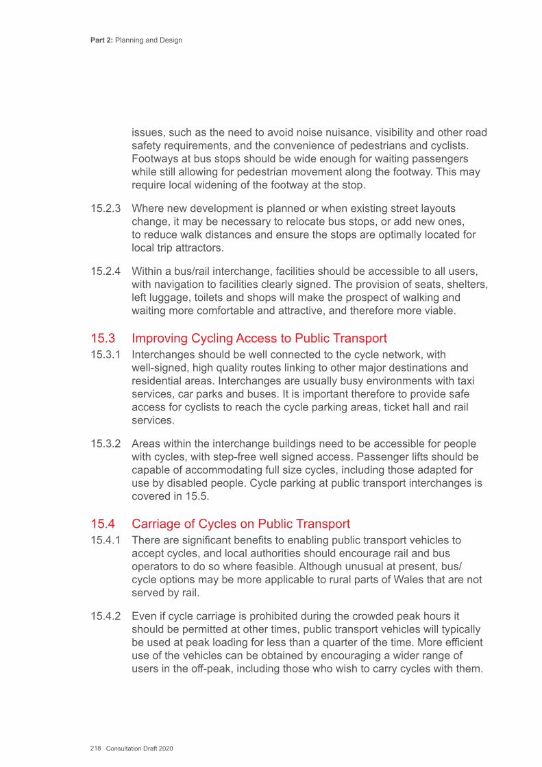
Part 2: Planning and Design
218 Consultation Draft 2020
issues, such as the need to avoid noise nuisance, visibility and other road safety requirements, and the convenience of pedestrians and cyclists. Footways at bus stops should be wide enough for waiting passengers while still allowing for pedestrian movement along the footway. This may require local widening of the footway at the stop.
15.2.3 Where new development is planned or when existing street layouts change, it may be necessary to relocate bus stops, or add new ones, to reduce walk distances and ensure the stops are optimally located for local trip attractors.
15.2.4 Within a bus/rail interchange, facilities should be accessible to all users, with navigation to facilities clearly signed. The provision of seats, shelters, left luggage, toilets and shops will make the prospect of walking and waiting more comfortable and attractive, and therefore more viable.
15.3 Improving Cycling Access to Public Transport 15.3.1 Interchanges should be well connected to the cycle network, with
well-signed, high quality routes linking to other major destinations and residential areas. Interchanges are usually busy environments with taxi services, car parks and buses. It is important therefore to provide safe access for cyclists to reach the cycle parking areas, ticket hall and rail services.
15.3.2 Areas within the interchange buildings need to be accessible for people with cycles, with step-free well signed access. Passenger lifts should be capable of accommodating full size cycles, including those adapted for use by disabled people. Cycle parking at public transport interchanges is covered in 15.5.
15.4 Carriage of Cycles on Public Transport15.4.1 There are significant benefits to enabling public transport vehicles to
accept cycles, and local authorities should encourage rail and bus operators to do so where feasible. Although unusual at present, bus/cycle options may be more applicable to rural parts of Wales that are not served by rail.
15.4.2 Even if cycle carriage is prohibited during the crowded peak hours it should be permitted at other times, public transport vehicles will typically be used at peak loading for less than a quarter of the time. More efficient use of the vehicles can be obtained by encouraging a wider range of users in the off-peak, including those who wish to carry cycles with them.
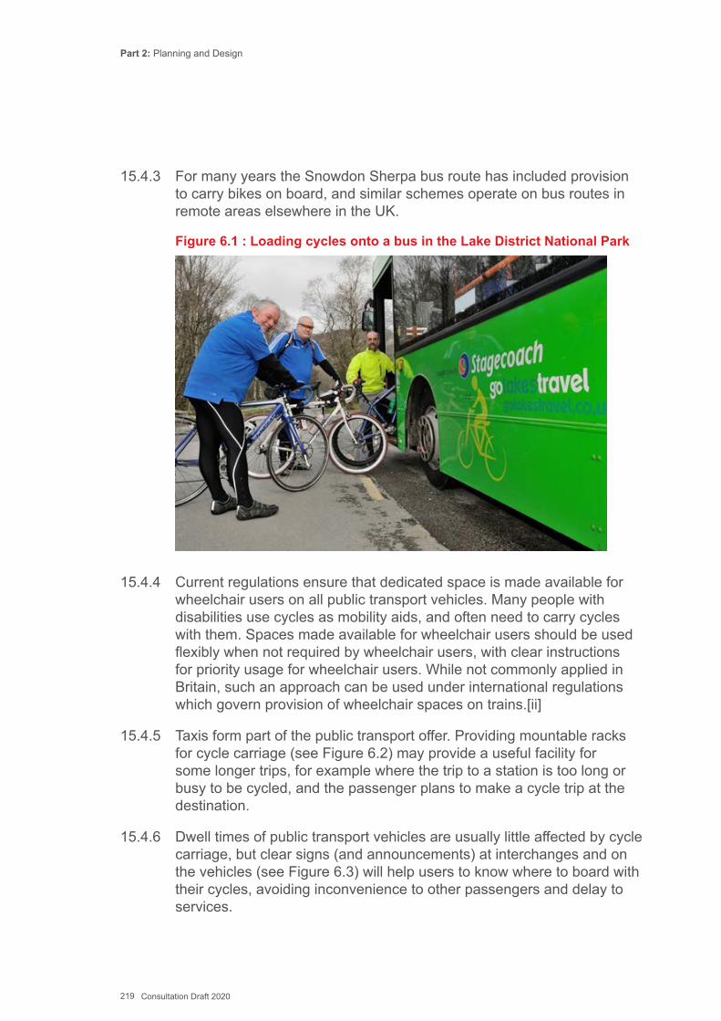
Part 2: Planning and Design
219 Consultation Draft 2020
15.4.3 For many years the Snowdon Sherpa bus route has included provision to carry bikes on board, and similar schemes operate on bus routes in remote areas elsewhere in the UK.
Figure 6.1 : Loading cycles onto a bus in the Lake District National Park
15.4.4 Current regulations ensure that dedicated space is made available for wheelchair users on all public transport vehicles. Many people with disabilities use cycles as mobility aids, and often need to carry cycles with them. Spaces made available for wheelchair users should be used flexibly when not required by wheelchair users, with clear instructions for priority usage for wheelchair users. While not commonly applied in Britain, such an approach can be used under international regulations which govern provision of wheelchair spaces on trains.[ii]
15.4.5 Taxis form part of the public transport offer. Providing mountable racks for cycle carriage (see Figure 6.2) may provide a useful facility for some longer trips, for example where the trip to a station is too long or busy to be cycled, and the passenger plans to make a cycle trip at the destination.
15.4.6 Dwell times of public transport vehicles are usually little affected by cycle carriage, but clear signs (and announcements) at interchanges and on the vehicles (see Figure 6.3) will help users to know where to board with their cycles, avoiding inconvenience to other passengers and delay to services.
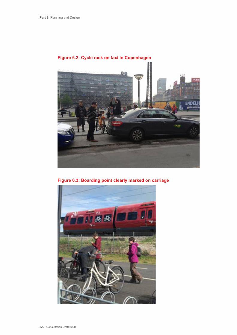
Part 2: Planning and Design
220 Consultation Draft 2020
Figure 6.2: Cycle rack on taxi in Copenhagen
Figure 6.3: Boarding point clearly marked on carriage
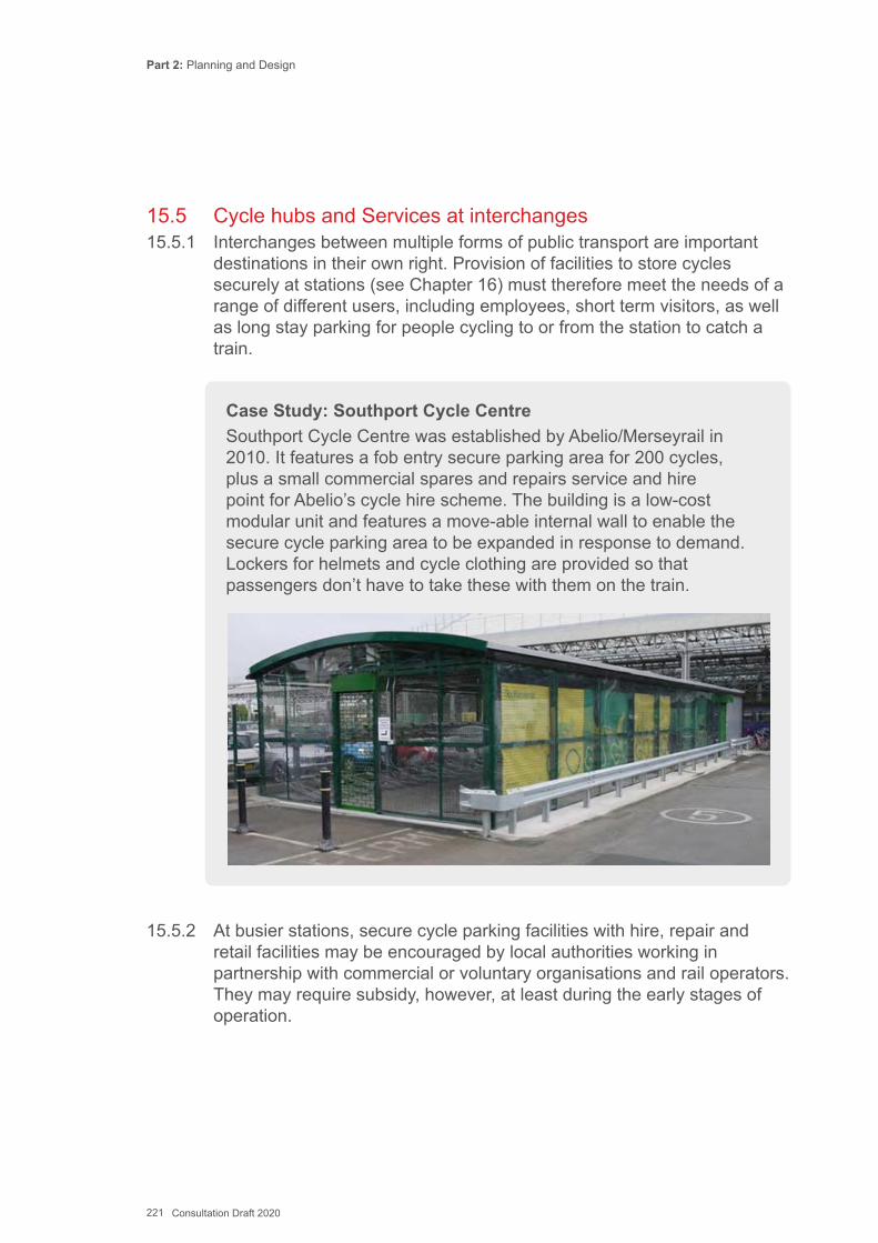
Part 2: Planning and Design
221 Consultation Draft 2020
15.5 Cycle hubs and Services at interchanges15.5.1 Interchanges between multiple forms of public transport are important
destinations in their own right. Provision of facilities to store cycles securely at stations (see Chapter 16) must therefore meet the needs of a range of different users, including employees, short term visitors, as well as long stay parking for people cycling to or from the station to catch a train.
Case Study: Southport Cycle CentreSouthport Cycle Centre was established by Abelio/Merseyrail in 2010. It features a fob entry secure parking area for 200 cycles, plus a small commercial spares and repairs service and hire point for Abelio’s cycle hire scheme. The building is a low-cost modular unit and features a move-able internal wall to enable the secure cycle parking area to be expanded in response to demand. Lockers for helmets and cycle clothing are provided so that passengers don’t have to take these with them on the train.
15.5.2 At busier stations, secure cycle parking facilities with hire, repair and retail facilities may be encouraged by local authorities working in partnership with commercial or voluntary organisations and rail operators. They may require subsidy, however, at least during the early stages of operation.
Part 2: Planning and Design
222 Consultation Draft 2020
15.5.3 Cycle hire provision at major stations, and in locations where tourism potential is greatest, can help to reduce onward private motor travel and support local accessibility. Cycle hire can take the form of part of a city-wide cycle hire network operated through docking stations located at frequent intervals (as in Cardiff and Swansea – see Figure 6.4), as part of a ‘Cycle Hub’ where cycles are hired and returned to the same place, or a ‘pop-up’ seasonal business (e.g. summer rentals at a tourist destination such as a promenade or in a national park). Some systems, such as the Brompton Dock, offer cycles for hire on an automated basis, which reduces operating overheads.
15.5.4 Docked systems may be operated by a smartcard that is valid for other local transport, via an on-street payment terminal or via a smartphone system. The advantage is that the cycles must be returned to a dedicated parking bay (or the user will be charged for the cost of the cycle). The disadvantage is that the pattern of cycle trips is often uneven, necessitating redistributing cycles around the system with a larger vehicle, which adds to the operating costs, and can be awkward for users wishing to hire or return a bike when the nearest bays are either empty or full.
15.5.5 Dockless cycle hire schemes operate via a mobile phone and online subscription, and are generally run by private sector operators. While they can be more convenient for users, the lack of dedicated parking space for the cycles can cause issues for other road users when cycles are parked inconsiderately. Although operators will generally provide more bikes in an area compared to a docked system, it is still necessary to redistribute cycles and to recover cycles that have been abandoned outside the geo-fenced area. Many local authorities have experienced problems both with the operation and longer term sustainability of dockless bike schemes as operators withdraw services at short notice.
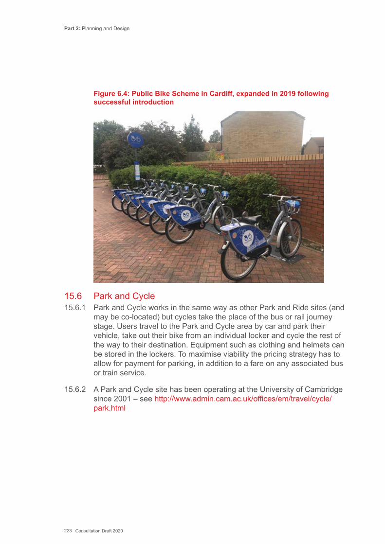
Part 2: Planning and Design
223 Consultation Draft 2020
Figure 6.4: Public Bike Scheme in Cardiff, expanded in 2019 following successful introduction
15.6 Park and Cycle15.6.1 Park and Cycle works in the same way as other Park and Ride sites (and
may be co-located) but cycles take the place of the bus or rail journey stage. Users travel to the Park and Cycle area by car and park their vehicle, take out their bike from an individual locker and cycle the rest of the way to their destination. Equipment such as clothing and helmets can be stored in the lockers. To maximise viability the pricing strategy has to allow for payment for parking, in addition to a fare on any associated bus or train service.
15.6.2 A Park and Cycle site has been operating at the University of Cambridge since 2001 – see http://www.admin.cam.ac.uk/offices/em/travel/cycle/park.html
Part 2: Planning and Design
224 Consultation Draft 2020
Key ReferencesFigures for journeys commencing at stations operated by Arriva Trains Wales from Waves 16-22 of the National Passenger Survey (Passenger Focus).European Commission decision of 21/12/2007 “concerning the technical specification of interoperability relating to ‘persons with reduced mobility’ in the trans-European conventional and high-speed rail system”Green C & Hall P, Better Rail Stations: An Independent Review Presented to Lord Adonis, Secretary of State for Transport. 2009
Part 2: Planning and Design
225 Consultation Draft 2020
This Chapter provides guidance on the design of important related on-street features to support active travel, including seating, landscaping and direction signing. It provides guidance in relation to Section 2(9) of the Active Travel Act. In determining whether anything constitutes related facilities for the purposes of this Act a local authority must have regard to this guidance. Cycle parking and signs for cycle routes are included in more detail elsewhere in this guidance.
Chapter 16: Street Furniture and Cycle Parking
16.1 Introduction16.1.1 Section 2 (8) of the Active Travel Act defines a range of features as
related facilities for the purposes of the Act including:
▪ facilities for shelter, resting or storage, ▪ toilets or washing facilities, ▪ signing, or ▪ other facilities, which are available for use by, or by any description of,
walkers and cyclists using the active travel route.
16.1.2 As noted in Chapter 12, walking and cycling have similarities and yet they have different user needs which also differ with journey purpose. This also applies for related facilities; cyclists may require facilities for showering and secure locations to leave their cycle whilst pedestrians may require public seating and shelters, and places to store coats and umbrellas in the workplace or school. Both pedestrians and cyclists will require clear direction signing, whilst attractive streets with well-maintained planting and public art can contribute to visual amenity (Fig 7.1).
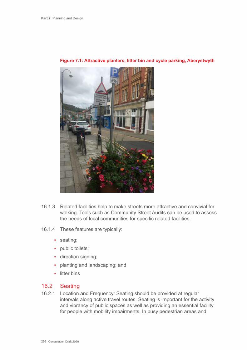
Part 2: Planning and Design
226 Consultation Draft 2020
Figure 7.1: Attractive planters, litter bin and cycle parking, Aberystwyth
16.1.3 Related facilities help to make streets more attractive and convivial for walking. Tools such as Community Street Audits can be used to assess the needs of local communities for specific related facilities.
16.1.4 These features are typically:
▪ seating; ▪ public toilets; ▪ direction signing; ▪ planting and landscaping; and ▪ litter bins
16.2 Seating16.2.1 Location and Frequency: Seating should be provided at regular
intervals along active travel routes. Seating is important for the activity and vibrancy of public spaces as well as providing an essential facility for people with mobility impairments. In busy pedestrian areas and

Part 2: Planning and Design
227 Consultation Draft 2020
key routes where older and disabled people are more likely to use them, resting places should be provided at intervals of around 50m as recommended in Inclusive Mobility. Elsewhere a figure of 100m is appropriate as recommended in Manual for Streets.
16.2.2 More seating should be considered where people congregate, such as public squares, local shops and schools. The provision of seating encourages a range of ‘place’ activities to take place in public space including eating, reading and watching and meeting people. Seating should ideally be placed where there is good natural surveillance and lighting to deter anti-social activity. Seating should allow for street activities to be viewed and can be used to demark areas although it should not hinder pedestrians or form an obstruction.
16.2.3 Design and Layout: Guidance on the design and layout of inclusive seating is given in Inclusive Mobility and BS 8300. In addition to standard height seating, lower seats are useful for people of small stature and children; and higher perches (700mm) against which people half lean and half sit are useful for some disabled people. All seat designs should enable people to easily sit and rise from them. Materials should be in keeping with the design of any adjacent street furniture and easy to maintain.
16.2.4 Seating should include spaces where wheelchair users can sit alongside companions and be located so that when people are seated their feet are not in the pedestrian route. BS 8300 recommends the clear space for access to seating designated for disabled people should be 1.05 metres by 2.3 metres deep to allow for manoeuvring a wheelchair into a designated space from the adjacent footway at right angles.
16.2.5 Seating can be laid out in various ways:
▪ inward looking, to encourage conversation; ▪ outward looking, to see the views; ▪ in the centre of activities, for rest and chance meetings; ▪ at bus stops, for waiting (ideally covered); ▪ in secluded corners, integral with planting.
16.3 Public toilets16.3.1 A lack of clean, accessible and safe toilets impacts everybody, but can
disproportionately affect the most vulnerable pedestrians. Older people, parents and carers with young children, disabled people and people

Part 2: Planning and Design
228 Consultation Draft 2020
with chronic health problems all need easy access to suitably equipped public toilet facilities. Some people may feel unable or reluctant to leave their homes and visit areas where they fear they will not be able to find a public toilet.
16.3.2 Public toilets in town centres, parks and promenades help to encourage people who may need regular toilet access to take exercise and stay physically active. However, public toilets that are badly designed, badly maintained, and poorly located generate a sense of neglect.
16.3.3 Toilets should be no less available for disabled people than for non- disabled people. It is recommended that disabled toilets should be designated as unisex, not integrated with male and female toilets. The provision of unisex toilets allows use by disabled people accompanied by a carer or partner of the opposite sex.
16.3.4 Further guidance regarding toilet design and minimum specifications can be found in Inclusive Mobility and BS8300. Key locations such as public transport hubs should include some changing places that are larger and equipped with benches and hoists to enable carers to assist severely disabled people. Facilities may be provided in partnership with private sector businesses or public transport operators (but this will usually limit hours of opening). Further information is available at http://www.changing-places.org
16.4 Signs for Pedestrians16.4.1 Signing is important for pedestrians to find their way around an unfamiliar
area. Good quality, well placed and clear bilingual signing will enable people to find the most direct route to local destinations. Signing should complement the surrounding environment and be considered at the route or network scale to ensure consistency. Common signs for walking and cycling are in Appendix K.
16.4.2 Signing with, where appropriate, tactile embossed signs and Braille should be clear and give pedestrian users who may not be familiar with the local area some indication of distance and/or time (although will vary according to the walking speed of the individual) to local facilities. Typical destinations for pedestrian signing could include:
▪ public transport interchanges and car parks ▪ libraries ▪ post offices ▪ sports stadia
Part 2: Planning and Design
229 Consultation Draft 2020
▪ parks and leisure centres ▪ main office locations and business parks ▪ religious buildings ▪ hospitals ▪ shopping centres ▪ educational establishments ▪ cultural institutions ▪ tourist advice centres ▪ tourist and leisure attractions ▪ recreational walking and cycling routes
16.4.3 Excessive signing contributes to the accumulation of street clutter. Most people will be aware of facilities close to their own home, but pedestrian signing can be particularly useful where:
▪ people may not be aware of walking routes away from the highway, leading them to use the car instead;
▪ there are likely to be tourists or other visitors unfamiliar with a location such as town and city centres, hospitals, educational, historic and cultural attractions.
16.4.4 Way finding aids, such as the on-street maps and signs used in Cardiff (see Figures 7.2 and 7.3) are good examples of signing which fit well within the existing street environment. They are provided at points of arrival, such as outside train stations, and where routes converge in the city centres.
16.4.5 Tactile versions of maps combined with audible information can be useful to those with sensory impairment and are increasingly provided through mobile and on-line media. Consideration should be given to supplying tactile maps and/or audio trails.
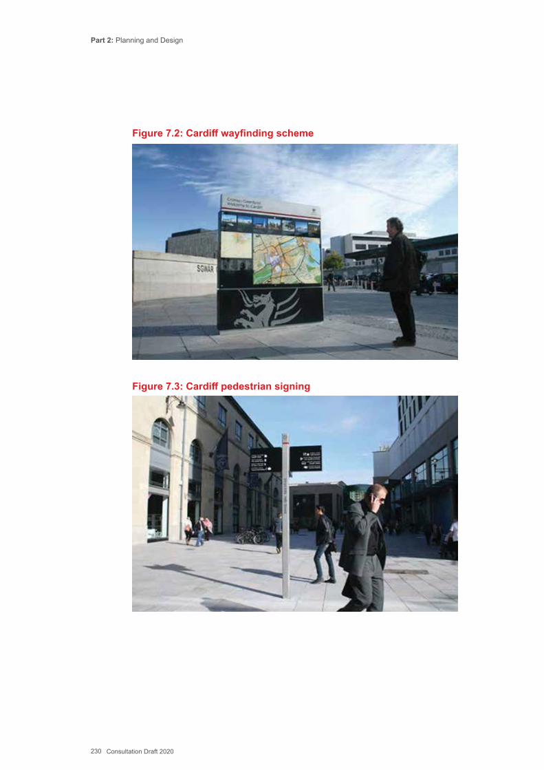
Part 2: Planning and Design
230 Consultation Draft 2020
Figure 7.2: Cardiff wayfinding scheme
Figure 7.3: Cardiff pedestrian signing
Part 2: Planning and Design
231 Consultation Draft 2020
16.4.6 Signs should provide frequent and continuous directions along the entire route, including connections to and from adjacent destinations. Finger posts are commonly used and can be in a variety of styles for pedestrians. The TSRGD applies to cycle signs within the highway so they are less variable. Signing for pedestrians normally provides information on distances in imperial units. Whilst walking times can be useful, they will vary significantly from person to person.
16.4.7 Special paving slabs or plaques can be used to identify marked walking routes. Pavement markings and insets will only be useful to visually impaired people with sufficient residual vision. Generally the signs do not have sufficient distinctive texture or contrast to be identified underfoot or by cane.
16.4.8 Tactile guidance paving is useful for blind pedestrians, as specified in the UK Department for Transport Guidance on the use of tactile paving surfaces. Further guidance regarding accessible signing can be found in Sign Design Guide – a guide to inclusive signing, published by the Sign Design Society, http://www.signdesignsociety.co.uk
16.4.9 Street name plates are help with navigation and should be provided in a consistent style in each local authority area, mounted at or below 2.5m where practical. The plates should be provided at both ends of every street (except culs-de-sac). On long streets (where pedestrians are likely to join the street mid–block) name plates may also be provided at junctions with significant side roads; and building numbers may be included on name plates. On wide streets, name plates on both sides would be desirable.
16.4.10 Signed walking routes should always be as direct as possible but must avoid unsafe or poor-quality infrastructure if this cannot be modified.
16.5 Planting and Hard Landscaping16.5.1 Trees and planting can improve the appearance of a street and provide a
valuable barrier between pedestrians and vehicles, enhancing pedestrian safety and comfort. Planting can provide shade, shelter, privacy, spatial containment and separation. Vegetation can also be used to limit forward visibility to help reduce vehicle speeds in traffic calming schemes.
16.5.2 Hard landscaping using paving, textured surfaces, sculpture and architectural features also contributes to making streets more conducive to walking. The design principles and user requirements set out in this guide apply to urban design as well as general highway design.
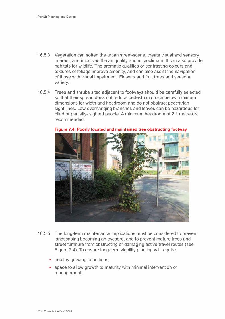
Part 2: Planning and Design
232 Consultation Draft 2020
16.5.3 Vegetation can soften the urban street-scene, create visual and sensory interest, and improves the air quality and microclimate. It can also provide habitats for wildlife. The aromatic qualities or contrasting colours and textures of foliage improve amenity, and can also assist the navigation of those with visual impairment. Flowers and fruit trees add seasonal variety.
16.5.4 Trees and shrubs sited adjacent to footways should be carefully selected so that their spread does not reduce pedestrian space below minimum dimensions for width and headroom and do not obstruct pedestrian sight lines. Low overhanging branches and leaves can be hazardous for blind or partially- sighted people. A minimum headroom of 2.1 metres is recommended.
Figure 7.4: Poorly located and maintained tree obstructing footway
16.5.5 The long-term maintenance implications must be considered to prevent landscaping becoming an eyesore, and to prevent mature trees and street furniture from obstructing or damaging active travel routes (see Figure 7.4). To ensure long-term viability planting will require:
▪ healthy growing conditions; ▪ space to allow growth to maturity with minimal intervention or
management;
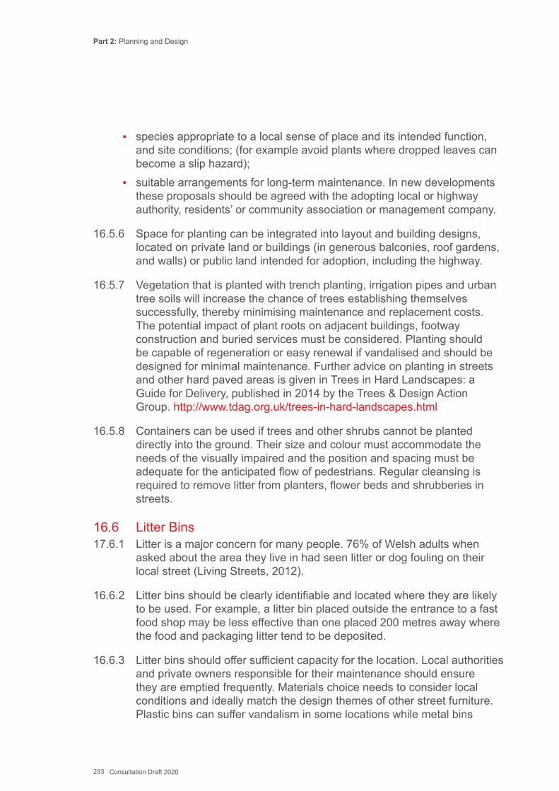
Part 2: Planning and Design
233 Consultation Draft 2020
▪ species appropriate to a local sense of place and its intended function, and site conditions; (for example avoid plants where dropped leaves can become a slip hazard);
▪ suitable arrangements for long-term maintenance. In new developments these proposals should be agreed with the adopting local or highway authority, residents’ or community association or management company.
16.5.6 Space for planting can be integrated into layout and building designs, located on private land or buildings (in generous balconies, roof gardens, and walls) or public land intended for adoption, including the highway.
16.5.7 Vegetation that is planted with trench planting, irrigation pipes and urban tree soils will increase the chance of trees establishing themselves successfully, thereby minimising maintenance and replacement costs. The potential impact of plant roots on adjacent buildings, footway construction and buried services must be considered. Planting should be capable of regeneration or easy renewal if vandalised and should be designed for minimal maintenance. Further advice on planting in streets and other hard paved areas is given in Trees in Hard Landscapes: a Guide for Delivery, published in 2014 by the Trees & Design Action Group. http://www.tdag.org.uk/trees-in-hard-landscapes.html
16.5.8 Containers can be used if trees and other shrubs cannot be planted directly into the ground. Their size and colour must accommodate the needs of the visually impaired and the position and spacing must be adequate for the anticipated flow of pedestrians. Regular cleansing is required to remove litter from planters, flower beds and shrubberies in streets.
16.6 Litter Bins17.6.1 Litter is a major concern for many people. 76% of Welsh adults when
asked about the area they live in had seen litter or dog fouling on their local street (Living Streets, 2012).
16.6.2 Litter bins should be clearly identifiable and located where they are likely to be used. For example, a litter bin placed outside the entrance to a fast food shop may be less effective than one placed 200 metres away where the food and packaging litter tend to be deposited.
16.6.3 Litter bins should offer sufficient capacity for the location. Local authorities and private owners responsible for their maintenance should ensure they are emptied frequently. Materials choice needs to consider local conditions and ideally match the design themes of other street furniture. Plastic bins can suffer vandalism in some locations while metal bins
Part 2: Planning and Design
234 Consultation Draft 2020
corrode quickly in saline environments. Open topped bins are prone to having litter escape from them whilst closed top bins should be regularly cleaned to encourage usage.
16.6.4 Inclusive Mobility and BS8300 provide further guidance on the position, design, and height of bins in streets and other public areas.
16.7 Cycle Count Displays16.7.1 Monitoring cycle use is an important aspect of active travel, recording
changes in behaviour following an infrastructure improvement strengthens the case for further investment and adds to the understanding of overall patterns of transport in a town or city. Automatic cycle counters with a display panel can be installed alongside routes to help encourage users. The displays typically show the number of daily, weekly and cumulative total cyclists per annum.
Figure 7.5 Cycle counter, Manchester
16.8 Cycle Parking16.8.1 Good quality secure cycle parking and route signing helps encourage
cycling and can be provided quickly without significant change to other infrastructure or a lengthy approvals process. Secure cycle parking at
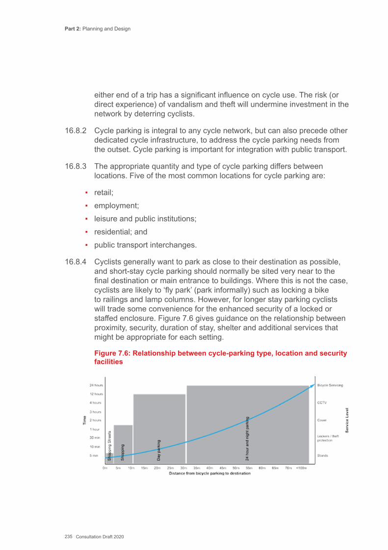
Part 2: Planning and Design
235 Consultation Draft 2020
either end of a trip has a significant influence on cycle use. The risk (or direct experience) of vandalism and theft will undermine investment in the network by deterring cyclists.
16.8.2 Cycle parking is integral to any cycle network, but can also precede other dedicated cycle infrastructure, to address the cycle parking needs from the outset. Cycle parking is important for integration with public transport.
16.8.3 The appropriate quantity and type of cycle parking differs between locations. Five of the most common locations for cycle parking are:
▪ retail; ▪ employment; ▪ leisure and public institutions; ▪ residential; and ▪ public transport interchanges.
16.8.4 Cyclists generally want to park as close to their destination as possible, and short-stay cycle parking should normally be sited very near to the final destination or main entrance to buildings. Where this is not the case, cyclists are likely to ‘fly park’ (park informally) such as locking a bike to railings and lamp columns. However, for longer stay parking cyclists will trade some convenience for the enhanced security of a locked or staffed enclosure. Figure 7.6 gives guidance on the relationship between proximity, security, duration of stay, shelter and additional services that might be appropriate for each setting.
Figure 7.6: Relationship between cycle-parking type, location and security facilities
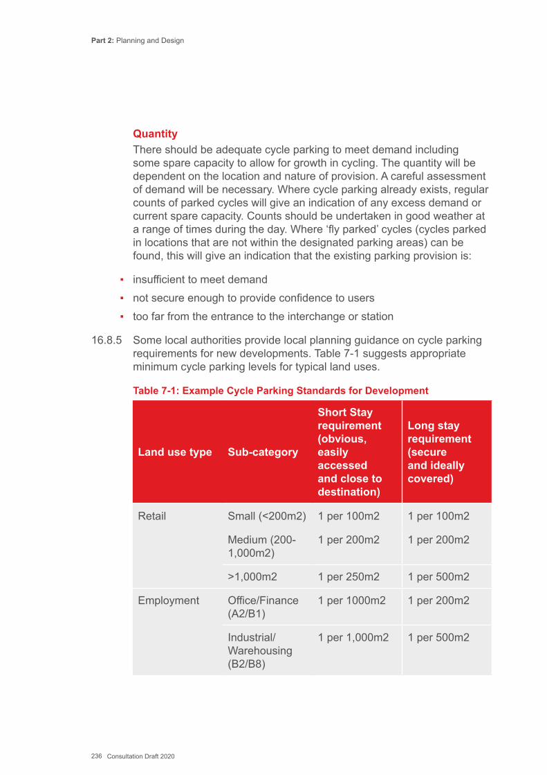
Part 2: Planning and Design
236 Consultation Draft 2020
Quantity There should be adequate cycle parking to meet demand including
some spare capacity to allow for growth in cycling. The quantity will be dependent on the location and nature of provision. A careful assessment of demand will be necessary. Where cycle parking already exists, regular counts of parked cycles will give an indication of any excess demand or current spare capacity. Counts should be undertaken in good weather at a range of times during the day. Where ‘fly parked’ cycles (cycles parked in locations that are not within the designated parking areas) can be found, this will give an indication that the existing parking provision is:
▪ insufficient to meet demand ▪ not secure enough to provide confidence to users ▪ too far from the entrance to the interchange or station
16.8.5 Some local authorities provide local planning guidance on cycle parking requirements for new developments. Table 7-1 suggests appropriate minimum cycle parking levels for typical land uses.
Table 7-1: Example Cycle Parking Standards for Development
Land use type Sub-category
Short Stay requirement (obvious, easily accessed and close to destination)
Long stay requirement (secure and ideally covered)
Retail Small (<200m2) 1 per 100m2 1 per 100m2
Medium (200- 1,000m2)
1 per 200m2 1 per 200m2
>1,000m2 1 per 250m2 1 per 500m2
Employment Office/Finance (A2/B1)
1 per 1000m2 1 per 200m2
Industrial/ Warehousing (B2/B8)
1 per 1,000m2 1 per 500m2
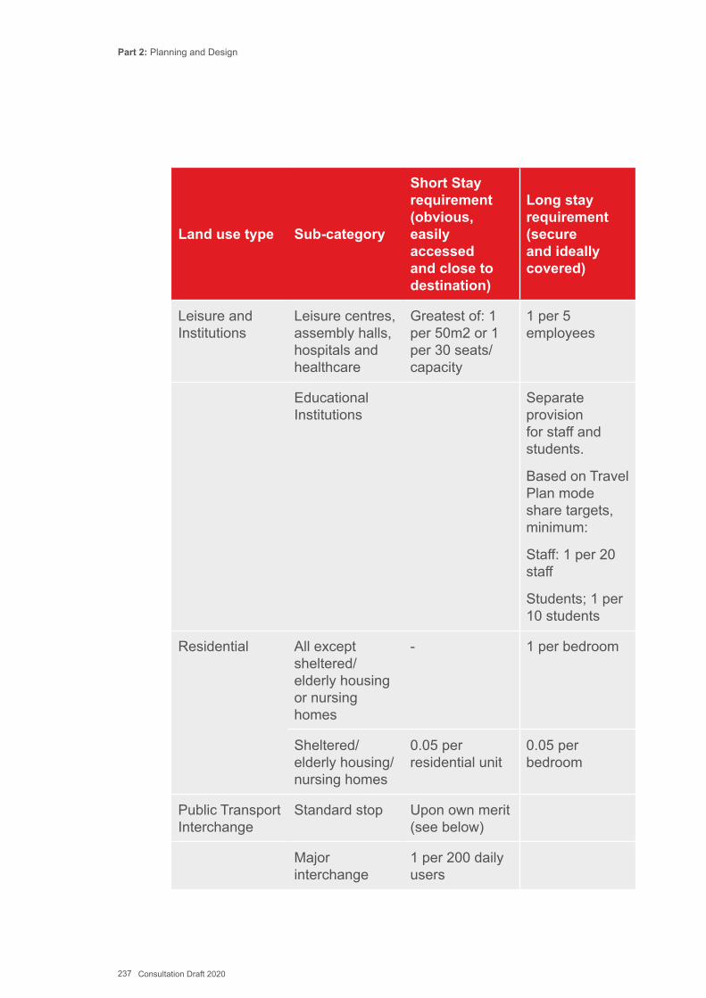
Part 2: Planning and Design
237 Consultation Draft 2020
Land use type Sub-category
Short Stay requirement (obvious, easily accessed and close to destination)
Long stay requirement (secure and ideally covered)
Leisure and Institutions
Leisure centres, assembly halls, hospitals and healthcare
Greatest of: 1 per 50m2 or 1 per 30 seats/ capacity
1 per 5 employees
Educational Institutions
Separate provision for staff and students.
Based on Travel Plan mode share targets, minimum:
Staff: 1 per 20 staff
Students; 1 per 10 students
Residential All except sheltered/ elderly housing or nursing homes
- 1 per bedroom
Sheltered/ elderly housing/ nursing homes
0.05 per residential unit
0.05 per bedroom
Public Transport Interchange
Standard stop Upon own merit (see below)
Major interchange
1 per 200 daily users
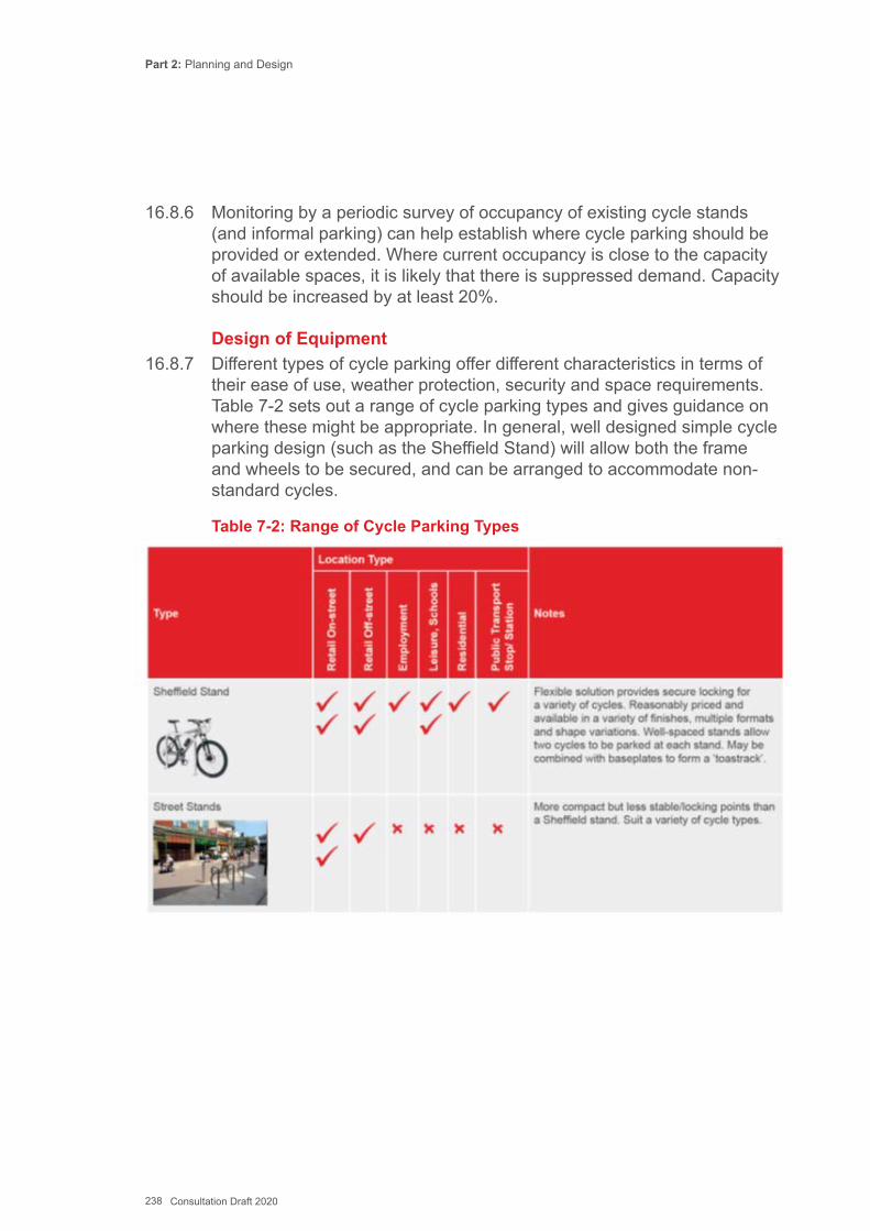
Part 2: Planning and Design
238 Consultation Draft 2020
16.8.6 Monitoring by a periodic survey of occupancy of existing cycle stands (and informal parking) can help establish where cycle parking should be provided or extended. Where current occupancy is close to the capacity of available spaces, it is likely that there is suppressed demand. Capacity should be increased by at least 20%.
Design of Equipment16.8.7 Different types of cycle parking offer different characteristics in terms of
their ease of use, weather protection, security and space requirements. Table 7-2 sets out a range of cycle parking types and gives guidance on where these might be appropriate. In general, well designed simple cycle parking design (such as the Sheffield Stand) will allow both the frame and wheels to be secured, and can be arranged to accommodate non-standard cycles.
Table 7-2: Range of Cycle Parking Types
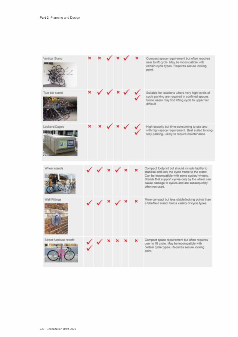
Part 2: Planning and Design
239 Consultation Draft 2020

Part 2: Planning and Design
240 Consultation Draft 2020
Parking at Public Transport Interchanges16.8.8 Providing adequate space for cycle parking at bus, rail or ferry terminals
is vital and should be given a high priority by authorities, working in partnership with the relevant operators and organisations managing the facilities (see also Chapter 15).
16.8.9 A careful assessment of demand will be necessary. Regular counts of parked cycles at existing facilities will give an indication of any excess demand or current spare capacity. Counts should be undertaken in good weather at a range of times during the day when services are operating. Where ‘fly parked’ cycles (cycles parked in locations that are not within the designated parking areas) can be found, this will give an indication that the existing parking provision is:
▪ insufficient to meet demand ▪ not secure enough to provide confidence to users ▪ too far from the entrance to the interchange or station
16.8.10 The nature of public transport trips and the direction of travel should be considered. Outlying stops and stations that serve daily commuters travelling by bus or train to town or city centres are likely to have a demand for daytime parking. Town centre termini or interchanges may attract more overnight parking as cycles are used for the last-mile to/from the workplace. For commuter stations in particular, demand for cycle parking should be provided based on the future anticipated cycle mode share. Daily passenger numbers for every UK station are available from the Office of Rail Regulation (ORR) which can help indicate local demand and potential.
16.8.11 Secure cycle parking can also be provided in small quantities at suburban and rural bus stops, which will greatly increase their catchment area Secure cycle parking can be provided at interchanges with good lighting, CCTV coverage, and the provision of specific equipment such as lockers, or secure entry cycle storage compounds. ‘Cycle Hubs’ which combine secure cycle storage with retail and hire facilities, are discussed in Chapter 15. The hub locations might also serve other purposes such as ticket sales, cycle freight consolidation or coffee shops.
Layout16.8.12 Cycle parking stands should be large enough to accommodate the
dimensions of a typical adult size cycle, as given in Chapter 12. Some of the stands should be designed to accommodate larger cycles for people with disabilities, or cycles constructed for carrying freight or children
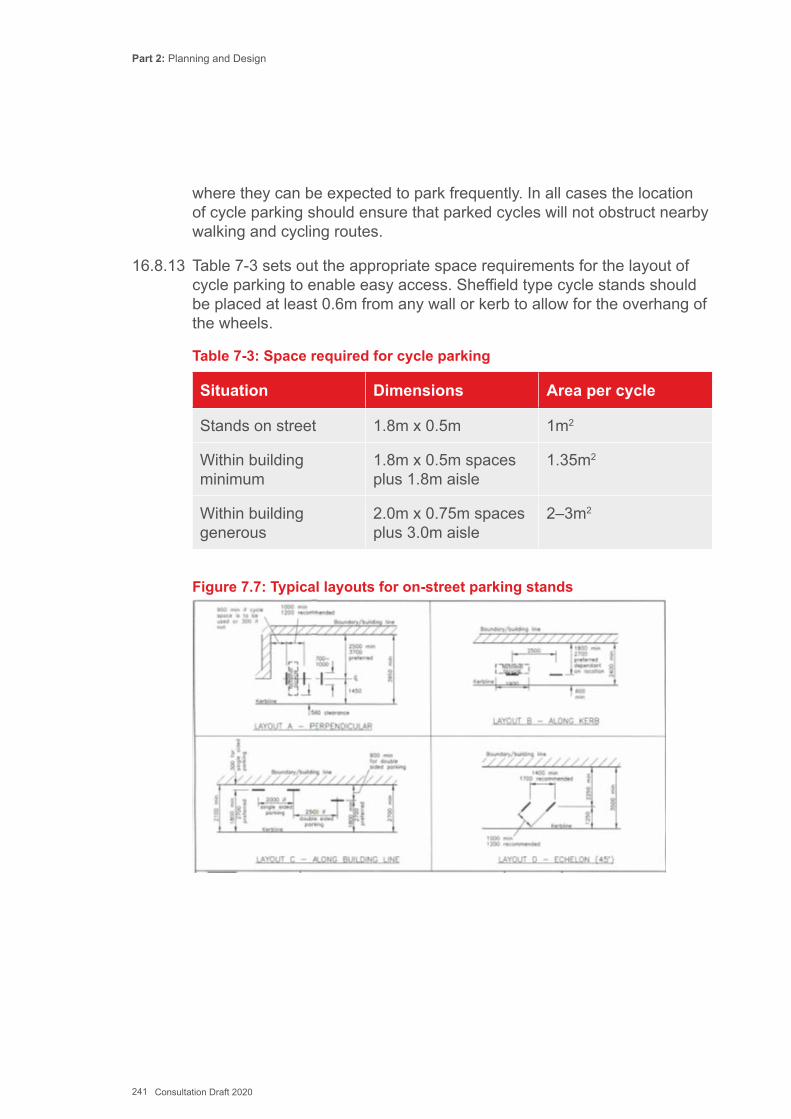
Part 2: Planning and Design
241 Consultation Draft 2020
where they can be expected to park frequently. In all cases the location of cycle parking should ensure that parked cycles will not obstruct nearby walking and cycling routes.
16.8.13 Table 7-3 sets out the appropriate space requirements for the layout of cycle parking to enable easy access. Sheffield type cycle stands should be placed at least 0.6m from any wall or kerb to allow for the overhang of the wheels.
Table 7-3: Space required for cycle parking
Situation Dimensions Area per cycle
Stands on street 1.8m x 0.5m 1m2
Within building minimum
1.8m x 0.5m spaces plus 1.8m aisle
1.35m2
Within building generous
2.0m x 0.75m spaces plus 3.0m aisle
2–3m2
Figure 7.7: Typical layouts for on-street parking stands
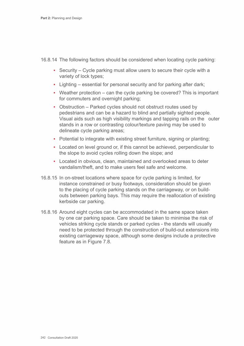
Part 2: Planning and Design
242 Consultation Draft 2020
16.8.14 The following factors should be considered when locating cycle parking:
▪ Security – Cycle parking must allow users to secure their cycle with a variety of lock types;
▪ Lighting – essential for personal security and for parking after dark; ▪ Weather protection – can the cycle parking be covered? This is important
for commuters and overnight parking; ▪ Obstruction – Parked cycles should not obstruct routes used by
pedestrians and can be a hazard to blind and partially sighted people. Visual aids such as high visibility markings and tapping rails on the outer stands in a row or contrasting colour/texture paving may be used to delineate cycle parking areas;
▪ Potential to integrate with existing street furniture, signing or planting; ▪ Located on level ground or, if this cannot be achieved, perpendicular to
the slope to avoid cycles rolling down the slope; and ▪ Located in obvious, clean, maintained and overlooked areas to deter
vandalism/theft, and to make users feel safe and welcome.
16.8.15 In on-street locations where space for cycle parking is limited, for instance constrained or busy footways, consideration should be given to the placing of cycle parking stands on the carriageway, or on build-outs between parking bays. This may require the reallocation of existing kerbside car parking.
16.8.16 Around eight cycles can be accommodated in the same space taken by one car parking space. Care should be taken to minimise the risk of vehicles striking cycle stands or parked cycles - the stands will usually need to be protected through the construction of build-out extensions into existing carriageway space, although some designs include a protective feature as in Figure 7.8.
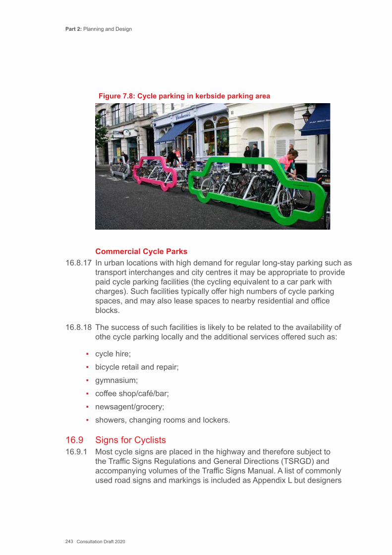
Part 2: Planning and Design
243 Consultation Draft 2020
Figure 7.8: Cycle parking in kerbside parking area
Commercial Cycle Parks16.8.17 In urban locations with high demand for regular long-stay parking such as
transport interchanges and city centres it may be appropriate to provide paid cycle parking facilities (the cycling equivalent to a car park with charges). Such facilities typically offer high numbers of cycle parking spaces, and may also lease spaces to nearby residential and office blocks.
16.8.18 The success of such facilities is likely to be related to the availability of othe cycle parking locally and the additional services offered such as:
▪ cycle hire; ▪ bicycle retail and repair; ▪ gymnasium; ▪ coffee shop/café/bar; ▪ newsagent/grocery; ▪ showers, changing rooms and lockers.
16.9 Signs for Cyclists16.9.1 Most cycle signs are placed in the highway and therefore subject to
the Traffic Signs Regulations and General Directions (TSRGD) and accompanying volumes of the Traffic Signs Manual. A list of commonly used road signs and markings is included as Appendix L but designers
Part 2: Planning and Design
244 Consultation Draft 2020
should always check the latest editions of TSRGD. The advice here and in Appendix L complements that guidance by expanding on some signing issues particular to the design of cycle infrastructure.
16.9.2 Road signs and markings fall into three categories:
▪ Regulatory – enforceable traffic management signing; ▪ Warning and advisory– traffic management signing and markings that are
to warn of hazards and to guide positioning; ▪ Route guidance – location and direction signing.
16.9.3 Signing for cycling may combine more than one of these functions. All signing must be bilingual.
Design Issues16.9.4 There are some cycling- specific signs and markings in each of the above
categories. Cycle specific signing is useful to:
▪ make drivers aware of cycle lanes and tracks reserved for cyclists’ use and assist enforcement;
▪ encourage lane discipline and safe positioning by drivers and cyclists; ▪ warn other road users of the likely presence of cyclists, particularly at
crossings and junctions; ▪ make cyclists aware of rights of way where cycling is permitted or
prohibited; ▪ enable users to follow recommended cycle routes; and ▪ promote cycling and raise its status.
16.9.5 For non-prescribed signs (i.e. signs not included in TSRGD), authorisation is required. In Wales this authorisation is given by the Welsh Ministers.
16.9.6 The latest edition of TSRGD published in 2016 made some important changes over the previous version that address some of the issues around segregated cycle infrastructure and these are incorporated into the drawings in Appendix G. The changes include:
▪ Parallel zebra / cycle crossings and amendments to the zig-zag marking regulations to allow space for a nearside cycle lane
▪ A new sign for contraflow cycling without a cycle lane
Part 2: Planning and Design
245 Consultation Draft 2020
▪ Introduction of ‘Cyclists Rejoin Carriageway’ sign, which was a variant of the ’Cyclists Dismount’ sign with the aim of discouraging the use of the latter.
▪ Allowing an ‘Except Cyclists’ sign to be placed under the No Entry sign (diagram 616)
▪ Low level cycle signals ▪ The use of a red cycle aspect on cycle signals ▪ The use of 1010 road markings on cycle lanes through junctions ▪ The use of ‘Elephants Footprint’ markings through traffic signal junctions ▪ The removal of the need to place vertical cycle route signs to diagram
967 in association with the cycle symbol, diagram 1057
16.9.7 The design of cycle signs should consider the following key principles:
▪ Minimising signing. The potential to improve the clarity and safety of a route through improved design rather than extra signs;
▪ Minimising clutter. The use of signing which minimises street clutter through appropriate scale, good location and integration with existing street furniture;
▪ Signing coherence. The importance of coherent and consistent signing over a whole network and along a particular route;
▪ Maintenance. Minimise the need and cost of future maintenance to ensure that safety and wayfinding remain of a high quality in the long term; and
▪ Value of signing. Good signing should enable cyclists to locate themselves and the intended destination through use of strategic and local destination signing to include key facilities
16.9.8 Many signs are optional rather than mandatory. On the majority of on- street routes cyclists can be adequately catered for within the general traffic signing regime and by exemption to restrictions. It is useful to bear this in mind, as cycle infrastructure can be quite sign intensive and, if not carefully designed, can create unnecessary visual intrusion. Overuse of coloured surfacing adds to this. Where appropriate, signs should be mounted on walls, existing posts or other street furniture to minimise the number of sign posts on the footway.
Part 2: Planning and Design
246 Consultation Draft 2020
16.9.9 Care should be taken with the design of sign assemblies to reduce the risk of vandalism and sign rotation. Where fingerpost arrangements are proposed, purpose-built products are available which can provide aesthetically pleasing non-rotatable signs. Alternatively, rectangular posts should be used for cycle direction signs as these will help prevent rotation. It is also important to ensure signs are located where they will be visible and not obscured by other signs or vegetation growth.
Route guidance, location, and direction signing16.9.10 Route, location and direction signing creates a usable network for
cycling. It communicates to people where it is possible to travel and how much more direct these options can be than the alternative car or public transport journey. They are also essential to direct and reassure people who are not familiar with the area. Not all signing used for cycling needs to be specific - well implemented standard signing such as street names and traffic signs provide a foundation on which to make specific additions.
16.9.11 Cycle routes are usually distinguished by white on blue vertical signing with a cycle symbol. Cycle route signing and route confirmation should only be used where routes are direct and convenient and where the journey experience, under normal conditions, is reasonably good.
16.9.12 Along off-highway routes and along back streets, general direction signing is unlikely to be present, and so cycle signs should address the requirements of direction signing as well as route confirmation. This can be done with signs or with road markings. On main road routes vertical signs should be used for direction signing, with a route symbol either on the sign or combined with lane markings to provide route confirmation.
16.9.13 In addition to marking the route itself, signs may be required to direct cyclists onto the route at intermediate locations. Signs may also be required to direct cyclists to destinations along the route or at the end. A specific locality e.g. Abercynon train station should be used even if the cycle route itself does not go all the way there.
16.9.14 Within each area a consistent set of destinations should be used, these will typically be divided into primary, local and supplementary destinations. Examples of these categories are given in Table 7-4.
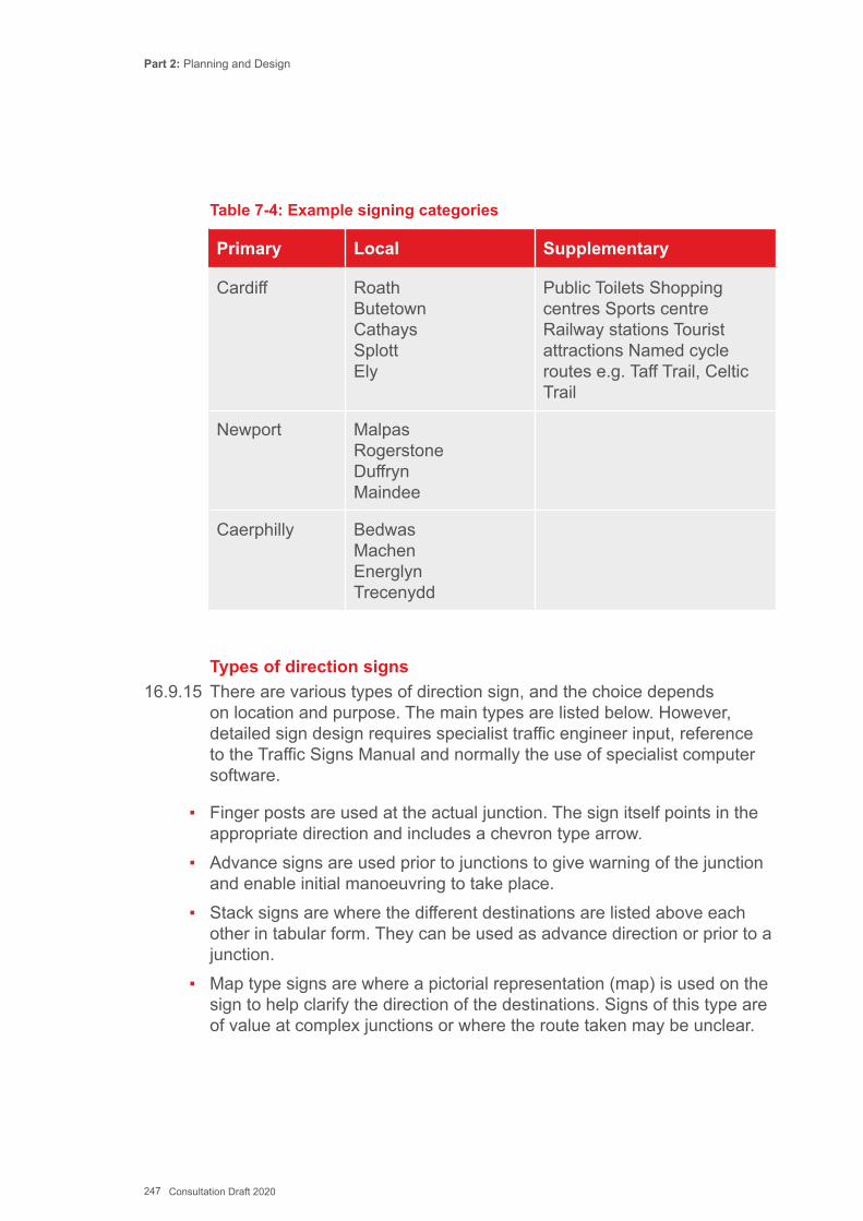
Part 2: Planning and Design
247 Consultation Draft 2020
Table 7-4: Example signing categories
Primary Local Supplementary
Cardiff Roath Butetown Cathays Splott Ely
Public Toilets Shopping centres Sports centre Railway stations Tourist attractions Named cycle routes e.g. Taff Trail, Celtic Trail
Newport Malpas Rogerstone Duffryn Maindee
Caerphilly Bedwas Machen Energlyn Trecenydd
Types of direction signs16.9.15 There are various types of direction sign, and the choice depends
on location and purpose. The main types are listed below. However, detailed sign design requires specialist traffic engineer input, reference to the Traffic Signs Manual and normally the use of specialist computer software.
▪ Finger posts are used at the actual junction. The sign itself points in the appropriate direction and includes a chevron type arrow.
▪ Advance signs are used prior to junctions to give warning of the junction and enable initial manoeuvring to take place.
▪ Stack signs are where the different destinations are listed above each other in tabular form. They can be used as advance direction or prior to a junction.
▪ Map type signs are where a pictorial representation (map) is used on the sign to help clarify the direction of the destinations. Signs of this type are of value at complex junctions or where the route taken may be unclear.
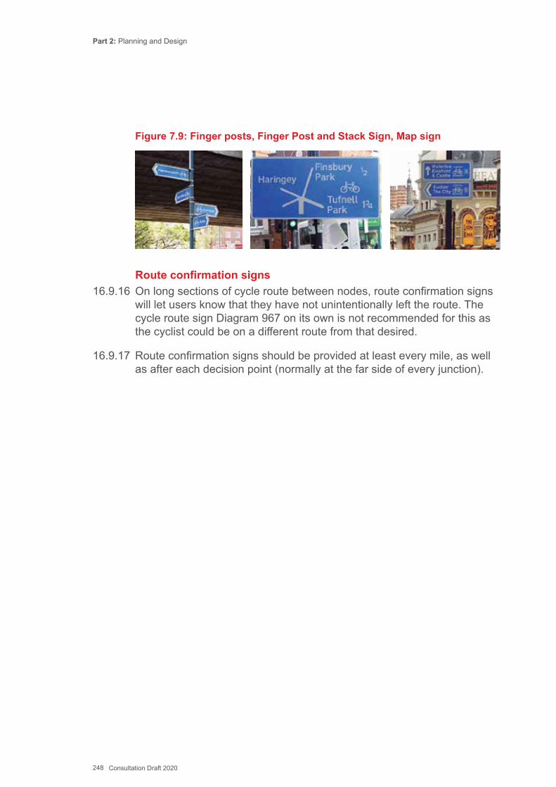
Part 2: Planning and Design
248 Consultation Draft 2020
Figure 7.9: Finger posts, Finger Post and Stack Sign, Map sign
Route confirmation signs16.9.16 On long sections of cycle route between nodes, route confirmation signs
will let users know that they have not unintentionally left the route. The cycle route sign Diagram 967 on its own is not recommended for this as the cyclist could be on a different route from that desired.
16.9.17 Route confirmation signs should be provided at least every mile, as well as after each decision point (normally at the far side of every junction).
Part 2: Planning and Design
249 Consultation Draft 2020
Key References
British Standards Institute (BSI) (2010) BS 8300: 2010 Design of Buildings and their Approaches to Meet the Needs of Disabled PeopleChartered Institution of Highways and Transportation (2000) Guidelines for providing for journeys on footDepartment for Communities and Local Government (2006) Tree Roots in the Built EnvironmentDepartment for Transport (2007) Manual for StreetsDepartment for Communities and Local Government (2008) Improving Public Access to Toilets – A strategic guideDepartment for Environment, Food and Rural Affairs (2005) Achieving improvements in street cleansing & related servicesDepartment for Transport (2002) Inclusive Mobility A Guide to Best Practice on Access to Pedestrian and Transport InfrastructureChartered Institution of Highways and Transportation (1999) Planning for Public Transport in DevelopmentsLiving Streets (2004) Designing Living StreetsSign Design Society and the Royal National Institute of Blind People (2000) Sign Design Guide – a guide to inclusive signageTree and Design Action Group (2014) Trees in Hard landscape: A Guide for Delivery
Part 2: Planning and Design
250 Consultation Draft 2020
Chapter 17: Related Facilities
17.1 Introduction17.1.2 This Guidance focusses mainly on providing defined active travel routes.
However, under Section 7 of the Act authorities must also secure new, and make improvements to, existing active travel routes and related facilities. This will have implications for how authorities go about their general highway duties.
17.1.3 Common legal processes associated with the provision of active travel facilities are given in Appendix C.
17.1.4 Section 9(1) of the Active Travel Act states that the Welsh Ministers and local authorities must take reasonable steps, as far as it is practicable to do so, to enhance the provision made for walkers and cyclists when exercising key functions under various Acts related to highways. The powers are summarised in Tables 1.1 and 1.2 in Chapter 19 and the duties outlined in Chapters 3 and 9 of Part 1: Delivery.
17.1.5 Highway authorities have not always carried out these functions in a way that would be compatible with the aims of the 2014 Act. Some newly-built highways and “improvement” schemes have failed to improve conditions for pedestrians and cyclists – and in some cases have made things worse.
17.1.6 When maintaining, improving or creating new highways, authorities should treat walking and cycling with the same importance and consideration as motorised transport. The duty of authorities under Traffic Management Act 2004 to maintain the free flow of ‘traffic’ includes pedestrian and cycle traffic.
17.2 General Processes for Highway Works17.2.1 Manual for Streets (2007) set out a generic process for all highway
schemes, as shown in Figure 8.1.
This Chapter provides guidance to local authorities when carrying out their general duties and powers in connection with creating, improving, maintaining and managing public highways, whether or not they are defined as an active travel route.
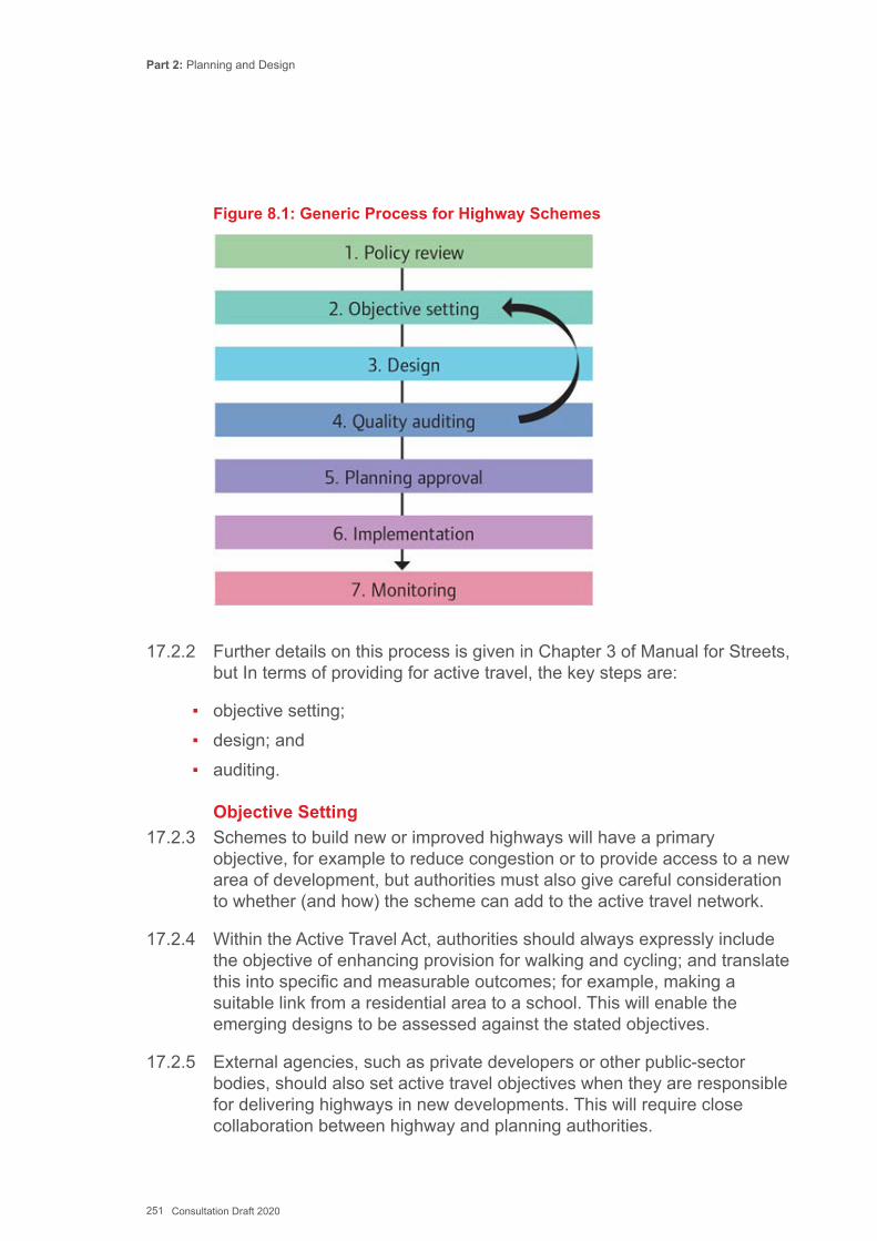
Part 2: Planning and Design
251 Consultation Draft 2020
Figure 8.1: Generic Process for Highway Schemes
17.2.2 Further details on this process is given in Chapter 3 of Manual for Streets, but In terms of providing for active travel, the key steps are:
▪ objective setting; ▪ design; and ▪ auditing.
Objective Setting17.2.3 Schemes to build new or improved highways will have a primary
objective, for example to reduce congestion or to provide access to a new area of development, but authorities must also give careful consideration to whether (and how) the scheme can add to the active travel network.
17.2.4 Within the Active Travel Act, authorities should always expressly include the objective of enhancing provision for walking and cycling; and translate this into specific and measurable outcomes; for example, making a suitable link from a residential area to a school. This will enable the emerging designs to be assessed against the stated objectives.
17.2.5 External agencies, such as private developers or other public-sector bodies, should also set active travel objectives when they are responsible for delivering highways in new developments. This will require close collaboration between highway and planning authorities.
Part 2: Planning and Design
252 Consultation Draft 2020
Design17.2.6 New and improved highways need to strike an appropriate balance
to best meet the various design objectives that have been set. There is sometimes tension between objectives such as increasing motor traffic capacity and providing for pedestrians and cyclists. The statutory obligation to enhance provision for active travel means that this objective should be given a high priority throughout the design process.
17.2.7 Further details on planning networks and design elements to meet the needs of active travel are given in Chapters 13 and 14 respectively.
Auditing17.2.8 Most highway improvement and new-build schemes are subject to a
Road Safety Audit. Authorities should consider whether additional audit and review techniques could be used to check and demonstrate how well a design meets the objectives that were set for it. Given that objectives should include enhancing active travel, the design audit/review process should include assessments of the quality of provision for walking and cycling. The audit tools in Appendix H and I of this Design Guidance may be helpful as a guide. Designs that follow this design guidance should also meet the requirements of any Equality Audit.
17.2.9 Where a Road Safety Audit identifies that a scheme departs from safety related design standard, all options to mitigate for the issues raised should be explored. It is important to remember that designs do not ‘pass’ or ‘fail’ a road safety audit (see Manual for Streets 2).
17.2.10 The level of risk posed by any issues highlighted should also be considered. A formal risk assessment may be useful in considering an appropriate proportionate response to the audit by the design team. It is important that directness and attractiveness along an active travel route is not compromised by an over- cautious approach to road safety, for example by installing unnecessary guardrail or over-engineered crossings.
17.2.11 In situations where there are many competing types of objective (for example in sensitive locations in historic centres), a Quality Audit (QA) may be helpful. Further details of the QA process is given in Traffic Advisory Leaflet 5/11. Cardiff Council uses a Combined User Audit, which is a simplified version of the QA and which considers other aspects of a scheme than simply road safety.

Part 2: Planning and Design
253 Consultation Draft 2020
17.3 Highways Created by Welsh Government and Highway Authorities17.3.1 New roads and streets are created either by authorities themselves using
powers under Part 3 of the Highways Act 1980, or by the private sector by an Agreement under Section 38 of the same Act.
17.3.2 Active travel modes should be integral to planning and design from the outset, rather than being seen as an ‘add-on’ once the needs of motor traffic have been considered. Designers of new highways should consider the five attributes of good walking and cycling routes given in earlier chapters - Coherent, Direct, Safe, Comfortable and Attractive – and find ways to meet them as part of the scheme. Doing this at the feasibility and outline design stage will ensure that sufficient land is acquired to accommodate the active travel designs set out in Chapter 14.
17.3.3 This means that when a new link is first being planned, the opportunity to improve and extend the existing and future network of walking and cycling routes is always taken. In rural areas there may be only low numbers of journeys by foot and cycle but local walking and cycling routes could still be severed, and appropriate mitigation measures should always seek to enhance active travel facilities.
17.3.4 New highways in urban areas will almost always affect large numbers of actual and potential active travel journeys and so designers take great care to identify how the scheme can make them better.
17.3.5 For example, a new town bypass scheme or urban relief road will usually intercept several existing roads and streets leading to the town centre. New enlarged junctions on the new road will present difficulties for pedestrians and cyclists if they are not well designed. In future, Authorities should ensure that provision for convenient active travel along and across new roads is included in designs.
17.3.6 The route of a new highway itself provides an opportunity to add the new alignment into the local active travel network. New highways, even in rural areas, should provide new footways and cycle facilities that are appropriate to the levels of motor traffic and active travel traffic that are anticipated.
17.4 Highways Created by Private Sector Developments17.4.1 New highways are often promoted, funded, designed and built by the
private sector (and by contractors commissioned through health and education authorities) as part of new development schemes. The local
Part 2: Planning and Design
254 Consultation Draft 2020
highway authority is not directly responsible for the scheme, but it can use its powers to control development and approve technical details to fulfil its obligations for cycle and pedestrian friendly designs under the Active Travel Act.
17.4.2 New developments can provide entirely new routes away from the site itself under an agreement to S106 of the Town and Country Planning Act 1990, for example a large housing scheme may fund a village bypass. The new link and its interface with existing routes provides opportunities for new active travel infrastructure.
17.4.3 The new highways created within a development are normally offered for adoption by the local highway authority under Section 38 of the Highways Act.
17.4.4 New highways created within a development for adoption by the local authority will need to comply with local authority design guides. The guidance normally sets out some minimum geometric parameters for roads and streets serving residential and commercial developments. General guidance is included in Manual for Streets 1 and 2, which place emphasis on the needs of pedestrians and cyclists.
17.4.5 The Active Travel Act means that authorities should review their design guidelines for developers to ensure that adequate provision is made for active travel by developers’ design teams (and/or refer developers to comply with the Active Travel Design Guidance). This will require a consideration of the basic elements making up new highways – motor traffic lane widths, cycle lanes/tracks, footways, verges and so on – to ensure that highways on new developments provide appropriate facilities for walking and cycling as a matter of course.
17.4.6 Planning and design of new and improved infrastructure will be led by the Transport Assessment for the new development, which is used to forecast the all-mode travel demands, assess their impact on the surrounding network and design appropriate mitigation measures. It should be noted that smaller developments, on designated active travel routes, which fall below the normal thresholds to provide Transport Assessments should still be required to contribute to active travel improvements.
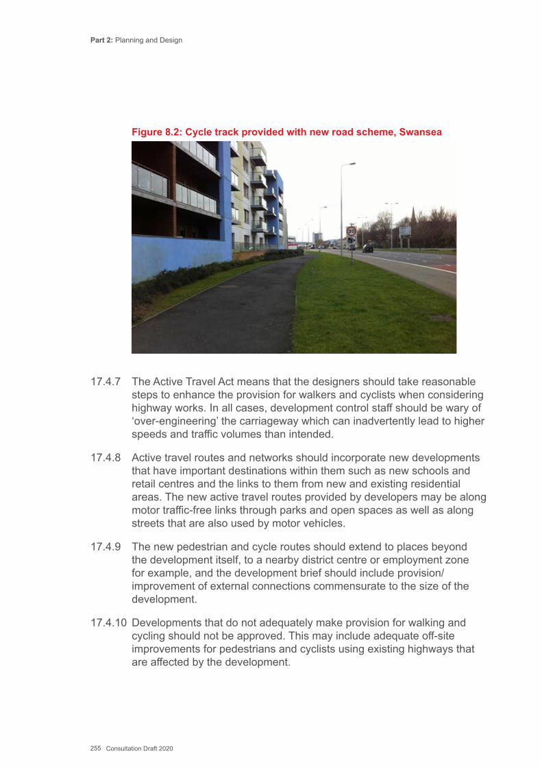
Part 2: Planning and Design
255 Consultation Draft 2020
Figure 8.2: Cycle track provided with new road scheme, Swansea
17.4.7 The Active Travel Act means that the designers should take reasonable steps to enhance the provision for walkers and cyclists when considering highway works. In all cases, development control staff should be wary of ‘over-engineering’ the carriageway which can inadvertently lead to higher speeds and traffic volumes than intended.
17.4.8 Active travel routes and networks should incorporate new developments that have important destinations within them such as new schools and retail centres and the links to them from new and existing residential areas. The new active travel routes provided by developers may be along motor traffic-free links through parks and open spaces as well as along streets that are also used by motor vehicles.
17.4.9 The new pedestrian and cycle routes should extend to places beyond the development itself, to a nearby district centre or employment zone for example, and the development brief should include provision/improvement of external connections commensurate to the size of the development.
17.4.10 Developments that do not adequately make provision for walking and cycling should not be approved. This may include adequate off-site improvements for pedestrians and cyclists using existing highways that are affected by the development.
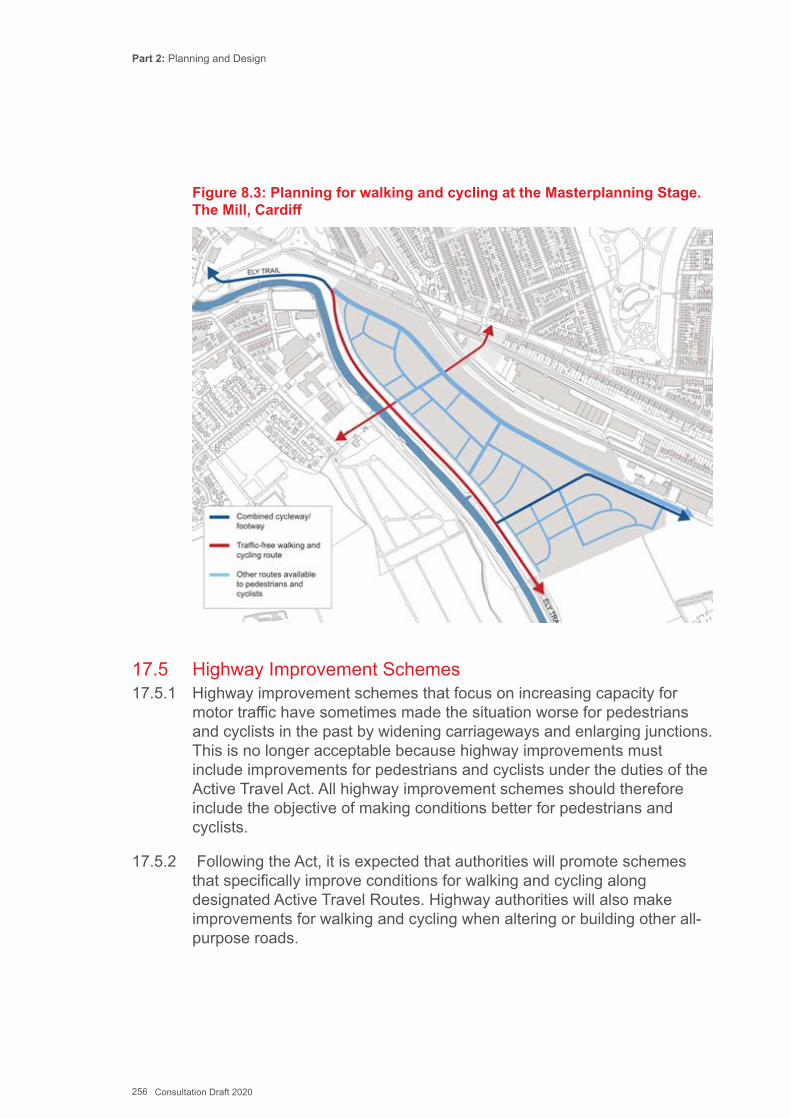
Part 2: Planning and Design
256 Consultation Draft 2020
Figure 8.3: Planning for walking and cycling at the Masterplanning Stage. The Mill, Cardiff
17.5 Highway Improvement Schemes17.5.1 Highway improvement schemes that focus on increasing capacity for
motor traffic have sometimes made the situation worse for pedestrians and cyclists in the past by widening carriageways and enlarging junctions. This is no longer acceptable because highway improvements must include improvements for pedestrians and cyclists under the duties of the Active Travel Act. All highway improvement schemes should therefore include the objective of making conditions better for pedestrians and cyclists.
17.5.2 Following the Act, it is expected that authorities will promote schemes that specifically improve conditions for walking and cycling along designated Active Travel Routes. Highway authorities will also make improvements for walking and cycling when altering or building other all- purpose roads.
Part 2: Planning and Design
257 Consultation Draft 2020
17.5.3 It is intended that better active travel facilities will encourage more people to use these modes; which in turn will reduce the need to travel by motor vehicle and help to reduce the demand for finite road space.
17.5.4 When considering the need for land acquisition when planning new and improved roads, designers should consider the spatial implications of the designs elements described in Chapter 14 and Appendix G.
17.6 Highway Maintenance Schemes17.6.1 Highway maintenance issues are covered in general in Chapter 18, but it
is important to note here that improvements for active travel – particularly cycling - can be achieved at minimal cost during routine maintenance operations.
17.6.2 When road markings are removed during resurfacing, this creates an opportunity to reallocate part of the carriageway to cyclists or to widen existing cycle lanes. General traffic lanes can be narrowed, wide central hatching can be removed, and the resulting space given over to cycle lanes, which can also be protected with light segregation, all at minimal or low cost.
17.6.3 An even lower cost technique, mainly suitable for routes with lower motor traffic volumes and speeds, is to simply not replace centre line markings which has been shown to reduce speeds (Manual for Streets para 9.3.3). Removing centrelines can also enable the provision of advisory cycle lanes with a single all-purpose lane for motor traffic (see DE017 and Figure 8.4).
17.6.4 Resurfacing provides an opportunity to improve the comfort of carriageways for cyclists. As noted in Chapter 18, Stone Mastic Asphalt provides a smoother surface for cycling than Hot Rolled Asphalt.
17.6.5 Maintenance can also provide the opportunity to remove unnecessary or duplicated signing as part of ongoing de-cluttering programmes, and to replace missing or damaged signs on active travel routes.
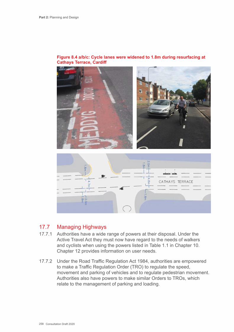
Part 2: Planning and Design
258 Consultation Draft 2020
Figure 8.4 a/b/c: Cycle lanes were widened to 1.8m during resurfacing at Cathays Terrace, Cardiff
17.7 Managing Highways17.7.1 Authorities have a wide range of powers at their disposal. Under the
Active Travel Act they must now have regard to the needs of walkers and cyclists when using the powers listed in Table 1.1 in Chapter 10. Chapter 12 provides information on user needs.
17.7.2 Under the Road Traffic Regulation Act 1984, authorities are empowered to make a Traffic Regulation Order (TRO) to regulate the speed, movement and parking of vehicles and to regulate pedestrian movement. Authorities also have powers to make similar Orders to TROs, which relate to the management of parking and loading.
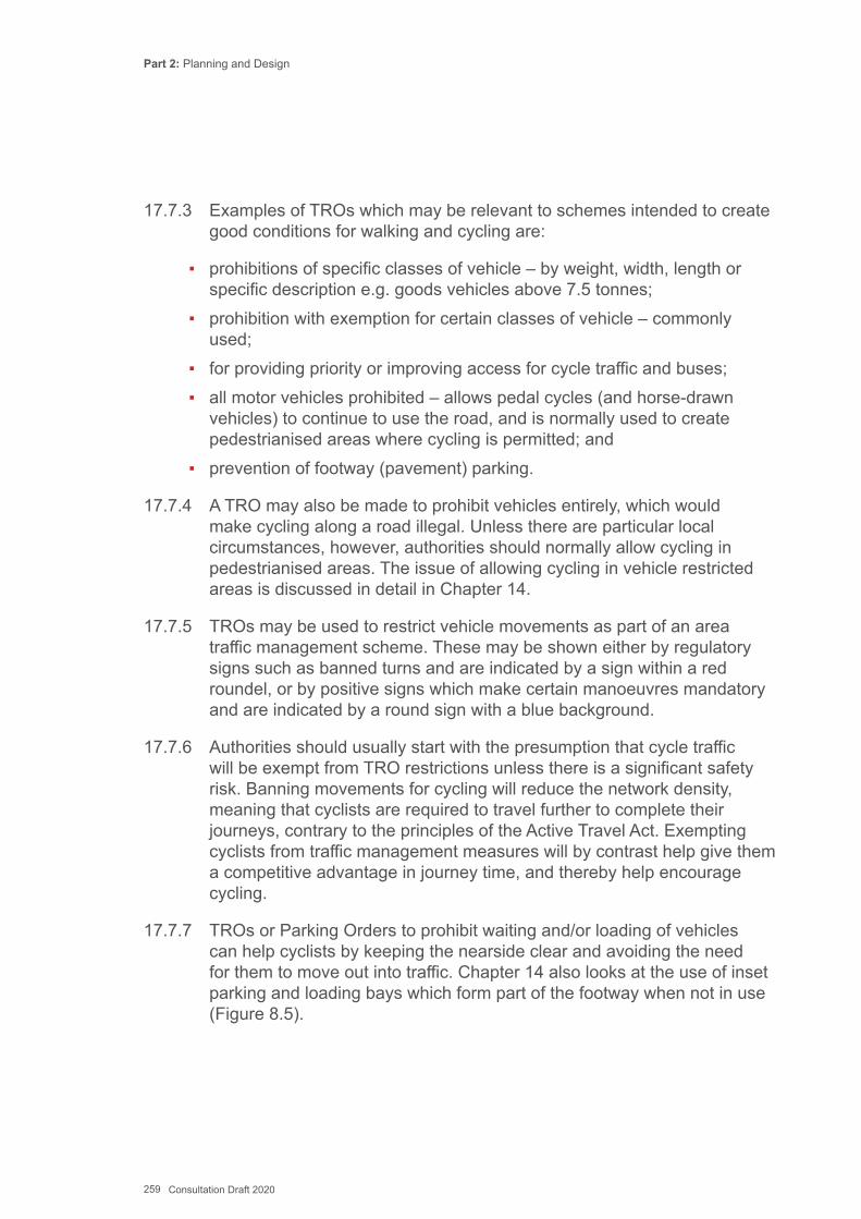
Part 2: Planning and Design
259 Consultation Draft 2020
17.7.3 Examples of TROs which may be relevant to schemes intended to create good conditions for walking and cycling are:
▪ prohibitions of specific classes of vehicle – by weight, width, length or specific description e.g. goods vehicles above 7.5 tonnes;
▪ prohibition with exemption for certain classes of vehicle – commonly used;
▪ for providing priority or improving access for cycle traffic and buses; ▪ all motor vehicles prohibited – allows pedal cycles (and horse-drawn
vehicles) to continue to use the road, and is normally used to create pedestrianised areas where cycling is permitted; and
▪ prevention of footway (pavement) parking.
17.7.4 A TRO may also be made to prohibit vehicles entirely, which would make cycling along a road illegal. Unless there are particular local circumstances, however, authorities should normally allow cycling in pedestrianised areas. The issue of allowing cycling in vehicle restricted areas is discussed in detail in Chapter 14.
17.7.5 TROs may be used to restrict vehicle movements as part of an area traffic management scheme. These may be shown either by regulatory signs such as banned turns and are indicated by a sign within a red roundel, or by positive signs which make certain manoeuvres mandatory and are indicated by a round sign with a blue background.
17.7.6 Authorities should usually start with the presumption that cycle traffic will be exempt from TRO restrictions unless there is a significant safety risk. Banning movements for cycling will reduce the network density, meaning that cyclists are required to travel further to complete their journeys, contrary to the principles of the Active Travel Act. Exempting cyclists from traffic management measures will by contrast help give them a competitive advantage in journey time, and thereby help encourage cycling.
17.7.7 TROs or Parking Orders to prohibit waiting and/or loading of vehicles can help cyclists by keeping the nearside clear and avoiding the need for them to move out into traffic. Chapter 14 also looks at the use of inset parking and loading bays which form part of the footway when not in use (Figure 8.5).
Part 2: Planning and Design
260 Consultation Draft 2020
Figure 8.5: Inset loading bay at footway level
17.7.8 TROs are used to set local speed limits under the guidance contained in Circular 24/2009 ‘Setting Local Speed Limits in Wales’. This guidance states that the needs of vulnerable road users must be fully taken into account to further encourage their mobility and improve their safety. Setting appropriate speed limits has significant benefits for pedestrians and cyclists, and the use of 20mph limits is encouraged and supported by the Welsh Government, particularly in residential areas. The contribution that 20mph limits and zones make to achieving Active Travel Routes is discussed in Chapter 12.
17.7.9 An Experimental Order under chapters 9-13 of the Road Traffic Regulation Act 1984 may be used where there is uncertainty as to the effects or public response to a proposed scheme, or in any other circumstances where a trial measure is considered appropriate.
17.7.10 Trial measures can be particularly useful where there is concern over the effects of reallocating road space on motor traffic capacity and this approach was taken by conning off a traffic lane in Leicester to test the impact of cycle track construction as illustrated in Figure 8.6.
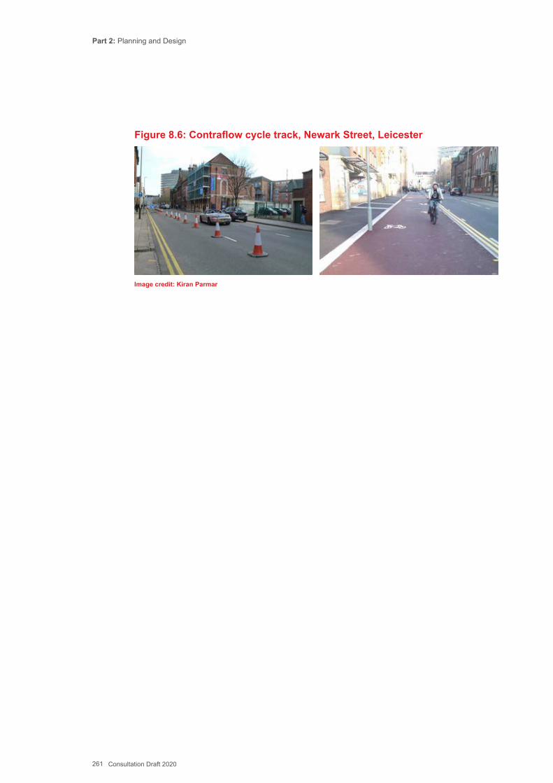
Part 2: Planning and Design
261 Consultation Draft 2020
Figure 8.6: Contraflow cycle track, Newark Street, Leicester
Image credit: Kiran Parmar
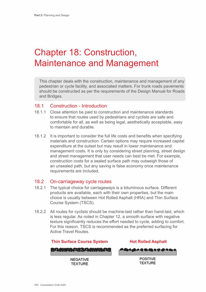
Part 2: Planning and Design
262 Consultation Draft 2020
18.1 Construction - Introduction18.1.1 Close attention be paid to construction and maintenance standards
to ensure that routes used by pedestrians and cyclists are safe and comfortable for all, as well as being legal, aesthetically acceptable, easy to maintain and durable.
18.1.2 It is important to consider the full life costs and benefits when specifying materials and construction. Certain options may require increased capital expenditure at the outset but may result in lower maintenance and management costs. It is only by considering street planning, street design and street management that user needs can best be met. For example, construction costs for a sealed surface path may outweigh those of an unsealed path, but any saving is false economy once maintenance requirements are included.
18.2 On-carriageway cycle routes18.2.1 The typical choice for carriageways is a bituminous surface. Different
products are available, each with their own properties, but the main choice is usually between Hot Rolled Asphalt (HRA) and Thin Surface Course System (TSCS).
18.2.2 All routes for cyclists should be machine-laid rather than hand-laid, which is less regular. As noted in Chapter 12, a smooth surface with negative texture significantly reduces the effort needed to cycle, adding to comfort. For this reason, TSCS is recommended as the preferred surfacing for Active Travel Routes.
Thin Surface Course System Hot Rolled Asphalt
This chapter deals with the construction, maintenance and management of any pedestrian or cycle facility, and associated matters. For trunk roads pavements should be constructed as per the requirements of the Design Manual for Roads and Bridges.
Chapter 18: Construction, Maintenance and Management
Part 2: Planning and Design
263 Consultation Draft 2020
18.2.3 Modifications to the surface may be required to incorporate cycle lanes, advanced stop lines, or traffic speed control measures (traffic calming). Dimensional tolerances should follow normal highway standards.
18.2.4 Where kerb re-alignment is needed any new carriageway construction should be to normal highway standards unless there is kerb segregation of the cycle lane, when a lighter construction should be used, although surface quality should still be to highway standards.
18.3 Coloured surfacing18.3.1 As noted in Chapter 14, black bituminous surfacing in conjunction
with cycle logos and appropriate lane markings is satisfactory in most circumstances and colour should be used sparingly. Extensive use of coloured surfacing is not recommended as it increases maintenance costs. Poorly maintained coloured surfacing can also pose an additional hazard for cyclists.
18.4 Footway construction18.4.1 Footway construction should be of sufficient depth to withstand the loads
likely to be imposed on it.
18.4.2 Consideration should be given to the likelihood of accidental or intentional overrun of a footway by heavy vehicles and the strength/thickness increased accordingly. The construction at vehicle crossovers will need to be thicker than the adjacent lengths of footway. Cracking or rutting of surfaces due to overloading can be unsightly, create trip hazards and/or drainage problems. The construction specification for footways, footpaths and cycle tracks is contained in HD39, Tables 3.1 to 3.4.
18.5 Footpath construction18.5.1 Where a footpath is constructed away from the highway consideration
should be given at the design stage to the practicalities of constructing the path and access arrangements for construction vehicles.
18.5.2 Access points to some paths can be several hundred metres away and may require material to be moved by dumper truck. This might be satisfactory for moving sub-base materials but keeping tarmac hot enough to lay properly may be a concern. Additional access points may need to be constructed, and the path may need to be strong enough to carry heavy plant associated with the works.
Part 2: Planning and Design
264 Consultation Draft 2020
18.5.3 Where a footpath provides regular access for maintenance vehicles e.g. adjacent to waterways or rail lines, the surfacing and construction of the path needs to reflect this.
18.5.4 It may also be necessary to thicken sub base layers, or use geotextile materials where ground conditions are poor. Where paths use land that is contaminated it is best to avoid excavating, use an alternative alignment or raise the path levels if the area cannot be avoided.
18.6 Cycle Track Construction18.6.1 One of the common reasons why some cyclists use the carriageway
in preference to a roadside cycle track is that the ride quality of the carriageway is better. The surface quality of the cycle track should be at least as good as that of the adjacent road and should always be machine laid.
18.6.2 Among the most important considerations in choosing an appropriate surface material are cost (and variation by colour), durability and skid resistance. Polished stone value (PSV) gives a measure of skid resistance. A PSV of 55 is normally acceptable for road skid resistance. Table 9-1 shows, indicatively, a comparison of different surface materials and treatments according to these criteria.
18.6.3 The preferred surface is machine laid bituminous material, although bound or unbound aggregate, concrete or stone flags or paving blocks are sometimes used. Unbound aggregate surfaces are generally unsuitable in an urban/urban fringe environment. They cause excessive dust in dry weather and can be susceptible to ponding and become muddy and in wet weather, leading to rapid deterioration; for these reasons they are not generally recommended.
18.6.4 Paving blocks, concrete or stone flags will provide a more aesthetically attractive finish and are more suited to high quality public realm areas. The surface finish must have adequate skid resistance, the joints will be less comfortable to cycle on and paving can be more problematic to maintain if slabs become loose.
18.6.5 There may be local sensitivities around surfacing of paths with black bituminous material in areas of high heritage value or green spaces. These should be considered and addressed as part of the consultation. If necessary, paths can be surface dressed using appropriate materials such as buff coloured chippings.
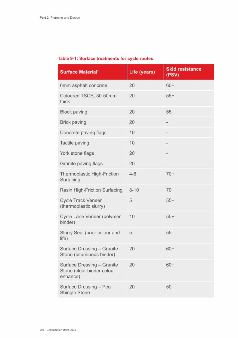
Part 2: Planning and Design
265 Consultation Draft 2020
Table 9-1: Surface treatments for cycle routes
Surface Material1 Life (years) Skid resistance (PSV)
6mm asphalt concrete 20 60+
Coloured TSCS, 30-50mm thick
20 55+
Block paving 20 55
Brick paving 20 -
Concrete paving flags 10 -
Tactile paving 10 -
York stone flags 20 -
Granite paving flags 20 -
Thermoplastic High-Friction Surfacing
4-6 70+
Resin High-Friction Surfacing 8-10 70+
Cycle Track Veneer (thermoplastic slurry)
5 55+
Cycle Lane Veneer (polymer binder)
10 55+
Slurry Seal (poor colour and life)
5 55
Surface Dressing – Granite Stone (bituminous binder)
20 60+
Surface Dressing – Granite Stone (clear binder colour enhance)
20 60+
Surface Dressing – Pea Shingle Stone
20 50
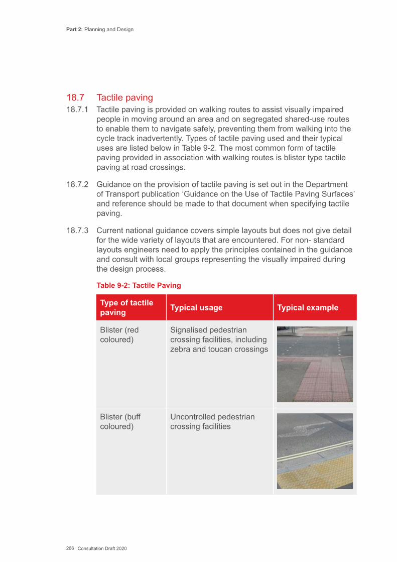
Part 2: Planning and Design
266 Consultation Draft 2020
18.7 Tactile paving18.7.1 Tactile paving is provided on walking routes to assist visually impaired
people in moving around an area and on segregated shared-use routes to enable them to navigate safely, preventing them from walking into the cycle track inadvertently. Types of tactile paving used and their typical uses are listed below in Table 9-2. The most common form of tactile paving provided in association with walking routes is blister type tactile paving at road crossings.
18.7.2 Guidance on the provision of tactile paving is set out in the Department of Transport publication ‘Guidance on the Use of Tactile Paving Surfaces’ and reference should be made to that document when specifying tactile paving.
18.7.3 Current national guidance covers simple layouts but does not give detail for the wide variety of layouts that are encountered. For non- standard layouts engineers need to apply the principles contained in the guidance and consult with local groups representing the visually impaired during the design process.
Table 9-2: Tactile Paving
Type of tactile paving Typical usage Typical example
Blister (red coloured)
Signalised pedestrian crossing facilities, including zebra and toucan crossings
Blister (buff coloured)
Uncontrolled pedestrian crossing facilities

Part 2: Planning and Design
267 Consultation Draft 2020
Type of tactile paving Typical usage Typical example
Corduroy Where a footway joins a shared use path, top and bottom of steps or other hazard
Ladder/tramline Start, end and repeater indication of segregated footway/ cycleway (ladder on footway side and tramline on cycleway side)
18.8 Kerbs, edgings and verges18.8.1 Footways may require some form of edge restraint to maintain their
structural integrity. Where a footway is not adjacent to a wall or building an edging strip is used. Edgings are generally formed from precast concrete units. Any edge treatment will increase the overall cost - pre-cast concrete kerbing roughly doubles the cost of a path. Timber edging may be adequate in rural areas away from the highway, and where the ground is stable.
18.8.2 A kerb is normally used to delineate the carriageway and footway of a road. The kerb offers a degree of protection to pedestrians and can assist blind or partially- sighted pedestrians to identify the edge of the footway.
18.8.3 In lower speed streets and access-only streets it may be appropriate to omit the kerb. In these areas the impact of not providing a kerb on blind or partially-sighted users should be considered with appropriate use of tactile paving (including guidance paving for navigation), or a low kerb upstand be retained. Further guidance on the design of low speed streets is given in Chapter 14. Kerb heights should be as set out in Table 9-3.
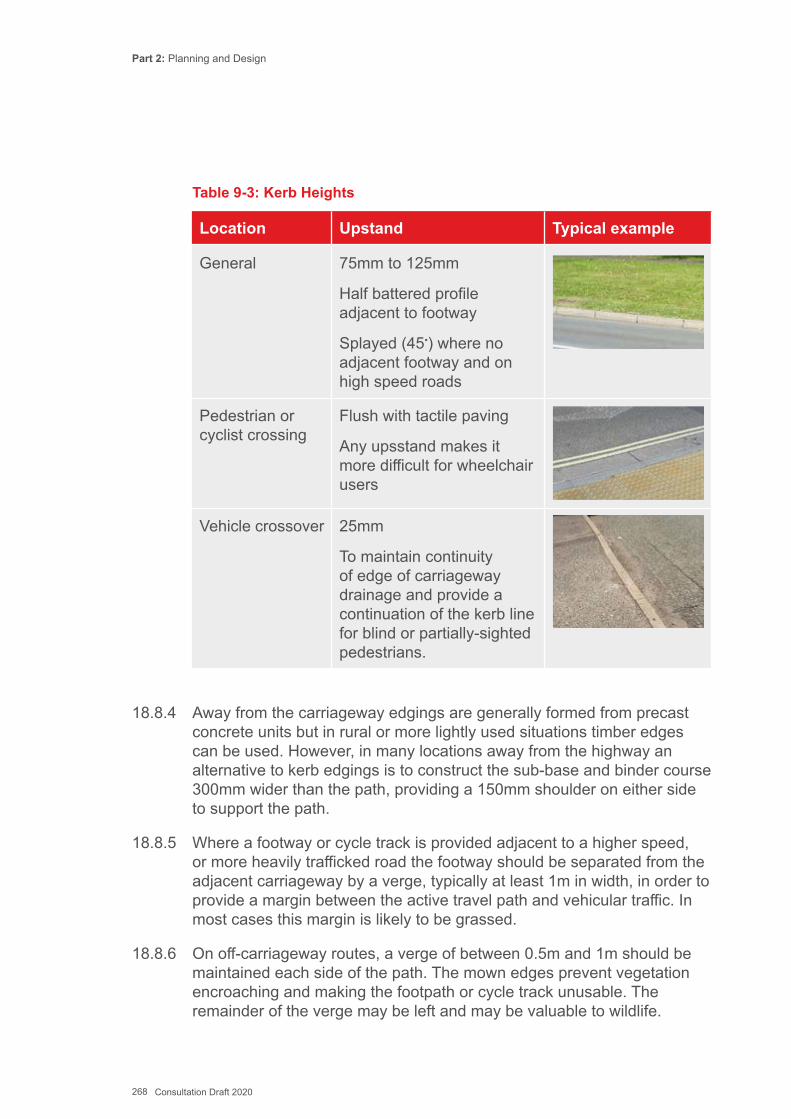
Part 2: Planning and Design
268 Consultation Draft 2020
Table 9-3: Kerb Heights
Location Upstand Typical example
General 75mm to 125mm
Half battered profile adjacent to footway
Splayed (45•) where no adjacent footway and on high speed roads
Pedestrian or cyclist crossing
Flush with tactile paving
Any upsstand makes it more difficult for wheelchair users
Vehicle crossover 25mm
To maintain continuity of edge of carriageway drainage and provide a continuation of the kerb line for blind or partially-sighted pedestrians.
18.8.4 Away from the carriageway edgings are generally formed from precast concrete units but in rural or more lightly used situations timber edges can be used. However, in many locations away from the highway an alternative to kerb edgings is to construct the sub-base and binder course 300mm wider than the path, providing a 150mm shoulder on either side to support the path.
18.8.5 Where a footway or cycle track is provided adjacent to a higher speed, or more heavily trafficked road the footway should be separated from the adjacent carriageway by a verge, typically at least 1m in width, in order to provide a margin between the active travel path and vehicular traffic. In most cases this margin is likely to be grassed.
18.8.6 On off-carriageway routes, a verge of between 0.5m and 1m should be maintained each side of the path. The mown edges prevent vegetation encroaching and making the footpath or cycle track unusable. The remainder of the verge may be left and may be valuable to wildlife.
Part 2: Planning and Design
269 Consultation Draft 2020
18.9 Drainage18.9.1 Standing water and poorly-designed surface water run-off can cause
problems for users and damage pavement construction. Keeping water off and moving it away from a carriageway or path will increase the longevity of the pavement structure and increase its use. Any drainage system needs to be efficient and reliable and may need to extend beyond the immediate edges of a new path to be effective.
18.9.2 Where the water comes from and how it is disposed of needs proper consideration as part of the route design. Poor drainage can lead to safety and maintenance issues. Where practicable, new surfaces should make use of natural SUDS solutions, that can help reduce the pressure on existing urban waste water systems or flooding risks associated with direct discharge to water courses.
18.10 On-Carriageway Drainage18.10.1 On the carriageway, attention will need to be paid to the gully location and
levels, which are critical for cyclists comfort and safety as well as route drainage. This is particularly important where full or light segregation for cycling has been introduced, since cyclists may find it difficult to avoid gullies. Acceptable gully characteristics are as follows:
▪ The grate slots should be at right angles to the direction of travel so that thin cycle wheels do not become trapped in them. Alternatively, non-slot ‘pedestrian style’ gratings should be provided;
▪ The gulley width should be less than a third of the overall cycle lane width;
▪ No gaps between the frame and cover wider than 15 mm; ▪ Recessed gully frames raised to be flush (tolerance +/- 5mm) with the
surrounding surface; ▪ Equipment suitable for their location to take public highway loadings; and ▪ Opened in a manner suitable to be cleansed by a normal gully cleansing
or jetting machine under the local highway authority contract.
18.10.2 Any gratings unsuitable for cycling across should be replaced. Side-entry gullies or perforated kerb type gullies may be suitable in some circumstances, particularly where there is restricted width and where cyclists will be close to the kerb.
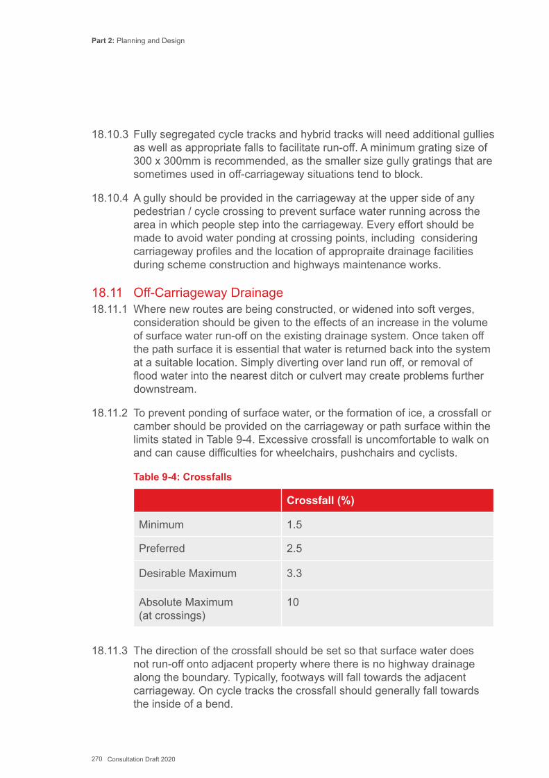
Part 2: Planning and Design
270 Consultation Draft 2020
18.10.3 Fully segregated cycle tracks and hybrid tracks will need additional gullies as well as appropriate falls to facilitate run-off. A minimum grating size of 300 x 300mm is recommended, as the smaller size gully gratings that are sometimes used in off-carriageway situations tend to block.
18.10.4 A gully should be provided in the carriageway at the upper side of any pedestrian / cycle crossing to prevent surface water running across the area in which people step into the carriageway. Every effort should be made to avoid water ponding at crossing points, including considering carriageway profiles and the location of appropraite drainage facilities during scheme construction and highways maintenance works.
18.11 Off-Carriageway Drainage18.11.1 Where new routes are being constructed, or widened into soft verges,
consideration should be given to the effects of an increase in the volume of surface water run-off on the existing drainage system. Once taken off the path surface it is essential that water is returned back into the system at a suitable location. Simply diverting over land run off, or removal of flood water into the nearest ditch or culvert may create problems further downstream.
18.11.2 To prevent ponding of surface water, or the formation of ice, a crossfall or camber should be provided on the carriageway or path surface within the limits stated in Table 9-4. Excessive crossfall is uncomfortable to walk on and can cause difficulties for wheelchairs, pushchairs and cyclists.
Table 9-4: Crossfalls
Crossfall (%)
Minimum 1.5
Preferred 2.5
Desirable Maximum 3.3
Absolute Maximum (at crossings)
10
18.11.3 The direction of the crossfall should be set so that surface water does not run-off onto adjacent property where there is no highway drainage along the boundary. Typically, footways will fall towards the adjacent carriageway. On cycle tracks the crossfall should generally fall towards the inside of a bend.
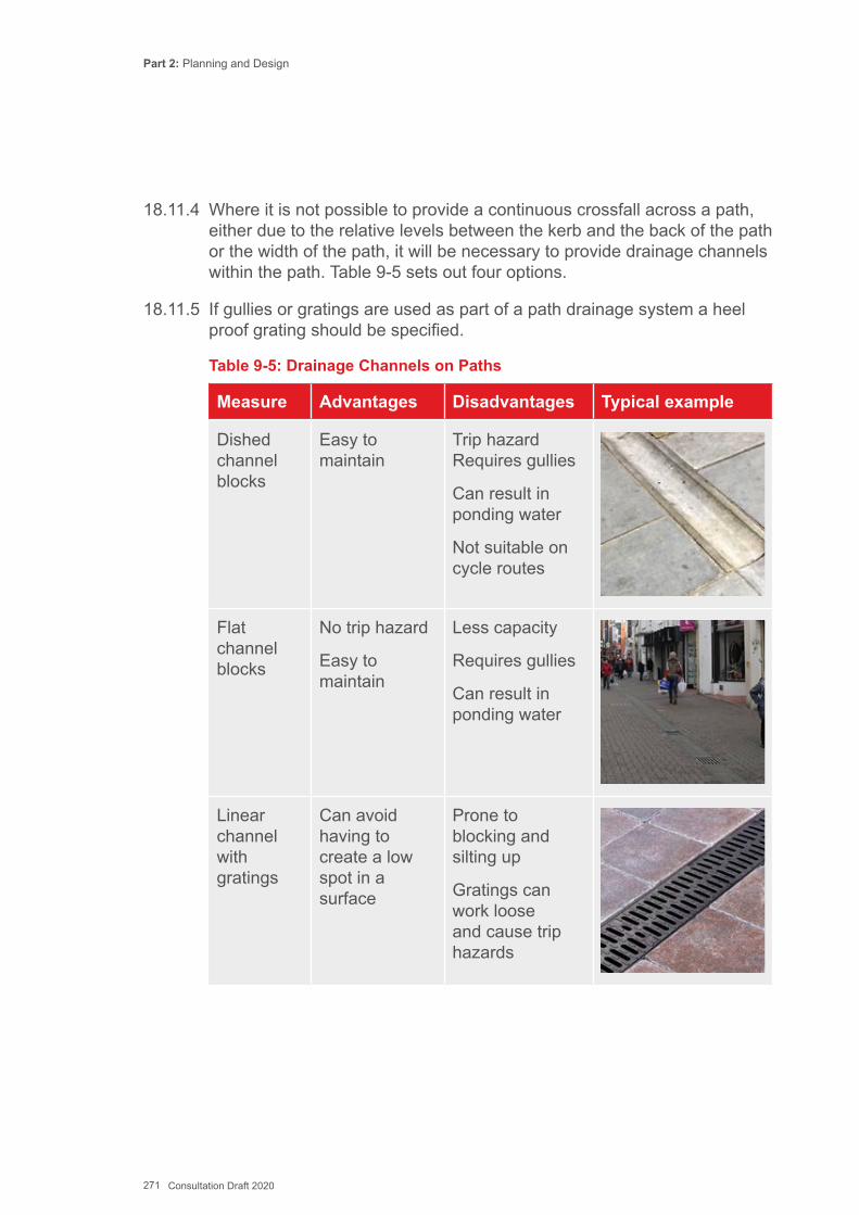
Part 2: Planning and Design
271 Consultation Draft 2020
18.11.4 Where it is not possible to provide a continuous crossfall across a path, either due to the relative levels between the kerb and the back of the path or the width of the path, it will be necessary to provide drainage channels within the path. Table 9-5 sets out four options.
18.11.5 If gullies or gratings are used as part of a path drainage system a heel proof grating should be specified.
Table 9-5: Drainage Channels on Paths
Measure Advantages Disadvantages Typical example
Dished channel blocks
Easy to maintain
Trip hazard Requires gullies
Can result in ponding water
Not suitable on cycle routes
Flat channel blocks
No trip hazard
Easy to maintain
Less capacity
Requires gullies
Can result in ponding water
Linear channel with gratings
Can avoid having to create a low spot in a surface
Prone to blocking and silting up
Gratings can work loose and cause trip hazards

Part 2: Planning and Design
272 Consultation Draft 2020
18.12 Access Controls18.12.1 Access Controls are sometimes placed on off-carriageway routes to
prevent access being gained by unauthorised vehicles, particularly motorcycles.
18.12.2 Designers should start with a presumption against the use of any form of access control, as these cause difficulties to many legitimate users and are often ineffective in addressing the issues they are intended to address. Restrictive access controls:
▪ are inconvenient, can be unsightly and can actively discriminate against some user groups who have legitimate rights to use a path;
▪ extend the journey time for cyclists and so reduce the utility of a cycle route;
▪ add another level of cost, and maintenance concern, to a path; and ▪ are frequently ineffective because fencing along a traffic free corridor is
missing, broken or subsequently vandalised so that the access control can be bypassed.
18.12.3 There is also a tendency to install access barriers to stop, or slow, cyclists at the end of a path for safety reasons – whether actual, or perceived. This is often inappropriate, and designers fail to consider other solutions, such as clear signing and (if necessary) other means of slowing cyclists such as changing path geometry.
18.12.4 A single bollard, and clear sight lines will be effective in many locations. Double rows of bollards, with a minimum spacing of 1.50m can reduce cycle speeds and prevent motor vehicle access, whilst retaining better permeability for users than chicane barriers.
Measure Advantages Disadvantages Typical example
Linear slot drain
Visually un- intrusive
Can have high capacity (in pipe below ground)
Prone to blocking and silting up
Have to be jetted or rodded to be cleaned
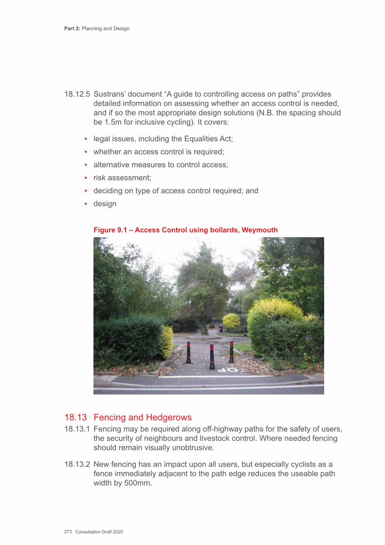
Part 2: Planning and Design
273 Consultation Draft 2020
18.12.5 Sustrans’ document “A guide to controlling access on paths” provides detailed information on assessing whether an access control is needed, and if so the most appropriate design solutions (N.B. the spacing should be 1.5m for inclusive cycling). It covers:
▪ legal issues, including the Equalities Act; ▪ whether an access control is required; ▪ alternative measures to control access; ▪ risk assessment; ▪ deciding on type of access control required; and ▪ design
Figure 9.1 – Access Control using bollards, Weymouth
18.13 Fencing and Hedgerows18.13.1 Fencing may be required along off-highway paths for the safety of users,
the security of neighbours and livestock control. Where needed fencing should remain visually unobtrusive.
18.13.2 New fencing has an impact upon all users, but especially cyclists as a fence immediately adjacent to the path edge reduces the useable path width by 500mm.
Part 2: Planning and Design
274 Consultation Draft 2020
18.13.3 Fences set 1.0m away from a path edge will provide a better visual aspect, and reduce the “tunnel effect” where fences line both sides of a path. Verges provide space for drainage and ducting for lighting.
18.13.4 Security fencing can be harsh and oppressive, creating environments that are visually off putting to pedestrians and cyclists alike. A 1.5m high fence should be adequate in all but exceptional circumstances. To a pedestrian they still provide views over, and the visual and aesthetic impact upon a traffic free route is considerably less than with a taller fence.
18.13.5 Hedgerows form part of the immediate environment for many paths away from or alongside the road. They also provide important habitats for wildlife and connectivity (both visually and for wildlife) to the wider landscape. Developing routes that include at least one hedgerow as a boundary feature can re-invigorate them as dead wood, brambles and unwanted species are removed and new growth encouraged. Thorny species such as Hawthorn or Dog Rose should be avoided where necessary, but if used will require planting further back from the path edge to prevent hedge clippings causing punctures. The design pages on Sustrans website provide further guidance on hedgerows alongside multi-user routes.
18.14 Lighting18.14.1 Walking and cycling must be promoted as around-the-clock means
of transport, rather than just a daylight activity, if they are to play an important role as an alternative to the car for short journeys. Many walking and cycle journeys will be made after dark, especially during the winter months.
18.14.2 Active Travel Routes should normally be lit to provide an adequate level of safety, both real and perceived. It is recognised that some authorities are looking to reduce lighting to reduce costs and light pollution, but the benefits of lighting a walking or cycling route include:
▪ enabling users to orientate themselves and navigate the route ahead; ▪ enabling users to identify other users ahead; ▪ enabling users to detect potential hazards; and ▪ discouraging crime and increasing the sense of personal security.
18.14.3 It is important that the lighting is considered at an early stage in the design process, so that the issues can be properly explored and the needs of users taken fully into account in the choice of equipment and the design of the scheme. Efforts to minimize light pollution and spillage

Part 2: Planning and Design
275 Consultation Draft 2020
in rural areas will be particularly important. In addition, where lighting is proposed in an area previously unlit, the impact on light sensitive species such as bats which are protected by law must be carefully considered.
18.14.4 Routes along urban and many rural highways will be lit by the existing highway lighting but specific lighting will be needed for off-highway routes. However, in lighting such routes consideration also needs to be given to wider factors, including:
▪ limiting levels of light pollution; ▪ level of ambient brightness in the surrounding area; ▪ the visual impact of the lighting equipment; ▪ intrusion on nearby properties; ▪ the needs of visually impaired users for uniform illumination at surface
level; ▪ vandalism issues; ▪ proximity of electricity supply; ▪ energy usage and cost; and ▪ costs of installation, operation and maintenance.
18.15 Maintenance - Introduction18.15.1 Maintaining the path or carriageway surface is of great importance to
pedestrians and cyclists, including proper reinstatement following works by statutory undertakers. It is essential to establish responsibility for maintenance of paths that are not part of the highway and put into place a regular regime for inspections. Having invested time and money to build the route, it is important that it remains attractive to users. A route that is kept in good condition will be more useful and popular than one allowed to deteriorate.
18.15.2 Walking and riding quality should be maintained, particularly keeping routes clean and ice free in autumn and winter.
18.16 Design with maintenance in mind18.16.1 Maintenance should be considered as part of the route development
process long before construction starts. A thoughtful design will mean less maintenance in the future. For example, an off-highway path surfaced with bituminous material will have a long life needing little maintenance.

Part 2: Planning and Design
276 Consultation Draft 2020
18.16.2 The future maintenance burden on local highway authorities, both financial and operational, should be a major consideration for designers and it is recommended that both a Value Engineering and Future Maintenance Audit are carried out on all proposed designs before implementation.
18.16.3 It is particularly important to think about maintenance at the start of the design process if the project has capital funding available, but maintenance will have to come from existing budgets. Sometimes money can be put aside from the capital source into a separate fund for future maintenance. Irrespective of what the arrangement will be, the design team should identify the future maintenance arrangements early in scheme development.
18.17 Maintenance Responsibilities18.17.1 Most active travel routes will be highways under the definition of the
Act (a highway being a route that the public has the right to pass and re-pass), but this does not mean that the highway authority is always responsible for their maintenance. Where the route is on the road it will usually be the responsibility of the highways authority but some routes may well be the responsibility of another part(s) of the council – for example the education authority if the route is through school grounds, or the recreation department for parks and open spaces.
18.17.2 Every department with future responsibility for the maintenance of the route needs to accept those responsibilities at the outset of the project and allow for them in future budgeting.
18.17.3 Many local parks and former railway greenways have local volunteer groups supplementing the staff carrying out the bigger maintenance tasks. They provide a hugely valuable role, ensuring the local community is involved in its local path and promoting its use, as well as keeping the path in good order.
18.18 Maintenance Tasks18.18.1 Each local highway authority will have its own defect intervention criteria
as part of the ‘well maintained highways’ process and established safety inspection regimes based on the hierarchical status and functionality of each asset.
18.18.2 The following list, though not exhaustive, gives some indication on the type of defects that affect walking and cycling network safety and serviceability.
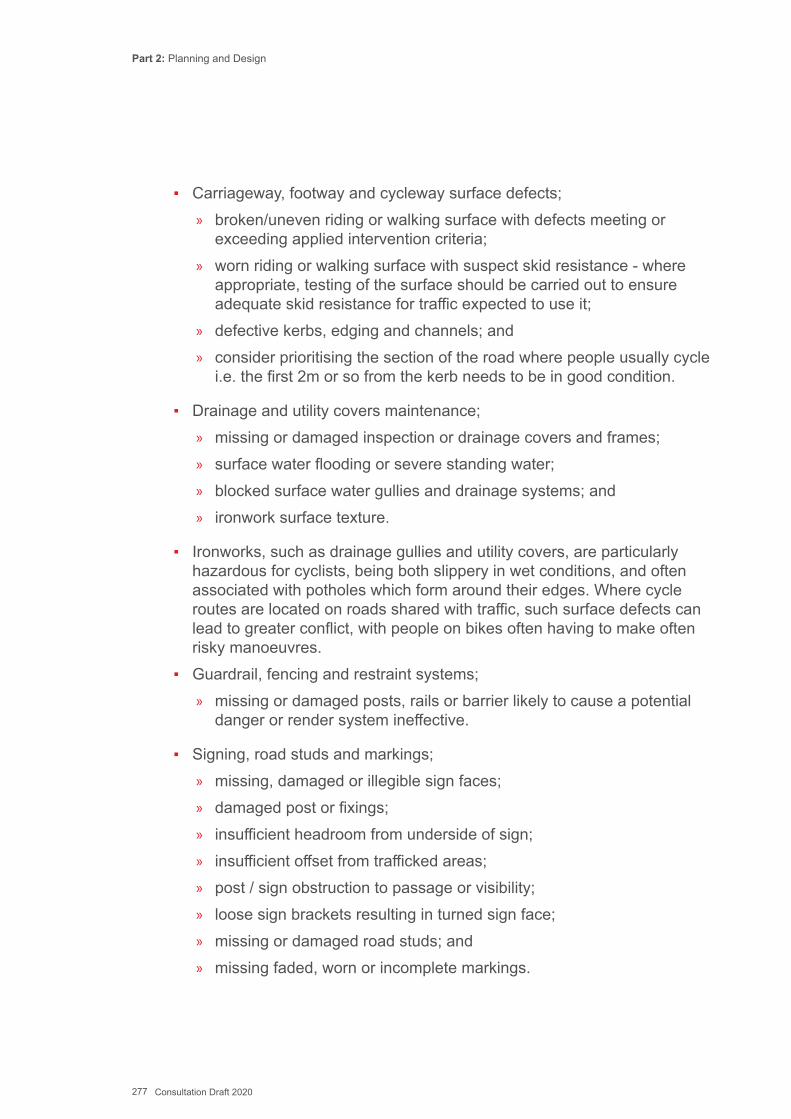
Part 2: Planning and Design
277 Consultation Draft 2020
▪ Carriageway, footway and cycleway surface defects; » broken/uneven riding or walking surface with defects meeting or
exceeding applied intervention criteria; » worn riding or walking surface with suspect skid resistance - where
appropriate, testing of the surface should be carried out to ensure adequate skid resistance for traffic expected to use it;
» defective kerbs, edging and channels; and » consider prioritising the section of the road where people usually cycle
i.e. the first 2m or so from the kerb needs to be in good condition.
▪ Drainage and utility covers maintenance; » missing or damaged inspection or drainage covers and frames; » surface water flooding or severe standing water; » blocked surface water gullies and drainage systems; and » ironwork surface texture.
▪ Ironworks, such as drainage gullies and utility covers, are particularly hazardous for cyclists, being both slippery in wet conditions, and often associated with potholes which form around their edges. Where cycle routes are located on roads shared with traffic, such surface defects can lead to greater conflict, with people on bikes often having to make often risky manoeuvres.
▪ Guardrail, fencing and restraint systems; » missing or damaged posts, rails or barrier likely to cause a potential
danger or render system ineffective.
▪ Signing, road studs and markings; » missing, damaged or illegible sign faces; » damaged post or fixings; » insufficient headroom from underside of sign; » insufficient offset from trafficked areas; » post / sign obstruction to passage or visibility; » loose sign brackets resulting in turned sign face; » missing or damaged road studs; and » missing faded, worn or incomplete markings.
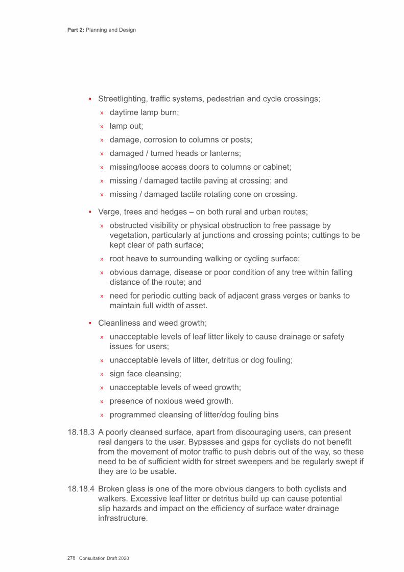
Part 2: Planning and Design
278 Consultation Draft 2020
▪ Streetlighting, traffic systems, pedestrian and cycle crossings; » daytime lamp burn; » lamp out; » damage, corrosion to columns or posts; » damaged / turned heads or lanterns; » missing/loose access doors to columns or cabinet; » missing / damaged tactile paving at crossing; and » missing / damaged tactile rotating cone on crossing.
▪ Verge, trees and hedges – on both rural and urban routes; » obstructed visibility or physical obstruction to free passage by
vegetation, particularly at junctions and crossing points; cuttings to be kept clear of path surface;
» root heave to surrounding walking or cycling surface; » obvious damage, disease or poor condition of any tree within falling
distance of the route; and » need for periodic cutting back of adjacent grass verges or banks to
maintain full width of asset.
▪ Cleanliness and weed growth; » unacceptable levels of leaf litter likely to cause drainage or safety
issues for users; » unacceptable levels of litter, detritus or dog fouling; » sign face cleansing; » unacceptable levels of weed growth; » presence of noxious weed growth. » programmed cleansing of litter/dog fouling bins
18.18.3 A poorly cleansed surface, apart from discouraging users, can present real dangers to the user. Bypasses and gaps for cyclists do not benefit from the movement of motor traffic to push debris out of the way, so these need to be of sufficient width for street sweepers and be regularly swept if they are to be usable.
18.18.4 Broken glass is one of the more obvious dangers to both cyclists and walkers. Excessive leaf litter or detritus build up can cause potential slip hazards and impact on the efficiency of surface water drainage infrastructure.
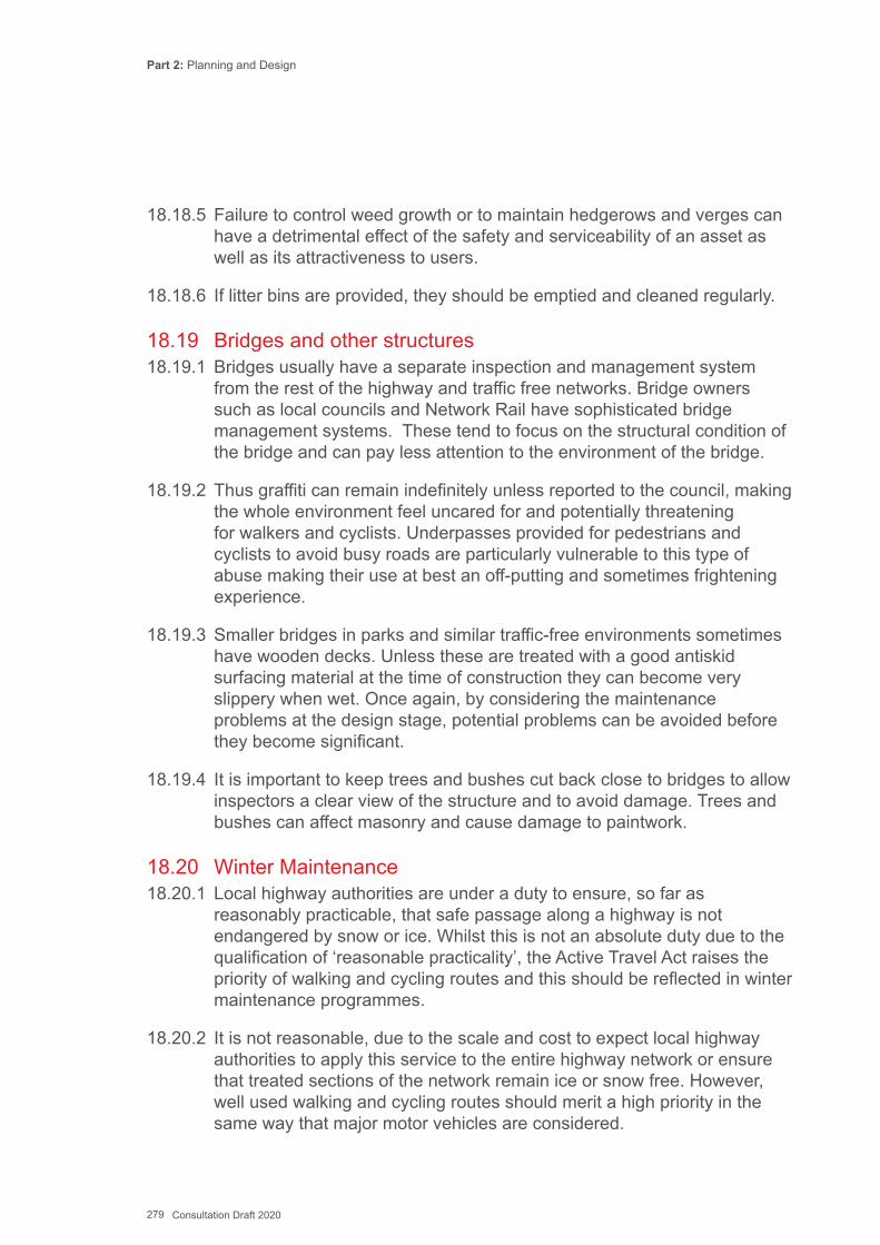
Part 2: Planning and Design
279 Consultation Draft 2020
18.18.5 Failure to control weed growth or to maintain hedgerows and verges can have a detrimental effect of the safety and serviceability of an asset as well as its attractiveness to users.
18.18.6 If litter bins are provided, they should be emptied and cleaned regularly.
18.19 Bridges and other structures18.19.1 Bridges usually have a separate inspection and management system
from the rest of the highway and traffic free networks. Bridge owners such as local councils and Network Rail have sophisticated bridge management systems. These tend to focus on the structural condition of the bridge and can pay less attention to the environment of the bridge.
18.19.2 Thus graffiti can remain indefinitely unless reported to the council, making the whole environment feel uncared for and potentially threatening for walkers and cyclists. Underpasses provided for pedestrians and cyclists to avoid busy roads are particularly vulnerable to this type of abuse making their use at best an off-putting and sometimes frightening experience.
18.19.3 Smaller bridges in parks and similar traffic-free environments sometimes have wooden decks. Unless these are treated with a good antiskid surfacing material at the time of construction they can become very slippery when wet. Once again, by considering the maintenance problems at the design stage, potential problems can be avoided before they become significant.
18.19.4 It is important to keep trees and bushes cut back close to bridges to allow inspectors a clear view of the structure and to avoid damage. Trees and bushes can affect masonry and cause damage to paintwork.
18.20 Winter Maintenance18.20.1 Local highway authorities are under a duty to ensure, so far as
reasonably practicable, that safe passage along a highway is not endangered by snow or ice. Whilst this is not an absolute duty due to the qualification of ‘reasonable practicality’, the Active Travel Act raises the priority of walking and cycling routes and this should be reflected in winter maintenance programmes.
18.20.2 It is not reasonable, due to the scale and cost to expect local highway authorities to apply this service to the entire highway network or ensure that treated sections of the network remain ice or snow free. However, well used walking and cycling routes should merit a high priority in the same way that major motor vehicles are considered.
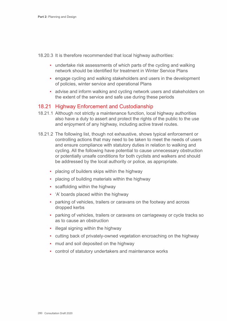
Part 2: Planning and Design
280 Consultation Draft 2020
18.20.3 It is therefore recommended that local highway authorities:
▪ undertake risk assessments of which parts of the cycling and walking network should be identified for treatment in Winter Service Plans
▪ engage cycling and walking stakeholders and users in the development of policies, winter service and operational Plans
▪ advise and inform walking and cycling network users and stakeholders on the extent of the service and safe use during these periods
18.21 Highway Enforcement and Custodianship18.21.1 Although not strictly a maintenance function, local highway authorities
also have a duty to assert and protect the rights of the public to the use and enjoyment of any highway, including active travel routes.
18.21.2 The following list, though not exhaustive, shows typical enforcement or controlling actions that may need to be taken to meet the needs of users and ensure compliance with statutory duties in relation to walking and cycling. All the following have potential to cause unnecessary obstruction or potentially unsafe conditions for both cyclists and walkers and should be addressed by the local authority or police, as appropriate.
▪ placing of builders skips within the highway ▪ placing of building materials within the highway ▪ scaffolding within the highway ▪ ‘A’ boards placed within the highway ▪ parking of vehicles, trailers or caravans on the footway and across
dropped kerbs ▪ parking of vehicles, trailers or caravans on carriageway or cycle tracks so
as to cause an obstruction ▪ illegal signing within the highway ▪ cutting back of privately-owned vegetation encroaching on the highway ▪ mud and soil deposited on the highway ▪ control of statutory undertakers and maintenance works
Part 2: Planning and Design
281 Consultation Draft 2020
Key ReferencesCycling England: Design Guidance, C.06 Maintenance Sustrans (2012) Trees, Technical Information Note 11UK Roads Board (2003) Footway and Cycle Route Design, Construction and Maintenance Guide, Application Guide AG26 (Version 2)Department for Transport (1999) Cyclists at Road Works, TAL 15/99 Sustrans (April 2011) A Guide to Controlling Access on Paths Sustrans (2012) Technical Information Note 12 Lighting of Cycle PathsSustrans Technical Information Notes E 01 “Hedgerow Management” for further guidanceDepartment for Transport, Guidance on the use of tactile paving surfaces Transport for London (2013) Cycling Design StandardsUK Roads Board (2005) Well-maintained Highways - Code of Practice for Highway Maintenance ManagementDepartment for Transport (October 2013) Safety at Street Works and Road Works - A Code of Practice
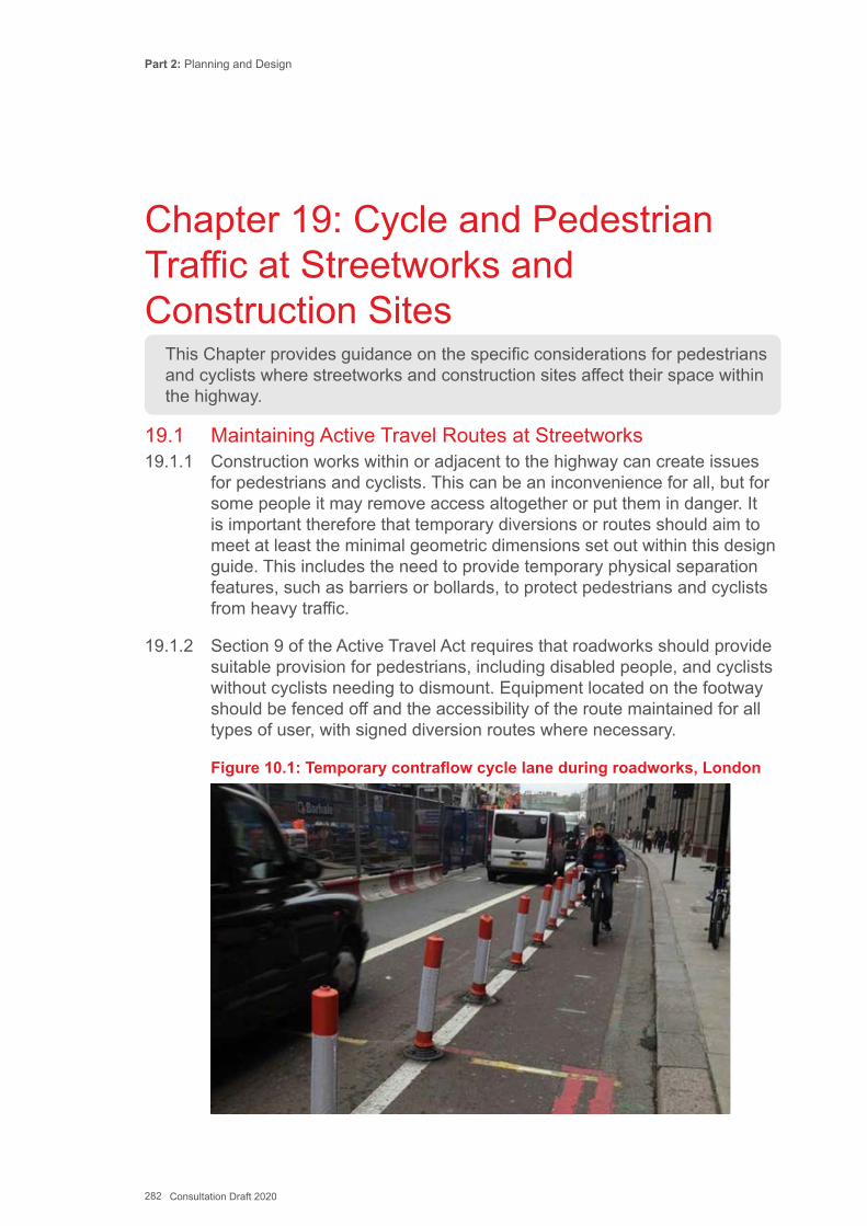
Part 2: Planning and Design
282 Consultation Draft 2020
This Chapter provides guidance on the specific considerations for pedestrians and cyclists where streetworks and construction sites affect their space within the highway.
Chapter 19: Cycle and Pedestrian Traffic at Streetworks and Construction Sites
19.1 Maintaining Active Travel Routes at Streetworks19.1.1 Construction works within or adjacent to the highway can create issues
for pedestrians and cyclists. This can be an inconvenience for all, but for some people it may remove access altogether or put them in danger. It is important therefore that temporary diversions or routes should aim to meet at least the minimal geometric dimensions set out within this design guide. This includes the need to provide temporary physical separation features, such as barriers or bollards, to protect pedestrians and cyclists from heavy traffic.
19.1.2 Section 9 of the Active Travel Act requires that roadworks should provide suitable provision for pedestrians, including disabled people, and cyclists without cyclists needing to dismount. Equipment located on the footway should be fenced off and the accessibility of the route maintained for all types of user, with signed diversion routes where necessary.
Figure 10.1: Temporary contraflow cycle lane during roadworks, London
Part 2: Planning and Design
283 Consultation Draft 2020
19.1.3 UK Department for Transport guidance concerning street works and road works, Safety at Street Works and Road Works - A Code of Practice, states that: “If your work is going to obstruct a footway or part of a footway, you must provide a safe route for pedestrians that should include access to adjacent buildings, property and public areas. This route must consider the needs of those with small children, pushchairs and those with reduced mobility, including visually impaired people and people using wheelchairs or mobility scooters. You should always try to enable pedestrians to remain safely on the footway if at all possible.” (p28 DfT, 2013)
19.1.4 Chapter 8 of the Traffic Signs Manual states that: “O3.14.6 Where there is cycle provision, such as cycle lanes or tracks, efforts should be made to keep these open or to provide an acceptable alternative during the road works. They should not be blocked by signs, debris, plant etc”
19.1.5 Road works and any unavoidable consequential route changes must be clearly signed and promoted. Where route changes are planned the local authority must raise awareness in the local community and at key facilities or destinations served by the route. This must include using local radio, talking newspapers, and informing disability groups.
19.2 Issues for Users19.2.1 There are a number of potential hazards or impacts that must be
considered when designing ‘cycle friendly’ temporary traffic management. These include:
▪ pinch points that ‘squeeze’ cyclists ▪ additional kerbs or crossings for pedestrians ▪ removal or obstruction of existing cycle lanes or tracks ▪ removal or closure of existing crossings ▪ unacceptably long diversion routes ▪ inappropriate use of temporary ‘cyclists dismount’ signs: where a clear
route has been maintained, cyclists should still be able to use the carriageway
▪ poor temporary road/footway surfaces, including raised ironworks ▪ raised cable protectors, hoses or road plates that cause skid/trip hazard ▪ road closures (without cyclist/pedestrian exemption)
Part 2: Planning and Design
284 Consultation Draft 2020
▪ one-way working (without cyclist exemption) ▪ cyclists entering the work site ▪ measures to avoid conflicts between cyclists and other vulnerable road
users
19.2.2 Consideration of these issues should be made from the outset of every project, whether it is a major scheme or minor maintenance.
19.3 Principles for Managing Active Travel at Streetworks19.3.1 Birmingham City Council recently adopted ten principles for cycle routes
that should apply during temporary works. These have been adapted to include pedestrian needs:
1. ENSURE ROUTES MEET THE 5 KEY CRITERIA FOR CYCLE AND PEDESTRIAN INFRASTRUCTURE DESIGN
The 5 key criteria for high quality active travel infrastructure are equally essential to delivering suitable temporary routes. These criteria are: coherent, direct, safe, attractive and comfortable. This includes ensuring that any routes through the works remain navigable by disabled people.
2. PROVIDE SUFFICIENT SPACE FOR THE “DESIGN CYCLE” and PEOPLE USING MOBILITY AIDS
The “Design cycle” and the needs of the users, who may or may not be mobility or sensory impaired, young or old, need to be safely accommodated at all times. Chapter 12 illustrates common cycle styles. The design cycle is 1.20m wide x 2.80m long. Designing for this dimension will also accommodate wheelchairs, double buggies and mobility scooters.
3. MAINTAIN TWO-WAY ACCESS Access for cycle and pedestrian traffic should be maintained in both
directions, even if motor traffic needs to be prohibited. Where motor vehicles are still permitted, provision for cycle traffic to remain on the road should also be provided.
4. AVOID PINCHPOINTS and WALKING IN THE CARRIAGEWAY Avoid traffic lanes between 3.10m and 4.0m wide wherever possible.
A usable two-way cycle track 2.50m wide with 0.50m wide protected barriers can be retained within one standard traffic lane. This may be a more practical solution than a diversion route or shared footway use. It becomes possible if temporary traffic signals / shuttle working are employed for motorised vehicle movements. If shared use is unavoidable
Part 2: Planning and Design
285 Consultation Draft 2020
and it is too narrow for people to cycle safely, an alternative route should be signed for disabled cyclists that are unable to dismount. Pedestrians must not be made to walk in the carriageway without some form of protective temporary fencing or bollards.
5. ALLOW SUFFICIENT TIME THROUGH TEMPORARY SIGNALS and CROSSINGS
Where temporary traffic signals are employed timings should be determined to allow a cycle user to ride through the road works without being “pressured” by motorised vehicles. Where narrow traffic lanes result in cyclists having to join the queue of motorised traffic up to date counts of cycle numbers are recommended so that timings can be adapted to maximise vehicle movements and reduce or manage the impact of queue lengths. Temporary portable pedestrian crossing signals normally operate on a ‘fixed time’ basis and the crossing time should be adjusted to accommodate the slowest pedestrians.
6. RETAIN CROSSING FACILITIES Key crossing points should remain operational at all times, even if
motorised traffic has been excluded. Traffic signals may be switched off where it is appropriate to do so, however this needs to be balanced against any movements for construction traffic. Where key crossing points need to be closed off during works then a suitable alternative should be provided as close to the original as is practicable to do so.
7. ENSURE WIDTH OF SHARED SPACES MEETS EXPECTED DEMAND
Shared paths, or sections of existing footway that need to be used where cycle traffic cannot retain use of the carriageway surface should take into account user numbers, location of hoardings, access to property, interaction around bus stops as well as pedestrian flows.
In busy areas, or where peak flows create equal movement in each direction widths should be increased to accommodate both groups safely and in comfort. Where space limits available width then the minimum acceptable for shared use should not be less than 3.5m
8. PROVIDE CLEAR SIGNING AND INFORMATION Good quality, consistent and regular temporary signing is very important
for temporary routes to give users confidence when using roads they may be unfamiliar with. All changes to route alignments should be communicated in advance of changes to the layouts being made. The use of “map signs” should be considered.

Part 2: Planning and Design
286 Consultation Draft 2020
A two way track for cycles can be reduced to 2.50m where there are limited hoardings.
Routes exclusively for the use of cycle traffic should be clearly signed, be suitably lit and provide a level surface.
9. ENSURE DIVERSION OR ALTERNATIVE ROUTES REMAIN PRACTICAL OPTIONS
Diversion routes for cycle and pedestrian traffic should ideally be as short as possible and may be more direct than diversions for motor traffic. They should ideally avoid routes that cater for HGV, bus or construction traffic. Diversion routes can be created to encourage future alternative corridors for local residents etc, they should consider contraflow cycling, filtered permeability and improving existing off-road path networks.
10. AVOID IMPACTING EXISTING ACTIVE TRAVEL CORRIDORS Traffic diversions are often impossible to avoid, but diverting motorised
traffic onto already existing active travel routes should be avoided if it is possible and practicable to do so. Monitoring displaced traffic can help to evaluate the success of any intervention, and allow learning for future scheme planning.
19.4 Traffic Lane Widths at Roadworks19.4.1 Temporary traffic management measures should always first aim to
design out risk and remove the hazard and consequential need for warning signs. Retaining the cycle track/lane or providing diversion facilities for cycles which offer equivalent level of service is the preferred option. Temporary works should be observed, maintained and monitored, with any risks and issues continuously addressed.
19.4.2 Where cycles must be accommodated within a shared carriageway, maintaining the same level of service may not always be feasible due to width constraints. Where cycles must share space with motor vehicles past the works site, the lane widths require careful consideration. This is because traffic cannot usually leave the lane to overtake due to the presence of cones etc.
19.4.3 Traffic lane widths between 3.5 and 4.0 metres (where there is no dedicated cycle lane) should generally be avoided as they lead to uncomfortably close overtaking of cycles because drivers are uncertain about whether it is safe to pass. This can be particularly hazardous due to uneven surfaces, raised ironworks and ramps that can cause a cyclist to deviate from a straight line. Lane widths of 4.0m between vertical features enable a more comfortable overtaking clearance.
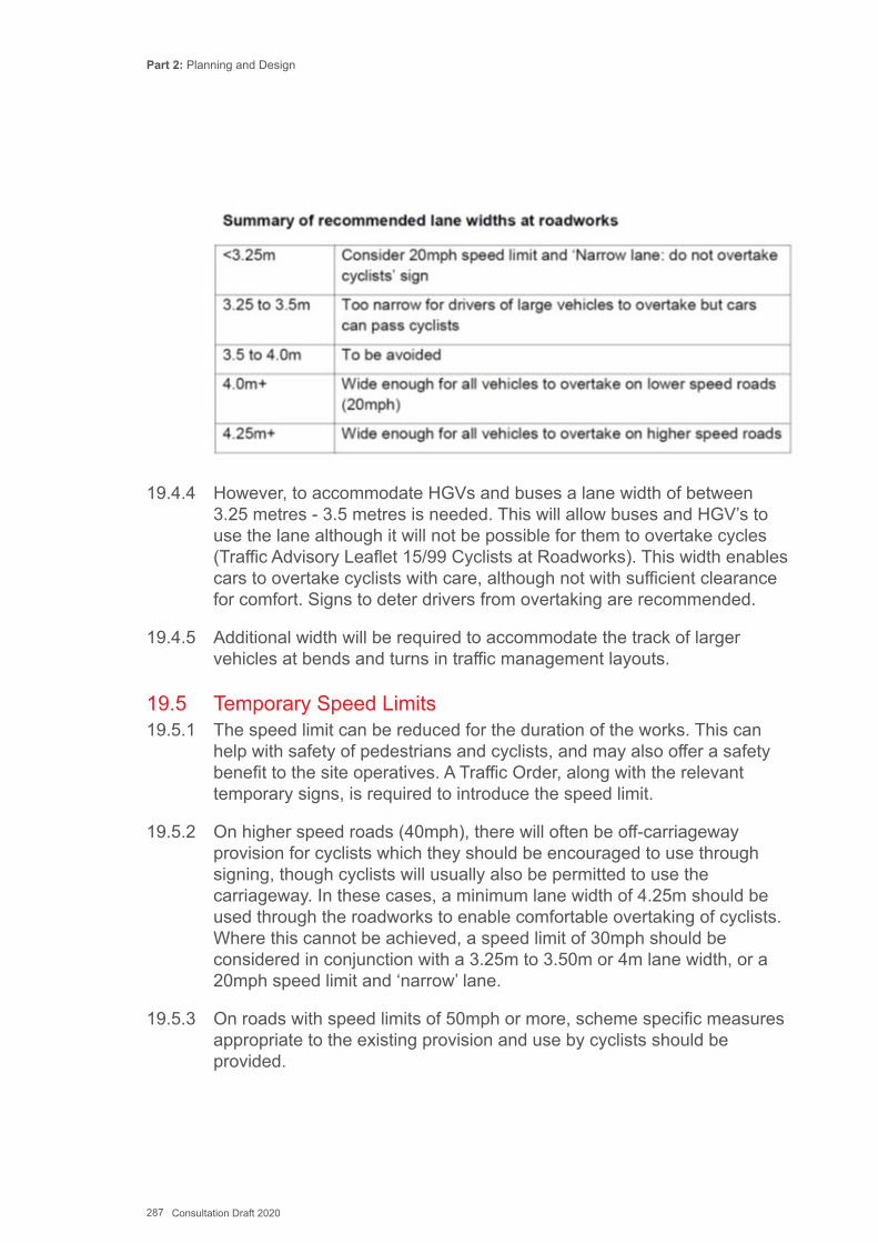
Part 2: Planning and Design
287 Consultation Draft 2020
19.4.4 However, to accommodate HGVs and buses a lane width of between 3.25 metres - 3.5 metres is needed. This will allow buses and HGV’s to use the lane although it will not be possible for them to overtake cycles (Traffic Advisory Leaflet 15/99 Cyclists at Roadworks). This width enables cars to overtake cyclists with care, although not with sufficient clearance for comfort. Signs to deter drivers from overtaking are recommended.
19.4.5 Additional width will be required to accommodate the track of larger vehicles at bends and turns in traffic management layouts.
19.5 Temporary Speed Limits19.5.1 The speed limit can be reduced for the duration of the works. This can
help with safety of pedestrians and cyclists, and may also offer a safety benefit to the site operatives. A Traffic Order, along with the relevant temporary signs, is required to introduce the speed limit.
19.5.2 On higher speed roads (40mph), there will often be off-carriageway provision for cyclists which they should be encouraged to use through signing, though cyclists will usually also be permitted to use the carriageway. In these cases, a minimum lane width of 4.25m should be used through the roadworks to enable comfortable overtaking of cyclists. Where this cannot be achieved, a speed limit of 30mph should be considered in conjunction with a 3.25m to 3.50m or 4m lane width, or a 20mph speed limit and ‘narrow’ lane.
19.5.3 On roads with speed limits of 50mph or more, scheme specific measures appropriate to the existing provision and use by cyclists should be provided.
Part 2: Planning and Design
288 Consultation Draft 2020
This chapter sets out the reasons why local authorities should carry out monitoring and evaluation of active travel routes and schemes and how this should be carried out.
20.1 Introduction20.1.1 Authorities should establish a programme of active travel monitoring,
which will create a baseline for measuring future improvement and progress towards targets and policy goals. The Act requires local authorities to measure changes in levels of use on active travel routes. Monitoring can cover more than just levels of use. For example, local authorities may wish to record changes in the number, severity and type of injury accident at a particular site, or they may wish to record modal share at nearby schools or employers before and after a new route is implemented.
20.1.2 As part of the development of individual improvement schemes, monitoring should be considered from the outset and should be built into projects. The type of monitoring that is undertaken will depend upon factors most relevant to a specific scheme. This chapter explores some of the reasons for monitoring and evaluation and how it can be approached.
20.2 Why Monitor and Evaluate?20.2.1 Gathering data about the usage and impact of routes provides a
justification for existing plans and schemes, helps makes the case for new proposals and with exploring future options. Typically monitoring will be used to:
▪ compare and prioritise scheme design options; ▪ compare active travel schemes with other local transport schemes; ▪ demonstrate that schemes represent value for money; ▪ review operation of an experimental scheme, prior to deciding on whether
to make it permanent; ▪ demonstrate changes in travel behaviour post-implementation; and ▪ assess the operation of innovative schemes to learn lessons on how the
design might be improved in future.
Chapter 20: Monitoring and Evaluation
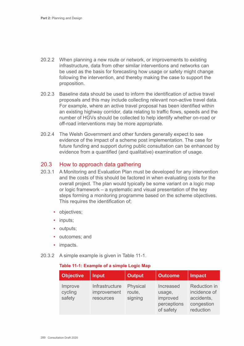
Part 2: Planning and Design
289 Consultation Draft 2020
20.2.2 When planning a new route or network, or improvements to existing infrastructure, data from other similar interventions and networks can be used as the basis for forecasting how usage or safety might change following the intervention, and thereby making the case to support the proposition.
20.2.3 Baseline data should be used to inform the identification of active travel proposals and this may include collecting relevant non-active travel data. For example, where an active travel proposal has been identified within an existing highway corridor, data relating to traffic flows, speeds and the number of HGVs should be collected to help identify whether on-road or off-road interventions may be more appropriate.
20.2.4 The Welsh Government and other funders generally expect to see evidence of the impact of a scheme post implementation. The case for future funding and support during public consultation can be enhanced by evidence from a quantified (and qualitative) examination of usage.
20.3 How to approach data gathering20.3.1 A Monitoring and Evaluation Plan must be developed for any intervention
and the costs of this should be factored in when evaluating costs for the overall project. The plan would typically be some variant on a logic map or logic framework – a systematic and visual presentation of the key steps forming a monitoring programme based on the scheme objectives. This requires the identification of;
▪ objectives; ▪ inputs; ▪ outputs; ▪ outcomes; and ▪ impacts.
20.3.2 A simple example is given in Table 11-1.
Table 11-1: Example of a simple Logic Map
Objective Input Output Outcome Impact
Improve cycling safety
Infrastructure improvement resources
Physical route, signing
Increased usage, improved perceptions of safety
Reduction in incidence of accidents, congestion reduction
Part 2: Planning and Design
290 Consultation Draft 2020
20.3.3 In the context of a route or network intervention the parameters can range widely:
▪ what is the route for? (objectives: increasing commuting, making journeys to school safer);
▪ what might the route achieve? (outcomes: increased tourism activity, increased commuting, improved perceptions of safety); and
▪ what results from the intervention? (impacts: increased tourism revenue, reduced absenteeism, reduction in accidents).
20.3.4 The Monitoring and Evaluation Plan must consider the characteristics of the scheme or network in question. The data to be collected should directly address the intended outcomes and impacts, and should relate to what is on the ground. Is there a suitable location for an automatic counter on the route/ network? Are there schools/ workplaces that are served by the route/ network where data can be gathered?
20.3.5 Consideration should also be given to unintended consequences, such as the possibility that certain users may avoid a route following an intervention. It will not always be easy to ascertain, but good baseline data that identifies the existing level of use by type of user will enable an evaluation of changes in the mix of users.
20.3.6 Cost is a key constraint. The investment in data gathering needs to be proportionate and to address the outcomes and impacts cost effectively. Scaling of costs is not a simple formulaic matter. If a more detailed data set is required, costs are inevitably higher. A low-cost scheme may not necessarily correspond to a scheme with a minimal data requirement. Examples in Sustrans’ portfolio include circumstances where 1% of a £multi-million investment has been spent on monitoring, and others where monitoring has amounted to a quarter of total project cost.
20.4 Data gathering tools 20.4.1 Few local authorities collect much data on walking unless specific to a
scheme, and the collection of data on cycling varies enormously both in consistency and extent. Most monitoring of walking and cycling relates to levels of use, with less attention to patterns of use or user satisfaction.
20.4.2 A wide range of tools for data collection is available. These should be selected according to the information requirements identified to demonstrate the scheme objectives in the Monitoring and Evaluation Plan. Some pertinent data might already be available from existing national or local datasets that could meet the project’s needs before embarking on further data collection.
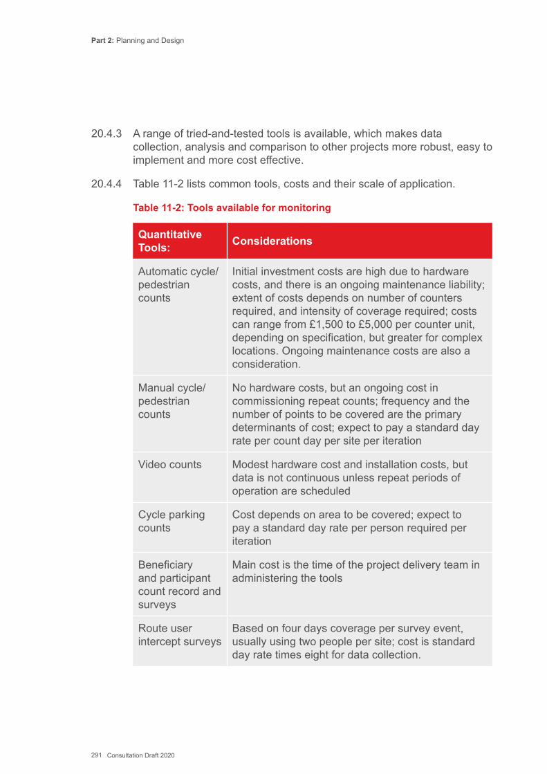
Part 2: Planning and Design
291 Consultation Draft 2020
20.4.3 A range of tried-and-tested tools is available, which makes data collection, analysis and comparison to other projects more robust, easy to implement and more cost effective.
20.4.4 Table 11-2 lists common tools, costs and their scale of application.
Table 11-2: Tools available for monitoring
Quantitative Tools: Considerations
Automatic cycle/ pedestrian counts
Initial investment costs are high due to hardware costs, and there is an ongoing maintenance liability; extent of costs depends on number of counters required, and intensity of coverage required; costs can range from £1,500 to £5,000 per counter unit, depending on specification, but greater for complex locations. Ongoing maintenance costs are also a consideration.
Manual cycle/ pedestrian counts
No hardware costs, but an ongoing cost in commissioning repeat counts; frequency and the number of points to be covered are the primary determinants of cost; expect to pay a standard day rate per count day per site per iteration
Video counts Modest hardware cost and installation costs, but data is not continuous unless repeat periods of operation are scheduled
Cycle parking counts
Cost depends on area to be covered; expect to pay a standard day rate per person required per iteration
Beneficiary and participant count record and surveys
Main cost is the time of the project delivery team in administering the tools
Route user intercept surveys
Based on four days coverage per survey event, usually using two people per site; cost is standard day rate times eight for data collection.

Part 2: Planning and Design
292 Consultation Draft 2020
Quantitative Tools: Considerations
Household travel behaviour survey
Usually very expensive for very strong data; survey design and sampling are part of the process, but the bulk of the cost is surveyor time; key cost determinants are level of coverage with respect to sample size and statistical surety; expect to pay £40,000-90,000 per iteration; typical sample size required would be around 1000 households.
Notes:
1. Surveying participants at events organised by the council or other organisations provides a focused look into the behaviour of individuals who are somehow engaged in active travel initiatives.
2. Process evaluation involves engaging with stakeholders, partners, volunteers and others involved in project delivery to gauge their impressions of how the programme is being carried out.
3. The online intervention diary provides a diary of infrastructure, softer measures (cycle training, events etc) and other factors that might increase activity.
20.5 Recommended Approach20.5.1 Whilst Table 11.2 above provides a range of options and monitoring
techniques that are available to local authorities when developing and delivering active travel schemes, to provide some consistency it is recommended that the following elements are included as part of any Monitoring and Evaluation Plan where relevant:
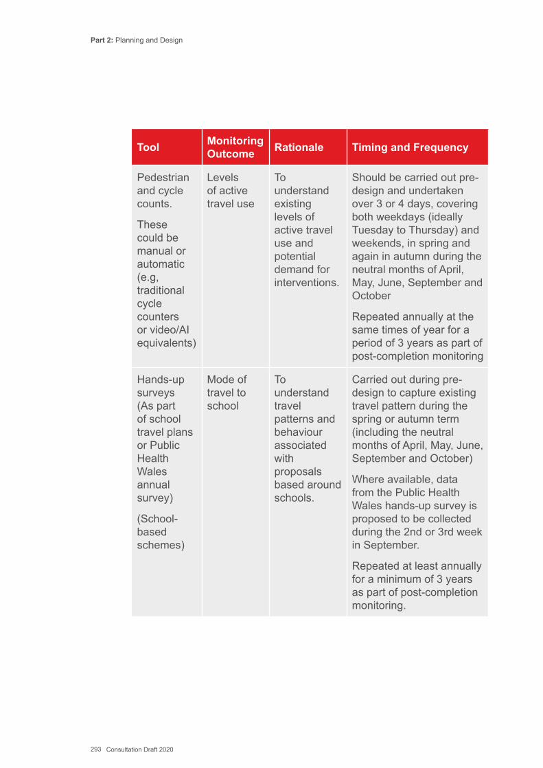
Part 2: Planning and Design
293 Consultation Draft 2020
Tool Monitoring Outcome Rationale Timing and Frequency
Pedestrian and cycle counts.
These could be manual or automatic (e.g, traditional cycle counters or video/AI equivalents)
Levels of active travel use
To understand existing levels of active travel use and potential demand for interventions.
Should be carried out pre-design and undertaken over 3 or 4 days, covering both weekdays (ideally Tuesday to Thursday) and weekends, in spring and again in autumn during the neutral months of April, May, June, September and October
Repeated annually at the same times of year for a period of 3 years as part of post-completion monitoring
Hands-up surveys (As part of school travel plans or Public Health Wales annual survey)
(School-based schemes)
Mode of travel to school
To understand travel patterns and behaviour associated with proposals based around schools.
Carried out during pre-design to capture existing travel pattern during the spring or autumn term (including the neutral months of April, May, June, September and October)
Where available, data from the Public Health Wales hands-up survey is proposed to be collected during the 2nd or 3rd week in September.
Repeated at least annually for a minimum of 3 years as part of post-completion monitoring.
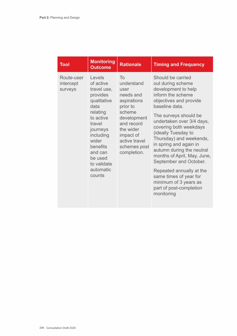
Part 2: Planning and Design
294 Consultation Draft 2020
Tool Monitoring Outcome Rationale Timing and Frequency
Route-user intercept surveys
Levels of active travel use, provides qualitative data relating to active travel journeys including wider benefits and can be used to validate automatic counts
To understand user needs and aspirations prior to scheme development and record the wider impact of active travel schemes post completion.
Should be carried out during scheme development to help inform the scheme objectives and provide baseline data.
The surveys should be undertaken over 3/4 days, covering both weekdays (ideally Tuesday to Thursday) and weekends, in spring and again in autumn during the neutral months of April, May, June, September and October.
Repeated annually at the same times of year for minimum of 3 years as part of post-completion monitoring

Part 2: Planning and Design
295 Consultation Draft 2020
Tool Monitoring Outcome Rationale Timing and Frequency
Traffic surveys
Traffic flows and speeds
(Traffic flows can also be used a proxy measure in relation to air quality in the absence of more accurate air quality data)
To help identify the impact and influence of motorised traffic on route selection and modal choice and to inform options selection alongside use of the audit tools.
Carried out pre-design during both spring and autumn (including the neutral months of April, May, June, September and October) for a minimum of 2 weeks (although ideally for a full calendar month) collecting continuous 24hr data.
However, if scheme development timescales do not permit this, a single count during one of these periods will be considered as acceptable.
Repeated annually at same time of year for minimum of 3 years as part of post-completion monitoring.
Part 2: Planning and Design
296 Consultation Draft 2020
20.5.2 Where schemes connect to educational establishments or large employers, it may also be appropriate to undertake school or workplace travel surveys in addition to the methods identified above. This will allow for the collection of data relating to levels of active travel use and travel behaviour, as well as additional information regarding barriers to active travel and attitudes to health, air quality and the environment.
20.6 Analysing the data20.6.1 The analysis should be planned at the stage of designing the data
collection approach and should be designed to demonstrate progress towards the stated outcome/impact aims of the scheme and consequent output requirements identified in the Monitoring and Evaluation Plan.
20.6.2 Attributing an impact directly to a project or scheme, especially an area-wide intervention, can be complex as other factors are often at work. It is relatively easy to report on the usage of a short stretch of route if counter and user intercept survey data is available. However, this approach can risk significantly underestimating usage on a more complex network due to the failure to account for the parts of the network not covered by data collection activity.
20.6.3 In response to this, anonymous data collection methods such as mobile apps or Bluetooth surveys are being developed that go beyond traditional approaches and provide a variety of data types on the volume and characteristics of journeys at specific points. This data can then be used as a proxy for the usage on the surrounding area. It allows geographically distinct sources of data, collected on a network of routes, to be combined to estimate use across that network. This approach can generate a single annual usage estimate (broken down by user type) for a walking or cycling infrastructure scheme for both pre and post (where data permits) scheme construction.
20.7 Output20.7.1 The output from the analysis will need to be expressed clearly to
communicate the findings to a range of stakeholders and its content and format should be set at the outset in the Monitoring and Evaluation Plan. Chapter 8 of Part 1: Delivery includes the basic requirements of the Act.
20.7.2 Options might include:
Part 2: Planning and Design
297 Consultation Draft 2020
▪ measures of levels of walking and cycling; ▪ measures of / change in;
» levels of walking and cycling; » levels of walking and cycling among particular user groups; » levels of walking and cycling by journey purpose; » perceptions of safety; » perceptions of facets of a route; » revenue-generation performance of a route; » health benefits associated with a route; » economic benefits associated with a route; and
▪ benefit to cost ratio of a route.
20.7.3 Presentation of these results must have regard to the target audiences and be accessible to them. Whilst a detailed analysis may be appropriate for a more technically minded audience, a more visual representation of key results will be more suited to others, including decision makers and the general public.
Key ReferencesTRL (1999) Guidance on Monitoring Local Cycle Use, Report 395 TRL (1999) Research on Monitoring Local Cycle Use, Report 396The Institution of Highways & Transportation (2000) Guidance for Providing for Journeys on Foot
Part 2: Planning and Design
298 Consultation Draft 2020
Glossary Of Common Terms In The Guidance
Active Travel – Journeys on foot or bicycle to access education, employment, entertainment, goods and services. For the purpose of this guidance walking and cycling purely for leisure and sport are excluded from the definition of active travel (although the infrastructure design requirements within urban areas are similar).
Active Travel Network Map – a map which incorporates the Existing Routes Map, with its associated facilities and statements, and the Integrated Network Map required by the Active Travel Act.
Advanced Green – A stage in the traffic signals sequence that allows cyclists to move off a few seconds in advance of other traffic.
Advanced Stop Line (ASL) – Designated waiting area for cyclists at a signalised junction.
Advisory Cycle Lane (ACL) – Cycle lane marked with broken white line.
Bridleway – A right of way for people on horseback, cycles or foot only.
Bus Lane – Lane for buses and cycles only (cycles may be excluded by a traffic order but the default is to permit them)
Cycle – Defined in this guidance as any human powered machine including bicycles, tricycles, tandems, quadricycles and hand-cranked cycles.
Cyclist – For the purpose of this guidance includes anybody using some form of cycle to travel.
Existing Routes Map – Shows the existing routes that are suitable and appropriate for making active travel journeys. Its purpose is to communicate to the public where routes are already available and suitable for active travel.
Footpath – A public right of way (or permissive right of way granted by landowner) for pedestrians only.
Footway – The path for pedestrians alongside the carriageway of a road (cyclists may be permitted to share this if the appropriate signs and markings are present to indicate that this is legal).
Part 2: Planning and Design
299 Consultation Draft 2020
Integrated Network Map – Shows proposed improvements to existing infrastructure and proposed new routes for active travel.
Low level signals – Small traffic signals for cyclists mounted at a lower height than standard traffic lights
Mandatory Cycle Lane (MCL) – Cycle lane marked with continuous white line, other classes of vehicle prohibited.
Mobility Impaired – For the purposes of this guidance includes all people with a disability that makes unassisted walking difficult or impossible. This may include temporary impairments such as carrying heavy luggage or pushchairs.
Parallel Crossing – A zebra crossing for pedestrians with a parallel cycle track crossing marked alongside.
Pedestrian – For the purpose of this guidance includes all people travelling by walking, in wheelchairs and in mobility scooters.
Pegasus Crossing – A signalised crossing for horse riders and cyclists (may or may not have a parallel pedestrian crossing)
Puffin Crossing – A signalised crossing for pedestrians
Sensory Impaired – Includes all people with sensory conditions that make active travel more challenging, including sight loss, hearing loss and learning disabilities.
Toucan Crossing – A signalised crossing shared by pedestrians and cyclists.
Zebra Crossing – A crossing for pedestrians marked by stripes and flashing amber beacons

Part 2: Planning and Design
300 Consultation Draft 2020
Appendices
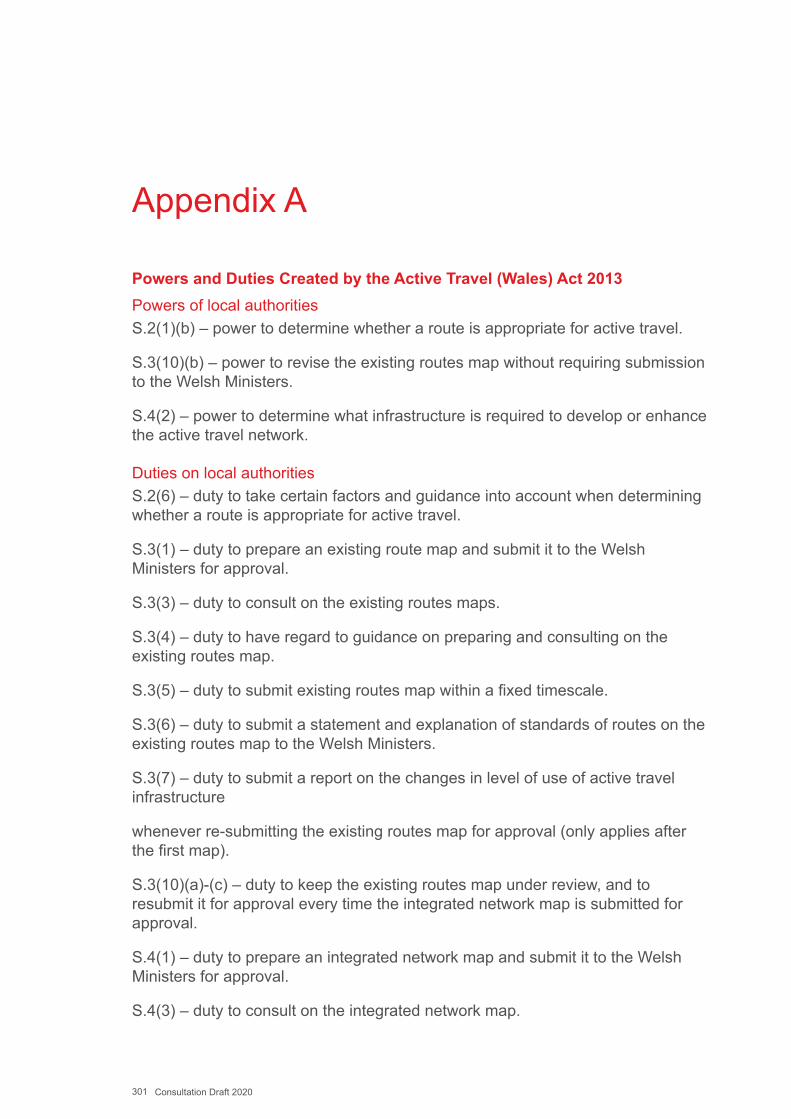
301 Consultation Draft 2020
Appendix A
Powers and Duties Created by the Active Travel (Wales) Act 2013Powers of local authoritiesS.2(1)(b) – power to determine whether a route is appropriate for active travel.
S.3(10)(b) – power to revise the existing routes map without requiring submission to the Welsh Ministers.
S.4(2) – power to determine what infrastructure is required to develop or enhance the active travel network.
Duties on local authoritiesS.2(6) – duty to take certain factors and guidance into account when determining whether a route is appropriate for active travel.
S.3(1) – duty to prepare an existing route map and submit it to the Welsh Ministers for approval.
S.3(3) – duty to consult on the existing routes maps.
S.3(4) – duty to have regard to guidance on preparing and consulting on the existing routes map.
S.3(5) – duty to submit existing routes map within a fixed timescale.
S.3(6) – duty to submit a statement and explanation of standards of routes on the existing routes map to the Welsh Ministers.
S.3(7) – duty to submit a report on the changes in level of use of active travel infrastructure
whenever re-submitting the existing routes map for approval (only applies after the first map).
S.3(10)(a)-(c) – duty to keep the existing routes map under review, and to resubmit it for approval every time the integrated network map is submitted for approval.
S.4(1) – duty to prepare an integrated network map and submit it to the Welsh Ministers for approval.
S.4(3) – duty to consult on the integrated network map.
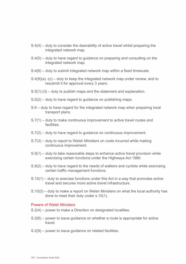
302 Consultation Draft 2020
S.4(4) – duty to consider the desirability of active travel whilst preparing the integrated network map.
S.4(5) – duty to have regard to guidance on preparing and consulting on the integrated network map.
S.4(6) – duty to submit integrated network map within a fixed timescale.
S.4(9)(a) -(c) – duty to keep the integrated network map under review, and to resubmit it for approval every 3 years.
S.5(1)-(3) – duty to publish maps and the statement and explanation.
S.5(2) – duty to have regard to guidance on publishing maps.
S.6 – duty to have regard for the integrated network map when preparing local transport plans.
S.7(1) – duty to make continuous improvement to active travel routes and facilities.
S.7(2) – duty to have regard to guidance on continuous improvement.
S.7(3) – duty to report to Welsh Ministers on costs incurred while making continuous improvement.
S.9(1) – duty to take reasonable steps to enhance active travel provision while exercising certain functions under the Highways Act 1980.
S.9(2) – duty to have regard to the needs of walkers and cyclists while exercising certain traffic management functions.
S.10(1) – duty to exercise functions under this Act in a way that promotes active travel and secures more active travel infrastructure.
S.10(2) – duty to make a report on Welsh Ministers on what the local authority has done to meet their duty under s.10(1).
Powers of Welsh MinistersS.2(4) – power to make a Direction on designated localities.
S.2(6) – power to issue guidance on whether a route is appropriate for active travel.
S.2(9) – power to issue guidance on related facilities.
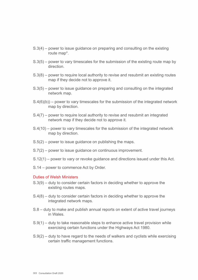
303 Consultation Draft 2020
S.3(4) – power to issue guidance on preparing and consulting on the existing route map*.
S.3(5) – power to vary timescales for the submission of the existing route map by direction.
S.3(8) – power to require local authority to revise and resubmit an existing routes map if they decide not to approve it.
S.3(5) – power to issue guidance on preparing and consulting on the integrated network map.
S.4(6)(b)) – power to vary timescales for the submission of the integrated network map by direction.
S.4(7) – power to require local authority to revise and resubmit an integrated network map if they decide not to approve it.
S.4(10) – power to vary timescales for the submission of the integrated network map by direction.
S.5(2) – power to issue guidance on publishing the maps.
S.7(2) – power to issue guidance on continuous improvement.
S.12(1) – power to vary or revoke guidance and directions issued under this Act.
S.14 – power to commence Act by Order.
Duties of Welsh MinistersS.3(9) – duty to consider certain factors in deciding whether to approve the
existing routes maps.
S.4(8) – duty to consider certain factors in deciding whether to approve the integrated network maps.
S.8 – duty to make and publish annual reports on extent of active travel journeys in Wales.
S.9(1) – duty to take reasonable steps to enhance active travel provision while exercising certain functions under the Highways Act 1980.
S.9(2) – duty to have regard to the needs of walkers and cyclists while exercising certain traffic management functions.

304 Consultation Draft 2020
S.10(1) – duty to exercise functions under this Act in a way that promotes active travel and secures more active travel infrastructure.
S.11 – duty to make full review of the Act 5 years after the publication of the first integrated network map.
S.12(2) – duty to have regard to the desirability of active travel when varying or revoking direction and guidance.
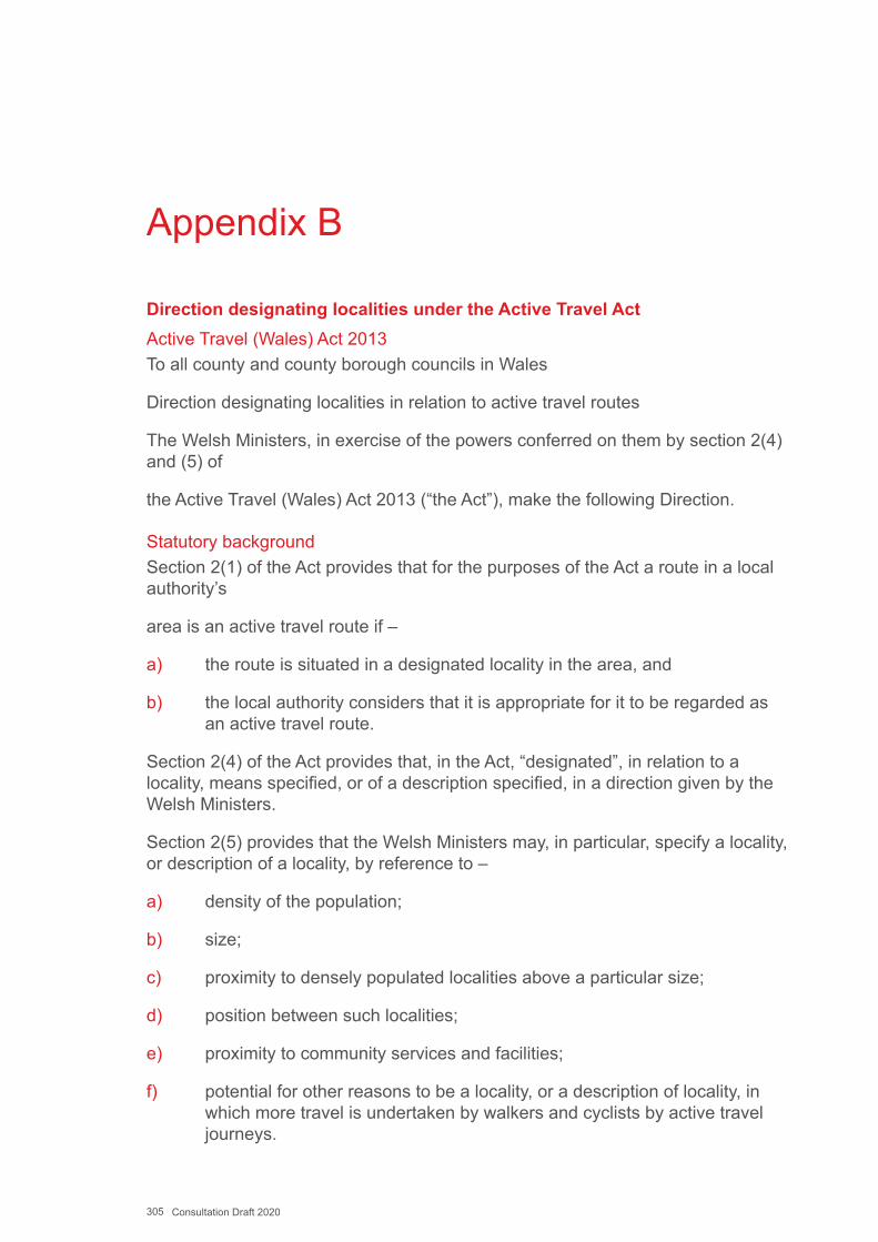
305 Consultation Draft 2020
Appendix B
Direction designating localities under the Active Travel ActActive Travel (Wales) Act 2013To all county and county borough councils in Wales
Direction designating localities in relation to active travel routes
The Welsh Ministers, in exercise of the powers conferred on them by section 2(4) and (5) of
the Active Travel (Wales) Act 2013 (“the Act”), make the following Direction.
Statutory backgroundSection 2(1) of the Act provides that for the purposes of the Act a route in a local authority’s
area is an active travel route if –
a) the route is situated in a designated locality in the area, and
b) the local authority considers that it is appropriate for it to be regarded as an active travel route.
Section 2(4) of the Act provides that, in the Act, “designated”, in relation to a locality, means specified, or of a description specified, in a direction given by the Welsh Ministers.
Section 2(5) provides that the Welsh Ministers may, in particular, specify a locality, or description of a locality, by reference to –
a) density of the population;
b) size;
c) proximity to densely populated localities above a particular size;
d) position between such localities;
e) proximity to community services and facilities;
f) potential for other reasons to be a locality, or a description of locality, in which more travel is undertaken by walkers and cyclists by active travel journeys.
306 Consultation Draft 2020
The DirectionIn exercise of the above powers under the Act, the Welsh Ministers direct that the designatedlocalities for the purposes of the Act are those localities within Wales specified in the Schedulebelow under the heading ‘Designated locality’ The localities are more particularly delineatedon the map with reference:
www.maps.google.com/gallery/details?id=z_Jq-ochhCD4.kxSuDhUrEQTU&hl=en-GB
accompanying this Direction. For ease of reference, the table below sets out which cities, towns and villages are included in the designated locality (where the designated locality covers multiple settlements), the population of the designated locality, and the local authorities with responsibility for that designated locality. Shaded blue indicates that the designated localities run across local authority boundaries, shaded yellow means they fall within a single local authority area.
The designated localities are derived from the Office for National Statistics’ Built Up Areas. The Built-Up Areas are identified by splitting Wales into 50 metre by 50 metre squares. The predominant land use in each square is identified as either built up or not built up (containing buildings and similar infrastructure, or empty of development). Where built up squares sit next to each other, then they are amalgamated into larger built up areas.
If settlements are within 200 metres of each other, then they were linked together into a single ‘Built Up Area’. Many of these Built Up Areas are amalgamations of a number of towns and villages, which are in close proximity to each other and/or to a larger densely populated area. This approach reflects the actual pattern of development, rather than the administrative boundary divisions between settlements.
The designated localities have been named with reference to the largest town or city within the locality, but many stretch beyond the administrative boundaries of that named town or city. Where the shaded areas on the map extend beyond the administrative boundaries of the named town or city, local authorities should follow the boundaries shaded on the map.
Local authorities are not required to map areas in England adjacent to their boundaries.
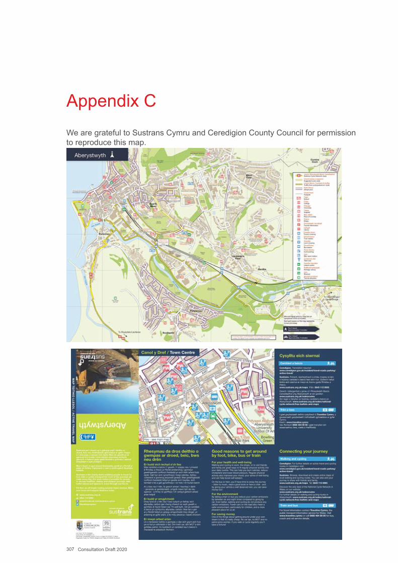
307 Consultation Draft 2020
Appendix CWe are grateful to Sustrans Cymru and Ceredigion County Council for permission to reproduce this map.

308 Consultation Draft 2020
Appendix DModel Engagement ReportThis report must be submitted to Welsh Government with the authority’s draft ATNM.
An electronic version of the report can be downloaded from:
In total, how many engagement events did you organise?
How many people attended?
How were the events advertised?
Have you established a group with which you engage in regular discussion on active travel issues including network planning? If yes, please give a brief description.
Engagement with specific categories of the populationFor each category please give a brief description of how the engagement took place how many people were involved, the names of organisations involved and at which stage of the process the engagement occurred (e.g. regular, ongoing engagement; pre-draft ATNM; formal consultation period).
Category engaged with
No. of people engaged
Organisations involved
Stage of the process
People who do not currently travel actively
Description of the engagement

309 Consultation Draft 2020
Category engaged with
No. of people engaged
Organisations involved
Stage of the process
People with protected characteristics and their organisations
Description of the engagement
People with visual impairments and their organisations
Description of the engagement
Other local authority departments and adjoining local authorities
Description of the engagement
Young People (including school students)
Description of the engagement

310 Consultation Draft 2020
Category engaged with
No. of people engaged
Organisations involved
Stage of the process
People who had requested that they be consulted
Description of the engagement
Walking and cycling organisations
Description of the engagement
Town and Community Councils (where present)
Description of the engagement
Other public bodies, including health organisations
Description of the engagement

311 Consultation Draft 2020
Category engaged with
No. of people engaged
Organisations involved
Stage of the process
Elected members
Description of the engagement
Others (e.g. large employers or other stakeholders)
Description of the engagement
Name of Local Authority:
Contact official: Date Submitted:
Note: Consultation on the Map does not negate any statutory requirements for consultation and engagement that may be required as part of an individual scheme (See Planning and Design Guidance).

312 Consultation Draft 2020
Appendix EThis plan produced by Denbighshire Council shows a draft map of a designated settlement that was accepted by Welsh Government in the first round of submissions.
Please note that, in accordance with Chapter 14 in this guidance, by the third round of map submissions the mesh density of cycling and primary walking routes in designated settlements should be approximately 250 metres.
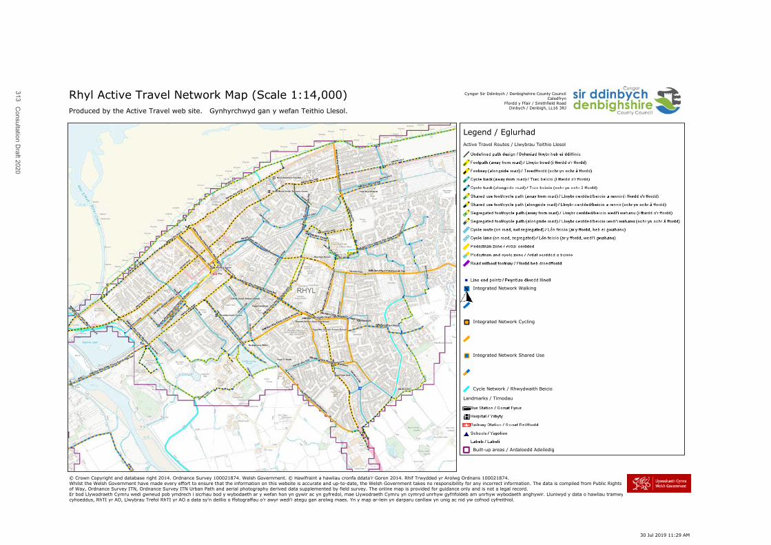
313C
onsultation Draft 2020
Rhyl Active Travel Network Map (Scale 1:14,000)Produced by the Active Travel web site. Gynhyrchwyd gan y wefan Teithio Llesol.
© Crown Copyright and database right 2014. Ordnance Survey 100021874. Welsh Government. © Hawlfraint a hawliau cronfa ddata’r Goron 2014. Rhif Trwydded yr Arolwg Ordnans 100021874.Whilst the Welsh Government have made every effort to ensure that the information on this website is accurate and up-to-date, the Welsh Government takes no responsibility for any incorrect information. The data is compiled from Public Rights of Way, Ordnance Survey ITN, Ordnance Survey ITN Urban Path and aerial photography derived data supplemented by field survey. The online map is provided for guidance only and is not a legal record.Er bod Llywodraeth Cymru wedi gwneud pob ymdrech i sicrhau bod y wybodaeth ar y wefan hon yn gywir ac yn gyfredol, mae Llywodraeth Cymru yn cymryd unrhyw gyfrifoldeb am unrhyw wybodaeth anghywir. Lluniwyd y data o hawliau tramwy cyhoeddus, RhTI yr AO, Llwybrau Trefol RhTI yr AO a data sy'n deillio o ffotograffau o'r awyr wedi'i ategu gan arolwg maes. Yn y map ar-lein yn darparu canllaw yn unig ac nid yw cofnod cyfreithiol.
Cyngor Sir Ddinbych / Denbighshire County CouncilCaledfryn
Ffordd y Ffair / Smithfield RoadDinbych / Denbigh, LL16 3RJ
Legend / EglurhadActive Travel Routes / Llwybrau Teithio Llesol
Integrated Network Walking
Integrated Network Cycling
Integrated Network Shared Use
Cycle Network / Rhwydwaith Beicio
Landmarks / Tirnodau
Built-up areas / Ardaloedd Adeiledig
30 Jul 2019 11:29 AM
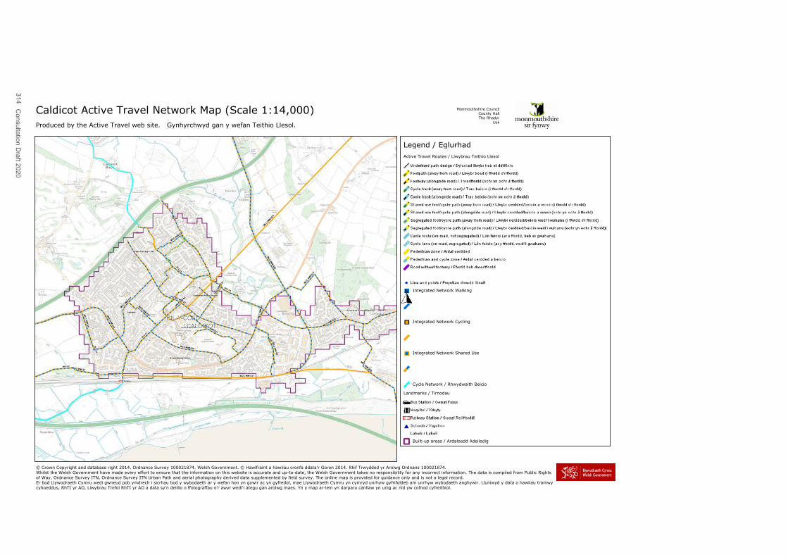
314C
onsultation Draft 2020
Caldicot Active Travel Network Map (Scale 1:14,000)Produced by the Active Travel web site. Gynhyrchwyd gan y wefan Teithio Llesol.
© Crown Copyright and database right 2014. Ordnance Survey 100021874. Welsh Government. © Hawlfraint a hawliau cronfa ddata’r Goron 2014. Rhif Trwydded yr Arolwg Ordnans 100021874.Whilst the Welsh Government have made every effort to ensure that the information on this website is accurate and up-to-date, the Welsh Government takes no responsibility for any incorrect information. The data is compiled from Public Rights of Way, Ordnance Survey ITN, Ordnance Survey ITN Urban Path and aerial photography derived data supplemented by field survey. The online map is provided for guidance only and is not a legal record.Er bod Llywodraeth Cymru wedi gwneud pob ymdrech i sicrhau bod y wybodaeth ar y wefan hon yn gywir ac yn gyfredol, mae Llywodraeth Cymru yn cymryd unrhyw gyfrifoldeb am unrhyw wybodaeth anghywir. Lluniwyd y data o hawliau tramwy cyhoeddus, RhTI yr AO, Llwybrau Trefol RhTI yr AO a data sy'n deillio o ffotograffau o'r awyr wedi'i ategu gan arolwg maes. Yn y map ar-lein yn darparu canllaw yn unig ac nid yw cofnod cyfreithiol.
Monmouthshire CouncilCounty HallThe Rhadyr
Usk
Legend / EglurhadActive Travel Routes / Llwybrau Teithio Llesol
Integrated Network Walking
Integrated Network Cycling
Integrated Network Shared Use
Cycle Network / Rhwydwaith Beicio
Landmarks / Tirnodau
Built-up areas / Ardaloedd Adeiledig
30 Jul 2019 11:03 AM
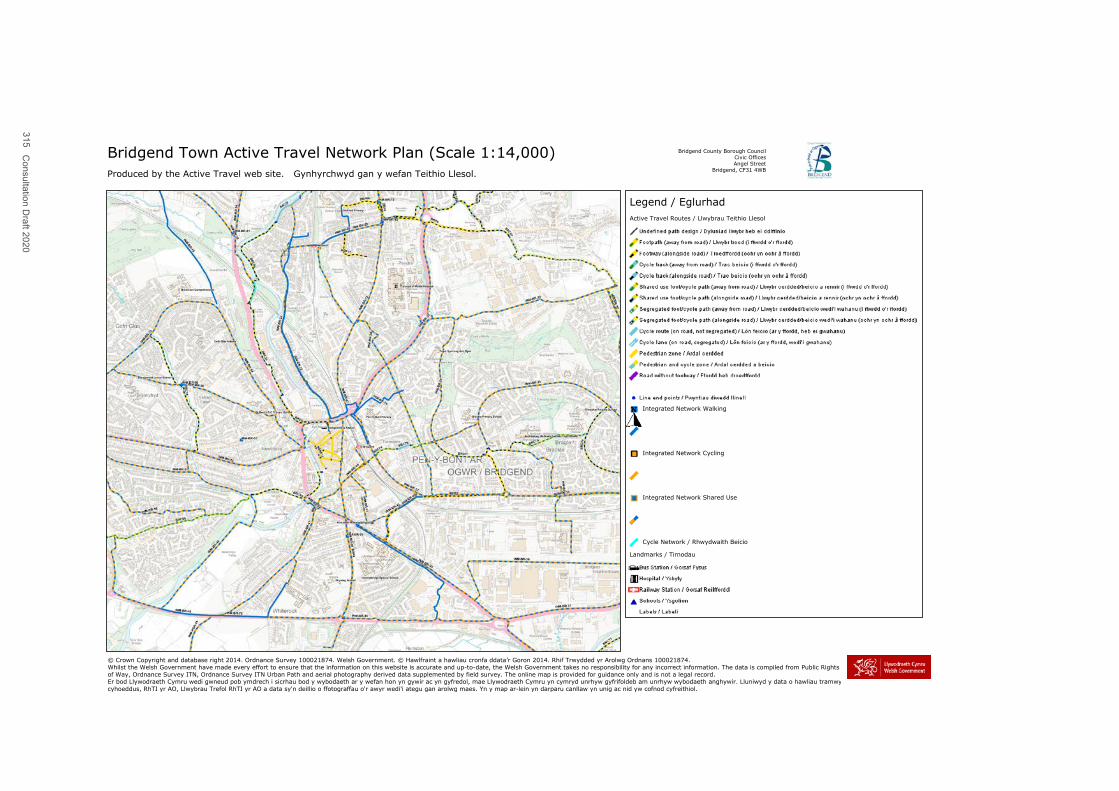
315C
onsultation Draft 2020
Bridgend Town Active Travel Network Plan (Scale 1:14,000)Produced by the Active Travel web site. Gynhyrchwyd gan y wefan Teithio Llesol.
© Crown Copyright and database right 2014. Ordnance Survey 100021874. Welsh Government. © Hawlfraint a hawliau cronfa ddata’r Goron 2014. Rhif Trwydded yr Arolwg Ordnans 100021874.Whilst the Welsh Government have made every effort to ensure that the information on this website is accurate and up-to-date, the Welsh Government takes no responsibility for any incorrect information. The data is compiled from Public Rights of Way, Ordnance Survey ITN, Ordnance Survey ITN Urban Path and aerial photography derived data supplemented by field survey. The online map is provided for guidance only and is not a legal record.Er bod Llywodraeth Cymru wedi gwneud pob ymdrech i sicrhau bod y wybodaeth ar y wefan hon yn gywir ac yn gyfredol, mae Llywodraeth Cymru yn cymryd unrhyw gyfrifoldeb am unrhyw wybodaeth anghywir. Lluniwyd y data o hawliau tramwy cyhoeddus, RhTI yr AO, Llwybrau Trefol RhTI yr AO a data sy'n deillio o ffotograffau o'r awyr wedi'i ategu gan arolwg maes. Yn y map ar-lein yn darparu canllaw yn unig ac nid yw cofnod cyfreithiol.
Bridgend County Borough CouncilCivic OfficesAngel Street
Bridgend, CF31 4WB
Legend / EglurhadActive Travel Routes / Llwybrau Teithio Llesol
Integrated Network Walking
Integrated Network Cycling
Integrated Network Shared Use
Cycle Network / Rhwydwaith Beicio
Landmarks / Tirnodau
30 Jul 2019 10:38 AM
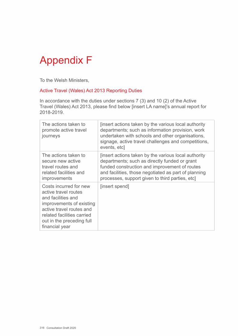
316 Consultation Draft 2020
Appendix F
To the Welsh Ministers,
Active Travel (Wales) Act 2013 Reporting Duties
In accordance with the duties under sections 7 (3) and 10 (2) of the Active Travel (Wales) Act 2013, please find below [insert LA name]’s annual report for 2018-2019.
The actions taken to promote active travel journeys
[insert actions taken by the various local authority departments; such as information provision, work undertaken with schools and other organisations, signage, active travel challenges and competitions, events, etc]
The actions taken to secure new active travel routes and related facilities and improvements
[insert actions taken by the various local authority departments; such as directly funded or grant funded construction and improvement of routes and facilities, those negotiated as part of planning processes, support given to third parties, etc]
Costs incurred for new active travel routes and facilities and improvements of existing active travel routes and related facilities carried out in the preceding full financial year
[insert spend]
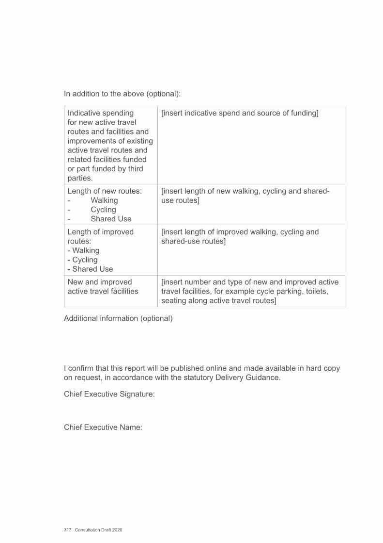
317 Consultation Draft 2020
In addition to the above (optional):
Indicative spending for new active travel routes and facilities and improvements of existing active travel routes and related facilities funded or part funded by third parties.
[insert indicative spend and source of funding]
Length of new routes:- Walking- Cycling- Shared Use
[insert length of new walking, cycling and shared-use routes]
Length of improved routes:- Walking - Cycling- Shared Use
[insert length of improved walking, cycling and shared-use routes]
New and improved active travel facilities
[insert number and type of new and improved active travel facilities, for example cycle parking, toilets, seating along active travel routes]
Additional information (optional)
I confirm that this report will be published online and made available in hard copy on request, in accordance with the statutory Delivery Guidance.
Chief Executive Signature:
Chief Executive Name:
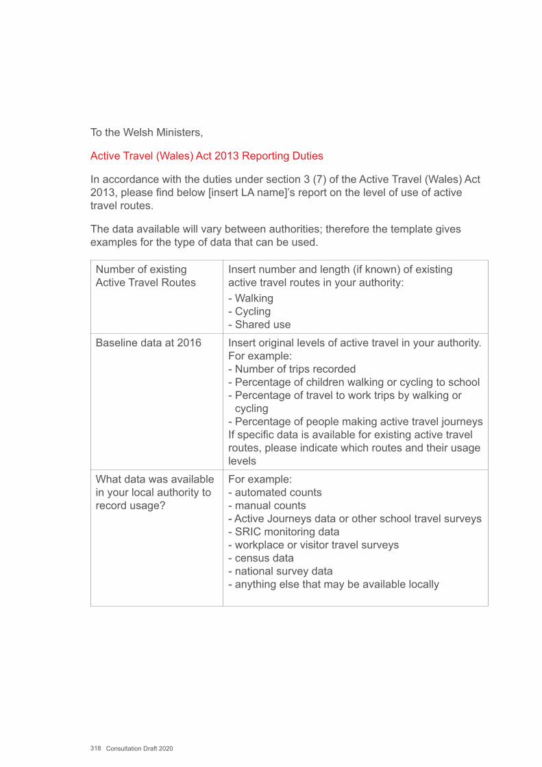
318 Consultation Draft 2020
To the Welsh Ministers,
Active Travel (Wales) Act 2013 Reporting Duties
In accordance with the duties under section 3 (7) of the Active Travel (Wales) Act 2013, please find below [insert LA name]’s report on the level of use of active travel routes.
The data available will vary between authorities; therefore the template gives examples for the type of data that can be used.
Number of existing Active Travel Routes
Insert number and length (if known) of existing active travel routes in your authority:- Walking- Cycling- Shared use
Baseline data at 2016 Insert original levels of active travel in your authority. For example:- Number of trips recorded- Percentage of children walking or cycling to school - Percentage of travel to work trips by walking or
cycling- Percentage of people making active travel journeys If specific data is available for existing active travel routes, please indicate which routes and their usage levels
What data was available in your local authority to record usage?
For example:- automated counts- manual counts- Active Journeys data or other school travel surveys- SRIC monitoring data- workplace or visitor travel surveys- census data- national survey data- anything else that may be available locally

319 Consultation Draft 2020
New data at 2017 Insert current levels of active travel in your authority For example:- Number of trips recorded- Number of children walking or cycling to school - Percentage of active travel as a mode of transport- Indicate existing active travel route(s) if specific is
available as a comparison against baseline dataWhat data will be available to support the next iteration of this report?
Insert anticipated methods e.g. counters on new routes
(Feel free to adapt the template to suit your requirements)
I confirm that this report will be published online and made available in hard copy on request, in accordance with the statutory Delivery Guidance.
Chief Executive
320 Consultation Draft 2020
Appendix G
Design ElementsDE001 – Footway DE002 – Footpath DE003 – Ramp DE004 – StepsDE005 – Raised Table Junction DE006 – Sinusoidal HumpDE007 – Cycle Bypass at NarrowingDE008 – Cycle-Only Access with Right
Turn Facility DE009 – Segregated Contraflow Cycle
Lane DE010 – Unsegregated Contraflow
CyclingDE011 – Quiet Streets DE012 – Cycle StreetsDE013 – Mandatory Cycle Lane DE014 – Advisory Cycle LaneDE015 – Cycle Lane Passing Car
Parking/Loading DE016 – Cycle Lane at Side RoadDE017 – Cycle Lanes with Removal of
Centrelines DE018 – Cycle Lane with Light
SegregationDE019 – Cycle Lane with Light
Segregation at Side Road DE020 – Car Parking/Loading with
Light Segregation DE021 – Hybrid Cycle TrackDE022 – Hybrid Cycle Track at Side
RoadDE023 – Cycle Track Alongside Road,
Separated from Pedestrians DE024 – Cycle Track Alongside Road,
Shared With Pedestrians DE025 – Cycle Track at Side Road with
Cycle PriorityDE026 – Cycle Track at Side Road,
Cyclists Give Way DE027 – Two-Way Cycle Track in
Centre of Carriageway
DE028 – Bus Stop: Cycle Lane BypassDE029 – Bus Stop: Island Bus Stop DE030 – Bus Stop: Bus Boarder DE031 – Bus Stop: Shared UseDE032 – Cycle Track Away From Road,
Separated From Pedestrians DE033 – Cycle Track Away From Road,
Shared With Pedestrians DE034 – Transition Between
Carriageway And Cycle TrackDE035 – Bus LaneDE036 – Simple Uncontrolled
Crossings (Walking, Shared Use or Cycle Only)
DE037 – Cycle Priority CrossingDE038 – Uncontrolled Crossing With
Central Refuge DE039 – Side Road Entry TreatmentDE040 – Blended Side Road Entry
Treatment DE041 – Central Median StripDE042 – Zebra CrossingDE043 – Parallel Crossing for
Pedestrians and Cyclists DE044 – Puffin and Ped-X CrossingsDE045 – Toucan Crossing DE046 – Pedestrian/Cycle Bridge DE047 – Subway/Underpass DE048 – Wheeling RampDE049 – Unmarked Informal JunctionDE050 – Advanced Stop LineDE051 – Cycle Bypass at Traffic
SignalsDE052 – Cycle Lanes Through
Signalised Junction DE053 – Two Stage Right Turn at
Traffic Signals DE054 – Mini Roundabout
DE055 – Compact (“Continental”) Roundabout
DE056 - Dutch Style Roundabout

321 Consultation Draft 2020
Notes:
1. These Design Elements provide concise guidance, includingdimensioned drawings where appropriate, on the layout and use ofparticular types of design solution.
In order to enable authorities to gain experience in the use of moreinnovative techniques, as well as being able to apply more well-established solutions with confidence, each Design Element has beengiven one of three statuses, defined as.
Standard DetailsDetails that are well understood and should generally be applied as shown unless there are particular reasons for local variation.
Suggested DetailsDetails that have not been widely applied in Wales but may be considered appropriate for use in the circumstances as advised.
Possible DetailsDetails that are largely untested in Wales but have been used successfully in other places and may be considered for use in pilot schemes to gain further experience.
Within this document those elements denoted as Standard Details will be regarded as “standards” for the purposes of section 3(6)(a) of the Active Travel Act.
The use of advice categorised as Suggested Details or Possible Details will require careful monitoring by the highway authorities who implement them. More details of monitoring processes can be found inChapter 20.
2. The drawings and images provided are illustrative and will not coverall circumstances. They should be applied in the light of local context.Where appropriate references are given to other documents that willprovide relevant advice, but readers should ensure that they any suchdocuments are the current editions.
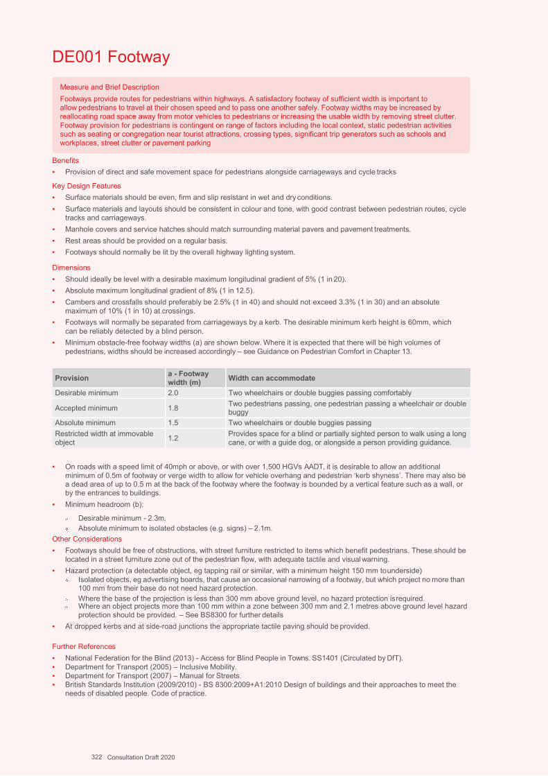
Design Guidance: Active Travel (Wales) Act 2013
276276version 1 -
DDececemembberer 20201414
Measure and Brief DescriptionFootways provide routes for pedestrians within highways. A satisfactory footway of sufficient width is important to allow pedestrians to travel at their chosen speed and to pass one another safely. Footway widths may be increased byreallocating road space away from motor vehicles to pedestrians or increasing the usable width by removing street clutter. Footway provision for pedestrians is contingent on range of factors including the local context, static pedestrian activities such as seating or congregation near tourist attractions, crossing types, significant trip generators such as schools and workplaces, street clutter or pavement parking
DE001 Footway
Benefits▪ Provision of direct and safe movement space for pedestrians alongside carriageways and cycle tracks
Key Design Features▪ Surface materials should be even, firm and slip resistant in wet and dry conditions.▪ Surface materials and layouts should be consistent in colour and tone, with good contrast between pedestrian routes, cycle
tracks and carriageways.▪ Manhole covers and service hatches should match surrounding material pavers and pavement treatments.▪ Rest areas should be provided on a regular basis.▪ Footways should normally be lit by the overall highway lighting system.
Dimensions▪ Should ideally be level with a desirable maximum longitudinal gradient of 5% (1 in 20).▪ Absolute maximum longitudinal gradient of 8% (1 in 12.5).▪ Cambers and crossfalls should preferably be 2.5% (1 in 40) and should not exceed 3.3% (1 in 30) and an absolute
maximum of 10% (1 in 10) at crossings.▪ Footways will normally be separated from carriageways by a kerb. The desirable minimum kerb height is 60mm, which
can be reliably detected by a blind person.▪ Minimum obstacle-free footway widths (a) are shown below. Where it is expected that there will be high volumes of
pedestrians, widths should be increased accordingly – see Guidance on Pedestrian Comfort in Chapter 13.
Provision a - Footway width (m) Width can accommodate
Desirable minimum 2.0 Two wheelchairs or double buggies passing comfortably
Accepted minimum 1.8 Two pedestrians passing, one pedestrian passing a wheelchair or double buggy
Absolute minimum 1.5 Two wheelchairs or double buggies passingRestricted width at immovable object 1.2 Provides space for a blind or partially sighted person to walk using a long
cane, or with a guide dog, or alongside a person providing guidance.
▪ On roads with a speed limit of 40mph or above, or with over 1,500 HGVs AADT, it is desirable to allow an additionalminimum of 0.5m of footway or verge width to allow for vehicle overhang and pedestrian ‘kerb shyness’. There may also bea dead area of up to 0.5 m at the back of the footway where the footway is bounded by a vertical feature such as a wall, orby the entrances to buildings.
▪ Minimum headroom (b):
Desirable minimum - 2.3m.Absolute minimum to isolated obstacles (e.g. signs) – 2.1m.
Other Considerations▪ Footways should be free of obstructions, with street furniture restricted to items which benefit pedestrians. These should be
located in a street furniture zone out of the pedestrian flow, with adequate tactile and visualwarning.▪ Hazard protection (a detectable object, eg tapping rail or similar, with a minimum height 150 mm tounderside)
Isolated objects, eg advertising boards, that cause an occasional narrowing of a footway, but which project no more than 100 mm from their base do not need hazard protection.Where the base of the projection is less than 300 mm above ground level, no hazard protection isrequired.Where an object projects more than 100 mm within a zone between 300 mm and 2.1 metres above ground level hazard protection should be provided. – See BS8300 for further details
▪ At dropped kerbs and at side-road junctions the appropriate tactile paving should be provided.
Further References▪ National Federation for the Blind (2013) - Access for Blind People in Towns. SS1401 (Circulated by DfT).▪ Department for Transport (2005) – Inclusive Mobility.▪ Department for Transport (2007) – Manual for Streets.▪ British Standards Institution (2009/2010) - BS 8300:2009+A1:2010 Design of buildings and their approaches to meet the
needs of disabled people. Code of practice.
322 Consultation Draft 2020
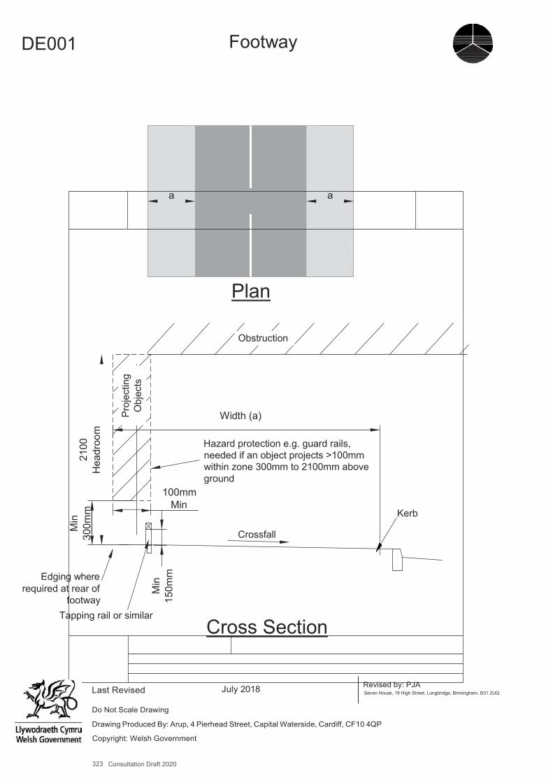
323 Consultation Draft 2020
A4
DE001 Footway
a a
Plan
Obstruction
Width (a)
100mm Min
Hazard protection e.g. guard rails, needed if an object projects >100mm within zone 300mm to 2100mm above ground
Crossfall
Kerb
Edging where required at rear of
footway Tapping rail or similar
Cross Section
Last Revised
Revised by: PJA Seven House, 18 High Street, Longbridge, Birmingham, B31 2UQ
Do Not Scale Drawing
Drawing Produced By: Arup, 4 Pierhead Street, Capital Waterside, Cardiff, CF10 4QP
Copyright: Welsh Government
Min
30
0mm
21
00
Hea
droo
m
Proj
ectin
g O
bjec
ts
Min
15
0mm
July 2018
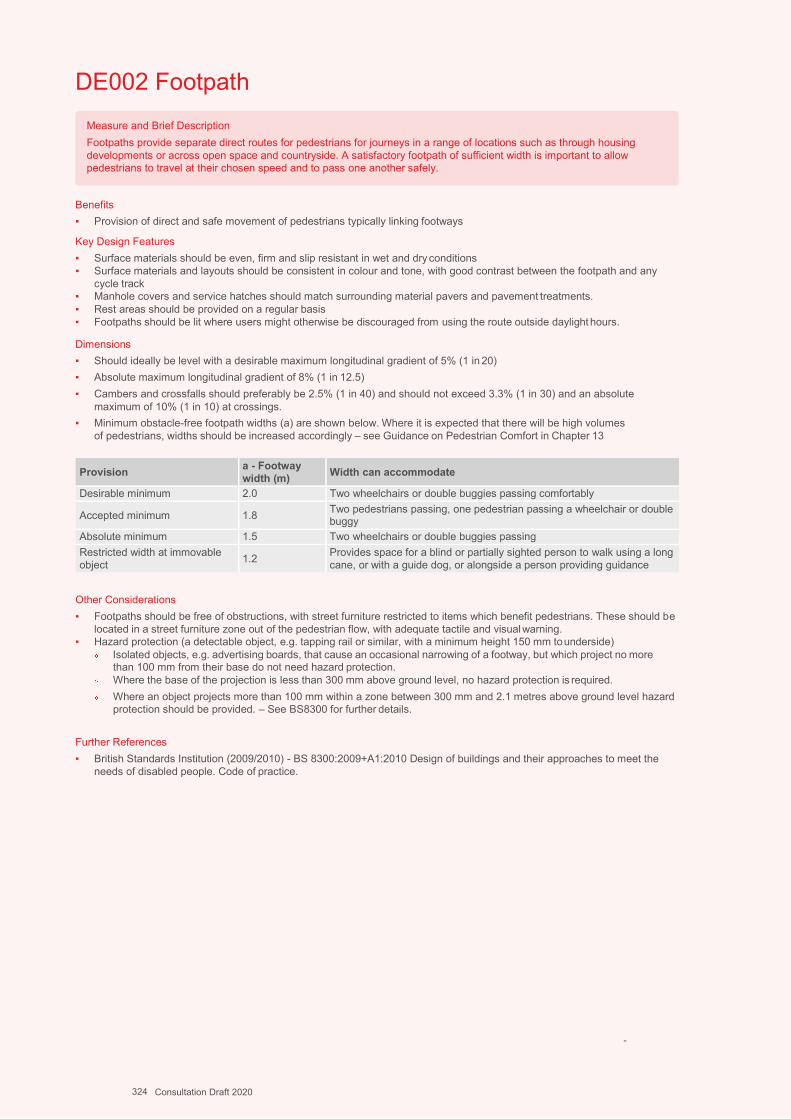
Design Guidance: Active Travel (Wales) Act 2013
278278version 1 -
DDececemembberer 20201414
Measure and Brief DescriptionFootpaths provide separate direct routes for pedestrians for journeys in a range of locations such as through housing developments or across open space and countryside. A satisfactory footpath of sufficient width is important to allow pedestrians to travel at their chosen speed and to pass one another safely.
DE002 Footpath
Benefits▪ Provision of direct and safe movement of pedestrians typically linking footways
Key Design Features▪ Surface materials should be even, firm and slip resistant in wet and dry conditions▪ Surface materials and layouts should be consistent in colour and tone, with good contrast between the footpath and any
cycle track▪ Manhole covers and service hatches should match surrounding material pavers and pavement treatments.▪ Rest areas should be provided on a regular basis▪ Footpaths should be lit where users might otherwise be discouraged from using the route outside daylight hours.
Dimensions▪ Should ideally be level with a desirable maximum longitudinal gradient of 5% (1 in 20)▪ Absolute maximum longitudinal gradient of 8% (1 in 12.5)▪ Cambers and crossfalls should preferably be 2.5% (1 in 40) and should not exceed 3.3% (1 in 30) and an absolute
maximum of 10% (1 in 10) at crossings.▪ Minimum obstacle-free footpath widths (a) are shown below. Where it is expected that there will be high volumes
of pedestrians, widths should be increased accordingly – see Guidance on Pedestrian Comfort in Chapter 13
Provision a - Footway width (m) Width can accommodate
Desirable minimum 2.0 Two wheelchairs or double buggies passing comfortably
Accepted minimum 1.8 Two pedestrians passing, one pedestrian passing a wheelchair or double buggy
Absolute minimum 1.5 Two wheelchairs or double buggies passingRestricted width at immovable object 1.2 Provides space for a blind or partially sighted person to walk using a long
cane, or with a guide dog, or alongside a person providing guidance
Other Considerations▪ Footpaths should be free of obstructions, with street furniture restricted to items which benefit pedestrians. These should be
located in a street furniture zone out of the pedestrian flow, with adequate tactile and visualwarning.▪ Hazard protection (a detectable object, e.g. tapping rail or similar, with a minimum height 150 mm tounderside)
Isolated objects, e.g. advertising boards, that cause an occasional narrowing of a footway, but which project no more than 100 mm from their base do not need hazard protection.Where the base of the projection is less than 300 mm above ground level, no hazard protection is required.Where an object projects more than 100 mm within a zone between 300 mm and 2.1 metres above ground level hazard protection should be provided. – See BS8300 for further details.
Further References▪ British Standards Institution (2009/2010) - BS 8300:2009+A1:2010 Design of buildings and their approaches to meet the
needs of disabled people. Code of practice.
-
324 Consultation Draft 2020
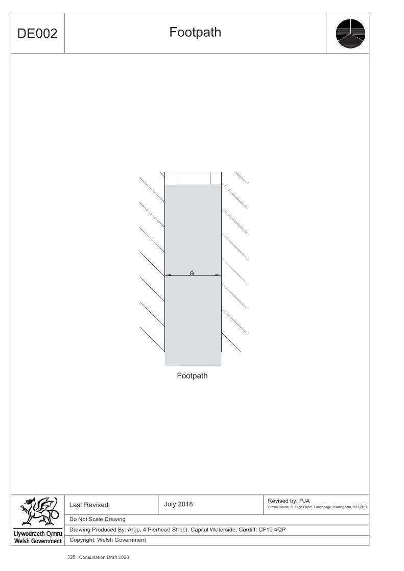
325 Consultation Draft 2020
A4
DE002 Footpath
a
Footpath
Last Revised July 2018 Revised by: PJA Seven House, 18 High Street, Longbridge, Birmingham, B31 2UQ
Do Not Scale Drawing
Drawing Produced By: Arup, 4 Pierhead Street, Capital Waterside, Cardiff, CF10 4QP
Copyright: Welsh Government

Design Guidance: Active Travel (Wales) Act 2013
280280 version 1 -
DDececemembberer 20201414
Measure and Brief Description Ramps (defined as a gradient of more than 5 % (1 in 20)) are provided to facilitate a change in level or grade on a walking route. They should only be used where a change in level or grade cannot be avoided. In many places ramps will provide the alternative access to stairs for wheelchair users.
DE003 Ramp
Benefits ▪ Ramps provide an accessible alternative to steps for disabled people, older people and parents and carers with pushchairs.
Key Design Features ▪ Where the change in level is no more than 200mm a ramp may be used without alternative steps. ▪ Desirable Maximum Gradient – 5% (1 in 20). ▪ Absolute Maximum Gradient – 8% (1 in 12). Steeper ramps will cause difficulties for manual wheelchair users. ▪ Absolute Maximum Gradient over short distances (max 1m) - 10% (1 in 10) - eg on a ramp between a bus entrance andthe
pavement.
Dimensions ▪ Ramp surface width
Preferred Minimum– 2m Desirable Minimum – 1.8m Absolute Minimum – 1.2m
▪ Sides of a ramp should be protected by a raised solid kerb at least 100mm in height. ▪ If kerb height exceeds 75mm there must be no slot or gap greater than 20mm in the range of 75mm to 150mm. This is done
to avoid the possibility of the footplate of a wheelchair riding over the kerb or becoming trapped. ▪ Ramp-side face of the kerb to be flush with, or no more than 100mm away from, the ramp-side face of the handrail. ▪ Handrails should be provided on each side, with a minimum clear width rail to rail of 1,000mm. Where this unobstructed
width exceeds 2000mm, a central, continuous handrail may be used as an alternative to a handrail on each side. ▪ Handrails should be provided on both sides of stairways and ramps and down the centre of stairs when their unobstructed
width (ie between handrails) exceeds 1,800mm. ▪ Recommended height to the top of the principal handrail is between 900mm and 1000mm above the pitchline of the steps
or above the surface of the ramp. On landings the top of the handrail should be between 900mm and 1100mm from the surface.
▪ Handrails should continue beyond the end of the ramp slope or end of the stairs by a (minimum) distance of 300mm and should either return to the wall or down to the floor or have a minimum rounded downturn of 100mm.
▪ Second, lower handrails for children and people of restricted growth are helpful and should be at heights of between 550mm and 650mm.
▪ The handrail itself should be smooth and comfortable to use by people with arthritic hands that is they should not be too small in diameter. Circular handrails should have a diameter between 40mm and 50mm; if not circular the handrail should be a maximum of 50mm wide by 38mm deep with rounded edges (radius of at least 15mm).
▪ There should be a clear space between the handrail and any adjacent wall of at least 50mm, preferably 60mm. Handrails should be supported centrally on the underside so there is no obstruction to the passage of the hand along the rail. There should also be a minimum of 600mm clear space above the handrail.
Other Considerations ▪ There is a relationship between the length of a ramp and the gradient that people can manage; the longer the ramp the less
severe the gradient that is feasible. One possible approach to this is, where a lengthy ramp is necessary, to design more frequent landings and lesser slopes for each successive segment.
▪ Ramps should never be longer than 132 metres in total and preferably no longer than 50 metres. ▪ Means should be provided to limit the risk of people colliding with the underside of freestanding ramps at any point where
the clear height is less than 2.1m. ▪ The transition between the level and inclined parts of the ramp should be sufficiently rounded to ensure that a wheelchair
user does not get caught by the foot supports.
Further References ▪ Department for Transport (2005) – Inclusive Mobility.
326 Consultation Draft 2020

327 Consultation Draft 2020
A4
DE003 Ramps
1.2 m (min)
10 m (max)
Level 1.5 m (1:50 if outside (min) for drainage)
Slope 1:20 (5%) 10 m (1:12.5 (8%) max) (max)
1.2 m Level (min) (1:50 if outside for drainage)
Slope 1:20 (5%) (1:12.5 (8%) max)
2.0 m (min) Level 1.2 m (min) (1.0m
Where width between (1:50 if outside for drainage) absolute min)
handrails > 2.0 m central handrail required
Ramp key dimensions 60 mm
(50 mm min) Handrail 40 - 50 mm dia
Crossfall where
900 required for drainage mm
2.5% 100 mm kerb or lower rail
Section through ramp
Last Revised July 2018 Revised by: PJA Seven House, 18 High Street, Longbridge, Birmingham, B31 2UQ
Do Not Scale Drawing
Drawing Produced By: Arup, 4 Pierhead Street, Capital Waterside, Cardiff, CF10 4QP
Copyright: Welsh Government
Design Guidance: Active Travel (Wales) Act 2013
282282version 1 -
DDececemembberer 20201414
DE004 Steps
Benefits▪ Direct routes for pedestrians.▪ Steps can provide a useful shortcut to maintain desire lines where it is necessary to also provide a ramp to accommodate a
change in level or grade.▪ Steps built within public spaces are particularly popular because they can also serve as a good lookoutpoint.
Key Design Features▪ Steps should usually only be provided in conjunction with a ramp (or lift) in order to retain accessibility for disabled people,
older people and parents and carers with pushchairs.
Dimensions▪ A riser height of 150mm can be managed by most people; a little more than this is possible if there are well designed
handrails but 170mm should be regarded as the absolute maximum in most circumstances. Steps with very shallow risers can cause problems and should be avoided; 100mm is the absolute minimum. All steps in a flight must have the same dimensions.
▪ Tread depth or going should be 300mm deep (approximately the length of a size 9 shoe), with an absolute minimum of 250mm.
▪ The nose of the step should be rounded (6mm radius) without any overhang.▪ Steps should be well lit (minimum 200 lux, and surfaced with a slip resistant material.▪ Colour/tonal contrast on the step noses is beneficial for visually impaired people and should extend across the full width of
each tread, 55mm deep on both tread and riser.▪ The maximum number of risers in a flight should be 12, with resting places between successive flights. Resting places
should have a Desirable Minimum length of 1.8m and an Absolute Minimum length of 1.2m, and be across the full width of the steps. The minimum number of steps in a flight should be three; fewer than this is less safe.
▪ The Desirable Minimum clear width between handrails is 1.2m which is sufficient for a disabled person and companion, with an Absolute Minimum width of 1m.
▪ Handrails should be provided on both sides and, where steps have a clear width of more than 1.8m, a centre handrail should also be provided.
Other Considerations▪ Means should be provided to limit the risk of people colliding with the underside of freestanding steps at any point wherethe
clear height is less than 2.1m.▪ Incorporation of corduroy warning paving to the top and bottom, and visual contrast between elements should be used to
highlight features such as steps edges and handrails.▪ Open tread steps are to be avoided, as are curved or spiral steps.▪ There should be unobstructed landing space at the top and bottom of each flight of steps of a length at least equal to the
unobstructed width of the steps.
Further References▪ Department for Transport (2005) – Inclusive Mobility.
Measure and Brief DescriptionSteps allow direct movement for pedestrians from one level to another where there would otherwise be a significant gradient.
328 Consultation Draft 2020

329 Consultation Draft 2020
A4
DE004 Steps
55 mm Strip of contrasting tone/colour on riser
and tread
Tread 370 mm (max) 55 mm 250 mm (min)
Step nose rounded (6 mm radius)
Resting places Provide a resting place (landing) 1.8 m
Riser long (1.2 m min) every 12 risers.
170 mm (max) Number of steps in a flight 100 mm (min) 12 risers (max)
Clear width 1.2 m 3 risers (min) (1.0 m min)
1.2 m (min) (1.0m Where width between
absolute min) Pitch (angle) of steps handrails > 1.8 m central 25° (min) handrail required* 35° (max for high usage) 60 mm Handrail 40 - 50 mm 45° (absolute max) (50 mm min) dia
Rule of thumb: tread length + 2 x riser height = 600 mm 900
Steps key dimensions mm * Note: This precludes the use of stairs with a clear width between 1.8 and 2.0 m
Section through steps
Last Revised July 2018 Revised by: PJA Seven House, 18 High Street, Longbridge, Birmingham, B31 2UQ
Do Not Scale Drawing
Drawing Produced By: Arup, 4 Pierhead Street, Capital Waterside, Cardiff, CF10 4QP
Copyright: Welsh Government
Design Guidance: Active Travel (Wales) Act 2013
284284 version 1 -
DDececemembberer 20201414
DE005 Raised Table Junction
Benefits ▪ Raised tables emphasise the presence of a junction, encourage driver attention and lead to drivers giving informal priority to
pedestrians. ▪ By reducing speeds, raised table junctions will commonly not require separate cycle facilities. ▪ The speed reduction effect of raised tables can be used to mitigate reduced visibility at some low volume/low speed
junctions. ▪ Raised table junctions included as part of wider traffic calming measures can discourage through traffic.
Key Design Features ▪ The raised table must comply with the Highways (Road Humps) Regulations 1999. ▪ The raised table should extend from kerb to kerb to benefit pedestrians crossing. This will require attention to drainage
requirements to avoid standing water at the ramps. ▪ Appropriate tactile paving should be provided at pedestrian crossing points. ▪ Approach ramps should be located sufficiently far from the junction mouth so that the changing level of the carriageway
does not become problematic for cyclists when turning. ▪ It may be necessary to install build outs, bollards or introduce parking restrictions as appropriate in order to prevent parking
around the junction. ▪ Drainage covers/gully gratings set flush with the footway to avoid becoming a hazard for pedestrians and cyclists.
Dimensions ▪ Approach ramps with a sinusoidal profile will reduce discomfort for cyclists compared to a 1 in 10 ramp. ▪ Table height should normally be 75mm, maximum 100mm. ▪ Kerb radii to be reduced to 2-3m, subject to vehicle tracking (and allowing for vehicles to cross centrelines unless flows are
high).
Other Considerations ▪ Bollards may be provided to prevent over-run on corners. ▪ Strengthened corners may be necessary if over-run is to be expected. ▪ Raised tables can usefully be provided between junctions, using similar design criteria.
Further References ▪ Department for Transport (2007) – Local Transport Note 01/07. Traffic Calming.
-
Measure and Brief Description Raised table junctions create safer environments for all users by reducing the speed of vehicles negotiating the junction. They are typically used at priority junctions but can also be applied to roundabouts (including mini roundabouts and implied roundabouts) and traffic signals.
Raised table junctions can be used on roads with a speed limit of 30mph or less, with adequate street lighting provision, in the following situations: ▪ urban/suburban residential and mixed use areas; and ▪ in town centres as part of public realm improvements, where raised tables at key junctions provide informal crossing
points for pedestrians.
Raised table junctions are road humps and must comply with the Highways Act 1980, Sections 90A to 90F.
330 Consultation Draft 2020
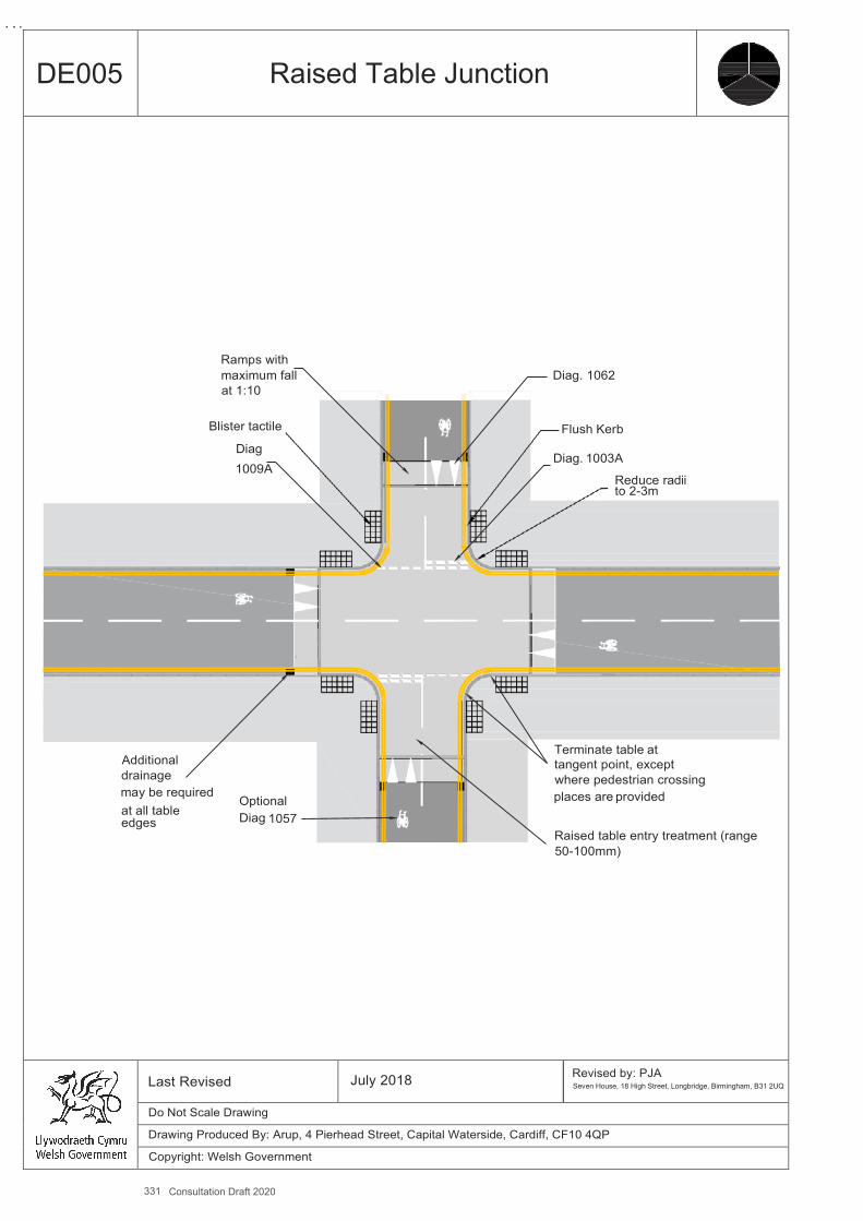
331 Consultation Draft 2020
A4
DE005 Raised Table Junction
Ramps with maximum fall Diag. 1062 at 1:10
Blister tactile Flush Kerb
Diag Diag. 1003A
1009A Reduce radii to 2-3m
Terminate table at Additional tangent point, except drainage where pedestrian crossing may be required
Optional places are provided at all table Diag 1057 edges
Raised table entry treatment (range 50-100mm)
Last Revised July 2018 Revised by: PJA Seven House, 18 High Street, Longbridge, Birmingham, B31 2UQ
Do Not Scale Drawing
Drawing Produced By: Arup, 4 Pierhead Street, Capital Waterside, Cardiff, CF10 4QP
Copyright: Welsh Government

Design Guidance: Active Travel (Wales) Act 2013
286286 version 2 -
December 2014
DE006 Sinusoidal Hump
Benefits ▪ Sinusoidal road humps minimise discomfort for passing cyclists and are effective at reducing motor-vehicle speeds. ▪ Improve perceived and actual safety for pedestrians and cyclists. ▪ Reduction in traffic speeds helps improve cyclist comfort and help create suitable cycle routes. ▪ Helps reduce the necessity for speed limit enforcement by Police. ▪ Can improve living conditions for residents living along traffic calmed roads.
Key Design Features ▪ The sinusoidal road hump must comply with the Highways (Road Humps) Regulations 1999. ▪ As an exact profile may be difficult to construct an approximate sinusoidal profile is acceptable, with a tapered entry and exit
profile. ▪ The impacts on car parking should be considered.
Dimensions ▪ Hump height should normally be 75mm, maximum 100mm, see also Local Transport Note 1/07.
Other Considerations ▪ Where a drainage gap is provided at the edge of a sinusoidal hump it should not be wide enough that drivers useit. ▪ Councils are required to advertise and consult on sinusoidal humps, flat-top humps and speed cushions under the Highways
(Road Hump) Regulations 1999.
Further References ▪ Department for Transport (2007) – Local Transport Note 01/07. Traffic Calming.
-
Measure and Brief Description Traffic calming measures are used to reduce motor vehicle speeds thereby improving safety for pedestrians and cyclists as well as improving living conditions for residents living along traffic calmed routes. The provision of sinusoidal profile humps reduces the discomfort for cyclists when riding over humps, whilst still being effective in reducing traffic speed.
Sinusoidal humps are road humps and must comply with the Highways Act 1980, Sections 90A to 90F.
332 Consultation Draft 2020
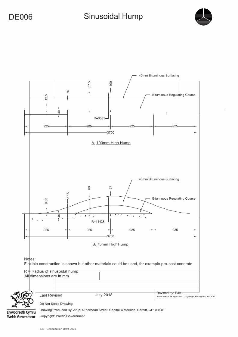
333 Consultation Draft 2020
A4
DE006 Sinusoidal Hump
40mm Bituminous Surfacing
Bituminous Regulating Course
R=8581
925 925 925
3700
A. 100mm High Hump
40mm Bituminous Surfacing
Bituminous Regulating Course
R=11438
925 925
3700 B. 75mm High Hump
925
Notes: Flexible construction is shown but other materials could be used, for example pre-cast concrete
R = Radius of sinusoidal hump All dimensions are in mm
Last Revised July 2018 Revised by: PJA Seven House, 18 High Street, Longbridge, Birmingham, B31 2UQ
Do Not Scale Drawing
Drawing Produced By: Arup, 4 Pierhead Street, Capital Waterside, Cardiff, CF10 4QP
Copyright: Welsh Government
925
925
9.00
12
.5
40
40
37.5
50
60
87.5
75
100

A4
L288
DE007 Cycle Bypass at Narrowing
Benefits ▪ Cyclists are not intimidated or squeezed by motor traffic. ▪ Improve perceived and actual safety for pedestrians and cyclists. ▪ Reduction in traffic speed helps improve cyclist comfort and create suitable cycle routes. ▪ Helps reduce the necessity for speed limit enforcement. ▪ Can improve living conditions for residents living along traffic calmed roads.
Key Design Features ▪ Cycle bypass exits should not require cyclists to merge abruptly with motor vehicles. ▪ Parking and loading/waiting restrictions should be provided to avoid cycle bypasses becoming blocked by vehicles. ▪ Careful consideration should also be given to drainage at cycle by-passes to minimise gully grate conflict and flooding inthe
area. ▪ Bypasses should be wide enough to facilitate maintenance, e.g. street sweeper vehicles.
Dimensions ▪ a - cycle bypass to traffic calming features to be 2m desirable min (1.5m absolute minimum). ▪ b - gap for traffic between traffic calming features to be 3m max. ▪ c - avoid pinch point distances of between 3.1 - 3.9m – see Table 4.6.
Other Considerations ▪ Bypasses should desirably be at carriageway level, in which case regular sweeping will be necessary. ▪ Footway level bypasses should consider impact on pedestrians, and additional drainage will be required.
Further References ▪ Department for Transport (2007) – Local Transport Note 01/07. Traffic Calming.
Measure and Brief Description Traffic calming measures are used to reduce motor vehicle speed thereby improving safety for pedestrians and cyclists as well as improving living conditions for residents living along traffic calmed routes. Traffic calming can improve cycling conditions, but where poorly designed it can also be uncomfortable and in some cases be intimidating and dangerous. Where horizontal traffic calming features are provided consideration should be given to providing bypasses for cyclists.
334 Consultation Draft 2020
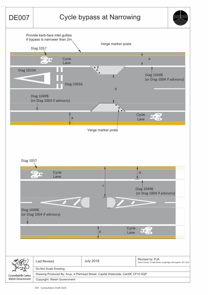
335 Consultation Draft 2020
A4
DE007 Cycle bypass at Narrowing
Provide kerb-face inlet gullies if bypass is narrower than 2m
Verge marker posts Diag 1057
Cycle a Lane
Diag 1023A Diag 1049B (or Diag 1004 if advisory)
Diag 1003A b
Diag 1049B (or Diag 1004 if advisory)
Cycle a Lane
Verge marker posts
Diag 1057
Cycle a Lane
c
Diag 1049B (or Diag 1004 if advisory)
Diag 1049B (or Diag 1004 if advisory)
Cycle a Lane
Last Revised July 2018 Revised by: PJA
Seven House, 18 High Street, Longbridge, Birmingham, B31 2UQ
Do Not Scale Drawing
Drawing Produced By: Arup, 4 Pierhead Street, Capital Waterside, Cardiff, CF10 4QP
Copyright: Welsh Government
A4
L290
DE008 Cycle-Only Access with Right Turn Facility
Benefits ▪ Reduces cycle journey times. ▪ Increase permeability of area for cyclists. ▪ Provide convenient and attractive routes. ▪ Helps to limit motor vehicle through traffic, and particularly effective in neighbourhoods where extraneous traffic is a
problem, helping to deter unnecessary car trips. ▪ Relatively low cost. ▪ Can be retro-fitted to existing streets.
Key Design Features ▪ Traffic movements are often banned to help ease congestion by deterring traffic from certain streets. It is possible to exempt
cycles from turning bans without having to significantly change the physical nature of the road. ▪ Where a closure is planned the preferred method is by the use of bollards with cycle signing mounted on them. ▪ Demountable bollards can be used to retain access for emergency vehicles. Dedicated right turn pockets for cyclists provide
protection whilst waiting to make a turn.
Dimensions ▪ a - dedicated right turn pockets for cyclists to be 2m desirable min (1.5m absolute minimum). ▪ Width for cyclists at road closure to be 1.5m absolute minimum.
Other Considerations ▪ Consideration should be given to:
The potential for nuisance caused by powered two wheelers. Need to restrict car parking in the vicinity of the cycle gap, eg through double yellow lines. Providing good natural surveillance to deter crime. Potential need to maintain access for emergency vehicles. Pedestrian and cyclist interaction.
▪ Build outs or other features may be needed to keep the cycle gap clear of parked vehicles. ▪ The impact of road closures can be assessed by undertaking a trial closure on a temporary basis. The closure can then be
made permanent if it is found to be successful.
-
Measure and Brief Description Cyclists should be exempted from restrictions applied to motor traffic on links or at junctions where safe to do so, or through the creation of short connections which are only available to cyclists and pedestrians, to give them time and distance advantages. This example shows how a cycle-only access can be provided which includes a central lane to assist right- turning cyclists.
336 Consultation Draft 2020
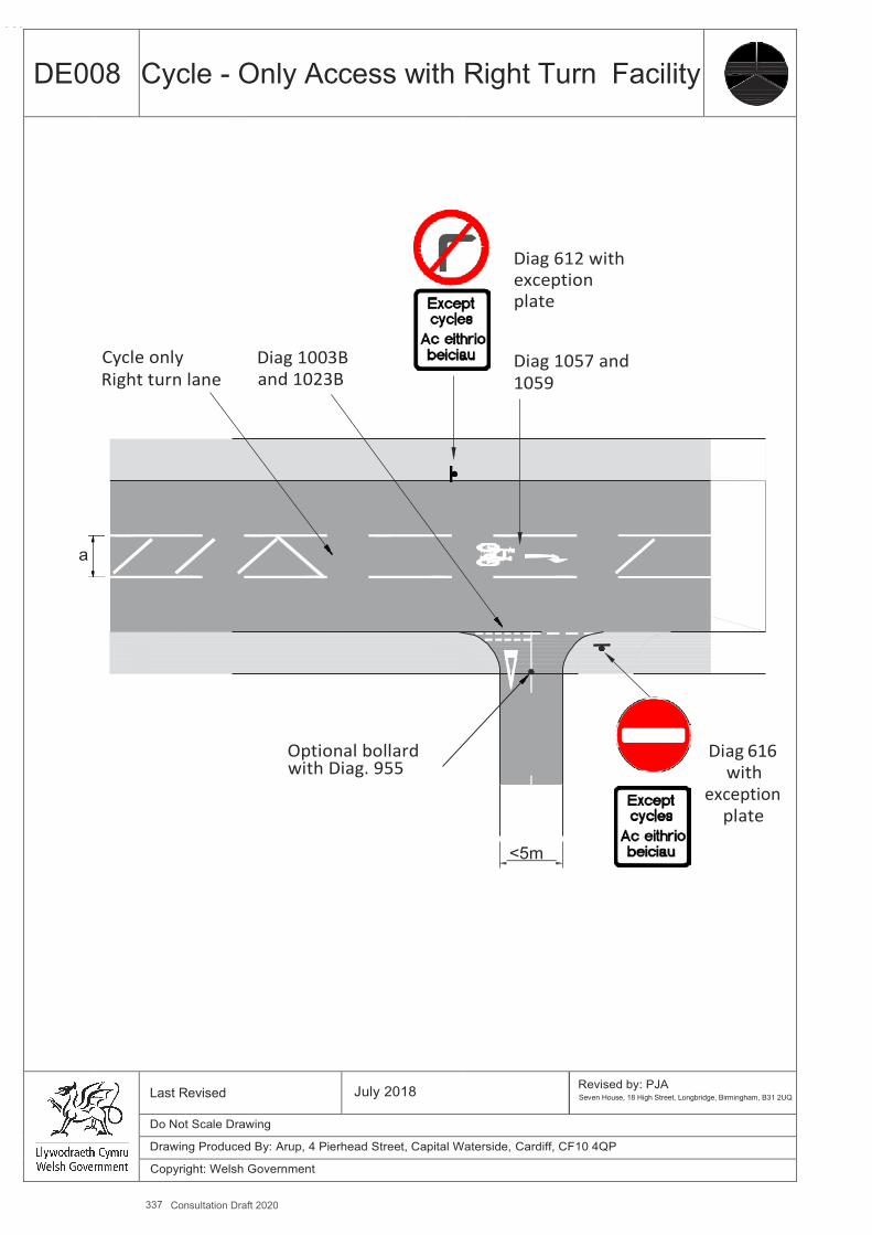
337 Consultation Draft 2020
A4
DE008 Cycle - Only Access with Right Turn Facility
a
Cycle only Right turn lane
Diag 1003B and 1023B
Optional bollard with Diag. 955
Diag 612 with exception plate
Diag 1057 and 1059
<5m.
Diag 616
with exception
plate
Last Revised July 2018 Revised by: PJA
Seven House, 18 High Street, Longbridge, Birmingham, B31 2UQ
Do Not Scale Drawing
Drawing Produced By: Arup, 4 Pierhead Street, Capital Waterside, Cardiff, CF10 4QP
Copyright: Welsh Government
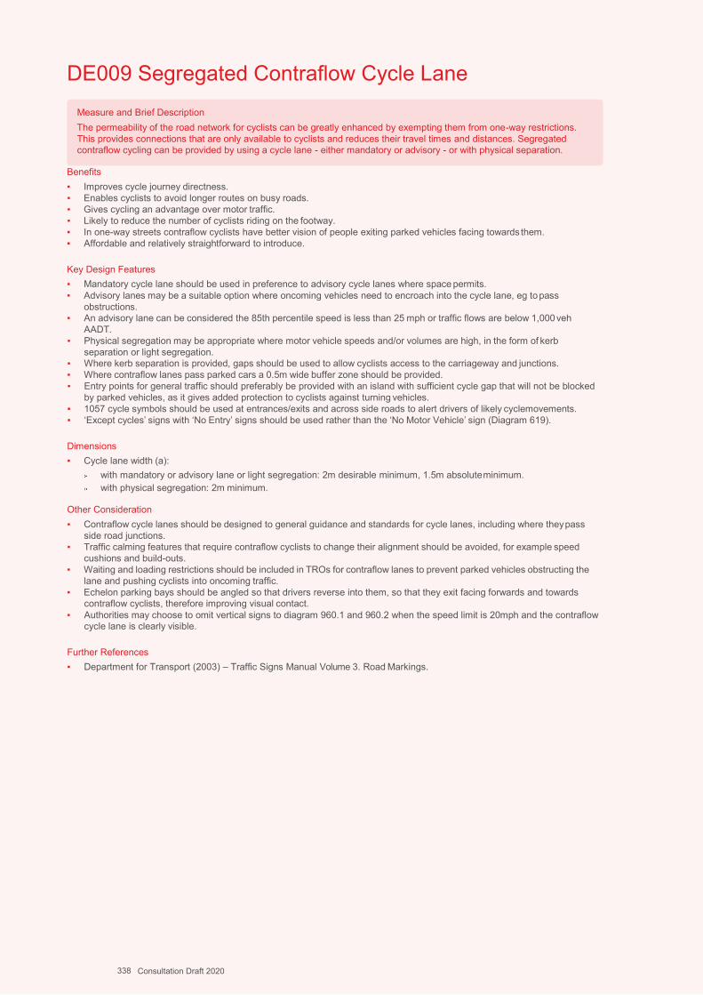
A4
L292
DE009 Segregated Contraflow Cycle Lane
Benefits ▪ Improves cycle journey directness. ▪ Enables cyclists to avoid longer routes on busy roads. ▪ Gives cycling an advantage over motor traffic. ▪ Likely to reduce the number of cyclists riding on the footway. ▪ In one-way streets contraflow cyclists have better vision of people exiting parked vehicles facing towards them. ▪ Affordable and relatively straightforward to introduce.
Key Design Features ▪ Mandatory cycle lane should be used in preference to advisory cycle lanes where space permits. ▪ Advisory lanes may be a suitable option where oncoming vehicles need to encroach into the cycle lane, eg to pass
obstructions. ▪ An advisory lane can be considered the 85th percentile speed is less than 25 mph or traffic flows are below 1,000 veh
AADT. ▪ Physical segregation may be appropriate where motor vehicle speeds and/or volumes are high, in the form of kerb
separation or light segregation. ▪ Where kerb separation is provided, gaps should be used to allow cyclists access to the carriageway and junctions. ▪ Where contraflow lanes pass parked cars a 0.5m wide buffer zone should be provided. ▪ Entry points for general traffic should preferably be provided with an island with sufficient cycle gap that will not be blocked
by parked vehicles, as it gives added protection to cyclists against turning vehicles. ▪ 1057 cycle symbols should be used at entrances/exits and across side roads to alert drivers of likely cyclemovements. ▪ ‘Except cycles’ signs with ‘No Entry’ signs should be used rather than the ‘No Motor Vehicle’ sign (Diagram 619).
Dimensions ▪ Cycle lane width (a):
with mandatory or advisory lane or light segregation: 2m desirable minimum, 1.5m absolute minimum. with physical segregation: 2m minimum.
Other Consideration ▪ Contraflow cycle lanes should be designed to general guidance and standards for cycle lanes, including where they pass
side road junctions. ▪ Traffic calming features that require contraflow cyclists to change their alignment should be avoided, for example speed
cushions and build-outs. ▪ Waiting and loading restrictions should be included in TROs for contraflow lanes to prevent parked vehicles obstructing the
lane and pushing cyclists into oncoming traffic. ▪ Echelon parking bays should be angled so that drivers reverse into them, so that they exit facing forwards and towards
contraflow cyclists, therefore improving visual contact. ▪ Authorities may choose to omit vertical signs to diagram 960.1 and 960.2 when the speed limit is 20mph and the contraflow
cycle lane is clearly visible.
Further References ▪ Department for Transport (2003) – Traffic Signs Manual Volume 3. Road Markings.
Measure and Brief Description The permeability of the road network for cyclists can be greatly enhanced by exempting them from one-way restrictions. This provides connections that are only available to cyclists and reduces their travel times and distances. Segregated contraflow cycling can be provided by using a cycle lane - either mandatory or advisory - or with physical separation.
338 Consultation Draft 2020
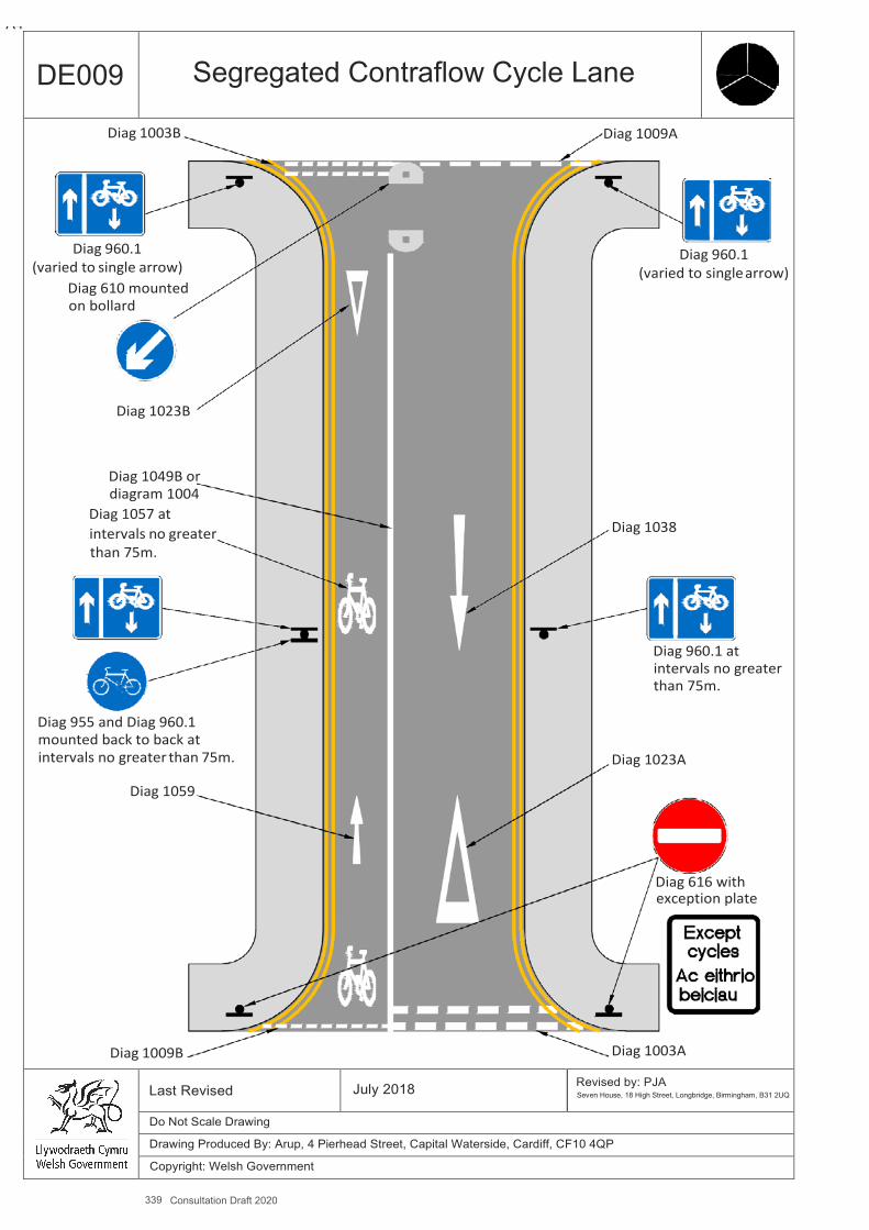
339 Consultation Draft 2020
A4
DE009 Segregated Contraflow Cycle Lane
Diag 1003B Diag 1009A
Diag 960.1 Diag 960.1 (varied to single arrow) (varied to single arrow)
Diag 610 mounted on bollard
Diag 1023B
Diag 1049B or diagram 1004
Diag 1057 at intervals no greater Diag 1038 than 75m.
Diag 960.1 at intervals no greater than 75m.
Diag 955 and Diag 960.1 mounted back to back at intervals no greater than 75m. Diag 1023A
Diag 1059
Diag 616 with exception plate
Diag 1009B Diag 1003A
Last Revised July 2018 Revised by: PJA Seven House, 18 High Street, Longbridge, Birmingham, B31 2UQ
Do Not Scale Drawing
Drawing Produced By: Arup, 4 Pierhead Street, Capital Waterside, Cardiff, CF10 4QP
Copyright: Welsh Government

A4 294
DE010 Unsegregated Contraflow Cycling
Benefits ▪ Improves cycle journey directness. ▪ Enables cyclists to avoid longer routes on busy roads. ▪ Gives cycling an advantage over motor traffic. ▪ Likely to reduce the number of cyclists riding on the footway. ▪ In one-way streets contraflow cyclists have better vision of people exiting parked vehicles facing towards them. ▪ Affordable and relatively straightforward to introduce. ▪ Can be introduced without a cycle lane where traffic volumes and speeds are low.
Key Design Features ▪ Mandatory cycle lane should be used in preference to advisory cycle lanes where space permits. ▪ Where the 85th percentile speed is less than 25 mph and traffic flows are below 1,000 veh AADT, or where the street forms
part of a 20 mph zone. ▪ At entries and exits, consideration should be given to alert drivers and pedestrians of contraflow cycle movements using a
short section of cycle lane. ▪ Cycle logos and directional arrows should be used especially at entrances/exits and across side roads to alert drivers of
likely cycle movements. ▪ ‘Except cycles’ signs with ‘No Entry’ signs should be used rather than the ‘No Motor Vehicle’ sign (Diagram 619).
Dimensions ▪ Sufficient carriageway space is required to ensure cyclists have enough space to pass oncoming vehicles, however it is
possible to facilitate contraflow cycling in lightly trafficked narrow streets, including where there is car parking on one or both sides and a narrow running lane.
▪ a - carriageway width: Absolute minimum 2.6m (no car parking). Desirable minimum 3.85m based on car passing cycle (no car parking). Absolute minimum 4.6m (with car parking on one side).
Other Considerations ▪ 20mph zone with traffic calming or 20mph limit is desirable. ▪ Traffic calming features that require contraflow cyclists to change their alignment should be avoided, for example speed
cushions and build-outs. ▪ Echelon parking bays should be angled so that drivers reverse into them, so that they exit facing forwards and towards
contraflow cyclists, therefore improving visual contact. ▪ Any car parking should preferably be on the opposite side of the carriageway to contraflow cyclists. ▪ However, where widths are very restricted, car parking on the cyclists’ side will enable cyclists to wait in gaps between
parked cars to avoid larger oncoming vehicles.
Further References ▪ Department for Transport (2003) – Traffic Signs Manual Volume 3. Road Markings.
Measure and Brief Description The permeability of the road network for cyclists can be greatly enhanced by exempting them from one-way restrictions. This provides connections that are only available to cyclists and reduces their travel times and distances. On less busy one-way roads with a narrow width two-way cycling may be permitted without a cycle lane.
340 Consultation Draft 2020
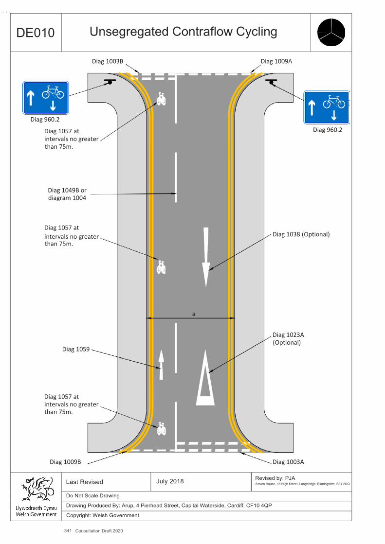
341 Consultation Draft 2020
A4
DE010 Unsegregated Contraflow Cycling
Diag 1003B Diag 1009A
Diag 960.2
Diag 1057 at Diag 960.2 intervals no greater than 75m.
Diag 1049B or diagram 1004
Diag 1057 at intervals no greater Diag 1038 (Optional) than 75m.
a
Diag 1023A (Optional)
Diag 1059
Diag 1057 at intervals no greater than 75m.
Diag 1009B Diag 1003A
Last Revised July 2018 Revised by: PJA Seven House, 18 High Street, Longbridge, Birmingham, B31 2UQ
Do Not Scale Drawing
Drawing Produced By: Arup, 4 Pierhead Street, Capital Waterside, Cardiff, CF10 4QP
Copyright: Welsh Government
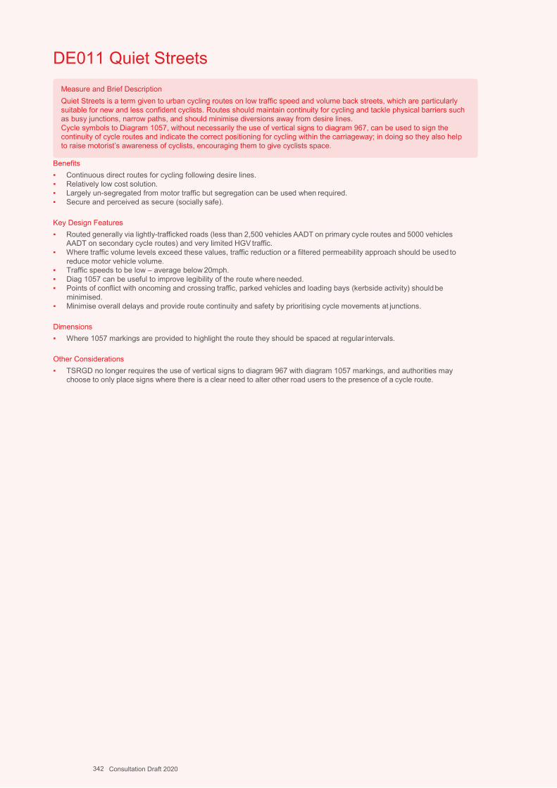
A4 296
DE011 Quiet Streets
Benefits ▪ Continuous direct routes for cycling following desire lines. ▪ Relatively low cost solution. ▪ Largely un-segregated from motor traffic but segregation can be used when required. ▪ Secure and perceived as secure (socially safe).
Key Design Features ▪ Routed generally via lightly-trafficked roads (less than 2,500 vehicles AADT on primary cycle routes and 5000 vehicles
AADT on secondary cycle routes) and very limited HGV traffic. ▪ Where traffic volume levels exceed these values, traffic reduction or a filtered permeability approach should be used to
reduce motor vehicle volume. ▪ Traffic speeds to be low – average below 20mph. ▪ Diag 1057 can be useful to improve legibility of the route where needed. ▪ Points of conflict with oncoming and crossing traffic, parked vehicles and loading bays (kerbside activity) should be
minimised. ▪ Minimise overall delays and provide route continuity and safety by prioritising cycle movements at junctions.
Dimensions ▪ Where 1057 markings are provided to highlight the route they should be spaced at regular intervals.
Other Considerations ▪ TSRGD no longer requires the use of vertical signs to diagram 967 with diagram 1057 markings, and authorities may
choose to only place signs where there is a clear need to alter other road users to the presence of a cycle route.
Measure and Brief Description Quiet Streets is a term given to urban cycling routes on low traffic speed and volume back streets, which are particularly suitable for new and less confident cyclists. Routes should maintain continuity for cycling and tackle physical barriers such as busy junctions, narrow paths, and should minimise diversions away from desire lines. Cycle symbols to Diagram 1057, without necessarily the use of vertical signs to diagram 967, can be used to sign the continuity of cycle routes and indicate the correct positioning for cycling within the carriageway; in doing so they also help to raise motorist’s awareness of cyclists, encouraging them to give cyclists space.
342 Consultation Draft 2020
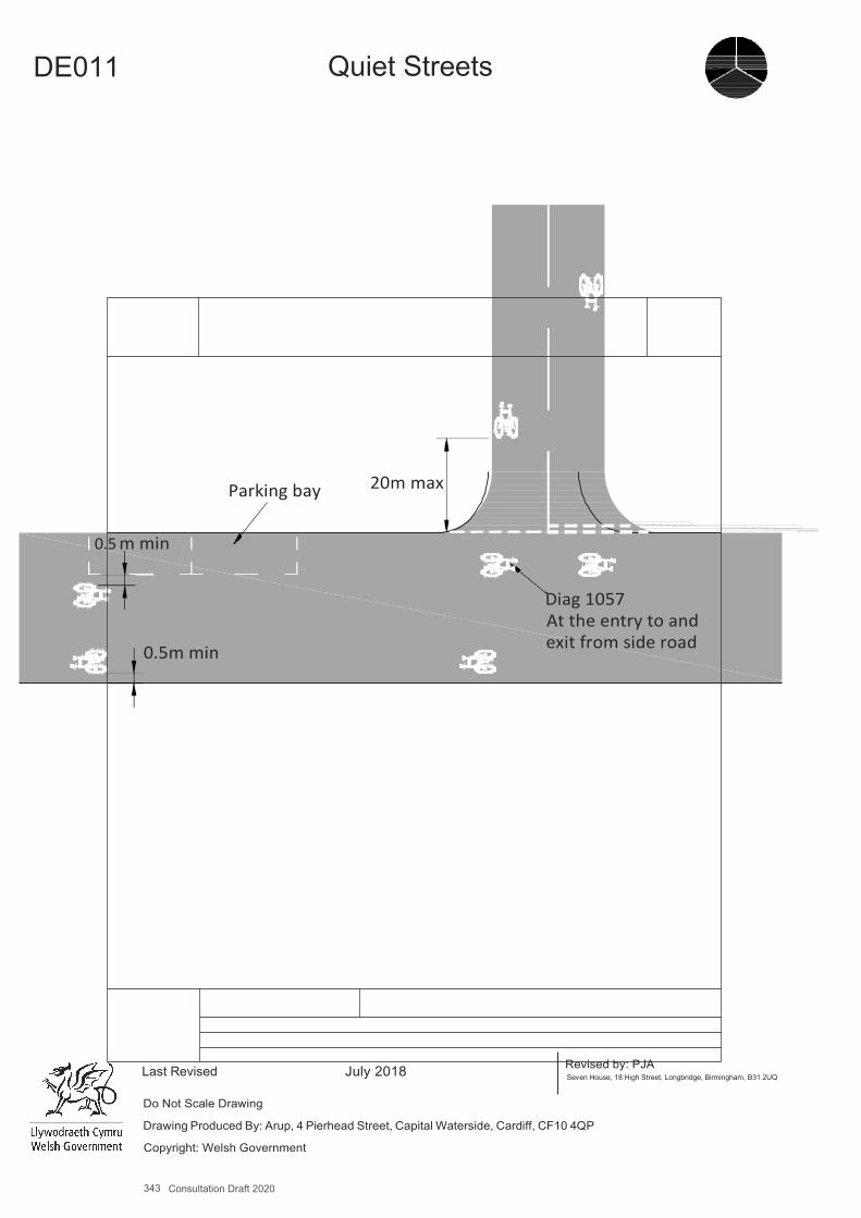
343 Consultation Draft 2020
A4
DE011 Quiet Streets
Parking bay 20m max
0.5 m min
0.5m min
Diag 1057 At the entry to and exit from side road
Last Revised July 2018 Revised by: PJA Seven House, 18 High Street, Longbridge, Birmingham, B31 2UQ
Do Not Scale Drawing
Drawing Produced By: Arup, 4 Pierhead Street, Capital Waterside, Cardiff, CF10 4QP
Copyright: Welsh Government
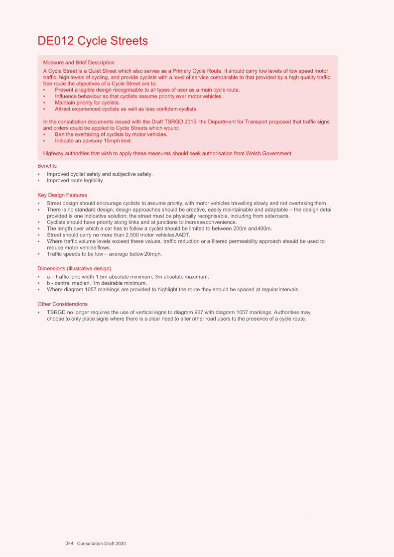
Design Guidance: Active Travel (Wales) Act 2013
298298 version 1 -
DDececemembberer 20201414
DE012 Cycle Streets
Benefits ▪ Improved cyclist safety and subjective safety. ▪ Improved route legibility.
Key Design Features ▪ Street design should encourage cyclists to assume priority, with motor vehicles travelling slowly and not overtaking them. ▪ There is no standard design; design approaches should be creative, easily maintainable and adaptable – the design detail
provided is one indicative solution; the street must be physically recognisable, including from side roads. ▪ Cyclists should have priority along links and at junctions to increase convenience. ▪ The length over which a car has to follow a cyclist should be limited to between 200m and 400m. ▪ Street should carry no more than 2,500 motor vehicles AADT. ▪ Where traffic volume levels exceed these values, traffic reduction or a filtered permeability approach should be used to
reduce motor vehicle flows. ▪ Traffic speeds to be low – average below 20mph.
Dimensions (Illustrative design) ▪ a – traffic lane width 1.5m absolute minimum, 3m absolute maximum. ▪ b - central median, 1m desirable minimum. ▪ Where diagram 1057 markings are provided to highlight the route they should be spaced at regular intervals.
Other Considerations ▪ TSRGD no longer requires the use of vertical signs to diagram 967 with diagram 1057 markings. Authorities may
choose to only place signs where there is a clear need to alter other road users to the presence of a cycle route.
-
Measure and Brief Description A Cycle Street is a Quiet Street which also serves as a Primary Cycle Route. It should carry low levels of low speed motor traffic, high levels of cycling, and provide cyclists with a level of service comparable to that provided by a high quality traffic free route the objectives of a Cycle Street are to: ▪ Present a legible design recognisable to all types of user as a main cycle route. ▪ Influence behaviour so that cyclists assume priority over motor vehicles. ▪ Maintain priority for cyclists. ▪ Attract experienced cyclists as well as less confident cyclists.
In the consultation documents issued with the Draft TSRGD 2015, the Department for Transport proposed that traffic signs and orders could be applied to Cycle Streets which would: ▪ Ban the overtaking of cyclists by motor vehicles. ▪ Indicate an advisory 15mph limit.
Highway authorities that wish to apply these measures should seek authorisation from Welsh Government.
344 Consultation Draft 2020

345 Consultation Draft 2020
A4
DE012 Cycle Streets
Diag 1057
Large Diag. 1057 At regular intervals
Footway
Cycle Lane
a
Median
b
Cycle Lane
a
Footway
Indication of waiting and loading restrictions by markings will enable civil enforcement, but will require TRO
Contrasting surface in carriageway to visibly narrow and suggest pedestrian crossing movements
Last Revised July 2018 Revised by: PJA Seven House, 18 High Street, Longbridge, Birmingham, B31 2UQ
Do Not Scale Drawing
Drawing Produced By: Arup, 4 Pierhead Street, Capital Waterside, Cardiff, CF10 4QP
Copyright: Welsh Government

Design Guidance: Active Travel (Wales) Act 2013
300300 version 1 - DDececemembberer 20201414
DE013 Mandatory Cycle Lane
Benefits ▪ For exclusive use by cyclists during hours of operation (normally at all times). ▪ Delineated by solid white line, which is less likely to be crossed by motor vehicles. ▪ Can be enforced by the Police. ▪ Reduces the potential for conflict between motor vehicles and cycles compared to an advisory lane. ▪ Highlights presence of cyclists. ▪ Reduced lane width for motor traffic likely to reduce traffic speeds.
Key Design Features ▪ Continuity of cycle lane essential. ▪ Solid white delineation line 150mm wide (Diagram 1049). ▪ Cycle symbol markings (diagram 1057) should be placed at the start of the lane and after every break, as well as at regular
intervals on long uninterrupted lengths. ▪ TRO not required for use of marking but may be used to enforce parking. ▪ Lanes should operate at all times. ▪ Waiting and loading restrictions should apply at all times.
Dimensions ▪ a - Desirable minimum 2.0m, Absolute minimum 1.5m. ▪ Cycle lane entry taper 1:10, exit taper 1:5.
Other Considerations ▪ Mandatory lanes must be discontinued at side road junctions but the use of a short length marking to diagram 1010
preserves continuity. ▪ Mandatory lanes can be continued across private accesses. ▪ Additional protection of cycle lanes can be provided using hatched road markings and traffic islands. ▪ A cyclist riding in the ‘secondary’ position will fill a 1.5m cycle lane, so if this width cannot be provided a cycle lane is unlikely
to be appropriate. ▪ Inadequate cycle lane widths may increase conflict risk because drivers do not realise that cyclists need to move away
from the kerb to avoid surface hazards. A narrow cycle lane may also give motorists (misplaced) confidence to provide less clearance while overtaking than they would in the absence of a cycle lane.
▪ Greater width should be considered on uphill cycle lanes to allow for additional lateral movement. ▪ A single uphill cycle lane is preferable to two sub-standard lanes. ▪ Cycle lanes constrain cyclists to the margin of the carriageway and so cycle-friendly gully gratings are essential. ▪ Authorities may choose to only place vertical signs to diagram 959.1 with each diagram 1057 marking where there is a clear
need to alert other road users to the presence of the mandatory lane.
Further References ▪ Department for Transport (2003) – Traffic Signs Manual Volume 3. Road Markings.
Measure and Brief Description Mandatory cycle lanes define an area of the carriageway that is reserved for cyclists and are suitable for roads where the speed limit is 30mph or less. Mandatory lanes are marked with a continuous white line (Diagram 1049) which prohibits vehicles from entering the lane during the hours of operation, which should normally be at all times. There can be exceptions, such as emergency service vehicles and access to private driveways. Parking and loading should also be prohibited through appropriate controls. Mandatory lanes are preferable to advisory lanes and should be used unless there are particular local circumstances preventing their use. Following TSRGD in 2016, mandatory lanes do not require Traffic Regulation Orders to be made.
346 Consultation Draft 2020
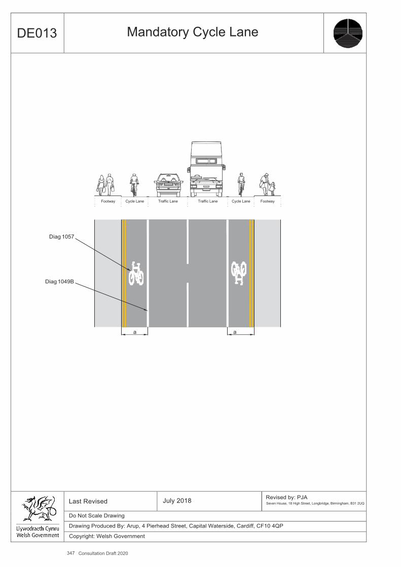
347 Consultation Draft 2020
A4
DE013 Mandatory Cycle Lane
Footway Cycle Lane Traffic Lane Traffic Lane Cycle Lane Footway
Diag 1057
Diag 1049B
a a
Last Revised July 2018 Revised by: PJA Seven House, 18 High Street, Longbridge, Birmingham, B31 2UQ
Do Not Scale Drawing
Drawing Produced By: Arup, 4 Pierhead Street, Capital Waterside, Cardiff, CF10 4QP
Copyright: Welsh Government
Design Guidance: Active Travel (Wales) Act 2013
302302 version 1 - DDececemembberer 20201414
DE014 Advisory Cycle Lane
Benefits ▪ Can be used in circumstances where a carriageway is not wide enough to permit full width mandatory cycle lanes, resulting
in occasional motor vehicles entering the cycle lane. ▪ Can be useful to indicate routes through a large or complex junction. ▪ Reduces the potential for conflict between motor vehicle andcycles. ▪ Highlights presence of cyclists. ▪ Reduced lane width for motor traffic likely to reduce traffic speeds.
Key Design Features ▪ Continuity of cycle lane essential. ▪ Bounded by broken white line 100mm wide (diagram 1004). ▪ Cycle symbol markings (diagram 1057) should be placed at the start of the lane and after every break, as well as at regular
intervals on long uninterrupted lengths. ▪ TRO not required for advisory cycle lane. ▪ Waiting and loading restrictions should apply at all times.
Dimensions ▪ a - Desirable minimum 2.0m, Absolute minimum 1.5m. ▪ Cycle lane entry taper 1:10, exit taper 1:5.
Other Considerations ▪ Where width is constrained, a wider advisory cycle lane may be preferable to a narrow mandatory one. ▪ There can be benefits in continuing advisory cycle lanes through signalled junctions. ▪ Additional protection of cycle lanes can be provided using hatched road markings and traffic islands. ▪ A cyclist riding in the ‘secondary’ position will fill a 1.5m cycle lane, so if this width cannot be provided a cycle lane is unlikely
to be appropriate. ▪ Inadequate cycle lane widths may increase conflict risk because drivers do not realise that cyclists need to move away
from the kerb to avoid surface hazards. A narrow cycle lane may also give motorists (misplaced) confidence to provide less clearance while overtaking than they would in the absence of a cycle lane.
▪ Greater width should be considered on uphill cycle lanes to allow for additional lateral movement. ▪ A single uphill cycle lane is preferable to two sub-standard lanes. ▪ Cycle lanes constrain cyclists to the margin of the carriageway and so cycle-friendly gully gratings are essential. ▪ Authorities may choose to only place vertical signs to diagram 967 with each diagram 1057 marking where there is a clear
need to alter other road users to the presence of the mandatory lane.
Further References ▪ Department for Transport (2003) – Traffic Signs Manual Volume 3. Road Markings.
-
Measure and Brief Description Advisory cycle lanes define an area of the carriageway that is intended for cyclists and are suitable for roads where the speed limit is 30mph or less. Advisory lanes are marked with a broken white line (Diagram 1004) which indicates that other vehicles should not enter unless it is safe to do so. Advisory lanes are less preferable than mandatory lanes, which should be used unless there are particular local circumstances.
348 Consultation Draft 2020
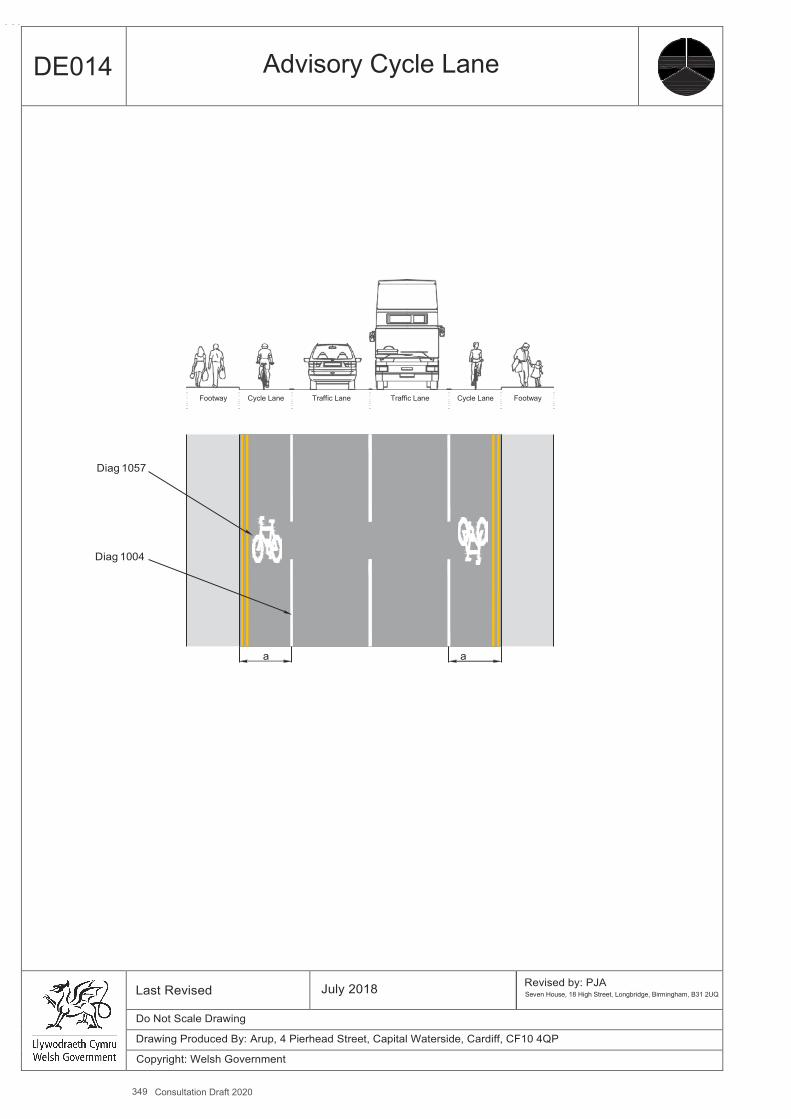
349 Consultation Draft 2020
A4
DE014 Advisory Cycle Lane
Footway Cycle Lane Traffic Lane Traffic Lane Cycle Lane Footway
Diag 1057
Diag 1004
a a
Last Revised July 2018 Revised by: PJA Seven House, 18 High Street, Longbridge, Birmingham, B31 2UQ
Do Not Scale Drawing
Drawing Produced By: Arup, 4 Pierhead Street, Capital Waterside, Cardiff, CF10 4QP
Copyright: Welsh Government
Design Guidance: Active Travel (Wales) Act 2013
304304 version 1 -
DeDeccemembberer 20201414
DE015 Cycle Lane Passing Car Parking/Loading
Benefits ▪ Prevents cyclists being hit by vehicle doors opening. ▪ Reduces the risk of cyclists having to swerve into traffic lane to avoid opening doors. ▪ Encourages good road positioning as taught in cycle training. ▪ Prevents cyclists getting trapped at the kerbside at the start of a parking bay.
Key Design Features ▪ Buffer strip between parking/loading bays and cycle lane. ▪ Hatched road markings may be used to define the buffer strip. ▪ Tapers required at approach to and at end of parking/loading bays.
Dimensions ▪ a - Desirable minimum 2m, Absolute minimum 1.5m. ▪ b - Buffer strip along parking/loading bays - desirable minimum 1m, absolute minimum 0.5m min. ▪ c – width of parking/loading bays:
for cars – min 2m wide. for vans – min 2.4m wide. for buses and HGVs min 2.8m wide (preferably 3.2m wide).
▪ d - general traffic lane should be 2.5m min width, or 3m where there are significant heavy vehicle flows. ▪ 1:10 approach taper to allow cyclists the opportunity to safely realign themselves before passing parked vehicles. ▪ 1:5 exit taper to allow cyclists the opportunity to safely realign themselves after passing parked vehicles.
Other Considerations ▪ If there is insufficient width for a cycle lane and buffer strip past car parking, consideration should be given to narrowing
traffic lanes or removal of centre line, rather than substandard facilities for cyclists. ▪ It may be possible to remove/relocate parking and introduce mandatory cycle lanes, for example if a street has adequate
off-street car parking facilities or excess provision. ▪ Where carriageway widths are narrow and parking cannot be relocated or removed all day, timed mandatory cycle lanes
could be considered for peak times. ▪ A 2.0m wide cycle lane can be reduced locally to 1.5m to allow a 0.5m wide buffer strip to be provided.
Further References ▪ Department for Transport (2003) – Traffic Signs Manual Volume 3. Road Markings.
Measure and Brief Description Kerbside vehicle parking or loading can be dangerous for cyclists, especially parking spaces with high vehicle turnover rates, since there is a significant risk to cyclists from vehicle doors being opened. It is therefore highly desirable that cycle lanes pass vehicle parking areas with a dividing strip of sufficient width (buffer strip).
350 Consultation Draft 2020

351 Consultation Draft 2020
A4
DE015 Cycle Lane Passing Car Parking / Loading
Cycle Lane passing inside of parking / loading bays
Diag 1049B Parking bay Buffer
Cycle Lane passing outside of parking / loading bays
Diag 1057 at 20m min intervals
Parking bays
Diag 1040.4 to lead into 1:5 taper beyond parking bays
Diag 1049B or 1004
Diag 1014 Diag 1004 Diag 1040.4 1:10 taper
<30m without returning Cycle Lane to kerb
Last Revised
July 2018
Revised by: PJA Seven House, 18 High Street, Longbridge, Birmingham, B31 2UQ
Do Not Scale Drawing
Drawing Produced By: Arup, 4 Pierhead Street, Capital Waterside, Cardiff, CF10 4QP
Copyright: Welsh Government
b
d
a
c
b

Design Guidance: Active Travel (Wales) Act 2013
306306 version 1 - DDececemembberer 20201414
DE016 Cycle Lane at Side Road
Benefits ▪ improves conspicuity of cyclists at conflict point. ▪ provides route continuity.
Key Design Features ▪ The use of Diagram 1010 markings is recommended in preference to advisory cycle lanes to Diagram 1004 to increase
conspicuity. ▪ Cycle symbols (Diagram 1057) may be placed in the cycle lane along the mouth of a junction. ▪ Coloured road surfacing may also be used in cycle lane to highlight the area of potential conflict. ▪ Wider cycle lanes across side roads help offer cyclists more space when cars encroach and encourage better road
positioning by cyclists.
Dimensions ▪ a – Width on approach - desirable minimum 2.0m, absolute minimum 1.5m. ▪ b - Width at side road should be at least 0.5m greater than on approaches. ▪ c - general traffic lane should be 2.5m min width, or 3m where there are significant heavy vehicle flows. ▪ Widening at side road introduced with 1:10 entry taper and 1:5 exit taper.
Other Considerations ▪ Side road entry treatments (DE39) should also be considered, which provide raised carriageway tables and reduced comer
radii at side road junctions. They help reduce turning vehicle speeds, making it safer and more accessible for cyclists passing through the junction and pedestrians crossing the side road.
▪ Entry to and from side roads should be reviewed to ensure appropriate sightlines and speeds to mitigate risks to cyclists from turning traffic.
▪ Side-road warning signs to Diagrams 962.1 or 963.1 to warn motorists and pedestrians of the presence of cyclists are generally unnecessary except for situations where contra-flow cycling is permitted.
Measure and Brief Description Cycle lanes should continue across side road junctions to ensure continuity and help improve safety. This can be achieved using a stretch of road marking 1010, where the white line is broken, since continuous mandatory lanes across side road junctions are not permitted and in preference to advisory cycle lanes to diagram 1004. It is recommended that the cycle lane width be increased at the mouth of side roads to encourage cyclists to position themselves further out from the kerb in order to increase its effectiveness and avoid conflict with vehicles nosing out of junctions.
352 Consultation Draft 2020
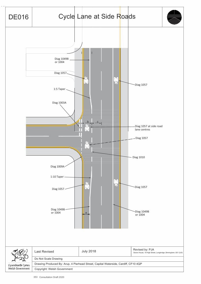
353 Consultation Draft 2020
A4
DE016 Cycle Lane at Side Roads
Diag 1049B or 1004
Diag 1057
1:5 Taper
Diag 1003A
Diag 1009A
1:10 Taper
Diag 1057
Diag 1049B or 1004
b
a
c
Diag 1057
Diag 1057 at side road lane centres
Diag 1057
Diag 1010
Diag 1057
Diag 1049B or 1004
Last Revised July 2018 Revised by: PJA Seven House, 18 High Street, Longbridge, Birmingham, B31 2UQ
Do Not Scale Drawing
Drawing Produced By: Arup, 4 Pierhead Street, Capital Waterside, Cardiff, CF10 4QP
Copyright: Welsh Government

Design Guidance: Active Travel (Wales) Act 2013
308308 version 1 - DDececemembberer 20201414
DE017 Cycle Lanes with Removal of Centre Lines
Benefits ▪ Creates sufficient width for cycle lanes of the appropriate standard. ▪ Creates a safer and more comfortable environment than sub-standard cycle lanes. ▪ Achieves speed reduction for motor vehicles. ▪ Cost-effective, may be facilitated through maintenance works. ▪ Can be politically more acceptable than other more physical, traffic calming techniques.
Key Design Features ▪ Not suitable for roads with high traffic and HGV flows. ▪ A max of 10,000 vehicles AADT is recommended, although schemes have been introduced with traffic volumes of up to
14,000 vehicles AADT. ▪ Not suitable for roads with speed limits over 30mph. ▪ Unless only light vehicles are present, advisory cycle lanes should be used so that large vehicles can use the cycle lanes to
pass one another. ▪ Requires adequate forward visibility.
Dimensions ▪ a - Desirable minimum 2.0m, Absolute minimum 1.5m. ▪ b - central general traffic lane 3m to 5.5m wide, preferably 4.1m – 4.8m. ▪ Where kerb-side parking is present, provide a buffer strip of 0.5 - 1m, or use inset parking bays.
Other Considerations ▪ If the general traffic lanes are wider than 5.5m in total, the additional space should be used to increase the width of cycle
lanes.
-
Measure and Brief Description Consideration can be given to the removal of centre lines where carriageway widths do not permit the introduction of cycle lanes of adequate width whilst retaining two general traffic lanes. In addition to increasing the width available for cyclists, the technique also has a speed reducing effect as motor traffic no longer has defined lanes in each direction. Where the need arises for on-coming motor vehicles to pass each other on a narrow carriageway, this is achieved by both drivers momentarily pulling over into their respective near-side advisory cycle lanes, having first checked to see they are clear of cyclists.
354 Consultation Draft 2020
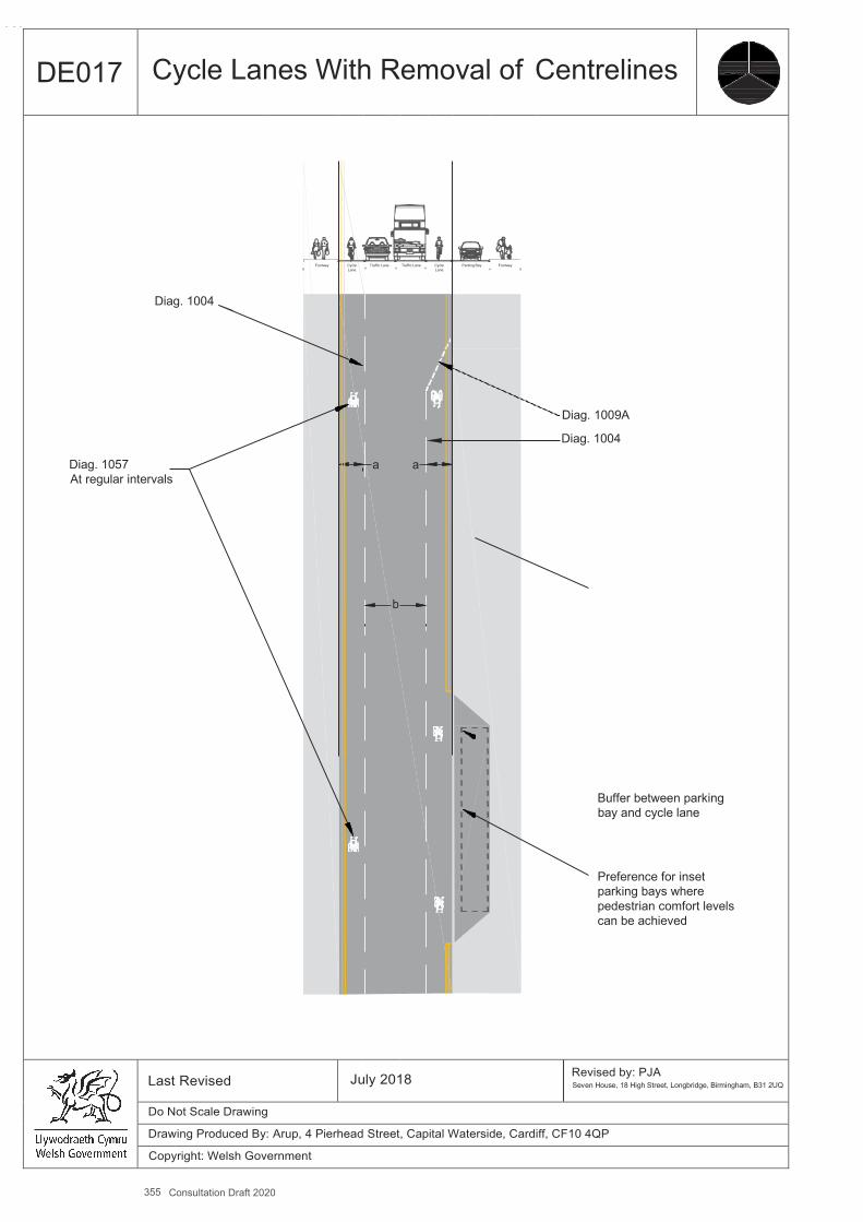
355 Consultation Draft 2020
A4
DE017 Cycle Lanes With Removal of Centrelines
Diag. 1004
Diag. 1057 At regular intervals
Footway
Cycle Lane
Traffic Lane
a
b
Traffic Lane
a
Cycle Lane
Parking Bay
Footway
Diag. 1009A
Diag. 1004
Buffer between parking bay and cycle lane
Preference for inset parking bays where pedestrian comfort levels can be achieved
Last Revised July 2018 Revised by: PJA Seven House, 18 High Street, Longbridge, Birmingham, B31 2UQ
Do Not Scale Drawing
Drawing Produced By: Arup, 4 Pierhead Street, Capital Waterside, Cardiff, CF10 4QP
Copyright: Welsh Government

Design Guidance: Active Travel (Wales) Act 2013
310310 version 1 - DDececemembberer 20201414
DE018 Cycle Lane with Light Segregation
Benefits ▪ Increase cyclist comfort and safety levels, as well as subjective safety. ▪ Can be used on roads with speed limits of up to 30mph. ▪ Physical features deter motorists from encroaching into lane. ▪ Cyclists can manoeuvre in and out of the lane to carry out right turns and for access ▪ Low installation cost. ▪ Easily installed to existing cycle lanes. ▪ Lane widths can be easily adapted to suit future conditions, such as increased usage. ▪ Can also be used for contra-flow lanes and for two way cycling. ▪ Avoids the need for drainage works.
Key Design Features ▪ Used in combination with a mandatory cycle lane (diagram 1049). ▪ Advisory cycle lane (diagram 1004) should not be used, as a key design principle is that motor vehicles should not cross
light segregation. ▪ Physical features should be placed on the left-hand side of the cycle lane marking so that the marking can clearly be seen
by drivers. ▪ Careful consideration is needed for the design of the physical feature – they need to be conspicuous and robust, but not
mimic a road marking or sign. ▪ Low features should have curved or sloped faces to minimise the hazard for motor vehicles. ▪ Continuity should be provided at bus stops.
Dimensions ▪ a - Desirable minimum 2.0m, Absolute minimum 1.5m. ▪ Where cycle flows are heavy (over 150 cyclists in the peak hour) and frequent overtaking occurs, widths should be
increased to 2.5m. ▪ b - Segregation features to be spaced at 2.5-10m intervals, or as recommended by the product manufacturer.
Other Considerations ▪ If using bollards consideration should be given for illumination or reflective strips.
Measure and Brief Description The degree of separation provided by a mandatory cycle lane may be reinforced by ‘light segregation’ from the main carriageway, i.e. intermittent low level physical features such as planters, wands (retroreflective self-righting bollards) or proprietary raised features which may be constructed from rubber, PVC or concrete. The fact that the obstacles are intermittent allows cyclists to manoeuvre between the cycle lane and the carriageway as necessary, avoids any impact on drainage and means that the design is cost effective and flexible.
356 Consultation Draft 2020
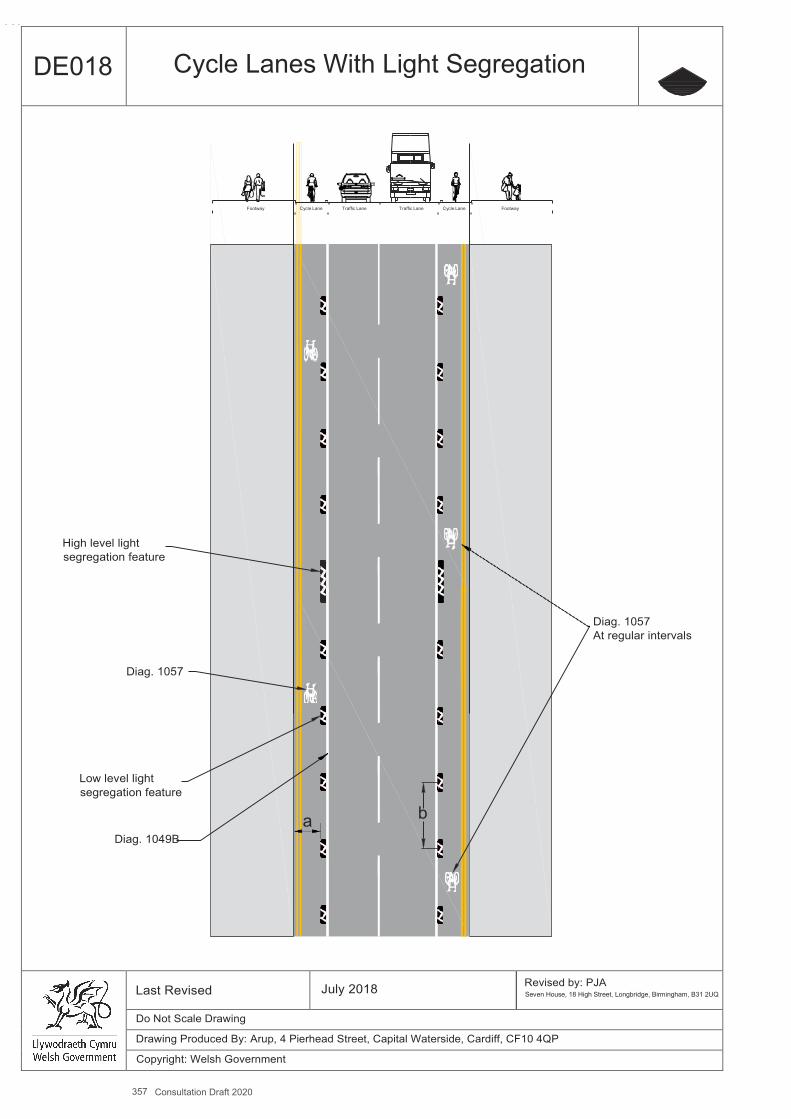
357 Consultation Draft 2020
A4
DE018 Cycle Lanes With Light Segregation
Footway Cycle Lane Traffic Lane Traffic Lane Cycle Lane Footway
High level light segregation feature
Diag. 1057 At regular intervals
Diag. 1057
Low level light segregation feature
a b Diag. 1049B
Last Revised July 2018 Revised by: PJA Seven House, 18 High Street, Longbridge, Birmingham, B31 2UQ
Do Not Scale Drawing
Drawing Produced By: Arup, 4 Pierhead Street, Capital Waterside, Cardiff, CF10 4QP
Copyright: Welsh Government

DE019 Cycle Lane with Light Segregation at Side Road Benefits ▪ improves conspicuity of cyclists at conflict point. ▪ provides route continuity.
Key Design Features ▪ Light segregation feature does not continue across side road. ▪ The use of Diagram 1010 markings is recommended in preference to advisory cycle lanes to Diagram 1004 to increase
conspicuity. ▪ Cycle symbols (Diagram 1057 TSRGD) may be placed in the cycle lane along the mouth of a junction. ▪ Coloured road surfacing may also be used in cycle lane to highlight the area of potential conflict.
Dimensions ▪ a – Width on approach - desirable minimum 2m, absolute minimum 1.5m. ▪ Should be a minimum of 2m wide across side road. ▪ Segregation features to be spaced at 2.5-10m intervals. ▪ Segregation to cease no more than 5m from junction, depending on swept path requirements.
Other Considerations ▪ Side road entry treatments (DE39) should also be considered, which provide raised carriageway tables and reduced comer
radii at side road junctions. They help reduce turning vehicle speeds, making it safer and more accessible for cyclists passing through the junction and pedestrians crossing the side road.
▪ Entry to and from side roads should be reviewed to ensure appropriate sightlines and speeds to mitigate risks to cyclists from turning traffic.
▪ Side-road warning signs to Diagrams 962.1 or 963.1 to warn motorists and pedestrians respectively are generally unnecessary except for situations where contra-flow cycling is permitted.
▪ Widening of the cycle lane at the junction can also be considered.
-
358 Consultation Draft 2020
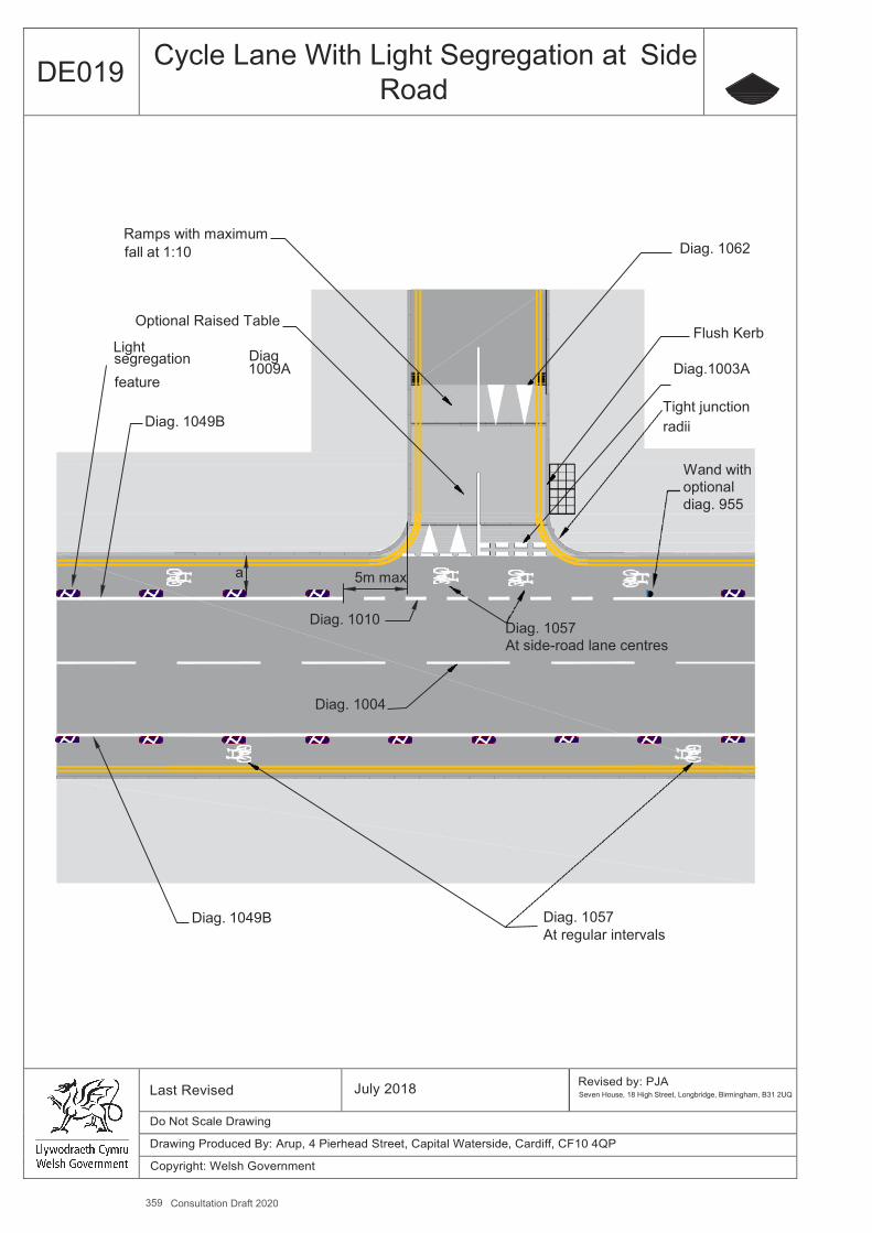
359 Consultation Draft 2020
A4
DE019 Cycle Lane With Light Segregation at Side Road
Ramps with maximum fall at 1:10 Diag. 1062
Optional Raised Table Flush Kerb
Light Diag segregation
1009A Diag.1003A feature
Tight junction Diag. 1049B radii
Wand with optional diag. 955
a 5m max
Diag. 1010 Diag. 1057
At side-road lane centres
Diag. 1004
Diag. 1049B Diag. 1057 At regular intervals
Last Revised July 2018 Revised by: PJA Seven House, 18 High Street, Longbridge, Birmingham, B31 2UQ
Do Not Scale Drawing
Drawing Produced By: Arup, 4 Pierhead Street, Capital Waterside, Cardiff, CF10 4QP
Copyright: Welsh Government

A4 314
DE020 Car Parking/Loading with Light Segregation
Benefits ▪ Provides cyclists with additional protection from moving traffic. ▪ Prevents parked cars causing obstruction to cycle lanes/tracks. ▪ Reduces likelihood and severity of cyclists being hit by vehicle doors opening. ▪ Prevents cyclists getting trapped at the start of parking bay.
Key Design Features ▪ Car parking located on the carriageway side of the cycle lane/track. ▪ Buffer strip to be provided between the edge of the cycle track and the parking/loading spaces where possible. ▪ Car parking/loading to be prohibited on the approach to side roads/accesses, so approaching cyclists are clearly visible to
traffic coming out of the side road/access.
Dimensions ▪ a - Desirable minimum 2.0m, Absolute minimum 1.5m. ▪ b - Preferably also provide buffer strip of width 0.5m. ▪ Segregation features to be spaced at 2.5-10.0m intervals.
Other Considerations ▪ A 2.0m wide cycle track can be reduced locally to 1.5m to allow a 0.5m wide dividing strip to be provided.
-
Measure and Brief Description Car parking/loading may be provided on the carriageway side of cycle lanes with light segregation, preferably with a buffer strip between the edge of the lane and the car parking/loading. Parking/loading should be prohibited in the vicinity of side road junctions and accesses so as to maintain adequate intervisibility. This detail can also be applied to hybrid cycle tracks.
360 Consultation Draft 2020

361 Consultation Draft 2020
A4
DE020 Car parking/Loading with Light Segregation
High profile feature (e.g. wand) placed along parking bay
Light segregation feature (or half height kerb if stepped track)
a
b
Min 1:5 taper
Diag. 1040.4
Diag. 1049B
Diag. 1057 At regular intervals
Car Parking Bay
Min 1:5 taper
Last Revised July 2018 Revised by: PJA Seven House, 18 High Street, Longbridge, Birmingham, B31 2UQ
Do Not Scale Drawing
Drawing Produced By: Arup, 4 Pierhead Street, Capital Waterside, Cardiff, CF10 4QP
Copyright: Welsh Government
A4 316
DE021 Stepped Cycle Track
Benefits ▪ Increase cyclist comfort and safety levels, as well as subjective safety. ▪ Can be used on roads with speed limits of up to 30mph. ▪ Level difference helps deter motorists from straying into cycle lane. ▪ Priority for cyclists over accesses to properties and side roads is maintained. ▪ Can reduce the amount of traffic signs and markings compared with mandatory cycle lanes. ▪ No TRO is required although this would be necessary for parking restrictions. ▪ Can reduce conflict between cyclists and pedestrians compared with shared use paths.
Key Design Features ▪ Hybrid cycle tracks operate one way, in the same direction as motor traffic flow. ▪ Space can be taken from footway or preferably carriageway to create the track. ▪ Lowered to merge with the carriageway at junctions or other areas where cyclists need to access the general traffic lanes. ▪ Continuity should be provided at bus stops. ▪ Hybrid tracks at side roads retain priority for cyclists.
Dimensions ▪ a - Desirable minimum 2.0m, Absolute minimum 1.5m. ▪ Where cycle flows are heavy (over 150 cyclists in the peak hour) and frequent overtaking occurs, widths should be
increased to 2.5m. ▪ Minimum kerb upstands should generally be 50mm on the carriageway side, and 25mm on the footway side. ▪ Lamp columns, sign posts, etc should be placed 0.5m from any hybrid cycle lane.
Other Considerations ▪ New drainage facilities will need to be introduced into the narrowed carriageway while existing grates will need to be raised
to cycle track level. Cycle friendly drainage grates should be used for both. ▪ Can be used as part of centre line removal projects. ▪ There is no particular requirement to sign hybrid tracks (or use coloured surfacing). In many cases, the kerb upstand itself
will suffice to deter motor vehicles from entering. However, the use of a mandatory lane placed on the carriageway side of the kerb could be considered if encroachment by motor vehicles (including parking) becomes a problem.
Measure and Brief Description Hybrid cycle tracks have a surface raised above the carriageway but are below the level of the footway. They keep cyclists close to other traffic but provide more separation from it than a cycle lane or light segregation does. Cyclists can enter and leave the cycle track relatively easily where lowered kerbs or fillets are provided but the presence of a raised kerb edge along most of the length deters encroachment by motor vehicles.
362 Consultation Draft 2020
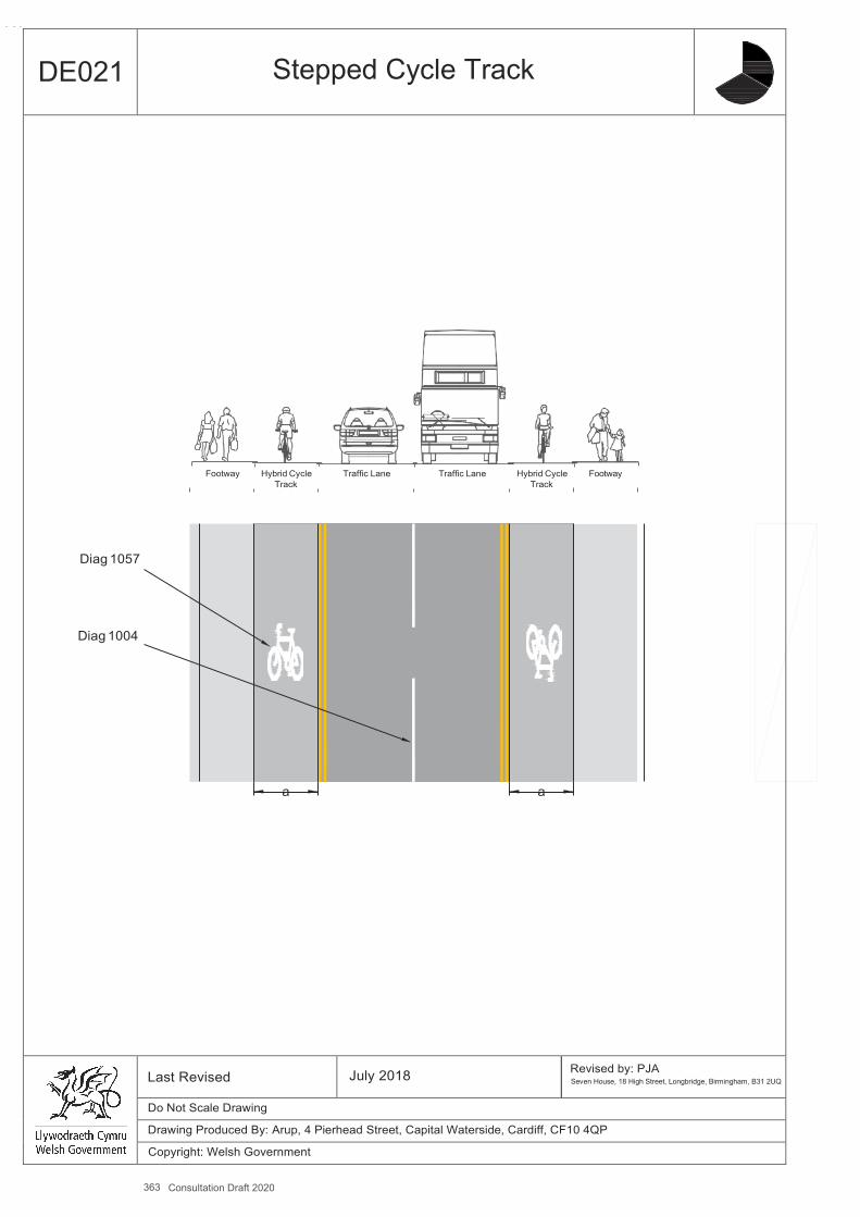
363 Consultation Draft 2020
A4
DE021 Stepped Cycle Track
Footway Hybrid Cycle Traffic Lane Traffic Lane Hybrid Cycle Footway
Track Track
Diag 1057
Diag 1004
a a
Last Revised July 2018 Revised by: PJA Seven House, 18 High Street, Longbridge, Birmingham, B31 2UQ
Do Not Scale Drawing
Drawing Produced By: Arup, 4 Pierhead Street, Capital Waterside, Cardiff, CF10 4QP
Copyright: Welsh Government
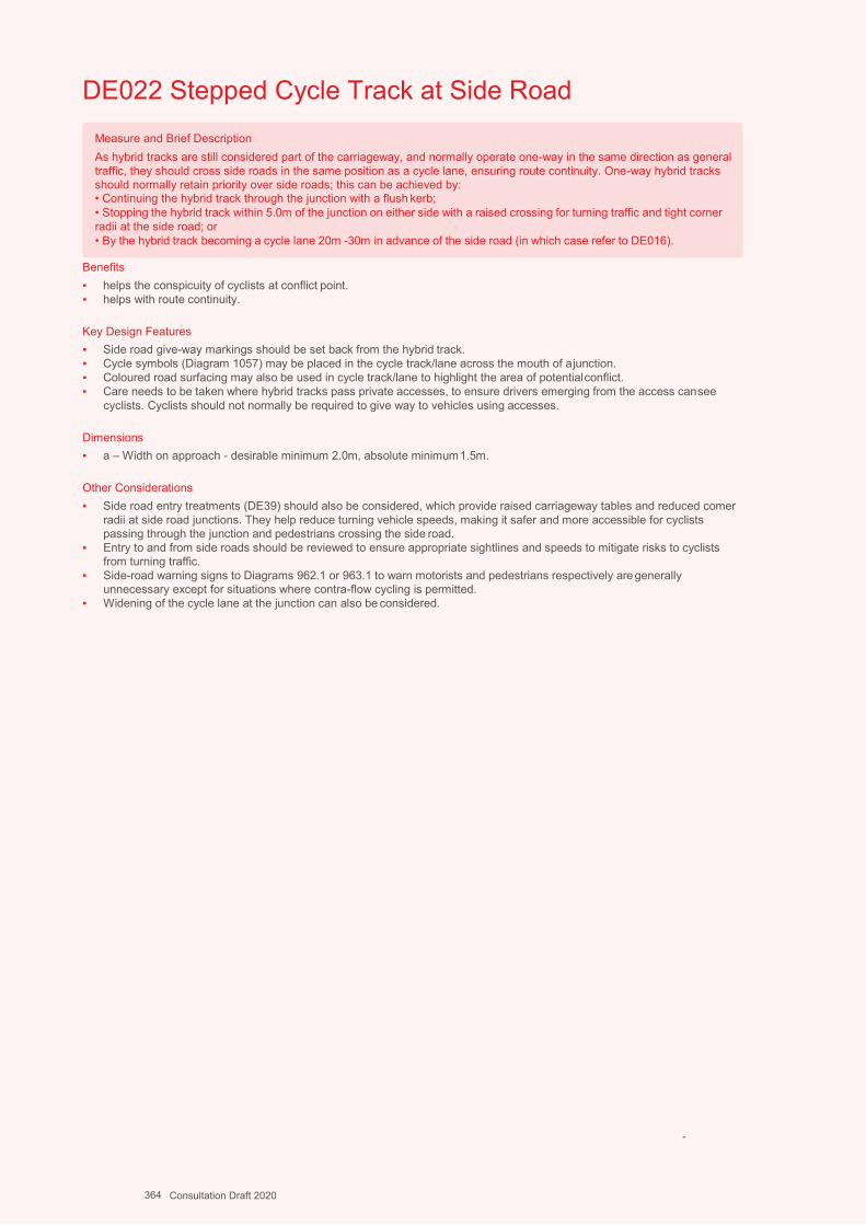
A4 318
DE022 Stepped Cycle Track at Side Road
Benefits ▪ helps the conspicuity of cyclists at conflict point. ▪ helps with route continuity.
Key Design Features ▪ Side road give-way markings should be set back from the hybrid track. ▪ Cycle symbols (Diagram 1057) may be placed in the cycle track/lane across the mouth of a junction. ▪ Coloured road surfacing may also be used in cycle track/lane to highlight the area of potential conflict. ▪ Care needs to be taken where hybrid tracks pass private accesses, to ensure drivers emerging from the access can see
cyclists. Cyclists should not normally be required to give way to vehicles using accesses.
Dimensions ▪ a – Width on approach - desirable minimum 2.0m, absolute minimum 1.5m.
Other Considerations ▪ Side road entry treatments (DE39) should also be considered, which provide raised carriageway tables and reduced comer
radii at side road junctions. They help reduce turning vehicle speeds, making it safer and more accessible for cyclists passing through the junction and pedestrians crossing the side road.
▪ Entry to and from side roads should be reviewed to ensure appropriate sightlines and speeds to mitigate risks to cyclists from turning traffic.
▪ Side-road warning signs to Diagrams 962.1 or 963.1 to warn motorists and pedestrians respectively are generally unnecessary except for situations where contra-flow cycling is permitted.
▪ Widening of the cycle lane at the junction can also be considered.
-
Measure and Brief Description As hybrid tracks are still considered part of the carriageway, and normally operate one-way in the same direction as general traffic, they should cross side roads in the same position as a cycle lane, ensuring route continuity. One-way hybrid tracks should normally retain priority over side roads; this can be achieved by: • Continuing the hybrid track through the junction with a flush kerb; • Stopping the hybrid track within 5.0m of the junction on either side with a raised crossing for turning traffic and tight corner radii at the side road; or • By the hybrid track becoming a cycle lane 20m -30m in advance of the side road (in which case refer to DE016).
364 Consultation Draft 2020
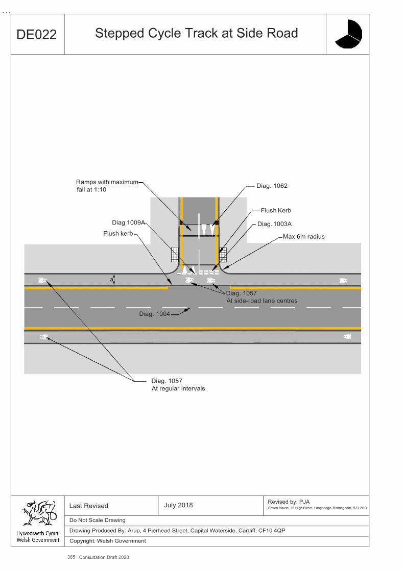
365 Consultation Draft 2020
A4
DE022 Stepped Cycle Track at Side Road
Ramps with maximum Diag. 1062 fall at 1:10
Flush Kerb
Diag 1009A Diag. 1003A Flush kerb Max 6m radius
a
Diag. 1057 At side-road lane centres
Diag. 1004
Diag. 1057 At regular intervals
Last Revised July 2018 Revised by: PJA Seven House, 18 High Street, Longbridge, Birmingham, B31 2UQ
Do Not Scale Drawing
Drawing Produced By: Arup, 4 Pierhead Street, Capital Waterside, Cardiff, CF10 4QP
Copyright: Welsh Government
L
DE023 Cycle Track Alongside Road, Separated From Pedestrians
Benefits ▪ Provides routes which are free from conflict with motor traffic. ▪ Segregated paths allow each group to move at their own desired pace and improve comfort and subjective safety.
Key Design Features ▪ The cycle track should normally be located between carriageway and footway. ▪ Footways and cycle tracks should be continuous across private accesses. ▪ Pedestrians require regular crossing points with flush kerbs between the cycle track and the carriageway; tactile paving
should be provided. ▪ Cycle tracks should not deflect more than 45º and changes in height should be avoided. ▪ Machine-laid black bituminous surfacing should be used as it will make cycle journeys safer, more comfortable and helps
distinguish cycle tracks from adjacent footways surfaced by paviours or slabs. ▪ Lamp columns and other street furniture should not be placed in cycle tracks. ▪ Centre lines should be marked on two-way cycle tracks.
Dimensions ▪ a - Cycle track width should be sufficient to accommodate the forecast level of use with a minimum of:
Absolute minimum 2.5m, where the peak hour cycle flow is less than 50/hr; Desirable minimum 3m, where it is 50-250/hr, 4m for cycle flows over 250/hr.
▪ Cycle tracks should include additional width where they are bounded by vertical features. Additional width required is: Kerb up to 150mm high: add 200mm. Vertical feature 150-600mm high: add 250mm. Vertical feature above 600mm high: add 500mm.
▪ b - In addition to the path width above, a margin strip separating the cycle track from the carriageway is recommended: Desirable minimum 0.5m with speed limits of 30mph Desirable minimum 1.5m with speeds limits of 40mph or above.
▪ c - The width of the footway should reflect the level and type of use, based on level of service, Desirable minimum 2.0m width, increasing to 3.5m width where there is frequent use by groups. 1.5m may be acceptable over short lengths – see DE001.
▪ Verges separating pedestrian and cycle routes should be a minimum of 1m wide.
Other Considerations ▪ Generally cycle tracks alongside the carriageway will either be two-way, usually on one side of the road, or one-way on both
sides of the road. Historically most cycle tracks in the UK have been built as two-way, but this can present safety problems at junctions.
▪ Care needs to be taken where a cycle track passes private accesses, to ensure drivers emerging from the access cansee cyclists.
▪ Two-way tracks are therefore best suited to routes that have few side road junctions and accesses. ▪ Use of white lining to provide a buffer between the cycle track and carriageway is not recommended in unlit areas, as this
could be misinterpreted as marking the edge of carriageway by passing motorists, who are then at risk of striking the kerb and losing control.
▪ Upright signs to indicate cycle track should preferably be located in the verge or footway.
Measure and Brief Description Where traffic volumes and/or speeds are too high for cycle lanes, light segregation or hybrid tracks, physical separation from motor traffic may be appropriate to provide cyclists with safe and comfortable space, through the provision of segregated cycle tracks. Segregated cycle tracks should be of adequate width, comfortable, continuous and link into surrounding cycling routes. Preferably they will be provided through reallocation of road space from the carriageway; in most urban locations the conversion of footways to segregated shared use should be the last resort. Physical segregation from pedestrians is generally preferred provided widths are adequate and this can be achieved through a level difference or verge. Barriers between cycle tracks and footways are not desirable since they limit the effective width of the paths and are a particular hazard to cyclists. Segregation using only simple white lines (Diag 1049) (which are not detectable by blind users) or a raised white line delineator (Diag 1049.1), is an option but it is rarely respected by pedestrians (who have the legal right to use the cycle track) in practice, unless cycle flows are high or there is generous width, and should therefore be avoided.
366 Consultation Draft 2020
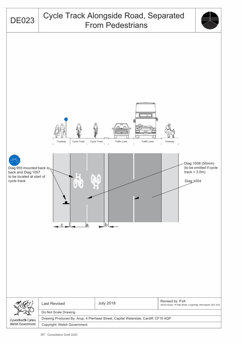
367 Consultation Draft 2020
A4
DE023 Cycle Track Alongside Road, Separated From Pedestrians
Diag 955 mounted back back and Diag 1057 to be located at start of cycle track
to
Footway
c
Cycle Track
a
Cycle Track Traffic Lane Traffic Lane
b
Footway
Diag 1008 (50mm) (to be omitted if cycle track < 3.0m)
Diag 1004
Last Revised July 2018 Revised by: PJA Seven House, 18 High Street, Longbridge, Birmingham, B31 2UQ
Do Not Scale Drawing
Drawing Produced By: Arup, 4 Pierhead Street, Capital Waterside, Cardiff, CF10 4QP
Copyright: Welsh Government
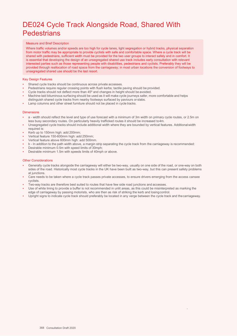
Design Guidance: Active Travel (Wales) Act 2013
322322 version 1 - DDececemembberer 20201414
DE024 Cycle Track Alongside Road, Shared With Pedestrians
Key Design Features ▪ Shared cycle tracks should be continuous across private accesses. ▪ Pedestrians require regular crossing points with flush kerbs; tactile paving should be provided. ▪ Cycle tracks should not deflect more than 45º and changes in height should be avoided. ▪ Machine-laid bituminous surfacing should be used as it will make cycle journeys safer, more comfortable and helps
distinguish shared cycle tracks from nearby footways surfaced by paviours or slabs. ▪ Lamp columns and other street furniture should not be placed in cycle tracks.
Dimensions ▪ a - width should reflect the level and type of use forecast with a minimum of 3m width on primary cycle routes, or 2.5m on
less busy secondary routes. On particularly heavily trafficked routes it should be increased to 4m. ▪ Unsegregated cycle tracks should include additional width where they are bounded by vertical features. Additional width
required is: ▪ Kerb up to 150mm high: add 200mm; ▪ Vertical feature 150-600mm high: add 250mm; ▪ Vertical feature above 600mm high: add 500mm. ▪ b - In addition to the path width above, a margin strip separating the cycle track from the carriageway is recommended: ▪ Desirable minimum 0.5m with speed limits of 30mph; ▪ Desirable minimum 1.5m with speeds limits of 40mph or above.
Other Considerations ▪ Generally cycle tracks alongside the carriageway will either be two-way, usually on one side of the road, or one-way on both
sides of the road. Historically most cycle tracks in the UK have been built as two-way, but this can present safety problems at junctions.
▪ Care needs to be taken where a cycle track passes private accesses, to ensure drivers emerging from the access cansee cyclists.
▪ Two-way tracks are therefore best suited to routes that have few side road junctions and accesses. ▪ Use of white lining to provide a buffer is not recommended in unlit areas, as this could be misinterpreted as marking the
edge of carriageway by passing motorists, who are then as risk of striking the kerb and losing control. ▪ Upright signs to indicate cycle track should preferably be located in any verge between the cycle track and the carriageway.
-
Measure and Brief Description Where traffic volumes and/or speeds are too high for cycle lanes, light segregation or hybrid tracks, physical separation from motor traffic may be appropriate to provide cyclists with safe and comfortable space. Where a cycle track will be shared with pedestrians, sufficient width must be provided for the two user groups to interact safely and in comfort. It is essential that developing the design of an unsegregated shared use track includes early consultation with relevant interested parties such as those representing people with disabilities, pedestrians and cyclists. Preferably they will be provided through reallocation of road space from the carriageway; in most urban locations the conversion of footways to unsegregated shared use should be the last resort.
368 Consultation Draft 2020
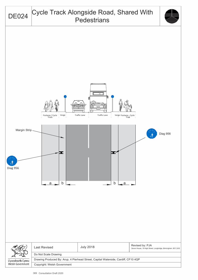
369 Consultation Draft 2020
A4
DE024 Cycle Track Alongside Road, Shared With Pedestrians
Footway / Cycle Track
Margin Strip
Diag 956
a
Verge
b
Traffic Lane Traffic Lane Verge Footway / Trac
b a
Cycle
k
Diag
956
Last Revised July 2018 Revised by: PJA Seven House, 18 High Street, Longbridge, Birmingham, B31 2UQ
Do Not Scale Drawing
Drawing Produced By: Arup, 4 Pierhead Street, Capital Waterside, Cardiff, CF10 4QP
Copyright: Welsh Government
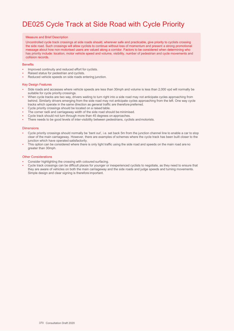
Design Guidance: Active Travel (Wales) Act 2013
324324 version 1 -
DDececemembberer 20201414
DE025 Cycle Track at Side Road with Cycle Priority
Benefits ▪ Improved continuity and reduced effort for cyclists. ▪ Raised status for pedestrian and cyclists. ▪ Reduced vehicle speeds on side roads entering junction.
Key Design Features ▪ Side roads and accesses where vehicle speeds are less than 30mph and volume is less than 2,000 vpd will normally be
suitable for cycle priority crossings. ▪ When cycle tracks are two way, drivers waiting to turn right into a side road may not anticipate cycles approaching from
behind. Similarly drivers emerging from the side road may not anticipate cycles approaching from the left. One way cycle tracks which operate in the same direction as general traffic are therefore preferred.
▪ Cycle priority crossings should be located on a raised table. ▪ The corner radii and carriageway width of the side road should be minimised. ▪ Cycle track should not turn through more than 45 degrees on approaches. ▪ There needs to be good levels of inter-visibility between pedestrians, cyclists and motorists.
Dimensions ▪ Cycle priority crossings should normally be ‘bent out’, i.e. set back 5m from the junction channel line to enable a car to stop
clear of the main carriageway. However, there are examples of schemes where the cycle track has been built closer to the junction which have operated satisfactorily.
▪ This option can be considered where there is only light traffic using the side road and speeds on the main road are no greater than 30mph.
Other Considerations ▪ Consider highlighting the crossing with coloured surfacing. ▪ Cycle track crossings can be difficult places for younger or inexperienced cyclists to negotiate, as they need to ensure that
they are aware of vehicles on both the main carriageway and the side roads and judge speeds and turning movements. Simple design and clear signing is therefore important.
Measure and Brief Description Uncontrolled cycle track crossings at side roads should, wherever safe and practicable, give priority to cyclists crossing the side road. Such crossings will allow cyclists to continue without loss of momentum and present a strong promotional message about how non-motorised users are valued along a corridor. Factors to be considered when determining who has priority include: location, motor vehicle speed and volume, visibility, number of pedestrian and cycle movements and collision records.
370 Consultation Draft 2020
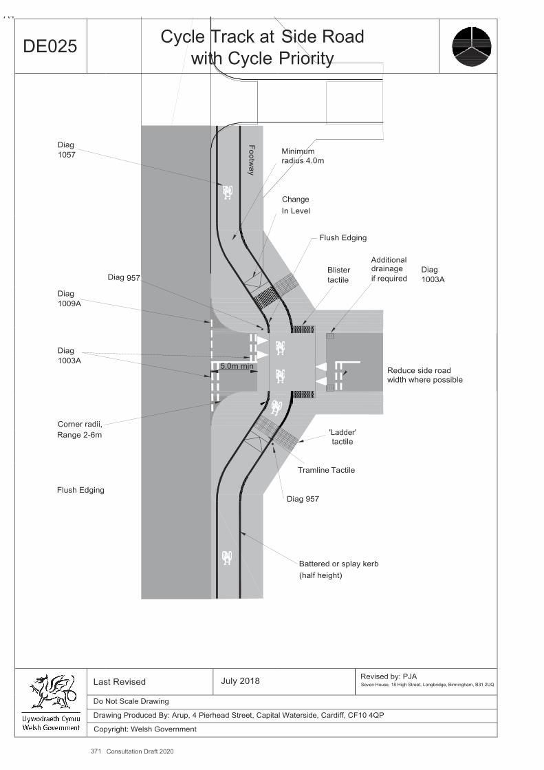
371 Consultation Draft 2020
A4
Footway
DE025 Cycle Track at with Cycle
Side Road Priority
Diag
Minimum radius 4.0m
Change In Level
Flush Edging
Additional
Blister drainage Diag tactile if required 1003A
Reduce side road width where possible
'Ladder' tactile
Tramline Tactile
Diag 957
Battered or splay kerb (half height)
1057
Diag 957
Diag 1009A
Diag
1003A 5.0m min
Corner radii,
Range 2-6m
Flush Edging
Last Revised July 2018 Revised by: PJA Seven House, 18 High Street, Longbridge, Birmingham, B31 2UQ
Do Not Scale Drawing
Drawing Produced By: Arup, 4 Pierhead Street, Capital Waterside, Cardiff, CF10 4QP
Copyright: Welsh Government
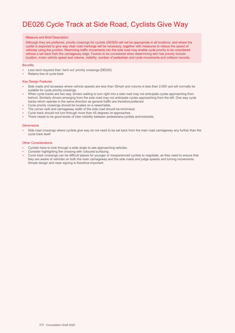
Design Guidance: Active Travel (Wales) Act 2013
326326 version 1 - DDececemembberer 20201414
DE026 Cycle Track at Side Road, Cyclists Give Way
Benefits ▪ Less land required than ‘bent out’ priority crossings (DE025) ▪ Retains line of cycle track
Key Design Features ▪ Side roads and accesses where vehicle speeds are less than 30mph and volume is less than 2,000 vpd will normally be
suitable for cycle priority crossings. ▪ When cycle tracks are two way, drivers waiting to turn right into a side road may not anticipate cycles approaching from
behind. Similarly drivers emerging from the side road may not anticipate cycles approaching from the left. One way cycle tracks which operate in the same direction as general traffic are therefore preferred.
▪ Cycle priority crossings should be located on a raised table. ▪ The corner radii and carriageway width of the side road should be minimised. ▪ Cycle track should not turn through more than 45 degrees on approaches. ▪ There needs to be good levels of inter-visibility between pedestrians,cyclists and motorists.
Dimensions ▪ Side road crossings where cyclists give way do not need to be set back from the main road carriageway any further than the
cycle track itself.
Other Considerations ▪ Cyclists have to look through a wide angle to see approaching vehicles. ▪ Consider highlighting the crossing with coloured surfacing. ▪ Cycle track crossings can be difficult places for younger or inexperienced cyclists to negotiate, as they need to ensure that
they are aware of vehicles on both the main carriageway and the side roads and judge speeds and turning movements. Simple design and clear signing is therefore important.
Measure and Brief Description Although they are preferred, priority crossings for cyclists (DE025) will not be appropriate in all locations, and where the cyclist is expected to give way clear road markings will be necessary, together with measures to reduce the speed of vehicles using the junction. Restricting traffic movements into the side road may enable cycle priority to be considered without a set back from the carriageway edge. Factors to be considered when determining who has priority include: location, motor vehicle speed and volume, visibility, number of pedestrian and cycle movements and collision records.
372 Consultation Draft 2020
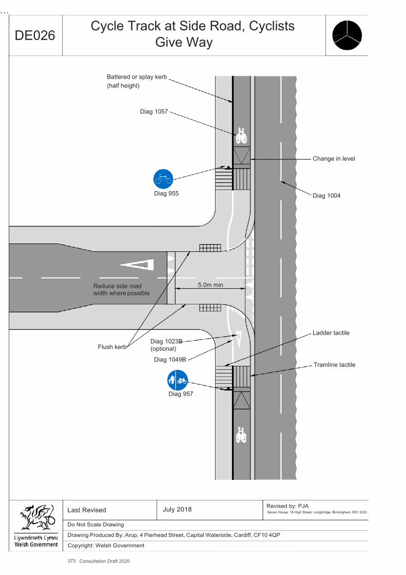
373 Consultation Draft 2020
A4
DE026 Cycle Track at Side Road, Cyclists
Give Way
Battered or splay kerb (half height)
Diag 1057
Change in level
Diag 955 Diag 1004
Reduce side road width where possible
5.0m min
Flush kerb
Diag 1023B (optional)
Diag 1049B
Ladder tactile
Tramline tactile
Diag 957
Last Revised July 2018 Revised by: PJA Seven House, 18 High Street, Longbridge, Birmingham, B31 2UQ
Do Not Scale Drawing
Drawing Produced By: Arup, 4 Pierhead Street, Capital Waterside, Cardiff, CF10 4QP
Copyright: Welsh Government
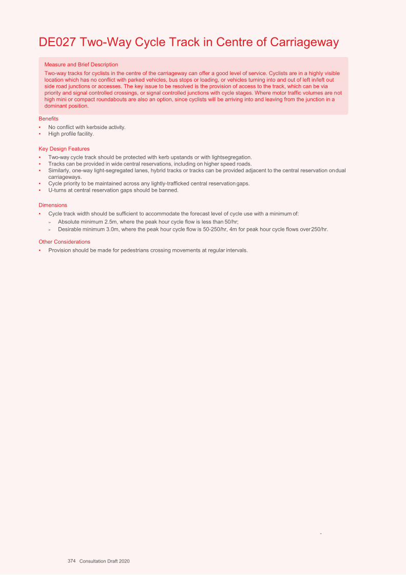
Design Guidance: Active Travel (Wales) Act 2013
328328 version 1 - DDececemembberer 20201414
DE027 Two-Way Cycle Track in Centre of Carriageway
Benefits ▪ No conflict with kerbside activity. ▪ High profile facility.
Key Design Features ▪ Two-way cycle track should be protected with kerb upstands or with lightsegregation. ▪ Tracks can be provided in wide central reservations, including on higher speed roads. ▪ Similarly, one-way light-segregated lanes, hybrid tracks or tracks can be provided adjacent to the central reservation on dual
carriageways. ▪ Cycle priority to be maintained across any lightly-trafficked central reservation gaps. ▪ U-turns at central reservation gaps should be banned.
Dimensions ▪ Cycle track width should be sufficient to accommodate the forecast level of cycle use with a minimum of:
Absolute minimum 2.5m, where the peak hour cycle flow is less than 50/hr; Desirable minimum 3.0m, where the peak hour cycle flow is 50-250/hr, 4m for peak hour cycle flows over 250/hr.
Other Considerations ▪ Provision should be made for pedestrians crossing movements at regular intervals.
-
Measure and Brief Description Two-way tracks for cyclists in the centre of the carriageway can offer a good level of service. Cyclists are in a highly visible location which has no conflict with parked vehicles, bus stops or loading, or vehicles turning into and out of left in/left out side road junctions or accesses. The key issue to be resolved is the provision of access to the track, which can be via priority and signal controlled crossings, or signal controlled junctions with cycle stages. Where motor traffic volumes are not high mini or compact roundabouts are also an option, since cyclists will be arriving into and leaving from the junction in a dominant position.
374 Consultation Draft 2020
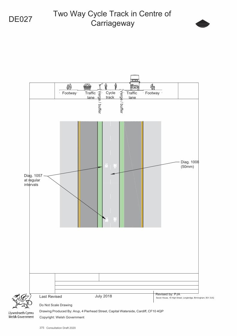
375 Consultation Draft 2020
A4
DE027 Two Way Cycle Track in Centre of
Carriageway
Footway Traffic lane
Cycle track
Traffic lane
Footway
Diag. 1008 (50mm)
Diag. 1057 at regular intervals
Last Revised
July 2018
Revised by: PJA Seven House, 18 High Street, Longbridge, Birmingham, B31 2UQ
Do Not Scale Drawing
Drawing Produced By: Arup, 4 Pierhead Street, Capital Waterside, Cardiff, CF10 4QP
Copyright: Welsh Government
Verge / buffer
Verge / buffer
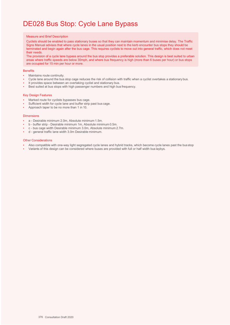
Design Guidance: Active Travel (Wales) Act 2013
330330 version 1 -
DDececemembberer 20201414
DE028 Bus Stop: Cycle Lane Bypass
Benefits ▪ Maintains route continuity. ▪ Cycle lane around the bus stop cage reduces the risk of collision with traffic when a cyclist overtakes a stationary bus. ▪ It provides space between an overtaking cyclist and stationary bus. ▪ Best suited at bus stops with high passenger numbers and high bus frequency.
Key Design Features ▪ Marked route for cyclists bypasses bus cage. ▪ Sufficient width for cycle lane and buffer strip past bus cage. ▪ Approach taper to be no more than 1 in 10.
Dimensions ▪ a - Desirable minimum 2.0m, Absolute minimum 1.5m. ▪ b - buffer strip - Desirable minimum 1m, Absolute minimum 0.5m. ▪ c - bus cage width Desirable minimum 3.0m, Absolute minimum 2.7m. ▪ d - general traffic lane width 3.0m Desirable minimum.
Other Considerations ▪ Also compatible with one-way light segregated cycle lanes and hybrid tracks, which become cycle lanes past the bus stop ▪ Variants of this design can be considered where buses are provided with full or half width bus laybys.
Measure and Brief Description Cyclists should be enabled to pass stationary buses so that they can maintain momentum and minimise delay. The Traffic Signs Manual advises that where cycle lanes in the usual position next to the kerb encounter bus stops they should be terminated and begin again after the bus cage. This requires cyclists to move out into general traffic, which does not meet their needs. The provision of a cycle lane bypass around the bus stop provides a preferable solution. This design is best suited to urban areas where traffic speeds are below 30mph, and where bus frequency is high (more than 6 buses per hour) or bus stops are occupied for 15 min per hour or more.
376 Consultation Draft 2020
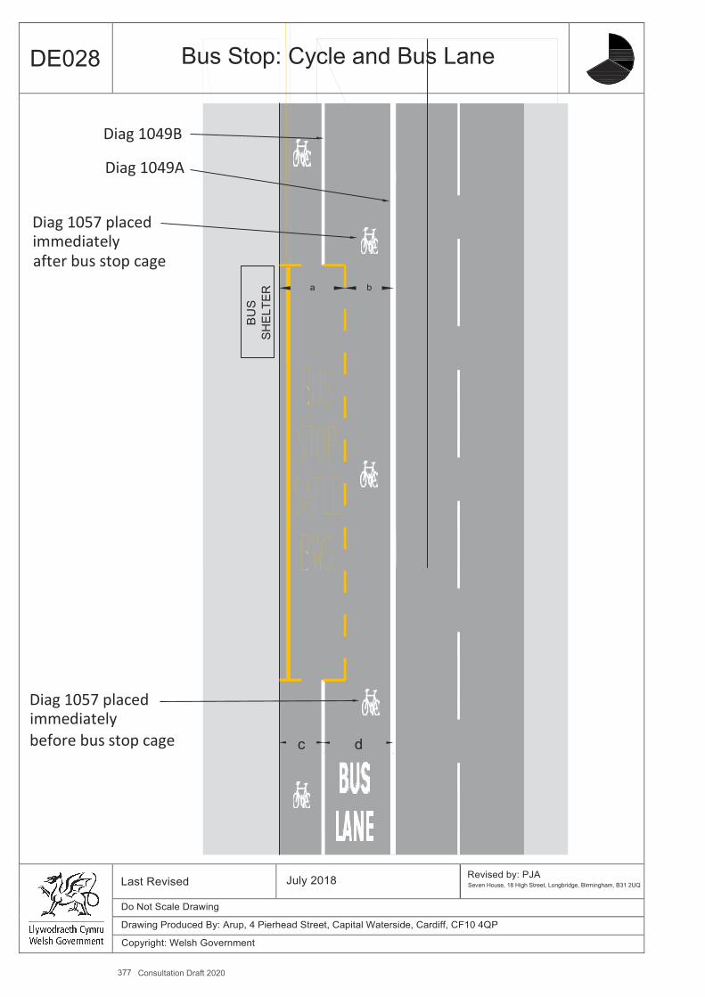
377 Consultation Draft 2020
A4
BU
S
SHEL
TER
DE028 Bus Stop: Cycle and Bus Lane
Diag 1049B
Diag 1049A
Diag 1057 placed immediately after bus stop cage
a b
Diag 1057 placed immediately before bus stop cage c d
Last Revised July 2018 Revised by: PJA Seven House, 18 High Street, Longbridge, Birmingham, B31 2UQ
Do Not Scale Drawing
Drawing Produced By: Arup, 4 Pierhead Street, Capital Waterside, Cardiff, CF10 4QP
Copyright: Welsh Government

Design Guidance: Active Travel (Wales) Act 2013
333322 version 1 - DDececemembberer 20201414
DE029 Bus Stop: Island Bus Stop
Benefits ▪ Maintains route continuity for cyclists. ▪ Eliminates the risk of conflict with buses. ▪ More comfortable and attractive, especially for less confident cyclists.
Key Design Features ▪ Sufficient widths should be provided for pedestrians walking past the stop and on the island to accommodate passengers
waiting for and alighting from buses. ▪ Preferred design includes a humped zebra crossing at footway level, which slows cyclists down providing more reaction
time for pedestrians and increasing convenience for disabled bus users. ▪ Dropped kerbs should be installed if a humped crossing is not used. ▪ Sinusoidal humps preferred on ramps. ▪ Minimum bypass entry / exit taper 1:10 ▪ Tactile paving to be provided at crossing point(s) of cycle track.
Dimensions ▪ a - Desirable minimum 2.0m, Absolute minimum 1.5m. ▪ b – Island width Desirable minimum 2.0m, Absolute minimum 1m.
Other Considerations ▪ This design can be used in conjunction with cycle lanes, cycle lanes with light segregation, hybrid cycle tracks and
segregated off-carriageway tracks. ▪ Pedestrian crossing point(s) should be provided with dropped/flush kerbs if not placed on a flat top hump. ▪ Bypasses should be kept clean and free from debris. ▪ Adequate drainage should be provided using cycle friendly gullies to prevent ponding and icing.
Measure and Brief Description Cyclists should be enabled to pass stationary buses without the risk of moving into a traffic lane. The Traffic Signs Manual advises that where cycle lanes in the usual position next to the kerb encounter bus stops they should be terminated and begin again after the bus cage. This requires cyclists to move out into general traffic, which does not meet their needs.
The safest and most comfortable way to enable cyclists to pass stationary buses is to provide a cycle track past the bus stop on the footway side. Passengers will board and alight from buses from the kerbed island between the cycle track and the carriageway. The suitability of this is dependent on the available space, bus frequency and passenger volume and the number of pedestrians using the footway.
378 Consultation Draft 2020
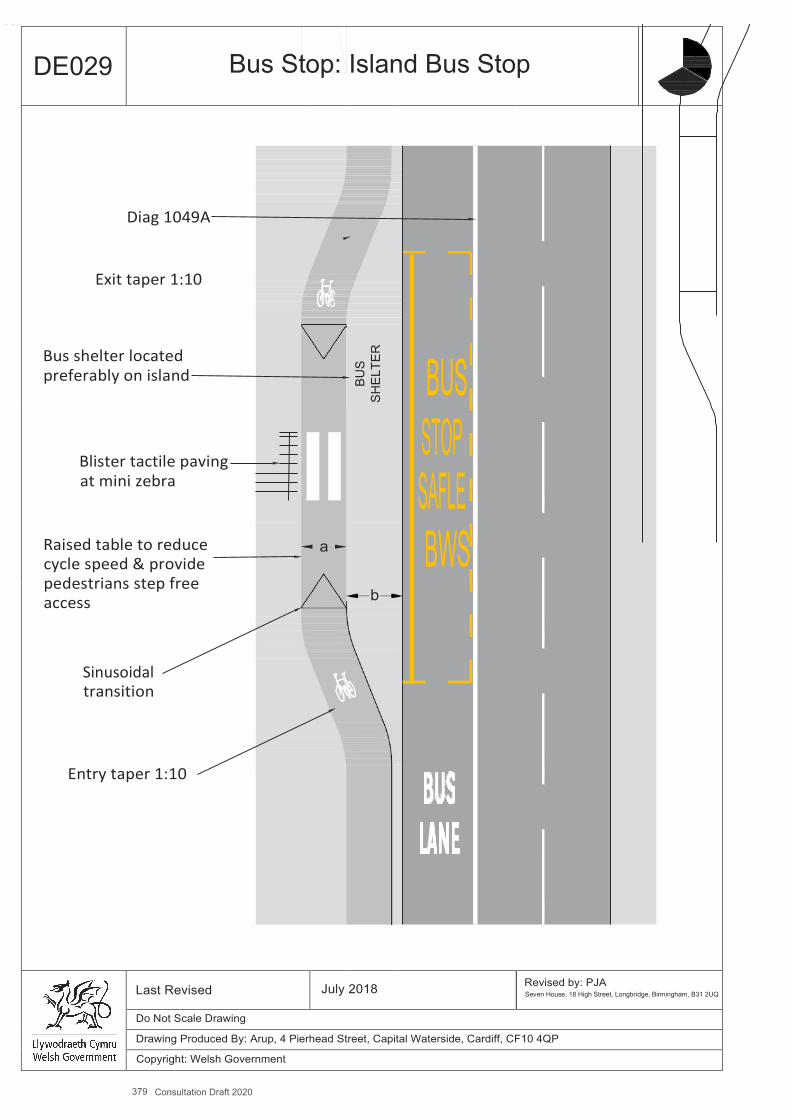
379 Consultation Draft 2020
A4
BUS
SHEL
TER
DE029 Bus Stop: Island Bus Stop
Diag 1049A
Exit taper 1:10
Bus shelter located preferably on island
Blister tactile paving at mini zebra
Raised table to reduce cycle speed & provide pedestrians step free access
Sinusoidal transition
Entry taper 1:10
BUS STOP SAFLE
a BWS b
Last Revised July 2018 Revised by: PJA Seven House, 18 High Street, Longbridge, Birmingham, B31 2UQ
Do Not Scale Drawing
Drawing Produced By: Arup, 4 Pierhead Street, Capital Waterside, Cardiff, CF10 4QP
Copyright: Welsh Government

Design Guidance: Active Travel (Wales) Act 2013
334334 version 1 - DDececemembberer 20201414
DE030 Bus Stop: Bus Boarder
Benefits ▪ Maintains route continuity. ▪ Eliminates the risk of conflict with buses. ▪ More comfortable and attractive, especially for less confident cyclists. ▪ Bus boarder provides step free access for bus users.
Key Design Features ▪ Ramp up to footway level to help reduce cycle speeds. ▪ Where the difference between levels is small a short ramp may be appropriate. ▪ Bus shelters and flags should be placed at the back of the bus boarder. ▪ Sufficient space should be provided at the back of bus stop to minimise pedestrians needing to stand in the line of cycle
track. ▪ Good intervisibility is required between pedestrians (those waiting for a bus as well as those passing) and cyclists, to
minimise potential for conflict. ▪ The bus stop should be apparent to cyclists, who will need to be able to adjust their behaviour and speed to reflect the
additional risk of conflict.
Dimensions ▪ a - Bus boarder width Desirable minimum 2.0m, Absolute minimum1.5m. ▪ b – Retained footway width Desirable minimum 3.0m, Absolute minimum 2.0m.
Other Considerations ▪ Potential for conflict with pedestrians using the bus stop. ▪ This design can be considered in conjunction with cycle lanes, light segregation or one-way hybrid cycle tracks.
Measure and Brief Description Cyclists should be enabled to pass stationary buses so that they can maintain momentum and minimise delay. The Traffic Signs Manual advises that where cycle lanes in the usual position next to the kerb encounter bus stops they should be terminated and begin again after the bus cage. This requires cyclists to move out into general traffic, which does not meet their needs.
Provision of a bus boarder in line with the cycle lane/track will bring cyclists up to footway level onto a shared use area enabling them to continue across the bus boarder when it is clear or to cycle past pedestrians waiting at the bus stop. Careful consideration needs to given in how to minimise conflict between cyclists and pedestrians - this option is best suited to bus stops and footways with low passenger and pedestrian volumes.
380 Consultation Draft 2020
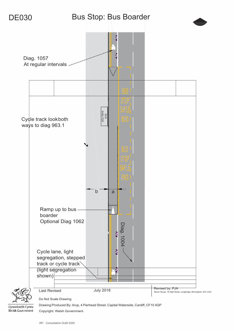
381 Consultation Draft 2020
A4
DE030 Bus Stop: Bus Boarder
Diag. 1057 At regular intervals
Cycle track look both ways to diag 963.1
b
Ramp up to bus boarder Optional Diag 1062
Cycle lane, light segregation, stepped track or cycle track (light segregation shown)
Last Revised July 2018 Revised by: PJA Seven House, 18 High Street, Longbridge, Birmingham, B31 2UQ
Do Not Scale Drawing
Drawing Produced By: Arup, 4 Pierhead Street, Capital Waterside, Cardiff, CF10 4QP
Copyright: Welsh Government
a
Diag. 1004
BU
S
SH
ELTE
R

Design Guidance: Active Travel (Wales) Act 2013
336336 version 1 - DDececemembberer 20201414
DE031 Bus Stop: Shared Use
Benefits ▪ Maintains route continuity. ▪ Eliminates the risk of conflict with buses. ▪ Comfortable and attractive, especially for less confident cyclists.
Key Design Features ▪ Cycle track segregation ends each side of bus stop becoming a shared path. ▪ Shared path past bus stop to be kept clear of street furniture. ▪ There should be a clear space for passengers to wait where will not come into conflict with cyclists. ▪ Good intervisibility between pedestrians (those waiting for a bus as well as those passing) and cyclists, to minimise potential
for conflict. ▪ The bus stop should be apparent to cyclists, who will need to be able to adjust their behaviour and speed to reflect the
additional risk of conflict.
Dimensions ▪ a – Retained shared use path width Desirable minimum 3.0m, Absolute minimum 2.0m. ▪ Cycle track should finish at least 15m before waiting area (in direction of general traffic) and continue 5m past.
Other Considerations ▪ Potential for conflict with pedestrians using the bus stop or footway.
Measure and Brief Description Bus stops can pose a difficulty on two-way cycle tracks adjacent to the carriageway, as street furniture and waiting pedestrians associated with the bus stop can cause an obstruction and it will be difficult to maintain the width required for a fully separated track. Consequently an option is to share the entire width of the path past the bus stop.
382 Consultation Draft 2020
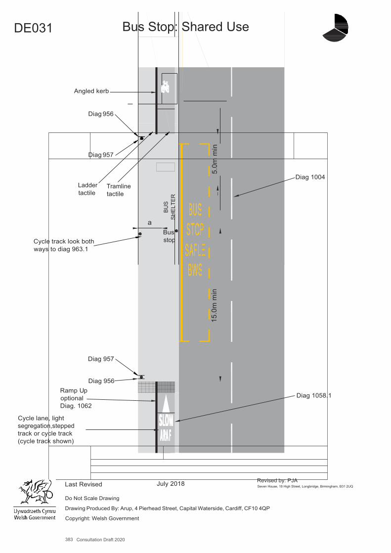
383 Consultation Draft 2020
A4
DE031 Bus Stop: Shared Use
Angled kerb
Diag 956
Diag 957
Ladder tactile
Tramline tactile
Diag 1004
Cycle track look both ways to diag 963.1
a Bus stop
Diag 957
Ramp Up optional
Diag 956
Diag 1058.1 Diag. 1062
Cycle lane, light segregation,stepped track or cycle track (cycle track shown)
Last Revised July 2018 Revised by: PJA Seven House, 18 High Street, Longbridge, Birmingham, B31 2UQ
Do Not Scale Drawing
Drawing Produced By: Arup, 4 Pierhead Street, Capital Waterside, Cardiff, CF10 4QP
Copyright: Welsh Government
BUS
SHEL
TER
15.0
m m
in
5.
0m m
in
Design Guidance: Active Travel (Wales) Act 2013
338338 version 1 -DDececemembberer 20201414
DE032 Cycle Track Away From Road, Separated From Pedestrians
Benefits▪ Provides routes which are free from conflict with motor traffic.▪ Segregated paths allow each group to move at their own desired pace and improve comfort and subjectivesafety.
Key Design Features▪ Footpaths and cycle tracks should be continuous.▪ Flush kerbs with tactile paving at road crossings.▪ Cycle tracks should not deflect more than 45º from cyclists’ desire line and changes in height should beavoided.▪ Machine-laid black bituminous surfacing should be used as it will make cycle journeys safer, more comfortable and helps
distinguish cycle tracks from adjacent footways surfaced by paviours or slabs.
Dimensions▪ a - The width for pedestrians should reflect the level and type of use forecast with an Absolute minimum of 2m, increasing to
a Desirable minimum of 3.5m where there is frequent use by groups. 1.5m may be acceptable over short lengths, however– see DE001
▪ b - Cycle track width should be sufficient to accommodate the forecast level of use with a minimum of:Absolute minimum 2.5m, where the peak hour flow is less than 50/hr;Desirable minimum 3.0m, where it is 50-250/hr, 4m for cycle flows over 250/hr.
▪ Cycle tracks should include additional width where they are bounded by vertical features. Additional width requiredisKerb up to 150mm high: add 200mm.Vertical feature 150-600mm high: add 250mm.Vertical feature above 600mm high: add 500mm.
▪ Verges separating pedestrian and cycle routes should be a minimum of 1.0m wide.
Other Considerations▪ Generally cycle tracks will be two-way.▪ Centre lines should be marked on two-way cycle tracks.▪ Lamp columns and other street furniture should be set back at least 0.5m from the edge of the cycle track.▪ Path geometry, particularly radii, forward visibility and gradient, should reflect the user need criteria set out in Chapter13.▪ Paths used for utility journeys (all Active Travel Routes) should normally be lit.▪ Access control features should not be installed unless absolutely necessary.
Measure and Brief DescriptionRoutes away from the road can provide a very good quality link for both pedestrians and cyclists. A separate parallel path for pedestrians is desirable, and sufficient width should be provided for each user group so that they do not encroach on the other users’ path.
Physical segregation is generally preferred provided widths are adequate and this can be through a level difference or verge. Barriers are not desirable since they limit the effective width of the paths and are a particular hazard to cyclists. Segregation using only simple white lines (Diag 1049) (which are not detectable by blind users) or a raised white line delineator (Diag 1049.1), is an option but it is rarely respected by pedestrians (who have the legal right to use the cycle track) in practice, unless cycle flows are high or there is generous width, and should be avoided.
384 Consultation Draft 2020
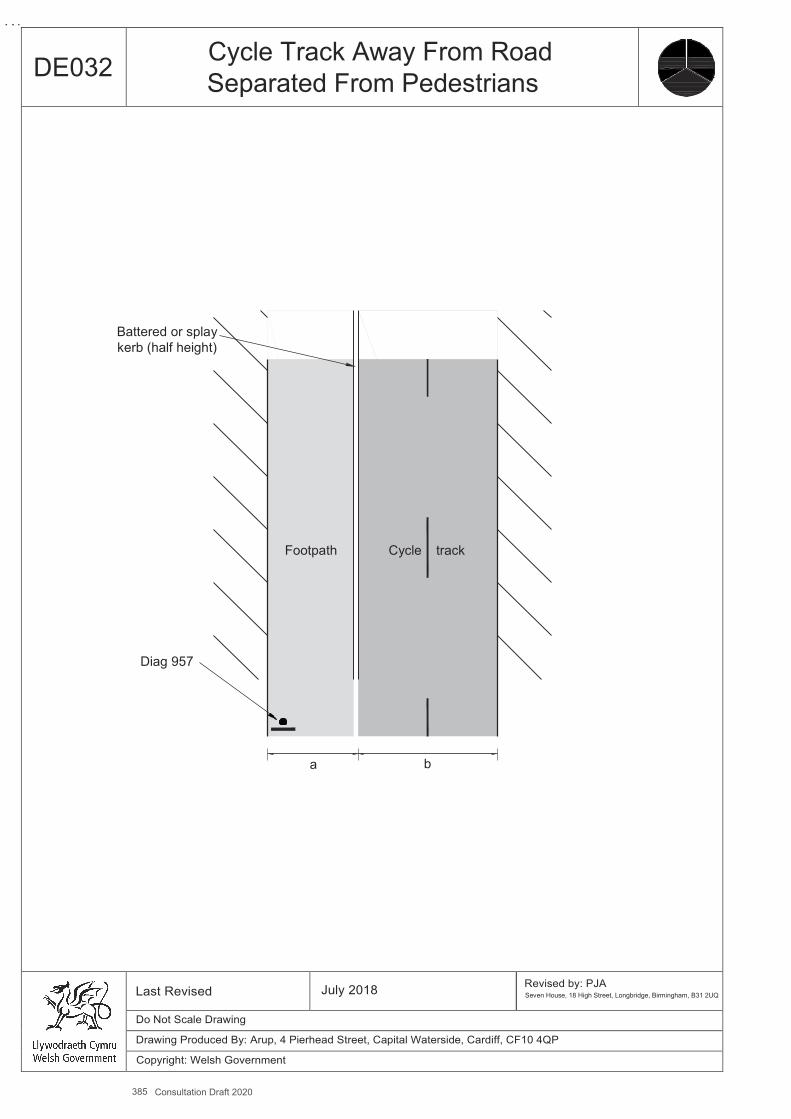
385 Consultation Draft 2020
A4
DE032 Cycle Track Away From Road Separated From Pedestrians
Battered or splay kerb (half height)
Footpath Cycle track
Diag 957
a b
Last Revised July 2018 Revised by: PJA Seven House, 18 High Street, Longbridge, Birmingham, B31 2UQ
Do Not Scale Drawing
Drawing Produced By: Arup, 4 Pierhead Street, Capital Waterside, Cardiff, CF10 4QP
Copyright: Welsh Government
Design Guidance: Active Travel (Wales) Act 2013
340340 version 1 - DDececemembberer 20201414
DE033 Cycle Track Away From Road, Shared With Pedestrians
Key Design Features ▪ Footpaths and cycle tracks should be continuous. ▪ Flush kerbs with tactile paving at road crossings. ▪ Cycle tracks should not deflect more than 45º from cyclists’ desire line and constant changes in height should be avoided ▪ Machine-laid bituminous surfacing should be used as it will make cycle journeys safer and more comfortable.
Dimensions ▪ a - width should reflect the level and type of use forecast with a minimum of 3m width on primary cycle routes, or 2.5m on
less busy secondary routes. On particularly heavily trafficked routes it should be increased to 4m. ▪ Shared use cycle tracks should include additional width where they are bounded by vertical features. Only where there is
open space on both sides is it is practical to use the whole track width to cycle. Additional width required is: Kerb up to 150mm high: add 200mm; Vertical feature 150-600mm high: add 250mm; Vertical feature above 600mm high: add 500mm.
Other Considerations ▪ Generally cycle tracks will be two-way. ▪ Centre lines should be marked on two-way cycle tracks. ▪ Lamp columns and other street furniture should be set back at least 0.5m from the edge of the cycle track. ▪ Path geometry, particularly radii, forward visibility and gradient, should reflect the user need criteria set out in Chapter 4. ▪ Paths used for utility journeys (all Active Travel Routes) should normally be lit. ▪ Access control features should not be installed unless absolutely necessary. ▪ The British Horse Society recommends a desirable minimum width of 5.0m for new bridleways, which would be shared
with pedestrians and cyclists.
Measure and Brief Description Routes away from the road can provide a very good quality link for both pedestrians and cyclists. Where a cycle track is to be provided which will be shared with pedestrians, sufficient width must be provided for the two user groups to interact safely and in comfort. It is essential that developing the design of an unsegregated shared use track includes early consultation with relevant interested parties such as those representing people with disabilities, walkers and cyclists.
386 Consultation Draft 2020
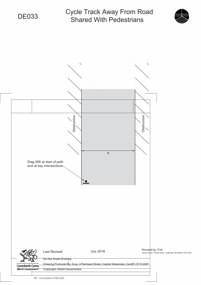
387 Consultation Draft 2020
A4
DE033
Cycle Track Away From Road Shared With Pedestrians
Diag 956 at start of path and at key intersections
Last Revised July 2018 Revised by: PJA Seven House, 18 High Street, Longbridge, Birmingham, B31 2UQ
Do Not Scale Drawing
Drawing Produced By: Arup, 4 Pierhead Street, Capital Waterside, Cardiff, CF10 4QP
Copyright: Welsh Government
a
Obs
truct
ion
Obs
truct
ion
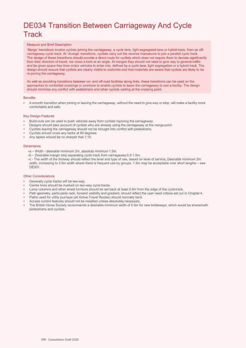
Design Guidance: Active Travel (Wales) Act 2013
342342 version 1 - DDececemembberer 20201414
DE034 Transition Between Carriageway And Cycle Track
Benefits ▪ A smooth transition when joining or leaving the carriageway, without the need to give way or stop, will make a facility more
comfortable and safe.
Key Design Features ▪ Build-outs can be used to push vehicles away from cyclists rejoining the carriageway.▪ Designs should take account of cyclists who are already using the carriageway at the merge point.▪ Cyclists leaving the carriageway should not be brought into conflict with pedestrians.▪ Cyclists should cross any kerbs at 90 degrees.▪ Any tapers should be no sharper that 1:10.
Dimensions ▪ a – Width - desirable minimum 2m, absolute minimum 1.5m.▪ b – Desirable margin strip separating cycle track from carriageway 0.5-1.0m.▪ c - The width of the footway should reflect the level and type of use, based on level of service, Desirable minimum 2mwidth, increasing to 3.5m width where there is frequent use by groups. 1.5m may be acceptable over short lengths – seeDE001.
Other Considerations ▪ Generally cycle tracks will be two-way.▪ Centre lines should be marked on two-way cycle tracks.▪ Lamp columns and other street furniture should be set back at least 0.5m from the edge of the cycle track.▪ Path geometry, particularly radii, forward visibility and gradient, should reflect the user need criteria set out in Chapter 4.▪ Paths used for utility journeys (all Active Travel Routes) should normally be lit.▪ Access control features should not be installed unless absolutely necessary.▪ The British Horse Society recommends a desirable minimum width of 5.0m for new bridleways, which would be shared with
pedestrians and cyclists.
Measure and Brief Description ‘Merge’ transitions involve cyclists joining the carriageway, a cycle lane, light segregated lane or hybrid track, from an off- carriageway cycle track. At ‘diverge’ transitions, cyclists carry out the reverse manoeuvre to join a parallel cycle track. The design of these transitions should provide a direct route for cyclists which does not require them to deviate significantly from their direction of travel, nor cross a kerb at an angle. At merges they should not need to give way to general traffic and be given space free from motor vehicles to enter into, defined by a cycle lane, light segregation or a hybrid track. The design should ensure that cyclists are clearly visible to motorists and that motorists are aware that cyclists are likely to be re-joining the carriageway.
As well as providing transitions between on- and off-road facilities along links, these transitions can be used on the approaches to controlled crossings or junctions to enable cyclists to leave the carriageway to use a facility. The design should minimise any conflict with pedestrians and other cyclists waiting at the crossing point.
388 Consultation Draft 2020
389 Consultation Draft 2020
A4
DE034 Transition Between Cycle Lane
and Cycle Track
Diag 1057
Diag 1049B (or 1004)
b
c a
Change in level
Ladder Tactile
Diag 957 or Diag 956
Lane marking Diag 1004
Tramline Tactile
Cycle track (length varies)
Ladder Tactile
Margin strip
Flush kerb or Diag 1049B white line delineator
Diag 957 or Diag956
Ramp with optional diag 1062
Cycle lane or, light segregation Diag 1049B (or 1004)
Last Revised July 2018 Revised by: PJA Seven House, 18 High Street, Longbridge, Birmingham, B31 2UQ
Do Not Scale Drawing
Drawing Produced By: Arup, 4 Pierhead Street, Capital Waterside, Cardiff, CF10 4QP
Copyright: Welsh Government
Foot
way
Fo
otw
ay
Kerb
line
Kerb
line
Car
riage
way
C
arria
gew
ay
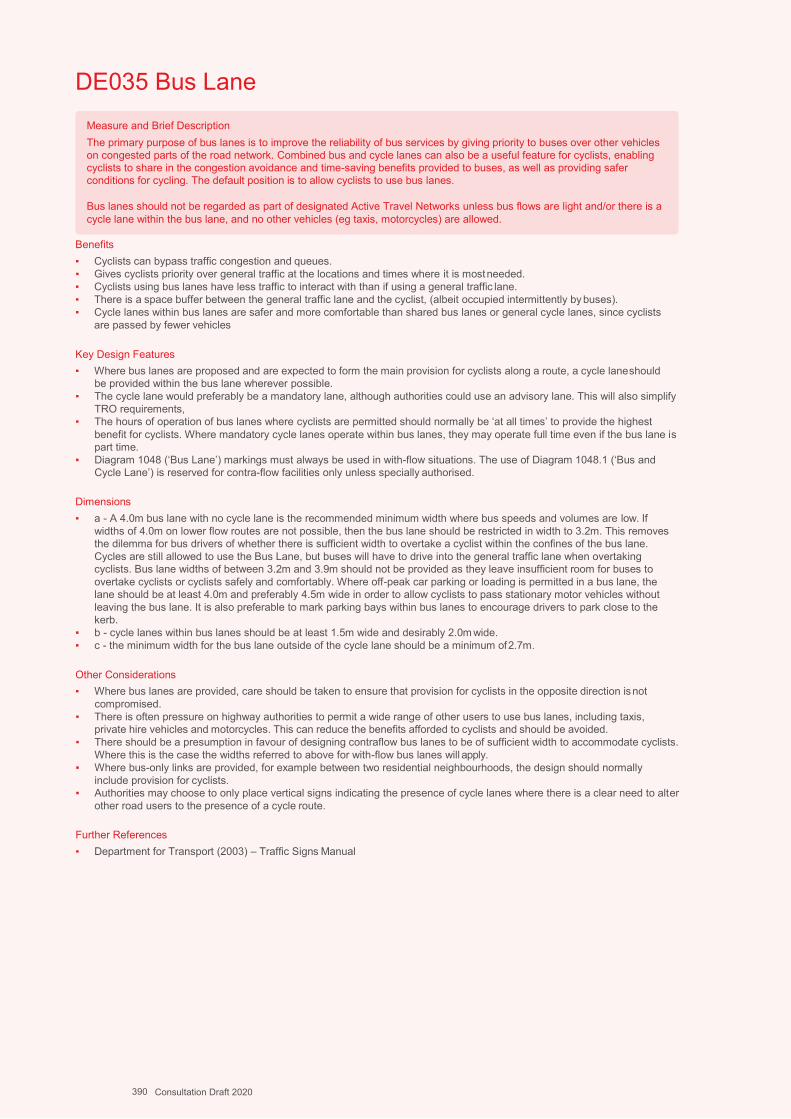
Design Guidance: Active Travel (Wales) Act 2013
344344 version 1 -
DDececemembberer 20201414
DE035 Bus Lane
Benefits ▪ Cyclists can bypass traffic congestion and queues. ▪ Gives cyclists priority over general traffic at the locations and times where it is most needed. ▪ Cyclists using bus lanes have less traffic to interact with than if using a general traffic lane. ▪ There is a space buffer between the general traffic lane and the cyclist, (albeit occupied intermittently by buses). ▪ Cycle lanes within bus lanes are safer and more comfortable than shared bus lanes or general cycle lanes, since cyclists
are passed by fewer vehicles
Key Design Features ▪ Where bus lanes are proposed and are expected to form the main provision for cyclists along a route, a cycle lane should
be provided within the bus lane wherever possible. ▪ The cycle lane would preferably be a mandatory lane, although authorities could use an advisory lane. This will also simplify
TRO requirements, ▪ The hours of operation of bus lanes where cyclists are permitted should normally be ‘at all times’ to provide the highest
benefit for cyclists. Where mandatory cycle lanes operate within bus lanes, they may operate full time even if the bus lane is part time.
▪ Diagram 1048 (‘Bus Lane’) markings must always be used in with-flow situations. The use of Diagram 1048.1 (‘Bus and Cycle Lane’) is reserved for contra-flow facilities only unless specially authorised.
Dimensions ▪ a - A 4.0m bus lane with no cycle lane is the recommended minimum width where bus speeds and volumes are low. If
widths of 4.0m on lower flow routes are not possible, then the bus lane should be restricted in width to 3.2m. This removes the dilemma for bus drivers of whether there is sufficient width to overtake a cyclist within the confines of the bus lane. Cycles are still allowed to use the Bus Lane, but buses will have to drive into the general traffic lane when overtaking cyclists. Bus lane widths of between 3.2m and 3.9m should not be provided as they leave insufficient room for buses to overtake cyclists or cyclists safely and comfortably. Where off-peak car parking or loading is permitted in a bus lane, the lane should be at least 4.0m and preferably 4.5m wide in order to allow cyclists to pass stationary motor vehicles without leaving the bus lane. It is also preferable to mark parking bays within bus lanes to encourage drivers to park close to the kerb.
▪ b - cycle lanes within bus lanes should be at least 1.5m wide and desirably 2.0m wide. ▪ c - the minimum width for the bus lane outside of the cycle lane should be a minimum of 2.7m.
Other Considerations ▪ Where bus lanes are provided, care should be taken to ensure that provision for cyclists in the opposite direction is not
compromised. ▪ There is often pressure on highway authorities to permit a wide range of other users to use bus lanes, including taxis,
private hire vehicles and motorcycles. This can reduce the benefits afforded to cyclists and should be avoided. ▪ There should be a presumption in favour of designing contraflow bus lanes to be of sufficient width to accommodate cyclists.
Where this is the case the widths referred to above for with-flow bus lanes will apply. ▪ Where bus-only links are provided, for example between two residential neighbourhoods, the design should normally
include provision for cyclists. ▪ Authorities may choose to only place vertical signs indicating the presence of cycle lanes where there is a clear need to alter
other road users to the presence of a cycle route.
Further References ▪ Department for Transport (2003) – Traffic Signs Manual
Measure and Brief Description The primary purpose of bus lanes is to improve the reliability of bus services by giving priority to buses over other vehicles on congested parts of the road network. Combined bus and cycle lanes can also be a useful feature for cyclists, enabling cyclists to share in the congestion avoidance and time-saving benefits provided to buses, as well as providing safer conditions for cycling. The default position is to allow cyclists to use bus lanes.
Bus lanes should not be regarded as part of designated Active Travel Networks unless bus flows are light and/or there is a cycle lane within the bus lane, and no other vehicles (eg taxis, motorcycles) are allowed.
390 Consultation Draft 2020
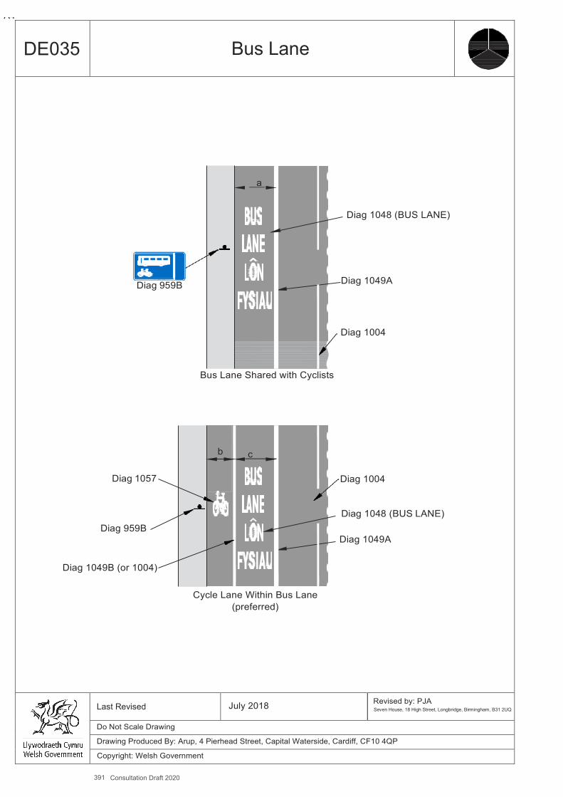
391 Consultation Draft 2020
A4
DE035 Bus Lane
a
Diag 1048 (BUS LANE)
Diag 959B Diag 1049A
Diag 1004
Bus Lane Shared with Cyclists
b c
Diag 1057 Diag 1004
Diag 1048 (BUS LANE) Diag 959B
Diag 1049A
Diag 1049B (or 1004)
Cycle Lane Within Bus Lane (preferred)
Last Revised July 2018 Revised by: PJA
Seven House, 18 High Street, Longbridge, Birmingham, B31 2UQ
Do Not Scale Drawing
Drawing Produced By: Arup, 4 Pierhead Street, Capital Waterside, Cardiff, CF10 4QP
Copyright: Welsh Government
Design Guidance: Active Travel (Wales) Act 2013
346346 version 1 -
DDececemembberer 20201414
DE036 Simple Uncontrolled Crossings (Walking, Shared Use or Cycle Only)
Benefits ▪ Alerts drivers to the presence of crossing pedestrians and cyclists. ▪ Indicates to pedestrians a suitable crossing place. ▪ Relatively cheap to install.
Key Design Features ▪ Tactile paving to be provided at dropped kerbs. ▪ A coloured surface may be useful to highlight the presence of the crossing to motor traffic. ▪ If the road has a speed limit of 30 mph or less, the crossing may be placed on a flat topped road hump. If so, it needs tobe
made clear to cyclists that they must give way when crossing. ▪ Road humps must comply with the Highways Act 1980, Sections 90A to 90F. ▪ Where it is not clear to cyclists approaching the crossing that they are about to meet a road, it may be worthwhile adding
markings (and possibly signs) indicating that they should give way. ▪ On single carriageway roads with two lanes where the national speed limit of 60mph applies or on other rural roads where a
lower speed limit is in place, consideration should be given to additional measures such as light coloured antiskid surfacing for 50m either side of the crossing, rumble strips on the approaches, localised visual narrowing in vicinity of crossing and Diagram 950 warning signs on the approaches.
Dimensions ▪ Width of crossing (a) to be at least as wide as the path either side. On pedestrian only routes this should be 2m min, on
shared use paths, 3m min
Other Considerations ▪ Any coloured surface needs to maintain a good condition to remain effective. ▪ The effect of parked vehicles in the vicinity of an uncontrolled crossing should be considered and if necessary parking
restrictions imposed to maintain adequate visibility. ▪ Vehicle crossovers are not suitable as pedestrian crossing points and care should be taken over the siting of crossings
relative to crossovers so as not to cause confusion to users. ▪ Build outs can reduce the crossing distance, and in some situations will aid visibility, but can impede on-road cyclists.
Designers should understand the impact that creating a better crossing point can have on a cyclist already on the road. ▪ Physical changes to the kerb lines can be costly but reducing the carriageway width is an effective solution. ▪ In rural locations detectors on the approach paths can be used to trigger vehicle activated signs to alert motor traffic of the
presence of an infrequently used crossing only when there are cyclists or pedestrians present.
Measure and Brief Description This is the simplest form of pedestrian or cycle crossing where a footway, footpath or cycle track meets the road at a dropped kerb.
392 Consultation Draft 2020
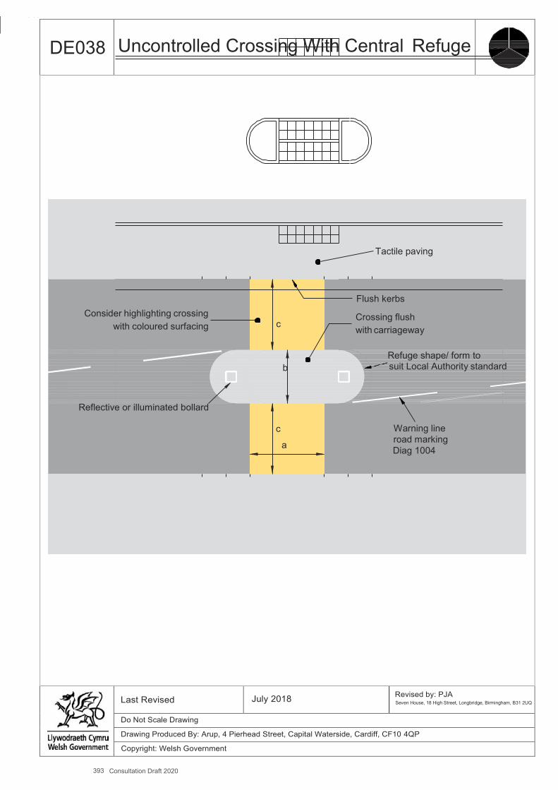
393 Consultation Draft 2020
A4
DE038 Uncontrolled Crossing With Central Refuge
Tactile paving
Flush kerbs Consider highlighting crossing Crossing flush
with coloured surfacing c with carriageway
Refuge shape/ form to
b suit Local Authority standard
Reflective or illuminated bollard
c Warning line
a road marking Diag 1004
Last Revised July 2018 Revised by: PJA Seven House, 18 High Street, Longbridge, Birmingham, B31 2UQ
Do Not Scale Drawing
Drawing Produced By: Arup, 4 Pierhead Street, Capital Waterside, Cardiff, CF10 4QP
Copyright: Welsh Government

Design Guidance: Active Travel (Wales) Act 2013
352352 version 1 - DDececemembberer 20201414
DE039 Side Road Entry Treatment
Benefits ▪ Side road entry treatments make it easier and more convenient for pedestrians to cross the side road ▪ They also provide safety benefits to cyclists, helping to prevent collisions with motor vehicles turning into and out of the side
road
Key Design Features ▪ Raising the carriageway to footway level across the mouth of the side road. ▪ Narrowing the side road to shorten the crossing distance and reduce traffic speeds. ▪ Tightening the corner radii of side road junctions which will slow down turning vehicles and enable the crossing point to be
closer to the desire line. ▪ The top of the raised table should be constructed in material which contrasts with the carriageway to indicate to drivers that
they should treat it differently. It may be paved in a similar material to the footway on either side. ▪ Tactile paving to be provided at the pedestrian crossing points.
Dimensions ▪ a - Corner radii – Desirable maximum 3.0m, Absolute maximum 6.0m.
Other Considerations ▪ Raised tables are a form of traffic calming and as such cannot be used on roads with a speed limit greater than 40 mph. ▪ Consideration should be gradient of the ramp so as not to create a hazard for motorcycles and cyclists turning into the side
road. ▪ Corner radii will depend the swept path requirements of vehicles turning into or out of the side road (allowing for vehicles to
cross centrelines unless flows are high). ▪ Tight corner radii will enable pedestrian crossing points to be provided on the desire line. ▪ Bollards may be provided to prevent over-run on corners. ▪ Strengthened corners may be necessary if over-run is to be expected. ▪ Care should be taken to ensure adequate drainage provision to prevent ponding of water at the bottom of the ramps with a
raised table, or in the corners of build outs.
-
Measure and Brief Description Pedestrian crossings will be usually be provided across minor roads at side road junctions, if only in the form of dropped kerbs. Side road entry treatments involve raising and narrowing the mouth of the junction to make it easier and safer for pedestrians to cross the minor arm by reducing the speeds of turning vehicles, shortening the length of the crossing and providing a level route. The side road entry treatment also encourages drivers to give way to pedestrians who have started to cross.
394 Consultation Draft 2020
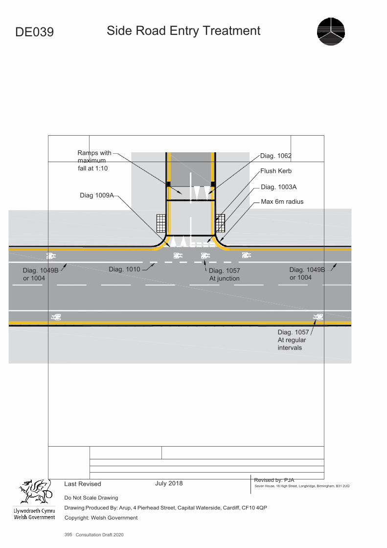
395 Consultation Draft 2020
A4
DE039 Side Road Entry Treatment
Ramps with maximum
Diag. 1062
fall at 1:10 Flush Kerb
Diag 1009A
Diag. 1003A
Max 6m radius
Diag. 1049B or 1004
Diag. 1010
Diag. 1057 At junction
Diag. 1049B or 1004
Diag. 1057 At regular intervals
Last Revised July 2018 Revised by: PJA Seven House, 18 High Street, Longbridge, Birmingham, B31 2UQ
Do Not Scale Drawing
Drawing Produced By: Arup, 4 Pierhead Street, Capital Waterside, Cardiff, CF10 4QP
Copyright: Welsh Government

Design Guidance: Active Travel (Wales) Act 2013
354354 version 1 -
DDececemembberer 20201414
DE040 Blended Side Road Entry Treatment
Benefits ▪ Blended side road entry treatments make it easier and more convenient for pedestrians to cross the side road ▪ They also provide safety benefits to cyclists, helping to prevent collisions with motor vehicles turning into and out of the side
road
Key Design Features ▪ Raising the carriageway to footway level across the mouth of the side road. ▪ Narrowing the side road to shorten the crossing distance and reduce traffic speeds. ▪ Tightening the corner radii of side road junctions which will slow down turning vehicles and enable the crossing point to be
closer to the desire line. ▪ The top of the raised table should be constructed in material which contrasts with the carriageway to indicate to drivers that
they should treat it differently. It may be paved in a similar material to the footway on either side. ▪ Tactile paving is not provided as it suggests that pedestrians should give way to turning vehicles. The design relies on the
fact that vehicles are crossing over a continuous footway.
Dimensions ▪ a - Corner radii – Desirable maximum 3m, Absolute maximum 6m.
Other Considerations ▪ Raised tables are a form of traffic calming and as such cannot be used on roads with a speed limit greater than 40 mph. ▪ Consideration should be gradient of the ramp so as not to create a hazard for motorcycles and cyclists turning into the side
road. ▪ Corner radii will depend the swept path requirements of vehicles turning into or out of the side road (allowing for vehicles to
cross centre lines unless flows are high). ▪ Tight corner radii will enable pedestrian crossing points to be provided on the desire line. ▪ Bollards may be provided to prevent over-run on corners. ▪ Strengthened corners may be necessary if over-run is to be expected. ▪ Care should be taken to ensure adequate drainage provision to prevent ponding of water at the bottom of the ramps with a
raised table, or in the corners of build outs.
-
Measure and Brief Description Pedestrian crossings will be usually be provided at side road junctions, if only in the form of dropped kerbs. Blended side road entry treatments involve continuing the footway across the mouth of the junction without any change to make it easier and safer for pedestrians to cross by reducing the speeds of turning vehicles, shortening the length of the crossing and providing a level route. The continuous footway strongly indicates to drivers that they should to give way to pedestrians using the footway.
396 Consultation Draft 2020
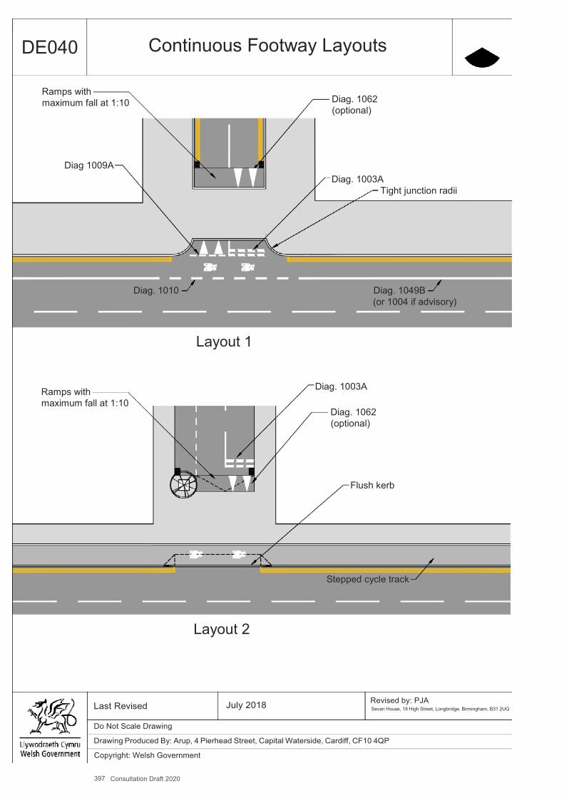
397 Consultation Draft 2020
A4
DE040 Continuous Footway Layouts
Ramps with maximum fall at 1:10
Diag. 1062 (optional)
Diag 1009A
Diag. 1003A Tight junction radii
Diag. 1010 Diag. 1049B (or 1004 if advisory)
Layout 1
Ramps with maximum fall at 1:10
Diag. 1003A
Diag. 1062 (optional)
Flush kerb
Stepped cycle track
Layout 2
Last Revised July 2018 Revised by: PJA Seven House, 18 High Street, Longbridge, Birmingham, B31 2UQ
Do Not Scale Drawing
Drawing Produced By: Arup, 4 Pierhead Street, Capital Waterside, Cardiff, CF10 4QP
Copyright: Welsh Government

Design Guidance: Active Travel (Wales) Act 2013
356356 version 1 - DDececemembberer 20201414
DE041 Central Median Strip
Benefits ▪ Central median strips enable pedestrians to cross carriageways in two stages away from formal crossing points. ▪ This is particularly useful where crossing movements are distributed along a significant length, for example along a
shopping street. ▪ These strips can also enhance the character of a highway and help to lower vehicle speeds. They also provide safety
benefits to cyclists, helping to prevent collisions with motor vehicles turning into and out of the side road
Key Design Features ▪ The width of the central median needs to be sufficient for a pedestrian to wait safely in the median for a gap in the traffic. ▪ The median may be constructed to enable vehicular overrun, or kerbed to prevent vehicular overrun. ▪ Kerbed medians will give the most confidence to pedestrians crossing. Central medians can be designed to be overrun so
that the carriageways can be kept narrow but still allow for vehicles to pass stationary buses etc. ▪ Strips that are designed to be overrun can be flush or domed and/or constructed in rough surfacing so that vehicles travel
slowly when travelling across the median. ▪ Designated crossing points may still be provided at intervals, with flush kerbs on the median and at the kerbs on the
opposite side of the carriageways. Tactile paving should be provided at these flush kerbs. Raising the carriageway to footway level across the mouth of the side road.
Dimensions ▪ a - Lane width either side to be below 3.2m or above 3.9m, avoiding the critical lane width range for cyclists. ▪ b – Width of median strip should be a desirable minimum of 2.0m to accommodate a wheelchair and the person pushing
and an absolute minimum of 1.2m. ▪ Minimum kerb height of 60mm is recommended, with an absolute minimum of 50mm.
Other Considerations ▪ Unless kerbed, the form of construction of the median strip will need to accommodate vehicular overrun. ▪ Subject to vehicle tracking requirements, trees and planting can be placed in the central median.
-
Measure and Brief Description A central median strip is a long paved area of different coloured or textured surfacing in the centre of a carriageway which provides space for pedestrians to wait in while crossing a road in two stages at any point along its length.
398 Consultation Draft 2020
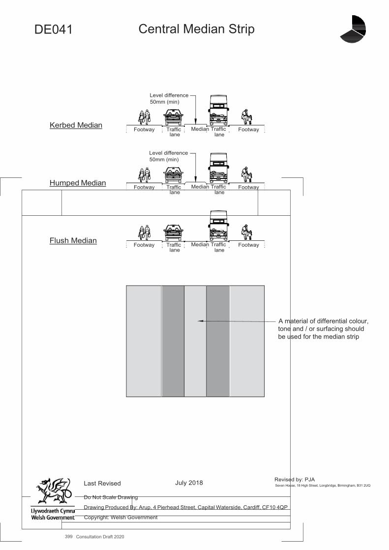
399 Consultation Draft 2020
A4
DE041
Central Median Strip
Level difference 50mm (min)
Kerbed Median
Footway Traffic lane
Median Traffic lane
Footway
Level difference 50mm (min)
Humped Median
Footway Traffic lane
Median Traffic lane
Footway
Flush Median Footway Traffic
lane
Median Traffic
lane
Footway
A material of differential colour, tone and / or surfacing should be used for the median strip
Last Revised
July 2018
Revised by: PJA Seven House, 18 High Street, Longbridge, Birmingham, B31 2UQ
Do Not Scale Drawing
Drawing Produced By: Arup, 4 Pierhead Street, Capital Waterside, Cardiff, CF10 4QP
Copyright: Welsh Government

Design Guidance: Active Travel (Wales) Act 2013
358358 version 1 - DDececemembberer 20201414
DE042 Zebra Crossing
Benefits ▪ Zebra crossings provide relatively low-cost pedestrian priority crossing facilities which give an immediate response to
pedestrians’ need to cross. ▪ They can be placed closer to junctions than signalised crossings, reducing the need to deviate from desire lines. ▪ Unless pedestrian flows are very high they result in lower delays to vehicles. Central median strips enable pedestrians to
cross carriageways in two stages away from formal crossing points.
Key Design Features ▪ There should be adequate visibility to a zebra crossing to ensure that approaching motorists can see a pedestrian about to
cross the road. ▪ Zebra crossings may be sited on a flat-topped road hump (raised table) to slow traffic and highlight the presence of the
crossing. ▪ Zebra crossings may either cross a full width carriageway in a single stage or comprise two crossings with a central refuge. ▪ Zebra crossings can be used across minor junctions close to the give way line. ▪ Zebra crossings should be at least five metres from a side road junction, measured from the driver’s position in the adjacent
road. ▪ When provided on the approach or exit from a roundabout Zebra crossings should be located between 5m and 20m from
the give way line. ▪ 8 zig zag markings are normally provided on either side of the crossing, which prevent parking, loading or overtaking. The
maximum number is 18 and the minimum number is 2. ▪ Zig zag markings can be placed up to 2.0m from the kerbline so that space for cycling can be maintained up to the crossing. ▪ Tactile paving to be provided.
Dimensions ▪ a – Crossing width 4m min, 10m max. ▪ b – Distance of give way line to crossing 1.1m min, 3m max.
Other Considerations ▪ A blind person would not start to cross until sure that vehicles have stopped and would therefore seek a pedestrian
controlled signal crossing. Other groups of pedestrians, including people with learning impairments and older people may feel safer and more comfortable using signalised crossings.
▪ Zebra crossings are unsuitable in locations where the 85th percentile vehicle speed Is greater than 35mph or where there would be regular congestion resulting from high vehicle or pedestrian flows.
▪ Where a zebra crossing is used on a road of two lanes or more consideration should be given to whether a vehicle stopped in the nearside lane will obstruct visibility to a crossing pedestrian from a vehicle in the off-side lane.
▪ Crossings may be divided by a refuge – see DE038. a – Crossing width 4.0m min, 10m max.
Further References ▪ Department for Transport (2003) – Traffic Signs Manual ▪ Department for Transport (1995) Local Transport Note 1/95: The Assessment of Pedestrian Crossings ▪ Department for Transport (1995) – Local Transport Note 2/95: The Design of Pedestrian Crossings.
Measure and Brief Description A Zebra is un-signalised crossing marked on the carriageway with transverse black and white stripes and yellow flashing globes (belisha beacons) on black and white striped poles at each side of the crossing. A driver must stop at a zebra crossing when a pedestrian starts to cross; Zebra crossings are not designed to accommodate cyclists. Parallel crossings for pedestrians and cyclists are shown on DE043 and cycle-only priority crossings on DE037.
400 Consultation Draft 2020
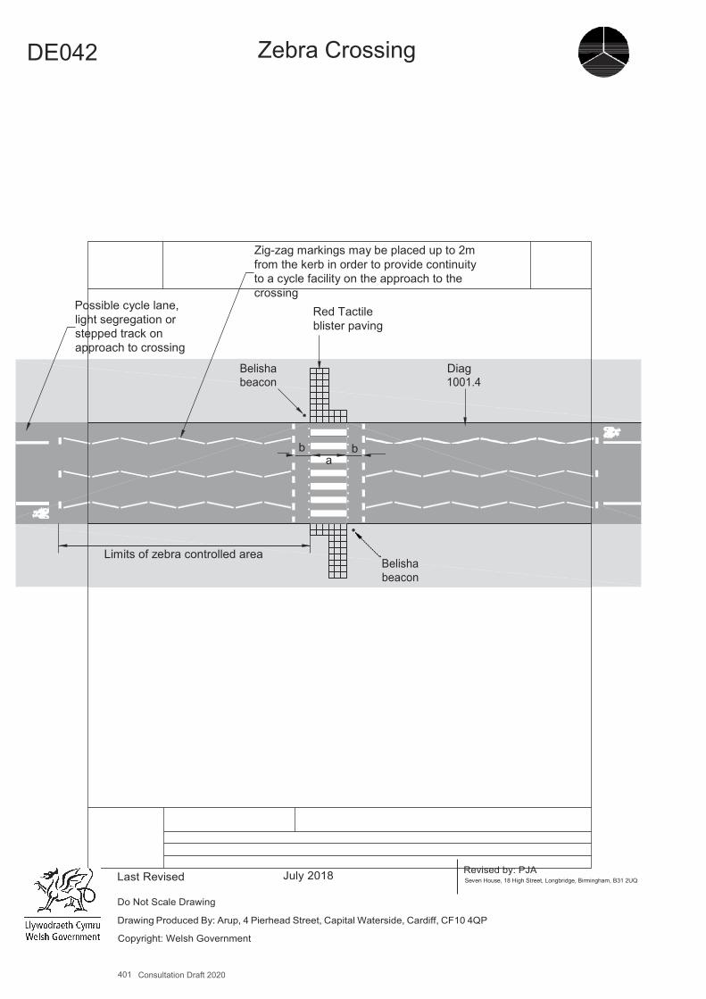
401 Consultation Draft 2020
A4
DE042 Zebra Crossing
Possible cycle lane, light segregation or stepped track on approach to crossing
Zig-zag markings may be placed up to 2m from the kerb in order to provide continuity to a cycle facility on the approach to the crossing
Red Tactile blister paving
Belisha beacon
Diag 1001.4
b b a
Limits of zebra controlled area Belisha beacon
Last Revised July 2018 Revised by: PJA Seven House, 18 High Street, Longbridge, Birmingham, B31 2UQ
Do Not Scale Drawing
Drawing Produced By: Arup, 4 Pierhead Street, Capital Waterside, Cardiff, CF10 4QP
Copyright: Welsh Government
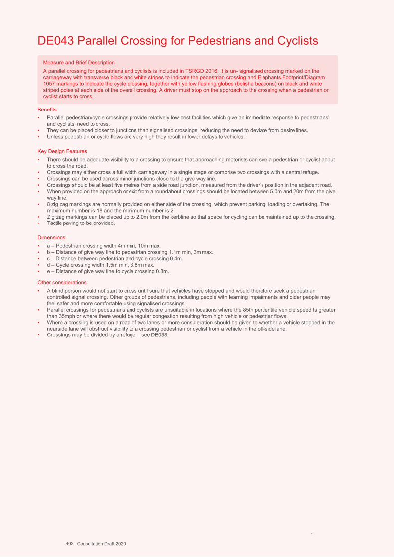
Design Guidance: Active Travel (Wales) Act 2013
360360 version 1 - DDececemembberer 20201414
DE043 Parallel Crossing for Pedestrians and Cyclists
Benefits ▪ Parallel pedestrian/cycle crossings provide relatively low-cost facilities which give an immediate response to pedestrians’
and cyclists’ need to cross. ▪ They can be placed closer to junctions than signalised crossings, reducing the need to deviate from desire lines. ▪ Unless pedestrian or cycle flows are very high they result in lower delays to vehicles.
Key Design Features ▪ There should be adequate visibility to a crossing to ensure that approaching motorists can see a pedestrian or cyclist about
to cross the road. ▪ Crossings may either cross a full width carriageway in a single stage or comprise two crossings with a central refuge. ▪ Crossings can be used across minor junctions close to the give way line. ▪ Crossings should be at least five metres from a side road junction, measured from the driver’s position in the adjacent road. ▪ When provided on the approach or exit from a roundabout crossings should be located between 5.0m and 20m from the give
way line. ▪ 8 zig zag markings are normally provided on either side of the crossing, which prevent parking, loading or overtaking. The
maximum number is 18 and the minimum number is 2. ▪ Zig zag markings can be placed up to 2.0m from the kerbline so that space for cycling can be maintained up to the crossing. ▪ Tactile paving to be provided.
Dimensions ▪ a – Pedestrian crossing width 4m min, 10m max. ▪ b – Distance of give way line to pedestrian crossing 1.1m min, 3m max. ▪ c – Distance between pedestrian and cycle crossing 0.4m. ▪ d – Cycle crossing width 1.5m min, 3.8m max. ▪ e – Distance of give way line to cycle crossing 0.8m.
Other considerations ▪ A blind person would not start to cross until sure that vehicles have stopped and would therefore seek a pedestrian
controlled signal crossing. Other groups of pedestrians, including people with learning impairments and older people may feel safer and more comfortable using signalised crossings.
▪ Parallel crossings for pedestrians and cyclists are unsuitable in locations where the 85th percentile vehicle speed Is greater than 35mph or where there would be regular congestion resulting from high vehicle or pedestrian flows.
▪ Where a crossing is used on a road of two lanes or more consideration should be given to whether a vehicle stopped in the nearside lane will obstruct visibility to a crossing pedestrian or cyclist from a vehicle in the off-side lane.
▪ Crossings may be divided by a refuge – see DE038.
-
Measure and Brief Description A parallel crossing for pedestrians and cyclists is included in TSRGD 2016. It is un- signalised crossing marked on the carriageway with transverse black and white stripes to indicate the pedestrian crossing and Elephants Footprint/Diagram 1057 markings to indicate the cycle crossing, together with yellow flashing globes (belisha beacons) on black and white striped poles at each side of the overall crossing. A driver must stop on the approach to the crossing when a pedestrian or cyclist starts to cross.
402 Consultation Draft 2020
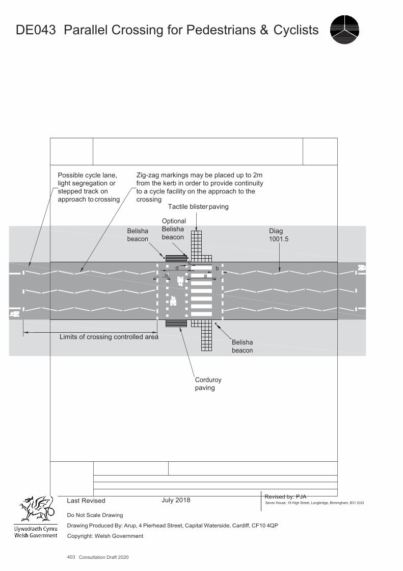
403 Consultation Draft 2020
A4
DE043 Parallel Crossing for Pedestrians & Cyclists
Possible cycle lane, light segregation or stepped track on approach to crossing
Zig-zag markings may be placed up to 2m from the kerb in order to provide continuity to a cycle facility on the approach to the crossing
Belisha beacon
Tactile blister paving
Optional Belisha beacon
Diag 1001.5
c d b
e a
Limits of crossing controlled area Belisha beacon
Corduroy paving
Last Revised
July 2018
Revised by: PJA Seven House, 18 High Street, Longbridge, Birmingham, B31 2UQ
Do Not Scale Drawing
Drawing Produced By: Arup, 4 Pierhead Street, Capital Waterside, Cardiff, CF10 4QP
Copyright: Welsh Government

DE044 Puffin and Ped-X Crossings
Benefits▪ Signalled crossings are preferred by visually impaired people, people with learning impairments and other groupsof
pedestrians including older people.▪ Puffin and Ped-X crossings include detector technology to extend the pedestrian crossing time so that people walking
more slowly are not disadvantaged. Parallel pedestrian/cycle crossings provide relatively low-cost facilities which give animmediate response to pedestrians’ and cyclists’ need tocross.
Key Design Features▪ Ped-X crossings with farside pedestrian signals are preferred by some users and are more suited to busy locations where
pedestrians may have difficulty seeing the nearside indicators due to crowding.▪ Signal-controlled pedestrian crossings may either cross a full width carriageway in a single stage or comprise two crossings
with a central refuge.▪ Crossings of single carriageways should preferably be single stage crossings with rapid push button response and recall
timings.▪ Two stage crossings are often staggered to ensure that pedestrians treat each stage as a separate crossing, but straight-
ahead divided crossings are much more convenient for pedestrians and should be used wherever possible. However, it willbe important to avoid ‘see-through’ where pedestrians could mistake a green man on the far crossing for a green man onthe near crossing.
▪ Two-stage straight ahead crossings can be achieved by using nearside pedestrian aspects, a wide central median orangling the crossings in preference to introducing a stagger.
▪ Where central waiting areas are created they should give maximum space and comfort to waiting users at peak times.▪ The aim should be to minimise the time that pedestrians have to wait at a crossing. Where a crossing has two stages
consideration should be given to including an advance call on the second crossing to minimise the time that a pedestrianhas to wait for the second crossing.
▪ It is important that sufficient time is allocated to allow all pedestrians (particularly older people) to cross the road in anefficient unhurried manner.
▪ Crossings should reflect desire lines, using angled crossings if they are appropriate.▪ Tactile paving and rotating cones for visually impaired users to be provided.▪ Audible signals should be considered but can be intrusive in residential areas.▪ 8 zig zag markings are normally provided on either side of the crossing, which prevent parking, loading or overtaking. The
maximum number is 18 and the minimum number is 2.▪ Zig zag markings can be placed up to 2m from the kerbline so that space for cycling can be maintained up to the crossing.
There should be adequate visibility to a crossing to ensure that approaching motorists can see a pedestrian or cyclist aboutto cross the road.
Dimensions▪ a - Crossing width 2.4m min, 10m max.▪ b - Distance of give way line to crossing studs 1.7m min, 3m max. a – Pedestrian crossing width 4m min, 10mmax.
Other considerations▪ Signal controlled crossings should generally be at least 20 metres from a side road junction.▪ On the approach to or exit from a roundabout a non-staggered signal-controlled crossing should be sited either at 20 metres
or more than 60 metres from the give way line. If the crossing is staggered, the crossing of the entry arm may be locatedbetween 20 metres and 60 metres from the give way line.
▪ The topography of the site needs to be such that the pedestrian detectors will operatesatisfactorily.▪ Care should be taken when locating signalled pedestrian crossings in close proximity to give-way junctions, particularly
roundabouts, where the presence of the vehicle signals could be misinterpreted as giving priority at the give-way junction.▪ Crossing points should remain free from street furniture and other clutter.▪ Signalised crossings should not be used where 85th percentile speeds exceed 50mph.
Further References▪ Department for Transport (2001) – Traffic Advisory Leaflet 1/01, Puffin PedestrianCrossing.▪ Department for Transport (2001) – Traffic Advisory Leaflet 1/02,The Installation of Puffin PedestrianCrossings.▪ Department for Transport (2005) – Traffic Advisory Leaflet 5/05, Pedestrian Facilities at Signal-ControlledJunctions.▪ Department for Transport (1995) – LTN 2/95, The Design of Pedestrian Crossings.
Measure and Brief DescriptionPuffin and Ped-X crossings are stand-alone signal-controlled pedestrian crossings. The traffic signal sequence is similar to a crossing facility at a signalised junction. Both types of crossing incorporate detection technology (usually infra-redwhich allows cancellation of the pedestrian demand if a pedestrian crosses after pressing the button but before the green man has activated. Additionally, the detectors are used to measure the speed at which pedestrians are crossing and automatically adjust the time allowed to cross the road. Puffin crossings have nearside pedestrian red and green aspects located as part of or above the push button unit, and located so that they can be seen at the same time as approaching traffic. A Ped-X crossing is a newer type, similar to a Puffin crossing in terms of signal sequence and detection, but with far side pedestrian signal aspects. ‘Countdown’ displays which show the time in seconds to the end of the crossing period, can be used with Ped-X crossings, but in this case, on-crossing detection cannot be used as the clearance period is fixed. Pelican crossings are an obsolescent type of crossing with a flashing amber for drivers and flashing green man crossing period, which must not be used for new installations.
404 Consultation Draft 2020
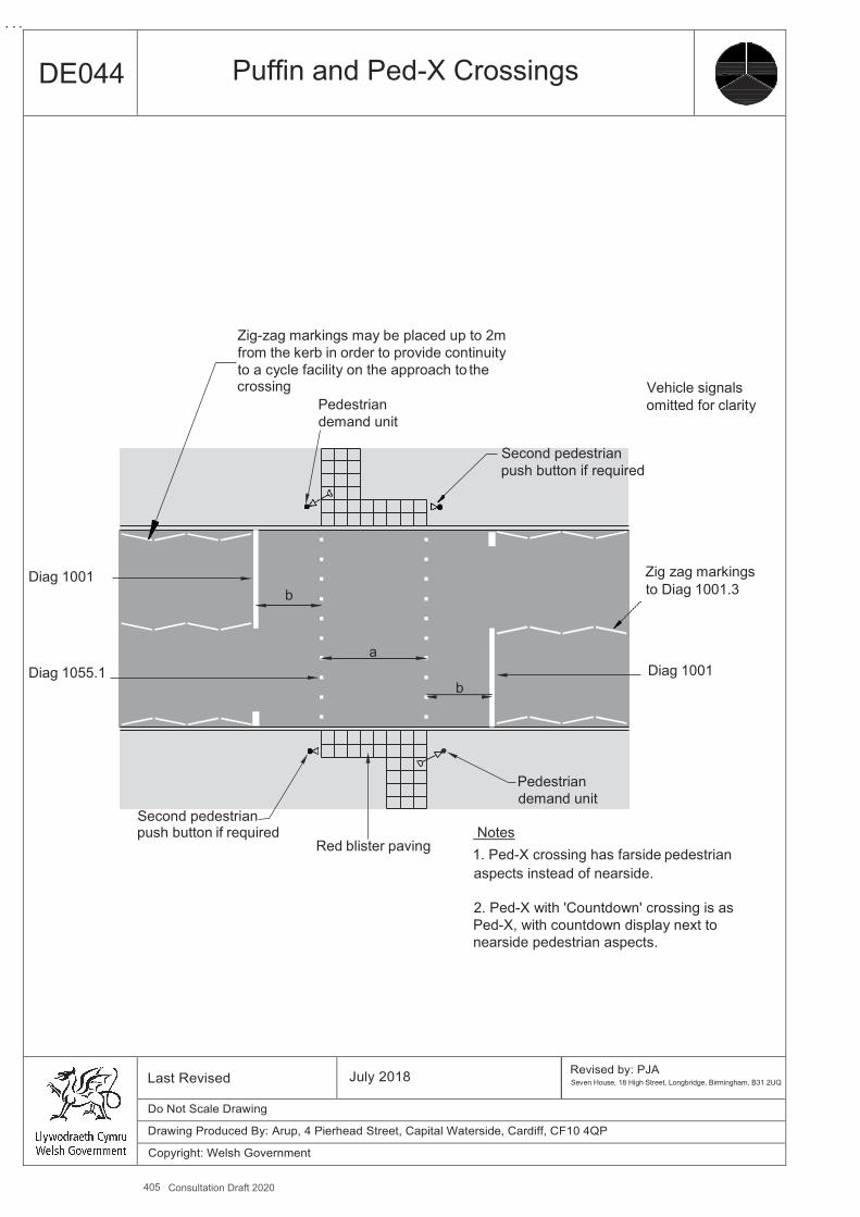
405 Consultation Draft 2020
A4
DE044 Puffin and Ped-X Crossings
Zig-zag markings may be placed up to 2m from the kerb in order to provide continuity to a cycle facility on the approach to the crossing Vehicle signals
Pedestrian omitted for clarity demand unit
Second pedestrian push button if required
Diag 1001 Zig zag markings b to Diag 1001.3
a
Diag 1055.1 Diag 1001 b
Pedestrian demand unit
Second pedestrian push button if required Notes
Red blister paving 1. Ped-X crossing has farside pedestrian aspects instead of nearside.
2. Ped-X with 'Countdown' crossing is as Ped-X, with countdown display next to nearside pedestrian aspects.
Last Revised July 2018 Revised by: PJA Seven House, 18 High Street, Longbridge, Birmingham, B31 2UQ
Do Not Scale Drawing
Drawing Produced By: Arup, 4 Pierhead Street, Capital Waterside, Cardiff, CF10 4QP
Copyright: Welsh Government
DE045 Toucan Crossing
Benefits ▪ Toucans provide a compact crossing facility catering for both pedestrians and cyclists in one location▪ Signalled crossings are preferred by visually impaired people, people with learning impairments and other groups of
pedestrians including older people.▪ Toucan crossings include detector technology to extend the pedestrian/cycle crossing time so that people travelling more
slowly are not disadvantaged.
Key Design Features ▪ Crossings with farside pedestrian/cycle signals are preferred by some users and are more suited to busy locations where
people may have difficulty seeing the nearside indicators due to crowding.▪ Toucan crossings may either cross a full width carriageway in a single stage or comprise two crossings with a central refuge.▪ Crossings of single carriageways should preferably be single stage crossings with rapid push button response and recall
timings.▪ Where a Toucan crossing is required on a wide road, a single-stage crossing should generally be provided for widths below
15m. For widths over 15m, the option of a single-stage crossing should be fully considered in the light of existing examples.▪ Staggered divided Toucan crossings very difficult for cyclists to use and should not normally be provided. Straight-ahead
divided crossings are much more convenient for cyclists and should be used in preference. However, it will be important toavoid ‘see-through’ where users could mistake a green signal on the far crossing for a green signal on the near crossing.
▪ Two-stage straight ahead crossings can be achieved by using nearside pedestrian/cycle aspects, a wide central median orangling the crossings in preference to introducing a stagger.
▪ Where central waiting areas are created they should give maximum space and comfort to waiting users at peak times.▪ The aim should be to minimise the time that pedestrians and cyclists have to wait at a crossing. Where a crossing has
two stages consideration should be given to including an advance call on the second crossing to minimise the time that apedestrian or cyclist has to wait for the second crossing.
▪ It is important that sufficient is time allocated to allow all pedestrians (particularly older people) to cross the road in anefficient unhurried manner.
▪ Designs should also take account of the demand for cyclists wishing to join or leave the carriageway at the crossing.▪ Crossings should reflect desire lines, using angled crossings if they are appropriate.▪ Tactile paving and rotating cones for visually impaired users to be provided.▪ Audible signals should be considered but can be intrusive in residential areas.▪ 8 zig zag markings are normally provided on either side of the crossing, which prevent parking, loading or overtaking. The
maximum number is 18 and the minimum number is 2.▪ Zig zag markings can be placed up to 2.0m from the kerbline so that space for cycling can be maintained up to the crossing.
Dimensions ▪ a - Minimum recommended width of crossing is 4m, although where usage is low a 3m width is allowed. Maximum permitted
width is 10m.▪ b - Distance of stop line to crossing studs 1.7m min, 3m max. a - Crossing width 2.4m min, 10m max.
Other considerations ▪ Signal controlled crossings should generally be at least 20 metres from a side road junction.▪ On the approach to or exit from a roundabout a non-staggered signal-controlled crossing should be sited either at 20 metres
or more than 60 metres from the give way line.▪ When crossings are located close to a signal controlled junction, consideration should be given to linking the signals to the
junction signals. The distance at which this should be considered will depend on traffic conditions but 100 metres is likely tobe the minimum distance at which linking is required.
▪ The topography of the site needs to be such that the pedestrian detectors will operate satisfactorily.▪ Toucans that have a long delay time before giving a green to cyclists cause frustration and can lead to frequent attempts to
cross before the green light appears. Detection systems that identify approaching pedestrians and cyclists can speed up thecountdown timer and reduce waiting times on the side of a busy or fast moving road.
▪ Crossing points should remain free from street furniture and other clutter.▪ Signalised crossings should not be used where 85th percentile speeds exceed 50mph.
Further References
▪ Department for Transport (2005) – Traffic Advisory Leaflet 5/05, Pedestrian Facilities at Signal-Controlled Junctions.▪ Department for Transport (1995) – LTN 2/95, The Design of Pedestrian Crossings.
-
Measure and Brief Description A Toucan crossing is a stand-alone signal-controlled pedestrian and cycle crossing. The traffic signal sequence is similar to a crossing facility at a signalised junction. Toucan crossings incorporate detection technology (usually infra-red) which allows cancellation of the pedestrian/cycle demand if a person crosses after pressing the button but before the green man has activated. Additionally, the detectors are used to measure the speed at which people are crossing and automatically adjust the time allowed to cross the road. Toucan crossings have nearside pedestrian/cycle red and green aspects located as part of or above the push button unit and located so that they can be seen at the same time as approaching traffic; farside aspects can also be used if preferred. Toucan crossings are used where there is a significant demand for cycle crossing movements over busy and faster roads, and a priority crossing (DE037) or parallel crossing for pedestrians and cyclists (DE043) is not suitable.
406 Consultation Draft 2020
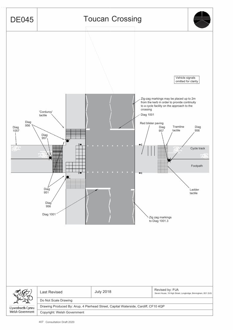
407 Consultation Draft 2020
A4
DE045 Toucan Crossing
Diag 1057
Diag 956
'Corduroy' tactile
Diag 957
Diag 951
Diag 956
Diag 1001
Vehicle signals omitted for clarity
Zig-zag markings may be placed up to 2m from the kerb in order to provide continuity to a cycle facility on the approach to the crossing
Diag 1001
Red blister paving Diag Tramline Diag 957 tactile 956
Cycle track
Footpath
Ladder tactile
Zig zag markings to Diag 1001.3
Last Revised July 2018 Revised by: PJA Seven House, 18 High Street, Longbridge, Birmingham, B31 2UQ
Do Not Scale Drawing
Drawing Produced By: Arup, 4 Pierhead Street, Capital Waterside, Cardiff, CF10 4QP
Copyright: Welsh Government
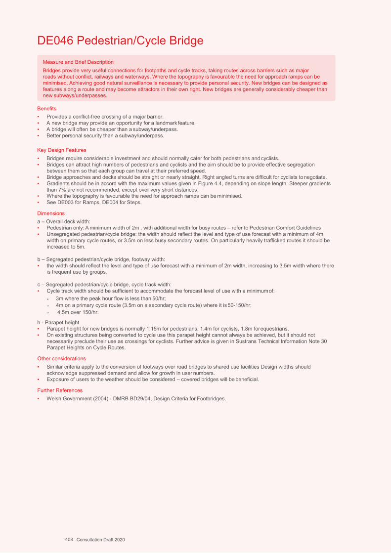
DE046 Pedestrian/Cycle Bridge
Benefits ▪ Provides a conflict-free crossing of a major barrier. ▪ A new bridge may provide an opportunity for a landmark feature. ▪ A bridge will often be cheaper than a subway/underpass. ▪ Better personal security than a subway/underpass.
Key Design Features ▪ Bridges require considerable investment and should normally cater for both pedestrians and cyclists. ▪ Bridges can attract high numbers of pedestrians and cyclists and the aim should be to provide effective segregation
between them so that each group can travel at their preferred speed. ▪ Bridge approaches and decks should be straight or nearly straight. Right angled turns are difficult for cyclists to negotiate. ▪ Gradients should be in accord with the maximum values given in Figure 4.4, depending on slope length. Steeper gradients
than 7% are not recommended, except over very short distances. ▪ Where the topography is favourable the need for approach ramps can be minimised. ▪ See DE003 for Ramps, DE004 for Steps.
Dimensions a – Overall deck width: ▪ Pedestrian only: A minimum width of 2m , with additional width for busy routes – refer to Pedestrian Comfort Guidelines ▪ Unsegregated pedestrian/cycle bridge: the width should reflect the level and type of use forecast with a minimum of 4m
width on primary cycle routes, or 3.5m on less busy secondary routes. On particularly heavily trafficked routes it should be increased to 5m.
b – Segregated pedestrian/cycle bridge, footway width: ▪ the width should reflect the level and type of use forecast with a minimum of 2m width, increasing to 3.5m width where there
is frequent use by groups.
c – Segregated pedestrian/cycle bridge, cycle track width: ▪ Cycle track width should be sufficient to accommodate the forecast level of use with a minimum of:
3m where the peak hour flow is less than 50/hr; 4m on a primary cycle route (3.5m on a secondary cycle route) where it is 50-150/hr; 4.5m over 150/hr.
h - Parapet height ▪ Parapet height for new bridges is normally 1.15m for pedestrians, 1.4m for cyclists, 1.8m for equestrians. ▪ On existing structures being converted to cycle use this parapet height cannot always be achieved, but it should not
necessarily preclude their use as crossings for cyclists. Further advice is given in Sustrans Technical Information Note 30 Parapet Heights on Cycle Routes.
Other considerations ▪ Similar criteria apply to the conversion of footways over road bridges to shared use facilities Design widths should
acknowledge suppressed demand and allow for growth in user numbers. ▪ Exposure of users to the weather should be considered – covered bridges will be beneficial.
Further References ▪ Welsh Government (2004) - DMRB BD29/04, Design Criteria for Footbridges.
Measure and Brief Description Bridges provide very useful connections for footpaths and cycle tracks, taking routes across barriers such as major roads without conflict, railways and waterways. Where the topography is favourable the need for approach ramps can be minimised. Achieving good natural surveillance is necessary to provide personal security. New bridges can be designed as features along a route and may become attractors in their own right. New bridges are generally considerably cheaper than new subways/underpasses.
408 Consultation Draft 2020
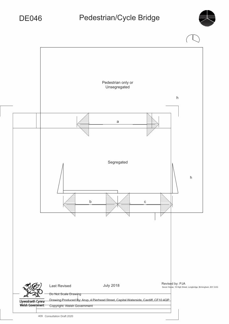
409 Consultation Draft 2020
A4
DE046
Pedestrian/Cycle Bridge
Pedestrian only or Unsegregated
h
a
Segregated
h
b c
Last Revised July 2018 Revised by: PJA Seven House, 18 High Street, Longbridge, Birmingham, B31 2UQ
Do Not Scale Drawing
Drawing Produced By: Arup, 4 Pierhead Street, Capital Waterside, Cardiff, CF10 4QP
Copyright: Welsh Government
DE047 Subway/Underpass
Benefits ▪ Provides a conflict free crossing of a major barrier. ▪ Avoids exposure to the weather. ▪ The longitudinal profile of an underpass (down then up) is more comfortable for cyclists than bridges with approach ramps.
Key Design Features ▪ Subways/underpasses require considerable investment and should normally cater for both pedestrians and cyclists. ▪ Subways/underpasses can attract high numbers of pedestrians and cyclists and the aim should be to provide effective
segregation between them so that each group can travel at their preferred speed. ▪ Approaches and the structures themselves should be straight or nearly straight. Right angled turns are difficult for cyclists to
negotiate. ▪ Gradients should be in accord with the maximum values given in Figure 4.4, depending on slope length. Steeper gradients
than 7% are not recommended, except over very short distances. ▪ Where the topography is favourable the need for approach ramps can be minimised. ▪ Lighting should be provided and be vandal proof. ▪ Corners and recesses should be avoided, with the exits being visible to users on entry. ▪ Natural lighting should be maximised by the use of generous widths, angled sides to the structure and light wells on longer
crossings. ▪ See DE003 for Ramps, DE004 for Steps.
Dimensions ▪ Subways for pedestrians require headroom (h1) of at least 2.3m (2.6m for lengths over 23m) and a width (w1) of 3m (2.3m
for light use). ▪ Subways for use by cyclists require headroom (h1) of 2.4m (2.7m for lengths over 23m) and width (w1) of at least 4m (3m
for light use) if unsegregated. ▪ Segregated: the width for pedestrians (w2) should be at least 2m, the cycle track (w3) 2.5m and the margin strip (w4) 0.5m.
Headroom for cyclists (h2) and pedestrians (h3) as above. ▪ A headroom of 3.7m is required if the routes is to be used by mounted equestrians.
Other considerations ▪ The headroom in existing pedestrian subways is typically 2.3m; the slightly sub-standard height for cyclists should not lead
to automatic rejection of a proposal to permit cycling. There are many examples of structures on public roads and on traffic free routes with headroom well below 2.4m, which operate without incident for cyclists. Any restricted headroom should be clearly signed. The ‘cyclists dismount’ sign should not be used.
▪ Exit must be visible on entering the subway. ▪ Generous headroom and width will be highly beneficial in terms of subjective safety, natural surveillance and personal
security. ▪ Barriers to slow cyclists should not normally be used as these can restrict access for non-standard cycles.
Further References ▪ Welsh Government (1993) - DMRB TD36/93, Subways for Pedestrians and Pedal Cyclists Layout and Dimensions.
Measure and Brief Description Subways/underpasses can provide very useful connections for footpaths and cycle tracks, taking routes across barriers such as at major roads without conflict, railways and waterways. Where the topography is favourable the need for approach ramps can be minimised. Achieving good natural surveillance is necessary to provide personal security. This option may involve the conversion of an existing pedestrian subway or an underpass provided for private access.
410 Consultation Draft 2020
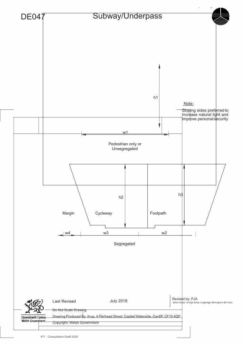
411 Consultation Draft 2020
A4
DE047
Subway/Underpass
h1 Note: Sloping sides preferred to increase natural light and improve personal security
w1
Pedestrian only or Unsegregated
h2 h3
Margin Cycleway Footpath
w4 w3 w2
Segregated
Last Revised July 2018 Revised by: PJA Seven House, 18 High Street, Longbridge, Birmingham, B31 2UQ
Do Not Scale Drawing
Drawing Produced By: Arup, 4 Pierhead Street, Capital Waterside, Cardiff, CF10 4QP
Copyright: Welsh Government
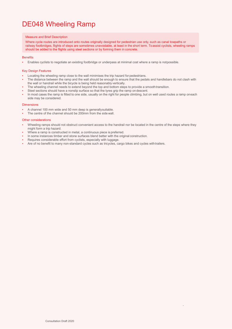
412
DE048 Wheeling Ramp
Benefits ▪ Enables cyclists to negotiate an existing footbridge or underpass at minimal cost where a ramp is not possible.
Key Design Features ▪ Locating the wheeling ramp close to the wall minimises the trip hazard for pedestrians. ▪ The distance between the ramp and the wall should be enough to ensure that the pedals and handlebars do not clash with
the wall or handrail while the bicycle is being held reasonably vertically. ▪ The wheeling channel needs to extend beyond the top and bottom steps to provide a smooth transition. ▪ Steel sections should have a nonslip surface so that the tyres grip the ramp on descent. ▪ In most cases the ramp is fitted to one side, usually on the right for people climbing, but on well used routes a ramp on each
side may be considered.
Dimensions ▪ A channel 100 mm wide and 50 mm deep is generally suitable. ▪ The centre of the channel should be 200mm from the side wall.
Other considerations ▪ Wheeling ramps should not obstruct convenient access to the handrail nor be located in the centre of the steps where they
might form a trip hazard. ▪ Where a ramp is constructed in metal, a continuous piece is preferred. ▪ In some instances timber and stone surfaces blend better with the original construction. ▪ Requires considerable effort from cyclists, especially with luggage. ▪ Are of no benefit to many non-standard cycles such as tricycles, cargo bikes and cycles with trailers.
-
Measure and Brief Description Where cycle routes are introduced onto routes originally designed for pedestrian use only, such as canal towpaths or railway footbridges, flights of steps are sometimes unavoidable, at least in the short term. To assist cyclists, wheeling ramps should be added to the flights using steel sections or by forming them in concrete.
Consultation Draft 2020
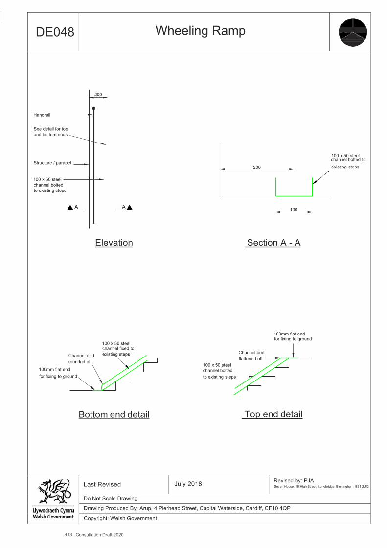
413 Consultation Draft 2020
A4
DE048 Wheeling Ramp
200
Handrail
See detail for top and bottom ends
100 x 50 steel Structure / parapet
channel bolted to
200 existing steps
100 x 50 steel channel bolted to existing steps
A A 100
Elevation Section A - A
100mm flat end for fixing to ground
100 x 50 steel channel fixed to
Channel end existing steps Channel end
rounded off flattened off 100 x 50 steel
100mm flat end channel bolted for fixing to ground to existing steps
Bottom end detail Top end detail
Last Revised July 2018 Revised by: PJA Seven House, 18 High Street, Longbridge, Birmingham, B31 2UQ
Do Not Scale Drawing
Drawing Produced By: Arup, 4 Pierhead Street, Capital Waterside, Cardiff, CF10 4QP
Copyright: Welsh Government
DE049 Unmarked Informal Junction
Benefits ▪ Reduced delays to all users, particularly during off-peak periods ▪ Good safety record ▪ Improved public realm, enhancing the attractiveness of urban centres
Key Design Features ▪ Junctions of this type should be designed to suit local circumstances – standardised solutions are not appropriate. ▪ Motor vehicle paths should be limited to a single lane on entries and exits. ▪ General lane widths should be kept as narrow as possible but separate provision may be made for cyclists so that they are
able to pass queuing vehicles on the junction approaches. ▪ Speeds on the approaches should be around 20mph. ▪ Traffic signal crossings should not be used on the approaches to the junction since green signals can reinforce drivers’
sense of priority over pedestrians. ▪ Informal (or zebra/parallel pedestrian and cycle crossings) should be provided on desire lines. ▪ Crossings can also be made available to cyclists so that they can travel around the junction via cycle tracks or shared paths
outside the carriageway. ▪ Crossings should be paved in a material which contrasts with the general carriageway, with tactile paving. ▪ Central islands or median strips at crossings help pedestrians and cyclists to cross and make it more likely that drivers will
cede priority (see DE038 and DE041). ▪ Paving materials that are visibly different from standard bituminous surfacing will help to reinforce the distinctiveness of the
place. ▪ A range of kerb heights can be used between crossing points. Flush or very low kerbs will require tactile paving.
Dimensions ▪ Overall dimensions vary but are typically around 25m to 40m across.
Other considerations ▪ This type of junction works best in urban areas with high numbers of pedestrians and general activity, particularly town and
city centres. ▪ They can form part of a wider public realm/shared space scheme, but can also be provided in isolation. ▪ Visually impaired people will prefer signalised crossings to zebra and informal crossings.
-
Measure and Brief Description Junctions in urban areas, even on relatively busy routes, can be designed without defined priority, requiring all road users to slow down and engage/negotiate with other road users. The application of these ‘shared space’ principles is becoming increasingly common and has been demonstrated to be effective in terms of traffic capacity and safety on four-arm junctions with peak period flows in excess of 2,500 vehicles per hour. Examples include junctions in the centre of Coventry, in Poynton in Cheshire and in Hackney (see photos). This type of junction can work well for pedestrians and cyclists.
414 Consultation Draft 2020

415 Consultation Draft 2020
A4
DE049 Unmarked Informal Junction
Poynton, Cheshire - Double Junction, each designed to encourage circulatory priority, with courtesy crossings, carrying circa 26,000 vehicles per day overall
Leonard Circus, London - Uncontrolled junction with no designated crossings
Coventry - Plain uncontrolled junction with crossings
Last Revised July 2018 Revised by: PJA Seven House, 18 High Street, Longbridge, Birmingham, B31 2UQ
Do Not Scale Drawing
Drawing Produced By: Arup, 4 Pierhead Street, Capital Waterside, Cardiff, CF10 4QP
Copyright: Welsh Government
L374
DE050 Advanced Stop Line
Benefits ▪ Feeder lanes allow cyclists to bypass waiting traffic, and get to the ASL reservoir at the head of the queue. Cyclists can
position themselves where they are visible and in the correct turning lane. This is particularly helpful for cyclists making right turns and where there is a separately signalled left turn and cyclists wait to go ahead.
▪ ASLs can be used to a safe area for a cyclist to merge back into the carriageway from a cycle track. ▪ The ASL reservoir provides cyclists with an area free from exhaust fumes in which to wait. ▪ ASLs improve the comfort of pedestrians, by setting waiting motor traffic back from the pedestrian crossing.
Key Design Features ▪ The design of ASLs must be site-specific. Consideration should be given to factors such as the turning traffic volumes and
dominant cycle movements, signal staging, location and number of approach lanes, and vehicle swept paths. ▪ Feeder lanes should be provided wherever possible and should preferably be mandatory, although a wide advisory cycle
lane, accepting that some vehicles may encroach, may be better than a narrow mandatory lane. ▪ ASLs can also operate without feeder lanes, with ‘gate’ markings to diagram 1001.2A, but the benefit of an ASL is much
reduced if no lead in lane is provided, since less confident cyclists will not try to reach the reservoir. ▪ Feeder lanes are normally located on the nearside. Centre and offside feeder lanes can also be provided to help cyclists
make specific movements. For example where there is a heavy left-turning traffic movement which conflicts with a dominant ahead or right cycle movement, the feeder lane should be positioned between the left and ahead traffic lanes.
▪ Feeder lanes between traffic lanes need to be wider and this is generally achievable by narrowing the traffic lanes. Continuity of cycle lanes feeding ASLs should be maintained, with traffic having to cross the cycle lane to access the left turn lane.
▪ On approaches toASLs, it is important that detection loops are positioned so that they cover the approach cycle lanes as well as the general traffic lanes. Often this is not the case, resulting in approaching cyclists not being detected. Similar considerations apply to above ground detection.
▪ Advanced stop lines can be partial width or have staggered stop lines. This is useful where right turns are not permitted (for cyclists or all vehicles), there are multiple right-turning lanes or tracking of vehicle movements into the arm of the junction shows that they would encroach on the ASL reservoir if it were full-width. There is some evidence that drivers less likely to encroach into partial ASLs.
▪ Coloured surfacing can also be used to emphasise the reservoir, which can be full or part width.
Dimensions ▪ The recommended minimum length of the reservoir for cyclists is 5.0m - TSRGD permits a minimum of 4.0m. Longer
reservoirs may be considered to satisfy demand, up to a maximum of 7.5m (or 10.0m with special authorization). ▪ Nearside feeder lanes should normally be a minimum of 1.5m wide, and wider where possible. The absolute minimum width
is 1.2m. ▪ Central and offside feeder lanes should be a minimum of 2m wide – absolute minimum 1.5m. ▪ General traffic lanes may be reduced to a minimum of 2.5m, which allows motor traffic not to block or encroach on thecycle
lane.
Other considerations ▪ An ‘early start’ signal phase for cyclists can be used, using a low-level cycle signal (primary) and/or a 4th aspect ‘cycle filter’
(primary or secondary). It enables cyclists waiting in the reservoir to start (typically up to 7 seconds) ahead of other traffic and to clear locations of potential conflict with traffic on the same arm (e.g. overtaking and turning left) or opposing traffic streams.
▪ ASLs have little or no effect on capacity if the number of all-purpose traffic lanes remains unaltered. ▪ Care should also be taken at signals where there are large numbers of HGVs turning left because of the potential for cyclists
to move into the driver’s blind spot.
Further References ▪ Department for Transport (2003) – Traffic Signs Manual
-
Measure and Brief Description An Advanced Stop Line (ASL) enables cyclists to take up an appropriate position in the ‘reservoir’, or waiting area between the two stop lines, for their intended manoeuvre ahead of general traffic, before the signals change to green. A cycle feeder lane should normally be provided, which will enable cyclists to pass queuing motor traffic on the approach to the stop line. They are established practice in most highway authorities and some now have a presumption to install ASLs at all signalled junctions. ASLs may not resolve all problems for cyclists at traffic signals however; they are of no value when signals are on green, and so may be less suitable on junction approaches which run during most of a signal cycle. A large, complex, high speed motor vehicle-dominated junction will not be made cycle-friendly by the provision of ASLs.
416 Consultation Draft 2020
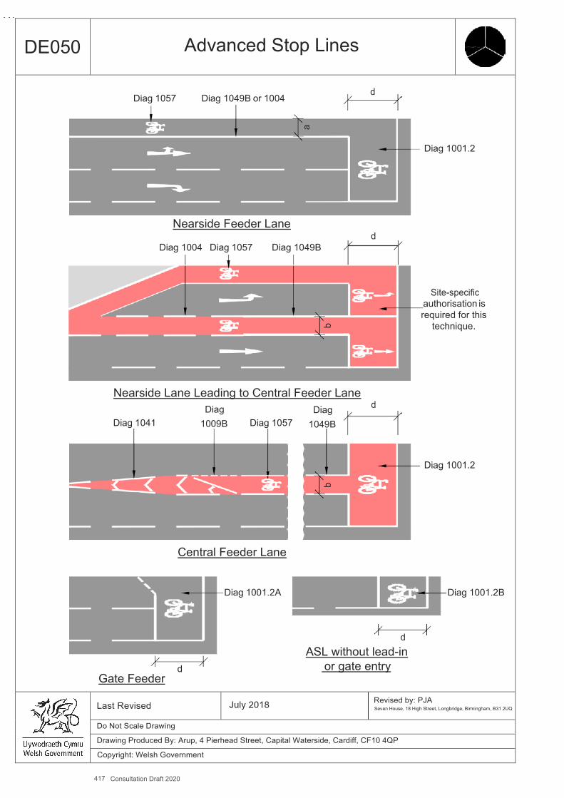
417 Consultation Draft 2020
A4
a
b b
DE050 Advanced Stop Lines
Diag 1057 Diag 1049B or 1004 d
Diag 1001.2
Nearside Feeder Lane d
Diag 1004 Diag 1057 Diag 1049B
Site-specific authorisation is
required for this technique.
Nearside Lane Leading to Central Feeder Lane Diag Diag d
Diag 1041 1009B Diag 1057 1049B
Diag 1001.2
Central Feeder Lane
Diag 1001.2A Diag 1001.2B
d ASL without lead-in
d or gate entry Gate Feeder
Last Revised July 2018 Revised by: PJA Seven House, 18 High Street, Longbridge, Birmingham, B31 2UQ
Do Not Scale Drawing
Drawing Produced By: Arup, 4 Pierhead Street, Capital Waterside, Cardiff, CF10 4QP
Copyright: Welsh Government

L376
DE051 Cycle Bypass at Traffic Signals
Benefits ▪ reduce delays to cyclists and offer time advantages compared to other traffic. ▪ formalise (and legalise) common cyclist behaviour. ▪ enable cyclists to maintain momentum, improving comfort. ▪ increases permeability where it enables cyclists to make manoeuvres that are prohibited for other modes.
Key Design Features ▪ Bypasses should be built within the carriageway so as not to impede pedestrian flows, but where this is impractical the
bypass can be merged into a cycle track at or close to footway level. ▪ The design should make it clear if the facility is to be used in one or both directions. ▪ Cycle bypasses may, or may not, have their own set of signals phased to give early starts, or separate cycle phases. They
may simply end at a Give Way line, discharge into a lane or track, or merge into general traffic. ▪ Loop detection on the approaches, and infra-red technology to detect waiting cyclists will help to speed up sequencing of
traffic signals ahead. ▪ Careful design is required at pedestrian crossing locations.
Dimensions ▪ Minimum 2.0m wide track (a), 1.5m for short lengths. ▪ Margin strip (b) min 0.5m.
Other considerations ▪ Bypasses need to be designed to accommodate a variety of cycle types, and also be accessible to mini road sweepers.
Poorly-accessible facilities will collect litter/broken glass and become unusable. ▪ A protected entry to the carriageway is preferred.
-
Measure and Brief Description Where space and level of pedestrian use allow, it will be beneficial to cyclists to provide a slip off in advance of a signalised junction, leading to a short section of cycle track that enables the cyclist to bypass the red signal. This may be used to assist cyclists either to turn left or to continue straight ahead at the top of a T junction. Cycle bypasses can also be used as approach routes to cycle and pedestrian crossings in order to facilitate difficult manoeuvres (e.g. right turns) or to make manoeuvres which are prohibited to other traffic.
418 Consultation Draft 2020
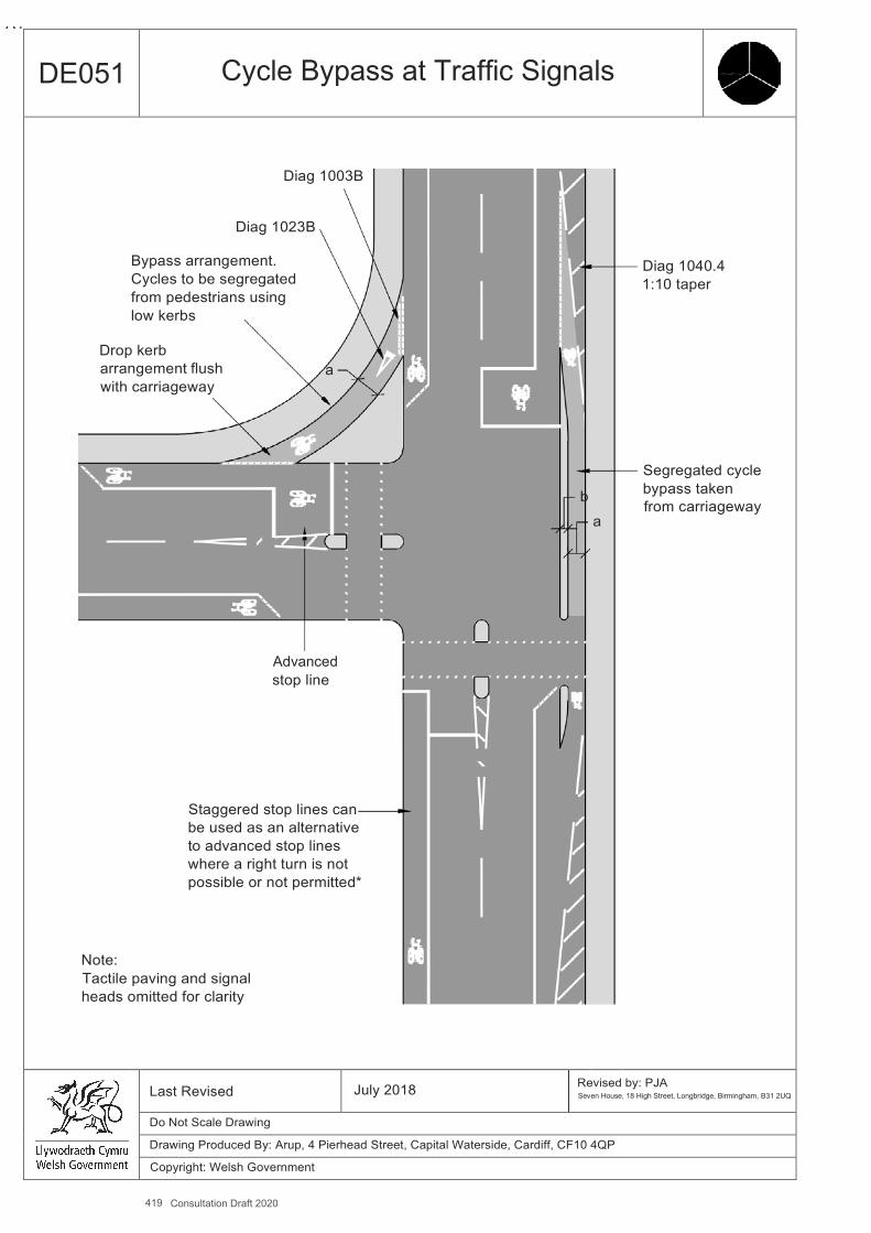
419 Consultation Draft 2020
A4
DE051 Cycle Bypass at Traffic Signals
Diag 1003B
Diag 1023B
Bypass arrangement. Cycles to be segregated from pedestrians using low kerbs
Diag 1040.4 1:10 taper
Drop kerb arrangement flush a with carriageway
b
a
Segregated cycle bypass taken from carriageway
Advanced stop line
Staggered stop lines can be used as an alternative to advanced stop lines where a right turn is not possible or not permitted*
Note: Tactile paving and signal heads omitted for clarity
Last Revised July 2018 Revised by: PJA Seven House, 18 High Street, Longbridge, Birmingham, B31 2UQ
Do Not Scale Drawing
Drawing Produced By: Arup, 4 Pierhead Street, Capital Waterside, Cardiff, CF10 4QP
Copyright: Welsh Government
L378
DE052 Cycle Lanes Through Signalised Junction
Benefits ▪ Help to guide cyclists. ▪ Raise the awareness of motorists that a junction forms part of a recognised cycle route. ▪ They are particularly beneficial for large and complex junctions.
Key Design Features ▪ Route markings should comprise Diag 1010 markings or alternatively advisory cycle lane markings (diag 1004). ▪ Consider highlighting with coloured surfacing.
Dimensions ▪ a - Width of cycle lane on approaches refer to DE013 and DE014. ▪ b - Width of cycle lane through junction to be at least 0.5m wider than the approach cycle lane, min 2m is recommended
where movements are generally straight ahead, and traffic passes cyclists on the riders’ right. ▪ Minimum width lanes of 2.5m are recommended where traffic can be moving on both sides of the cyclist.
Other considerations ▪ Where cyclists have several cross cutting desire lines through a junction, attempting to mark these may be confusing and
counter-productive. ▪ Route markings through junctions will be subject to high levels of wear and will require maintenance.
-
Measure and Brief Description A cycle lane marked through a signalised junction provides a visible indication of route continuity and increases drivers’ awareness of key cycle movements. They are used to indicate route continuity and protect space for cyclist desire lines through major junctions on cycle routes.
420 Consultation Draft 2020
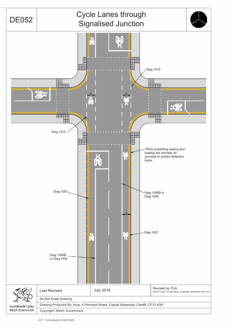
421 Consultation Draft 2020
A4
DE052 Cycle Lanes through Signalised Junction
Diag 1010
Diag 1057
Diag 1049B or Diag 1004
a
a
a
Diag 1010
TROs prohibiting waiting and loading will normally be provided to protect detection loops.
Diag 1049B or Diag 1004
Diag 1057
Last Revised July 2018 Revised by: PJA Seven House, 18 High Street, Longbridge, Birmingham, B31 2UQ
Do Not Scale Drawing
Drawing Produced By: Arup, 4 Pierhead Street, Capital Waterside, Cardiff, CF10 4QP
Copyright: Welsh Government

Design Guidance: Active Travel (Wales) Act 2013
A
380380 vvererssiionon 11 -- DDececemembberer 20201414
DE 053, 54, 55 Two Stage Right Turns at Traffic Signals
Benefits ▪ Cyclists able to make a safe right turn off a busy road, without having to weave across traffic lanes.
Key Design Features ▪ The waiting area can be marked with a cycle symbol (Diag 1057) and right turn arrow (Diag 1059), backed with coloured
surfacing if needed. ▪ The waiting area must be clear of any pedestrian crossing on the side road and sufficiently far back from ahead traffic on the
main road for cyclists waiting there to feel safe. It should be clear of any cycle lane across the junction. ▪ Waiting area should to be of sufficient size for the number of cyclists waiting to turn. ▪ Cyclists rely on the secondary signal on the side road to know when they can make the second stage of the turn, so this
must be located where cyclists can see it.
Dimensions ▪ Waiting area to be marked at centre of nearside approach lane.
Other considerations ▪ Detection of waiting cycles will be necessary if the side road flow is insufficient to call the stage. ▪ Cyclists can choose to make a two stage right turn at junctions where such provision is not marked. ▪ An ‘early start’ signal phase for cyclists using low level signals/4th aspect cycle filter can be used to reduce conflict with left
turning traffic – see DE050. ▪ This is an unfamiliar manoeuvre to most UK cyclists and a public information programme should be considered. ▪ Surface markings at junctions will be subject to high levels of wear and will require maintenance.
Measure and Brief Description Based on a standard feature at junctions in Denmark and other countries, this design provides for cyclists turning right at a a multi-lane approach to a signalised junction, where the speed and volume of motor traffic makes the execution of a conventional right turn hazardous and unpleasant, even when an ASL is provided. Provision is made for cyclists to pull in to the side road on their left and wait there until the side road has a green light, at which point cyclists can make a straight across movement to complete their right turn.
422 Consultation Draft 2020
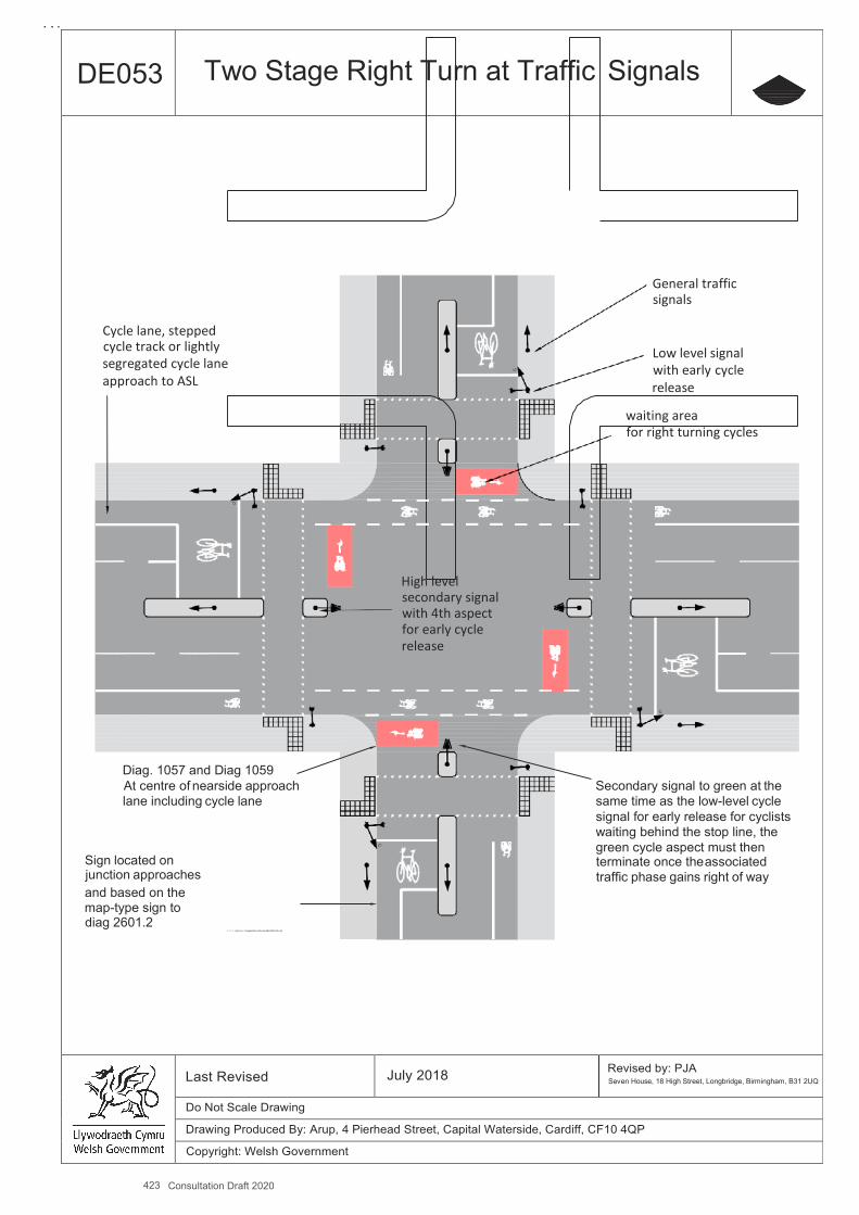
423 Consultation Draft 2020
A4
DE053 Two Stage Right Turn at Traffic Signals
General traffic signals
Cycle lane, stepped cycle track or lightly Low level signal segregated cycle lane with early cycle approach to ASL release
waiting area for right turning cycles
High level secondary signal with 4th aspect for early cycle release
Diag. 1057 and Diag 1059 At centre of nearside approach Secondary signal to green at the lane including cycle lane same time as the low-level cycle
signal for early release for cyclists waiting behind the stop line, the green cycle aspect must then
Sign located on terminate once the associated junction approaches traffic phase gains right of way and based on the map-type sign to diag 2601.2
..\..\..\..\..\johnmc~1\appdata\local\temp\a$c34597afe.dib
Last Revised July 2018 Revised by: PJA Seven House, 18 High Street, Longbridge, Birmingham, B31 2UQ
Do Not Scale Drawing
Drawing Produced By: Arup, 4 Pierhead Street, Capital Waterside, Cardiff, CF10 4QP
Copyright: Welsh Government
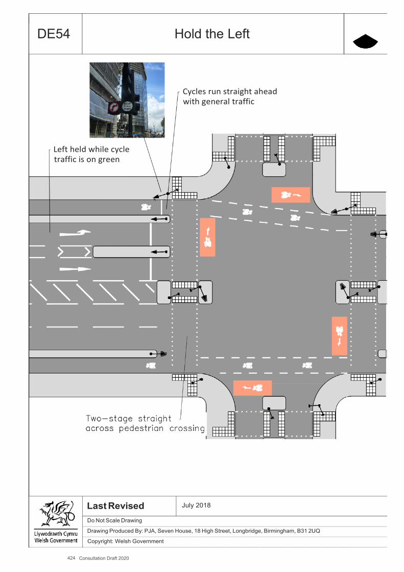
424 Consultation Draft 2020
A4
DE54 Hold the Left
Cycles run straight ahead with general traffic
Left held while cycle traffic is on green
Last Revised Do Not Scale Drawing
July 2018
Drawing Produced By: PJA, Seven House, 18 High Street, Longbridge, Birmingham, B31 2UQ
Copyright: Welsh Government
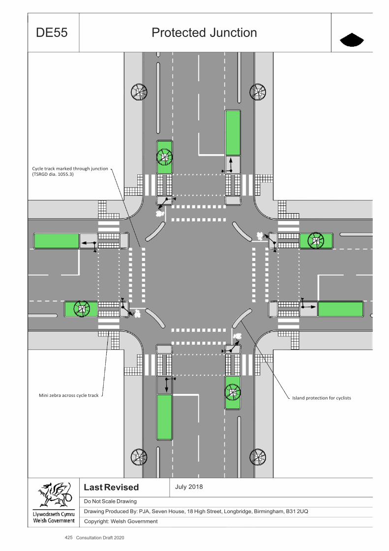
425 Consultation Draft 2020
A4
DE55 Protected Junction
Cycle track marked through junction (TSRGD dia. 1055.3)
Mini zebra across cycle track
Island protection for cyclists
Last Revised Do Not Scale Drawing
July 2018
Drawing Produced By: PJA, Seven House, 18 High Street, Longbridge, Birmingham, B31 2UQ
Copyright: Welsh Government

426
Design Guidance: Active Travel (Wales) Act 2013
382382 version 1 - DDececemembberer 20201414
DE056 Mini Roundabout
Benefits ▪ Single circulatory carriageway puts cyclists in drivers’ line of sight. ▪ Traffic calming effect, especially where they are installed on raised tables. ▪ Slower speeds which aids cyclists’ comfort and safety, especially those wanting to turn right. ▪ Potential reduction in traffic delay compared to priority junctions.
Key Design Features ▪ Single lane entries and exits. ▪ Domed central roundel. ▪ Deflection of traffic. ▪ Any cycle lanes on approaches should end 20-30m in advance of the give way line so that cyclists mix with traffic on the
junction approach.
Dimensions ▪ Outer radius (R1) 5m-7.5m. ▪ Radius of central roundel (R2) 0.5m -2m.
Other considerations ▪ Consider incorporating a raised table. ▪ Consider incorporating deflector islands. ▪ Busier four arm and combinations of double roundabouts can be uncomfortable and less safe from a cyclist’s perspective. ▪ The impact upon and the ability of pedestrians to cross the carriageway. ▪ Impact on long vehicles and buses may be an issue.
Further References ▪ Welsh Government (1993) - DMRB TD 54/07, Design of Mini-Roundabouts
-
Measure and Brief Description Mini roundabouts with an inscribed circle diameter not greater than 15m, can be good alternatives to retaining priority junctions when traffic volumes are relatively low and speeds are slow. By providing tighter radii they contribute to achieving slower vehicle speeds, and can be included in traffic calming schemes. Single lane approaches mean that cyclists and motor vehicles pass through the roundabout in a single stream. They can be a compact and low cost solution to improving junction capacity where traffic signals are not preferred.
Consultation Draft 2020
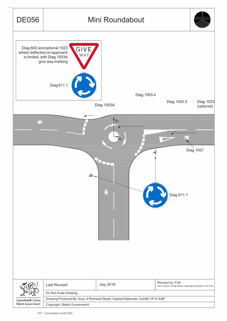
427 Consultation Draft 2020
A4
DE056
Mini Roundabout
Diag 1003A
Diag 1003.4
Diag 1003.3
Diag 1023 (optional)
R1
R2
Diag 1057
Diag 611.1
Last Revised
July 2018
Revised by: PJA Seven House, 18 High Street, Longbridge, Birmingham, B31 2UQ
Do Not Scale Drawing
Drawing Produced By: Arup, 4 Pierhead Street, Capital Waterside, Cardiff, CF10 4QP
Copyright: Welsh Government
Diag 602 and optional 1023
where deflection on approach is limited, with Diag 1003A
give way marking
Diag 611.1
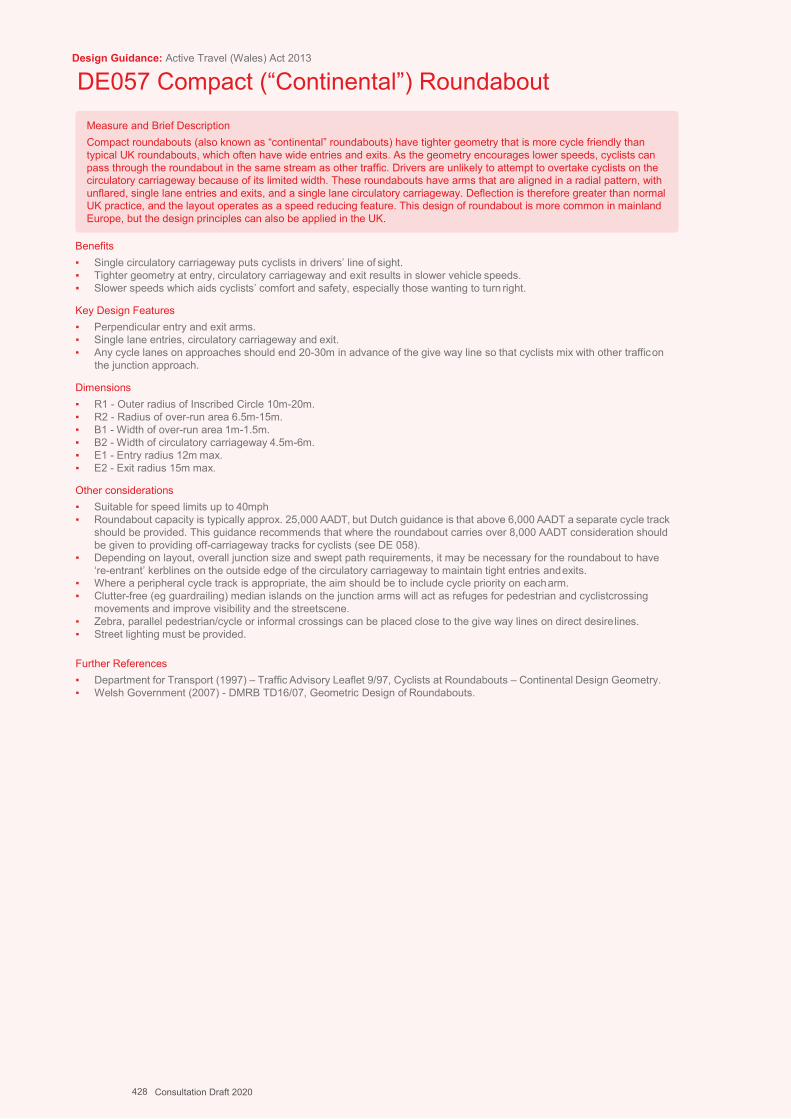
Design Guidance: Active Travel (Wales) Act 2013
DE057 Compact (“Continental”) Roundabout
Benefits ▪ Single circulatory carriageway puts cyclists in drivers’ line of sight. ▪ Tighter geometry at entry, circulatory carriageway and exit results in slower vehicle speeds. ▪ Slower speeds which aids cyclists’ comfort and safety, especially those wanting to turn right.
Key Design Features ▪ Perpendicular entry and exit arms. ▪ Single lane entries, circulatory carriageway and exit. ▪ Any cycle lanes on approaches should end 20-30m in advance of the give way line so that cyclists mix with other traffic on
the junction approach.
Dimensions ▪ R1 - Outer radius of Inscribed Circle 10m-20m. ▪ R2 - Radius of over-run area 6.5m-15m. ▪ B1 - Width of over-run area 1m-1.5m. ▪ B2 - Width of circulatory carriageway 4.5m-6m. ▪ E1 - Entry radius 12m max. ▪ E2 - Exit radius 15m max.
Other considerations ▪ Suitable for speed limits up to 40mph ▪ Roundabout capacity is typically approx. 25,000 AADT, but Dutch guidance is that above 6,000 AADT a separate cycle track
should be provided. This guidance recommends that where the roundabout carries over 8,000 AADT consideration should be given to providing off-carriageway tracks for cyclists (see DE 058).
▪ Depending on layout, overall junction size and swept path requirements, it may be necessary for the roundabout to have ‘re-entrant’ kerblines on the outside edge of the circulatory carriageway to maintain tight entries and exits.
▪ Where a peripheral cycle track is appropriate, the aim should be to include cycle priority on each arm. ▪ Clutter-free (eg guardrailing) median islands on the junction arms will act as refuges for pedestrian and cyclistcrossing
movements and improve visibility and the streetscene. ▪ Zebra, parallel pedestrian/cycle or informal crossings can be placed close to the give way lines on direct desire lines. ▪ Street lighting must be provided.
Further References ▪ Department for Transport (1997) – Traffic Advisory Leaflet 9/97, Cyclists at Roundabouts – Continental Design Geometry. ▪ Welsh Government (2007) - DMRB TD16/07, Geometric Design of Roundabouts.
Measure and Brief Description Compact roundabouts (also known as “continental” roundabouts) have tighter geometry that is more cycle friendly than typical UK roundabouts, which often have wide entries and exits. As the geometry encourages lower speeds, cyclists can pass through the roundabout in the same stream as other traffic. Drivers are unlikely to attempt to overtake cyclists on the circulatory carriageway because of its limited width. These roundabouts have arms that are aligned in a radial pattern, with unflared, single lane entries and exits, and a single lane circulatory carriageway. Deflection is therefore greater than normal UK practice, and the layout operates as a speed reducing feature. This design of roundabout is more common in mainland Europe, but the design principles can also be applied in the UK.
428 Consultation Draft 2020
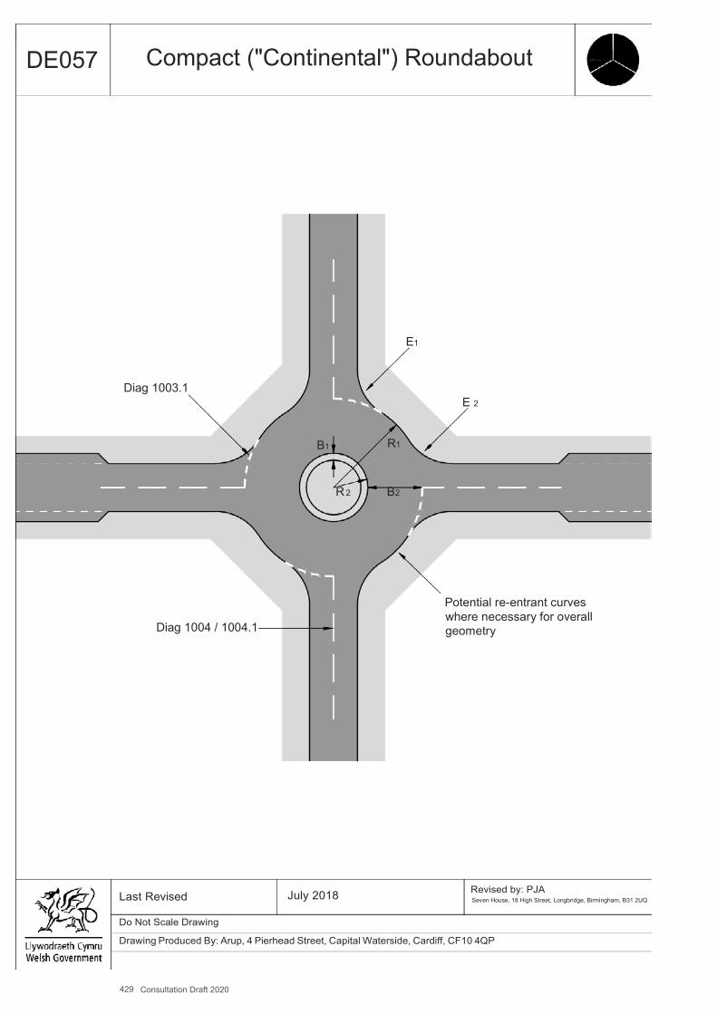
429 Consultation Draft 2020
A4
DE057 Compact ("Continental") Roundabout
E1
Diag 1003.1 E 2
B1 R1
R 2 B2
Diag 1004 / 1004.1
Potential re-entrant curves where necessary for overall geometry
Last Revised July 2018 Revised by: PJA Seven House, 18 High Street, Longbridge, Birmingham, B31 2UQ
Do Not Scale Drawing
Drawing Produced By: Arup, 4 Pierhead Street, Capital Waterside, Cardiff, CF10 4QP
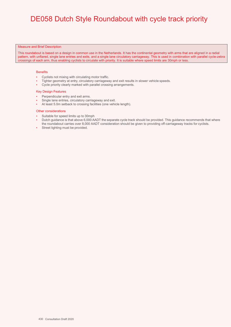
A4
DE058 Dutch Style Roundabout with cycle track priority
Measure and Brief Description
This roundabout is based on a design in common use in the Netherlands. It has the continental geometry with arms that are aligned in a radial pattern, with unflared, single lane entries and exits, and a single lane circulatory carriageway. This is used in combination with parallel cycle-zebra crossings of each arm, thus enabling cyclists to circulate with priority. It is suitable where speed limits are 30mph or less.
Benefits▪ Cyclists not mixing with circulating motor traffic.▪ Tighter geometry at entry, circulatory carriageway and exit results in slower vehicle speeds.▪ Cycle priority clearly marked with parallel crossing arrangements.
Key Design Features▪ Perpendicular entry and exit arms.▪ Single lane entries, circulatory carriageway and exit.▪ At least 5.0m setback to crossing facilities (one vehicle length).
Other considerations▪ Suitable for speed limits up to 30mph▪ Dutch guidance is that above 6,000 AADT the separate cycle track should be provided. This guidance recommends that where
the roundabout carries over 8,000 AADT consideration should be given to providing off-carriageway tracks for cyclists.▪ Street lighting must be provided.
430 Consultation Draft 2020
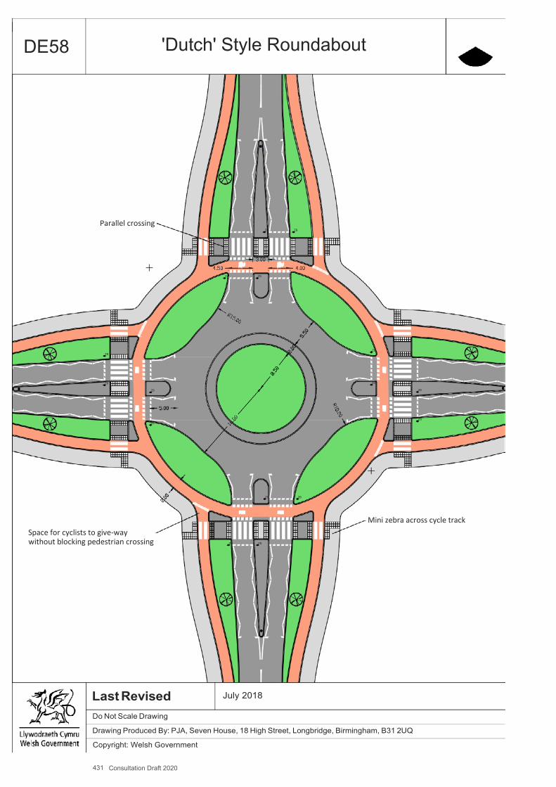
431 Consultation Draft 2020
A4
DE58 'Dutch' Style Roundabout
Parallel crossing ZB ZB
ZB ZB
ZB ZB
ZB ZB
ZB ZB
ZB ZB
ZB ZB
Space for cyclists to give-way without blocking pedestrian crossing ZB ZB
Mini zebra across cycle track
Last Revised Do Not Scale Drawing
July 2018
Drawing Produced By: PJA, Seven House, 18 High Street, Longbridge, Birmingham, B31 2UQ
Copyright: Welsh Government
432 Consultation Draft 2020
Appendix H
Active Travel Walking Routes
Active Travel guidance: appendix H

433 Consultation Draft 2020
Appendix I
Cycling Route Audit Tool
Active Travel guidance: appendix I
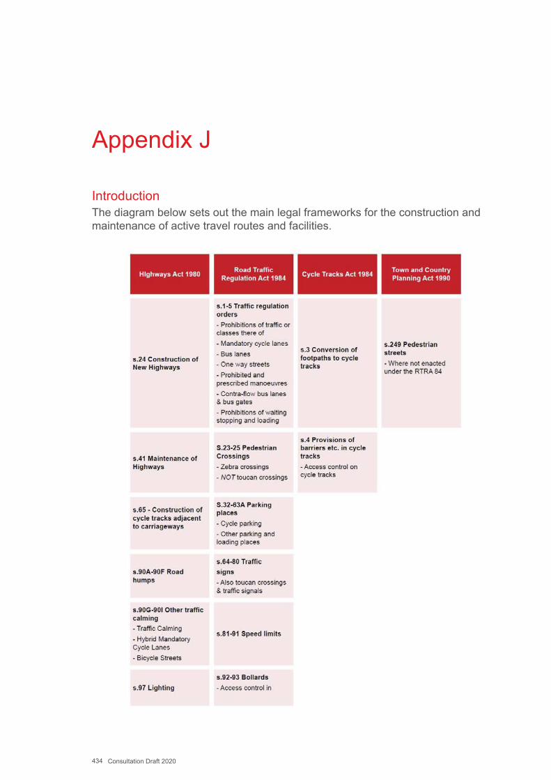
434 Consultation Draft 2020
Appendix J
IntroductionThe diagram below sets out the main legal frameworks for the construction and maintenance of active travel routes and facilities.
435 Consultation Draft 2020
Highways Act 1980Section 62 – General Improvements: The provisions of this Part of this Act empower or require highway authorities and other persons to improve highways. Any such authority may carry out, in relation to a highway maintainable at the public expense by them, any work (including the provision of equipment) for the improvement of the highway.
Section 62 covers any of the following descriptions:
▪ the division of carriageways, provision of roundabouts and variation of therelative widths of carriageways and footways;
▪ the construction of cycle tracks;▪ the provision of subways, refuges, pillars, walls, barriers, rails, fences or
posts for the use or protection of persons using a highway;▪ the construction and reconstruction of bridges and alteration of level of
highways;▪ the planting of trees, shrubs and other vegetation and laying out of grass
verges;▪ the provision, maintenance, alteration, improvement or other dealing with
cattle-grids, by-passes, gates and other works for use in connection withcattle-grids;
▪ the construction, maintenance and removal of road humps;▪ the construction and removal of such traffic calming works as may be
specially authorised by the Secretary of State under section 90G below orprescribed by regulations made by him under section 90H below;
▪ the execution of works for the purpose of draining a highway or ofotherwise preventing surface water from flowing on to it;
▪ the provision of barriers or other works for the purpose of affording to ahighway protection against hazards of nature.
▪ A highway authority may alter or remove any works executed by themunder this section.
Section 65 - Construction of cycle tracks adjacent to carriageways: Empowers highway authorities to provide cycle tracks within or next to highways including a carriageway (i.e. a street). This is not suitable for footpaths (i.e. where the only right of way across the entire width of the highway is by foot). There are no statutory requirements regarding the exercise of this power, although there needs to be evidence that the Highway Authority has exercised this power, particularly given such schemes may be contentious. The erection of the appropriate traffic signing will perform this role to an extent, though it is recommended that any
436 Consultation Draft 2020
conversion is formally made by a resolution of the relevant council committee, following consultation and engagement with stakeholders.
Where a cycle track is proposed adjacent to a highway, but outside its adopted limits, this can be achieved by constructing a cycle track under section 65(1) of the Highways Act as a permitted development under Part 13 of Schedule 2 of the Town and Country Planning (General Permitted Development) Order 1995 (HMSO, 1995).
Sections 90A-90F (Road humps) allows Highway Authorities to construct road humps. Their design and installation is regulated by the Highways (Road Humps) Regulations 1999 (HMSO, 1999b). Advice relating to good practice and legal requirements with respect to de-sign can be found in Section 4 of LTN 1/07 Traffic Calming (Department for Transport, 2007a).
Section 90C (1) of the Highways Act 1980 requires that the Chief Officer of Police is consulted before road humps are installed. Sections 90C (2)&(5) of the same Act require authorities carry out the following procedure before installing road humps:
▪ Notices should be placed in local press and on-street, detailing eachindividual road hump proposed and inviting objections before a stateddeadline not less than 21 days after the publication of proposals
▪ Any objections received should be considered by the Highway Authority.Typically objections will be considered by the relevant committee of theCouncil
Regulation 3 of the Highways (Road Humps) Regulations 1999 requires that the following bodies are consulted in addition to those above:
▪ The Chief Officer of the fire brigade▪ The Chief Officer of any body providing ambulance services▪ Any organisations appearing to the authority to represent persons who
use the highway to which the proposal relates, or to represent personswho are otherwise likely to be affected by the road hump
437 Consultation Draft 2020
Section 90G-90I (Other traffic calming) allows highway authorities to construct other traffic calming measures. These measures are regulated by the Highways (Traffic Calming) Regulations 1999 (HMSO, 1999a), which permit the following measures:
▪ Build-outs▪ Chicanes▪ Gateways▪ Islands▪ Over-run areas▪ Pinch points▪ Rumble devices▪ Combinations of the above
The regulations impose limits on the design of over-run areas and rumble devices. Section 5 of LTN 1/07 Traffic Calming (Department for Transport, 2007a) offers design advice – additional care should be taken to ensure such features do not pose a hazard to cyclists.
Section 97 (Lighting) empowers highway authorities to provide lighting on highways, including cycle tracks. There is no prescribed procedure for providing such lighting.
438 Consultation Draft 2020
Appendix K
Traffic Signs 1.1. Description1.1.1 Active travel routes and facilities require appropriate signage and/or
surface markings reflecting, when present, Traffic Regulation Orders and Notices, along with information signs, warning signs and direction signage. Signs and markings in the highway must comply with the latest edition of the Traffic Signs Regulations and General Directions (TSRGD). There is more freedom to devise locally distinctive signing on routes away from the highway although often highway signs are used for consistency and ease of maintenance. The following signs are the most commonly used for active travel routes. Signs should always be used sparingly to minimise maintenance costs and street clutter.
1.2. Design Requirements▪ Signing should always be kept to the minimum to reduce street clutter
and maintenance costs.▪ The size of a sign and x heights should be appropriate to cyclists and/or
drivers needs depending on the purpose of the sign.▪ Sign poles and lighting columns should never be placed in the centre of
a cycle track or footway (other than signs mounted on bollards). Ideallyposts should be 0.5m clear of the useable surface but if this cannot beachieved, placed at the back of the cycle track or footway.
1.3. Mandatory & Information Signing1.3.1 The respective diagram numbers refer to those specified in the Traffic
Signs Regulations and General Directions (TSRGD), 2016. Designers should refer to the latest edition. Careful positioning of signs associated with cycle facilities is required to comply with siting requirements, to maximise visibility and minimise street clutter. Size and illumination requirements for Diags 955, 956 and 957 were relaxed in 2013 to reduce street clutter.
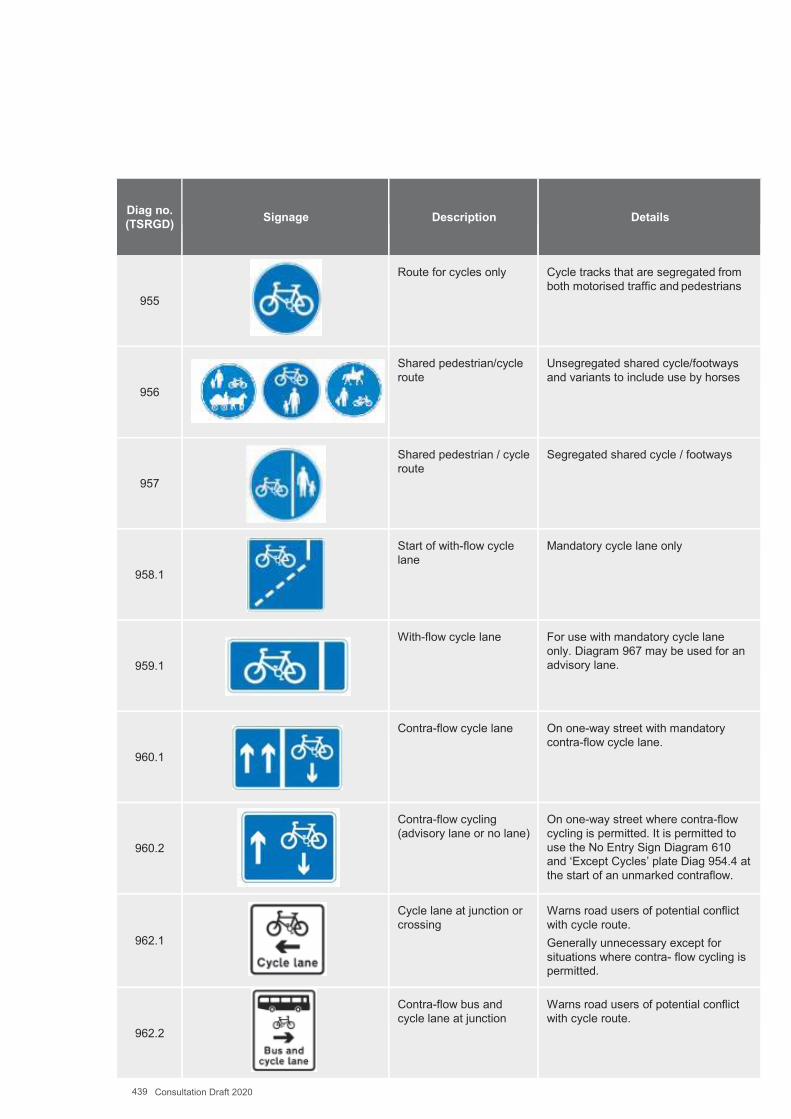
439 Consultation Draft 2020
Diag no. (TSRGD) Signage Description Details
955
Route for cycles only Cycle tracks that are segregated from both motorised traffic and pedestrians
956
Shared pedestrian/cycle route
Unsegregated shared cycle/footways and variants to include use by horses
957
Shared pedestrian / cycle route
Segregated shared cycle / footways
958.1
Start of with-flow cycle lane
Mandatory cycle lane only
959.1
With-flow cycle lane For use with mandatory cycle lane only. Diagram 967 may be used for an advisory lane.
960.1
Contra-flow cycle lane On one-way street with mandatory contra-flow cycle lane.
960.2
Contra-flow cycling (advisory lane or no lane)
On one-way street where contra-flow cycling is permitted. It is permitted to use the No Entry Sign Diagram 610 and ‘Except Cycles’ plate Diag 954.4 at the start of an unmarked contraflow.
962.1
Cycle lane at junction or crossing
Warns road users of potential conflict with cycle route. Generally unnecessary except for situations where contra- flow cycling is permitted.
962.2
Contra-flow bus and cycle lane at junction
Warns road users of potential conflict with cycle route.
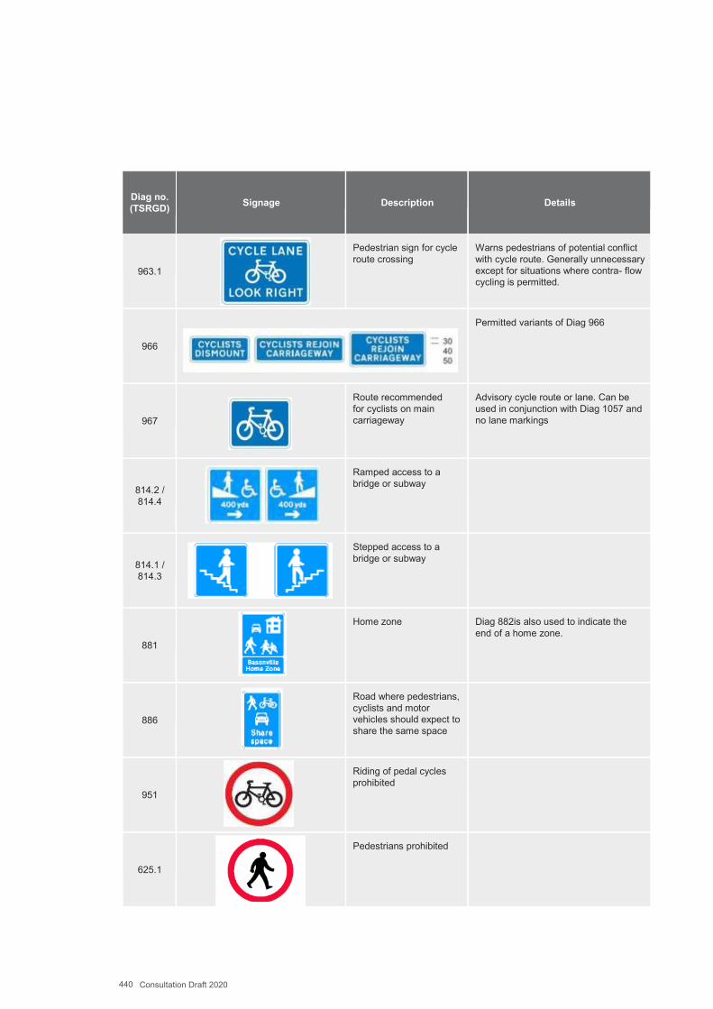
440 Consultation Draft 2020
Diag no. (TSRGD) Signage Description Details
963.1
Pedestrian sign for cycle route crossing
Warns pedestrians of potential conflict with cycle route. Generally unnecessary except for situations where contra- flow cycling is permitted.
966
Permitted variants of Diag 966
967
Route recommended for cyclists on main carriageway
Advisory cycle route or lane. Can be used in conjunction with Diag 1057 and no lane markings
814.2 / 814.4
Ramped access to a bridge or subway
814.1 / 814.3
Stepped access to a bridge or subway
881
Home zone Diag 882is also used to indicate the end of a home zone.
886
Road where pedestrians, cyclists and motor vehicles should expect to share the same space
951
Riding of pedal cycles prohibited
625.1
Pedestrians prohibited
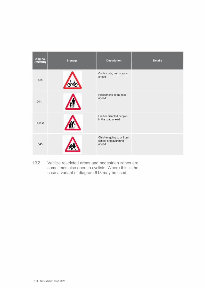
441 Consultation Draft 2020
Diag no. (TSRGD) Signage Description Details
950
Cycle route, test or race ahead
544.1
Pedestrians in the road ahead
544.2
Frail or disabled people in the road ahead
545
Children going to or from school or playground ahead
1.3.2 Vehicle restricted areas and pedestrian zones are sometimes also open to cyclists. Where this is the case a variant of diagram 618 may be used.
618.3c
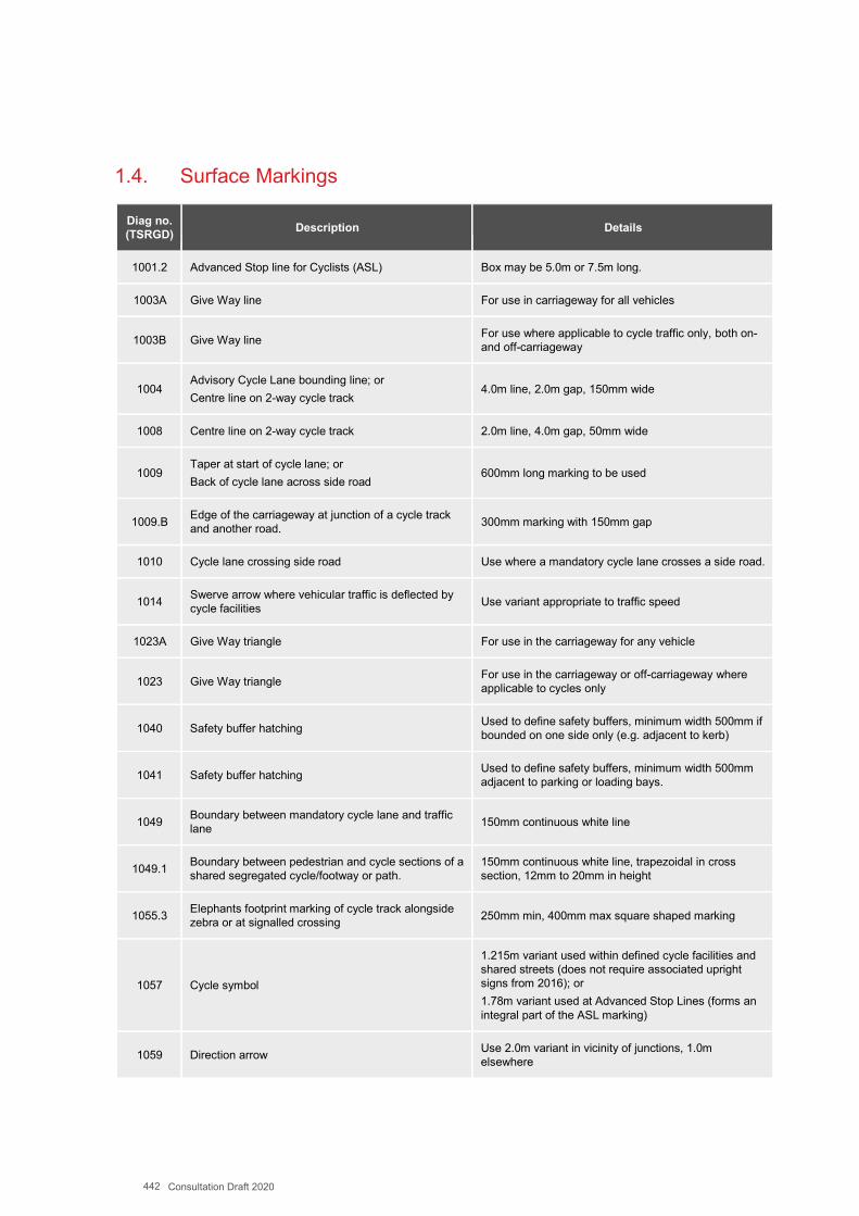
442 Consultation Draft 2020
1.4. Surface Markings
Diag no. (TSRGD) Description Details
1001.2 Advanced Stop line for Cyclists (ASL) Box may be 5.0m or 7.5m long.
1003A Give Way line For use in carriageway for all vehicles
1003B Give Way line For use where applicable to cycle traffic only, both on- and off-carriageway
1004 Advisory Cycle Lane bounding line; or Centre line on 2-way cycle track
4.0m line, 2.0m gap, 150mm wide
1008 Centre line on 2-way cycle track 2.0m line, 4.0m gap, 50mm wide
1009 Taper at start of cycle lane; or Back of cycle lane across side road
600mm long marking to be used
1009.B Edge of the carriageway at junction of a cycle track and another road. 300mm marking with 150mm gap
1010 Cycle lane crossing side road Use where a mandatory cycle lane crosses a side road.
1014 Swerve arrow where vehicular traffic is deflected by cycle facilities Use variant appropriate to traffic speed
1023A Give Way triangle For use in the carriageway for any vehicle
1023 Give Way triangle For use in the carriageway or off-carriageway where applicable to cycles only
1040 Safety buffer hatching Used to define safety buffers, minimum width 500mm if bounded on one side only (e.g. adjacent to kerb)
1041 Safety buffer hatching Used to define safety buffers, minimum width 500mm adjacent to parking or loading bays.
1049 Boundary between mandatory cycle lane and traffic lane 150mm continuous white line
1049.1 Boundary between pedestrian and cycle sections of a shared segregated cycle/footway or path.
150mm continuous white line, trapezoidal in cross section, 12mm to 20mm in height
1055.3 Elephants footprint marking of cycle track alongside zebra or at signalled crossing 250mm min, 400mm max square shaped marking
1057 Cycle symbol
1.215m variant used within defined cycle facilities and shared streets (does not require associated upright signs from 2016); or 1.78m variant used at Advanced Stop Lines (forms an integral part of the ASL marking)
1059 Direction arrow Use 2.0m variant in vicinity of junctions, 1.0m elsewhere
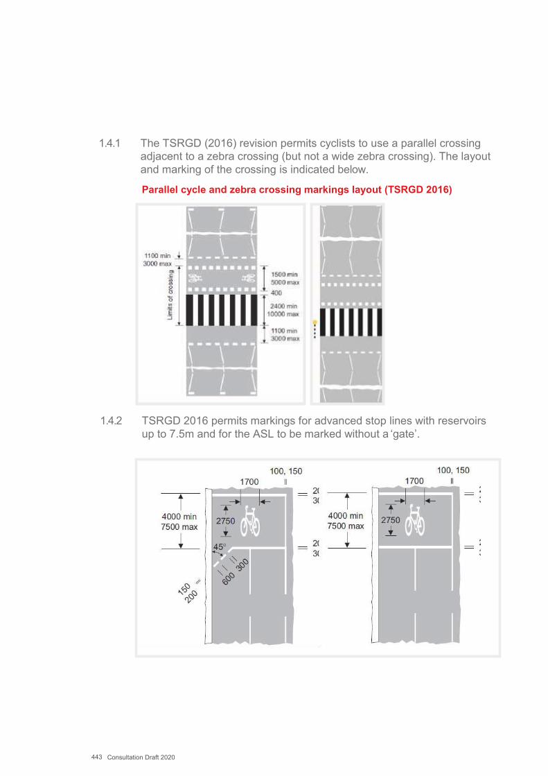
443 Consultation Draft 2020
1.4.1 The TSRGD (2016) revision permits cyclists to use a parallel crossing adjacent to a zebra crossing (but not a wide zebra crossing). The layout and marking of the crossing is indicated below.
Parallel cycle and zebra crossing markings layout (TSRGD 2016)
1.4.2 TSRGD 2016 permits markings for advanced stop lines with reservoirs up to 7.5m and for the ASL to be marked without a ‘gate’.
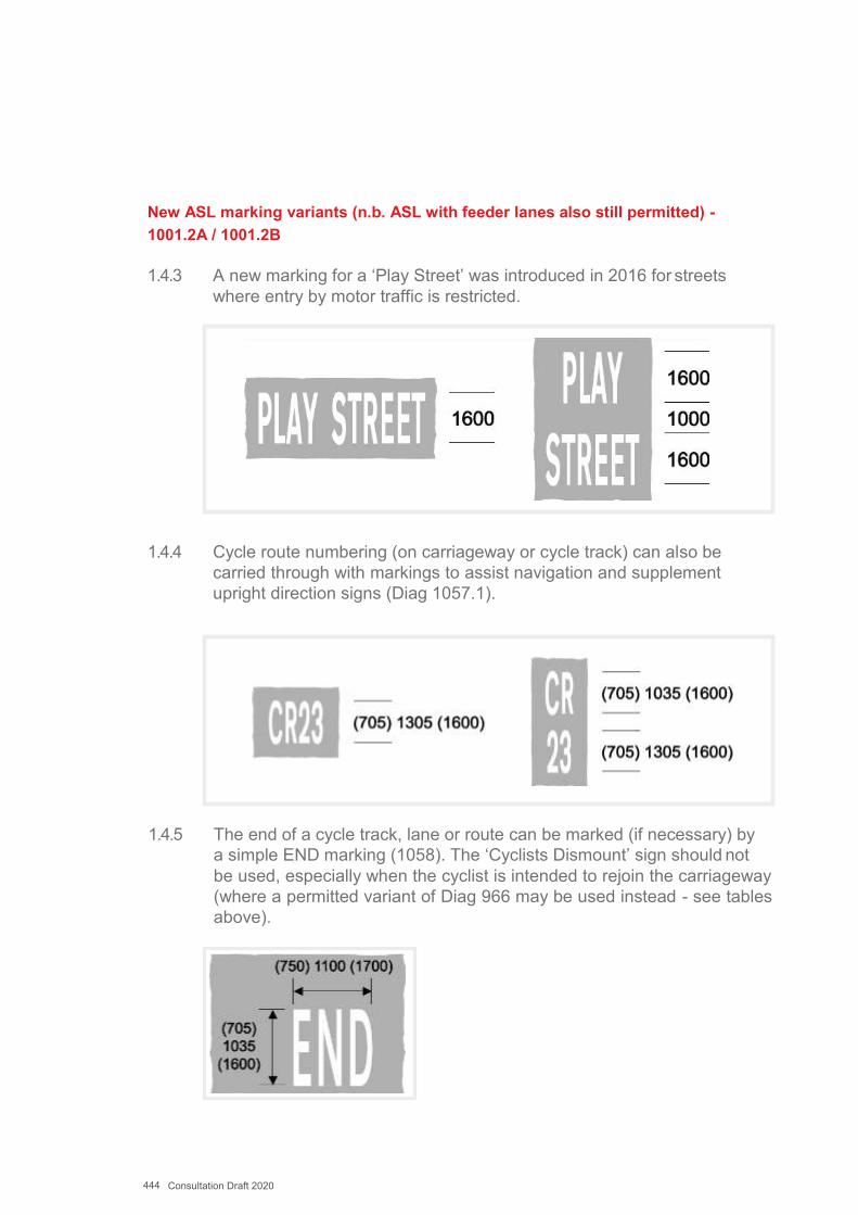
444 Consultation Draft 2020
New ASL marking variants (n.b. ASL with feeder lanes also still permitted) - 1001.2A / 1001.2B
1.4.3 A new marking for a ‘Play Street’ was introduced in 2016 for streets where entry by motor traffic is restricted.
1.4.4 Cycle route numbering (on carriageway or cycle track) can also be carried through with markings to assist navigation and supplement upright direction signs (Diag 1057.1).
1.4.5 The end of a cycle track, lane or route can be marked (if necessary) by a simple END marking (1058). The ‘Cyclists Dismount’ sign should not be used, especially when the cyclist is intended to rejoin the carriageway (where a permitted variant of Diag 966 may be used instead - see tables above).
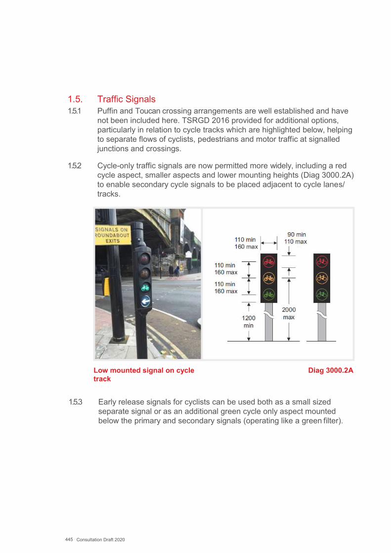
445 Consultation Draft 2020
1.5. Traffic Signals 1.5.1 Puffin and Toucan crossing arrangements are well established and have
not been included here. TSRGD 2016 provided for additional options, particularly in relation to cycle tracks which are highlighted below, helping to separate flows of cyclists, pedestrians and motor traffic at signalled junctions and crossings.
1.5.2 Cycle-only traffic signals are now permitted more widely, including a red cycle aspect, smaller aspects and lower mounting heights (Diag 3000.2A) to enable secondary cycle signals to be placed adjacent to cycle lanes/ tracks.
Low mounted signal on cycle track
Diag 3000.2A
1.5.3 Early release signals for cyclists can be used both as a small sized separate signal or as an additional green cycle only aspect mounted below the primary and secondary signals (operating like a green filter).
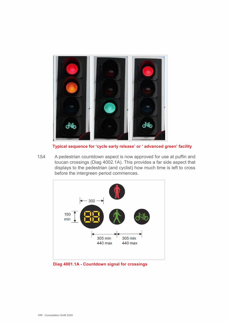
446 Consultation Draft 2020
Typical sequence for ‘cycle early release’ or ‘ advanced green’ facility
1.5.4 A pedestrian countdown aspect is now approved for use at puffin and toucan crossings (Diag 4002.1A). This provides a far side aspect that displays to the pedestrian (and cyclist) how much time is left to cross before the intergreen period commences.
Diag 4001.1A - Countdown signal for crossings
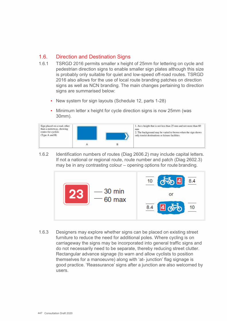
447 Consultation Draft 2020
1.6. Direction and Destination Signs 1.6.1 TSRGD 2016 permits smaller x height of 25mm for lettering on cycle and
pedestrian direction signs to enable smaller sign plates although this size is probably only suitable for quiet and low-speed off-road routes. TSRGD 2016 also allows for the use of local route branding patches on direction signs as well as NCN branding. The main changes pertaining to direction signs are summarised below:
▪ New system for sign layouts (Schedule 12, parts 1-28)
▪ Minimum letter x height for cycle direction signs is now 25mm (was30mm).
1.6.2 Identification numbers of routes (Diag 2606.2) may include capital letters. If not a national or regional route, route number and patch (Diag 2602.3) may be in any contrasting colour – opening options for route branding.
1.6.3 Designers may explore whether signs can be placed on existing street furniture to reduce the need for additional poles. Where cycling is on carriageway the signs may be incorporated into general traffic signs and do not necessarily need to be separate, thereby reducing street clutter. Rectangular advance signage (to warn and allow cyclists to position themselves for a manoeuvre) along with ‘at- junction’ flag signage is good practice. ‘Reassurance’ signs after a junction are also welcomed by users.
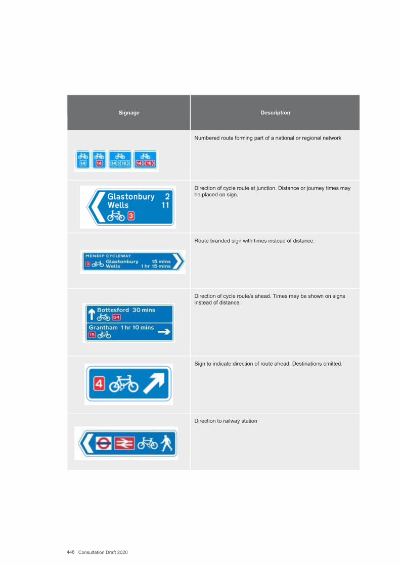
448 Consultation Draft 2020
Signage Description
Numbered route forming part of a national or regional network
Direction of cycle route at junction. Distance or journey times may be placed on sign.
Route branded sign with times instead of distance.
Direction of cycle route/s ahead. Times may be shown on signs instead of distance.
Sign to indicate direction of route ahead. Destinations omitted.
Direction to railway station
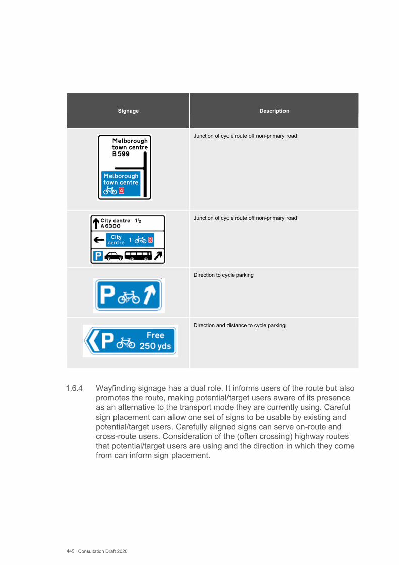
449 Consultation Draft 2020
Signage Description
Junction of cycle route off non-primary road
Junction of cycle route off non-primary road
Direction to cycle parking
Direction and distance to cycle parking
1.6.4 Wayfinding signage has a dual role. It informs users of the route but also promotes the route, making potential/target users aware of its presence as an alternative to the transport mode they are currently using. Careful sign placement can allow one set of signs to be usable by existing and potential/target users. Carefully aligned signs can serve on-route and cross-route users. Consideration of the (often crossing) highway routes that potential/target users are using and the direction in which they come from can inform sign placement.
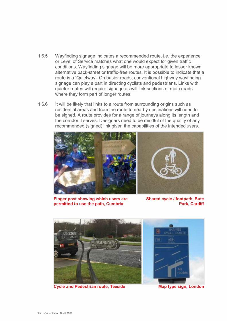
450 Consultation Draft 2020
1.6.5 Wayfinding signage indicates a recommended route, i.e. the experience or Level of Service matches what one would expect for given traffic conditions. Wayfinding signage will be more appropriate to lesser known alternative back-street or traffic-free routes. It is possible to indicate that a route is a ‘Quietway’. On busier roads, conventional highway wayfinding signage can play a part in directing cyclists and pedestrians. Links with quieter routes will require signage as will link sections of main roads where they form part of longer routes.
1.6.6 It will be likely that links to a route from surrounding origins such as residential areas and from the route to nearby destinations will need to be signed. A route provides for a range of journeys along its length and the corridor it serves. Designers need to be mindful of the quality of any recommended (signed) link given the capabilities of the intended users.
Finger post showing which users are permitted to use the path, Cumbria
Shared cycle / footpath, Bute Park, Cardiff
Cycle and Pedestrian route, Teeside Map type sign, London
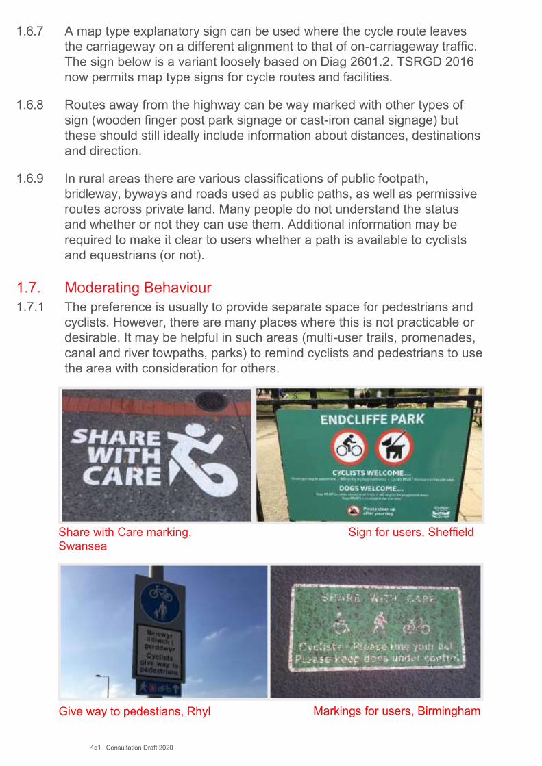
451 Consultation Draft 2020
1.6.7 A map type explanatory sign can be used where the cycle route leaves the carriageway on a different alignment to that of on-carriageway traffic. The sign below is a variant loosely based on Diag 2601.2. TSRGD 2016 now permits map type signs for cycle routes and facilities.
1.6.8 Routes away from the highway can be way marked with other types of sign (wooden finger post park signage or cast-iron canal signage) but these should still ideally include information about distances, destinations and direction.
1.6.9 In rural areas there are various classifications of public footpath, bridleway, byways and roads used as public paths, as well as permissive routes across private land. Many people do not understand the status and whether or not they can use them. Additional information may be required to make it clear to users whether a path is available to cyclists and equestrians (or not).
1.7. Moderating Behaviour1.7.1 The preference is usually to provide separate space for pedestrians and
cyclists. However, there are many places where this is not practicable or desirable. It may be helpful in such areas (multi-user trails, promenades, canal and river towpaths, parks) to remind cyclists and pedestrians to use the area with consideration for others.
Share with Care marking, Swansea
Sign for users, Sheffield
Give way to pedestians, Rhyl Markings for users, Birmingham
452 Consultation Draft 2020
Appendix L
Network Planning Background InformationIntegration with Infrastructure Planning and Delivery Programmes
Successful integration with other policies, plans and programmes will deliver better active travel schemes more quickly. These plans might include:
Transport and Land Use Plans;▪ existing walking, cycling or active travel plans▪ plans or proposals for the development of non-vehicular routes, quiet▪ lanes, home zones or traffic calming▪ strategic bus plans or schemes▪ rights of way improvement plans▪ traffic management plans▪ city centre management plans▪ any Network Rail plans such as new stations, station improvements
or changes to bridges or level crossings as part of the proposedelectrification of the lines
Road safety strategies and schemes▪ safe routes in communities schemes▪ plans and strategies by third parties that include infrastructure provision
for active travel▪ Local Development Plans (including Supplementary Planning Guidance
and Masterplans)▪ Local transport plans▪ Wales Transport Strategy▪ National transport plans▪ Highway maintenance plans▪ Any plans for new highways (e.g. linking to new development sites)

453 Consultation Draft 2020
Other Plans▪ schools▪ tourism▪ countryside▪ public rights of way▪ highway maintenance▪ access officers▪ rehabilitation officers
Integration with Policy and Promotion MeasuresThe plans also need to be integrated within a wider programme of measures to improve facilities for active travel. The following non- infrastructure measures should be considered in conjunction with any walking and cycling improvement schemes.
▪ Ensure that planning policy guides new development towards sustainablelocations that maximise the potential for walking and cycling trips.
▪ ensure that transport policy and highway development control processesresult in new development site layouts that are designed to maximiseaccess on foot and cycle.
▪ ensure that the needs of pedestrians and cyclists are considered whenimplementing any changes to highway infrastructure.
▪ encourage travel plans, which provide a strategy and action plan forfacilitating and encouraging travel by sustainable modes, from allsignificant developments through the planning process.
▪ explore the potential for new larger-scale developments to fund walkingand cycling audits within adjacent neighbourhoods, potentially securedthrough section 106 agreements.
▪ promotion of active travel through measures such as:▪ production and dissemination of public walking and cycling maps, which
should also provide information on public transport;▪ organised activities for specific user groups, such as ‘walk/bike to▪ school month’; and;▪ dissemination of publicity regarding the potential health and financial
benefits of regular active travel.▪ work with partners in the health sector to develop walking and cycling-
based initiatives to help meet shared objectives for active travel.
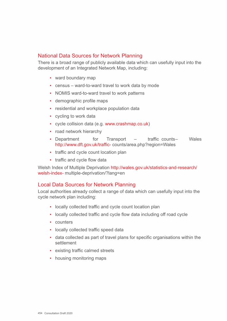
454 Consultation Draft 2020
National Data Sources for Network PlanningThere is a broad range of publicly available data which can usefully input into the development of an Integrated Network Map, including:
▪ ward boundary map▪ census – ward-to-ward travel to work data by mode▪ NOMIS ward-to-ward travel to work patterns▪ demographic profile maps▪ residential and workplace population data▪ cycling to work data▪ cycle collision data (e.g. www.crashmap.co.uk)▪ road network hierarchy▪ Department for Transport – traffic counts – Wales
http://www.dft.gov.uk/traffic- counts/area.php?region=Wales▪ traffic and cycle count location plan▪ traffic and cycle flow data
Welsh Index of Multiple Deprivation http://wales.gov.uk/statistics-and-research/welsh-index- multiple-deprivation/?lang=en
Local Data Sources for Network PlanningLocal authorities already collect a range of data which can usefully input into the cycle network plan including:
▪ locally collected traffic and cycle count location plan▪ locally collected traffic and cycle flow data including off road cycle▪ counters▪ locally collected traffic speed data▪ data collected as part of travel plans for specific organisations within the
settlement▪ existing traffic calmed streets▪ housing monitoring maps

455 Consultation Draft 2020
Origin / Destinations to be mapped in the Active Travel ActFor the Active Travel Act the following departure and destination points need to be mapped as part of the production of the existing routes map.
▪ main office locations and business parks▪ public transport nodes▪ libraries▪ post offices▪ sports stadia▪ leisure centres▪ parks▪ religious buildings▪ hospitals▪ shopping centres▪ educational establishments▪ cultural institutions▪ tourist advice centres▪ tourist and leisure attractions▪ recreational walking and cycling routes▪ cycle maintenance and repair shops
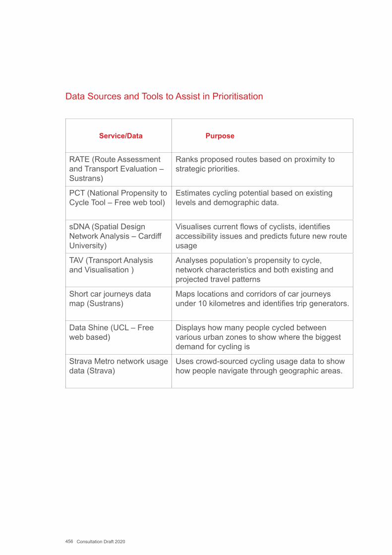
456 Consultation Draft 2020
Data Sources and Tools to Assist in Prioritisation
Service/Data Purpose
RATE (Route Assessment and Transport Evaluation – Sustrans)
Ranks proposed routes based on proximity to strategic priorities.
PCT (National Propensity to Cycle Tool – Free web tool)
Estimates cycling potential based on existing levels and demographic data.
sDNA (Spatial Design Network Analysis – Cardiff University)
Visualises current flows of cyclists, identifies accessibility issues and predicts future new route usage
TAV (Transport Analysis and Visualisation )
Analyses population’s propensity to cycle, network characteristics and both existing and projected travel patterns
Short car journeys data map (Sustrans)
Maps locations and corridors of car journeys under 10 kilometres and identifies trip generators.
Data Shine (UCL – Free web based)
Displays how many people cycled between various urban zones to show where the biggest demand for cycling is
Strava Metro network usage data (Strava)
Uses crowd-sourced cycling usage data to show how people navigate through geographic areas.
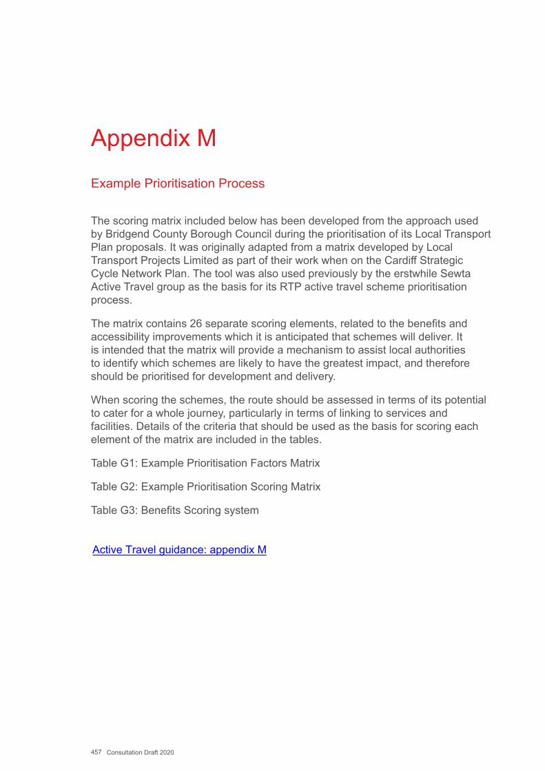
457 Consultation Draft 2020
Appendix M
Example Prioritisation Process
The scoring matrix included below has been developed from the approach used by Bridgend County Borough Council during the prioritisation of its Local Transport Plan proposals. It was originally adapted from a matrix developed by Local Transport Projects Limited as part of their work when on the Cardiff Strategic Cycle Network Plan. The tool was also used previously by the erstwhile Sewta Active Travel group as the basis for its RTP active travel scheme prioritisation process.
The matrix contains 26 separate scoring elements, related to the benefits and accessibility improvements which it is anticipated that schemes will deliver. It is intended that the matrix will provide a mechanism to assist local authorities to identify which schemes are likely to have the greatest impact, and therefore should be prioritised for development and delivery.
When scoring the schemes, the route should be assessed in terms of its potential to cater for a whole journey, particularly in terms of linking to services and facilities. Details of the criteria that should be used as the basis for scoring each element of the matrix are included in the tables.
Table G1: Example Prioritisation Factors Matrix
Table G2: Example Prioritisation Scoring Matrix
Table G3: Benefits Scoring system
Active Travel guidance: appendix M
Related Documents