Control Engineering Practice 7 (1999) 459}468 Active sonar-based bottom-following for unmanned underwater vehicles M. Caccia*, G. Bruzzone, G. Veruggio Consiglio Nazionale delle Ricerche, Istituto Automazione Navale, Via De Marini, 6, 16149 Genova, Italy Received 5 December 1997; accepted 11 August 1998 Abstract The problem of high-precision bottom-following in the proximity of the seabed for open-frame unmanned underwater vehicles (UUVs) is addressed in this paper. The suggested approach consists of the integration of a guidance and control system with an active multi-hypothesis extended Kalman "lter, able to estimate the motion of the vehicle with respect to the bottom pro"le. The guidance module is based on the de"nition of a suitable Lyapunov function associated with the bottom-following task, while the motion controller is a conventional autopilot, performing autoheading, autodepth, and autospeed. The motion of the vehicle is estimated from range and bearing measurements supplied by a high-frequency pencil-beam pro"ling sonar. Moreover, a general-purpose sensor-based guidance and control system for advanced UUVs, able to manage active sensing-based guidance and motion estimation modules, is presented. An application of the proposed architecture to execute high-precision bottom-following using Romeo, a prototype UUV, developed by the Robotics Dept. of the Istituto Automazione Navale, is described. Experimental results of tests, conducted in a high-diving pool with the vehicle equipped with a sonar pro"ler, are presented. ( 1999 Published by Elsevier Science ¸td. All rights reserved. Keywords: Underwater vehicles; Range sensing; Motion estimation; Extended Kalman "lters; Guidance systems; Active sensing 1. Introduction High-precision motion control of unmanned under- water vehicles (UUVs) at low speeds in the proximity of the seabed is required in many operational applications such as visual surveys of the seabed, mosaicking, censuses of marine life or features, and constant-speed dragging of sensors/samplers to obtain regular measurements. The operating vehicle, generally an open-frame UUV equip- ped with a scienti"c payload, is required to be able to follow the sea bottom at short distances (less than 2 m) at a speed of some tenths of centimeters per second (typi- cally lower than 0.5 m/s). The task of bottom-following, i.e., &&maintaining a "xed altitude above an arbitrary surface whose characteristics may or may not be known'' (Bennett et al., 1995), has been extensively treated in the literature in the case of torpedo-like, survey-class autonomous underwater ve- hicles (AUVs). In particular, the case of AUVs equipped *Corresponding author. Tel.: #39 010 6475612; fax: #39 010 6475600; e-mail: max@ian.ge.cnr.it. with one or two downward-looking sonar altimeters, which measure the vehicle's distance from the bottom and enable it to estimate the seabed pro"le, has been investigated in Bennett et al. (1995). Aspects concerning the estimation of the bottom slope in relation to the vehicle, the management of transitions between di!erent slope sections, and the relations between bottom-follow- ing and other tasks, are examined in Santos et al. (1995a, b). In this paper the problem of bottom-following is addressed for a class of open-frame UUVs, moving at low speeds very close to the seabed. In these opera- tional conditions, the use of high-frequency pencil- beam pro"ling sonars (which have a shorter operating range and ensure higher precision than traditional echo- sounders) and recursive "ltering techniques allows high-precision estimates of the UUV motion with respect to the seabed pro"le. Recent experimental results have also demonstrated that estimator perfor- mances can be enhanced by feature-related control of the motion of the pro"ler sonar (Caccia et al., 1997). 0967-0661/99/$ - see front matter ( 1999 Published by Elsevier Science Ltd. All rights reserved. PII: S 0 9 6 7 - 0 6 6 1 ( 9 8 ) 0 0 1 6 8 - 3

Welcome message from author
This document is posted to help you gain knowledge. Please leave a comment to let me know what you think about it! Share it to your friends and learn new things together.
Transcript
Control Engineering Practice 7 (1999) 459}468
Active sonar-based bottom-following for unmannedunderwater vehicles
M. Caccia*, G. Bruzzone, G. Veruggio
Consiglio Nazionale delle Ricerche, Istituto Automazione Navale, Via De Marini, 6, 16149 Genova, Italy
Received 5 December 1997; accepted 11 August 1998
Abstract
The problem of high-precision bottom-following in the proximity of the seabed for open-frame unmanned underwater vehicles(UUVs) is addressed in this paper. The suggested approach consists of the integration of a guidance and control system with an activemulti-hypothesis extended Kalman "lter, able to estimate the motion of the vehicle with respect to the bottom pro"le. The guidancemodule is based on the de"nition of a suitable Lyapunov function associated with the bottom-following task, while the motioncontroller is a conventional autopilot, performing autoheading, autodepth, and autospeed. The motion of the vehicle is estimatedfrom range and bearing measurements supplied by a high-frequency pencil-beam pro"ling sonar. Moreover, a general-purposesensor-based guidance and control system for advanced UUVs, able to manage active sensing-based guidance and motion estimationmodules, is presented. An application of the proposed architecture to execute high-precision bottom-following using Romeo,a prototype UUV, developed by the Robotics Dept. of the Istituto Automazione Navale, is described. Experimental resultsof tests, conducted in a high-diving pool with the vehicle equipped with a sonar pro"ler, are presented. ( 1999 Published by ElsevierScience ¸td. All rights reserved.
Keywords: Underwater vehicles; Range sensing; Motion estimation; Extended Kalman "lters; Guidance systems; Active sensing
1. Introduction
High-precision motion control of unmanned under-water vehicles (UUVs) at low speeds in the proximity ofthe seabed is required in many operational applicationssuch as visual surveys of the seabed, mosaicking, censusesof marine life or features, and constant-speed dragging ofsensors/samplers to obtain regular measurements. Theoperating vehicle, generally an open-frame UUV equip-ped with a scienti"c payload, is required to be able tofollow the sea bottom at short distances (less than 2 m) ata speed of some tenths of centimeters per second (typi-cally lower than 0.5 m/s).
The task of bottom-following, i.e., &&maintaining a "xedaltitude above an arbitrary surface whose characteristicsmay or may not be known'' (Bennett et al., 1995), hasbeen extensively treated in the literature in the case oftorpedo-like, survey-class autonomous underwater ve-hicles (AUVs). In particular, the case of AUVs equipped
*Corresponding author. Tel.: #39 010 6475612; fax: #39 0106475600; e-mail: [email protected].
with one or two downward-looking sonar altimeters,which measure the vehicle's distance from the bottomand enable it to estimate the seabed pro"le, has beeninvestigated in Bennett et al. (1995). Aspects concerningthe estimation of the bottom slope in relation to thevehicle, the management of transitions between di!erentslope sections, and the relations between bottom-follow-ing and other tasks, are examined in Santos et al.(1995a, b).
In this paper the problem of bottom-following isaddressed for a class of open-frame UUVs, movingat low speeds very close to the seabed. In these opera-tional conditions, the use of high-frequency pencil-beam pro"ling sonars (which have a shorter operatingrange and ensure higher precision than traditional echo-sounders) and recursive "ltering techniques allowshigh-precision estimates of the UUV motion with respectto the seabed pro"le. Recent experimental resultshave also demonstrated that estimator perfor-mances can be enhanced by feature-related control ofthe motion of the pro"ler sonar (Caccia et al.,1997).
0967-0661/99/$ - see front matter ( 1999 Published by Elsevier Science Ltd. All rights reserved.PII: S 0 9 6 7 - 0 6 6 1 ( 9 8 ) 0 0 1 6 8 - 3
A general-purpose sensor-based guidance and controlsystem for advanced UUVs, able to manage the activesensing-based guidance and estimation techniques men-tioned above, has been designed. The architecture con-sists of conventional UUV autopilot and navigationsystems, integrated with motion-task-oriented guidance,an environment-based motion estimator and externalsensor controller modules, as discussed in Section 2,where the distinction between a task-independent lowerlevel (autopilot and external sensor controller) anda task-based upper level, consisting of guidance andactive estimation modules, is emphasized.
The bottom-following task is de"ned in Section 3.A guidance algorithm, based on the de"nition ofa Lyapunov function of the error in the distance from theseabed and the choice of autopilot set-points to make itnegative de"nite, is presented.
The bottom-estimation technique is discussed inSection 4. The bottom pro"le and its distance from thevehicle are estimated by an active multi-hypothesis ex-tended Kalman "lter, which processes the pro"ler sonarrange and bearing measurements.
The proposed sensor-based guidance and control sys-tem has been implemented on Romeo, a prototype UUVdeveloped by C.N.R.-I.A.N. for marine science applica-tions and robotics research (Veruggio et al., 1996), andtested in a pool.
Section 5 describes the hardware and software archi-tecture of Romeo, while experimental tests and resultsare presented in Section 6.
2. Sensor-based guidance and control system
A general-purpose sensor-based guidance and controlsystem for UUVs is described below. Attention is focusedon the guidance of the vehicle in respect to its operationalenvironment. In this way, &&external sensors'', whichmeasure interactions between the robot and the environ-ment in preferred directions (Samson et al., 1991), areconsidered. Here the aspects of this architecture con-cerned with the execution of the task of bottom-followingare presented, while an application to the horizontalmotion guidance and control of a prototype UUV isdescribed in Caccia et al. (1998). Since the unpredictabil-ity of subsea environments and the limitations of thestate-of-the-art machine-intelligence techniques makesreal-world operations reliable only in the presence ofpossible human intervention (Sayers et al., 1996), a basicrequirement in developing guidance and control systemsfor operational UUVs is to enable the human operator totele-operate the robot, by interacting with each level ofthe control architecture (Sheridan, 1989). In this way,a modular guidance and control system has been de-signed, integrating conventional autopilot and navi-gation modules with an &&external sensors'' controller, an
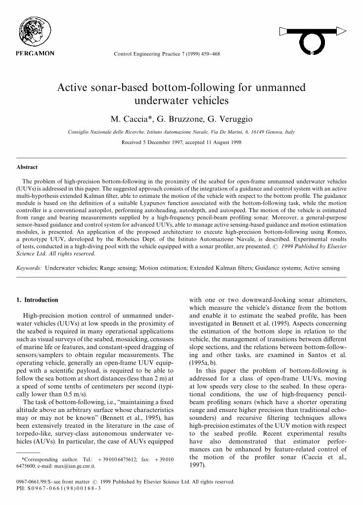
Fig. 1. Bottom-following architecture for UUVs.
active estimator of the motion in respect to the opera-tional environment, and guidance modules. The resultingsystem architecture is depicted in Fig. 1, where sub-modules and data #ow required to execute the bottom-following task are pointed out.
The UUV autopilot controls the vehicle's heading, atti-tude (pitch and roll), depth, and horizontal speed (surgeand sway). As discussed in Fossen (1994), in mostpractical applications, autopilots constituted by simpleuncoupled controllers of PID-type are su$cient. In par-ticular, typical survey applications can be executed byvehicles performing automatic control of heading (PID-type), depth (PID-type) and surge (PI-type). The auto-pilot is organized in four layers. The "rst layer is theautomatic control mode, which generates the forces andtorques to be applied to the vehicle to obtain the desiredbehavior. In the second layer, the thrust mapping func-tion maps the required forces and torque in the vector ofthrust to be applied to the actuators, according to thevehicle's thruster con"guration and user-de"ned require-ments such as low-power consumption or motion pre-cision. In the third layer the voltage mapping functionmaps the thrust vector containing the desired motorthrusts into a voltage vector to be sent to the boards ofthe servo-motor drivers. Finally, in the lowest mode, eachthruster voltage can be set directly.
The vehicle motion is estimated by the navigationsystem. Data supplied by a compass, a gyro, inclino-meters, a depth-meter, a current-meter and/or a Dopplervelocimeter, are integrated to estimate the vehicle kin-ematics state required by the Autopilot. In addition, theintegration of acoustic positioning systems and/or linear
460 M. Caccia et al./Control Engineering Practice 7 (1999) 459}468
accelerometer measurements can allow the vehicle'sabsolute position to be estimated.
The autopilot and navigation systems are independentof the task the robot has to accomplish and are su$cientto enable the human pilot, helped by video feedback froma TV camera mounted on the vehicle, to tele-operate thevehicle. This is the case in many operational ROVs.
The guidance system generates autopilot set-points toperform motion tasks of di!erent types. Since in theoperational area, the vehicle moves in the proximity ofenvironmental features such as the seabed or man-madestructures, a number of operational motion tasks can bede"ned in respect to the interactions between the vehicleand its surroundings. These motion functions can beclassi"ed into safety tasks such as obstacle, bottom andsurface avoidance, and environment-based tasks as bot-tom-following, ice-canopy following, and wall-followingwith a pre-de"ned orientation. Moreover, the vehicle canbe required to move in an earth-"xed reference frame tooperate in a well-de"ned area. In this case, free-spacemotion tasks are executed, such as reaching a targetframe (position and orientation) and remaining station-ary on site, even in the presence of disturbances (Cacciaet al., 1998).
Underwater optic and acoustic visual sensors canprovide feedback on the interactions between the UUVand the operational environment. Since it is possible tofocus the attention of pro"ling sonars and pan-tilt TV-cameras in particular directions, the most advancedUUVs provide an external sensor controller, able to ac-quire data and to control the motion of these devicesboth in the environment and in the vehicle "xed referenceframe.
In particular, high-frequency pencil-beam pro"lersonars can provide high-precision measurements ofthe interactions between the vehicle and the environmentat short ranges. In this case, the sonar controller pilotsthe pro"ler sonar head motion in order to satisfy thehuman operator and/or the requirements of the data-processing algorithm. The sonar pro"ler motion anddata acquisition can be controlled at various levels. Con-tinuous pings in a "xed direction, and clockwise andcounterclockwise radar-like circular scans and sweeps ina circular sector are described in a vehicle/sensor-"xedreference frame. Sweeps between the absolute horizontalor vertical directions have to be described in an earth-"xed reference frame, and need vehicle heading or pitchdata to be acquired. These di!erent pro"ler motionmodes correspond to di!erent layers of the Sonar Con-troller.
The motion of the vehicle in respect to basic featuresdetected in the operational environment is estimatedby the environment-based motion estimator. Where it ispossible to control the sensor attention, the estimatorperformances are increased by adopting task-driven andfeature-related active sensing techniques. Task-driven
control of visual attention can be performed indepen-dently of the estimation processing (Swayn and Stricker,1993). For instance, when the task of obstacle detection isperformed, a pro"ling sonar looks ahead, sweepingacross a sector in the vehicle "xed reference frame. Fea-ture-related control of visual attention allows the es-timator performance to be improved, controlling thesensor movements on the basis of the result of the estima-tion processing. In the case of bottom-following, a moreprecise tracking of the desired distance from the seabed inthe presence of sudden changes in the bottom pro"le isallowed by the availability of a high-precision estimatorof the bottom slope and the vehicle's distance from theseabed. A feature-related control of the pro"ler sonar isperformed to increase the precision in the slope estimatetracking the linear surface, which currently approximatesthe seabed pro"le. In particular, the bottom pro"le istracked by the pro"ler sonar, sweeping a circular sectorwith extremes b(1) and b(2) (see Fig. 1), determined by thebottom estimator.
A more detailed description of the bottom-followingand bottom-estimation modules is given in the next twosections.
3. Bottom-following: task de5nition and guidance module
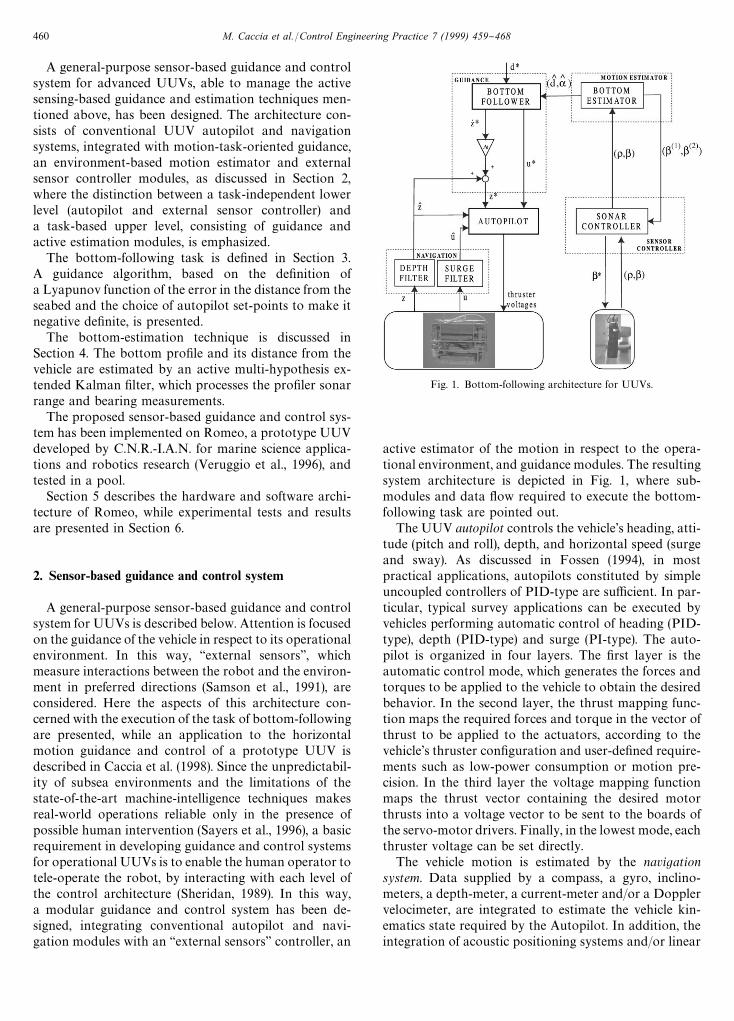
Here, the task of bottom-following is de"ned as navi-gating at a "xed distance from the seabed, represented asan arbitrary surface whose characteristics may or maynot be known. The interactions between the UUV andthe seabed are measured by range data supplied bya high-frequency pencil-beam pro"ling sonar, sweepingthe bottom pro"le along the vehicle's longitudinal direc-tion. Fig. 2 depicts a UUV moving in the proximity of the
Fig. 2. Nomenclature for a bottom-following UUV.
M. Caccia et al./Control Engineering Practice 7 (1999) 459}468 461
seabed. De"ne z and u as the vehicle depth and surge,respectively, d as the distance of the vehicle from thebottom, a as the bottom slope, and o and b as the sonarrange and bearing, respectively.
Since this research is focused on high-precision bot-tom-following for operational open-frame UUVs, whichare generally structurally stable in pitch and roll, thevehicle pitch in not considered.
Referring to Fig. 2, the guidance task of bottom-following can be described by the function
e"d!d*, (1)
where d* is the desired vehicle distance from the seabed.It is possible to write the following Lyapunov function
of the task variable e, which represents the distance error:
<"12e2"1
2(d!d*)2. (2)
Since the speed of the vehicle in the direction perpendicu-lar to the bottom pro"le is (see Fig. 2)
dQ"!zR cos a!u sin a, a3A!n2
,n2B , (3)
the "rst time derivative of < can be expressed as
<Q "!(d!d*)(zR cos a#u sin a), u'0, (4)
where the vehicle is assumed to move forward, i.e. u'0.<Q is negative de"nite if
zR cos a#u sin a"k (d!d*), k'0, u'0, (5)
where k is a given constant.Eq. (5) is satis"ed by choosing
u*"vN cos a
zR *"!vN sin a#kd!d*
cos a, vN'0,
(6)
where vN is the "xed vehicle speed in the direction parallelto the bottom pro"le, and the term k (d!d*)/cosa com-pensates for the bottom distance error. Of course, in realapplications this component is saturated, obtaining
u*"vN cos a,
zR *"!vN sin a#satw Ak
d!d*
cos a B ,(7)
where satw
stands for the saturation function, i.e.,
satw(x)"G
!w if x(!w,
x if Dx D)w,
w if x'w.
(8)
Since <*0 and <Q )0, for the Barbalat lemmalim
t?=< (t)"0, which complete the proof of conver-
gence.The reference heave value computed in Eq. (7) is trans-
formed into the desired depth for the UUV autopilot on
the basis of the estimated vehicle depth according to thefollowing relation:
z*"zL#zR **t, (9)
where z* and zL are, respectively, the reference and esti-mated depth, and *t is the sampling time.
4. Bottom estimation
Referring to Fig. 2, the bottom estimator state andmeasurement equations are
d(k#1)"d (k)#dQ (k)*t,
dQ (k#1)"dQ (k)#wdQ (k),
a(k#1)"a (k)#wa (k),
(10)
o(k)"d (k)
cos [bk!a (k)]
#l (k) (11)
which represent a linear system with a nonlinear andtime-varying measurement channel a!ected by noise. Thenoise l is supposed to be Gaussian at zero mean andcovariance R. The measurement equation is a function ofthe pro"ler bearing b
kwhich can be actively controlled
by the motion-estimation module. The system noisewdQ takes account of the slow changes in the vehicle depth,
whose measurement is not considered by this "lter.The state of system (10) can be estimated by an ex-
tended Kalman "lter, in consideration of the good resultsobtained in Cristi et al. (1996) and Caccia et al. (1997).The state noise wa allows the "lter to follow gradualchanges in the bottom slope. However, particularly bigvalues of wa make the estimate more sensitive tomeasurement noise, so the resulting "lter is unable tofollow sudden slope changes without prejudicing high-precision estimation.
This problem can be tackled successfully by applyingan active multi-hypothesis approach.
This approach basically consists of three actions:
1. track the current surface which approximates thebottom pro"le;
2. detect a change in the bottom slope;3. estimate the new slope and go back to action 1.
In nominal conditions, the active estimator controls thepro"ler bearing on the basis of the current estimate of thebottom slope and of the memorized last tracked surface.The pro"ling sonar sweeps a sector centered orthogon-ally to the tracked re#ecting surface:
b(1)"aL !*b, b(2)"aL #*b, (12)
where b(1) and b(2) are the swept sector extremes, *b theswept sector semi-amplitude, and aL the estimated bottomslope. In addition, the active estimator memorizes the
462 M. Caccia et al./Control Engineering Practice 7 (1999) 459}468
last tracked surface slope. The pro"ler is forced to moveforward every time the last tracked surface is detected.This feature-related control of the pro"ling sonar totrack the current estimated surface allows the e!ects ofthe linearization of the measurement equation to bereduced, to avoid the alternate tracking of di!erent surfa-ces and to minimize the presence of many missed sonarechoes when the vehicle follows a descending pro"le(Caccia et al., 1997).
The problem of detecting any change in the bottompro"le and estimating the new slope of the bottom sur-face is successfully faced by means of a normalized squareinnovation test and a multi-hypothesis approach.
Calling [dL dQ L aL ] the estimated state, the innovationand its covariance are de"ned as
e(k/k!1)"o (k)!dL (k/k!1)
cos [bk!aL (k/k!1)]
(13)
and
Sk@k~1
"Hk@k~1
Pk@k~1
HTk@k~1
#R, (14)
where Hk@k~1
indicates the measurement matrix, com-puted as the Jacobian of the channel function evaluatedat the predicted state, and P
k@k~1is the one-step predic-
tion covariance.When the normalized square innovation
e(k/k!1)S~1k@k~1
e (k/k!1) (15)
exceeds a threshold (which can be selected either on thebasis of a chi-square distribution (Bar-Shalom and Fort-mann, 1988) or heuristically), the measurement at timek is not considered as having originated from the trackedre#ecting surface (Maksarov and Durrant-White, 1995).In this case the measurement can either be an outlier, orcorrespond to a new re#ecting surface, whose slope hasto be evaluated. Where the measurement is an outlier, itis rejected, and the "lter performs a prediction step.
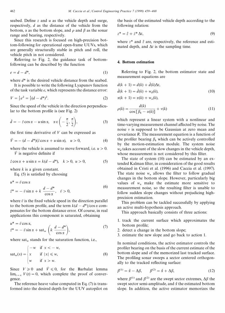
To make a decision about the nature of an unpredictedmeasurement, a bank of n EKFs corresponding to di!er-ent sea-bed slopes and to a measurement outlier is trig-gered and run for m steps (decision interval). Then, anArbiter determines the new bottom slope, evaluatinga cost function of each "lter residual:
"lterk@k
"argmini
m+j/0
e2i(k!j/k!j!1), (16)
where
i3[0 . . n]W<
with
<"Mi : ei( j/j!1)S~1
i( j/j!1)e
i, ( j/j!1)(d
∀j3[k!m, k]N. (17)
< is the set of valid hypotheses after m measurements, i.e.of the hypotheses that satisfy a normalized square in-novation test at each step of the decision interval.
Since no &&a priori'' information is available on thebottom pro"le, it is not guaranteed that any hy-pothesized slope will correspond to the real one. A rea-sonable criterion to tackle this problem is to "x a step *ain the slope variation, and run n"2p#1 "lters withinitialized slopes corresponding to
aL !p*a,2 , aL !*a, aL , aL #*a, . . aL #p*a (18)
(where aL is the current estimated slope and p a positiveinteger) and the uncertainty in the slope estimation is ofthe order of *a. The ith hypothesis "lter is initialized with
dLi"dL cos(aL
i)/cos(aL ). (19)
The resulting active multi-hypothesis EKF bottom-estimator scheme is shown in Fig. 3.
5. Application: Romeo bottom follower
The active sonar-based bottom-following system de-scribed in the previous sections has been tested onRomeo, an open-frame tethered UUV, designed and de-veloped by the Robotics Department of C.N.R.-I.A.N. forshallow water (up to 500 m depth) marine science ap-plications, and for research in the "eld of intelligentvehicles. In particular, Romeo has been designed to sat-isfy marine scientists' requirements of carrying di!erentkinds of payloads, acquiring real-time high-quality videoimages, and maneuvering with high precision in the prox-imity of the seabed and man-made underwater structures(Nokin, 1994). To guarantee high precision and agility inmaneuvering, great attention has been devoted to pro-pulsion, seeking to ensure maximum controllability andprecision on the horizontal plane, while keeping pitchand roll to a minimum. Complete motion controllabilityis enabled by four horizontal and four vertical thrusters.In addition, environment-based guidance and motion-estimation systems enable the vehicle to perform auto-matically a number of basic motion tasks in scienti"cmissions.
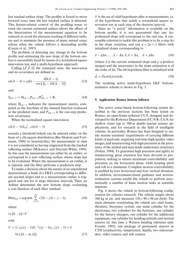
Fig. 4 shows the vehicle in bottom-following con"g-uration for robotics research. The vehicle weighs about380 kg in air, and measures 130]90]96 cm (lwh). Themain elements constituting the vehicle are: steel frame,thrusters, buoyancy system, one main cylinder for theelectronics, two cylinders for the batteries, one cylinderfor the battery chargers, one cylinder for the additionalequipment, one cylinder for heading/attitude and inertialsensors (at this time a Watson heading reference unit;Everett, 1995), one package of permanent sensors asCTD (conductivity, temperature, depth), two echosoun-ders, video camera and still camera.
M. Caccia et al./Control Engineering Practice 7 (1999) 459}468 463
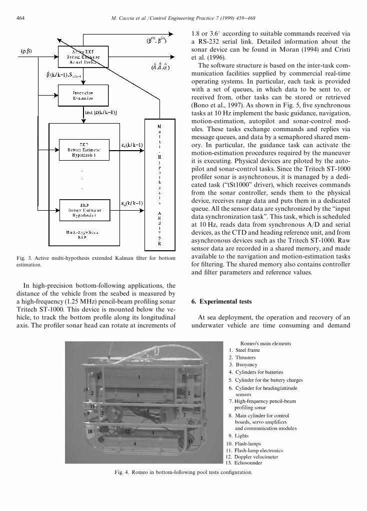
Fig. 4. Romeo in bottom-following pool tests con"guration.
Fig. 3. Active multi-hypothesis extended Kalman "lter for bottomestimation.
In high-precision bottom-following applications, thedistance of the vehicle from the seabed is measured bya high-frequency (1.25 MHz) pencil-beam pro"ling sonarTritech ST-1000. This device is mounted below the ve-hicle, to track the bottom pro"le along its longitudinalaxis. The pro"ler sonar head can rotate at increments of
1.8 or 3.63 according to suitable commands received viaa RS-232 serial link. Detailed information about thesonar device can be found in Moran (1994) and Cristiet al. (1996).
The software structure is based on the inter-task com-munication facilities supplied by commercial real-timeoperating systems. In particular, each task is providedwith a set of queues, in which data to be sent to, orreceived from, other tasks can be stored or retrieved(Bono et al., 1997). As shown in Fig. 5, "ve synchronoustasks at 10 Hz implement the basic guidance, navigation,motion-estimation, autopilot and sonar-control mod-ules. These tasks exchange commands and replies viamessage queues, and data by a semaphored shared mem-ory. In particular, the guidance task can activate themotion-estimation procedures required by the maneuverit is executing. Physical devices are piloted by the auto-pilot and sonar-control tasks. Since the Tritech ST-1000pro"ler sonar is asynchronous, it is managed by a dedi-cated task (&&tSt1000'' driver), which receives commandsfrom the sonar controller, sends them to the physicaldevice, receives range data and puts them in a dedicatedqueue. All the sensor data are synchronized by the &&inputdata synchronization task''. This task, which is scheduledat 10 Hz, reads data from synchronous A/D and serialdevices, as the CTD and heading reference unit, and fromasynchronous devices such as the Tritech ST-1000. Rawsensor data are recorded in a shared memory, and madeavailable to the navigation and motion-estimation tasksfor "ltering. The shared memory also contains controllerand "lter parameters and reference values.
6. Experimental tests
At sea deployment, the operation and recovery of anunderwater vehicle are time consuming and demand
464 M. Caccia et al./Control Engineering Practice 7 (1999) 459}468
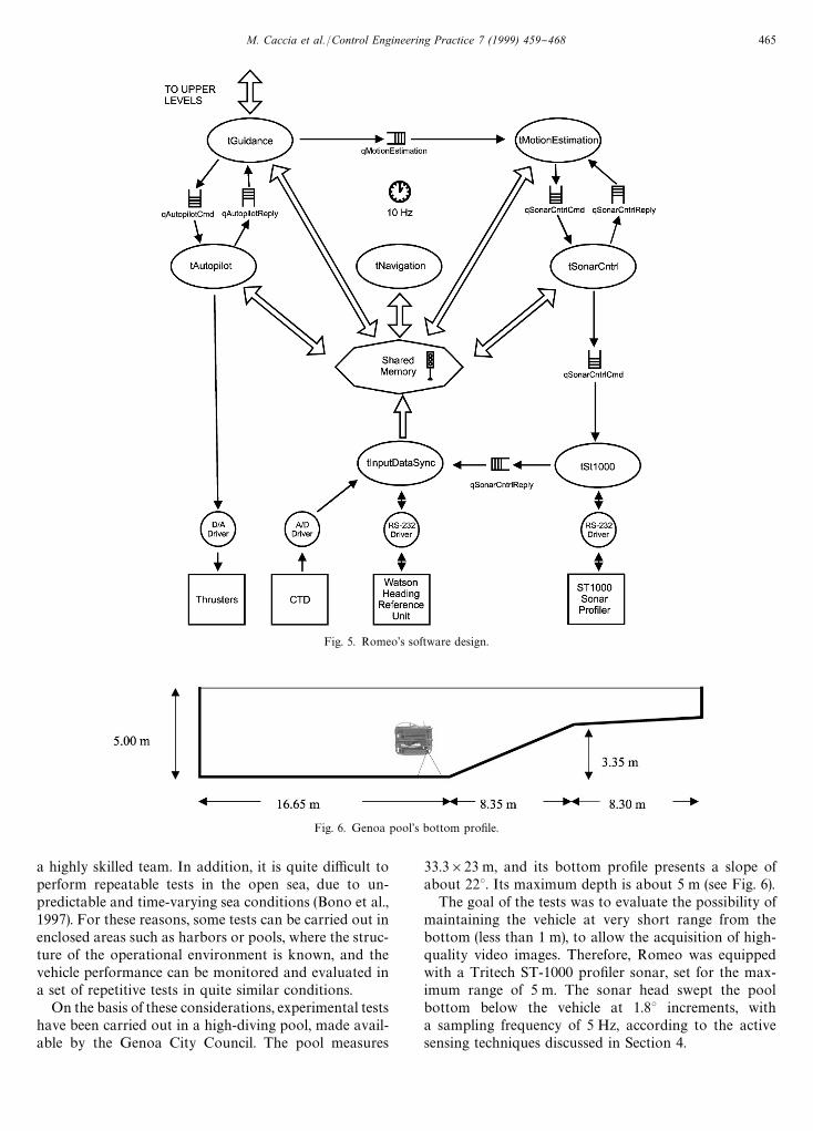
Fig. 5. Romeo's software design.
Fig. 6. Genoa pool's bottom pro"le.
a highly skilled team. In addition, it is quite di$cult toperform repeatable tests in the open sea, due to un-predictable and time-varying sea conditions (Bono et al.,1997). For these reasons, some tests can be carried out inenclosed areas such as harbors or pools, where the struc-ture of the operational environment is known, and thevehicle performance can be monitored and evaluated ina set of repetitive tests in quite similar conditions.
On the basis of these considerations, experimental testshave been carried out in a high-diving pool, made avail-able by the Genoa City Council. The pool measures
33.3]23 m, and its bottom pro"le presents a slope ofabout 223. Its maximum depth is about 5 m (see Fig. 6).
The goal of the tests was to evaluate the possibility ofmaintaining the vehicle at very short range from thebottom (less than 1 m), to allow the acquisition of high-quality video images. Therefore, Romeo was equippedwith a Tritech ST-1000 pro"ler sonar, set for the max-imum range of 5 m. The sonar head swept the poolbottom below the vehicle at 1.83 increments, witha sampling frequency of 5 Hz, according to the activesensing techniques discussed in Section 4.
M. Caccia et al./Control Engineering Practice 7 (1999) 459}468 465
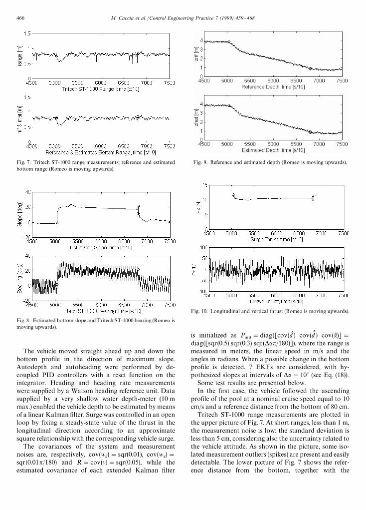
Fig. 7. Tritech ST-1000 range measurements; reference and estimatedbottom range (Romeo is moving upwards).
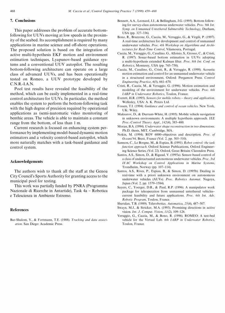
Fig. 8. Estimated bottom slope and Tritech ST-1000 bearing (Romeo ismoving upwards).
The vehicle moved straight ahead up and down thebottom pro"le in the direction of maximum slope.Autodepth and autoheading were performed by de-coupled PID controllers with a reset function on theintegrator. Heading and heading rate measurementswere supplied by a Watson heading reference unit. Datasupplied by a very shallow water depth-meter (10 mmax.) enabled the vehicle depth to be estimated by meansof a linear Kalman "lter. Surge was controlled in an openloop by "xing a steady-state value of the thrust in thelongitudinal direction according to an approximatesquare relationship with the corresponding vehicle surge.
The covariances of the system and measurementnoises are, respectively, cov(w
dR )"sqr(0.01), cov(wa)"
sqr(0.01n/180) and R"cov(l)"sqr(0.05), while theestimated covariance of each extended Kalman "lter
Fig. 9. Reference and estimated depth (Romeo is moving upwards).
Fig. 10. Longitudinal and vertical thrust (Romeo is moving upwards).
is initialized as P*/*5
"diag([cov(dL ) cov(dQ L ) cov(aL )]"diag([sqr(0.5) sqr(0.3) sqr(*an/180)]), where the range ismeasured in meters, the linear speed in m/s and theangles in radians. When a possible change in the bottompro"le is detected, 7 EKFs are considered, with hy-pothesized slopes at intervals of *a"103 (see Eq. (18)).
Some test results are presented below.In the "rst case, the vehicle followed the ascending
pro"le of the pool at a nominal cruise speed equal to 10cm/s and a reference distance from the bottom of 80 cm.
Tritech ST-1000 range measurements are plotted inthe upper picture of Fig. 7. At short ranges, less than 1 m,the measurement noise is low: the standard deviation isless than 5 cm, considering also the uncertainty related tothe vehicle attitude. As shown in the picture, some iso-lated measurement outliers (spikes) are present and easilydetectable. The lower picture of Fig. 7 shows the refer-ence distance from the bottom, together with the
466 M. Caccia et al./Control Engineering Practice 7 (1999) 459}468
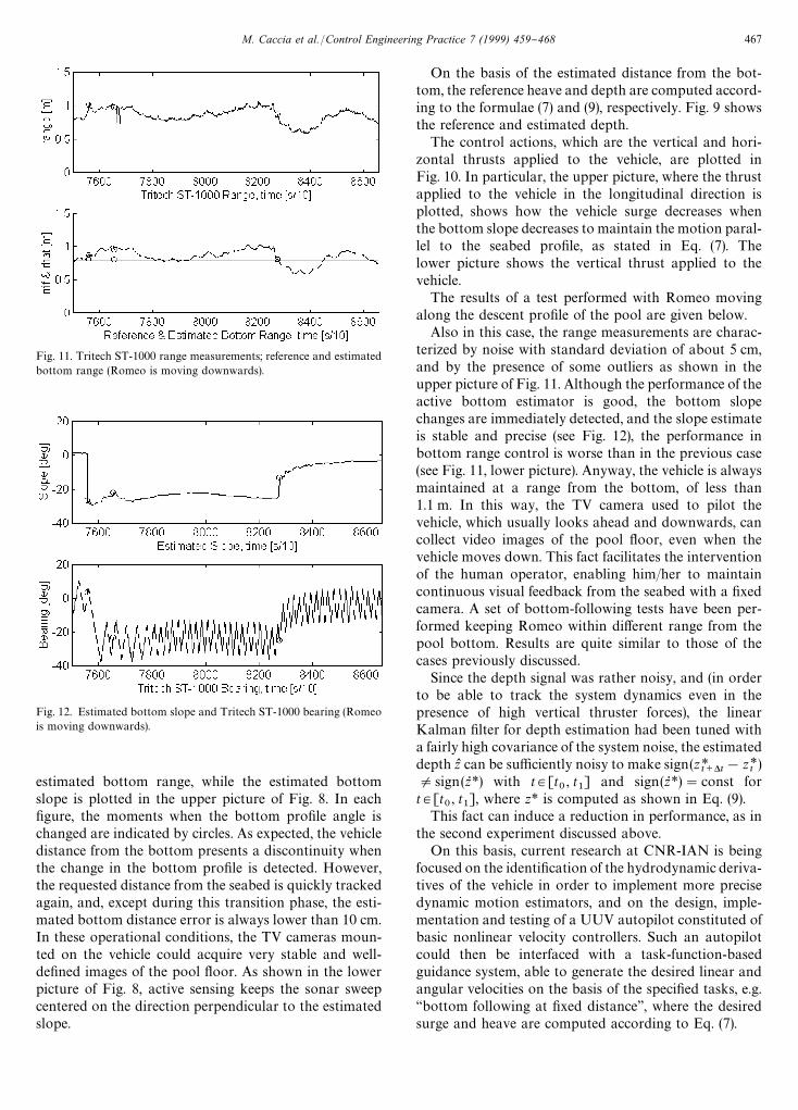
Fig. 11. Tritech ST-1000 range measurements; reference and estimatedbottom range (Romeo is moving downwards).
Fig. 12. Estimated bottom slope and Tritech ST-1000 bearing (Romeois moving downwards).
estimated bottom range, while the estimated bottomslope is plotted in the upper picture of Fig. 8. In each"gure, the moments when the bottom pro"le angle ischanged are indicated by circles. As expected, the vehicledistance from the bottom presents a discontinuity whenthe change in the bottom pro"le is detected. However,the requested distance from the seabed is quickly trackedagain, and, except during this transition phase, the esti-mated bottom distance error is always lower than 10 cm.In these operational conditions, the TV cameras moun-ted on the vehicle could acquire very stable and well-de"ned images of the pool #oor. As shown in the lowerpicture of Fig. 8, active sensing keeps the sonar sweepcentered on the direction perpendicular to the estimatedslope.
On the basis of the estimated distance from the bot-tom, the reference heave and depth are computed accord-ing to the formulae (7) and (9), respectively. Fig. 9 showsthe reference and estimated depth.
The control actions, which are the vertical and hori-zontal thrusts applied to the vehicle, are plotted inFig. 10. In particular, the upper picture, where the thrustapplied to the vehicle in the longitudinal direction isplotted, shows how the vehicle surge decreases whenthe bottom slope decreases to maintain the motion paral-lel to the seabed pro"le, as stated in Eq. (7). Thelower picture shows the vertical thrust applied to thevehicle.
The results of a test performed with Romeo movingalong the descent pro"le of the pool are given below.
Also in this case, the range measurements are charac-terized by noise with standard deviation of about 5 cm,and by the presence of some outliers as shown in theupper picture of Fig. 11. Although the performance of theactive bottom estimator is good, the bottom slopechanges are immediately detected, and the slope estimateis stable and precise (see Fig. 12), the performance inbottom range control is worse than in the previous case(see Fig. 11, lower picture). Anyway, the vehicle is alwaysmaintained at a range from the bottom, of less than1.1 m. In this way, the TV camera used to pilot thevehicle, which usually looks ahead and downwards, cancollect video images of the pool #oor, even when thevehicle moves down. This fact facilitates the interventionof the human operator, enabling him/her to maintaincontinuous visual feedback from the seabed with a "xedcamera. A set of bottom-following tests have been per-formed keeping Romeo within di!erent range from thepool bottom. Results are quite similar to those of thecases previously discussed.
Since the depth signal was rather noisy, and (in orderto be able to track the system dynamics even in thepresence of high vertical thruster forces), the linearKalman "lter for depth estimation had been tuned witha fairly high covariance of the system noise, the estimateddepth zL can be su$ciently noisy to make sign(z*
t`*t!z*t)
Osign(zR *) with t3[t0, t
1] and sign(zR *)"const for
t3[t0, t
1], where z* is computed as shown in Eq. (9).
This fact can induce a reduction in performance, as inthe second experiment discussed above.
On this basis, current research at CNR-IAN is beingfocused on the identi"cation of the hydrodynamic deriva-tives of the vehicle in order to implement more precisedynamic motion estimators, and on the design, imple-mentation and testing of a UUV autopilot constituted ofbasic nonlinear velocity controllers. Such an autopilotcould then be interfaced with a task-function-basedguidance system, able to generate the desired linear andangular velocities on the basis of the speci"ed tasks, e.g.&&bottom following at "xed distance'', where the desiredsurge and heave are computed according to Eq. (7).
M. Caccia et al./Control Engineering Practice 7 (1999) 459}468 467
7. Conclusions
This paper addresses the problem of accurate bottom-following for UUVs moving at low speeds in the proxim-ity of the seabed. Its accomplishment is required by manyapplications in marine science and o!-shore operations.The proposed solution is based on the integration ofactive multi-hypothesis EKF motion and environmentestimation techniques, Lyapunov-based guidance sys-tems and a conventional UUV autopilot. The resultingbottom-following architecture can operate on a largeclass of advanced UUVs, and has been operationallytested on Romeo, a UUV prototype developed byC.N.R.-I.A.N.
Pool test results have revealed the feasibility of themethod, which can be easily implemented in a real-timecontrol architecture for UUVs. In particular, the methodenables the system to perform the bottom-following taskwith the high degree of precision required by operationalapplications as (semi-)automatic video monitoring ofbenthic areas. The vehicle is able to maintain a constantrange from the bottom, of less than 1 m.
Current research is focused on enhancing system per-formance by implementing model-based dynamic motionestimators and a velocity control-based autopilot, whichmore naturally matches with a task-based guidance andcontrol system.
Acknowledgements
The authors wish to thank all the sta! at the GenoaCity Council's Sports Authority for granting access to themunicipal pool for testing.
This work was partially funded by PNRA (ProgrammaNazionale di Ricerche in Antartide), Task 4a } Roboticae Telescienza in Ambiente Estremo.
References
Bar-Shalom, Y., & Fortmann, T.E. (1988). ¹racking and data associ-ation. San Diego: Academic Press.
Bennett, A.A., Leonard, J.J., & Bellingham, J.G. (1995). Bottom follow-ing for survey-class autonomous underwater vehicles. Proc. 9th Int.Symp. on ;nmanned ;ntethered Submersible ¹echnology, Durham,USA (pp. 327}336).
Bono, R., Bruzzone, G., Caccia, M., Veruggio, G., & Virgili, P. (1997).A real-time architecture for development and control of unmannedunderwater vehicles. Proc. 4th =orkshop on Algorithms and Archi-tectures for Real-¹ime Control, Vilamoura, Portugal.
Caccia, M., Veruggio, G., Casalino, G., Alloisio, S., Grosso, C., & Cristi,R. (1997). Sonar-based bottom estimation in UUVs adoptinga multi-hypothesis extended Kalman "lter. Proc. 8th Int. Conf. onRobotics, Monterey, USA (pp. 745}750).
Caccia, M., Casalino, G., Cristi, R., & Veruggio, R. (1998). Acousticmotion estimation and control for an unmanned underwater vehiclein a structured environment, Oxford: Pergamon Press. ControlEngineering Practice, 6(5), 661}670.
Cristi, R., Caccia, M., & Veruggio, G. (1996). Motion estimation andmodeling of the environment for underwater vehicles. Proc. 6thIARP in ;nderwater Robotics, Toulon, France.
Everett, H.R. (1995). Sensors for mobile robots } theory and application.Wellesley, USA: A. K. Peters Ltd.
Fossen, T.I. (1994). Guidance and control of ocean vehicles. New York,UK: Wiley.
Maksarov, D., & Durrant-White, H. (1995). Mobile vehicle navigationin unknown environments: A multiple hypothesis approach. IEEProc.-Control ¹heory Appl., 142(4), 385}400.
Moran, B.A. (1994).;nderwater shape reconstruction in two dimensions.Ph.D. thesis, MIT, Cambridge, MA.
Nokin, M. (1994). ROV 6000}objectives and description. Proc. ofOceans194, Brest, France (Vol. 2, pp. 505}510).
Samson, C., Le Borgne, M., & Espiau, B. (1991). Robot control: the taskfunction approach. Oxford Science Publications, Oxford Engineer-ing Science Series, (Vol. 22). Oxford, Great Britain: Clarendon Press.
Santos, A.S., Simon, D., & Rigaud, V. (1995a). Sensor-based control ofa class of underactuated autonomous underwater vehicles. Proc. 3rdIFAC =orkshop on Control Applications in Marine Systems,Trondheim, Norway (pp. 107}114).
Santos, A.S., Rives, P., Espiau, B., & Simon, D. (1995b). Dealing inreal-time with a priori unknown environment on autonomousunderwater vehicles (AUVs). Proc. Robotics Automat. Nagoya,Japan (Vol. 2, pp. 1579}1584).
Sayers, C., Yoerger, D.R., & Paul, R.P. (1996). A manipulator workpackage for teleoperation from unmanned untethered vehicles}current feasibility and future applications. Proc. 6th Int. Adv.Robotic Program, Toulon, France.
Sheridan, T.B. (1989). Telerobotics. Automatica, 25 (4), 487}507.Swayn, M.J., & Stricker, M.A. (1993). Promising directions in active
vision. Int. J. Comput. <ision, 11(2), 109}126.Veruggio, G., Caccia, M., & Bono, R. (1996). ROMEO: A test-bed
vehicle for the Virtual Lab. 6th IARP in ;nderwater Robotics,Toulon, France.
468 M. Caccia et al./Control Engineering Practice 7 (1999) 459}468
Related Documents