International Journal of Power System Operation and Energy Management, ISSN ( PRINT ): 2231–4407, Volume-1, Issue-2, 2011 83 Active & Reactive Power Control Of A Doubly Fed Induction Generator Driven By A Wind Turbine Srinath Vanukuru & Sateesh Sukhavasi DVR & Dr HS MIC College of Technology, Kanchikacherla, Vijayawada, Krishna (Dt), Andhra Pradesh, India. E-mail : srinathvanukuru@gmail.com, sateeshsukhavasi@gmail .com Abstract - Wind Energy is gaining interest now-a – days as one of the most important renewable sources of energy due to its ecofriendly nature. But the major disadvantage lies in variable speed wind generation and this paper gives a study on control of Wind driven doubly fed Induction Generators. The speeds above and below Synchronous speeds are obtained using a bidirectional power flow converter. By using thi s reactive power is controlled and hence the overall Power factor of sy stem can b e kept at unity under varying load conditions. . This paper presents simulation results of a Grid-connected DFIG. A switch-by-switch representation of the PWM converters with a carrier-based Sinusoidal PWM modulation for both rotor- and stator-side converter has been proposed. Stator-Flux Oriented vector cont rol approach is deployed for b oth stator- and rotor-side converters to provide independent control of active and reactive power and keep the DC-link voltage constant. A 7.5 KW generator is designed and its effectiveness in controlling is verified in different operating conditions i.e. above and below synchronous speeds. Key words - DFIG; Grid side Converter(GSC); Rotor Side Converter(RSC); Active and Reactive Powers; Stator Flux Oriented control. I. INTRODUCTION Industrial drive applications are generally classified into constant speed and variable speed operations.For constant speed applications generally ac machines are used where as for variable speed applications dc machines are used.But due to the disadvantages of dc machines lies mainly with commutators and brushes which limit the machine speed and peak current.As a result for variable speed applications ac machines are gaining more imporatance than the dc machines recently. In order to meet power needs, taking into account economical and environmental factors, wind energy conversion is gradually gaining interest as a suitable s ource of renewable energy. With increased penetration of wind power into electrical grids, wind turbines are largely deployed due to their variable speed feature and hence influencing system dynamics. But unbalances in wind energy are highly impacting the energy conversion and this problem can be overcome by using a Doubly Fed Induction Generator (DFIG). Doubly fed wound rotor induction machine with vector control is very attractive to the high performance variable speed drive and generating applications. In variable speed drive application, the so called slip power recovery scheme is a common practice here the power due to the rotor slip below or above synchronous speed is recovered to or supplied from the power source resulting in a highly efficient variable speed system. Slip power control can be obtained by using popular Static Scherbius drive for bi directional power flow. The major advantage of the DFIG is that the power electronic equipment used i.e. a back to back converter that handles a fraction of (20-30%) total system power. The back to back converter consists of two converters i.e. Grid Side Converter (GSC) and Rotor Side Converter (RSC) connected back to back through a dc link capacitor for energy storage purpose. In this paper a control strategy is presented for DFIG. Stator Active and Reactive power control principle is also presented. In order to decouple the active and reactive powers Stator Flux Oriented control is used and hence the induction machine model is developed, PI Controllers design is applied for stator flux oriented reference frame. The simulation model is developed and implemented in MATLAB/SIMULINK software. Fig. 1 : Doubly Fed Ind uction Generator Driven by a Wind Turbine.

Welcome message from author
This document is posted to help you gain knowledge. Please leave a comment to let me know what you think about it! Share it to your friends and learn new things together.
Transcript
8/9/2019 Active & Reactive Power Control
http://slidepdf.com/reader/full/active-reactive-power-control 1/8
International Journal of Power System Operation and Energy Management, ISSN ( PRINT ): 2231–4407, Volume-1, Issue-2, 2011
83
Active & Reactive Power Control Of A Doubly Fed Induction
Generator Driven By A Wind Turbine
Srinath Vanukuru & Sateesh Sukhavasi
DVR & Dr HS MIC College of Technology, Kanchikacherla, Vijayawada, Krishna (Dt), Andhra Pradesh, India.E-mail : [email protected], [email protected]
Abstract - Wind Energy is gaining interest now-a – days as one of the most important renewable sources of energy due to its
ecofriendly nature. But the major disadvantage lies in variable speed wind generation and this paper gives a study on control of
Wind driven doubly fed Induction Generators. The speeds above and below Synchronous speeds are obtained using a bidirectional power flow converter. By using this reactive power is controlled and hence the overall Power factor of system can be kept at unity
under varying load conditions. . This paper presents simulation results of a Grid-connected DFIG. A switch-by-switch representationof the PWM converters with a carrier-based Sinusoidal PWM modulation for both rotor- and stator-side converter has been
proposed. Stator-Flux Oriented vector control approach is deployed for both stator- and rotor-side converters to provide independent
control of active and reactive power and keep the DC-link voltage constant. A 7.5 KW generator is designed and its effectiveness incontrolling is verified in different operating conditions i.e. above and below synchronous speeds.
Key words - DFIG; Grid side Converter(GSC); Rotor Side Converter(RSC); Active and Reactive Powers; Stator Flux Oriented
control.
I. INTRODUCTION
Industrial drive applications are generally classified
into constant speed and variable speed operations.Forconstant speed applications generally ac machines are
used where as for variable speed applications dc
machines are used.But due to the disadvantages of dcmachines lies mainly with commutators and brushes
which limit the machine speed and peak current.As aresult for variable speed applications ac machines are
gaining more imporatance than the dc machines
recently. In order to meet power needs, taking into
account economical and environmental factors, windenergy conversion is gradually gaining interest as a
suitable source of renewable energy. With increased
penetration of wind power into electrical grids, windturbines are largely deployed due to their variable speed
feature and hence influencing system dynamics. But
unbalances in wind energy are highly impacting theenergy conversion and this problem can be overcome by
using a Doubly Fed Induction Generator (DFIG).
Doubly fed wound rotor induction machine withvector control is very attractive to the high performance
variable speed drive and generating applications. In
variable speed drive application, the so called slip powerrecovery scheme is a common practice here the power
due to the rotor slip below or above synchronous speed
is recovered to or supplied from the power sourceresulting in a highly efficient variable speed system. Slip
power control can be obtained by using popular StaticScherbius drive for bi directional power flow. The major
advantage of the DFIG is that the power electronic
equipment used i.e. a back to back converter that
handles a fraction of (20-30%) total system power. The
back to back converter consists of two converters i.e.Grid Side Converter (GSC) and Rotor Side Converter
(RSC) connected back to back through a dc link
capacitor for energy storage purpose.
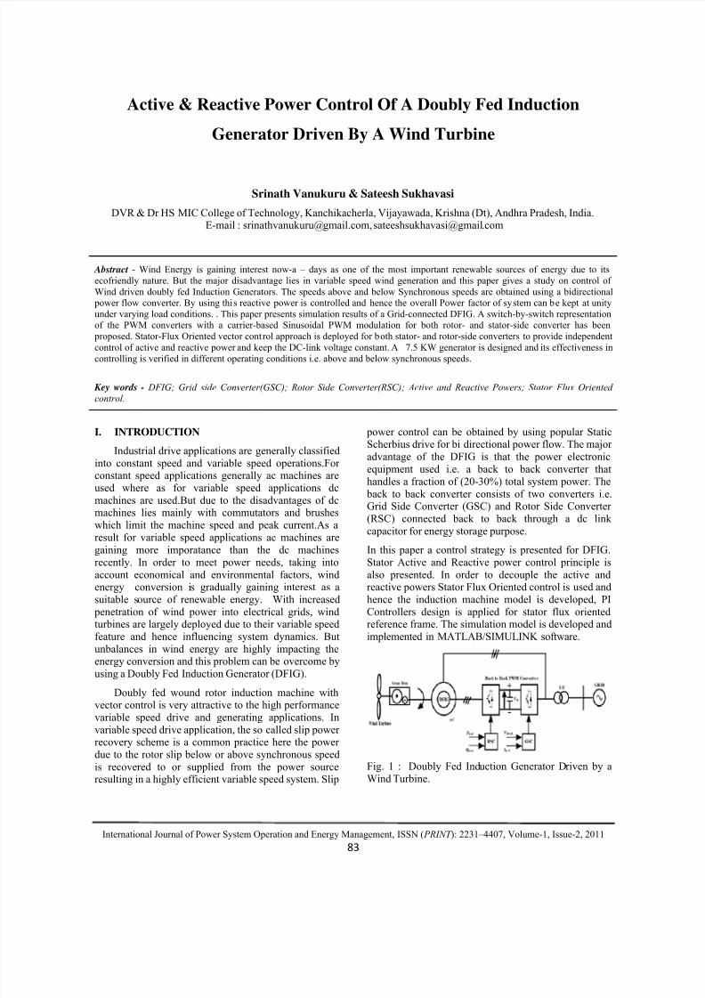
In this paper a control strategy is presented for DFIG.
Stator Active and Reactive power control principle is
also presented. In order to decouple the active andreactive powers Stator Flux Oriented control is used and
hence the induction machine model is developed, PI
Controllers design is applied for stator flux orientedreference frame. The simulation model is developed and
implemented in MATLAB/SIMULINK software.
Fig. 1 : Doubly Fed Induction Generator Driven by a
Wind Turbine.
8/9/2019 Active & Reactive Power Control
http://slidepdf.com/reader/full/active-reactive-power-control 2/8
Active & Reactive Power Control Of A Doubly Fed Induction Generator Driven By A Wind Turbine
International Journal of Power System Operation and Energy Management, ISSN ( PRINT ): 2231–4407, Volume-1, Issue-2, 2011
84
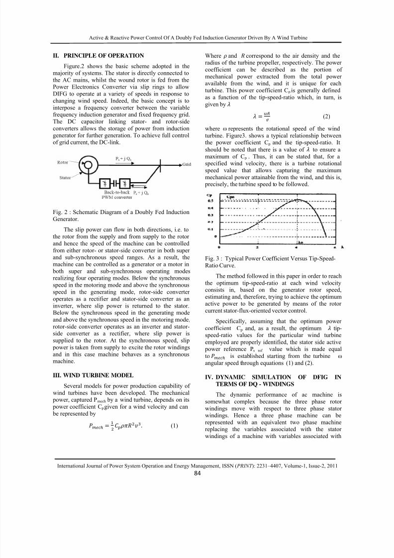
II. PRINCIPLE OF OPERATION
Figure.2 shows the basic scheme adopted in themajority of systems. The stator is directly connected to
the AC mains, whilst the wound rotor is fed from thePower Electronics Converter via slip rings to allow
DIFG to operate at a variety of speeds in response to
changing wind speed. Indeed, the basic concept is to
interpose a frequency converter between the variablefrequency induction generator and fixed frequency grid.
The DC capacitor linking stator- and rotor-side
converters allows the storage of power from inductiongenerator for further generation. To achieve full control
of grid current, the DC-link.
Fig. 2 : Schematic Diagram of a Doubly Fed Induction
Generator.
The slip power can flow in both directions, i.e. to
the rotor from the supply and from supply to the rotor
and hence the speed of the machine can be controlled
from either rotor- or stator-side converter in both superand sub-synchronous speed ranges. As a result, the
machine can be controlled as a generator or a motor in
both super and sub-synchronous operating modesrealizing four operating modes. Below the synchronous
speed in the motoring mode and above the synchronous
speed in the generating mode, rotor-side converteroperates as a rectifier and stator-side converter as an
inverter, where slip power is returned to the stator.Below the synchronous speed in the generating mode
and above the synchronous speed in the motoring mode,
rotor-side converter operates as an inverter and stator-side converter as a rectifier, where slip power is
supplied to the rotor. At the synchronous speed, slip
power is taken from supply to excite the rotor windings
and in this case machine behaves as a synchronousmachine.
III. WIND TURBINE MODEL
Several models for power production capability of
wind turbines have been developed. The mechanical power, captured Pmech by a wind turbine, depends on its
power coefficient C p given for a wind velocity and can
be represented by . (1)
Where and correspond to the air density and theradius of the turbine propeller, respectively. The power
coefficient can be described as the portion of
mechanical power extracted from the total poweravailable from the wind, and it is unique for each
turbine. This power coefficient C p is generally defined
as a function of the tip-speed-ratio which, in turn, isgiven by (2)
where ω represents the rotational speed of the wind
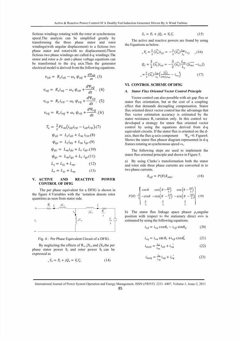
turbine. Figure3. shows a typical relationship betweenthe power coefficient C p and the tip-speed-ratio. It
should be noted that there is a value of to ensure a
maximum of C p . Thus, it can be stated that, for aspecified wind velocity, there is a turbine rotational
speed value that allows capturing the maximum
mechanical power attainable from the wind, and this is, precisely, the turbine speed to be followed.
Fig. 3 : Typical Power Coefficient Versus Tip-Speed-
Ratio Curve.
The method followed in this paper in order to reach
the optimum tip-speed-ratio at each wind velocityconsists in, based on the generator rotor speed,
estimating and, therefore, trying to achieve the optimumactive power to be generated by means of the rotor
current stator-flux-oriented vector control.
Specifically, assuming that the optimum power
coefficient C p and, as a result, the optimum tip-speed-ratio values for the particular wind turbine
employed are properly identified, the stator side active power reference Ps ref value which is made equal
to is established starting from the turbine ω
angular speed through equations (1) and (2).
IV. DYNAMIC SIMULATION OF DFIG IN
TERMS OF DQ - WINDINGS
The dynamic performance of ac machine is
somewhat complex because the three phase rotor
windings move with respect to three phase statorwindings. Hence a three phase machine can be
represented with an equivalent two phase machinereplacing the variables associated with the stator
windings of a machine with variables associated with
8/9/2019 Active & Reactive Power Control
http://slidepdf.com/reader/full/active-reactive-power-control 3/8
Active & Reactive Power Control Of A Doubly Fed Induction Generator Driven By A Wind Turbine
International Journal of Power System Operation and Energy Management, ISSN ( PRINT ): 2231–4407, Volume-1, Issue-2, 2011
85
fictious windings rotating with the rotor at synchronous
speed.The analysis can be simplified greatly bytransforming the three phase stator and rotor
windings(with angular displacement) to a fictious two
phase stator and rotor(with no displacement).Thesefictious two phase windings are called d-q windings.The
stotor and rotor a-,b- and c-phase voltage equations can be transformed to the d-q axis.Then the generator
electrical model is derived from the following equations.
. (3)
Ψ . 4
Ψ . 5
Ψ
.6
. (7) . (8) . (9) . (10) (11) . (12)
(13)
V. ACTIVE AND REACTIVE POWERCONTROL OF DFIG
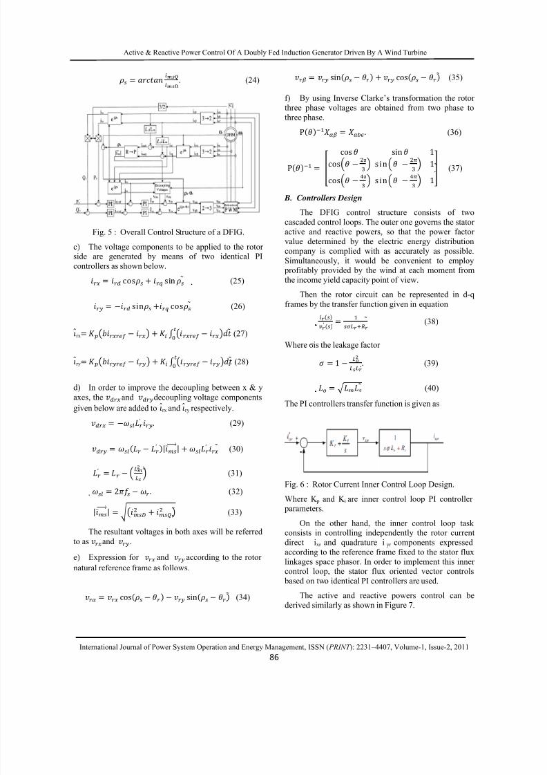
The per phase equivalent for a DFIG is shown in
the figure 4.Variables with the ‘notation denote rotorquantities as seen from stator side.
Fig. 4 : Per Phase Equivalent Circuit of a DFIG.
By neglecting the effects of R s, jXls and jXlr the per
phase stator power Ss and rotor power Sr can be
expressed as
. (14)
. (15)
The active and reactive powers are found by using
the Equations as below.
(16)
32 32 | |
| | (17)
VI. CONTROL SCHEME OF DFIG
A. Stator Flux Oriented Vector Control Principle
Vector control can also possible with air gap flux orstator flux orientation, but at the cost of a coupling
effect that demands decoupling compensation. Stator
flux oriented direct vector control has the advantage thatflux vector estimation accuracy is estimated by the
stator resistance R s variation only. In this control wedeveloped a strategy for stator flux oriented vectorcontrol by using the equations derived from d-q
equivalent circuits. If the stator flux is oriented on the d-
axis, then the flux q-axis component Ψqs =0. Figure4.Shows the stator flux phasor diagram represented in d-q
frames rotating at synchronous speed ωs.
The following steps are used to implement thestator flux oriented principle and shown in Figure 5.
a) By using Clarke’s transformation both the stator
and rotor side three phase currents are converted in totwo phase currents.
. (18)
cos cos π cos π sin sin π sin π (19)
b) The stator flux linkage space phasor angular
position with respect to the stationary direct axis is
estimated by using the following equations. cos sin . (20)
sin cos (21) (22)
(23)
8/9/2019 Active & Reactive Power Control
http://slidepdf.com/reader/full/active-reactive-power-control 4/8
Active & Reactive Power Control Of A Doubly Fed Induction Generator Driven By A Wind Turbine
International Journal of Power System Operation and Energy Management, ISSN ( PRINT ): 2231–4407, Volume-1, Issue-2, 2011
86
. (24)
Fig. 5 : Overall Control Structure of a DFIG.
c) The voltage components to be applied to the rotorside are generated by means of two identical PI
controllers as shown below.
cos sin (25)
sin cos (26)
rx (27)
ry (28)
d) In order to improve the decoupling between x & y
axes, the
and
decoupling voltage components
given below are added to rx and ry respectively. ′ . (29)
′ | | ′ (30)
′ (31)
2 . (32)
| | (33)
The resultant voltages in both axes will be referred
to as and .
e) Expression for and according to the rotor
natural reference frame as follows.
cos sin (34)
sin cos (35)
f) By using Inverse Clarke’s transformation the rotor
three phase voltages are obtained from two phase to
three phase.
P . (36)
P cos sin 1cos π s in 1cos π s in 1 (37)
B. Controllers Design
The DFIG control structure consists of two
cascaded control loops. The outer one governs the stator
active and reactive powers, so that the power factor
value determined by the electric energy distribution
company is complied with as accurately as possible.
Simultaneously, it would be convenient to employ
profitably provided by the wind at each moment fromthe income yield capacity point of view.
Then the rotor circuit can be represented in d-q
frames by the transfer function given in equation
′ (38)
Where σ is the leakage factor
1 . (39)
(40)
The PI controllers transfer function is given as
Fig. 6 : Rotor Current Inner Control Loop Design.
Where K p and K i are inner control loop PI controller parameters.
On the other hand, the inner control loop taskconsists in controlling independently the rotor current
direct ixr and quadrature i yr components expressedaccording to the reference frame fixed to the stator flux
linkages space phasor. In order to implement this innercontrol loop, the stator flux oriented vector controls
based on two identical PI controllers are used.
The active and reactive powers control can be
derived similarly as shown in Figure 7.
8/9/2019 Active & Reactive Power Control
http://slidepdf.com/reader/full/active-reactive-power-control 5/8
Active & Reactive Power Control Of A Doubly Fed Induction Generator Driven By A Wind Turbine
International Journal of Power System Operation and Energy Management, ISSN ( PRINT ): 2231–4407, Volume-1, Issue-2, 2011
87
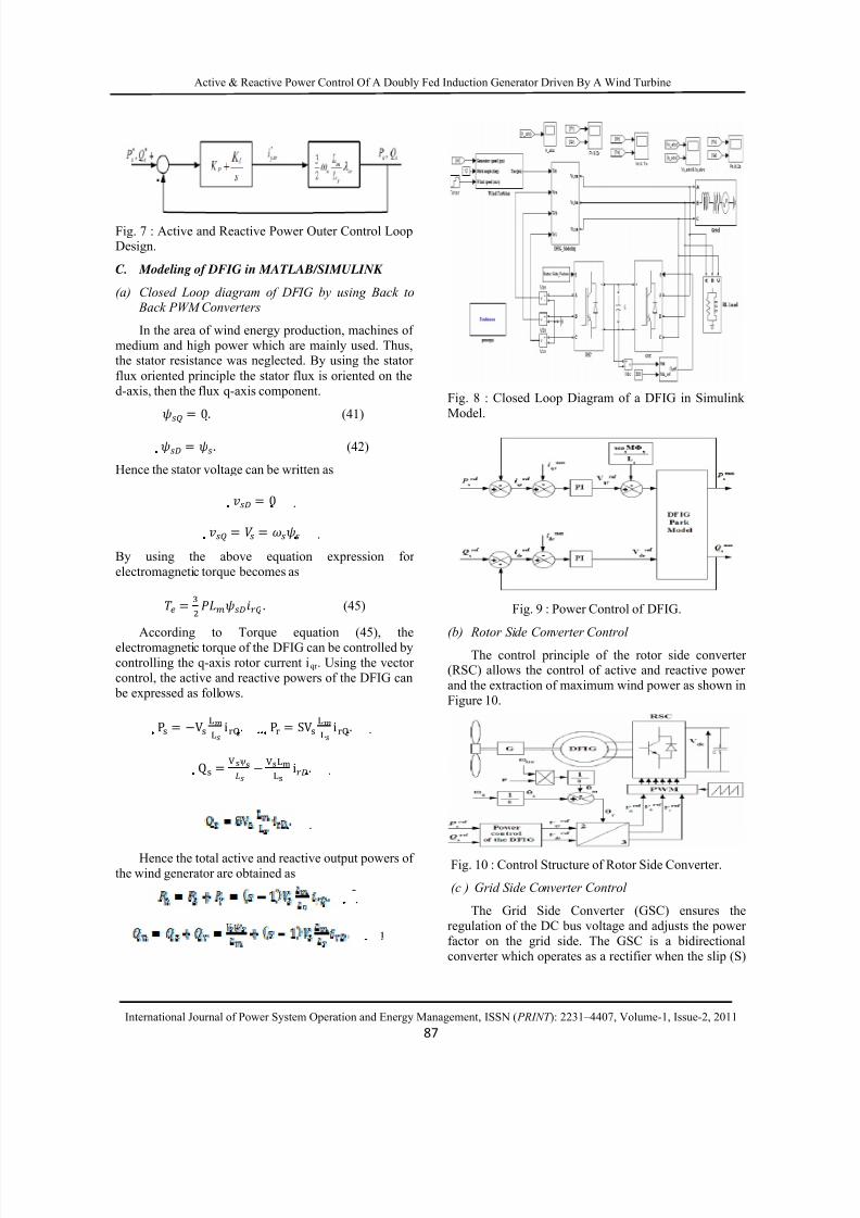
Fig. 7 : Active and Reactive Power Outer Control LoopDesign.
C. Modeling of DFIG in MATLAB/SIMULINK
(a) Closed Loop diagram of DFIG by using Back to Back PWM Converters
In the area of wind energy production, machines of
medium and high power which are mainly used. Thus,the stator resistance was neglected. By using the stator
flux oriented principle the stator flux is oriented on the
d-axis, then the flux q-axis component.
0. (41)
. (42)
Hence the stator voltage can be written as
0
By using the above equation expression for
electromagnetic torque becomes as
. (45)
According to Torque equation (45), the
electromagnetic torque of the DFIG can be controlled by
controlling the q-axis rotor current iqr . Using the vector
control, the active and reactive powers of the DFIG can
be expressed as follows.
P V i. P SV i.
Q ψ i.
Hence the total active and reactive output powers ofthe wind generator are obtained as
Fig. 8 : Closed Loop Diagram of a DFIG in Simulink
Model.
Fig. 9 : Power Control of DFIG.
(b) Rotor Side Converter Control
The control principle of the rotor side converter(RSC) allows the control of active and reactive power
and the extraction of maximum wind power as shown in
Figure 10.
Fig. 10 : Control Structure of Rotor Side Converter.
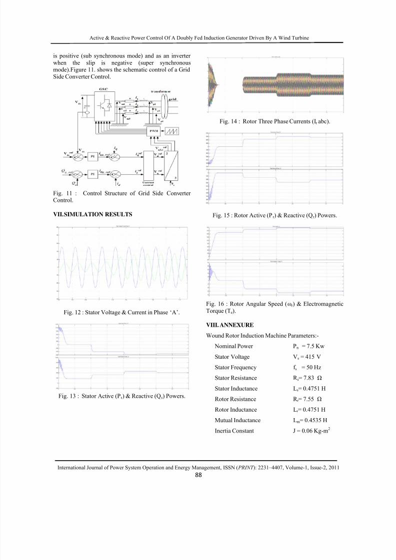
(c ) Grid Side Converter Control
The Grid Side Converter (GSC) ensures the
regulation of the DC bus voltage and adjusts the power
factor on the grid side. The GSC is a bidirectional
converter which operates as a rectifier when the slip (S)
8/9/2019 Active & Reactive Power Control
http://slidepdf.com/reader/full/active-reactive-power-control 6/8
Active & Reactive Power Control Of A Doubly Fed Induction Generator Driven By A Wind Turbine
International Journal of Power System Operation and Energy Management, ISSN ( PRINT ): 2231–4407, Volume-1, Issue-2, 2011
88
is positive (sub synchronous mode) and as an inverter
when the slip is negative (super synchronousmode).Figure 11. shows the schematic control of a Grid
Side Converter Control.
Fig. 11 : Control Structure of Grid Side ConverterControl.
VII. SIMULATION RESULTS
Fig. 12 : Stator Voltage & Current in Phase ‘A’.
Fig. 13 : Stator Active (Ps) & Reactive (Qs) Powers.
Fig. 14 : Rotor Three Phase Currents (Ir abc).
Fig. 15 : Rotor Active (Pr ) & Reactive (Qr ) Powers.
Fig. 16 : Rotor Angular Speed (ωr ) & Electromagnetic
Torque (Te).
VIII. ANNEXURE
Wound Rotor Induction Machine Parameters:-
Nominal Power Pn = 7.5 Kw
Stator Voltage Vs = 415 V
Stator Frequency f s = 50 Hz
Stator Resistance R s = 7.83 Ω
Stator Inductance Ls = 0.4751 H
Rotor Resistance R r = 7.55 Ω
Rotor Inductance Lr = 0.4751 H
Mutual Inductance Lm = 0.4535 H
Inertia Constant J = 0.06 Kg-m2
8/9/2019 Active & Reactive Power Control
http://slidepdf.com/reader/full/active-reactive-power-control 7/8
Active & Reactive Power Control Of A Doubly Fed Induction Generator Driven By A Wind Turbine
International Journal of Power System Operation and Energy Management, ISSN ( PRINT ): 2231–4407, Volume-1, Issue-2, 2011
89
Number of Pair of Poles P =2
Rating Speed Nr = 1440rpm.
IX. CONCLUSION
The simulation results obtained when running the
wind generator and its overall control system model presented in this paper, correspond strictly to those that
of a real doubly fed induction generator working in a
wind farm. The results are obtained for differentoperating conditions such as sub synchronous and super
synchronous speeds when the speed of the wind turbine
changes periodically for the given input. Hence from
these results we can determine that for super
synchronous speeds the torque is negative (generating)and for sub synchronous speeds it is positive
(motoring).As a result the active & reactive powers are
controlled by using the stator flux oriented principlewhich yields the better results. The machine side
provides good decoupling between active and reactive
powers.
A. NOMENCLATUREv, v Stator and rotor voltagesi, i Stator and rotor currents
ψ, ψ Stator and rotor flux linkagesL, X Machine magnetizing inductance, ReactanceL, L Stator and rotor per phase winding inductancesL, L Stator and rotor per phase leakage inductancesR, R Stator and rotor per phase winding resistances
σ
Leakage factor
S, S Stator and rotor apparent powerP, P Stator and rotor active powerQ, Q Stator and rotor reactive powerP, Wind Turbine net active & reactive powersf Grid frequencyı Stator magnetizing current space phasor
modulus|ı | Rotor current space phasor modulus
P Stator side active power reference value
Q Stator side reactive power reference valuei, i Direct-and quadrature-axis rotor current
components respectively expressed in the
stator-flux-oriented reference framei , i Reference values of the rotor current ,
components, respectively
iα, iβ Direct- and Quadrature – axis rotor current
components respectively expressed in the rotor
natural reference frameiD, i Direct – and quadrature- axis stator current
components respectively, expressed in the
stationary reference framei, i Direct – and quadrature – axis stator current
components respectively, expressed in the
stator- flux- oriented reference frameK, K Inner loop vector controller PI compensator
parametersK, K Outer loop vector controller PI compensator
parametersiD, i Direct- quadrature-axis stator magnetizing
current components respectively, expressed inthe stationary reference frame
v, v Direct- and quadrature- axis rotor decouplingvoltage components, respectively, expressed in
the stator- flux- oriented reference framev, v Direct- and quadrature- axis rotor voltage
components, respectively, expressed in the
stator- flux- oriented reference framevα, vβ Direct- and quadrature- axis rotor voltage
components, respectively, expressed in the
rotor natural reference frame|ı | Stator voltage space phasor modulusvD, v Direct- and quadrature- axis stator voltage
components, respectively, expressed in the
stationary reference frame
ρ Phase angle of stator flux- linkage space phasor
with respect to the direct – axis of the
stationary reference frame
ω Angular slip frequencyvD, v Direct- and quadrature- axis rotor voltage
components, respectively, expressed in the
stationary reference framev DC Link Voltage Reference Valuei Quadrature axis reference current
v Stator voltage at Phase Av Stator voltage at Phase Bv Stator voltage at Phase C
B. SUFFICES, SUPERSCRIPTS
s, r Stator, rotor
8/9/2019 Active & Reactive Power Control
http://slidepdf.com/reader/full/active-reactive-power-control 8/8
Active & Reactive Power Control Of A Doubly Fed Induction Generator Driven By A Wind Turbine
International Journal of Power System Operation and Energy Management, ISSN ( PRINT ): 2231–4407, Volume-1, Issue-2, 2011
90
, β , β Stationary reference frame
d, q d-q reference frame
x, y x, y stator-flux-oriented reference frame
a,b,c Three-phase reference
REFERENCES
[1] Brahim Nait-kaci, Mamadou L. Doumbia,
“Active and Reactive power control of a doublyfed induction generator for wind applications”,
IEEE 2009. (reference1).
[2] Arantxa Tapia, Gerardo Tapia, J. Xabier
Ostolaza, “Modeling and Control of a Wind
Turbine Driven doubly fed Induction Generator”,
IEEE 2003. (reference2).
[3] C. Eisenhut, F. Krug, C. Schram and B. Klockl,“Wind Turbine Model for System Simulations
Near Cut-in Wind Speed” IEEE Trans, on Energy
Conversion, June 2007, vol. 22, 414-420.
[4] T.K.A. Brekken “A Novel Control Scheme for a
Doubly-Fed Induction Wind Generator under
Unbalanced Grid Voltage Condition.” 2005.
[5] A. Peterson “Analysis, Modeling and Control ofDoubly fed Induction Generators for Wind
Turbines,” in Energy and Environment. 2005,
PhD Dissertation thesis, Chalmers University of
Technology: Goteborg.
[6] J. Morren, J.T.G. Pierik, S.W.H. De Haan, J.
Bozelie, “Grid Interaction of offshore WindFrames. Part 1. Models for Dynamic Simulation,”
Wind Energy, 8(3), July-Sep 2005.
[7] A.D. Hanseen, “Generator and power electronicsfor wind turbine” Chapter in Wind Power in
Power Systems, John Wiley and sons Ltd., 2004
[8] L. Holdsworth, Wu. XG, J.B. Ekanayake, N.Jenkins, “Comparison of fixed speed and doubly-
fed Induction Wind Turbines during Power
System Disturbances.” IEE Proceedings:Generation, Transmission, Distribution, 2003,
343-352.
[9] A. Tapia “Modeling and Control of a
wind turbine driven doubly fed inductiongenerator.” Energy Conversion, IEEE
Transaction on, 2003, 194-204.
[10] W.L. Kling and J.G. Slootweg, “Wind Turbines
as Power Plants” in Proceeding of the IEEE Wind
Power and the impacts on Power Systems June
2002, 17-18, Oslo, Norway.
[11] JM. Rodriguez, “Incidence on Power System
dynamics of high penetration of fixed speed and
doubly fed wind energy systems,” IEEETransaction on Power Systems, 2002, 1089-1095.
[12] S. Wade, M.W. Dunnigan, and B.W. Williams,“Modeling and simulation of induction machine
vector control with rotor resistance
identification,” IEEE Trans. Power Electron., vol.12, pp. 495- 50, May 1997.
[13] D.J. Atkinson, R.A. Larkin, and R. Jones, “A
vector-controlled doubly- fed induction generatorfor a variable- speed wind turbine application,”
Trans, Inst, Meas, Contr., vol.19, no. 1, 2-12,
1997.
[14] R.S. Pena, J.C. Clare, and G.M. Asher, “Vectorcontrol of a variable speed doubly-fed induction
machine for wind generation system, EPEJ” vol.
6, no 3-4, 60-67, Dec.1996.
[15] R. Pena, J.C. Clare, G.M. Asher, “Double fed
Induction generator using back-to-back PWM
converters and its application to variable-speedwind-energy generation”. Electric Power
Applications, IEE Proceedings 1996. 143(3),
231-241.[16] W.C. Xu “Torque and reactive power control of a
Doubly-Fed induction machine by Position
sensor less scheme”. IEEE Trans. IndustrialApplications, 1995. 31(3), 636-642.
Related Documents