Active cells for redundant and configurable articulated structures John P Swensen 1 , Ahsan I Nawroj 1 , Paul E I Pounds 2 and Aaron M Dollar 3 1 Department of Mechanical Engineering and Materials Science, Yale University, 9 HillHouse Avenue, Mason Lab 110, New Haven, CT 06511, USA 2 The School of Information Technology and Electrical Engineering, University of Queensland, Australia 3 Department of Mechanical Engineering and Materials Science, Yale University, 15 Prospect Street, New Haven, CT 06511, USA E-mail: [email protected], [email protected], [email protected] and aaron. [email protected] Received 31 January 2014, revised 8 April 2014 Accepted for publication 1 May 2014 Published 12 September 2014 Abstract The proposed research effort explores the development of active cells—simple contractile electro-mechanical units that can be used as the material basis for larger articulable structures. Each cell, which might be considered a ‘muscle unit,’ consists of a contractile Nitinol Shape Memory Alloy (SMA) core with conductive terminals. Large numbers of these cells might be combined and externally powered to change phase, contracting to either articulate with a large strain or increase the stiffness of the ensemble, depending on the cell design. Unlike traditional work in modular robotics, the approach presented here focuses on cells that have a simplistic design and function, are inexpensive to fabricate, and are eventually scalable to sub-millimeter sizes, working toward our vision of articulated and robotic structures that can be custom- fabricated from large numbers of general cell units, similar to biological structures. In this paper, we present the design of the active cells and demonstrate their usage with three articulated structures built with them. Keywords: active structures, modular robot, shape-memory alloy (Some figures may appear in colour only in the online journal) 1. Introduction The focus of this paper is in the creation of a class of articulated structures from simple ‘robotic’ cells. While the approach has elements similar to work in modular robotics, the described work greatly differs in the simplicity of the cells and their ability to scale in terms of size of construction. These cells (shown in figure 1) are intentionally simplistic such that they are easy to fabricate (with a very small number of parts) and also hold the promise that the principal concept can be scaled to be much smaller in size (eventually sub- millimeter scale). The long-term goal of the project is the development of electromechanical composite materials made of a large number of tiny contractile engineered cells that serve as the building blocks for larger articulated or variable- stiffness structures (e.g. figure 2). This cell-based approach, which has been largely overlooked in engineered systems, is ubiquitous in biology—groups of similar cells form tissues, groups of tissues form organs, and groups of organs form complex organisms. There has been a fairly large amount of research in modular and reconfigurable robots, the majority of which rely on ‘units’ that are self-contained robots themselves, complete with their own suite of actuators (generally for mobility), sensors, and control electronics, resulting in systems with fundamental lower limits on the sizes that can be achieved. Alternatively, we are working toward a much simpler concept of electromechanical units that we call ‘active cells,’ inspired by biological systems wherein essentially all multicellular organisms are comprised of specialized cells that together form complex systems. As a specific example of where many similar specialized cells are co-located, the human heart is comprised of only two active-cell types (myocardiocytes and cardiac pacemaker cells) within the extracellular matrix [1], 0964-1726/14/104003+10$33.00 © 2014 IOP Publishing Ltd Printed in the UK 1 Smart Materials and Structures Smart Mater. Struct. 23 (2014) 104003 (10pp) doi:10.1088/0964-1726/23/10/104003

Welcome message from author
This document is posted to help you gain knowledge. Please leave a comment to let me know what you think about it! Share it to your friends and learn new things together.
Transcript

Active cells for redundant and configurablearticulated structures
John P Swensen1, Ahsan I Nawroj1, Paul E I Pounds2 and Aaron M Dollar3
1Department of Mechanical Engineering and Materials Science, Yale University, 9 HillHouse Avenue,Mason Lab 110, New Haven, CT 06511, USA2The School of Information Technology and Electrical Engineering, University of Queensland, Australia3Department of Mechanical Engineering and Materials Science, Yale University, 15 Prospect Street, NewHaven, CT 06511, USA
E-mail: [email protected], [email protected], [email protected] and [email protected]
Received 31 January 2014, revised 8 April 2014Accepted for publication 1 May 2014Published 12 September 2014
AbstractThe proposed research effort explores the development of active cells—simple contractileelectro-mechanical units that can be used as the material basis for larger articulable structures.Each cell, which might be considered a ‘muscle unit,’ consists of a contractile Nitinol ShapeMemory Alloy (SMA) core with conductive terminals. Large numbers of these cells might becombined and externally powered to change phase, contracting to either articulate with a largestrain or increase the stiffness of the ensemble, depending on the cell design. Unlike traditionalwork in modular robotics, the approach presented here focuses on cells that have a simplisticdesign and function, are inexpensive to fabricate, and are eventually scalable to sub-millimetersizes, working toward our vision of articulated and robotic structures that can be custom-fabricated from large numbers of general cell units, similar to biological structures. In this paper,we present the design of the active cells and demonstrate their usage with three articulatedstructures built with them.
Keywords: active structures, modular robot, shape-memory alloy
(Some figures may appear in colour only in the online journal)
1. Introduction
The focus of this paper is in the creation of a class ofarticulated structures from simple ‘robotic’ cells. While theapproach has elements similar to work in modular robotics,the described work greatly differs in the simplicity of the cellsand their ability to scale in terms of size of construction.These cells (shown in figure 1) are intentionally simplisticsuch that they are easy to fabricate (with a very small numberof parts) and also hold the promise that the principal conceptcan be scaled to be much smaller in size (eventually sub-millimeter scale). The long-term goal of the project is thedevelopment of electromechanical composite materials madeof a large number of tiny contractile engineered cells thatserve as the building blocks for larger articulated or variable-stiffness structures (e.g. figure 2). This cell-based approach,which has been largely overlooked in engineered systems, is
ubiquitous in biology—groups of similar cells form tissues,groups of tissues form organs, and groups of organs formcomplex organisms.
There has been a fairly large amount of research inmodular and reconfigurable robots, the majority of which relyon ‘units’ that are self-contained robots themselves, completewith their own suite of actuators (generally for mobility),sensors, and control electronics, resulting in systems withfundamental lower limits on the sizes that can be achieved.Alternatively, we are working toward a much simpler conceptof electromechanical units that we call ‘active cells,’ inspiredby biological systems wherein essentially all multicellularorganisms are comprised of specialized cells that togetherform complex systems. As a specific example of where manysimilar specialized cells are co-located, the human heart iscomprised of only two active-cell types (myocardiocytes andcardiac pacemaker cells) within the extracellular matrix [1],
0964-1726/14/104003+10$33.00 © 2014 IOP Publishing Ltd Printed in the UK1
Smart Materials and Structures
Smart Mater. Struct. 23 (2014) 104003 (10pp) doi:10.1088/0964-1726/23/10/104003

with skeletal muscle generally comprised of a single myocytetype within an extracellular matrix.
In a previous work, we studied the design of the con-ductive surfaces of contractile cells utilized in large groups tocreate large conductive structures [2], experimentallydemonstrating purely conductive structures consisting ofhundreds of cells with passive cell-to-cell contacts [3], anddesigning methods of creating active cells with parallel biaselements [4, 5]. In this paper, we extend that work byexploring the development of the contractile aspect of the cell,investigating the implementation of active material actuatorelements (Nitinol Shape Memory Alloy (SMA)) andantagonist passive springs, implemented in modular cellblocks that are reconfigurable. While Nitinol has limitationsin terms of thermodynamic inefficiencies and achievablebandwidth, it has relatively good achievable strain and ismore durable than other material actuators [6]. Materialactuators are generally desirable due to their potential to beutilized at very small scales, simple powering schemes
(through Joule heating for Nitinol), and the lack of requiredcomplicated complementary structures (in contrast to com-mon Lorentz force actuators, for example, which generallyrequire bearings, magnets, and a physical or electronic meansof commutation between coils). As with the biological musclecells, these simple and largely homogeneous cells aresimultaneously structural and contractile, but unlike mostmodular robots, are neither self-assembling nor self-reconfiguring.
Nearly all existing approaches to modular robots can beclassified as either being very general purpose (with thenecessary attendant complexity) or simple but mostly passivecomponents. In terms of the former, there have been a numberof very impressive projects involving highly capable general-purpose modular robots, including CKBots [7] and SMORES[8]. Additionally, much of the theoretical consideration formodular and cellular robotics was presented by Fukuda andUeyama [9], which parlays into the expanding field ofcooperative and distributed robotics (e.g. [10, 11]). Thoroughreviews of the work in the area prior to 2009 are foundin [12, 13].
On the spectrum of the simpler modular robot projects,roBlocks [14] (later commercialized as Cubelets by ModularRobotics LLC), are single-function blocks but are not parti-cularly simple in terms of design. A related approach tosimple, crystalline-based robots that achieved volume changethrough linear actuators in all directions was developed byRus and Vona [15]. Recent examples of simple modules thatare mostly passive, e.g. they only deal with latching andunlatching, are given by Moses and Chirikjian [16], Gilpinet al [17], and Tolley et al [18]. Perhaps the most impressive,more general-purpose modular robot to date is called ‘Mill-Moteins’ [19]—this seems to be the first effort that hasachieved scales on the order of 1 cm per module and hasactuation, rather than just latching.
Unlike these and other related work, we are workingtoward very simple modular ‘cells’ that are both structural andcontractile, with an eye toward eventual miniaturization andeasy mass production. We begin this paper with a descriptionof the design of the Nitinol-based contractile element of the
Smart Mater. Struct. 23 (2014) 104003 J P Swensen et al
Figure 1. An exploded view of the assembly of an active cell (left)and a fully assembled cell (right). Each Nitinol coil and pass-throughwire, with their copper terminals, are prepared previously toassembly. Then, the brass tubing is attached to the inner end-cappiece and the magnets are attached to the outer end-cap piece withcyanoacrylate. The final step is simple assembly of the constituentpieces.
Contraction
Direction ofmovementFriction area
Relaxation
Friction area
Contraction Contraction
Friction area
Ventrical diastole(contraction)
atrial systole(relaxation)
Artificial heart “Skeletal” muscle Peristaltic locomotion Deformable airfoil
Figure 2. Potential applications—muscle contraction in the heart (left), peristaltic locomotion in earthworms (center), and whole aircraftdeformation (right).
2

cell (section 2), followed by a description of the design of themechanical cell housing and electrical interconnects(section 3). Next, we present several proof-of-conceptexperimental demonstrations of a small groups of cells,arranged in various configurations as active structures: aparallel platform, an inchworm robot, and a rolling structure(section 4). We conclude with a discussion on the contribu-tions and limitations of the current approach and identify thenext steps for future work (section 5).
2. Cell contractile element
The choice of SMA Nitinol as the primary method ofactuation, coupled with the goal of a minimalist approach toengineering the structure of the active cells, sets forth specificdesign challenges. Nitinol has fundamental limitation in termsof thermodynamic efficiency [20]; however several efforts inboth miniaturization [21–23] and micro-machining or laseretching [24–26] has shown Nitinol to be feasible for makingscalable actuators, as opposed to magnetic or electrostaticactuation methods that have fundamental challenges at verysmall scales. The choice of Nitinol also drives many of thedesign decisions, such as the mechanical design of the cell,spring selection for a return force for the one-way SMAspring coils, and cell interconnects and mating, which areaddressed in the following.
2.1. SMA—Nitinol
The desired eventual scale of the actuator cells (<10 mm)places strict limits on the complexity of the actuationmechanism, making an active-material actuator attractive (asopposed to a small electric motor, for instance). Our currentconcept exploits the shape memory effect of nickel-titanium(NiTi) SMAs. SMAs have the distinct advantage of beinghighly compact and requiring little overhead in terms of driveelectronics. The direct electrical interfacing and ease of inte-gration make them apropos for this application. NiTi, themost widely available SMA, can exert high forces and sustainlarge stresses when the ends of a NiTi wire are constrainedand transitioned from the martensitic to austenitic phase [27].Conversely, many other active material actuators, such aselectro-active polymers and piezoelectric cells, allow eitherlimited stresses or very low achievable strains, making themless suitable. NiTi is durable, inexpensive, and can achievelarge strains when heated.
NiTi SMAs have their own inherent limitations, how-ever. The mechanism by which they actuate stems from aphase change phenomenon in which the crystalline lattice ofthe metal transitions from austenitic structure to martensiticstructure on cooling. Heating causes the crystalline domainsto transition to the more compact austenitic lattice form,inducing a strain in the material. In commercial NiTi SMAs,this strain is currently limited to approximately 4% forstraight drawn wire in tension for repeatable, non-deteriorat-ing cycling of the shape memory effect. Additionally, SMA isa unidirectional actuator—an external restoring stress must be
applied to strain it to its detwinned state. The SMA must thenbe heated to revert back to the more-dense austenitic lattice(see figure 3). Despite these limitations, however, we believeit is the most reasonable option for the proposed workbecause it provides the potential for miniaturization (althoughthe engineering challenges of miniaturization are notaddressed in this paper).
Another engineering challenge with using Nitinol iscreating reliable electrical and mechanical connections [28].Nitinol manufacturing involves heat treatment in an oxygenatmosphere, leaving a thick oxide layer that acts as a passi-vation layer and makes it difficult to create reliable conductiveconnections using basic solders. Designers often resort to acombination of either abrasives or etchants, specialized fluxes(like Indalloy Flux #2 or #3, Indium Corporation, 2013), andsubsequent soldering to make a strong mechanical and elec-trical connection. Another common solution is a mechanicalcrimp that scrapes and penetrates the oxide layer to providethe connection.
In our design, we created our own custom Nitinol coils(shown as the black ‘springs’ on the outside of the cells infigure 1) by creating a close winding of 0.3 mm diameterFlexinol wire around 1 mm diameter music wire. By makingcoils, rather than using the manufacturer-provided straightdrawn wire, we are able to trade off the stress and straincapabilities of the Nitinol. The coil on the music wire wasclamped at both ends during heat treatment. To set thememory shape, the coil was heated with a butane torch andquenched in cold water. Although using a torch to bring theNitinol to a temperature through visual inspection of colorchange is much less precise than other techniques involvinghighly controlled ovens, this method did provide the ability toeasily create long lengths of coil, and we still achieved highrepeatability in spring properties across batches of coils (seesection 2.2 for a discussion on return spring optimization).
We cut the coil to the appropriate length, leaving fourextra coils at each end of the length, and pot soldered theNitinol inside a small piece of copper tubing as shown infigure 4. This method is advantageous because the Nitinol coilexits the terminal at an angle consistent with the spring pitchand helps avoid stress concentration and permanent plasticdeformation from occurring near the terminals. The process ofmanufacturing straight-drawn Nitinol wires into spring coilsprovides several design parameters for choosing the twospring stiffnesses for the austenitic and martensitic phases, Ka
and Km, respectively. The ideal model of a wound springspecifies the spring constant as a function of the materialproperties and the geometry, namely
=KGd
N D8, (1)
4
3
where K is the spring constant in N/m, G is the shear modulusof the material, d is the diameter of the Nitinol wire, N is thenumber of turns in the coil, and D is the mean diameter of thecoil. This ideal is valid for both compression and extension,assuming the coil is not at a hard-stop if in compression; it hasnot been extended past the point of allowable detwinning and
Smart Mater. Struct. 23 (2014) 104003 J P Swensen et al
3

entered the region of permanent plastic deformation, andbuckling has not occurred (if in compression). Thus, thespring design can be separated into aspects that are material-dependent, Ga and Gm being the austenitic and martensiticshear moduli into aspects that are geometric, namely the wirediameter, coil diameter, and number of turns. Usually thematerial properties are fixed given a specific forming andannealing process, but the remaining parameters allowed us togenerate Nitinol springs with a wide range of stiffness prop-erties given the geometries of the cell design described pre-viously. After the properties of the Nitinol spring wereidentified, the bias spring selection remained to complete atwo-way Nitinol actuator.
2.2. Bias/return spring selection
One of the most critical aspects of the active-cell design waschoosing a bias/return spring that maximizes the recoverablestrain of the cell. Most designs have relied upon tension
springs for the return spring. Here, we chose to use a springthat is in parallel with the Nitinol springs to make the designmore compact and approximately cubic when in the com-pressed state, whereas the parallel design is much longer andthinner to achieve the same strain. While devices with the biasspring in parallel with the Nitinol spring are kinematicallyidentical to the series design, the parallel spring presented twoother design challenges: (1) the diameters of the return springcoils needed to be fairly large compared to the length of thereturn spring to prevent buckling and (2) we had to find aspring manufacturer that made appropriately designedsprings. Because the spring is in parallel with the Nitinolcoils, this became a problem of first identifying the force-displacement curves for our Nitinol coils for both the auste-nitic and martensitic phases, then choosing a spring with aforce-displacement profile such that the equilibrium positionsmaximized the cell displacement.
Figure 5 illustrates the process of finding a bias springthat provided the maximum recoverable strain of the activecell. In figure 5 (top), the bias return spring has a stiffness ofKs and a rest length of ℓ0. The Nitinol coil has an apparentstiffness in extension of KM when in the martensitic phase andstiffness of KA when in the austenitic phase, with a memorylength of L0. Figure 5 (top left) illustrates that typically therest length of the return spring is longer than the memory restlength of the Nitinol coil. This ensures that the Nitinol coil isalways in tension, while the return spring is always in com-pression. As the ends of the Nitinol coil and the return springare fixed, as shown in figure 5 (top right), the length of thetwo together will achieve a static equilibrium somewhere
Smart Mater. Struct. 23 (2014) 104003 J P Swensen et al
Figure 3. Nitinol SMA activation cycle.
Figure 4. Bonding Nitinol coil to copper electrode through a pot-solder technique in copper tubing. The photo shows a completedsoldered electrode (left) and a tube and coil prepared for bonding(right).
Figure 5. Choosing the return spring for parallel spring configura-tion. The Austenite and Martensite stiffness curves (bottom)represent 3 different Nitinol pieces created in two different batchesof forming and annealing. Spring properties were consistent despitecrude annealing techniques.
4

between L0 and ℓ .0 When the Nitinol is in the martensiticstate, the return spring will detwin the Nitinol coil and thestatic equilibrium will be nearer to ℓ0. However, when theNitinol coil is in the austenitic state, the static equilibrium willbe closer to L .0
This static equilibrium can be seen pictorially in figure 5(bottom). Here, the extension of zero on the x axis indicatesthe memory rest length of the Nitinol, ℓ .0 The red curveindicates the spring stiffness curve of the Nitinol coil as it istensioned while in the austenitic phase. The gray curveindicates the apparent spring stiffness curve of the Nitinol coilas it is tensioned while in the martensitic phase. We say‘apparent’ spring stiffness in this case because as the mar-tensitic coil is extended, it is actually detwinning after a shortperiod of initial elastic deformation, rather than just elasticallydeforming. This can be seen in the plot as we periodicallyrelaxed the martensitic Nitinol coil and it returned to a zeroforce state, but at a different extension offset. The blue lineindicates the spring stiffness of the return spring as it iscompressed from its rest length. In these particular experi-mentally determined curves in figure 5 (bottom), the restlength of the return spring was 34 mm longer than thememory rest length of the Nitinol coil, ℓ − =L 34 mm0 0 . Inthis pictorial formulation, the static equilibrium for both themartenstic and austenitic phases of the Nitinol coil can bedetermined by the points at which the return spring stiffnesscurve intersects each of the martensitic and austenitic coilspring stiffness curves. In this design methodology, therecoverable strain of the active cell will be determined by thetotal travel between the equilibrium points for the cold(martensitic) and hot (austenitic) configurations. The optimi-zation of these coils for the maximum allowable strain, usinglinear springs, was accomplished by determining the max-imum allowable return spring length that would not buckleand then optimizing the stroke length over all possible stiff-nesses of commercially available springs with this desiredlength.
Ideally, one would use a constant force spring withmagnitude near the point where unrecoverable plastic defor-mation begins to occur while in the martensitic phase.However, constant force springs on the scale of the activecells described in this paper (and even smaller moving for-ward) are not readily available. The next best spring selectionthen becomes the spring with the longest rest length andspring constant requisite to intersect the martensitic force-displacement curve near the point where unrecoverable plasticdeformation begins. An important consideration whenchoosing springs is the spring buckling thresholds, which willdetermine the maximum rest length achievable as a functionof both the spring diameter and the amount of compressionthat will occur. Figure 5 shows a repetition of the extensionand release on an Instron testing system (Model 5542, InstronCorporation, Norwood, MA, USA) for both the austenitic andmartensitic phases of the coil. A simple characterization doneprior to the experiments shown in figure 5 was a destructivetest, in which we continued the extension and release proce-dure until the coil began to exhibit permanent plastic
deformation (at ∼15 mm of extension). For this reason, welimited the range of motion caused by the bias spring to cause9–10 mm of travel.
In the experiments described later, we operated theNitinol coils by transitioning between the fully martensiticand fully austenitic phases, but more precise control can beachieved by characterizing the Nitinol actuation hysteresisand controlling the volume fraction of martensite and auste-nite in the coils.
3. Cell structure
3.1. Mechanical structure
The goal is to provide a structural framework that is as simpleas possible and also provides (1) physical structure to eachcell and (2) electrical and mechanical connection pointsbetween adjacent cells. The preliminary design, shown infigure 1, is characterized by a low number of parts, a singlepre-assembly step, and a straightforward final assembly. Eachcell is made up of only two Nitinol coils, two pass-throughwires, two telescoping brass tubes, a bias spring, a magnet,and an inner and an outer end cap. The ends of the Nitinolcoils and the pass-through wires are prepared as shown infigure 4, such that the pot-soldered copper tubing serves asboth the electrical connection between cells and themechanical connection within the cell. Each end cap iscomposed of an inner and outer piece. The inner pieces areattached to the telescoping tubes and have channels for thepass-through wires to be routed through the center of thetubes. The inner end cap has also an alignment feature to keepthe bias spring centered within the telescoping tubes. Themagnet is glued to the outer end cap with cyanoacrylate andthe pass-through wires are attached to the end cap via pressfit; the inner and outer end caps are fitted together. The finalstep is to manually compress the entire cell and insert theNitinol coils into the press-fit features on opposing corners ofthe cell.
Here the parts were made with a three-dimensional (3D)printer to facilitate rapid iteration and modification in theearly stages of this effort. However, all of the parts could haveeasily been constructed as molded (hard polyurethane) ormachined (nylon or PTFE) pieces, which include the tubesthat constrain the motion to a single degree of freedom. Herewe used telescoping brass tubes that are manufactured to beused as close-fitting bearing surfaces.
Nitinol formed as extension springs with the memoryshape set to the fully compressed configuration is a uni-directional actuator. Ohmic heating of the Nitinol and thetransition to the austenitic lattice will return the coil to thefully compressed configuration. But subsequent cooling doesnot generally alter the shape of the Nitinol spring, barring theuse of two-way shape memory effect (TWSME). TheTWSME involves a fairly complicated training process andone of the directions of the two-way effect tends to degradefairly quickly over repeated cycling [20]. For this reason, we
Smart Mater. Struct. 23 (2014) 104003 J P Swensen et al
5

have utilized the one-way shape memory effect and chosen abias/return spring to extend the cell upon cooling.
3.2. Cell interconnects, power distribution, and control
Each end cap contains four of the pot-soldered terminals, twofor the pass-through connections and two for the Nitinol con-nections. A magnet attached to the face of each end cap drawsthe four terminals together. The two pass-through terminals oneach end are spring-loaded to prevent the case wherein man-ufacturing inaccuracies would prevent four planar contactsfrom being made robustly. Because of the four conductivepathways through each cell, we were able to create simplecircuits for the ohmic heating of the Nitinol coils.
We created two channels where an end cap connects theconductive pathways that are on opposite corners of the cells,as shown in an example circuit for a linearly connected groupof cells in figure 6. In this manner, we could set up cyclicpatterns for the activation and relaxation of the active cells.Cells could be created with a single conductive pathway, butthe choice of multiple pathways adds additional functionalitywith minimal added complexity. Other potential measures ofminimal added complexity could involve simple passiveelectronics that makes the activation of active cells dependenton the direction of current flow or the frequency of electricaloscillation. This could allow the ‘addressing’ of individualcells, despite the single pathway and without the need frommicrocontrollers or localized intelligence.
4. Experimental implementation of groups of cells
To demonstrate the versatility of the cell concept to be used ina variety of active structures, three distinct devices createdfrom groups of cells were implemented: a parallel platformmade of three cells, a mobile inchworm made of four cells,and a pentagonal rolling robot made of five cells. In each ofthe configurations, the cells were actuated externally via atether of wires, with power switching appropriately to effec-tuate the necessary sequence of actuation for a particularstructure. The equations and principles governing the motionof the each of the active structures are presented according to
the geometry. The mechanical and physical properties for theexperiment are found in table 1.
4.1. Parallel robot platform made of three active cells
The first active structure created is a simple parallel platformcomposed of three active cells. In the language of parallelmechanisms, the platform can be described as a ‘3-PS’structure with one of the legs fixed and the other two allowedto slide across the surface of the ground. This allows theplatform to be tipped, tilted, and lowered by activating thethree cells that form the legs. Though the cells described inthis paper were optimized for maximum displacement, thecells could alternatively be optimized for maximum varia-bility in stiffness such that the stiffness of the platform couldbe modulated.
Figure 7 represents two different configurations of theplatform, both the nominal structure with all the cells in theuncontracted state (top) as well as a configuration with twocells contracted (bottom). Sequences of platforms of cellscould be chained together to create longer active structure
Smart Mater. Struct. 23 (2014) 104003 J P Swensen et al
Figure 6. An illustration of the controller and conductive pathwayfor a linearly connected group of cells. (ChA=Power Channel A,ChB=Power Channel B, RN=Effective resistance of a Nitinol coil).
Table 1. Active Cell Mechanical Properties
Property Value
Active cell mass 17.775 +/− 0.548 gMaximum tensile force 20.65 NUncontracted length 40.64 mmContracted length 30.48 mmTensile stiffness (martensitic Nitinolcoils)
0.53 N mm−1
Tensile stiffness (austenitic Nitiniolcoils)
3.61 N mm−1
Compressive stiffness 0.11 N mm−1
Figure 7. Two configurations of the parallel robot platforms withlegs composed of active cells. (Top) the nominal configuration withvertical normal. (Bottom) a tipped configuration with two activatedcells.
6
with larger workspaces, such as non-modular solutions shownin [29, 30]. Additionally, combinations of platforms insequence and parallel could be combined to form othervariable geometry trusses.
The position, P, and normal vector, N , of the center ofthe triangular platform, as shown in figure 7, is given as
=+ +
= − × −( ) ( )
PP P P
N P P P P3
(2)
1 2 3
2 1 3 1
where
= ( )P q0,0, ,1 1
= ( )P L q, 0, ,2 12 2
α α= ( )P L L qcos ( ), sin ( ), ,3 13 13 3
= − −( )L L q q ,ij i j2
2
and
⎛⎝⎜
⎞⎠⎟α =
− −− L L L
L Lcos
2. (3)1 23
2132
122
13 12
Here, P P, ,1 2 and P3 are the positions of the points whereeach leg attaches to the platform with respect to some coor-dinate system. The quantities q q, ,
1 2and q
3are the generalized
coordinates describing the length of each leg, and Lij is the
length between the ith and jth leg on the platform. The angleα is the angle of the size of the platform connecting leg 1 andleg 3 from the horizontal.
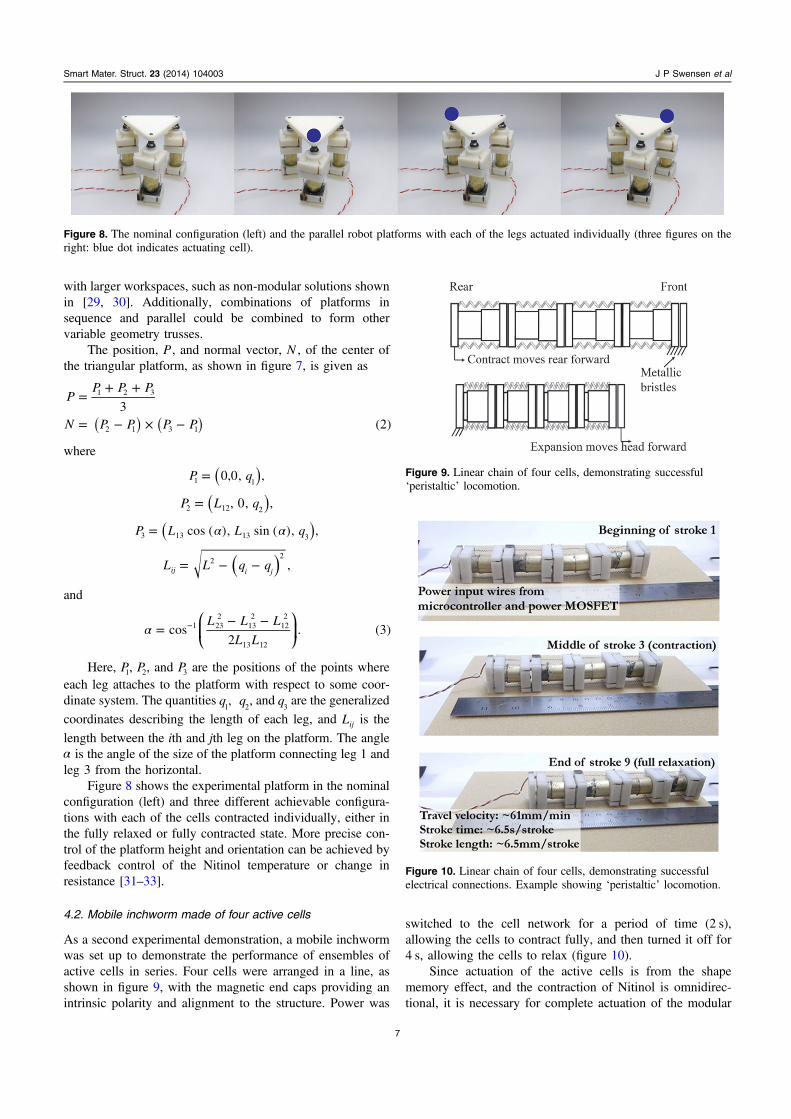
Figure 8 shows the experimental platform in the nominalconfiguration (left) and three different achievable configura-tions with each of the cells contracted individually, either inthe fully relaxed or fully contracted state. More precise con-trol of the platform height and orientation can be achieved byfeedback control of the Nitinol temperature or change inresistance [31–33].
4.2. Mobile inchworm made of four active cells
As a second experimental demonstration, a mobile inchwormwas set up to demonstrate the performance of ensembles ofactive cells in series. Four cells were arranged in a line, asshown in figure 9, with the magnetic end caps providing anintrinsic polarity and alignment to the structure. Power was
switched to the cell network for a period of time (2 s),allowing the cells to contract fully, and then turned it off for4 s, allowing the cells to relax (figure 10).
Since actuation of the active cells is from the shapememory effect, and the contraction of Nitinol is omnidirec-tional, it is necessary for complete actuation of the modular
Smart Mater. Struct. 23 (2014) 104003 J P Swensen et al
Figure 8. The nominal configuration (left) and the parallel robot platforms with each of the legs actuated individually (three figures on theright: blue dot indicates actuating cell).
Figure 9. Linear chain of four cells, demonstrating successful‘peristaltic’ locomotion.
Figure 10. Linear chain of four cells, demonstrating successfulelectrical connections. Example showing ‘peristaltic’ locomotion.
7

robot that cellular actuation be externally directed. To achievethis, a small metallic bristle was added to the end caps of thecells, all aligned in one direction when the cells are assembledend to end. This bristle provides an anisotropic frictionalcontact with the ground [27], allowing the group to inchforward in a peristaltic-like locomotion [28]; thus the entiremotion occurs in the direction allowed by the bristle. Overall,this setup caused the group of four cells to contract and relax,all in one direction because of their aligned bristles in contactwith the ground (made of a rough foam to increase friction).The group of cells forming this modular robot thus moves likean earthworm steadily forward.
The motile performance of the setup is evaluated simplyas the rate of motion of the front (head) of the robot, and thiswas observed to be approximately 60 mmmin−1 (about6.5 mm motion forward in each full contraction and relaxationstroke). Although our experimental setup used direct power-ing of the cells, it is possible to optimize the use of the twopower channels to provide faster locomotion.
4.3. Pentagonal rolling module made of five active cells
The final active structure is a circular deformable robot, withsimilarities to other non-modular examples [34–36]. Thestructure is actuated to roll forward by changing either thecenter of mass or the shape of the perimeter of the rollingstructure. Figure 11 shows the pentagon robot in three distinctshapes used to roll the structure forward (top) and theaccompanying changes in perimeter shape and center of mass(bottom). The center of mass ¯ ¯x y( , ) is calculated, assumingthe center piece and the cells can be represented as pointmasses, as
¯ =∑
+ ∑¯ =
∑
+ ∑=
=
=
=
xmx
M my
my
M m, . (4)i i
i
i i
i
1
5
1
51
5
1
5
where M is the mass of the center piece, m are the masses of
the active cells, and x y( , )i iis the position of the ith cell. The
origin is defined at the middle of the center piece. When a cellis activated, the distance of the modeled point mass from theorigin is decreased, thus affecting the overall center of massof the entire structure and the shape of the enclosingmembrane.
Figure 12 shows the experimental structure made of theactive cells in the same three states as shown in figure 11 atthree different stages of rolling forward. Though more com-plex control schemes with appropriate gaiting patterns couldbe used to provide continuous forward rolling motion, theapproach taken in these experiments was to effectuate rollingin discrete steps using only the three shape changes shown infigure 12.
5. Conclusions and future work
In this paper, we have presented the design and prototype of‘active cells’ and their use in implementing three simplemodular active structures, with each cell being both load-bearing and contractile. Unlike traditional modular robotics,the approach presented here focuses on cells that have asimplistic design and function, are inexpensive to fabricate,and are eventually scalable to sub-millimeter sizes. By usingshape-memory alloy (SMA) with a minimum amount ofengineered structure necessary to provide cell-to-cell trans-mission of power and control, the approach works toward ourvision of actuated structures that can be custom-fabricatedfrom large numbers of general cell units, similar to biologicalstructures.
One key problem remaining relates to the fabrication,modeling, and control of much more complicated articulatedstructures. This may involve both dimensional reductionsfrom a large number of cell positions and orientations tolower dimensional representations of the overall structureshape, as well as better control algorithms to precisely controlcell lengths and stiffnesses. Furthermore, structures that arenot just chains of the cells but also have more materialadhering between cells (akin to biological structures with anextracellular matrix) will require additional consideration inthe mechanics of how cells interact.
The cells presented in this paper have clearly identifiabledesign improvements to improve further experimental use.The current cell design, while showing a large repeatablestrain and having the desired level of mechanical simplicity,requires the connector caps of the cells to be modified in orderto allow for lateral connections in addition to the linearconnections, thus allowing truly 3D structures to be built.Efforts are currently underway to further miniaturize the cellsto volumes1 cm3 and smaller. Eventually, as in more complexbiological systems, wherein a number of specialized cell typescombine to make complex multicellular organisms, we intendto create additional types of active cells with complementaryfunctions. Sensor cells that respond to external stimuli, con-troller cells that modulate signals as they are transmitted, aswell as additional actuator cells that provide other simple
Smart Mater. Struct. 23 (2014) 104003 J P Swensen et al
m
m
mm
mM
mm
m
m
mM
m m
m
m
mM
Center of mass
Figure 11. The three configurations of the pentagonal structure ofactive cells use to roll the structure clockwise. (Left) the unactivatedstructure. (Center) two cells activated to move the center of massleft, but remaining to the right of the point of contact with theground. (Right) two cells activate to move the center of mass to theright.
8

single-degree-of-freedom motions, such as shear or bending,will be created.
Acknowledgements
Research supported by United States Air Force Office ofScientific Research under Grant #FA9550-11-1-0093. Apreliminary version of this paper was presented at the 2014IEEE International Conference on Robotics and Automa-tion [4].
References
[1] Pelouch V, Dixon I M C, Golfman L, Beamish R E andDhalla N S 1993 Role of extracellular matrix proteins inheart function Mol. Cell. Biochem. 129 101–20
[2] Swensen J P and Dollar A M The connectedness of packedcircles and spheres with application to conductive cellularmaterials PLoS One 7 e51695
[3] Nawroj A I, Swensen J P and Dollar A M 2013 ElectricallyConductive Bulk Composites through a Contact-ConnectedAggregate PLoS ONE 8 82260
[4] Swensen J P, Nawroj A I, Pounds P E and Dollar A M 2014Simple, scalable active cells for articulated robot structuresIEEE Int. Conf. on Robotics and Automation (ICRA)
[5] Swensen J P and Dollar A M 2013 Active-cells for theconstruction of redundant and configurable articulatestructures Proc. of the ASME Conf. on Smart Materials,Adaptive Structures and Intelligent Systems (SMASIS)doi:10.1115/SMASIS2013-3154
[6] Pelton A R, Schroeder V, Mitchell M R, Gong X-Y,Barney M and Robertson S W 2008 Fatigue and durabilityof Nitinol stents J. Mech. Behav. Biomed. Mater. 1 153–64
[7] Park M, Chitta S, Teichman A and Yim M 2008 Automaticconfiguration recognition methods in modular robots Int. J.Rob. Res. 27 403–21
[8] Davey J, Kwok N and Yim M 2012 Emulating self-reconfigurable robots—design of the SMORES system 2012IEEE/RSJ Int. Conf. on Intelligent Robots and Systemspp 4464–9
[9] Fukuda T and Ueyama T 1994 Cellular Robotics and MicroRobotic Systems vol. 10 (World Scientific: River Edge,NJ, USA)
[10] Wooldridge M 2008 An introduction to Multiagent Systems(Wiley: New York NY, USA)
[11] Barca J C and Sekercioglu Y A 2012 Swarm robotics reviewedRobotica 31 345–59
[12] Yim M, White P J, Park M and Sastra J 2009 Modular self-reconfigurable robots Encyclopedia of Complexity andSystems Science 5618–31
[13] Yim M, Shen W, Salemi B, Rus D, Moll M, Lipson H,Klavins E and Chirikjian G 2007 Modular self-reconfigurable robot systems [grand challenges of robotics]IEEE Robot. Autom. Mag. 14 43–52
[14] Schweikardt E and Gross M D 2010 Experiments in designsynthesis when behavior is determined by shape Pers.Ubiquitous Comput. 15 123–32
[15] Rus D and Vona M 2001 Crystalline robots: self-reconfiguration with compressible unit modules Auton.Robots 10 107–24
[16] Moses M, Yamaguchi H and Chirikjian G S 2009 Towardscyclic fabrication systems for modular robotics and rapidmanufacturing Proc. of Robotics: Science and Systemswww.roboticsproceedings.org/rss05/p16.html
[17] Gilpin K, Knaian A and Rus D 2010 Robot pebbles: onecentimeter modules for programmable matter through self-disassembly 2010 IEEE Int. Conf. on Robotics andAutomation pp 2485–92
[18] Tolley M T, Kalontarov M, Neubert J, Erickson D andLipson H 2010 Stochastic modular robotic systems: a studyof fluidic assembly strategies IEEE Trans. Robot. 26 518–30
[19] Knaian A N, Cheung K C, Lobovsky M B, Oines A J,Schmidt-Neilsen P and Gershenfeld N A 2012 The milli-motein: a self-folding chain of programmable matter with aone centimeter module pitch 2012 IEEE/RSJ Int. Conf. onIntelligent Robots and Systems pp 1447–53
[20] Funakubo H and Kennedy J B 1987 Shape Memory Alloys(Gordon and Breach: New York, NY, USA) Trans. byKennedy J B
[21] Koker M K A, Schaab J, Zotov N and Mittemeijer E J 2013 X-ray diffraction study of the reverse martensitictransformation in NiTi shape memory thin films Thin SolidFilms 545 71–80
[22] Rao J, Roberts T, Lawson K and Nicholls J 2010 Nickeltitanium and nickel titanium hafnium shape memory alloythin films Surf. Coatings Technol. 204 2331–6
[23] Johnson A D, Martynov V V, Gupta V and Bose A 2013 Thin-film shape memory alloy device and method (US Pat.8,506,767)
[24] Ma X-Z, Zhang L, Cao G-H, Lin Y and Tang J 2007Electrochemical micromachining of nitinol by confined-etchant-layer technique Electrochim. Acta 52 4191–6
Smart Mater. Struct. 23 (2014) 104003 J P Swensen et al
Figure 12. The pentagon roller making three steps to the left. The cells which are activated to proceed to the next step are indicated (blue dot)in each phase.
9

[25] Walker J A, Gabriel K J and Mehregany M 1990 Thin-filmprocessing of TiNi shape memory alloy Sensors Actuators APhys. 21 243–6
[26] Muhammad N, Whitehead D, Boor A, Oppenlander W,Liu Z and Li L 2011 Picosecond laser micromachining ofnitinol and platinum–iridium alloy for coronary stentapplications Appl. Phys. A 106 607–17
[27] FLEXINOL® Technical and Design Data—Metric www.dynalloy.com/pdfs/TCF1140.pdf
[28] Hall T 1997 Bonding to nickel-titanium alloy EP Pat.0,515,078
[29] Hu B, Sui C, Han J, Yu J and Lu Y 2012 Statics and stiffnessmodel of serial-parallel manipulator formed by k parallelmanipulators connected in series J. Mech. Robot. 4 21012
[30] Chirikjian G S and Burdick J W 1994 A hyper-redundantmanipulator IEEE Robot. Autom. Mag. 1 22–9
[31] Ma N and Song G 2003 Control of shape memory alloy actuatorusing pulse width modulation Smart Mater. Struct. 12 712
[32] Dickinson C A and Wen J T 1998 Feedback control using shapememory alloy actuators J. Intell. Mater. Syst. Struct. 9 242–50
[33] Ayvali E and Desai J P 2013 Pulse width modulation-basedtemperature tracking for feedback control of a shapememory alloy actuator J. Intell. Mater. Syst. Struct. 25720–30
[34] Sugiyama Y 2006 Crawling and Jumping by a deformablerobot Int. J. Rob. Res. 25 603–20
[35] Torres-Jara E, Gilpin K, Karges J, Wood R J and Rus D 2010Compliant modular shape memory alloy actuators IEEERobot. Autom. Mag. 17 78–87
[36] Steltz E, Mozeika A, Rodenberg N, Brown E and Jaeger H M2009 JSEL: jamming skin enabled locomotion 2009 IEEE/RSJ Int. Conf. on Intelligent Robots and Systems pp 5672–7
Smart Mater. Struct. 23 (2014) 104003 J P Swensen et al
10
Related Documents