Today 1 Charger Active balancing DC‐DC Drivetrain DC‐DC HV‐to‐LV DC‐DC 12V battery, Lights, Electronics, … AC motor drive Options (U.S.) AC Level 1: 120Vrms AC AC Level 2: 240Vrms AC DC Charging infrastructure and chargers • Charging standards: AC Levels 1, 2, DC • An example AC Level 1,2 charger: power electronics and control

Welcome message from author
This document is posted to help you gain knowledge. Please leave a comment to let me know what you think about it! Share it to your friends and learn new things together.
Transcript

Today
1
Charger
Active balancing DC‐DC
DrivetrainDC‐DC
HV‐to‐LV DC‐DC
12V battery,Lights, Electronics, …
AC motor drive
Options (U.S.)AC Level 1: 120Vrms ACAC Level 2: 240Vrms AC
DC
Charging infrastructure and chargers
• Charging standards: AC Levels 1, 2, DC• An example AC Level 1,2 charger: power electronics and control

Charging standards: AC
2
Battery system
Charger+
Vbat_
ACpowergrid
Electric Vehicle Supply
Equipment (EVSE)
AC
signals signals
Ichg
Vehicle
SAE J1772 connector
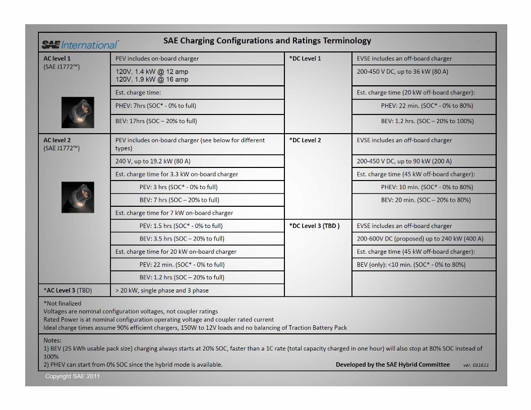
AC Level 1 120 V
Voltage [RMS] Max current [RMS]
16 A
AC Level 2 240 V 32 A (2001)80 A (2009)
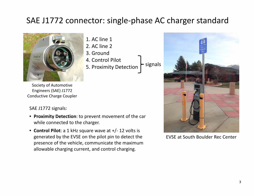
SAE J1772 connector: single‐phase AC charger standard
3
Society of Automotive Engineers (SAE) J1772
Conductive Charge Coupler
SAE J1772 signals:
• Proximity Detection: to prevent movement of the car while connected to the charger.
• Control Pilot: a 1 kHz square wave at +/‐ 12 volts is generated by the EVSE on the pilot pin to detect the presence of the vehicle, communicate the maximum allowable charging current, and control charging.
EVSE at South Boulder Rec Center
1. AC line 12. AC line 23. Ground4. Control Pilot5. Proximity Detection signals

J1772 signaling circuit
4
CP
PE
PP

Charging standards: DC [under development]
5
Battery system
+Vbat_
ACpowergrid
Electric Vehicle Supply
Equipment (EVSE)Charger
DC
signals
Ichg
Vehicle
connector

DC charging: standards under development
6
SAE J1772 "combo“ connector
CHAdeMO Associationup to 500V DC, up to 125 A
DC Level 1 200‐450 V
Voltage [DC] Max current [DC]
DC Level 2 200‐450 V
80 A
200 A
DC Level 3 200‐600 V 400 A
Nissan LEAF charging portsDC CHAdeMO (left) and AC J1772 (right)
7

Tesla (Proprietary)
8
• Mobile charger: 120 V – 240 V, up to 40 A• High power wall charger: 208 V ‐ 240 V, single phase, up to 70 A• Supercharger: 480 V DC, 250 A (up to 120 kW)• Battery swap: “full charge in 90 seconds”

Charger Implementation
9
Battery system
Charger+
Vbat_
ACpowergrid
Electric Vehicle Supply
Equipment (EVSE)
AC
signals signals
Ichg
Vehicle
vac(t)
iac(t)
+Vbat_
Ichg
AC‐DC rectifier
DC‐DC converter
Charger
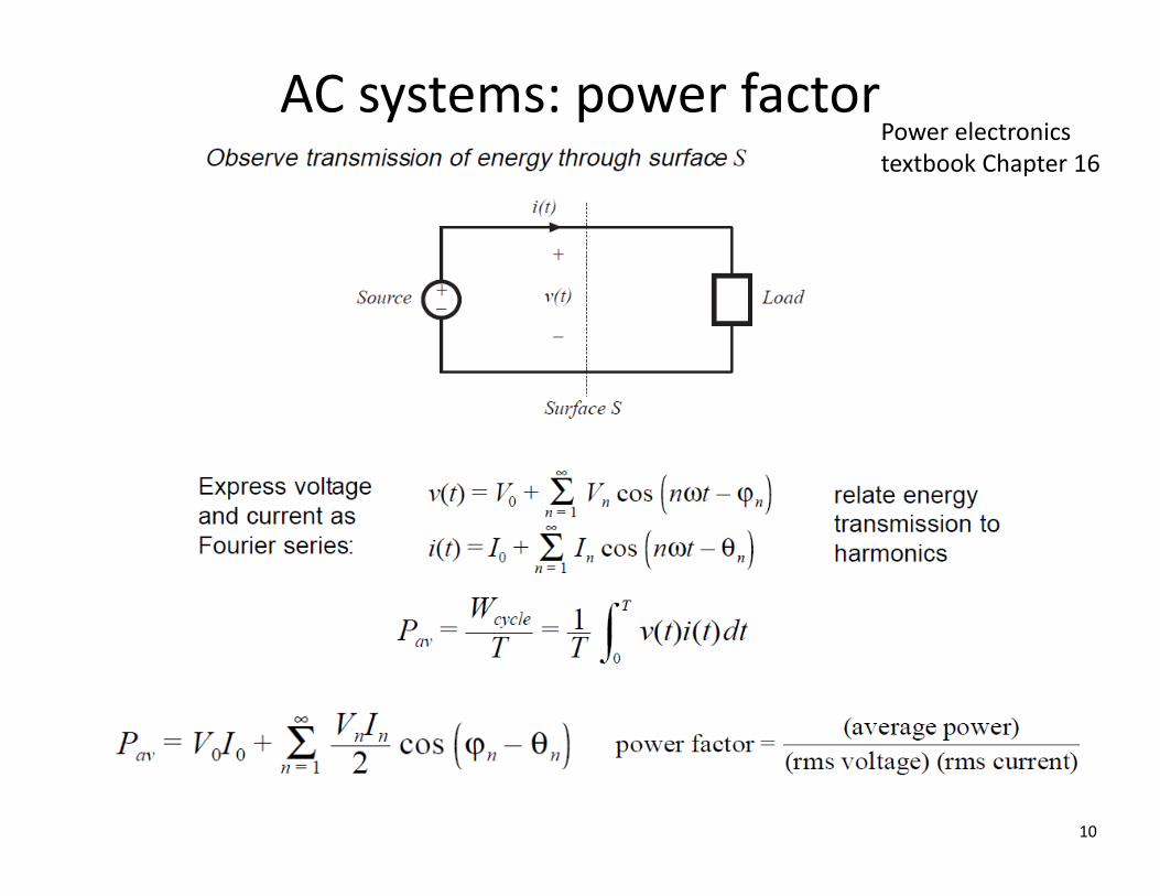
AC systems: power factor
10
Power electronics textbook Chapter 16
11

12

13

Conventional “peak‐detection” rectifier
Power factor = P
Vrms Irms
is very low (0.55)

Maximum power obtainable from 120V, 15A outlet (AC Level 1)

Charger implementation
16
Power electronics textbook, Chapter 18, PWM rectifiers

Ideal lossless rectifier
17
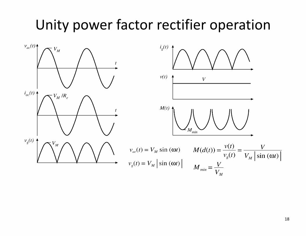
Unity power factor rectifier operation
18
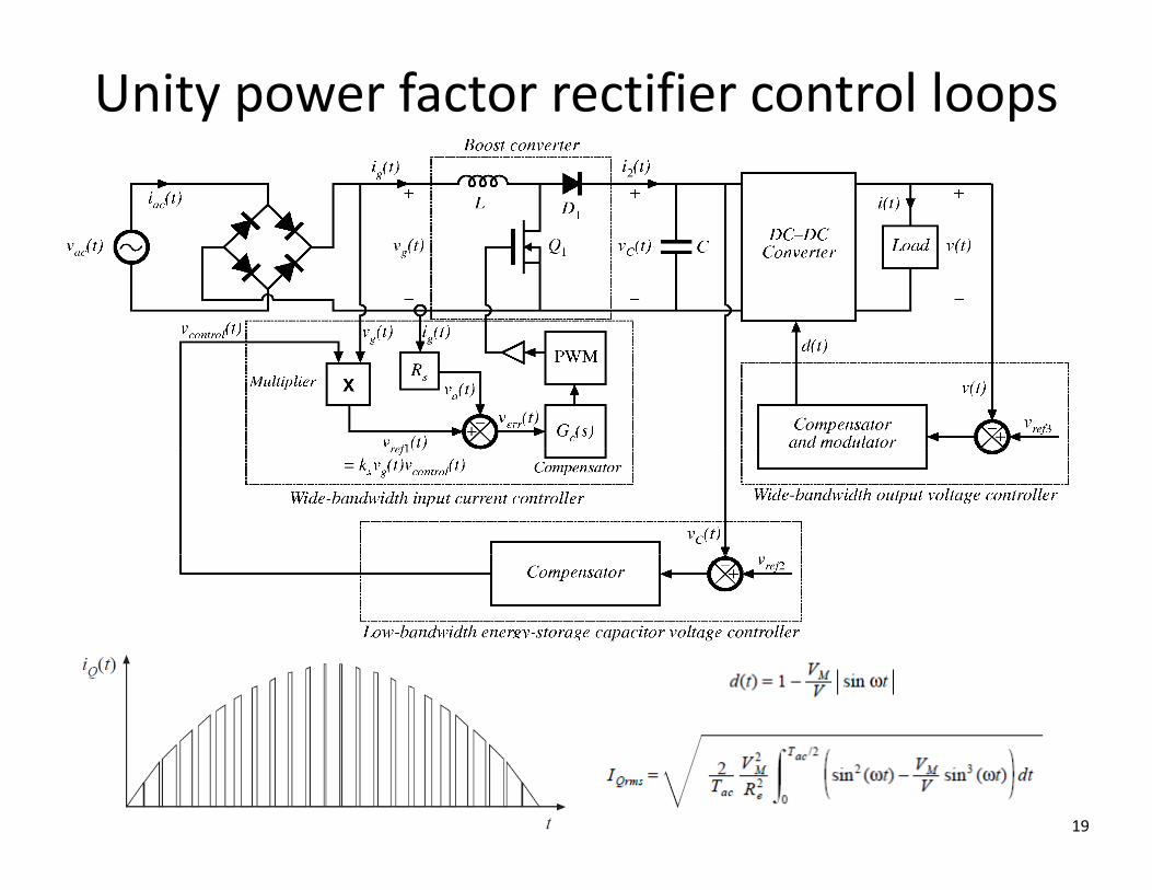
Unity power factor rectifier control loops
19
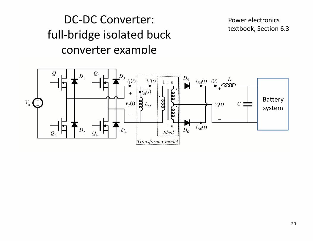
Power electronics textbook, Section 6.3
DC‐DC Converter: full‐bridge isolated buck
converter example
Batterysystem
20
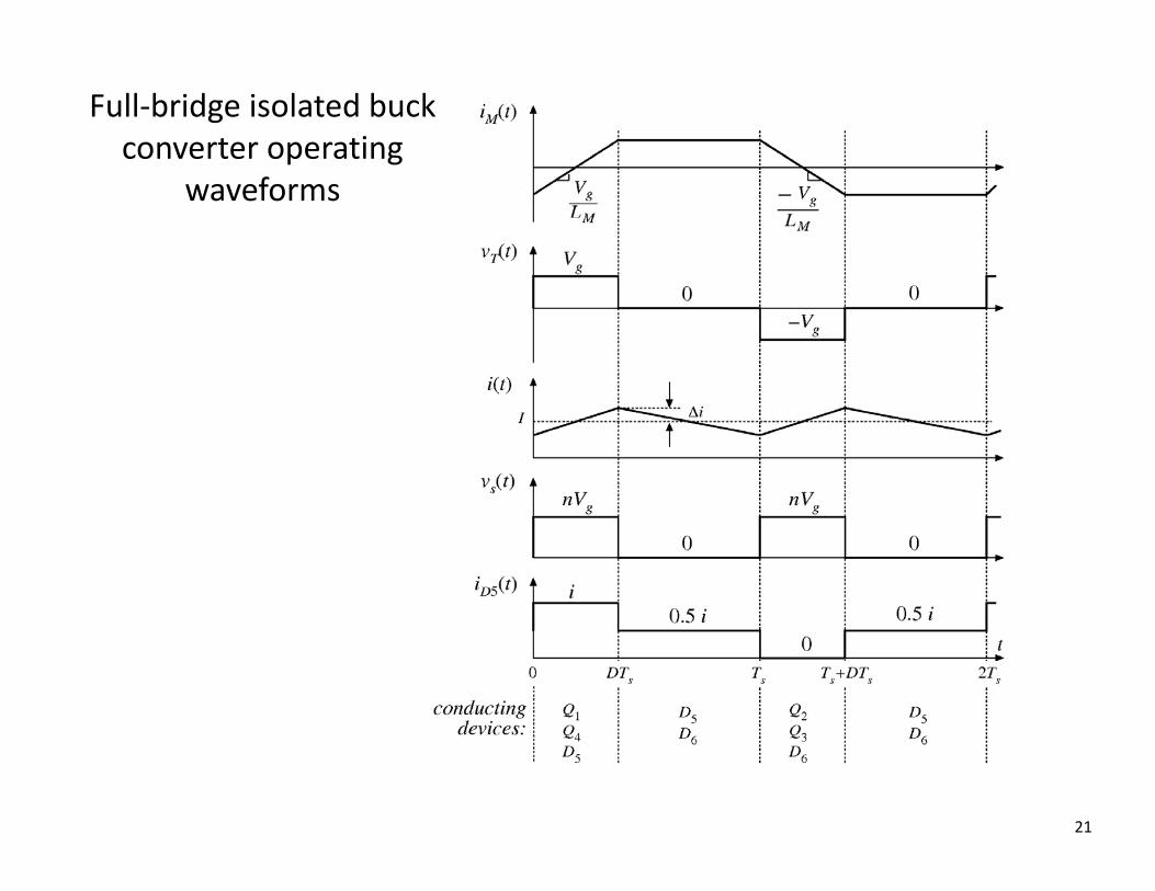
Full‐bridge isolated buck converter operating
waveforms
21
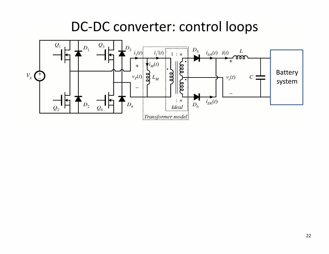
Batterysystem
DC‐DC converter: control loops
22

Research and development directions
23
• Fast DC chargers
• Charge management• Minimize cost
• Utilize excess generation from renewables
• Minimize stress on electric power distribution
• Minimize impact on battery life
• Vehicle‐to‐grid V2G concepts
• Inductive (wireless) charging
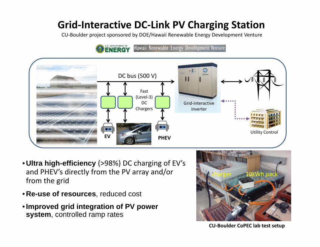
Grid‐Interactive DC‐Link PV Charging StationCU‐Boulder project sponsored by DOE/Hawaii Renewable Energy Development Venture
• Ultra high-efficiency (>98%) DC charging of EV’s and PHEV’s directly from the PV array and/or from the grid
• Re-use of resources, reduced cost
• Improved grid integration of PV power system, controlled ramp rates
EVUtility Control
PHEV
Grid‐interactive inverter
Fast (Level‐3)
DC Chargers
10kWh packcharger
CU‐Boulder CoPEC lab test setup
DC bus (500 V)
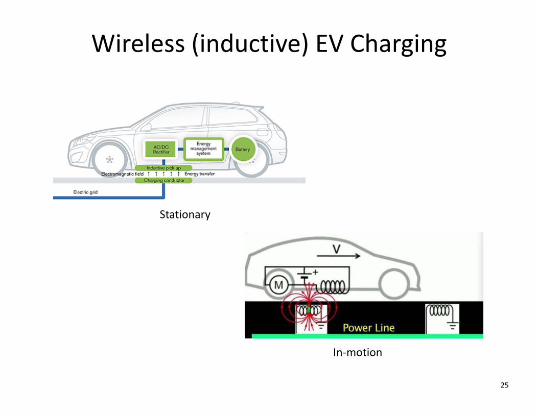
Wireless (inductive) EV Charging
25
Stationary
In‐motion
Related Documents