1 9 5/8” - 32.3 - 58 # TYPICAL COMPLETION SCHEMATIC 1 2 INTRODUCTION 2-4 3 SAFETY VALVE LANDING NIPPLE 5 4 SEPARATION SLEEVE 5 5 SURFACE CONTROLLED SUB SURFACE SAFETY VALVES (SSSV) 6 6 ACT TUBING RETRIEVABLE SAFETY VALVE 7 7 LANDING NIPPLES AND LOCK MANDRELS 8-10 8 ACT ‘RPT’ NO-GO LANDING NIPPLE AND LOCK MANDREL 11-12 9 ACT MODEL ‘F’ NIPPLE 13 10 ACT MODEL ‘R’ NIPPLE 14 11 ACT MODEL ‘PCMD’ AND ‘PCMU’ SLIDING SLEEVE 15 12 ACT MODEL ‘L ’ SLIDING SLEEVE 16 13 RUNNING / PULLING TOOLS 17-18 14 ACT MODEL ‘G’ BOTTOM BYPASS BLANKING PLUGS 19-20 15 ACT MODEL ‘FB-2’ AND ‘RB-2’ EQUALIZING CHECK VALVES 21-22 16 ACT MODEL ‘FGK’ EQUALIZING CHECK VALVE CHOKE WITH CERAMIC BEAN 23 17 ACT MODEL ‘LGE’ SEPARATION SLEEVE 24 18 ACT MODEL ‘LGK’ EQUALIZING CHECK VALVE CHOKE WITH CERAMIC BEAN 25 19 ACT MODEL ‘LGU’ BYPASS CHOKE 26 20 ACT MODEL ‘B’ DOWNHOLE INSTRUMENT HANGERS 27-28 21 BRIDGE PLUGS, CEMENT RETAINERS 29 22 PACKERS, EXPANSION JOINTS, ANCHOR LATCH 30 23 INJECTION PRESSURE OPERATED GAS LIFT VALVE 31-32 24 SIDE POCKET MANDREL 33-34 25 LATCHES 35 26 HD-TP / HD-TMP POSITIONING TOOLS 36 27 SLIP LOCK ASSEMBLY 37 28 SURGE TOOL ASSEMBLY 37 29 ACT TUBING PACK-OFF ANCHOR ASSEMBLY 38 30 TERMS AND CONDITIONS 39 PRODUCT LIST PAGE SR. NO. INDEX

Welcome message from author
This document is posted to help you gain knowledge. Please leave a comment to let me know what you think about it! Share it to your friends and learn new things together.
Transcript

1 9 5/8” - 32.3 - 58 # TYPICAL COMPLETION SCHEMATIC 1
2 INTRODUCTION 2-4
3 SAFETY VALVE LANDING NIPPLE 5
4 SEPARATION SLEEVE 5
5 SURFACE CONTROLLED SUB SURFACE SAFETY VALVES (SSSV) 6
6 ACT TUBING RETRIEVABLE SAFETY VALVE 7
7 LANDING NIPPLES AND LOCK MANDRELS 8-10
8 ACT ‘RPT’ NO-GO LANDING NIPPLE AND LOCK MANDREL 11-12
9 ACT MODEL ‘F’ NIPPLE 13
10 ACT MODEL ‘R’ NIPPLE 14
11 ACT MODEL ‘PCMD’ AND ‘PCMU’ SLIDING SLEEVE 15
12 ACT MODEL ‘L’ SLIDING SLEEVE 16
13 RUNNING / PULLING TOOLS 17-18
14 ACT MODEL ‘G’ BOTTOM BYPASS BLANKING PLUGS 19-20
15 ACT MODEL ‘FB-2’ AND ‘RB-2’ EQUALIZING CHECK VALVES 21-22
16 ACT MODEL ‘FGK’ EQUALIZING CHECK VALVE CHOKE
WITH CERAMIC BEAN 23
17 ACT MODEL ‘LGE’ SEPARATION SLEEVE 24
18 ACT MODEL ‘LGK’ EQUALIZING CHECK VALVE CHOKE
WITH CERAMIC BEAN 25
19 ACT MODEL ‘LGU’ BYPASS CHOKE 26
20 ACT MODEL ‘B’ DOWNHOLE INSTRUMENT HANGERS 27-28
21 BRIDGE PLUGS, CEMENT RETAINERS 29
22 PACKERS, EXPANSION JOINTS, ANCHOR LATCH 30
23 INJECTION PRESSURE OPERATED GAS LIFT VALVE 31-32
24 SIDE POCKET MANDREL 33-34
25 LATCHES 35
26 HD-TP / HD-TMP POSITIONING TOOLS 36
27 SLIP LOCK ASSEMBLY 37
28 SURGE TOOL ASSEMBLY 37
29 ACT TUBING PACK-OFF ANCHOR ASSEMBLY 38
30 TERMS AND CONDITIONS 39
PRODUCT LIST PAGESR.NO.
INDEX
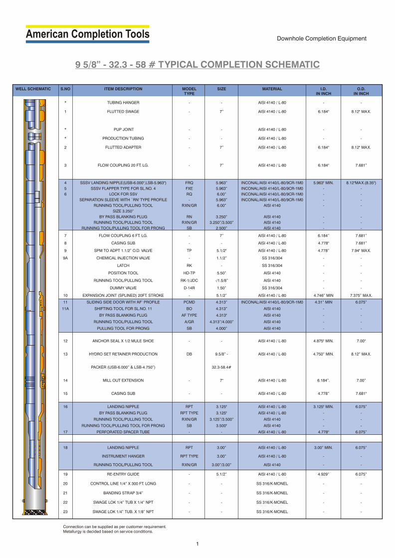
9 5/8” - 32.3 - 58 # TYPICAL COMPLETION SCHEMATIC
1
Downhole Completion Equipment
WELL SCHEMATIC S.NO ITEM DESCRIPTION MODEL SIZE MATERIAL I.D. O.D. TYPE IN INCH IN INCH
* TUBING HANGER - - AISI 4140 / L-80 - -
1 FLUTTED SWAGE - 7” AISI 4140 / L-80 6.184" 8.12" MAX.
* PUP JOINT - - AISI 4140 / L-80 - -
* PRODUCTION TUBING - - AISI 4140 / L-80 - -
2 FLUTTED ADAPTER - 7” AISI 4140 / L-80 6.184" 8.12" MAX.
3 FLOW COUPLING 20 FT. LG. - 7” AISI 4140 / L-80 6.184" 7.681”
4 SSSV LANDING NIPPLE(USB-6.000",LSB-5.963") FRQ 5.963” INCONAL/AISI 4140/L-80/9CR-1M0 5.963" MIN. 8.12"MAX.(8.35")
5 SSSV FLAPPER TYPE FOR SL.NO. 4 FXE 5.963” INCONAL/AISI 4140/L-80/9CR-1M0 - -
6 LOCK FOR SSV RQ 6.00” INCONAL/AISI 4140/L-80/9CR-1M0 - -
SEPARATION SLEEVE WITH `RN' TYPE PROFILE - 5.963” INCONAL/AISI 4140/L-80/9CR-1M0 - -
RUNNING TOOL/PULLING TOOL RXN/GR 6.00” AISI 4140 - -
SIZE 3.250”
BY PASS BLANKING PLUG RN 3.250” AISI 4140 - -
RUNNING TOOL/PULLING TOOL RXN/GR 3.250”/3.500” AISI 4140 - -
RUNNING TOOL/PULLING TOOL FOR PRONG SB 2.500” AISI 4140 - -
7 FLOW COUPLING 6 FT. LG. - 7” AISI 4140 / L-80 6.184” 7.681”
8 CASING SUB - - AISI 4140 / L-80 4.778" 7.681”
9 SPM TO ADPT 1.1/2” O.D. VALVE TP 5.1/2" AISI 4140 / L-80 4.778” 7.94" MAX.
9A CHEMICAL INJECTION VALVE - 1.1/2” SS 316/304 - -
LATCH RK - SS 316/304 - -
POSITION TOOL HD-TP 5.50” AISI 4140 - -
RUNNING TOOL/PULLING TOOL RK-1/JDC -/1.5/8” AISI 4140 - -
DUMMY VALVE D-14R 1.50” SS 316/304 - -
10 EXPANSION JOINT (SPLINED) 20FT. STROKE - 5.1/2” AISI 4140 / L-80 4.746” MIN 7.375” MAX.
11 SLIDING SIDE DOOR WITH ‘AF’ PROFILE PCMD 4.313” INCONAL/AISI 4140/L-80/9CR-1M0 4.31” MIN 6.075”
11A SHIFTING TOOL FOR SL.NO. 11 BO 4.313” AISI 4140 - -
BY PASS BLANKING PLUG AF TYPE 4.313" AISI 4140 - -
RUNNING TOOL/PULLING TOOL A/GR 4.313”/4.000” AISI 4140 - -
PULLING TOOL FOR PRONG SB 4.000” AISI 4140 - -
12 ANCHOR SEAL X 1/2 MULE SHOE - - AISI 4140 / L-80 4.875" MIN. 7.00"
13 HYDRO SET RETAINER PRODUCTION DB 9.5/8” - AISI 4140 / L-80 4.750” MIN. 8.12” MAX.
PACKER (USB-6.000” & LSB-4.750”) 32.3-58.4#
14 MILL OUT EXTENSION - 7" AISI 4140 / L-80 6.184”. 7.00”
15 CASING SUB - - AISI 4140 / L-80 4.778” 7.681"
16 LANDING NIPPLE RPT 3.125" AISI 4140 / L-80 3.125" MIN. 6.075”
BY PASS BLANKING PLUG RPT TYPE 3.125" AISI 4140 / L-80 - -
RUNNING TOOL/PULLING TOOL RXN/GR 3.125”/3.500” AISI 4140 - -
RUNNING TOOL/PULLING TOOL FOR PRONG SB 3.500" AISI 4140 - -
17 PERFORATED SPACER TUBE - - AISI 4140 / L-80 4.778" 6.075”
18 LANDING NIPPLE RPT 3.00” AISI 4140 / L-80 3.00” MIN. 6.075”
INSTRUMENT HANGER RPT TYPE 3.00” AISI 4140 / L-80 - -
RUNNING TOOL/PULLING TOOL RXN/GR 3.00”/3.00” AISI 4140 - -
19 RE-ENTRY GUIDE - 5.1/2” AISI 4140 / L-80 4.929” 6.075”
20 CONTROL LINE 1/4” X 300 FT. LONG - - SS 316/K-MONEL - -
21 BANDING STRAP 3/4” - - SS 316/K-MONEL - -
22 SWAGE LOK 1/4” TUB X 1/4” NPT - - SS 316/K-MONEL - -
23 SWAGE LOK 1/4” TUB. X 1/8” NPT - - SS 316/K-MONEL - -
Connection can be supplied as per customer requirement.Metallurgy is decided based on service conditions.

WELL COMPLETION:The well is the communication channel joining the reservoir for the development of Oil & Gas Fields. It influences cost and economics of exploitation of the reservoir. Therefore, every ef fort should be made for optimum well design.
The configuration of a well af ter completion can be seen as a number of conduits, Tubular or Annular isolated from each other by seals at surface and subsurface with provisions for selective inter-communication and safety shutof f.
The flow conduits are Casing & Tubing. Tubing size selection requires evaluation of pressure losses in vertical flow.
In Gas Well erosion velocity is of ten critical.
COMPLETION METHODS: There are three basic methods to complete a well. Open HoleCased or perforated holeLiner Completion
! In open hole, casing is set only to the top of or slightly into the Completion interval.! In cased hole and perforated completion, casing is set into or through the production formation and cemented.! In a liner completion, casing is run to the top of the pay zone and a liner is set across the producing formation.
TUBING AND CASING CONFIGURATIONS: Several configuration are applicable to the completion methods.
TUBINGLESS COMPLETION: This is the most simple tubular arrangement and may be used in high rate oil & gas wells, where pressures and corrosive fluids are not detrimental to the casing.
TUBING AND PACKER CONFIGURATIONS: Well completion with Packer permit a number of configurations. Packers are run to isolate the casing from corrosive fluids and or high pressure.! To stabilize and control flow from pay zones.! In conjunction with artificial lif t system.! To selectively' produce multiple zones.! Selective stimulation becomes feasible.! Wireline and downhole operations become feasible.
ANNULUS/TUBING SEALS: Apart from Tubing Head, Tubing Connections, sealing between annulus and tubing rests with packer and other equipment, such as, Anchor Seals, Locator Seals, Telescopic Joint, Tubing Seal receptacles and Sliding Sleeves.
CIRCULATION AND COMMUNICATION DEVICES: These are needed to establish Tubing annulus communication, in order to equalize pressures and circulate fluid. These devices are Sliding Sleeves, Side Pocket Mandrels and Ported Nipples.
SAFETY VALVES: Safety Valve provides final control of the well, when other controls have ceased to function.
INTRODUCTION
2
Well Completion

Downhole Completion Equipment
3
ACT of fers full set of downhole well completion strings with all equipment like:
1. Standard hardware items like Fluted Swage, Adapters, Flow Coupling, Blast Joint, Cross Overs, Perforated
Joints, Wireline Re-entry Guide, Pump Out Plug etc.,
2. Safety Valve Systems both Tubing and Wireline Retrievable type with all required accessories, tools and
wireline operating tools,
3. Expansion joints,
4. Side Pocket Mandrels with all accessories, tools, wireline tools including Gas Lif t and chemical injection
requirements,
5. Sliding Sleeves with all tools, accessories and wireline tools,
6. All types of Packers Permanent & Retrievable Mechanical, Hydraulic, Wireline set ting options with all
accessories and set ting tools like all types of set ting tolls, Locator Anchor Seal assembly with dif ferent type of
seal systems for Permanent Packers, Pump Out Plug, Mill Out Extension, Seal Bore Extension, Packer Milling
and Retrieving Tools,
7. Polished Bore Receptacles, accessories, tools,
8. Landing Nipples both ported (for safety valves) and non-ported with all accessories and tools like Blanking
Plugs, Instrument Hangers, with all accessories, tools and wireline tools,
9. All completion accessories like control lines, Banding Strap, Banding Buckles etc.
ACT manufactures and supplies all items under relevant API licenses, in all size, types, lengths, materials and are
available for standard and sour services, dif ferent pressure and temp. ranges with API and all types of Premium thread
connections cut by their authorized licensees, .
ACT has the capability to design and supply completion equipment as per customer's requirement.
FLUTED SWAGE & FLUTED ADAPTERS:
The Fluted Swage and Fluted Adapter are customer specified threaded adapters of short lengths which are run well
completion strings near the top to centralize the string in the well. They have ID matching to string ID and are made with
fluted design to allow fluid circulation in the well.
FLOW COUPLING & BLAST JOINT:
Flow Coupling and Blast Joints are thick walled tubular components normally utilized in well completions and located
near the changes in tubing ID or against the well perforations. The items are provided with a thicker wall to avoid wear
and tear due to erosion caused by fluid turbulence or corrosion and avoid failure.
Normally they have connection OD and tubing string ID.
ACT Flow Couplings are normally available in 2', 4', 6', 8', 10', 20' or any customer specified lengths and connections
and the ACT Blast Joints are available in 10' or 20' or any customer specified lengths and connections.
CROSS OVERS:
The Cross Over is used in the well completion string to connect dif ferent type, size or thread connection completion
items and are very important and essential item.
TUBING PUP JOINTS:
The Tubing Pup Joint is a short piece of tubing in any required length and is used in the completion string at any
required depth between dif ferent items to adjust length and space out items.
PERFORATED JOINT:
The Perforated Joint is a Tubing Pup Joint with specific flow conduit holes made for fluid entry and flow and is used in
the Completion String between the Nipples and facilitates well flowing pressure and temp. measurement or acquisition
of downhole production data while the well is flowing.
INTRODUCTION

LANDING NIPPLES:
Landing nipples are profiled subs typically run above and / or below retrievable or permanent packers, providing a
method of placing various flow control devices in the completion string.
Landing nipples feature an internal seal bore and profile to accept a locking device to anchor flow control accessories.
Seal bores and lock profiles are machined to match a variety of connection systems and are available full-opening, or
slightly restricted with a no-go feature to provide a positive stop for a flow control device.
Landing nipples are sized to match any tubing sizes, while seal bore sizes are available to match a variety of weights
and connection systems. Most type, size, material, API or premium thread connections are available.
ACT provides most common landing nipple profiles like X, R. XN, RN, F, R, RPT etc. and many others on customer
request.
SLIDING SLEEVE:
A completion device that can be operated to provide a flow path between the production conduit and the annulus.
Sliding sleeves incorporate a system of ports that can be opened or closed by a sliding component that is generally
controlled and operated by slickline tool string. These are manufactured elastometric for low pressure and non-
elastometric for high pressure.
EXPANSION JOINT / TRAVEL JOINT:
The Expansion Joints are designed to be used in single and dual - string completion to accommodate changes in
tubing length caused by variations in pressure, temperature or both. They are capable of maintaining the pressure
integrity of tubing while allowing the string to safely expand and contract. The Expansion Joint can be run above
Packers. The proper placement and stroke selection of these splined slip joints reduce the chances of over stressing
the well tubing during production, acidizing, fracturing and other well operations. Alloy-steel construction gives these
joints high body and end-connection tensile strength. Stroke length may be changed in the field. The splines transmit
torque through the joint.
The travel joint consists of a top sub, outer mandrel, inner mandrel and shear sleeve. The packing stack is retained by
the retainer cap. An o-ring is installed in the top sub. Sheer pins hold the travel joint in the fully extended, closed or
partially open condition and at 1’ interval. The travel length of the joints can be 10’ or 20’.
ANCHOR LOCATOR SEAL ASSEMBLY:
Anchor Seal Assemblies anchor into the Packer top and seal in the bore of the Packer or Seal Bore Extension below the
Packer. The Anchor Seal Assembly transfers tubing forces through the anchor into the packer, the seals are static and
are only subjected to pressure dif ferentials.
PUMP-OUT-PLUG:
The Pump Out Plug temporarily seals the bottom of the tubing string to prevent fluid from moving up the tubing while
tripping in the hole. The Pump Out Ball Seat can be used as a bridging device to set a hydraulic packer or to
hydraulically test the tubing string; the ball seat allows the tubing to fill with fluid while running in the hole. Af ter the
specific work requirement is met the, the ball can be pumped out with over pressuring the string fluid and provides a full
bore flow.
WIRELINE RE-ENTRY GUIDE:
The Wireline Re-Entry Guide is used for safe re-entry of wireline tools from casing into the tubing string. Threaded on
top end only, it is at tached to the bottom end of the production string and may be designed to plain end or bevel end,
tapered, fluted, half or full mule shoe preparation with a full open internal diameter.
INTRODUCTION
4
Downhole Completion Equipment

Landing Nipple * Working
Tubing Size Seal bore Pressure
in. mm. in. mm. psi
2 3/8 60.33 1.710 43.43
1.875 47.63
2.125 53.98
2 7/8 73.03 2.188 55.58
2.313 58.75
2.562 65.07
3 ½ 88.90 2.750 69.85 5,000
2.813 71.45 6,000
4 101.60 3.313 84.15 7,500
3.437 87.30 10,000
4 ½ 114.30 3.688 93.68
3.813 96.85
5 127.00 4.125 104.78
5 ½ 139.70 4.562 115.87
5.750 146.05
7 177.80 5.875 149.23
5.963 151.46
Safety Valve Landing Nipples are used to accommodate ACT model wireline
retrievable sub surface safety valves. These nipples have a locking recess and a
hydraulic communication port located between the two polished bores. This
nipple features an integral control line connection port which operates Sub
Surface Safety Valve.
SAFETY VALVE LANDING NIPPLE
FLAPPER-TYPE WIRELINE-RETRIEVABLE SAFETY VALVES
SAFETY VALVE LANDING NIPPLE
Downhole Flow Control
5
* Please check with factory for the metallurgy & pressure rating
ACT Separation Sleeve, when at tached to an appropriate lock is a wireline
Retrievable Tool, used to isolate the control line port of Safety Valve Landing
Nipples.
SEPARATION SLEEVE
SEPARATION SLEEVE
Landing Nipple * Working
Tubing Size Seal bore Valve ID Pressure
in. mm. in. mm. in. mm. psi
2 3/8 60.33 1.710 43.43 0.62 15.75
1.875 47.63 0.75 19.05
2.125 53.98 0.81 20.57
2 7/8 73.03 2.188 55.58 0.81 20.57
2.313 58.75 1.12 28.45
2.562 65.07 1.00 25.40
3 ½ 88.90 2.750 69.85 1.50 38.10 5,000
2.813 71.45 1.50 38.10 6,000
4 101.60 3.313 84.15 1.75 44.45 7,500
3.437 87.30 1.75 44.45 10,000
4 ½ 114.30 3.688 93.68 1.87 47.50
3.813 96.85 2.12 53.85
5 127.00 4.125 104.78 2.38 57.15
5 ½ 139.70 4.562 115.87 2.56 65.02
5.750 146.05 3.38 85.85
7 177.80 5.875 149.23 3.50 88.90
5.963 151.46 3.50 88.90
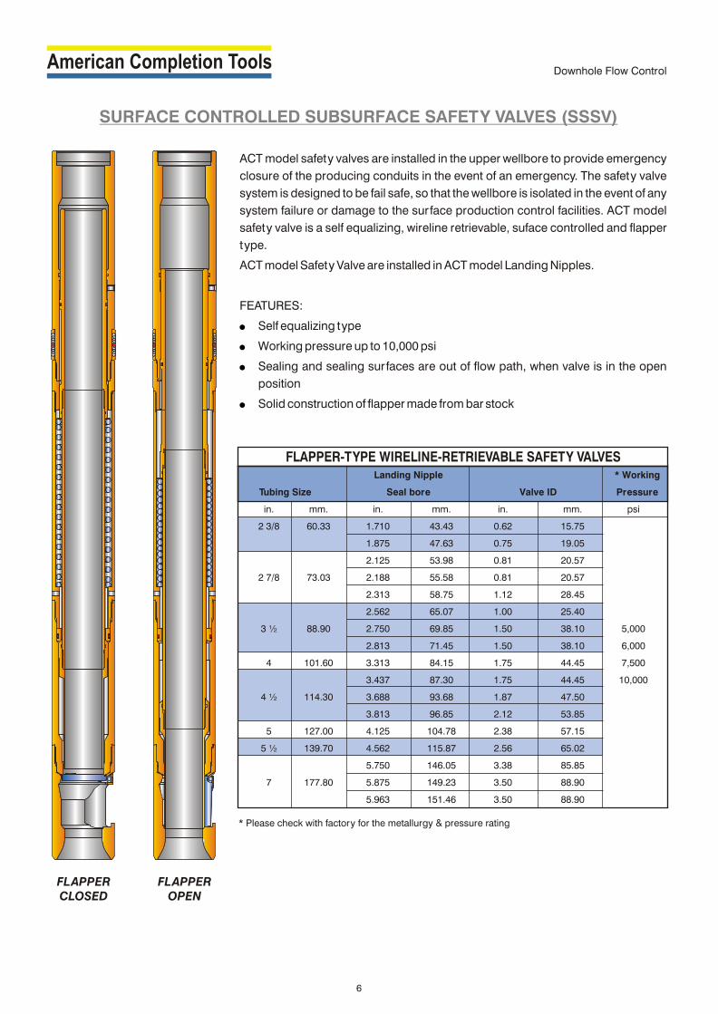
ACT model safety valves are installed in the upper wellbore to provide emergency
closure of the producing conduits in the event of an emergency. The safety valve
system is designed to be fail safe, so that the wellbore is isolated in the event of any
system failure or damage to the surface production control facilities. ACT model
safety valve is a self equalizing, wireline retrievable, suface controlled and flapper
type.
ACT model Safety Valve are installed in ACT model Landing Nipples.
FEATURES:
Self equalizing type
Working pressure up to 10,000 psi
Sealing and sealing surfaces are out of flow path, when valve is in the open
position
Solid construction of flapper made from bar stock
!
!
!
!
SURFACE CONTROLLED SUBSURFACE SAFETY VALVES (SSSV)
FLAPPER-TYPE WIRELINE-RETRIEVABLE SAFETY VALVES
FLAPPER CLOSED
FLAPPER OPEN
6
* Please check with factory for the metallurgy & pressure rating
Downhole Flow Control

Tubing Retrievable Surface Controlled Sub Surface Safety Valves are made up to and from a part
of production string. Hydraulic control line extending from the valve to the Wellhead connects to a
part on the outside of the valve. The opposite end of the control line connects to the Wellhead.
Hydraulic pressure applied through this control line acts on hydraulic pistons within the valve. The
force generated moves the flow tube down against a power spring and tubing pressure, causing
the flapper to open. Maintaining this hydraulic pressure allows unrestricted well production
through the valve. Releasing the hydraulic pressure causes the flow tube to move up by the action
of the power spring, thus allowing the flapper to the closed position.
ACT TUBING RETRIEVABLE SAFETY VALVE
TUBING RETRIEVABLE SAFETY VALVES
TUBING SIZE Max. OD Min. ID WORKING PRESSURE
(in. [mm]) (in. [mm]) (in. [mm]) psi
2.875 [73.0] 5.453 [138.5] 2.224 [56.9]
3.500 [88.9] 5.750 [146.1] 2.625 [66.8] 5,000 / 10,000
4.500 x 3.500 [114.3 x 88.9] 5.945 151.0] 2.562 [65.0]
4.500 [114.3] 7.875 [200.0] 3.812 [96.8]
5.500 [139.7] 8.375 [212.7] 4.562 [115.9] 5,000
7.000 [177.8] 9.437 [239.7] 6.000 [152.4]
TUBING RETRIEVABLE SAFETY VALVE
7
Downhole Flow Control

ACT X and R Landing Nipples and Lock Mandrels
ACT X and R landing nipples are run into the well on the
completion tubing to provide a specific landing location
for subsurface flow control equipment. The common
internal profiles of these landing nipples make them
universal. The ACT X landing nipple is used in standard
weight tubing. The ACT R landing nipple is typically used
with heavyweight tubing.
The completion can have as many selective nipples with
the same ID in any sequence as desired on the tubing
string. This versatility results in an unlimited number of
positions for set ting and locking subsurface flow
controls. The flow control, which is at tached to the
required ACT X or R lock mandrel, is run in the well via the
selective running tool on slickline.
The slickline operator using the selective running tool
can set the flow control in any one of the landing nipples
at the desired depth. If this location is unsatisfactory or if
well conditions change, the flow control may be moved
up or down the tubing string to another nipple location.
These operations can be done by slickline under
pressure without killing the well.
ACT XN and RN No-Go Landing Nipples and Lock
Mandrels
This equipment is designed for use in single nipple
installations or as the bottom nipple in a series of ACT X
or R landing nipples. These landing nipples have the
same packing bore ID for a particular tubing size and
weight. ACT X and XN landing nipples are designed for
use with standard weight tubing. ACT R and RN landing
nipples are designed for use with heavy weight tubing.
(The N designates no-go nipples.)
Applications
LANDING NIPPLES AND LOCK MANDRELS
"X " LANDING NIPPLE AND LOCK MANDREL
"R" LANDING NIPPLE AND LOCK MANDREL
8
Downhole Flow Control

LANDING NIPPLES AND LOCK MANDRELS
!
!
!
!
!
!
!
!
!
!
!
!
!
!
!
!
!
!
!
!
!
!
Gauge hangers for bottomhole pressure/temperature
surveys
Positive locator for straddle systems
Plugging under pressure
Almost unlimited locations for set ting and locking
subsurface flow controls
Features
Landing nipples
Large bore for minimum restriction
Universal nipple with one internal profile
Lock Mandrels
Retractable locking keys
Locks designed to hold pressure from above or
below from sudden reversals
Optional holddown
Interference holddown for smaller locks
Shear pin holddown for larger locks
Benefits
Landing nipples
Versatility helps reduce completion and production
maintenance costs
Simple operation
Multiple options when running, set ting or retrieving
subsurface flow controls
Lock mandrels
Faster slickline service because of the retractable
keys
Operator control of locating, landing and locking in
the selected nipple
Inside fishing neck provides large ID to maximize
production
Optional holddown feature for high flow rates safety
valves installations
"XN" NO-GO LANDING NIPPLE AND LOCK MANDREL
"RN" NO-GO LANDING NIPPLE AND LOCK MANDREL
9
Downhole Flow Control

‘X’ AND ‘XN’ LANDING NIPPLES AND LOCK MANDRELS FOR STANDARD TUBING WEIGHTS
TUBING X PROFILE XN PROFILE LOCKPACKING PACKING NO-GO MANDREL
SIZE WEIGHT ID DRIFT BORE BORE ID ID(in.) (mm) lb/f t (kg/m) (in.) (mm) (in.) (mm) (in.) (mm) (in.) (mm) (in.) (mm) (in.) (mm)
1.050 26.67 1.20 1.79 0.824 20.93 0.730 18.54 AVAILABLE ON REQUEST1.315 33.40 1.80 2.68 1.049 26.64 0.955 24.261.660 42.16 2.30 3.43 1.380 35.05 1.286 32.66 1.250 31.75 1.250 31.75 1.135 28.83 0.62 15.75
2.40 3.57 1.380 35.05 1.286 32.66 1.250 31.75 1.250 31.75 1.135 28.83 0.62 15.752.40 3.57 1.660 42.16 1.516 38.51 1.500 38.10 1.500 38.10 1.448 36.78 0.75 19.05
1.900 48.26 2.76 4.11 1.610 40.89 1.516 38.51 1.500 38.10 1.500 38.10 1.448 36.78 0.75 19.052.90 4.32 1.610 40.89 1.516 38.51 1.500 38.10 1.500 38.10 1.448 36.78 0.75 19.05
2.063 52.40 3.25 4.84 1.751 44.48 1.657 42.09 1.625 41.28 1.625 41.28 1.536 39.01 0.75 19.052.375 60.33 4.60 6.85 1.995 50.67 1.901 48.29 1.875 47.63 1.875 47.63 1.791 45.49 1.00 25.40
4.70 7.00 1.995 50.67 1.901 48.29 1.875 47.63 1.875 47.63 1.791 45.49 1.00 25.402.875 73.03 6.40 9.53 2.441 62.00 2.347 59.61 2.313 58.75 2.313 58.75 2.205 56.01 1.38 35.05
6.50 9.68 2.441 62.00 2.347 59.61 2.313 58.75 2.313 58.75 2.205 56.01 1.38 35.053.500 88.90 9.30 13.85 2.992 76.00 2.867 72.82 2.813 71.45 2.813 71.45 2.666 67.72 1.75 44.45
10.30 15.34 2.992 74.22 2.797 71.04 2.750 69.85 2.750 69.85 2.635 66.93 1.75 44.454.000 101.60 11.00 16.38 3.476 89.29 3.351 85.12 3.313 84.15 3.313 84.15 3.135 79.63 2.12 53.854.500 114.30 12.75 18.99 3.958 100.53 3.833 97.36 3.813 96.85 3.813 96.85 3.725 94.62 2.62 66.555.000 127.00 13.00 19.36 4.494 114.15 4.369 110.97 4.313 109.55 4.313 109.55 3.987 101.27 2.62 66.555.500 139.70 17.00 25.32 4.892 124.26 4.767 121.08 4.562 115.87 4.562 115.87 4.455 113.16 3.12 79.25
‘R’ AND ‘RN’ LANDING NIPPLES AND LOCK MANDRELS FOR HEAVY TUBING WEIGHTS
TUBING R PROFILE RN PROFILE LOCKPACKING PACKING NO-GO MANDREL
SIZE WEIGHT ID DRIFT BORE BORE ID ID(in.) (mm) lb/f t (kg/m) (in.) (mm) (in.) (mm) (in.) (mm) (in.) (mm) (in.) (mm) (in.) (mm)
1.660 42.16 3.02 4.50 1.278 32.46 1.184 30.07 1.125 28.58 1.125 28.58 1.012 25.70 AVAILABLE ON REQUEST
1.900 48.26 3.64 5.42 1.500 38.10 1.406 35.71 1.375 34.93 1.375 34.93 1.250 31.75 0.62 15.755.30 7.89 1.939 49.25 1.845 46.86 1.781 45.24 1.781 45.24 1.640 41.66 0.88 22.35
2.375 60.33 5.95 8.86 1.867 47.42 1.773 45.03 1.710 43.43 1.710 43.43 1.560 39.62 0.75 19.056.20 9.23 1.853 47.07 1.759 44.68 1.710 43.43 1.710 43.43 1.560 39.62 0.75 19.057.70 11.47 1.703 43.26 1.609 40.87 1.500 38.10 1.500 38.10 1.345 34.16 0.62 15.757.90 11.77 2.323 59.00 2.229 56.62 2.199 55.58 2.188 55.58 2.010 51.05 1.12 28.458.70 12.96 2.259 57.38 2.165 54.99 2.125 53.98 2.125 53.98 1.937 49.20 0.88 22.358.90 13.26 2.243 56.97 2.149 54.58 2.125 53.98 2.125 53.98 1.937 49.20 0.88 22.35
2.857 73.03 9.50 14.15 2.196 55.75 2.101 53.37 2.000 50.80 2.000 50.80 1.881 47.78 0.88 22.3510.40 15.49 2.151 54.64 2.057 52.25 2.000 50.80 2.000 50.80 1.881 47.78 0.88 22.3511.00 16.38 2.065 52.45 1.971 50.06 1.875 47.63 1.875 47.63 1.716 43.59 0.88 22.3511.65 17.35 1.995 50.67 1.901 48.29 1.875 47.63 1.875 47.63 1.716 43.59 0.88 22.3512.95 19.29 2.750 69.85 2.625 66.68 2.562 65.07 2.562 65.07 2.329 59.16 1.38 35.05
3.500 89.90 15.80 23.53 2.548 64.72 2.423 61.54 2.313 58.75 2.313 58.75 2.131 54.13 1.12 28.4516.70 24.87 2.480 62.99 2.355 59.82 2.313 58.75 2.313 58.75 2.131 54.13 1.12 28.4517.05 25.40 2.440 61.98 2.315 58.80 2.188 55.58 2.188 55.58 2.010 51.05 1.12 28.45
4.000 101.60 11.60 17.28 3.428 87.07 3.303 83.90 3.250 82.55 3.250 82.55 3.088 78.44 1.94 49.2813.40 19.96 3.340 84.84 3.215 81.66 3.125 79.38 3.125 79.38 2.907 73.84 1.94 49.2812.75 18.99 3.958 100.53 3.833 97.36 3.813 96.85 3.813 96.85 3.725 94.62 2.12 53.8513.50 20.11 3.920 99.57 3.795 96.39 3.688 93.68 3.688 93.68 3.456 87.78 2.38 60.45
4.500 114.30 15.50 23.09 3.826 97.18 3.701 94.01 3.688 93.68 3.688 93.68 3.456 87.78 2.38 60.4516.90 25.17 3.754 95.35 3.629 92.18 3.437 87.30 3.437 87.30 3.260 82.80 1.94 49.2819.20 28.60 3.640 92.46 3.515 89.28 3.437 87.30 3.437 87.30 3.260 82.80 1.94 49.28
5.000 127.00 15.00 22.34 4.408 111.96 4.283 108.79 4.125 104.78 4.125 104.78 3.913 99.39 2.75 69.8518.00 26.81 4.276 108.61 4.151 105.44 4.000 101.60 4.000 101.60 3.748 95.20 2.38 60.4517.00 25.32 4.892 124.26 4.767 121.08 4.562 115.87 4.562 115.87 4.455 113.16 2.85 72.39
5.500 139.70 20.00 29.79 4.778 121.36 4.653 118.19 4.562 115.87 4.562 115.87 4.455 113.16 2.85 72.3923.00 34.26 4.670 118.62 4.545 115.44 4.313 109.55 4.313 109.55 3.987 101.27 2.62 66.55
6.000 152.40 15.00 22.34 5.524 140.31 5.399 137.13 5.250 133.35 5.250 133.35 5.020 127.51 3.50 88.9018.00 26.81 5.424 137.77 5.299 134.59 5.250 133.35 5.250 133.35 5.020 127.51 3.50 88.90
6.625 168.28 24.00 35.75 5.921 150.39 5.796 147.22 5.625 142.88 5.625 142.88 5.500 139.70 3.50 88.9028.00 41.71 5.791 147.09 5.666 143.92 5.625 142.88 5.625 142.88 5.500 139.70 3.50 88.9017.00 25.32 6.538 166.07 6.431 163.35 5.962 151.43 5.962 151.43 5.750 146.05 3.75 95.2520.00 29.79 6.456 163.98 6.331 160.81 5.962 151.43 5.962 151.43 5.750 146.05 3.75 95.2523.00 34.26 6.366 161.70 6.241 158.52 5.962 151.43 5.962 151.43 5.750 146.05 3.75 95.25
7.000 177.80 26.00 38.73 6.276 159.41 6.151 156.24 5.962 151.43 5.962 151.43 5.750 146.05 3.75 95.2529.00 43.20 6.184 157.07 6.059 153.90 5.962 151.43 5.962 151.43 5.750 146.05 3.75 95.2532.00 47.66 6.094 154.79 6.969 177.01 5.962 151.43 5.962 151.43 5.750 146.05 3.75 95.2535.00 52.13 6.004 152.50 5.879 149.33 5.875 149.23 5.875 149.23 5.750 146.05 3.75 95.2536.00 53.62 7.825 198.76 7.700 195.58 7.450 189.23 7.450 189.23 7.325 186.06 5.250 133.35
8.625 219.08 36.00 53.62 7.825 198.76 7.700 195.58 7.250 184.15 7.250 184.15 7.125 180.98 5.250 133.3536.00 53.62 7.825 198.76 7.700 195.58 7.050 179.07 7.050 179.07 6.925 175.90 5.250 133.35
10
Downhole Flow Control

ACT RPT no-go landing nipple system provides a mean of
running a series of positive location landing nipples in a
tubing string with minimum restriction. ACT RPT no-go
landing nipples are designed to accept ACT RPT lock
mandrels with a rated working pressure of 10,000 psi (690
bar) dif ferential and greater from above and below.
The ACT RPT no-go lock mandrel locates on top of the
nipples polished bore; therefore, there are no secondary
restrictions normally accosiated with bot tom no-go
profiles. This feature makes ACT RPT system well suited for
high pressure, high volume, large bore completions. ACT
RPT lock mandrels in any given size range are designed to
use the same running tool and pulling tool.
Features
Large bore
Lock mandrel locates on top of the nipples polished
bore
Landing nipples can accept ACT RPT lock mandrels
with a rated working pressure of 10,000 psi (690 bar)
dif ferential from above and below
A series of profile IDs are established for common tubing
strings by size and weight
!
!
!
!
ACT ‘RPT’ NO-GO LANDING NIPPLE AND LOCK MANDREL
"RPT" TYPE NO-GO LANDING NIPPLE AND LOCK MANDREL
11
Downhole Flow Control

‘RPT’ LANDING NIPPLES AND LOCK DIMENSIONS
NIPPLE PROFILE LOCK MANDREL
TUBING SIZE SEALBORE (MIN. ID) ID OD
in. mm in. mm in. mm in. mm
1.500 38.10 1.560 39.62
1.625 41.28 1.685 42.80
2 3/8 60.33 1.781 45.24 0.75 19.05 1.841 46.76
1.875 47.63 1.935 49.15
2.000 50.80 2.060 52.32
2.125 53.98 2.185 55.5
2.000 50.80 2.060 52.32
2.125 53.98 2.185 55.5
2 7/8 73.03 2.188 55.58 1.12 28.45 2.248 57.10
2.313 58.75 2.373 60.27
2.482 63.04 2.542 64.57
2.562 65.07 2.622 66.6
2.650 67.31 2.710 68.83
3 1/2 88.90 2.750 69.85 1.50 38.10 2.810 71.37
2.810 71.45 2.860 72.64
2.875 73.03 2.935 74.55
3.000 76.20 1.75 44.45 3.060 77.72
4 - 4 1/2 101.6 - 114.3 3.125 79.38 3.210 81.53
3.125 79.38 1.94 49.28 3.210 81.53
3.313 84.15 3.395 86.23
3.437 87.30 3.520 89.41
3.562 90.47 3.650 92.71
4 1/2 - 5 114.3 - 127 3.688 93.68 1.94 49.28 3.770* 95.76
3.750 95.25 3.807 96.70
3.813 96.85 3.895 98.93
4.000 101.60 4.090 103.89
4.188 106.38 4.270* 108.46
4.250 107.95 4.332* 110.03
4.313 109.55 4.395 111.63
4.437 112.70 2.75 69.85 4.520* 114.81
5 1/2 139.70 4.500 114.30 4.550 115.57
4.562 115.87 4.650 118.11
4.688 119.08 4.760* 120.90
4.688 119.08 4.760* 120.90
4.750 120.65 3.12 79.25 4.825 122.56
4.813 122.25 4.890 124.21
5.250 133.35 5.334 135.48
5.500 139.70 5.585 141.86
5.625 142.88 5.710 145.03
5.750 146.05 5.840* 148.34
7 177.80 5.813 147.65 3.68 93.47 5.890* 149.61
5.875 149.23 5.940 150.88
5.963 151.46 6.025 153.04
6.125 155.58 6.180 156.97
6.250 158.75 6.330 160.78
* NO-GO OD may not be compatible with next larger size nipple.
12
Downhole Flow Control

The model 'F' nipple provides a tubing lock profile with honed unrestricted
seal bore to locate wireline flow control devices such as velocity safety
valves, blanking plugs chokes, equalizing check valves and instrument
hangers.
The number & location of model 'F' nipple should be carefully considered in
the completion design stage to allow maximum versality in position of
various flow control devices.
'F' Nipple can accept Selective 'S' or Top No-Go 'W' locking devices at tached
to flow control accessories.
It is manufactured either from low alloy steel or 9 Cr,1 Mo-steel with
controlled hardness for H S/CO service. It is available upto 15,000 PSI WP2 2
For ordering please specify:
! Nipple model.
! Top & bottom thread connections.
! Packing ID.
! Working pressure & temperature.
! Type of service
! Tubing size, weight & Grade.
ACT MODEL ‘F’ NIPPLE
A. Other seal bore sizes are available in the various tubing sizes as per costumer’s requirement.
B. Equipment will be provided with OD corresponding to coupling OD for the type of the nipple unless specified
otherwise.
C. Available with Premium thread connections also.
‘F’ NIPPLE SPECIFICATIONS
1.900
2.1/16
2.109
2.250
Tubing Nipple Nipple Type
OD-Inches Seal Bore-Inches Size-Inches Min. OD-Inches Selective Top No-Go
1.437 1.43 x x
1.500 1.50 x -
1.562 1.56 x x
1.625 1.62 x -
1.781 1.78 x x
2.3/8 1.812 1.81 2.560 x x
1.875 1.87 x -
2.062 2.06 x x
2.7/8 2.250 2.25 3.109 x x
2.312 2.31 x -
2.562 2.56 x x
3.1/2 2.750 2.75 3.687 x x
2.812 2.81 x -
3.688 3.68 x x
4.1/2 3.750 3.75 Coupling OD x x
3.812 3.81 x -
4.000 4.00 x x
5.00 4.125 4.12 Coupling OD x x
4.312 4.31 x x
4.437 4.43 x -
5 1/2 4.562 4.56 Coupling OD x x
4.750 4.75 x x
‘F’ NIPPLE
13
Downhole Flow Control
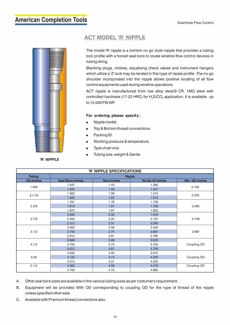
ACT MODEL ‘R’ NIPPLE
The model 'R' nipple is a bottom no go style nipple that provides a tubing
lock profile with a honed seal bore to locate wireline flow control devices in
tubing string.
Blanking plugs, chokes, equalizing check valves and instrument hangers
which utilize a 'Z' lock may be landed in this type of nipple profile. The no-go
shoulder incorporated into the nipple allows positive locating of all flow
control equipments used during wireline operations.
ACT nipple is manufactured from low alloy steel/9 CR. 1MO steel with
controlled hardness (17-22 HRC) for H S/CO application. It is available up 2 2
to 15,000 PSI WP.
For ordering please specify :
! Nipple model.
! Top & Bottom thread connections.
! Packing ID.
! Working pressure & temperature.
! Type of service.
! Tubing size, weight & Garde.
A. Other seal bore sizes are available in the various tubing sizes as per costumer's requirement.
B. Equipment will be provided With OD corresponding to coupling OD for the type of thread of the nipple
unless specified otherwise.
C. Available with Premium thread connections also.
‘R’ NIPPLE SPECIFICATIONS
1.900
2.1/16
2.109
2.250
Tubing Nipple
OD-Inches Seal Bore-Inches Size-Inches No-Go ID-Inches Min. OD Inches
1.437 1.43 1.385
1.500 1.50 1.447
1.562 1.56 1.510
1.625 1.62 1.572
1.781 1.78 1.728
2.3/8 1.812 1.81 1.760 2.560
1.875 1.87 1.822
2.062 2.06 1.978
2.7/8 2.250 2.25 2.197 3.109
2.312 2.31 2.260
2.562 2.56 2.442
3.1/2 2.750 2.75 2.697 3.687
2.812 2.81 2.760
3.688 3.68 3.625
4.1/2 3.750 3.75 3.700 Coupling OD
3.812 3.81 3.759
4.000 4.00 3.910
5.00 4.125 4.12 4.035 Coupling OD
4.312 4.31 4.223
5.1/2 4.562 4.56 4.472 Coupling OD
4.750 4.75 4.660
‘R’ NIPPLE
14
Downhole Flow Control

The ACT model PCMD and PCMU sliding sleeve
provides a means of communication between
the tubing and the annulas. It has internal honed
seal bores located in top and bottom housing for
placement of flow control devices. The internal
sleeve is shif ted open or closed by using a B
type wireline shif ting tool. ACT model PCMD is
down shif t to open and PCMU is up shif t to open
sliding sleeve.
ACT PCMD Sliding Sleeve can be converted to
PCMU or vice versa by changing the upper and
lower subs.
ACT MODEL ‘PCMD’ AND ‘PCMU’ SLIDING SLEEVE
PCMD AND PCMU DATA SHEET
2.7/8” 2.3/8” 2.7/8” 3.1/2” 4” 4.1/2” 5.1/2”
SEAL BORE 1.81 1.87 2.31 2.56 2.75 2.81 3.31 3.75 3.81 4.43
MAX. OD 3.75 3.080 3.750 4.280 4.280 4.280 5.520 5500 6.500
MIN. ID 1.830 1.990 2.375 2.610 2.775 2.825 3.395 3.895 4.500
TOTAL LENGTH 48.10 48.99 48.63 51.67 52.37 50.00 55.25 54.89 54.30 60.64
CLOSED EQUALIZED OPEN
15
Downhole Flow Control

ACT MODEL ‘L’ SLIDING SLEEVE
The ACT Model ‘L’ sliding sleeve is a downhole tool used to
establish communication, when desired, between the
tubing and annulus. Selective and /or top No-Go locking
devices are available for use with the sleeve. It has seal
bores above and below the ports, and a top No-Go
shoulder and locking groove.
The ‘L’ sliding sleeve locates, seals and retains flow control
accessories that have either top No-Go or selective locks.
ACT Model ‘L’ sliding sleeve is manufactured for standard
H S and H S - CO services.2 2 2
Tubing Sliding Sleeve
ID-Inches Seal Bore Inches Size-Inches OD-Inches
1.437 1.43
1.500 1.50
1.562 1.56
1.625 1.62
1.781 1.78
2.3/8 1.812 1.81 2.910
1.875 1.87
2.250 2.25
2.312 2.31
2.750 2.75
2.812 2.81
3.688 3.68
3.812 3.81
4.313 4.31
4.562 4.56
‘L’ SLIDING SLEEVE SPECIFICATIONS
1.900
2.1/16
2.7/8
3.1/2
4.1/2
5.1/2
2.375
2.500
3.410
4.500
5.500
Coupling OD
CLOSED OPEN
16
Downhole Flow Control

Running / Pulling Tools
X RUNNING
TOOL
RXN RUNNING TOOL
GS PULLING TOOL
17
GU SHEAR UP ADAPTER
JD PULLING TOOL
JU PULLING TOOL
RUNNING / PULLING TOOLS

S PULLING TOOL
BO POSITIONING
TOOL
BO SELECTIVE POSITIONING
TOOL
X SELECTIVE POSITIONING
TOOL
R PULLING TOOL
18
OPENINGPOSITION
CLOSINGPOSITION
D-2 SHIFTING TOOL
Running / Pulling Tools
RUNNING / PULLING TOOLS
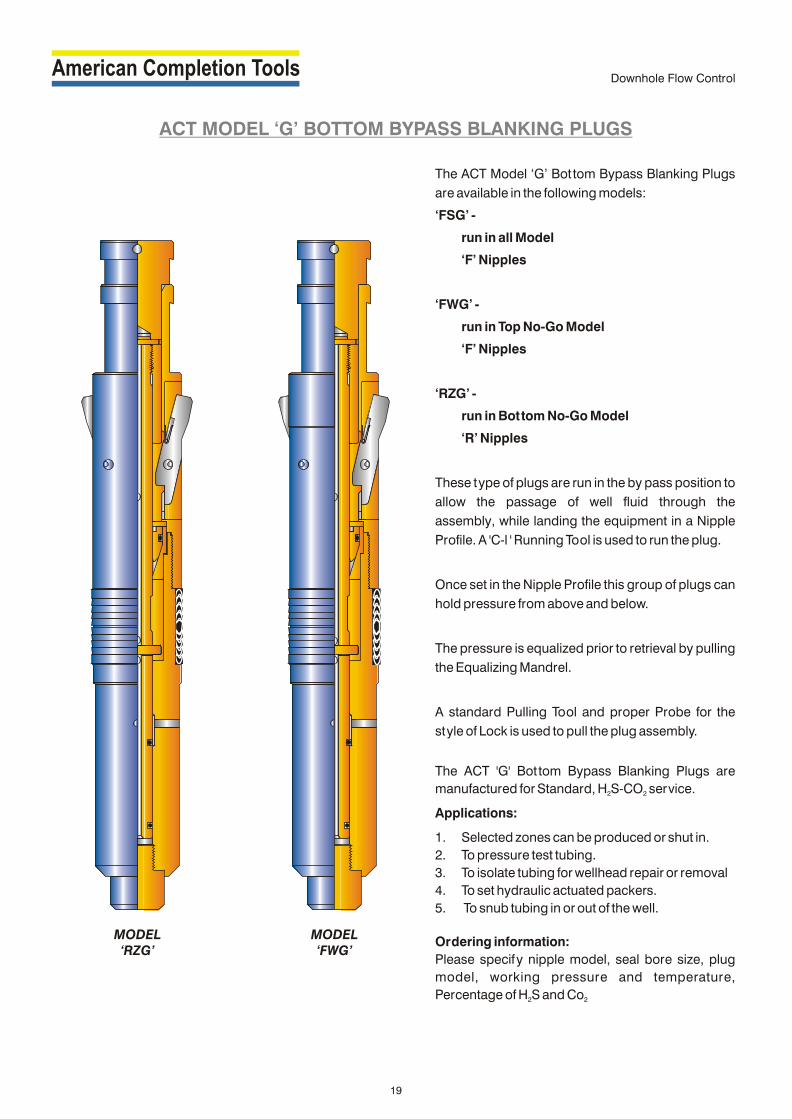
ACT MODEL ‘G’ BOTTOM BYPASS BLANKING PLUGS
The ACT Model ‘G’ Bottom Bypass Blanking Plugs
are available in the following models:
‘FSG’ -
run in all Model
‘F’ Nipples
‘FWG’ -
run in Top No-Go Model
‘F’ Nipples
‘RZG’ -
run in Bottom No-Go Model
‘R’ Nipples
These type of plugs are run in the by pass position to
allow the passage of well fluid through the
assembly, while landing the equipment in a Nipple
Profile. A 'C-l ' Running Tool is used to run the plug.
Once set in the Nipple Profile this group of plugs can
hold pressure from above and below.
The pressure is equalized prior to retrieval by pulling
the Equalizing Mandrel.
A standard Pulling Tool and proper Probe for the
style of Lock is used to pull the plug assembly.
The ACT 'G' Bottom Bypass Blanking Plugs are
manufactured for Standard, H S-CO service.2 2
Applications:
1. Selected zones can be produced or shut in.
2. To pressure test tubing.
3. To isolate tubing for wellhead repair or removal
4. To set hydraulic actuated packers.
5. To snub tubing in or out of the well.
Ordering information:
Please specify nipple model, seal bore size, plug
model, working pressure and temperature,
Percentage of H S and Co2 2
MODEL‘FWG’
MODEL‘RZG’
19
Downhole Flow Control

Tubing Nipple Accessory
Availability
Tubing Size Nipple Size Plug Type
ID Inches Seal Bore ‘FWG’ Size
Inches
1.900 1.437 1.43
1.500 -
2.1/16 1.562 1.56
1.625 -
1.781 1.78
2.3/8 1.812 1.81
1.875 -
2.062 2.06
2.7/8 2.250 2.25
2.312 -
2.562 2.56
3.1/2 2.750 2.75
2.812 -
3.688 3.68
4.1/2 3.750 3.75
3.812 -
To Run To Pull
‘C-1’ Equalizing Plug
Running Tool Mandrel Assembly
Pulling Tool Type B Probe
Size Inches OTIS CAMCO Size
Inches
1.900 40RB14 JUC15174 1.900
2.1/16 40SB6 JDC15154 2.1/16
40RB17 JUC15185
2.3/8 2.3/8
40SB1 JDC15169
40RB18 JUC15189
2.7/8 2.7/8
40SB2 JDC15171
40RB19 JUC15191
3.1/2 3.1/2
40SB9 JDC15181
40RB20 JUC15193
4.1/2 4.1/2
40SB10 JDC15183
FWG Dimension Specifications
Equalizing Plug Lock Mandrel
Mandrel Maximum
Fishing Neck Fishing Plug OD
Neck ID
OD Inches OD Inches ID Inches OD Inches
1.490
1.188 1.188 0.750 -
1.615
-
1.865
1.375 1.375 0.875 1.865
-
2.115
1.750 1.750 1.188 2.302
-
2.625
2.313 2.313 1.438 2.802
-
3.740
3.125 3.125 2.062 3.802
-
‘FWG’ BYPASS BLANKING PLUG SPECIFICATIONS
Tubing Nipple Accessory
Availability
Tubing Size Nipple Size Plug Type
ID Inches Seal Bore ‘RZG’ Size
Inches
1.900 1.437 1.43
1.500 1.50
2.1/16 1.562 1.56
1.625 1.62
1.781 1.78
2.3/8 1.812 1.81
1.875 1.87
2.062 2.06
2.7/8 2.250 2.25
2.312 2.31
2.562 2.56
3.1/2 2.750 2.75
2.812 2.81
3.688 3.68
4.1/2 3.750 3.75
3.812 3.81
To Run To Pull
‘C-1’ Equalizing Plug
Running Tool Mandrel Assembly
Pulling Tool Type B Probe
Size Inches OTIS CAMCO Size
Inches
1.900 40RB14 JUC15174 1.900
2.1/16 40SB6 JDC15154 2.1/16
40RB17 JUC15185
2.3/8 2.3/8
40SB1 JDC15169
40RB18 JUC15189
2.7/8 2.7/8
40SB2 JDC15171
40RB19 JUC15191
3.1/2 3.1/2
40SB9 JDC15181
40RB20 JUC15193
4.1/2 4.1/2
40SB10 JDC15183
RZG Dimension Specifications
Equalizing Plug Lock Mandrel
Mandrel Maximum
Fishing Neck Fishing Plug OD
Neck ID
OD Inches OD Inches ID Inches OD Inches
1.472
1.188 1.188 0.750 1.490
1.552
1.615
1.771
1.375 1.375 0.875 1.802
1.865
2.052
1.750 1.750 1.188 2.240
2.302
2.552
2.313 2.313 1.438 2.740
2.802
3.678
3.125 3.125 2.062 3.740
3.802
‘RZG’ BYPASS BLANKING PLUG SPECIFICATIONS
ACT MODEL ‘G’ BOTTOM BYPASS BLANKING PLUGS
20
Downhole Flow Control

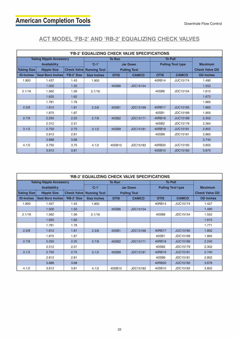
ACT MODEL ‘FB-2’ AND ‘RB-2’ EQUALIZING CHECK VALVES
The ACT Model 'FB-2' and 'RB-2' Equalizing Check
Valves are complete equipment units, without any
Locking Device. They are utilized in the following Tubing
Mounted Equipment:
‘FB-2’
run in all Model ‘F’ Nipples and all Model
‘L’ Sliding Sleeves
‘RB-2’
run in Bottom No-Go
‘R’ Nipples
Both models are run into a Nipple Profile and hold
pressure from above only. The 'FB-2' model lands on the
top of a 'F' Nipple Profile seal bore. The 'RB2' model seats
on the Bottom No-Go Shoulder of a ‘R' Nipple
A ‘C-1’ Running Tool is used to run both valve
assemblies.
Both models can be equalized prior to retrieval, by
shif ting open the Equalizing Mandrel Ports. Standard
Pulling Tool is utilized for retrieval of these valves.
The ACT 'FB-2' and RB-2' Equalizing Check Valves are
manufactured for Standard, H S and H S-CO service.2 2 2
Applications :
1. Can be used as a plug to pressure test tubing.
2. To set hydraulically actuated packer with the check
valve positioned below the packer.
3. For gas lif t operations.
4. To be used as a standing valve in wells which have
downhole electric pumps.
Ordering information :
Please specify nipple model, seal bore size, check valve
model, working pressure and temperature, percentage
of H S and Co2 2
MODEL‘FB-2’
MODEL‘RB-2’
21
Downhole Flow Control
Tubing Nipple Accessory
Availability
Tubing Size Nipple Size Check Valve
ID-Inches Seal Bore Inches ‘FB-2’ Size
1.900 1.437 1.43
1.500 1.50
2.1/16 1.562 1.56
1.625 1.62
1.781 1.78
2.3/8 1.812 1.81
1.875 1.87
2.7/8 2.250 2.25
2.312 2.31
3.1/2 2.750 2.75
2.812 2.81
3.688 3.68
4.1/2 3.750 3.75
3.812 3.81
To Run
‘C-1’ Jar Down
Running Tool Pulling Tool
Size Inches OTIS CAMCO
1.900
40SB6 JDC15154
2.1/16
2.3/8 40SB1 JDC15169
2.7/8 40SB2 JDC15171
3.1/2 40SB9 JDC15181
4.1/2 40SB10 JDC15183
To Pull
Pulling Tool type Maximum
Check Valve OD
OTIS CAMCO OD Inches
40RB14 JUC15174 1.490
1.552
40SB6 JDC15154 1.615
1.672
1.865
40RB17 JUC15185 1.865
40SB1 JDC15169 1.905
40RB18 JUC15189 2.302
40SB2 JDC15179 2.364
40RB19 JUC15191 2.802
40SB9 JDC15181 2.865
3.740
40RB20 JUC15193 3.802
40SB10 JDC15183 3.875
‘FB-2’ EQUALIZING CHECK VALVE SPECIFICATIONS
Tubing Nipple Accessory
Availability
Tubing Size Nipple Size Check Valve
ID-Inches Seal Bore Inches ‘RB-2’ Size
1.900 1.437 1.43
1.500 1.50
2.1/16 1.562 1.56
1.625 1.62
1.781 1.78
2.3/8 1.812 1.81
1.875 1.87
2.7/8 2.250 2.25
2.312 2.31
3.1/2 2.750 2.75
2.812 2.81
3.688 3.68
4.1/2 3.812 3.81
To Run
‘C-1’ Jar Down
Running Tool Pulling Tool
Size Inches OTIS CAMCO
1.900
40SB6 JDC15154
2.1/16
2.3/8 40SB1 JDC15169
2.7/8 40SB2 JDC15171
3.1/2 40SB9 JDC15181
4.1/2 40SB10 JDC15183
To Pull
Pulling Tool type Maximum
Check Valve OD
OTIS CAMCO OD Inches
40RB14 JUC15174 1.427
1.490
40SB6 JDC15154 1.552
1.615
1.771
40RB17 JUC15185 1.802
40SB1 JDC15169 1.865
40RB18 JUC15189 2.240
40SB2 JDC15179 2.302
40RB19 JUC15191 2.740
40SB9 JDC15181 2.802
40RB20 JUC15193 3.678
40SB10 JDC15183 3.802
‘RB-2’ EQUALIZING CHECK VALVE SPECIFICATIONS
ACT MODEL ‘FB-2’ AND ‘RB-2’ EQUALIZING CHECK VALVES
22
Downhole Flow Control
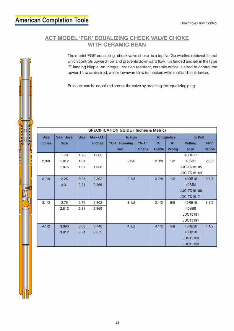
ACT MODEL ‘FGK’ EQUALIZING CHECK VALVE CHOKEWITH CERAMIC BEAN
The model 'FGK' equalizing check valve choke is a top No-Go wireline retrievable tool
which controls upward flow and prevents downward flow. It is landed and set in the type
‘F’ landing Nipple. An integral, erosion resistant, ceramic orifice is sized to control the
upward flow as desired, while downward flow is checked with a ball and seat device.
Pressure can be equalized across the valve by breaking the equalizing plug.
SPECIFICATION GUIDE ( Inches & Metric)
Size Seal Bore Size Max O.D. To Run To Equalize To Pull
Inches Size Inches “C-1” Running “N-1” ‘A’ ‘A’ Pulling “N-1”
Tool Shank Guide Prong Tool Probe
1.78 1,78 1.865 40RB17
2.3/8 1.812 1.81 2.3/8 2.3/8 1/2 40SB1 2.3/8
1.875 1.87 1.928 JUC-TD15185
JDC-TD15169
2.7/8 2.25 2.25 2.302 2.7/8 2.7/8 1/2 40RB18 2.7/8
2.31 2.31 2.365 40SB2
JUC-TD15189
JDC-TD15171
3.1/2 2.75 2.75 2.802 3.1/2 3.1/2 5/8 40RB19 3.1/2
2.812 2.81 2.865 40SB9
JDC15181
JUC15191
4.1/2 3.688 3.68 3.740 4.1/2 4.1/2 5/8 40RB20 4.1/2
3.812 3.81 3.875 40SB10
JDC15183
JUC15193
23
Downhole Flow Control

ACT MODEL ‘LGE’ SEPARATION SLEEVE
The model ‘LGE’ Separation Sleeve is a Top No-Go device which is run on wireline and
designed to be landed and set in the type ‘L’ sliding sleeve. These are equipped with two
packing assemblies, that seal of f the upper and lower seal bore of sliding sleeve,
Therefore isolating the sleeve ports. Production can be maintained by producing the well
through the inside diameter of the tool. The separation Sleeve is also designed with an
internal equalizing plug to equalize pressure before retrieving.
24
SPECIFICATION GUIDE ( Inches & Metric)
Size Seal Bore Size Max O.D. To Run To Equalize To Pull
Inches Size Inches “C-1” Running “N-1” ‘A’ ‘A’ Pulling “N-1”
Tool Shank Guide Prong Tool Probe
1.78 1,78 1.865 40RB17
2.3/8 1.812 1.81 2.3/8 2.3/8 1/2 40SB1 2.3/8
1.875 1.87 1.928 JUC-TD15185
JDC-TD15169
2.7/8 2.25 2.25 2.302 2.7/8 2.7/8 1/2 40RB18 2.7/8
2.31 2.31 2.365 40SB2
JUC-TD15189
JDC-TD15171
3.1/2 2.75 2.75 2.802 3.1/2 3.1/2 5/8 40RB19 3.1/2
2.812 2.81 2.865 40SB9
JDC15181
JUC15191
4.1/2 3.688 3.68 3.740 4.1/2 4.1/2 5/8 40RB20 4.1/2
3.812 3.81 3.875 40SB10
JDC15183
JUC15193
Downhole Flow Control

ACT MODEL ‘LGK’ EQUALIZING CHECK VALVE CHOKE WITH CERAMIC BEAN
The model ‘LGK’ equalizing check valve choke is a Top No-Go wireline retrievable tool
which controls upward flow and prevents downward flow. It is landed and set in the type ‘L’
sliding sleeve. An integral, erosion resistant, ceramic orifice is sized to control the upward
flow as desired, while downward flow is checked with a ball and seat device.
Pressure can be equalized across the valve by breaking the equalizing plug.
25
SPECIFICATION GUIDE ( Inches & Metric)
Size Seal Bore Size Max O.D. To Run To Equalize To Pull
Inches Size Inches “C-1” Running “N-1” ‘A’ ‘A’ Pulling “N-1”
Tool Shank Guide Prong Tool Probe
1.78 1,78 1.865 40RB17
2.3/8 1.812 1.81 2.3/8 2.3/8 1/2 40SB1 2.3/8
1.875 1.87 1.928 JUC-TD15185
JDC-TD15169
2.7/8 2.25 2.25 2.302 2.7/8 2.7/8 1/2 40RB18 2.7/8
2.31 2.31 2.365 40SB2
JUC-TD15189
JDC-TD15171
3.1/2 2.75 2.75 2.802 3.1/2 3.1/2 5/8 40RB19 3.1/2
2.812 2.81 2.865 40SB9
JDC15181
JUC15191
4.1/2 3.688 3.68 3.740 4.1/2 4.1/2 5/8 40RB20 4.1/2
3.812 3.81 3.875 40SB10
JDC15183
JUC15193
Downhole Flow Control

ACT MODEL ‘LGU’ BYPASS CHOKE
The TYPE "LGU" BY-PASS CHOKE is a Top No-Go device which is run on wireline and designed
to be landed and set in the Type "L" Sliding Sleeve ideally suited for commingled production.
The BY -PASS CHOKE is equipped with a ceramic flow choke which controls the flow of the
zone being produced through the Sliding Sleeve. Production from the other zone flows thru the
bypass, but is prevented from back flowing through the choke and the Sliding Sleeve by an API
ball and seat back check valve.
26
SPECIFICATION GUIDE ( Inches & Metric)
Size Seal Bore Size Max O.D. To Run To Pull
Inches Size Inches “C-1” Running “N-1” Pulling “N-1”
Tool Shank Tool Probe
1.78 1,78 1.865 40RB17
2.3/8 1.812 1.81 2.3/8 40SB1 2.3/8
1.875 1.87 1.928 JUC-TD15185
JDC-TD15169
2.7/8 2.25 2.25 2.302 2.7/8 40RB18 2.7/8
2.31 2.31 2.365 40SB2
JUC-TD15189
JUC-TD15171
3.1/2 2.75 2.75 2.802 3.1/2 40RB19 3.1/2
2.812 2.81 2.865 40SB9
JDC15181
JUC15191
4.1/2 3.688 3.68 3.740 4.1/2 40RB20 4.1/2
3.812 3.81 3.875 40SB10
JDC15183
JUC15193
Downhole Flow Control

ACT MODEL ‘B’ DOWNHOLE INSTRUMENT HANGERS
Model ‘FSB’ Model ‘FWB’ Model ‘RZB’
Tubing Nipple Accessory
Availability
Tubing Size Nipple Size Instrument
Hanger
OD Inches Seal Bore ‘FSB’ Size
Inches
1.900 1.437 1.43
1.500 1.50
2.1/16 1.562 1.56
1.625 1.62
1.781 1.78
2.3/8 1.812 1.81
1.875 1.87
2.7/8 2.062 2.06
2.250 2.25
2.312 2.31
3.1/2 2.562 2.56
2.750 2.75
2.812 2.81
4.1/2 3.688 3.68
3.750 3.75
3.812 3.81
To Run
Running Tool
‘C-1’Running Tool Attachment
Running Locating With ‘A’ Shank
Selective NoGo-ring
Size-Inches Size-Inches Size-Inches
1.900 1.468 1.900
1.520
2.1/16 1.593 2.1/16x4-3/4
1.656
1.807
2.3/8 1.843 2-3/8x5
1.906
2.7/8 2.093 2-7/8x5-5/16
2.281
2.343
3.1/2 2.593 3.1/2x5-5/16
2.781
2.843
4.1/2 3.718 4-1/2x7
3.781
3.835
To Pull
Pulling Tool Type ‘A’ Probe
OTIS CAMCO Size-Inches
40RB14 JUC15174 1.900
40SB6 JDC15154 2.1/16
40RB17 JUC15185
40SB1 JDC15169 2.3/8
40SB18 JUC15189 2.7/8
40SB2 JDC15181
40RB19 JUC15191 3.1/2
40SB9 JDC15181
40RB20 JUC15193 4.1/2
40SB10 JDC15183
Maximum
Tool OD
OD Inches
1.427
1.427
1.552
1.552
1.771
1.802
1.802
2.052
2.240
2.240
2.552
2.740
2.740
3.678
3.740
3.802
ACT ‘FSB’ INSTRUMENT HANGER SPECIFICATIONS
The ACT Model 'B' Downhole instrument Hangers are available in the
following models:
'FSB’
run in all Model
'F’ Nipples
'FWB' -
run in Top No-Go Model
'F' Nipples
'RZB'
run in Bottom No-Go
‘R' Nipples
These type of hangers are used to hang instruments such as
Pressure and Temperature Gauges in a Nipple Profile. Recorders are
held securely 'in place when recording data during high production
rates. Pressure data is easily correlated between runs, as recorders
are always landed at the same depth. The hangers permit
simultaneous surveys to be done on several zones at the same time.
Standard wireline equipment is used to set and retrieve all three
models.
The ACT Model 'B' Downhole Instrument Hangers are manufactured
for Standard H2S and H S-CO service.2 2
Ordering information :
Please specify nipple model, seal bore size, hanger model.
percentage of H S and Co2 2
27
Downhole Flow Control

Tubing Nipple Accessory
Availability
Tubing Size Nipple Size Instrument
Hanger
OD Inches Seal Bore ‘FWB’ Size
Inches
1.900 1.437 1.43
1.500 -
2.1/16 1.562 1.56
1.625 -
1.781 1.78
2.3/8 1.812 1.81
1.875 -
2.7/8 2.062 2.06
2.250 2.25
2.312 -
3.1/2 2.562 2.56
2.750 2.75
2.812 -
4.1/2 3.688 3.68
3.750 3.75
3.812 -
To Run
Running Tool
Attachments
‘C-1’ Running Tool ‘A’ Shank
Dogs Retracted
Size Inches Size Inches
1.900 1.900
2.1/16 2.1/16x5-7/8
2.3/8 2.3/8x6-1/8
2.7/8 2.7/8x6-3/32
3-1/2 3-1/2x6-11/16
4.1/2 4.1/2x6-1/2
To Pull
Pulling Tool Type ‘B’ Probe
OTIS CAMCO Size-Inches
40RB14 JUC15174 1.900
40SB6 JDC15154 2.1/16
40RB17 JUC15185
2.3/8
40SB1 JDC15169
40RB18 JUC15189
40SB2 JDC15171 2.7/8
40RB19 JUC15191
40SB9 JDC15181 3.1/2
40RB20 JUC15193 4.1/2
40SB10 JDC15183
Maximum
Tool OD
OD Inches
1.490
-
1.615
-
1.865
1.865
-
2.115
2.302
-
2.625
2.802
-
3.740
3.802
-
ACT ‘FWB’ INSTRUMENT HANGER SPECIFICATIONS
ACT MODEL ‘B’ DOWNHOLE INSTRUMENT HANGERS
Tubing Nipple Accessory
Availability
Tubing Size Nipple Size Instrument
Hanger
OD Inches Seal Bore ‘RZB’ Size
Inches
1.900 1.437 1.43
1.500 1.50
2.1/16 1.562 1.56
1.625 1.62
1.781 1.78
2.3/8 1.812 1.81
1.875 1.87
2.7/8 2.062 2.06
2.250 2.25
2.312 2.31
3.1/2 2.562 2.56
2.750 2.75
2.812 2.81
4.1/2 3.688 3.68
3.750 3.75
3.812 3.81
To Run
Running Tool
Attachments
‘C-1’ Running Tool ‘A’ Shank
Dogs Retracted
Size Inches Size Inches
1.900 1.900
2.1/16 2.1/16x5-7/8
2.3/8 2.3/8x6-1/8
2.7/8 2.7/8x6-3/32
3-1/2 3-1/2x6-11/16
4.1/2 4.1/2x6-1/2
To Pull
Pulling Tool Type ‘B’ Probe
OTIS CAMCO Size-Inches
40RB14 JUC15174 1.900
40SB6 JDC15154 2.1/16
40RB17 JUC15185
2.3/8
40SB1 JDC15169
40RB18 JUC15189
40SB2 JDC15171 2.7/8
40RB19 JUC15191
40SB9 JDC15181 3.1/2
40RB20 JUC15193
40SB10 JDC15183 4.1/2
Maximum
Tool OD
OD Inches
1.427
1.490
1.552
1.615
1.771
1.802
1.865
2.052
2.240
2.302
2.552
2.740
2.802
3.678
3.740
3.802
ACT ‘RZB’ INSTRUMENT HANGER SPECIFICATIONS
28
Downhole Flow Control

PREMIUM BRIDGE PLUG
BKR-1BRIDGE PLUG WIRELINE SET
LITE BRIDGE PLUG
BALL CHECKCEMENT RETAINER
BKR-1CEMENT RETAINER
WIRELINE SET
BKR-1BRIDGE PLUG
MECHANICAL SET
BKRCEMENT RETAINERMECHANICAL SET
BKRMECHANICAL
SETTING TOOL
FH & HYDROMECHANICAL
SETTING TOOL
BRIDGE PLUGS, CEMENT RETAINERS
29
Bridge Plugs, Cement Retainers
FURYHYDRAULIC
SETTING TOOL
ELECTRIC LINE
SETTING TOOL
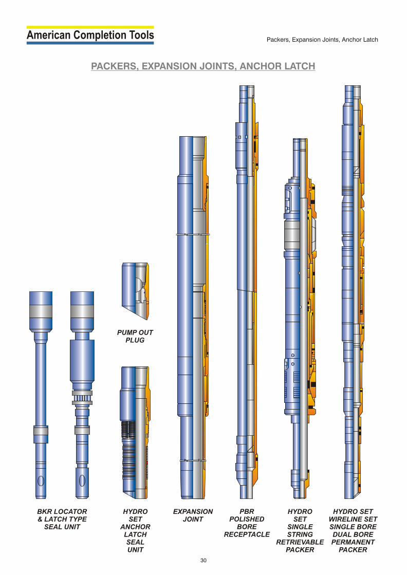
PACKERS, EXPANSION JOINTS, ANCHOR LATCH
HYDRO SET
SINGLE STRING
RETRIEVABLE PACKER
HYDRO SETWIRELINE SETSINGLE BORE DUAL BORE PERMANENT
PACKER
PBRPOLISHED
BORE RECEPTACLE
HYDRO SET
ANCHORLATCHSEAL UNIT
EXPANSIONJOINT
30
Packers, Expansion Joints, Anchor Latch
PUMP OUTPLUG
BKR LOCATOR& LATCH TYPE
SEAL UNIT

INJECTION PRESSURE OPERATED GAS LIFT VALVE
DESCRIPTION
ACT N Series Valves utilize a nitrogen charged dome and bellow configuration designed for either continuous or
intermit tent flow applications. They are especially suitable for use as unloading and operating valves in areas where
high gas lif t pressures are available. Since the charge pressure above the bellows is af fected by temperature, it is
important that the operating temperatures at the valve be known. These valve are available in both wireline-
retrievable and conventional installations.
BENEFITS
Vibration protected, 3-ply monel bellow are designed to withstand hydrostatic pressure up to 5000 psi.
Nitrogen dome charge, acting on the O.D. of the bellow, permits bellows to expand uniformly without stacking, thus
prolonging bellow's life.
The multiple por t size availability, make this valve series appropriate for a wide range of operating conditions.
Reversible seat available in several dif ferent materials.
OPERATING PRINCIPLE
The dome nitrogen charge applied to the ex ternal area of the bellows provides the downward force, holding the
valve on its seat. This dome pressure is preset at the reference temperature and corrected to operating temperature.
The opening forces on the valve are the casing pressure acting on the internal area of the bellows (less the area of the
seat) and the tubing pressure acting on the seat area. When the combined casing and tubing pressures are
suf ficient, the valve opens. Once the valve is open, it remains open until the casing pressure is reduced to the
predetermined closing pressure. The spread (the dif ference between opening and closing casing pressure) is
controlled by the tubing sensitivity of the valve. The larger the seat por t area, the more tubing sensitive the valve
is.
ACT HIGH PRESSURE GAS LIFT VALVE
ACT High Pressure Gas Lif t Valve incorporates concept of piston cylinder in true sense, which was not in old Gas Lif t
Valve available in the market. Bellow is protected in this new design against deformation and remain not only straight
but its coil are not also over stressed against high pressure. Due to this bellow’s life gets increased and valve
functions in a predetermined manner.
ENGINEERING DATA FOR INJECTION PRESSURE OPERATED VALVES
TYPE ASSY. NO. NOMINAL PACKING OD PORT SIZE LATCH OR RUNNING PULLING MANDREL OD (INCH) (INCH) END CONN. TOOL TOOL TYPE
(INCH) UPPER LOWER MIN MAX TYPE TYPE
N-90 122-10XX-XXX-XO 1-1/2 – – 1/8 1/2 1” or 1/2” NPT – – SERIES 15
N-90R 122-10XX-XXX-X1 1-1/2 1-9/16 1-1/2 1/8 1/2 TG, RK, RM, T-2 RTG, TER PTG, TRP TP, MM, MMA, MMG
N-90R(H) 122-11XX-320-01 1-1/2 1-9/16 1-1/2 1/8 1/2 TG, RK, RM, T-2 RTG, TER PTG, TRP TP, MM, MMA, MMG
NM-90 122-20XX-XXX-XO 1 – – 1/8 3/8 1/2” NPT – – SERIES 12
NM-90R 122-20XX-XXX-X1 1 1-1/32 1-1/32 1/8 3/8 BK-2, M MR MP TMP, KBM, KBMG, KBG
PBK-1 122-90XX-XXX-X1 1 1-1/32 1-1/32 1/8 3/8 Integral Bot tom GA-2 MP TMP, KBM, KBMG, KBG
Gas Lif t Equipment
31
NEW
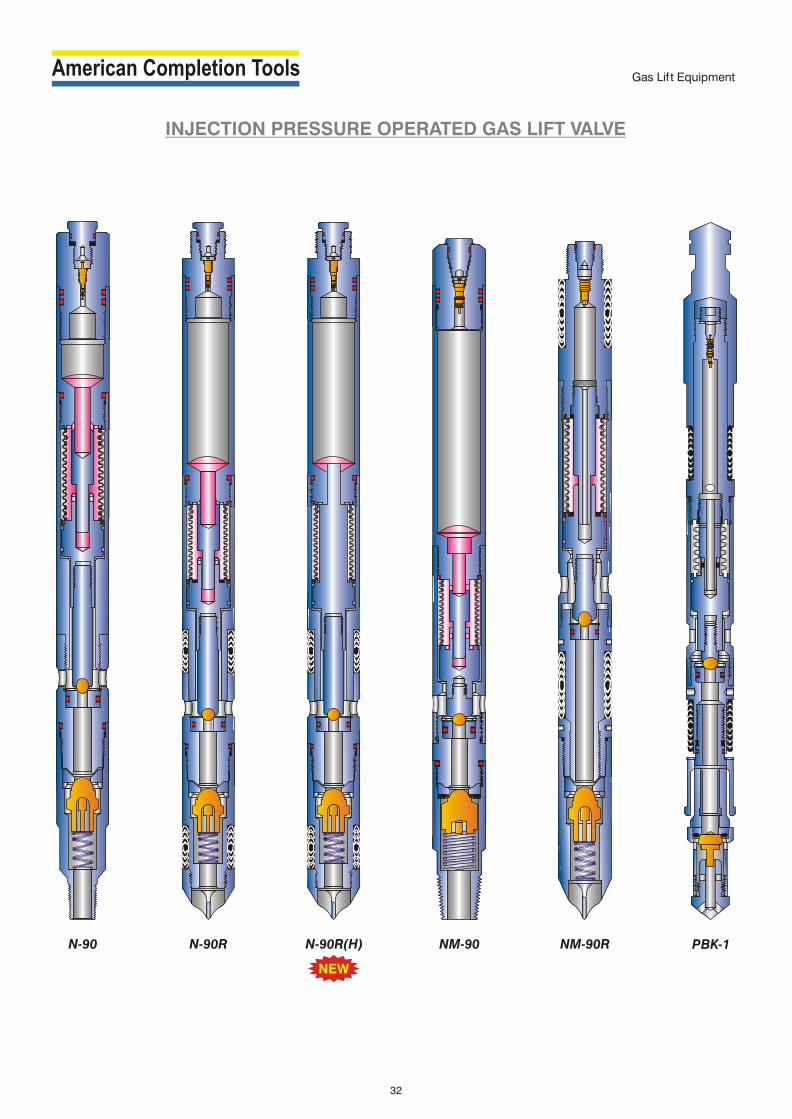
NM-90RN-90 N-90R NM-90 PBK-1
Gas Lif t Equipment
INJECTION PRESSURE OPERATED GAS LIFT VALVE
32
N-90R(H)
NEW

TMP and TP Series Side Pocket Mandrel :
ACT TMP and TP Series Side Pocket Mandrels are consisting of
forged pocket with integral tool discriminator, oval pipe, swages and
orienting sleeves. Its orienting sleeve allows precise and proper
alignment during the insertion of positioning devices / tools into the
side pocket. Forged tool discriminator guides the proper diameter
side pocket devices/tools into the mandrel pocket and deflects
larger tools into the tubing bore to prevent damage to the
positioning devices/tools.
In Gas Lif t applications, high pressure gas injected into the casing
annulus flows through the ports of the pocket in the gas lif t valve and
into the tubing. The standard pocket is ported between the seal
bores to communicate with the casing annulus and the gas is
circulated down the annulus through the gas lif t valve into the
tubing. These mandrels are used for tubing flow applications.
Both TMP and TP series feature multiple porting variations for
specific applications i.e. annulus flow, chamber lif t, fluid injection
water flood installations.
TMP and TPC Series Side Pocket Mandrel :
These mandrels are used in annulus flow applications in which a
snorkel functions as an exhaust port. Snorkel located at the bottom
of the side pocket, extends downward into casing annulus. The
holes in the mandrel side pocket directly communicate with the
tubing. High pressure gas injected into the tubing flows thru the port
between the packing bores into the pocket of the mandrel, then thru
the ports into the gas lif t valve, downward through the snorkel and
then finally into the casing.
TMPE and TPE Series Side Pocket Mandrel :
These mandrels mainly used in chamber lif t applications. It has no
ports in the side pocket for communication with the tubing. Instead
of that, an exhaust port is located at the bottom of the side pocket.
This port is extended downward into the casing annulus through a
½” pipe connected to the top packer of a chamber lif t installation. In
gas lif t application, high pressure gas is injected into the casing
annulus flows through the ports in the side of the mandrel, then
through the ports in the gas lif t valve and finally downward to the
exhaust port.
TMPS and TPS Series Side Pocket Mandrel :
These mandrels are used in single string, multi zone fluid injection
water flood installations. The casing exhaust port located at the
bottom of the side pocket is used to protect the casing from high
velocity turbulence related with water flooding. In water flood
operations, water injected into the tubing flows into the mandrel side
pocket, thru the water flood flow regulator valve and downward
through he exhaust port. A non retrievable check valve can be
at tached directly to the exhaust port to prevent back flow from the
annulus when the water flood regulator valve is removed.
E UPP RW GES A
NT GRAL I EITH ODYW B
ORIENTING SLEEVES
OV L ABODY
L ER OWSWA EGINTE RAL GW TH I
ODYB
VIEW - XX
I - XV EW XB
C
B
C
SIDE POCKET MANDREL
¯E
¯F
¯D
TMPS I S M ELER E ANDRFO 1 O.D. VALVER ”WEL D SWAGES( DE )
TPSERIES MANDREL
FOR 1.1/2” O.D. VALVEEG(INT RAL SWAGES)
AL OVPIPE
LOWERS AGE W
U PE P RSWAGE
O ETP CK
NORIENTI GV SSLEE E
¯F
¯E
¯D
A
Gas Lif t Equipment
33
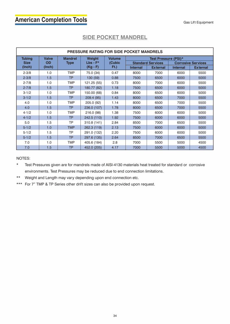
2-3/8 1.0 TMP 75.0 (34) 0.47 8000 7000 6000 5500
2-3/8 1.5 TP 130 (59) 0.88 7500 6500 6000 5000
2-7/8 1.0 TMP 121.25 (55) 0.73 8000 7000 6000 5500
2-7/8 1.5 TP 180.77 (82) 1.18 7500 6500 6000 5000
3-1/2 1.0 TMP 150.00 (68) 0.84 8000 6500 6000 5000
3-1/2 1.5 TP 209.4 (95) 1.43 8000 6500 7000 5500
4.0 1.0 TMP 205.0 (92) 1.14 8000 6500 7000 5500
4.0 1.5 TP 236.0 (107) 1.78 8000 6500 7000 5500
4-1/2 1.0 TMP 216.0 (98) 1.38 7500 6000 6000 5000
4-1/2 1.5 TP 242.5 (110) 1.92 7500 6000 6000 5000
5.0 1.5 TP 310.8 (141) 2.84 8500 7000 6500 5500
5-1/2 1.0 TMP 262.3 (119) 2.13 7500 6000 6000 5000
5-1/2 1.5 TP 291.0 (132) 2.20 7500 6000 6000 5000
5-1/2 1.5 TP 297.6 (135) 2.64 8500 7000 6500 5500
7.0 1.0 TMP 405.6 (184) 2.8 7000 5500 5000 4500
7.0 1.5 TP 452.0 (205) 4.17 7000 5500 5000 4500
Tubing Size
(Inch)
ValveOD
(Inch)
Mandrel Type
Weight Lbs - F*(Kg - F)
Volume(Cubic
Ft.) Internal External
Standard Services
Internal External
Corrosive Services
Test Pressure (PSI)*
PRESSURE RATING FOR SIDE POCKET MANDRELS
NOTES:
* Test Pressures given are for mandrels made of AISI-4130 materials heat treated for standard or corrosive
environments. Test Pressures may be reduced due to end connection limitations.
** Weight and Length may vary depending upon end connection etc.
*** For 7” TMP & TP Series other drif t sizes can also be provided upon request.
Gas Lif t Equipment
SIDE POCKET MANDREL
34
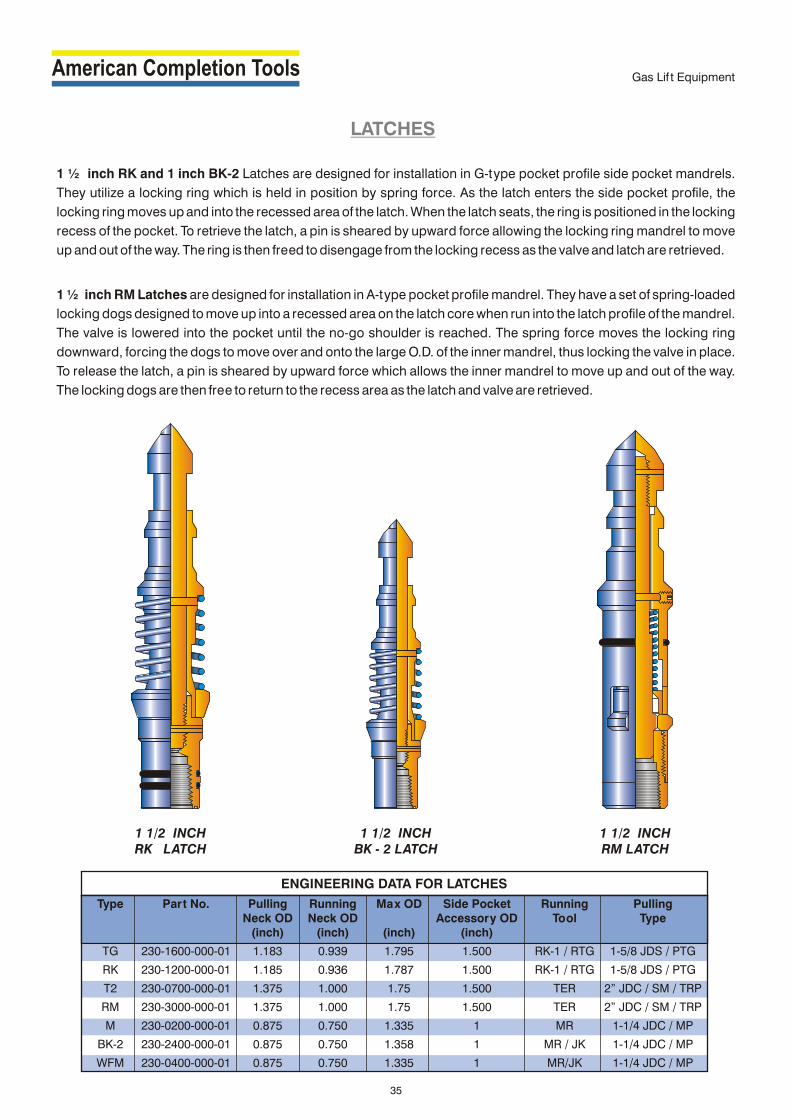
LATCHES
1 ½ inch RK and 1 inch BK-2 Latches are designed for installation in G-type pocket profile side pocket mandrels.
They utilize a locking ring which is held in position by spring force. As the latch enters the side pocket profile, the
locking ring moves up and into the recessed area of the latch. When the latch seats, the ring is positioned in the locking
recess of the pocket. To retrieve the latch, a pin is sheared by upward force allowing the locking ring mandrel to move
up and out of the way. The ring is then freed to disengage from the locking recess as the valve and latch are retrieved.
1 ½ inch RM Latches are designed for installation in A-type pocket profile mandrel. They have a set of spring-loaded
locking dogs designed to move up into a recessed area on the latch core when run into the latch profile of the mandrel.
The valve is lowered into the pocket until the no-go shoulder is reached. The spring force moves the locking ring
downward, forcing the dogs to move over and onto the large O.D. of the inner mandrel, thus locking the valve in place.
To release the latch, a pin is sheared by upward force which allows the inner mandrel to move up and out of the way.
The locking dogs are then free to return to the recess area as the latch and valve are retrieved.
1 1/2 INCHRK LATCH
1 1/2 INCHBK - 2 LATCH
1 1/2 INCHRM LATCH
Type Part No. Pulling Running Max OD Side Pocket Running PullingNeck OD Neck OD Accessory OD Tool Type
(inch) (inch) (inch) (inch)
TG 230-1600-000-01 1.183 0.939 1.795 1.500 RK-1 / RTG 1-5/8 JDS / PTG
RK 230-1200-000-01 1.185 0.936 1.787 1.500 RK-1 / RTG 1-5/8 JDS / PTG
T2 230-0700-000-01 1.375 1.000 1.75 1.500 TER 2” JDC / SM / TRP
RM 230-3000-000-01 1.375 1.000 1.75 1.500 TER 2” JDC / SM / TRP
M 230-0200-000-01 0.875 0.750 1.335 1 MR 1-1/4 JDC / MP
BK-2 230-2400-000-01 0.875 0.750 1.358 1 MR / JK 1-1/4 JDC / MP
WFM 230-0400-000-01 0.875 0.750 1.335 1 MR/JK 1-1/4 JDC / MP
ENGINEERING DATA FOR LATCHES
Gas Lif t Equipment
35
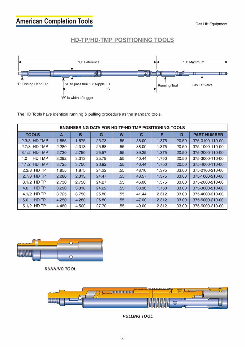
HD-TP/HD-TMP POSITIONING TOOLS
The HD Tools have identical running & pulling procedure as the standard tools.
“C” Reference “D” Maximum
Running Tool Gas Lif t Valve“A” to pass thru “B” Nipple I.D.
G
“W” is width of trigger
“F” Fishing Head Dia.
TOOLS A B G W C F D PART NUMBER
2.3/8 HD TMP 1.855 1.875 25.73 .55 38.00 1.375 20.50 375-0100-110-00
2.7/8 HD TMP 2.280 2.313 25.88 .55 38.00 1.375 20.50 375-1000-110-00
3.1/2 HD TMP 2.730 2.750 25.57 .55 39.25 1.375 20.50 375-2000-110-00
4.0 HD TMP 3.292 3.313 25.79 .55 40.44 1.750 20.50 375-3000-110-00
4.1/2 HD TMP 3.725 3.750 26.82 .55 40.44 1.750 20.50 375-4000-110-00
2.3/8 HD TP 1.855 1.875 24.22 .55 48.10 1.375 33.00 375-0100-210-00
2.7/8 HD TP 2.280 2.313 24.47 .55 48.57 1.375 33.00 375-1000-210-00
3.1/2 HD TP 2.730 2.750 24.27 .55 46.00 1.375 33.00 375-2000-210-00
4.0 HD TP 3.290 3.310 24.22 .55 38.96 1.750 33.00 375-3000-210-00
4.1/2 HD TP 3.725 3.750 25.80 .55 41.44 2.312 33.00 375-4000-210-00
5.0 HD TP 4.250 4.280 25.80 .55 47.00 2.312 33.00 375-5000-210-00
5.1/2 HD TP 4.480 4.500 27.70 .55 49.00 2.312 33.00 375-6000-210-00
ENGINEERING DATA FOR HD-TP/HD-TMP POSITIONING TOOLS
Gas Lif t Equipment
RUNNING TOOL
PULLING TOOL
36

SLIP LOCKASSEMBLY
SLIP LOCK ASSEMBLY
Applications
ACT Slip Lock Assembly is run to lock downhole controls in tubing string run without landing
nipple. The Slip Lock can be set at any department in the tubing.
Advantages
Run in tubing string without landing nipple
Operator can set the lock at any desired depth in the tubing
!
!
!
Tubing O.D O.D Min. Fishing Running Pulling Thread
O.D Slips Slips I.D. Neck Tool Tool Connection
Expand Retract
2.375” 2.062” 1.859” 0.687” 1.375” 41 WO 13 40 RB 17 1 3/16 x 14
2.875” 2.530” 2.296” 0.875” 1.750” 41 WO 14 40 RB 18 1 9/16 x 12
3.500” 3.080” 2.843” 1.375” 2.312” 41 WO 22 40 RB 19 2 x 12
4.500” 3.500” 3.281” 1.750” 2.750” 41 WO 30 40 RB 30 2 1/4 x 12
SURGE TOOL ASSEMBLY
Applications
ACT formation Surge Tool is to be assembled with relevant lock / equalizing
assembly. The assembly is to be run in well bore in normal manner and
device located in relevant nipple. The running tool is to be retrieved prior to
utilizing formation surge tool.
Advantages
Designed to allow draw-down to be created across the perforations in order
to remove debris
Can be retrieved by conventional wireline operations, af ter well pressure is
stabilized.
!
!
!
Tubing Weight Surge Surge Length
Size Tool O.D. Tool O.D.
2 3/8” 4.7 1.750” 0.885” 14.25”
2 7/8” 6.5 2.150” 1.096” 15.50”
3 1/2” 9.3 2.604” 1.315” 16.00”
SURGE TOOL ASSEMBLY
37
Downhole Flow Control

ACT TUBING PACK-OFF ANCHOR ASSEMBLY
These anchors are designed to be set anywhere in the tubing string to straddle and pack-of f holes or other
communication in the tubing string, so that well production can be continued without pulling tubing. Tubing pack-of f
anchors are run and set by wireline methods.
38
ACT TUBING PACK-OFF ANCHOR ASSEMBLY
Downhole Flow Control

TERMS & CONDITIONS
DESIGN: ACT reserves the right to make changes in design without notice.
CANCELLATION: Orders accepted by ACT are not subject to cancellation by customer except with the consent of ACT
and upon terms which will indemnify ACT against loss or damage occasioned by such cancellation.
INSPECTION: Final inspection and acceptance of products must be made at the ACT plant and shall be conclusive
except as regards latent defects. Customer's representatives may inspect at the plant during business hours prior to
shipment in such manner as will not inter fere with operation.
ENGINEERING AND SERVICE: Upon request, ACT may provide engineering and/or technical information about its
products and their uses and if feasible may provide personnel to assist purchase in ef fecting field installation and/or
field service, or assistance so provided, whether with or without charges, shall be advisory only, and purchaser agrees
to hold ACT harmless from claims for loss from any cause resulting from such advisory or service activity.
WARRANTY: THIS WARRANTY IS IN LIEU OF ALL OTHER WARRANTIES, EXPRESSED OR IMPLIED, INCLUDING
ANY IMPLIED WARRANTY OF MERCHANTABILITY OF FITNESS. ACT warrants that all products manufactured by it
shall be free of defects in workmanship and material when these products are used within the service and pressure
range for which they were manufactured. Such warranty shall be binding upon ACT for a period of one year from and
af ter shipment of such product. If at any time within such period, it is established to the satisfaction of ACT that any
product manufactured by ACT was defective at time the of shipment, ACT at its option, shall repair or replace such
items F. O.B. place of manufacture or other designated shipping point, or refund the purchase price paid. It is
understood that the liability of ACT shall be limited to such repair or replacement and that ACT SHALL NOT BE LIABLE
FOR ANY DIRECT, INDIRECT, INCIDENTAL OR CONSEQUENTIAL DAMAGES ARISING OUT OF ANY OBJECTS OR
FROM ANY CAUSE WHATSOEVER. This warranty does not cover deterioration by corrosion, including stress
corrosion or aging of non-metallic parts, or any other cause of failure other than defects in workmanship and material.
Any part or equipment which ACT does not manufacture shall be subject only to the warranties of ACT's vendors.
Unless repairs to, alterations of, or work done on said product by the purchaser shall be specifically authorised in
writing by ACT, any warranty applicable thereto shall become null and void.
LIABILITY CONSIDERATION: Purchaser will indemnify and hold ACT harmless from all claims including but not
limited to subsurface damage and surface damages arising from subsurface damage, including damage to
underground mineral pools reservoirs, equipment, deposits, or waste on such deposits, whether owned by purchaser
or a third party, resulting from performance of this contract, whether or not due to ACT's negligence.
39
Related Documents