ACSS for Paralleled Multi-Inverter Systems with DSP-Based Robust Controls YU-KAI CHEN, Member, IEEE National Huwei Institute of Technology Taiwan YU-EN WU TSAI-FU WU, Senior Member, IEEE CHUNG-PING KU National Chung Cheng University Taiwan An averaged current-sharing strategy (ACSS) for paralleled multi-inverter systems with digital signal processor (DSP)-based robust controls is presented. With an ACSS, the inverters are in parallel operation and each inverter has a voltage robust controller to achieve system stability and robustness, and a current robust controller to track the averaged inductor current of the inverters to achieve equal current distribution. In the proposed system, the current-sharing control loop is independent of the voltage control loop. Therefore, equal current distribution among the inverters, fast response, and tight regulation can be achieved. Additionally, the ACSS in each inverter can be readily implemented with two operational amplifiers. Simulation results and hardware measurements of a single-inverter system and a two-inverter system, and simulation results of a three-inverter system with linear and nonlinear loads have demonstrated the feasibility of the proposed control scheme in equal current distribution and fast regulation. Manuscript received August 6, 2002; revised February 10, 2003; released for publication March 31, 2003. IEEE Log No. T-AES/39/3/818506. Refereeing of this contribution was handled by W. M. Polivka. This work was supported by the National Science Council, Taiwan, under Project NSC 89-2213-E-270-027. Authors’ current addresses: Y-K. Chen, Dept. of Aeronautical Engineering, National Huwei Institute of Technology, 64 Wenhwa Road, Huwei Jen, Yunlin, Taiwan, 632 ROC; Y-E. Wu, Dept. of Electrical Engineering, Wu-Feng Institute of Technology, Ming-Hsiung, Chia-Yi, Taiwan, ROC; T-F. Wu, Power Electronics Applied Research Laboratory (PEARL), Dept. of Electrical Engineering, National Chung Cheng University, Ming-Hsiung, Chia-Yi, Taiwan, ROC, E-mail: ([email protected]); C-P. Ku, Industrial Technology Research Institute, Taiwan, ROC. 0018-9251/03/$17.00 c 2003 IEEE I. INTRODUCTION In recent years, sinusoidal pulsewidth modulated (SPWM) inverters have found their wide applications in various types of ac power conditioning systems, such as automatic voltage regulators (AVR), uninterruptible power supplies (UPS), active power filters (APF), etc. Parallel operation of inverters to obtain a larger power capacity and to improve system reliability becomes the trend of power system design. Two or more inverters operating in parallel must achieve the following features: 1) same amplitude, frequency and phase among the output voltages of inverters, 2) proper current distribution among inverters according to their capacities, 3) flexibility in paralleling any number of inverters, and 4) hot-swap feature at any operating time. To achieve the above features, there were several types of control strategies proposed in literature [1–11]. In [1], phase-locked loop (PLL) control technique was used to synchronize the output voltage of inverters. One of the most common methods for load current-sharing control is instantaneous modulation control, such as the master-slave control (MSC) and the highest current control (HCC) [6, 11]. In a system with the MSC [6], the master module is responsible for output voltage regulation, while the slave ones track the current command provided by the master to achieve an equal current distribution. In such a system, if the master module fails, the system will shut down. This is a major drawback. In [11], the proposed instantaneous voltage and current controller for the paralleled inverters with an HCC can quickly eliminate the current deviation and can achieve power balance among inverters. However, since the sensed highest output current would be noisy, the performance of current distribution and output voltage regulation will be deteriorated. In addition, the paralleled inverters with nonidentical component characteristics and input voltage variation will affect the models of the inverters and might also deteriorate in system performance. Therefore, robust controllers are adopted to achieve the robustness of the proposed paralleled multi-inverter system. In this paper, a voltage H robust controller is adopted to reduce the prementioned effects and to achieve the system stability and robustness; thus, the output voltage can be well regulated. In addition, an averaged current-sharing strategy (ACSS) is used to replace the HCC proposed in [11] to achieve an equal current distribution and to reduce noise effect occurring at inverter switching transition. Section II presents the system configuration of a paralleled multi-inverter system. In Section III, analysis and design of robust controllers are described and discussed in detail. A single-inverter 1002 IEEE TRANSACTIONS ON AEROSPACE AND ELECTRONIC SYSTEMS VOL. 39, NO. 3 JULY 2003

Welcome message from author
This document is posted to help you gain knowledge. Please leave a comment to let me know what you think about it! Share it to your friends and learn new things together.
Transcript

ACSS for ParalleledMulti-Inverter Systems withDSP-Based Robust Controls
YU-KAI CHEN, Member, IEEENational Huwei Institute of TechnologyTaiwan
YU-EN WU
TSAI-FU WU, Senior Member, IEEE
CHUNG-PING KUNational Chung Cheng UniversityTaiwan
An averaged current-sharing strategy (ACSS) for paralleledmulti-inverter systems with digital signal processor (DSP)-basedrobust controls is presented. With an ACSS, the inverters arein parallel operation and each inverter has a voltage robustcontroller to achieve system stability and robustness, and acurrent robust controller to track the averaged inductor currentof the inverters to achieve equal current distribution. In theproposed system, the current-sharing control loop is independentof the voltage control loop. Therefore, equal current distributionamong the inverters, fast response, and tight regulation can beachieved. Additionally, the ACSS in each inverter can be readilyimplemented with two operational amplifiers. Simulation resultsand hardware measurements of a single-inverter system and atwo-inverter system, and simulation results of a three-invertersystem with linear and nonlinear loads have demonstrated thefeasibility of the proposed control scheme in equal currentdistribution and fast regulation.
Manuscript received August 6, 2002; revised February 10, 2003;released for publication March 31, 2003.
IEEE Log No. T-AES/39/3/818506.
Refereeing of this contribution was handled by W. M. Polivka.
This work was supported by the National Science Council, Taiwan,under Project NSC 89-2213-E-270-027.
Authors’ current addresses: Y-K. Chen, Dept. of AeronauticalEngineering, National Huwei Institute of Technology, 64 WenhwaRoad, Huwei Jen, Yunlin, Taiwan, 632 ROC; Y-E. Wu, Dept.of Electrical Engineering, Wu-Feng Institute of Technology,Ming-Hsiung, Chia-Yi, Taiwan, ROC; T-F. Wu, Power ElectronicsApplied Research Laboratory (PEARL), Dept. of ElectricalEngineering, National Chung Cheng University, Ming-Hsiung,Chia-Yi, Taiwan, ROC, E-mail: ([email protected]); C-P. Ku,Industrial Technology Research Institute, Taiwan, ROC.
0018-9251/03/$17.00 c 2003 IEEE
I. INTRODUCTION
In recent years, sinusoidal pulsewidth modulated(SPWM) inverters have found their wide applicationsin various types of ac power conditioning systems,such as automatic voltage regulators (AVR),uninterruptible power supplies (UPS), active powerfilters (APF), etc. Parallel operation of inverters toobtain a larger power capacity and to improve systemreliability becomes the trend of power system design.Two or more inverters operating in parallel mustachieve the following features:
1) same amplitude, frequency and phase amongthe output voltages of inverters,
2) proper current distribution among invertersaccording to their capacities,
3) flexibility in paralleling any number ofinverters, and
4) hot-swap feature at any operating time.To achieve the above features, there were several
types of control strategies proposed in literature[1–11]. In [1], phase-locked loop (PLL) controltechnique was used to synchronize the output voltageof inverters. One of the most common methodsfor load current-sharing control is instantaneousmodulation control, such as the master-slave control(MSC) and the highest current control (HCC) [6, 11].In a system with the MSC [6], the master module isresponsible for output voltage regulation, while theslave ones track the current command provided bythe master to achieve an equal current distribution.In such a system, if the master module fails, thesystem will shut down. This is a major drawback. In[11], the proposed instantaneous voltage and currentcontroller for the paralleled inverters with an HCCcan quickly eliminate the current deviation and canachieve power balance among inverters. However,since the sensed highest output current would benoisy, the performance of current distribution andoutput voltage regulation will be deteriorated. Inaddition, the paralleled inverters with nonidenticalcomponent characteristics and input voltage variationwill affect the models of the inverters and might alsodeteriorate in system performance. Therefore, robustcontrollers are adopted to achieve the robustness ofthe proposed paralleled multi-inverter system.
In this paper, a voltage H robust controller isadopted to reduce the prementioned effects and toachieve the system stability and robustness; thus, theoutput voltage can be well regulated. In addition, anaveraged current-sharing strategy (ACSS) is usedto replace the HCC proposed in [11] to achieve anequal current distribution and to reduce noise effectoccurring at inverter switching transition.
Section II presents the system configurationof a paralleled multi-inverter system. In SectionIII, analysis and design of robust controllers aredescribed and discussed in detail. A single-inverter
1002 IEEE TRANSACTIONS ON AEROSPACE AND ELECTRONIC SYSTEMS VOL. 39, NO. 3 JULY 2003

system, a two-inverter system, and a three-invertersystem are presented in Section IV to verify thetheoretical discussion. Brief conclusions are presentedin Section V.
II. CONFIGURATION OF PARALLELEDMULTI-INVERTER SYSTEM
A paralleled multi-inverter system with theproposed ACSS can be conceptually illustrated byFig. 1(a), in which a schematic diagram of eachinverter associated with a digital signal processor(DSP) controller and the current-sharing center aredepicted in Fig. 1(b) and (c), respectively. With theACSS, the inductor current of each inverter is sensedas the input of the current-sharing center and thenthe averaged current iave of the paralleled n-invertersystem can be obtained. In the system, all the invertersare with the same configuration, and each inverter,as shown in Fig. 1(b), consists of a half-bridgeswitch configuration and an L-C output filter. Thecurrent-sharing center consists of scaling circuits andinverted circuits which are realized with operationalamplifiers, as shown in Fig. 1(c). The averagedcurrent iave is selected as the current command foreach inverter to achieve an equal current distribution.The DSP controller performs digital control andgenerates SPWM driving signals for switchingdevices, in which a clock rate of 20 MHz and 10 bitanalog-to-digital (A/D) converters (for feeding backinductor current and output voltage) are adopted. Inthe proposed system, the voltage H robust controlleris responsible for output voltage regulation, while thecurrent ones will track the current command iave toachieve an equal current distribution. The proposedcontrol scheme is realized with a TMS320F240 DSPchip.
III. ANALYSIS AND DESIGN OF ROBUSTCONTROLLERS
Each inverter with the ACSS includes twocontrollers: one is for output voltage loop; the otheris for current-sharing loop. The H robust controltechnique is adopted to design these controllersfor achieving equal current distribution, low outputvoltage distortion, and low steady-state error. Beforeperforming these designs, the dynamics of theinverters needs to be analyzed.
A. Modeling of Single-Inverter System
To design a proper controller for an SPWMcontrolled inverter, the dynamics of a single-invertersystem is modeled and illustrated by a control blockdiagram shown in Fig. 2, where vref is the perturbationof a sinusoidal reference voltage, vo is the perturbationof the output voltage, vfb is the perturbation of the
Fig. 1. (a) Block diagram of paralleled multi-inverter system.(b) Circuit diagram of single-inverter system. (c) Circuit diagram
of current-sharing center for proposed ACSS.
Fig. 2. Control block diagram of single-inverter system.
feedback voltage, io is the perturbation of the outputcurrent, d is the perturbation of the duty cycle, vcis the perturbation of control voltage, and Kv(s) isan output voltage-loop controller. Hv represents the
CHEN ET AL.: ACSS FOR PARALLELED MULTI-INVERTER SYSTEMS WITH DSP-BASED ROBUST CONTROLS 1003

Fig. 3. Bode plot of control-to-output voltage transfer function under three different load conditions.
feedback gain and KPWM is the pulsewidth modulated(PWM) gain of the inverter. Effective series resistanceof the capacitor and inductor are neglected. Thesmall-signal control-to-output voltage transfer function(vo=vc) of a single-inverter system then can be derivedwith the Mason’s rule and expressed as follows:
GV(s) =vovc=
KPWM (Lls+Rl)[LLlCs3 +RlLCs2 + (L+Ll)s+Rl]
(1)
where Rl and Ll are load resistance and inductance.A detailed derivation of (1) is given in Appendix A.Fig. 3 shows the plots of control-to-output voltagetransfer function versus frequency under threedifferent load conditions (no load, a 0.7 laggingload, and full load). Note that as shown in Fig. 3,the voltage loop small-signal transfer functions ofthe single-inverter system are different under differentload conditions. Thus, variation of loads is treated asan uncertainty of the proposed system. In addition,variations of input voltage and component valuesare also treated as uncertainties of the single-invertersystem in the design.
B. Design of Voltage Robust Controller
It can be observed from Fig. 3 that outputvoltage-loop transfer characteristics vary withloads, input voltages, and component values in asingle-inverter system. To reduce the effects due tothe variations, the H robust control technique isadopted to design an output voltage controller. Ablock diagram used to illustrate the proposed Hrobust control is depicted in Fig. 4, in which themultiplicative uncertainty-plant ¢G(s) is with threeuncertainties, including variations of component
Fig. 4. Illustration of augmented plant with robust controllerK(s).
values, load, and input voltage. The design procedureof a robust controller is outlined as follows.
1) Augment the plant Gv(s) (= vo=vc) withweighting functions W1(s) and W2(s) based on thedesired performance indices. The augmented plantP(s) can be conceptually illustrated by Fig. 4.Generally, weighting function W1(s) is a typicallow-pass filter, shaping the sensitivity function S atlow frequency to reject disturbance and to reducetracking errors, and Z1 is a control variable usedto adjust the tracking errors. Weighting functionW2(s) is chosen to be a high-pass filter, shapingthe complementary sensitivity function T at highfrequency to minimize instability effects.
2) First consider sinusoidal inputs and suppose thatinput r can be any sinusoidal signal with amplitude 1and we want tracking error e to have amplitude < ".Then the performance specification can be expressedsuccinctly as
S < ": (2)
That is, the maximum amplitude of error e equalsthe -norm of the transfer function S. In severalapplications, for example aircraft flight-control design,designers have acquired through experience thedesired shapes for the Bode magnitude plot of S. Inparticular, suppose that good performance is known
1004 IEEE TRANSACTIONS ON AEROSPACE AND ELECTRONIC SYSTEMS VOL. 39, NO. 3 JULY 2003

to be achieved if the plot of S(j!) lies under somecurve. We can rewrite this as
S(j!) < W1(j!)1, !: (3)
Or,W1S < 1: (4)
Additionally, for the multiplicative uncertainty model(1+¢W2)GK , if
W2T < 1 (5)
this implies
¢W2T < W2T < 1: (6)
Then, we have
1+ (1+¢W2)GK = (1+GK) 1+¢W2GK
1+GK
= (1+GK)(1+¢W2T) 1+GK
(7)
that is, the perturbation ¢W2 does not change thestability condition, achieving robustness. Rigorousproof of the prementioned inequalities can be foundfrom [12, 13]. Next, we have to find an H robustcontroller K(s) to satisfy the following inequality:
W1S
W2T1 (8)
where S(s) = (I+G(s)K(s)) 1 is the sensitivityfunction and T(s) =G(s)K(s)(I+G(s)K(s)) 1 isthe closed-loop transfer function of the referencecommand vref to the measured output vo. T(s) is alsocalled a complementary sensitivity function.3) Verify if the design is close to the desired
performance indexes based on the evaluation of thesingular-value Bode plot. If it is not, we need togo back to step 1 to select another set of weightingfunctions and go through all steps again.
C. Modeling of Paralleled Current-SharingMulti-Inverter System
To investigate the current distribution amonginverters, a multi-inverter system is designed with theinverters in parallel connection and each inverter has acurrent robust controller to track the averaged inductorcurrent iave to achieve an equal current distribution.A control block diagram of the proposed system withthe ACSS is shown in Fig. 5. The control-to-inductorcurrent transfer function (iL=vci) of the inverter systemfor inductive load is derived with the Mason’s ruleand represented as follows:
Gi(s) =iLvci=
KPWM (s2LlC+ sCRl)s3LLlC+ s2LCRl + sLl + sL+Rl
: (9)
Fig. 5. System configuration of proposed paralleled multi-invertersystem with ACSS.
From (9), it can be observed that the control-to-inductor current transfer function of an inverter varieswith component values.
D. Design of Current Robust Controller
Design of a current robust controller for acurrent-sharing loop is the same as that of a voltagerobust controller, which has been shown in SubsectionB of this section.
IV. ILLUSTRATION EXAMPLES AND DISCUSSION
Three examples, single-inverter, two-inverter, andthree-inverter systems, with current and voltage Hrobust controllers are used to illustrate the previousdiscussion. The design specifications of the aboveexamples are given as follows.
A. Output Voltage Loop
1) phase margin (PM) 60 and gain margin(GM) 40 dB,
2) bandwidth 3 kHz,3) steady-state error = 0,4) minimizing the sensitivity to the variations of
input voltage, component value, and load condition.
CHEN ET AL.: ACSS FOR PARALLELED MULTI-INVERTER SYSTEMS WITH DSP-BASED ROBUST CONTROLS 1005

Fig. 6. Magnitude plot of weighting function W2(s) and multiplicative uncertainty-plant.
Fig. 7. Bode plot of sixth-order and second-order robust controllers.
B. Current-Sharing Loop
1) PM 60 and GM 40 dB,2) bandwidth 3 kHz,3) steady-state error = 0,4) minimizing the sensitivity to the variations of
input voltage and component value.
EXAMPLE 1 Single-Inverter System: The electricalspecifications and component values of a singleinverter are collected in Table I. For the outputvoltage loop, weighting functions W1(s) and W2(s) aredetermined to satisfy all aforementioned specificationssimultaneously and to ensure robust stability.Typically, the weighting functions W1(s) and W2(s) arechosen as follows:
W1(s) = K1
s
!C+1
s+10 6
n1
(10)
TABLE ISpecifications and Component Values of Single-Inverter System
and
W2(s) =
s
!C+1
(10 6s+1)
n2
(11)
where K1 is used to adjust the tracking error, bothn1 and n2 are either 1 or 2, and wC and wC are the
1006 IEEE TRANSACTIONS ON AEROSPACE AND ELECTRONIC SYSTEMS VOL. 39, NO. 3 JULY 2003

Fig. 8. Bode plot of loop gain in voltage-regulation loop with designed robust controller.
Fig. 9. Output voltage and current waveforms of single-inverter system operating with pure resistant load. (a) Simulation.(b) Measurement.
CHEN ET AL.: ACSS FOR PARALLELED MULTI-INVERTER SYSTEMS WITH DSP-BASED ROBUST CONTROLS 1007

Fig. 10. Output voltage and current waveforms of single-inverter system operating with high CF load. (a) Simulation. (b) Measurement.
two parameters used to adjust the bandwidth of theclosed-loop system. For good tracking performance,sensitivity function S(s) should generally exhibitlow-gain property over low frequency range. SinceW1S < 1, W1(s) must behave as a low-pass filter.The multiplicative uncertainty-plant ¢G(s) of thesingle-inverter system includes the variations ofinput voltage, component value, and load condition.As to the choice of W2(s) for system robustness,the magnitude of W2(s) should be large enough toaccommodate the multiplicative uncertainty-plant,as illustrated in Fig. 6. Similarly, high-pass propertyof W2(s) is required to achieve enough bandwidthfor the closed-loop transfer function T(s) becauseW2T < 1.The weighting functions Wv1(s) and Wv2(s) of the
output-voltage loop are selected as
Wv1(s) =300
s
3000+1
s+10 6 (12)
and
Wv2(s) =1:5
s
3000+1
2
(s+10 6)2: (13)
The 6th order H robust controller KV6(s) can bederived with MATLAB Robust Control Toolbox.Through a minimal realization, which is the realizationof a model with the redundant or unnecessary stateseliminated, a second-order robust controller can beobtained as follows:
KV(s) =104 (1:81 10 7s2 +7:89 10 4s+7:64)
10 7s2 + 5:95s+1:98 10 3 :
(14)The Bode plots of KV6(s) and KV(s) are plotted inFig. 7. From the figure, we can observe that thecharacteristic of KV6(s) is nearly the same as that ofKV(s) from dc to 3 kHz of the desired bandwidth.Fig. 8 shows the Bode plot of the loop gain inthe voltage-regulation loop; we can see that thespecifications of the system are achieved with the
1008 IEEE TRANSACTIONS ON AEROSPACE AND ELECTRONIC SYSTEMS VOL. 39, NO. 3 JULY 2003

Fig. 11. Transient responses of output voltage and current to step load change from 33% to 100% of full load. (a) Simulation.(b) Measurement.
designed controller. In simulation, the controlleris realized with analog circuits, while in hardwareimplementation, they are first converted to discreteforms with the bilinear transformation, which mapsthe s-plane into the z-plane. The designed controller isrepresented in difference equations as shown in (15),and it is programmed on a TMS 320F240 DSP chip[14].
YÀ(K) = 107 [2:967UÀ(K) +5:934UÀ(K 1)
+ 2:967UÀ(K 2)]
1:5379YÀ(K 1) 0:5379YÀ(K 2)
(15)
where YÀ(K) is the output of the voltage controller andUÀ(K) is the input of the voltage controller. Simulatedand measured results of such a system loaded with aresistor are shown in Fig. 9, where the voltage andcurrent waveforms are sinusoidal and in phase.These results appear closely consistent with eachother.
Fig. 10 and Fig. 11 show the simulated andmeasured output current and voltage responses ofsuch a system with a high crest factor load (CF = 3)and with a step load change from 33% to 100%,respectively. It can be observed from the waveformsthat fast regulation can be achieved. Total harmonicdistortion (THD) and odd harmonics of the outputvoltage of the system operated with a full linear loadand a high CF load are listed in Tables II and III,respectively.
EXAMPLE 2 Two-Inverter System: To investigate thecurrent distribution between inverters, a two-invertersystem with the circuit parameters collectedin Table IV is simulated and implemented. Asdescribed previously, the robust current-sharingcontrol technique has been adopted to deal with theuncertainty between the paralleled inverters. Thus, thevoltage controller of example 1 can also be used inthis inverter.
With the design specifications of current-sharingloop, the weighting functions Wi1(s) and Wi2(s) of the
CHEN ET AL.: ACSS FOR PARALLELED MULTI-INVERTER SYSTEMS WITH DSP-BASED ROBUST CONTROLS 1009
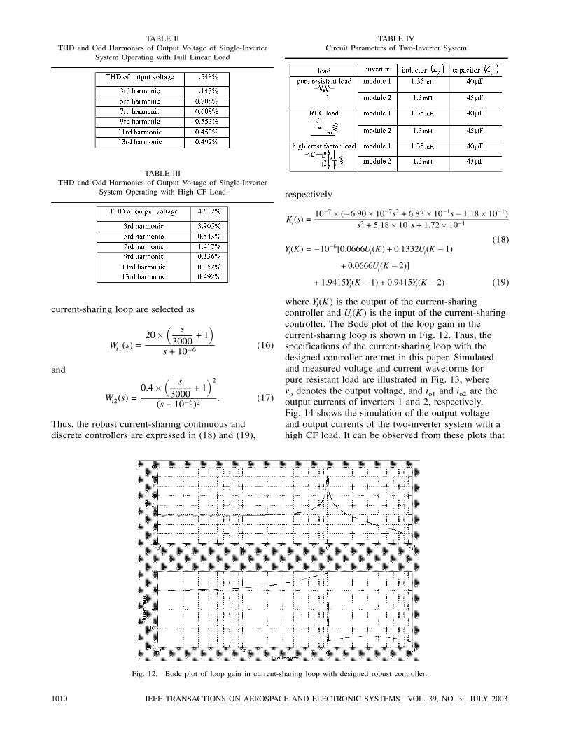
TABLE IITHD and Odd Harmonics of Output Voltage of Single-Inverter
System Operating with Full Linear Load
TABLE IIITHD and Odd Harmonics of Output Voltage of Single-Inverter
System Operating with High CF Load
current-sharing loop are selected as
Wi1(s) =20
s
3000+1
s+10 6 (16)
and
Wi2(s) =0:4
s
3000+1
2
(s+10 6)2: (17)
Thus, the robust current-sharing continuous anddiscrete controllers are expressed in (18) and (19),
Fig. 12. Bode plot of loop gain in current-sharing loop with designed robust controller.
TABLE IVCircuit Parameters of Two-Inverter System
respectively
Ki(s) =10 7 ( 6:90 10 7s2 + 6:83 10 1s 1:18 10 1)
s2 + 5:18 101s+1:72 10 1
(18)Yi(K) = 10 6[0:0666Ui(K) +0:1332Ui(K 1)
+0:0666Ui(K 2)]
+ 1:9415Yi(K 1)+0:9415Yi(K 2) (19)
where Yi(K) is the output of the current-sharingcontroller and Ui(K) is the input of the current-sharingcontroller. The Bode plot of the loop gain in thecurrent-sharing loop is shown in Fig. 12. Thus, thespecifications of the current-sharing loop with thedesigned controller are met in this paper. Simulatedand measured voltage and current waveforms forpure resistant load are illustrated in Fig. 13, wherevo denotes the output voltage, and io1 and io2 are theoutput currents of inverters 1 and 2, respectively.Fig. 14 shows the simulation of the output voltageand output currents of the two-inverter system with ahigh CF load. It can be observed from these plots that
1010 IEEE TRANSACTIONS ON AEROSPACE AND ELECTRONIC SYSTEMS VOL. 39, NO. 3 JULY 2003

Fig. 13. Output voltage and current waveforms of two-inverter system with pure resistant load. (a) Simulation. (b) Measurement.
Fig. 14. Simulated output voltage and current waveforms of two-inverter system with high CF load.
equal current distribution can be achieved regardlessof the types of loads and component discrepancybetween inverters.
EXAMPLE 3 Three-Inverter System: For furtherverifying the feasibility of the proposed ACSS,a three-inverter system with a pure resistant load
CHEN ET AL.: ACSS FOR PARALLELED MULTI-INVERTER SYSTEMS WITH DSP-BASED ROBUST CONTROLS 1011
Fig. 15. Simulated output voltage and current waveforms of three-inverter system with (a) inverter 3 in failure, and (b) inverter 3connected to load.
is simulated, whose results are plotted in Fig. 15.The three output currents are tracking each otherprecisely and the output voltage waveform sustainssinusoidal. Moreover, in order to investigate thesystem reliability, the system with ACSS underthe case of one inverter in open-circuit failure orshort-circuit failure is presented. Fig. 15(a) showsthe waveforms of a system with inverter 3 in thesefailures. It can be seen that the output voltage andcurrent waveforms are sinusoidal and in phase withoutnoticeable variation under such a sudden failure, andthe other two inverters can continuously supply powerto the load. Fig. 15(b) shows a plot in which the loadis first supplied by inverter 1 and inverter 2, and theninverter 3 is synchronized and connected to the load.Again, it can be observed that the three inverters canshare output current equally and output voltage issinusoidal.The advantages of the paralleled multi-inverter
system with the robust ACSS are outlined asfollows.1) It can reduce the system uncertainties and
achieve system stability and robustness.
2) Each inverter module can be kept in the sameconfiguration in a paralleled inverter system with anynumber of inverters.
3) Even a single inverter can work with acurrent-sharing center because the gain of thecurrent-sharing center in a single-inverter system isunity.
4) A hot-swap feature of the paralleled system canbe achieved at any operating time.
5) Under any inverter failure, the system stillworks successfully.
6) Equal output current distribution among theinverters and fast output regulation can be achievedwhile component values, input voltages, and loadsmay vary over a wide range.
V. CONCLUSIONS
An ACSS for inverters in parallel operation toachieve equal current distribution has been studied.Each inverter in the proposed system consists of avoltage robust controller to achieve a fast dynamicresponse, and a current robust controller to reachsystem robustness and to reduce uncertainty among
1012 IEEE TRANSACTIONS ON AEROSPACE AND ELECTRONIC SYSTEMS VOL. 39, NO. 3 JULY 2003

Fig. 16. (a) Circuit diagram and (b) control block diagram ofoutput L-C filter and load.
inverters. It has been verified that a system withACSS can accommodate various types of loads andvariations of input voltage and component value.In other words, the proposed ACSS is with a tightcurrent tracking characteristic regardless of the typesof loads and discrepancy among inverters. In addition,flexibility and hot-swap feature can be achieved for asystem with various numbers of inverters.Simulation results have shown that fast dynamic
response, tight output regulation, and equal currentdistribution can be achieved in the proposed paralleledmulti-inverter systems. Hardware measurementsobtained from a laboratorious prototype have shownsimilar performance to those of the simulation resultsand have also verified the theoretical discussion.
APPENDIX A
The half-bridge inverter consists of a half-bridgeswitch configuration and an output L-C filter. Thehalf-bridge switch can be modeled as an amplifierwith gain KPWM, in which nonlinearity of PWMswitches is neglected. Additionally, a circuit diagramof an output L-C filter is shown in Fig. 16(a).Choosing capacitor voltage vc and inductor current iLas state variables, and PWM input d and load currentIo as inputs, the system dynamic equations can bederived as follows:
vi = LiL + rCiC + vC (20)
vc =1CiC (21)
andiC = iL Io: (22)
Or,
iL =rL + rCL
1LvC +
1Ld+
rCLIo (23)
and
vC =1CiL
1CIo: (24)
From the above equations, a block diagram of theoutput L-C filter can be represented in Fig. 16(b)and the closed-loop block diagram of the invertersystem can be represented in Fig. 2. Therefore, thecontrol-to-output voltage and control-to-inductorcurrent transfer functions, respectively represented in(1) and (9), can be derived with the Mason’s rule.
REFERENCES
[1] Dobrorolny, P., Woods, J., and Ziogas, P. D. (1989)A phase-locked-loop synchronization scheme for paralleloperation of modular power supplies.In Proceedings of the IEEE Power Electronics SpecialistsConference, 1989, 861–869.
[2] Chen, J-F., Chu, C-L., and Huang, O-L. (1992)The parallel operation of two UPS by thecoupled-inductor method.In Proceedings of the IEEE Industrial Electronics, Controland Instrumentation, 1992, 733–736.
[3] Fraser, M. E., and Manning, C. D. (1994)Performance of average current mode controlled PWMUPS factor load.In Proceedings of the IEEE Power Electronics andVariable-Speed Drives, 1994, 661–667.
[4] Tzou, Y-Y. (1995)DSP-based fully digital control of a PWM dc-ac converterfor ac voltage regulation.In Proceedings of the IEEE Power Electronics SpecialistsConference, 1995, 138–144.
[5] Ryan, M. J., and Lorenz, R. D. (1995)A high performance sine wave inverter controller withdecoupling.In Proceedings of the IEEE Power Electronics SpecialistsConference, 1995, 507–513.
[6] Chen, J-F., and Chu, C-L. (1995)Combination voltage-controlled and current-controlledPWM inverters for UPS parallel operation.IEEE Transactions on Power Electronics, 10, 5 (Sept.1995), 547–558.
[7] Tuladhar, A., Jin, H., Unger, T., and Mauch, K. (1997)Parallel operation of single phase inverter.In Proceedings of the IEEE Applied Power ElectronicsConference, 1997, 94–100.
[8] Kawabata, K., Sashida, N., Yamamoto, Y., Ogasawara, K.,and Yamasaki, Y. (1991)Parallel Processing Inverter System.IEEE Transactions on Power Electronics, 6, 3 (July 1991),442–450.
[9] Kawabata, T., and Higashino, S. (1988)Parallel operation of voltage source inverters.IEEE Transactions on Industry Applications, 24, 2(Mar./Apr. 1988), 281–287.
[10] Martins, A. P., Carvalho, A. S., and Araujo, A. S. (1995)Design and implementation of a current controller.In Proceedings of the IEEE Industrial Electronics, Controland Instrumentation, 1995, 584–589.
[11] Lee, C. S., et al. (1998)Parallel UPS with an instantaneous current sharingcontrol.In Proceedings of the IEEE Industrial Electronics, Controland Instrumentation, 1998, 568–573.
[12] Doyle, C., Francis, B. A., and Tannenbaum, A. R. (1992)Feedback Control Theory.New York: Maxwell Macmillan, 1992.
CHEN ET AL.: ACSS FOR PARALLELED MULTI-INVERTER SYSTEMS WITH DSP-BASED ROBUST CONTROLS 1013

[13] Grimble, M. J. (1994)Robust Industrial Control: Optimal Design Approach forPolynominal Systems.New York: Prentice Hall, 1994.
Yu-Kai Chen (S’98—M’99) was born in Chia-Yi, Taiwan, in 1967. He receivedthe B.S. degree in electronic engineering from Feng Chia University Tai-Chung,Taiwan and the M.S. degree in information and electronics engineering fromNational Central University, Chung-Li, Taiwan, and the Ph.D. degree in electricalengineering from National Chung Cheng University, Chia-Yi, Taiwan, in 1990,1994, and 1999, respectively.From 1994 to 1999, he was a Lecturer in the Department of Electronic
Engineering, Wu Feng Institute of Technology, Chia-Yi, Taiwan. He wasan associate professor in the Department of Electrical Engineering at ChienKuo Institute of Technology from 2000 to 2001. Since 2002, he has beenwith the Aeronautical Engineering, National Hu-wei Institute of Technology,Yun-lin, Taiwan, where he is currently an associate professor. His researchinterests include modeling and control of dc/dc converters, design of convertersand inverters, and design of solar-panel supplied systems, and DSP- andmicroprocessor-based application systems with fuzzy and robust control.
Yu-En Wu was born in Chia-Yi, Taiwan, in 1964. He received the B.S. degreein electrical engineering from Taiwan Institute of Technology, Taipei, Taiwan, in1989, and the M.S. degree in electrical engineering from Sun Yat-Sen University,Kaohsiung, Taiwan, in 1992.He is currently a Ph.D. candidate in the Department of Electrical Engineering,
National Chung Cheng University, Chia-Yi, Taiwan, and is also an instructor ofelectronic engineering at Wu-Feng Institute of Technology. His research interestsinclude modeling and control of converters, design of inverters, multi-invertersystem, and paralleling UPS system.
[14] Chen, C-T. (1993)Analog & Digital Control System Design:Transfer-function, State-space, & Algebraic Methods.New York: Oxford University, 1993.
1014 IEEE TRANSACTIONS ON AEROSPACE AND ELECTRONIC SYSTEMS VOL. 39, NO. 3 JULY 2003
Tsai-Fu Wu (S’89—M’91—SM’98) received the B.S. degree in electronicsengineering from National Chiao-Tung University, Taiwan, in 1983, the M.S.degree in electrical and computer engineering from Ohio University, Athens, in1988, and the Ph.D. degree in electrical engineering and computer science fromUniversity of Illinois at Chicago, in 1992.From 1985 to 1986 he was a system engineer at SAMPO, Inc., Taiwan,
developing and designing graphic terminals. He was a teaching and researchassistant in the Department of Electrical Engineering and Computer Science,University of Illinois, Chicago, from 1988 to 1992. Since 1993, he has beenwith the Electrical Engineering Department, National Chung Cheng University,Taiwan, where he is currently a professor, department head and the Directorof the Power Electronics Applied Research Laboratory (PEARL). His researchinterests include developing and modeling of power converters, design ofelectronic dimming ballasts for fluorescent lamps, metal halide lamps and plasmadisplay, and design of solar-panel-supplied inverters for grid connection.Dr. Wu is a Senior Member of the CIE.
Chung-Ping Ku was born in Kaohsiung, Taiwan, in 1977. He received the B.S.degree in electrical engineering from National Huwei Institute of Technology,Yulin, Taiwan, in 2000, and the M.S. degree from National Chung-ChengUniversity, Chia-Yi, Taiwan, in 2002.He currently joins Industrial Technology Research Institute, Taiwan, designing
power converter for the sulfur lamp system. His research interests include powerconverters, ballasts and microprocessor-based application systems.
CHEN ET AL.: ACSS FOR PARALLELED MULTI-INVERTER SYSTEMS WITH DSP-BASED ROBUST CONTROLS 1015
Related Documents