ACA 6xx Sections 3 to 4300 kW ACS 600 MultiDrive Safety and Product Information These Safety Instructions must be studied before storaging, installing, commissioning, servicing and operating the air-cooled ACS 600 MultiDrive frequency converters. This manual includes • Safety Instructions • Technical data

Welcome message from author
This document is posted to help you gain knowledge. Please leave a comment to let me know what you think about it! Share it to your friends and learn new things together.
Transcript

ACA 6xx Sections3 to 4300 kW
ACS 600 MultiDrive Safety and Product Information
These Safety Instructions must be studied before storaging, installing, commissioning, servicing and operating the air-cooled ACS 600 MultiDrive frequency converters.
This manual includes• Safety Instructions• Technical data

ACS 600 MultiDrive Manuals (Air-cooled Units, English Originals)
GENERAL MANUALS
*Safety and Product Information EN 63982229• Complete general Safety Instructions• Technical data for DSU and TSU supplies and Drive Sections: ratings,
power losses, dimensions, weights, fuses etc.
*System Description EN 63700151• General description of ACS 600 MultiDrive
*Hardware Manual EN 63700118• General Safety Instructions• Hardware description of the Drive Section• Cable selection• ACS 600 MultiDrive mechanical and electrical installation• Hardware commissioning of the Drive Section• Preventive maintenance of ACS 600 MultiDrive
ACS 600 MultiDrive Control Electronics LED Indicators EN 64289721• LED descriptions
**Modules Product Catalogue EN 64104268• Supply Unit components• Drive Unit components• Dynamic Braking Units• DriveWare information• Dimensional drawings• Single line diagrams• Auxiliary power consumption• Master component tables
**Modules Installation Manual EN 64119010• Cabinet assembly• Wiring
**Grounding and Cabling of the Drive System EN 61201998 • Grounding and cabling principles of a variable speed drive system
**EMC Compliant Installation and Configuration for a Power Drive System EN 61348280
* Included with cabinet-assembled systems only** Included in Modules deliveries only
SUPPLY SECTION MANUALS (depending on the supply type one of these manuals is included in the delivery)
Diode Supply Sections User’s Manual (DSU) EN 61451544• DSU specific Safety Instructions • DSU hardware and software descriptions• DSU commissioning• Earth fault protection options
Thyristor Supply Sections User’s Manual (TSU) EN 64170597• TSU operation basics• TSU firmware description• TSU program parameters• TSU commissioning
IGBT Supply Sections User’s Manual (ISU) EN 64013700• ISU specific Safety Instructions • Main components of ISU• ISU ratings• ISU power losses• ISU dimensions and weights• ISU fuses• ISU program parameters• Earth fault protection options
FIRMWARE MANUALS FOR DRIVE APPLICATION PROGRAMS (appropriate manual is included in the delivery)
System EN 63700177• Commissioning of the System Application Program• Control Panel use• Software description• Parameters of the System Application Program• Fault tracing• Terms
Application Program Template EN 63700185• Commissioning of the Drive Section• Control Panel use• Software description• Parameters • Fault tracing• Terms
Standard EN 61201441• Control Panel use• Standard application macros with external control connection diagrams• Parameters of the Standard Application Program• Fault tracing • Fieldbus controlNote: a separate Start-up Guide is attached
Crane Drive EN 3BSE 011179• Commissioning of the Crane Drive Application Program• Control Panel use• Crane program description• Parameters of the Crane Drive Application Program• Fault tracing
CONTROL SECTION MANUALS (delivered with optional Control Section)
Advant Controller 80 User’s Manual EN 64116487• AC 80 hardware and connections• AC 80 software• Programming• Diagnostics
Advant Controller 80 Reference Manual PC Elements EN 64021737• Description of PC and DB elements
Advant Controller 80 Reference Manual TC Elements EN 64331868• Description of TC elements
BRAKING SECTION MANUAL (delivered with optional Braking Section)
ACA 621/622 Braking Sections User’s Manual EN 64243811• Installation, Start-up, Fault tracing,Technical data• Dimensional drawings
MANUALS FOR OPTIONAL EQUIPMENT (delivered with optional equipment)
Fieldbus Adapters, I/O Extension Modules, Braking Choppers etc.• Installation• Programming• Fault tracing• Technical data

ACA 6xx Sections3 to 4300 kW
Safety and Product Information
3AFY 63982229 R0125 REV D
EFFECTIVE: 1.12.2000SUPERSEDES: 15.10.1999
� 2000 ABB Industry Oy. All Rights Reserved.


Table of Contents
ACS 600 MultiDrive Manuals (Air-cooled Units, English Originals)
Table of Contents
Safety Instructions
Overview . . . . . . . . . . . . . . . . . . . . . . . . . . . . . . . . . . . . . . . . . . . . . . . . . . . . . . . . . . . . . . . . . . . . . .1CAUTION! . . . . . . . . . . . . . . . . . . . . . . . . . . . . . . . . . . . . . . . . . . . . . . . . . . . . . . . . . . . . . . . . . . . 1Note: . . . . . . . . . . . . . . . . . . . . . . . . . . . . . . . . . . . . . . . . . . . . . . . . . . . . . . . . . . . . . . . . . . . . . . . 1
Operation . . . . . . . . . . . . . . . . . . . . . . . . . . . . . . . . . . . . . . . . . . . . . . . . . . . . . . . . . . . . . . . . . . . . . .1Installation and Maintenance Safety . . . . . . . . . . . . . . . . . . . . . . . . . . . . . . . . . . . . . . . . . . . . . . . . .2Starting TSU or DSU . . . . . . . . . . . . . . . . . . . . . . . . . . . . . . . . . . . . . . . . . . . . . . . . . . . . . . . . . . . . .4ACA 635 (ISU) Supply . . . . . . . . . . . . . . . . . . . . . . . . . . . . . . . . . . . . . . . . . . . . . . . . . . . . . . . . . . . .5Supply Connections . . . . . . . . . . . . . . . . . . . . . . . . . . . . . . . . . . . . . . . . . . . . . . . . . . . . . . . . . . . . . .5
Earth Fault Protective Function . . . . . . . . . . . . . . . . . . . . . . . . . . . . . . . . . . . . . . . . . . . . . . . . . . 6Emergency Stop Devices . . . . . . . . . . . . . . . . . . . . . . . . . . . . . . . . . . . . . . . . . . . . . . . . . . . . . . . . . .6
Immediate Removal of Power (Category 0) . . . . . . . . . . . . . . . . . . . . . . . . . . . . . . . . . . . . . . . . 7Controlled Emergency Stop (Category 1) . . . . . . . . . . . . . . . . . . . . . . . . . . . . . . . . . . . . . . . . . . . 7Restart . . . . . . . . . . . . . . . . . . . . . . . . . . . . . . . . . . . . . . . . . . . . . . . . . . . . . . . . . . . . . . . . . . . . . . 7
Prevention of Unexpected Start . . . . . . . . . . . . . . . . . . . . . . . . . . . . . . . . . . . . . . . . . . . . . . . . . . . . .7Motor Connections . . . . . . . . . . . . . . . . . . . . . . . . . . . . . . . . . . . . . . . . . . . . . . . . . . . . . . . . . . . . . . .8
Pulses in the Drive Output . . . . . . . . . . . . . . . . . . . . . . . . . . . . . . . . . . . . . . . . . . . . . . . . . . . . . . 8Power Factor Compensation Capacitors . . . . . . . . . . . . . . . . . . . . . . . . . . . . . . . . . . . . . . . . . . 12
Components Connected to Digital/Analogue Inputs . . . . . . . . . . . . . . . . . . . . . . . . . . . . . . . . . . . . .13EMC . . . . . . . . . . . . . . . . . . . . . . . . . . . . . . . . . . . . . . . . . . . . . . . . . . . . . . . . . . . . . . . . . . . . . . . . .13Fibre Optic Cables . . . . . . . . . . . . . . . . . . . . . . . . . . . . . . . . . . . . . . . . . . . . . . . . . . . . . . . . . . . . . .14Cooling . . . . . . . . . . . . . . . . . . . . . . . . . . . . . . . . . . . . . . . . . . . . . . . . . . . . . . . . . . . . . . . . . . . . . . .14Mechanical Installation . . . . . . . . . . . . . . . . . . . . . . . . . . . . . . . . . . . . . . . . . . . . . . . . . . . . . . . . . . .15
ACS 600 MultiDrive – Technical Data
Abbreviations . . . . . . . . . . . . . . . . . . . . . . . . . . . . . . . . . . . . . . . . . . . . . . . . . . . . . . . . . . . . . . . . . A-1Supply Section Tables . . . . . . . . . . . . . . . . . . . . . . . . . . . . . . . . . . . . . . . . . . . . . . . . . . . . . . . . . . A-2
Notes . . . . . . . . . . . . . . . . . . . . . . . . . . . . . . . . . . . . . . . . . . . . . . . . . . . . . . . . . . . . . . . . . . . . . A-2Ratings 380...415 V . . . . . . . . . . . . . . . . . . . . . . . . . . . . . . . . . . . . . . . . . . . . . . . . . . . . . . . . . . A-3Ratings 380...500 V . . . . . . . . . . . . . . . . . . . . . . . . . . . . . . . . . . . . . . . . . . . . . . . . . . . . . . . . . . A-4Ratings 525...690 V . . . . . . . . . . . . . . . . . . . . . . . . . . . . . . . . . . . . . . . . . . . . . . . . . . . . . . . . . . A-5Ratings 830 V . . . . . . . . . . . . . . . . . . . . . . . . . . . . . . . . . . . . . . . . . . . . . . . . . . . . . . . . . . . . . . A-6Autotransformer Data . . . . . . . . . . . . . . . . . . . . . . . . . . . . . . . . . . . . . . . . . . . . . . . . . . . . . . . . A-7Dimensions and Weights 400 V . . . . . . . . . . . . . . . . . . . . . . . . . . . . . . . . . . . . . . . . . . . . . . . . A-8Dimensions and Weights 500 V . . . . . . . . . . . . . . . . . . . . . . . . . . . . . . . . . . . . . . . . . . . . . . . . A-9Dimensions and Weights 690 V . . . . . . . . . . . . . . . . . . . . . . . . . . . . . . . . . . . . . . . . . . . . . . . A-10Dimensions and Weights 830 V . . . . . . . . . . . . . . . . . . . . . . . . . . . . . . . . . . . . . . . . . . . . . . . A-11
ACS 600 MultiDrive iii

Drive Section Tables . . . . . . . . . . . . . . . . . . . . . . . . . . . . . . . . . . . . . . . . . . . . . . . . . . . . . . . . . . A-12Notes . . . . . . . . . . . . . . . . . . . . . . . . . . . . . . . . . . . . . . . . . . . . . . . . . . . . . . . . . . . . . . . . . . . . A-12Ratings 400 V . . . . . . . . . . . . . . . . . . . . . . . . . . . . . . . . . . . . . . . . . . . . . . . . . . . . . . . . . . . . . . A-13Ratings 500 V . . . . . . . . . . . . . . . . . . . . . . . . . . . . . . . . . . . . . . . . . . . . . . . . . . . . . . . . . . . . . . A-14Ratings 690 V . . . . . . . . . . . . . . . . . . . . . . . . . . . . . . . . . . . . . . . . . . . . . . . . . . . . . . . . . . . . . . A-15
Braking Section Tables . . . . . . . . . . . . . . . . . . . . . . . . . . . . . . . . . . . . . . . . . . . . . . . . . . . . . . . . A-16Abbreviations and Notes . . . . . . . . . . . . . . . . . . . . . . . . . . . . . . . . . . . . . . . . . . . . . . . . . . . . . A-16Ratings . . . . . . . . . . . . . . . . . . . . . . . . . . . . . . . . . . . . . . . . . . . . . . . . . . . . . . . . . . . . . . . . . . . A-17Dimensions, Air Flow and Noise . . . . . . . . . . . . . . . . . . . . . . . . . . . . . . . . . . . . . . . . . . . . . . . A-18
Cabinet . . . . . . . . . . . . . . . . . . . . . . . . . . . . . . . . . . . . . . . . . . . . . . . . . . . . . . . . . . . . . . . . . . . . A-19IP 54 R Air Outlet Duct Connection . . . . . . . . . . . . . . . . . . . . . . . . . . . . . . . . . . . . . . . . . . . . . A-19
Input Power Connection . . . . . . . . . . . . . . . . . . . . . . . . . . . . . . . . . . . . . . . . . . . . . . . . . . . . . . . A-20Motor Connection . . . . . . . . . . . . . . . . . . . . . . . . . . . . . . . . . . . . . . . . . . . . . . . . . . . . . . . . . . . . A-20Efficiency and Cooling Method . . . . . . . . . . . . . . . . . . . . . . . . . . . . . . . . . . . . . . . . . . . . . . . . . . A-22Ambient Conditions . . . . . . . . . . . . . . . . . . . . . . . . . . . . . . . . . . . . . . . . . . . . . . . . . . . . . . . . . . . A-22Fuses . . . . . . . . . . . . . . . . . . . . . . . . . . . . . . . . . . . . . . . . . . . . . . . . . . . . . . . . . . . . . . . . . . . . . . A-24
AC Fuses . . . . . . . . . . . . . . . . . . . . . . . . . . . . . . . . . . . . . . . . . . . . . . . . . . . . . . . . . . . . . . . . . A-24Branch Fuses . . . . . . . . . . . . . . . . . . . . . . . . . . . . . . . . . . . . . . . . . . . . . . . . . . . . . . . . . . . . . . A-25Supply DC Fuses . . . . . . . . . . . . . . . . . . . . . . . . . . . . . . . . . . . . . . . . . . . . . . . . . . . . . . . . . . . A-26 Drive Unit DC Fuses . . . . . . . . . . . . . . . . . . . . . . . . . . . . . . . . . . . . . . . . . . . . . . . . . . . . . . . . A-27Braking Section DC Fuses . . . . . . . . . . . . . . . . . . . . . . . . . . . . . . . . . . . . . . . . . . . . . . . . . . . . A-28
Power Cable Entries . . . . . . . . . . . . . . . . . . . . . . . . . . . . . . . . . . . . . . . . . . . . . . . . . . . . . . . . . . A-29Tightening Torque. . . . . . . . . . . . . . . . . . . . . . . . . . . . . . . . . . . . . . . . . . . . . . . . . . . . . . . . . . . A-29Marking. . . . . . . . . . . . . . . . . . . . . . . . . . . . . . . . . . . . . . . . . . . . . . . . . . . . . . . . . . . . . . . . . . . A-29Diode Supply Sections . . . . . . . . . . . . . . . . . . . . . . . . . . . . . . . . . . . . . . . . . . . . . . . . . . . . . . . A-30Thyristor Supply Section: Terminal Block Connection . . . . . . . . . . . . . . . . . . . . . . . . . . . . . . . A-30Thyristor Supply Section: Busbar / Bus Duct Connection . . . . . . . . . . . . . . . . . . . . . . . . . . . . A-31Drive Sections: Terminal Block Connection . . . . . . . . . . . . . . . . . . . . . . . . . . . . . . . . . . . . . . . A-32Drive Sections: Busbar Connection . . . . . . . . . . . . . . . . . . . . . . . . . . . . . . . . . . . . . . . . . . . . . A-32
NIOC Board Specifications . . . . . . . . . . . . . . . . . . . . . . . . . . . . . . . . . . . . . . . . . . . . . . . . . . . . . A-34Application Programs . . . . . . . . . . . . . . . . . . . . . . . . . . . . . . . . . . . . . . . . . . . . . . . . . . . . . . . . . A-35
Protection Features . . . . . . . . . . . . . . . . . . . . . . . . . . . . . . . . . . . . . . . . . . . . . . . . . . . . . . . . . A-36Applicable Standards . . . . . . . . . . . . . . . . . . . . . . . . . . . . . . . . . . . . . . . . . . . . . . . . . . . . . . . . . A-37Materials . . . . . . . . . . . . . . . . . . . . . . . . . . . . . . . . . . . . . . . . . . . . . . . . . . . . . . . . . . . . . . . . . . . A-37Transportation . . . . . . . . . . . . . . . . . . . . . . . . . . . . . . . . . . . . . . . . . . . . . . . . . . . . . . . . . . . . . . . A-37Disposal . . . . . . . . . . . . . . . . . . . . . . . . . . . . . . . . . . . . . . . . . . . . . . . . . . . . . . . . . . . . . . . . . . . . A-38CE Marking . . . . . . . . . . . . . . . . . . . . . . . . . . . . . . . . . . . . . . . . . . . . . . . . . . . . . . . . . . . . . . . . . A-38
Compliance with the EMC Directive . . . . . . . . . . . . . . . . . . . . . . . . . . . . . . . . . . . . . . . . . . . . A-38Machinery Directive . . . . . . . . . . . . . . . . . . . . . . . . . . . . . . . . . . . . . . . . . . . . . . . . . . . . . . . . . A-40
CSA Marking . . . . . . . . . . . . . . . . . . . . . . . . . . . . . . . . . . . . . . . . . . . . . . . . . . . . . . . . . . . . . . . . A-40“C-tick” Marking . . . . . . . . . . . . . . . . . . . . . . . . . . . . . . . . . . . . . . . . . . . . . . . . . . . . . . . . . . . . . A-40
Compliance with AS/NZS 2064 . . . . . . . . . . . . . . . . . . . . . . . . . . . . . . . . . . . . . . . . . . . . . . . . A-40Equipment Warranty and Liability . . . . . . . . . . . . . . . . . . . . . . . . . . . . . . . . . . . . . . . . . . . . . . . . A-41
Limitation of Liability . . . . . . . . . . . . . . . . . . . . . . . . . . . . . . . . . . . . . . . . . . . . . . . . . . . . . . . . . A-42
Marine Applications – Technical Data
Ratings . . . . . . . . . . . . . . . . . . . . . . . . . . . . . . . . . . . . . . . . . . . . . . . . . . . . . . . . . . . . . . . . . . . . . B-1Cabinet . . . . . . . . . . . . . . . . . . . . . . . . . . . . . . . . . . . . . . . . . . . . . . . . . . . . . . . . . . . . . . . . . . . . . B-1Ambient Conditions . . . . . . . . . . . . . . . . . . . . . . . . . . . . . . . . . . . . . . . . . . . . . . . . . . . . . . . . . . . . B-1
iv ACS 600 MultiDrive

Applicable Standards . . . . . . . . . . . . . . . . . . . . . . . . . . . . . . . . . . . . . . . . . . . . . . . . . . . . . . . . . . . B-2Materials . . . . . . . . . . . . . . . . . . . . . . . . . . . . . . . . . . . . . . . . . . . . . . . . . . . . . . . . . . . . . . . . . . . . . B-2Other Technical Data . . . . . . . . . . . . . . . . . . . . . . . . . . . . . . . . . . . . . . . . . . . . . . . . . . . . . . . . . . . B-2
ACS 600 MultiDrive v

vi ACS 600 MultiDrive

Safety Instructions
Overview This chapter states the safety instructions that must be followed when installing, operating and servicing the ACS 600 MultiDrive frequency converters. If neglected, physical injury and death may follow, or damage may occur to the frequency converter, the motor and driven equipment. The material in this chapter must be studied before attempting any work on, or with, the unit.
All personnel who will install or do maintenance shall be familiar with the safety instructions before opening the door of the ACS 600 MultiDrive frequency converter cabinet.
When installed and used in accordance with instructions, the ACS 600 MultiDrive causes no risk to its associated environment.
ACS 600 MultiDrive is referred to as ACx 600 in this chapter.
The following notation is used throughout the manual:
CAUTION! Aims to draw special attention to a particular issue.
Note: Gives additional information or points out more information available on the subject.
Operation The doors of the ACS 600 MultiDrive frequency converter must be kept locked when the frequency converter is in operation.
The operator should be informed of the significance of the diagnostics. In case of an alarm indication, possibly followed by tripping, the operator should be able to decide whether part of the system should be removed from operation or whether the system should be restarted after resetting the alarm. In the event that part of the drive system is taken out of service, the appropriate maintenance personnel should be called to further investigate the problem.
Dangerous Voltage WARNING! warns of situations in which a high voltage can cause physical injury and/or damage equipment. The text next to this symbol describes ways to avoid the danger.
General WARNING! warns of situations which can cause physical injury and/or damage equipment by means other than electrical. The text next to this symbol describes ways to avoid the danger.
Electrostatic Discharge WARNING! warns of situations in which an electrostatic discharge can damage equipment. The text next to this symbol describes ways to avoid the danger.
ACS 600 MultiDrive 1
Safety Instructions
In most cases, the diagnostic displays can be used for preliminary tracing of the fault location and fault resetting can be done without opening the door of the ACS 600 MultiDrive frequency converters.
Installation and Maintenance Safety
These safety instructions are intended for all work on the ACS 600 MultiDrive. Neglecting these instructions can cause physical injury or death.
WARNING! All electrical installation and maintenance work on the ACx 600 should be carried out by qualified electricians.
Any installation work must be done with power off, and power is not to be reconnected unless the installation work is complete. Dangerous residual voltages remain in capacitors when the disconnecting device is opened. Wait 5 minutes after switching off the supply before starting work. Always ensure by measuring that the voltage between terminals UDC+ and UDC- and frame is close to 0 V and that the supply has been switched off before performing any work on the equipment or making main circuit connections.
If the main circuit of the inverter unit is live, the motor terminals are also live even if the motor is not running!
Open switch fuses of all parallel connected inverters before installation or maintenance work in any of them.
Check the cable connections at the shipping split joints before switching on the supply voltage.
If the auxiliary voltage circuit of the ACx 600 is powered from an external power supply, opening the disconnecting device does not remove all voltages. Control voltages of 115/230 VAC may be present on the digital inputs or outputs even though the inverter unit is not powered. Before starting work, check which circuits remain live after opening of the disconnecting device by referring to the circuit diagrams for your particular delivery. Ensure by measuring that the part of the cabinet you are working on is not live.
In ACx 600 frequency converters, control boards of the converter unit may be at the main circuit potential. Dangerous voltages may be present between the control boards and the frame of the converter unit, when the main circuit voltage is on. It is critical that the measuring instruments, such as an oscilloscope, are used with caution and safety as a high priority. The fault tracing instructions give special mention of cases in which measurements may be performed on the control boards, also indicating the measuring method to be used.
2 ACS 600 MultiDrive

Safety Instructions
Live parts on the inside of doors are protected against direct contact. Special safety attention shall be paid when handling shrouds made of sheet metal.
Do not make any voltage withstand tests on any part of the unit while the unit is connected. Disconnect motor cables before making any measurements on motors or motor cables.
WARNING! Close switch fuses of all parallel connected inverters before starting the frequency converter.
Do not open the drive section switch fuses when the inverter is running.
Do not use Prevention of Unexpected Start for stopping the drive when the inverter is running. Give a Stop command instead.
CAUTION! Fans may continue to rotate for a while after the disconnection of the electrical supply.
CAUTION! Some parts like heatsinks of power semiconductors and toroidal cores on motor cables inside of cabinet remain hot for a while after the disconnection of the electrical supply.
ACS 600 MultiDrive 3

Safety Instructions
Starting TSU or DSU Note the warning below before starting drives equipped with a Thyristor or Diode Supply Section.
WARNING! Before power switch-on, make sure that a sufficient inverter power is connected to the intermediate circuit. Rules of thumb:
1. The sum power of the inverters connected must be at least 30% of the sum power of all inverters.
2. The sum power of the inverters connected must be at least 30% of the rated power of the braking section (Pbr.max) if present.
If the above mentioned rules are not followed, the DC fuses of the connected inverter(s) may blow or the braking chopper (if used) may be damaged.
The phenomena which result in a fuse blow are as follows:
• At start, a charging current high enough for charging all the inverters flows to the connected ones.
• In Thyristor Supply Sections, the DC voltage may overshoot the controller bridge change limit, causing an immediate change to regeneration and a high reverse current.
• The DC voltage may overshoot the braking chopper controller voltage limit, causing an immediate switching into braking mode and a high braking current, which in turn discharges low power inverter capacitors.
The braking chopper may be damaged by repeated on-off switching of the braking due to a high supply and braking section power compared to the inverter power.
4 ACS 600 MultiDrive

Safety Instructions
ACA 635 (ISU) Supply
WARNING! ACA 635 must be supplied with a transformer dedicated to drives and motors or equipment of equal or higher power, or with a transformer equipped with two secondary windings, one of which is dedicated to drives and motors. Resonances might occur if there is capacitive load (e.g. lighting, PC, PLC, small power factor compensation capacitors) in the same network with ACA 635. The resonance current might damage some unit in the network.
Supply Connections The supply section is equipped with a disconnecting device. The electric parts of the whole drive system can be separated by the disconnecting device from the mains network for installation and maintenance work. The supply disconnecting device must be locked to the open position during installation and maintenance work. Both disconnecting devices of 12-pulse units must be be locked to the open position during installation and maintenance work.
Supply transformer
Low voltage
Other drives
Low voltage
Other load than drives and motors
Supply transformer
Medium voltage network
ACA 635
Neighbouring network
Low voltage
Other drives and motors
ACA 635
or
Medium voltage network
Motors
Other load than drives and motors
ACS 600 MultiDrive 5

Safety Instructions
The supply section can be equipped with an earthing switch as an option. It is used to earth the AC busbars for safety reasons when work is being done on the system. The device is mechanically or electrically interlocked with the main switch.
WARNING! Each drive section can be equipped with an optional manually operated switch fuse for electrical disconnection. During maintenance work in the drive section or on the motor or the motor cable, the switch fuses of all parallel connected drive sections must be locked to the open position, or the DC fuses of all parallel connected drive sections must be removed if the switch fuses are not installed.
Opening the disconnecting device does not remove all control voltages. Before starting work, check with the circuit diagrams which circuits remain live after opening the disconnecting device. Note: Voltages from external control circuits may be present.
Earth Fault ProtectiveFunction
The ACx 600 is equipped with an internal earth fault protective function to protect the unit against earth faults in the inverter, the motor and the motor cable. This is not a personal safety or a fire protection feature. The internal earth fault protective function is not applicable in the parallel connected inverters. For more information on the earth fault parameter settings, see the appropriate firmware manual.
The supply of the ACx 600 can be equipped with an optional earth fault protective function, refer to Supply Section Manuals.
Emergency Stop Devices
Emergency stop devices must be installed at each operator control station and at other operating stations where emergency stop may be required. Pressing the key on the Control Panel of ACS 600 MultiDrive does not generate an emergency stop of the motor or separate the drive from dangerous potential.
An emergency stop function has been provided (optional) in the ACx 600 to stop and switch off the whole drive. The available modes are: Immediate Removal of Power and Controlled Emergency Stop (with thyristor supply only). The emergency stop function must not be used as the normal mode of stopping the drive.
The emergency stop function complies to the principles of the standards listed below.
6 ACS 600 MultiDrive

Safety Instructions
Table 1 Standards.
Immediate Removal ofPower (Category 0)
After pressing the emergency stop push-button the power semiconductors of the inverter are blocked (coast stop) and the main contactor (or air circuit-breaker) is opened immediately. No attention is paid to deceleration of the speed of the motor shaft after the emergency stop is activated.
Controlled EmergencyStop (Category 1)
The installer has to make sure that the overriding control fulfils the requirements of EN 60204-1, category 1.
1. Upon receiving the emergency stop signal, each inverter starts braking (by ramp or torque limits) and acknowledges the signal by closing its output contact. (If the emergency stop signal is not acknowledged by all inverters within two seconds, the supply main contactor is opened.)
2. After a delay set with a time relay in the emergency stop circuitry, the supply main contactor is opened. The time delay should be set slightly longer than the inverter stop ramps to ensure controlled braking of all inverters.
Restart In order to restart the drive system after an emergency stop, the emergency stop push-button has to be released and a reset given before the main contactor (or air circuit-breaker) can be closed and the drive started.
Prevention of Unexpected Start
For personnel safety, it must be possible for the operator to prevent unexpected start of the drive while the production machine is serviced. Note: Prevention of Unexpected Start must not to be used for stopping the drive when the inverter is running. A Stop command must be given instead.
The ACS 600 MultiDrive can be equipped with an optional Prevention of Unexpected Start according to the standards: EN 292-1: 1991, EN 292-2: 1991, EN 954-1: 1996, EN 60204-1-1: 1992 + Corr. 1993 (refer to Table 1) and EN 1037: 1995.
EN 292-1: 1991 Safety of machinery - Basic concepts, general principles for design - Part 1: Basic terminology, methodology
EN 292-2: 1991 Safety of machinery - Basic concepts, general principles for design - Part 2: technical principles and specifications
EN 418: 1992 Safety of machinery - Emergency stop equipment, functional aspects - Principles for design
EN 954-1: 1996 Safety of machinery - Safety related parts of control systems - Part 1: General principles for design
EN 60204-1: 1992 + Corr. 1993
Safety of machinery - electrical equipment of machines - Part 1: General principles for design
ACS 600 MultiDrive 7

Safety Instructions
The function is achieved by disconnecting the control voltage to the power semiconductors of the inverter. Thus it is not possible for the power semiconductors to switch and generate the AC voltage needed to rotate the motor. In case of faulty main circuit components, the DC voltage from the busbar can be connected to the motor but an AC motor cannot rotate without the field generated by the AC voltage.
The operator activates the Prevention of Unexpected Start with a switch mounted on the control desk. When Prevention of Unexpected Start is activated, the switch is turned to position “0”. A signal lamp will be lit on the control desk, indicating that Prevention of Unexpected Start is activated.
WARNING! Prevention of Unexpected Start does not disconnect the voltage of the main and auxiliary circuits. Therefore maintenance work on electrical parts can only be carried out after disconnecting the drive system.
Motor Connections
WARNING! Operation is not allowed if the motor nominal voltage is less than one half of the ACx 600 nominal input voltage, or the motor nominal current is less than 1/6 of the ACx 600 nominal output current (I2base for 50s/60s duty cycle).
Pulses in the DriveOutput
As with all frequency converters employing the most modern IGBT inverter technology, the ACS 600 output comprises – regardless of output frequency – pulses of approximately 1.35 times the mains network voltage with a very short rise time.
The voltage of the pulses can be almost double at the motor terminals, depending on the motor cable properties. This in turn can cause additional stress to the motor insulation.
Modern variable speed drives with their fast rising voltage pulses and high switching frequencies can cause current pulses through the bearings whose repeated discharging can gradually erode the bearing races.
Protecting the MotorWiring
The stress to motor inslulation can be avoided by optional ABB du/dt filters. du/dt filters also reduce bearing currents.
8 ACS 600 MultiDrive

Safety Instructions
Protecting the MotorBearing
To avoid damage occuring to motor bearings, insulated N (non-driven end) bearings must be used generally with 100 kW and higher motor powers. In addition, common mode filters from ABB must be used according to the following table. The common mode filter is composed of toroidal cores installed onto the motor cable. The cables must be selected and installed according to the instructions given in the appropriate Hardware Manual. The precautions to minimize the risk on motor bearing damage depend on the motor size and rated power. Three types of filters are used alone or in combinations:
1. optional ACS 600 du/dt filter (protects motor insulation system and reduces bearing currents)
2. ACS 600 common mode filter (mainly reduces bearing currents)
3. ACS 600 light common mode filter (mainly reduces bearing currents).
Requirements Table The following table shows how to select the motor insulation system and when optional ACS 600 du/dt filters, inslulated N (non-driven end) motor bearings and ACS 600 common mode filters are required at the output of the drive. The motor manufacturer should be consulted regarding the construction of the motor insulation and additional requirements for explosion-safe motors. Failure of the motor to fulfil the following requirements may shorten its life or damage the motor bearings.
ACS 600 MultiDrive 9

Safety Instructions
* manufactured before 1992
Man
ufa
ctu
rer
Motor Type Nominal Mains Voltage
Requirement for
Motor Insulation System
ACS 600 du/dt Filter, ACS 600 Common Mode Filter and Insulated N-bearing
PN < 100 kW and
Frame Size < IEC 315
100 kW < PN < 350 kW or
Frame Size > IEC 315
PN > 350 kW
ABB
Random-woundM2_ and M3_
UN < 500 V Standard - + N + N + CMF
500 V < UN < 600 V Standard + du/dt + du/dt + du/dt + N + LCMF
or
Reinforced - + N + N + CMF
600 V < UN < 690 V Reinforced + du/dt + du/dt + du/dt + N + LCMF
Form-wound HXR and AM_
380 V < UN < 690 V Standard n.a. + N + CMF + N + CMF
Old* form-wound HX_ and modular
380 V < UN < 690 V Check from the motor manufacturer.
+ du/dt filter with voltages over 500 V + N + CMF
Random-wound HXR
380 V < UN < 690 V Check from the motor manufacturer.
+ du/dt filter with voltages over 500 V + N + CMF
NON-ABB
Random-wound
UN < 420 V Standard: ÛLL = 1300 V
- + N or CMF + N + CMF
420 V < UN < 500 V Standard: ÛLL = 1300 V
+ du/dt + du/dt + N + du/dt + N + CMF
or
+ du/dt + CMF
or
Reinforced: ÛLL = 1600 V, 0.2 microsecond rise time
- + N or CMF + N + CMF
500 V < UN < 600 V Reinforced: ÛLL = 1600 V
+ du/dt + du/dt + du/dt + N + LCMF
or
Reinforced: ÛLL = 1800 V
- + N or CMF + N + CMF
600 V < UN < 690 V Reinforced: ÛLL = 1800 V
+ du/dt + du/dt + du/dt + N + LCMF
Form-wound UN < 690 V Reinforced: ÛLL = 2000 V, 0.3 microsecond rise time
n.a. + N + CMF + N + CMF
10 ACS 600 MultiDrive

Safety Instructions
Note 1: The abbreviations and concepts used in the table are defined below.
Note 2: ACA 635 IGBT Supply Sections and the ACS/ACC 611
If voltage is raised by the ACA 635 or the ACS/ACC 611, select the motor insulation system according to the increased intermediate circuit d.c. voltage level, especially in the 500 V (+10%) supply voltage range.
Note 3: HXR and AMA Motors
All AMA machines (manufactured in Helsinki) to be supplied by a frequency converter have form-wound windings. All HXR machines manufactured in Helsinki since 1997 have form-wound windings.
Note 4: Chopper Resistor Braking
When the drive is in braking mode for a large part of its operation time, the intermediate circuit DC voltage of the drive increases, the effect being similar to increasing the supply voltage by up to 20 percent. This should be taken into consideration when determining the motor insulation requirement.
Example: Motor insulation requirement for a 400 V application must be selected as if the drive was supplied with 480 V.
Note 5: This table applies to NEMA motors with the following heading.
Abbreviation Concept Definition
- UN nominal mains voltage
- ÛLL = ... V peak line to line voltage at motor terminals which the motor insulation withstands
- Rise time:t = 0.8 · ÛLL/(du/dt)
The time interval during which the line to line voltage at motor terminals changes from 10 % to 90 % of the whole voltage range.
ÛLL and t depend on cable length. See the figures below.
- PN motor nominal power
du/dt - du/dt filter
CMF Common mode filter 3 toroidal cores per each motor cable
LCMF Light common mode filter
1 toroidal core per each motor cable
N N-bearing insulated motor non-driven end bearing
n.a. - Motors of this power range are not available as stanadard units. Consult the motor manufacturer.
PN < 134 HPand Frame Size < NEMA 500
134 HP < PN < 469 HPor Frame Size > NEMA 500
PN > 469 HP
ACS 600 MultiDrive 11

Safety Instructions
Without Filtering Below is a diagram of ÛLL and du/dt as a function of cable length when no du/dt filter is used.
With du/dt Filter Below is a diagram of ÛLL and du/dt as a function of cable length with du/dt filter at the output of the ACx 600.
Power FactorCompensation
Capacitors
Power factor compensation capacitors and surge absorbers must not be connected to the motor cables. These devices are not designed to be used with frequency converters, and will degrade motor control accuracy. They can cause permanent damage to the ACx 600 or themselves due to the rapid changes in the ACx 600 output voltage.
If there are power factor compensation capacitors in parallel with the ACx 600 make sure that the capacitors and the ACx 600 are not charged simultaneously to avoid voltage surges which might damage the unit.
du/dt / (kV/�s)
ÛLL/ UN
Cable length (m)0 100 200 300 400
4
3.5
32.5
2
1.5
1
0.5
0
Cable length (m)
du/dt / (kV/�s)
ÛLL/ UN
4
3.5
32.5
2
1.5
1
0 100 200 300 400
0.5
0
12 ACS 600 MultiDrive
Safety Instructions
Components Connected to Digital/Analogue Inputs
WARNING! IEC 664 requires double or reinforced insulation between live parts and the surface of accessible parts of electrical equipment which are either non-conductive or conductive but not connected to the protective earth.
To fulfil this requirement, the connection of a thermistor (and other similar components) to the digital inputs of ACx 600 can be implemented in three alternate ways:
1. There is double or reinforced insulation between the thermistor and live parts of the motor.
2. Circuits connected to all digital and analogue inputs of the ACx 600
are protected against contact, and
insulated with basic insulation (the same voltage level as the converter main circuit) from other low voltage circuits.
3. An external thermistor relay is used. The insulation of the relay must be rated for the same voltage level as the converter main circuit.
EMC
Note: If safety switches, contactors, connection boxes or similar equipment are used in the motor cable, they should be installed in a metal enclosure with 360 degrees earthing for the screens of both the incoming cable and the outgoing cable, or the screens of the cables should otherwise be connected together.
WARNING! The printed circuit boards contain integrated circuits that are extremely sensitive to electrostatic discharge. Exercise appropriate care when working on the unit to avoid permanent damage to the circuits. Do not touch the boards unnecessarily. When handling the printed circuit boards, the use of a properly earthed wrist strap and other appropriate material for the handling of printed circuit boards is recommended.
ACS 600 MultiDrive 13
Safety Instructions
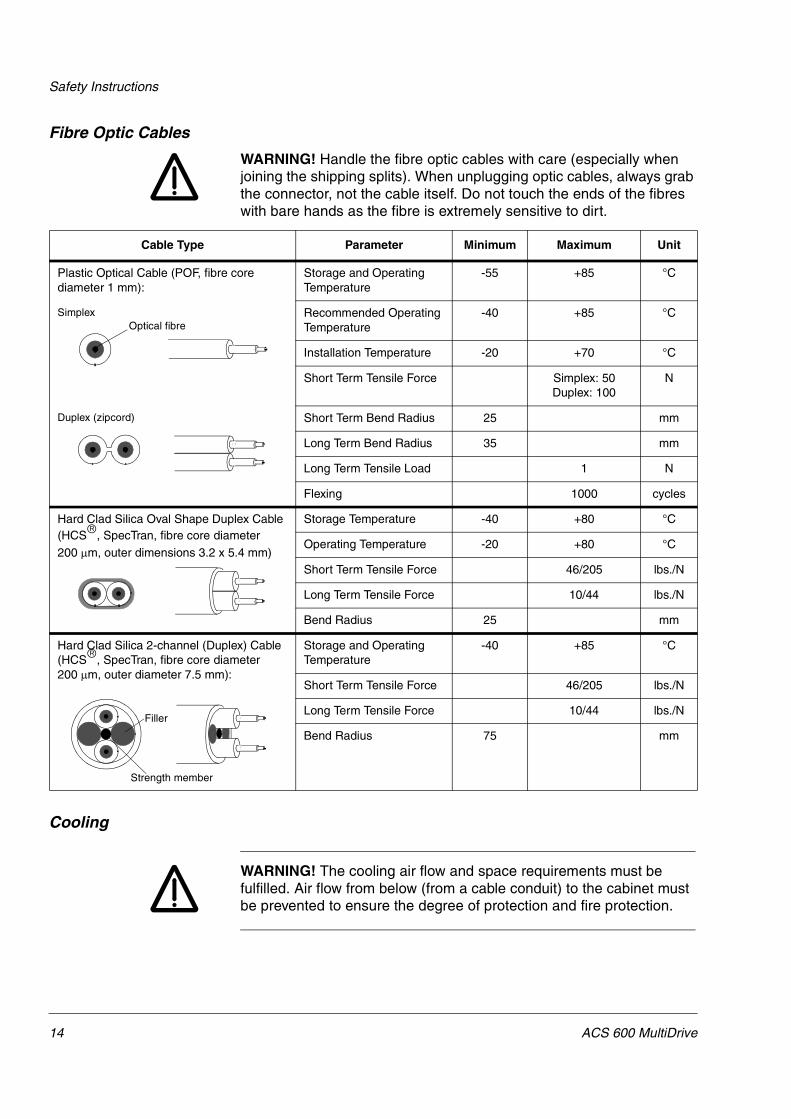
Fibre Optic Cables
WARNING! Handle the fibre optic cables with care (especially when joining the shipping splits). When unplugging optic cables, always grab the connector, not the cable itself. Do not touch the ends of the fibres with bare hands as the fibre is extremely sensitive to dirt.
Cooling
WARNING! The cooling air flow and space requirements must be fulfilled. Air flow from below (from a cable conduit) to the cabinet must be prevented to ensure the degree of protection and fire protection.
Cable Type Parameter Minimum Maximum Unit
Plastic Optical Cable (POF, fibre core diameter 1 mm):
Storage and Operating Temperature
-55 +85 °C
Simplex Recommended Operating Temperature
-40 +85 °C
Installation Temperature -20 +70 °C
Short Term Tensile Force Simplex: 50Duplex: 100
N
Duplex (zipcord) Short Term Bend Radius 25 mm
Long Term Bend Radius 35 mm
Long Term Tensile Load 1 N
Flexing 1000 cycles
Hard Clad Silica Oval Shape Duplex Cable(HCS�, SpecTran, fibre core diameter 200 �m, outer dimensions 3.2 x 5.4 mm)
Storage Temperature -40 +80 °C
Operating Temperature -20 +80 °C
Short Term Tensile Force 46/205 lbs./N
Long Term Tensile Force 10/44 lbs./N
Bend Radius 25 mm
Hard Clad Silica 2-channel (Duplex) Cable (HCS�, SpecTran, fibre core diameter 200 �m, outer diameter 7.5 mm):
Storage and Operating Temperature
-40 +85 °C
Short Term Tensile Force 46/205 lbs./N
Long Term Tensile Force 10/44 lbs./N
Bend Radius 75 mm
Optical fibre
Filler
Strength member
14 ACS 600 MultiDrive

Safety Instructions
Mechanical Installation CAUTION! Fastening any device to the cabinet frame for lifting purposes is forbidden.
CAUTION! Make sure that dust from drilling does not enter the cabinet when installing. Electrically conductive dust inside the unit may cause damage or lead to malfunction.
CAUTION! Welding of the cabinet frame is not recommended because it may damage electronic circuits located in the drive sections. However, if electric welding is the only way to mount the cabinet connect the return conductor of the welding equipment low to the cabinet frame within 0.5 metres of the welding point to reduce the risk of damage.
ACS 600 MultiDrive 15

Safety Instructions
16 ACS 600 MultiDrive

ACS 600 MultiDrive – Technical Data
Abbreviations The abbreviations used in the following supply and drive section rating tables are explained below.
Note 1: Drive section output currents are valid when output frequency is above 10 Hz.
Note 2: The ratings given correspond to voltage UN and fan supply voltage 230 V or 115 V.
Note 3: The limiting factor for PG in thyristor supply sections with autotransformer is either the autotransformer or the generator bridge current depending on the configuration of the supply section.
Supply Section Drive SectionI1N Total rms input current (continuous a.c.
current)I2N Rated rms a.c. output current (= maximum
continuous output current)Duty Cycle (10 s / 60 s) 200 % Duty Cycle (10 s / 60 s)IDCbase Maximum base current with IDCmax. IDCbase is
60 % of IDC.I2base Maximum base current with I2max. I2base is the
nominal heavy duty output current.IDCmax Short term rms overload d.c. current (allowed for
10 seconds every 60 seconds) I2max Short term rms a.c. overload current (allowed for
10 seconds every 60 seconds) i.e. maximum output current
Duty Cycle (1 min / 5 min) 150 % Duty Cycle (1 min / 5 min)IDCbase Maximum base current with IDCmax. IDCbase is
60 % of IDC.I2base Maximum base current with I2max
IDCmax Short term rms overload d.c. current (allowed for one minute every 5 minutes).
I2max Short term rms a.c. overload current (allowed for one minute every 5 minutes)
IDC Continuous d.c. currentSN Rated apparent output power of the supply
sectionSN Rated apparent output power of the drive
sectionPN Nominal output power (continuous active
power)PN Typical motor power. The power ratings in kW
apply to most IEC 34 motors.PG Regenerative braking power to mains
Ploss Power lossUN Nominal mains voltage UN Nominal mains voltage
10 s 50 s
IDCmax
IDCbase
10 s 50 s
I2max
I2base
1 min 4 min
IDCmax
IDCbase
1 min 4 min
I2max
I2base
ACS 600 MultiDrive A-1

ACS 600 MultiDrive – Technical Data
Supply Section Tables The following tables specify the ratings for the supply sections. For IGBT supply section ratings see ACA 635 IGBT Supply Sections User’s Manual (EN code 64013700).
Notes The notes concerning the supply section tables are listed below.
Ploss Ploss is the heat loss of a unit with basic options.
Noise Level Noise level applies to echoless room.
Height Cabinet height is 2072 mm for IP 54R classification.
Weight/Width Bottom and top entry weights in the following tables apply to units with basic options and aluminium DC busbars. Width (EMC) is the width of the EMC filter cabinet, Weight (EMC) is the additional weight due to the EMC filter cabinet.
An auxiliary control unit is included in every ACS 600 MultiDrive delivery. The following tables do not include the width and weight of the auxiliary control unit: 400 mm (approximately 170 kg) or 600 mm (approximately 190 kg).
A-2 ACS 600 MultiDrive

ACS 600 MultiDrive – Technical Data
Ratings 380...415 V The table below shows the nominal ratings for the 400 V range supply sections.
Type Marking Nominal Ratings Duty Cycle (10 s / 60 s)
Duty Cycle (1 min / 5 min)
Frame Air Flow
m3/h
Ploss
kW
Noise Level
dBA
SN
kVA
I1N
A
IDC
A
PN
kW
PG
kW
IDCbase
A
IDCmax
A
IDCbase
A
IDCmax
A
Diode supply sections (380...415 V Range,UN = 400 V)
ACA 631-0140-31-xx 140 202 247 131 – 148 317 148 289 B2 370 1.5 56ACA 631-0200-31-xx 200 289 354 188 – 212 455 212 414 B2 370 2.3 56ACA 631-0300-31-xx 300 433 530 282 – 318 795 318 700 B3 770 2.8 64
ACA 631-0420-31-xx 420 606 742 394 – 445 1113 445 979 B3 770 3.6 64ACA 631-0680-31-xx 680 981 1202 639 – 721 1947 721 1406 B4 1500 6.3 70ACA 631-1120-31-xx 1120 1617 1980 1053 – 1188 3208 1188 2317 B4 1500 10.2 70
ACA 631-1700-31-xx 1697 2449 3000 1595 – 1800 4860 1800 3798 B5 2800 16.5 74ACA 631-2100-31-xx 1980 2858 3500 1861 – 2100 5670 2100 4431 B5 2800 20.8 74Thyristor supply sections (380...415 V Range,UN = 400 V)
ACA 632-0015-31-xx 12 18 22 12 11 13 28 13 26 B1 150 1.1 55
ACA 632-0030-31-xx 26 37 45 24 22 27 58 27 53 B1 150 1.1 55ACA 632-0040-31-xx 38 55 67 36 32 40 86 40 78 B1 150 1.1 55ACA 632-0070-31-xx 71 102 125 66 60 75 161 75 146 B1 150 1.1 55
ACA 632-0140-31-xx 140 202 247 131 118 148 317 148 289 B2 370 1.5 56ACA 632-0200-31-xx 200 289 354 188 169 212 455 212 414 B2 370 2.3 56ACA 632-0300-31-xx 300 433 530 282 254 318 795 318 700 B3 770 2.8 64
ACA 632-0420-31-xx 420 606 742 394 355 445 1113 445 979 B3 770 3.6 64ACA 632-0680-31-xx 680 981 1202 639 575 721 1947 721 1406 B4 2500 6.3 72ACA 632-1120-31-xx 1120 1617 1980 1053 947 1188 3208 1188 2317 B4 2500 10.2 72
ACA 632-1700-31-xx 1697 2449 3000 1595 1435 1800 4860 1800 3798 B5 4500 16.5 75ACA 632-2100-31-xx 1980 2858 3500 1861 1675 2100 5670 2100 4431 B5 4500 20.8 75Asymmetrical thyristor supply sections (380...415 V Range,UN = 400 V)
ACA 632-1700/0680-31-xx 1697 2449 3000 1595 575 1800 4860 1800 3798 B5 4500 16.5 75
ACA 632-1700/1120-31-xx 1697 2449 3000 1595 947 1800 4860 1800 3798 B5 4500 16.5 75ACA 632-2100/0680-31-xx 1980 2858 3500 1861 575 2100 5670 2100 4431 B5 4500 20.8 75ACA 632-2100/1120-31-xx 1980 2858 3500 1861 947 2100 5670 2100 4431 B5 4500 20.8 75
12 pulse diode supply sections (380...415 V Range,UN = 400 V)
ACA 633-0280-31-xx 280 404 494 263 – 296 634 296 578 B2 2x370 2x1.5 56ACA 633-0400-31-xx 400 578 708 376 – 425 909 425 828 B2 2x370 2x2.3 56ACA 633-0600-31-xx 600 866 1060 564 – 636 1590 636 1399 B3 2x770 2x2.8 64
ACA 633-0840-31-xx 840 1212 1484 789 – 890 2226 890 1959 B3 2x770 2x3.6 64ACA 633-1360-31-xx 1360 1962 2404 1279 – 1442 3894 1442 2813 B4 2x1500 2x6.3 72ACA 633-2240-31-xx 2240 3234 3960 2106 – 2376 6415 2376 4633 B4 2x1500 2x10.2 72
ACA 633-3400-31-xx 3394 4898 6000 3190 – 3600 9720 3600 7596 B5 2x2800 2x16.5 756 pulse thyristor supply sections with autotransformer (380...415 V Range,UN = 400 V)
ACA 634-0200-31-xx 200 289 354 188 171 212 455 212 414 B2 370 2.3 56
ACA 634-0420-31-xx 420 606 742 394 388 445 1113 445 979 B3 770 3.6 64ACA 634-0680-31-xx 680 981 1202 639 639 721 1947 721 1406 B4 2500 6.3 72ACA 634-1120-31-xx 1120 1617 1980 1053 639 1188 3208 1188 2317 B4 2500 10.2 72
ACA 634-1700-31-xx 1697 2449 3000 1595 1065 1800 4860 1800 3798 B5 4500 16.5 75ACA 634-2100-31-xx 1980 2858 3500 1861 1065 2100 5670 2100 4431 B5 4500 20.8 7512 pulse thyristor supply sections (380...415 V Range,UN = 400 V)
ACA 636-0800-31-xx 798 1151 1410 761 685 846 2115 846 1861 B3 2x770 2x3,6 66
ACA 636-1290-31-xx 1292 1865 2284 1232 1109 1370 3700 1370 2672 B4 2x2500 2x6,3 74ACA 636-2130-31-xx 2128 3072 3763 2030 1827 2257 6094 2257 4402 B4 2x2500 2x10,2 74ACA 636-3220-31-xx 3224 4654 5701 3076 2768 3420 9234 3420 7216 B5 2x4500 2x16,5 77
12 pulse thyristor supply sections with autotransformer (380...415 V Range,UN = 400 V)
ACA 638-0800-31-xx 798 1151 1410 761 761 846 2115 846 1861 B3 2x770 2x3.6 66ACA 638-1290-31-xx 1292 1865 2284 1232 776 1370 3700 1370 2672 B4 2x2500 2x6.3 74ACA 638-2130-31-xx 2128 3072 3763 2030 1277 2257 6094 2257 4402 B4 2x2500 2x10.2 74
ACA 638-3220-31-xx 3224 4654 5701 3076 2130 3420 9234 3420 7216 B5 2x4500 2x16.5 7712/6 pulse thyristor supply sections with autotransformer (380...415 V Range,UN = 400 V)
ACA 639-0800-31-xx 798 1151 1410 761 380 846 2115 846 1861 B3 2x770 2x3.6 66ACA 639-1290-31-xx 1292 1865 2284 1232 388 1370 3700 1370 2672 B4 4000 2x6.3 74
ACA 639-2130-31-xx 2128 3072 3763 2030 639 2257 6094 2257 4402 B4 4000 2x10.2 74ACA 639-3220-31-xx 3224 4654 5701 3076 1065 3420 9234 3420 7216 B5 7300 2x16.5 77
PDM code 00001749-C
ACS 600 MultiDrive A-3

ACS 600 MultiDrive – Technical Data
Ratings 380...500 V The table below shows the nominal ratings for the 500 V range supply sections.
Type Marking Nominal Ratings Duty Cycle (10 s / 60 s)
Duty Cycle (1 min / 5 min)
Frame Air Flow
m3/h
Ploss
kW
Noise Level
dBA
SN
kVA
I1N
A
IDC
A
PN
kW
PG
kW
IDCbase
A
IDCmax
A
IDCbase
A
IDCmax
ADiode supply sections (380...500 V Range,UN = 500 V)
ACA 631-0175-51-xx 175 202 247 163 – 148 317 148 289 B2 370 1.5 56ACA 631-0250-51-xx 250 289 354 233 – 212 455 212 414 B2 370 2.3 56ACA 631-0375-51-xx 375 433 530 349 – 318 795 318 700 B3 770 2.8 64ACA 631-0525-51-xx 525 606 742 489 – 445 1113 445 979 B3 770 3.6 64ACA 631-0850-51-xx 850 981 1202 792 – 721 1947 721 1406 B4 1500 6.3 70ACA 631-1400-51-xx 1400 1617 1980 1304 – 1188 3208 1188 2317 B4 1500 10.2 70ACA 631-2120-51-xx 2120 2449 3000 1976 – 1800 4860 1800 3798 B5 2800 16.5 74ACA 631-2600-51-xx 2475 2858 3500 2305 – 2100 5670 2100 4431 B5 2800 20.8 74Thyristor supply sections (380...500 V Range,UN = 500 V)
ACA 632-0020-51-xx 16 18 22 15 13 13 28 13 26 B1 150 1.1 55ACA 632-0035-51-xx 32 37 45 30 27 27 58 27 53 B1 150 1.1 55ACA 632-0050-51-xx 47 55 67 44 40 40 86 40 78 B1 150 1.1 55ACA 632-0090-51-xx 88 102 125 82 74 75 161 75 146 B1 150 1.1 55ACA 632-0175-51-xx 175 202 247 163 147 148 317 148 289 B2 370 1.5 56ACA 632-0250-51-xx 250 289 354 233 210 212 455 212 414 B2 370 2.3 56ACA 632-0375-51-xx 375 433 530 349 314 318 795 318 700 B3 770 2.8 64ACA 632-0525-51-xx 525 606 742 489 440 445 1113 445 979 B3 770 3.6 64ACA 632-0850-51-xx 850 981 1202 792 713 721 1947 721 1406 B4 2500 6.3 72ACA 632-1400-51-xx 1400 1617 1980 1304 1174 1188 3208 1188 2317 B4 2500 10.2 72ACA 632-2120-51-xx 2120 2449 3000 1976 1778 1800 4860 1800 3798 B5 4500 16.5 75ACA 632-2600-51-xx 2475 2858 3500 2305 2074 2100 5670 2100 4431 B5 4500 20.8 75Asymmetrical thyristor supply sections (380...500 V Range,UN = 500 V)
ACA 632-2120/0850-51-xx 2120 2449 3000 1976 713 1800 4860 1800 3798 B5 4500 16.5 75ACA 632-2120/1400-51-xx 2120 2449 3000 1976 1174 1800 4860 1800 3798 B5 4500 16.5 75ACA 632-2600/0850-51-xx 2475 2858 3500 2305 713 2100 5670 2100 4431 B5 4500 20.8 75ACA 632-2600/1400-51-xx 2475 2858 3500 2305 1174 2100 5670 2100 4431 B5 4500 20.8 7512 pulse diode supply sections (380...500 V Range,UN = 500 V)
ACA 633-0350-51-xx 350 404 494 326 – 296 634 296 578 B2 2x370 2x1.5 56ACA 633-0500-51-xx 500 578 708 466 – 425 909 425 828 B2 2x370 2x2.3 56ACA 633-0750-51-xx 750 866 1060 698 – 636 1590 636 1399 B3 2x770 2x2.8 64ACA 633-1050-51-xx 1050 1212 1484 978 – 890 2226 890 1959 B3 2x770 2x3.6 64ACA 633-1700-51-xx 1700 1962 2404 1584 – 1442 3894 1442 2813 B4 2x1500 2x6.3 72ACA 633-2800-51-xx 2800 3234 3960 2608 – 2376 6415 2376 4633 B4 2x1500 2x10.2 72ACA 633-4240-51-xx 4240 4898 6000 3952 – 3600 9720 3600 7596 B5 2x2800 2x16.5 756 pulse thyristor supply sections with autotransformer (380...500 V Range,UN = 500 V)
ACA 634-0250-51-xx 250 289 354 233 190 212 455 212 414 B2 370 2.3 56ACA 634-0375-51-xx 375 433 530 349 380 318 795 318 700 B3 770 2.8 64ACA 634-0850-51-xx 850 981 1202 792 645 721 1947 721 1406 B4 2500 6.3 72ACA 634-1400-51-xx 1400 1617 1980 1304 1063 1188 3208 1188 2317 B4 2500 10.2 72ACA 634-2120-51-xx 2120 2449 3000 1976 1063 1800 4860 1800 3798 B5 4500 16.5 75ACA 634-2600-51-xx 2475 2858 3500 2305 1874 2100 5670 2100 4431 B5 4500 20.8 7512 pulse thyristor supply sections (380...500 V Range,UN = 500 V)
ACA 636-1000-51-xx 997 1151 1410 929 836 846 2115 846 1861 B3 2x770 2x3.6 66ACA 636-1615-51-xx 1614 1864 2283 1504 1353 1370 3700 1370 2672 B4 2x2500 2x6.3 74ACA 636-2660-51-xx 2661 3072 3764 2479 2231 2257 6094 2257 4402 B4 2x2500 2x10.2 74ACA 636-4030-51-xx 4030 4653 5700 3754 3378 3420 9234 3420 7216 B5 2x4500 2x16.5 77ACA 636-4700-51-xx 4703 5430 6652 4381 3943 3990 10773 3990 8419 B5 2x4500 2x20.8 7712 pulse thyristor supply sections with autotransformer (380...500 V Range,UN = 500 V)
ACA 638-1000-51-xx 997 1151 1410 929 722 846 2115 846 1861 B3 2x770 2x3.6 66ACA 638-1615-51-xx 1614 1864 2283 1504 1170 1370 3700 1370 2672 B4 2x2500 2x6.3 74ACA 638-2660-51-xx 2661 3072 3764 2479 1927 2257 6094 2257 4402 B4 2x2500 2x10.2 74ACA 638-4030-51-xx 4030 4653 5700 3754 3580 3420 9234 3420 7216 B5 2x4500 2x16.5 77ACA 638-4700-51-xx 4703 5430 6652 4381 3580 3990 10773 3990 8419 B5 2x4500 2x20.8 7712/6 pulse thyristor supply sections with autotransformer (380...500 V Range,UN = 500 V)
ACA 639-1000-51-xx 997 1151 1410 929 361 846 2115 846 1861 B3 2x770 2x3.6 66ACA 639-1615-51-xx 1614 1864 2283 1504 585 1370 3700 1370 2672 B4 4000 2x6.3 74ACA 639-2660-51-xx 2661 3072 3764 2479 963 2257 6094 2257 4402 B4 4000 2x10.2 74ACA 639-4030-51-xx 4030 4653 5700 3754 1790 3420 9234 3420 7216 B5 7300 2x16.5 77ACA 639-4700-51-xx 4703 5430 6652 4381 1790 3990 10773 3990 8419 B5 7300 2x20.8 77
PDM code 00001749-C
A-4 ACS 600 MultiDrive

ACS 600 MultiDrive – Technical Data
Ratings 525...690 V The table below shows the nominal ratings for the 690 V range supply sections.
Type Marking Nominal Ratings Duty Cycle (10 s / 60 s)
Duty Cycle (1 min / 5 min)
Frame Air Flow
m3/h
Ploss
kW
Noise Level
dBA
SN
kVA
I1N
A
IDC
A
PN
kW
PG
kW
IDCbase
A
IDCmax
A
IDCbase
A
IDCmax
A
Diode supply sections (525...690 V Range,UN = 690 V)
ACA 631-0090-61-xx 90 75 92 83 – 55 118 55 108 B2 370 0.6 56ACA 631-0175-61-xx 175 146 179 161 – 107 230 107 209 B2 370 1.5 56ACA 631-0250-61-xx 250 209 256 231 – 154 329 154 300 B2 370 2.3 56
ACA 631-0375-61-xx 375 314 384 346 – 230 576 230 507 B3 770 2.8 64ACA 631-0525-61-xx 525 439 538 484 – 323 807 323 710 B3 770 3.6 64ACA 631-0850-61-xx 850 711 871 784 – 523 1411 523 1019 B4 1500 6.3 70
ACA 631-1400-61-xx 1400 1171 1435 1292 – 861 2325 861 1679 B4 1500 10.2 70ACA 631-2600-61-xx 2600 2176 2664 2400 – 1598 4316 1598 3373 B5 2800 16.5 74ACA 631-3600-61-xx 3415 2858 3500 3152 – 2100 5670 2100 4431 B5 2800 20.8 74
Thyristor supply sections (525...690 V Range,UN = 690 V)
ACA 632-0090-61-xx 90 75 92 83 74 55 118 55 108 B2 370 0.6 56ACA 632-0175-61-xx 175 146 179 161 145 107 230 107 209 B2 370 1.5 56ACA 632-0250-61-xx 250 209 256 231 207 154 329 154 300 B2 370 2.3 56
ACA 632-0375-61-xx 375 314 384 346 312 230 576 230 507 B3 770 2.8 64ACA 632-0525-61-xx 525 439 538 484 436 323 807 323 710 B3 770 3.6 64ACA 632-0850-61-xx 850 711 871 784 706 523 1411 523 1019 B4 2500 6.3 72
ACA 632-1400-61-xx 1400 1171 1435 1292 1163 861 2325 861 1679 B4 2500 10.2 72ACA 632-2600-61-xx 2600 2176 2664 2399 2159 1598 4316 1598 3373 B5 4500 16.5 75ACA 632-3600-61-xx 3415 2858 3500 3152 2837 2100 5670 2100 4431 B5 4500 20.8 75
Asymmetrical thyristor supply sections (525...690 V Range,UN = 690 V)
ACA 632-2600/0850-61-xx 2600 2176 2664 2399 706 1598 4316 1598 3373 B5 4500 16.5 75ACA 632-2600/1400-61-xx 2600 2176 2664 2399 1163 1598 4316 1598 3373 B5 4500 16.5 75ACA 632-3600/0850-61-xx 3415 2858 3500 3152 706 2100 5670 2100 4431 B5 4500 20.8 75
ACA 632-3600/1400-61-xx 3415 2858 3500 3152 1163 2100 5670 2100 4431 B5 4500 20.8 75ACA 632-3600/2600-61-xx 3415 2858 3500 3152 2159 2100 5670 2100 4431 B5 4500 20.8 7512 pulse diode supply sections (525...690 V Range,UN = 690 V)
ACA 633-0180-61-xx 180 150 184 165 – 110 236 110 215 B2 2x370 2x0.6 56
ACA 633-0350-61-xx 350 292 358 322 – 215 460 215 419 B2 2x370 2x1.5 56ACA 633-0500-61-xx 500 418 512 461 – 307 657 307 599 B2 2x370 2x2.3 56ACA 633-0750-61-xx 750 628 768 693 – 461 1152 461 1014 B3 2x770 2x2.8 64
ACA 633-1050-61-xx 1050 878 1076 968 – 646 1614 646 1420 B3 2x770 2x3.6 64ACA 633-1700-61-xx 1700 1422 1742 1569 – 1045 2822 1045 2038 B4 2x1500 2x6.3 72ACA 633-2800-61-xx 2800 2342 2870 2583 – 1722 4649 1722 3358 B4 2x1500 2x10.2 72
ACA 633-5200-61-xx 5200 4352 5328 4798 – 3197 8631 3197 6745 B5 2x2800 2x16.5 756 pulse thyristor supply sections with autotransformer (525...690 V Range,UN = 690 V)
ACA 634-1400-61-xx 1400 1171 1435 1292 1063 861 2325 861 1679 B4 2500 10.2 72
ACA 634-2600-61-xx 2600 2176 2664 2399 1874 1598 4316 1598 3373 B5 4500 16.5 75ACA 634-3600-61-xx 3415 2858 3500 3152 1874 2100 5670 2100 4431 B5 4500 20.8 7512 pulse thyristor supply sections (525...690 V Range,UN = 690 V)
ACA 636-1000-61-xx 997 834 1022 920 828 613 1533 613 1349 B3 2x770 2x3.6 66
ACA 636-1615-61-xx 1614 1351 1655 1490 1341 993 2681 993 1936 B4 2x2500 2x6.3 74ACA 636-2660-61-xx 2659 2225 2726 2455 2209 1636 4417 1636 3190 B4 2x2500 2x10.2 74ACA 636-4950-61-xx 4941 4134 5065 4561 4105 3037 8200 3037 6408 B5 2x4500 2x16.5 77
ACA 636-6500-61-xx 6490 5430 6652 5991 5392 3990 10773 3990 8419 B5 2x4500 2x20.8 7712 pulse thyristor supply sections with autotransformer (525...690 V Range,UN = 690 V)
ACA 638-1615-61-xx 1614 1351 1655 1490 1344 993 2681 993 1936 B4 2x2500 2x6.3 74ACA 638-2660-61-xx 2659 2225 2726 2455 2214 1636 4417 1636 3190 B4 2x2500 2x10.2 74
ACA 638-4950-61-xx 4941 4134 5065 4561 3905 3037 8200 3037 6408 B5 2x4500 2x16.5 77ACA 638-6500-61-xx 6490 5430 6652 5991 3905 3990 10773 3990 8419 B5 2x4500 2x20.8 7712/6 pulse thyristor supply sections with autotransformer (525...690 V Range,UN = 690 V)
ACA 639-1615-61-xx 1614 1351 1655 1490 672 993 2681 993 1936 B4 4000 2x6.3 74
ACA 639-2660-61-xx 2659 2225 2726 2455 1107 1636 4417 1636 3190 B4 4000 2x10.2 74ACA 639-4950-61-xx 4941 4134 5065 4561 1952 3037 8200 3037 6408 B5 7300 2x16.5 77ACA 639-6500-61-xx 6490 5430 6652 5991 1952 3990 10773 3990 8419 B5 7300 2x20.8 77
PDM code 00001749-C
ACS 600 MultiDrive A-5
ACS 600 MultiDrive – Technical Data
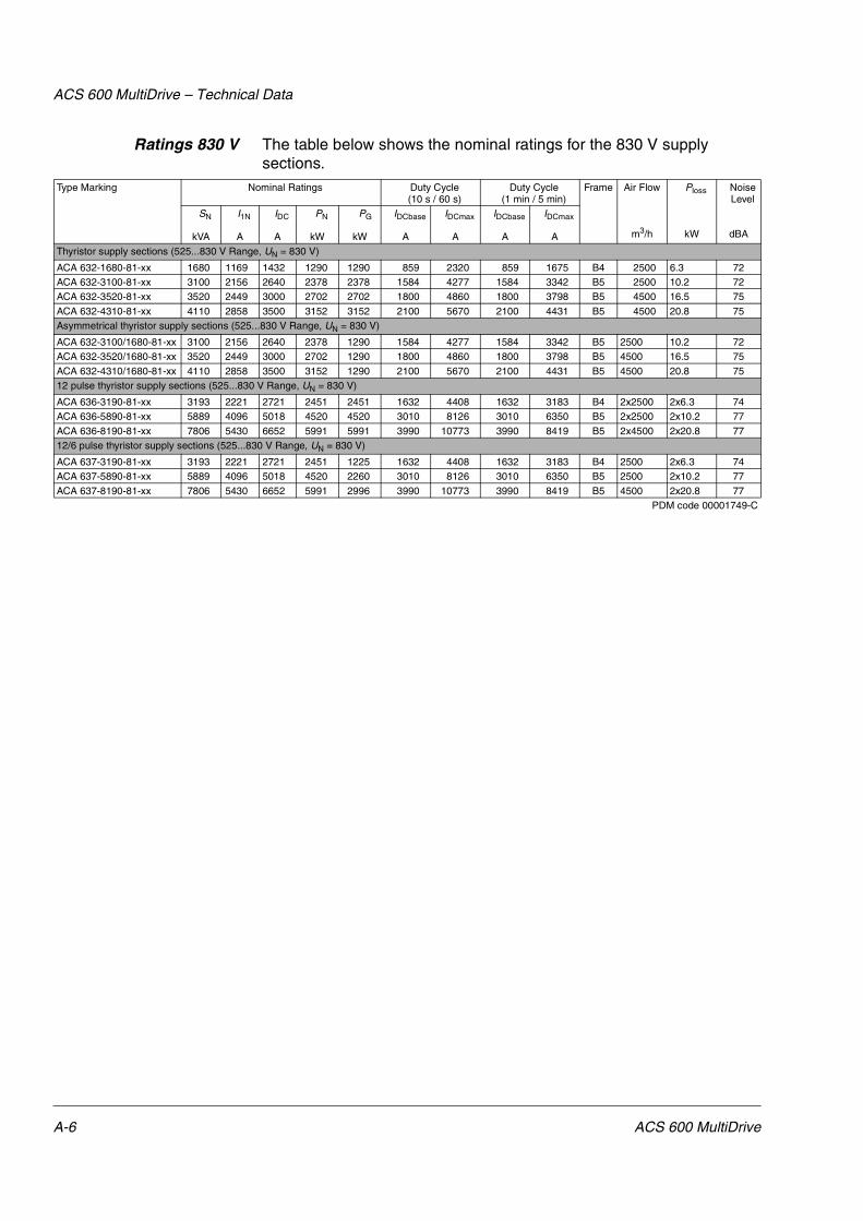
Ratings 830 V The table below shows the nominal ratings for the 830 V supply sections.
Type Marking Nominal Ratings Duty Cycle (10 s / 60 s)
Duty Cycle (1 min / 5 min)
Frame Air Flow
m3/h
Ploss
kW
Noise Level
dBA
SN
kVA
I1N
A
IDC
A
PN
kW
PG
kW
IDCbase
A
IDCmax
A
IDCbase
A
IDCmax
A
Thyristor supply sections (525...830 V Range, UN = 830 V)
ACA 632-1680-81-xx 1680 1169 1432 1290 1290 859 2320 859 1675 B4 2500 6.3 72ACA 632-3100-81-xx 3100 2156 2640 2378 2378 1584 4277 1584 3342 B5 2500 10.2 72ACA 632-3520-81-xx 3520 2449 3000 2702 2702 1800 4860 1800 3798 B5 4500 16.5 75
ACA 632-4310-81-xx 4110 2858 3500 3152 3152 2100 5670 2100 4431 B5 4500 20.8 75Asymmetrical thyristor supply sections (525...830 V Range, UN = 830 V)
ACA 632-3100/1680-81-xx 3100 2156 2640 2378 1290 1584 4277 1584 3342 B5 2500 10.2 72ACA 632-3520/1680-81-xx 3520 2449 3000 2702 1290 1800 4860 1800 3798 B5 4500 16.5 75
ACA 632-4310/1680-81-xx 4110 2858 3500 3152 1290 2100 5670 2100 4431 B5 4500 20.8 7512 pulse thyristor supply sections (525...830 V Range, UN = 830 V)
ACA 636-3190-81-xx 3193 2221 2721 2451 2451 1632 4408 1632 3183 B4 2x2500 2x6.3 74ACA 636-5890-81-xx 5889 4096 5018 4520 4520 3010 8126 3010 6350 B5 2x2500 2x10.2 77
ACA 636-8190-81-xx 7806 5430 6652 5991 5991 3990 10773 3990 8419 B5 2x4500 2x20.8 7712/6 pulse thyristor supply sections (525...830 V Range, UN = 830 V)
ACA 637-3190-81-xx 3193 2221 2721 2451 1225 1632 4408 1632 3183 B4 2500 2x6.3 74ACA 637-5890-81-xx 5889 4096 5018 4520 2260 3010 8126 3010 6350 B5 2500 2x10.2 77
ACA 637-8190-81-xx 7806 5430 6652 5991 2996 3990 10773 3990 8419 B5 4500 2x20.8 77PDM code 00001749-C
A-6 ACS 600 MultiDrive

ACS 600 MultiDrive – Technical Data
Autotransformer Data The table below shows the nominal ratings for thyristor supply autotransformers. Type Marking Autotransformer Forward
BridgeType
Reverse BridgeType
Type SN
kVA
Srms
kVA
I1
A
U1
V400 V Range6 pulse thyristor supply sections with autotransformer (380...415 V Range,UN = 400 V)
ACA 634-0200-31-xx NDAT-08 299 214 416 415 ACN654 0250 5 ACN664 0250 5
ACA 634-0420-31-xx NDAT-09 677 485 942 415 ACN654 0525 5 ACN664 0525 5ACA 634-0680-31-xx NDAT-10 1115 798 1552 415 ACN654 0850 5 ACN664 0850 5ACA 634-1120-31-xx NDAT-10 1115 798 1552 415 ACN654 1400 5 ACN664 1400 5
ACA 634-1700-31-xx NDAT-11 1859 1331 2587 415 ACN654 2120 5 ACN664 2120 5ACA 634-2100-31-xx NDAT-11 1859 1331 2587 415 ACN654 2600 5 ACN664 2600 512 pulse thyristor supply sections with autotransformer (380...415 V Range,UN = 400 V)
ACA 638-0800-31-xx NDAT-09 677 485 942 415 ACN654 0525 5 ACN664 0525 5
ACA 638-1290-31-xx NDAT-09 677 485 942 415 ACN654 0855 5 ACN664 0855 5ACA 638-2130-31-xx NDAT-10 1115 798 1552 415 ACN654 1405 5 ACN664 1405 5ACA 638-3220-31-xx NDAT-11 1859 1331 2587 415 ACN654 2120 5 ACN664 2120 5
12/6 pulse thyristor supply sections with autotransformer (380...415 V Range,UN = 400 V)
ACA 639-0800-31-xx NDAT-09 677 485 942 415 ACN654 0525 5 ACN664 0525 5ACA 639-1290-31-xx NDAT-09 677 485 942 415 ACN654 0855 5 ACN664 0855 5ACA 639-2130-31-xx NDAT-10 1115 798 1552 415 ACN654 1405 5 ACN664 1405 5
ACA 639-3220-31-xx NDAT-11 1859 1331 2587 415 ACN654 2120 5 ACN664 2120 5500 V Range6 pulse thyristor supply sections with autotransformer (380...500 V Range,UN = 500 V)
ACA 634-0250-51-xx NDAT-02 331 237 277 690 ACN654 0250 5 ACN664 0375 6
ACA 634-0375-51-xx NDAT-03 696 498 582 690 ACN654 0375 5 ACN664 0525 6ACA 634-0850-51-xx NDAT-04 1126 806 942 690 ACN654 0850 5 ACN664 1400 6ACA 634-1400-51-xx NDAT-05 1855 1328 1552 690 ACN654 1400 5 ACN664 2600 6
ACA 634-2120-51-xx NDAT-05 1855 1328 1552 690 ACN654 2120 5 ACN664 2600 5ACA 634-2600-51-xx NDAT-06 3272 2343 2282 690 ACN654 2600 5 ACN664 3600 512 pulse thyristor supply sections with autotransformer (380...500 V Range,UN = 500 V)
ACA 638-1000-51-xx NDAT-03 696 498 582 690 ACN654 0525 5 ACN664 0525 6
ACA 638-1615-51-xx NDAT-04 1126 806 942 690 ACN654 0855 5 ACN664 0855 6ACA 638-2660-51-xx NDAT-05 1855 1328 1552 690 ACN654 1405 5 ACN664 1405 6ACA 638-4030-51-xx NDAT-06 3272 2343 2738 690 ACN654 2120 5 ACN664 2600 6
ACA 638-4700-51-xx NDAT-06 3272 2343 2738 690 ACN654 2600 5 ACN664 2600 612/6 pulse thyristor supply sections with autotransformer (380...500 V Range,UN = 500 V)
ACA 639-1000-51-xx NDAT-03 696 498 582 690 ACN654 0525 5 ACN664 0525 6
ACA 639-1615-51-xx NDAT-04 1126 806 942 690 ACN654 0855 5 ACN664 0855 6ACA 639-2660-51-xx NDAT-05 1855 1328 1552 690 ACN654 1405 5 ACN664 1405 6ACA 639-4030-51-xx NDAT-06 3272 2343 2738 690 ACN654 2120 5 ACN664 2600 6
ACA 639-4700-51-xx NDAT-06 3272 2343 2738 690 ACN654 2600 5 ACN664 2600 6690 V Range6 pulse thyristor supply sections with autotransformer (525...690 V Range,UN = 690 V)
ACA 634-1400-61-xx NDAT-05 1855 1328 1552 690 ACN654 1400 6 ACN664 1680 8
ACA 634-2600-61-xx NDAT-06 3272 2343 2282 690 ACN654 2600 6 ACN664 3100 8ACA 634-3600-61-xx NDAT-06 3272 2343 2282 690 ACN654 3600 6 ACN664 4210 812 pulse thyristor supply sections with autotransformer (525...690 V Range,UN = 690 V)
ACA 638-1615-61-xx NDAT-04 1126 806 942 690 ACN654 0855 6 ACN664 1680 8
ACA 638-2660-61-xx NDAT-05 1855 1328 1552 690 ACN654 1405 6 ACN664 1680 8ACA 638-4950-61-xx NDAT-06 3272 2343 2738 690 ACN654 2600 6 ACN664 3100 8ACA 638-6500-61-xx NDAT-06 3272 2343 2738 690 ACN654 3600 6 ACN664 3100 8
12/6 pulse thyristor supply sections with autotransformer (525...690 V Range,UN = 690 V)
ACA 639-1615-61-xx NDAT-04 1126 806 942 690 ACN654 0855 6 ACN664 1680 8ACA 639-2660-61-xx NDAT-05 1855 1328 1552 690 ACN654 1405 6 ACN664 1680 8ACA 639-4950-61-xx NDAT-06 3272 2343 2738 690 ACN654 2600 6 ACN664 3100 8
ACA 639-6500-61-xx NDAT-06 3272 2343 2738 690 ACN654 3600 6 ACN664 3100 8PDM code 00001749-C
ACS 600 MultiDrive A-7

ACS 600 MultiDrive – Technical Data
Dimensions andWeights 400 V
The table below shows the dimensions and weights of the 400 V range supply sections. See notes on page A-2.
Type Marking Height
mm
Bottom Entry:Width
mm
Top Entry:Width
mm
Depth
mm
Bottom Entry:Weight
kg
Top Entry:Weight
kg
Width(EMC)
mm
Weight(EMC)
kg
Diode supply sections (380...415 V Range)ACA 631-0140-31-xx 2065 400 800 (400+400) 600 300 420 400 100ACA 631-0200-31-xx 2065 400 800 (400+400) 600 300 420 400 100
ACA 631-0300-31-xx 2065 600 1200 (600+600) 600 380 510 400 120ACA 631-0420-31-xx 2065 600 1200 (600+600) 600 380 510 600 120ACA 631-0680-31-xx 2065 1600 (600+400+600) 1600 (600+400+600) 600 1300 1300 600 150
ACA 631-1120-31-xx 2130 1600 (600+400+600) 1600 (600+400+600) 600 1300 1300 – –ACA 631-1700-31-xx 2130 1600 (600+400+600) 1600 (600+400+600) 600 1600 1600 – –ACA 631-2100-31-xx 2130 1600 (600+400+600) 1600 (600+400+600) 600 1600 1600 – –
Thyristor supply sections (380...415 V Range)ACA 632-0015-31-xx 2065 400 400 600 250 250 – –ACA 632-0030-31-xx 2065 400 400 600 250 250 – –
ACA 632-0040-31-xx 2065 400 400 600 250 250 – –ACA 632-0070-31-xx 2065 400 400 600 250 250 – –ACA 632-0140-31-xx 2065 400 800 (400+400) 600 300 420 – –
ACA 632-0200-31-xx 2065 400 800 (400+400) 600 300 420 – –ACA 632-0300-31-xx 2065 600 1200 (600+600) 600 380 510 – –ACA 632-0420-31-xx 2065 600 1200 (600+600) 600 380 510 – –
ACA 632-0680-31-xx 2130 2200 (600+400+600+600) 2200 (600+400+600+600) 600 1500 1500 – –ACA 632-1120-31-xx 2130 2200 (600+400+600+600) 2200 (600+400+600+600) 600 1500 1500 – –ACA 632-1700-31-xx 2130 2200 (600+400+600+600) 2200 (600+400+600+600) 600 1900 1900 – –
ACA 632-2100-31-xx 2130 2200 (600+400+600+600) 2200 (600+400+600+600) 600 1900 1900 – –Asymmetrical thyristor supply sections (380...415 V Range,UN = 400 V)
ACA 632-1700/0680-31-xx 2130 2200 (600+400+600+600) 2200 (600+400+600+600) 600 1900 1900 – –ACA 632-1700/1120-31-xx 2130 2200 (600+400+600+600) 2200 (600+400+600+600) 600 1900 1900 – –
ACA 632-2100/0680-31-xx 2130 2200 (600+400+600+600) 2200 (600+400+600+600) 600 1900 1900 – –ACA 632-2100/1120-31-xx 2130 2200 (600+400+600+600) 2200 (600+400+600+600) 600 1900 1900 – –12 pulse diode supply sectios (380...415 V Range)
ACA 633-0280-31-xx 2065 800 (2x400) 1600 (2x(400+400)) 600 480 720 – –ACA 633-0400-31-xx 2065 800 (2x400) 1600 (2x(400+400)) 600 480 720 – –ACA 633-0600-31-xx 2065 1200 (2x600) 2400 (2x(600+600)) 600 640 900 – –
ACA 633-0840-31-xx 2065 1200 (2x600) 2400 (2x(600+600)) 600 640 900 – –ACA 633-1360-31-xx 2130 3200 (2x(600+400+600) 3200 (2x(600+400+600) 600 2400 2400 – –ACA 633-2240-31-xx 2130 3200 (2x(600+400+600) 3200 (2x(600+400+600) 600 2400 2400 – –
ACA 633-3400-31-xx 2130 3200 (2x(600+400+600) 3200 (2x(600+400+600) 600 3000 3000 – –6 pulse thyristor supply sections with autotransformer (380...415 V Range,UN = 400 V)
ACA 634-0200-31-xx 2065 1400 (400+600+400) 1800 (400+400+600+400) 600 950 1050 – –ACA 634-0420-31-xx 2065 2000 (600+800+600) 2600 (600+600+800+600) 600 1250 1400 – –
ACA 634-0680-31-xx 2130 3000 (600+400+600+800+600) 3000 (600+400+600+800+600) 600 2000 2000 – –ACA 634-1120-31-xx 2130 3000 (600+400+600+800+600) 3000 (600+400+600+800+600) 600 2000 2000 – –ACA 634-1700-31-xx 2130 3200 (600+400+600+1000+600) 3200 (600+400+600+1000+600) 600 2700 2700 – –
ACA 634-2100-31-xx 2130 3200 (600+400+600+1000+600) 3200 (600+400+600+1000+600) 600 2700 2700 – –12 pulse thyristor supply sections (380...415 V Range,UN = 400 V)
ACA 636-0800-31-xx 2065 2x600 2x1200 (2x(600+600)) 600 760 1020 – –ACA 636-1290-31-xx 2130 4600 4600 600 3100 3100 – –
ACA 636-2130-31-xx 2130 4600 4600 600 3100 3100 – –ACA 636-3220-31-xx 2130 4600 4600 600 3100 3100 – –12 pulse thyristor supply sections with autotransformer (380...415 V Range,UN = 400 V)
ACA 638-0800-31-xx 2065 4200 5400 600 2560 2880 – –ACA 638-1290-31-xx 2130 6200 6200 600 4100 4100 – –ACA 638-2130-31-xx 2130 6200 6200 600 4100 4100 – –
ACA 638-3220-31-xx 2130 6600 6600 600 5500 5500 – –12/6 pulse thyristor supply sections with autotransformer (380...415 V Range,UN = 400 V)
ACA 639-0800-31-xx 2065 2600 (600+800+600+600) 3800 600 1640 1900 – –ACA 639-1290-31-xx 2130 4800 4800 600 3400 3400 – –
ACA 639-2130-31-xx 2130 4800 4800 600 3400 3400 – –ACA 639-3220-31-xx 2130 5000 5000 600 4100 4100 – –
PDM code 00001749-C
A-8 ACS 600 MultiDrive

ACS 600 MultiDrive – Technical Data
Dimensions andWeights 500 V
The table below shows the dimensions and weights of the 500 V range supply sections. See notes on page A-2.
Type Marking Height
mm
Bottom Entry:Width
mm
Top Entry:Width
mm
Depth
mm
Bottom Entry:Weight
kg
Top Entry:Weight
kg
Width(EMC)
mm
Weight(EMC)
kg
Diode supply sections (440...500 V Range) ACA 631-0175-51-xx 2065 400 800 (400+400) 600 300 420 400 100ACA 631-0250-51-xx 2065 400 800 (400+400) 600 300 420 400 100ACA 631-0375-51-xx 2065 600 1200 (600+600) 600 380 510 600 120ACA 631-0525-51-xx 2065 600 1200 (600+600) 600 380 510 600 120ACA 631-0850-51-xx 2130 1600 (600+400+600) 1600 (600+400+600) 600 1300 1300 600 150ACA 631-1400-51-xx 2130 1600 (600+400+600) 1600 (600+400+600) 600 1300 1300 – –ACA 631-2120-51-xx 2130 1600 (600+400+600) 1600 (600+400+600) 600 1600 1600 – –ACA 631-2600-51-xx 2130 1600 (600+400+600) 1600 (600+400+600) 600 1600 1600 – –Thyristor supply sections (440...500 V Range) ACA 632-0020-51-xx 2065 400 400 600 250 250 – –ACA 632-0035-51-xx 2065 400 400 600 250 250 – –ACA 632-0050-51-xx 2065 400 400 600 250 250 – –ACA 632-0090-51-xx 2065 400 400 600 250 250 – –ACA 632-0175-51-xx 2065 400 800 (400+400) 600 300 420 – –ACA 632-0250-51-xx 2065 400 800 (400+400) 600 300 420 – –ACA 632-0375-51-xx 2065 600 1200 (600+600) 600 380 510 – –ACA 632-0525-51-xx 2065 600 1200 (600+600) 600 380 510 – –ACA 632-0850-51-xx 2130 2200 (600+400+600+600) 2200 (600+400+600+600) 600 1500 1500 – –ACA 632-1400-51-xx 2130 2200 (600+400+600+600) 2200 (600+400+600+600) 600 1500 1500 – –ACA 632-2120-51-xx 2130 2200 (600+400+600+600) 2200 (600+400+600+600) 600 1900 1900 – –ACA 632-2600-51-xx 2130 2200 (600+400+600+600) 2200 (600+400+600+600) 600 1900 1900 – –Asymmetrical thyristor supply sections (380...500 V Range,UN = 500 V)
ACA 632-2120/0850-51-xx 2130 2200 (600+400+600+600) 2200 (600+400+600+600) 600 1900 1900 – –ACA 632-2120/1400-51-xx 2130 2200 (600+400+600+600) 2200 (600+400+600+600) 600 1900 1900ACA 632-2600/0850-51-xx 2130 2200 (600+400+600+600) 2200 (600+400+600+600) 600 1900 1900 – –ACA 632-2600/1400-51-xx 2130 2200 (600+400+600+600) 2200 (600+400+600+600) 600 1900 190012 pulse diode supply sections (440...500 V Range) ACA 633-0350-51-xx 2065 800 (2x400) 1600 (2x(400+400)) 600 480 720 – –ACA 633-0500-51-xx 2065 800 (2x400) 1600 (2x(400+400)) 600 480 720 – –ACA 633-0750-51-xx 2065 1200 (2x600) 2400 (2x(600+600)) 600 640 900 – –ACA 633-1050-51-xx 2065 1200 (2x600) 2400 (2x(600+600)) 600 640 900 – –ACA 633-1700-51-xx 2130 3200 (2x(600+400+600) 3200 (2x(600+400+600) 600 2400 2400 – –ACA 633-2800-51-xx 2130 3200 (2x(600+400+600) 3200 (2x(600+400+600) 600 2400 2400 – –ACA 633-4240-51-xx 2130 3200 (2x(600+400+600) 3200 (2x(600+400+600) 600 3000 3000 – –6 pulse thyristor supply sections with autotransformer (380...500 V Range,UN = 500 V)
ACA 634-0250-51-xx 2065 1400 (400+600+400) 1800 (400+400+600+400) 600 950 1050 – –ACA 634-0375-51-xx 2065 2000 (600+800+600) 2600 (600+600+800+600) 600 1250 1400ACA 634-0850-51-xx 2130 3000 (600+400+600+800+600) 3000 (600+400+600+800+600) 600 2000 2000 – –ACA 634-1400-51-xx 2130 3200 (600+400+600+1000+600) 3200 (600+400+600+1000+600) 600 2700 2700ACA 634-2120-51-xx 2130 3200 (600+400+600+1000+600) 3200 (600+400+600+1000+600) 600 2700 2700 – –ACA 634-2600-51-xx 2130 3700 (600+400+600+1500+600) 3700 (600+400+600+1500+600) 600 3700 370012 pulse thyristor supply sections (380...500 V Range,UN = 500 V)
ACA 636-1000-51-xx 2065 2x600 2x1200 (600+600) 600 760 1020 – –ACA 636-1615-51-xx 2130 4600 4600 600 3100 3100ACA 636-2660-51-xx 2130 4600 4600 600 3100 3100 – –ACA 636-4030-51-xx 2130 4600 4600 600 3100 3100ACA 636-4700-51-xx 2130 4600 4600 600 3100 3100 – –12 pulse thyristor supply sections with autotransformer (380...500 V Range,UN = 500 V)
ACA 638-1000-51-xx 2065 4200 5400 600 2460 2880 – –ACA 638-1615-51-xx 2130 6200 6200 600 4100 4100ACA 638-2660-51-xx 2130 6600 6600 600 5500 5500 – –ACA 638-4030-51-xx 2130 8000 8000 600 7500 7500ACA 638-4700-51-xx 2130 8000 8000 600 7500 7500 – –12/6 pulse thyristor supply sections with autotransformer (380...500 V Range,UN = 500 V)
ACA 639-1000-51-xx 2065 2600 (600+800+600+600) 3800 600 1640 1900 – –ACA 639-1615-51-xx 2130 4800 4800 600 3400 3400ACA 639-2660-51-xx 2130 5000 5000 600 4100 4100 – –ACA 639-4030-51-xx 2130 5700 5700 600 5100 5100ACA 639-4700-51-xx 2130 5700 5700 600 5100 5100 – –
PDM code 00001749-C
ACS 600 MultiDrive A-9

ACS 600 MultiDrive – Technical Data
Dimensions andWeights 690 V
The table below shows the dimensions and weights of the 690 V range supply sections. See notes on page A-2.
Type Marking Height
mm
Bottom Entry:Width
mm
Top Entry:Width
mm
Depth
mm
Bottom Entry:Weight
kg
Top Entry:Weight
kg
Width(EMC)
mm
Weight(EMC)
kg
Diode supply sections (525...690 V Range)ACA 631-0090-61-xx 2065 400 800 600 300 420 400 100ACA 631-0175-61-xx 2065 400 800 (400+400) 600 300 420 400 100
ACA 631-0250-61-xx 2065 400 800 (400+400) 600 300 420 400 100ACA 631-0375-61-xx 2065 600 1200 (600+600) 600 380 510 600 120ACA 631-0525-61-xx 2065 600 1200 (600+600) 600 380 510 600 120
ACA 631-0850-61-xx 2130 1600 (600+400+600) 1600 (600+400+600) 600 1300 1300 600 150ACA 631-1400-61-xx 2130 1600 (600+400+600) 1600 (600+400+600) 600 1300 1300 – –ACA 631-2600-61-xx 2130 1600 (600+400+600) 1600 (600+400+600) 600 1600 1600 – –
ACA 631-3600-61-xx 2130 1600 (600+400+600) 1600 (600+400+600) 600 1600 1600 – –Thyristor supply sections (525...690 V Range)ACA 632-0090-61-xx 2065 400 800 (400+400) 600 300 420 – –
ACA 632-0175-61-xx 2065 400 800 (400+400) 600 300 420 – –ACA 632-0250-61-xx 2065 400 800 (400+400) 600 300 420 – –ACA 632-0375-61-xx 2065 600 1200 (600+600) 600 380 510 – –
ACA 632-0525-61-xx 2065 600 1200 (600+600) 600 380 510 – –ACA 632-0850-61-xx 2130 2200 (600+400+600+600) 2200 (600+400+600+600) 600 1500 1500 – –ACA 632-1400-61-xx 2130 2200 (600+400+600+600) 2200 (600+400+600+600) 600 1500 1500 – –
ACA 632-2600-61-xx 2130 2200 (600+400+600+600) 2200 (600+400+600+600) 600 1900 1900 – –ACA 632-3600-61-xx 2130 2200 (600+400+600+600) 2200 (600+400+600+600) 600 1900 1900 – –Asymmetrical thyristor supply sections (525...690 V Range,UN = 690 V)
ACA 632-2600/0850-61-xx 2130 2200 (600+400+600+600) 2200 (600+400+600+600) 600 1900 1900 – –
ACA 632-2600/1400-61-xx 2130 2200 (600+400+600+600) 2200 (600+400+600+600) 600 1900 1900ACA 632-3600/0850-61-xx 2130 2200 (600+400+600+600) 2200 (600+400+600+600) 600 1900 1900 – –ACA 632-3600/1400-61-xx 2130 2200 (600+400+600+600) 2200 (600+400+600+600) 600 1900 1900
ACA 632-3600/2600-61-xx 2130 2200 (600+400+600+600) 2200 (600+400+600+600) 600 1900 1900 – –12 pulse diode supply sections (525...690 V Range) ACA 633-0180-61-xx 2065 800 (2x400) 1600 (2x(400+400)) 600 480 720 – –
ACA 633-0350-61-xx 2065 800 (2x400) 1600 (2x(400+400)) 600 480 720 – –ACA 633-0500-61-xx 2065 800 (2x400) 1600 (2x(400+400)) 600 480 720 – –ACA 633-0750-61-xx 2065 1200 (2x600) 2400 (2x(600+600)) 600 640 900 – –
ACA 633-1050-61-xx 2065 1200 (2x600) 2400 (2x(600+600)) 600 640 900 – –ACA 633-1700-61-xx 2130 3200 (2x(600+400+600) 3200 (2x(600+400+600) 600 2400 2400 – –ACA 633-2800-61-xx 2130 3200 (2x(600+400+600) 3200 (2x(600+400+600) 600 2400 2400 – –
ACA 633-5200-61-xx 2130 3200 (2x(600+400+600) 3200 (2x(600+400+600) 600 3000 3000 – –6 pulse thyristor supply sections with autotransformer (525...690 V Range,UN = 690 V)
ACA 634-1400-61-xx 2130 3200 (600+400+600+1000+600) 3200 (600+400+600+1000+600) 600 2700 2700 – –ACA 634-2600-61-xx 2130 3700 (600+400+600+1500+600) 3700 (600+400+600+1500+600) 600 3700 3700
ACA 634-3600-61-xx 2130 3700 (600+400+600+1500+600) 3700 (600+400+600+1500+600) 600 3700 3700 – –12 pulse thyristor supply sections (525...690 V Range,UN = 690 V)
ACA 636-1000-61-xx 2065 2x600 2x1200 (600+600) 600 760 1020 – –ACA 636-1615-61-xx 2130 4600 4600 600 3100 3100
ACA 636-2660-61-xx 2130 4600 4600 600 3100 3100 – –ACA 636-4950-61-xx 2130 4600 4600 600 3100 3100ACA 636-6500-61-xx 2130 4600 4600 600 3100 3100 – –
12 pulse thyristor supply sections with autotransformer (525...690 V Range,UN = 690 V)
ACA 638-1615-61-xx 2130 6200 6200 600 4100 4100 – –ACA 638-2660-61-xx 2130 6600 6600 600 5500 5500
ACA 638-4950-61-xx 2130 8000 8000 600 7500 7500 – –ACA 638-6500-61-xx 2130 8000 8000 600 7500 750012/6 pulse thyristor supply sections with autotransformer (525...690 V Range,UN = 690 V)
ACA 639-1615-61-xx 2130 4800 4800 600 3400 3400 – –
ACA 639-2660-61-xx 2130 5000 5000 600 4100 4100ACA 639-4950-61-xx 2130 5700 5700 600 5100 5100 – –ACA 639-6500-61-xx 2130 5700 5700 600 5100 5100
PDM code 00001749-C
A-10 ACS 600 MultiDrive

ACS 600 MultiDrive – Technical Data
Dimensions andWeights 830 V
The table below shows the dimensions and weights of the 830 V supply sections. See notes on page A-2.
Type Marking Height
mm
Bottom Entry:Width
mm
Top Entry:Width
mm
Depth
mm
Bottom Entry:Weight
kg
Top Entry:Weight
kg
Width(EMC)
mm
Weight(EMC)
kg
Thyristor supply sections (830 V) ACA 632-1680-81-xx 2130 2200 (600+400+600+600) 2200 (600+400+600+600) 600 1500 1500 – –ACA 632-3100-81-xx 2130 2200 (600+400+600+600) 2200 (600+400+600+600) 600 1500 1500 – –
ACA 632-3520-81-xx 2130 2200 (600+400+600+600) 2200 (600+400+600+600) 600 1900 1900 – –ACA 632-4210-81-xx 2130 2200 (600+400+600+600) 2200 (600+400+600+600) 600 1900 1900 – –Asymmetrical thyristor supply sections (525...830 V Range, UN = 830 V)
ACA 632-3100/1680-81-xx 2130 2200 (600+400+600+600) 2200 (600+400+600+600) 600 1500 1500 – –
ACA 632-3520/1680-81-xx 2130 2200 (600+400+600+600) 2200 (600+400+600+600) 600 1900 1900ACA 632-4310/1680-81-xx 2130 2200 (600+400+600+600) 2200 (600+400+600+600) 600 1900 1900 – –12 pulse thyristor supply sections (525...830 V Range, UN = 830 V)
ACA 636-3190-81-xx 2130 4600 4600 600 3100 3100 – –
ACA 636-5890-81-xx 2130 4600 4600 600 3100 3100ACA 636-8190-81-xx 2130 4600 4600 600 3100 3100 – –12/6 pulse thyristor supply sections (525...830 V Range, UN = 830 V)
ACA 637-3190-81-xx 2130 4000 4000 600 2900 2900 – –
ACA 637-5890-81-xx 2130 4000 4000 600 2900 2900ACA 637-8190-81-xx 2130 4000 4000 600 2900 2900 – –
PDM code 00001749-C
ACS 600 MultiDrive A-11

ACS 600 MultiDrive – Technical Data
Drive Section Tables The following tables specify the ratings for the drive sections.
Notes The notes concerning the following drive section tables are listed below.
Ploss Ploss is the heat loss of a unit with basic options.
Noise Level Noise level applies to echoless room.
Height The height of the cabinet for IP 21/22/42 classification is 2065 mm up to frame type R7i. The height of frame type R8i and above is 2130 mm. Cabinet height is 2072 mm for IP 54R classification.
Depth The depth of the cabinet is 600 mm.
Width and WeightNote Description Weight
kg1 200 mm is added with the top exit 40
2 400 mm is added with the top exit 1103 600 mm is added with the top exit 1604 800 mm is added with the top exit and/or common motor
connection terminals230
5 600 mm is added with the top exit and/or common motor connection terminals
190
6 The width is 400 mm with no options and 600 mm when optional devices are included. 600 mm is added when more than one inverter unit is used in the drive section.
7 200 mm wide joining cabinet is added (max. transportation length is 4000 mm)
40
PDM code 00004863-D
A-12 ACS 600 MultiDrive

ACS 600 MultiDrive – Technical Data
Ratings 400 V The table below shows the nominal ratings for the 400 V range drive sections.
Type Marking Nominal Ratings Duty Cycle (10 s / 60 s)
Duty Cycle (1 min / 5 min) Frame
typePloss
kW
Air flow
m3/h
Noise level
dBA
Width
mm
Weight
kg
Notes
SN
kVA
PN
kW
I2N
A
I2base
A
I2max
A
I2base
A
I2max
A
Drive sections (380...500 V Range, UN = 400 V)
ACA 610-05/00/00-3 5 3 7.6 6.2 12 6.2 9.3 R2i 0.08 40 48 400 170 1ACA 610-05/05/00-3 2xR2i 0.16 80 50 400 or 600 210 1, 6
ACA 610-05/05/05-3 3xR2i 0.24 120 51 400 or 600 220 1, 6ACA 610-06/00/00-3 6 4 11 7.6 15 7.6 11 R2i 0.09 40 48 400 170 1ACA 610-06/06/00-3 2xR2i 0.18 80 50 400 or 600 210 1, 6
ACA 610-06/06/06-3 3xR2i 0.27 120 51 400 or 600 220 1, 6ACA 610-09/00/00-3 9 5.5 15 11 22 11 17 R2i 0.14 40 48 400 170 1ACA 610-09/09/00-3 2xR2i 0.28 80 50 400 or 600 210 1, 6
ACA 610-09/09/09-3 3xR2i 0.42 120 51 400 or 600 220 1, 6ACA 610-11/00/00-3 11 7.5 18 15 30 15 23 R3i 0.17 60 48 400 180 1ACA 610-11/11/00-3 2xR3i 0.34 120 50 400 or 600 220 1, 6
ACA 610-11/11/11-3 3xR3i 0.51 180 51 400 or 600 230 1, 6ACA 610-16/00/00-3 16 11 24 18 36 18 27 R3i 0.24 60 48 400 180 1ACA 610-16/16/00-3 2xR3i 0.48 120 50 400 or 600 220 1, 6
ACA 610-16/16/16-3 3xR3i 0.72 180 51 400 or 600 230 1, 6ACA 610-020/000-3 20 15 32 24 48 24 36 R4i 0.30 70 54 400 190 1ACA 610-020/020-3 2xR4i 0.60 140 54 400 or 600 240 1, 6
ACA 610-025/000-3 25 18.5 41 32 64 32 48 R4i 0.38 100 54 400 190 1ACA 610-025/025-3 2xR4i 0.76 200 54 400 or 600 240 1, 6ACA 610-030/000-3 30 22 47 41 82 41 62 R5i 0.45 260 54 400 190 1
ACA 610-030/030-3 2xR5i 0.90 520 54 400 or 600 240 1, 6ACA 610-040/000-3 40 30 62 47 94 47 71 R5i 0.60 260 54 400 190 1ACA 610-040/040-3 2xR5i 1.20 520 54 400 or 600 240 1, 6
ACA 610-050/000-3 50 37 76 62 124 62 93 R5i 0.75 260 54 400 190 1ACA 610-050/050-3 2xR5i 1.50 520 54 400 or 600 240 1, 6ACA 610-060/000-3 60 45 89 76 152 76 114 R6i 0.90 480 64 400 200 1
ACA 610-060/060-3 2xR6i 1.80 960 68 600 250 1ACA 610-070/000-3 70 55 112 89 178 89 134 R6i 1.05 480 64 400 200 1ACA 610-070/070-3 2xR6i 2.10 960 68 600 250 1
ACA 610-100/000-3 100 75 147 112 224 112 168 R7i 1.50 480 64 400 200 1ACA 610-100/100-3 2xR7i 3.00 960 68 600 250 1ACA 610-120/000-3 120 90 178 147 294 147 221 R7i 1.80 480 64 400 200 1
ACA 610-120/120-3 2xR7i 3.60 960 68 600 250 1ACA 610-0185-3 180 135 259 178 356 194 291 R8i 2.70 1550 61 600 250 2ACA 610-0225-3 220 165 312 216 432 234 351 R8i 3.30 1550 61 600 250 2
ACA 610-0265-3 260 200 379 260 520 284 426 R8i 3.90 1550 61 600 250 2ACA 610-0335-3 330 250 474 316 632 356 533 R9i 4.95 1550 61 600 270 2ACA 610-0405-3 400 315 576 395 790 432 648 R9i 6.00 1550 61 600 270 2
ACA 610-0500-3 500 400 720 494 988 540 810 R10i 7.50 3100 66 1000 450 2ACA 610-0630-3 630 500 907 600 1200 680 1020 R11i 9.45 3100 66 1000 480 2ACA 610-0765-3 760 630 1094 751 1502 821 1231 R11i 11.40 3100 66 1000 480 2
ACA 610-0935-3 930 - 1336 901 1802 1002 1503 R12i 13.95 4650 69 1500 950 3ACA 610-1125-3 1120 - 1624 1126 2252 1218 1827 R12i 16.80 4650 69 1500 950 3ACA 610-1440-3 1440 - 2079 1501 3002 1559 2339 2xR11i 21.60 6200 69 2x1000 1200 3, 5
ACA 610-1775-3 1770 - 2558 1801 3602 1919 2878 2xR12i 26.55 9300 71 2x1500 1900 4ACA 610-2145-3 2140 - 3085 2252 4504 2314 3471 2xR12i 32.10 9300 71 2x1500 1900 4ACA 610-2340-3 2340 - 3374 2402 4804 2531 3796 4xR11i 35.10 12400 71 4x1000 2400 4
ACA 610-2820-3 2820 - 4070 3002 6004 3053 4579 4xR11i 42.30 12400 71 4x1000 2400 4PDM code 00004863-C
ACS 600 MultiDrive A-13

ACS 600 MultiDrive – Technical Data
Ratings 500 V The table below shows the nominal ratings for the 500 V range drive sections.
Type Marking Nominal Ratings Duty Cycle (10 s / 60 s)
Duty Cycle (1 min / 5 min) Frame
typePloss
kW
Air flow
m3/h
Noise level
dBA
Width
mm
Weight
kg
Notes
SN
kVA
PN
kW
I2N
A
I2base
A
I2max
A
I2base
A
I2max
A
Drive sections( 380...500 V Range, UN = 500 V)
ACA 610-06/00/00-5 6 4 7.6 6.2 12 6.2 9.3 R2i 0.09 40 48 400 170 1, ACA 610-06/06/00-5 2xR2i 0.18 80 50 400 or 600 210 1, 6ACA 610-06/06/06-5 3xR2i 0.27 120 51 400 or 600 220 1, 6ACA 610-09/00/00-5 9 5.5 11 7.6 15 7.6 11 R2i 0.14 40 48 400 170 1ACA 610-09/09/00-5 2xR2i 0.28 80 50 400 or 600 210 1, 6ACA 610-09/09/09-5 3xR2i 0.42 120 51 400 or 600 220 1, 6ACA 610-11/00/00-5 11 7.5 15 11 22 11 17 R2i 0.17 40 48 400 170 1ACA 610-11/11/00-5 2xR2i 0.34 80 50 400 or 600 210 1, 6ACA 610-11/11/11-5 3xR2i 0.51 120 51 400 or 600 220 1, 6ACA 610-16/00/00-5 16 11 18 15 30 15 23 R3i 0.24 60 48 400 180 1ACA 610-16/16/00-5 2xR3i 0.48 120 50 400 or 600 220 1, 6ACA 610-16/16/16-5 3xR3i 0.72 180 51 400 or 600 230 1, 6ACA 610-20/00/00-5 20 15 24 18 36 18 27 R3i 0.30 60 48 400 180 1ACA 610-20/20/00-5 2xR3i 0.60 120 50 400 or 600 220 1, 6ACA 610-20/20/20-5 3xR3i 0.90 180 51 400 or 600 230 1, 6ACA 610-025/000-5 25 18.5 31 24 48 24 36 R4i 0.38 70 54 400 or 600 240 1, 6ACA 610-025/025-5 2xR4i 0.76 140 54 400 190 1ACA 610-030/000-5 30 22 41 31 62 31 47 R4i 0.45 100 54 400 or 600 240 1, 6ACA 610-030/030-5 2xR4i 0.90 200 54 400 190 1ACA 610-040/000-5 40 30 47 41 82 41 62 R5i 0.60 260 54 400 or 600 240 1, 6ACA 610-040/040-5 2xR5i 1.20 520 54 400 190 1ACA 610-050/000-5 50 37 58 47 94 47 71 R5i 0.75 260 54 400 or 600 240 1, 6ACA 610-050/050-5 2xR5i 1.50 520 54 400 190 1ACA 610-060/000-5 60 45 65 58 116 58 87 R5i 0.90 260 54 400 or 600 240 1, 6ACA 610-060/060-5 2xR5i 1.80 520 54 400 190 1ACA 610-070/000-5 70 55 84 65 130 65 98 R6i 1.05 480 64 400 200 1ACA 610-070/070-5 2xR6i 2.10 960 68 600 250 1ACA 610-100/000-5 100 75 112 84 168 84 126 R6i 1.50 480 64 400 200 1ACA 610-100/100-5 2xR6i 3.00 960 68 600 250 1ACA 610-120/000-5 120 90 135 112 224 112 168 R7i 1.80 480 64 400 200 1ACA 610-120/120-5 2xR7i 3.60 960 68 600 250 1ACA 610-140/000-5 140 110 164 135 270 135 203 R7i 2.10 480 64 400 200 1ACA 610-140/140-5 2xR7i 4.20 960 68 600 250 1ACA 610-0215-5 210 160 246 164 328 185 277 R8i 3.15 1550 61 600 250 2ACA 610-0255-5 250 200 295 200 400 221 332 R8i 3.75 1550 61 600 250 2ACA 610-0325-5 320 250 368 240 480 276 414 R8i 4.80 1550 61 600 250 2ACA 610-0395-5 390 315 448 300 600 336 504 R9i 5.85 1550 61 600 270 2ACA 610-0495-5 490 400 565 365 730 424 636 R9i 7.35 1550 61 600 270 2ACA 610-0610-5 610 500 700 456 912 525 788 R10i 9.15 3100 66 1000 450 2ACA 610-0770-5 770 630 887 570 1140 665 998 R11i 11.55 3100 66 1000 480 2ACA 610-0935-5 930 - 1073 694 1388 805 1207 R11i 13.95 3100 66 1000 480 2ACA 610-1095-5 1090 - 1263 855 1710 947 1421 R12i 16.35 4650 69 1500 950 3ACA 610-1385-5 1380 - 1593 1040 2080 1195 1792 R12i 20.70 4650 69 1500 950 3ACA 610-1760-5 1760 - 2039 1387 2774 1529 2294 2xR11i 26.40 6200 69 2x1000 1200 3, 5ACA 610-2165-5 2160 - 2501 1710 3420 1876 2814 2xR12i 32.40 9300 71 2x1500 1900 4ACA 610-2625-5 2620 - 3026 2081 4162 2270 3404 2xR12i 39.30 9300 71 2x1500 1900 4ACA 610-2850-5 2850 - 3300 2280 4560 2475 3713 4xR11i 42.75 12400 71 4x1000 2400 4, 7ACA 610-3450-5 3450 - 3992 2774 5548 2994 4491 4xR11i 51.75 12400 71 4x1000 2400 4, 7
PDM code 00004863-C
A-14 ACS 600 MultiDrive
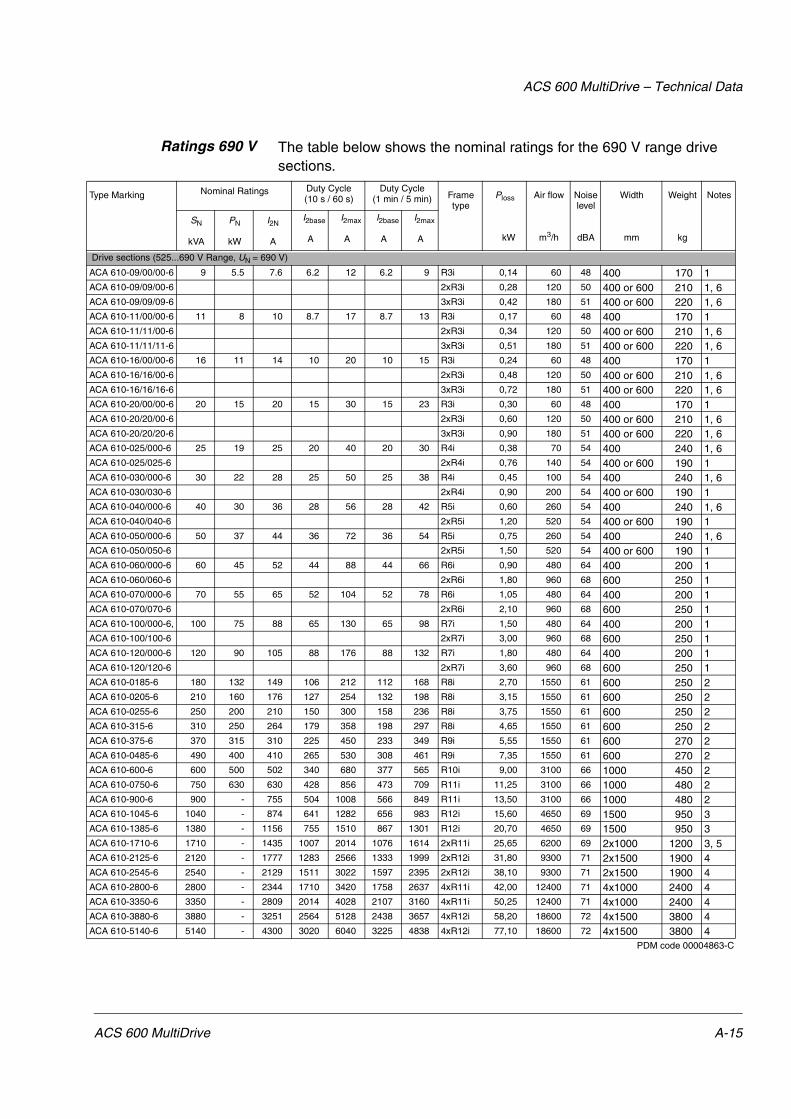
ACS 600 MultiDrive – Technical Data
Ratings 690 V The table below shows the nominal ratings for the 690 V range drive sections.
Type Marking Nominal Ratings Duty Cycle (10 s / 60 s)
Duty Cycle (1 min / 5 min) Frame
typePloss
kW
Air flow
m3/h
Noise level
dBA
Width
mm
Weight
kg
Notes
SN
kVA
PN
kW
I2N
A
I2base
A
I2max
A
I2base
A
I2max
A
Drive sections (525...690 V Range, UN = 690 V)
ACA 610-09/00/00-6 9 5.5 7.6 6.2 12 6.2 9 R3i 0,14 60 48 400 170 1 ACA 610-09/09/00-6 2xR3i 0,28 120 50 400 or 600 210 1, 6ACA 610-09/09/09-6 3xR3i 0,42 180 51 400 or 600 220 1, 6ACA 610-11/00/00-6 11 8 10 8.7 17 8.7 13 R3i 0,17 60 48 400 170 1ACA 610-11/11/00-6 2xR3i 0,34 120 50 400 or 600 210 1, 6ACA 610-11/11/11-6 3xR3i 0,51 180 51 400 or 600 220 1, 6ACA 610-16/00/00-6 16 11 14 10 20 10 15 R3i 0,24 60 48 400 170 1ACA 610-16/16/00-6 2xR3i 0,48 120 50 400 or 600 210 1, 6ACA 610-16/16/16-6 3xR3i 0,72 180 51 400 or 600 220 1, 6ACA 610-20/00/00-6 20 15 20 15 30 15 23 R3i 0,30 60 48 400 170 1ACA 610-20/20/00-6 2xR3i 0,60 120 50 400 or 600 210 1, 6ACA 610-20/20/20-6 3xR3i 0,90 180 51 400 or 600 220 1, 6ACA 610-025/000-6 25 19 25 20 40 20 30 R4i 0,38 70 54 400 240 1, 6ACA 610-025/025-6 2xR4i 0,76 140 54 400 or 600 190 1ACA 610-030/000-6 30 22 28 25 50 25 38 R4i 0,45 100 54 400 240 1, 6ACA 610-030/030-6 2xR4i 0,90 200 54 400 or 600 190 1ACA 610-040/000-6 40 30 36 28 56 28 42 R5i 0,60 260 54 400 240 1, 6ACA 610-040/040-6 2xR5i 1,20 520 54 400 or 600 190 1ACA 610-050/000-6 50 37 44 36 72 36 54 R5i 0,75 260 54 400 240 1, 6ACA 610-050/050-6 2xR5i 1,50 520 54 400 or 600 190 1ACA 610-060/000-6 60 45 52 44 88 44 66 R6i 0,90 480 64 400 200 1ACA 610-060/060-6 2xR6i 1,80 960 68 600 250 1ACA 610-070/000-6 70 55 65 52 104 52 78 R6i 1,05 480 64 400 200 1ACA 610-070/070-6 2xR6i 2,10 960 68 600 250 1ACA 610-100/000-6, 100 75 88 65 130 65 98 R7i 1,50 480 64 400 200 1ACA 610-100/100-6 2xR7i 3,00 960 68 600 250 1ACA 610-120/000-6 120 90 105 88 176 88 132 R7i 1,80 480 64 400 200 1ACA 610-120/120-6 2xR7i 3,60 960 68 600 250 1ACA 610-0185-6 180 132 149 106 212 112 168 R8i 2,70 1550 61 600 250 2ACA 610-0205-6 210 160 176 127 254 132 198 R8i 3,15 1550 61 600 250 2ACA 610-0255-6 250 200 210 150 300 158 236 R8i 3,75 1550 61 600 250 2ACA 610-315-6 310 250 264 179 358 198 297 R8i 4,65 1550 61 600 250 2ACA 610-375-6 370 315 310 225 450 233 349 R9i 5,55 1550 61 600 270 2ACA 610-0485-6 490 400 410 265 530 308 461 R9i 7,35 1550 61 600 270 2ACA 610-600-6 600 500 502 340 680 377 565 R10i 9,00 3100 66 1000 450 2ACA 610-0750-6 750 630 630 428 856 473 709 R11i 11,25 3100 66 1000 480 2ACA 610-900-6 900 - 755 504 1008 566 849 R11i 13,50 3100 66 1000 480 2ACA 610-1045-6 1040 - 874 641 1282 656 983 R12i 15,60 4650 69 1500 950 3ACA 610-1385-6 1380 - 1156 755 1510 867 1301 R12i 20,70 4650 69 1500 950 3ACA 610-1710-6 1710 - 1435 1007 2014 1076 1614 2xR11i 25,65 6200 69 2x1000 1200 3, 5ACA 610-2125-6 2120 - 1777 1283 2566 1333 1999 2xR12i 31,80 9300 71 2x1500 1900 4ACA 610-2545-6 2540 - 2129 1511 3022 1597 2395 2xR12i 38,10 9300 71 2x1500 1900 4ACA 610-2800-6 2800 - 2344 1710 3420 1758 2637 4xR11i 42,00 12400 71 4x1000 2400 4ACA 610-3350-6 3350 - 2809 2014 4028 2107 3160 4xR11i 50,25 12400 71 4x1000 2400 4ACA 610-3880-6 3880 - 3251 2564 5128 2438 3657 4xR12i 58,20 18600 72 4x1500 3800 4ACA 610-5140-6 5140 - 4300 3020 6040 3225 4838 4xR12i 77,10 18600 72 4x1500 3800 4
PDM code 00004863-C
ACS 600 MultiDrive A-15
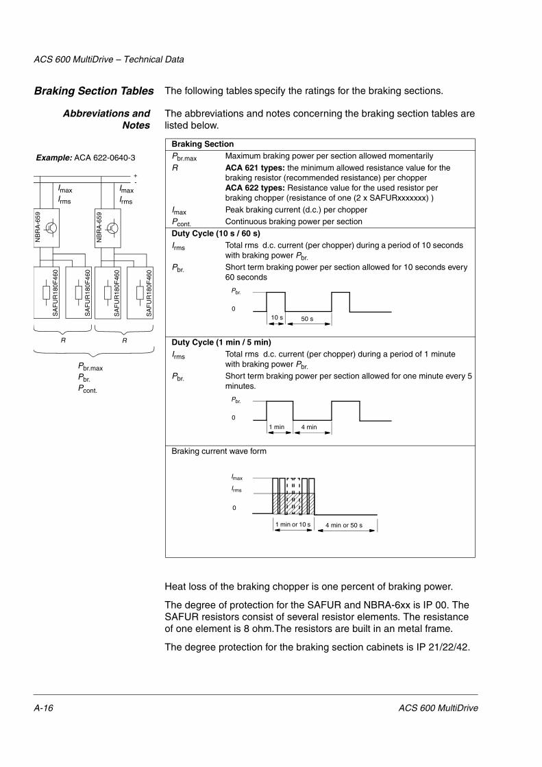
ACS 600 MultiDrive – Technical Data
Braking Section Tables The following tables specify the ratings for the braking sections.
Abbreviations andNotes
The abbreviations and notes concerning the braking section tables are listed below.
Heat loss of the braking chopper is one percent of braking power.
The degree of protection for the SAFUR and NBRA-6xx is IP 00. The SAFUR resistors consist of several resistor elements. The resistance of one element is 8 ohm.The resistors are built in an metal frame.
The degree protection for the braking section cabinets is IP 21/22/42.
Braking SectionPbr.max Maximum braking power per section allowed momentarily
R ACA 621 types: the minimum allowed resistance value for the braking resistor (recommended resistance) per chopperACA 622 types: Resistance value for the used resistor per braking chopper (resistance of one (2 x SAFURxxxxxxx) )
Imax Peak braking current (d.c.) per chopperPcont. Continuous braking power per section
Duty Cycle (10 s / 60 s)Irms Total rms d.c. current (per chopper) during a period of 10 seconds
with braking power Pbr.
Pbr. Short term braking power per section allowed for 10 seconds every 60 seconds
Duty Cycle (1 min / 5 min)Irms Total rms d.c. current (per chopper) during a period of 1 minute
with braking power Pbr.
Pbr. Short term braking power per section allowed for one minute every 5 minutes.
Braking current wave form
Example: ACA 622-0640-3
NB
RA
-659
SA
FU
R18
0F46
0
SA
FU
R18
0F46
0
ImaxIrms
R
NB
RA
-659
SA
FU
R18
0F46
0
SA
FU
R18
0F46
0
ImaxIrms
R
+-
Pbr.max Pbr.Pcont.
10 s 50 s
Pbr.
0
1 min 4 min
Pbr.
0
1 min or 10 s 4 min or 50 s
Imax
0
Irms
A-16 ACS 600 MultiDrive

ACS 600 MultiDrive – Technical Data
Ratings The table below shows the nominal ratings for the dynamic braking sections.
* The ACA 621 braking sections are not equipped with the braking resistors. They must be installed by the user.
Section Chopper Resistor Pbr.max
(kW)
R
(ohm)
Imax
(A)
Pcont.
(kW)
Duty Cycle (1min/5min)
Duty Cycle (10s/60s)
Pbr.(kW)
Irms(A)
Pbr.(kW)
Irms(A)
Braking sections (380...415 V Range,UN = 400 V)ACA 621-0210-3 NBRA658 * 230 1.7 384 70 230 355 230 355ACA 621-0320-3 NBRA659 * 353 1.2 545 96 303 468 353 545ACA 621-0640-3 2 x NBRA659 * 706 1.2 545 192 606 468 706 545ACA 621-0960-3 3 x NBRA659 * 1058 1.2 545 288 909 468 1059 545ACA 621-1280-3 4 x NBRA659 * 1411 1.2 545 384 1212 468 1412 545ACA 621-1600-3 5 x NBRA659 * 1764 1.2 545 480 1515 468 1765 545ACA 621-1920-3 6 x NBRA659 * 2117 1.2 545 576 1818 468 2118 545ACA 622-0210-3 NBRA658 2 x SAFUR210F575 230 1.7 384 42 130 200 224 345ACA 622-0320-3 NBRA659 2 x SAFUR180F460 353 1.2 545 54 167 257 287 444ACA 622-0640-3 2 x NBRA659 2 x (2 x SAFUR180F460) 706 1.2 545 108 333 257 575 444ACA 622-0960-3 3 x NBRA659 3 x (2 x SAFUR180F460) 1058 1.2 545 162 500 257 862 444ACA 622-1280-3 4 x NBRA659 4 x (2 x SAFUR180F460) 1411 1.2 545 216 667 257 1150 444ACA 622-1600-3 5 x NBRA659 5 x (2 x SAFUR180F460) 1764 1.2 545 270 833 257 1437 444ACA 622-1920-3 6 x NBRA659 6 x (2 x SAFUR180F460) 2117 1.2 545 324 1000 257 1724 444Braking sections (380...500 V Range,UN = 500 V)ACA 621-0260-5 NBRA658 * 268 2.15 380 81 268 331 268 331ACA 621-0400-5 NBRA659 * 403 1.43 571 109 317 391 403 498ACA 621-0800-5 2 x NBRA659 * 806 1.43 571 218 634 391 806 498ACA 621-1200-5 3 x NBRA659 * 1208 1.43 571 327 951 391 1209 498ACA 621-1600-5 4 x NBRA659 * 1611 1.43 571 436 1268 391 1612 498ACA 621-2000-5 5 x NBRA659 * 2014 1.43 571 545 1585 391 2015 498ACA 621-2400-5 6 x NBRA659 * 2417 1.43 571 654 1902 391 2418 498ACA 622-0260-5 NBRA658 2 x SAFUR125F500 268 2.00 408 36 111 137 192 237ACA 622-0400-5 NBRA659 2 x SAFUR200F500 403 1.35 605 54 167 206 287 355ACA 622-0800-5 2 x NBRA659 2 x (2 x SAFUR200F500) 806 1.35 605 108 333 206 575 355ACA 622-1200-5 3 x NBRA659 3 x (2 x SAFUR200F500) 1208 1.35 605 162 500 206 862 355ACA 622-1600-5 4 x NBRA659 4 x (2 x SAFUR200F500) 1611 1.35 605 216 667 206 1150 355ACA 622-2000-5 5 x NBRA659 5 x (2 x SAFUR200F500) 2014 1.35 605 270 833 206 1437 355ACA 622-2400-5 6 x NBRA659 6 x (2 x SAFUR200F500) 2417 1.35 605 324 1000 206 1724 355Braking sections (525...690 V Range,UN = 690 VACA 621-0400-6 NBRA669 * 404 2.72 414 119 298 267 404 361ACA 621-0800-6 2 x NBRA669 * 807 2.72 414 238 596 267 808 361ACA 621-1200-6 3 x NBRA669 * 1211 2.72 414 357 894 267 1212 361ACA 621-1600-6 4 x NBRA669 * 1615 2.72 414 476 1192 267 1616 361ACA 621-2000-6 5 x NBRA669 * 2019 2.72 414 595 1490 267 2020 361ACA 621-2400-6 6 x NBRA669 * 2422 2.72 414 714 1788 267 2424 361ACA 622-0400-6 NBRA669 2 x SAFUR200F500 404 1.35 835 54 167 149 287 257ACA 622-0800-6 2 x NBRA669 2 x (2 x SAFUR200F500) 807 1.35 835 108 333 149 287 257ACA 622-1200-6 3 x NBRA669 3 x (2 x SAFUR200F500) 1211 1.35 835 162 500 149 575 257ACA 622-1600-6 4 x NBRA669 4 x (2 x SAFUR200F500) 1615 1.35 835 216 667 149 862 257ACA 622-2000-6 5 x NBRA669 5 x (2 x SAFUR200F500) 2019 1.35 835 270 833 149 1150 257ACA 622-2400-6 6 x NBRA669 6 x (2 x SAFUR200F500) 2422 1.35 835 324 2000 149 1724 257
PDM code 00017952-C
ACS 600 MultiDrive A-17

ACS 600 MultiDrive – Technical Data
Dimensions, Air Flowand Noise
The dimensions, air flows and noise levels for braking sections are given below. The depth of the cabinet is 600 mm. An extra 200 mm wide cabinet is added for top exit ACA 621 units.
Section Heigth(mm)
Width(mm)
Weight(kg)
Noise(dB)
Air flow(m3/h)
Braking sections (380...415 V Range,UN = 400 V)ACA 621-0210-3 2065 400 110 64 660ACA 621-0320-3 2065 400 110 64 660ACA 621-0640-3 2065 800 220 67 1320ACA 621-0960-3 2065 1200 330 68 1980ACA 621-1280-3 2065 1600 440 69 2640ACA 621-1600-3 2065 2000 550 70 3300ACA 621-1920-3 2065 2400 660 71 3960ACA 622-0210-3 2078 1200 340 66 2500ACA 622-0320-3 2078 1200 340 66 2500ACA 622-0640-3 2078 2400 680 69 5000ACA 622-0960-3 2078 3600 1020 70 7500ACA 622-1280-3 2078 4800 1360 71 10000ACA 622-1600-3 2078 6000 1700 72 12500ACA 622-1920-3 2078 7200 2040 73 15000Braking sections (380...500 V Range,UN = 500 V)ACA 621-0260-5 2065 400 110 64 660ACA 621-0400-5 2065 400 110 64 660ACA 621-0800-5 2065 800 220 67 1320ACA 621-1200-5 2065 1200 330 68 1980ACA 621-1600-5 2065 1600 440 69 2640ACA 621-2000-5 2065 2000 550 70 3300ACA 621-2400-5 2065 2400 660 71 3960ACA 622-0260-5 2078 1200 340 66 2500ACA 622-0400-5 2078 1200 340 66 2500ACA 622-0800-5 2078 2400 680 69 5000ACA 622-1200-5 2078 3600 1020 70 7500ACA 622-1600-5 2078 4800 1360 71 10000ACA 622-2000-5 2078 6000 1700 72 12500ACA 622-2400-5 2078 7200 2040 73 15000Braking sections (525...690 V Range,UN = 690 VACA 621-0400-6 2065 400 110 64 660ACA 621-0800-6 2065 400 110 67 660ACA 621-1200-6 2065 800 220 68 1320ACA 621-1600-6 2065 1200 330 69 1980ACA 621-2000-6 2065 1600 440 70 2640ACA 621-2400-6 2065 2000 550 71 3300ACA 622-0400-6 2078 1200 340 66 2500ACA 622-0800-6 2078 1200 340 69 5000ACA 622-1200-6 2078 2400 680 70 7500ACA 622-1600-6 2078 3600 1020 71 10000ACA 622-2000-6 2078 4800 1360 72 12500ACA 622-2400-6 2078 6000 1700 73 15000
PDM code 00017952-C
A-18 ACS 600 MultiDrive

ACS 600 MultiDrive – Technical Data
Cabinet The cabinet, degrees of protection and free space requirements of ACS 600 MultiDrive are listed below.
1) IP 21 = standard, R = air outlet duct2) 200 between cabinets when installed back to back
IP 54 R Air Outlet DuctConnection
The dimensions of the duct adjoining to IP 54 R cabinet are below.
ACx 600 Type Enclosure Degree of Protection
Spaceabove mm
Spacebelow mm
Space onleft/right
mm
Space infront/back
mm
ACS 600 MultiDrive CabinetIP 21, IP 22, IP 42, IP 54 R1)
500 0 0 200/1002)
Cabinet Widthmm
Duct Ømm
400 250
600 310
800 310
1000 2x310
1500 3x310
Common Cabinet Door Opening
ACS 600 MultiDrive A-19
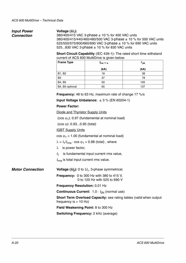
ACS 600 MultiDrive – Technical Data
Input Power Connection
Voltage (U1):380/400/415 VAC 3-phase ± 10 % for 400 VAC units380/400/415/440/460/480/500 VAC 3-phase ± 10 % for 500 VAC units525/550/575/600/660/690 VAC 3-phase ± 10 % for 690 VAC units525...830 VAC 3-phase ± 10 % for 830 VAC units
Short Circuit Capability (IEC 439-1): The rated short time withstand current of ACS 600 MultiDrive is given below.
Frequency: 48 to 63 Hz, maximum rate of change 17 %/s
Input Voltage Unbalance: ± 3 % (EN 60204-1)
Power Factor:
Diode and Thyristor Supply Units
(cos �1): 0.97 (fundamental at nominal load)
(cos �): 0.93...0.95 (total)
IGBT Supply Units
cos �1 = 1.00 (fundamental at nominal load)
��= I1/Irms · cos �1 > 0.98 (total) , where
�����is power factor,
I1 is fundamental input current rms value,
Irms is total input current rms value.
Motor Connection Voltage (U2): 0 to U1, 3-phase symmetrical.
Frequency: 0 to 300 Hz with 380 to 415 V, 0 to 120 Hz with 525 to 690 V
Frequency Resolution: 0.01 Hz
Continuous Current: 1.0 · I2N (normal use)
Short Term Overload Capacity: see rating tables (valid when output frequency is > 10 Hz)
Field Weakening Point: 8 to 300 Hz
Switching Frequency: 2 kHz (average)
Frame Type Icw / 1 s
(kA)
I pk
(kA)
B1, B2 18 38
B3 37 78
B4, B5 50 105
B4, B5 optional 65 137
A-20 ACS 600 MultiDrive

ACS 600 MultiDrive – Technical Data
Maximum Recommended Motor Cable Length: For cables longer than 500 metres (cumulative length in case of parallel connected motors), an ABB representative must be consulted. With pulse encoder speed measurement maximum cable length is 300 m. With du/dt filters refer to du/dt Installation Guide (code: 58933368). For additional EMC requirements on cable length refer to section CE Marking below.
Cable Types: The tables below give the copper and aluminium cable types for different load currents (ILmax). A correction factor of K = 0.70 has been used (max. 9 cables laid on a cable ladder side by side, three ladders on top of each other, ambient temperature 30 °C (86 °F), EN 60204-1 and IEC 364-5-523)
Bearings of over 90 kW Motors: Insulated bearing at non-driven end is recommended.
COPPER CABLES WITHA CONCENTRIC COPPER SCREEN
ALUMINIUM CABLES WITHA CONCENTRIC COPPER SCREEN
ILmax[A]
Cable TypeDiameter
[mm]ILmax[A]
Cable TypeDiameter
[mm]13 3×1.5 + 1.5 13 69 3×35Al + 10Cu 2618 3×2.5 + 2.5 14 83 3×50Al + 15Cu 2924 3×4 + 4 16 107 3×70Al + 21Cu 3230 3×6 + 6 18 130 3×95Al + 29Cu 3842 3×10 + 10 21 151 3×120Al + 41Cu 4156 3×16 + 16 23 174 3×150Al + 41Cu 4471 3×25 + 16 24 199 3×185Al + 57Cu 4988 3×35 + 16 26 214 2 × (3×70Al + 21Cu) 2 × 32
107 3×50 + 25 29 235 3×240Al + 72Cu 54137 3×70 + 35 32 260 2 × (3×95Al + 29Cu) 2 × 38167 3×95 + 50 38 302 2 × (3×120Al + 41Cu) 2 × 41193 3×120 + 70 41 348 2 × (3×150Al + 41Cu) 2 × 44223 3×150 + 70 44 398 2 × (3×185Al + 57Cu) 2 × 49255 3×185 + 95 50 470 2 × (3×240Al + 72Cu) 2 × 54274 2 × (3×70 + 35) 2 × 32 522 3 × (3×150Al + 41Cu) 3 × 44301 3×240 + 120 55 597 3 × (3×185Al + 57Cu) 3 × 49334 2 × (3×95 + 50) 2 × 38 696 4 × (3×150Al + 41Cu) 4 × 44386 2 × (3×120 + 70) 2 × 41 705 3 × (3×240Al + 72Cu) 3 × 54446 2 × (3×150 + 70) 2 × 44 796 4 × (3×185Al + 57Cu) 4 × 49510 2 × (3×185 + 95) 2 × 50 940 4 × (3×240Al + 72Cu) 4 × 54579 3 × (3×120 + 70) 3 × 41 995 5 × (3×185Al + 57Cu) 5 × 49602 2 × (3×240 + 120) 2 × 55 1175 5 × (3×240Al + 72Cu) 5 × 54669 3 × (3×150 + 70) 3 × 44765 3 × (3×185 + 95) 3 × 50772 4 × (3×120 + 70) 4 × 41892 4 × (3×150 + 70) 4 × 44903 3 × (3×240 + 120) 3 × 55
1020 4 × (3×185+ 95) 4 × 50
ACS 600 MultiDrive A-21

ACS 600 MultiDrive – Technical Data
Efficiency and Cooling Method
Efficiency: Approximately 98 % at nominal power level and frequency. For units equipped with IGBT supply unit approximately 96 %.
Cooling Method: Internal fan, flow direction from the bottom to the top
Ambient Conditions Environmental limits of the ACS 600 MultiDrive frequency converters are given below.
1) At sites over 1000 m above sea level, the maximum output current is derated as follows.
Imax = I N40C · (100 % - 1 % · (h - 1000 m)/(100 m) + 1.5 % · (40 °C - Tamb))
where
h altitude above sea level
I N40C ACS 600 nominal current at 40 °C
Tamb maximum ambient temperature.
Note: Imax < I N40C and Tamb < 40 °C. At 2000...4000 m optional “varistors” are needed.2) If the ambient temperature is higher than +40 °C (+35 °C), the output capacity of the ACx 600 decreases. The output current is calculated by multiplying the current given in the rating table by the derating factor.
Condition Operation installed for stationary use
Storagein the protective package
Transportationin the protective package
Installation Site Altitude
Nominal output power at 0 to 1000 m above sea level 1)
- -
Air Temperature 0 to +40 °C 2) (IP 21/22/42) 0 to +35 °C 2) (IP 54R)
-40 to +70 °C -40 to +70 °C
Relative Humidity 5 to 95 % Max. 95 % Max. 95 %
No condensation allowed. Maximum allowed relative humidity is 60 % in the presence of corrosive gases.
Contamination Levels(IEC 721-3-3)
No conductive dust allowed.
Boards without coating: Chemical gases: Class 3C1Solid particles: Class 3S2
Boards with coating: Chemical gases: Class 3C2Solid particles: Class 3S2
Boards without coating: Chemical gases: Class 1C2Solid particles: Class 1S3
Boards with coating: Chemical gases: Class 1C2Solid particles: Class 1S3
Boards without coating: Chemical gases: Class 2C2Solid particles: Class 2S2
Boards with coating: Chemical gases: Class 2C2Solid particles: Class 2S2
Atmospheric Pressure
70 to 106 kPa 70 to 106 kPa 60 to 106 kPa
Vibration(IEC 68-2-6)
Max. 0.3 mm (2 to 9 Hz),max. 1 m/s2 (9 to 200 Hz) sinusoidal
Max. 1.5 mm (2 to 9 Hz), max. 5 m/s2 (9 to 200 Hz) sinusoidal
Max. 3.5 mm (2 to 9 Hz), max. 15 m/s2 (9 to 200 Hz) sinusoidal
Shock(IEC 68-2-29)
Not allowed Max. 100 m/s2, 11 ms Max. 100 m/s2, 11 ms
Free Fall Not allowed 250 mm (weight under 100 kg)100 mm (weight over 100 kg)
250 mm (weight under 100 kg)100 mm (weight over 100 kg)
A-22 ACS 600 MultiDrive

ACS 600 MultiDrive – Technical Data
Derating factor for degree of protection IP 21/22/42:
• Above +40 °C, the rated output current is decreased 1.5 % for every additional 1 °C (up to +50 °C).
• Example 1. If the ambient temperature is 50 °C the derating factor is
100 % - 1.5 · 10 °C = 85 % or 0.85. The output current is then 0.85 · I2N (or
I2base or I2max).
Derating Diagram: the effect of ambient temperature on the ACS 600 MultiDrive continuous load capacity.
%°C
100
95
85
80
90
36 40
Current (%)
T (°C)44 48 52
-1.5 % per each + °C
IP 21/22/42IP 54R
ACS 600 MultiDrive A-23

ACS 600 MultiDrive – Technical Data
Fuses The ultrarapid fuses of the ACS 600 MultiDrive are given below. Equivalent fuses from other manufacturers can also be used. Only ultra rapid fuses guarantee proper protection for the rectifier semiconductors. UN and IN stand for the nominal voltage and the nominal current of the fuse.
AC Fuses Below are listed a.c. fuses (Bussmann) used in the supply section of ACS 600 MultiDrive frames B1, B2 and B3.
Thyristor Supply Section
Fuse Diode Supply (6-pulse and 12-pulse)
Section
Fuse
UN
(V)IN(A)
Pre-arching Integral
(A2s)
Type Size UN
(V)IN(A)
Pre-arching Integral
(A2s)
Type Size
ACA 632-0015-31-xxACA 632-0020-51-xx
660 50 115 170M1564 000
ACA 632-0030-31-xxACA 632-0035-51-xx
660 80 380 170M1566 000
ACA 632-0040-31-xxACA 632-0050-51-xx
660 125 1200 170M1568 000
ACA 632-0070-31-xxACA 632-0090-51-xx
660 160 2300 170M1569 000
ACA 632-0140-31-xxACA 632-0175-51-xx
660 315 4950 170M5806 2 ACA 631-0140-31-xxACA 633-0280-31-xxACA 631-0175-51-xx
660 315 4950 170M5806 2
ACA 632-0200-31-xxACA 634-0200-31-xxACA 632-0250-51-xxACA 634-0250-51-xx
660 450 15500 170M5371 2SHT ACA 631-0200-31-xxACA 633-0400-31-xxACA 631-0250-51-xx
690 500 21500 170M5810 2
ACA 632-0300-31-xxACA 632-0375-51-xx
660 700 44500 170M6206 3SHT ACA 631-0300-31-xxACA 633-0600-31-xxACA 631-0375-51-xx
690 800 69500 170M6812 3
ACA 632-0420-31-xxACA 634-0420-31-xxACA 636-0800-31-xxACA 638-0800-31-xxACA 639-0800-31-xxACA 632-0525-51-xxACA 636-1000-51-xxACA 638-1000-51-xxACA 639-1000-51-xx
660 900 100000 170M6207 3SHT ACA 631-0420-31-xxACA 633-0840-31-xxACA 631-0525-51-xx
660 900 100000 170M6207 3SHT
ACA 632-0090-61-xxACA 633-0180-61-xxACA 632-0175-61-xxACA 633-0350-61-xx
1250 200 3800 170M4700 1SHT ACA 631-0090-61-xx 690 200 1200 170M5804 2
ACA 632-0250-61-xx 1250 315 13000 170M5403 2SHT ACA 631-0175-61-xx 690 200 1200 170M5804 2ACA 632-0375-61-xx 1250 400 23000 170M5404 2SHT ACA 631-0250-61-xx 690 350 10000 170M3818 1*ACA 632-0525-61-xxACA 636-1000-61-xx
1250 630 83500 170M6205 3SHT ACA 631-0375-61-xx 690 630 41000 170M5812 2
ACA 631-0525-61-xx 690 800 69500 170M6812 3ACA 633-0180-61-xx 690 200 1200 170M5804 2ACA 633-0350-61-xx 690 200 1200 170M5804 2ACA 633-0500-61-xx 690 350 10000 170M3818 1*ACA 633-0750-61-xx 690 630 41000 170M5812 2ACA 633-1050-61-xx 690 800 69500 170M6812 3
PDM code 00010321-K
A-24 ACS 600 MultiDrive

ACS 600 MultiDrive – Technical Data
Branch Fuses Frame B4 to B5 diode and thyristor supply modules employ internal branch fuses instead of input or output fuses. The table lists the applicable Bussmann types.
Branch Fuses for Frame B4 and B5 Supply ModulesSupply Module
TypeUN(V)
IN(A)
Pre-arching Integral
(A2s) Type Size
ACN 654 0855 5ACN 664 0855 5ACN 684 0855 5
660 900 100000 170M6163 3/110
ACN 654 1405 5ACN 664 1405 5ACN 684 1405 5
660 1500 460000 170M6168 3/110ACN 654 2120 5ACN 664 2120 5ACN 684 2120 5ACN 654 2600 5ACN 664 2600 5ACN 684 2600 5ACN 654 0855 6ACN 664 0855 6ACN 684 0855 6
1250 630 83500 170M6144 3/110
ACN 654 1405 6ACN 664 1405 6ACN 684 1405 6
1250 1100 575000 170M6149 3/110ACN 654 2600 6ACN 664 2600 6ACN 684 2600 6ACN 654 3600 6ACN 664 3600 6ACN 684 3600 6
1110 1400 1250000 170M6151 3/110
ACN 654 1685 8ACN 664 1685 8
1250 1100 575000 170M6149 3/110ACN 654 3100 8ACN 664 3100 8ACN 654 3520 8ACN 664 3520 8
1110 1400 1250000 170M6151 3/110ACN 654 4310 8ACN 664 4310 8
PDM code 00004021-B
ACS 600 MultiDrive A-25
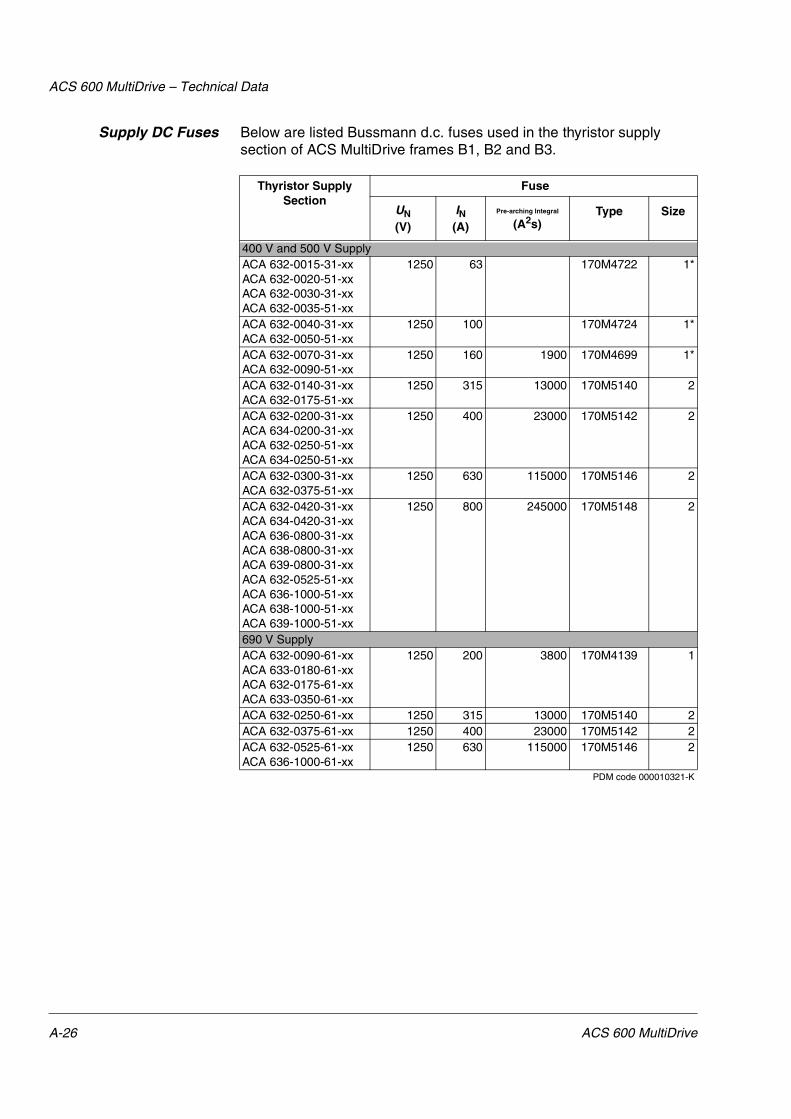
ACS 600 MultiDrive – Technical Data
Supply DC Fuses Below are listed Bussmann d.c. fuses used in the thyristor supply section of ACS MultiDrive frames B1, B2 and B3.
Thyristor Supply Section
Fuse
UN(V)
IN(A)
Pre-arching Integral
(A2s)Type Size
400 V and 500 V SupplyACA 632-0015-31-xxACA 632-0020-51-xxACA 632-0030-31-xxACA 632-0035-51-xx
1250 63 170M4722 1*
ACA 632-0040-31-xxACA 632-0050-51-xx
1250 100 170M4724 1*
ACA 632-0070-31-xxACA 632-0090-51-xx
1250 160 1900 170M4699 1*
ACA 632-0140-31-xxACA 632-0175-51-xx
1250 315 13000 170M5140 2
ACA 632-0200-31-xxACA 634-0200-31-xxACA 632-0250-51-xxACA 634-0250-51-xx
1250 400 23000 170M5142 2
ACA 632-0300-31-xxACA 632-0375-51-xx
1250 630 115000 170M5146 2
ACA 632-0420-31-xxACA 634-0420-31-xxACA 636-0800-31-xxACA 638-0800-31-xxACA 639-0800-31-xxACA 632-0525-51-xxACA 636-1000-51-xxACA 638-1000-51-xxACA 639-1000-51-xx
1250 800 245000 170M5148 2
690 V SupplyACA 632-0090-61-xxACA 633-0180-61-xxACA 632-0175-61-xxACA 633-0350-61-xx
1250 200 3800 170M4139 1
ACA 632-0250-61-xx 1250 315 13000 170M5140 2ACA 632-0375-61-xx 1250 400 23000 170M5142 2ACA 632-0525-61-xxACA 636-1000-61-xx
1250 630 115000 170M5146 2
PDM code 000010321-K
A-26 ACS 600 MultiDrive

ACS 600 MultiDrive – Technical Data
Drive Unit DC Fuses Below are listed Bussmann fuses used in the inverters of ACS MultiDrive.
Drive Section Frame
Fuse Drive Section Frame/Type
Fuse
UN(V)
Size IN(A)
Pre-arching Integral
(A2s)Type UN
(V)Size IN
(A)
Pre-arching Integral
(A2s)Type
415 V and 500 V Range 690 V Range
R2i 660V 000 25 19 170M1561 R3i:ACA-610-0009-6ACA-610-0011-6
1000V 00 25 29 170M2674
R3i 660V 000 50 115 170M1564 R3i:ACA-610-0016-6ACA-610-0020-6
1000V 00 35 69 170M2676
R4i 660V 000 80 380 170M1566 R4i 1000V 00 63 380 170M2679R5i 660V 000 160 2300 170M1569 R5i 1000V 00 80 815 170M2680R6i 660V 000 200 4200 170M1570 R6i 1000V 00 125 3000 170M2682R7i 660V 1* 350 10000 170M3818 R7i 1250V 1SHT 200 3800 170M4700R8iR10i
660V 3 630 31000 170M6810 R8i:ACA-610-0185-6ACA-610-0205-6
1250V 3SHT 315 9500 170M6301
R9iR11i2xR114xR11iR12i2xR12i
660V 3 1000 140000 170M6814 R8i:ACA-610-0255-6ACA-610-0315-6R10i
1250V 3SHT 400 19500 170M6303
R9iR11i4xR11iR12i2xR12i4xR12i
1250V 3SHT 630 83500 170M6205
PDM code 00008855-F
ACS 600 MultiDrive A-27

ACS 600 MultiDrive – Technical Data
Braking Section DCFuses
The d.c. fuses (Bussmann) for the braking sections are listed below.
Dynamic Braking SectionFuse
UN(V)
IN(A)
Pre-arching Integral
(A2s)Type Size
400 V RangeACA 621-0210-3 1000–1250 400 23000 170M 5142 2/110ACA 621-0320-3...-1920-3 1000–1250 630 115000 170M 5146 2/110ACA 622-0210-3 1000–1250 400 23000 170M 5142 2/110ACA 622-0320-3...-1920-3 1000–1250 630 115000 170M 5146 2/110500 V RangeACA 621-0260-5 1000–1250 400 23000 170M 5142 2/110ACA 621-0400-5...-2400-3 1000–1250 630 115000 170M 5146 2/110ACA 622-0260-5 1000–1250 400 23000 170M 5142 2/110ACA 622-0400-5...-2400-5 1000–1250 630 115000 170M 5146 2/110690 V RangeACA 621-0400-6...-2400-6 1000–1250 630 115000 170M 5146 2/110ACA 622-0400-6...-2400-6 1000–1250 630 115000 170M 5146 2/110
PDM code 00025310-A
A-28 ACS 600 MultiDrive

ACS 600 MultiDrive – Technical Data
Power Cable Entries Notes concerning the cable entry tables are below.
Tightening Torque Tightening torques for screw connections (applicable to zinc and chrome platings and screw strength class 8.8) are presented below.
* valid also for greased screws
Marking Below is explained the way cable connections are marked in the following tables. The terminals accept cable lugs according to DIN 46234 for copper cables and DIN 46329 for aluminium cables.
Screw Torque (Nm) *
Soft aluminium Alloyed aluminium and copper
M5 3.5 3.5
M6 6 9
M8 17 20
M10 35 40
M12 55 70
M16 130 180
4x(13x18)Number of connection
Connection hole (max. screw) diameter or
holes in terminal
Note: Cable lugs can also be fastened using screws one size down from the hole size. Example: A cable lug with a hole diameter of 12.5 mm can be fastened with either a M12 or a M10 bolt.
dimensions in mm
ACS 600 MultiDrive A-29

ACS 600 MultiDrive – Technical Data
Diode Supply Sections The connection holes for cable lugs and bus duct are presented below.
Thyristor SupplySection: Terminal Block
Connection
The maximum cable size accepted by the terminal block of frame type B1 is given below.
Type Holes for cable lugs per phase
Number of cable entries at bottom (diameter 60 mm)
Bottom plate opening dimensions
(mm)
Number of cable entries at top (diameter 60 mm)
Holes for bus duct connection
UN = 400V (380V...415V)
ACA 631-0140-3 2x14 3 310x240 3 -ACA 631-0200-3 2x14 3 310x240 3 -ACA 631-0300-3 4x14 6 502x280 6 -ACA 631-0420-3 4x14 6 502x280 6 -ACA 631-0680-3 4x(13x18) 12 502x280 12 4x(13x24)ACA 631-1120-3 8x(13x18) 12 502x280 12 4x(13x24)ACA 631-1700-3 12x(13x18) 18 502x280 18 4x(13x24)ACA 631-2100-3 12x(13x18) 18 502x280 18 4x(13x24)UN = 500V (380V...500V)
ACA 631-0175-5 2x14 3 310x240 3 -ACA 631-0250-5 2x14 3 310x240 3 -ACA 631-0375-5 4x14 6 502x280 6 -ACA 631-0525-5 4x14 6 502x280 6 -ACA 631-0850-5 4x(13x18) 12 502x280 12 4x(13x24)ACA 631-1400-5 8x(13x18) 12 502x280 12 4x(13x24)ACA 631-2120-5 12x(13x18) 18 502x280 18 4x(13x24)ACA 631-2600-5 12x(13x18) 18 502x280 18 4x(13x24)UN = 690V (525V...690V)
ACA 631-0090-6 2x14 3 310x240 3 -ACA 631-0175-6 2x14 3 310x240 3 -ACA 631-0250-6 2x14 3 310x240 3 -ACA 631-0375-6 4x14 6 502x280 6 -ACA 631-0525-6 4x14 6 502x280 6 -ACA 631-0850-6 4x(13x18) 12 502x280 12 4x(13x24)ACA 631-1400-6 8x(13x18) 12 502x280 12 4x(13x24)ACA 631-2600-6 12x(13x18) 18 502x280 18 4x(13x24)ACA 631-3600-6 12x(13x18) 18 502x280 18 4x(13x24)
Types:ACA 632-0015-3 ACA 632-0030-3ACA 632-0040-3ACA 632-0070-3ACA 632-0020-5ACA 632-0035-5ACA 632-0050-5ACA 632-0090-5
Frame Size
B1
Cable Size Tightening Torgue
Cable entries at bottom (diameter 60 mm)
Bottom plate opening dimensions
Cable entries at top (diameter 60 mm)
mm2 AWG Nm pcs mm pcs
70 2/0 8 3 310x240 3
A-30 ACS 600 MultiDrive

ACS 600 MultiDrive – Technical Data
Thyristor SupplySection: Busbar / Bus
Duct Connection
The connection holes for cable lugs and bus duct are presented below.
Type Holes for cable lugs per phase
Number of cable entries at bottom (diameter 60 mm)
Bottom plate opening dimensions
(mm)
Number of cable entries at top (diameter 60 mm)
Holes for bus duct connection
UN = 400V (380V...415V)
ACA 632-0140-3 2x14 3 310x240 3 -ACA 632-0200-3 2x14 3 310x240 3 -ACA 632-0300-3 4x14 6 502x280 6 -ACA 632-0420-3 4x14 6 502x280 6 -ACA 632-0680-3 4x(13x18) 12 502x280 12 4x(13x24)ACA 632-1120-3 8x(13x18) 12 502x280 12 4x(13x24)ACA 632-1700-3 12x(13x18) 18 502x280 18 4x(13x24)ACA 632-2100-3 12x(13x18) 18 502x280 18 4x(13x24)UN = 500V (380V...500V)
ACA 632-0175-5 2x14 3 310x240 3 -ACA 632-0250-5 2x14 3 310x240 3 -ACA 632-0375-5 4x14 6 502x280 6 -ACA 632-0525-5 4x14 6 502x280 6 -ACA 632-0850-5 4x(13x18) 12 502x280 12 4x(13x24)ACA 632-1400-5 8x(13x18) 12 502x280 12 4x(13x24)ACA 632-2120-5 12x(13x18) 18 502x280 18 4x(13x24)ACA 632-2600-5 12x(13x18) 18 502x280 18 4x(13x24)UN = 690V (525V...690V)
ACA 632-0090-6 2x14 3 310x240 3 -ACA 632-0175-6 2x14 3 310x240 3 -ACA 632-0250-6 2x14 3 310x240 3 -ACA 632-0375-6 4x14 6 502x280 6 -ACA 632-0525-6 4x14 6 502x280 6 -ACA 632-0850-6 4x(13x18) 12 502x280 12 4x(13x24)ACA 632-1400-6 8x(13x18) 12 502x280 12 4x(13x24)ACA 632-2600-6 12x(13x18) 18 502x280 18 4x(13x24)ACA 632-3600-6 12x(13x18) 18 502x280 18 4x(13x24)UN = 830V (525V...830V)
ACA 632-1680-8 4x(13x18) 12 502x280 12 4x(13x24)ACA 632-3100-8 12x(13x18) 18 502x280 18 4x(13x24)ACA 632-3520-8 12x(13x18) 18 502x280 18 4x(13x24)ACA 632-4310-8 12x(13x18) 18 502x280 18 4x(13x24)
ACS 600 MultiDrive A-31

ACS 600 MultiDrive – Technical Data
Drive Sections:Terminal Block
Connection
The maximum cable sizes accepted by the terminal block for motor and brake cable connection (terminals U2, V2, W2, PE, UDC+, UDC-) of frame types R2i to R5i are given below.
Drive Sections: BusbarConnection
The connection holes for motor and brake cable lugs (terminals U2, V2, W2, PE, UDC+, UDC-) of the drive sections are presented below.
Frame Cable Size Tightening Torgue
Cable entries at bottom (diameter 60 mm)
Bottom plate opening dimensions
Cable entries at top (diameter 60 mm)Solid Stranded
mm2 mm2 AWG Nm pcs mm pcs
R2i 10 6 8 1.5...1.8 3 110x235 3R3i 16 10 6 1.5...1.8 3 110x235 3R4i 25 16 4 1.5...1.8 3 110x235 3R5i 35 25 2 4.0...4.5 3 110x235 3
Type Holes for cable lugs per phase
Number of cable entries at bottom (diameter 60 mm)
Bottom plate opening dimensions
(mm)
Number of cable entries at top (diameter 60 mm)
380V, 400V, 415V
ACA 610-0060-3 1x(13x18) 3 110x235 3ACA 610-0070-3 1x(13x18) 3 110x235 3ACA 610-0100-3 1x(13x18) 3 110x235 3ACA 610-0120-3 1x(13x18) 3 110x235 3ACA 610-0185-3 4x(13x18) 6 270x511 6ACA 610-0225-3 4x(13x18) 6 270x511 6ACA 610-0265-3 4x(13x18) 6 270x511 6ACA 610-0335-3 4x(13x18) 6 270x511 6ACA 610-0405-3 4x(13x18) 6 270x511 6ACA 610-0500-3 6x(13x18) 6 270x911 6ACA 610-0630-3 6x(13x18) 6 270x911 6ACA 610-0760-3 6x(13x18) 6 270x911 6ACA 610-0935-3 8x(13x18) 12 195x501 12ACA 610-1125-3 8x(13x18) 12 195x501 12ACA 610-1440-3 16x(13x18) 18 270x711 18ACA 610-1775-3 16x(13x18) 18 270x711 18ACA 610-2145-3 16x(13x18) 18 270x711 18ACA 610-2340-3 16x(13x18) 18 270x711 18ACA 610-2820-3 16x(13x18) 18 270x711 18440V, 460V, 500V
ACA 610-0070-5 1x(13x18) 3 110x235 3ACA 610-0100-5 1x(13x18) 3 110x235 3ACA 610-0120-5 1x(13x18) 3 110x235 3ACA 610-0140-5 1x(13x18) 3 110x235 3ACA 610-0205-5 4x(13x18) 6 270x511 6ACA 610-0255-5 4x(13x18) 6 270x511 6ACA 610-0325-5 4x(13x18) 6 270x511 6ACA 610-0395-5 4x(13x18) 6 270x511 6
A-32 ACS 600 MultiDrive

ACS 600 MultiDrive – Technical Data
ACA 610-0495-5 4x(13x18) 6 270x511 6ACA 610-0610-5 6x(13x18) 6 270x911 6ACA 610-0770-5 6x(13x18) 6 270x911 6ACA 610-0935-5 6x(13x18) 6 270x911 6ACA 610-1095-5 8x(13x18) 12 195x501 12ACA 610-1385-5 8x(13x18) 12 195x501 12ACA 610-1760-5 16x(13x18) 18 270x711 18ACA 610-2165-5 16x(13x18) 18 270x711 18ACA 610-2625-5 16x(13x18) 18 270x711 18ACA 610-2850-5 16x(13x18) 18 270x711 18ACA 610-3450-5 16x(13x18) 18 270x711 18575V, 660V, 690V
ACA 610-0060-6 1x(13x18) 3 110x235 3ACA 610-0070-6 1x(13x18) 3 110x235 3ACA 610-0100-6 1x(13x18) 3 110x235 3ACA 610-0120-6 1x(13x18) 3 110x235 3ACA 610-0185-6 4x(13x18) 6 270x511 6ACA 610-0205-6 4x(13x18) 6 270x511 6ACA 610-0255-6 4x(13x18) 6 270x511 6ACA 610-0315-6 4x(13x18) 6 270x511 6ACA 610-0375-6 4x(13x18) 6 270x511 6ACA 610-0485-6 6x(13x18) 6 270x911 6ACA 610-0600-6 6x(13x18) 6 270x911 6ACA 610-0750-6 6x(13x18) 6 270x911 6ACA 610-0900-6 6x(13x18) 6 270x911 6ACA 610-1045-6 8x(13x18) 12 195x501 12ACA 610-1385-6 8x(13x18) 12 195x501 12ACA 610-1710-6 8x(13x18) 12 195x501 12ACA 610-2125-6 16x(13x18) 18 270x711 18ACA 610-2545-6 16x(13x18) 18 270x711 18ACA 610-2800-6 16x(13x18) 18 270x711 18ACA 610-3350-6 16x(13x18) 18 270x711 18ACA 610-3880-6 32x(13x18) 18 270x911 18ACA 610-5140-6 32x(13x18) 18 270x911 18
Type Holes for cable lugs per phase
Number of cable entries at bottom (diameter 60 mm)
Bottom plate opening dimensions
(mm)
Number of cable entries at top (diameter 60 mm)
ACS 600 MultiDrive A-33

ACS 600 MultiDrive – Technical Data
NIOC Board Specifications
Data of the external control connection board NIOC-01 of the ACS 600 product family are given below. NIOC-01 board is included in the drive section of the ACS 600 MultiDrive. For external control connections of the supply section, refer to Diode/Thyristor/IGBT Supply Sections User’s Manual. For external control connections of the control section, refer to Common Drive Control Manuals.
ACS/ACC/ACP 600, ACS 600 MultiDriveNIOC-01 Board
Analogue Inputs
The advantage of the differential analogue input is that the earth potential of the device or transmitter sending an analogue signal can differ up to ± 15 V from the earth potential of the ACx 600 chassis without disturbing the signal. Differential input also efficiently attenuates common mode disturbances coupled to control cables.
ACS 600, ACS 600 MultiDrive: Two Programmable Differential Current Inputs: 0 (4) to 20 mA, Rin = 100 �
ACC 600: Two Differential Current Inputs: 0 to 20 mA, Rin = 100 �
ACP 600: One Programmable Differential Current Input: 0 to 20 mA, Rin = 100 �
ACS/ACP 600, ACS 600 MultiDrive: One Programmable Differential Voltage Input: ACS 600: 0 (2) to 10 V, Rin > 200 k�; ACP 600: 0 to 10 V, Rin > 200 k�
ACC 600: One Differential Voltage Input: 0 to 10 V, Rin > 200 k�
Common Mode Voltage: ± 15 VDC, max.
Common Mode Rejection Ratio: > 60 dB at 50 Hz
Resolution: 0.1 % (10 bit)
Inaccuracy: ± 0.5 % (Full Scale Range) at 25 °C. Temperature Coefficient: ± 100 ppm/°C, max.
Input Updating Time: 12 ms (ACS 600), 44 ms (ACC 600), 1 ms (ACP 600), 10 ms (ACS 600 MultiDrive)
Constant Voltage Output Voltage: 10 VDC ± 0.5 % (Full Scale Range) at 25 °C. Temperature Coefficient: ± 100 ppm/°C, max.
Maximum Load: 10 mA
Applicable Potentiometer: 1 k��to 10 k�Auxiliary Power Output Voltage: 24 VDC ± 10 %, Short circuit proof
Maximum Current: 250 mA or 130 mA with NLMD-01 option Analogue Outputs ACS/ACC 600, ACS 600 MultiDrive: Two Programmable Current Outputs: 0 (4)
to 20 mA, RL < 700 �
ACP 600: One Programmable Current Output: 0 to 20 mA, RL < 700 �
Resolution: 0.1 % (10 bit)
Inaccuracy: ± 1 % (Full Scale Range) at 25 °C. Temperature Coefficient: ± 200 ppm/°C, max.
Output Updating Time: 24 or 100 ms (ACS 600), 44 ms (ACC 600), 8 ms (ACP 600), 10 ms (ACS 600 MultiDrive)
A-34 ACS 600 MultiDrive

ACS 600 MultiDrive – Technical Data
Application Programs Various application programs are available for the ACS 600 frequency converters. Not all selections are available for all types. One application program at a time can be loaded in the memory of the frequency converter.
Digital Inputs ACS/ACP 600, ACS 600 MultiDrive: Six Programmable Digital Inputs (Common Ground): 24 VDC, -15 to +20 %
ACC 600: Six Digital Inputs (Common Ground): 24 VDC, -15 to +20 %
Logical Thresholds: < 8 VDC “0”, > 12 VDC “1”
Input Current: DI1 to DI 5: 10 mA, DI6: 5 mA
Filtering Time Constant: 1 ms
Thermistor Input: 5 mA, < 1.5 k� “1” (normal temperature), > 4 k� “0” (high temperature), Open Circuit “0” (high temperature)
Internal Supply For Digital Inputs (+24 VDC): Short circuit proof, group isolated
Isolation Test Voltage: 500 VAC, 1 minute
Input Updating Time: 12 ms (ACS 600), 44 ms (ACC 600), 4 ms (ACP 600), 10 ms (ACS 600 MultiDrive)
An external 24 VDC supply can be used instead of the internal supply. Digital Outputs
-Relay Outputs Three Programmable Relay Outputs
Switching Capacity: 8 A at 24 VDC or 250 VAC, 0.4 A at 120 VDC
Maximum Continuous Current: 2 A rms
Contact Material: Silver Cadmium Oxide (AgCdO)
Isolation Test Voltage: 4 kVAC, 1 minute
Output Updating Time: 100 ms (ACS 600), 44 ms (ACC 600), 8 ms (ACP 600), 10 ms (ACS 600 MultiDrive)
DDCS Fibre Optic Link Protocol: DDCS (ABB Distributed Drives Communication System)Encoder Input
ACS 600 Application Programs
Standard CraneDrive
MotionControl
System
ACS/ACC/ACP 600, ACS 600 MultiDriveNIOC-01 Board
ACS 600 MultiDrive A-35

ACS 600 MultiDrive – Technical Data
Protection Features Application program dependent features of the ACx 600 are listed below. available as standard, optional. Not all selections are available for all types. For more information refer to the appropriate application program Firmware Manual.
Preprogrammed Warnings: ACS 600 temperature, Motor Identification Run, Drive Identification Number change, User Macro, Target position (ACP).
Programmable Automatic Reset Functions (ACS 600 Standard Application Program only): after overcurrent, overvoltage, undervoltage and analogue input below minimum value
Information Functions: ACx 600 control firmware package version, ACx 600 application program version, ACx 600 test date.
Preprogrammed Faults
Sta
nd
ard
PF
C, M
/F
Cra
ne
Mo
tio
n C
on
tro
l
Sys
tem Programmable
Fault Functions
Sta
nd
ard
PF
C, M
/F
Cra
ne
Mo
tio
nC
on
tro
l
Sys
tem Programm.
Supervision Functions S
tan
dar
dP
FC
, M/F
Cra
ne
Mo
tio
n C
on
tro
l
Sys
tem
ACx 600 temperature Analogue input below minimum value
Speed 2 2 2
Overcurrent Loss of Control Panel Motor currentShort circuit External fault Motor torque 2 2
DC overvoltage Motor overtemperature
Motor speed
Supply phase Thermistor/Pt 100 Reference 1DC undervoltage Motor stalled Reference 2Overfrequency Motor underload Actual value 1
Loss of Control Panel Loss of motor phase Position errorInternal fault Earth fault Synchron
errorInternal fault on theI/O control board
Speed measurement Position threshold
4
Ambient temperature Motor overspeed Joystick
User Macro Torque Brake long falling time
Braking chopper (in fieldbus mode)
Torque proving
Inverter overload Master/Follower communication
No motor data BrakeID Run fail Communication test
Motor fan control and diagnostics
Following error
Position limitsCommunication errorEncoder interface moduleOverspeed
A-36 ACS 600 MultiDrive

ACS 600 MultiDrive – Technical Data
Applicable Standards The ACS 600 MultiDrive complies with the following standards:
• EN 60204-1: 1992 + Corr. 1993 (IEC 204-1). Safety of machinery. Electrical equipment of machines. Part 1: General requirements.
• EN 60529: 1991 (IEC 529), IEC 664-1: 1992. Degrees of protection provided by enclosures (IP code).
• EN 50178: 1986. Electronic equipment for use in power installations.
• EN 61800-3 (1996): EMC product standard including specific test methods.
Materials
Transportation Length: max. 4 metres, weight max. 2400 kg
Position: upright
Max. crate dimensions: length shipping length + 100 mm
depth shipping split depth + 150 mm
height height + 80 mm
Max. seaworthy dimensions:
length shipping length + 200 mm
depth shipping split depth + 185 mm
height 2200 mm
Enclosure Coating Thickness
Color
hot-dip zinc coated steel sheet 1.0 to 2.5 mm with polyester thermosetting powder coating in outer surface visible parts
60 �m RAL 7035 light beige semigloss
Flat Busbarsaluminium (standard), copper (optional), tin plated copper (optional)Package
wood or plywood (seaworthy package). Plastic covering of the package: PE-LD, bands PP or steel.
ACS 600 MultiDrive A-37

ACS 600 MultiDrive – Technical Data
Disposal ACx 600 contains raw materials that should be recycled to preserve energy and natural resources. The packing materials of ACx 600 units and options are environmentally compatible and recyclable. All metal parts can be recycled. The plastic parts can either be recycled or burned under controlled circumstances, according to local regulations. If recycling is not feasible, all parts excluding electrolytic capacitors can be landfilled. The DC capacitors of the unit contain electrolyte which is classified as hazardous waste. They must be removed and handled according to local regulations.
For further information on environmental aspects, please contact your local ABB distributor.
CE Marking A CE mark is attached to ACS 600 MultiDrive frequency converters (380...690 V ranges) to verify that the unit fulfils the European Low Voltage and EMC Directives (Directive 73/23/EEC, as amended by 93/68/EEC and Directive 89/336/EEC, as amended by 93/68/EEC).
Compliance with theEMC Directive
EMC stands for Electromagnetic Compatibility. It is the ability of electrical/electronic equipment to operate without problems within an electromagnetic environment. Likewise, the equipment must not disturb or interfere with any other product or system within its locality.
The EMC Directive defines the requirements for immunity and emissions of electrical equipment used in the European Economic Area. The EMC product standard EN 61800-3 covers the requirements stated for frequency converters.
The ACS 600 MultiDrive frequency converters comply with the EMC Directive in industrial low-voltage network, public low-voltage network (restricted distribution) and IT networks (unearthed mains) with the following provisions.
Industrial Low-VoltageNetwork
1. It is ensured that no excessive emission is propagated to neighbouring low-voltage networks. In some cases, the natural suppression in transformers and cables is sufficient. If in doubt, the ACS 600 MultiDrive can be equipped with EMC filtering (refer to Table A-1 below) or the supply transformer with static screening between the primary and secondary windings can be used.
2. The ACS 600 MultiDrive is installed according to the instructions given in the Hardware Manual (EN code 63700118).
3. The motor and control cables are selected as specified in the Hardware Manual (EN code 63700118).
Note: It is recommended to equip the ACS 600 MultiDrive with the EMC filtering if there is equipment sensitive to conducted emission connected to the same supply transformer as the ACS 600 MultiDrive.
A-38 ACS 600 MultiDrive

ACS 600 MultiDrive – Technical Data
Table A-1 The EMC filtering of the ACS 600 MultiDrive units is marked in the type code as follows. 1= EMC cabinet, 2 = EMC Cabinet with EMC Filters.
Use of the ACx 600 in Second Environment without EMC filtering (EN 61800-3: second environment includes all establishments other than those directly connected to a low-voltage power supply network which supplies buildings used for domestic purposes.)
Public Low-VoltageNetwork
1. The ACS 600 MultiDrive is equipped with EMC filtering (refer to Table A-1).
2. The ACS 600 MultiDrive is installed according to the instructions given in the Hardware Manual (EN code 63700118).
3. The motor and control cables used are selected as specified in the Hardware Manual (EN code 63700118).
4. Maximum cable length is 100 metres.
Without considering the EMC requirements, do not use the ACS 600 MultiDrive on a low voltage public network supplying domestic premises. This kind of use might cause radio frequency interference.
ACS 600 TypeType Code
Character no. EMC Options No EMC Filter Selection
ACS 600 MultiDriveSupply Section ACA63xxxxxxxxxxxxx...
16
1, 2 0
Drive Section ACA610xxxxxxxxxxxx...
16
1 0
Low voltage
Equipment
Low voltage
Equipment
Equipment(victim)
Supply transformer
Medium voltage network
Static screen
Point of measurement
ACx 600
Neighbouring network
ACS 600 MultiDrive A-39

ACS 600 MultiDrive – Technical Data
Unearthed Mains(IT Network)
1. It is ensured that no excessive emission is propagated to neighbouring low-voltage networks. In some cases, the natural suppression in transformers and cables is sufficient. If in doubt, the supply transformer with static screening between the primary and secondary windings can be used.
2. The ACS 600 MultiDrive is installed according to the instructions given in the Hardware Manual (EN code 63700118).
3. The motor and control cables used are selected as specified in the Hardware Manual (EN code 63700118).
Note: The ACS 600 MultiDrive must not be equipped with EMC filtering when installed to IT networks. The mains becomes connected to earth potential through the EMC filter capacitors. In IT networks this may cause danger or damage the unit.
Machinery Directive ACS 600 MultiDrive frequency converters comply with the European Union Machinery Directive (98/37/EC) requirements for an equipment intended to be incorporated into machinery.
CSA Marking The CSA marking is often required in North America. CSA marked ACS 600 MultiDrive frequency conveters are available on request up to 600 V.
The ACS 600 MultiDrive is suitable for use in a circuit capable of delivering not more than 65 kA rms symmetrical amperes at 600 V maximum.
The ACS 600 MultiDrive provides overload protection in accordance with the National Electrical Code (US). See ACS 600 Firmware Manual for setting. Default setting is off, must be activated at start-up.
ACS 600 drives are to be used in a heated indoor controlled environment. See subsection Ambient Conditions for specific limits.
“C-tick” Marking A “C-tick” mark is attached to ACS 600 MultiDrive frequency converters to verify that the unit follows the provisions of
• Radiocommunications (Electromagnetic Compatibililty) Standard 1998
• Radiocommunications (Compliance Labelling - Incidental Emissions) Notice 1998
• AS/NZS 2064: 1997. Limits and methods of measurement of electronic disturbance characteristics of industrial, scientific and medical (ISM) radiofrequency equipment.
• Radiocommunication Regulations of New Zealand (1993).
Compliance with AS/NZS 2064
The above rules define the essential requirements for emissions of electrical equipment used in Australia and New Zealand. The standard AS/NZS 2064 (Limits and methods of measurement of electronic disturbance characteristics of industrial, scientific and medical radiofrequency equipment, 1997) covers the detailed requirements for three-phase frequency converters.
A-40 ACS 600 MultiDrive

ACS 600 MultiDrive – Technical Data
The ACS 600 MultiDrive frequency converters comply with AS/NZS 2064 for class A equipment (suitable for use in all establishments other than domestic and those directly connected to a low-voltage network which supplies buildings used for domestic purposes). The compliance is valid with the following provisions:
1. The ACS 600 MultiDrive is equipped with EMC filtering (refer to Table A-1).
2. The ACS 600 MultiDrive is installed according to the instructions given in the Hardware Manual (EN code 63700118).
3. The motor and control cables used are selected as specified in the Hardware Manual (EN code 63700118).
4. Maximum cable length is 100 metres.
Note: The ACS 600 MultiDrive must not be equipped with EMC filtering (refer to Table A-1) when installed to IT networks. The mains becomes connected to earth potential through the EMC filter capacitors. In IT networks this may cause danger or damage the unit.
Equipment Warranty and Liability
General: ABB warrants the Equipment supplied by ABB against defects in material and workmanship for a period of twelve (12) months after installation or twenty-four (24) months from date of shipment from factory, whichever first occurs.
Should any failure to conform with the applicable warranties appear during the specified periods under normal and proper use and provided the Equipment has been properly stored, installed, operated and maintained, and if given prompt notice by Purchaser, ABB shall correct such nonconformity, at its option; by (1) repair or replacement of the nonconforming equipment or parts thereof. Repairs or replacements pursuant to warranty shall not renew or extend the applicable original equipment warranty period, provided however, that any such repairs or replacement of equipment or parts thereof shall be warranted for the time remaining of the original warranty period or 30 days, whichever is longer.
ABB shall not be responsible for providing working access to the defect, including disassembly and reassembly of equipment or for providing transportation to and from repair or factory facility, all of which shall be at Purchaser’s risk and expense.
These warranties shall not apply to any Equipment or parts thereof which (1) have been improperly repaired or altered; (2) have been subjected to misuse, negligence or accident; (3) have been used in a manner contrary to ABB’s instructions; (4) are comprised of materials provided or designed stipulated by Purchaser; or (5) are used equipment.
The foregoing warranties are exclusive and in lieu of all other warranties of quality and performance, written, oral or implied, and all other warranties including any implied warranties of merchantability or fitness for a particular purpose are hereby disclaimed by ABB and all equipment manufacturers.
Correction of nonconformities in the manner and for the period of time provided above shall be the Purchaser’s exclusive remedy and shall constitute fulfilment of all liabilities of ABB and any Equipment manufacturer (including any liability for direct, indirect, special, incidental or consequential damages) whether in warranty, contract, negligence, tort, strict liability, or otherwise with respect to any nonconformance of or defect or deficiency in the equipment supplied or services furnished hereunder.
ACS 600 MultiDrive A-41

ACS 600 MultiDrive – Technical Data
Limitation of Liability IN NO EVENT SHALL ABB, ITS SUPPLIERS OR SUBCONTRACTORS BE LIABLE FOR SPECIAL, INDIRECT, INCIDENTAL OR CONSEQUENTIAL DAMAGES, WHETHER IN CONTRACT, WARRANTY, TORT, NEGLIGENCE, STRICT LIABILITY OR OTHERWISE, including, but not limited to loss of profits or revenue, loss of use of the Equipment or any associated equipment, cost of capital, cost of substitute equipment, facilities or services, downtime costs, delays, or claims of customers of the Purchaser or other third parties for such or other damages. ABB’s liability on any claim whether in contract, warranty, negligence, tort, strict liability, or otherwise for any loss or damage arising out of, connected with, or resulting from the contract or the performance or breach thereof, or from the design, manufacture, sale, delivery, resale, repair, replacement, installation, technical direction of installation, inspection, operation or use of any equipment covered by or in connection therewith, shall in no case exceed the purchase price of the Equipment or part thereof or services which give rise to the Claim.
All clauses of action against ABB arising out of or relating to the contract or the performance or breach hereof shall expire unless brought within one year of the time of accrual thereof.
In no event, regardless of cause, shall ABB assume responsibility for or be liable for penalties or penalty clauses of any description or for indemnification of customer or others for costs, damages, or expenses each arising out of or related to the goods or services of the order.
Your local distributor or ABB office may hold different guarantee details, which are specified in the sales terms, conditions, or guarantee terms. These terms are available on request.
If you have any questions concerning your ABB frequency converter, please contact the local distributor or ABB office. The technical data, information and specifications are valid at the time of printing. The manufacturer reserves the right to modifications without prior notice.
A-42 ACS 600 MultiDrive
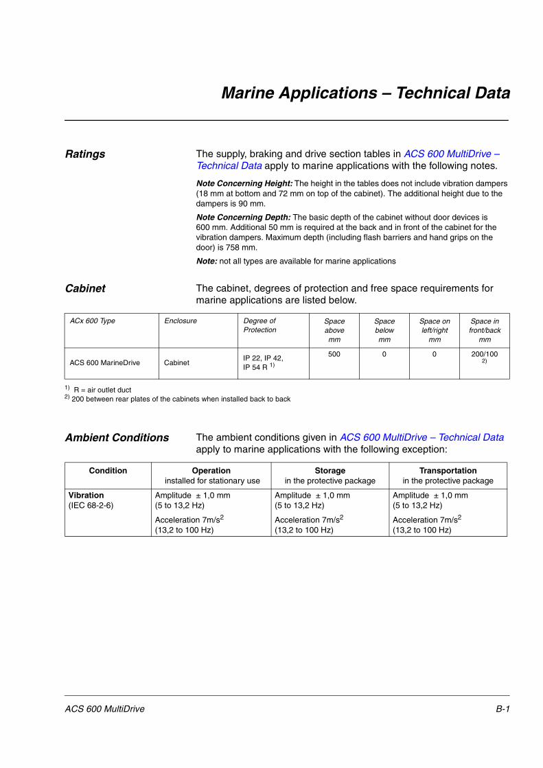
Marine Applications – Technical Data
Ratings The supply, braking and drive section tables in ACS 600 MultiDrive – Technical Data apply to marine applications with the following notes.
Note Concerning Height: The height in the tables does not include vibration dampers (18 mm at bottom and 72 mm on top of the cabinet). The additional height due to the dampers is 90 mm.
Note Concerning Depth: The basic depth of the cabinet without door devices is 600 mm. Additional 50 mm is required at the back and in front of the cabinet for the vibration dampers. Maximum depth (including flash barriers and hand grips on the door) is 758 mm.
Note: not all types are available for marine applications
Cabinet The cabinet, degrees of protection and free space requirements for marine applications are listed below.
1) R = air outlet duct2) 200 between rear plates of the cabinets when installed back to back
Ambient Conditions The ambient conditions given in ACS 600 MultiDrive – Technical Data apply to marine applications with the following exception:
ACx 600 Type Enclosure Degree of Protection
Spaceabove mm
Spacebelow mm
Space onleft/right
mm
Space infront/back
mm
ACS 600 MarineDrive CabinetIP 22, IP 42, IP 54 R 1)
500 0 0 200/1002)
Condition Operation installed for stationary use
Storagein the protective package
Transportationin the protective package
Vibration(IEC 68-2-6)
Amplitude ± 1,0 mm (5 to 13,2 Hz)
Acceleration 7m/s2 (13,2 to 100 Hz)
Amplitude ± 1,0 mm (5 to 13,2 Hz)
Acceleration 7m/s2 (13,2 to 100 Hz)
Amplitude ± 1,0 mm (5 to 13,2 Hz)
Acceleration 7m/s2 (13,2 to 100 Hz)
ACS 600 MultiDrive B-1

Marine Applications – Technical Data
Applicable Standards The ACS 600 MultiDrive for marine applications complies with the following standards:
• IEC 60092-302: 1997 Electrical installations in ships, low voltage switchgear and controlgear assemblies.
• EN 60204-1: 1992 + Corr. 1993 (IEC 204-1). Safety of machinery. Electrical equipment of machines. Part 1: General requirements.
• EN 60529: 1991 (IEC 529), IEC 664-1: 1992. Degrees of protection provided by enclosures (IP code).
• EN 50178: 1986. Electronic equipment for use in power installations.
• EN 61800-3 (1996): EMC product standard including specific test methods.
Materials
Other Technical Data See chapter ACS 600 MultiDrive – Technical Data. The data for ACS 600 MultiDrive applies also to marine applications if specific data is not included in this chapter.
Enclosure Coating Thickness
Colour
Hot-dip zinc coated steel sheet 1.0 to 2,5 mm with polyester thermosetting powder coating (only in visible parts)
60 �m RAL 7035 light beige semigloss
Flat BusbarsTin plated copperPackage
Wood or plywood (seaworthy package). Plastic covering of the package: PE-LD, bands PP or steel.
B-2 ACS 600 MultiDrive


ABB Industry OyDrivesP.O. Box 184FIN-00381 HELSINKIFINLANDTelephone +358 10 22 2000Telefax +358 10 22 22681Internet http://www.abb.com/automation
3AF
Y 6
3982
229
R01
25 R
EV
DE
FF
EC
TIV
E: 1
.12.
2000
EN
Related Documents