ACS 601/604/607 AC Drives US Supplement ACS 600 Hardware Manual Supplement

Welcome message from author
This document is posted to help you gain knowledge. Please leave a comment to let me know what you think about it! Share it to your friends and learn new things together.
Transcript
ACS 601/604/607 AC Drives US Supplement
ACS 600 Hardware Manual Supplement

2001 ABB Inc. All Rights Reserved.
ACS 601/604/607 US Supplement
Hardware Manual Supplement
ACS600-US-04S3AUA489002B5071 R0101 REV C
EFFECTIVE: 11/12/2001SUPERSEDES: 12/15/98

601/604/607 US Supplement i
Table of Contents
Safety Instructions. . . . . . . . . . . . . . . . . . . . . . . . . . . . . . . . . . . . . . . . . . . . . . . . . . . . . . . iii
Warnings and Notes . . . . . . . . . . . . . . . . . . . . . . . . . . . . . . . . . . . . . . . . . . . . . . . . . . . iiiWarnings . . . . . . . . . . . . . . . . . . . . . . . . . . . . . . . . . . . . . . . . . . . . . . . . . . . . . . . . . iiiNotes. . . . . . . . . . . . . . . . . . . . . . . . . . . . . . . . . . . . . . . . . . . . . . . . . . . . . . . . . . . . iii
Supply Connections. . . . . . . . . . . . . . . . . . . . . . . . . . . . . . . . . . . . . . . . . . . . . . . . . . . . vGround Fault Protective Function . . . . . . . . . . . . . . . . . . . . . . . . . . . . . . . . . . . . . . . . . viEmergency Stop Devices . . . . . . . . . . . . . . . . . . . . . . . . . . . . . . . . . . . . . . . . . . . . . . . viGround Connections . . . . . . . . . . . . . . . . . . . . . . . . . . . . . . . . . . . . . . . . . . . . . . . . . . . viMotor Connections. . . . . . . . . . . . . . . . . . . . . . . . . . . . . . . . . . . . . . . . . . . . . . . . . . . . viiConduit . . . . . . . . . . . . . . . . . . . . . . . . . . . . . . . . . . . . . . . . . . . . . . . . . . . . . . . . . . . . viiArmored Cable. . . . . . . . . . . . . . . . . . . . . . . . . . . . . . . . . . . . . . . . . . . . . . . . . . . . . . . vii
Motor Insulation Requirements . . . . . . . . . . . . . . . . . . . . . . . . . . . . . . . . . . . . . . . viiPower Factor Correction Capacitors . . . . . . . . . . . . . . . . . . . . . . . . . . . . . . . . . . . . ixOutput Contactors . . . . . . . . . . . . . . . . . . . . . . . . . . . . . . . . . . . . . . . . . . . . . . . . . . xEMC . . . . . . . . . . . . . . . . . . . . . . . . . . . . . . . . . . . . . . . . . . . . . . . . . . . . . . . . . . . . xMechanical Installation . . . . . . . . . . . . . . . . . . . . . . . . . . . . . . . . . . . . . . . . . . . . . . x
Chapter 1 – Introduction . . . . . . . . . . . . . . . . . . . . . . . . . . . . . . . . . . . . . . . . . . . . . . . . . 1-1
Overview . . . . . . . . . . . . . . . . . . . . . . . . . . . . . . . . . . . . . . . . . . . . . . . . . . . . . . . . . . 1-1Intended Audience. . . . . . . . . . . . . . . . . . . . . . . . . . . . . . . . . . . . . . . . . . . . . . . . . . . 1-1What this Manual Contains . . . . . . . . . . . . . . . . . . . . . . . . . . . . . . . . . . . . . . . . . . . . 1-1Related Publications . . . . . . . . . . . . . . . . . . . . . . . . . . . . . . . . . . . . . . . . . . . . . . . . . 1-2Product Family. . . . . . . . . . . . . . . . . . . . . . . . . . . . . . . . . . . . . . . . . . . . . . . . . . . . . . 1-2Delivery Check. . . . . . . . . . . . . . . . . . . . . . . . . . . . . . . . . . . . . . . . . . . . . . . . . . . . . . 1-2
Nameplate . . . . . . . . . . . . . . . . . . . . . . . . . . . . . . . . . . . . . . . . . . . . . . . . . . . . . . 1-2Type Code. . . . . . . . . . . . . . . . . . . . . . . . . . . . . . . . . . . . . . . . . . . . . . . . . . . . . . 1-2Frame Size . . . . . . . . . . . . . . . . . . . . . . . . . . . . . . . . . . . . . . . . . . . . . . . . . . . . . 1-2
ACx 600 Type Code . . . . . . . . . . . . . . . . . . . . . . . . . . . . . . . . . . . . . . . . . . . . . . . . . 1-3Inquiries . . . . . . . . . . . . . . . . . . . . . . . . . . . . . . . . . . . . . . . . . . . . . . . . . . . . . . . . . . . 1-4
Appendix A – ACS/ACC 600 Technical Data . . . . . . . . . . . . . . . . . . . . . . . . . . . . . . . . .A-1
Drive Output Ratings . . . . . . . . . . . . . . . . . . . . . . . . . . . . . . . . . . . . . . . . . . . . . . . . . A-1Output Current Derating For High Ambient Temperature . . . . . . . . . . . . . . . . . .A-3Diagram. . . . . . . . . . . . . . . . . . . . . . . . . . . . . . . . . . . . . . . . . . . . . . . . . . . . . . . . A-5Output Current Derating For High Altitude . . . . . . . . . . . . . . . . . . . . . . . . . . . . . A-6Temperature Derating For High Altitude . . . . . . . . . . . . . . . . . . . . . . . . . . . . . . . A-7
Fuses . . . . . . . . . . . . . . . . . . . . . . . . . . . . . . . . . . . . . . . . . . . . . . . . . . . . . . . . . . . . . A-8Cable Entries . . . . . . . . . . . . . . . . . . . . . . . . . . . . . . . . . . . . . . . . . . . . . . . . . . . . . . . A-9External Control Connections (NIOC) . . . . . . . . . . . . . . . . . . . . . . . . . . . . . . . . . . . A-11
Heat DIssipation Requirements. . . . . . . . . . . . . . . . . . . . . . . . . . . . . . . . . . . . . A-12
601/604/607 US Supplement ii
Cooling Air Flow Requirements . . . . . . . . . . . . . . . . . . . . . . . . . . . . . . . . . . . . . . . . A-13Dimensions and Weights . . . . . . . . . . . . . . . . . . . . . . . . . . . . . . . . . . . . . . . . . . . . A-14Input Power Connection . . . . . . . . . . . . . . . . . . . . . . . . . . . . . . . . . . . . . . . . . . . . . A-15Motor Connection . . . . . . . . . . . . . . . . . . . . . . . . . . . . . . . . . . . . . . . . . . . . . . . . . . A-15Efficiency and Cooling . . . . . . . . . . . . . . . . . . . . . . . . . . . . . . . . . . . . . . . . . . . . . . . A-15External Control Connections . . . . . . . . . . . . . . . . . . . . . . . . . . . . . . . . . . . . . . . . . A-16
Encoder Signals . . . . . . . . . . . . . . . . . . . . . . . . . . . . . . . . . . . . . . . . . . . . . . . . A-18Application Program . . . . . . . . . . . . . . . . . . . . . . . . . . . . . . . . . . . . . . . . . . . . . . . . A-19
Application Macros . . . . . . . . . . . . . . . . . . . . . . . . . . . . . . . . . . . . . . . . . . . . . . A-19Protection Features . . . . . . . . . . . . . . . . . . . . . . . . . . . . . . . . . . . . . . . . . . . . . . A-20
Equipment Warranty and Liability . . . . . . . . . . . . . . . . . . . . . . . . . . . . . . . . . . . . . . A-21Limitation of Liability . . . . . . . . . . . . . . . . . . . . . . . . . . . . . . . . . . . . . . . . . . . . . A-21
Appendix B – ACS/ACC 600 US Only Drawings . . . . . . . . . . . . . . . . . . . . . . . . . . . . . .B-1
601/604/607 US Supplement iii
Safety Instructions
Overview This chapter states the safety instructions which must be followedwhen installing, operating and servicing the ACx 600. If neglected,physical injury and death may follow, or damage may occur to the ACdrive, the motor and driven equipment. The material in this chaptermust be studied before attempting any work on, or with, the unit.
Warnings and Notes This manual distinguishes two sorts of safety instructions. Warningsare used to inform of conditions which can, if proper steps are nottaken, lead to a serious fault condition, physical injury or death. Notesare used when the reader is required to pay special attention or whenthere is additional information available on the subject. Notes are lesscrucial than Warnings, but should not be disregarded.
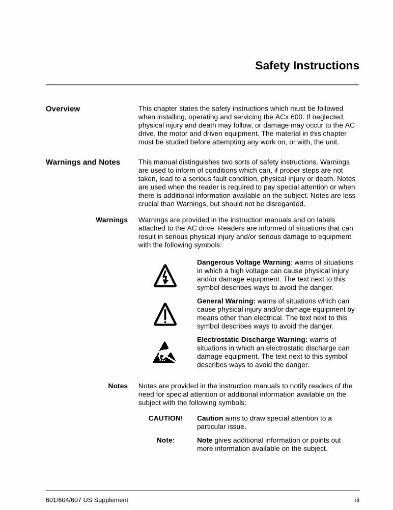
Warnings Warnings are provided in the instruction manuals and on labelsattached to the AC drive. Readers are informed of situations that canresult in serious physical injury and/or serious damage to equipmentwith the following symbols:
Notes Notes are provided in the instruction manuals to notify readers of theneed for special attention or additional information available on thesubject with the following symbols:
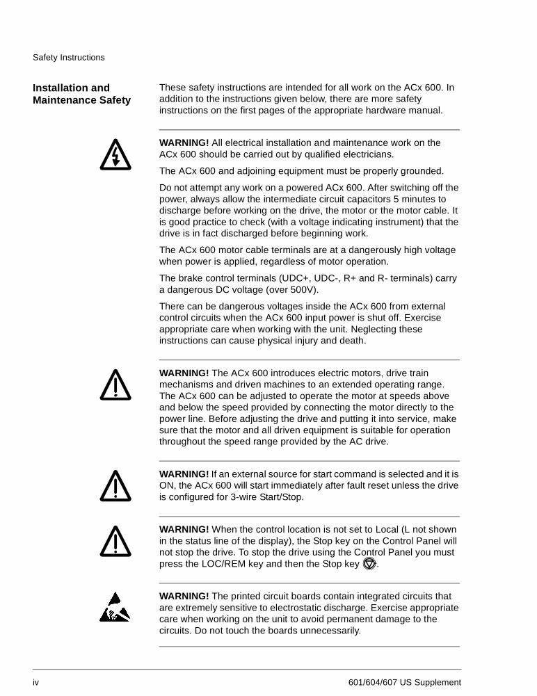
Dangerous Voltage Warning: warns of situationsin which a high voltage can cause physical injuryand/or damage equipment. The text next to thissymbol describes ways to avoid the danger.
General Warning: warns of situations which cancause physical injury and/or damage equipment bymeans other than electrical. The text next to thissymbol describes ways to avoid the danger.
Electrostatic Discharge Warning: warns ofsituations in which an electrostatic discharge candamage equipment. The text next to this symboldescribes ways to avoid the danger.
CAUTION! Caution aims to draw special attention to aparticular issue.
Note: Note gives additional information or points outmore information available on the subject.
Safety Instructions
iv 601/604/607 US Supplement
Installation andMaintenance Safety
These safety instructions are intended for all work on the ACx 600. Inaddition to the instructions given below, there are more safetyinstructions on the first pages of the appropriate hardware manual.
WARNING! All electrical installation and maintenance work on theACx 600 should be carried out by qualified electricians.
The ACx 600 and adjoining equipment must be properly grounded.
Do not attempt any work on a powered ACx 600. After switching off thepower, always allow the intermediate circuit capacitors 5 minutes todischarge before working on the drive, the motor or the motor cable. Itis good practice to check (with a voltage indicating instrument) that thedrive is in fact discharged before beginning work.
The ACx 600 motor cable terminals are at a dangerously high voltagewhen power is applied, regardless of motor operation.
The brake control terminals (UDC+, UDC-, R+ and R- terminals) carrya dangerous DC voltage (over 500V).
There can be dangerous voltages inside the ACx 600 from externalcontrol circuits when the ACx 600 input power is shut off. Exerciseappropriate care when working with the unit. Neglecting theseinstructions can cause physical injury and death.
WARNING! The ACx 600 introduces electric motors, drive trainmechanisms and driven machines to an extended operating range.The ACx 600 can be adjusted to operate the motor at speeds aboveand below the speed provided by connecting the motor directly to thepower line. Before adjusting the drive and putting it into service, makesure that the motor and all driven equipment is suitable for operationthroughout the speed range provided by the AC drive.
WARNING! If an external source for start command is selected and it isON, the ACx 600 will start immediately after fault reset unless the driveis configured for 3-wire Start/Stop.
WARNING! When the control location is not set to Local (L not shownin the status line of the display), the Stop key on the Control Panel willnot stop the drive. To stop the drive using the Control Panel you mustpress the LOC/REM key and then the Stop key .
WARNING! The printed circuit boards contain integrated circuits thatare extremely sensitive to electrostatic discharge. Exercise appropriatecare when working on the unit to avoid permanent damage to thecircuits. Do not touch the boards unnecessarily.
Safety Instructions
601/604/607 US Supplement v
WARNING! There are several automatic reset functions in the ACx600. If selected, they reset the unit and resume operation after a fault.These functions should not be selected if other equipment is notcompatible with this kind of operation, or dangerous situations can becaused by such action.
Supply Connections The ACx 601 does not include a disconnecting means. An input powerdisconnecting means must be installed between the AC power sourceand the ACx 601. The disconnecting means must conform to theapplicable safety regulations. The disconnecting means must belocked in the open position during installation and maintenance work.
The motor must not be controlled with the supply disconnecting means;instead, the and keys of the Control Panel or commands viathe I/O board of the ACx 600 should be used. The maximum number ofcharging cycles of the d.c. capacitors of ACx 600 (i.e. power-ups byapplying power) is five in ten minutes.
ACx 6x7 units include an on-load isolating fused disconnect with athrough the door handle. This switch does not switch off power fromthe EMC Line filter of the ACx 607-0490-3/5/6, -0610-3/5/6 and -0760-5/6 units. For ACx6x7-0490-3/5/6, -0610-3/5/6, and -0760-5/6 unitswith EMC filters and for the ACx 604 module, a supply disconnectingdevice must be installed in the supply, by which the electrical parts ofthe unit can be separated from the power network during installationand maintenance work. The supply disconnecting device must belocked to the open position during installation and maintenance work.
WARNING! Never connect the line power to the ACx 600 outputterminals U2, V2, or W2. If frequent bypassing is required, mechanicallyinterlocked switches or contactors should be employed. Line voltageapplied to the output may result in permanent damage to the unit.
Operation outside the nominal input line voltage range should not beattempted, as overvoltages can result in permanent damage to theACx 600.
If an ACx 601 with the integrated EMC filter (code 0 in the type code forEMC Filters) is connected to an ungrounded power system or highresistance grounded power system (over 30 Ohms), the power line willbe connected to ground potential through the EMC filter capacitors ofthe ACx 601. This may cause danger or damage the unit. Disconnectthe EMC filter capacitors before connecting the ACx 601 to anungrounded power system. For detailed instructions on how to do this,please contact your local ABB distributor.
It is not allowed to install an ACx6x4/6x7 with EMC filter options to
Safety Instructions
vi 601/604/607 US Supplement
ungrounded systems, or high resistance grounded power systems(over 30 ohms). The main power will be connected to earth potentialthrough the EMC filter of the ACx 600 which may cause danger ordamage to the unit. Disconnect the EMC filter capacitors beforeconnecting the ACx 600 to ungrounded systems. For detailedinstructions on how to do this, please contact your local ABBdistributor.
Ground FaultProtective Function
The ACx 600 is equipped with an internal ground fault protectivefunction to protect the unit against ground faults in the drive, the motorand the motor cable. This is not a personal safety or a fire protectionfeature. The ground fault protective function of the ACx 600 can be setto warning only by Parameter 30.17 for Standard Application Programand Parameter 30.11 for Crane Application Program. The internalground (earth) fault protection is not in use in the 12-pulse suppliedunits. For ACX 62x units, refer to the ACx 607 hardware manualsubsection labelled “Special ACx 6x7 units from 315 to 630 kW”.
The EMC filter of the ACx 600 includes capacitors connected betweenthe power circuit and the chassis. These capacitors increase theground leakage current from the AC line through the ground (PE)connection and may cause some ground fault current circuit breakersto trip.
Emergency StopDevices
The person responsible for the overall design and operation of thedriven process must make sure that the installation includesemergency stop devices and any other safety equipment that may beneeded. Pressing the STOP key on the Control Panel of ACx 600 doesnot generate an emergency stop of the motor or separate the drivefrom dangerous potential. A Line Contactor with provisions for aremote power cut-off switch is available as a factory installed option forthe ACx 607. Cutting off power to the drive allows the motor to coast toa stop.
Ground Connections The ACx 600 and adjoining equipment must be properly grounded.
The ACx 600 and the motor must be grounded at the installation site toensure personnel safety in all circumstances and in addition to reduceelectromagnetic emission and pick-up. Make sure that groundingconductors are adequately sized as required by safety regulations.
In CE compliant installations and in other installations where EMCemissions must be minimized, 360 degree high frequency grounding ofcable entries is done in order to suppress electromagneticdisturbances. In addition, power cable shields must be connected tothe ground (PE) in order to meet safety regulations. Power cableshields are suitable for use as equipment grounding conductors onlywhen the shield conductors are adequately sized as required by safetyregulations.
Safety Instructions
601/604/607 US Supplement vii
The ACx 600 ground terminals should not be connected in series incase of a multiple installation. Incorrect grounding can cause physicalinjury, death or equipment malfunction and increase electromagneticinterference.
Motor Connections
WARNING! Operation is not allowed if the motor nominal voltage isless than one half of the ACx 600 nominal input voltage, or the motornominal current is less than 1/6 of the ACx 600 nominal output current.
WARNING! Do not make any voltage tolerance or insulation resistancetest (Hi-Pot or Megger) on any part of the ACx 600. Disconnect motorwires before making any tests of the motor or the cables between thedrive and motor.
Conduit Metallic conduit must be used for motor wiring unless armored cable orpower shield cable is used. Where conduits must be coupled together,the joint must be bridged with a ground conductor bonded to theconduit on each side of the joint. The conduits must also be bonded tothe drive enclosure. Use separate conduits for input power, motor,brake resistors, and control wiring. Do not run motor wiring from morethan one drive in the same conduit.
Armored Cable If metallic conduit is not used, type MC continuous corrugatedaluminum armor cable with symmetrical grounds or power shield cablemust be used for the motor cables. If these cables are used, the motorcables can be run in the same cable tray as other 460V or 600V powerwiring. Control and signal cables must not be run in the same tray aspower cables.
Six conductor (3 phases and 3 ground) type MC continuous corrugatedaluminum armor cable with symmetrical grounds is available from thefollowing suppliers. Trade names are in parentheses.
Anixter Wire & Cable (Philsheath)
BICC General Corp (Philsheath)
Rockbestos Co. (Gardex)
Oaknite (CLX)
Power shielded cables are available from Belded, Olflex, and Pirelli.
Motor InsulationRequirements
As with all AC drives employing the most modern IGBT invertortechnology, the output waveform of the ACx 600 consists of a series ofrectangular voltage pulses. Regardless of the output frequency, thevoltage of the pulses is approximately 1.35 times the input line voltagewith a very short rise time.
Safety Instructions
viii 601/604/607 US Supplement
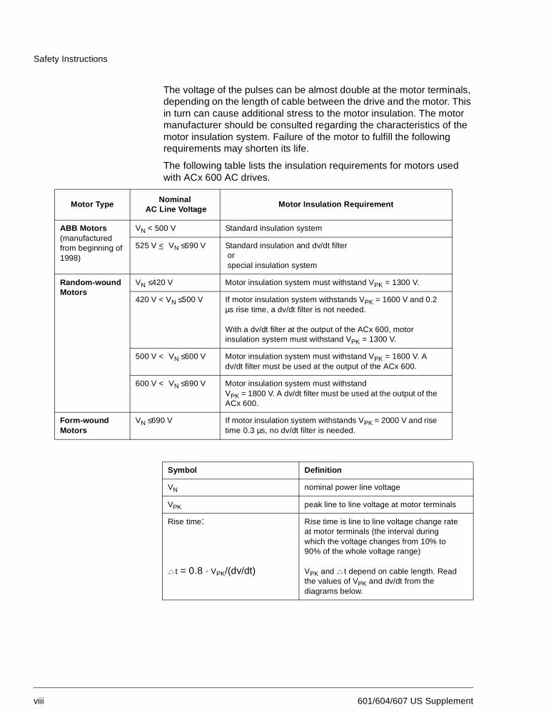
The voltage of the pulses can be almost double at the motor terminals,depending on the length of cable between the drive and the motor. Thisin turn can cause additional stress to the motor insulation. The motormanufacturer should be consulted regarding the characteristics of themotor insulation system. Failure of the motor to fulfill the followingrequirements may shorten its life.
The following table lists the insulation requirements for motors usedwith ACx 600 AC drives.
Motor TypeNominal
AC Line VoltageMotor Insulation Requirement
ABB Motors(manufacturedfrom beginning of1998)
VN < 500 V Standard insulation system
525 V < VN ≤690 V Standard insulation and dv/dt filterorspecial insulation system
Random-woundMotors
VN ≤420 V Motor insulation system must withstand VPK = 1300 V.
420 V < VN ≤500 V If motor insulation system withstands VPK = 1600 V and 0.2µs rise time, a dv/dt filter is not needed.
With a dv/dt filter at the output of the ACx 600, motorinsulation system must withstand VPK = 1300 V.
500 V < VN ≤600 V Motor insulation system must withstand VPK = 1600 V. Adv/dt filter must be used at the output of the ACx 600.
600 V < VN ≤690 V Motor insulation system must withstandVPK = 1800 V. A dv/dt filter must be used at the output of theACx 600.
Form-woundMotors
VN ≤690 V If motor insulation system withstands VPK = 2000 V and risetime 0.3 µs, no dv/dt filter is needed.
Symbol Definition
VN nominal power line voltage
VPK peak line to line voltage at motor terminals
Rise time:
t = 0.8 · VPK/(dv/dt)
Rise time is line to line voltage change rateat motor terminals (the interval duringwhich the voltage changes from 10% to90% of the whole voltage range)
VPK and t depend on cable length. Readthe values of VPK and dv/dt from thediagrams below.
Safety Instructions
601/604/607 US Supplement ix
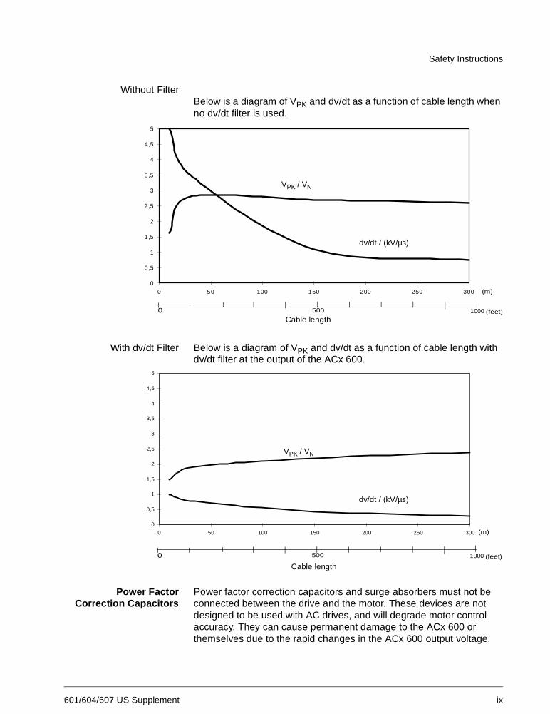
Without FilterBelow is a diagram of VPK and dv/dt as a function of cable length whenno dv/dt filter is used.
With dv/dt Filter Below is a diagram of VPK and dv/dt as a function of cable length withdv/dt filter at the output of the ACx 600.
Power FactorCorrection Capacitors
Power factor correction capacitors and surge absorbers must not beconnected between the drive and the motor. These devices are notdesigned to be used with AC drives, and will degrade motor controlaccuracy. They can cause permanent damage to the ACx 600 orthemselves due to the rapid changes in the ACx 600 output voltage.
0
0,5
1
1,5
2
2,5
3
3,5
4
4,5
5
0 50 100 150 200 250 300
dv/dt / (kV/µs)
VPK / VN
Cable length0 1000500
(m)
(feet)
0
0,5
1
1,5
2
2,5
3
3,5
4
4,5
5
0 50 100 150 200 250 300
dv/dt / (kV/µs)
VPK / VN
0 1000500 (feet)
(m)
Cable length
Safety Instructions
x 601/604/607 US Supplement
Power factor correction capacitors in parallel with the ACx 600 threephase input can be problematic. Contact factory if questions arise.
Output Contactors If a contactor is used between the output of the ACx 600 and the motorwith DTC control mode selected, the output voltage of the ACx 600must be controlled to zero before the contactor is opened: ACx 600units via parameter 21.3, choose COAST. If RAMP is selected, theoutput of the ACx 600 must be reduced to zero using Parameter 16.1by giving zero V DC to the selected digital input. Otherwise thecontactor will be damaged. In scalar control the contactor can beopened with ACx/ACC 600 running.
Varistors or RC networks (AC) or diodes (DC) should be used toprotect against voltage transients generated by contactor coils. Theprotective components should be mounted as close as possible to thecontactor coils. Protective components should not be installed at theNIOC board terminal block.
EMC When used with inductive loads (relays, contactors, motors), the relaycontacts of ACx 600 must be protected with varistors or RC networks(AC) or diodes (DC) against voltage transients. The protectivecomponents should not be installed at the NIOC board terminal block.
Installing control devices (contactors or relays) or control cables otherthan those of the ACx 600 inside the drive enclosure is not acceptable.
Note: If safety switches, contactors, connection boxes or similarequipment are installed between the drive and the motor, they shouldbe installed in a metal enclosure in a way that the conduit or motorcable shielding runs consistently without breaks from the drive to themotor, so the emission level will be minimized.
Mechanical Installation CAUTION! The ACx 601 weighs a considerable amount, and shouldnot be handled by the front cover. The unit should only be placed on itsback. Exercise appropriate care when maneuvering the unit to avoiddamage and injury. Lifting the ACx 601 is much easier and safer withtwo people working together.
CAUTION! The ACx 6x7 should only be transported on the originalpallet, or with a proper lifting device using the lifting lugs on top of thecabinet. The drive is not intended to be lifted by running lines underthe unit. The ACx 607 center of gravity is quite high, and there is a riskof over turning the unit. The ACx 607 can be laid on it’s back to fitthough confined spaces. Exercise appropriate care whenmaneuvering the unit to avoid damage or injury.
CAUTION! Make sure that dust from drilling does not enter theACx 600 when installing. Electrically conductive dust inside the unitmay cause damage or lead to malfunction.
Safety Instructions
601/604/607 US Supplement xi
CAUTION! Do not fasten the ACx 600 by riveting or welding.
WARNING! The cooling air flows and space requirements must befulfilled. Special attention must be paid to cooling if units are installed inconfined spaces and user defined cabinets.
Safety Instructions
xii 601/604/607 US Supplement
601/604/607 US Supplement 1-1
Chapter 1 – Introduction
Overview This chapter describes the purpose and contents of this manual.
This manual is a supplement to the ACx 601/604/607 AC Drive Hardware Manuals. The information contained in this manual is:
• specific to 200 to 240 VAC product as well as 380-500 V productdistinguished by digit 11 in the ACS 600 type code being designatedas a 4. The information in the manual takes precedent over anycontradictory data found in any other user manual.
• for installations within the United States that must be installed perthe National Electric Code and local codes.
Intended Audience The intended audience of this manual are people who are responsiblefor installing, starting and servicing the ACx 601 or ACx 604/607 ACdrive. The audience is expected to:
• Have a basic knowledge of physical and electrical fundamentals,electrical wiring practices, electrical components and electricalschematic symbols.
• Have no prior experience of ABB products.
• Have no prior experience of AC drives.
• Have no prior experience of the ACx 600 product family.
• Have no prior experience or training of installing, commissioning,operating and servicing the ACx 600.
What this ManualContains
Safety Instructions are placed on the first pages of this manual. Thesafety instructions describe the formats for various warnings andnotations in use in this manual. The chapter also states the generalsafety instructions that are intended for all work on the ACx 600.
Chapter 1 - Introduction gives information on the related publications,product family, delivery check, and type code of the ACx 601 or ACx604/607. Chapter 1 in this manual supersedes the entire Chapter 1 inthe ACx 601 and ACx 604/607 AC Drive Hardware Manuals.
Appendix A - ACx 604/607 Technical Data lists the ACx 600 technicalspecifications. Appendix A in this manual supersedes the entireAppendix A in the ACx 601 and ACx 604/607 AC Drive HardwareManuals. Refer only to the Appendix A in this manual and disregard theAppendix A in the Hardware Manuals.
Chapter 1 – Introduction
1-2 601/604/607 US Supplement
Related Publications In addition to this manual the ACx 601/604/607 AC drive userdocumentation includes the following publications:
• ACx 601 or ACx 604/607 Hardware Manual
• ACx 600 Firmware Manual
• ACx 600 DriveWindow User’s Manual (optional)
• Several Option Module Manuals
• ACx 600 Technical Catalog
• ACx 600 Converter Module Installation In User Defined Cabinet
Product Family The ACx 600 product family of three phase AC drives includes
• the ACx 600 (for most applications)
• the ACC 600 (for crane drive applications)
• the ACx 600 MultiDrive (for multi drive applications)
The application programs are introduced in Appendix – A.
Study this manual carefully before installing, commissioning, operatingor servicing the drive. We expect that you have a basic knowledge ofphysical and electrical fundamentals, electrical wiring practices,electrical components and electrical schematic symbols.
Delivery Check Check that there are no signs of damage. Before attempting installationand operation, check the information on the drive nameplate to verifythat the unit is the correct model.
Nameplate Each ACx 600 has a nameplate for identification purposes. See Figure1-1. The nameplate data includes a type code and a serial numberwhich allow individual recognition of each unit.
Type Code The ACx 600 Type Code contains information on the properties andconfiguration of the drive. The Type Code Chart explains thesignificance of each digit or character in the Type Code.
Frame Size ACx 600 drives are manufactured in several different chassis sizes thatare designated as Frame R2, R3, etc. Drives of several different ratingsare manufactured in the same frame. The ACx 600 rating tables onpage A-1 in Appendix A list the Frame Size used for each Type Code.The Frame Size is not marked on the nameplate.
Chapter 1 – Introduction
601/604/607 US Supplement 1-3
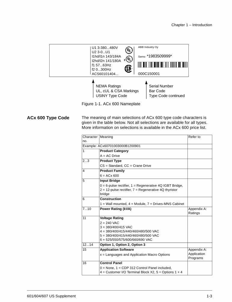
Figure 1-1. ACx 600 Nameplate
ACx 600 Type Code The meaning of main selections of ACx 600 type code characters isgiven in the table below. Not all selections are available for all types.More information on selections is available in the ACx 600 price list.
Characterno.
Meaning Refer to
Example: ACx60701003000B1200901
1 Product CategoryA = AC Drive
2...3 Product TypeCS = Standard, CC = Crane Drive
4 Product Family6 = ACx 600
5 Input Bridge0 = 6-pulse rectifier, 1 = Regenerative 4Q IGBT Bridge,2 = 12-pulse rectifier, 7 = Regenerative 4Q thyristorbridge
6 Construction1 = Wall mounted, 4 = Module, 7 = Drives-MNS Cabinet
7...10 Power Rating (kVA) Appendix A:Ratings
11 Voltage Rating2 = 240 VAC3 = 380/400/415 VAC4 = 380/400/415/440/460/480/500 VAC5 = 380/400/415/440/460/480/500 VAC6 = 525/550/575/600/660/690 VAC
12...14 Option 1, Option 2, Option 315 Application Software Appendix A:
ApplicationPrograms
x = Languages and Application Macro Options
16 Control Panel0 = None, 1 = CDP 312 Control Panel included,4 = Customer I/O Terminal Block X2, 5 = Options 1 + 4
U1 3-380...500VU2 3-0...U1I1n/I1nsq 168/198AI2n/I2nsq 164/193Af1 48...63Hzf2 0...300HzACS60101405...
U1 3-380...480VU2 3-0...U1I1hd/I1n 143/184AI2hd/I2n 141/180Af1 57...63Hzf2 0...300HzACS60101404...
ABB Industry Oy
Serno *1983509999*
000C150001
IEC RatingsCE MarkingFIIND Type Code
NEMA RatingsUL, cUL & CSA MarkingsUSINY Type Code
Serial NumberBar CodeType Code continued
Chapter 1 – Introduction
1-4 601/604/607 US Supplement
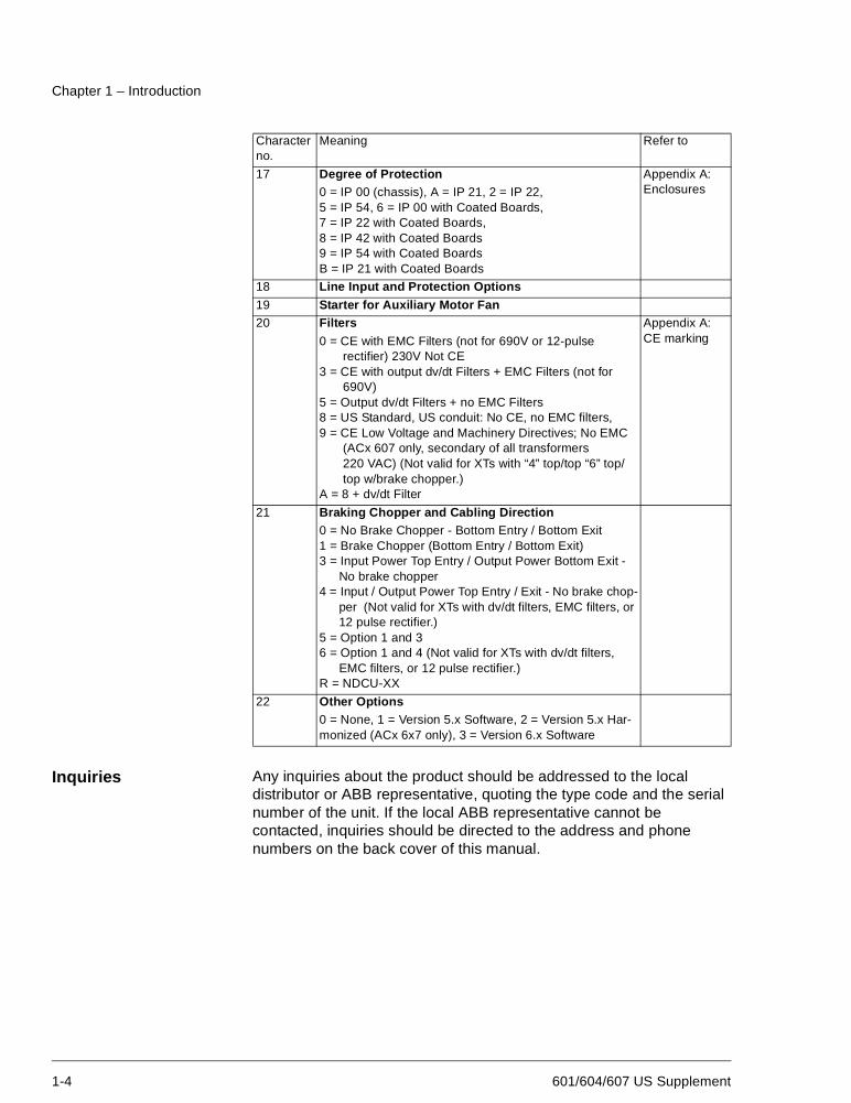
Inquiries Any inquiries about the product should be addressed to the localdistributor or ABB representative, quoting the type code and the serialnumber of the unit. If the local ABB representative cannot becontacted, inquiries should be directed to the address and phonenumbers on the back cover of this manual.
17 Degree of Protection Appendix A:Enclosures0 = IP 00 (chassis), A = IP 21, 2 = IP 22,
5 = IP 54, 6 = IP 00 with Coated Boards,7 = IP 22 with Coated Boards,8 = IP 42 with Coated Boards9 = IP 54 with Coated BoardsB = IP 21 with Coated Boards
18 Line Input and Protection Options19 Starter for Auxiliary Motor Fan20 Filters Appendix A:
CE marking0 = CE with EMC Filters (not for 690V or 12-pulserectifier) 230V Not CE
3 = CE with output dv/dt Filters + EMC Filters (not for690V)
5 = Output dv/dt Filters + no EMC Filters8 = US Standard, US conduit: No CE, no EMC filters,9 = CE Low Voltage and Machinery Directives; No EMC
(ACx 607 only, secondary of all transformers220 VAC) (Not valid for XTs with “4” top/top “6” top/top w/brake chopper.)
A = 8 + dv/dt Filter
21 Braking Chopper and Cabling Direction0 = No Brake Chopper - Bottom Entry / Bottom Exit1 = Brake Chopper (Bottom Entry / Bottom Exit)3 = Input Power Top Entry / Output Power Bottom Exit -
No brake chopper4 = Input / Output Power Top Entry / Exit - No brake chop-
per (Not valid for XTs with dv/dt filters, EMC filters, or12 pulse rectifier.)
5 = Option 1 and 36 = Option 1 and 4 (Not valid for XTs with dv/dt filters,
EMC filters, or 12 pulse rectifier.)R = NDCU-XX
22 Other Options0 = None, 1 = Version 5.x Software, 2 = Version 5.x Har-monized (ACx 6x7 only), 3 = Version 6.x Software
Characterno.
Meaning Refer to
601/604/607 US Supplement A-1
Appendix A – ACS/ACC 600 Technical Data
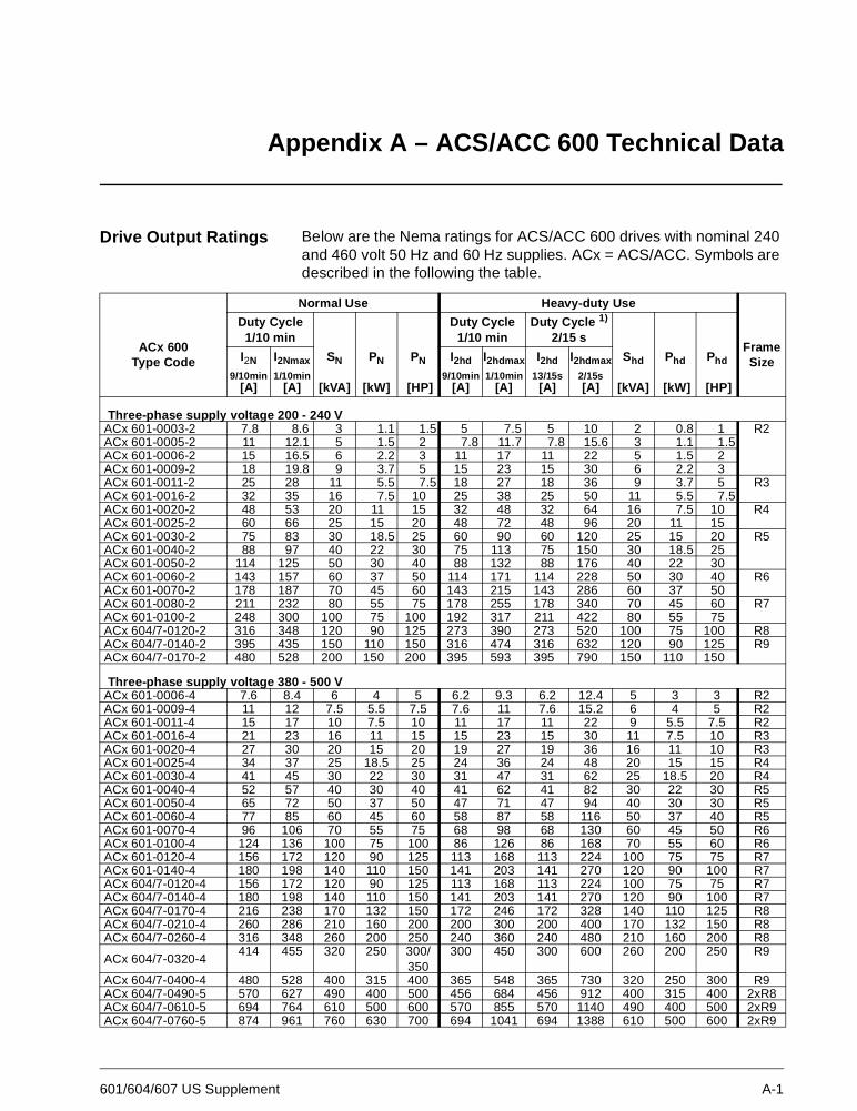
Drive Output Ratings Below are the Nema ratings for ACS/ACC 600 drives with nominal 240and 460 volt 50 Hz and 60 Hz supplies. ACx = ACS/ACC. Symbols aredescribed in the following the table.
Normal Use Heavy-duty Use
ACx 600Type Code
Duty Cycle1/10 min
Duty Cycle1/10 min
Duty Cycle 1)
2/15 sFrameSizeI2N
9/10min[A]
I2Nmax
1/10min[A]
SN
[kVA]
PN
[kW]
PN
[HP]
I2hd
9/10min[A]
I2hdmax
1/10min[A]
I2hd
13/15s[A]
I2hdmax
2/15s[A]
Shd
[kVA]
Phd
[kW]
Phd
[HP]
Three-phase supply voltage 200 - 240 VACx 601-0003-2 7.8 8.6 3 1.1 1.5 5 7.5 5 10 2 0.8 1 R2ACx 601-0005-2 11 12.1 5 1.5 2 7.8 11.7 7.8 15.6 3 1.1 1.5ACx 601-0006-2 15 16.5 6 2.2 3 11 17 11 22 5 1.5 2ACx 601-0009-2 18 19.8 9 3.7 5 15 23 15 30 6 2.2 3ACx 601-0011-2 25 28 11 5.5 7.5 18 27 18 36 9 3.7 5 R3ACx 601-0016-2 32 35 16 7.5 10 25 38 25 50 11 5.5 7.5ACx 601-0020-2 48 53 20 11 15 32 48 32 64 16 7.5 10 R4ACx 601-0025-2 60 66 25 15 20 48 72 48 96 20 11 15ACx 601-0030-2 75 83 30 18.5 25 60 90 60 120 25 15 20 R5ACx 601-0040-2 88 97 40 22 30 75 113 75 150 30 18.5 25ACx 601-0050-2 114 125 50 30 40 88 132 88 176 40 22 30ACx 601-0060-2 143 157 60 37 50 114 171 114 228 50 30 40 R6ACx 601-0070-2 178 187 70 45 60 143 215 143 286 60 37 50ACx 601-0080-2 211 232 80 55 75 178 255 178 340 70 45 60 R7ACx 601-0100-2 248 300 100 75 100 192 317 211 422 80 55 75ACx 604/7-0120-2 316 348 120 90 125 273 390 273 520 100 75 100 R8ACx 604/7-0140-2 395 435 150 110 150 316 474 316 632 120 90 125 R9ACx 604/7-0170-2 480 528 200 150 200 395 593 395 790 150 110 150
Three-phase supply voltage 380 - 500 VACx 601-0006-4 7.6 8.4 6 4 5 6.2 9.3 6.2 12.4 5 3 3 R2ACx 601-0009-4 11 12 7.5 5.5 7.5 7.6 11 7.6 15.2 6 4 5 R2ACx 601-0011-4 15 17 10 7.5 10 11 17 11 22 9 5.5 7.5 R2ACx 601-0016-4 21 23 16 11 15 15 23 15 30 11 7.5 10 R3ACx 601-0020-4 27 30 20 15 20 19 27 19 36 16 11 10 R3ACx 601-0025-4 34 37 25 18.5 25 24 36 24 48 20 15 15 R4ACx 601-0030-4 41 45 30 22 30 31 47 31 62 25 18.5 20 R4ACx 601-0040-4 52 57 40 30 40 41 62 41 82 30 22 30 R5ACx 601-0050-4 65 72 50 37 50 47 71 47 94 40 30 30 R5ACx 601-0060-4 77 85 60 45 60 58 87 58 116 50 37 40 R5ACx 601-0070-4 96 106 70 55 75 68 98 68 130 60 45 50 R6ACx 601-0100-4 124 136 100 75 100 86 126 86 168 70 55 60 R6ACx 601-0120-4 156 172 120 90 125 113 168 113 224 100 75 75 R7ACx 601-0140-4 180 198 140 110 150 141 203 141 270 120 90 100 R7ACx 604/7-0120-4 156 172 120 90 125 113 168 113 224 100 75 75 R7ACx 604/7-0140-4 180 198 140 110 150 141 203 141 270 120 90 100 R7ACx 604/7-0170-4 216 238 170 132 150 172 246 172 328 140 110 125 R8ACx 604/7-0210-4 260 286 210 160 200 200 300 200 400 170 132 150 R8ACx 604/7-0260-4 316 348 260 200 250 240 360 240 480 210 160 200 R8
ACx 604/7-0320-4414 455 320 250 300/
350300 450 300 600 260 200 250 R9
ACx 604/7-0400-4 480 528 400 315 400 365 548 365 730 320 250 300 R9ACx 604/7-0490-5 570 627 490 400 500 456 684 456 912 400 315 400 2xR8ACx 604/7-0610-5 694 764 610 500 600 570 855 570 1140 490 400 500 2xR9ACx 604/7-0760-5 874 961 760 630 700 694 1041 694 1388 610 500 600 2xR9
Appendix A – ACS/ACC 600 Technical Data
A-2 601/604/607 US Supplement
Current ratings are for operation up to 1000m (3300 ft)altitude and 40°C(104°F) ambient temperature (35°C/95°Ffor models ACx 601-0025-2, ACx 601-0050-2 and ACx 601-0070-2 in IP54 enclosures). For high temperature andaltitude derating, see pages A-3 to A-7.
The current ratings are the same regardless of the supplyvoltage within one voltage range. The rated current of theACx 60x must be higher than or equal to the rated motorcurrent to achieve the rated motor power given in the table.
Note 1: The maximum allowed motor shaft power is limitedto 1.5 · Phd. If the limit is exceeded, the motor torque andthe Ihdmax 2 s current is automatically restricted. Thefunction protects the input bridge of the ACx 600 againstoverload.
Note 2: The load capacity (current and power) decreases ifthe installation site altitude exceeds 1000 meters (3300 ft.),or if the ambient temperature exceeds 40 °C.
Usually dv/dt filters are not needed at the output of 240 Vunits.
Appendix A – ACS/ACC 600 Technical Data
601/604/607 US Supplement A-3
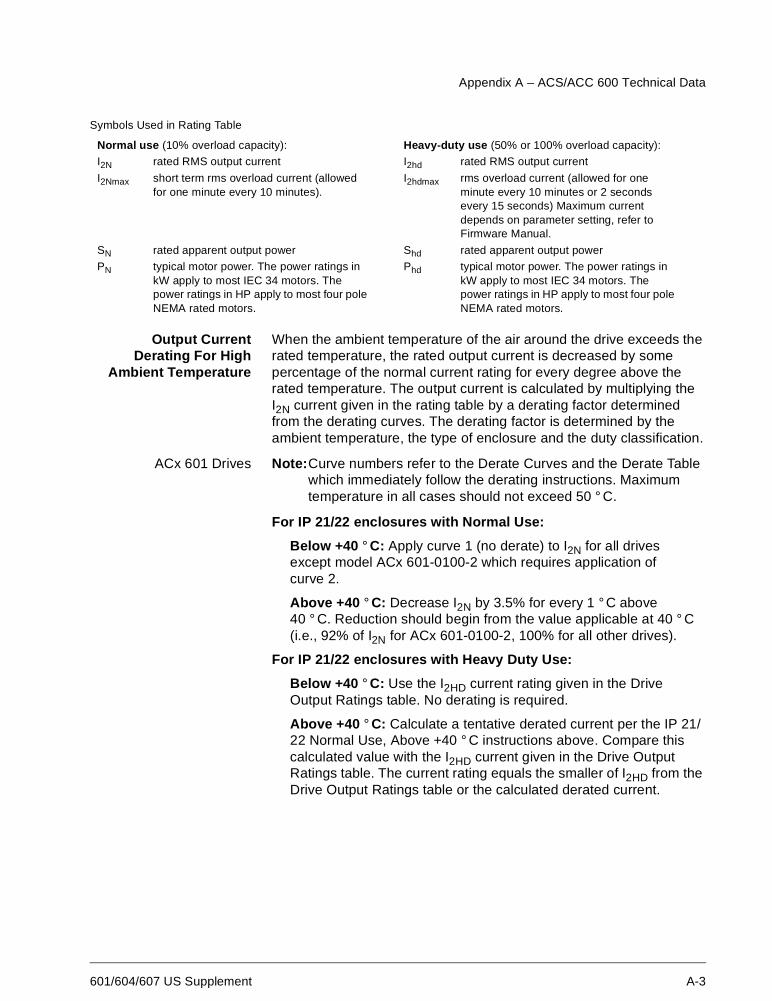
Symbols Used in Rating Table
Output CurrentDerating For High
Ambient Temperature
When the ambient temperature of the air around the drive exceeds therated temperature, the rated output current is decreased by somepercentage of the normal current rating for every degree above therated temperature. The output current is calculated by multiplying theI2N current given in the rating table by a derating factor determinedfrom the derating curves. The derating factor is determined by theambient temperature, the type of enclosure and the duty classification.
ACx 601 Drives Note:Curve numbers refer to the Derate Curves and the Derate Tablewhich immediately follow the derating instructions. Maximumtemperature in all cases should not exceed 50 ° C.
For IP 21/22 enclosures with Normal Use:
Below +40 ° C: Apply curve 1 (no derate) to I2N for all drivesexcept model ACx 601-0100-2 which requires application ofcurve 2.
Above +40 ° C: Decrease I2N by 3.5% for every 1 °C above40 ° C. Reduction should begin from the value applicable at 40 ° C(i.e., 92% of I2N for ACx 601-0100-2, 100% for all other drives).
For IP 21/22 enclosures with Heavy Duty Use:
Below +40 ° C: Use the I2HD current rating given in the DriveOutput Ratings table. No derating is required.
Above +40 ° C: Calculate a tentative derated current per the IP 21/22 Normal Use, Above +40 ° C instructions above. Compare thiscalculated value with the I2HD current given in the Drive OutputRatings table. The current rating equals the smaller of I2HD from theDrive Output Ratings table or the calculated derated current.
Normal use (10% overload capacity): Heavy-duty use (50% or 100% overload capacity):
I2N rated RMS output current I2hd rated RMS output current
I2Nmax short term rms overload current (allowedfor one minute every 10 minutes).
I2hdmax rms overload current (allowed for oneminute every 10 minutes or 2 secondsevery 15 seconds) Maximum currentdepends on parameter setting, refer toFirmware Manual.
SN rated apparent output power Shd rated apparent output power
PN typical motor power. The power ratings inkW apply to most IEC 34 motors. Thepower ratings in HP apply to most four poleNEMA rated motors.
Phd typical motor power. The power ratings inkW apply to most IEC 34 motors. Thepower ratings in HP apply to most four poleNEMA rated motors.
Appendix A – ACS/ACC 600 Technical Data
A-4 601/604/607 US Supplement
For IP 54 enclosures with Normal Use:
Below +40 °C: Locate the pertinent drive type code in the DerateTable to determine the curve number to apply. Find the ambienttemperature at the bottom of the Derate Curves. Follow thistemperature up vertically to where it meets the applicable curvenumber. From the point of intersection read across horizontally todetermine the appropriate percent derate. The current rating equalsthe I2N current from the Drive Output Ratings table times the percentderate.
Above +40 ° C: Calculate the I2N current derate (if any) at 40 ° Cper the IP 54 Normal Use, Below +40 ° C instructions immediatelyabove. Starting from this current level decrease the current rating anadditional 3.5% of I2N for each 1 °C above 40 ° C.
For IP 54 enclosures with Heavy Duty Use:
Below +40 °C: Use the I2HD current rating given in the DriveOutput Ratings table. No derating is required.
Above +40 ° C: Calculate a tentative derated current per the IP 54Normal Use, Above +40 °C instructions above. Compare thiscalculated value with the I2HD current given in the Drive OutputRatings table. The current rating equals the smaller of I2HD from theDrive Output Ratings table or the calculated derated current.
ACx 607 Drives Maximum temperature in all cases should not exceed 50 ° C.
For IP 21/22 enclosures with Normal Use:
Below +40 °C: Use the I2N current rating given in the Drive OutputRatings table. No derating is required.
Above +40 ° C: Decrease I2N by 1.5% for every 1 ° C above40 ° C.
For IP 21/22 enclosures with Heavy Duty Use:
Below +40 °C: Use the I2HD current rating given in the DriveOutput Ratings table. No derating is required.
Above +40 ° C: Use the I2HD current rating given in the DriveOutput Ratings table. No derating is required.
For IP 54 enclosures with Normal Use:
Below +40 °C: Use the I2N current rating given in the Drive OutputRatings table. No derating is required.
Above +40 ° C: Decrease I2N by 1.5% for every 1 ° C above40 ° C.
For IP 54 enclosures with Heavy Duty Use:
Below +40 °C: Use the I2HD current rating given in the DriveOutput Ratings table. No derating is required.
Above +40 ° C: Use the I2HD current rating given in the Drive
Appendix A – ACS/ACC 600 Technical Data
601/604/607 US Supplement A-5
Output Ratings table. No derating is required.
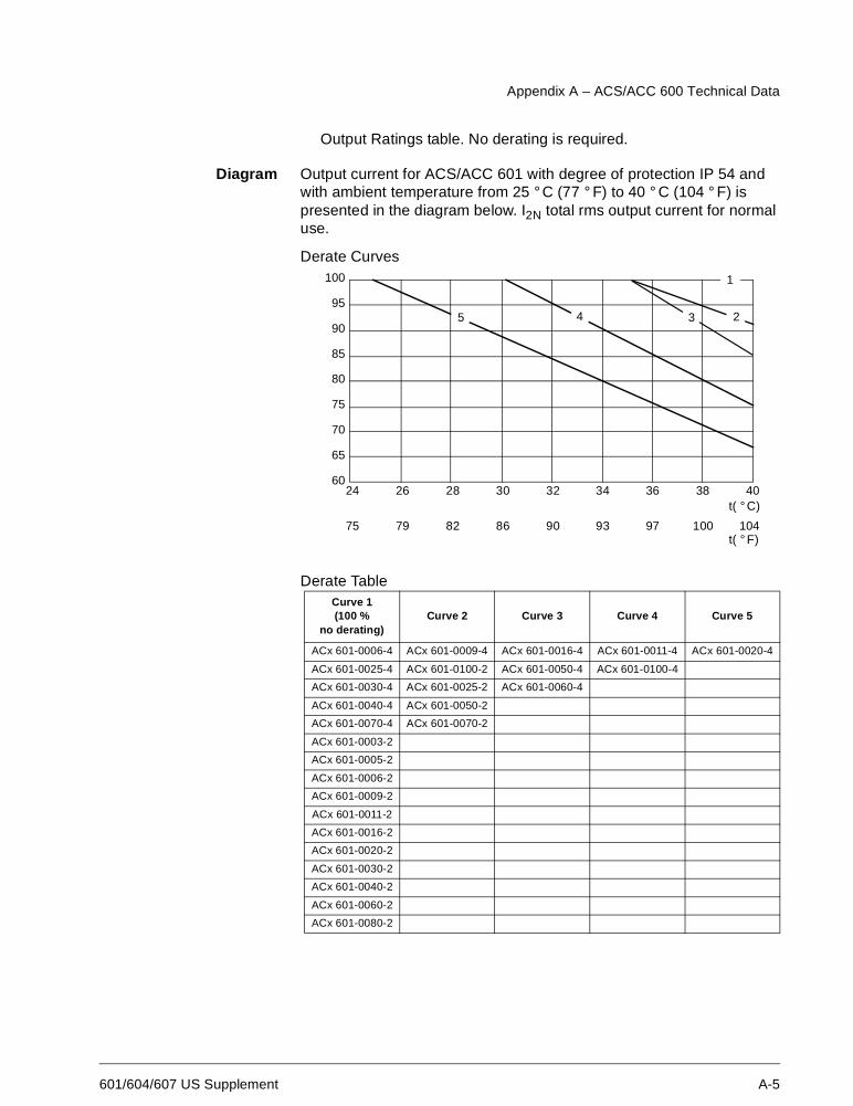
Diagram Output current for ACS/ACC 601 with degree of protection IP 54 andwith ambient temperature from 25 °C (77 ° F) to 40 ° C (104 ° F) ispresented in the diagram below. I2N total rms output current for normaluse.
Derate Curves
Derate TableCurve 1(100 %
no derating)Curve 2 Curve 3 Curve 4 Curve 5
ACx 601-0006-4 ACx 601-0009-4 ACx 601-0016-4 ACx 601-0011-4 ACx 601-0020-4
ACx 601-0025-4 ACx 601-0100-2 ACx 601-0050-4 ACx 601-0100-4
ACx 601-0030-4 ACx 601-0025-2 ACx 601-0060-4
ACx 601-0040-4 ACx 601-0050-2
ACx 601-0070-4 ACx 601-0070-2
ACx 601-0003-2
ACx 601-0005-2
ACx 601-0006-2
ACx 601-0009-2
ACx 601-0011-2
ACx 601-0016-2
ACx 601-0020-2
ACx 601-0030-2
ACx 601-0040-2
ACx 601-0060-2
ACx 601-0080-2
100
95
90
85
80
75
70
65
6024 26 28 30 32 34 36 38 40
75 79 82 86 90 93 97 100
1
2345
104
t( ° C)
t( ° F)
Appendix A – ACS/ACC 600 Technical Data
A-6 601/604/607 US Supplement
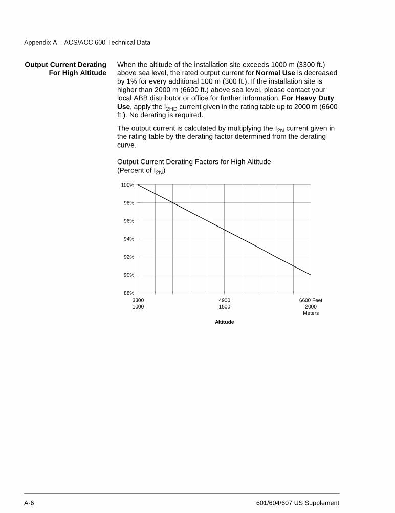
Output Current DeratingFor High Altitude
When the altitude of the installation site exceeds 1000 m (3300 ft.)above sea level, the rated output current for Normal Use is decreasedby 1% for every additional 100 m (300 ft.). If the installation site ishigher than 2000 m (6600 ft.) above sea level, please contact yourlocal ABB distributor or office for further information. For Heavy DutyUse, apply the I2HD current given in the rating table up to 2000 m (6600ft.). No derating is required.
The output current is calculated by multiplying the I2N current given inthe rating table by the derating factor determined from the deratingcurve.
Output Current Derating Factors for High Altitude(Percent of I2N)
88%
90%
92%
94%
96%
98%
100%
33001000
49001500
6600 Feet2000
Meters
Altitude
Appendix A – ACS/ACC 600 Technical Data
601/604/607 US Supplement A-7
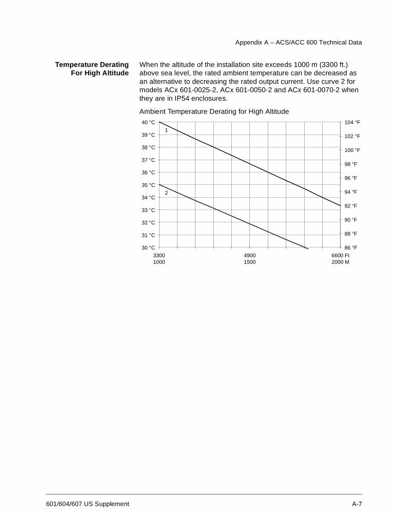
Temperature DeratingFor High Altitude
When the altitude of the installation site exceeds 1000 m (3300 ft.)above sea level, the rated ambient temperature can be decreased asan alternative to decreasing the rated output current. Use curve 2 formodels ACx 601-0025-2, ACx 601-0050-2 and ACx 601-0070-2 whenthey are in IP54 enclosures.
Ambient Temperature Derating for High Altitude
30 °C
31 °C
32 °C
33 °C
34 °C
35 °C
36 °C
37 °C
38 °C
39 °C
40 °C
33001000
49001500
6600 Ft2000 M
86 °F
88 °F
90 °F
92 °F
94 °F
96 °F
98 °F
100 °F
102 °F
104 °F1
2
Appendix A – ACS/ACC 600 Technical Data
A-8 601/604/607 US Supplement
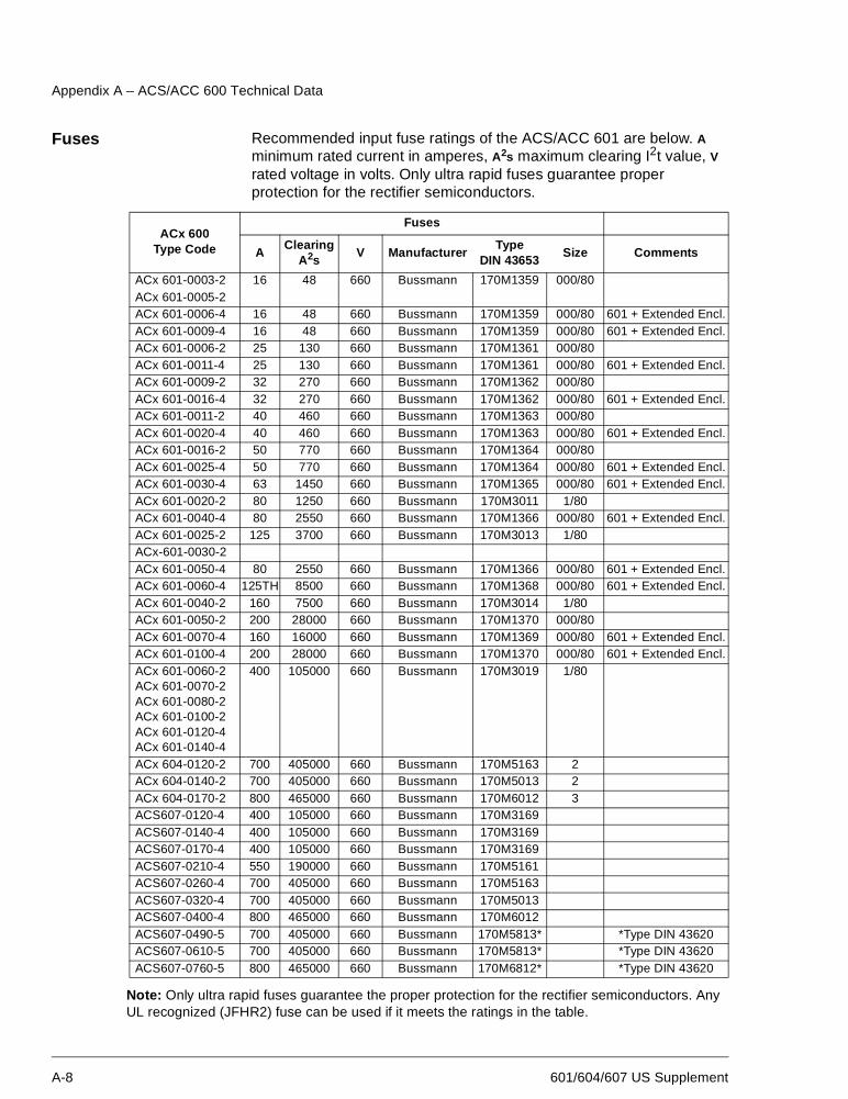
Fuses Recommended input fuse ratings of the ACS/ACC 601 are below. Aminimum rated current in amperes, A2s maximum clearing I2t value, Vrated voltage in volts. Only ultra rapid fuses guarantee properprotection for the rectifier semiconductors.
Note: Only ultra rapid fuses guarantee the proper protection for the rectifier semiconductors. AnyUL recognized (JFHR2) fuse can be used if it meets the ratings in the table.
ACx 600Type Code
Fuses
AClearing
A2sV Manufacturer
TypeDIN 43653
Size Comments
ACx 601-0003-2 16 48 660 Bussmann 170M1359 000/80ACx 601-0005-2ACx 601-0006-4 16 48 660 Bussmann 170M1359 000/80 601 + Extended Encl.ACx 601-0009-4 16 48 660 Bussmann 170M1359 000/80 601 + Extended Encl.ACx 601-0006-2 25 130 660 Bussmann 170M1361 000/80ACx 601-0011-4 25 130 660 Bussmann 170M1361 000/80 601 + Extended Encl.ACx 601-0009-2 32 270 660 Bussmann 170M1362 000/80ACx 601-0016-4 32 270 660 Bussmann 170M1362 000/80 601 + Extended Encl.ACx 601-0011-2 40 460 660 Bussmann 170M1363 000/80ACx 601-0020-4 40 460 660 Bussmann 170M1363 000/80 601 + Extended Encl.ACx 601-0016-2 50 770 660 Bussmann 170M1364 000/80ACx 601-0025-4 50 770 660 Bussmann 170M1364 000/80 601 + Extended Encl.ACx 601-0030-4 63 1450 660 Bussmann 170M1365 000/80 601 + Extended Encl.ACx 601-0020-2 80 1250 660 Bussmann 170M3011 1/80ACx 601-0040-4 80 2550 660 Bussmann 170M1366 000/80 601 + Extended Encl.ACx 601-0025-2 125 3700 660 Bussmann 170M3013 1/80ACx-601-0030-2ACx 601-0050-4 80 2550 660 Bussmann 170M1366 000/80 601 + Extended Encl.ACx 601-0060-4 125TH 8500 660 Bussmann 170M1368 000/80 601 + Extended Encl.ACx 601-0040-2 160 7500 660 Bussmann 170M3014 1/80ACx 601-0050-2 200 28000 660 Bussmann 170M1370 000/80ACx 601-0070-4 160 16000 660 Bussmann 170M1369 000/80 601 + Extended Encl.ACx 601-0100-4 200 28000 660 Bussmann 170M1370 000/80 601 + Extended Encl.ACx 601-0060-2ACx 601-0070-2ACx 601-0080-2ACx 601-0100-2ACx 601-0120-4ACx 601-0140-4
400 105000 660 Bussmann 170M3019 1/80
ACx 604-0120-2 700 405000 660 Bussmann 170M5163 2ACx 604-0140-2 700 405000 660 Bussmann 170M5013 2ACx 604-0170-2 800 465000 660 Bussmann 170M6012 3ACS607-0120-4 400 105000 660 Bussmann 170M3169ACS607-0140-4 400 105000 660 Bussmann 170M3169ACS607-0170-4 400 105000 660 Bussmann 170M3169ACS607-0210-4 550 190000 660 Bussmann 170M5161ACS607-0260-4 700 405000 660 Bussmann 170M5163ACS607-0320-4 700 405000 660 Bussmann 170M5013ACS607-0400-4 800 465000 660 Bussmann 170M6012ACS607-0490-5 700 405000 660 Bussmann 170M5813* *Type DIN 43620ACS607-0610-5 700 405000 660 Bussmann 170M5813* *Type DIN 43620ACS607-0760-5 800 465000 660 Bussmann 170M6812* *Type DIN 43620
Appendix A – ACS/ACC 600 Technical Data
601/604/607 US Supplement A-9
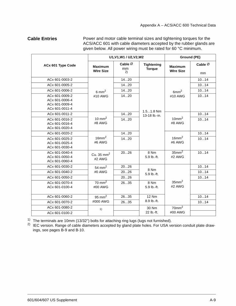
Cable Entries Power and motor cable terminal sizes and tightening torques for theACS/ACC 601 with cable diameters accepted by the rubber glands aregiven below. All power wiring must be rated for 60 °C minimum.
1) The terminals are 10mm (13/32”) bolts for attaching ring lugs (lugs not furnished).2) IEC version. Range of cable diameters accepted by gland plate holes. For USA version conduit plate draw-
ings, see pages B-9 and B-10.
ACx 601 Type Code
U1,V1,W1 / U2,V2,W2 Ground (PE)
MaximumWIre Size
Cable Ømm
2)
TighteningTorque
MaximumWIre Size
Cable Ø
mm
ACx 601-0003-2
6 mm2
#10 AWG
14...20
1.5...1.8 Nm13-18 lb.-in.
6mm2
#10 AWG
10...14
ACx 601-0005-2 14...20 10...14
ACx 601-0006-2 14...20 10...14
ACx 601-0009-2ACx 601-0006-4ACx 601-0009-4ACx 601-0011-4
14...20 10...14
ACx 601-0011-210 mm2
#8 AWG
14...2010mm2
#8 AWG
10...14
ACx 601-0016-2ACx 601-0016-4ACx 601-0020-4
14...20 10...14
ACx 601-0020-216mm2
#6 AWG
14...2016mm2
#6 AWG
10...14
ACx 601-0025-2ACx 601-0025-4ACx 601-0030-4
14...20 10...14
ACx 601-0040-4ACx 601-0050-4ACx 601-0060-4
Cu. 35 mm2
#2 AWG
20...26 8 Nm5.9 lb.-ft.
35mm2
#2 AWG10...14
ACx 601-0030-2 54 mm2
#0 AWG
20...268 Nm
5.9 lb.-ft.
35mm2
#2 AWG
10...14
ACx 601-0040-2 20...26 10...14
ACx 601-0050-2 20...26 10...14
ACx 601-0070-4ACx 601-0100-4
70 mm2
#00 AWG26...35 8 Nm
5.9 lb.-ft.
ACx 601-0060-2 95 mm2
#000 AWG26...35 12 Nm
8.9 lb.-ft.10...14
ACx 601-0070-2 26...35 10...14
ACx 601-0080-2 1) 30 Nm22 lb.-ft.
70mm2
#00 AWGACx 601-0100-2
Appendix A – ACS/ACC 600 Technical Data
A-10 601/604/607 US Supplement
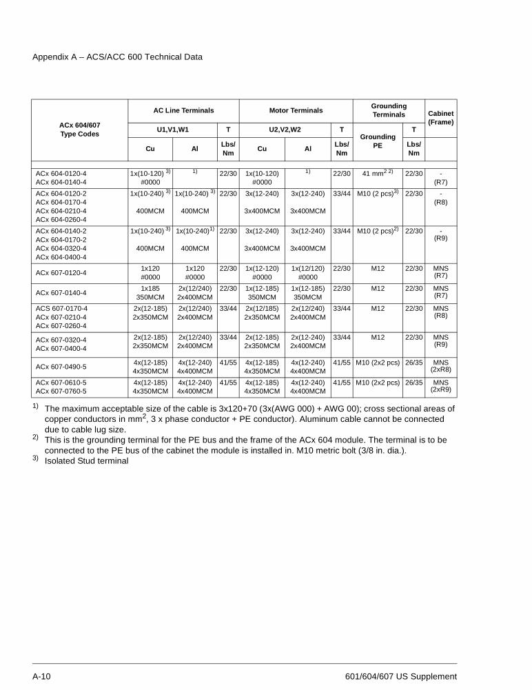
1) The maximum acceptable size of the cable is 3x120+70 (3x(AWG 000) + AWG 00); cross sectional areas ofcopper conductors in mm2, 3 x phase conductor + PE conductor). Aluminum cable cannot be connecteddue to cable lug size.
2) This is the grounding terminal for the PE bus and the frame of the ACx 604 module. The terminal is to beconnected to the PE bus of the cabinet the module is installed in. M10 metric bolt (3/8 in. dia.).
3) Isolated Stud terminal
ACx 604/607Type Codes
AC Line Terminals Motor TerminalsGroundingTerminals Cabinet
(Frame)U1,V1,W1 T U2,V2,W2 T
GroundingPE
T
Cu AlLbs/Nm
Cu AlLbs/Nm
Lbs/Nm
ACx 604-0120-4ACx 604-0140-4
1x(10-120) 3)
#0000
1) 22/30 1x(10-120)#0000
1) 22/30 41 mm2 2) 22/30 -(R7)
ACx 604-0120-2ACx 604-0170-4ACx 604-0210-4ACx 604-0260-4
1x(10-240) 3)
400MCM
1x(10-240) 3)
400MCM
22/30 3x(12-240)
3x400MCM
3x(12-240)
3x400MCM
33/44 M10 (2 pcs)3) 22/30 -(R8)
ACx 604-0140-2ACx 604-0170-2ACx 604-0320-4ACx 604-0400-4
1x(10-240) 3)
400MCM
1x(10-240)1)
400MCM
22/30 3x(12-240)
3x400MCM
3x(12-240)
3x400MCM
33/44 M10 (2 pcs)2) 22/30 -(R9)
ACx 607-0120-41x120#0000
1x120#0000
22/30 1x(12-120)#0000
1x(12/120)#0000
22/30 M12 22/30 MNS(R7)
ACx 607-0140-41x185
350MCM2x(12/240)2x400MCM
22/30 1x(12-185)350MCM
1x(12-185)350MCM
22/30 M12 22/30 MNS(R7)
ACS 607-0170-4ACx 607-0210-4ACx 607-0260-4
2x(12-185)2x350MCM
2x(12/240)2x400MCM
33/44 2x(12/185)2x350MCM
2x(12/240)2x400MCM
33/44 M12 22/30 MNS(R8)
ACx 607-0320-4ACx 607-0400-4
2x(12-185)2x350MCM
2x(12/240)2x400MCM
33/44 2x(12-185)2x350MCM
2x(12-240)2x400MCM
33/44 M12 22/30 MNS(R9)
ACx 607-0490-54x(12-185)4x350MCM
4x(12-240)4x400MCM
41/55 4x(12-185)4x350MCM
4x(12-240)4x400MCM
41/55 M10 (2x2 pcs) 26/35 MNS(2xR8)
ACx 607-0610-5ACx 607-0760-5
4x(12-185)4x350MCM
4x(12-240)4x400MCM
41/55 4x(12-185)4x350MCM
4x(12-240)4x400MCM
41/55 M10 (2x2 pcs) 26/35 MNS(2xR9)
Appendix A – ACS/ACC 600 Technical Data
601/604/607 US Supplement A-11
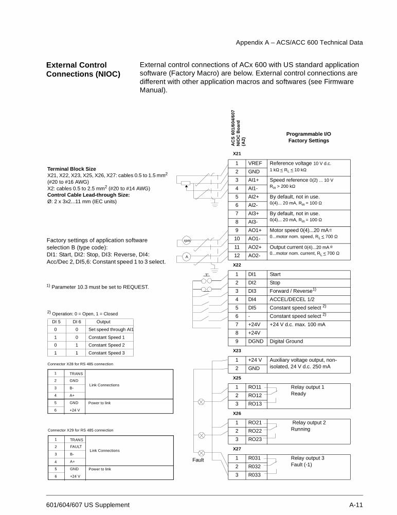
External ControlConnections (NIOC)
External control connections of ACx 600 with US standard applicationsoftware (Factory Macro) are below. External control connections aredifferent with other application macros and softwares (see FirmwareManual).
AC
S60
1/60
4/60
7N
IOC
Bo
ard
(A2)
Programmable I/OFactory Settings
X21
1 VREF Reference voltage 10 V d.c.1 kΩ < RL < 10 kΩ2 GND
3 AI1+ Speed reference 0(2) ... 10 VRin > 200 kΩ4 AI1-
5 AI2+ By default, not in use.0(4)... 20 mA, Rin = 100 Ω6 AI2-
7 AI3+ By default, not in use.0(4)... 20 mA, Rin = 100 Ω8 AI3-
9 AO1+ Motor speed 0(4)...20 mA0...motor nom. speed, RL < 700 Ω10 AO1-
11 AO2+ Output current 0(4)...20 mA0...motor nom. current, RL < 700 Ω12 AO2-
X22
1 DI1 Start
2 DI2 Stop
3 DI3 Forward / Reverse1)
4 DI4 ACCEL/DECEL 1/2
5 DI5 Constant speed select 2)
6 - Constant speed select 2)
7 +24V +24 V d.c. max. 100 mA
8 +24V
9 DGND Digital Ground
X23
1 +24 V Auxiliary voltage output, non-isolated, 24 V d.c. 250 mA2 GND
X25
1 RO11 Relay output 1Ready2 RO12
3 RO13
X26
1 RO21 Relay output 2Running2 RO22
3 RO23
X27
1 R031 Relay output 3Fault (-1)2 R032
3 R033
=
=
2) Operation: 0 = Open, 1 = Closed
DI 5 DI 6 Output
0
1
0
1
0
0
1
1
Set speed through AI1
Constant Speed 1
Constant Speed 2
Constant Speed 3
1
2
3
5
6
TRANS
Power to link
Link ConnectionsB-
A+
GND
+24 V
Connector X29 for RS 485 connection
4
FAULT
1
2
3
4
5
6
TRANS
Power to link
Link ConnectionsGND
B-
A+
GND
+24 V
Connector X28 for RS 485 connection
1) Parameter 10.3 must be set to REQUEST.
Terminal Block SizeX21, X22, X23, X25, X26, X27: cables 0.5 to 1.5 mm2
(#20 to #16 AWG)X2: cables 0.5 to 2.5 mm2 (#20 to #14 AWG)Control Cable Lead-through Size:Ø: 2 x 3x2...11 mm (IEC units)
Factory settings of application softwareselection B (type code):DI1: Start, DI2: Stop, DI3: Reverse, DI4:Acc/Dec 2, DI5,6: Constant speed 1 to 3 select.
Fault
A
rpm
Appendix A – ACS/ACC 600 Technical Data
A-12 601/604/607 US Supplement
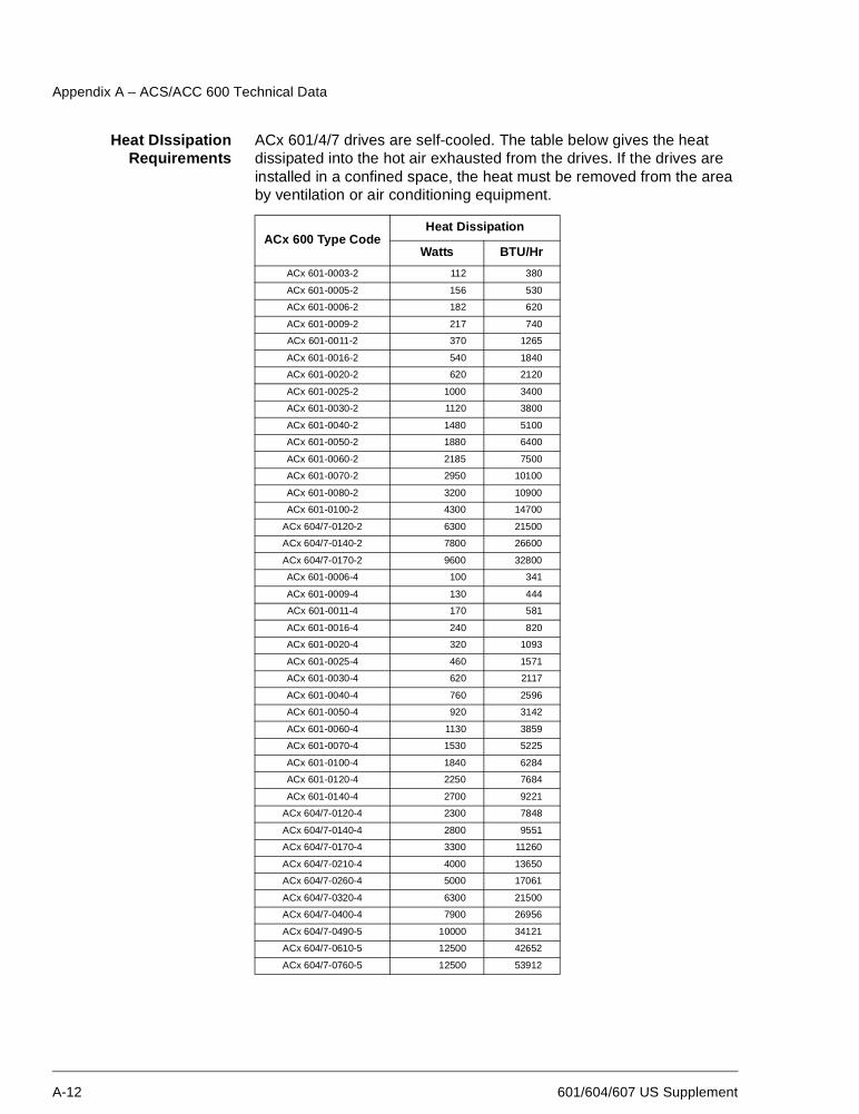
Heat DIssipationRequirements
ACx 601/4/7 drives are self-cooled. The table below gives the heatdissipated into the hot air exhausted from the drives. If the drives areinstalled in a confined space, the heat must be removed from the areaby ventilation or air conditioning equipment.
ACx 600 Type CodeHeat Dissipation
Watts BTU/Hr
ACx 601-0003-2 112 380
ACx 601-0005-2 156 530
ACx 601-0006-2 182 620
ACx 601-0009-2 217 740
ACx 601-0011-2 370 1265
ACx 601-0016-2 540 1840
ACx 601-0020-2 620 2120
ACx 601-0025-2 1000 3400
ACx 601-0030-2 1120 3800
ACx 601-0040-2 1480 5100
ACx 601-0050-2 1880 6400
ACx 601-0060-2 2185 7500
ACx 601-0070-2 2950 10100
ACx 601-0080-2 3200 10900
ACx 601-0100-2 4300 14700
ACx 604/7-0120-2 6300 21500
ACx 604/7-0140-2 7800 26600
ACx 604/7-0170-2 9600 32800
ACx 601-0006-4 100 341
ACx 601-0009-4 130 444
ACx 601-0011-4 170 581
ACx 601-0016-4 240 820
ACx 601-0020-4 320 1093
ACx 601-0025-4 460 1571
ACx 601-0030-4 620 2117
ACx 601-0040-4 760 2596
ACx 601-0050-4 920 3142
ACx 601-0060-4 1130 3859
ACx 601-0070-4 1530 5225
ACx 601-0100-4 1840 6284
ACx 601-0120-4 2250 7684
ACx 601-0140-4 2700 9221
ACx 604/7-0120-4 2300 7848
ACx 604/7-0140-4 2800 9551
ACx 604/7-0170-4 3300 11260
ACx 604/7-0210-4 4000 13650
ACx 604/7-0260-4 5000 17061
ACx 604/7-0320-4 6300 21500
ACx 604/7-0400-4 7900 26956
ACx 604/7-0490-5 10000 34121
ACx 604/7-0610-5 12500 42652
ACx 604/7-0760-5 12500 53912
Appendix A – ACS/ACC 600 Technical Data
601/604/607 US Supplement A-13
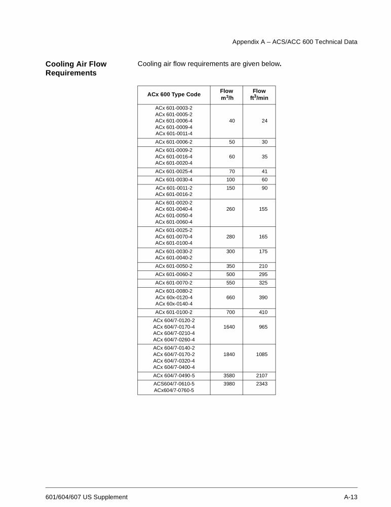
Cooling Air FlowRequirements
Cooling air flow requirements are given below.
ACx 600 Type CodeFlowm3/h
Flowft3/min
ACx 601-0003-2ACx 601-0005-2ACx 601-0006-4ACx 601-0009-4ACx 601-0011-4
40 24
ACx 601-0006-2 50 30
ACx 601-0009-2ACx 601-0016-4ACx 601-0020-4
60 35
ACx 601-0025-4 70 41
ACx 601-0030-4 100 60
ACx 601-0011-2ACx 601-0016-2
150 90
ACx 601-0020-2ACx 601-0040-4ACx 601-0050-4ACx 601-0060-4
260 155
ACx 601-0025-2ACx 601-0070-4ACx 601-0100-4
280 165
ACx 601-0030-2ACx 601-0040-2
300 175
ACx 601-0050-2 350 210
ACx 601-0060-2 500 295
ACx 601-0070-2 550 325
ACx 601-0080-2ACx 60x-0120-4ACx 60x-0140-4
660 390
ACx 601-0100-2 700 410
ACx 604/7-0120-2ACx 604/7-0170-4ACx 604/7-0210-4ACx 604/7-0260-4
1640 965
ACx 604/7-0140-2ACx 604/7-0170-2ACx 604/7-0320-4ACx 604/7-0400-4
1840 1085
ACx 604/7-0490-5 3580 2107
ACS604/7-0610-5ACx604/7-0760-5
3980 2343
Appendix A – ACS/ACC 600 Technical Data
A-14 601/604/607 US Supplement
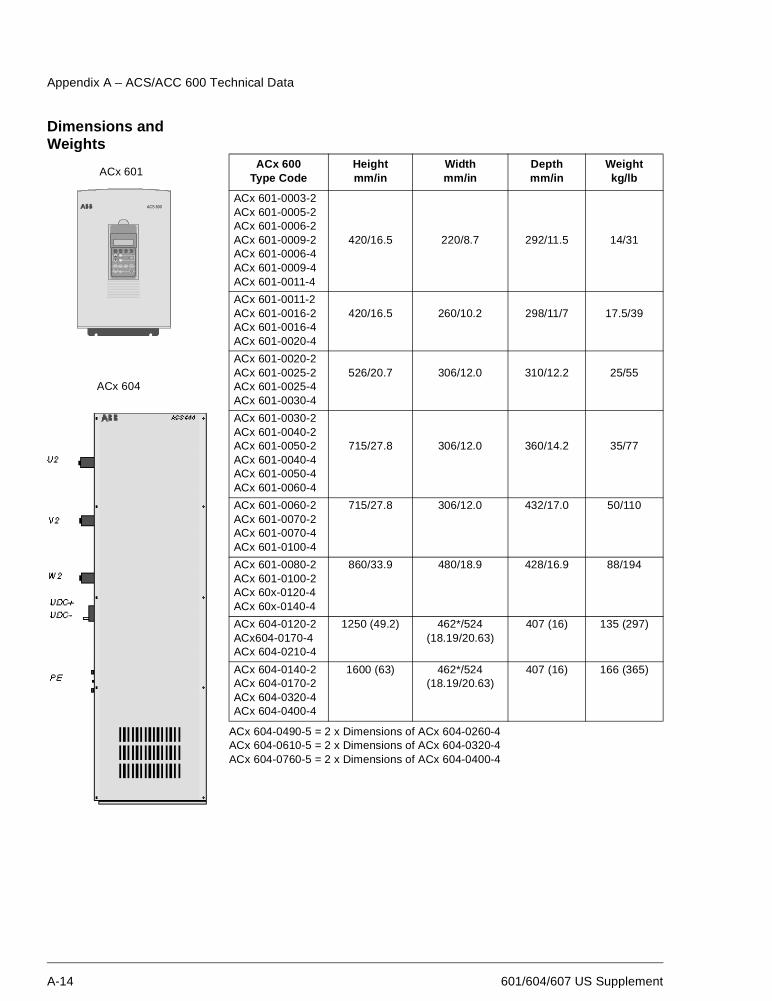
Dimensions andWeights
ACx 604-0490-5 = 2 x Dimensions of ACx 604-0260-4ACx 604-0610-5 = 2 x Dimensions of ACx 604-0320-4ACx 604-0760-5 = 2 x Dimensions of ACx 604-0400-4
ACx 600Type Code
Heightmm/in
Widthmm/in
Depthmm/in
Weightkg/lb
ACx 601-0003-2ACx 601-0005-2ACx 601-0006-2ACx 601-0009-2ACx 601-0006-4ACx 601-0009-4ACx 601-0011-4
420/16.5 220/8.7 292/11.5 14/31
ACx 601-0011-2ACx 601-0016-2ACx 601-0016-4ACx 601-0020-4
420/16.5 260/10.2 298/11/7 17.5/39
ACx 601-0020-2ACx 601-0025-2ACx 601-0025-4ACx 601-0030-4
526/20.7 306/12.0 310/12.2 25/55
ACx 601-0030-2ACx 601-0040-2ACx 601-0050-2ACx 601-0040-4ACx 601-0050-4ACx 601-0060-4
715/27.8 306/12.0 360/14.2 35/77
ACx 601-0060-2ACx 601-0070-2ACx 601-0070-4ACx 601-0100-4
715/27.8 306/12.0 432/17.0 50/110
ACx 601-0080-2ACx 601-0100-2ACx 60x-0120-4ACx 60x-0140-4
860/33.9 480/18.9 428/16.9 88/194
ACx 604-0120-2ACx604-0170-4ACx 604-0210-4
1250 (49.2) 462*/524(18.19/20.63)
407 (16) 135 (297)
ACx 604-0140-2ACx 604-0170-2ACx 604-0320-4ACx 604-0400-4
1600 (63) 462*/524(18.19/20.63)
407 (16) 166 (365)
AC T PA R FU NC D R I VE
E N TE R
L OC
R E M
R ES E T R EF
ACS 600
ACx 601
ACx 604
Appendix A – ACS/ACC 600 Technical Data
601/604/607 US Supplement A-15
Input PowerConnection
Voltage (U1):208/230/240 VAC 3-phase ± 10%
380/400/514/440/460/480/500 VAC 3-phase + 10%
Short Circuit Capability: The rated short time withstand current ofACx 600 is 50 kA 1s.
Frequency: 48 to 63 Hz, maximum rate of change 17%/s
Imbalance: Max. ± 3% of nominal phase to phase input voltage
Fundamental Power Factor (cos ϕ1): 0.97 (at nominal load)
Motor Connection Voltage (U2): 0 to U1, 3-phase symmetrical
Frequency: DTC mode: 0 to 3.2 · fFWP. Maximum frequency 300 Hz.
fFWP =
fFWP: Frequency at field weakening point; UNmains: Mains voltage;UNmotor: Rated motor voltage; fNmotor: Rated motor frequency
Scalar Control mode: 0 to 300 HzWith dv/dt Filter (DTC and Scalar Control modes): 0 to 120 Hz
Frequency Resolution: 0.01 Hz
Continuous Current: 1.0 · I2N (normal use)1.0 · I2hd (heavy-duty use)
Short Term Overload Capacity (1 min/10 min): I2Nmax = 1.1 · I2NI2hdmax = 1.5 · I2hd
Peak Overload Capacity (2 s/15 s):1.5 · I2N2.0 · I2hd
Power Limit: 1.5 · Phd
Overcurrent Trip: 3.5 · I2hd
Field Weakening Point: 8 to 300 Hz
Switching Frequency: 3 kHz (average).
Maximum Recommended Motor Cable Length: 300 m (980 ft.). Thisis the cumulative length in case of parallel connected motors. For ACx601-0003-2 to ACx 601-0016-2, if the motor cable length exceeds 70meters (230 ft.), an ABB representative should be consulted.
Bearings of motors larger than 90 kW (125 Hp): Insulated bearing atnon-driven end is recommended.
Efficiency and Cooling Efficiency: Approximately 98% at nominal power level
Cooling Method: Internal fan, flow direction from the bottom to the top
UNmains
UNmotor· fNmotor
Appendix A – ACS/ACC 600 Technical Data
A-16 601/604/607 US Supplement
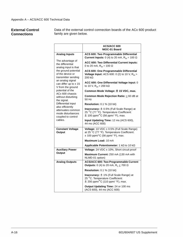
External ControlConnections
Data of the external control connection boards of the ACx 600 productfamily are given below.
ACS/ACC 600NIOC-01 Board
Analog Inputs
The advantage ofthe differentialanalog input is thatthe ground potentialof the device ortransmitter sendingan analog signalcan differ up to ± 15V from the groundpotential of theACx 600 chassiswithout disturbingthe signal.Differential inputalso efficientlyattenuates commonmode disturbancescoupled to controlcables.
ACS 600: Two Programmable DifferentialCurrent Inputs: 0 (4) to 20 mA, Rin = 100 Ω
ACC 600: Two Differential Current Inputs:0 to 20 mA, Rin = 100 Ω
ACS 600: One Programmable DifferentialVoltage Input: ACS 600: 0 (2) to 10 V, Rin >200 kΩ
ACC 600: One Differential Voltage Input: 0to 10 V, Rin > 200 kΩ
Common Mode Voltage: ± 15 VDC, max.
Common Mode Rejection Ratio: > 60 dB at50 Hz
Resolution: 0.1 % (10 bit)
Inaccuracy: ± 0.5% (Full Scale Range) at25 °C (77 °F). Temperature Coefficient:± 100 ppm/°C (56 ppm/ °F), max.
Input Updating Time: 12 ms (ACS 600),44 ms (ACC 600)
Constant VoltageOutput
Voltage: 10 VDC ± 0.5% (Full Scale Range)at 25 °C (77 °F). Temperature Coefficient:± 100 ppm/°C (56 ppm/ °F), max.
Maximum Load: 10 mA
Applicable Potentiometer: 1 kΩ to 10 kΩAuxiliary PowerOutput
Voltage: 24 VDC ± 10%, Short circuit proof
Maximum Current: 250 mA (130 mA withNLMD-01 option)
Analog Outputs ACS/ACC 600: Two Programmable CurrentOutputs: 0 (4) to 20 mA, RL < 700 Ω
Resolution: 0.1 % (10 bit)
Inaccuracy: ± 1% (Full Scale Range) at25 °C. Temperature Coefficient:± 200 ppm/°C (110 ppm/ °F), max.
Output Updating Time: 24 or 100 ms(ACS 600), 44 ms (ACC 600)
Appendix A – ACS/ACC 600 Technical Data
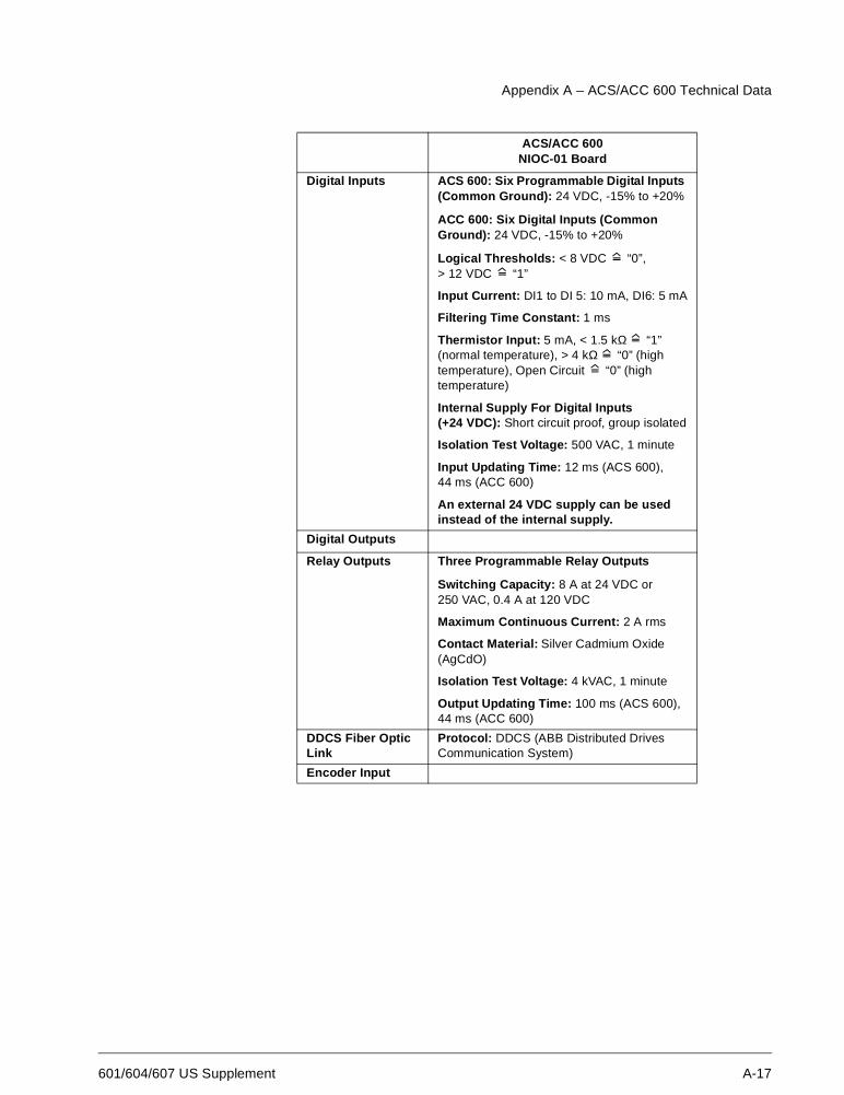
601/604/607 US Supplement A-17
Digital Inputs ACS 600: Six Programmable Digital Inputs(Common Ground): 24 VDC, -15% to +20%
ACC 600: Six Digital Inputs (CommonGround): 24 VDC, -15% to +20%
Logical Thresholds: < 8 VDC “0”,> 12 VDC “1”
Input Current: DI1 to DI 5: 10 mA, DI6: 5 mA
Filtering Time Constant: 1 ms
Thermistor Input: 5 mA, < 1.5 kΩ “1”(normal temperature), > 4 kΩ “0” (hightemperature), Open Circuit “0” (hightemperature)
Internal Supply For Digital Inputs(+24 VDC): Short circuit proof, group isolated
Isolation Test Voltage: 500 VAC, 1 minute
Input Updating Time: 12 ms (ACS 600),44 ms (ACC 600)
An external 24 VDC supply can be usedinstead of the internal supply.
Digital Outputs
Relay Outputs Three Programmable Relay Outputs
Switching Capacity: 8 A at 24 VDC or250 VAC, 0.4 A at 120 VDC
Maximum Continuous Current: 2 A rms
Contact Material: Silver Cadmium Oxide(AgCdO)
Isolation Test Voltage: 4 kVAC, 1 minute
Output Updating Time: 100 ms (ACS 600),44 ms (ACC 600)
DDCS Fiber OpticLink
Protocol: DDCS (ABB Distributed DrivesCommunication System)
Encoder Input
ACS/ACC 600NIOC-01 Board
Appendix A – ACS/ACC 600 Technical Data
A-18 601/604/607 US Supplement
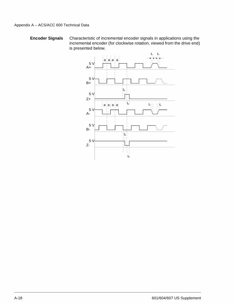
Encoder Signals Characteristic of incremental encoder signals in applications using theincremental encoder (for clockwise rotation, viewed from the drive end)is presented below.
a a a a
A+5 V
5 V
5 V
5 V
5 V
5 V
B+
Z+
A-
B-
Z-
a a a a
tv tv
td
td
td
td
tv tv
Appendix A – ACS/ACC 600 Technical Data
601/604/607 US Supplement A-19
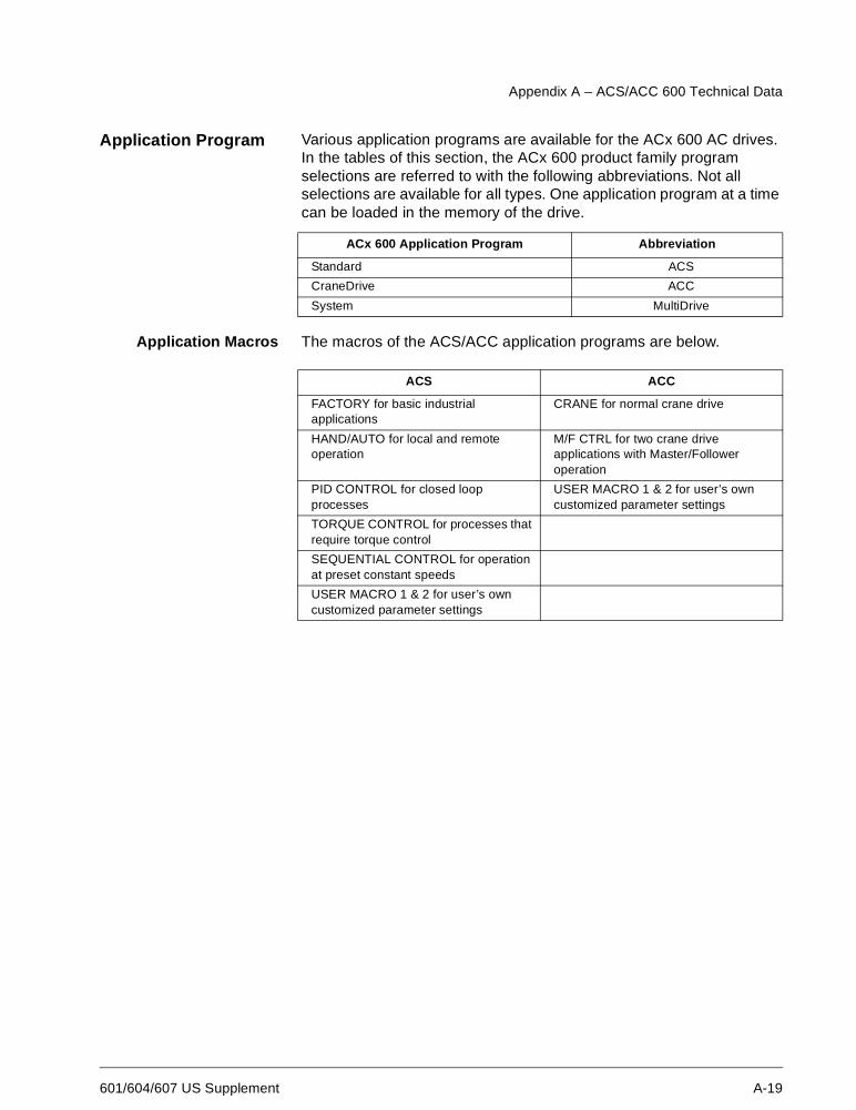
Application Program Various application programs are available for the ACx 600 AC drives.In the tables of this section, the ACx 600 product family programselections are referred to with the following abbreviations. Not allselections are available for all types. One application program at a timecan be loaded in the memory of the drive.
Application Macros The macros of the ACS/ACC application programs are below.
ACx 600 Application Program Abbreviation
Standard ACS
CraneDrive ACC
System MultiDrive
ACS ACC
FACTORY for basic industrialapplications
CRANE for normal crane drive
HAND/AUTO for local and remoteoperation
M/F CTRL for two crane driveapplications with Master/Followeroperation
PID CONTROL for closed loopprocesses
USER MACRO 1 & 2 for user’s owncustomized parameter settings
TORQUE CONTROL for processes thatrequire torque control
SEQUENTIAL CONTROL for operationat preset constant speeds
USER MACRO 1 & 2 for user’s owncustomized parameter settings
Appendix A – ACS/ACC 600 Technical Data
A-20 601/604/607 US Supplement
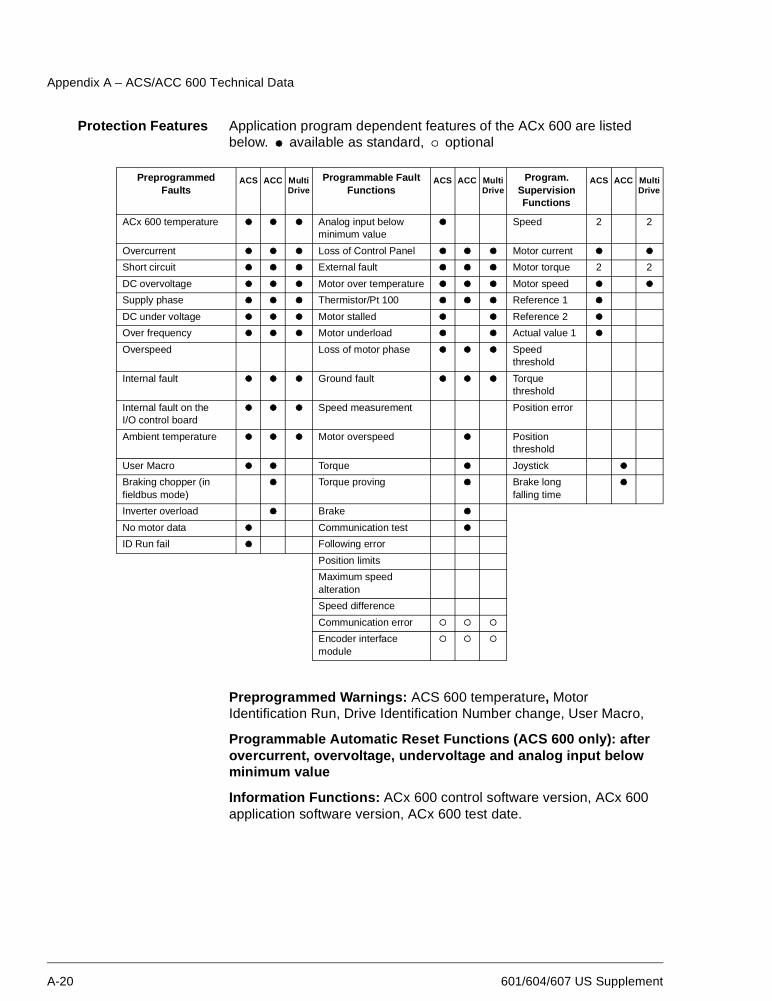
Protection Features Application program dependent features of the ACx 600 are listedbelow. available as standard, optional
Preprogrammed Warnings: ACS 600 temperature, MotorIdentification Run, Drive Identification Number change, User Macro,
Programmable Automatic Reset Functions (ACS 600 only): afterovercurrent, overvoltage, undervoltage and analog input belowminimum value
Information Functions: ACx 600 control software version, ACx 600application software version, ACx 600 test date.
PreprogrammedFaults
ACS ACC MultiDrive
Programmable FaultFunctions
ACS ACC MultiDrive
Program.SupervisionFunctions
ACS ACC MultiDrive
ACx 600 temperature Analog input belowminimum value
Speed 2 2
Overcurrent Loss of Control Panel Motor current
Short circuit External fault Motor torque 2 2
DC overvoltage Motor over temperature Motor speed
Supply phase Thermistor/Pt 100 Reference 1
DC under voltage Motor stalled Reference 2
Over frequency Motor underload Actual value 1
Overspeed Loss of motor phase Speedthreshold
Internal fault Ground fault Torquethreshold
Internal fault on theI/O control board
Speed measurement Position error
Ambient temperature Motor overspeed Positionthreshold
User Macro Torque Joystick
Braking chopper (infieldbus mode)
Torque proving Brake longfalling time
Inverter overload Brake
No motor data Communication test
ID Run fail Following error
Position limits
Maximum speedalteration
Speed difference
Communication error
Encoder interfacemodule
Appendix A – ACS/ACC 600 Technical Data
601/604/607 US Supplement A-21
Equipment Warrantyand Liability
General: ABB warrants the Equipment supplied by ABB against defects in material andworkmanship for a period of twelve (12) months after installation or twenty four (24)months from date of shipment from factory, whichever first occurs.
Should any failure to conform with the applicable warranties appear during thespecified periods under normal and proper use and provided the Equipment has beenproperly stored, installed, operated and maintained, and if given prompt notice byPurchaser, ABB shall correct such nonconformity, at its option; by (1) repair orreplacement of the nonconforming equipment or parts thereof. Repairs orreplacements pursuant to warranty shall not renew or extend the applicable originalequipment warranty period, provided however, that any such repairs or replacement ofequipment or parts thereof shall be warranted for the time remaining of the originalwarranty period or 30 days, whichever is longer.
ABB shall not be responsible for providing working access to the defect, includingdisassembly and reassembly of equipment or for providing transportation to and fromrepair or factory facility, all of which shall be at Purchaser’s risk and expense.
These warranties shall not apply to any Equipment or parts thereof which (1) havebeen improperly repaired or altered; (2) have been subjected to misuse, negligence oraccident; (3) have been used in a manner contrary to ABB’s instructions; (4) arecomprised of materials provided or designed stipulated by Purchaser; or (5) are usedequipment.
The foregoing warranties are exclusive and in lieu of all other warranties of quality andperformance, written, oral or implied, and all other warranties including any impliedwarranties of merchantability or fitness for a particular purpose are hereby disclaimedby ABB and all equipment manufacturers.
Correction of nonconformities in the manner and for the period of time provided aboveshall be the Purchaser’s exclusive remedy and shall constitute fulfilment of all liabilitiesof ABB and any Equipment manufacturer (including any liability for direct, indirect,special, incidental or consequential damages) whether in warranty, contract,negligence, tort, strict liability, or otherwise with respect to any nonconformance of ordefect or deficiency in the equipment supplied or services furnished hereunder.
Limitation of Liability IN NO EVENT SHALL ABB, ITS SUPPLIERS OR SUBCONTRACTORS BE LIABLEFOR SPECIAL, INDIRECT, INCIDENTAL OR CONSEQUENTIAL DAMAGES,WHETHER IN CONTRACT, WARRANTY, TORT, NEGLIGENCE, STRICT LIABILITYOR OTHERWISE, including, but not limited to loss of profits or revenue, loss of use ofthe Equipment or any associated equipment, cost of capital, cost of substituteequipment, facilities or services, downtime costs, delays, or claims of customers of thePurchaser or other third parties for such or other damages. ABB’s liability on any claimwhether in contract, warranty, negligence, tort, strict liability, or otherwise for any loss ordamage arising out of, connected with, or resulting from the contract or theperformance or breach thereof, or from the design, manufacture, sale, delivery, resale,repair, replacement, installation, technical direction of installation, inspection, operationor use of any equipment covered by or in connection therewith, shall in no case exceedthe purchase price of the Equipment or part thereof or services which give rise to theClaim.
All clauses of action against ABB arising out of or relating to the contract or theperformance or breach hereof shall expire unless brought within one year of the time ofaccrual thereof.
In no event, regardless of cause, shall ABB assume responsibility for or be liable forpenalties or penalty clauses of any description or for indemnification of customer orothers for costs, damages, or expenses each arising out of or related to the goods orservices of the order.
Your local distributor or ABB office may hold different guarantee details, which arespecified in the sales terms, conditions, or guarantee terms. These terms are availableon request.
Appendix A – ACS/ACC 600 Technical Data
A-22 601/604/607 US Supplement
If you have any questions concerning your ABB drive, please contact the localdistributor or ABB office. The technical data, information and specifications are valid atthe time of printing. The manufacturer reserves the right to modifications without priornotice.
601/604/607 US Supplement B-1
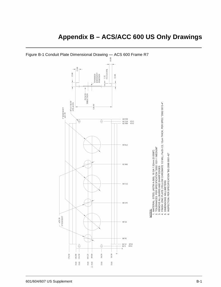
Appendix B – ACS/ACC 600 US Only Drawings
Figure B-1 Conduit Plate Dimensional Drawing — ACS 600 Frame R7
Appendix B – ACS/ACC 600 US Only Drawings
B-2 601/604/607 US Supplement
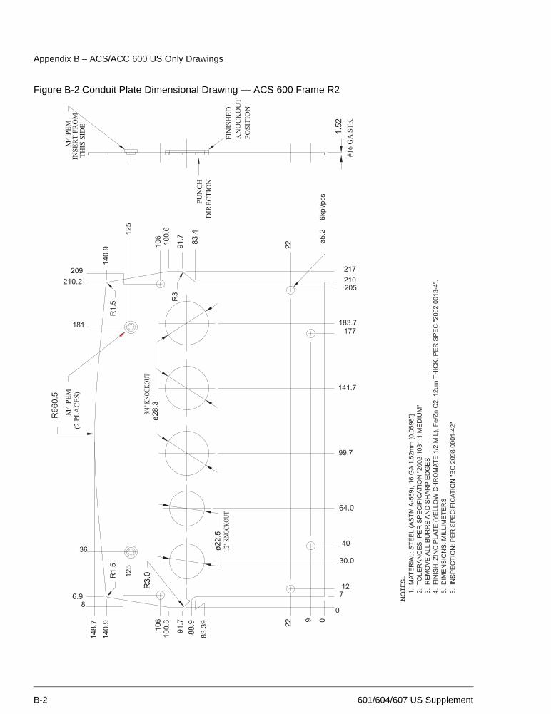
Figure B-2 Conduit Plate Dimensional Drawing — ACS 600 Frame R2
Appendix B – ACS/ACC 600 US Only Drawings
601/604/607 US Supplement B-3
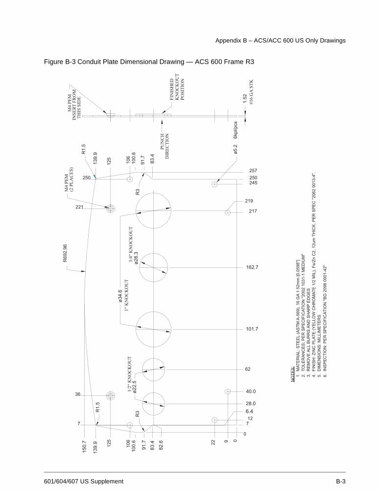
Figure B-3 Conduit Plate Dimensional Drawing — ACS 600 Frame R3
Appendix B – ACS/ACC 600 US Only Drawings
B-4 601/604/607 US Supplement
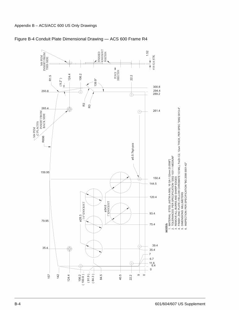
Figure B-4 Conduit Plate Dimensional Drawing — ACS 600 Frame R4
Appendix B – ACS/ACC 600 US Only Drawings
601/604/607 US Supplement B-5
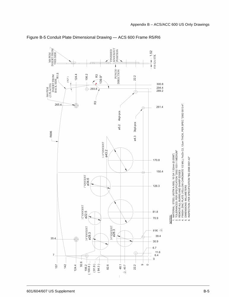
Figure B-5 Conduit Plate Dimensional Drawing — ACS 600 Frame R5/R6
Appendix B – ACS/ACC 600 US Only Drawings
B-6 601/604/607 US Supplement
This page is intentionally left blank.
Appendix B – ACS/ACC 600 US Only Drawings
601/604/607 US Supplement B-7
This page is intentionally left blank.

Appendix B – ACS/ACC 600 US Only Drawings
B-8 601/604/607 US Supplement
This page is intentionally left blank.

ABB Inc.Drives & Power Electronics16250 West Glendale DriveNew Berlin, WI 53151USATelephone: (262) 785-3416
(800) 243-4384Fax: (262) 785-8525
AC
S60
0-U
S-0
4S3A
UA
4890
02B
5071
R01
01 R
EV
CE
FF
EC
TIV
E: 1
1/12
/200
1
Related Documents