Corporate Office: Castro Valley, California Tel: 510-886-7826 Regional Office: Burbank, California Tel: 818-569-0234 Regional Office: Raleigh Durham, North Carolina Tel: 919-463-9995 NSCA University at infoComm08 20 June 2008 Las Vegas, Nevada Acoustics In Architecture (NW012) Steven J. Thorburn, PE, CTS-D, CTS-I Thorburn Associates, Inc [email protected] www.TA-Inc.com

Acoustics in Architecture
Oct 25, 2015
Welcome message from author
This document is posted to help you gain knowledge. Please leave a comment to let me know what you think about it! Share it to your friends and learn new things together.
Transcript
Corporate Office: Castro Valley, California Tel: 510-886-7826Regional Office: Burbank, California Tel: 818-569-0234Regional Office: Raleigh Durham, North Carolina Tel: 919-463-9995
NSCA University at infoComm08
20 June 2008 Las Vegas, Nevada
Acoustics In Architecture (NW012)
Steven J. Thorburn, PE, CTS-D, CTS-I
Thorburn Associates, Inc
[email protected] www.TA-Inc.com

Corporate Office: Castro Valley, California Tel: 510-886-7826 Regional Office: Burbank, California Tel: 818-569-0234 Regional Office: Raleigh Durham, North Carolina Tel: 919-463-9995
Firm Profile
THE COMPANY Thorburn Associates (TA) is a full service Acoustical Consulting and Technology Design and Engineering firm. TA was founded in 1992 by principals who have consulted on and managed over 2000 projects. We provide a full range of services which allow the client, architect, or end-user a single point of contact during design and construction. Our staff is comfortable providing traditional design or design/build services and is quite experienced with the partnering process. AWARDS TA principals have received three awards from the International Communications Industries Association: Professional Education and Training
Committee Award, 1996-97
First Place - Systems and Facilities Design, 1991, project: CSA Audiovisual Presentation Studio
Award for Systems and Facilities Design, 1990, project: City of Fremont’s Council Chambers Audiovisual Upgrade
Themed Entertainment Association THEA Award:
Awarded Themed Entertainment Association THEA Outstanding Achievement Award for Paramount's King's Island "Tomb Raider: The Ride" 2002
Universal Studios "Amazing Adventures of Spiderman," 2000
Universal Studios "Islands of Adventure," 2000
Columbus Center of Science and Technology (COSI), audio, video and control system engineering services and acoustical design 2000
Building of America Award, 2007, project: The Mountain View Senior Center
Northern California Region’s Most Important New Construction/ Renovation, 2007, project: San Francisco Federal Office Building, General Service Administration
AIA Winner of Architecture & Excellence Award, 2007, project: Plaza Apartments
PHILOSOPHY At TA we do whatever it takes to help make your project a success. Our consultants stay up-to-date on the latest technologies; develop in-house procedures to insure the quality of our work, such as custom computer programs to improve efficiency and provide quality control for redundant calculations. We utilize the latest automated equipment, such as the current release of AutoCAD with relational database overlays to produce design documents. Our office computers are fully networked. From design through construction, TA has the experience, knowledge and technology to make your project a success. Extensive laboratory and electronic test equipment allow us to efficiently document all aspects of acoustic designs. Our engineers can also create a Binauralization™ model (room simulation) which allows you to “hear” how your facility will sound before it is built. Our experience with the construction process provides the practical background experience necessary to recommend acoustical solutions that are both innovative and effective. Our Audiovisual System Design packages are complete and require minimal clarification during the construction phase. A relational database links project details directly to AutoCAD via drawing attributes. Electronic test equipment allows us to document all aspects of the audiovisual system design. This level of detail allows for true competitive bidding from installation contractors. Our knowledge of the construction process provides the background experience necessary to recommend audiovisual solutions that meet your needs. We feel it is imperative that our principals take an active role throughout a project. Only by being directly involved with projects can we be assured that you, our clients, are getting the level of quality you deserve and require.
FACILITY TYPES Presentation Facilities
Training and Board Rooms
Conference, Video, and Teleconfer-ence Rooms
Places of Worship and Theatres
Single and Multi-Family Housing
Office Buildings, Research Facilities
Theme Parks and Destination Resorts
Commercial and Retail Buildings
Educational Facilities
Hospitals and Medical Facilities
Recording, Broadcast and Post-Production Studios
Hotels and Casinos
Planetariums
Large Format Theatres
Libraries
Community Center
CONSULTING SERVICES Room Acoustics and Sound Isolation
Audiovisual and Sound System Design
Room Modeling
Mechanical Noise and Vibration Control
Environmental Acoustics and Traffic Noise Studies
Construction Administration
Expert Testimony Presentation Lighting
WBE STATUS Small Business: Certified as a Small Business (SBE)
with the State of California
Registered as a Historically Underutilized Business with the State of North Carolina (HUB)
Women Owned Business (WBE): California Public Utilities Clearinghouse INTERNET ADDRESS www.TA-Inc.com
or email us at:

Corporate Office: Castro Valley, California Tel: 510-886-7826 Regional Office: Burbank, California Tel: 818-569-0234 Regional Office: Raleigh Durham, North Carolina Tel: 919-463-9995
Related Services
The following acoustic and audiovisual system design issues are typically found or required when we work on the following building types: Performance and Entertainment Facilities, Office Buildings, Research Laboratories, Medical Facilities, Libraries, Government and University Buildings, Film and Video Studios, Luxury Hotels, and Places of Worship.
Architectural Acoustic Design Conceptual and Detailed Architectural Acoustic Design Acoustical Analysis of Existing Facilities Speech Intelligibility, Speech Privacy within Rooms Reverberation and Clarity of Sound Reflection, Diffusion, and Absorption of Sound Aspect Ratios to Promote Excellent Room Acoustics Room Modeling
Sound Isolation Floor/Ceiling and Wall Details to Prevent Noise Transmission Window and Door Selections to Meet Sound Isolation Criteria Interior and Exterior Noise from Affecting Adjacent Spaces
Mechanical Noise Control
Vibration Isolation Industrial Noise Control Mechanical Systems, Plumbing Systems Ventilation Systems - Duct Rumble, Diffuser Hiss, Rooftop Units Central Plants
Audiovisual System Engineering Sound System Design Video System Design Video Information Systems Foreground and Background Music Systems Video and Film Projection Systems Facility Master Plans for Growth and Expansion Equipment Evaluation, System Adjustment Control Systems
Data/Telecom Network System Infrastructure Design
Environmental Noise Abatement Traffic Noise Studies Highway, Aircraft, and Railroad Noise Site Evaluations and Surveys
Construction Administration Sound and Vibration Testing Bid Management/Contractor Selection Cost/Change Control On-site Observation/Quality Control Schedule Management Submittal Reviews/Requests for Information Performance Testing/Training
Expert Testimony Construction Defects Sound Isolation Traffic Noise

Corporate Office: Castro Valley, California Tel: 510-886-7826 Regional Office: Burbank, California Tel: 818-569-0234 Regional Office: Raleigh Durham, North Carolina Tel: 919-463-9995
Steven J. Thorburn, PE, CTS-D, CTS-I Principal EDUCATION
Michigan Technological University
B.S. Electrical Engineering Major: Electroacoustics
B.S. Liberal Arts Major: Theatre and Lighting Design PROFESSIONAL LICENSES
Mr. Thorburn is a registered Engineer in the following states: CA: E.E. 13159 WA: P.E. 37191
MN: P.E. 213389 OH: E.E. 65890
NC: P.E. 25217 SC: P.E. 21186
AZ: P.E. 34990 IL: 062 - 054816
MI: P.E. 46612 OR: P.E. 669501
TECHNICAL PUBLICATIONS and LECTURES
Mr. Thorburn frequently teaches seminars and lectures on both acoustical consulting and audiovisual system design. His most recent national presentations include:
• AIA Continuing Education System: Essentials of Acoustics: Theory and Hands-on Applications; Presentation Facility Design and Audiovisual Considerations, 2006
• ICIA Institute Seminars, 1995-2006, Facilities and Systems Design
• ICIA Institute Seminar, 1996-2006, Presentation Facilities Design,
• ICIA Install School 1995-2001
• ICIA Design School 1998-2006
He is also a regular contributor to industry publication, Systems Contractor News. AWARDS
Mr. Thorburn has received the following awards from the International Communica-tions Industries Association: • Professional Education and Training
Committee Award, 1996-1997.
• Systems and Facilities Design Award, First Place, 1991, project: CSA Audiovisual Presentation Studio.
• Systems and Facilities Design Award, 1990, project: City of Fremont Council Chambers Audiovisual Upgrade.
AREAS OF EXPERTISE
Mr. Thorburn practices acoustical consulting and audiovisual system design in the following areas: • architectural acoustics
• mechanical noise control
• audiovisual, sound and control systems
• video and teleconference systems
• construction administration Mr. Thorburn has served as project manager and consultant on over 1800 different projects. He is active in projects which require both acoustical and audiovisual system design services. His dual degrees from Michigan Technological University in theatre design and electrical engineering enable him to coordinate technical requirements involved in the construction bid process with practical issues required by the end-users. His projects have included presentation and conference facilities, government and university buildings, film and video studios, luxury hotels, libraries, churches, medical facilities, performing arts centers, recording facilities, and entertainment facilities. Mr. Thorburn was responsible for developing the International Communications Industries Association’s Design Consultant's Council. He regularly attends conferences, trade shows, and product exhibitions which allow him to recommend the most cost-effective yet functional products to meet his client's needs. Manufacturers often ask for his input on the 'next generation' of A/V system components. PROFESSIONAL SOCIETIES
• Giant Screen Cinema Association
• Acoustical Society of America
• National Council of Acoustical Consultants
• National Society of Professional Engineers
• Institute of Electrical and Electronic Engineers
• International Communications Industries Association
• Audio Engineering Society
• American Institute of Architects
PROFESSIONAL EXPERIENCE
Projects he has managed and consulted on include: • Wilmington Convention Center –
Wilmington, NC
• New London Presbyterian Church – New London, PA
• Lockheed Martin Aeronautics Company – Various Locations
• Nissan North America, Corporate Headquarters – Franklin, TN
• Lotte World – Seoul, Korea
• Stanford University - Graduate School of Business, Stanford, CA
• Arizona Mills IMAX Theatre – Tucson, AZ
• University of North Carolina, Chapel Hill, Dental Science Building – Chapel Hill, NC
• Sioux Falls Historic Courthouse and Law Library, Sioux Falls, S.D.
• Harveys Resort Hotel/Casino, South Lake Tahoe, NV
• Wachovia Bank – Charlotte, NC
• Cisco Systems Executive Briefing Center, Santa Clara, CA
• Sutter Medical Center, Sacramento – Sacramento, CA
• PG&E Pacific Energy Center, San Francisco, CA
• Durham County Justice Building – Durham, NC
• Knott’s Camp Snoopy Amusement Park, Bloomington, MN
• Demsey E. Benton & E.M. Johnson Water Treatment Plant – Wake County, NC
• Cold Canyon Landfill/Sort Facility, San Luis Obispo, CA
• Kaiser - Geary Campus Medical Office Building, San Francisco, CA
• Minnesota Zoo - 3-D Theatre, Minneapolis, MN
• University of Illinois, Various Projects – Urbana, IL
• Alta Bates Medical Center - Conference and Education Center, Berkeley, CA

Acoustics In Architecture
Corporate Office: Castro Valley, California Tel: 510-886-7826Regional Office: Burbank, California Tel: 818-569-0234Regional Office: Raleigh-Durham, North Carolina Tel: 919-463-9995
TA Copyright 2008
Slide 1 Acoustics In Architecture -- 2008
Welcome To:Acoustics In Architecture
Steven J. Thorburn PE, CTS-D, CTS-IThorburn Associates, Inc.
San Francisco, CaliforniaRaleigh Durham, North Carolina
Los Angeles, California
Slide 2 Acoustics In Architecture -- 2008
Acoustics In ArchitectureDescription: Gain a greater understanding of the issues that should be addressed when developing the acoustical design of rooms like a large boardroom or a 300-seat auditorium/lecture room. All aspects of room acoustics will be discussed and reviewed including reverberation criteria, the even distribution of low frequency room modes, wall constructions to control noise, absorption, echo control, diffusion and more. A detailed workbook will be provided to all attendees.
Note! This is an intermediate session that addresses just the physical construction of rooms. We will not be going over any systems applications, no mics, no loudspeakers! If you are looking for the integration of systems into rooms this session is not for you! The acoustical design goal of any room is to make sure the room sounds good without any audio systems!
Slide 3 Acoustics In Architecture -- 2008
House KeepingRestroomsADA issuesLots of goodies to download

Acoustics In Architecture
Corporate Office: Castro Valley, California Tel: 510-886-7826Regional Office: Burbank, California Tel: 818-569-0234Regional Office: Raleigh-Durham, North Carolina Tel: 919-463-9995
TA Copyright 2008
Slide 4 Acoustics In Architecture -- 2008
Slide 5 Acoustics In Architecture -- 2008
The SeminarReviewBoard Room
Sound IsolationRoom ModesRoom Acoustics
300 Seat AuditoriumMechanical Noise ControlRoom AcousticsReverberation Time
Questions and Answers
Slide 6 Acoustics In Architecture -- 2008
Pressure fluctuation with two components
FrequencyLevel
What Is Sound?

Acoustics In Architecture
Corporate Office: Castro Valley, California Tel: 510-886-7826Regional Office: Burbank, California Tel: 818-569-0234Regional Office: Raleigh-Durham, North Carolina Tel: 919-463-9995
TA Copyright 2008
Slide 7 Acoustics In Architecture -- 2008
What Is Frequency?
Pitch/tonePure tone
Tuning fork
Number of cycles per second = frequency
Hertz(Hz)
Slide 8 Acoustics In Architecture -- 2008
Pure Tone Sound Wave
Wave Length
A sound made up of a single frequency.
Slide 9 Acoustics In Architecture -- 2008
Propagation of Sound
(1) Wavelength

Acoustics In Architecture
Corporate Office: Castro Valley, California Tel: 510-886-7826Regional Office: Burbank, California Tel: 818-569-0234Regional Office: Raleigh-Durham, North Carolina Tel: 919-463-9995
TA Copyright 2008
Slide 10 Acoustics In Architecture -- 2008
Piano Frequency31.5 63 125 250 500 1000 2000 4000
TROMBONE
CELLO
VIOLIN
1 OCTAVE
7 OCTAVES
CDEFGAB
Slide 11 Acoustics In Architecture -- 2008
What is loudness
Pitch/tonePure tone
Tuning fork
Number of cycles per second = frequency
Hertz(Hz)
Slide 12 Acoustics In Architecture -- 2008
Sound Chart
Acoustics In Architecture
Corporate Office: Castro Valley, California Tel: 510-886-7826Regional Office: Burbank, California Tel: 818-569-0234Regional Office: Raleigh-Durham, North Carolina Tel: 919-463-9995
TA Copyright 2008
Slide 13 Acoustics In Architecture -- 2008
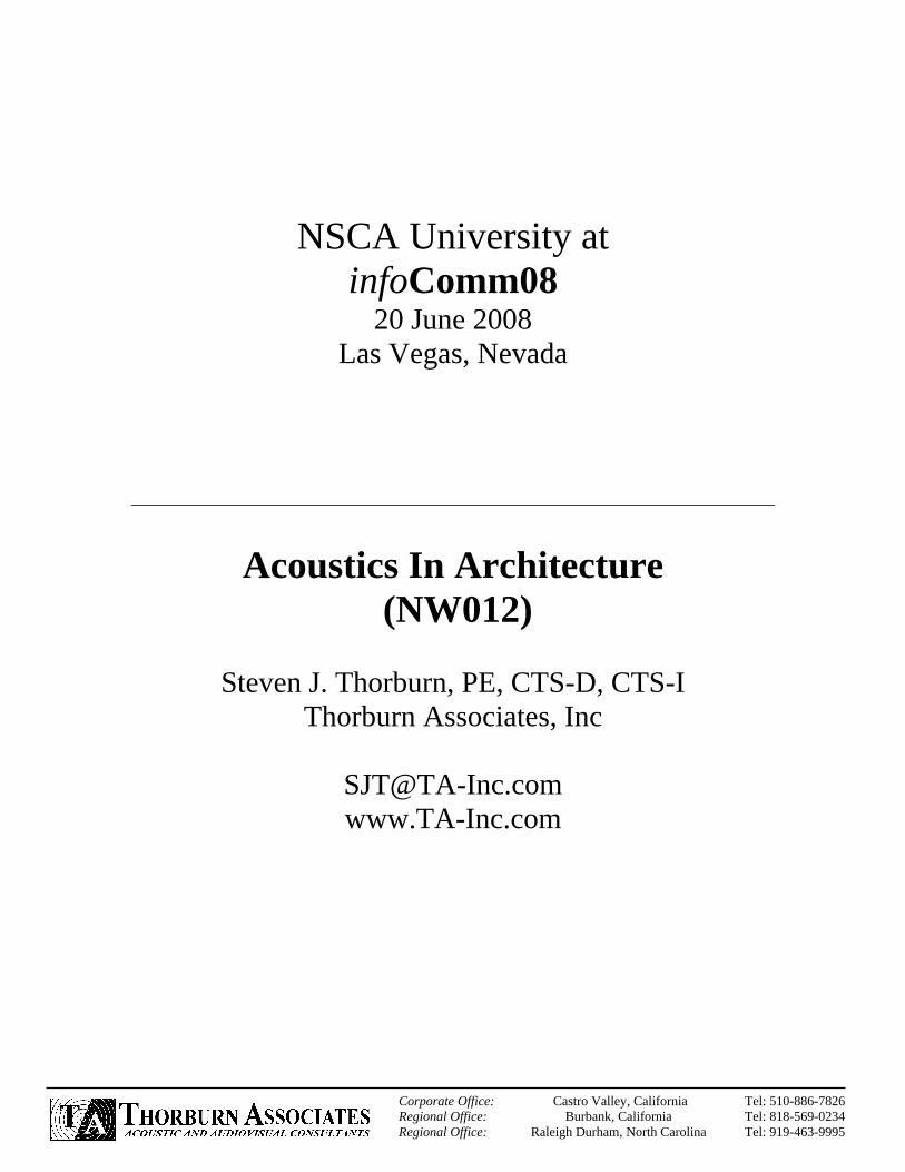
Narrow Band Data SO
UN
D P
RES
SUR
E LE
VEL,
dB
OCTAVE BAND CENTER FREQUENCIES, Hz
80
70
60
50
40
30
20
10
31 63 125 250 500 1K 2K 4K 8K
Slide 14 Acoustics In Architecture -- 2008
Octave Band (OB)Every time we double the frequency, we have an octave.To make acoustical analysis, sound was divided into bands.
Centered on:31.5, 63, 125, 250, 500, 1000,2000, 4000, 8000, 16000 Hz.
Slide 15 Acoustics In Architecture -- 2008
1/3 Octave BandThese bands can be further split down into other bands.1/3 octave are the most common.
63 Hz OB is made up of:50, 63, 80 Hz 1/3 OB

Acoustics In Architecture
Corporate Office: Castro Valley, California Tel: 510-886-7826Regional Office: Burbank, California Tel: 818-569-0234Regional Office: Raleigh-Durham, North Carolina Tel: 919-463-9995
TA Copyright 2008
Slide 16 Acoustics In Architecture -- 2008
Octave Band Data SO
UN
D P
RES
SUR
E LE
VEL,
dB
80
70
60
50
40
30
20
10
31 63 125 250 500 1K 2K 4K 8K
OCTAVE BAND CENTER FREQUENCIES, Hz
Slide 17 Acoustics In Architecture -- 2008
Weighting
FlatLoudnessdBAdBC
Slide 18 Acoustics In Architecture -- 2008
Acoustics 101
You Passed

Acoustics In Architecture
Corporate Office: Castro Valley, California Tel: 510-886-7826Regional Office: Burbank, California Tel: 818-569-0234Regional Office: Raleigh-Durham, North Carolina Tel: 919-463-9995
TA Copyright 2008
Slide 19 Acoustics In Architecture -- 2008
Board RoomSound IsolationRoom ModesRoom Acoustics
Slide 20 Acoustics In Architecture -- 2008
Sound IsolationSound Isolation – Keeping unwanted sound out of a room or keeping loud events in a room from impacting other spacesWallsFloor CeilingDoors / WindowsPenetrations
Slide 21 Acoustics In Architecture -- 2008
Sound Isolation Sound is blocked by partitions with mass.Sound can be blocked by two light weight partitions separated by a large air space.

Acoustics In Architecture
Corporate Office: Castro Valley, California Tel: 510-886-7826Regional Office: Burbank, California Tel: 818-569-0234Regional Office: Raleigh-Durham, North Carolina Tel: 919-463-9995
TA Copyright 2008
Slide 22 Acoustics In Architecture -- 2008
Sound Impinging on a Structure
Ii
Ir
ItIa
Slide 23 Acoustics In Architecture -- 2008
Sound IsolationSound Isolation – Sometimes called Noise Reduction or Noise Control
Source – How LoudPath - (what we are solving for)Receiver – How Quiet
Slide 24 Acoustics In Architecture -- 2008
Sound IsolationSource – How LoudFan or Mechanical Data – 1/1 Octave bandsTraffic Noise – broadband dBAOccupant noise - measure

Acoustics In Architecture
Corporate Office: Castro Valley, California Tel: 510-886-7826Regional Office: Burbank, California Tel: 818-569-0234Regional Office: Raleigh-Durham, North Carolina Tel: 919-463-9995
TA Copyright 2008
Slide 25 Acoustics In Architecture -- 2008
Sound IsolationHow Loud Should the Room Be –this is usually addressed in NC / PNC / RC – I use NC.More later on this for the Auditorium
Slide 26 Acoustics In Architecture -- 2008
Noise Criteria Curves (NC)
SOU
ND
PR
ESSU
RE
LEVE
L, d
B
OCTAVE BAND CENTER FREQUENCIES, Hz
80
70
60
50
40
30
20
10
31 63 125 250 500 1K 2K 4K 8K
NC-65NC-60NC-55NC-50NC-45NC-40NC-35NC-30
NC-25NC-20NC-15
Kitchens, Shops, Computer Rooms-- Moderately fair listening conditions
Concert Halls, Studios, Churches-- For excellent listening conditions
Auditoriums, Theatres, Conference Rooms-- For very good listening conditions
Private Offices, Classrooms, Libraries-- For good listening conditions
Large Offices, Reception Areas, Restaurants-- For moderately good listening conditions
Lobbies, Labs, Open Plan Offices-- For fair listening conditions
Slide 27 Acoustics In Architecture -- 2008
Sound IsolationSo what wall do we use:
Let’s assume we have a fan room next to the board room. The manufacturer tells us that the casing radiated noise levels are:
63 125 250 500 1K 2K 4K 8KSource (Fan) 78 80 76 68 62 54 46 42
1/1 Octave Band (Hz), Sound Levels (dB)

Acoustics In Architecture
Corporate Office: Castro Valley, California Tel: 510-886-7826Regional Office: Burbank, California Tel: 818-569-0234Regional Office: Raleigh-Durham, North Carolina Tel: 919-463-9995
TA Copyright 2008
Slide 28 Acoustics In Architecture -- 2008
Sound IsolationSource – Path = Receiver orSource – Receiver = Path Required
•Sound Power•Room Effect
63 125 250 500 1K 2K 4K 8KSource (Fan) 78 80 76 68 62 54 46 42Receive (NC-30) 57 48 41 35 31 29 28 27Difference S-R 21 32 35 33 31 25 18 15
1/1 Octave Band (Hz), Sound Levels (dB)
Slide 29 Acoustics In Architecture -- 2008
Room FactorWe could use:
Lp = sound-pressure level at a distance r from thesource, dB Re 2 x 10⁻⁵ N/m2
Lp = Lw + 10 Log10
a = room absorption, m2 (sabins)
+4a
Q4πr2( )
Lw = sound-power of the source, dB Re 10-12 W
r = distance from source, m
Q = source directivity in its proposed configuration
Slide 30 Acoustics In Architecture -- 2008
Transmission Loss (TL)A measurement of how much sound energy is reduced in transmission through materials.

Acoustics In Architecture
Corporate Office: Castro Valley, California Tel: 510-886-7826Regional Office: Burbank, California Tel: 818-569-0234Regional Office: Raleigh-Durham, North Carolina Tel: 919-463-9995
TA Copyright 2008
Slide 31 Acoustics In Architecture -- 2008
Sound IsolationHunt for walls with matching TL
•TL tests limited to 100 (Hz) 1/3 OB•TL tests limited to 4k (Hz) 1/3 OB•Use data referenced from a Lab!
63 125 250 500 1K 2K 4K 8KSource (Fan) 78 80 76 68 62 54 46 42Receive (NC-30) 57 48 41 35 31 29 28 27Difference S-R 21 32 35 33 31 25 18 15TL item 11 Appendix B-1
?? 32 42 54 53 54 52 ??
?? 0 7 21 22 29 34 ??
1/1 Octave Band (Hz), Sound Levels (dB)
Slide 32 Acoustics In Architecture -- 2008
Sound Transmission Class (STC)1/3 octave band transmission loss.Noise reduction corrected to standard room.
Slide 33 Acoustics In Architecture -- 2008
Sound Transmission Class (STC)
TL = Sound Transmission Lossof Barrier
A2 = Absorption in ReceivingRoom (Sabine)
S = Surface Area ofBarrier (ft2)
A2SNr = TL + 10 Log

Acoustics In Architecture
Corporate Office: Castro Valley, California Tel: 510-886-7826Regional Office: Burbank, California Tel: 818-569-0234Regional Office: Raleigh-Durham, North Carolina Tel: 919-463-9995
TA Copyright 2008
Slide 34 Acoustics In Architecture -- 2008
STC 45 Wall Detail
SECTION
PLANVIEW
SECTION
Gypsum Board (1 & 1)
Batt Insulation
Metal Stud
Seal Airtight
Seal Airtight
Slide 35 Acoustics In Architecture -- 2008
STC 50 Wall Section
Slide 36 Acoustics In Architecture -- 2008
STC 55 Wall Detail
SECTION
PLANVIEW
SECTION
Gypsum Board (2 & 2)
Batt Insulation
Metal Stud
Seal Airtight
Seal Airtight

Acoustics In Architecture
Corporate Office: Castro Valley, California Tel: 510-886-7826Regional Office: Burbank, California Tel: 818-569-0234Regional Office: Raleigh-Durham, North Carolina Tel: 919-463-9995
TA Copyright 2008
Slide 37 Acoustics In Architecture -- 2008
STC 65 Wall Detail
SECTION
PLANVIEW
SECTION
Gypsum Board (2 & 2)
Batt Insulation
Metal Stud
Seal Airtight
Seal Airtight
Airspace
Slide 38 Acoustics In Architecture -- 2008
Composite TLA chain is only as strong as its weakest link.
Slide 39 Acoustics In Architecture -- 2008
Transmission Loss -- 50 dBALL BRICK - COMPOSITE TL 50 dB
100 dB 50 dB

Acoustics In Architecture
Corporate Office: Castro Valley, California Tel: 510-886-7826Regional Office: Burbank, California Tel: 818-569-0234Regional Office: Raleigh-Durham, North Carolina Tel: 919-463-9995
TA Copyright 2008
Slide 40 Acoustics In Architecture -- 2008
Transmission Loss -- 29 dB1/8 GLASS - COMPOSITE TL 29 dB
100 dB 71 dB
Slide 41 Acoustics In Architecture -- 2008
Transmission Loss -- 26 dB1/4 GLASS - COMPOSITE TL 26 dB
100 dB 74 dB
Slide 42 Acoustics In Architecture -- 2008
Transmission Loss -- 23 dB1/2 GLASS - COMPOSITE TL 23 dB
100 dB 77 dB

Acoustics In Architecture
Corporate Office: Castro Valley, California Tel: 510-886-7826Regional Office: Burbank, California Tel: 818-569-0234Regional Office: Raleigh-Durham, North Carolina Tel: 919-463-9995
TA Copyright 2008
Slide 43 Acoustics In Architecture -- 2008
Transmission Loss -- 20 dBALL GLASS - COMPOSITE TL 20 dB
100 dB 80 dB
Slide 44 Acoustics In Architecture -- 2008
Composite TL
TL = Transmission Loss (dB)
S = Surface Area (ft2)
τ = Sound Transmission Coefficient
Composite TL = 10 Log ( )ΣSΣτS
Slide 45 Acoustics In Architecture -- 2008
Composite TL
Brick
TL = 10 Log 1τ
50 = 10 Log 1τ
5 = Log 1τ
= 10 51ττ = 10 -5
Glass
TL = 10 Log 1τ
20 = 10 Log 1τ
2 = Log 1τ
= 10 21ττ = 10 -2

Acoustics In Architecture
Corporate Office: Castro Valley, California Tel: 510-886-7826Regional Office: Burbank, California Tel: 818-569-0234Regional Office: Raleigh-Durham, North Carolina Tel: 919-463-9995
TA Copyright 2008
Slide 46 Acoustics In Architecture -- 2008
Composite TL
= 10 Log 100(10-5 x 87.5 + 10-2 x 12.5)
= 10 Log 100(12.6 x 10⁻² )
= 10 Log (800)
= 10 x 2.9031 = 29dB
Composite TL = 10 Log ( )ΣSΣτS
Slide 47 Acoustics In Architecture -- 2008
Leaks
Slide 48 Acoustics In Architecture -- 2008
Ducts

Acoustics In Architecture
Corporate Office: Castro Valley, California Tel: 510-886-7826Regional Office: Burbank, California Tel: 818-569-0234Regional Office: Raleigh-Durham, North Carolina Tel: 919-463-9995
TA Copyright 2008
Slide 49 Acoustics In Architecture -- 2008
Big Pipe
Slide 50 Acoustics In Architecture -- 2008
Outlet
Slide 51 Acoustics In Architecture -- 2008
Acoustical Doors and Windows

Acoustics In Architecture
Corporate Office: Castro Valley, California Tel: 510-886-7826Regional Office: Burbank, California Tel: 818-569-0234Regional Office: Raleigh-Durham, North Carolina Tel: 919-463-9995
TA Copyright 2008
Slide 52 Acoustics In Architecture -- 2008
Acoustical Doors
Jamb and Head
Floor
Solid CoreWood Door
Slide 53 Acoustics In Architecture -- 2008
Acoustical Doors
Slide 54 Acoustics In Architecture -- 2008

Acoustics In Architecture
Corporate Office: Castro Valley, California Tel: 510-886-7826Regional Office: Burbank, California Tel: 818-569-0234Regional Office: Raleigh-Durham, North Carolina Tel: 919-463-9995
TA Copyright 2008
Slide 55 Acoustics In Architecture -- 2008
Sound IsolationSo what wall do we use:
Let’s assume we do not want to have people hear what is going on inside the room as they eavesdrop in the hall!
63 125 250 500 1K 2K 4K 8KSource (Teleconference) 65 74 78 80 79 75 68 60
1/1 Octave Band (Hz), Sound Levels (dB)
Slide 56 Acoustics In Architecture -- 2008
Sound IsolationSource – Path = Receiver orSource – Receiver = Path Required
63 125 250 500 1K 2K 4K 8KSource (Teleconference) 65 74 78 80 79 75 68 60Receive (NC40) 64 57 50 45 41 39 38 37Difference S-R 1 17 28 35 38 36 30 23
1/1 Octave Band (Hz), Sound Levels (dB)
Slide 57 Acoustics In Architecture -- 2008
Boardroom Room AcousticsBoardrooms are really too small for Reverberation Time Calculations (diffuse field)Goals
Even Room ModesMixing Up Finishes

Acoustics In Architecture
Corporate Office: Castro Valley, California Tel: 510-886-7826Regional Office: Burbank, California Tel: 818-569-0234Regional Office: Raleigh-Durham, North Carolina Tel: 919-463-9995
TA Copyright 2008
Slide 58 Acoustics In Architecture -- 2008
Reverberation FieldWhere the room (building space) limits the fall off of sound.
i.e. Sound levels stop falling off by 6 db every time the distance is doubled.
As more sound-absorbing treatment is used, the reduction of sound level with distance becomes more like the reduction outdoors, but there is a point of diminishing returns.
Slide 59 Acoustics In Architecture -- 2008
Sound Fields
Free FieldNear Field
ReverberantField
6 dB per Doubling ofDistanceL
(d
B)
p
Log (Distance)
Slide 60 Acoustics In Architecture -- 2008
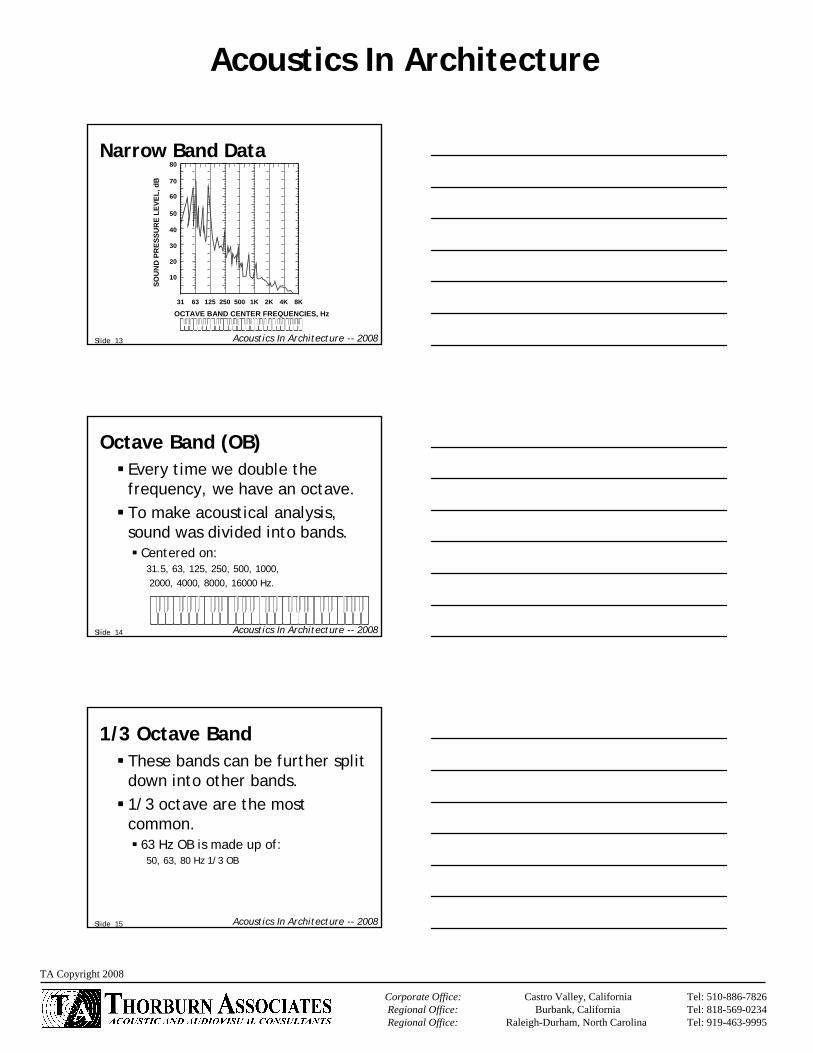
What Is a Room Mode?A standing wave The wave length is evenly divisible by the room’s dimensionsLow Frequency Issue (< 400 Hz)
Acoustics In Architecture
Corporate Office: Castro Valley, California Tel: 510-886-7826Regional Office: Burbank, California Tel: 818-569-0234Regional Office: Raleigh-Durham, North Carolina Tel: 919-463-9995
TA Copyright 2008
Slide 61 Acoustics In Architecture -- 2008
Standing-Wave PatternRope
Node Antinode
Slide 62 Acoustics In Architecture -- 2008
Standing-Wave PatternAir
Node Antinode
back
Slide 63 Acoustics In Architecture -- 2008
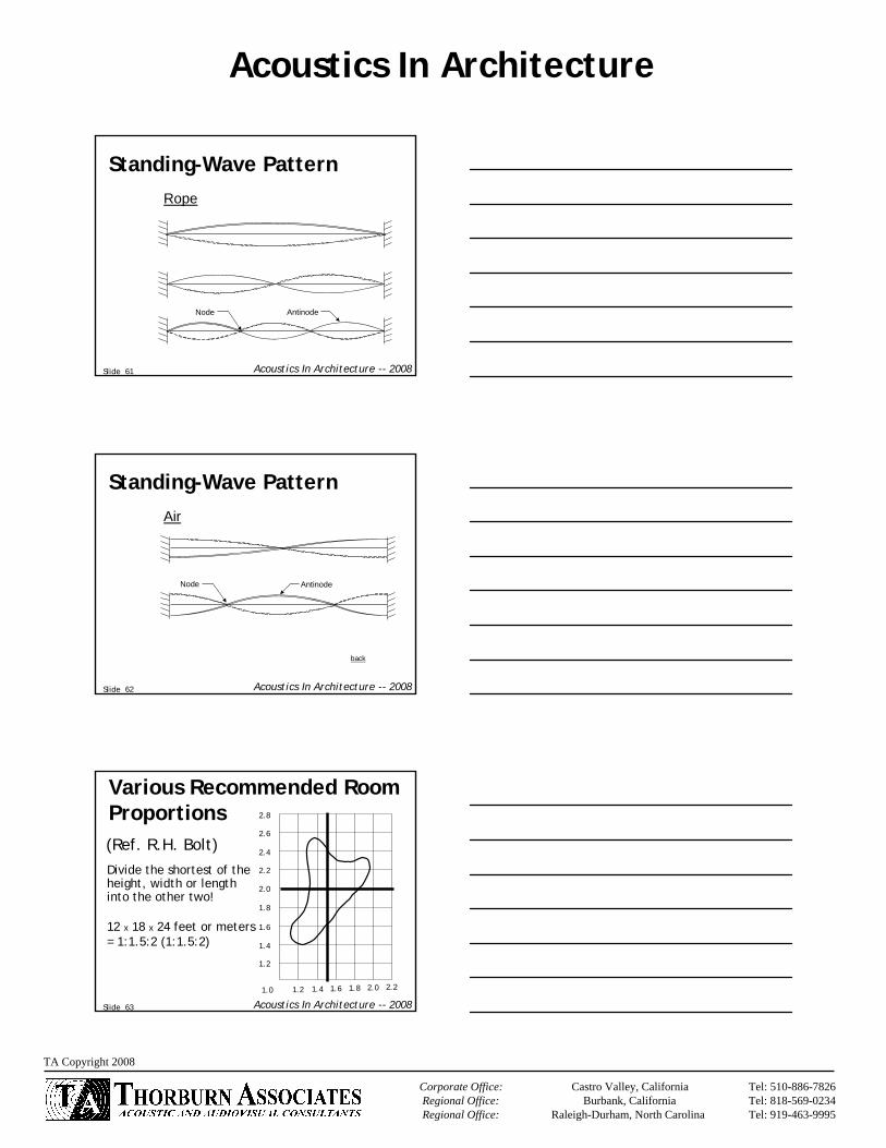
Various Recommended Room Proportions(Ref. R.H. Bolt)
2.8
2.6
2.4
2.2
2.0
1.8
1.6
1.4
1.2
1.0 1.2 1.4 1.6 1.8 2.0 2.2
Divide the shortest of the height, width or length into the other two!
12 x 18 x 24 feet or meters= 1:1.5:2 (1:1.5:2)
Acoustics In Architecture
Corporate Office: Castro Valley, California Tel: 510-886-7826Regional Office: Burbank, California Tel: 818-569-0234Regional Office: Raleigh-Durham, North Carolina Tel: 919-463-9995
TA Copyright 2008
Slide 64 Acoustics In Architecture -- 2008
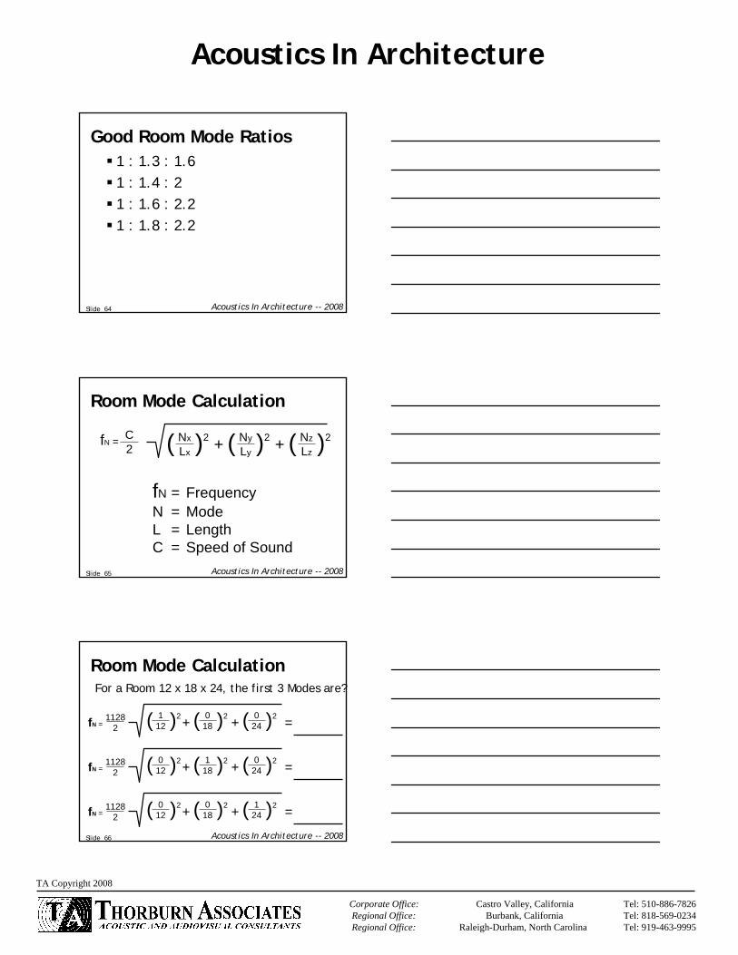
Good Room Mode Ratios1 : 1.3 : 1.61 : 1.4 : 21 : 1.6 : 2.21 : 1.8 : 2.2
Slide 65 Acoustics In Architecture -- 2008
( )2( )2
Room Mode Calculation
fN = C2
NxLx( )2 + Ny
Ly + NzLz
fN = FrequencyN = ModeL = LengthC = Speed of Sound
Slide 66 Acoustics In Architecture -- 2008
( )2 ( )2( )2
Room Mode Calculation
fN =1128
2012 + 0
18 + 124 =
( )2 ( )2( )2fN =1128
2012 + 1
18 + 024 =
( )2 ( )2( )2fN =1128
2112 + 0
18 + 024 =
For a Room 12 x 18 x 24, the first 3 Modes are?

Acoustics In Architecture
Corporate Office: Castro Valley, California Tel: 510-886-7826Regional Office: Burbank, California Tel: 818-569-0234Regional Office: Raleigh-Durham, North Carolina Tel: 919-463-9995
TA Copyright 2008
Slide 67 Acoustics In Architecture -- 2008
Types Of Room ModesAxial – Two SurfacesTangential – Four SurfacesOblique – Six Surfaces
Slide 68 Acoustics In Architecture -- 2008
Schroeder Cutoff Frequencyis the frequency above which the standing waves are that closely spaced that they do not substantially affect the sound, it is the frequency above which there are more than three modal frequencies within the bandwidth (1/3 octave band) of every mode. It depends on Volume and Reverberation Time which influences the bandwidth of the modal frequencies. The larger the room or the shorter the reverberation time the lower the Schroeder frequency.A lower Schroeder frequency will cause the frequency to smooth over a wider frequency range.
Slide 69 Acoustics In Architecture -- 2008
Board Room – Room AcousticsGenerally not an issueTreat one wall (>150 sf) with 1 to 2 inch thick sound absorbing panelsTreat two walls (>250 sf)Chair Rail To CeilingAt Least 50% of Ceiling ATCTo Small for RT60 (>10,000 c.f. start doing RT60 cals)

Acoustics In Architecture
Corporate Office: Castro Valley, California Tel: 510-886-7826Regional Office: Burbank, California Tel: 818-569-0234Regional Office: Raleigh-Durham, North Carolina Tel: 919-463-9995
TA Copyright 2008
Slide 70 Acoustics In Architecture -- 2008
Questions and Answers
Slide 71 Acoustics In Architecture -- 2008
Mechanical Noise ControlRoom AcousticsReverberation Time
Slide 72 Acoustics In Architecture -- 2008
Things to Avoid in Large Room Design
EchoesFlutter EchoesSound FocusingSound ShadowsExcessive ReverberationBackground Noise

Acoustics In Architecture
Corporate Office: Castro Valley, California Tel: 510-886-7826Regional Office: Burbank, California Tel: 818-569-0234Regional Office: Raleigh-Durham, North Carolina Tel: 919-463-9995
TA Copyright 2008
Slide 73 Acoustics In Architecture -- 2008
EchoesStrong refection well above reverberant decay. We can start to hear echoes at 35 milliseconds. (Haus effect)
0
Sou
nd P
ress
ure
t
Echo
Possible Echo
Slide 74 Acoustics In Architecture -- 2008
Flutter EchoesA series of echoes between parallel surfaces
SOURCE
Slide 75 Acoustics In Architecture -- 2008
Sound FocusingEffects of curved surfaces
S
S1

Acoustics In Architecture
Corporate Office: Castro Valley, California Tel: 510-886-7826Regional Office: Burbank, California Tel: 818-569-0234Regional Office: Raleigh-Durham, North Carolina Tel: 919-463-9995
TA Copyright 2008
Slide 76 Acoustics In Architecture -- 2008
Sound ShadowsSeats that do not have full exposure to the reverberant field, such as under balconies, or in wing areas of asymmetric meeting rooms.
Slide 77 Acoustics In Architecture -- 2008
Excessive ReverberationToo much acoustical energy will cause muddiness and affect speech intelligibility.
Slide 78 Acoustics In Architecture -- 2008
Background NoiseLet’s make it so quiet we can hear a pin drop.

Acoustics In Architecture
Corporate Office: Castro Valley, California Tel: 510-886-7826Regional Office: Burbank, California Tel: 818-569-0234Regional Office: Raleigh-Durham, North Carolina Tel: 919-463-9995
TA Copyright 2008
Slide 79 Acoustics In Architecture -- 2008
Background NoiseNC -- Noise Criteria is a family of curves established in 1957.The amount of noise that a mechanical system makes in a room.Equal loudness curves which take into account that we do not perceive the magnitude of the low frequency noise levels.
Slide 80 Acoustics In Architecture -- 2008
Noise Criteria Curves (NC)
SOU
ND
PR
ESSU
RE
LEVE
L, d
B
OCTAVE BAND CENTER FREQUENCIES, Hz
80
70
60
50
40
30
20
10
31 63 125 250 500 1K 2K 4K 8K
NC-65NC-60NC-55NC-50NC-45NC-40NC-35NC-30
NC-25NC-20NC-15
Kitchens, Shops, Computer Rooms-- Moderately fair listening conditions
Concert Halls, Studios, Churches-- For excellent listening conditions
Auditoriums, Theatres, Conference Rooms-- For very good listening conditions
Private Offices, Classrooms, Libraries-- For good listening conditions
Large Offices, Reception Areas, Restaurants-- For moderately good listening conditions
Lobbies, Labs, Open Plan Offices-- For fair listening conditions
Slide 81 Acoustics In Architecture -- 2008
Noise Criteria Chart
Extremely Noisy
Very Noisy
Moderately Noisyto Noisy
Very Quietto QuietSO
UN
D P
RES
SUR
E LE
VEL,
dB
80
70
60
50
40
30
20
10
31 63 125 250 500 1K 2K 4K 8KOCTAVE BAND CENTER FREQUENCIES, Hz
NC-65NC-60NC-55NC-50NC-45NC-40NC-35NC-30NC-25NC-20NC-15

Acoustics In Architecture
Corporate Office: Castro Valley, California Tel: 510-886-7826Regional Office: Burbank, California Tel: 818-569-0234Regional Office: Raleigh-Durham, North Carolina Tel: 919-463-9995
TA Copyright 2008
Slide 82 Acoustics In Architecture -- 2008
Fan LocationAlways over your roomYou want it as far away as possible
Slide 83 Acoustics In Architecture -- 2008
Duct SystemSupply ReturnLined SilencersDiffusers
Slide 84 Acoustics In Architecture -- 2008

Acoustics In Architecture
Corporate Office: Castro Valley, California Tel: 510-886-7826Regional Office: Burbank, California Tel: 818-569-0234Regional Office: Raleigh-Durham, North Carolina Tel: 919-463-9995
TA Copyright 2008
Slide 85 Acoustics In Architecture -- 2008
Slide 86 Acoustics In Architecture -- 2008
Slide 87 Acoustics In Architecture -- 2008
Roof Top Fan SystemsFan
Return Silencer Diffuser
SupplyDuct
ControlUnit

Acoustics In Architecture
Corporate Office: Castro Valley, California Tel: 510-886-7826Regional Office: Burbank, California Tel: 818-569-0234Regional Office: Raleigh-Durham, North Carolina Tel: 919-463-9995
TA Copyright 2008
Slide 88 Acoustics In Architecture -- 2008
HVAC Noise Control
Fan
Split
Diffuser
Slide 89 Acoustics In Architecture -- 2008
Slide 90 Acoustics In Architecture -- 2008
HVAC Noise Control
Fan
Split
Diffuser
Silencer

Acoustics In Architecture
Corporate Office: Castro Valley, California Tel: 510-886-7826Regional Office: Burbank, California Tel: 818-569-0234Regional Office: Raleigh-Durham, North Carolina Tel: 919-463-9995
TA Copyright 2008
Slide 91 Acoustics In Architecture -- 2008
Ducts
Dampers
Main Duct
Branch Duct
Diffuser
SecondaryBranchDuct
Slide 92 Acoustics In Architecture -- 2008
Vibration IsolationAIRBORNESOUND
Rigid Base
VibrationIsolators
Transmitted Noise andVibration is Reduced
EquipmentNear Columns
Slide 93 Acoustics In Architecture -- 2008
Vibration Isolation

Acoustics In Architecture
Corporate Office: Castro Valley, California Tel: 510-886-7826Regional Office: Burbank, California Tel: 818-569-0234Regional Office: Raleigh-Durham, North Carolina Tel: 919-463-9995
TA Copyright 2008
Slide 94 Acoustics In Architecture -- 2008
Vibration Isolation
Slide 95 Acoustics In Architecture -- 2008
Plumbing Isolation
Slide 96 Acoustics In Architecture -- 2008
Plumbing Isolation

Acoustics In Architecture
Corporate Office: Castro Valley, California Tel: 510-886-7826Regional Office: Burbank, California Tel: 818-569-0234Regional Office: Raleigh-Durham, North Carolina Tel: 919-463-9995
TA Copyright 2008
Slide 97 Acoustics In Architecture -- 2008
Plumbing Isolation
Slide 98 Acoustics In Architecture -- 2008
Electrical Isolation
Slide 99 Acoustics In Architecture -- 2008
Room Acoustics
AbsorptionReverberation
Reflections

Acoustics In Architecture
Corporate Office: Castro Valley, California Tel: 510-886-7826Regional Office: Burbank, California Tel: 818-569-0234Regional Office: Raleigh-Durham, North Carolina Tel: 919-463-9995
TA Copyright 2008
Slide 100 Acoustics In Architecture -- 2008
AbsorptionNRC -- Noise Reduction CoefficientThe mathematical average of the absorption coefficient of the 250, 500, 1000, and 2000 Hz octave bands.Has nothing to do with noise reduction.
Slide 101 Acoustics In Architecture -- 2008
ABSORPTION -- NRC
NRC 1.00
Totally Absorptive
Slide 102 Acoustics In Architecture -- 2008
ABSORPTION -- NRC
NRC 1.00
Totally Absorptive
NRC 0.00
Totally Reflective

Acoustics In Architecture
Corporate Office: Castro Valley, California Tel: 510-886-7826Regional Office: Burbank, California Tel: 818-569-0234Regional Office: Raleigh-Durham, North Carolina Tel: 919-463-9995
TA Copyright 2008
Slide 103 Acoustics In Architecture -- 2008
Effect of the Mounting Condition
1.00.90.80.70.60.50.40.30.20.10.0
125 250 500 1K 2K 4K NRC
Slide 104 Acoustics In Architecture -- 2008
1.00.90.80.70.60.50.40.30.20.10.0
125 250 500 1K 2K 4K NRC
Effect of the Mounting Condition
Slide 105 Acoustics In Architecture -- 2008
ASTM Mounting Conditions

Acoustics In Architecture
Corporate Office: Castro Valley, California Tel: 510-886-7826Regional Office: Burbank, California Tel: 818-569-0234Regional Office: Raleigh-Durham, North Carolina Tel: 919-463-9995
TA Copyright 2008
Slide 106 Acoustics In Architecture -- 2008
ASTM Mounting Conditions
Slide 107 Acoustics In Architecture -- 2008
Effects of Mounting Conditions on Absorption
Slide 108 Acoustics In Architecture -- 2008
Effects of Mounting Conditions on Absorption
Slide 62/63

Acoustics In Architecture
Corporate Office: Castro Valley, California Tel: 510-886-7826Regional Office: Burbank, California Tel: 818-569-0234Regional Office: Raleigh-Durham, North Carolina Tel: 919-463-9995
TA Copyright 2008
Slide 109 Acoustics In Architecture -- 2008
Effects of Mounting Conditions on Absorption
Slide 110 Acoustics In Architecture -- 2008
Effects of Mounting Conditions on Absorption
Slide 111 Acoustics In Architecture -- 2008
Wave LengthWavelength =
Speed of sound 1128 ft/s (343 m/s)Frequency (cycles per second)
Wavelength’s notation is λλ = Lambda
FrequencySpeed of Sound

Acoustics In Architecture
Corporate Office: Castro Valley, California Tel: 510-886-7826Regional Office: Burbank, California Tel: 818-569-0234Regional Office: Raleigh-Durham, North Carolina Tel: 919-463-9995
TA Copyright 2008
Slide 112 Acoustics In Architecture -- 2008
Slide 113 Acoustics In Architecture -- 2008
NRC CalculationHeavy Carpet
250 = 0.06500 = 0.14
1000 = 0.372000 = 0.60NRC = 0.30
Slide 114 Acoustics In Architecture -- 2008
NRC CalculationLow Frequency Absorption
250 = 0.90500 = 0.80
1000 = 0.502000 = 0.40NRC = 0.65

Acoustics In Architecture
Corporate Office: Castro Valley, California Tel: 510-886-7826Regional Office: Burbank, California Tel: 818-569-0234Regional Office: Raleigh-Durham, North Carolina Tel: 919-463-9995
TA Copyright 2008
Slide 115 Acoustics In Architecture -- 2008
ReverberationNRC AbsorptionTypes of MaterialsMounting of MaterialsLocation
Slide 116 Acoustics In Architecture -- 2008
Suggested Reverberation Times
0.2 0.4 0.6 0.8 1.0 1.2 1.4 1.6 1.8 2.0 2.2 2.4 2.6
Recording and broadcasting studio
Elementary classrooms
Intimate drama
Lecture and conference rooms
Cinema
Small theaters
High school auditorium
Multipurpose auditoriums
Churches Cathedrals
Semi-classical concerts,chorus,(using sounds system)
Symphonic (classical to romantic)
Reverberation time (sec)
‘Live’ spaces (sound persists)‘Dead’ spaces (sound decays rapidly)
SPEE
CHSP
EECH
& M
USI
CM
USI
C
Slide 117 Acoustics In Architecture -- 2008
Reflected Sound in aTreated Room
Reverberation
time
60 dB

Acoustics In Architecture
Corporate Office: Castro Valley, California Tel: 510-886-7826Regional Office: Burbank, California Tel: 818-569-0234Regional Office: Raleigh-Durham, North Carolina Tel: 919-463-9995
TA Copyright 2008
Slide 118 Acoustics In Architecture -- 2008
Reflected Sound in aTreated Room
Reverberation
time
60 dB
Slide 119 Acoustics In Architecture -- 2008
Reflected Sound in aTreated Room
Reverberation
time
60 dB
Slide 120 Acoustics In Architecture -- 2008
Reflected Sound in aTreated Room
Reverberation
time
60 dB

Acoustics In Architecture
Corporate Office: Castro Valley, California Tel: 510-886-7826Regional Office: Burbank, California Tel: 818-569-0234Regional Office: Raleigh-Durham, North Carolina Tel: 919-463-9995
TA Copyright 2008
Slide 121 Acoustics In Architecture -- 2008
RT 60 Equation
Where: T = reverberation time required for sound todecay 60 dB after the source has stopped (s)
V = room volume (ft3)a = total ft2 of room absorption (sabins, so
named to honor W.C. Sabine)
It should not be used for recording studios or anechoic chambers,which have extremely high ratios of absorption to room volume.In these cases, the Eyring formula should be used.
T = 0.049 Va
Slide 122 Acoustics In Architecture -- 2008
RT 60 CalculationCompute the surface areas S.
S = 60 x 35 = 2100 ft2S = 2 x 35 x 15 = 1050 ft2S = 2 x 60 x 15 = 1800 ft2S = 60 x 35 = 2100 ft2
ceilingwalls
floor
Slide 123 Acoustics In Architecture -- 2008
RT 60 CalculationCompute the total room absorption a using a =SSa.
2100 x 0.04 = 842850 x 0.30 = 8552100 x 0.10 = 210
ceilingwallsfloor
S α a (sabins)
Total a = 1149 sabins

Acoustics In Architecture
Corporate Office: Castro Valley, California Tel: 510-886-7826Regional Office: Burbank, California Tel: 818-569-0234Regional Office: Raleigh-Durham, North Carolina Tel: 919-463-9995
TA Copyright 2008
Slide 124 Acoustics In Architecture -- 2008
Let’s Do an RT60 Calc!
Slide 125 Acoustics In Architecture -- 2008
RT60 Goal – 0.8 to 1.0 Seconds (slide 119)
Slide 126 Acoustics In Architecture -- 2008
Floor Plan
675 1575 335 310Total Square Feet: 2895

Acoustics In Architecture
Corporate Office: Castro Valley, California Tel: 510-886-7826Regional Office: Burbank, California Tel: 818-569-0234Regional Office: Raleigh-Durham, North Carolina Tel: 919-463-9995
TA Copyright 2008
Slide 127 Acoustics In Architecture -- 2008
Ceiling Plan
3152585
Slide 128 Acoustics In Architecture -- 2008
West Elevation
320 760
Slide 129 Acoustics In Architecture -- 2008
East Elevation
480

Acoustics In Architecture
Corporate Office: Castro Valley, California Tel: 510-886-7826Regional Office: Burbank, California Tel: 818-569-0234Regional Office: Raleigh-Durham, North Carolina Tel: 919-463-9995
TA Copyright 2008
Slide 130 Acoustics In Architecture -- 2008
North Elevation
725350265
Slide 131 Acoustics In Architecture -- 2008
South Elevation
494744
Slide 132 Acoustics In Architecture -- 2008
Mixing Acoustical Finishes

Acoustics In Architecture
Corporate Office: Castro Valley, California Tel: 510-886-7826Regional Office: Burbank, California Tel: 818-569-0234Regional Office: Raleigh-Durham, North Carolina Tel: 919-463-9995
TA Copyright 2008
Slide 133 Acoustics In Architecture -- 2008
Direct, Early, and Reverberant Sound
Direct
First Reflection
Slide 134 Acoustics In Architecture -- 2008
Direct, Early, and Reverberant Sound
Impulse
Direct Sound
First Reflection
EarlySound
0
Sou
nd P
ress
ure t0
t1
t2
t
Slide 135 Acoustics In Architecture -- 2008
ReflectionsReflective surface will absorb no wave energyReturns all energy back to the space it came fromReflective acoustic surface: concrete wall

Acoustics In Architecture
Corporate Office: Castro Valley, California Tel: 510-886-7826Regional Office: Burbank, California Tel: 818-569-0234Regional Office: Raleigh-Durham, North Carolina Tel: 919-463-9995
TA Copyright 2008
Slide 136 Acoustics In Architecture -- 2008
Reflection
Slide 137 Acoustics In Architecture -- 2008
Reflection ( x > 4 λ )x > 4 λ
Flat sound-reflectingpanel
ir
Reflected sound path
Slide 138 Acoustics In Architecture -- 2008
Reflection of Sound
Flat Surface acts like a mirror.
S

Acoustics In Architecture
Corporate Office: Castro Valley, California Tel: 510-886-7826Regional Office: Burbank, California Tel: 818-569-0234Regional Office: Raleigh-Durham, North Carolina Tel: 919-463-9995
TA Copyright 2008
Slide 139 Acoustics In Architecture -- 2008
Reflection of Sound
S
S1
Concave Surface concentrates sound in the region S .1
Slide 140 Acoustics In Architecture -- 2008
Reflection of Sound
S
Convex Surface scatters sound.
Slide 141 Acoustics In Architecture -- 2008
AbsorptionConversion of sound energy to heatCommon acoustically absorptive material: fiberglass insulation

Acoustics In Architecture
Corporate Office: Castro Valley, California Tel: 510-886-7826Regional Office: Burbank, California Tel: 818-569-0234Regional Office: Raleigh-Durham, North Carolina Tel: 919-463-9995
TA Copyright 2008
Slide 142 Acoustics In Architecture -- 2008
Absorption
Slide 143 Acoustics In Architecture -- 2008
DiffusionCombination of sound wavesIncreases distribution of the direction of soundDiffused sound energy is distributed in time
Slide 144 Acoustics In Architecture -- 2008
Diffusion

Acoustics In Architecture
Corporate Office: Castro Valley, California Tel: 510-886-7826Regional Office: Burbank, California Tel: 818-569-0234Regional Office: Raleigh-Durham, North Carolina Tel: 919-463-9995
TA Copyright 2008
Slide 145 Acoustics In Architecture -- 2008
Diffusion ( x = λ )
Diffusedsound paths
Diffusing panel (typical lengthand width surface dimensionsare 3 ft to 10 ft with randomdepths (x) of 6 in to 2 ft)x = λ
Slide 146 Acoustics In Architecture -- 2008
Reflection of Sound
S
Rough Surface leads to diffuse reflection.
Slide 147 Acoustics In Architecture -- 2008
Questions and Answers

Acoustics In Architecture
Corporate Office: Castro Valley, California Tel: 510-886-7826Regional Office: Burbank, California Tel: 818-569-0234Regional Office: Raleigh-Durham, North Carolina Tel: 919-463-9995
TA Copyright 2008
Slide 148 Acoustics In Architecture -- 2008
Slide 149 Acoustics In Architecture -- 2008
Thank You!Acoustics In Architecture
Download Handout (10 Meg) atwww.TA-Inc.com/nsca.htm
[email protected] J. Thorburn PE, CTS-D, CTS-I
Thorburn Associates, Inc.San Francisco, California
Raleigh Durham, North CarolinaLos Angeles, California

COPYRIGHT 2004CTel: 919-463-9995Tel: 818-569-0234Tel: 510-886-7826Castro Valley, California
Burbank, CaliforniaMorrisville, North Carolina
Corporate Office:Regional Office:Regional Office:
FAN

`
Appendix A-7
Corporate Office: Regional Office: Regional Office
Castro Valley, California Burbank, California
Raleigh-Durham, North Carolina
Tel: 510-886-7826Tel: 818-569-0234Tel: 919-463-9995

`
Appendix A-7
Corporate Office: Regional Office: Regional Office
Castro Valley, California Burbank, California
Raleigh-Durham, North Carolina
Tel: 510-886-7826Tel: 818-569-0234Tel: 919-463-9995

`
Appendix A-13
Corporate Office: Regional Office: Regional Office
Castro Valley, California Burbank, California
Raleigh-Durham, North Carolina
Tel: 510-886-7826Tel: 818-569-0234Tel: 919-463-9995

`
Appendix A-13
Corporate Office: Regional Office: Regional Office
Castro Valley, California Burbank, California
Raleigh-Durham, North Carolina
Tel: 510-886-7826Tel: 818-569-0234Tel: 919-463-9995

`
Appendix A-20
Corporate Office: Regional Office: Regional Office
Castro Valley, California Burbank, California
Raleigh-Durham, North Carolina
Tel: 510-886-7826Tel: 818-569-0234Tel: 919-463-9995

`
Appendix A-20
Corporate Office: Regional Office: Regional Office
Castro Valley, California Burbank, California
Raleigh-Durham, North Carolina
Tel: 510-886-7826Tel: 818-569-0234Tel: 919-463-9995

`
Appendix A-26
Corporate Office: Regional Office: Regional Office
Castro Valley, California Burbank, California
Raleigh-Durham, North Carolina
Tel: 510-886-7826Tel: 818-569-0234Tel: 919-463-9995
8000
4000
2000
1000
500
250
125
1/
1 O
CT
AV
E B
AN
D A
BS
OR
PT
ION
63
8000
4000
2000
1000
500
250
125
1/
1 O
CT
AV
E B
AN
D A
BS
OR
PT
ION
63
MA
TE
RIA
L
TO
TA
L A
BS
OR
PT
ION
AV
G. A
BS
OR
PT
ION
RT
60 -
- S
AB
INE
AR
EA
ft^
2
Pro
ject
Nam
e:
Ru
n D
escr
ipti
on
:
Ro
om
Vo
lum
e (f
t^3)
SU
RF
AC
E

`
Appendix B-1
Corporate Office: Regional Office: Regional Office
Castro Valley, California Burbank, California
Raleigh-Durham, North Carolina
Tel: 510-886-7826Tel: 818-569-0234Tel: 919-463-9995
TRANSMISSION LOSS DATA FOR COMMON BUILDING ELEMENTS Transmission Loss (dB) STC IIC
Building Construction 125Hz 250Hz 500Hz 1000Hz 2000Hz 4000Hz Rating Rating* Walls 2-6'** Monolithic 1. 3/8-in plywood (1 lb/ft2) 14 18 22 20 21 26 22 2. 26-gauge sheet metal 12 14 15 21 21 25 20 (1.5 lb/ft2) 3. 1/2-in gypsum board 15 20 25 31 33 27 28 (2 lb/ft2) 4. 2 layers ½” gypsum board, 19 26 30 32 29 37 31 laminated w/ joint compound (4 lb/ft2) 5. 1 /32-in sheet lead (2 lb/ft2) 15 21 27 33 39 45 31 6. Glass-fiber roof fabric 6 9 11 16 20 25 16 (37.5 oz/yd2) Interior: 7. 2 by 4 wood studs 16 in oc with 17 31 33 40 38 36 33 ½” gypsum board both sides (5 lb/ft') 8. Construction no. 7 with 2-in glass 15 30 34 44 46 41 37 fiber insulation in cavity 9. 2 by 4 staggered wood studs 16 in 23 28 39 46 54 44 39 oc each side with 1/2-in gypsum board both sides (B lb/fl2) 10.Construction no. 9 with 2 1 /4-in 29 38 45 52 58 50 48 glass fiber insulation in cavity 11.2 by 4 wood studs 16 in oc with 32 42 52 58 53 54 52 5/8-ingypsum board both sides, one side screwed to resilient channels. 3-in glass-fiber insulation in cavity ( 7 lb/fi2) 12.Double row of 2 by 4 wood studs 31 44 55 62 67 65 54 16 in oc with 3/8-in gypsum board on both sides of construction. 9-in glass-fiber insulation in cavity (4 lb/ft2) 13. 6-in dense concrete block, 3 cells, 37 36 42 49 55 58 45 painted (34 lb/fi2) 14.8-in lightweight concrete block, 34 40 44 49 59 64 49 3 cells, painted (38 lb/ft2) 15.Construction no, 14 with expanded 34 40 46 52 60 66 51 mineral loose fill in cells 16.6-in lightweight concrete block with 35 42 50 64 67 65 53 1/2-in gypsum board supported by resilient metal channels on one side, other side painted (26 lb/ft2)

`
Appendix B-2
Corporate Office: Regional Office: Regional Office
Castro Valley, California Burbank, California
Raleigh-Durham, North Carolina
Tel: 510-886-7826Tel: 818-569-0234Tel: 919-463-9995
Transmission Loss (dB) STC IIC
Building Construction 125Hz 250Hz 500Hz 1000Hz 2000Hz 4000Hz Rating Rating 17.2 1/2-in steel channel studs 24 in 22 27 43 47 37 46 39 oc with 5/8-in gypsum board both sides (6 lb/ft2) 18.Construction no. 17 with 2-in 26 41 52 54 45 51 45 glass-fiber insulation in cavity 19.3 5/8-in steel channel studs 16 in 26 36 43 51 48 43 43 oc with 1/2-in gypsum board both sides (5 lb/fi2) 20.Construction no.19 with 3-in 28 45 54 55 47 54 48 mineral fiber insulation in cavity 21.2 1/2-in steel channel studs 24 in 28 31 46 51 53 47 44 oc with two layers 5/8-in gypsum board one side, one layer other side (8 lb/ft2) 22.Construction no. 21 with 2-in glass 31 43 55 58 61 51 51 fiber insulation in cavity 23. 3 5/8-in steel channel studs 24 in 34 41 51 54 46 52 48 oc with two layers 5/8-in gypsum board both sides ( 1 1 lb/ft2) 24.Construction no. 23 with 3-in 38 52 59 60 56 62 57 mineral fiber insulation in cavity Exterior: 25. 4 1 /2-in face brick (50 lb/ft2) 32 34 40 47 55 61 45 26.Two wythes of 4 1 / 2-in face brick 37 37 47 55 62 67 50 2-in airspace with metal ties (100 lb/fl2) 27.Two wythes of plastered 4 1/2-in 43 50 52 61 73 78 59 brick, 2-in airspace with giass-fiber insulation in cavity 28.2 by 4 wood studs 16 in oc with 1” 21 33 41 46 47 51 42 stucco on metal lath on outside and 1/2-in gypsum board on inside (8 lb/ft2) 29.6-in solid concrete with 1 / 2-in 39 42 50 58 64 67 53 plaster both sides (80 lb/ft2) Floor-Ceilings'2.3 30. 2 by 10 wood joists 16 in oc with 23 32 36 45 49 56 37 32 1/2- in plywood subfloor under 25/32-in oak on floor side, and 5/8-in gypsum board nailed to joists on ceiling side ( 10 lb / ft2) 31.Construction no. 30 with 5/8-in 30 35 44 50 54 60 47 gypsum board screwed to resilient channels spaced 24 in oc perpendicular to joists
`
Appendix B-3
Corporate Office: Regional Office: Regional Office
Castro Valley, California Burbank, California
Raleigh-Durham, North Carolina
Tel: 510-886-7826Tel: 818-569-0234Tel: 919-463-9995
Transmission Loss (dB) STC IIC
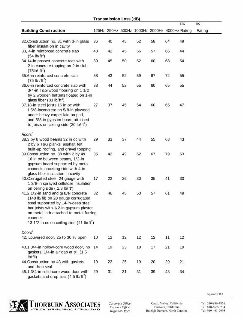
Building Construction 125Hz 250Hz 500Hz 1000Hz 2000Hz 4000Hz Rating Rating 32.Construction no. 31 with 3-in glass 36 40 45 52 58 64 49 fiber insulation in cavity 33, 4-in reinforced concrete slab 48 42 45 56 57 66 44 (54 lb/ft2) 34.14-in precast concrete tees with 39 45 50 52 60 68 54 2-in concrete topping on 2-in slab (75lb/ ft2) 35.6-in reinforced concrete slab 38 43 52 59 67 72 55 (75 lb /ft2) 36.6-in reinforced concrete slab with 38 44 52 55 60 65 55 3/4-in T&G wood flooring on 1 1/2 by 2 wooden battens floated on 1-in glass fiber (83 lb/ft2) 37.18-in steel joists 16 in oc with 27 37 45 54 60 65 47 I 5/8-inconcrete on 5/8-in plywood under heavy carpet laid on pad, and 5/8-in gypsum board attached to joists on ceiling side (20 lb/ft2) Roofs2 38.3 by 8 wood beams 32 in oc with 29 33 37 44 55 63 43 2 by 6 T&G planks, asphalt felt built-up roofing, and gravel topping 39.Construction no. 38 with 2 by 4s 35 42 49 62 67 79 53 16 in oc between beams, 1/2-in gypsum board supported by metal channels onceiling side with 4-in glass-fiber insulation in cavity 40.Corrugated steel, 24 gauge with 17 22 26 30 35 41 30 1 3/8-in sprayed cellulose insulation on ceiling side ( 1.8 lb/ft') 41.2 1/2-in sand and gravel concrete 32 46 45 50 57 61 49 (148 lb/fil) on 28 gauge corrugated steel supported by 14-in-deep steel bar joists with 1/2-in gypsum plaster on metal lath attached to metal furring channels 13 1/2 in oc on ceiling side (41 lb/ft2) Doors2 42. Louvered door, 25 to 30 % open 10 12 12 12 12 11 12 43.1 3/4-in hollow-core wood door, no 14 19 23 18 17 21 19 gaskets, 1/4-in air gap at sill (1.5 lb/fil) 44.Construction no 43 with gaskets 19 22 25 19 20 29 21 and drop seal 45.1 3/4-in solid-core wood door with 29 31 31 31 39 43 34 gaskets and drop seal (4.5 lb/ft2)

`
Appendix B-4
Corporate Office: Regional Office: Regional Office
Castro Valley, California Burbank, California
Raleigh-Durham, North Carolina
Tel: 510-886-7826Tel: 818-569-0234Tel: 919-463-9995
Transmission Loss (dB) STC IIC
Building Construction 125Hz 250Hz 500Hz 1000Hz 2000Hz 4000Hz Rating Rating 46. 3/4-in hollow-core 16 gauge steel 23 28 36 41 39 44 38 door, glass-fiber filled, with gaskets and drop seal ( 7 lb/ft2) Glass2 47. 1/8-inmonolithic float glass 18 21 26 31 33 22 26 (1.4 lb/ft2) 48.1/4-inmonolithic float glass 25 28 31 34 30 37 31 (2,9 lb/ft2) 49.1/2-in insulated glass: 1/8 + 1/8” 21 26 24 33 44 34 28 double glass with 1/4-in airspace (3.3 lb/ft2) 50.1 / 4- + 1 /8-in double glass with 18 31 35 42 44 44 39 2-in airspace 51.Construction no. 50 with 4-in 21 32 42 48 48 44 43 airspace 52.1/4-in laminated glass, 30-mil 25 28 32 35 36 43 35 plastic interlayer (3.6 lb/ft2) 53. Double glass: 1/4-in laminated 25 34 44 47 48 55 45 + 3/16-in monolithic glass with 2-in airspace (5.9 lb/ft2) 54.Double glass: 1/4-in laminated 36 37 48 51 50 58 48 + 3/ 16-in monolithic glass with 4-in airspace (5.9 lb/ft2) 55.Double glass: 1/4-in laminated 21 30 40 44 46 57 42 + 1/4-in laminated with 1/2-in airspace (7.2 lb/ft2) *IIC (impact isolation class) is a single number rating of the impact sound transmission performance of a floor ceiling construction tested over a standard frequency range. The higher the IIC the more efficient the construction will be for reducing impact sound transmission. INR (impact noise rating) previously was used as the single number rating of impact noise isolation. To convert the older INR data to IIC, ad 51 to the INR number. **A wide range of TL and STC performance can be achieved by gypsum wallboard constructions. Refer to ASTM E 90 laboratory report and literature from manufacturers for specific details such as type of gypsum board; gauge, width and spacing of steel studs; glass-fiber or mineral-fiber insulation thickness and density; and complete installation recommendations.

`
Appendix B-5
Corporate Office: Regional Office: Regional Office
Castro Valley, California Burbank, California
Raleigh-Durham, North Carolina
Tel: 510-886-7826Tel: 818-569-0234TTel: 919-463-9995
SOUND ABSORPTION DATA FOR COMMON BUILDING MATERIALS AND FURNISHINGS Sound Absorption Coefficient NRC Material 125Hz 25OHz 50OHz 10OOHz 20OOHz 40OOHz Number* Walls(i-3.9.12) Sound-Reflecting: 1. Brick, unglazed 0.02 0.02 0.03 0.04 0.05 0.07 0.05 2. Brick, unglazed and painted 0.01 0.01 0.02 0.02 0.02 0.03 0.00 3. Concrete, rough 0.01 0.02 0.04 0.06 0.08 0.10 0.05 4. Concrete block, painted 0.10 0.05 0.06 0.07 0.09 0.08 0.05 5. Gass, heavy (large penes) 0.18 0.06 0.04 0.03 0.02 0.02 0.05 6. Glass, ordinary window 0.35 0.25 0.18 0.12 0.07 0.04 0.15 7. Gypsum board, 1/2 in thick 0.29 0.10 0.05 0.04 0.07 0.09 0.05 (nailed to 2 X 4s, 16 in oc) 8. Gypsum board, 1 layer, 5/8 in thick 0.55 0.14 0.08 0.04 0.12 0.11 0.10 (screwed to 1 x 3s, 16 in oc with
airspaces filled with fibrous insulation) 9. Construction no. 8 with 2 layers of 0.28 0.12 0.10 0.07 0.13 0.09 0.10 5/8-in-thick gypsum board 10. Marble or glazed tile 0.01 0.01 0.01 0.01 0.02 0.02 0.00 11. Plaster on brick 0.01 0.02 0.02 0.03 0.04 0.05 0.05 12. Plaster on concrete block 0.12 0.09 0.07 0.05 0.05 0.04 0.05 (or 1 in thick on lath) 13. Plaster on lath 0.14 0.10 0.06 0.05 0.04 0.03 0.05 14. Plywood, 3/8-in paneling 0.28 0.22 0.17 0.09 0.10 0.11 0.15 15. Steel 0.05 0.10 0.10 0.10 0.07 0.02 0.10 16. Venetian blinds, metal 0.06 0.05 0.07 0.15 0.13 0.17 0.10 17. Wood, 1/4-in paneling, with 0.42 0.21 0.10 0.08 0.06 0.06 0.10 airspace behind 18. Wood, 1-in paneling with airspace 0.19 0.14 0.09 0.06 0.06 0.05 0.10 behind Sound-Absorbing: 19. Concrete block, coarse 0.36 0.44 0.31 0.29 0.39 0.25 0.35 20. Lightweight drapery, 10 oz/yci2, 0.03 0.04 0.11 0.17 0.24 0.35 0.15
on wall flat on wall Note:Sound-reflecting at most frequencies.)
21. Mediumweight drapery, 14 oz/yd2, 0.07 0.31 0.49 0.75 0.70 0.60 0.55 draped to half area
(i.e., 2 ft of drapery to 1 ft of wall) 22. Heavyweight drapery, 18 oz/yd2, 0.14 0.35 0.55 0.72 0.70 0.65 0.60
Draped to half area

`
Appendix B-6
Corporate Office: Regional Office: Regional Office
Castro Valley, California Burbank, California
Raleigh-Durham, North Carolina
Tel: 510-886-7826Tel: 818-569-0234Tel: 919-463-9995
Sound Absorption Coefficient NRC Material 125Hz 25OHz 50OHz 10OOHz 20OOHz 40OOHz Number* 23. Fiberglass fabric curtain, 8 1 /2oz/yd2, 0.09 0.32 0.68 0.83 0.39 0.76 0.55 draped to half area
(Note: The deeper the airspace behind the drapery (up to 12 in), the greater the low-frequency absorption.)
24. Shredded-wood fiberboard, 2 in thick 0.15 0.26 0.62 0.94 0.64 0.92 0.60 on concrete (mtg. A) 25. Thick, fibrous material behind open 0.60 0.75 0.82 0.80 0.60 0.38 0.75 facing 26, Carpet, heavy, on 5/8-in perforated 0.37 0.41 0.63 0.85 0.96 0.92 0.70 mineral fiberboardwith airspace behind 27. Wood, 1/2-in paneling, perforated 0.40 0.90 0.80 0.50 0.40 0.30 0.65 3/16-in-diameterholes, 1 1 % open area, with 2 1/2-in glass fiber in
airspace behind Floors(9, 1 11)
Sound-Reflecting: 28. Concrete or terrazzo 0.01 0.01 0.02 0.02 0.02 0.02 0.00 29. Linoleum, rubber, or asphalt tile 0.02 0.03 0.03 0.03 0.03 0.02 0.05 on concrete 30. Marble or glazed tile 0.01 0.01 0.01 0.01 0.02 0.02 0.00 31. Wood 0.15 0.11 0.10 0.07 0.06 0.07 0.10 32. Wood parquet on concrete 0.04 0.04 0.07 0.06 0.06 0.07 0.05 Sound-Absorbing: 33. Carpet, heavy, on concrete 0.02 0.06 0.14 0.37 0.60 0.65 0.30 34. Carpet, heavy, on foam rubber 0.08 0.24 0.57 0.69 0.71 0.73 0.55 35. Carpet, heavy, with impermeable 0.08 0.27 0.39 0.@4 0.48 0.63 0.35 latex backing on foam rubber 36. Indoor-outdoor carpet 0.01 0.05 0.10 0.20 0.45 0.65 0.20 Ceilings(6. 8-10) ** Sound-Reflecting: 37. Concrete 0.01 0.01 0.02 0.02 0.02 0.02 0.00 38. Gypsum board, 1/2 in thick 0.29 0.10 0.05 0.04 0.07 0.09 0.05 39. Gypsum board, 1 / 2 in thick, 0.15 0.10 0.05 0.04 0.07 0.09 0.05 in suspension system 40. Plaster on lath 0.14 0.10 0.06 0.05 0.04 0.03 0.05 41. Plywood, 3/8 in thick 0.28 0.22 0.17 0.09 0.10 0.11 0.15

`
Appendix B-7
Corporate Office: Regional Office: Regional Office
Castro Valley, California Burbank, California
Raleigh-Durham, North Carolina
Tel: 510-886-7826Tel: 818-569-0234Tel: 919-463-9995
Sound Absorption Coefficient NRC Material 125Hz 25OHz 50OHz 10OOHz 20OOHz 40OOHz Number* Sound-Absorbing: 42. Acoustical board, 3/4 in thick, 0.76 0.93 0.83 0.99 0.99 0.94 0.95 in suspension system (mtg. E) 43. Shredded-wood fiberboard, 2 in thick 0.59 0.51 0.53 0.73 0.88 0.74 0.65 on lay-in grid (mtg. E) 44. Thin, porous sound bsorbing material, 0.10 0.60 0.80 0.82 0.78 0.60 0.75 3/4 in thick (mtg. B) 45. Thick, porous sound-absorbing material, 0.38 0.60 0.78 0.80 0.78 0.70 0.75 2 in thick(mtg. B), or thin material with airspace behind (mtg. D) 46. Sprayed cellulose fibers, 1 in thick. 0.08 0.29 0.75 0.98 0.93 0.76 0.75 on concrete (mtg A) 47. Glass-fiber roof fabric, 12 oz/yd' 0.65 0.71 0.82 0.86 0.76 0.62 0.80 48. Glass-fiber roof fabric, 37 1/2 oz/yd2 0.38 0.23 0.17 0.15 0.09 0.06 0.15 (Note: Sound-reflecting at most
frequencies.) 49. Polyurethane foam, 1 in thick, 0.07 0.11 0.20 0.32 0.60 0.85 0.30 open cell, reticulated 50. Parallel glass-fiberboard panels, 0.07 0.20 0.40 0.52 0.60 0.67 0.45 1 in thick by 18 in deep, spaced 18 in apart, suspended 12 in
below ceiling 51. Parallel glass-fiberboard panels, 0.10 0.29 0.62 1.12 1.33 1.38 0.85 1 in thick by 18 in deep, spaced 6 1/2 in apart, suspended 12 in
below ceiling Seats and Audience (1. 5.7.91)+
52. Fabric well-upholstered seats, 0.19 0.37 0.56 0.67 0.61 0.59 with perforated seat pans 53. Leather-covered upholstered 0.44 0.54 0.60 0.62 0.58 0.50 seats, unoccupied++ 54. Audience, seated in upholstered seats' 0.39 0.57 0.80 0.94 0.92 0.87 55. Congregation, seated in wooden pews 0.57 0.61 0.75 0.86 0.91 0.86 56. Chair, metal or wood seat, unoccupied 0.15 0.19 0.22 0.39 0.38 0.30 57. Students, informally dressed, seated 0.30 0.41 0.49 0.84 0.87 0.84 in tablet-arm chairs Openings(9)#
58. Deep balcony, with upholstered seats 0.50-1.00 59. Diffusers or grilles, mechanical system 0.15-0.50 60. Stage 0.25-0.75

`
Appendix B-8
Corporate Office: Regional Office: Regional Office
Castro Valley, California Burbank, California
Raleigh-Durham, North Carolina
Tel: 510-886-7826Tel: 818-569-0234Tel: 919-463-9995
Sound Absorption Coefficient NRC Material 125Hz 25OHz 50OHz 10OOHz 20OOHz 40OOHz Number* Miscellaneous(3,9. 11) 61. Gravel, loose and moist, 4 in thick 0.25 0.60 0.65 0.70 0.75 0.80 0.70 62. Grass, marion bluegrass, 2 in high 0.11 0.26 0.60 0.69 0.92 0.99 0.60 63. Snow, freshly fallen, 4 in thick 0.45 0.75 0.90 0.95 0.95 0.95 0.90 64. Soil, rough 0.15 0.25 0.40 0.55 0.60 0.60 0.45 65. Trees, balsam firs, 20 ft ground area 0.03 0.06 0.11 0.17 0.27 0.31 0.15 per tree, 8 ft high 66. Water surface (swimming pool) 0.01 0.01 0.01 0.02 0.02 0.03 0.00 *NRC (noise reduction coefficient) is a single-number rating of the sound absorption coefficients of a material. It is an average that only includes the coefficients ih the 250 to 2000 Hz frequency range and therefore should be used with caution. **Refer to manufacturer's catalogs for absorption data which should be from up-to-date tests by independent acoustical laboratories according to current ASTM procedures. +Coefficients are per square foot of seating floor area or per unit. Where the audience is randomly spaced (e.g., courtroom, cafeteria), mid-frequency absorption can be estimated at about 5 sabins per person. To be precise, coefficients per person must be stated in relation to spacing pattern. ++The floor area occupied by the audience must be calculated to include an edge effect at aisles. For an aisle bounded on both sides by audience, include a strip 3 ft wide; for an aisle bounded on only one side by audience, include a strip 1 1/2 ft wide. No edge effect is used when the seating abuts walls or balcony fronts (because the edge is shielded). The coefficients are also valid for orchestra and choral areas at 5 to 8 ft2 per person. Orchestra areas include people, instruments, music racks, etc. No edge effects are used around musicians. #Coefficients for openings depend on absorption and cubic volume of opposite side.

`
Appendix B-9
Corporate Office: Regional Office: Regional Office
Castro Valley, California Burbank, California
Raleigh-Durham, North Carolina
Tel: 510-886-7826Tel: 818-569-0234Tel: 919-463-9995
NOISE LEVEL DATA FOR COMMON SOURCES Sound Pressure Level (dB) Example Source 63Hz 125Hz 250Hz 500Hz 1000Hz 2000Hz 4000Hz 8000Hz dBa Home Alarm clock at 4 to 9 ft (ringing) .. 46 48 55 62 62 70 50 80 Electric shaver at 1 '/2 ft 59 58 49 62 60 64 60 59 68 Vacuum cleaner at 3 ft 48 66 69 73 79 73 73 72 81 Garbage disposal at 2 ft 64 83 69 56 55 50 50 49 69 Clothes washer at 2 to 3 ft 59 65 59 59 58 54 50 46 62 (wash cycle) Toilet (refilling tank) 50 55 53 54 57 56 57 52 63 Whirlpool , six nozzles 68 65 68 69 71 71 68 65 74 (filling tub) Window air-conditioning unit 64 64 65 56 53 48 44 37 59 Telephone at 4 to 13 ft .. 41 44 56 68 73 69 83 83 TV at 10 ft 49 62 64 67 70 68 63 39 74 Stereo (teenager listening level) 60 72 83 82 82 80 75 60 86 Stereo (adult listening level) 56 66 75 72 70 66 64 48 75 Violin at 5 ft (fortissimo) .. .. 91 91 87 83 79 66 92 Normal conversational speech .. 57 62 63 57 48 40 .. 63 At three feet Outdoors Birds at 10 ft .. .. .. .. .. 50 52 54 57 Cicadas .. .. .. .. 35 51 54 48 57 Large dog at 50 ft (barking) .. 50 58 68 70 64 52 48 72 Lawn mower at 5 ft 85 87 86 84 81 74 70 72 86 Pistol shot at 250 ft .. .. .. 83 91 99 102 106 106 (peak impulse levels) Surf at 10 to 15 ft 71 72 70 71 67 64 58 54 78 (moderate seas) Wind in trees (10 mi/h) .. .. .. 33 35 37 37 35 43 Transportation Large trucks at 50 ft (55 mi/h) 83 85 83 85 81 76 72 65 86 Passenger car at 50 ft (55 mi/h) 72 70 67 66 67 66 59 54 71 Motorcycle at 50 ft 95 95 91 91 91 87 87 85 95 (full throttle w/o baffle) Snowmobile at 50 ft 65 82 84 75 78 77 79 69 85 Train at 100 ft (pulling hard) 95 102 94 90 86 87 83 79 94 Train siren at 50 ft 88 90 110 110 107 100 91 78 109 Car horn at 15 ft .. .. .. 92 95 90 80 60 97 Commercial turbofan airplane 77 82 82 78 70 56 .. .. 79 @ 1 mi from takeoff flight path) Military helicopter at 500 ft 92 89 83 81 76 72 62 51 80 (single engine, medium size)
`
Appendix B-10
Corporate Office: Regional Office: Regional Office
Castro Valley, California Burbank, California
Raleigh-Durham, North Carolina
Tel: 510-886-7826Tel: 818-569-0234Tel: 919-463-9995
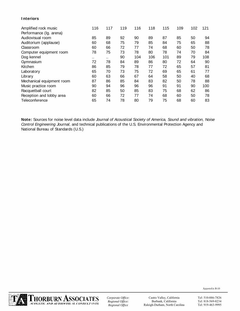
Interiors Amplified rock music 116 117 119 116 118 115 109 102 121 Performance (lg. arena) Audiovisual room 85 89 92 90 89 87 85 50 94 Auditorium (applause) 60 68 75 79 85 84 75 65 88 Classroom 60 66 72 77 74 68 60 50 78 Computer equipment room 78 75 73 78 80 78 74 70 84 Dog kennel .. .. 90 104 106 101 89 79 108 Gymnasium 72 78 84 89 86 80 72 64 90 Kitchen 86 85 79 78 77 72 65 57 81 Laboratory 65 70 73 75 72 69 65 61 77 Library 60 63 66 67 64 58 50 40 68 Mechanical equipment room 87 86 85 84 83 82 50 78 88 Music practice room 90 94 96 96 96 91 91 90 100 Racquetball court 82 85 50 85 83 75 68 62 86 Reception and lobby area 60 66 72 77 74 68 60 50 78 Teleconference 65 74 78 80 79 75 68 60 83 Note: Sources for noise level data include Journal of Acoustical Society of America, Sound and vibration, Noise Control Engineering Journal, and technical publications of the U.S. Environmental Protection Agency and National Bureau of Standards (U.S.)

`
Appendix B-11
Corporate Office: Regional Office: Regional Office
Castro Valley, California Burbank, California
Raleigh-Durham, North Carolina
Tel: 510-886-7826Tel: 818-569-0234Tel: 919-463-9995
MECHANICAL EQUIPMENT NOISE LEVEL DATA Sound Pressure Level (dB) 3 ft. from equipment
Equipment 63 Hz 125Hz 250Hz 500Hz 1000Hz 2000Hz 4000Hz 8000Hz dBA Absorption machine 91 86 86 86 83 80 77 72 8
Axial fan 98 99 99 98 97 95 91 87 102 Boiler 92 92 89 86 83 80 77 74 89 Centrifugal fan 86 95 89 90 87 82 76 77 92 Chiller, centrifugal 80 85 87 87 90 98 91 87 100 Compressor, air 86 84 86 87 86 84 80 75 91 Condenser 99 92 90 90 89 85 76 68 92 Cooling tower 102 102 97 94 90 88 84 79 97 Fan coil unit 57 55 53 50 48 42 38 32 53 Induction unit 57 58 56 54 45 40 35 33 54 PTAC 64 64 65 56 53 48 44 37 59 Pump 75 80 82 87 86 80 77 75 89 Rooftop unit 95 93 89 85 80 75 69 66 87 Warm-air furnace 65 65 59 53 48 45 39 30 57 Reference "Noise from Construction Equipment and Operations, Building Equipment, and Home
Appliances," U.S. Environmental Protection Agency, NTID 300.1, Washington, December 1971. From: “Architectural Acoustics” by David Egan r:\market\aia-csi class\appendix\appendix b.doc

`
Appendix C-2
Corporate Office: Regional Office: Regional Office
Castro Valley, California Burbank, California
Raleigh-Durham, North Carolina
Tel: 510-886-7826Tel: 818-569-0234Tel: 919-463-9995
where Lw =sound power level (dB) W = sound power (W)
Wo = reference sound power (W, usually taken as 10-12 W)
Note: Lw is used by testing laboratories to rate a sound source independently of its environment.
Noise Reduction:
NR = LI - L2
where NR = noise reduction, or the difference in sound levels between two conditions (dB) LI = sound level under one condition, usually taken as the higher
value (dB) L2 = sound level under another condition (dB)
where NR = [see formula (6)] l1 = sound intensity under one condition (W/M2) l2 = sound intensity under another condition (W/M2) Sound Source Under Free Field Conditions: Outdoors
where l = sound intensity (W/ M2) W = sound power (W) = 3.14
d = distance from sound source (m) If distance is given in feet, use l= W/4 d2 X 10.76
Inverse-Square Law:
Lw = 10 logWW0
NR = 10 log I1I2
I = W4πd 2

`
Appendix C-3
Corporate Office: Regional Office: Regional Office
Castro Valley, California Burbank, California
Raleigh-Durham, North Carolina
Tel: 510-886-7826Tel: 818-569-0234Tel: 919-463-9995
where l1 = sound intensity at distance di (W/M2)
l2 = sound intensity at distance d2 (W/M2) d = [see formula (8)]
where NR = noise reduction (dB)
d2 = distance from sound source at one location (ft or m) d1= distance from sound source at another location (ft or m) Note: The sound level is decreased outdoors by 6 dB for each doubling of distance
from a point source because 20 log (2) = 20 (0.3) = 6 dB. For line sources, use 1 0 log in formula.
r:\market\aia-csi class\appendix\appendix c.doc
2
( I1I2
= d2
d1 )
NR = 20 log d 2d 1

`
Appendix C-4
Corporate Office: Regional Office: Regional Office
Castro Valley, California Burbank, California
Raleigh-Durham, North Carolina
Tel: 510-886-7826Tel: 818-569-0234Tel: 919-463-9995
Sound Source in Reverberant Field: Indoors where a = total room absorption at given frequency (sabins)
S= surface area (ft2) a = sound absorption coefficient at given frequency (decimal percent)
where l = sound intensity in reverberant field (W/M2) W = sound power (W) a = total room absorption (sabins) If absorption is calculated in M2, use l = W/I a.
where l1 = sound intensity in reverberant field at total room absorption a, (W/M2)
l2= sound intensity in reverberant field at total room absorption a2 (W/M2)
a = [see formula (11)
where NR room noise reduction in reverberant field (dB) a2 = total room absorption after treatment (sabins) a1 = total room absorption before treatment (sabins)
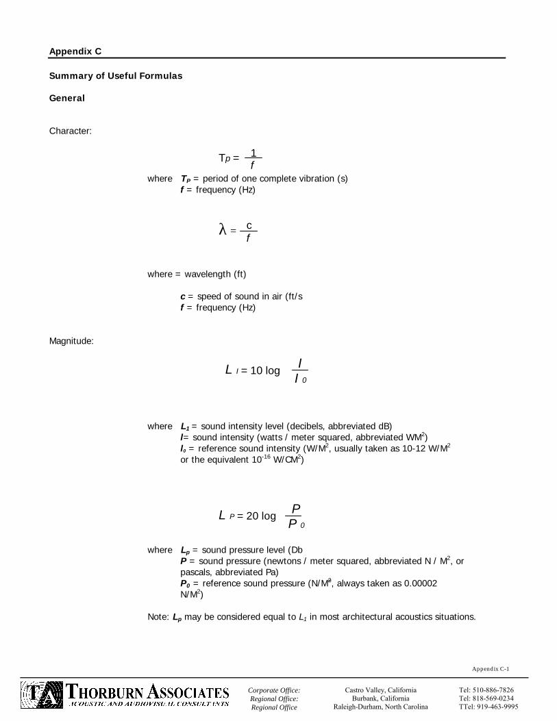
`
Appendix C-1
Corporate Office: Regional Office: Regional Office
Castro Valley, California Burbank, California
Raleigh-Durham, North Carolina
Tel: 510-886-7826Tel: 818-569-0234TTel: 919-463-9995
Appendix C Summary of Useful Formulas General Character:
where TP = period of one complete vibration (s) f = frequency (Hz)
where = wavelength (ft) c = speed of sound in air (ft/s f = frequency (Hz) Magnitude:
where L1 = sound intensity level (decibels, abbreviated dB) l= sound intensity (watts / meter squared, abbreviated WM2) l0 = reference sound intensity (W/M2, usually taken as 10-12 W/M2 or the equivalent 10-16 W/CM2)
where Lp = sound pressure level (Db
P = sound pressure (newtons / meter squared, abbreviated N / M2, or pascals, abbreviated Pa) P0 = reference sound pressure (N/M2, always taken as 0.00002
N/M2) Note: Lp may be considered equal to L1 in most architectural acoustics situations.
1f
Tp =
cf
λ =
L I = 10 log II 0
L P = 20 log PP 0

`
Appendix C-5
Corporate Office: Regional Office: Regional Office
Castro Valley, California Burbank, California
Raleigh-Durham, North Carolina
Tel: 510-886-7826Tel: 818-569-0234Tel: 919-463-9995
LP = LW – 10 log a + 16
where Lp = sound pressure level (dB) Lw =sound power level (dB) a = [see formula (11)] Sabine Formula:
where T = reverberation time, or time required for sound to decay 60 dB after source has stopped (s) V = room volume (ft3) a= [see formula (11)]
Eyring Formula:
where T =reverberation time (s)
V =room volume (ft3) S = total surface area (ft2) mean sound absorption coefficient (decimal percent)
Note: Use the constant 0. 16 instead of 0.05 where absorption is calculated in metric sabins (surface areas in M2). In large.rooms, add air absorption to denominator of T formulas.
Noise Reduction Coefficient.
with result rounded to nearest 18) 0.05 increment
where NRC = noise reduction coefficient (decimal percent) a = sound absorption coefficient (decimal percent)

`
Appendix C-6
Corporate Office: Regional Office: Regional Office
Castro Valley, California Burbank, California
Raleigh-Durham, North Carolina
Tel: 510-886-7826Tel: 818-569-0234Tel: 919-463-9995
Sound Transmission Through Common Barrier
TL = L1 – L2 where TL = sound transmission loss (dB)
LI = sound level in laboratory source room (dB) L2 = sound level in laboratory receiving room (dB)
where TL = sound transmission loss (dB)
= sound transmission coefficient (no units) Composite TL:
where TL = sound transmission loss of composite barrier (dB) ÓS = S1 + S2 +. . .+Sn= total surface area of barrier (ft2)
ΣΣττS = ττ S1 + ττ2S2 +ττnSn
= sum of sound transmission coefficients of each part of barrier times the respective areas (ft2)
Homogeneous Materials:
TL = 20 + 20 log G
where TL = sound transmission loss at 500 Hz (dB) G = surface density (lb/ft2)
where NR = LI - L2 = noise reduction, or difference in sound levels, between rooms (dB)
TL = sound transmission loss of common barrier (dB) a2 = absorption in receiving room (sabins) S = surface area of common barrier (ft2)

`
Appendix C-7
Corporate Office: Regional Office: Regional Office
Castro Valley, California Burbank, California
Raleigh-Durham, North Carolina
Tel: 510-886-7826Tel: 818-569-0234Tel: 919-463-9995
Mechanical System Noise and Vibrations Vibration Isolation:
where fn = natural or resonant frequency of isolator (Hz) y = spring static deflection (in) Lined Duct:
where A = attenuation for lined duct (dB/ft) a = sound absorption coefficient of duct liner (decimal percent)
P = perimeter of rectangular duct (in) S = cross-sectional open area of duct (in2) SoundSystems Loudspeaker-to-Listener Distance: where d = maximum loudspeaker-to-listener distance (ft) Q = loudspeaker directivity (no units) V = room volume (ft3)
T = reverberation time (s) Distributed Loudspeakers for Seated Audience:
S =
where S = spacing between loudspeakers (ft) H = floor-to-ceiling height (ft)
Background Masking:

`
Appendix C-8
Corporate Office: Regional Office: Regional Office
Castro Valley, California Burbank, California
Raleigh-Durham, North Carolina
Tel: 510-886-7826Tel: 818-569-0234Tel: 919-463-9995
SUMMARY OF USEFUL FORMULAS 393 where S = spacing between loudspeakers (ft) D = plenum depth (ft) H = floor-to-ceiling height (ft) Miscellaneous Vibrating Panels: 170 fr @wd (29) where fr = resonant frequency (Hz) w = surface weight of panel (lb/ft2) d = depth of airspace behind panel (in) Perforated Facings: 40-P (30) D where f, = critical frequency (Hz) P = open area (percent) D = hole diameter (in) Double Walls: 170 fo (GI X G2) d (31 + G2 where fo = mass-air-mass resonant frequency (Hz) GI = weight of panel layers on one side (lb/ft2) G2 = weight of panel layers, on opposite side (lb/ft2) d = thickness of cavity insulation times F2 plus cavity depth not containing insulation (in)

`
Appendix C-9
Corporate Office: Regional Office: Regional Office
Castro Valley, California Burbank, California
Raleigh-Durham, North Carolina
Tel: 510-886-7826Tel: 818-569-0234Tel: 919-463-9995
394 SUMMARY OF USEFUL FORMULAS Outdoor Barriers: A 10 log H2 + 10 log f - 17 (32) R where A = attenuation for thin-wall barrier (dB) H = height of barrier above line of sight between source and receiver (ft) R = distance from source (or receiver) to barrier (ft) Note: Use smaller of the two distances. f = frequency (Hz) Ceiling Height for Auditoriums: H = 20T (33) where H = average ceiling height for auditorium with upholstered seats and absorptive rear wall (ft) T = mid-frequency reverberation time (s) From: “Architectural Acoustics” by David Egan r:\market\aia-csi class\appendix\appendix c.doc

`
Appendix D-1
Corporate Office: Regional Office: Regional Office
Castro Valley, California Burbank, California
Raleigh-Durham, North Carolina
Tel: 510-886-7826Tel: 818-569-0234Tel: 919-463-9995
APPENDIX D: DEFINITION OF TERMS
Acoustical Terms
Absorption A totally absorptive material will not reflect any energy back into the room. In the case of a sound wave, the sound will cease to exist. Energy can neither be created nor destroyed, but it can be converted from one form to another. Absorption is the conversion of sound energy to heat.
Acoustical Material Any material considered in terms of its acoustical properties. Commonly and especially, a material designed to absorb sound.
Airborne Sound Sound that arrives at the point of interest, such as one side of a partition, by propagation through air.
Airflow Resistance The quotient of the air pressure difference across a specimen divided by the volume velocity of airflow through the specimen. The pressure difference and the volume velocity may be either steady or alternating.
Anechoic Echo free; an anechoic room is one whose walls, ceiling, and floor are covered with sound absorbing material, usually in the shape of wedges.
Arithmetic Mean Sound Pressure Level Of several related sound pressure levels measured at different positions or different times, or both, in a specified frequency band. The sum of the sound pressure levels divided by the number of levels. NOTE - The arithmetic mean sound pressure level is sometimes used to approximate the average sound pressure level. The accuracy of this approximation depends upon the range of sound pressure levels.
Average Sound Pressure Level Of several related sound pressure levels measured at different positions or different times, or both, in a specified frequency band, ten times the common logarithm of the arithmetic mean of the squared pressure ratios from which the individual levels were derived. NOTE - An average sound pressure level obtained by integrating and averaging during certain time periods is often called equivalent sound pressure level and, when A-weighted, equivalent sound level.
Background or Ambient Noise Level Ambient noise level is defined as the sound level that is typically observed on the measurement instrument, in the absence of individual identifiable acoustical events that are usually far from the listener. Noise from all sources unrelated to a particular sound that is the object of interest. Background noise may include airborne, structureborne, and instrument noise. The composite of airborne sound from many sources near and far associated with a given environment. No particular sound is singled out for interest.
Characteristic Impedance of the Medium The specific normal acoustic impedance at a point in a plane wave in a free field. It is a pure specific resistance since the sound pressure and the particle velocity are in phase and it is equal in magnitude to the product of the density of the medium and the speed of sound in the medium.
Community Noise Equivalent Level (CNEL) A descriptor for the 24-hour A-weighted average noise level. The CNEL concept accounts for the increased acoustical sensitivity of people to noise during the evening and nighttime hours. Sound levels during the hours from 7:00 p.m. to 10:00 p.m. are penalized 5 dB; sound levels during the hours from 10:00 p.m. to 7:00 a.m. are penalized 10 dB. A 10 dB increase in sound level is perceived by people to be twice as loud.
Cutoff Frequency Of an anechoic wedge or set of wedges, the lowest frequency above which the normal incidence sound absorption coefficient is at least 0.990.
Damp To cause a loss or dissipation of the oscillatory or vibrational energy of an electrical or mechanical system.

`
Appendix D-2
Corporate Office: Regional Office: Regional Office
Castro Valley, California Burbank, California
Raleigh-Durham, North Carolina
Tel: 510-886-7826Tel: 818-569-0234Tel: 919-463-9995
Day/Night Noise Level (DNL) The Day/Night Noise Level is the sound level which corresponds to average human sensitivity to sound levels in decibels. DNL encompasses several parameters including amplitude in decibels which corresponds to loudness, time averaging and increased sensitivity to noise at night and the frequency or pitch at which sound occur. More specifically, the DNL sound level corresponds to an energy average during a 24-hour period. The nighttime hours from 10 pm to 7 am are twice as sensitive, that is, with a 10 decibel penalty applied, due to increased human sensitivity during the night. The DNL is an A-weighted sound level. A-weighting is a filter which is applied to the microphone signal which approximates human sensitivity to different frequencies, i.e., pitch. Human hearing is most sensitive in the speech range and least sensitive at low frequencies. The units of the day/night (DNL) sound level are dBA.
dB(A) A-weighted sound pressure level (or noise level) represents the noisiness or loudness of a sound by weighting the amplitudes of various acoustical frequencies to correspond more closely with human hearing. A 10-dB (decibel) increase in noise level is perceived to be twice as loud. A-weighting is specified by the U.S. EPA, OSHA, Caltrans, and others for use in noise measurements.
dB(C) C-weighted sound pressure level (or noise level) represents the “overall” or wideband measurement of sound level. The response is fairly uniform from 50 to 5000 Hz, therefore C-weighting more accurately measures the overall acoustic energy, without regard to how humans actually hear.
Decay Rate The rate of decrease of sound pressure level after the source of sound has stopped: for vibration, the rate of decrease of vibratory acceleration, velocity, or displacement level after the excitation has stopped.
Decibel (dB) the term used to identify ten times the common logarithm of the ratio of two like quantities proportional to power or energy. One decibel corresponds to a power ratio of 10 0.1 and n decibels corresponds to a power ration of (10 0.1) n. The term used to identify ten times the common logarithm of the ratio of two like quantities proportional to power or energy. (See level, sound transmission loss.) Thus, one decibel corresponds to a power ratio of 100.1 and n decibels corresponds to a power ratio of (100.1)n. NOTE - Since the decibel expresses the ratio of two like quantities, it has no dimensions. It is, however, common practice to treat "decibel" as a unit as, for example, in the sentence, “The average sound pressure level in the room is 45 decibels."
Diffraction A change in the direction of propagation of sound energy in the neighborhood of a boundary discontinuity, such as the edge of a reflective or absorptive surface.
Diffuse Sound Field the sound in a region where the intensity is the same in all directions and at every point.
Diffusion A diffuse field is a combination of sound waves that are scattered in direction and time. Diffusion is the most significant of the three tools because of two important components. First, diffusion simultaneously increases the distribution of, and modifies the direction of sound without removing energy from within the space (spatial response). Second, diffused sound energy is distributed in time (temporal response). The listeners perception of an expanded space is created by the combination of spatial and temporal components. Plastic grills are placed in front of fluorescent tubes to evenly distribute their light throughout the room. That is the spatial aspect of diffusion.
Direct Sound Field The sound that arrives directly from a source without reflection.
Echo A long delayed, distinct reflections of sufficient sound level to be clearly heard above the general reverberation as a repetition of the original sound.
Field Impact Insulation Class (FIIC) A single figure rating which quantifies the property of a floor/ceiling construction to reduce footfall-generated noise as measured in the field. Increasing IIC values correspond to improved impact insulation.
Field Sound Transmission Class (FSTC) A single-figure rating which quantifies the sound insulation properties of a partition as measured in the field. Numerically, STC represents the number of decibels of speech sound reduction from one side of the partition to the other. The STC is intended for use when speech and office noise constitute the principal noise problem. Increasing FSTC values corresponds to improved sound insulation. Sound transmission class calculated in accordance with Classification ASTM E 413 using values of field transmission loss.
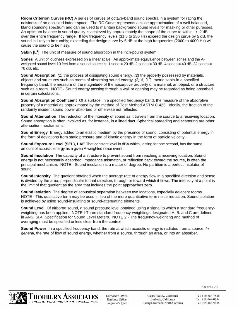
`
Appendix D-5
Corporate Office: Regional Office: Regional Office
Castro Valley, California Burbank, California
Raleigh-Durham, North Carolina
Tel: 510-886-7826Tel: 818-569-0234Tel: 919-463-9995
Room Criterion Curves (RC) A series of curves of octave-band sound spectra in a system for rating the noisiness of an occupied indoor space. The RC Curve represents a close approximation of a well balanced, bland sounding spectrum and can be used to maintain background sound levels for masking or other purposes. An optimum balance in sound quality is achieved by approximately the shape of the curve to within +/- 2 dB over the entire frequency range. If low frequency levels (31.5 to 250 Hz) exceed the design curve by 5 dB, the sound is likely to be rumbly; exceeding the design curve by 5 dB at the high frequencies (2000 to 4000 Hz) will cause the sound to be hissy.
Sabin [L2] The unit of measure of sound absorption in the inch-pound system.
Sones A unit of loudness expressed on a linear scale. An approximate equivalence between sones and the A-weighted sound level 10 feet from a sound source is: 1 sone = 20 dB; 2 sones = 30 dB; 4 sones = 40 dB; 32 sones = 70 dB, etc.
Sound Absorption (1) the process of dissipating sound energy. (2) the property possessed by materials, objects and structures such as rooms of absorbing sound energy. (3) A; [L2]; metric sabin-in a specified frequency band, the measure of the magnitude of the absorptive property of a material, an object, or a structure such as a room. NOTE - Sound energy passing through a wall or opening may be regarded as being absorbed in certain calculations.
Sound Absorption Coefficient Of a surface, in a specified frequency band, the measure of the absorptive property of a material as approximated by the method of Test Method ASTM C 423. Ideally, the fraction of the randomly incident sound power absorbed or otherwise not reflected.
Sound Attenuation The reduction of the intensity of sound as it travels from the source to a receiving location. Sound absorption is often involved as, for instance, in a lined duct. Spherical spreading and scattering are other attenuation mechanisms.
Sound Energy Energy added to an elastic medium by the presence of sound, consisting of potential energy in the form of deviations from static pressure and of kinetic energy in the form of particle velocity.
Sound Exposure Level (SEL), LAE That constant level in dBA which, lasting for one second, has the same amount of acoustic energy as a given A-weighted noise event.
Sound Insulation The capacity of a structure to prevent sound from reaching a receiving location. Sound energy is not necessarily absorbed; impedance mismatch, or reflection back toward the source, is often the principal mechanism. NOTE - Sound insulation is a matter of degree. No partition is a perfect insulator of sound.
Sound Intensity The quotient obtained when the average rate of energy flow in a specified direction and sense is divided by the area, perpendicular to that direction, through or toward which it flows. The intensity at a point is the limit of that quotient as the area that includes the point approaches zero.
Sound Isolation The degree of acoustical separation between two locations, especially adjacent rooms. NOTE - This qualitative term may be used in lieu of the more quantitative term noise reduction. Sound isolation is achieved by using sound-insulating or sound-attenuating elements.
Sound Level Of airborne sound, a sound pressure level obtained using a signal to which a standard frequency-weighting has been applied. NOTE I-Three standard frequency-weightings designated A. B. and C are defined in ANSI SI.4, Specification for Sound Level Meters. NOTE 2 - The frequency-weighting and method of averaging must be specified unless clear from the context.
Sound Power In a specified frequency band, the rate at which acoustic energy is radiated from a source. In general, the rate of flow of sound energy, whether from a source, through an area, or into an absorber.

`
Appendix D-3
Corporate Office: Regional Office: Regional Office
Castro Valley, California Burbank, California
Raleigh-Durham, North Carolina
Tel: 510-886-7826Tel: 818-569-0234Tel: 919-463-9995
Field Transmission Loss, FTL Sound transmission loss measured in accordance with ASTM E 336.
Flanking Paths Indirect paths through which sound energy can bypass constructions and seriously degrade the transmission loss (TL) rating of that construction. Example flanking paths are open ceiling plenums and attics, continuous side walls and floors, air duct and pipe penetrations, joist and crawl spaces. Flanking paths can be prevented by careful design of all connections, penetrations, and adjacent framing systems.
Flanking Transmission Transmission of sound from the source to a receiving location by a path other than that under consideration.
Flutter Echo Can be heard as a "rattle" or "clicking" from a hand clap. May be present in small rooms or narrow spaces with parallel walls. Can be effectively controlled with sound absorbing materials.
Frequency The rate of repetition of a periodic event. Sound in air consists of a series of compressions and rarefactions due to air particles set into motion by a vibrating source. The frequency of this sound wave is determined by the number of times per second a given air molecule vibrates around its neutral position. The greater the number of complete vibrations (cycles) the higher the frequency. The unit of frequency is the hertz (Hz).
Impact Isolation Class (IIC) The Impact Isolation Class is single figure rating which quantifies impact noise on a floor through a ceiling, such as that produced by foot-falls. A standardized device generates the impact sound by dropping 5 hammers which impart a known energy into the floor/ceiling construction. The resulting sound pressure level is measured in the receiving room below in frequency bandwidths comparable to those used in sound transmission loss measurements. The procedure and curve fitting are defined in ASTM Standard E492. Increasing IIC values correspond to improved impact insulation. A single-number rating derived from measured values of normalized impact sound pressure levels in accordance with Annex Al of Method ASTM E 492. It provides an estimate of the impact sound insulating performance of a floor-ceiling assembly.
INCE Institute of Noise Control Engineering
Insertion Loss (IL) Of a silencer or other sound-reducing element, in a specified frequency band, the decrease in sound power level, measured at the location of the receiver, when a sound insulator or a sound attenuator is inserted in the transmission path between the source and the receiver.
Leq The equivalent steady-state A-weighted sound level that, in a stated period of time, would contain the same acoustic energy as the time-varying sound level during the same time period.
Level (L) Ten times the common logarithm of the ratio of a quantity proportional to power or energy to a reference quantity of the same kind. (See sound power level, sound pressure levels) The quantity so obtained is expressed in decibels.
Level Reduction (LR) In a specified frequency band, the decrease in sound pressure level, measured at the location of the receiver, when a barrier or other sound-reducing element is placed between the source and the receiver. NOTE - Level reduction is a useful measure in circumstances when measures of transmission loss, insertion loss, or noise reduction are not possible.
Metric Sabin, [L2] The unit of measure of sound absorption in the metre-kilogram-second system of units.
Noise Criteria (NC) Noise Criteria ratings approximate the human perception of "noisiness" within buildings. The NC rating is based on 8 octave band sound pressure level measurements in which building machinery normally produce sound which can be annoying to the occupants. These eight measurements are compared with a family of curves. The highest curve under which all the data fall is the rating. This rating is not applicable to pure tones where a penalty must be added since they are perceived to be more "noisy." High NC ratings are louder and an increase by 10 points approximates a doubling of perceived loudness.
Noise Isolation Class (NIC) The noise isolation Class is a single number rating describing the attenuation of sound through building partitions. The rating is derived from measured values of noise reduction between two enclosed spaces that are connected by one or more paths. In general, the more massive a material or construction, the higher its NIC rating. A single-number rating calculated in accordance with Classification ASTM E 413 using measured values of noise reduction. It provides an estimate of the sound isolation between two enclosed spaces that are acoustically connected by one or more paths.
Noise Reduction (NR) In a specified frequency band, the difference between the average sound pressure levels measured in two enclosed spaces or rooms due to one or more sound sources in one of them. NOTE - It is implied that in each room there is a meaningful average level: that is, that in each room the individual observations are randomly distributed about the average value, with no systematic variation with position within

`
Appendix D-4
Corporate Office: Regional Office: Regional Office
Castro Valley, California Burbank, California
Raleigh-Durham, North Carolina
Tel: 510-886-7826Tel: 818-569-0234Tel: 919-463-9995
the permissible measurement region. Noise reduction becomes meaningless and should not be used in situations where this condition is not met.
Noise Reduction Coefficient (NRC) The NRC is intended as a single-number rating of the sound-absorbing efficiency at mid-frequencies. It is not, as its name implies, the difference in sound levels between two conditions or between rooms. It is the numerical average of the sound absorption coefficients at 250, 500, 1000, and 2000 Hz for a specific material and mounting condition. A single-number rating derived from measured values of sound absorption coefficients in accordance with 11.7 of Test Method ASTM C 423. It provides an estimate of the sound absorptive property of an acoustical material.
Noise Sources Anything that is not part of the experience that is being tested. This would include but is not limited to adjacent building systems, mechanical equipment, ride equipment, adjacent show audio or effects, traffic noise, and the natural environment (rain).
Normal Incidence Sound Absorption Coefficient Of a surface, at a specified frequency, the fraction of the perpendicularly incident sound power absorbed or otherwise not reflected.
Normalized Noise Isolation Class (NNIC) A single-number rating calculated in accordance with Classification ASTM E 413 using measured values of normalized noise reduction. (See normalized noise reduction.)
Normalized Noise Reduction (NNR) Between two rooms, in a specified frequency band, the value that the noise reduction in a given field test would have if the reverberation time in the receiving room were 0.5 s. NNR is calculated as follows: NNR = NR + 10 log (T/0.5) where: NR = noise reduction, dB and T = reverberation time in receiving room, s. NOTE - The normalized noise reduction is intended to approximate the noise reduction that would exist between two ordinarily furnished rooms.
Outdoor-Indoor Transmission Loss (OITL) Of a building facade, in a specified frequency band, ten times the common logarithm of the ratio of the airborne sound power incident on the exterior of the facade to the sound power transmitted by the facade and radiated to the interior. The quantity so obtained is expressed in decibels.
Percentile Level, L(N),(T) That noise level in dBA exceeded for N% of the measurement time T.
Pink Noise Noise with a continuous frequency spectrum and with equal power per constant percentage bandwidth. For example, equal power in any one-third octave band.
Pitch The subjective response of human hearing to frequency. Low frequencies generally are considered "boomy" and high frequencies "screechy" or "hissy".
Preferred Noise Criteria (PNC) Revisions of NC Curves used for similar situations in rating the noise environments of indoor spaces. Developed to answer objections regarding the adequacy of NC Curves at the low and high frequencies; they are based on both the preferred speech-interference level and the loudness level.
Receiving Room In architectural acoustical measurements, the room in which the sound transmitted from the source room is measured.
Reflection A perfectly reflective surface will absorb no wave energy, but return all that energy back to the space it came from. The sound wave (traveling toward the reflective surface) can be simplified as a straight line (black line). The reflected wave (gray line) will leave the surface at an opposite and equal angle. A mirror is a reflective surface for light energy. Shinning a beam of light into a mirror will demonstrate the same behavior as sound striking an acoustically reflective surface. One example of a very reflective acoustic surface is a concrete wall.
Reverberant Sound Field The sound in an enclosed or partially enclosed space that has been reflected repeatedly or continuously from the boundaries.
Reverberant Sound Sound that builds up and decays gradually and can be "stored" in a room for an appreciable time.
Reverberation The persistence of sound in an enclosed or partially enclosed space after the source of sound has stopped: by extension, in some contexts, the sound that so persists.
Reverberation Room A room so designed that the reverberant sound field closely approximates a diffuse sound field, both in the steady state when the sound source is on, and during decay after the source of sound has stopped.
Reverberation Time(RT60 ) The time required for the stored or reverberant sound to decrease by 60 dB.

`
Appendix D-6
Corporate Office: Regional Office: Regional Office
Castro Valley, California Burbank, California
Raleigh-Durham, North Carolina
Tel: 510-886-7826Tel: 818-569-0234Tel: 919-463-9995
Sound Power Level, Lw Of airborne sound, ten times the common logarithm of the ratio of the sound power under consideration to the standard reference power of 1 pW. The quantity so obtained is expressed in decibels. NOTE - The pressures are squared because pressure squared. rather than pressure, is proportional to power or energy.
Sound Pressure A fluctuating pressure superimposed on the static pressure by the presence of sound. In analogy with alternating voltage its magnitude can be expressed in several ways, such as instantaneous sound pressure or peak sound pressure, but the unqualified term means root-mean-square sound pressure. In air, the static pressure is barometric pressure.
Sound Transmission Class (STC) A single-number rating used to compare walls, floor-ceiling assemblies and doors for their sound-insulating properties with respect to speech and small appliance noise. The STC is derived from laboratory measurements of sound transmission loss across a series of 16 tests bands. A single-number rating calculated in accordance with Classification ASTM E 413 using values of sound transmission loss. It provides an estimate of the performance of a partition in certain common sound insulation problems.
Sound Transmission Coefficient In a specified frequency band, the fraction of the airborne sound power incident on the partition that is transmitted by the partition and radiated on the other side. NOTE - Unless qualified, the term denotes the value obtained when the specimen is exposed to a diffuse sound field as approximated, for example, in reverberation rooms meeting the requirements of Test Method ASTM E 90.
Sound Transmission Loss (TL) Of a partition, in a specified frequency band, ten times the common logarithm of the ratio of the airborne sound power incident on the partition to the sound power transmitted by the partition and radiated on the other side. The quantity so obtained is expressed in decibels. NOTE - Unless qualified, the term denotes the sound transmission loss obtained when the specimen is exposed to a diffuse sound field as approximated, for example, in reverberation rooms meeting the requirements of Test Method ASTM E 90. A measurement, in decibels, of how much sound energy is reduced by transmission through materials. In general, the more massive a material the higher its TL
Structureborne Sound Sound that arrives at the point of interest, such as the edge of a partition, by propagation through a solid structure.
Thermal Insulation A material or assembly of materials used primarily to provide resistance to heat flow.
Unit measurement, a precisely specified quantity in terms of which the magnitudes of other quantities of the same kind can be stated.
Vibration Isolation A reduction, attained by the use of a resilient coupling, in the capacity of a system to vibrate in response to mechanical excitation.
White Noise Noise with a continuous frequency spectrum and with equal power per unit bandwidth. For example. equal power in any band of 100-Hz width.
Related Documents


