arXiv:0705.2754v1 [physics.class-ph] 18 May 2007 Acoustic response of a rigid frame porous medium slab with a periodic set of inclusions J.-P. Groby ∗ , A. Wirgin † , and L. de Ryck ‡ , and W. Lauriks § February 1, 2008 Abstract The acoustic response of a rigid frame porous slab with a periodic set of inclusions is cal- culated by use of a multipole method. The acoustic properties, in particular the absorption, of such a structure are then derived and studied. Numerical results together with a modal anal- ysis show that the addition of a periodic set of high-contrast inclusions leads to quasi-modes excitation of both the slab and the gratings, and to a large increase of the acoustic absorption of the initial slab, this being partly due to the quasi-modes excitation. Keywords: absorption of sound, porous materials, periodic inclusions, gratings 1 Introduction This work was initially motivated by the design problem connected with the determination of the optimal profile of a continuous and/or discontinuous spatial distribution of the material/geometric properties of porous materials for the absorption of sound. The equations that model the acoustic wave propagation in a macroscopically inhomogeneous rigid frame porous medium were derived in [10]. Acoustic properties of porous materials (foam) suffer from a lack of absorption particularly at low frequency. The usual way to solve this problem is by multi-layering [26]. In [24], the authors considered the reflection of a plane acoustic wave by a porous slab that presents a periodic set of pits. The medium is homogenized and its behavior is described in [5]. This leads to a drastic increase of the absorption coeficient at low frequency. In [27] the authors considered the transmission of an acoustic wave through a porous medium in which randomly- arranged metallic rods are imbedded, converted, by a procedure called ISAβ, into an equivalent homogeneous medium which exhibits decreased transmission and increased absorption. Periodic arrangements of either surface irregularities or volume heterogeneities usually lead to energy entrapment either at the surface or inside the structure, respectively, this being strongly linked to mode excitation, and to an increase of the absorption coefficient (first noticed by Wood [31] and partially explained by Cutler [7]). The particular properties of such structures have been studied in mechanics, with application to composite materials [6, 17, 32], in optics, initially * Correspondence to: J.-P. Groby, CMAP, UMR 7641 CNRS/Ecole Polytechnique, 91128 Palaiseau cedex, France † LMA, UPR 7051 CNRS, 31 Chemin Joseph-Aiguier, 13402 Marseille cedex 20, France ‡ Laboratory of Acoustics and Thermal Physics, Celestijnenlaan 200D, B-3001 Leuven, Belgium § Laboratory of Acoustics and Thermal Physics, Celestijnenlaan 200D, B-3001 Leuven, Belgium 1

Welcome message from author
This document is posted to help you gain knowledge. Please leave a comment to let me know what you think about it! Share it to your friends and learn new things together.
Transcript
arX
iv:0
705.
2754
v1 [
phys
ics.
clas
s-ph
] 1
8 M
ay 2
007
Acoustic response of a rigid frame porous medium slab with a
periodic set of inclusions
J.-P. Groby ∗, A. Wirgin †, and L. de Ryck‡, and W. Lauriks §
February 1, 2008
Abstract
The acoustic response of a rigid frame porous slab with a periodic set of inclusions is cal-culated by use of a multipole method. The acoustic properties, in particular the absorption, ofsuch a structure are then derived and studied. Numerical results together with a modal anal-ysis show that the addition of a periodic set of high-contrast inclusions leads to quasi-modesexcitation of both the slab and the gratings, and to a large increase of the acoustic absorptionof the initial slab, this being partly due to the quasi-modes excitation.
Keywords: absorption of sound, porous materials, periodic inclusions, gratings
1 Introduction
This work was initially motivated by the design problem connected with the determination of theoptimal profile of a continuous and/or discontinuous spatial distribution of the material/geometricproperties of porous materials for the absorption of sound. The equations that model the acousticwave propagation in a macroscopically inhomogeneous rigid frame porous medium were derived in[10]. Acoustic properties of porous materials (foam) suffer from a lack of absorption particularlyat low frequency. The usual way to solve this problem is by multi-layering [26].
In [24], the authors considered the reflection of a plane acoustic wave by a porous slab thatpresents a periodic set of pits. The medium is homogenized and its behavior is described in [5].This leads to a drastic increase of the absorption coeficient at low frequency. In [27] the authorsconsidered the transmission of an acoustic wave through a porous medium in which randomly-arranged metallic rods are imbedded, converted, by a procedure called ISAβ, into an equivalenthomogeneous medium which exhibits decreased transmission and increased absorption.
Periodic arrangements of either surface irregularities or volume heterogeneities usually lead toenergy entrapment either at the surface or inside the structure, respectively, this being stronglylinked to mode excitation, and to an increase of the absorption coefficient (first noticed by Wood[31] and partially explained by Cutler [7]). The particular properties of such structures havebeen studied in mechanics, with application to composite materials [6, 17, 32], in optics, initially
∗Correspondence to: J.-P. Groby, CMAP, UMR 7641 CNRS/Ecole Polytechnique, 91128 Palaiseau cedex, France†LMA, UPR 7051 CNRS, 31 Chemin Joseph-Aiguier, 13402 Marseille cedex 20, France‡Laboratory of Acoustics and Thermal Physics, Celestijnenlaan 200D, B-3001 Leuven, Belgium§Laboratory of Acoustics and Thermal Physics, Celestijnenlaan 200D, B-3001 Leuven, Belgium
1
motivated by the collection of solar energy [8, 18], with applications to photonic crystals [19, 33],in electromagnetics, with application to so-called left-handed materials [28], in geophysics, for thestudy of the “city-site” effect [3, 14]. The properties of such structures are now studied to createband-gaps for elastic or acoustic waves (phononic crystals [22, 23, 30]), but have only recently beenused for the design of sound absorbing or porous materials [9, 21, 25].
Herein, we study the influence on the acoustic absorption of the introduction of a periodic setof fluid-like circular cylinders into a macroscopically-homogeneous porous slab (the porosity beinghomogenized in the equivalent fluid model).
2 Formulation of the problem
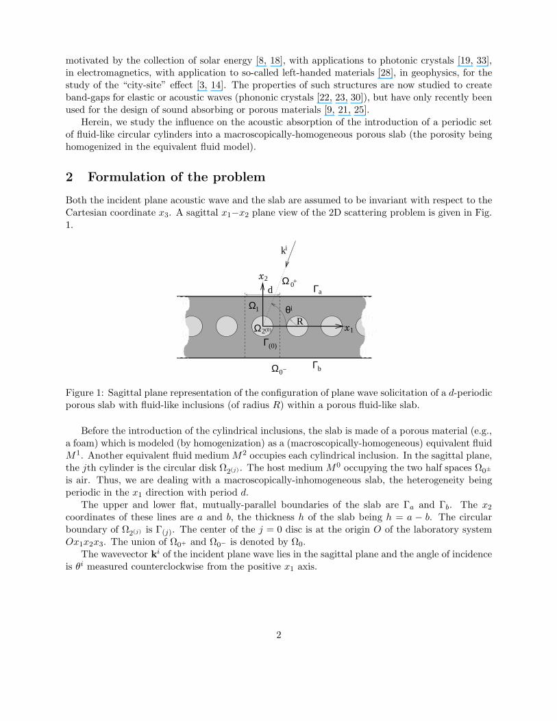
Both the incident plane acoustic wave and the slab are assumed to be invariant with respect to theCartesian coordinate x3. A sagittal x1−x2 plane view of the 2D scattering problem is given in Fig.1.
Γ
0d
+
θ
k
Ω1
i
Ω
b
i
−Ω0
x2
x1R
aΓ
Γ2Ω
(0)
(0)
Figure 1: Sagittal plane representation of the configuration of plane wave solicitation of a d-periodicporous slab with fluid-like inclusions (of radius R) within a porous fluid-like slab.
Before the introduction of the cylindrical inclusions, the slab is made of a porous material (e.g.,a foam) which is modeled (by homogenization) as a (macroscopically-homogeneous) equivalent fluidM1. Another equivalent fluid medium M2 occupies each cylindrical inclusion. In the sagittal plane,the jth cylinder is the circular disk Ω2(j) . The host medium M0 occupying the two half spaces Ω0±
is air. Thus, we are dealing with a macroscopically-inhomogeneous slab, the heterogeneity beingperiodic in the x1 direction with period d.
The upper and lower flat, mutually-parallel boundaries of the slab are Γa and Γb. The x2
coordinates of these lines are a and b, the thickness h of the slab being h = a − b. The circularboundary of Ω2(j) is Γ(j). The center of the j = 0 disc is at the origin O of the laboratory systemOx1x2x3. The union of Ω0+ and Ω0− is denoted by Ω0.
The wavevector ki of the incident plane wave lies in the sagittal plane and the angle of incidenceis θi measured counterclockwise from the positive x1 axis.
2
3 Wave equations
We designate a total pressure and wavenumber by the generic symbols p and k respectively, withp = p0± , k = k0 in Ω0± , p = p1, k = k1 in Ω1 and p = p2(j), k = k2 in Ω2(j) .
Rather than solving directly for the pressure p(x, t) (with x = (x1, x2)), we prefer to deal withp(x, ω), related to p(x, t) by the Fourier transform:
p(x, t) =
∫ ∞
−∞p(x, ω)e−iωtdω . (1)
Henceforth, we drop the ω in p(x, ω) so as to designate the latter by p(x). This function satisfiesthe Helmholtz equations
[
+ (km)2]
p(x) = 0 ; x ∈ Ωm , m = 0±, 1, 2 . (2)
In an equivalent fluid medium [10], the compressibility and density take the form
1
Ke
=γP0
φ
(
γ − (γ − 1)(
1 + i ωc
Pr2ωG(Pr2ω)
)−1) ,
ρe =ρfα∞
φ
(
1 + iωc
ωF (ω)
)
,
(3)
where ωc =σφ
ρfα∞is the Biot’s frequency cut, γ the specific heat ratio, P0 the atmospheric pressure,
Pr the Prandtl number, ρf the density of the fluid in the (interconnected) pores, φ the porosity,α∞ the tortuosity, and σ the flow resistivity. The correction functions G(Pr2ω) [2], F (ω) [20] aregiven by
G(Pr2ω) =
√
1 − iηρfα2
∞
σ2φ2Λ′2Pr2ω ,
F (ω) =
√
1 − iηρfα2
∞
σ2φ2Λ2ω.
(4)
where η is the viscosity of the fluid, Λ′ the thermal characteristic length, and Λ the viscous char-acteristic length.
The incident wave propagates in Ω0+ and is expressed by
pi(x) = Ai exp[i(ki1x1 − ki
2(x2 − a)] , (5)
wherein ki1 = −k0 cos θi, ki
2 = k0 sin θi and Ai = Ai(ω) is the signal spectrum.The new feature, with respect to the canonical case considered in [12], is the transverse period-
icity of ∪j∈ZΩ2(j) .Owing to the plane wave nature of the incident wave, and the periodic nature of ∪j∈ZΩ2(j) , one
can show that the field is quasi-periodic (Floquet theorem), i.e.,
p((x1 + nd, x2)) = p((x1, x2))eiki
1nd ; ∀x ∈ R2 ; ∀n ∈ Z . (6)
Consequently, it suffices to examine the field in the central cell of the slab which includes the diskΩ2(0) in order to obtain the fields, via the Floquet relation, in the other cells. Henceforth, we adopt
the simplified notation: Ω2 := Ω2(0) , Γ := Γ(0), p2 = p2(0).
3
4 Boundary and radiation conditions
Since M0 and M1 are fluid-like, the pressure and the normal velocity are continuous across theinterfaces Γa and Γb:
p0+(x) − p1(x) = 0, ∀x ∈ Γa , (7)
(
ρ0)−1
∂np0+(x) −
(
ρ1)−1
∂np1(x) = 0, ∀x ∈ Γa , (8)
p0−(x) − p1(x) = 0, ∀x ∈ Γb , (9)(
ρ0)−1
∂np0−(x) −(
ρ1)−1
∂np1(x) = 0, ∀x ∈ Γb , (10)
wherein n denotes the generic unit vector normal to a boundary and ∂n designates the operator∂n = n · ∇.
Since M1 and M2 are fluid-like, the pressure and normal velocity are continuous across theinterface Γ:
p2(x) − p1(x) = 0, ∀x ∈ Γ , (11)(
ρ2)−1
∂np2(x) −(
ρ1)−1
∂np1(x) = 0, ∀x ∈ Γ . (12)
The uniqueness of the solution to the forward-scattering problem is assured by the radiation con-ditions :
p0+(x) − pi(x) ∼ outgoing waves ; |x| → ∞ , x2 > a , (13)
p0−(x) ∼ outgoing waves ; ∀ |x| → ∞ , x2 < b . (14)
5 Field representations
Separation of variables, the radiation conditions, and the Floquet theorem lead to the representa-tions:
p0+(x) =
∑
p∈Z
[
e−ik02p(x2−a)δp0 + Rpe
ik02p(x2−a)
]
eik1px1 , ∀x ∈ Ω0+ , (15)
p0−(x) =∑
p∈Z
Tpei(k1px1−k0
2p(x2−b)), ∀x ∈ Ω0− , (16)
wherein δp0 is the Kronecker symbol, k1p = ki1 +
2pπ
d, k0
2p =√
(k0)2 − (k1p)2, with ℜ(
k02p
)
≥ 0 and
ℑ(
k02p
)
≥ 0.The field in the central inclusion, with [r = (r, θ)], takes the form
p2(r) =∑
l∈Z
ClJl
(
k2r)
eilθ, ∀(r, θ) ∈ Ω2 , (17)
wherein Jl is the l-th order Bessel function.It is convenient to combine Cartesian coordinates (x1, x2) and cylindrical coordinates (r, θ) to
write the field representation in Ω1. The latter takes the form of the sum (by use of the superpositionprincipe) of the diffracted field by the inclusions p1
d(x) and of the diffracted field in the slab p1s(x).
4
Because of the quasi-periodic aspect of the configuration, the diffracted field in the slab can bewritten in Cartesian coordinates as:
p1s(x) =
∑
p∈Z
(
f−1pe
−ik12px2 + f+
1peik1
2px2
)
eik1px1 . (18)
We transform Cartesian to polar coordinates by means of:
x1 = r cos (θ) , k1p = k1 cos (θp) ,
x2 = r sin (θ) , k12p = k1 sin (θp) ,
(19)
so thatp1
s(r) =∑
p∈Z
(
f−1pe
ik1r cos(θ+θp) + f+1pe
ik1r cos(θ−θp))
. (20)
Use of the identity
eik1r cos(θ−θp) =
∑
m∈Z
imJm(kr)eim(θ−θp) , (21)
leads top1
s(r) =∑
m∈Z
∑
p∈Z
im(
f−1pe
imθp + f+1pe
−iθp
)
eimθ
=∑
m∈Z
∑
p∈Z
(
f−1pJ
−mp + f+
1pJ+mp
)
eimθ ,(22)
wherein J−mp = imeimθp and J+
mp = ime−imθp .Let us now introduce: i) (rj(P ), θj(P )), the polar coordinates of a point P in the system linked
to the jth cylinder whose center is at the origin Oj , and ii) (rjl , θ
jl ) the polar coordinates of the
origin Oj in the polar coordinate system linked to the lth cylinder.In the general case, the field diffracted by the inclusion appears as the sum of the fields diffracted
by all the inclusions:
p1d(x) =
∑
j∈Z
∑
m∈Z
BjH(1)m
(
k1rj)
eimθj
, (23)
wherein H(1)m is the first-kind Hankel function of order m.
Using Graf’s formula [1] for the Hankel function leads to
p1d(r) =
∑
j∈Z∩0
∑
m∈Z
∑
q∈Z
J (1)m
(
k1r)
eimθH(1)m−q
(
k1rj0
)
ei(q−m)θj0Bj
q
+∑
m∈Z
B0H(1)m
(
k1r)
eimθ, for R≤r≤(d − R) . (24)
In the case of gratings, rj0 = j × d, θj
0 = π if j < 0 or θj0 = 0 if j ≥ 0, and the quasiperiodicity
implies that the multipole expansion coefficients relative to the jth cylinder of the grating are givenby Bj
m = eik1i B0
m = eik1i Bm, ∀m ∈ Z.
5
The field expansion in the vicinity of the central cylinder then takes the following form (inagreement with [29]):
p1d(r) =
∑
l∈Z
BlH(1)l
(
k1r)
eilθ
+∑
l∈Z
Jl
(
k1r)
eilθ∑
m∈Z
Sl−mBm, for R≤r≤(d − R) . (25)
with Sl =
∞∑
j=1
H(1)l
(
k1jd)
[
eiki1jd + (−1)l e−iki
1jd]
.
To derive an alternative form of (25) in Cartesian coordinates, it is more convenient to startfrom Green’s theorem
p1d(r) =
∫
Γ
[
∂p
∂n(rs)G(r − rs) − ∂G
∂n(r− rs)p(rs)
]
drs , (26)
wherein G is the Green’s function
G(r − rs) =i
2d
∑
p∈Z
1
k2p
eik1p(x1−xs1)+ik2p|x2−xs
2| , (27)
or, with [rs = (rs, θs)] and for R ≤ x2
G(r − rs) =i
2d
∑
p∈Z
1
k2p
eik1px1+ik2px2e−ik1pxs1−ik2pxs
2
=i
2d
∑
p∈Z
1
k2p
eik1px1+ik2px2e−irs cos(θs−θp) ,(28)
so that with the help of identity (21), we are led to
p1d(x) =
i
2d
∑
p∈Z
1
k2p
eik1px1+ik2px2 × I , (29)
with
I = −∫ 2π
0kRdθ
∑
m∈Z
(−i)mJm (kR) eim(θp−θ)∑
l∈Z
[
BlHkRl +
∑
n∈Z
Sl−nBnJl(kR)
]
eilθ
+
∫ 2π
0kRdθ
∑
m∈Z
(−i)mJm (kR) eim(θp−θ)∑
l∈Z
[
BlHkRl +
∑
n∈Z
Sl−nBnJl(kR)
]
eilθ
=−iπ
d
∑
m∈Z
(−i)meimθpkR[
Jm(kR)H(1)m (kR) − H(1)
m (kR)Jm(kR)]
Bm
=2
d
∑
m∈Z
(−im)eimθpBm ,
(30)
wherein we have used the fact that J−m(kR)H(1)m (kR) − H(1)
m (kR)J−m(kR) =2i
πkR.
6
Proceeding in the same way for −R ≥ x2 gives:
p1d(x) =
i
2d
∑
p∈Z
1
k2p
eik1px1−ik2px2 × I , (31)
wherein
I = −∫ 2π
0kRdθ
∑
m∈Z
(−i)mJm (kR) eim(θp+θ)∑
l∈Z
[
BlHkRl +
∑
m∈Z
Sl−mBmJl(kR)
]
eilθ
+
∫ 2π
0kRdθ
∑
m∈Z
(−i)mJm (kR) eim(θp+θ)∑
l∈Z
[
BlHkRl +
∑
m∈Z
Sl−mBmJl(kR)
]
eilθ
=−iπ
d
∑
m∈Z
(i)me−imθpkR[
J−m(kR)H(1)m (kR) − H(1)
m (kR)J−m(kR)]
Bm
=2
d
∑
m∈Z
(−i)meimθpBm .
(32)
The field diffracted by the inclusion is expressed in Cartesian coordinates by
p1d(x) =
∑
p∈Z
∑
l∈Z
K±plBle
i(k1px1±k12px2) , (33)
where the signs + and − correspond to x2 > R and x2 < R respectively, and
K+pm =
2(−i)m
dk12p
eimθp , K−pm =
2(−i)m
dk12p
e−imθp , (34)
with θp such that k1eiθp = k1p + ik12p, [4, 29].
6 Application of the continuity conditions
Here we consider only the equations of continuity across the interfaces Γa and Γb. The continuityconditions across Γ will be treated in section 7.
6.1 Continuity of the pressure field across Γa
From (7) we obtain
∫ d2
− d2
p0+((x1, a))e−ik1lx1dx1 −
∫ d2
− d2
p1((x1, a))e−ik1lx1dx1 = 0, ∀l ∈ Z . (35)
Introducing the appropriate field representations therein and making use of the orthogonality rela-tion
∫ d2
− d2
ei(k1n−k1l)x1dx1 = dδnl, ∀(l, n) ∈ Z2 , (36)
gives rise to
δp0 + Rp − f−1pe
−ik12pa − f+
1peik1
2pa −∑
l∈Z
K+plBle
ik12pa = 0 . (37)
7
6.2 Continuity of the normal component of the velocity across Γa
From (8) we obtain
∫ d2
− d2
(ρ0)−1∂x2p0+
((x1, a))e−ik1lx1dx1
−∫ d
2
− d2
(ρ1)−1∂x2p1((x1, a))e−ik1lx1dx1 = 0, ∀l ∈ Z . (38)
Introducing the appropriate field representation therein, and making use of the orthogonality rela-tion (36), gives rise to
− α0pδp0 + α0
pRp + f−1pα
1pe
−ik12pa − f+
1pα1pe
ik12pa −
∑
l∈Z
K+plBlα
1pe
ik12pa = 0 , (39)
wherein αip =
ki2p
ρi, ∀i = 0, 1.
6.3 Continuity of the pressure field across Γb
From (9) we obtain
∫ d2
− d2
p0−((x1, b))e−ik1lx1dx1 −
∫ d2
− d2
p1((x1, b))e−ik1lx1dx1 = 0, ∀l ∈ Z . (40)
Introducing the appropriate field representation therein, and making use of the orthogonality rela-tion (36), gives rise to
Tp − f−1pe
−ik12pb − f+
1peik1
2pb −∑
l∈Z
K−plBle
ik12pb = 0 . (41)
6.4 Continuity of the normal component of the velocity across Γb
From (10) we obtain
∫ d2
− d2
(ρ0)−1∂x2p0−((x1, b))e
−ik1lx1dx1
−∫ d
2
− d2
(ρ1)−1∂x2p1((x1, b))e
−ik1lx1dx1 = 0, ∀l ∈ Z . (42)
Introducing the appropriate field representation therein, and making use of the orthogonality rela-tion (36), gives rise to
− α0pTp + f−
1pα1pe
−ik12pb − f+
1pα1pe
ik12pb +
∑
l∈Z
K−plBlα
1pe
ik12pb = 0 . (43)
8
7 Determination of the unknowns
From (36), (39), (41) and (43) we get the expressions of f−1p and f+
1p in terms of Bl. Introducingthe latter into (18) together with (25) leads to
p1(x) =∑
l∈Z
BlH(1)l
(
k1r)
eilθ +∑
l∈Z
Jl
(
k1r)
eilθ∑
m∈Z
Sl−mBm
+∑
p∈Z
(
F−1pe
−ik12px2 + F+
1peik1
2px2
)
eik1px1
−∑
p∈Z
∑
l∈Z
Bl
eik12pL
(
α0p − α1
p
)2
Dp
(
K+ple
i(k1px1+k12px2) + K−
plei(k1px1−k1
2px2))
+∑
p∈Z
∑
l∈Z
Bl
(
(
α0p
)2 −(
α1p
)2)
Dp
×(
K+ple
ik12p(a+b)ei(k1px1−k1
2px2) + K−ple
−ik12p(a+b)ei(k1px1+ik1
2px2))
, (44)
whereinDp = 2i sin
(
k12pL
)
(
(
α0p
)2+
(
α1p
)2)
− 4α0pα
1p cos
(
k12pL
)
,
F−1p = −
2α0p
(
α0p + α1
p
)
Dp
eik12pbδp0 ,
F+1p =
2α0p
(
α0p − α1
p
)
Dp
e−ik12pbδp0 .
(45)
To proceed further, we need to convert the cartesian form to the cylindrical harmonic form:
p1(r) =∑
l∈Z
BlH(1)l
(
k1r)
eilθ +∑
l∈Z
Jl
(
k1r)
eilθ∑
m∈Z
Sl−mBm
+∑
l∈Z
∑
p∈Z
(
J−lpF−
1p + J+lpF+
1p
)
Jl(k1r)eilθ
+∑
l∈Z
Jl
(
k1r)
eilθ∑
n∈Z
∑
p∈Z
(Qlnp − Plnp) Bn , (46)
wherein
Qlnp =
(
α0p
)2 −(
α1p
)2
k12pDp
× 4(−i)l−n
dcos
(
k12p (a + b) + (l + n) θp
)
,
Plnp =eik
12pL
(
α0p − α1
p
)2
k12pDp
× 4(−i)l−n
dcos ((l − n)θp) .
(47)
Central to the multipole method are the local field expansions or multipole expansions around eachinclusion [4, 11, 29]. Because p1(r) satisfies a Helmholtz equation inside and outside the cylinderof the unit cell, in the vicinity of the cylinder we can write
p1(r) =∑
l∈Z
BlH(1)l
(
k1r)
eilθ +∑
l∈Z
Jl
(
k1r)
eilθAl . (48)
9
By identifying (46) with (48), we find
Al =∑
m∈Z
Sl−mBm +∑
p∈Z
(
J−lpF−
1p + J+lpF+
1p
)
+∑
m∈Z
∑
p∈Z
(Qlmp − Plmp) Bm . (49)
At this point, we account for the two equations (12) and (13). It is well-known that the coefficientsof the scattered field and those of the locally incident field are linked by a matrix relation dependingon the parameters of the cylinder only, i.e.,
Bl =γ1Jl(k
1R)Jl(k2R) − γ2Jl(k
2R)Jl(k1R)
γ2Jl(k2R)H(1)l (k1R) − γ1H
(1)l (k1R)Jl(k2R)
Al = RlAl , (50)
wherein γj =kj
ρj. Denoting B the infinite column matrix of components Bl, (49) together with
(50) may be written in the matrix form
(I − RS − R (Q− P))B = RF . (51)
with F the column matrix of mth element∑
p∈Z
J−mpF
−1p + J+
mpF+1p, I the identity matrix, R the diag-
onal matrix of component Rl and S, Q and P three square matrices of respective (m, q)th element
Sm−q,∑
p∈Z
Qmqp and∑
p∈Z
Pmqp.
Remark: In case of a Neumann type boundary condition, the relation (50) takes the form
Bl =−Jl(k
1R)
H(1)l (k1R)
Al := RNl Al . (52)
8 Evaluation of the transmitted and reflected fields
Once (51) is solved for Bl, ∀l ∈ Z, we can derive, from (37) and (41), expressions for Rp and Tp
depending on Bl, ∀l ∈ Z, which, after introduction into (15), leads to the expression of the pressurefield in Ω0+ :
p0+(x) = ei(k
i1x1−k0i
2 (x2−a)) +i sin
(
k1i2 L
) (
(α0i)2 − (α1i)2)
ei(ki1x1+k0i
2 (x2−a))
i ((α0i)2 + (α1i)2) sin(
k1i2 L
)
− 2α1iα0i cos(
k1i2 L
)
+∑
p∈Z
∑
l∈Z
4(−il)
dk12p
1
i(
(α0p)
2 + (α1p)
2)
sin(
k12pL
)
− 2α1pα
0p cos
(
k12pL
)
× α1p
(
−iα0p sin
(
lθp + k12pb
)
− α1p cos
(
lθp + k12pb
))
ei(k1px1+k02p(x2−a)) , (53)
and, after introduction into (16), leads to
10
p0−(x) =−2α1iα0iei(k
i1x1−k0i
2 (x2−b))
i ((α0i)2 + (α1i)2) sin(
k1i2 L
)
− 2α1iα0i cos(
k1i2 L
)
+∑
p∈Z
∑
l∈Z
4(−il)
dk12p
1
i(
(α0p)
2 + (α1p)
2)
sin(
k12pL
)
− 2α1pα
0p cos
(
k12pL
)
× α1p
(
iα0p sin
(
lθp + k12pa
)
− α1p cos
(
lθp + k12pa
))
ei(k1px1−k02p(x2−b)) . (54)
9 Evaluation of pressure field in the slab
We obtain from (44) the final expression of the field in Ω1:
p1(x) =2α0i
(
iα0i sin(
k1i2 (x2 − b)
)
− α1i cos(
k1i2 (x2 − b)
))
i ((α0i)2 + (α1i)2) sin(
k1i2 L
)
− 2α1iα0i cos(
k1i2 L
)
+∑
l∈Z
BlH(1)l
(
k1r)
eilθ +∑
l∈Z
Jl
(
k1r)
eilθ∑
m∈Z
Sl−mBm
−∑
p∈Z
∑
l∈Z
Bl
2(−il)
dk12p
1
i(
(α0p)
2 + (α1p)
2)
sin(
k12pL
)
− 2α1pα
0p cos
(
k12pL
)
× cos(k12px2 + lθp)e
ik12pL
(
α0p − α1
p
)2+
(
(α1p)
2 − (α0p)
2)
cos(k12p (x2 − (a + b)) − lθp) . (55)
Use of the continuity conditions on Γ leads to:
p2(r) =∑
l∈Z
γ2Jl
(
k2R)
Jl
(
k1R)
− γ1Jl
(
k1R)
Jl
(
k2R)
γ1(
H(1)l (k1R)Jl (k1R) − Jl (k1R)H
(1)l (k1R)
)BlJl
(
k2r)
eilθ . (56)
Remark : The fields in Ωj, j = 0+, 1, 0− are the sum of i) the field in absence of the inclusions(whose expressions are the same as those in [12]) with ii) the field due to the presence of theinclusions.
Remark : The field due to the presence of the inclusions, when compared with the Green’sfunction as calculated in [12] in the case of a line source located in the slab, takes the form of thefield radiated by induced periodic sources. The latter do not add energy to the system, but ratherentail a redistribution of the energy in the frequency range of the solicitation.
10 Modal analysis
10.1 Modal analysis without inclusions
In the absence of inclusions, the resolution of the problem reduces to:
(
α1i − α0i)
−e−ik0i2 L
(
α1i + α0i)
(
α1i + α0i)
−eik0i2 L
(
α1i − α0i)
[
T
R
]
=
e−ik0i2 L
(
α1i − α0i)
eik0i2 L
(
α1i + α0i)
. (57)
11
The natural frequencies modes of the configuration are obtained by turning off the excitation. Theresulting matrix equation possesses a non-trivial solution only if the determinant of the matrixvanishes, i.e. :
i(
(α0i)2 + (α1i)2)
sin(
k1i2 L
)
− 2α1iα0i cos(
k1i2 L
)
= 0 . (58)
0 50 100 150 200 250 3000.93
0.94
0.95
0.96
0.97
0.98
0.99
1
1.01
ν (kHz)
ℜ(c
* (ν))
/c0
ℜ (c1(ν))/c0
0 50 100 150 200 250 3000
20
40
60
80
100
120
140
ν (kHz)
ℑ(c
* (ν))
/c0
ℑ (c1(ν))/c0
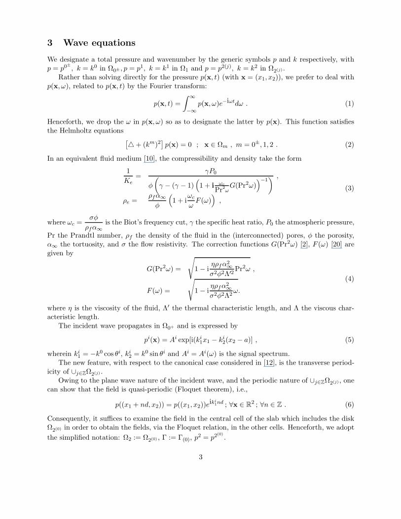
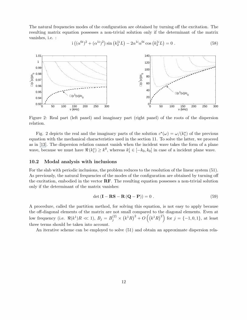
Figure 2: Real part (left panel) and imaginary part (right panel) of the roots of the dispersionrelation.
Fig. 2 depicts the real and the imaginary parts of the solution c⋆(ω) = ω/(k⋆1) of the previous
equation with the mechanical characteristics used in the section 11. To solve the latter, we proceedas in [13]. The dispersion relation cannot vanish when the incident wave takes the form of a planewave, because we must have ℜ (k⋆
1) ≥ k0, whereas ki1 ∈ [−k0, k0] in case of a incident plane wave.
10.2 Modal analysis with inclusions
For the slab with periodic inclusions, the problem reduces to the resolution of the linear system (51).As previously, the natural frequencies of the modes of the configuration are obtained by turning offthe excitation, embodied in the vector RF. The resulting equation possesses a non-trivial solutiononly if the determinant of the matrix vanishes:
det (I −RS − R (Q − P)) = 0 . (59)
A procedure, called the partition method, for solving this equation, is not easy to apply becausethe off-diagonal elements of the matrix are not small compared to the diagonal elements. Even at
low frequency (i.e. ℜ(k1)R << 1), Bj = B(2)j ×
(
k1R)2
+ O(
(
k1R)2
)
for j = −1, 0, 1, at least
three terms should be taken into account.An iterative scheme can be employed to solve (51) and obtain an approximate dispersion rela-
12

tion. We re-write this equation in the form
1 − Rl
S0 +∑
p∈Z
(Qllp − Pllp)
Bl =
Rl
∑
m∈Z
Sl−m +∑
p∈Z
(Qlmp − Plmp)
Bm (1 − δml)
+ Rl
∑
p∈Z
(
J−lpF−
1p + J+lpF+
1p
)
, ∀l ∈ Z . (60)
The iterative procedure for solving this linear set of equations is:
B(0)l = Rl
∑
p∈Z
(
J−lpF−
1p + J+lpF+
1p
)
1 − Rl
S0 +∑
p∈Z
(Qllp − Pllp)
B(n)l = Rl
1
1 − Rl
S0 +∑
p∈Z
(Qllp − Pllp)
×
∑
p∈Z
(
J−lpF−
1p + J+lpF+
1p
)
+∑
m∈Z
Sl−m +∑
p∈Z
(Qlmp − Plmp)
B(n−1)m (1 − δml)
, ∀n ∈ N∗ ,
(61)
from which it becomes apparent that the solution of B(n)l , to any order of approximation, is ex-
pressed as a fraction, the denominator of which (not depending on the order of approximation),
can become large for certain couples (k1p, ω) so as to make B(n)l , and (possibly) the field large for
these values.When this happens, a natural mode of the configuration, comprising the inclusions and the
slab, is excited, this taking the form of a resonance with respect to B(n)l , i.e. with respect to a
plane wave component of the field in the slab relative to the inclusions. As B(n)l is related to f+
1p,
f−1p, Tp and Rp, the structural resonance manifests itself for the same (k1p, ω) as concerns the field
in the slab and in the air.
1 − Rl
S0 +∑
p∈Z
(Qllp − Pllp)
= 1 − Rl
∞∑
j=1
H(1)0
(
k1jd)
2 cos(
ki1jd
)
+∑
p∈Z
2
dk12p
1(
i sin(
k12pL
)(
(
α0p
)2+
(
α1p
)2)
− 2α0pα
1p cos
(
k12pL
))
×(
cos(
k12p (a + b) + 2lθp
)
(−1)l(
(α0p)
2 − (α1p)
2)
− eik12pL
(
α0p − α1
p
)2))
= 0 . (62)
13
The latter equation is the sum of a term linked to the grating embodied in 1 − RlS0 with a termlinked to the slab embodied in −Rl
∑
p∈Z(Qllp − Pllp). This can be interpreted as a perturbation
of the dispersion relation of the gratings by the presence of the slab.
11 Numerical results
The ambiant and saturating fluid is the air medium (ρ0 = ρf = 1.213kg.m−3, c0 =
√
γP0
ρ0,
with P0 = 1.01325 × 10⁵Pa and γ = 1.4, η = 1.839 × 10⁻⁵kg.m−1.s−1). The infinite layer is1 × 10−2m thick and filled with a polymer foam M1. The radius of the inclusions is constantequal to R = 2.5 × 10⁻³m. We vary the center-to-center distance between each inclusion fromd = 1 × 10⁻²m to d = 2.5 × 10⁻²m. The inclusions are either filled with the air medium (whichdefine the so-called type 2 sample), with a melamin-foam (which define the so-called type 1 sample)or with such a material that the condition upon Γ is the Neumann one (which define the so-calledtype 3 sample).
The medium M1 is characterized by φ = 0.96, α∞ = 1.07, Λ = 273×10−6m, Λ′ = 672×10−6m,σ = 2843N.s.m−4, while the melamine-foam is characterized by φ = 0.99, α∞ = 1.001, Λ =150 × 10−6m, Λ′ = 150 × 10−6m, σ = 12 × 103N.s.m−4. The incident angle is θi = 0.
The infinite sum∑
m∈Z
over the indices of the modal representation of the diffracted field by a
cylinder is truncated as
M∑
m=−M
such that
M = int(
ℜ(
4.05 ×(
k1R)
13 + k1R
))
+ 10 . (63)
On the other hand, the infinite sum∑
p∈Z
over the indices of the k1p is found to depend on the
frequency and on the period of the grating. We also use an empirical rule we have determined by
performing a large number of numerical experiments
P∑
p=−P
such that
P =dℜ
(
k1)
2π+ 50int
e
−ω
2π50 × 103
+ 10
(
−ln
(
d
25 × 10−3
))
+ 5 . (64)
In the latter equations int (a) represents the integer part of a.The developed form of the conservation of energy relation takes the form of
1 = A + R + T , (65)
with A, R and T the absorption, hemispherical reflection and hemispherical transmission coeffi-
14
cients respectively, defined by
R =∑
p∈Z
ℜ(
k02p
)
k0i2
‖Rp(ω)‖2 =
p∑
p=−p
k02p
k0i2
‖Rp(ω)‖2 ,
T =∑
p∈Z
ℜ(
k02p
)
k0i2
‖Tp(ω)‖2 =
p∑
p=−p
k02p
k0i2
‖Tp(ω)‖2 ,
(66)
wherein p is such that
(
ki1 +
2π (p + 1)
d
)2
> (k0)2 ≥(
ki1 +
2πp
d
)2
.
15
0 50 100 150 200 250 3000
0.2
0.4
0.6
0.8
1
ν (kHz)
Abs
orpt
ion
coef
ficie
nt
Homogeneous slabd=10 × 10−3m
d=15 × 10−3m
d=20 × 10−3m
d=25 × 10−3m
0 50 100 150 200 250 3000.2
0.3
0.4
0.5
0.6
0.7
0.8
0.9
1
ν (kHz)
Tra
nsm
issi
on c
oeffi
cien
t
Homogeneous slabd=10 × 10−3m
d=15 × 10−3m
d=20 × 10−3m
d=25 × 10−3m
0 50 100 150 200 250 3000
0.2
0.4
0.6
0.8
1
ν (Hz)
Abs
orpt
ion
Coe
ffici
ent
Homogeneous slabd=10 × 10−3m
d=15 × 10−3m
d=20 × 10−3m
d=25 × 10−3m
0 50 100 150 200 250 300
0.4
0.5
0.6
0.7
0.8
0.9
1
ν (kHz)T
rans
mis
sion
coe
ffici
ent
Homogeneous slabd=10 × 10−3m
d=15 × 10−3m
d=20 × 10−3m
d=25 × 10−3m
0 50 100 150 200 250 3000
0.2
0.4
0.6
0.8
1
ν (kHz)
Abs
orpt
ion
Coe
ffice
nt
Homogeneous slabd=10 × 10−3m
d=15 × 10−3m
d=20 × 10−3m
d=25 × 10−3m
0 50 100 150 200 250 3000
0.2
0.4
0.6
0.8
1
ν (kHz)
Tra
nsm
issi
on c
oeffi
cien
t
Homogeneous slabd=10 × 10−3m
d=15 × 10−3m
d=20 × 10−3m
d=25 × 10−3m
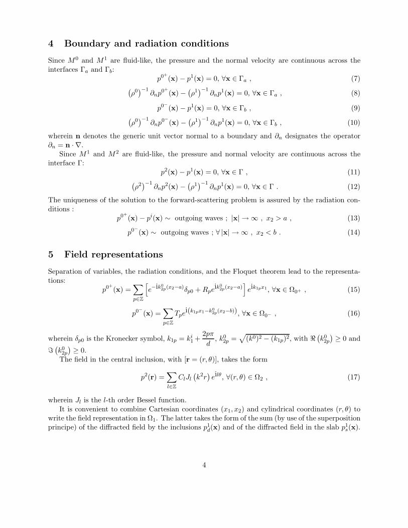
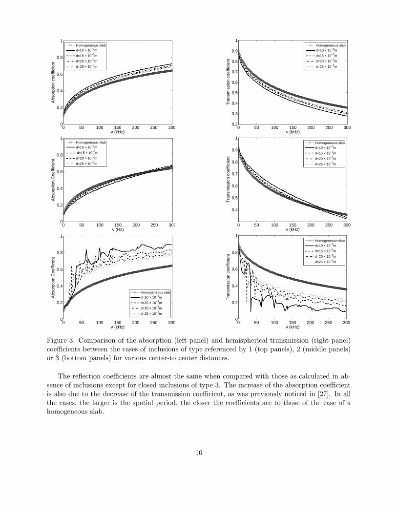
Figure 3: Comparison of the absorption (left panel) and hemispherical transmission (right panel)coefficients between the cases of inclusions of type referenced by 1 (top panels), 2 (middle panels)or 3 (bottom panels) for various center-to center distances.
The reflection coefficients are almost the same when compared with those as calculated in ab-sence of inclusions except for closed inclusions of type 3. The increase of the absorption coefficientis also due to the decrease of the transmission coefficient, as was previously noticed in [27]. In allthe cases, the larger is the spatial period, the closer the coefficients are to those of the case of ahomogeneous slab.
16
0 50 100 150 200 250 3000
0.05
0.1
0.15
0.2
0.25
0.3
0.35
ν (kHz)
Ref
lect
ion
coef
ficie
nt
Homogeneous slabd=10 × 10−3m
d=15 × 10−3m
d=20 × 10−3m
d=25 × 10−3m
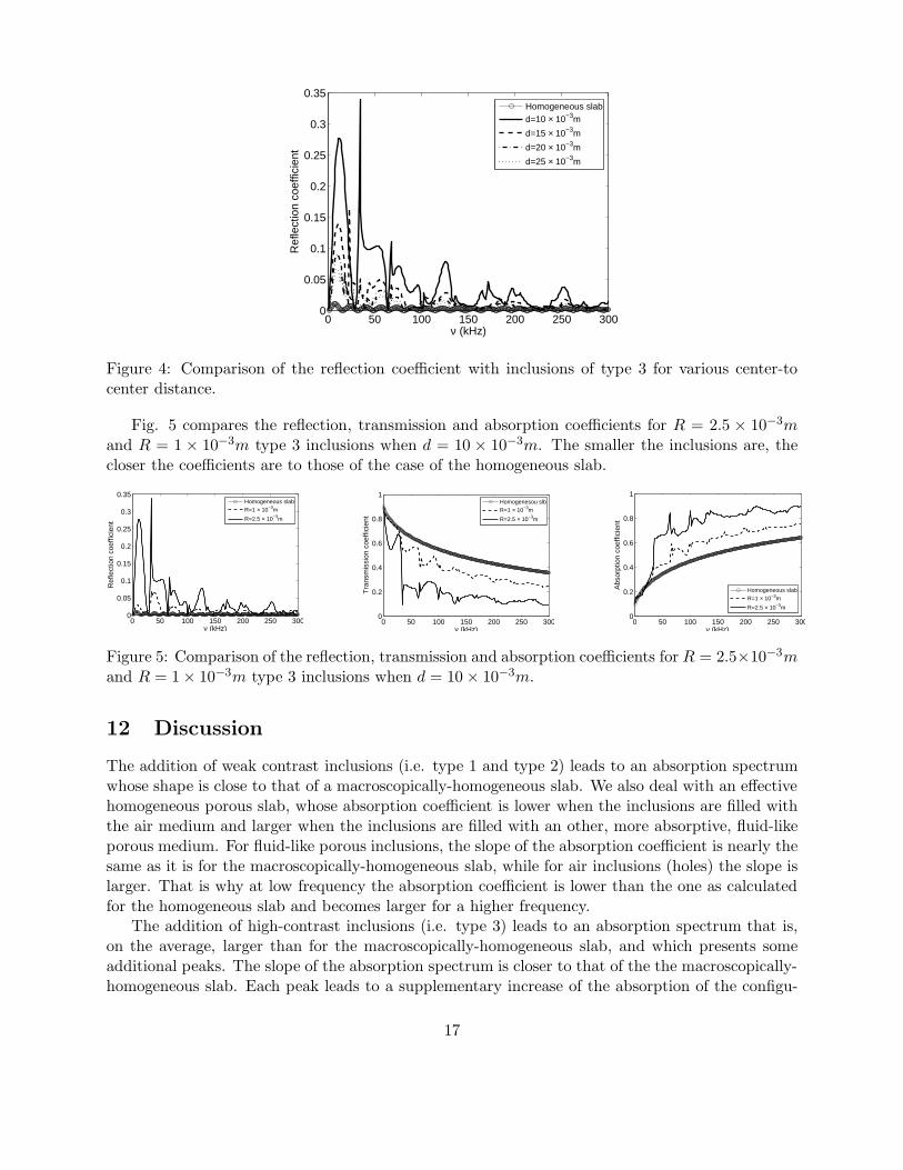
Figure 4: Comparison of the reflection coefficient with inclusions of type 3 for various center-tocenter distance.
Fig. 5 compares the reflection, transmission and absorption coefficients for R = 2.5 × 10⁻³mand R = 1 × 10⁻³m type 3 inclusions when d = 10 × 10−3m. The smaller the inclusions are, thecloser the coefficients are to those of the case of the homogeneous slab.
0 50 100 150 200 250 3000
0.05
0.1
0.15
0.2
0.25
0.3
0.35
ν (kHz)
Ref
lect
ion
coef
ficie
nt
Homogeneous slabR=1 × 10⁻³m
R=2.5 × 10⁻³m
0 50 100 150 200 250 3000
0.2
0.4
0.6
0.8
1
ν (kHz)
Tra
nsm
issi
on c
oeffi
cien
t
Homogenesou slbR=1 × 10⁻³m
R=2.5 × 10⁻³m
0 50 100 150 200 250 3000
0.2
0.4
0.6
0.8
1
Abs
orpt
ion
coef
ficie
nt
Homogeneous slabR=1 × 10⁻³m
R=2.5 × 10⁻³m
ν (kHz)
Figure 5: Comparison of the reflection, transmission and absorption coefficients for R = 2.5×10⁻³mand R = 1 × 10⁻³m type 3 inclusions when d = 10 × 10−3m.
12 Discussion
The addition of weak contrast inclusions (i.e. type 1 and type 2) leads to an absorption spectrumwhose shape is close to that of a macroscopically-homogeneous slab. We also deal with an effectivehomogeneous porous slab, whose absorption coefficient is lower when the inclusions are filled withthe air medium and larger when the inclusions are filled with an other, more absorptive, fluid-likeporous medium. For fluid-like porous inclusions, the slope of the absorption coefficient is nearly thesame as it is for the macroscopically-homogeneous slab, while for air inclusions (holes) the slope islarger. That is why at low frequency the absorption coefficient is lower than the one as calculatedfor the homogeneous slab and becomes larger for a higher frequency.
The addition of high-contrast inclusions (i.e. type 3) leads to an absorption spectrum that is,on the average, larger than for the macroscopically-homogeneous slab, and which presents someadditional peaks. The slope of the absorption spectrum is closer to that of the the macroscopically-homogeneous slab. Each peak leads to a supplementary increase of the absorption of the configu-
17
ration. The absorption can be multiplied by a factor of three at the location of some of these peakswhen compared with the one of the macroscopically-homogeneous slab. Two types of peaks aredistinguished. Each of them appears periodically for a specific period of the inclusions and can beassociated with mode excitation of the whole configuration.
Two peaks stand out for all center-to-center distances at the same frequencies near ν = 65kHz,ν = 133kHz. This corresponds to the excitation of quasi-mode 2 and 3 of the initial slab . Aquasi-mode is a mode of the global configuration whose structure is close to the one of a mode of asub-structure it is composed of. Quasi-mode 1 occurs for a frequency too low for it to be seen, andquasi-mode 3 is largely attenuated. The excitation of the quasi-mode of the slab is made possibleby the spatial periodicity of the configuration.
In the absence of the inclusions, the modes of a homogeneous slab filled with a fluid-like porousmedium cannot be excited by an incident plane wave propagating in the air [15]. If det(E) = 0denotes a generic dispersion relation, then we can say that det(E) is close to zero (vanishes inabsence of dissipation) only for an evanescent wave in the air medium, which cannot be excited byan incident plane bulk wave.
The spatially-periodic configuration leads to a field representation, through the Floquet the-orem, that includes evanescent waves the air medium. Another explanation of the quasi-modeexcitation relies on the fact that each inclusion acts as an induced cylindrical source. The re-sponse of an active cylindrical source radiating in the neighborhood of a homogeneous slab (see[12]) enables a mode of this slab to be excited because some of the waves radiated by the source areevanescent and have the same structure (at resonance) as that of the evanescent wave associatedwith the mode.
The other peaks appear in a periodic manner beyond the peak relative to the quasi-mode ofthe slab. Their periodicity is inversely proportional to the spatial periodicity d of the grating. Thisphenomena was already encountered in [14] and was attributed to a periodization of the quasi-mode
due to the primitive reciprocal lattice vector k1 =2π
di1. This periodization is strongly associated
with the excitation of quasi Cutler-modes.The increase of the absorption is also due to an average (global) increase which does not take
the form of additional peaks. This global increase can be explained by multipathing between eachinclusion and/or by excitation of evanescent waves in the slab, thanks to the existence of the grating.
Addition of high contrast inclusions also leads to an increase of the absorption of the slab, largelyassociated with a decrease of the transmission coefficient. This is mainly due to mode excitationof the whole configuration, whose structure consists of evanescent waves in the air medium (andin the slab), thus leading to an entrapment of the energy in the slab. The latter is dissipated bythermal and viscous effects.
In all the cases, the closer the inclusions are, and/or the larger are their radii, the larger is theabsorption.
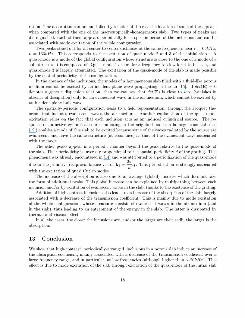
13 Conclusion
We show that high-contrast, periodically-arranged, inclusions in a porous slab induce an increase ofthe absorption coefficient, mainly associated with a decrease of the transmission coefficient over alarge frequency range, and in particular, at low frequencies (although higher than ∼ 20kHz). Thiseffect is due to mode excitation of the slab through excitation of the quasi-mode of the initial slab
18
(enabled) by the periodic inclusions, and to excitation of grating modes via multipathing betweenthe inclusions.
This increase of absorption is most noticeable for rigid frame porous inclusions in a large portionof the frequency range, and is less pronounced for air inclusions.
The reflection coefficients are found to be of the same order as those in the absence of inclusionsfor low-contrast inclusions, and to be higher than those in the absence of inclusions for high contrastinclusions. The way of reducing the reflection is by acting on the surface geometry of the slab. Afirst approach can consist in the addition of a homogenized layer of double porosity [24].
Acknowledgment
The authors are garteful to D. Lesselier for his useful comments on earlier version of this paper.
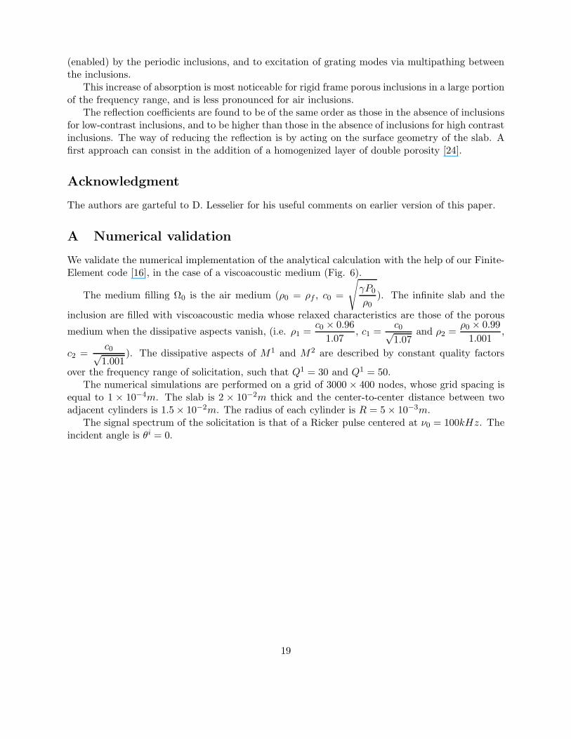
A Numerical validation
We validate the numerical implementation of the analytical calculation with the help of our Finite-Element code [16], in the case of a viscoacoustic medium (Fig. 6).
The medium filling Ω0 is the air medium (ρ0 = ρf , c0 =
√
γP0
ρ0). The infinite slab and the
inclusion are filled with viscoacoustic media whose relaxed characteristics are those of the porous
medium when the dissipative aspects vanish, (i.e. ρ1 =c0 × 0.96
1.07, c1 =
c0√1.07
and ρ2 =ρ0 × 0.99
1.001,
c2 =c0√1.001
). The dissipative aspects of M1 and M2 are described by constant quality factors
over the frequency range of solicitation, such that Q1 = 30 and Q1 = 50.The numerical simulations are performed on a grid of 3000 × 400 nodes, whose grid spacing is
equal to 1 × 10⁻⁴m. The slab is 2 × 10⁻²m thick and the center-to-center distance between twoadjacent cylinders is 1.5 × 10⁻²m. The radius of each cylinder is R = 5 × 10⁻³m.
The signal spectrum of the solicitation is that of a Ricker pulse centered at ν0 = 100kHz. Theincident angle is θi = 0.
19
100 200 300 400 500
−0.06
−0.04
−0.02
0
0.02
0.04
t (µ s)
pR((
0m,1
.5 ×
10−
2 m),
t) (
a.u.
)
Semi−analytical resultsNumerical results
100 200 300 400 500
−0.06
−0.04
−0.02
0
0.02
0.04
t (µ s)
pR((
dm,1
.5 ×
10−
2 m),
t) (
a.u.
)
Semi−analtical resultsNumerical results
100 200 300 400 500
−0.6
−0.4
−0.2
0
0.2
0.4
t (µ s)
pT((
0m,−
1.5
× 10
−2 m
),t)
(a.
u.)
Semi−analytical resultsNumerical results
100 200 300 400 500
−0.6
−0.4
−0.2
0
0.2
0.4
t (µ s)
Semi−analytical resultsNumerical results
pT((
dm,−
1.5
× 10
−2 m
),t)
(a.
u.)
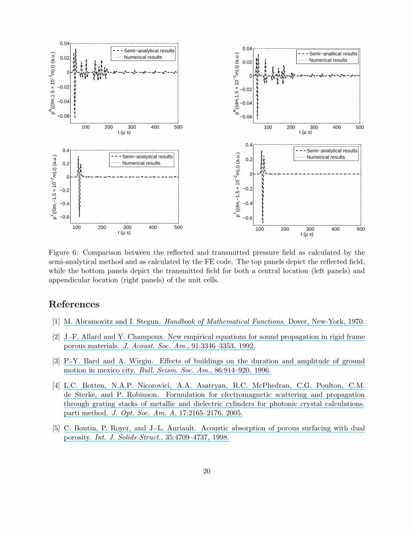
Figure 6: Comparison between the reflected and transmitted pressure field as calculated by thesemi-analytical method and as calculated by the FE code. The top panels depict the reflected field,while the bottom panels depict the transmitted field for both a central location (left panels) andappendicular location (right panels) of the unit cells.
References
[1] M. Abramovitz and I. Stegun. Handbook of Mathematical Functions. Dover, New-York, 1970.
[2] J.-F. Allard and Y. Champoux. New empirical equations for sound propagation in rigid frameporous materials. J. Acoust. Soc. Am., 91:3346–3353, 1992.
[3] P.-Y. Bard and A. Wirgin. Effects of buildings on the duration and amplitude of groundmotion in mexico city. Bull. Seism. Soc. Am., 86:914–920, 1996.
[4] L.C. Botten, N.A.P. Nicorovici, A.A. Asatryan, R.C. McPhedran, C.G. Poulton, C.M.de Sterke, and P. Robinson. Formulation for electromagnetic scattering and propagationthrough grating stacks of metallic and dielectric cylinders for photonic crystal calculations.parti method. J. Opt. Soc. Am. A, 17:2165–2176, 2005.
[5] C. Boutin, P. Royer, and J.-L. Auriault. Acoustic absorption of porous surfacing with dualporosity. Int. J. Solids Struct., 35:4709–4737, 1998.
20
[6] B. Budiansky. On the elastic moduli of some heterogeneous materials. J. Mech. Phys. Solids,13:223–227, 1965.
[7] Cutler C.C. Technical Report MM 44-160-218, Bell Telephone Lab, 1944.
[8] J.J. Cuomo, J.F. Ziegler, and J.M. Woodhall. A new concept for solar energy thermal conver-sion. Appl. Phys. Let., 26:557–559, 1992.
[9] A. de Bruijn. Anomalous effects in the sound absorption of periodically uneven surfaces.Acustica, 24:75–84, 1971.
[10] L. De Ryck, J.P. Groby, Ph. Leclaire, W. Lauriks, A. Wirgin, C. Depollier, and Z.E.A. Fellah.Acoustic wave propagation in a macroscopically inhomogeneous porous medium saturated bya fluid. Appl. Phys. Lett., 90:181901, 2007.
[11] D. Felbacq, G. Tayeb, and D. Mayster. Scattering by a random set of parallel cylinders. J.
Opt. Soc. Am. A, 11:2526–2538, 1994.
[12] J.-P. Groby, L. De Ryck, P. Leclaire, A. Wirgin, W. Lauriks, Gilbert R.P., and Y.S. Xu. Useof specific Green’s functions for solving direct problems involving a heterogeneous rigid frameporous medium slab solicited by the acoustic waves. Math. Meth. Appl. Sci., 30:91–122, 2007.
[13] J.-P. Groby and A. Wirgin. 2D ground motion at a soft viscoelastic layer/hard substratumsite in response to SH cylindrical waves radiated by deep and shallow line sources: Numericalresults. Geophys. J. Intl., 163:192–224, 2005.
[14] J.-P. Groby and A. Wirgin. Seismic motion in urban sites consisting of blocks in welded contactwith a soft layer overlying a hard half space. 2007. submitted to Geophys. J. Intl.
[15] J.P. Groby, E. Ogam, A. Wirgin, Z.E.A. Fellah, W. Lauriks, J.-Y. Chapelon, C. Depollier,L. De Ryck, R. Gilbert, N. Sebaa, and Y. Xu. 2D mode excitation in a porous slab saturatedwith air in the high frequency approximation. In Symposium on the Acoustics of Poro-Elastic
Materials, pages 53–60, ENTPE, Lyon, France, December 2005.
[16] J.P. Groby and C. Tsogka. A time domain method for modeling viscoacoustic wave propaga-tion. J. Compt. Acoust., 14:201–236, 2006.
[17] Z. Hashin and S. Shtrikman. A variational approach to the theory of the elastic behaviour ofmultiphase materials. J. Mech. Phys. Solids, 11:127–140, 1963.
[18] C.M. Horwitz. Solar-selective globular metal films. J. Opt. Soc. Am., 68:1032–1038, 1978.
[19] J.D. Joannopoulos, R.D. Meade, and J.N. Winn. Photonic Crystals; Molding the Flow of
Light. Princeton University Press, Princeton, 1995.
[20] D.J. Johnson, J. Koplik, and Dashen R. Theory of dynamic permeability and tortuosity influid-saturated porous media. J. Fluid Mech., 176:379–402, 1987.
[21] L. Kelders, J.-F. Allard, and W. Lauriks. Ultrasonic surface waves above rectangular-groovegratings. J. Acoust. Soc. Am., 103(5):2730–2733, 1998.
21

[22] A. Khelif, B. Djafari-Rouhani, V. Laude, and M. Solal. Coupling characteristics of localizedphonons in photonic crystal fibers. J. Appl. Phys., 94(12):7944–7946, 2003.
[23] V. Laude, M. Wilm, S. Benchabane, and A. Khelif. Full band gap for surface acoustic wavesin a piezoelectric phononic crystal. Phys. Rev. E, 71:036607, 2003.
[24] X. Olny and C. Boutin. Acoustic wave propagation in double porosity media. J. Acoust. Soc.
Am., 113:73–89, 2003.
[25] B. Sapoval, B. Hebert, and S. Russ. Experimental study of a fractal acoustical cavity. J.
Acoust. Soc. Am., 105:2014–2019, 1999.
[26] J.B Tanneau, O. amd Casimir and P. Lamary. Optimization of multilayered panels with poroe-lastic components for an acoustical transmission objective. J. Acoust. Soc. Am., 120(3):1227–1238, 2006.
[27] V. Tournat, V. Pagneux, D. Lafarge, and L. Jaouen. Multiple scattering of acoustic waves andporous absorbing media. Phys. Rev. E., 70:026609, 2004.
[28] V.G. Veselago. The electrodynamics of substances with simultaneous negative value of e andm. Sov. Phys. Usp., 10:509–514, 1968.
[29] S. Wilcox, L.C. Botten, R.C. McPhedran, C.G. Poulton, and C.M. de Sterke. Modeling ofdefect modes in photonic crystals using the fictitious source superposition method. Phys. Rev.
E, 71:056606, 2005.
[30] M. Wilm, K. Khelif, S. Ballandras, V. Laude, and B. Djafari-Rouhani. Out-of-plane propa-gation of elastic waves in two-dimensional phononic band-gap material. Phys. Rev. E, page065602, 2003.
[31] R.W. Wood. A suspected case of the electrical resonance of minute metal particles for light-waves. a new type of absorption. Philosophical Magazine and Journal of Science, 4:369, 1902.
[32] T.T. Wu. The effect of inclusion shape on the elastic moduli of the two-phase material. Int.
J. Solids Struct., 1:1–8, 1966.
[33] E. Yablonovitch. Photonic band-gap structures. J. Opt. Soc. Am. B, 10(2):283–295, 1993.
22
Related Documents


