DESIGN GUIDE A COUSTIC Insulation Design Guide ACOUSTIC

Welcome message from author
This document is posted to help you gain knowledge. Please leave a comment to let me know what you think about it! Share it to your friends and learn new things together.
Transcript
D E S I G N G U I D E
AC
OU
ST
IC
I n s u l a t i o n D e s i g n G u i d e
ACOUSTIC
A C O U S T I C D E S I G N G U I D E
C S R B R A D F O R D I N S U L A T I O N2
Introduction 2
Product Range, Applications & Selection Guides 3 – 13
Bradford Acoustic Solutions
Party & Interior Walls Residential & Commercial 14
External Walls 18Roof/Ceiling Systems 18Floor/Ceiling Systems 23Floors 24Plumbing 25Gutters & Downpipes 26Pipes, Tanks & Vessels 27Factories & Workshops 27Acoustic Baffles 29Acoustic Enclosures 30Vibration Damping 34Air Conditioning Systems 36
Bradford Acoustic Solutions for Specialty Applications
Home Cinema 46Auditoriums 47Sports Complexes 48Canteens/Restaurants 50Karaoke/Night Clubs 50Shopping Centres 51Recording Studios 52Heavy Plant 53OEM Application 53
Appendix A The Nature of Sound 54Sound Transmission 57Flanking Paths 59Sound Absorption 59Reverberation 61Room Acoustics 64Industrial Acoustics 67Speech Privacy 68
Appendix B Floor/Ceiling Systems 69 – 70
Appendix C Product Data 71Sound Absorption Coefficients 74Static Insertion Loss/Silencers 77Air Flow Resistivity 78
Appendix D Terminology 79
CSR Bradford InsulationRegional Contact Details 80
Contents. Introduction.The Bradford Insulation Group forms part of the
Building Materials Division of CSR Limited. CSRBradford Insulation manufactures and markets anextensive range of insulation products offering outstandingthermal, acoustic and fire protection properties for use inall types of domestic and commercial buildings.
Two mineral fibre insulation types are available;‘Bradford Glasswool’, which is manufactured bycontrolled felting of biosoluble glass wool bonded witha thermosetting resin; and ‘Bradford Fibertex™ Rockwool’which is spun from natural rock and bonded with athermosetting resin. Both are available in sheet or rollform and as moulded pipe insulation.
Bradford Thermofoil™ and Thermotuff™ are a rangeof aluminium foil laminates available in various grades.
All CSR Bradford Insulation products are tested tomeet stringent quality control standards incorporatingquality management systems such as AS3902/ISO9002.
ABOUT THIS GUIDE.The purpose of this guide is to provide information on the
technical benefits obtained with the inclusion of acousticinsulation materials in the construction of all types of buildingsas well as noise control of machinery.
The range of Bradford products and their applicationsis presented along with data and worked examples toillustrate design considerations.
This Acoustic Design Guide also outlines the basicproperties of sound, and methods for its control. It does notset out to provide a definitive solution to every conceivablenoise problem. Rather, it aims to explain the principlesinvolved, so that these principles can be applied along withcommon sense, to overcome common acoustic problems.
Acoustics is however a complex science, and there willbe many instances where the services of specialist acousticconsultants or noise control engineers are indispensable.The reader is cautioned against investing large sums ofmoney in noise control without first seeking advice.This is particularly pertinent where compliance withnoise abatement orders is concerned.
TECHNICAL ASSISTANCE.To assist designers, a free and comprehensive technical
service, as well as advice and assistance in specifying and usingBradford products is available from CSR Bradford Insulationoffices in your region. Further technical data and productupdates are also available on the CSR Building SolutionsWebsite: www.csr.com.au/bradford
Information included in this Design Guide relates toproducts as manufactured at the date of publication. Asthe CSR Bradford Insulation policy is one of continualproduct improvement, technical details as published aresubject to change without notice.
Contents.
A C O U S T I C D E S I G N G U I D E
C S R B R A D F O R D I N S U L A T I O N3
The Importance of Acoustic Insulation.
The minimisation of noise has become a significant environmental issue in the modern world,whether at home, at work or on holidays.
CSR Bradford Insulation manufacturers and distributes an extensive range of insulation productsthat provide excellent noise control properties, as well as the traditional thermal and fire controlbenefits.
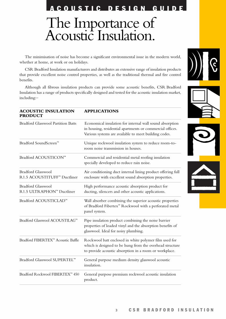
Although all fibrous insulation products can provide some acoustic benefits, CSR BradfordInsulation has a range of products specifically designed and tested for the acoustic insulation market,including:–
ACOUSTIC INSULATIONPRODUCT
Bradford Glasswool Partition Batts
Bradford SoundScreen™
Bradford ACOUSTICON™
Bradford GlasswoolR1.5 ACOUSTITUFF™ Ductliner
Bradford GlasswoolR1.5 ULTRAPHON™ Ductliner
Bradford ACOUSTICLAD™
Bradford Glasswool ACOUSTILAG™
Bradford FIBERTEX™ Acoustic Baffle
Bradford Glasswool SUPERTEL™
Bradford Rockwool FIBERTEX™ 450
APPLICATIONS
Economical insulation for internal wall sound absorptionin housing, residential apartments or commercial offices.Various systems are available to meet building codes.
Unique rockwool insulation system to reduce room-to-room noise transmission in houses.
Commercial and residential metal roofing insulationspecially developed to reduce rain noise.
Air conditioning duct internal lining product offering fullenclosure with excellent sound absorption properties.
High performance acoustic absorption product forducting, silencers and other acoustic applications.
Wall absorber combining the superior acoustic propertiesof Bradford Fibertex™ Rockwool with a perforated metalpanel system.
Pipe insulation product combining the noise barrierproperties of loaded vinyl and the absorption benefits ofglasswool. Ideal for noisy plumbing.
Rockwool batt enclosed in white polymer film used forwhich is designed to be hung from the overhead structureto provide acoustic absorption in a room or workplace.
General purpose medium density glasswool acousticinsulation.
General purpose premium rockwool acoustic insulationproduct.
A C O U S T I C D E S I G N G U I D E
C S R B R A D F O R D I N S U L A T I O N4
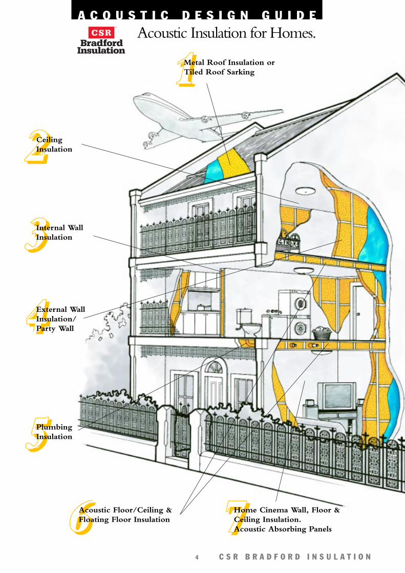
1111Metal Roof Insulation orTiled Roof Sarking
2222CeilingInsulation
4444External WallInsulation/Party Wall
5555PlumbingInsulation
7777Home Cinema Wall, Floor &Ceiling Insulation.Acoustic Absorbing Panels
3333Internal WallInsulation
6666Acoustic Floor/Ceiling &Floating Floor Insulation
Acoustic Insulation for Homes.

A C O U S T I C D E S I G N G U I D E
C S R B R A D F O R D I N S U L A T I O N5
2222 Ceiling
Tiled Roof Sarking
6666 AcousticFloor/Ceilings
Floating Floors
7777 Home Cinema
5555 Plumbing
1111 Metal Roofing
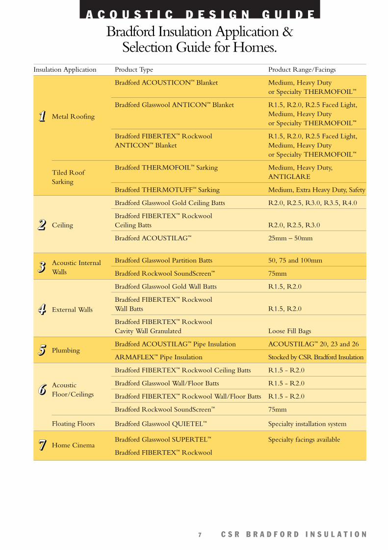
Bradford Insulation Application & Selection Guide for Homes.
Insulation Application Product Type Product Range/Facings
Bradford ACOUSTICON™ Blanket Medium, Heavy Dutyor Specialty THERMOFOIL™
Bradford Glasswool ANTICON™ Blanket R1.5, R2.0, R2.5 Faced Light,Medium, Heavy Dutyor Specialty THERMOFOIL™
Bradford FIBERTEX™ Rockwool R1.5, R2.0, R2.5 Faced Light,ANTICON™ Blanket Medium, Heavy Duty
or Specialty THERMOFOIL™
Bradford THERMOFOIL™ Sarking Medium, Heavy Duty,ANTIGLARE
Bradford THERMOTUFF™ Sarking Medium, Extra Heavy Duty, Safety
Bradford Glasswool Gold Ceiling Batts R2.0, R2.5, R3.0, R3.5, R4.0
Bradford FIBERTEX™ Rockwool Ceiling Batts R2.0, R2.5, R3.0
Bradford ACOUSTILAG™ 2.5 - 5.0mmLoose Fill Bags
Bradford Glasswool Partition Batts 50, 75 and 100mm
Bradford Rockwool SoundScreen™ 75mm
Bradford Glasswool Gold Wall Batts R1.5, R2.0
Bradford FIBERTEX™ Rockwool Wall Batts R1.5, R2.0
Bradford FIBERTEX™ Rockwool Cavity Wall Granulated Loose Fill Bags
Bradford ACOUSTILAG™ Pipe Insulation ACOUSTILAG™ 20, 23 and 26
Bradford HANDITUBE™ Pipe Insulation Stocked by CSR Bradford Insulation
Bradford FIBERTEX™ Rockwool Ceiling Batts R1.5 - R2.0
Bradford Glasswool Wall/Floor Batts R1.5 - R2.0
Bradford FIBERTEX™ Rockwool Wall/Floor Batts R1.5 - R2.0
Bradford Rockwool SoundScreen™ 75mm
Bradford Glasswool QUIETEL™ Specialty installation system
Bradford Glasswool SUPERTEL™ Specialty facings available
Bradford FIBERTEX™ Rockwool
3333 Acoustic InternalWalls
4444 External Walls
A C O U S T I C D E S I G N G U I D E
C S R B R A D F O R D I N S U L A T I O N6
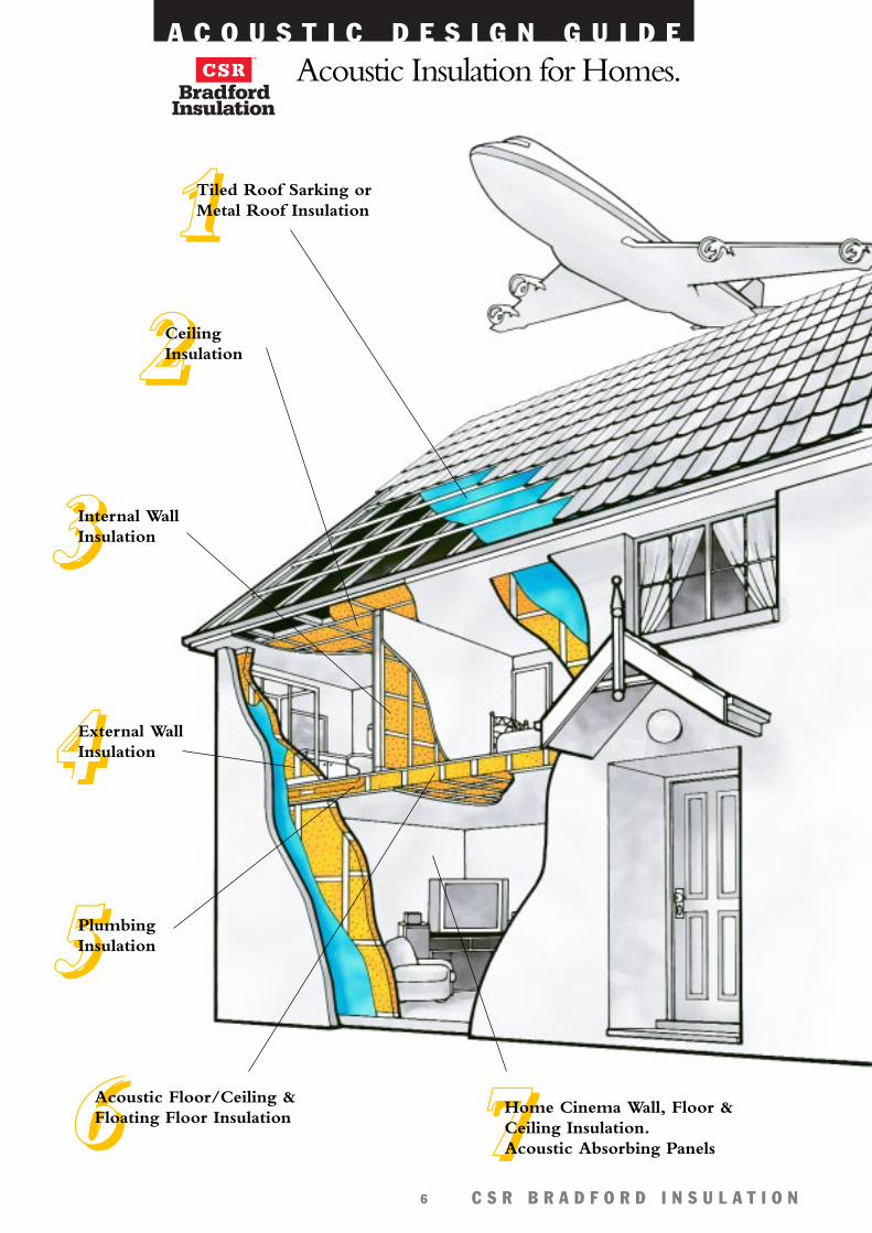
7777Home Cinema Wall, Floor &Ceiling Insulation.Acoustic Absorbing Panels
Acoustic Insulation for Homes.
1111Tiled Roof Sarking orMetal Roof Insulation
2222CeilingInsulation
4444External WallInsulation
5555PlumbingInsulation
3333Internal WallInsulation
6666Acoustic Floor/Ceiling &Floating Floor Insulation
A C O U S T I C D E S I G N G U I D E
C S R B R A D F O R D I N S U L A T I O N7
2222 Ceiling
Tiled Roof Sarking
6666 AcousticFloor/Ceilings
Floating Floors
7777 Home Cinema
5555 Plumbing
1111 Metal Roofing
Bradford Insulation Application & Selection Guide for Homes.
Insulation Application Product Type Product Range/Facings
Bradford ACOUSTICON™ Blanket Medium, Heavy Dutyor Specialty THERMOFOIL™
Bradford Glasswool ANTICON™ Blanket R1.5, R2.0, R2.5 Faced Light,Medium, Heavy Dutyor Specialty THERMOFOIL™
Bradford FIBERTEX™ Rockwool R1.5, R2.0, R2.5 Faced Light,ANTICON™ Blanket Medium, Heavy Duty
or Specialty THERMOFOIL™
Bradford THERMOFOIL™ Sarking Medium, Heavy Duty,ANTIGLARE
Bradford THERMOTUFF™ Sarking Medium, Extra Heavy Duty, Safety
Bradford Glasswool Gold Ceiling Batts R2.0, R2.5, R3.0, R3.5, R4.0
Bradford FIBERTEX™ Rockwool Ceiling Batts R2.0, R2.5, R3.0
Bradford ACOUSTILAG™ 25mm – 50mm
Bradford Glasswool Partition Batts 50, 75 and 100mm
Bradford Rockwool SoundScreen™ 75mm
Bradford Glasswool Gold Wall Batts R1.5, R2.0
Bradford FIBERTEX™ Rockwool Wall Batts R1.5, R2.0
Bradford FIBERTEX™ Rockwool Cavity Wall Granulated Loose Fill Bags
Bradford ACOUSTILAG™ Pipe Insulation ACOUSTILAG™ 20, 23 and 26
ARMAFLEX™ Pipe Insulation Stocked by CSR Bradford Insulation
Bradford FIBERTEX™ Rockwool Ceiling Batts R1.5 - R2.0
Bradford Glasswool Wall/Floor Batts R1.5 - R2.0
Bradford FIBERTEX™ Rockwool Wall/Floor Batts R1.5 - R2.0
Bradford Rockwool SoundScreen™ 75mm
Bradford Glasswool QUIETEL™ Specialty installation system
Bradford Glasswool SUPERTEL™ Specialty facings available
Bradford FIBERTEX™ Rockwool
3333 Acoustic InternalWalls
4444 External Walls
A C O U S T I C D E S I G N G U I D E
C S R B R A D F O R D I N S U L A T I O N8
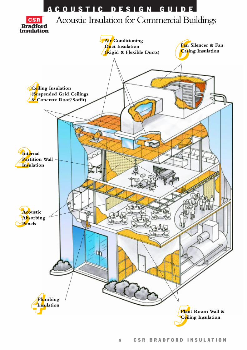
Acoustic Insulation for Commercial Buildings
1111Ceiling Insulation(Suspended Grid Ceilings& Concrete Roof/Soffit)
2222InternalPartition Wall Insulation
3333AcousticAbsorbingPanels
4444Plumbing Insulation
5555Plant Room Wall &Ceiling Insulation
6666Fan Silencer & FanCasing Insulation 7777Air Conditioning
Duct Insulation (Rigid & Flexible Ducts)
A C O U S T I C D E S I G N G U I D E
C S R B R A D F O R D I N S U L A T I O N9
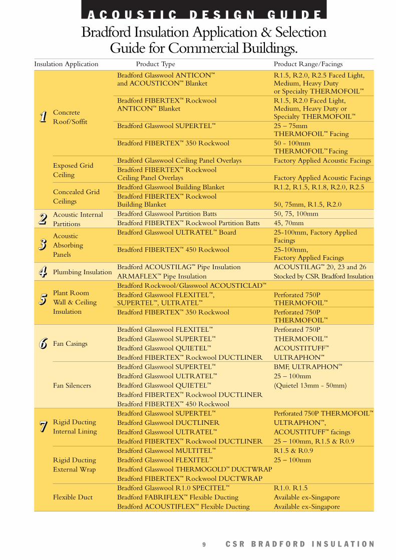
Insulation Application Product Type Product Range/Facings
Bradford Glasswool ANTICON™ R1.5, R2.0, R2.5 Faced Light,and ACOUSTICON™ Blanket Medium, Heavy Duty
or Specialty THERMOFOIL™
Bradford FIBERTEX™ Rockwool R1.5, R2.0 Faced Light,ANTICON™ Blanket Medium, Heavy Duty or
Specialty THERMOFOIL™
Bradford Glasswool SUPERTEL™ 25 – 75mm THERMOFOIL™ Facing
Bradford FIBERTEX™ 350 Rockwool 50 - 100mm THERMOFOIL™ Facing
Bradford Glasswool Ceiling Panel Overlays Factory Applied Acoustic FacingsBradford FIBERTEX™ Rockwool Ceiling Panel Overlays Factory Applied Acoustic FacingsBradford Glasswool Building Blanket R1.2, R1.5, R1.8, R2.0, R2.5Bradford FIBERTEX™ Rockwool Building Blanket 50, 75mm, R1.5, R2.0Bradford Glasswool Partition Batts 50, 75, 100mmBradford FIBERTEX™ Rockwool Partition Batts 45, 70mmBradford Glasswool ULTRATEL™ Board 25-100mm, Factory Applied
FacingsBradford FIBERTEX™ 450 Rockwool 25-100mm,
Factory Applied FacingsBradford ACOUSTILAG™ Pipe Insulation ACOUSTILAG™ 20, 23 and 26ARMAFLEX™ Pipe Insulation Stocked by CSR Bradford InsulationBradford Rockwool/Glasswool ACOUSTICLAD™
Bradford Glasswool FLEXITEL™, Perforated 750P SUPERTEL™, ULTRATEL™ THERMOFOIL™
Bradford FIBERTEX™ 350 Rockwool Perforated 750P THERMOFOIL™
Bradford Glasswool FLEXITEL™ Perforated 750PBradford Glasswool SUPERTEL™ THERMOFOIL™
Bradford Glasswool QUIETEL™ ACOUSTITUFF™
Bradford FIBERTEX™ Rockwool DUCTLINER ULTRAPHON™
Bradford Glasswool SUPERTEL™ BMF, ULTRAPHON™
Bradford Glasswool ULTRATEL™ 25 – 100mmBradford Glasswool QUIETEL™ (Quietel 13mm - 50mm)Bradford FIBERTEX™ Rockwool DUCTLINERBradford FIBERTEX™ 450 RockwoolBradford Glasswool SUPERTEL™ Perforated 750P THERMOFOIL™
Bradford Glasswool DUCTLINER ULTRAPHON™,Bradford Glasswool ULTRATEL™ ACOUSTITUFF™ facingsBradford FIBERTEX™ Rockwool DUCTLINER 25 – 100mm, R1.5 & R0.9Bradford Glasswool MULTITEL™ R1.5 & R0.9Bradford Glasswool FLEXITEL™ 25 – 100mmBradford Glasswool THERMOGOLD™ DUCTWRAPBradford FIBERTEX™ Rockwool DUCTWRAPBradford Glasswool R1.0 SPECITEL™ R1.0. R1.5Bradford FABRIFLEX™ Flexible Ducting Available ex-SingaporeBradford ACOUSTIFLEX™ Flexible Ducting Available ex-Singapore
Bradford Insulation Application & Selection Guide for Commercial Buildings.
1111 Concrete Roof/Soffit
Exposed Grid Ceiling
Concealed GridCeilings
2222 Acoustic InternalPartitions
7777 Rigid DuctingInternal Lining
4444 Plumbing Insulation
Rigid DuctingExternal Wrap
Flexible Duct
5555Plant RoomWall & CeilingInsulation
6666 Fan Casings
Fan Silencers
3333Acoustic AbsorbingPanels
A C O U S T I C D E S I G N G U I D E
C S R B R A D F O R D I N S U L A T I O N10
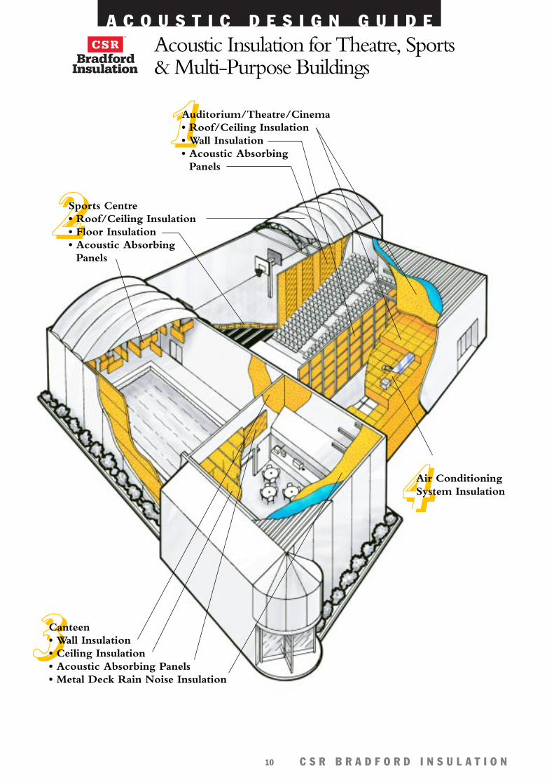
Acoustic Insulation for Theatre, Sports & Multi-Purpose Buildings
2222Sports Centre• Roof/Ceiling Insulation• Floor Insulation• Acoustic Absorbing
Panels
3333Canteen• Wall Insulation• Ceiling Insulation• Acoustic Absorbing Panels• Metal Deck Rain Noise Insulation
1111Auditorium/Theatre/Cinema • Roof/Ceiling Insulation• Wall Insulation• Acoustic Absorbing
Panels
4444Air ConditioningSystem Insulation
A C O U S T I C D E S I G N G U I D E
C S R B R A D F O R D I N S U L A T I O N11
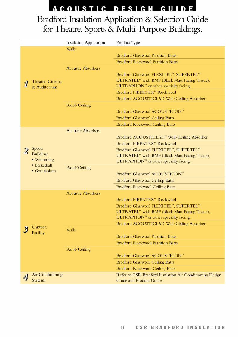
Insulation Application Product Type
Walls
Bradford Glasswool Partition Batts
Bradford Rockwool Partition Batts
Acoustic Absorbers
Bradford Glasswool FLEXITEL™, SUPERTEL™
ULTRATEL™ with BMF (Black Matt Facing Tissue),ULTRAPHON™ or other specialty facing.
Bradford FIBERTEX™ Rockwool
Bradford ACOUSTICLAD Wall/Ceiling Absorber
Roof/Ceiling
Bradford Glasswool ACOUSTICON™
Bradford Glasswool Ceiling Batts
Bradford Rockwool Ceiling Batts
Acoustic Absorbers
Bradford ACOUSTICLAD™ Wall/Ceiling Absorber
Bradford FIBERTEX™ Rockwool
Bradford Glasswool FLEXITEL™, SUPERTEL™
ULTRATEL™ with BMF (Black Matt Facing Tissue),ULTRAPHON™ or other specialty facing.
Roof/Ceiling
Bradford Glasswool ACOUSTICON™
Bradford Glasswool Ceiling Batts
Bradford Rockwool Ceiling Batts
Acoustic Absorbers
Bradford FIBERTEX™ Rockwool
Bradford Glasswool FLEXITEL™, SUPERTEL™
ULTRATEL™ with BMF (Black Matt Facing Tissue),ULTRAPHON™ or other specialty facing.
Bradford ACOUSTICLAD Wall/Ceiling Absorber
Walls
Bradford Glasswool Partition Batts
Bradford Rockwool Partition Batts
Roof/Ceiling
Bradford Glasswool ACOUSTICON™
Bradford Glasswool Ceiling Batts
Bradford Rockwool Ceiling Batts
Refer to CSR Bradford Insulation Air Conditioning DesignGuide and Product Guide.
2222 SportsBuildings• Swimming • Basketball• Gymnasium
3333 CanteenFacility
1111 Theatre, Cinema& Auditorium
4444 Air ConditioningSystems
Bradford Insulation Application & Selection Guidefor Theatre, Sports & Multi-Purpose Buildings.
A C O U S T I C D E S I G N G U I D E
C S R B R A D F O R D I N S U L A T I O N12
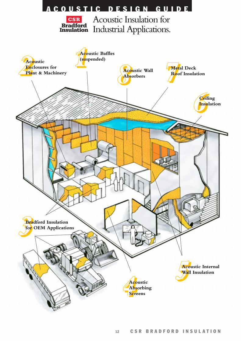
Acoustic Insulation forIndustrial Applications.
6666CeilingInsulation
1111Acoustic Baffles(suspended)
8888Acoustic WallAbsorbers 7777Metal Deck
Roof Insulation
4444AcousticAbsorbingScreens
5555Acoustic InternalWall Insulation
3333Bradford Insulationfor OEM Applications
2222AcousticEnclosures forPlant & Machinery
A C O U S T I C D E S I G N G U I D E
C S R B R A D F O R D I N S U L A T I O N13
3333 OEM Applications
2222 Acoustic Enclosuresfor Plant & Machinery
4444 AcousticAbsorbing Screens
7777 Metal DeckRoofs
8888 Acoustic WallAbsorbers
6666 Ceilings
1111 Acoustic Baffles
5555 Acoustic InternalWalls
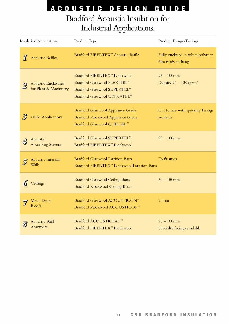
Bradford Acoustic Insulation for Industrial Applications.
Insulation Application Product Type Product Range/Facings
Bradford FIBERTEX™ Acoustic Baffle Fully enclosed in white polymer
film ready to hang.
Bradford FIBERTEX™ Rockwool 25 – 100mm
Bradford Glasswool FLEXITEL™ Density 24 – 120kg/m3
Bradford Glasswool SUPERTEL™
Bradford Glasswool ULTRATEL™
Bradford Glasswool Appliance Grade Cut to size with specialty facings
Bradford Rockwool Appliance Grade available
Bradford Glasswool QUIETEL™
Bradford Glasswool SUPERTEL™ 25 – 100mm
Bradford FIBERTEX™ Rockwool
Bradford Glasswool Partition Batts To fit studs
Bradford FIBERTEX™ Rockwool Partition Batts
Bradford Glasswool Ceiling Batts 50 – 150mm
Bradford Rockwool Ceiling Batts
Bradford Glasswool ACOUSTICON™ 75mm
Bradford Rockwool ACOUSTICON™
Bradford ACOUSTICLAD™ 25 – 100mm
Bradford FIBERTEX™ Rockwool Specialty facings available
A C O U S T I C D E S I G N G U I D E
C S R B R A D F O R D I N S U L A T I O N14
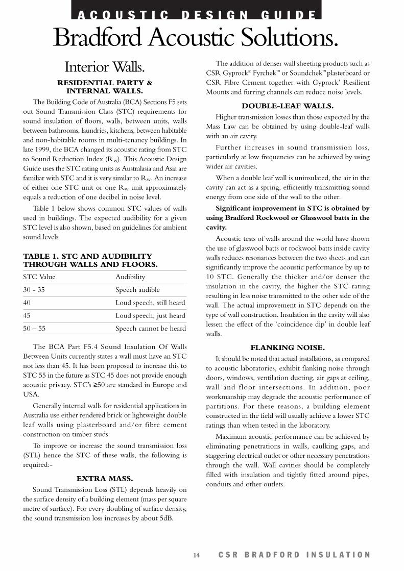
Interior Walls.RESIDENTIAL PARTY &
INTERNAL WALLS.The Building Code of Australia (BCA) Sections F5 sets
out Sound Transmission Class (STC) requirements forsound insulation of floors, walls, between units, wallsbetween bathrooms, laundries, kitchens, between habitableand non-habitable rooms in multi-tenancy buildings. Inlate 1999, the BCA changed its acoustic rating from STCto Sound Reduction Index (Rw). This Acoustic DesignGuide uses the STC rating units as Australasia and Asia arefamiliar with STC and it is very similar to Rw. An increaseof either one STC unit or one Rw unit approximatelyequals a reduction of one decibel in noise level.
Table 1 below shows common STC values of wallsused in buildings. The expected audibility for a givenSTC level is also shown, based on guidelines for ambientsound levels
TABLE 1. STC AND AUDIBILITYTHROUGH WALLS AND FLOORS.
STC Value Audibility
30 - 35 Speech audible
40 Loud speech, still heard
45 Loud speech, just heard
50 – 55 Speech cannot be heard
The BCA Part F5.4 Sound Insulation Of WallsBetween Units currently states a wall must have an STCnot less than 45. It has been proposed to increase this toSTC 55 in the future as STC 45 does not provide enoughacoustic privacy. STC’s ≥50 are standard in Europe andUSA.
Generally internal walls for residential applications inAustralia use either rendered brick or lightweight doubleleaf walls using plasterboard and/or fibre cementconstruction on timber studs.
To improve or increase the sound transmission loss(STL) hence the STC of these walls, the following isrequired:-
EXTRA MASS.Sound Transmission Loss (STL) depends heavily on
the surface density of a building element (mass per squaremetre of surface). For every doubling of surface density,the sound transmission loss increases by about 5dB.
The addition of denser wall sheeting products such asCSR Gyprock® Fyrchek™ or Soundchek™ plasterboard orCSR Fibre Cement together with Gyprock’ ResilientMounts and furring channels can reduce noise levels.
DOUBLE-LEAF WALLS.Higher transmission losses than those expected by the
Mass Law can be obtained by using double-leaf wallswith an air cavity.
Further increases in sound transmission loss,particularly at low frequencies can be achieved by usingwider air cavities.
When a double leaf wall is uninsulated, the air in thecavity can act as a spring, efficiently transmitting soundenergy from one side of the wall to the other.
Significant improvement in STC is obtained byusing Bradford Rockwool or Glasswool batts in thecavity.
Acoustic tests of walls around the world have shownthe use of glasswool batts or rockwool batts inside cavitywalls reduces resonances between the two sheets and cansignificantly improve the acoustic performance by up to10 STC. Generally the thicker and/or denser theinsulation in the cavity, the higher the STC ratingresulting in less noise transmitted to the other side of thewall. The actual improvement in STC depends on thetype of wall construction. Insulation in the cavity will alsolessen the effect of the ‘coincidence dip’ in double leafwalls.
FLANKING NOISE.It should be noted that actual installations, as compared
to acoustic laboratories, exhibit flanking noise throughdoors, windows, ventilation ducting, air gaps at ceiling,wall and floor intersections. In addition, poorworkmanship may degrade the acoustic performance ofpartitions. For these reasons, a building elementconstructed in the field will usually achieve a lower STCratings than when tested in the laboratory.
Maximum acoustic performance can be achieved byeliminating penetrations in walls, caulking gaps, andstaggering electrical outlet or other necessary penetrationsthrough the wall. Wall cavities should be completelyfilled with insulation and tightly fitted around pipes,conduits and other outlets.
Bradford Acoustic Solutions.

A C O U S T I C D E S I G N G U I D E
C S R B R A D F O R D I N S U L A T I O N15
LOW FREQUENCY NOISE.Low frequency noise from sources such as fans, aircraft,
road and rail traffic, and bass from amplified music canpenetrate walls easier than high frequency noise.Therefore higher sound transmission loss (ie. higherSTC) walls are required to ensure satisfactory acousticperformance. As a general rule, add at least 5 STC pointsto the acoustic requirement of the walls when lowfrequency noise is present.
STC data for some typical partition walls is given inTable 2. Further STC data for internal cavity walls isavailable the CSR Bradford brochure ‘Noise ReductionsFor Internal Partitions or the CSR Gyprock Fire &Acoustic Design Guide, ‘The Red Book’.
TABLE 2. STC DATA FOR TYPICAL TIMBER FRAME PARTITION SYSTEMS.
Description STC (Rw) STC (Rw) STC (Rw)Bradford Bradford
No Glasswool RockwoolInsulation Wall Batts Wall Batts
STC 30 - 42
• 1 layer 10mm CSR Gyprock Plasterboard CD™
• 70/75mm Timber Studs
• 1 layer 10mm CSR Gyprock Plasterboard CD™
STC 40 - 50
• 2 layers 13mm CSR Gyprock Fyrchek™ plasterboard
• 70/75mm Timber Studs
• 1 layer 13mm CSR Gyprock Fyrchek™ plasterboard
STC 50 - 60
• 2 layers 16mm CSR Gyprock Fyrchek™ plasterboard
• 90 x 35mm Staggered Timber Studs
• 2 layers 16mm CSR Gyprock Fyrchek™ plasterboard
33 38 39(75mm Batts) (45mm Batts)
Test CSR 37/67
42SoundScreen™
43 47 48
(50mm Batts) (45mm Batts)
51 58 59
(50mm Batts) (45mm Batts)
* Refer to the CSR Bradford Noise Reduction of Internal Partitions brochure or the CSR Gyprock® Fire & AcousticDesign Guide (‘The Red Book’) which show a wide range of internal partitions and their STC ratings.
A C O U S T I C D E S I G N G U I D E
C S R B R A D F O R D I N S U L A T I O N16
Internal plasterboard or fibre cement walls using steelstud systems are widely used in commercial constructionand offer a wide range of sound transmission lossperformance.
The methods stated previously for improving acousticperformance of Residential Internal Walls also apply tothe Commercial Internal Partitions.
Thinner gauge steel studs, with greater stud spacingand minimum fixing of sheets to studs also results in a wallwhich is able to flex more easily generally resulting inslightly higher acoustic performance.
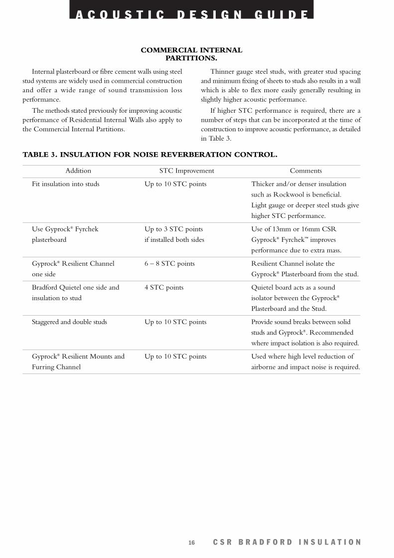
If higher STC performance is required, there are anumber of steps that can be incorporated at the time ofconstruction to improve acoustic performance, as detailedin Table 3.
TABLE 3. INSULATION FOR NOISE REVERBERATION CONTROL.
Addition STC Improvement Comments
Fit insulation into studs Up to 10 STC points Thicker and/or denser insulation
such as Rockwool is beneficial.
Light gauge or deeper steel studs give
higher STC performance.
Use Gyprock® Fyrchek Up to 3 STC points Use of 13mm or 16mm CSR
plasterboard if installed both sides Gyprock® Fyrchek™ improves
performance due to extra mass.
Gyprock® Resilient Channel 6 – 8 STC points Resilient Channel isolate the
one side Gyprock® Plasterboard from the stud.
Bradford Quietel one side and 4 STC points Quietel board acts as a sound
insulation to stud isolator between the Gyprock®
Plasterboard and the Stud.
Staggered and double studs Up to 10 STC points Provide sound breaks between solid
studs and Gyprock®. Recommended
where impact isolation is also required.
Gyprock® Resilient Mounts and Up to 10 STC points Used where high level reduction of
Furring Channel airborne and impact noise is required.
COMMERCIAL INTERNALPARTITIONS.
A C O U S T I C D E S I G N G U I D E
C S R B R A D F O R D I N S U L A T I O N17
* Refer to the CSR Bradford Insulation Noise Reduction of Internal Partitions brochure or CSR Gyprock® Fire &Acoustic Design Guide (‘The Red Book’) which show a wide range of internal partitions and their STC ratings.
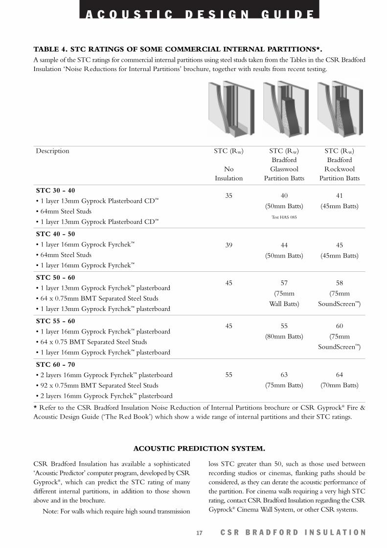
Description STC (Rw) STC (Rw) STC (Rw)Bradford Bradford
No Glasswool RockwoolInsulation Partition Batts Partition Batts
STC 30 - 40
• 1 layer 13mm Gyprock Plasterboard CD™
• 64mm Steel Studs
• 1 layer 13mm Gyprock Plasterboard CD™
STC 40 - 50
• 1 layer 16mm Gyprock Fyrchek™
• 64mm Steel Studs
• 1 layer 16mm Gyprock Fyrchek™
STC 50 - 60
• 1 layer 13mm Gyprock Fyrchek™ plasterboard
• 64 x 0.75mm BMT Separated Steel Studs
• 1 layer 13mm Gyprock Fyrchek™ plasterboard
STC 55 - 60
• 1 layer 16mm Gyprock Fyrchek™ plasterboard
• 64 x 0.75 BMT Separated Steel Studs
• 1 layer 16mm Gyprock Fyrchek™ plasterboard
STC 60 - 70
• 2 layers 16mm Gyprock Fyrchek™ plasterboard
• 92 x 0.75mm BMT Separated Steel Studs
• 2 layers 16mm Gyprock Fyrchek™ plasterboard
TABLE 4. STC RATINGS OF SOME COMMERCIAL INTERNAL PARTITIONS*.A sample of the STC ratings for commercial internal partitions using steel studs taken from the Tables in the CSR BradfordInsulation ‘Noise Reductions for Internal Partitions’ brochure, together with results from recent testing.
35 40 41
(50mm Batts) (45mm Batts)
Test HAS 085
39 44 45
(50mm Batts) (45mm Batts)
45 57 58
(75mm (75mm
Wall Batts) SoundScreen™)
45 55 60
(80mm Batts) (75mm
SoundScreen™)
55 63 64
(75mm Batts) (70mm Batts)
CSR Bradford Insulation has available a sophisticated‘Acoustic Predictor’ computer program, developed by CSRGyprock®, which can predict the STC rating of manydifferent internal partitions, in addition to those shownabove and in the brochure.
Note: For walls which require high sound transmission
loss STC greater than 50, such as those used betweenrecording studios or cinemas, flanking paths should beconsidered, as they can derate the acoustic performance ofthe partition. For cinema walls requiring a very high STCrating, contact CSR Bradford Insulation regarding the CSRGyprock® Cinema Wall System, or other CSR systems.
ACOUSTIC PREDICTION SYSTEM.
A C O U S T I C D E S I G N G U I D E
C S R B R A D F O R D I N S U L A T I O N18
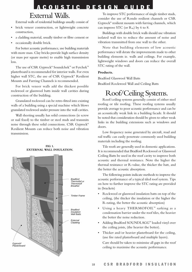
External Walls.External walls of residential buildings usually consist of
• brick veneer construction, or lightweight concreteconstruction,
• a cladding material, usually timber or fibre cement or
• occasionally double brick.
For better acoustic performance, use building materialswith more mass. Clay bricks provide high surface density(or mass per square metre) to enable high transmissionloss.
The use of CSR Gyprock® Soundchek™ or Fyrchek™
plasterboard is recommended for interior walls. For evenhigher wall STC, the use of CSR Gyprock® ResilientMounts and Furring Channels is recommended.
For brick veneer walls add the thickest possiblerockwool or glasswool batts inside wall cavities duringconstruction of the building.
Granulated rockwool can be retro-fitted into existingwalls of a building using a special machine which blowsgranulated rockwool under pressure into the wall cavities.
Wall sheeting usually has solid connections (ie screwor nail fixed) to the timber or steel studs and transmitsnoise through these solid connections. CSR Gyprock®
Resilient Mounts can reduce both noise and vibrationtransmission.
To improve STC performance of single timber studs,consider the use of Rondo resilient channels or CSRGyprock® resilient mounts with furring channels, whichcan improve STC (or Rw) by 6 to 8.
Buildings with double brick walls should use vibrationisolated wall ties to reduce the amount of noise andvibration transmitted from one wall to the other.
Note that building elements of low acousticperformance will derate the improvements made to otherbuilding elements ie. walls and ceilings. For example,lightweight windows and doors can reduce the overallSTC rating of the wall.
Products.
Bradford Glasswool Wall Batts
Bradford Rockwool Wall and Ceiling Batts
Roof/Ceiling Systems.Roof/ceiling systems generally consist of either steel
roofing or tile roofing. These roofing systems usuallyprovide average to poor acoustic performance and can bean acoustically weak link in a building facade. It shouldbe noted that consideration should be given to other weaklinks in the building extensions such as windows anddoors.
Low frequency noise generated by aircraft, road andrail traffic can easily penetrate commonly used buildingmaterials including the roofing.
Tile roofs are generally used in domestic applications.It is recommended that Bradford Rockwool or GlasswoolCeiling Batts be used in the roof cavity to improve bothacoustic and thermal resistance. Note the higher thethermal resistance or R-value, the thicker the batt, andthe better the acoustic absorption.
The following points indicate methods to improve theacoustic performance of a typical tiled roof system. Tipson how to further improve the STC rating are providedin (brackets)
• Rockwool or glasswool insulation batts on top of theceiling, (the thicker the insulation or the higher theR-rating, the better the acoustic absorption)
• Using a heavy THERMOFOIL™ sarking as acondensation barrier under the roof tiles, the heavierthe better the noise reduction.
• Adding Bradford SOUNDLAGG™ loaded vinyl overthe ceiling joists, (the heavier the better).
• Thicker and/or heavier plasterboard for the ceiling,(use fire rated plasterboard and multiple layers).
Care should be taken to minimise all gaps in the roofceiling to maximise the acoustic performance.
Gyprock® Plasterboard
Bradford Thermofoil or Thermotuff Breather
Bradford Insulation Wall Batts
External Cladding
Timber Frame
FIG 1. EXTERNAL WALL INSULATION.
A C O U S T I C D E S I G N G U I D E
C S R B R A D F O R D I N S U L A T I O N19
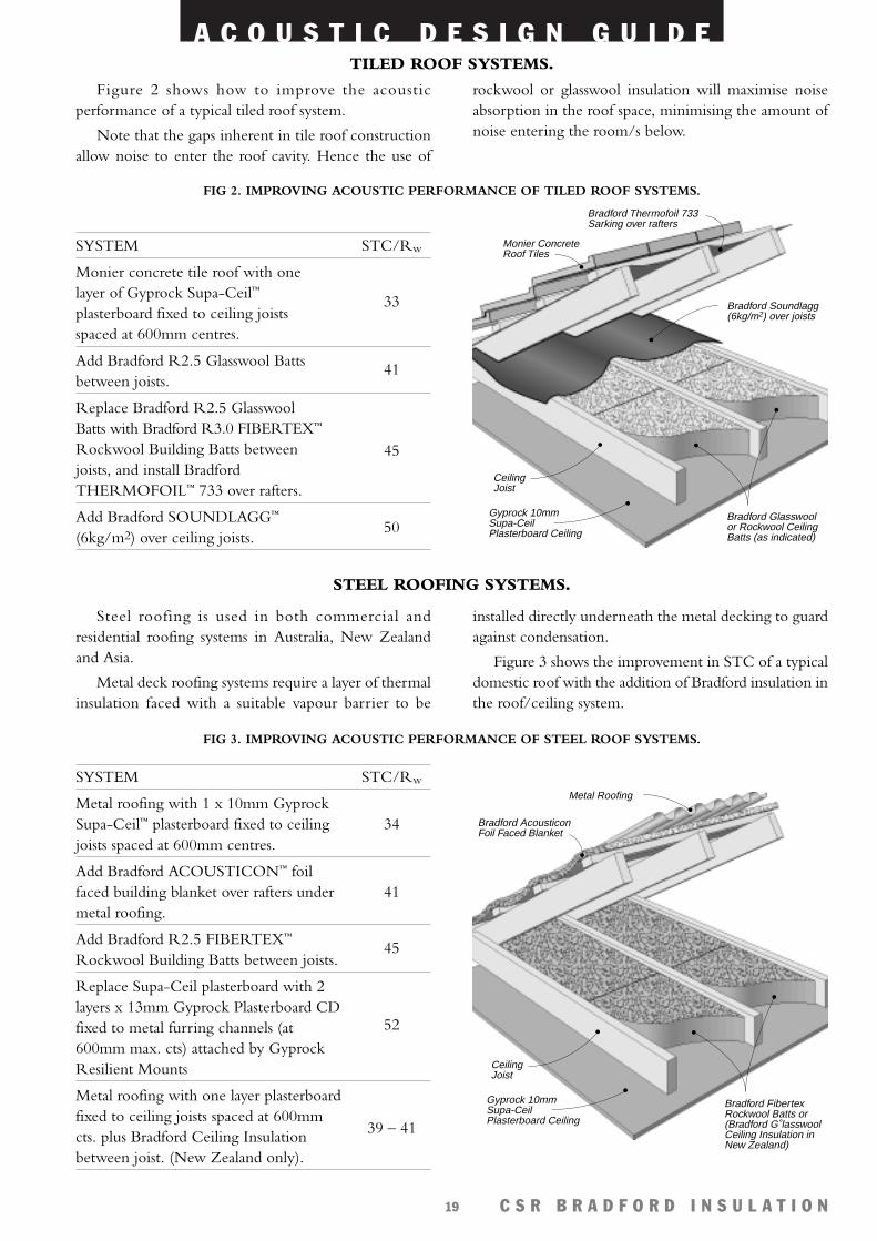
Figure 2 shows how to improve the acousticperformance of a typical tiled roof system.
Note that the gaps inherent in tile roof constructionallow noise to enter the roof cavity. Hence the use of
rockwool or glasswool insulation will maximise noiseabsorption in the roof space, minimising the amount ofnoise entering the room/s below.
Steel roofing is used in both commercial andresidential roofing systems in Australia, New Zealandand Asia.
Metal deck roofing systems require a layer of thermalinsulation faced with a suitable vapour barrier to be
installed directly underneath the metal decking to guardagainst condensation.
Figure 3 shows the improvement in STC of a typicaldomestic roof with the addition of Bradford insulation inthe roof/ceiling system.
Bradford Glasswool or Rockwool Ceiling Batts (as indicated)
Bradford Thermofoil 733 Sarking over rafters
Gyprock 10mm Supa-Ceil Plasterboard Ceiling
Ceiling Joist
Monier Concrete Roof Tiles
Bradford Soundlagg (6kg/m2) over joists
FIG 2. IMPROVING ACOUSTIC PERFORMANCE OF TILED ROOF SYSTEMS.
SYSTEM
Monier concrete tile roof with onelayer of Gyprock Supa-Ceil™
plasterboard fixed to ceiling joistsspaced at 600mm centres.
Add Bradford R2.5 Glasswool Battsbetween joists.
Replace Bradford R2.5 GlasswoolBatts with Bradford R3.0 FIBERTEX™
Rockwool Building Batts betweenjoists, and install BradfordTHERMOFOIL™ 733 over rafters.
Add Bradford SOUNDLAGG™
(6kg/m2) over ceiling joists.
STC/Rw
33
41
45
50
Bradford Fibertex Rockwool Batts or (Bradford G lasswool Ceiling Insulation in New Zealand)
Metal Roofing
Gyprock 10mm Supa-Ceil Plasterboard Ceiling
Ceiling Joist
Bradford Acousticon Foil Faced Blanket
FIG 3. IMPROVING ACOUSTIC PERFORMANCE OF STEEL ROOF SYSTEMS.
SYSTEM
Metal roofing with 1 x 10mm GyprockSupa-Ceil™ plasterboard fixed to ceilingjoists spaced at 600mm centres.
Add Bradford ACOUSTICON™ foilfaced building blanket over rafters undermetal roofing.
Add Bradford R2.5 FIBERTEX™
Rockwool Building Batts between joists.
Replace Supa-Ceil plasterboard with 2layers x 13mm Gyprock Plasterboard CDfixed to metal furring channels (at600mm max. cts) attached by GyprockResilient Mounts
Metal roofing with one layer plasterboardfixed to ceiling joists spaced at 600mmcts. plus Bradford Ceiling Insulationbetween joist. (New Zealand only).
STC/Rw
34
41
45
52
39 – 41
TILED ROOF SYSTEMS.
STEEL ROOFING SYSTEMS.
A C O U S T I C D E S I G N G U I D E
C S R B R A D F O R D I N S U L A T I O N20
The STC of a roof system (commercial, industrial ordomestic) can also be improved with the addition ofheavier building materials such as:
• addition of insulation between the roof sheeting andBradford batts above the ceiling,
• thicker steel roof sheeting,
• using heavier, fire rated plasterboard or multiple layersfor the ceiling,
• installing a layer of Bradford SOUNDLAGG™ beneath (4 kg/m2 or heavier).
RAIN NOISE REDUCTION WITH METAL DECK ROOFING
A common problem of steel roofing is that of rainnoise, particularly in tropical climates with high levels ofrainfall. Rain falling on metal deck roofing can causeunacceptably high noise levels in the space below the roof.The impact causes the stiff lightweight roof sheeting tovibrate, thus emitting noise. Damping the vibration of theroof sheeting reduces the emitted noise.
Rockwool and glasswool blanket products haveexceptional noise absorbing properties providing effectivedamping of the steel roof sheeting.
CSR Bradford Insulation in conjunction with CSRGyprock® have constructed a rain noise testing facility tosimulate rain noise using conventional 0.42mm thickBHP Trimdek Hi-Ten metal roof cladding. The rainnoise test rig has four nozzles spraying water at highpressure simulate high intensity rainfall. Continuous noiselevels of 89dB(A) were created inside the test rig, thisnoise level was used for controlled testing purposes.
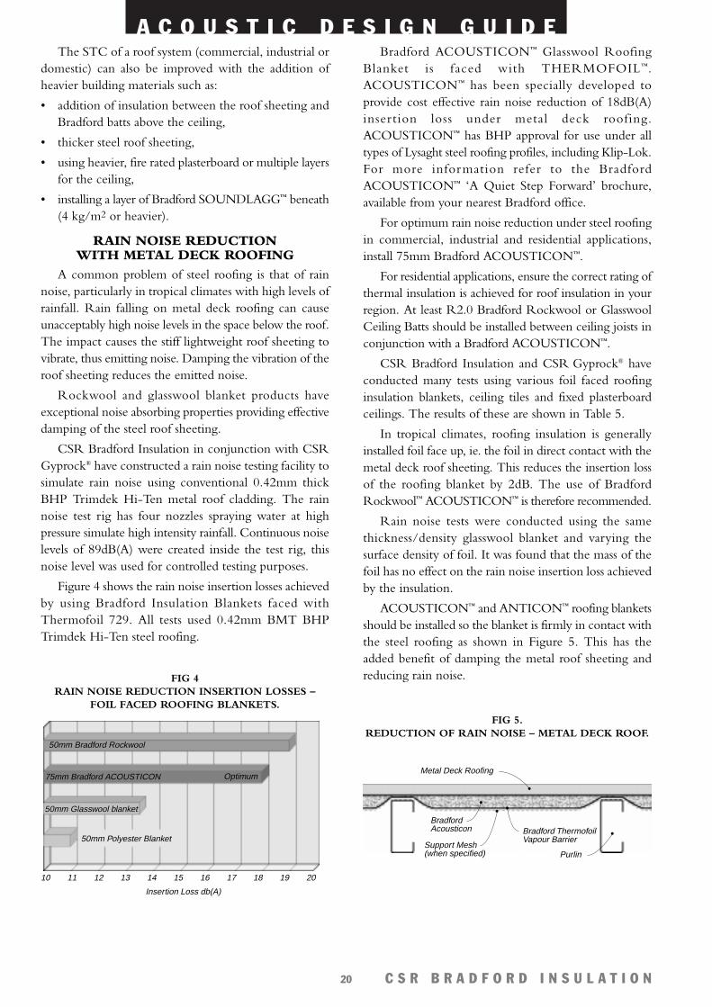
Figure 4 shows the rain noise insertion losses achievedby using Bradford Insulation Blankets faced withThermofoil 729. All tests used 0.42mm BMT BHPTrimdek Hi-Ten steel roofing.
Bradford ACOUSTICON™ Glasswool RoofingBlanket is faced with THERMOFOIL™.ACOUSTICON™ has been specially developed toprovide cost effective rain noise reduction of 18dB(A)insertion loss under metal deck roofing.ACOUSTICON™ has BHP approval for use under alltypes of Lysaght steel roofing profiles, including Klip-Lok.For more information refer to the BradfordACOUSTICON™ ‘A Quiet Step Forward’ brochure,available from your nearest Bradford office.
For optimum rain noise reduction under steel roofingin commercial, industrial and residential applications,install 75mm Bradford ACOUSTICON™.
For residential applications, ensure the correct rating ofthermal insulation is achieved for roof insulation in yourregion. At least R2.0 Bradford Rockwool or GlasswoolCeiling Batts should be installed between ceiling joists inconjunction with a Bradford ACOUSTICON™.
CSR Bradford Insulation and CSR Gyprock® haveconducted many tests using various foil faced roofinginsulation blankets, ceiling tiles and fixed plasterboardceilings. The results of these are shown in Table 5.
In tropical climates, roofing insulation is generallyinstalled foil face up, ie. the foil in direct contact with themetal deck roof sheeting. This reduces the insertion lossof the roofing blanket by 2dB. The use of BradfordRockwool™ ACOUSTICON™ is therefore recommended.
Rain noise tests were conducted using the samethickness/density glasswool blanket and varying thesurface density of foil. It was found that the mass of thefoil has no effect on the rain noise insertion loss achievedby the insulation.
ACOUSTICON™ and ANTICON™ roofing blanketsshould be installed so the blanket is firmly in contact withthe steel roofing as shown in Figure 5. This has theadded benefit of damping the metal roof sheeting andreducing rain noise.
10 11 12 13 14 15 16 17 18 19 20
Insertion Loss db(A)
50mm Glasswool blanket
50mm Bradford Rockwool
75mm Bradford ACOUSTICON Optimum
50mm Polyester Blanket
FIG 4 RAIN NOISE REDUCTION INSERTION LOSSES –
FOIL FACED ROOFING BLANKETS.
Bradford Acousticon
Support Mesh(when specified)
Bradford ThermofoilVapour Barrier
Metal Deck Roofing
Purlin
FIG 5. REDUCTION OF RAIN NOISE – METAL DECK ROOF.
A C O U S T I C D E S I G N G U I D E
C S R B R A D F O R D I N S U L A T I O N21
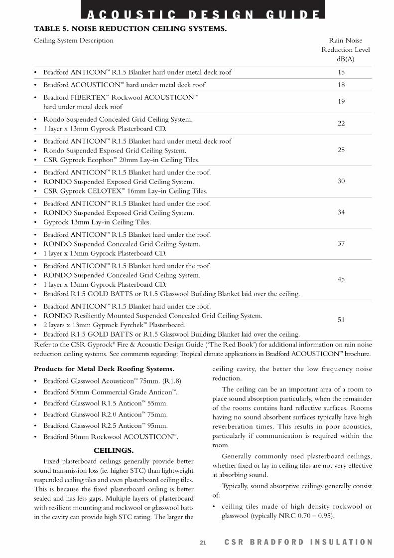
TABLE 5. NOISE REDUCTION CEILING SYSTEMS.
Ceiling System Description Rain NoiseReduction Level
dB(A)
• Bradford ANTICON™ R1.5 Blanket hard under metal deck roof
• Bradford ACOUSTICON™ hard under metal deck roof
• Bradford FIBERTEX™ Rockwool ACOUSTICON™
hard under metal deck roof
• Rondo Suspended Concealed Grid Ceiling System.• 1 layer x 13mm Gyprock Plasterboard CD.
• Bradford ANTICON™ R1.5 Blanket hard under metal deck roof• Rondo Suspended Exposed Grid Ceiling System.• CSR Gyprock Ecophon™ 20mm Lay-in Ceiling Tiles.
• Bradford ANTICON™ R1.5 Blanket hard under the roof. • RONDO Suspended Exposed Grid Ceiling System.• CSR Gyprock CELOTEX™ 16mm Lay-in Ceiling Tiles.
• Bradford ANTICON™ R1.5 Blanket hard under the roof. • RONDO Suspended Exposed Grid Ceiling System.• Gyprock 13mm Lay-in Ceiling Tiles.
• Bradford ANTICON™ R1.5 Blanket hard under the roof. • RONDO Suspended Concealed Grid Ceiling System.• 1 layer x 13mm Gyprock Plasterboard CD.
• Bradford ANTICON™ R1.5 Blanket hard under the roof. • RONDO Suspended Concealed Grid Ceiling System.• 1 layer x 13mm Gyprock Plasterboard CD.• Bradford R1.5 GOLD BATTS or R1.5 Glasswool Building Blanket laid over the ceiling.
• Bradford ANTICON™ R1.5 Blanket hard under the roof. • RONDO Resiliently Mounted Suspended Concealed Grid Ceiling System.• 2 layers x 13mm Gyprock Fyrchek™ Plasterboard.• Bradford R1.5 GOLD BATTS or R1.5 Glasswool Building Blanket laid over the ceiling.
15
18
19
22
25
30
34
37
45
51
Products for Metal Deck Roofing Systems.
• Bradford Glasswool Acousticon™ 75mm. (R1.8)
• Bradford 50mm Commercial Grade Anticon™.
• Bradford Glasswool R1.5 Anticon™ 55mm.
• Bradford Glasswool R2.0 Anticon™ 75mm.
• Bradford Glasswool R2.5 Anticon™ 95mm.
• Bradford 50mm Rockwool ACOUSTICON™.
CEILINGS.Fixed plasterboard ceilings generally provide better
sound transmission loss (ie. higher STC) than lightweightsuspended ceiling tiles and even plasterboard ceiling tiles.This is because the fixed plasterboard ceiling is bettersealed and has less gaps. Multiple layers of plasterboardwith resilient mounting and rockwool or glasswool battsin the cavity can provide high STC rating. The larger the
Refer to the CSR Gyprock® Fire & Acoustic Design Guide (‘The Red Book’) for additional information on rain noisereduction ceiling systems. See comments regarding: Tropical climate applications in Bradford ACOUSTICON™ brochure.
ceiling cavity, the better the low frequency noisereduction.
The ceiling can be an important area of a room toplace sound absorption particularly, when the remainderof the rooms contains hard reflective surfaces. Roomshaving no sound absorbent surfaces typically have highreverberation times. This results in poor acoustics,particularly if communication is required within theroom.
Generally commonly used plasterboard ceilings,whether fixed or lay in ceiling tiles are not very effectiveat absorbing sound.
Typically, sound absorptive ceilings generally consistof:
• ceiling tiles made of high density rockwool orglasswool (typically NRC 0.70 – 0.95),
A C O U S T I C D E S I G N G U I D E
C S R B R A D F O R D I N S U L A T I O N22
• perforated plasterboard or perforated metal pan ceilingswith Bradford Rockwool or Glasswool insulation(faced with a black tissue) above (good soundabsorption NRC 0.60 – 0.90),
• Mineral fibre ceiling tiles (average sound absorptionNRC 0.50 – 0.60).
Note that better low frequency acoustic absorptionresults when ceiling tiles are installed with an air cavity.The larger the air cavity, the better the low frequencyacoustic absorption.
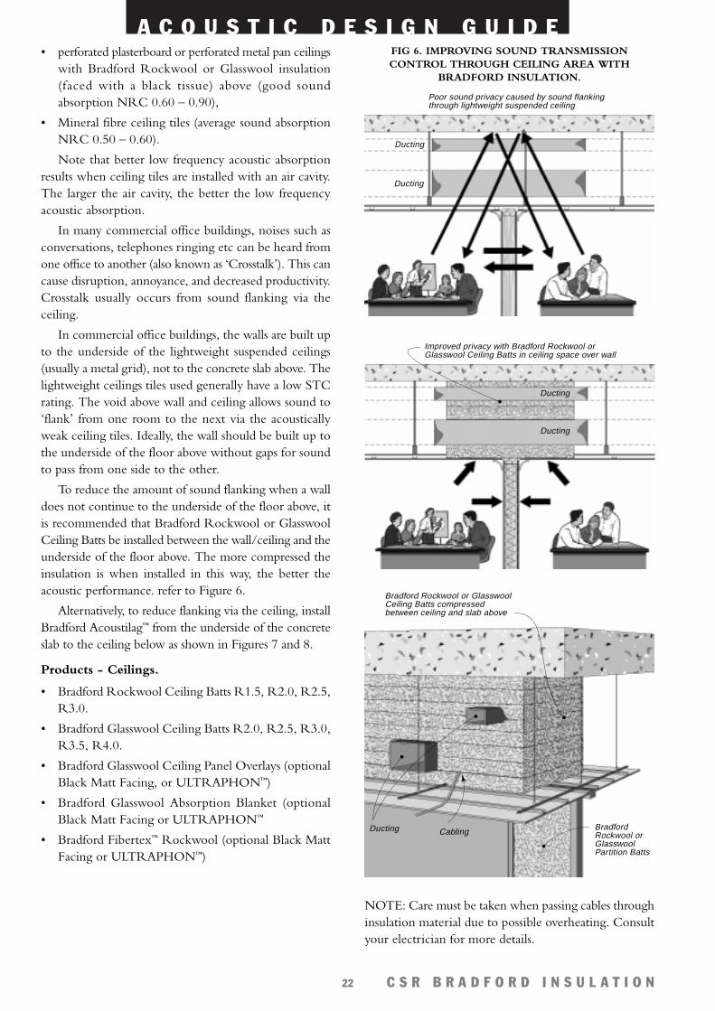
In many commercial office buildings, noises such asconversations, telephones ringing etc can be heard fromone office to another (also known as ‘Crosstalk’). This cancause disruption, annoyance, and decreased productivity.Crosstalk usually occurs from sound flanking via theceiling.
In commercial office buildings, the walls are built upto the underside of the lightweight suspended ceilings(usually a metal grid), not to the concrete slab above. Thelightweight ceilings tiles used generally have a low STCrating. The void above wall and ceiling allows sound to‘flank’ from one room to the next via the acousticallyweak ceiling tiles. Ideally, the wall should be built up tothe underside of the floor above without gaps for soundto pass from one side to the other.
To reduce the amount of sound flanking when a walldoes not continue to the underside of the floor above, itis recommended that Bradford Rockwool or GlasswoolCeiling Batts be installed between the wall/ceiling and theunderside of the floor above. The more compressed theinsulation is when installed in this way, the better theacoustic performance. refer to Figure 6.
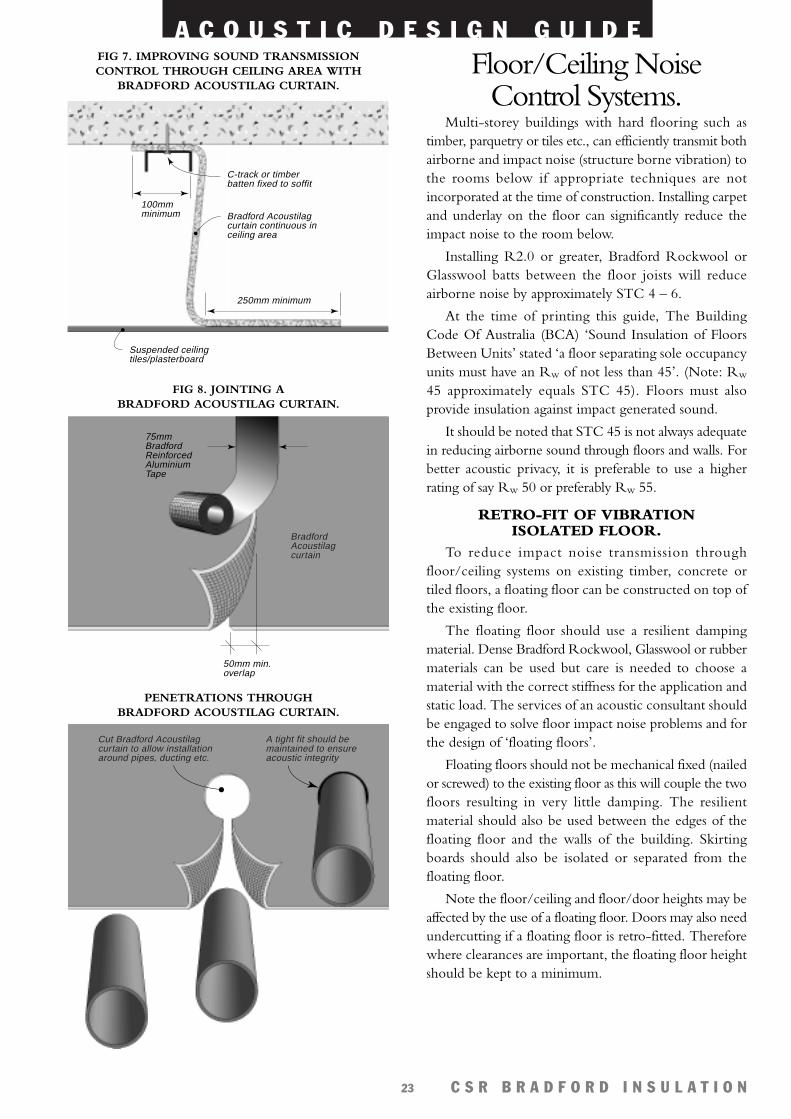
Alternatively, to reduce flanking via the ceiling, installBradford Acoustilag™ from the underside of the concreteslab to the ceiling below as shown in Figures 7 and 8.
Products - Ceilings.
• Bradford Rockwool Ceiling Batts R1.5, R2.0, R2.5,R3.0.
• Bradford Glasswool Ceiling Batts R2.0, R2.5, R3.0,R3.5, R4.0.
• Bradford Glasswool Ceiling Panel Overlays (optionalBlack Matt Facing, or ULTRAPHON™)
• Bradford Glasswool Absorption Blanket (optionalBlack Matt Facing or ULTRAPHON™
• Bradford Fibertex™ Rockwool (optional Black MattFacing or ULTRAPHON™)
Ducting
Ducting
Poor sound privacy caused by sound flanking through lightweight suspended ceiling
FIG 6. IMPROVING SOUND TRANSMISSIONCONTROL THROUGH CEILING AREA WITH
BRADFORD INSULATION.
Ducting
Ducting
Improved privacy with Bradford Rockwool or Glasswool Ceiling Batts in ceiling space over wall
Bradford Rockwool or Glasswool Partition Batts
Bradford Rockwool or Glasswool Ceiling Batts compressed between ceiling and slab above
CablingDucting
NOTE: Care must be taken when passing cables throughinsulation material due to possible overheating. Consultyour electrician for more details.
A C O U S T I C D E S I G N G U I D E
C S R B R A D F O R D I N S U L A T I O N23
Floor/Ceiling NoiseControl Systems.
Multi-storey buildings with hard flooring such astimber, parquetry or tiles etc., can efficiently transmit bothairborne and impact noise (structure borne vibration) tothe rooms below if appropriate techniques are notincorporated at the time of construction. Installing carpetand underlay on the floor can significantly reduce theimpact noise to the room below.
Installing R2.0 or greater, Bradford Rockwool orGlasswool batts between the floor joists will reduceairborne noise by approximately STC 4 – 6.
At the time of printing this guide, The BuildingCode Of Australia (BCA) ‘Sound Insulation of FloorsBetween Units’ stated ‘a floor separating sole occupancyunits must have an Rw of not less than 45’. (Note: Rw
45 approximately equals STC 45). Floors must alsoprovide insulation against impact generated sound.
It should be noted that STC 45 is not always adequatein reducing airborne sound through floors and walls. Forbetter acoustic privacy, it is preferable to use a higherrating of say Rw 50 or preferably Rw 55.
RETRO-FIT OF VIBRATIONISOLATED FLOOR.
To reduce impact noise transmission throughfloor/ceiling systems on existing timber, concrete ortiled floors, a floating floor can be constructed on top ofthe existing floor.
The floating floor should use a resilient dampingmaterial. Dense Bradford Rockwool, Glasswool or rubbermaterials can be used but care is needed to choose amaterial with the correct stiffness for the application andstatic load. The services of an acoustic consultant shouldbe engaged to solve floor impact noise problems and forthe design of ‘floating floors’.
Floating floors should not be mechanical fixed (nailedor screwed) to the existing floor as this will couple the twofloors resulting in very little damping. The resilientmaterial should also be used between the edges of thefloating floor and the walls of the building. Skirtingboards should also be isolated or separated from thefloating floor.
Note the floor/ceiling and floor/door heights may beaffected by the use of a floating floor. Doors may also needundercutting if a floating floor is retro-fitted. Thereforewhere clearances are important, the floating floor heightshould be kept to a minimum.
250mm minimum
100mmminimum
C-track or timber batten fixed to soffit
Bradford Acoustilag curtain continuous in ceiling area
Suspended ceiling tiles/plasterboard
FIG 7. IMPROVING SOUND TRANSMISSIONCONTROL THROUGH CEILING AREA WITH
BRADFORD ACOUSTILAG CURTAIN.
75mm Bradford Reinforced Aluminium Tape
50mm min.overlap
Bradford Acoustilag curtain
FIG 8. JOINTING A BRADFORD ACOUSTILAG CURTAIN.
Cut Bradford Acoustilag curtain to allow installation around pipes, ducting etc.
A tight fit should be maintained to ensure acoustic integrity
PENETRATIONS THROUGH BRADFORD ACOUSTILAG CURTAIN.
A C O U S T I C D E S I G N G U I D E
C S R B R A D F O R D I N S U L A T I O N24
REDUCING NOISE TRANSMISSIONTHROUGH TIMBER
FLOOR/CEILING SYSTEMS.1. Fit Bradford R2.0 (or greater) Floor Batts, or
Rockwool/Glasswool Ceiling Batts tightly betweenceiling joists.
2. Fix one layer of 13mm or 16mm Gyprock Fyrchek™
plasterboard to furring channels.
3. For better acoustic performance (to reduce airbornenoise), choose a ceiling with more mass ie. multiplelayers of Gyprock® plasterboard CD or GyprockFyrchek™ plasterboard.
4. CSR Gyprock® Resilient Mounted Furring Channelswill further improve acoustic performance as well asimpact isolation.
5. To improve impact isolation of floors, use carpet andgood quality thick underlay over timber flooring.
A large range of floor/ceiling systems incorporatingalternative acoustic upgrades is detailed in Appendix B ofthis publication.
Refer to the CSR Gyprock® Fire & Acoustic DesignGuide ‘The Red Book’ for additional information onfloor/ceiling systems.
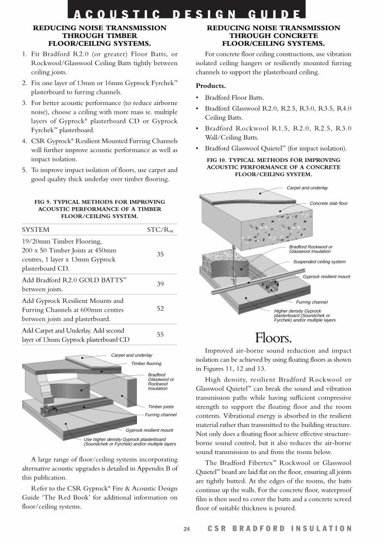
REDUCING NOISE TRANSMISSIONTHROUGH CONCRETE
FLOOR/CEILING SYSTEMS.For concrete floor ceiling constructions, use vibration
isolated ceiling hangers or resiliently mounted furringchannels to support the plasterboard ceiling.
Products.
• Bradford Floor Batts.
• Bradford Glasswool R2.0, R2.5, R3.0, R3.5, R4.0Ceiling Batts.
• Bradford Rockwool R1.5, R2.0, R2.5, R3.0Wall/Ceiling Batts.
• Bradford Glasswool Quietel™ (for impact isolation).
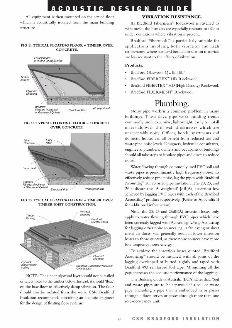
Floors.Improved air-borne sound reduction and impact
isolation can be achieved by using floating floors as shownin Figures 11, 12 and 13.
High density, resilient Bradford Rockwool orGlasswool Quietel™ can break the sound and vibrationtransmission paths while having sufficient compressivestrength to support the floating floor and the roomcontents. Vibrational energy is absorbed in the resilientmaterial rather than transmitted to the building structure.Not only does a floating floor achieve effective structure-borne sound control, but it also reduces the air-bornesound transmission to and from the room below.
The Bradford Fibertex™ Rockwool or GlasswoolQuietel™ board are laid flat on the floor, ensuring all jointsare tightly butted. At the edges of the rooms, the battscontinue up the walls. For the concrete floor, waterprooffilm is then used to cover the batts and a concrete screedfloor of suitable thickness is poured.
Carpet and underlay
Timber flooring
Gyprock resilient mount
Use higher density Gyprock plasterboard (Soundchek or Fyrchek) and/or multiple layers
Furring channel
Bradford Glasswool or Rockwool Insulation
Timber joists
FIG 9. TYPICAL METHODS FOR IMPROVINGACOUSTIC PERFORMANCE OF A TIMBER
FLOOR/CEILING SYSTEM.
Carpet and underlay
Concrete slab floor
Suspended ceiling system
Gyprock resilient mount
Higher density Gyprock plasterboard (Soundchek or Fyrchek) and/or multiple layers
Furring channel
Bradford Rockwool or Glasswool Insulation
FIG 10. TYPICAL METHODS FOR IMPROVINGACOUSTIC PERFORMANCE OF A CONCRETE
FLOOR/CEILING SYSTEM.
SYSTEM
19/20mm Timber Flooring, 200 x 50 Timber Joists at 450mmcentres, 1 layer x 13mm Gyprockplasterboard CD.
Add Bradford R2.0 GOLD BATTS™
between joists.
Add Gyprock Resilient Mounts andFurring Channels at 600mm centresbetween joists and plasterboard.
Add Carpet and Underlay. Add secondlayer of 13mm Gyprock plasterboard CD
STC/Rw
35
39
52
55
A C O U S T I C D E S I G N G U I D E
C S R B R A D F O R D I N S U L A T I O N25
VIBRATION RESISTANCE.As Bradford Fibermesh™ Rockwool is stitched to
wire mesh, the blankets are especially resistant to falloutunder conditions where vibration is present.
Bradford Fibermesh™ is particularly suitable forapplications involving both vibration and hightemperature where standard bonded insulation materialsare less resistant to the effects of vibration.
Products.
• Bradford Glasswool QUIETEL™.
• Bradford FIBERTEX™ HD Rockwool.
• Bradford FIBERTEX™ HD (High Density) Rockwool.
• Bradford FIBERMESH™ Rockwool.
Plumbing.Noisy pipe work is a common problem in many
buildings. These days, pipe work building trendscommonly use inexpensive, lightweight, easily to installmater ials with thin wall thicknesses which areunacceptably noisy. Offices, hotels, apartments anddomestic houses can all benefit from reduced soil andwaste pipe noise levels. Designers, hydraulic consultants,engineers, plumbers, owners and occupants of buildingsshould all take steps to insulate pipes and ducts to reducenoise.
Water flowing through commonly used PVC soil andwaste pipes is predominantly high frequency noise. Toeffectively reduce pipe noise, lag the pipes with BradfordAcoustilag™ 20, 23 or 26 pipe insulation. The 20, 23, and26 indicate the ‘A-weighted’ [dB(A)] insertion lossachieved by lagging PVC pipes with each of the BradfordAcoustilag™ product respectively. (Refer to Appendix Bfor additional information).
Note, the 20, 23 and 26dB(A) insertion losses onlyapply to water flowing through PVC pipes which havebeen correctly lagged with Acoustilag. Using Acoustilagfor lagging other noise sources, eg., a fan casing or sheetmetal air ducts, will generally result in lower insertionlosses to those quoted, as these noise sources have morelow frequency noise energy.
To achieve the insertion losses quoted, BradfordAcoustilag™ should be installed with all joins of thelagging overlapped or butted, tightly and taped withBradford 493 reinforced foil tape. Minimising all thegaps increases the acoustic performance of the lagging.
The Building Code of Australia (BCA) states that: ‘Soiland waste pipes are to be separated if a soil or wastepipe, including a pipe that is embedded in or passesthrough a floor, serves or passes through more than onesole-occupancy unit:
Timber battens
Particleboardor timber board flooring
Structural floorAir gap at wallBradford
Fibertex Rockwoolor Glasswool Quietel
PlywoodSheeting
FIG 11 TYPICAL FLOATING FLOOR – TIMBER OVERCONCRETE.
Floor finish
50mm Concrete
Wire mesh
Structural floor Waterproof film
BradfordFibertex Rockwoolor Glasswool Quietel
FIG 12 TYPICAL FLOATING FLOOR – CONCRETEOVER CONCRETE.
Gyprock plasterboard ceiling
Bradford Quietel Board
Timber flooring
Plywood sheeting
Plywood sheeting
Bradford Glasswool/Rockwool Ceiling Batts
FIG 13 TYPICAL FLOATING FLOOR – TIMBER OVERTIMBER JOIST CONSTRUCTION.
All equipment is then mounted on the screed floorwhich is acoustically isolated from the main buildingstructure.
NOTE: The upper plywood layer should not be nailedor screw fixed to the timber below. Instead, it should ‘float’on the base floor to effectively damp vibration. The floorshould also be isolated from the walls. CSR BradfordInsulation recommends consulting an acoustic engineerfor the design of floating floor systems.
A C O U S T I C D E S I G N G U I D E
C S R B R A D F O R D I N S U L A T I O N26
(a) The pipe must be separated from the rooms of anysole-occupancy unit by construction with an STC notless than:
(i) STC 45 if the adjacent room is a habitable room(other than a kitchen); or
(ii) STC 30 if the adjacent room is a kitchen or anyother room’.
The Bradford ‘ACOUSTILAG™ Pipe Insulation’brochure provides systems using CSR Gyprock®
plasterboard to achieve the STC noise criteria specified bythe BCA. The STC 50 system specified in that brochureis intended for applications requiring better acousticisolation from waste pipe noise than is specified in the BCAeg., board rooms, offices, apartments and hotels etc.
To achieve the STC’s specified in Table 6, it isimperative that the pipes be correctly lagged (no gaps toallow noise leakage), and the plasterboard ceiling and wallsabove be airtight with no gaps into the next room.
It is recommended the services of an acousticconsultant or acoustic engineer be used to achievespecified STC ratings. Penetrations, ducting, light fittings,gaps in ceilings etc., can degrade the acoustic rating of thelagging and ceiling system.
To minimise annoyance from plumbing noise, it isadvisable, at the design stage, to avoid placing bathroomsand laundries etc., adjacent to noise sensitive areas.
Methods for minimising plumbing noise include:
• Select vibration isolated pipe hangers to support pipesand minimise transmission of vibration into thebuilding structure. These will reduce ‘water hammer’noise when turning the water taps on or off.Alternatively use ARMAFLEX® insulation betweenpipes and the building structure.
• Use water supply and drain pipes that are oversized, thismay reduce line pressure and minimise flow noise.
• Where possible, use cast iron waste water pipes in place
of lightweight plastic pipe to substantially reduceplumbing noise. The heavier, stiffer walls of cast ironpipes effectively reduce noise.
• If plastic waste water pipes must be used, use BradfordACOUSTILAG™ to effectively reduce noise.
• Insulate all pipes and plumbing that are chased intobrick walls.
• Select quieter plumbing equipment and appliances eg.cisterns, washing machines, clothes dryers etc.
Products.
• Bradford ACOUSTILAG™ 20, 23 or 26.
• Bradford 493 reinforced foil tape.
• ARMAFLEX® insulation.
Quietening Box Gutters& Downpipes.
Box gutters should be insulated with BradfordFLEXITEL™ or SUPERTEL™ Glasswool (25mm thick)faced with heavy duty foil. Insulation can be attached togutters using 45mm long Bradford self-adhesive fastenersand washers at 300 mm centres. Insulation should be heldfirmly against the metal surface for maximum dampening.For better noise reduction, use Bradford ACOUSTILAG™ 20.
Noisy downpipes should be insulated with BradfordGlasswool Sectional Pipe Insulation faced with HeavyDuty Thermofoil. Alternatively a 25mm wall thicknessARMAFLEX® pipe insulation or BradfordACOUSTILAG™ 20 can be fitted around downpipes.
Products.
• Bradford Glasswool FLEXITEL™ or SUPERTEL™.
• Bradford ACOUSTILAG™ 20.
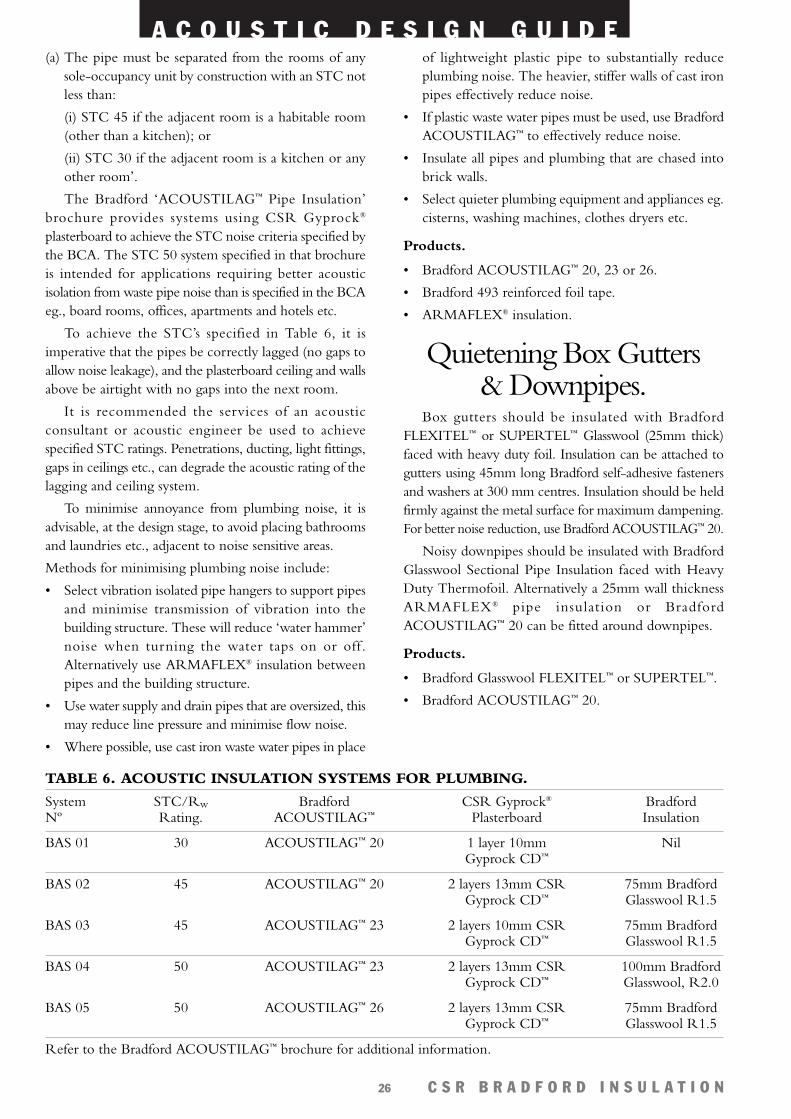
TABLE 6. ACOUSTIC INSULATION SYSTEMS FOR PLUMBING.
System STC/Rw Bradford CSR Gyprock® BradfordNº Rating. ACOUSTILAG™ Plasterboard Insulation
BAS 01 30 ACOUSTILAG™ 20 1 layer 10mm NilGyprock CD™
BAS 02 45 ACOUSTILAG™ 20 2 layers 13mm CSR 75mm BradfordGyprock CD™ Glasswool R1.5
BAS 03 45 ACOUSTILAG™ 23 2 layers 10mm CSR 75mm BradfordGyprock CD™ Glasswool R1.5
BAS 04 50 ACOUSTILAG™ 23 2 layers 13mm CSR 100mm BradfordGyprock CD™ Glasswool, R2.0
BAS 05 50 ACOUSTILAG™ 26 2 layers 13mm CSR 75mm BradfordGyprock CD™ Glasswool R1.5
Refer to the Bradford ACOUSTILAG™ brochure for additional information.
A C O U S T I C D E S I G N G U I D E
C S R B R A D F O R D I N S U L A T I O N27
Insulation Cladding ofPipes, Tanks & Vessels.
The insertion loss achieved by cladding pipes, tanksand vessels will depend on a number of factors such as thefrequency of the fluid in the pipe the type and mass ofthe cladding material, the thickness and density of the(rockwool or glasswool) insulation.
It should be noted that some of these cladding systemscan actually amplify the noise at lower frequencies,particularly if insulation with a high density is used. Thisgenerally happens as the tank now has a larger radiatingsurface. Therefore it is difficult to predict the insertion lossof cladding systems.
It should be noted that Bradford Rockwool orGlasswool SPI (sectional pipe insulation) will reduce pipenoise but not as effectively as Bradford ACOUSTILAG™
or insulation with a mass barrier. Higher density, meansit is less resilient than Bradford ACOUSTILAG™ andmore efficiently transfers noise and vibration from the pipeto the cladding/barrier. Note: Bradford ACOUSTILAG™
is not recommended for high temperature applications.
Refer to the CSR Bradford Industrial InsulationDesign Guide for installation details of cladding and pipelagging.
Factories & EngineeringWorkshops.
The basic methods by which industrial noise may becontrolled are:
• Sound absorption – absorbing the noise using mineralfibre materials which can dissipate the sound energyas heat.
• Sound insulation (enclosing) – containing the noise inone area so that it does not cause annoyance in otherareas.
• Vibration damping – damping vibrating surfaces toreduce air borne sound emission.
• Vibration isolation – preventing acoustic energy fromentering the building structure.
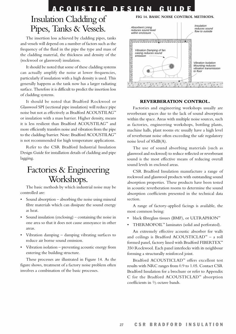
These processes are illustrated in Figure 14. As thefigure shows, treatment of a factory noise problem ofteninvolves a combination of the basic processes.
REVERBERATION CONTROL.Factories and engineering workshops usually are
reverberant spaces due to the lack of sound absorptionwithin the space. Areas with multiple noise sources, suchas factories, engineering workshops, bottling plants,machine halls, plant rooms etc usually have a high levelof reverberant noise often exceeding the safe regulatorynoise level of 85dB(A).
The use of sound absorbing materials (such asglasswool and rockwool) to reduce reflected or reverberantsound is the most effective means of reducing overallsound levels in enclosed areas.
CSR Bradford Insulation manufacture a range ofrockwool and glasswool products with outstanding soundabsorption properties. These products have been testedin acoustic reverberation rooms to determine the soundabsorption coefficients presented in the technical datasection.
A range of factory-applied facings is available, themost common being:
• black fibreglass tissues (BMF), or ULTRAPHON™
• THERMOFOIL™ laminates (solid and perforated).
An extremely effective acoustic absorber for wallsand ceilings is Bradford ACOUSTICLAD™ – a rollformed panel, factory lined with Bradford FIBERTEX™
350 Rockwool. Each panel interlocks with its neighbourforming a structurally reinforced joint.
Bradford ACOUSTICLAD™ offers excellent testresults with NRC ranges from 0.9 to 1.05. Contact CSRBradford Insulation for a brochure or refer to AppendixC for the Bradford ACOUSTICLAD™ absorptioncoefficients in 1/3 octave bands.
Vibration Damping of fancasing reduces soundemission
Insulationreduces soundflow to outside
Absorbent Liningreduces sound levelwithin enclosure
Vibration IsolationMounting reducesvibration transmission to floor
FIG 14. BASIC NOISE CONTROL METHODS.

A C O U S T I C D E S I G N G U I D E
C S R B R A D F O R D I N S U L A T I O N28
Bradford ACOUSTICLAD™ perforated metal isavailable with percentages of open area ranging from10% to 55% and in a number of finishes including:
• galvanised steel,
• powder coated steel,
• stainless steel and
• aluminium.
Fixing details for Bradford ACOUSTICLAD™ areavailable from your nearest Bradford office.
Bradford Rockwool and Glasswool insulation isavailable with a range of facings, including:
• perforated metal or expanded metal.
• perforated foils,
• pegboard,
• wire,
• plastic mesh.
Any perforated sheet facing should have an open areagreater than 10% to maximise acoustic absorption.
Other common methods for acoustic wall treatmentinvolve:
• fixing timber battens or steel furring channels or ‘Z’sections at a spacing to suit the facing sheets. BradfordRockwool and Glasswool batts are cut to size ifnecessary and friction fitted between the supports. Theprotective facing (e.g. perforated or expanded metal,plastic mesh, pegboard, wire etc.) is fixed to thefurring sections or battens by nails, screws, or rivetsas appropriate. Cover strips are used to improve theappearance.
A commonly used cost effective method for fixinginsulation (generally faced with perforated foil) on wallsand ceilings uses drive pins and speed clips. Theseeliminate the need for battens or furring channels. Thedrive pins are fixed to the wall usually at 450mm centres.The insulation is pushed through the pins and held ontothe pin by the speed clips of a suitable size.
Rigid facings such as perforated metal or pegboard areunsuitable for this application method. The advice ofadhesive suppliers should be sought before usingadhesively fixed pins in lieu of drive pins.
Ceilings may be lined by the same methods as walls.An alternative approach is to use a fully exposed metalsuspension grid which makes it a simple matter to achieveany air gap required behind the batts
Factories contain noise which predominantly has mostenergy at low frequencies which is difficult to absorbunless very thick insulation is used. To increase the lowfrequency sound absorption of perforated noise absorbers(such as Bradford ACOUSTICLAD™), introduce an air gapbehind the insulation. This can be achieved by using largerbattens or furring channels with chicken wire to retain thebatts in position, as shown in Figure 15 below. Betteracoustic absorption results when the depth of the air cavityis at least as thick as the insulation.
Alternatively, rockwool or glasswool insulation greaterthan 75mm can be used with acoustically transparentfacings mentioned above.
Acousticlad™ Test Sample Configuration Noise ReductionPerforated Coefficient% Open Area NRC Rating
15% 50mm thick Bradford FIBERTEX™ 350 Rockwool(60kg/m3) Insulation with black matt facing (BMF) 1.00between the Rockwool and Acousticlad face.
25% as above 0.95
40% as above 1.00
15% 23mm thick Mylar film between unfaced Bradford FIBERTEX™ 350 Rockwool and ACOUSTICLAD™ 0.90perforated aluminium.
15% 50mm thick Bradford FIBERTEX™ 350 RockwoolInsulation with black matt tissue between the
1.05Rockwool and perforated aluminium. Timber spacerssupporting panels with average air gap 30mm.
TABLE 7. ACOUSTICLAD™ TEST RESULTS.
Notes – All acoustic tests were conducted with ACOUSTICLAD™ perforated aluminium panels (0.7mm thick), with Bradford 50mm thickFIBERTEX™ 350 Rockwool (60kg/m3) insulation.
– Acoustic tests were conducted in the reverberation room at the National Acoustic Laboratories, Chatswood, Sydney, Australia.– See Appendix C for absorption coefficients at each 1/3 Octave band frequency.
A C O U S T I C D E S I G N G U I D E
C S R B R A D F O R D I N S U L A T I O N29
Products.
• ACOUSTICLAD™ with perforated metal facing isavailable in var ious thicknesses and open areapercentage to accommodate acoustic absorptionrequirements.
The following Bradford products can also be used:
• Bradford Rockwool FIBERTEX™ 350, 450.
• Bradford Glasswool FLEXITEL™, SUPERTEL™,ULTRATEL™ with perforated metal, expanded metal,wire, meshes or perforated heavy duty grade foil facings.
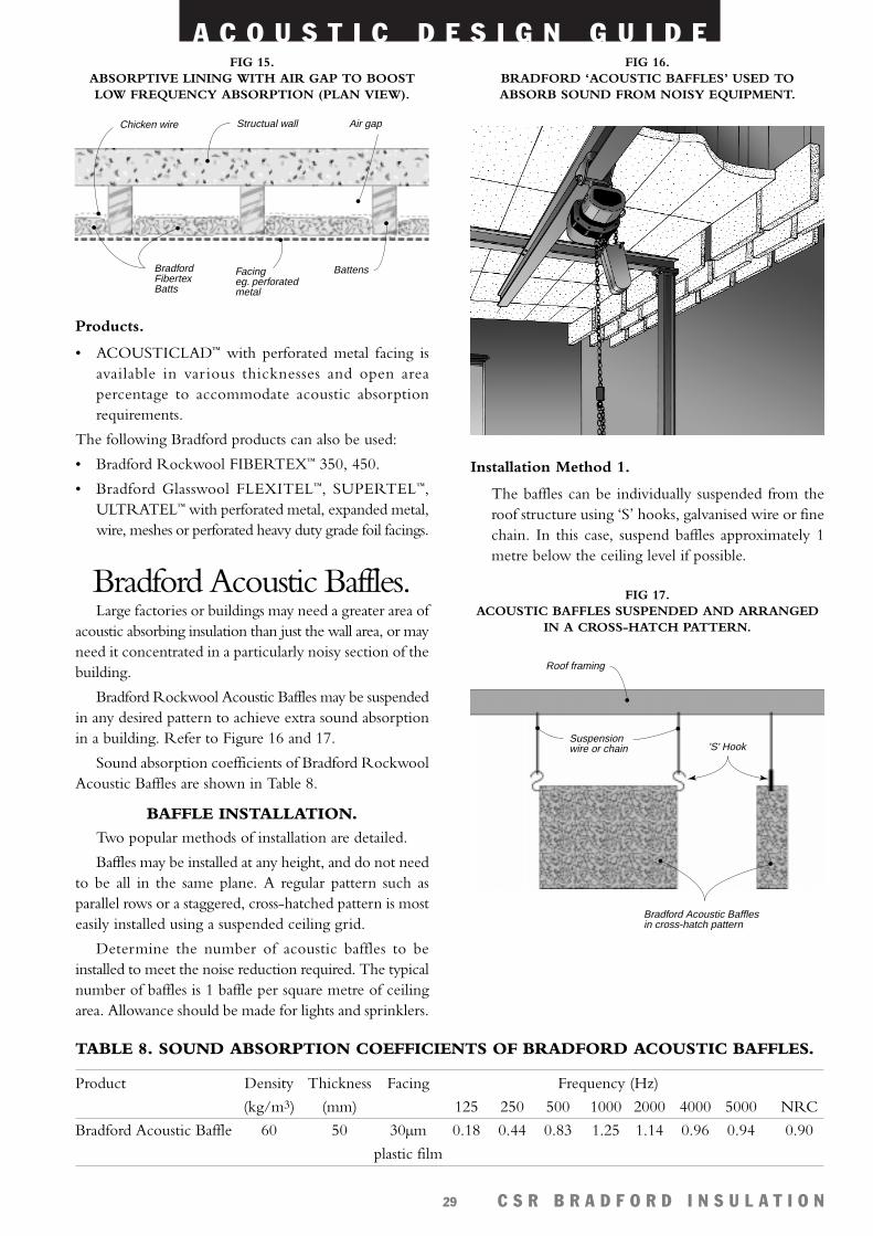
Bradford Acoustic Baffles.Large factories or buildings may need a greater area of
acoustic absorbing insulation than just the wall area, or mayneed it concentrated in a particularly noisy section of thebuilding.
Bradford Rockwool Acoustic Baffles may be suspendedin any desired pattern to achieve extra sound absorptionin a building. Refer to Figure 16 and 17.
Sound absorption coefficients of Bradford RockwoolAcoustic Baffles are shown in Table 8.
BAFFLE INSTALLATION.Two popular methods of installation are detailed.
Baffles may be installed at any height, and do not needto be all in the same plane. A regular pattern such asparallel rows or a staggered, cross-hatched pattern is mosteasily installed using a suspended ceiling grid.
Determine the number of acoustic baffles to beinstalled to meet the noise reduction required. The typicalnumber of baffles is 1 baffle per square metre of ceilingarea. Allowance should be made for lights and sprinklers.
Installation Method 1.
The baffles can be individually suspended from theroof structure using ‘S’ hooks, galvanised wire or finechain. In this case, suspend baffles approximately 1metre below the ceiling level if possible.
Chicken wire Structual wall Air gap
Bradford Fibertex Batts
Facingeg. perforatedmetal
Battens
FIG 15. ABSORPTIVE LINING WITH AIR GAP TO BOOSTLOW FREQUENCY ABSORPTION (PLAN VIEW).
FIG 16. BRADFORD ‘ACOUSTIC BAFFLES’ USED TOABSORB SOUND FROM NOISY EQUIPMENT.
'S' Hook
Roof framing
Bradford Acoustic Bafflesin cross-hatch pattern
Suspension wire or chain
FIG 17. ACOUSTIC BAFFLES SUSPENDED AND ARRANGED
IN A CROSS-HATCH PATTERN.
TABLE 8. SOUND ABSORPTION COEFFICIENTS OF BRADFORD ACOUSTIC BAFFLES.
Product Density Thickness Facing Frequency (Hz)
(kg/m3) (mm) 125 250 500 1000 2000 4000 5000 NRC
Bradford Acoustic Baffle 60 50 30µm 0.18 0.44 0.83 1.25 1.14 0.96 0.94 0.90
plastic film
A C O U S T I C D E S I G N G U I D E
C S R B R A D F O R D I N S U L A T I O N30
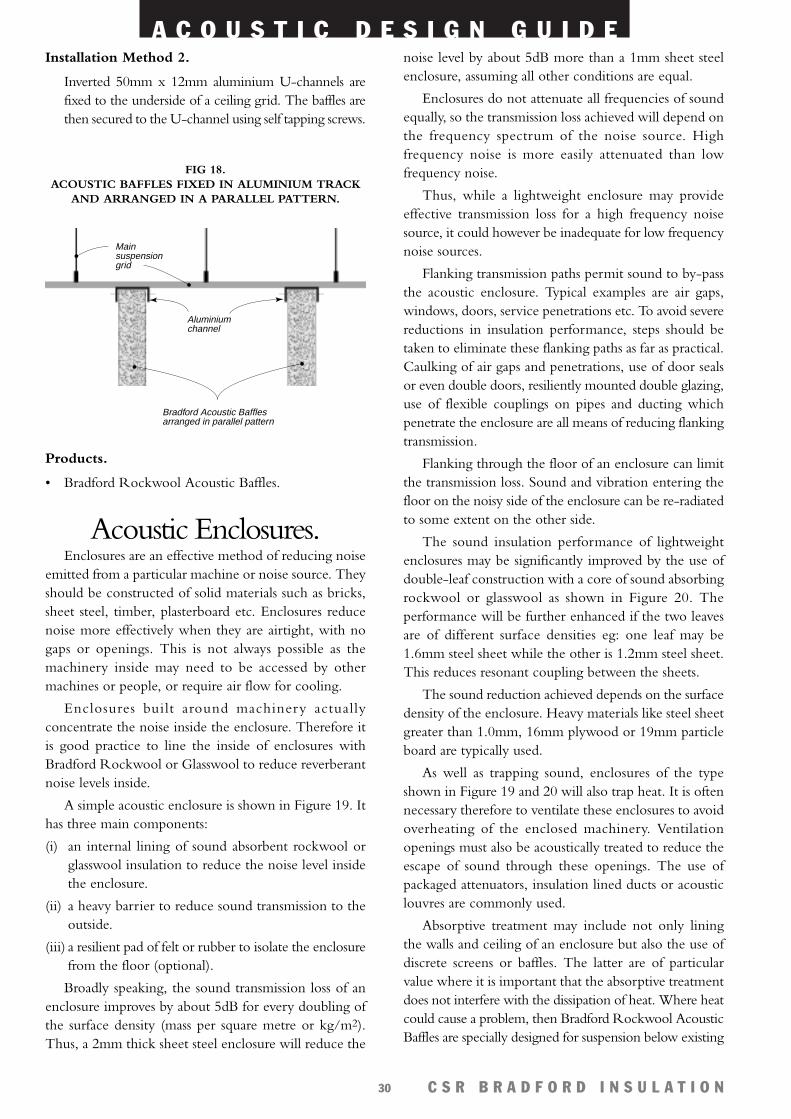
Installation Method 2.
Inverted 50mm x 12mm aluminium U-channels arefixed to the underside of a ceiling grid. The baffles arethen secured to the U-channel using self tapping screws.
Products.
• Bradford Rockwool Acoustic Baffles.
Acoustic Enclosures.Enclosures are an effective method of reducing noise
emitted from a particular machine or noise source. Theyshould be constructed of solid materials such as bricks,sheet steel, timber, plasterboard etc. Enclosures reducenoise more effectively when they are airtight, with nogaps or openings. This is not always possible as themachinery inside may need to be accessed by othermachines or people, or require air flow for cooling.
Enclosures built around machinery actuallyconcentrate the noise inside the enclosure. Therefore itis good practice to line the inside of enclosures withBradford Rockwool or Glasswool to reduce reverberantnoise levels inside.
A simple acoustic enclosure is shown in Figure 19. Ithas three main components:
(i) an internal lining of sound absorbent rockwool orglasswool insulation to reduce the noise level insidethe enclosure.
(ii) a heavy barrier to reduce sound transmission to theoutside.
(iii) a resilient pad of felt or rubber to isolate the enclosurefrom the floor (optional).
Broadly speaking, the sound transmission loss of anenclosure improves by about 5dB for every doubling ofthe surface density (mass per square metre or kg/m2).Thus, a 2mm thick sheet steel enclosure will reduce the
noise level by about 5dB more than a 1mm sheet steelenclosure, assuming all other conditions are equal.
Enclosures do not attenuate all frequencies of soundequally, so the transmission loss achieved will depend onthe frequency spectrum of the noise source. Highfrequency noise is more easily attenuated than lowfrequency noise.
Thus, while a lightweight enclosure may provideeffective transmission loss for a high frequency noisesource, it could however be inadequate for low frequencynoise sources.
Flanking transmission paths permit sound to by-passthe acoustic enclosure. Typical examples are air gaps,windows, doors, service penetrations etc. To avoid severereductions in insulation performance, steps should betaken to eliminate these flanking paths as far as practical.Caulking of air gaps and penetrations, use of door sealsor even double doors, resiliently mounted double glazing,use of flexible couplings on pipes and ducting whichpenetrate the enclosure are all means of reducing flankingtransmission.
Flanking through the floor of an enclosure can limitthe transmission loss. Sound and vibration entering thefloor on the noisy side of the enclosure can be re-radiatedto some extent on the other side.
The sound insulation performance of lightweightenclosures may be significantly improved by the use ofdouble-leaf construction with a core of sound absorbingrockwool or glasswool as shown in Figure 20. Theperformance will be further enhanced if the two leavesare of different surface densities eg: one leaf may be1.6mm steel sheet while the other is 1.2mm steel sheet.This reduces resonant coupling between the sheets.
The sound reduction achieved depends on the surfacedensity of the enclosure. Heavy materials like steel sheetgreater than 1.0mm, 16mm plywood or 19mm particleboard are typically used.
As well as trapping sound, enclosures of the typeshown in Figure 19 and 20 will also trap heat. It is oftennecessary therefore to ventilate these enclosures to avoidoverheating of the enclosed machinery. Ventilationopenings must also be acoustically treated to reduce theescape of sound through these openings. The use ofpackaged attenuators, insulation lined ducts or acousticlouvres are commonly used.
Absorptive treatment may include not only liningthe walls and ceiling of an enclosure but also the use ofdiscrete screens or baffles. The latter are of particularvalue where it is important that the absorptive treatmentdoes not interfere with the dissipation of heat. Where heatcould cause a problem, then Bradford Rockwool AcousticBaffles are specially designed for suspension below existing
Bradford Acoustic Bafflesarranged in parallel pattern
Aluminium channel
Main suspension grid
FIG 18. ACOUSTIC BAFFLES FIXED IN ALUMINIUM TRACK
AND ARRANGED IN A PARALLEL PATTERN.
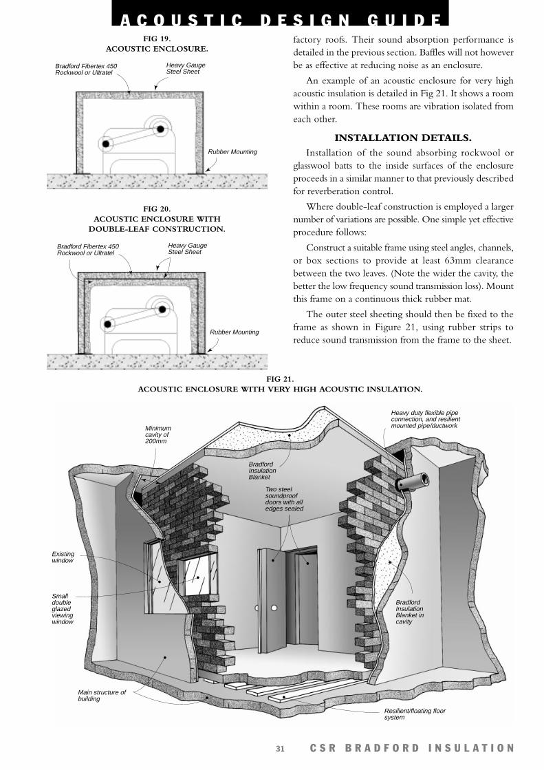
Heavy duty flexible pipe connection, and resilient mounted pipe/ductwork
Main structure of building
Bradford Insulation Blanket
Minimum cavity of 200mm
Existing window
Small double glazed viewing window
Two steel soundproof doors with all edges sealed
Resilient/floating floor system
Bradford Insulation Blanket in cavity
A C O U S T I C D E S I G N G U I D E
C S R B R A D F O R D I N S U L A T I O N31
factory roofs. Their sound absorption performance isdetailed in the previous section. Baffles will not howeverbe as effective at reducing noise as an enclosure.
An example of an acoustic enclosure for very highacoustic insulation is detailed in Fig 21. It shows a roomwithin a room. These rooms are vibration isolated fromeach other.
INSTALLATION DETAILS.Installation of the sound absorbing rockwool or
glasswool batts to the inside surfaces of the enclosureproceeds in a similar manner to that previously describedfor reverberation control.
Where double-leaf construction is employed a largernumber of variations are possible. One simple yet effectiveprocedure follows:
Construct a suitable frame using steel angles, channels,or box sections to provide at least 63mm clearancebetween the two leaves. (Note the wider the cavity, thebetter the low frequency sound transmission loss). Mountthis frame on a continuous thick rubber mat.
The outer steel sheeting should then be fixed to theframe as shown in Figure 21, using rubber strips toreduce sound transmission from the frame to the sheet.
Bradford Fibertex 450 Rockwool or Ultratel
Heavy GaugeSteel Sheet
Rubber Mounting
FIG 19. ACOUSTIC ENCLOSURE.
Bradford Fibertex 450 Rockwool or Ultratel
Heavy GaugeSteel Sheet
Rubber Mounting
FIG 20. ACOUSTIC ENCLOSURE WITH
DOUBLE-LEAF CONSTRUCTION.
FIG 21. ACOUSTIC ENCLOSURE WITH VERY HIGH ACOUSTIC INSULATION.
A C O U S T I C D E S I G N G U I D E
C S R B R A D F O R D I N S U L A T I O N32
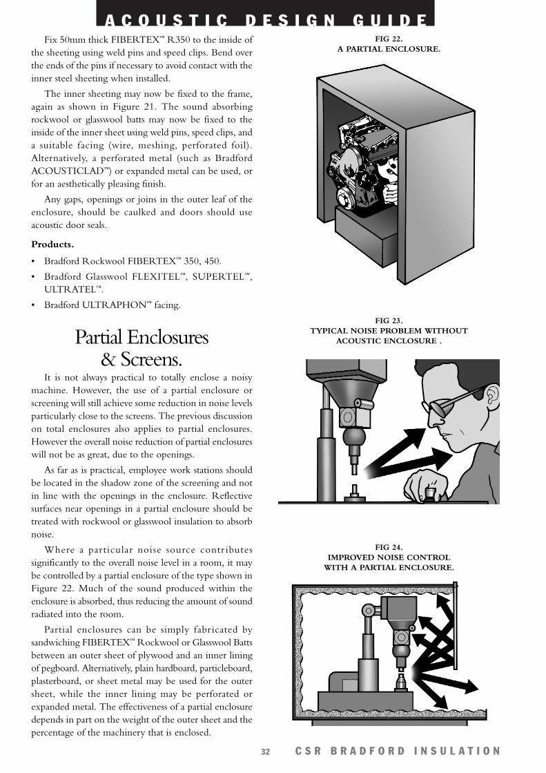
Fix 50mm thick FIBERTEX™ R350 to the inside ofthe sheeting using weld pins and speed clips. Bend overthe ends of the pins if necessary to avoid contact with theinner steel sheeting when installed.
The inner sheeting may now be fixed to the frame,again as shown in Figure 21. The sound absorbingrockwool or glasswool batts may now be fixed to theinside of the inner sheet using weld pins, speed clips, anda suitable facing (wire, meshing, perforated foil).Alternatively, a perforated metal (such as BradfordACOUSTICLAD™) or expanded metal can be used, orfor an aesthetically pleasing finish.
Any gaps, openings or joins in the outer leaf of theenclosure, should be caulked and doors should useacoustic door seals.
Products.
• Bradford Rockwool FIBERTEX™ 350, 450.
• Bradford Glasswool FLEXITEL™, SUPERTEL™,ULTRATEL™.
• Bradford ULTRAPHON™ facing.
Partial Enclosures& Screens.
It is not always practical to totally enclose a noisymachine. However, the use of a partial enclosure orscreening will still achieve some reduction in noise levelsparticularly close to the screens. The previous discussionon total enclosures also applies to partial enclosures.However the overall noise reduction of partial enclosureswill not be as great, due to the openings.
As far as is practical, employee work stations shouldbe located in the shadow zone of the screening and notin line with the openings in the enclosure. Reflectivesurfaces near openings in a partial enclosure should betreated with rockwool or glasswool insulation to absorbnoise.
Where a particular noise source contr ibutessignificantly to the overall noise level in a room, it maybe controlled by a partial enclosure of the type shown inFigure 22. Much of the sound produced within theenclosure is absorbed, thus reducing the amount of soundradiated into the room.
Partial enclosures can be simply fabricated bysandwiching FIBERTEX™ Rockwool or Glasswool Battsbetween an outer sheet of plywood and an inner liningof pegboard. Alternatively, plain hardboard, particleboard,plasterboard, or sheet metal may be used for the outersheet, while the inner lining may be perforated orexpanded metal. The effectiveness of a partial enclosuredepends in part on the weight of the outer sheet and thepercentage of the machinery that is enclosed.
FIG 22. A PARTIAL ENCLOSURE.
FIG 23. TYPICAL NOISE PROBLEM WITHOUT
ACOUSTIC ENCLOSURE .
FIG 24. IMPROVED NOISE CONTROL
WITH A PARTIAL ENCLOSURE.
A C O U S T I C D E S I G N G U I D E
C S R B R A D F O R D I N S U L A T I O N33
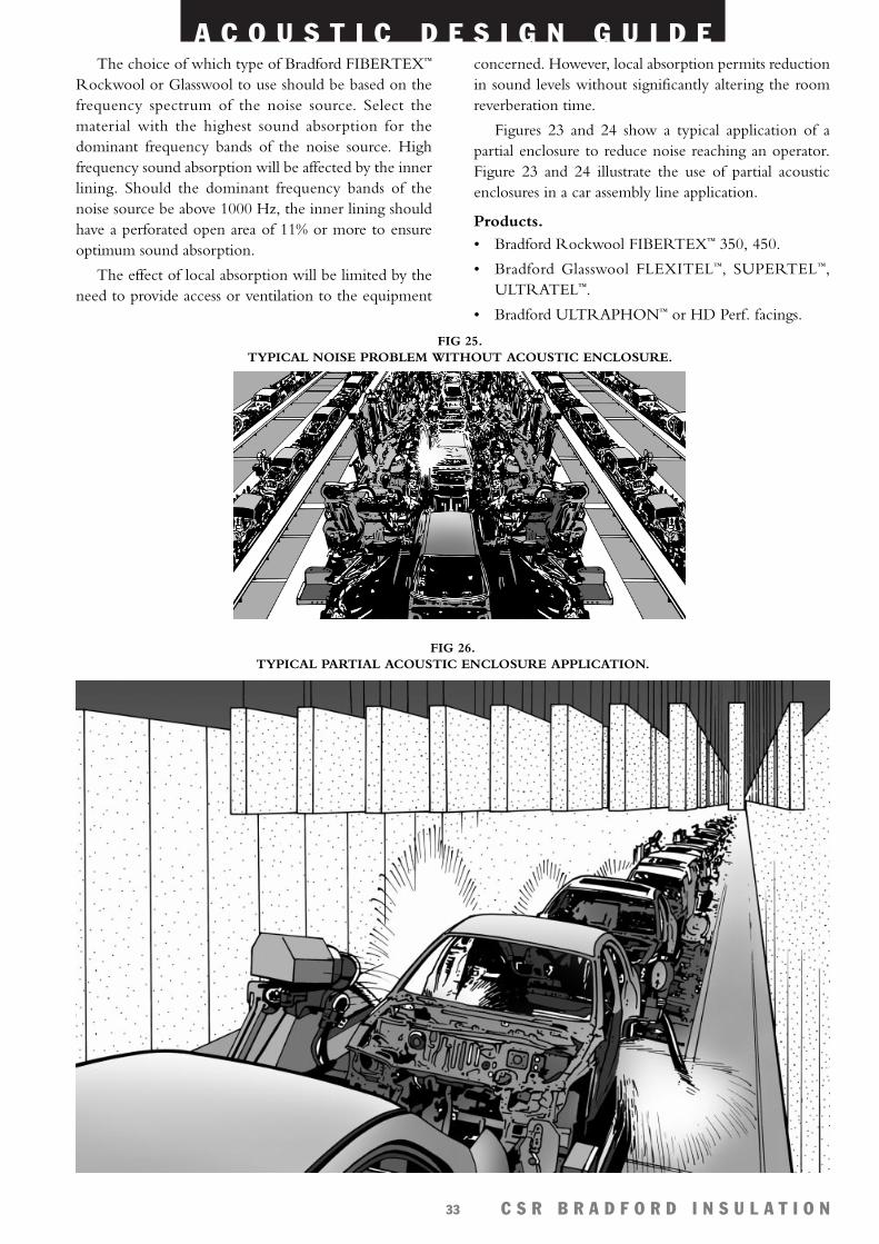
The choice of which type of Bradford FIBERTEX™
Rockwool or Glasswool to use should be based on thefrequency spectrum of the noise source. Select thematerial with the highest sound absorption for thedominant frequency bands of the noise source. Highfrequency sound absorption will be affected by the innerlining. Should the dominant frequency bands of thenoise source be above 1000 Hz, the inner lining shouldhave a perforated open area of 11% or more to ensureoptimum sound absorption.
The effect of local absorption will be limited by theneed to provide access or ventilation to the equipment
concerned. However, local absorption permits reductionin sound levels without significantly altering the roomreverberation time.
Figures 23 and 24 show a typical application of apartial enclosure to reduce noise reaching an operator.Figure 23 and 24 illustrate the use of partial acousticenclosures in a car assembly line application.
Products.
• Bradford Rockwool FIBERTEX™ 350, 450.
• Bradford Glasswool FLEXITEL™, SUPERTEL™,ULTRATEL™.
• Bradford ULTRAPHON™ or HD Perf. facings.
FIG 25. TYPICAL NOISE PROBLEM WITHOUT ACOUSTIC ENCLOSURE.
FIG 26. TYPICAL PARTIAL ACOUSTIC ENCLOSURE APPLICATION.
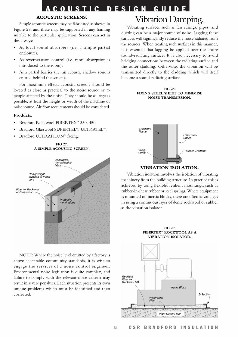
A C O U S T I C D E S I G N G U I D E
C S R B R A D F O R D I N S U L A T I O N34
ACOUSTIC SCREENS.Simple acoustic screens may be fabricated as shown in
Figure 27, and these may be supported in any framingsuitable to the particular application. Screens can act inthree ways:
• As local sound absorbers (i.e. a simple partialenclosure),
• As reverberation control (i.e. more absorption isintroduced to the room),
• As a partial barrier (i.e. an acoustic shadow zone iscreated behind the screen).
For maximum effect, acoustic screens should belocated as close as practical to the noise source or topeople affected by the noise. They should be as large aspossible, at least the height or width of the machine ornoise source. Air flow requirements should be considered.
Products.
• Bradford Rockwool FIBERTEX™ 350, 450.
• Bradford Glasswool SUPERTEL™, ULTRATEL™.
• Bradford ULTRAPHON™ facing.
NOTE: Where the noise level emitted by a factory isabove acceptable community standards, it is wise toengage the services of a noise control engineer.Environmental noise legislation is quite complex, andfailure to comply with the relevant noise criteria mayresult in severe penalties. Each situation presents its ownunique problems which must be identified and thencorrected.
Vibration Damping.Vibrating surfaces such as fan casings, pipes, and
ducting can be a major source of noise. Lagging thesesurfaces will significantly reduce the noise radiated fromthe sources. When treating such surfaces in this manner,it is essential that lagging be applied over the entiresound-radiating surface. It is also necessary to avoidbridging connections between the radiating surface andthe outer cladding. Otherwise, the vibration will betransmitted directly to the cladding which will itselfbecome a sound-radiating surface.
VIBRATION ISOLATION.Vibration isolation involves the isolation of vibrating
machinery from the building structure. In practice this isachieved by using flexible, resilient mountings, such asrubber-in-shear rubber or steel springs. Where equipmentis mounted on inertia blocks, there are often advantagesin using a continuous layer of dense rockwool or rubberas the vibration isolator.
EnclosureFrame
FixingScrew
Other steelSheet
Rubber Grommet
FIG 28. FIXING STEEL SHEET TO MINIMISE
NOISE TRANSMISSION.
ResilientFibertex Rockwool HD
Inertia Block
WaterproofFilm
Z-Section
Plant Room Floor
FIG 29. FIBERTEX™ ROCKWOOL AS A
VIBRATION ISOLATOR.
Decorative,non-reflectivefabric
Heavyweightplywood or metalcore
Fibertex Rockwoolor Glasswool
Protectivemetal edges
FIG 27. A SIMPLE ACOUSTIC SCREEN.
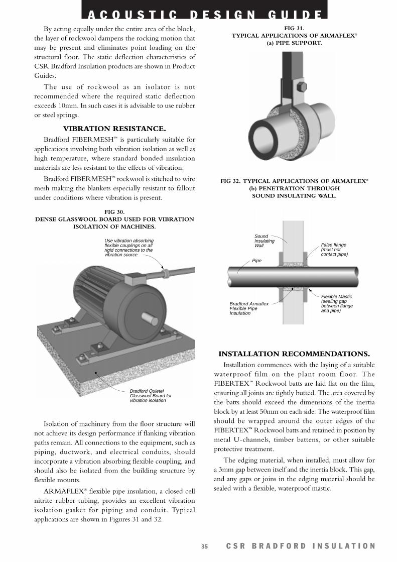
A C O U S T I C D E S I G N G U I D E
C S R B R A D F O R D I N S U L A T I O N35
By acting equally under the entire area of the block,the layer of rockwool dampens the rocking motion thatmay be present and eliminates point loading on thestructural floor. The static deflection characteristics ofCSR Bradford Insulation products are shown in ProductGuides.
The use of rockwool as an isolator is notrecommended where the required static deflectionexceeds 10mm. In such cases it is advisable to use rubberor steel springs.
VIBRATION RESISTANCE.Bradford FIBERMESH™ is particularly suitable for
applications involving both vibration isolation as well ashigh temperature, where standard bonded insulationmaterials are less resistant to the effects of vibration.
Bradford FIBERMESH™ rockwool is stitched to wiremesh making the blankets especially resistant to falloutunder conditions where vibration is present.
Isolation of machinery from the floor structure willnot achieve its design performance if flanking vibrationpaths remain. All connections to the equipment, such aspiping, ductwork, and electrical conduits, shouldincorporate a vibration absorbing flexible coupling, andshould also be isolated from the building structure byflexible mounts.
ARMAFLEX® flexible pipe insulation, a closed cellnitrite rubber tubing, provides an excellent vibrationisolation gasket for piping and conduit. Typicalapplications are shown in Figures 31 and 32.
INSTALLATION RECOMMENDATIONS.Installation commences with the laying of a suitable
waterproof film on the plant room floor. TheFIBERTEX™ Rockwool batts are laid flat on the film,ensuring all joints are tightly butted. The area covered bythe batts should exceed the dimensions of the inertiablock by at least 50mm on each side. The waterproof filmshould be wrapped around the outer edges of theFIBERTEX™ Rockwool batts and retained in position bymetal U-channels, timber battens, or other suitableprotective treatment.
The edging material, when installed, must allow fora 3mm gap between itself and the inertia block. This gap,and any gaps or joins in the edging material should besealed with a flexible, waterproof mastic.
Bradford Quietel Glasswool Board for vibration isolation
Use vibration absorbing flexible couplings on all rigid connections to the vibration source
FIG 30. DENSE GLASSWOOL BOARD USED FOR VIBRATION
ISOLATION OF MACHINES.
FIG 31. TYPICAL APPLICATIONS OF ARMAFLEX®
(a) PIPE SUPPORT.
SoundInsulatingWall False flange
(must notcontact pipe)
Bradford Armaflex Flexible Pipe Insulation
Flexible Mastic (sealing gapbetween flange and pipe)
Pipe
FIG 32. TYPICAL APPLICATIONS OF ARMAFLEX®
(b) PENETRATION THROUGH SOUND INSULATING WALL.
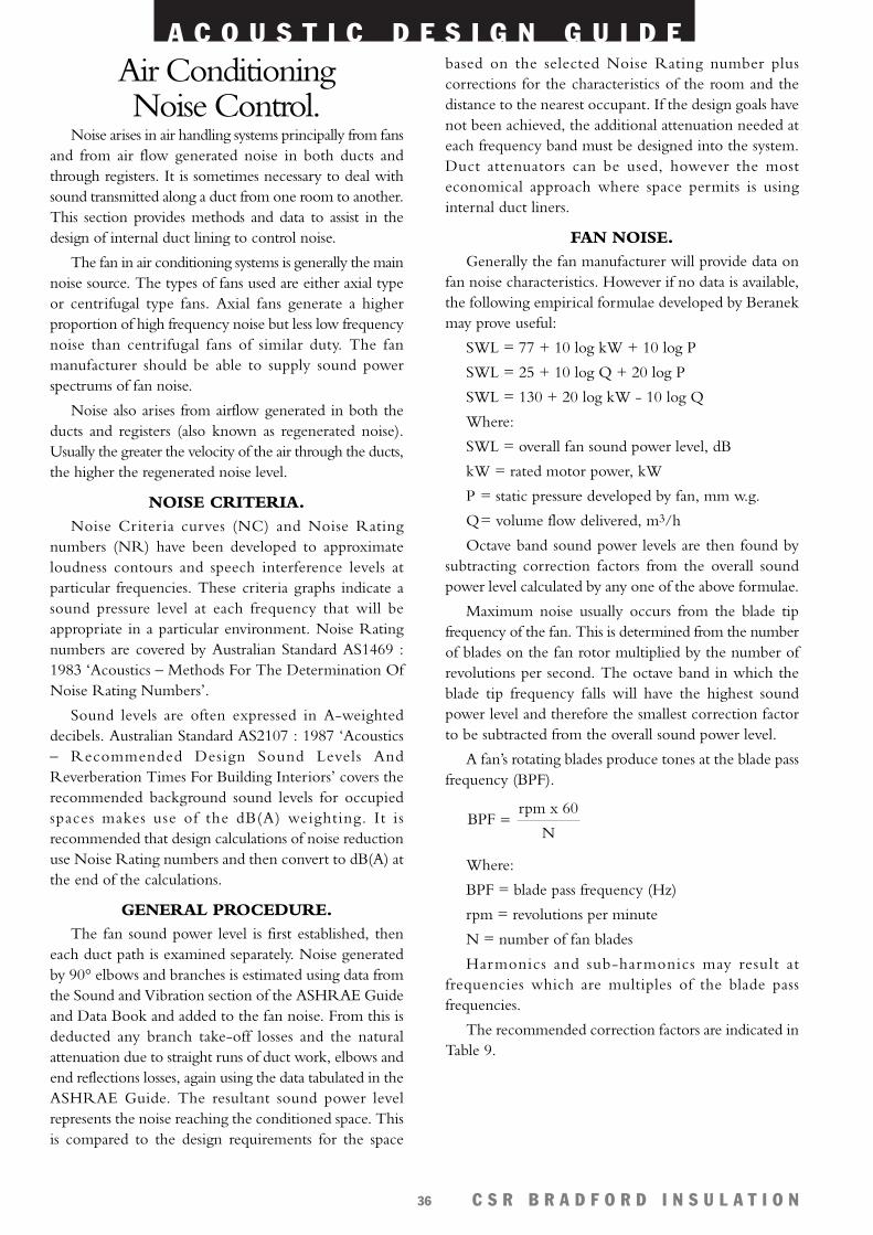
A C O U S T I C D E S I G N G U I D E
C S R B R A D F O R D I N S U L A T I O N36
Air ConditioningNoise Control.
Noise arises in air handling systems principally from fansand from air flow generated noise in both ducts andthrough registers. It is sometimes necessary to deal withsound transmitted along a duct from one room to another.This section provides methods and data to assist in thedesign of internal duct lining to control noise.
The fan in air conditioning systems is generally the mainnoise source. The types of fans used are either axial typeor centrifugal type fans. Axial fans generate a higherproportion of high frequency noise but less low frequencynoise than centrifugal fans of similar duty. The fanmanufacturer should be able to supply sound powerspectrums of fan noise.
Noise also arises from airflow generated in both theducts and registers (also known as regenerated noise).Usually the greater the velocity of the air through the ducts,the higher the regenerated noise level.
NOISE CRITERIA.Noise Criteria curves (NC) and Noise Rating
numbers (NR) have been developed to approximateloudness contours and speech interference levels atparticular frequencies. These criteria graphs indicate asound pressure level at each frequency that will beappropriate in a particular environment. Noise Ratingnumbers are covered by Australian Standard AS1469 :1983 ‘Acoustics – Methods For The Determination OfNoise Rating Numbers’.
Sound levels are often expressed in A-weighteddecibels. Australian Standard AS2107 : 1987 ‘Acoustics– Recommended Design Sound Levels AndReverberation Times For Building Interiors’ covers therecommended background sound levels for occupiedspaces makes use of the dB(A) weighting. It isrecommended that design calculations of noise reductionuse Noise Rating numbers and then convert to dB(A) atthe end of the calculations.
GENERAL PROCEDURE.The fan sound power level is first established, then
each duct path is examined separately. Noise generatedby 90° elbows and branches is estimated using data fromthe Sound and Vibration section of the ASHRAE Guideand Data Book and added to the fan noise. From this isdeducted any branch take-off losses and the naturalattenuation due to straight runs of duct work, elbows andend reflections losses, again using the data tabulated in theASHRAE Guide. The resultant sound power levelrepresents the noise reaching the conditioned space. Thisis compared to the design requirements for the space
based on the selected Noise Rating number pluscorrections for the characteristics of the room and thedistance to the nearest occupant. If the design goals havenot been achieved, the additional attenuation needed ateach frequency band must be designed into the system.Duct attenuators can be used, however the mosteconomical approach where space permits is usinginternal duct liners.
FAN NOISE.Generally the fan manufacturer will provide data on
fan noise characteristics. However if no data is available,the following empirical formulae developed by Beranekmay prove useful:
SWL = 77 + 10 log kW + 10 log P
SWL = 25 + 10 log Q + 20 log P
SWL = 130 + 20 log kW - 10 log Q
Where:
SWL = overall fan sound power level, dB
kW = rated motor power, kW
P = static pressure developed by fan, mm w.g.
Q= volume flow delivered, m3/h
Octave band sound power levels are then found bysubtracting correction factors from the overall soundpower level calculated by any one of the above formulae.
Maximum noise usually occurs from the blade tipfrequency of the fan. This is determined from the numberof blades on the fan rotor multiplied by the number ofrevolutions per second. The octave band in which theblade tip frequency falls will have the highest soundpower level and therefore the smallest correction factorto be subtracted from the overall sound power level.
A fan’s rotating blades produce tones at the blade passfrequency (BPF).
Where:
BPF = blade pass frequency (Hz)
rpm = revolutions per minute
N = number of fan blades
Harmonics and sub-harmonics may result atfrequencies which are multiples of the blade passfrequencies.
The recommended correction factors are indicated inTable 9.
rpm x 60
NBPF =
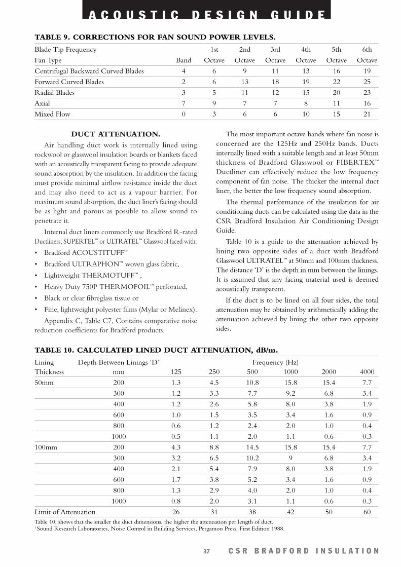
DUCT ATTENUATION.Air handling duct work is internally lined using
rockwool or glasswool insulation boards or blankets facedwith an acoustically transparent facing to provide adequatesound absorption by the insulation. In addition the facingmust provide minimal airflow resistance inside the ductand may also need to act as a vapour barrier. Formaximum sound absorption, the duct liner’s facing shouldbe as light and porous as possible to allow sound topenetrate it.
Internal duct liners commonly use Bradford R-ratedDuctliners, SUPERTEL™ or ULTRATEL™ Glasswool faced with:
• Bradford ACOUSTITUFF™
• Bradford ULTRAPHON™ woven glass fabric,
• Lightweight THERMOTUFF™ ,
• Heavy Duty 750P THERMOFOIL™ perforated,
• Black or clear fibreglass tissue or
• Fine, lightweight polyester films (Mylar or Melinex).
Appendix C, Table C7, Contains comparative noisereduction coefficients for Bradford products.
A C O U S T I C D E S I G N G U I D E
C S R B R A D F O R D I N S U L A T I O N37
The most important octave bands where fan noise isconcerned are the 125Hz and 250Hz bands. Ductsinternally lined with a suitable length and at least 50mmthickness of Bradford Glasswool or FIBERTEX™
Ductliner can effectively reduce the low frequencycomponent of fan noise. The thicker the internal ductliner, the better the low frequency sound absorption.
The thermal performance of the insulation for airconditioning ducts can be calculated using the data in theCSR Bradford Insulation Air Conditioning DesignGuide.
Table 10 is a guide to the attenuation achieved bylining two opposite sides of a duct with BradfordGlasswool ULTRATEL™ at 50mm and 100mm thickness.The distance ‘D’ is the depth in mm between the linings.It is assumed that any facing material used is deemedacoustically transparent.
If the duct is to be lined on all four sides, the totalattenuation may be obtained by arithmetically adding theattenuation achieved by lining the other two oppositesides.
TABLE 9. CORRECTIONS FOR FAN SOUND POWER LEVELS.
Blade Tip Frequency 1st 2nd 3rd 4th 5th 6th
Fan Type Band Octave Octave Octave Octave Octave Octave
Centrifugal Backward Curved Blades 4 6 9 11 13 16 19
Forward Curved Blades 2 6 13 18 19 22 25
Radial Blades 3 5 11 12 15 20 23
Axial 7 9 7 7 8 11 16
Mixed Flow 0 3 6 6 10 15 21
TABLE 10. CALCULATED LINED DUCT ATTENUATION, dB/m.
Lining Depth Between Linings ‘D’ Frequency (Hz)Thickness mm 125 250 500 1000 2000 4000
50mm 200 1.3 4.5 10.8 15.8 15.4 7.7
300 1.2 3.3 7.7 9.2 6.8 3.4
400 1.2 2.6 5.8 8.0 3.8 1.9
600 1.0 1.5 3.5 3.4 1.6 0.9
800 0.6 1.2 2.4 2.0 1.0 0.4
1000 0.5 1.1 2.0 1.1 0.6 0.3
100mm 200 4.3 8.8 14.5 15.8 15.4 7.7
300 3.2 6.5 10.2 9 6.8 3.4
400 2.1 5.4 7.9 8.0 3.8 1.9
600 1.7 3.8 5.2 3.4 1.6 0.9
800 1.3 2.9 4.0 2.0 1.0 0.4
1000 0.8 2.0 3.1 1.1 0.6 0.3
Limit of Attenuation 26 31 38 42 50 60Table 10, shows that the smaller the duct dimensions, the higher the attenuation per length of duct. 1 Sound Research Laboratories, Noise Control in Building Services, Pergamon Press, First Edition 1988.
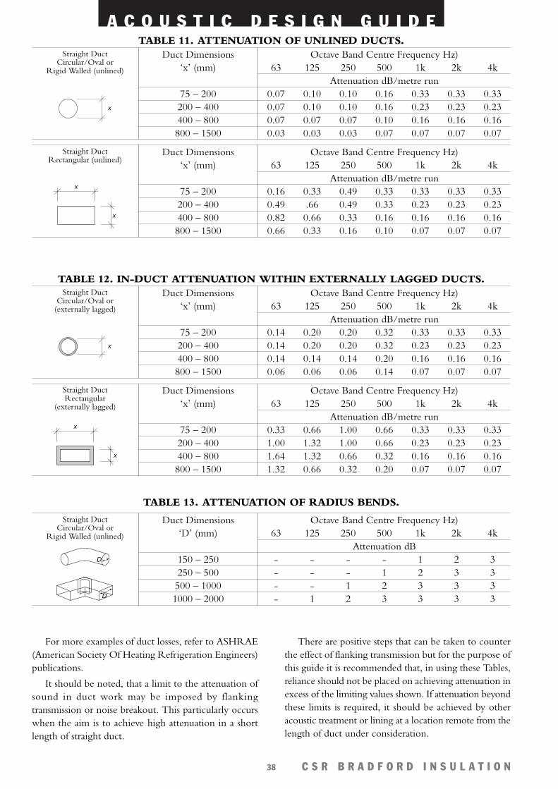
A C O U S T I C D E S I G N G U I D E
C S R B R A D F O R D I N S U L A T I O N38
For more examples of duct losses, refer to ASHRAE(American Society Of Heating Refrigeration Engineers)publications.
It should be noted, that a limit to the attenuation ofsound in duct work may be imposed by flankingtransmission or noise breakout. This particularly occurswhen the aim is to achieve high attenuation in a shortlength of straight duct.
There are positive steps that can be taken to counterthe effect of flanking transmission but for the purpose ofthis guide it is recommended that, in using these Tables,reliance should not be placed on achieving attenuation inexcess of the limiting values shown. If attenuation beyondthese limits is required, it should be achieved by otheracoustic treatment or lining at a location remote from thelength of duct under consideration.
Duct Dimensions‘x’ (mm)
75 – 200200 – 400400 – 800800 – 1500
Octave Band Centre Frequency Hz)63 125 250 500 1k 2k 4k
Attenuation dB/metre run0.07 0.10 0.10 0.16 0.33 0.33 0.330.07 0.10 0.10 0.16 0.23 0.23 0.230.07 0.07 0.07 0.10 0.16 0.16 0.160.03 0.03 0.03 0.07 0.07 0.07 0.07
x
Straight DuctCircular/Oval or
Rigid Walled (unlined)
TABLE 11. ATTENUATION OF UNLINED DUCTS.
Duct Dimensions‘x’ (mm)
75 – 200200 – 400400 – 800800 – 1500
Octave Band Centre Frequency Hz)63 125 250 500 1k 2k 4k
Attenuation dB/metre run0.16 0.33 0.49 0.33 0.33 0.33 0.330.49 .66 0.49 0.33 0.23 0.23 0.230.82 0.66 0.33 0.16 0.16 0.16 0.160.66 0.33 0.16 0.10 0.07 0.07 0.07
x
x
Straight DuctRectangular (unlined)
Duct Dimensions‘x’ (mm)
75 – 200200 – 400400 – 800800 – 1500
Octave Band Centre Frequency Hz)63 125 250 500 1k 2k 4k
Attenuation dB/metre run0.14 0.20 0.20 0.32 0.33 0.33 0.330.14 0.20 0.20 0.32 0.23 0.23 0.230.14 0.14 0.14 0.20 0.16 0.16 0.160.06 0.06 0.06 0.14 0.07 0.07 0.07
x
Straight DuctCircular/Oval or
(externally lagged)
TABLE 12. IN-DUCT ATTENUATION WITHIN EXTERNALLY LAGGED DUCTS.
Duct Dimensions‘x’ (mm)
75 – 200200 – 400400 – 800800 – 1500
Octave Band Centre Frequency Hz)63 125 250 500 1k 2k 4k
Attenuation dB/metre run0.33 0.66 1.00 0.66 0.33 0.33 0.331.00 1.32 1.00 0.66 0.23 0.23 0.231.64 1.32 0.66 0.32 0.16 0.16 0.161.32 0.66 0.32 0.20 0.07 0.07 0.07
x
x
Straight DuctRectangular
(externally lagged)
Duct Dimensions‘D’ (mm)
150 – 250250 – 500500 – 10001000 – 2000
Octave Band Centre Frequency Hz)63 125 250 500 1k 2k 4k
Attenuation dB- - - - 1 2 3- - - 1 2 3 3- - 1 2 3 3 3- 1 2 3 3 3 3
D
Straight DuctCircular/Oval or
Rigid Walled (unlined)
TABLE 13. ATTENUATION OF RADIUS BENDS.
D
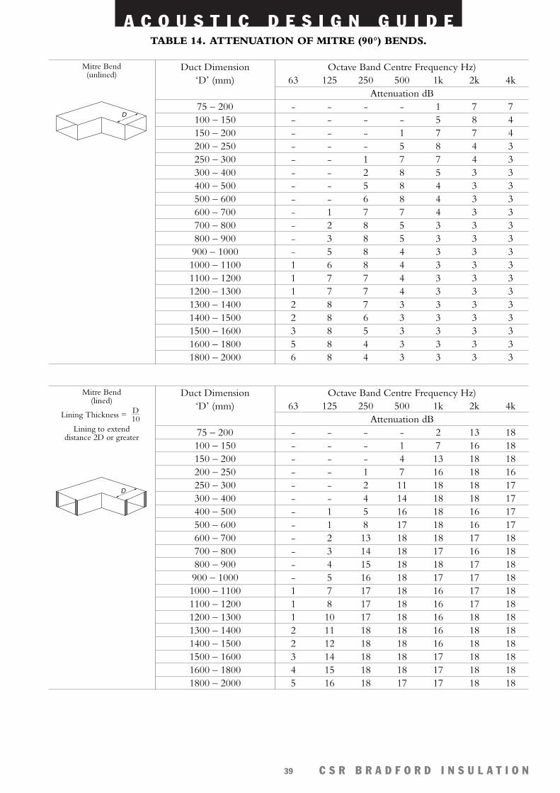
A C O U S T I C D E S I G N G U I D E
C S R B R A D F O R D I N S U L A T I O N39
Duct Dimension‘D’ (mm)
75 – 200100 – 150150 – 200200 – 250250 – 300300 – 400400 – 500500 – 600600 – 700700 – 800800 – 900900 – 10001000 – 11001100 – 12001200 – 13001300 – 14001400 – 15001500 – 16001600 – 18001800 – 2000
Octave Band Centre Frequency Hz)63 125 250 500 1k 2k 4k
Attenuation dB- - - - 1 7 7- - - - 5 8 4- - - 1 7 7 4- - - 5 8 4 3- - 1 7 7 4 3- - 2 8 5 3 3- - 5 8 4 3 3- - 6 8 4 3 3- 1 7 7 4 3 3- 2 8 5 3 3 3- 3 8 5 3 3 3- 5 8 4 3 3 31 6 8 4 3 3 31 7 7 4 3 3 31 7 7 4 3 3 32 8 7 3 3 3 32 8 6 3 3 3 33 8 5 3 3 3 35 8 4 3 3 3 36 8 4 3 3 3 3
D
Mitre Bend(unlined)
TABLE 14. ATTENUATION OF MITRE (90°) BENDS.
Duct Dimension‘D’ (mm)
75 – 200100 – 150150 – 200200 – 250250 – 300300 – 400400 – 500500 – 600600 – 700700 – 800800 – 900900 – 10001000 – 11001100 – 12001200 – 13001300 – 14001400 – 15001500 – 16001600 – 18001800 – 2000
Octave Band Centre Frequency Hz)63 125 250 500 1k 2k 4k
Attenuation dB- - - - 2 13 18- - - 1 7 16 18- - - 4 13 18 18- - 1 7 16 18 16- - 2 11 18 18 17- - 4 14 18 18 17- 1 5 16 18 16 17- 1 8 17 18 16 17- 2 13 18 18 17 18- 3 14 18 17 16 18- 4 15 18 18 17 18- 5 16 18 17 17 181 7 17 18 16 17 181 8 17 18 16 17 181 10 17 18 16 18 182 11 18 18 16 18 182 12 18 18 16 18 183 14 18 18 17 18 184 15 18 18 17 18 185 16 18 17 17 18 18
D
Mitre Bend(lined)
Lining Thickness =
Lining to extend distance 2D or greater
D10
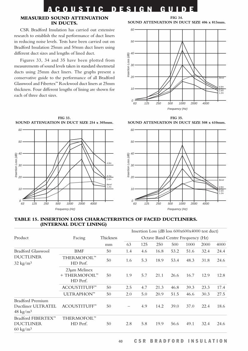
A C O U S T I C D E S I G N G U I D E
C S R B R A D F O R D I N S U L A T I O N40
MEASURED SOUND ATTENUATIONIN DUCTS.
CSR Bradford Insulation has carried out extensiveresearch to establish the real performance of duct linersin reducing noise levels. Tests have been carried out onBradford Insulation 25mm and 50mm duct liners usingdifferent duct sizes and lengths of lined duct.
Figures 33, 34 and 35 have been plotted frommeasurements of sound levels taken in standard sheetmetalducts using 25mm duct liners. The graphs present aconservative guide to the performance of all BradfordGlasswool and Fibertex™ Rockwool duct liners at 25mmthickness. Four different lengths of lining are shown foreach of three duct sizes.
63 125 250 500 1000 2000 40000
10
20
30
40
50
60
Frequency (Hz)
Inse
rtio
n Lo
ss (
dB)
4.9m3.7m2.4m
Bend
1.2m
FIG 35. SOUND ATTENUATION IN DUCT SIZE 508 x 610mm.
63 125 250 500 1000 2000 40000
10
20
30
40
50
60
Frequency (Hz)
Inse
rtio
n Lo
ss (
dB)
4.9m
3.7m
2.4m
Bend1.2m
FIG 33. SOUND ATTENUATION IN DUCT SIZE 254 x 305mm.
63 125 250 500 1000 2000 40000
10
20
30
40
50
60
Frequency (Hz)
Inse
rtio
n Lo
ss (
dB)
4.9m3.7m2.4m
Bend
1.2m
FIG 34. SOUND ATTENUATION IN DUCT SIZE 406 x 813mm.
Insertion Loss (dB loss 600x600x4000 test duct)
Product Facing Thickness Octave Band Centre Frequency (Hz)
mm 63 125 250 500 1000 2000 4000
Bradford Glasswool BMF 50 1.4 4.6 16.8 53.2 51.6 32.4 24.4DUCTLINER THERMOFOIL™
32 kg/m3 HD Perf.50 1.6 5.3 18.9 53.4 48.3 31.8 24.6
23µm Melinex+ THERMOFOIL™ 50 1.9 5.7 21.1 26.6 16.7 12.9 12.8
HD Perf.
ACOUSTITUFF™ 50 2.5 4.7 21.3 46.8 39.3 23.3 17.4
ULTRAPHON™ 50 2.0 5.0 20.9 51.5 46.6 30.3 27.5
Bradford Premium Ductliner ULTRATEL ACOUSTITUFF™ 50 – 4.9 14.2 39.0 37.0 22.4 18.648 kg/m3
Bradford FIBERTEX™ THERMOFOIL™
DUCTLINER HD Perf. 50 2.8 5.8 19.9 56.6 49.1 32.4 24.660 kg/m3
TABLE 15. INSERTION LOSS CHARACTERISTICS OF FACED DUCTLINERS. (INTERNAL DUCT LINING)
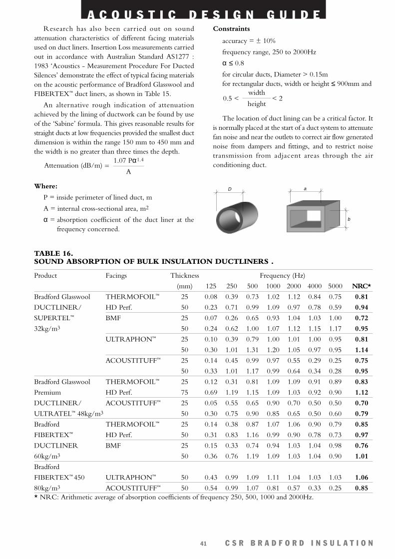
A C O U S T I C D E S I G N G U I D E
C S R B R A D F O R D I N S U L A T I O N41
Research has also been carr ied out on soundattenuation characteristics of different facing materialsused on duct liners. Insertion Loss measurements carriedout in accordance with Australian Standard AS1277 :1983 ‘Acoustics - Measurement Procedure For DuctedSilences’ demonstrate the effect of typical facing materialson the acoustic performance of Bradford Glasswool andFIBERTEX™ duct liners, as shown in Table 15.
An alternative rough indication of attenuationachieved by the lining of ductwork can be found by useof the ‘Sabine’ formula. This gives reasonable results forstraight ducts at low frequencies provided the smallest ductdimension is within the range 150 mm to 450 mm andthe width is no greater than three times the depth.
Where:
P = inside perimeter of lined duct, m
A = internal cross-sectional area, m2
α = absorption coefficient of the duct liner at thefrequency concerned.
1.07 Pα1.4
AAttenuation (dB/m) =
Constraints
accuracy = ± 10%
frequency range, 250 to 2000Hz
α ≤ 0.8
for circular ducts, Diameter > 0.15mfor rectangular ducts, width or height ≤ 900mm and
The location of duct lining can be a critical factor. Itis normally placed at the start of a duct system to attenuatefan noise and near the outlets to correct air flow generatednoise from dampers and fittings, and to restrict noisetransmission from adjacent areas through the airconditioning duct.
< 2width
height0.5 <
D a
b
TABLE 16. SOUND ABSORPTION OF BULK INSULATION DUCTLINERS .
Product Facings Thickness Frequency (Hz)
(mm) 125 250 500 1000 2000 4000 5000 NRC*
Bradford Glasswool THERMOFOIL™ 25 0.08 0.39 0.73 1.02 1.12 0.84 0.75 0.81
DUCTLINER/ HD Perf. 50 0.23 0.71 0.99 1.09 0.97 0.78 0.59 0.94
SUPERTEL™ BMF 25 0.07 0.26 0.65 0.93 1.04 1.03 1.00 0.72
32kg/m3 50 0.24 0.62 1.00 1.07 1.12 1.15 1.17 0.95
ULTRAPHON™ 25 0.10 0.39 0.79 1.00 1.01 1.00 0.95 0.81
50 0.30 1.01 1.31 1.20 1.05 0.97 0.95 1.14
ACOUSTITUFF™ 25 0.14 0.45 0.99 0.97 0.55 0.29 0.25 0.75
50 0.33 1.01 1.17 0.99 0.64 0.34 0.28 0.95
Bradford Glasswool THERMOFOIL™ 25 0.12 0.31 0.81 1.09 1.09 0.91 0.89 0.83
Premium HD Perf. 75 0.69 1.19 1.15 1.09 1.03 0.92 0.90 1.12
DUCTLINER/ ACOUSTITUFF™ 25 0.05 0.55 0.65 0.90 0.70 0.50 0.50 0.70
ULTRATEL™ 48kg/m3 50 0.30 0.75 0.90 0.85 0.65 0.50 0.60 0.79
Bradford THERMOFOIL™ 25 0.14 0.38 0.87 1.07 1.06 0.90 0.79 0.85
FIBERTEX™ HD Perf. 50 0.31 0.83 1.16 0.99 0.90 0.78 0.73 0.97
DUCTLINER BMF 25 0.15 0.33 0.74 0.94 1.03 1.04 0.98 0.76
60kg/m3 50 0.36 0.76 1.19 1.09 1.03 1.04 0.90 1.01
Bradford
FIBERTEX™ 450 ULTRAPHON™ 50 0.43 0.99 1.09 1.11 1.04 1.03 1.03 1.06
80kg/m3 ACOUSTITUFF™ 50 0.54 0.99 1.07 0.81 0.57 0.33 0.25 0.85* NRC: Arithmetic average of absorption coefficients of frequency 250, 500, 1000 and 2000Hz.
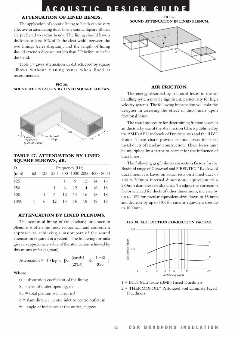
A C O U S T I C D E S I G N G U I D E
C S R B R A D F O R D I N S U L A T I O N42
AIR FRICTION.The energy absorbed by frictional losses in the air
handling system may be significant, particularly for highvelocity systems. The following information will assist thedesigner in assessing the effect of duct liners uponfrictional losses.
The usual procedure for determining friction losses inair ducts is by use of the Air Friction Charts published bythe ASHRAE Handbook of Fundamentals and the IHVEGuide. These charts provide friction losses for sheetmetal ducts of standard construction. These losses mustbe multiplied by a factor to correct for the influence ofduct liners.
The following graph shows correction factors for theBradford range of Glasswool and FIBERTEX™ Rockwoolduct liners. It is based on actual tests on a lined duct of460 x 200mm internal dimensions, equivalent to a280mm diameter circular duct. To adjust the correctionfactor selected for ducts of other dimensions, increase byup to 10% for circular equivalent sizes down to 150mmand decrease by up to 10% for circular equivalent sizes upto 1000mm.
ATTENUATION OF LINED BENDS.The application of acoustic lining to bends can be very
effective in attenuating duct-borne sound. Square elbowsare preferred to radius bends. The lining should have athickness at least 10% of D, the clear width between thetwo linings (refer diagram), and the length of liningshould extend a distance not less than 2D before and afterthe bend.
Table 17 gives attenuation in dB achieved by squareelbows without turning vanes when lined asrecommended.
TABLE 17. ATTENUATION BY LINEDSQUARE ELBOWS, dB.
D Frequency (Hz)(mm) 63 125 250 500 1000 2000 4000 8000
125 1 6 12 14 16
250 1 6 12 14 16 18
500 1 6 12 14 16 18 18
1000 1 6 12 14 16 18 18 18
ATTENUATION BY LINED PLENUMS.The acoustical lining of fan discharge and suction
plenums is often the most economical and convenientapproach to achieving a major part of the soundattenuation required in a system. The following formulagives an approximate value of the attenuation achieved bythis means (refer diagram).
Attenuation =
Where:
α = absorption coefficient of the lining
So = area of outlet opening, m2
Sw = total plenum wall area, m2
d = slant distance, centre inlet to centre outlet, m
θ = angle of incidence at the outlet, degrees.
]1 – ααSw
+ So(cosθ)(2πd2)
[So10 log10
2DD
LiningThickness(10% of D min.)
Acoustic Lining
FIG 36.SOUND ATTENUATION BY LINED SQUARE ELBOWS.
θ
d
FIG 37. SOUND ATTENUATION IN LINED PLENUM.
1
2
20108654321
1.5
2.0
Cor
rect
ion
Fact
or
Air Velocity (m/s)
FIG 38. AIR FRICTION CORRECTION FACTOR.
1 = Black Matt tissue (BMF) Faced Ductliners.2 = THERMOFOIL™ Perforated Foil Laminate Faced
Ductliners.
A C O U S T I C D E S I G N G U I D E
C S R B R A D F O R D I N S U L A T I O N43
RESISTANCE TO AIR EROSION ANDRECOMMENDED VELOCITIES
Bradford Glasswool and FIBERTEX™ Rockwoolductliners have been tested for surface erosion at extremevelocities by the quantitative method developed by theCSR Building Materials Research Laboratories, based onUnderwriters Laboratory Standard UL181-1990. Theproducts were subject to velocities up to 40m/s and thena safety factor of 0.4 applied in accordance with theUnderwriters Laboratory test. On the basis of theseresults and typical air friction correction factors fromASHRAE, the following maximum design velocities arerecommended.
TABLE 18. MAXIMUM DESIGN VELOCITY.
Product Maximum DesignVelocity (m/s)
Bradford GlasswoolCovered with Perforated Metal 23
Faced with Perforated Foil 18
Faced with Black Matt Tissue (BMF) 22Faced with ACOUSTITUFF™ 30Faced with ULTRAPHON™ 26
Bradford FIBERTEX™ RockwoolFIBERTEX™ Ductliner CF coveredwith Perforated Metal 23
FIBERTEX™ Ductliner with Perforated Foil18
FIBERTEX™ Ductliner faced withBlack Matt Tissue (BMF) 22
EXTERNAL DUCT LAGGING.External lining (lagging) of air conditioning ducts
with foil faced rockwool or glasswool reduces ductbreakout noise by damping the duct. Some of the noisewhich breaks out through the lagged duct is absorbed bythe surrounding insulation. The sound attenuationachieved inside the duct is also enhanced by duct laggingparticularly at low frequencies, up to about 500Hz.
Air handling ducts are commonly lagged using:
• Bradford FIBERTEX™ Rockwool Ductwrap
• Bradford Glasswool MULTITEL™ or FLEXITEL™
with Medium or Heavy Duty THERMOFOIL™.
• Bradford Glasswool THERMOGOLD™ Ductwrap.
DUCT BREAK OUT-NOISE.Noise breakout from ducts can occur from:
• Fan noise passing through the duct
• Aerodynamic noise (also know as re-generated noise),from obstructions fittings etc in the duct
• Turbulent airflow causing duct walls to vibrate andrumble radiating low frequency airborne noise.
Solutions to reduce noise breakout from ducts:
• Stiffer ducts (circular ducts are better than square orrectangular). External bracing of ducts increasesstiffness, however it can improve the radiationefficiency of the duct cancelling the benefit ofincreased stiffness.
• Using heavier material for duct walls and increasingdamping (ie. thicker steel sheeting).
• Adding damping (spray on or self adhesivecompounds).
• Acoustic lagging, preferably with a heavy limpimpervious layer isolated or decoupled from the ductwith either glasswool (such as BradfordACOUSTILAG™) or rockwool.
The solutions to reduce noise breaking out fromducts can be expensive. Therefore it is more cost effectiveto avoid noise break out problems than to try to correctthem later.
DUCT BREAK-IN NOISE.Noise inside ceiling plenums or from air conditioning
equipment, plant rooms etc, can break into ducts,particularly flexible ducts and then be carried into roomsor spaces below.
Flexible ducts, due to their light weight, flexibility,speed and ease of installation, are commonly used in airconditioning systems. Noise can more easily penetrateflexible ducts because of their lightweight nature.
To avoid break-in noise, the following can be used:
• Where possible, avoid ducts passing through noisyareas as this can significantly increase noise through theair conditioning system.
• Replace lightweight flexible ducts with heavierducting such as sheet steel.
• The flexible ducts can be enclosed in a solid enclosureconstructed from timber, plasterboard or sheet steel,etc.
Before enclosing flexible ducts, it should be noted thatnoise in the ceiling cavity will most likely penetrate theceiling. This will happen more so if lightweight lay-in tilesusing metal grids are used. Fixed plasterboard ceilings givebetter acoustic performance than lightweight ceiling tiles.
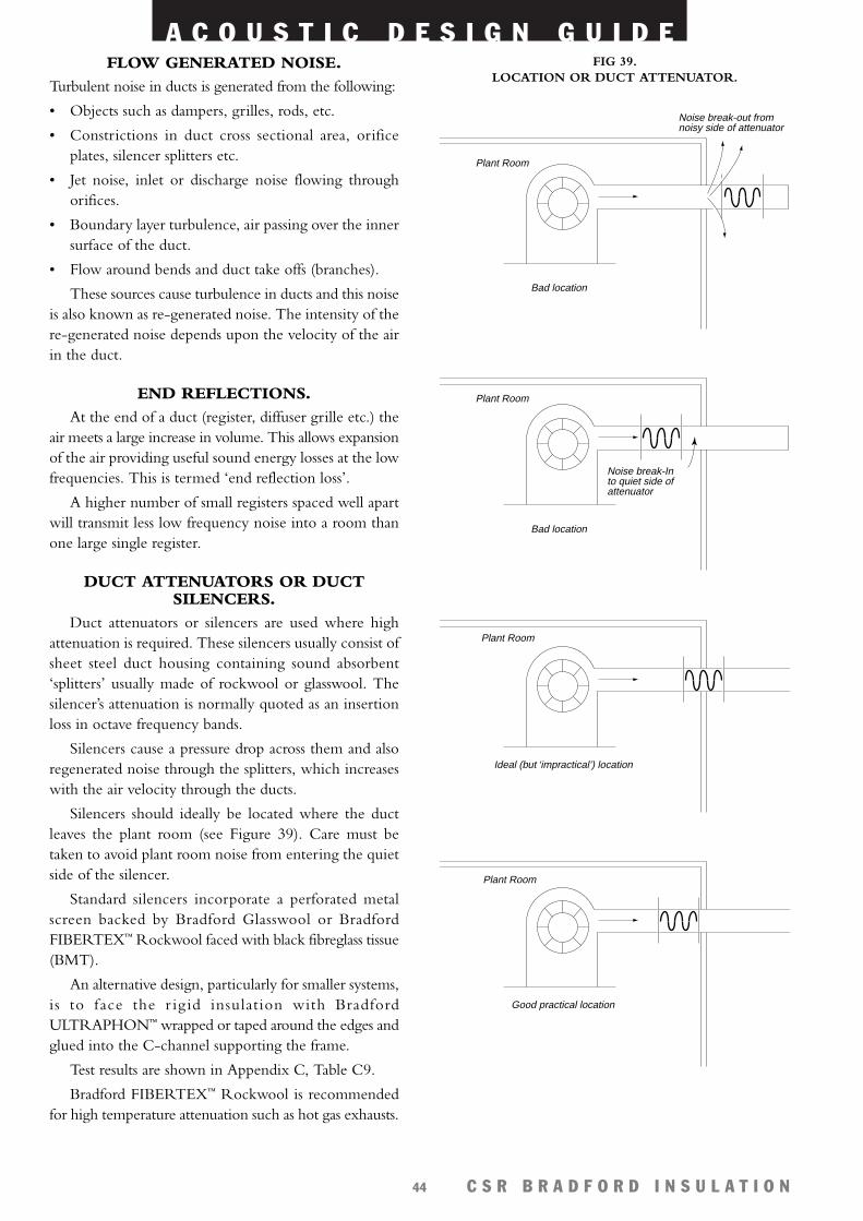
A C O U S T I C D E S I G N G U I D E
C S R B R A D F O R D I N S U L A T I O N44
FLOW GENERATED NOISE.Turbulent noise in ducts is generated from the following:
• Objects such as dampers, grilles, rods, etc.
• Constrictions in duct cross sectional area, orificeplates, silencer splitters etc.
• Jet noise, inlet or discharge noise flowing throughorifices.
• Boundary layer turbulence, air passing over the innersurface of the duct.
• Flow around bends and duct take offs (branches).
These sources cause turbulence in ducts and this noiseis also known as re-generated noise. The intensity of there-generated noise depends upon the velocity of the airin the duct.
END REFLECTIONS.At the end of a duct (register, diffuser grille etc.) the
air meets a large increase in volume. This allows expansionof the air providing useful sound energy losses at the lowfrequencies. This is termed ‘end reflection loss’.
A higher number of small registers spaced well apartwill transmit less low frequency noise into a room thanone large single register.
DUCT ATTENUATORS OR DUCTSILENCERS.
Duct attenuators or silencers are used where highattenuation is required. These silencers usually consist ofsheet steel duct housing containing sound absorbent‘splitters’ usually made of rockwool or glasswool. Thesilencer’s attenuation is normally quoted as an insertionloss in octave frequency bands.
Silencers cause a pressure drop across them and alsoregenerated noise through the splitters, which increaseswith the air velocity through the ducts.
Silencers should ideally be located where the ductleaves the plant room (see Figure 39). Care must betaken to avoid plant room noise from entering the quietside of the silencer.
Standard silencers incorporate a perforated metalscreen backed by Bradford Glasswool or BradfordFIBERTEX™ Rockwool faced with black fibreglass tissue(BMT).
An alternative design, particularly for smaller systems,is to face the r ig id insulation with BradfordULTRAPHON™ wrapped or taped around the edges andglued into the C-channel supporting the frame.
Test results are shown in Appendix C, Table C9.
Bradford FIBERTEX™ Rockwool is recommendedfor high temperature attenuation such as hot gas exhausts.
Plant Room
Noise break-out fromnoisy side of attenuator
Bad location
Bad location
Plant Room
Noise break-In to quiet side ofattenuator
Plant Room
Ideal (but ‘impractical’) location
Plant Room
Good practical location
FIG 39. LOCATION OR DUCT ATTENUATOR.
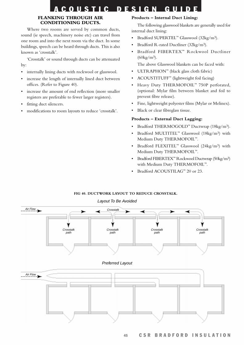
A C O U S T I C D E S I G N G U I D E
C S R B R A D F O R D I N S U L A T I O N45
FLANKING THROUGH AIRCONDITIONING DUCTS.
Where two rooms are served by common ducts,sound (ie speech, machinery noise etc) can travel fromone room and into the next room via the duct. In somebuildings, speech can be heard through ducts. This is alsoknown as ‘crosstalk’.
‘Crosstalk’ or sound through ducts can be attenuatedby:
• internally lining ducts with rockwool or glasswool.
• increase the length of internally lined duct betweenoffices. (Refer to Figure 40).
• increase the amount of end reflection (more smallerregisters are preferable to fewer larger registers).
• fitting duct silencers.
• modifications to room layouts to reduce ‘crosstalk’.
Air Flow
Crosstalkpath
Crosstalkpath
Crosstalkpath
Crosstalkpath
Air Flow
Layout To Be Avoided
Preferred Layout
Crosstalk
FIG 40. DUCTWORK LAYOUT TO REDUCE CROSSTALK.
Products – Internal Duct Lining:
The following glasswool blankets are generally used forinternal duct lining:
• Bradford SUPERTEL™ Glasswool (32kg/m3).
• Bradford R-rated Ductliner (32kg/m3).
• Bradford FIBERTEX™ Rockwool Ductliner(60kg/m3).
The above Glasswool blankets can be faced with:
• ULTRAPHON™ (black glass cloth fabric)
• ACOUSTITUFF™ (lightweight foil facing)
• Heavy Duty THERMOFOIL™ 750P perforated,(optional: Mylar film between blanket and foil toprevent fibre release).
• Fine, lightweight polyester films (Mylar or Melinex).
• Black or clear fibreglass tissue.
Products – External Duct Lagging:
• Bradford THERMOGOLD™ Ductwrap (18kg/m3).
• Bradford MULTITEL™ Glasswool (18kg/m3) withMedium Duty THERMOFOIL™.
• Bradford FLEXITEL™ Glasswool (24kg/m3) withMedium Duty THERMOFOIL™.
• Bradford FIBERTEX™ Rockwool Ductwrap (50kg/m3)with Medium Duty THERMOFOIL™.
• Bradford ACOUSTILAG™ 20 or 23.
A C O U S T I C D E S I G N G U I D E
C S R B R A D F O R D I N S U L A T I O N46
• Ceilings should include increased mass to increasetheir STC rating. Multi layers of CSR Gyprock®
plasterboard can be used with Bradford Rockwool orGlasswool Ceiling Batts above.
• Floors should be insulated with Bradford Floor Battsparticularly if the cinema room is upstairs. (seeFloor/Ceiling Noise Control Systems, Appendix B).
• Windows should be double glazed with preferablydifferent size laminated glass panes to provide betterdamping. Large air gaps between the glass panes, andproperly sealed around the perimeter of the frame alsoincreases the window’s acoustic rating. Laminatedsingle pane glass is the next best choice.
• Doors should be solid core timber or metal withgood quality door seals. Preferably double doors or aninsulated sound lock should be used.
Note that if the room has ducted air conditioning, thenflanking can occur through the ducting and sound can passinto the next room.
Bradford Products for –Walls:
• Bradford Rockwool or Glasswool Partition Batts.
• Bradford SoundScreen™.
Ceilings:
• Bradford Rockwool or Glasswool Ceiling Batts.
• Bradford Glasswool Ceiling Panel Overlays.
• Bradford Rockwool FIBERTEX™ 350, 450.
• Bradford Glasswool FLEXITEL™, SUPERTEL™,ULTRATEL™.
• Bradford Glasswool Absorption Blanket.
Home Cinema.The current trend in households today is the use of
timber floors or tiled floors which are hard andacoustically reflective. These together with reflectivewalls and ceilings result in long reverberation times notsuited to home cinema systems.
Under these circumstances, home cinema systemswill require more sound absorption in the room to lowerthe reverberation time closer to the optimum level suitedto amplified music and speech. Note that too muchabsorption will make the room ‘dead’ and result in poorerquality sound.
To lower the reverberation time of a room, install:
• Decorative fabric faced rockwool or glasswool absorberson the walls.
• Velour coated high density rockwool or glasswool onthe walls.
• Perforated timber, Gyprock® plasterboard or perforatedmetal pan ceiling with rockwool or glasswool insulationabove.
• Rugs, carpet, curtains and soft furniture in the room.
The acoustic reproduction of many modern homecinema systems is very good, and they can generate highlevels of bass sound which penetrates building materialsmore easily. Low frequency sound is also more difficultto absorb.
Therefore the home cinema system room may be asource of noise for others in the household or neighbours,particularly if the volume is loud. These rooms should be treated or ‘sound proofed’ ifthey are likely to cause disturbance to others. Thefollowing treatments should be considered:
• Brick veneer walls should use mutli-layers of CSRGyprock® Fyrchek™ or Soundchek™ plasterboard toadd mass and increase the STC of the walls. Ideally,the wall should have two separate studs with BradfordRockwool or Glasswool Partition Batts inside thecavity walls. Bradford batts inside cavity partitionscan increase the walls acoustic rating by STC 10. If thisis not possible then staggered studs or the widest studcavity available should be used and filled with BradfordRockwool or Glasswool Partition Batts.
Bradford Acoustic Solutions forSpecialty Applications.
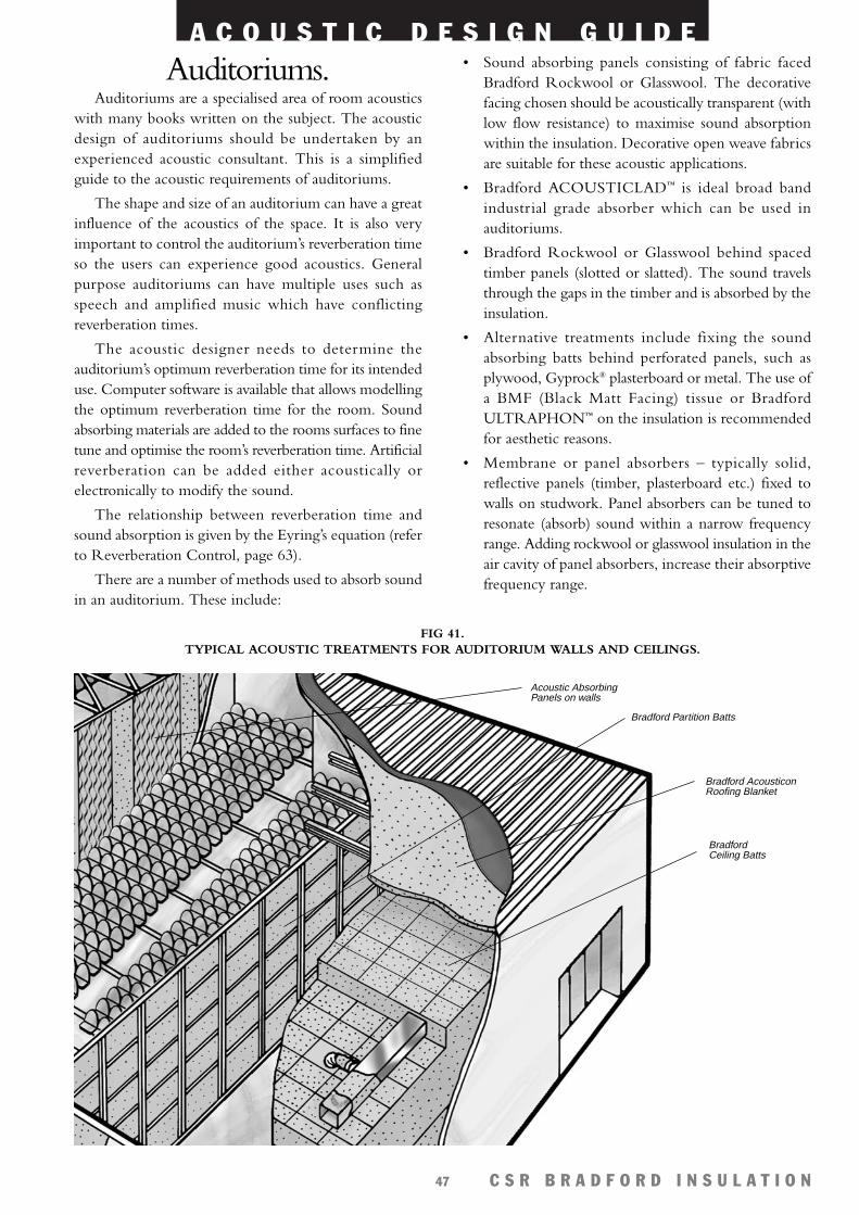
A C O U S T I C D E S I G N G U I D E
C S R B R A D F O R D I N S U L A T I O N47
Auditoriums.Auditoriums are a specialised area of room acoustics
with many books written on the subject. The acousticdesign of auditoriums should be undertaken by anexperienced acoustic consultant. This is a simplifiedguide to the acoustic requirements of auditoriums.
The shape and size of an auditorium can have a greatinfluence of the acoustics of the space. It is also veryimportant to control the auditorium’s reverberation timeso the users can experience good acoustics. Generalpurpose auditoriums can have multiple uses such asspeech and amplified music which have conflictingreverberation times.
The acoustic designer needs to determine theauditorium’s optimum reverberation time for its intendeduse. Computer software is available that allows modellingthe optimum reverberation time for the room. Soundabsorbing materials are added to the rooms surfaces to finetune and optimise the room’s reverberation time. Artificialreverberation can be added either acoustically orelectronically to modify the sound.
The relationship between reverberation time andsound absorption is given by the Eyring’s equation (referto Reverberation Control, page 63).
There are a number of methods used to absorb soundin an auditorium. These include:
• Sound absorbing panels consisting of fabric facedBradford Rockwool or Glasswool. The decorativefacing chosen should be acoustically transparent (withlow flow resistance) to maximise sound absorptionwithin the insulation. Decorative open weave fabricsare suitable for these acoustic applications.
• Bradford ACOUSTICLAD™ is ideal broad bandindustrial grade absorber which can be used inauditoriums.
• Bradford Rockwool or Glasswool behind spacedtimber panels (slotted or slatted). The sound travelsthrough the gaps in the timber and is absorbed by theinsulation.
• Alternative treatments include fixing the soundabsorbing batts behind perforated panels, such asplywood, Gyprock® plasterboard or metal. The use ofa BMF (Black Matt Facing) tissue or BradfordULTRAPHON™ on the insulation is recommendedfor aesthetic reasons.
• Membrane or panel absorbers – typically solid,reflective panels (timber, plasterboard etc.) fixed towalls on studwork. Panel absorbers can be tuned toresonate (absorb) sound within a narrow frequencyrange. Adding rockwool or glasswool insulation in theair cavity of panel absorbers, increase their absorptivefrequency range.
FIG 41. TYPICAL ACOUSTIC TREATMENTS FOR AUDITORIUM WALLS AND CEILINGS.
Acoustic AbsorbingPanels on walls
Bradford Partition Batts
Bradford AcousticonRoofing Blanket
BradfordCeiling Batts
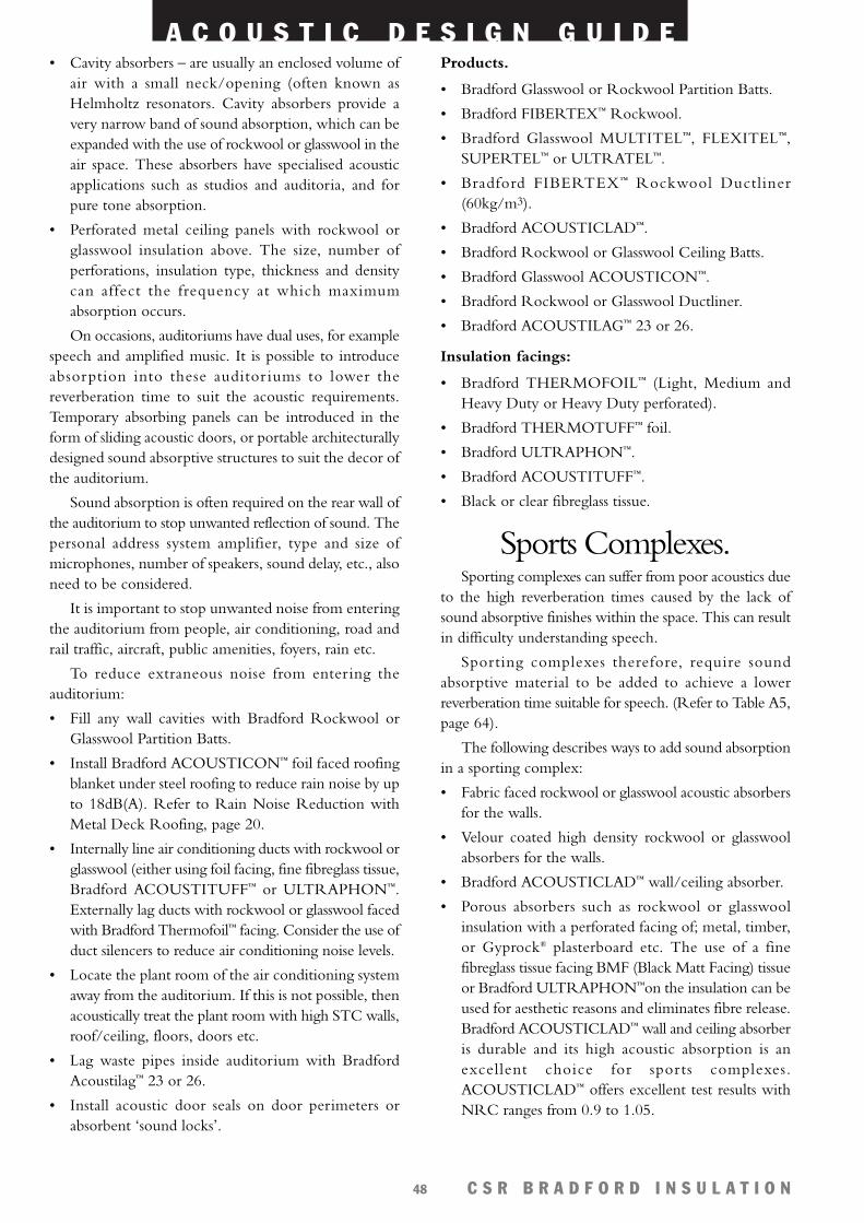
A C O U S T I C D E S I G N G U I D E
C S R B R A D F O R D I N S U L A T I O N48
• Cavity absorbers – are usually an enclosed volume ofair with a small neck/opening (often known asHelmholtz resonators. Cavity absorbers provide avery narrow band of sound absorption, which can beexpanded with the use of rockwool or glasswool in theair space. These absorbers have specialised acousticapplications such as studios and auditoria, and forpure tone absorption.
• Perforated metal ceiling panels with rockwool orglasswool insulation above. The size, number ofperforations, insulation type, thickness and densitycan affect the frequency at which maximumabsorption occurs.
On occasions, auditoriums have dual uses, for examplespeech and amplified music. It is possible to introduceabsorption into these auditor iums to lower thereverberation time to suit the acoustic requirements.Temporary absorbing panels can be introduced in theform of sliding acoustic doors, or portable architecturallydesigned sound absorptive structures to suit the decor ofthe auditorium.
Sound absorption is often required on the rear wall ofthe auditorium to stop unwanted reflection of sound. Thepersonal address system amplifier, type and size ofmicrophones, number of speakers, sound delay, etc., alsoneed to be considered.
It is important to stop unwanted noise from enteringthe auditorium from people, air conditioning, road andrail traffic, aircraft, public amenities, foyers, rain etc.
To reduce extraneous noise from entering theauditorium:
• Fill any wall cavities with Bradford Rockwool orGlasswool Partition Batts.
• Install Bradford ACOUSTICON™ foil faced roofingblanket under steel roofing to reduce rain noise by upto 18dB(A). Refer to Rain Noise Reduction withMetal Deck Roofing, page 20.
• Internally line air conditioning ducts with rockwool orglasswool (either using foil facing, fine fibreglass tissue,Bradford ACOUSTITUFF™ or ULTRAPHON™.Externally lag ducts with rockwool or glasswool facedwith Bradford Thermofoil™ facing. Consider the use ofduct silencers to reduce air conditioning noise levels.
• Locate the plant room of the air conditioning systemaway from the auditorium. If this is not possible, thenacoustically treat the plant room with high STC walls,roof/ceiling, floors, doors etc.
• Lag waste pipes inside auditorium with BradfordAcoustilag™ 23 or 26.
• Install acoustic door seals on door perimeters orabsorbent ‘sound locks’.
Products.
• Bradford Glasswool or Rockwool Partition Batts.
• Bradford FIBERTEX™ Rockwool.
• Bradford Glasswool MULTITEL™, FLEXITEL™,SUPERTEL™ or ULTRATEL™.
• Bradford FIBERTEX™ Rockwool Ductliner(60kg/m3).
• Bradford ACOUSTICLAD™.
• Bradford Rockwool or Glasswool Ceiling Batts.
• Bradford Glasswool ACOUSTICON™.
• Bradford Rockwool or Glasswool Ductliner.
• Bradford ACOUSTILAG™ 23 or 26.
Insulation facings:
• Bradford THERMOFOIL™ (Light, Medium andHeavy Duty or Heavy Duty perforated).
• Bradford THERMOTUFF™ foil.
• Bradford ULTRAPHON™.
• Bradford ACOUSTITUFF™.
• Black or clear fibreglass tissue.
Sports Complexes.Sporting complexes can suffer from poor acoustics due
to the high reverberation times caused by the lack ofsound absorptive finishes within the space. This can resultin difficulty understanding speech.
Sporting complexes therefore, require soundabsorptive material to be added to achieve a lowerreverberation time suitable for speech. (Refer to Table A5,page 64).
The following describes ways to add sound absorptionin a sporting complex:
• Fabric faced rockwool or glasswool acoustic absorbersfor the walls.
• Velour coated high density rockwool or glasswoolabsorbers for the walls.
• Bradford ACOUSTICLAD™ wall/ceiling absorber.
• Porous absorbers such as rockwool or glasswoolinsulation with a perforated facing of; metal, timber,or Gyprock® plasterboard etc. The use of a finefibreglass tissue facing BMF (Black Matt Facing) tissueor Bradford ULTRAPHON™on the insulation can beused for aesthetic reasons and eliminates fibre release.Bradford ACOUSTICLAD™ wall and ceiling absorberis durable and its high acoustic absorption is anexcellent choice for sports complexes.ACOUSTICLAD™ offers excellent test results withNRC ranges from 0.9 to 1.05.
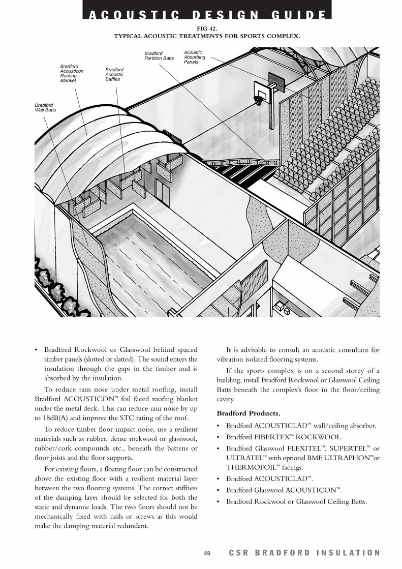
A C O U S T I C D E S I G N G U I D E
C S R B R A D F O R D I N S U L A T I O N49
• Bradford Rockwool or Glasswool behind spacedtimber panels (slotted or slatted). The sound enters theinsulation through the gaps in the timber and isabsorbed by the insulation.
To reduce rain nose under metal roofing, installBradford ACOUSTICON™ foil faced roofing blanketunder the metal deck. This can reduce rain noise by upto 18dB(A) and improve the STC rating of the roof.
To reduce timber floor impact noise, use a resilientmaterials such as rubber, dense rockwool or glasswool,rubber/cork compounds etc., beneath the battens orfloor joists and the floor supports.
For existing floors, a floating floor can be constructedabove the existing floor with a resilient material layerbetween the two flooring systems. The correct stiffnessof the damping layer should be selected for both thestatic and dynamic loads. The two floors should not bemechanically fixed with nails or screws as this wouldmake the damping material redundant.
It is advisable to consult an acoustic consultant forvibration isolated flooring systems.
If the sports complex is on a second storey of abuilding, install Bradford Rockwool or Glasswool CeilingBatts beneath the complex’s floor in the floor/ceilingcavity.
Bradford Products.
• Bradford ACOUSTICLAD™ wall/ceiling absorber.
• Bradford FIBERTEX™ ROCKWOOL.
• Bradford Glasswool FLEXITEL™, SUPERTEL™ orULTRATEL™ with optional BMF, ULTRAPHON™orTHERMOFOIL™ facings.
• Bradford ACOUSTICLAD™.
• Bradford Glasswool ACOUSTICON™.
• Bradford Rockwool or Glasswool Ceiling Batts.
FIG 42. TYPICAL ACOUSTIC TREATMENTS FOR SPORTS COMPLEX.
BradfordAcousticBaffles
BradfordWall Batts
BradfordAcousticonRoofingBlanket
BradfordPartition Batts
AcousticAbsorbingPanels
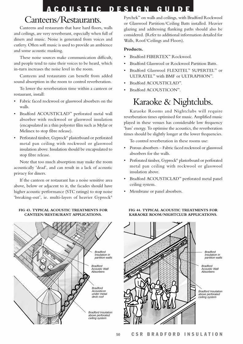
A C O U S T I C D E S I G N G U I D E
C S R B R A D F O R D I N S U L A T I O N50
Fyrchek™ on walls and ceilings, with Bradford Rockwoolor Glasswool Partition/Ceiling Batts installed. Heavierglazing and addressing flanking paths should also beconsidered. (Refer to additional information detailed forWalls, Roof/Ceilings and Floors).
Products.
• Bradford FIBERTEX™ Rockwool.
• Bradford Glasswool or Rockwool Partition Batts.
• Bradford Glasswool FLEXITEL™ SUPERTEL™ orULTRATEL™ with BMF or ULTRAPHON™.
• Bradford ACOUSTICLAD™.
• Bradford ACOUSTICON™.
Karaoke & Nightclubs.Karaoke Rooms and Nightclubs will require
reverberation times optimised for music. Amplified musicplayed in these venues has considerable low frequency‘bass’ energy. To optimise the acoustics, the reverberationtimes should be slightly longer at the lower frequencies.
To control reverberation in these rooms use:
• Porous absorbers – Fabric faced rockwool or glasswoolabsorbers for the walls.
• Perforated timber, Gyprock® plasterboard or perforatedmetal pan ceiling with rockwool or glasswoolinsulation above.
• Bradford ACOUSTICLAD™ perforated metal panelceiling system.
• Membrane or panel absorbers.
Canteens/Restaurants.Canteens and restaurants that have hard floors, walls
and ceilings, are very reverberant, especially when full ofdiners and music. Noise is generated from voices andcutlery. Often soft music is used to provide an ambienceand some acoustic masking.
These noise sources make communication difficult,and people tend to raise their voices to be heard, whichin-turn increases the noise level in the room.
Canteens and restaurants can benefit from addedsound absorption in the room to control reverberation.
To lower the reverberation time within a canteen orrestaurant, install:
• Fabric faced rockwool or glasswool absorbers on thewalls.
• Bradford ACOUSTICLAD™ perforated metal wallabsorber with rockwool or glasswool insulation(encapsulated in a thin polyester film such as Mylar orMelinex to stop fibre release).
• Perforated timber, Gyprock® plasterboard or perforatedmetal pan ceiling with rockwool or glasswoolinsulation above. Insulation should be encapsulated tostop fibre release.
Note that too much absorption may make the roomacoustically ‘dead’, and can result in a lack of acousticprivacy for diners.
If the canteen or restaurant has a noise sensitive areaabove, below or adjacent to it, the facades should havehigher acoustic performance (STC ratings) to stop noise‘breaking-out’, ie. multi-layers of heavier Gyprock®
FIG 43. TYPICAL ACOUSTIC TREATMENTS FORCANTEEN/RESTAURANT APPLICATIONS.
BradfordAcoustic WallAbsorbers
BradfordInsulation inpartition walls
Bradford Insulationabove perforatedceiling system
BradfordAcousticonunder metaldeck roof
FIG 44. TYPICAL ACOUSTIC TREATMENTS FORKARAOKE ROOM/NIGHTCLUB APPLICATIONS.
BradfordAcoustic WallAbsorbers
BradfordInsulation inpartition walls
Bradford Insulationabove perforatedceiling system
A C O U S T I C D E S I G N G U I D E
C S R B R A D F O R D I N S U L A T I O N51
Karaoke rooms and nightclubs can cause disturbancefor others nearby as music sound levels inside can reachor exceed 100dB(A). These rooms should be ‘soundproofed’ if they are likely to cause disturbance to others.To do this, building envelopes with very high STCratings are required.
The following acoustic treatments are recommended.
WALLS.Use multiple layers of CSR Gyprock Fyrchek™
plasterboard to add mass and increase the STC of thewalls. (The more mass that is used, the higher the STCrating). Ideally, the wall should have two separate studswith Bradford Rockwool or Glasswool Partition Battsinside the cavity of the walls for an increase of up to 10STC. If this is not possible, then staggered studs or thewidest possible stud cavity should be used (to reducelow frequency sound transmission) and filled withBradford Rockwool or Glasswool Partition Batts.
CEILING.Ceiling should have extra mass added to increase the
STC. Multi layers of CSR Gyprock® plasterboard can beused with Bradford Rockwool or Glasswool CeilingBatts above. Beneath the plasterboard ceiling, a suspendedperforated metal pan ceiling can be used to providesound absorption in the room.
WINDOWS.Windows should be double glazed with preferably
different size laminated glass panes (laminated glass hasbetter damping). Air gaps between the glass panes shouldbe properly sealed around the perimeter. Thickerlaminated single pane glass is the next best choice.
DOORS.Doors should be solid core timber or metal with
good quality acoustic door seals. An insulated ‘soundlock’ using acoustically treated doors will provide betteracoustic performance.
Note that for higher STC walls, ceilings and floors,flanking must be considered. (Refer to ‘Flanking Paths’,page 59).
Some Karaoke restaurants/clubs have many Karaokebooths which require acoustic isolation from each other.It is recommended that high STC rating walls are usedto acoustically isolate these rooms from each other. Referto the CSR Gyprock Fire & Acoustic Design Guide,NºGYP500 to choose a wall system.
Flanking paths should also be considered whenacoustically isolating rooms requiring high STC ratings.Sometimes these flanking paths can be the limiting factorin obtaining acoustic privacy from room to room.
It is advisable to engage the services of an acousticconsultant to design sound proofing for rooms with veryhigh noise levels, in particular, Karaoke rooms andnightclubs.
Products.
• Bradford Rockwool FIBERTEX™ 350, 450.
• Bradford Glasswool FLEXITEL™, SUPERTEL™,ULTRATEL™.
• Bradford Glasswool Absorption Blanket.
• Bradford Glasswool Ceiling Panel Overlays.
• Bradford Rockwool or Glasswool Partition Batts.
• Bradford ACOUSTICLAD™.
Shopping Centres.In shopping centres, the designers should look at
noise control in the following areas:
• Between shops to provide acoustic privacy – refer tosections in this book on wall and ceiling insulation.
• Reverberation control – within the shopping centreopen areas (ie. stage and dining areas).
• Rain noise under steel roofing – install BradfordAcousticon™ hard under steel deck roofing.
• Air conditioning and mechanical services noise –acoustically treat plant room, internally line andexternally lag air conditioning and air extraction ducts,particularly where they are exposed. Plant rooms shoulduse high STC rating walls, ceilings and floors if next tonoise sensitive areas. Plant room walls should be linedwith Bradford Acousticlad™ to absorb noise.
• Carpark noise – avoid steel speed humps which worklose with time and become noisy.
Products.
• Bradford Rockwool or Glasswool Partition Batts.
• Bradford FIBERTEX™ Rockwool.
• Bradford Glasswool SUPERTEL™, ULTRATEL™.
• Bradford ACOUSTICON™.
• Bradford ACOUSTICLAD™.
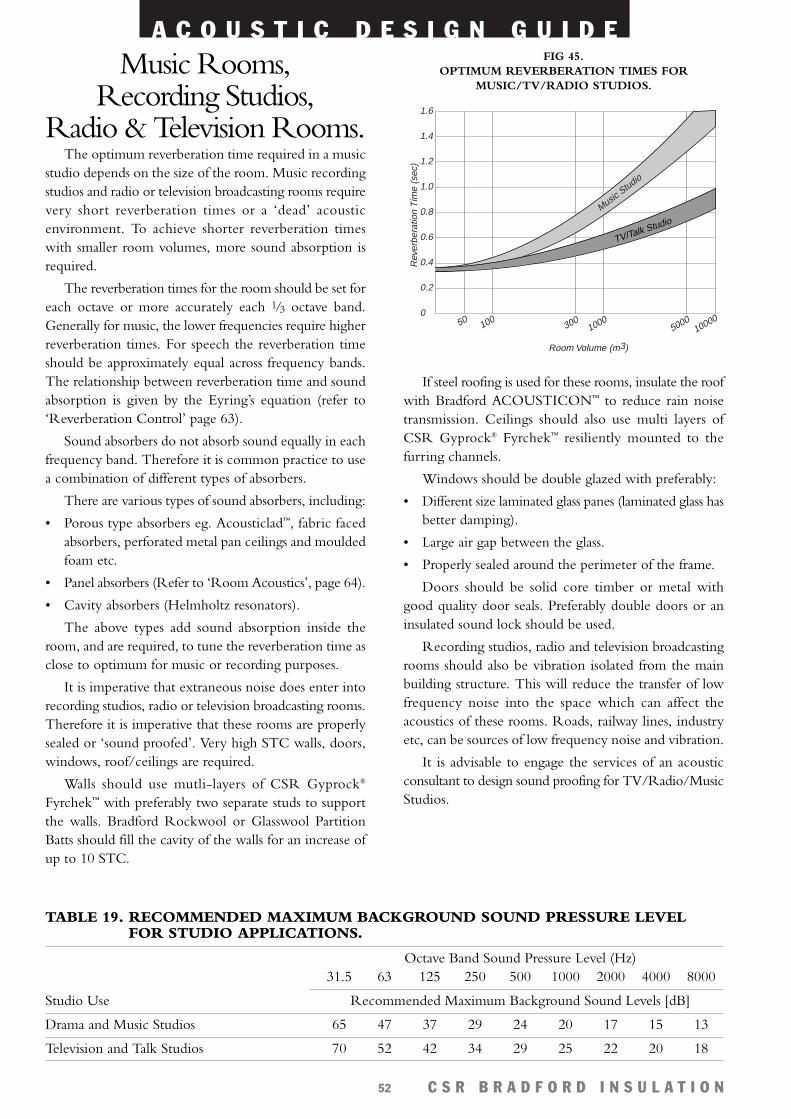
A C O U S T I C D E S I G N G U I D E
C S R B R A D F O R D I N S U L A T I O N52
Music Rooms,Recording Studios,
Radio & Television Rooms.The optimum reverberation time required in a music
studio depends on the size of the room. Music recordingstudios and radio or television broadcasting rooms requirevery short reverberation times or a ‘dead’ acousticenvironment. To achieve shorter reverberation timeswith smaller room volumes, more sound absorption isrequired.
The reverberation times for the room should be set foreach octave or more accurately each 1/3 octave band.Generally for music, the lower frequencies require higherreverberation times. For speech the reverberation timeshould be approximately equal across frequency bands.The relationship between reverberation time and soundabsorption is given by the Eyring’s equation (refer to‘Reverberation Control’ page 63).
Sound absorbers do not absorb sound equally in eachfrequency band. Therefore it is common practice to usea combination of different types of absorbers.
There are various types of sound absorbers, including:
• Porous type absorbers eg. Acousticlad™, fabric facedabsorbers, perforated metal pan ceilings and mouldedfoam etc.
• Panel absorbers (Refer to ‘Room Acoustics’, page 64).
• Cavity absorbers (Helmholtz resonators).
The above types add sound absorption inside theroom, and are required, to tune the reverberation time asclose to optimum for music or recording purposes.
It is imperative that extraneous noise does enter intorecording studios, radio or television broadcasting rooms.Therefore it is imperative that these rooms are properlysealed or ‘sound proofed’. Very high STC walls, doors,windows, roof/ceilings are required.
Walls should use mutli-layers of CSR Gyprock®
Fyrchek™ with preferably two separate studs to supportthe walls. Bradford Rockwool or Glasswool PartitionBatts should fill the cavity of the walls for an increase ofup to 10 STC.
If steel roofing is used for these rooms, insulate the roofwith Bradford ACOUSTICON™ to reduce rain noisetransmission. Ceilings should also use multi layers ofCSR Gyprock® Fyrchek™ resiliently mounted to thefurring channels.
Windows should be double glazed with preferably:
• Different size laminated glass panes (laminated glass hasbetter damping).
• Large air gap between the glass.
• Properly sealed around the perimeter of the frame.
Doors should be solid core timber or metal withgood quality door seals. Preferably double doors or aninsulated sound lock should be used.
Recording studios, radio and television broadcastingrooms should also be vibration isolated from the mainbuilding structure. This will reduce the transfer of lowfrequency noise into the space which can affect theacoustics of these rooms. Roads, railway lines, industryetc, can be sources of low frequency noise and vibration.
It is advisable to engage the services of an acousticconsultant to design sound proofing for TV/Radio/MusicStudios.
FIG 45. OPTIMUM REVERBERATION TIMES FOR
MUSIC/TV/RADIO STUDIOS.
Rev
erbe
ratio
n T
ime
(sec
)
Room Volume (m3)
1.0
0
0.2
0.4
0.6
0.8
1.2
1.4
1.6
50 100300
10005000
10000
Music Studio
TV/Talk Studio
TABLE 19. RECOMMENDED MAXIMUM BACKGROUND SOUND PRESSURE LEVELFOR STUDIO APPLICATIONS.
Octave Band Sound Pressure Level (Hz)31.5 63 125 250 500 1000 2000 4000 8000
Studio Use Recommended Maximum Background Sound Levels [dB]
Drama and Music Studios 65 47 37 29 24 20 17 15 13
Television and Talk Studios 70 52 42 34 29 25 22 20 18

A C O U S T I C D E S I G N G U I D E
C S R B R A D F O R D I N S U L A T I O N53
Products.
• Bradford FIBERTEX™ Rockwool.
• Bradford Glasswool SUPERTEL™ or ULTRATEL™.
• Bradford ACOUSTILAG™.
• Heavy duty perforated THERMOFOIL™.
OEM.CSR Bradford Insulation supplies the full range of
glasswool and rockwool products to original equipmentmanufacturers (OEMs).
Bradford insulation is used for acoustic or thermalpurposes, and adds value to OEMs’ products. Glasswoolcan be used for the following requirements:
• Thermal.
• Acoustic.
• Fire resistance.
CSR Bradford Insulation supplies many OEMs, andeach has unique requirements for rockwool and glasswoolinsulation products.
OEMs should contact the CSR Bradford InsulationOffice in their reg ion to discuss their specificrequirements.
Products.
• Bradford Rockwool.
• Bradford Glasswool.
References.1 Sound Research Laboratories, Noise Control in Building
Services, Pergamon Press, First Edition 1988.
2 Bruel & Kjaer, Noise Control, Principles & Practice,Naerum Offset, Second Edition, 1986.
3 D.A Bies & Hansen, Engineering Noise Control, E& FN Spon, Second Edition, 1996.
4 L.L Beranek, Noise And Vibration Control, Instituteof Noise Control, Revised Edition, 1988.
Products.
• Bradford Glasswool FLEXITEL™, SUPERTEL™,ULTRATEL™.
• Bradford FIBERTEX™ Rockwool.
• Bradford ACOUSTICLAD™.
Heavy Plant.Engine compartments of plant and machinery should
be lined with Bradford Rockwool or Glasswool facedwith Bradford Heavy Duty 750P THERMOFOIL™
Perforated to absorb engine and ancillary noise. As enginenoise has most energy at low frequencies, insulationthickness should be at least 75mm. The thicker theinsulation, the better the low frequency sound absorption.
Lightweight sheet steel casings can often vibrate andemit noise. To damp these casings, BradfordACOUSTILAG™ can be used. The glasswool side of theAcoustilag should be secured firmly to the outside of thesheet steel to increase the panel’s mass. The mass of theloaded vinyl, damps the vibrating panel, and reduces noise.
Operators cabins should also be fully enclosed and wellsealed to stop noise from entering. Dust inside an operatorcabin is a good indication the cabin is poorly sealed.Cabins should also be vibration isolated for operatorcomfort and safety, and also to minimise re-radiated noisefrom lightweight materials. The cabin can be lined withrockwool or glasswool insulation with a suitable facingsuch as perforated THERMOFOIL™ to absorb noisewithin the cabin.
FIG 46. TYPICAL ACOUSTIC TREATMENTS FORTV/RADIO/MUSIC STUDIO APPLICATIONS.
Bradford Insulationin high STC partitionwalls
Bradford AcousticAbsorbers to controlreverberation
Bradford Insulationtreatment to airconditioning ducts
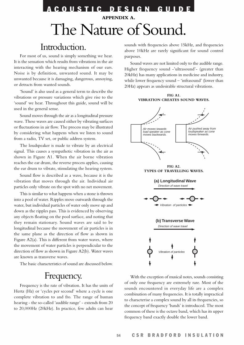
A C O U S T I C D E S I G N G U I D E
C S R B R A D F O R D I N S U L A T I O N54
Introduction.For most of us, sound is simply something we hear.
It is the sensation which results from vibrations in the airinteracting with the hearing mechanism of our ears.Noise is by definition, unwanted sound. It may beunwanted because it is damaging, dangerous, annoying,or detracts from wanted sounds.
‘Sound’ is also used as a general term to describe thevibrations or pressure variations which give rise to the‘sound’ we hear. Throughout this guide, sound will beused in the general sense.
Sound moves through the air as a longitudinal pressurewave. These waves are caused either by vibrating surfacesor fluctuations in air flow. The process may be illustratedby considering what happens when we listen to soundfrom a radio, TV set, or public address system.
The loudspeaker is made to vibrate by an electricalsignal. This causes a sympathetic vibration in the air asshown in Figure A1. When the air borne vibrationreaches the ear drum, the reverse process applies, causingthe ear drum to vibrate, stimulating the hearing system.
Sound flow is described as a wave, because it is thevibration that moves through the air. Individual airparticles only vibrate on the spot with no net movement.
This is similar to what happens when a stone is throwninto a pool of water. Ripples move outwards through thewater, but individual particles of water only move up anddown as the ripples pass. This is evidenced by observingany objects floating on the pool surface, and noting thatthey remain stationary. Sound waves are said to belongitudinal because the movement of air particles is inthe same plane as the direction of flow as shown inFigure A2(a). This is different from water waves, wherethe movement of water particles is perpendicular to thedirection of flow as shown in Figure A2(b). Water wavesare known as transverse waves.
The basic characteristics of sound are discussed below.
Frequency.Frequency is the rate of vibration. It has the units of
Hertz (Hz) or ‘cycles per second’ where a cycle is onecomplete vibration to and fro. The range of humanhearing - the so-called ‘audible range’ - extends from 20to 20,000Hz (20kHz). In practice, few adults can hear
sounds with frequencies above 15kHz, and frequenciesabove 10kHz are rarely significant for sound controlpurposes.
Sound waves are not limited only to the audible range.Higher frequency sound -’ultrasound’- (greater than20kHz) has many applications in medicine and industry,while lower frequency sound – ‘infrasound’ (lower than20Hz) appears as undesirable structural vibrations.
With the exception of musical notes, sounds consistingof only one frequency are extremely rare. Most of thesounds encountered in everyday life are a complexcombination of many frequencies. It is totally impracticalto characterise a complex sound by all its frequencies, sothe concept of frequency ‘bands’ is introduced. The mostcommon of these is the octave band, which has its upperfrequency band exactly double the lower band.
Direction of wave travel
Direction of wave travel
Vibration of particles
Vibration of particles
(a) Longitudinal Wave
(b) Transverse Wave
FIG A2. TYPES OF TRAVELLING WAVES.
Air moves towards load speaker as cone moves backwards.
Air pushed away from loudspeaker as cone moves forwards.
FIG A1. VIBRATION CREATES SOUND WAVES.
The Nature of Sound.APPENDIX A.
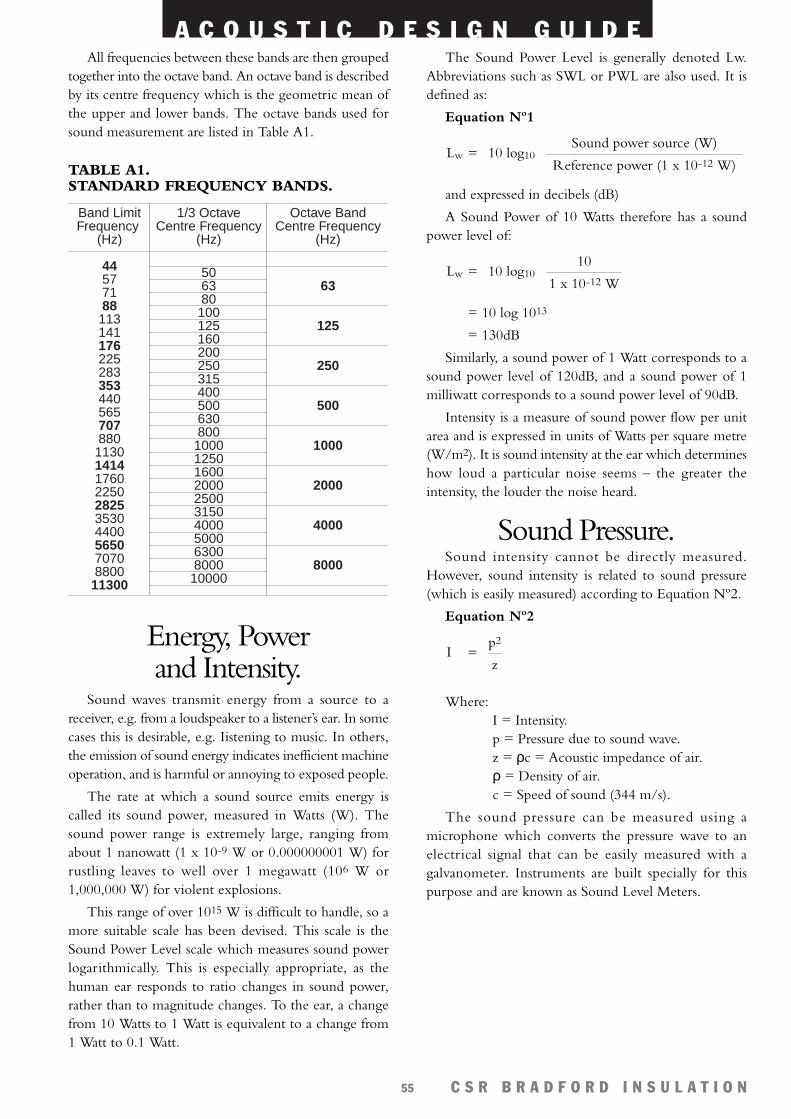
A C O U S T I C D E S I G N G U I D E
C S R B R A D F O R D I N S U L A T I O N55
All frequencies between these bands are then groupedtogether into the octave band. An octave band is describedby its centre frequency which is the geometric mean ofthe upper and lower bands. The octave bands used forsound measurement are listed in Table A1.
TABLE A1. STANDARD FREQUENCY BANDS.
Energy, Powerand Intensity.
Sound waves transmit energy from a source to areceiver, e.g. from a loudspeaker to a listener’s ear. In somecases this is desirable, e.g. Iistening to music. In others,the emission of sound energy indicates inefficient machineoperation, and is harmful or annoying to exposed people.
The rate at which a sound source emits energy iscalled its sound power, measured in Watts (W). Thesound power range is extremely large, ranging fromabout 1 nanowatt (1 x 10⁻⁹ W or 0.000000001 W) forrustling leaves to well over 1 megawatt (106 W or1,000,000 W) for violent explosions.
This range of over 1015 W is difficult to handle, so amore suitable scale has been devised. This scale is theSound Power Level scale which measures sound powerlogarithmically. This is especially appropriate, as thehuman ear responds to ratio changes in sound power,rather than to magnitude changes. To the ear, a changefrom 10 Watts to 1 Watt is equivalent to a change from1 Watt to 0.1 Watt.
The Sound Power Level is generally denoted Lw.Abbreviations such as SWL or PWL are also used. It isdefined as:
Equation Nº1
=
and expressed in decibels (dB)
A Sound Power of 10 Watts therefore has a soundpower level of:
=
= 10 log 1013
= 130dB
Similarly, a sound power of 1 Watt corresponds to asound power level of 120dB, and a sound power of 1milliwatt corresponds to a sound power level of 90dB.
Intensity is a measure of sound power flow per unitarea and is expressed in units of Watts per square metre(W/m2). It is sound intensity at the ear which determineshow loud a particular noise seems – the greater theintensity, the louder the noise heard.
Sound Pressure.Sound intensity cannot be directly measured.
However, sound intensity is related to sound pressure(which is easily measured) according to Equation Nº2.
Equation Nº2
Where: I = Intensity.p = Pressure due to sound wave.z = ρc = Acoustic impedance of air. ρ = Density of air.c = Speed of sound (344 m/s).
The sound pressure can be measured using amicrophone which converts the pressure wave to anelectrical signal that can be easily measured with agalvanometer. Instruments are built specially for thispurpose and are known as Sound Level Meters.
p2
zI =
10
1 x 10-12 W10 log10Lw
Sound power source (W)
Reference power (1 x 10-12 W)10 log10Lw
Band Limit Frequency
(Hz)
44577188113141176225283353440565707880113014141760225028253530440056507070880011300
1/3 OctaveCentre Frequency
(Hz)
506380100125160200250315400500630800100012501600200025003150400050006300800010000
Octave BandCentre Frequency
(Hz)
63
125
250
500
1000
2000
4000
8000
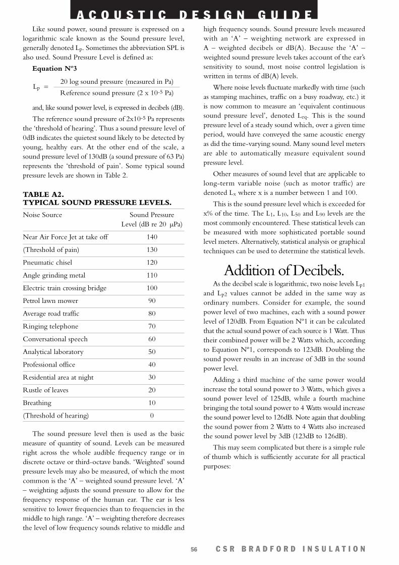
A C O U S T I C D E S I G N G U I D E
C S R B R A D F O R D I N S U L A T I O N56
Like sound power, sound pressure is expressed on alogarithmic scale known as the Sound pressure level,generally denoted Lp. Sometimes the abbreviation SPL isalso used. Sound Pressure Level is defined as:
Equation Nº3
and, like sound power level, is expressed in decibels (dB).
The reference sound pressure of 2x10⁻⁵ Pa representsthe ‘threshold of hearing’. Thus a sound pressure level of0dB indicates the quietest sound likely to be detected byyoung, healthy ears. At the other end of the scale, asound pressure level of 130dB (a sound pressure of 63 Pa)represents the ‘threshold of pain’. Some typical soundpressure levels are shown in Table 2.
TABLE A2. TYPICAL SOUND PRESSURE LEVELS.
Noise Source Sound PressureLevel (dB re 20 µPa)
Near Air Force Jet at take off 140
(Threshold of pain) 130
Pneumatic chisel 120
Angle grinding metal 110
Electric train crossing bridge 100
Petrol lawn mower 90
Average road traffic 80
Ringing telephone 70
Conversational speech 60
Analytical laboratory 50
Professional office 40
Residential area at night 30
Rustle of leaves 20
Breathing 10
(Threshold of hearing) 0
The sound pressure level then is used as the basicmeasure of quantity of sound. Levels can be measuredright across the whole audible frequency range or indiscrete octave or third-octave bands. ‘Weighted’ soundpressure levels may also be measured, of which the mostcommon is the ‘A’ – weighted sound pressure level. ‘A’– weighting adjusts the sound pressure to allow for thefrequency response of the human ear. The ear is lesssensitive to lower frequencies than to frequencies in themiddle to high range. ‘A’ – weighting therefore decreasesthe level of low frequency sounds relative to middle and
20 log sound pressure (measured in Pa)
Reference sound pressure (2 x 10⁻⁵ Pa)Lp =
high frequency sounds. Sound pressure levels measuredwith an ‘A’ – weighting network are expressed inA – weighted decibels or dB(A). Because the ‘A’ –weighted sound pressure levels takes account of the ear’ssensitivity to sound, most noise control legislation iswritten in terms of dB(A) levels.
Where noise levels fluctuate markedly with time (suchas stamping machines, traffic on a busy roadway, etc.) itis now common to measure an ‘equivalent continuoussound pressure level’, denoted Leq. This is the soundpressure level of a steady sound which, over a given timeperiod, would have conveyed the same acoustic energyas did the time-varying sound. Many sound level metersare able to automatically measure equivalent soundpressure level.
Other measures of sound level that are applicable tolong-term variable noise (such as motor traffic) aredenoted Lx where x is a number between 1 and 100.
This is the sound pressure level which is exceeded forx% of the time. The L1, L10, L50 and L90 levels are themost commonly encountered. These statistical levels canbe measured with more sophisticated portable soundlevel meters. Alternatively, statistical analysis or graphicaltechniques can be used to determine the statistical levels.
Addition of Decibels.As the decibel scale is logarithmic, two noise levels Lp1
and Lp2 values cannot be added in the same way asordinary numbers. Consider for example, the soundpower level of two machines, each with a sound powerlevel of 120dB. From Equation Nº1 it can be calculatedthat the actual sound power of each source is 1 Watt. Thustheir combined power will be 2 Watts which, accordingto Equation Nº1, corresponds to 123dB. Doubling thesound power results in an increase of 3dB in the soundpower level.
Adding a third machine of the same power wouldincrease the total sound power to 3 Watts, which gives asound power level of 125dB, while a fourth machinebringing the total sound power to 4 Watts would increasethe sound power level to 126dB. Note again that doublingthe sound power from 2 Watts to 4 Watts also increasedthe sound power level by 3dB (123dB to 126dB).
This may seem complicated but there is a simple ruleof thumb which is sufficiently accurate for all practicalpurposes:
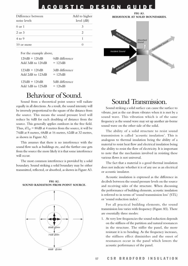
A C O U S T I C D E S I G N G U I D E
C S R B R A D F O R D I N S U L A T I O N57
Difference between Add to highernoise levels level (dB)
0 or 1 3
2 or 3 2
4 to 9 1
10 or more 0
For the example above,
120dB + 120dB 0dB differenceAdd 3dB to 120dB = 123dB
123dB + 120dB 3dB differenceAdd 2dB to 123dB = 125dB
125dB + 120dB 5dB differenceAdd 1dB to 125dB = 126dB
Behaviour of Sound.Sound from a theoretical point source will radiate
equally in all directions. As a result, the sound intensity willbe inversely proportional to the square of the distance fromthe source. This means the sound pressure level willreduce by 6dB for each doubling of distance from thesource. This generally applies outdoors in the free field.Thus, if Lp = 80dB at 4 metres from the source, it will be74dB at 8 metres, 68dB at 16 metres, 62dB at 32 metres,as shown in Figure A2.
This assumes that there is no interference with thesound flow such as buildings etc, and the further one getsfrom the source the more likely it is that some interferencewill occur.
The most common interference is provided by a solidboundary. Sound striking a solid boundary may be eithertransmitted, reflected, or absorbed, as shown in Figure A3.
Sound Transmission.Sound striking a solid surface can cause the surface to
vibrate, just as the ear drum vibrates when it is met by asound wave. This vibration which is of the samefrequency as the sound wave may set up another air-bornesound wave on the other side of the solid.
The ability of a solid structure to resist soundtransmission is called ‘acoustic insulation’. This isanalogous to thermal insulation being the ability of amaterial to resist heat flow and electrical insulation beingthe ability to resist the flow of electricity. It is importantto note that the mechanism involved in resisting thesevarious flows is not universal.
The fact that a material is a good thermal insulationdoes not indicate whether it is of any use as an electricalor acoustic insulator.
Acoustic insulation is expressed as the difference indecibels between the sound pressure levels on the sourceand receiving sides of the structure. When discussingthe performance of building elements, acoustic insulationis referred to in terms of ‘sound transmission loss’ (STL)or ‘sound reduction index’.
For all practical building elements, the soundtransmission loss varies with frequency (Figure A5). Thereare essentially three modes:
1. At very low frequencies the sound reduction dependson the stiffness of the partition and natural resonancesin the structure. The stiffer the panel, the moreresistant it is to bending. As the frequency increases,the stiffness effect diminishes and the onset ofresonances occur in the panel which lowers theacoustic performance of the panel.
80dB @4m
74dB @8m
68dB @16m
FIG A2. SOUND RADIATION FROM POINT SOURCE.
Reflected Sound
Transmitted Sound
Reflected Sound
Transmitted Sound
AbsorbedSound
Incident Sound
FIG A3. BEHAVIOUR AT SOLID BOUNDARIES.
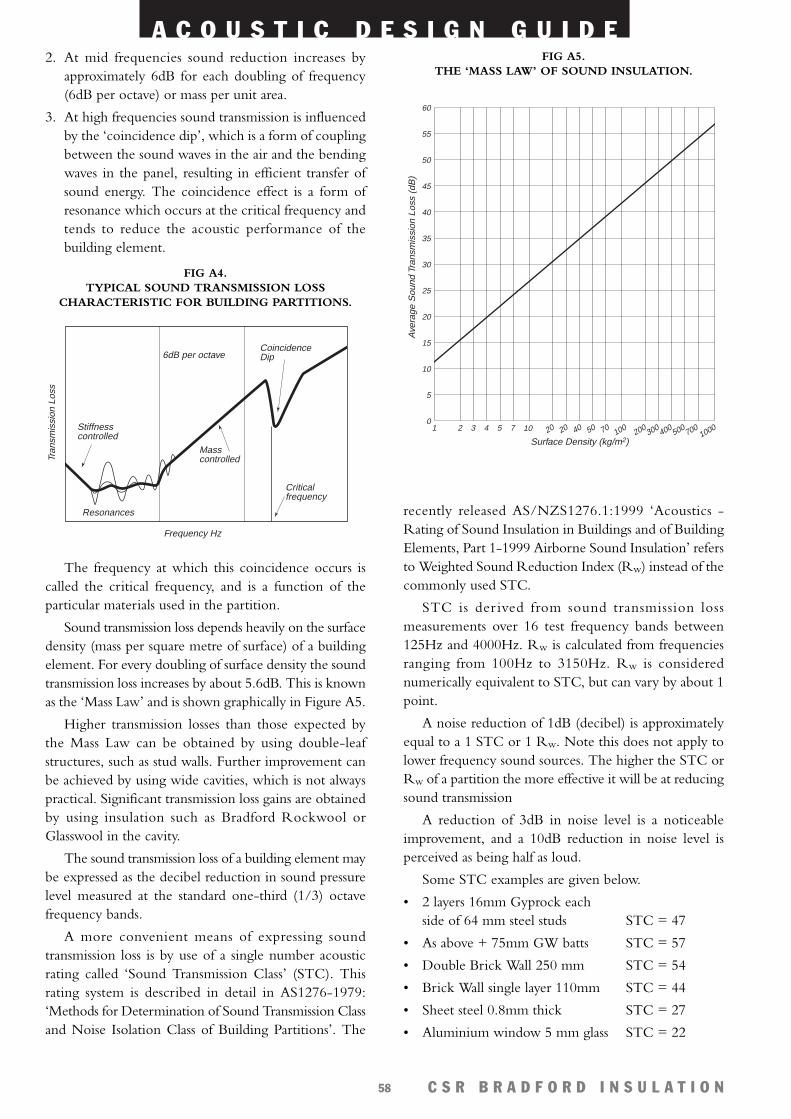
A C O U S T I C D E S I G N G U I D E
C S R B R A D F O R D I N S U L A T I O N58
2. At mid frequencies sound reduction increases byapproximately 6dB for each doubling of frequency(6dB per octave) or mass per unit area.
3. At high frequencies sound transmission is influencedby the ‘coincidence dip’, which is a form of couplingbetween the sound waves in the air and the bendingwaves in the panel, resulting in efficient transfer ofsound energy. The coincidence effect is a form ofresonance which occurs at the critical frequency andtends to reduce the acoustic performance of thebuilding element.
The frequency at which this coincidence occurs iscalled the critical frequency, and is a function of theparticular materials used in the partition.
Sound transmission loss depends heavily on the surfacedensity (mass per square metre of surface) of a buildingelement. For every doubling of surface density the soundtransmission loss increases by about 5.6dB. This is knownas the ‘Mass Law’ and is shown graphically in Figure A5.
Higher transmission losses than those expected bythe Mass Law can be obtained by using double-leafstructures, such as stud walls. Further improvement canbe achieved by using wide cavities, which is not alwayspractical. Significant transmission loss gains are obtainedby using insulation such as Bradford Rockwool orGlasswool in the cavity.
The sound transmission loss of a building element maybe expressed as the decibel reduction in sound pressurelevel measured at the standard one-third (1/3) octavefrequency bands.
A more convenient means of expressing soundtransmission loss is by use of a single number acousticrating called ‘Sound Transmission Class’ (STC). Thisrating system is described in detail in AS1276-1979:‘Methods for Determination of Sound Transmission Classand Noise Isolation Class of Building Partitions’. The
recently released AS/NZS1276.1:1999 ‘Acoustics -Rating of Sound Insulation in Buildings and of BuildingElements, Part 1-1999 Airborne Sound Insulation’ refersto Weighted Sound Reduction Index (Rw) instead of thecommonly used STC.
STC is der ived from sound transmission lossmeasurements over 16 test frequency bands between125Hz and 4000Hz. Rw is calculated from frequenciesranging from 100Hz to 3150Hz. Rw is considerednumerically equivalent to STC, but can vary by about 1point.
A noise reduction of 1dB (decibel) is approximatelyequal to a 1 STC or 1 Rw. Note this does not apply tolower frequency sound sources. The higher the STC orRw of a partition the more effective it will be at reducingsound transmission
A reduction of 3dB in noise level is a noticeableimprovement, and a 10dB reduction in noise level isperceived as being half as loud.
Some STC examples are given below.
• 2 layers 16mm Gyprock eachside of 64 mm steel studs STC = 47
• As above + 75mm GW batts STC = 57
• Double Brick Wall 250 mm STC = 54
• Brick Wall single layer 110mm STC = 44
• Sheet steel 0.8mm thick STC = 27
• Aluminium window 5 mm glass STC = 22
Ave
rage
Sou
nd T
rans
mis
sion
Los
s (d
B)
Surface Density (kg/m2)
1 2 3 4 5 7 10 20 20 40 50 70 100 200 300 400 500 7001000
0
5
10
15
20
25
30
35
40
45
50
55
60
FIG A5. THE ‘MASS LAW’ OF SOUND INSULATION.
Frequency Hz
Tran
smis
sion
Los
s
Stiffnesscontrolled
6dB per octave
Mass controlled
CoincidenceDip
Criticalfrequency
Resonances
FIG A4. TYPICAL SOUND TRANSMISSION LOSS
CHARACTERISTIC FOR BUILDING PARTITIONS.
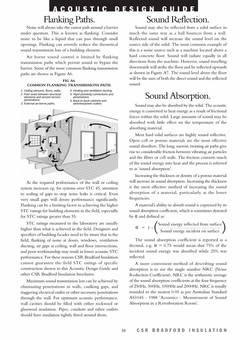
A C O U S T I C D E S I G N G U I D E
C S R B R A D F O R D I N S U L A T I O N59
Flanking Paths.Noise will always take the easiest path around a barrier
under question. This is known as flanking. Considernoise to be like a liquid that can pass through smallopenings. Flanking can severely reduce the theoreticalsound transmission loss of a building element.
Air borne sound control is limited by flankingtransmission paths which permit sound to bypass thebarrier. Some of the more common flanking transmissionpaths are shown in Figure A6.
As the required performance of the wall or ceilingsystem increases eg. for systems over STC 45, attentionto sealing of gaps to stop noise leaks is critical. Evenvery small gaps will derate performance significantly.Flanking can be a limiting factor in achieving the higherSTC ratings for building elements in the field, especiallyfor STC ratings greater than 55.
STC ratings measured in the laboratory are usuallyhigher than what is achieved in the field. Designers andspecifiers of building facades need to be aware that in thefield, flanking of noise at doors, windows, ventilationducting, air gaps at ceiling, wall and floor intersections,and poor workmanship may result in lower acoustic STCperformance. For these reasons CSR Bradford Insulationcannot guarantee the field STC ratings of specificconstruction shown in this Acoustic Design Guide andother CSR Bradford Insulation brochures.
Maximum sound transmission loss can be achieved byeliminating penetrations in walls, caulking gaps, andstaggering electrical outlet or other necessary penetrationsthrough the wall. For optimum acoustic performance,wall cavities should be filled with either rockwool orglasswool insulation. Pipes, conduits and other outletsshould have insulation tightly fitted around them.
Sound Reflection.Sound may also be reflected from a solid surface in
much the same way as a ball bounces from a wall.Reflected sound will increase the sound level on thesource side of the solid. The most common example ofthis is a noise source such as a machine located above ahard concrete floor. Sound will radiate equally in alldirections from the machine. However, sound travellingdownwards will strike the floor and be reflected upwardsas shown in Figure A7. The sound level above the floorwill be the sum of both the direct sound and the reflectedsound.
Sound Absorption.Sound may also be absorbed by the solid. The acoustic
energy is converted to heat energy as a result of frictionalforces within the solid. Large amounts of sound may beabsorbed with little effect on the temperature of theabsorbing material.
Most hard solid surfaces are highly sound reflective.Open cell or porous materials are the most effectivesound absorbers. The long, narrow, twisting air paths giverise to considerable friction between vibrating air particlesand the fibres or cell walls. The friction converts muchof the sound energy into heat and the process is referredto as ‘sound absorption’.
Increasing the thickness or density of a porous materialwill increase its sound absorption. Increasing the thicknessis the most effective method of increasing the soundabsorption of a material, particularly at the lowerfrequencies.
A material’s ability to absorb sound is expressed by itssound absorption coefficient, which is sometimes denotedby α and defined as:
1 –( )The sound absorption coefficient is reported as a
decimal, e.g. α = 0.75 would mean that 75% of theincident sound energy was absorbed while 25% wasreflected.
A more convenient method of describing soundabsorption is to use the single number NRC (NoiseReduction Coefficient). NRC is the arithmetic averageof the sound absorption coefficients at the four frequencyof 250Hz, 500Hz, 1000Hz and 2000Hz. NRC is usuallyrounded to the nearest 0.05 as per Australian StandardAS1045 : 1988 ‘Acoustics - Measurement of SoundAbsorption in a Reverberation Room’.
Sound energy reflected from surface
Sound energy incident on surfaceα =
FIG A6. COMMON FLANKING TRANSMISSIONS PATH.
1. Ceiling plenums, floors, walls.2. Poor seals between structural
elements and around servicepenetrations.
3. External air-borne paths.
4. Heating and ventilation ducting.5. Rigid plumbing connections and
penetrations.6. Back-to-back cabinets and
switches/power outlets.
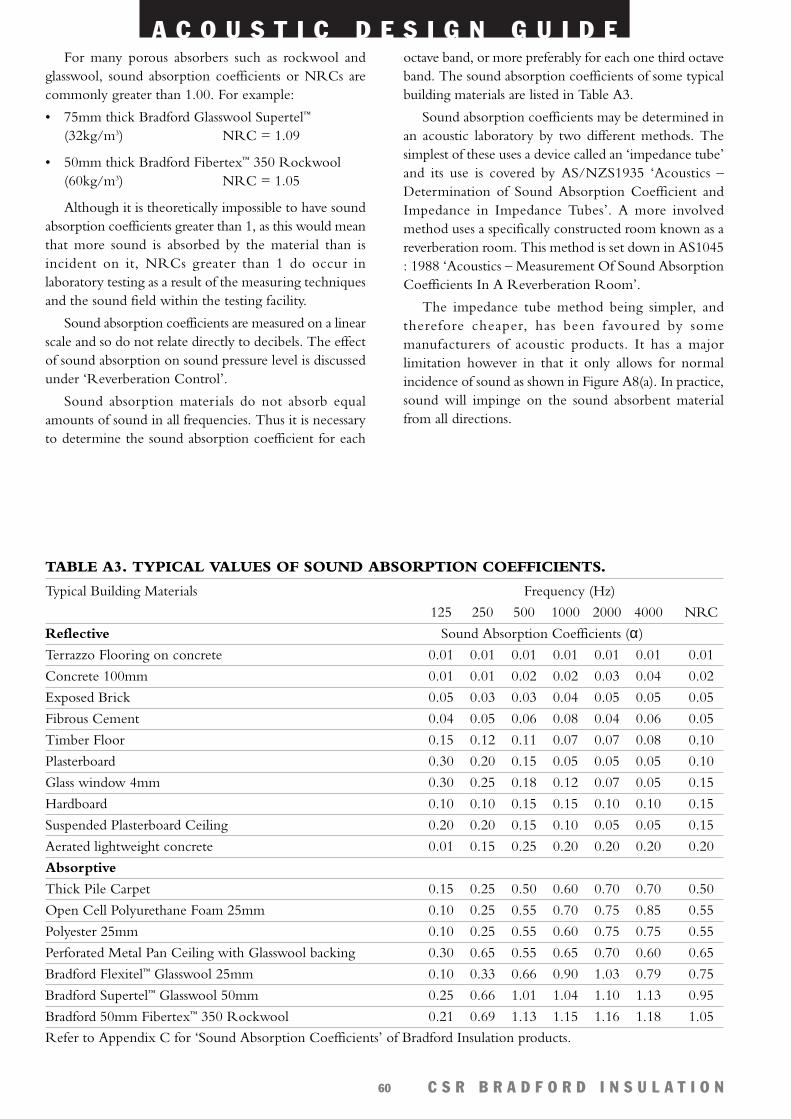
A C O U S T I C D E S I G N G U I D E
C S R B R A D F O R D I N S U L A T I O N60
For many porous absorbers such as rockwool andglasswool, sound absorption coefficients or NRCs arecommonly greater than 1.00. For example:
• 75mm thick Bradford Glasswool Supertel™
(32kg/m3) NRC = 1.09
• 50mm thick Bradford Fibertex™ 350 Rockwool(60kg/m3) NRC = 1.05
Although it is theoretically impossible to have soundabsorption coefficients greater than 1, as this would meanthat more sound is absorbed by the material than isincident on it, NRCs greater than 1 do occur inlaboratory testing as a result of the measuring techniquesand the sound field within the testing facility.
Sound absorption coefficients are measured on a linearscale and so do not relate directly to decibels. The effectof sound absorption on sound pressure level is discussedunder ‘Reverberation Control’.
Sound absorption materials do not absorb equalamounts of sound in all frequencies. Thus it is necessaryto determine the sound absorption coefficient for each
octave band, or more preferably for each one third octaveband. The sound absorption coefficients of some typicalbuilding materials are listed in Table A3.
Sound absorption coefficients may be determined inan acoustic laboratory by two different methods. Thesimplest of these uses a device called an ‘impedance tube’and its use is covered by AS/NZS1935 ‘Acoustics –Determination of Sound Absorption Coefficient andImpedance in Impedance Tubes’. A more involvedmethod uses a specifically constructed room known as areverberation room. This method is set down in AS1045: 1988 ‘Acoustics – Measurement Of Sound AbsorptionCoefficients In A Reverberation Room’.
The impedance tube method being simpler, andtherefore cheaper, has been favoured by somemanufacturers of acoustic products. It has a majorlimitation however in that it only allows for normalincidence of sound as shown in Figure A8(a). In practice,sound will impinge on the sound absorbent materialfrom all directions.
TABLE A3. TYPICAL VALUES OF SOUND ABSORPTION COEFFICIENTS.
Typical Building Materials Frequency (Hz)
125 250 500 1000 2000 4000 NRC
Reflective Sound Absorption Coefficients (α)
Terrazzo Flooring on concrete 0.01 0.01 0.01 0.01 0.01 0.01 0.01
Concrete 100mm 0.01 0.01 0.02 0.02 0.03 0.04 0.02
Exposed Brick 0.05 0.03 0.03 0.04 0.05 0.05 0.05
Fibrous Cement 0.04 0.05 0.06 0.08 0.04 0.06 0.05
Timber Floor 0.15 0.12 0.11 0.07 0.07 0.08 0.10
Plasterboard 0.30 0.20 0.15 0.05 0.05 0.05 0.10
Glass window 4mm 0.30 0.25 0.18 0.12 0.07 0.05 0.15
Hardboard 0.10 0.10 0.15 0.15 0.10 0.10 0.15
Suspended Plasterboard Ceiling 0.20 0.20 0.15 0.10 0.05 0.05 0.15
Aerated lightweight concrete 0.01 0.15 0.25 0.20 0.20 0.20 0.20
Absorptive
Thick Pile Carpet 0.15 0.25 0.50 0.60 0.70 0.70 0.50
Open Cell Polyurethane Foam 25mm 0.10 0.25 0.55 0.70 0.75 0.85 0.55
Polyester 25mm 0.10 0.25 0.55 0.60 0.75 0.75 0.55
Perforated Metal Pan Ceiling with Glasswool backing 0.30 0.65 0.55 0.65 0.70 0.60 0.65
Bradford Flexitel™ Glasswool 25mm 0.10 0.33 0.66 0.90 1.03 0.79 0.75
Bradford Supertel™ Glasswool 50mm 0.25 0.66 1.01 1.04 1.10 1.13 0.95
Bradford 50mm Fibertex™ 350 Rockwool 0.21 0.69 1.13 1.15 1.16 1.18 1.05
Refer to Appendix C for ‘Sound Absorption Coefficients’ of Bradford Insulation products.
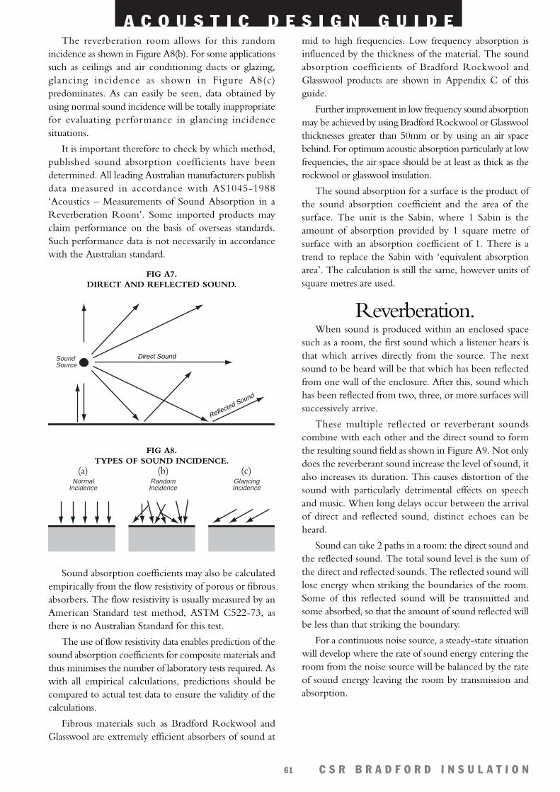
A C O U S T I C D E S I G N G U I D E
C S R B R A D F O R D I N S U L A T I O N61
The reverberation room allows for this randomincidence as shown in Figure A8(b). For some applicationssuch as ceilings and air conditioning ducts or glazing,glancing incidence as shown in Figure A8(c)predominates. As can easily be seen, data obtained byusing normal sound incidence will be totally inappropriatefor evaluating performance in glancing incidencesituations.
It is important therefore to check by which method,published sound absorption coefficients have beendetermined. All leading Australian manufacturers publishdata measured in accordance with AS1045-1988‘Acoustics – Measurements of Sound Absorption in aReverberation Room’. Some imported products mayclaim performance on the basis of overseas standards.Such performance data is not necessarily in accordancewith the Australian standard.
Sound absorption coefficients may also be calculatedempirically from the flow resistivity of porous or fibrousabsorbers. The flow resistivity is usually measured by anAmerican Standard test method, ASTM C522-73, asthere is no Australian Standard for this test.
The use of flow resistivity data enables prediction of thesound absorption coefficients for composite materials andthus minimises the number of laboratory tests required. Aswith all empirical calculations, predictions should becompared to actual test data to ensure the validity of thecalculations.
Fibrous materials such as Bradford Rockwool andGlasswool are extremely efficient absorbers of sound at
mid to high frequencies. Low frequency absorption isinfluenced by the thickness of the material. The soundabsorption coefficients of Bradford Rockwool andGlasswool products are shown in Appendix C of thisguide.
Further improvement in low frequency sound absorptionmay be achieved by using Bradford Rockwool or Glasswoolthicknesses greater than 50mm or by using an air spacebehind. For optimum acoustic absorption particularly at lowfrequencies, the air space should be at least as thick as therockwool or glasswool insulation.
The sound absorption for a surface is the product ofthe sound absorption coefficient and the area of thesurface. The unit is the Sabin, where 1 Sabin is theamount of absorption provided by 1 square metre ofsurface with an absorption coefficient of 1. There is atrend to replace the Sabin with ‘equivalent absorptionarea’. The calculation is still the same, however units ofsquare metres are used.
Reverberation.When sound is produced within an enclosed space
such as a room, the first sound which a listener hears isthat which arrives directly from the source. The nextsound to be heard will be that which has been reflectedfrom one wall of the enclosure. After this, sound whichhas been reflected from two, three, or more surfaces willsuccessively arrive.
These multiple reflected or reverberant soundscombine with each other and the direct sound to formthe resulting sound field as shown in Figure A9. Not onlydoes the reverberant sound increase the level of sound, italso increases its duration. This causes distortion of thesound with particularly detrimental effects on speechand music. When long delays occur between the arrivalof direct and reflected sound, distinct echoes can beheard.
Sound can take 2 paths in a room: the direct sound andthe reflected sound. The total sound level is the sum ofthe direct and reflected sounds. The reflected sound willlose energy when striking the boundaries of the room.Some of this reflected sound will be transmitted andsome absorbed, so that the amount of sound reflected willbe less than that striking the boundary.
For a continuous noise source, a steady-state situationwill develop where the rate of sound energy entering theroom from the noise source will be balanced by the rateof sound energy leaving the room by transmission andabsorption.
SoundSource
Direct Sound
Reflected Sound
FIG A7. DIRECT AND REFLECTED SOUND.
FIG A8. TYPES OF SOUND INCIDENCE.
(a) (b) (c)Normal
IncidenceRandomIncidence
GlancingIncidence
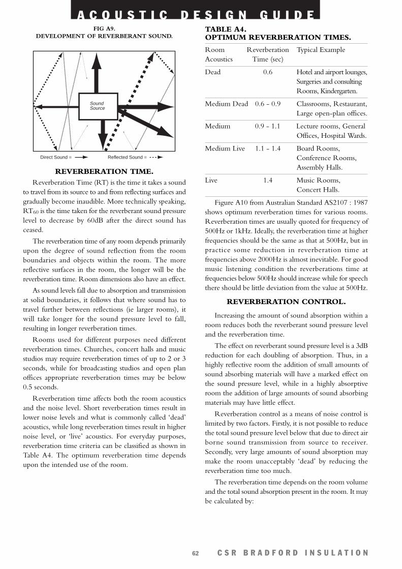
A C O U S T I C D E S I G N G U I D E
C S R B R A D F O R D I N S U L A T I O N62
REVERBERATION TIME.Reverberation Time (RT) is the time it takes a sound
to travel from its source to and from reflecting surfaces andgradually become inaudible. More technically speaking,RT60 is the time taken for the reverberant sound pressurelevel to decrease by 60dB after the direct sound hasceased.
The reverberation time of any room depends primarilyupon the degree of sound reflection from the roomboundaries and objects within the room. The morereflective surfaces in the room, the longer will be thereverberation time. Room dimensions also have an effect.
As sound levels fall due to absorption and transmissionat solid boundaries, it follows that where sound has totravel further between reflections (ie larger rooms), itwill take longer for the sound pressure level to fall,resulting in longer reverberation times.
Rooms used for different purposes need differentreverberation times. Churches, concert halls and musicstudios may require reverberation times of up to 2 or 3seconds, while for broadcasting studios and open planoffices appropriate reverberation times may be below0.5 seconds.
Reverberation time affects both the room acousticsand the noise level. Short reverberation times result inlower noise levels and what is commonly called ‘dead’acoustics, while long reverberation times result in highernoise level, or ‘live’ acoustics. For everyday purposes,reverberation time criteria can be classified as shown inTable A4. The optimum reverberation time dependsupon the intended use of the room.
TABLE A4. OPTIMUM REVERBERATION TIMES.
Room Reverberation Typical ExampleAcoustics Time (sec)
Dead 0.6 Hotel and airport lounges,Surgeries and consultingRooms, Kindergarten.
Medium Dead 0.6 - 0.9 Classrooms, Restaurant,Large open-plan offices.
Medium 0.9 - 1.1 Lecture rooms, GeneralOffices, Hospital Wards.
Medium Live 1.1 - 1.4 Board Rooms,Conference Rooms,Assembly Halls.
Live 1.4 Music Rooms,Concert Halls.
Figure A10 from Australian Standard AS2107 : 1987shows optimum reverberation times for various rooms.Reverberation times are usually quoted for frequency of500Hz or 1kHz. Ideally, the reverberation time at higherfrequencies should be the same as that at 500Hz, but inpractice some reduction in reverberation time atfrequencies above 2000Hz is almost inevitable. For goodmusic listening condition the reverberations time atfrequencies below 500Hz should increase while for speechthere should be little deviation from the value at 500Hz.
REVERBERATION CONTROL.
Increasing the amount of sound absorption within aroom reduces both the reverberant sound pressure leveland the reverberation time.
The effect on reverberant sound pressure level is a 3dBreduction for each doubling of absorption. Thus, in ahighly reflective room the addition of small amounts ofsound absorbing materials will have a marked effect onthe sound pressure level, while in a highly absorptiveroom the addition of large amounts of sound absorbingmaterials may have little effect.
Reverberation control as a means of noise control islimited by two factors. Firstly, it is not possible to reducethe total sound pressure level below that due to direct airborne sound transmission from source to receiver.Secondly, very large amounts of sound absorption maymake the room unacceptably ‘dead’ by reducing thereverberation time too much.
The reverberation time depends on the room volumeand the total sound absorption present in the room. It maybe calculated by:
Direct Sound = Reflected Sound =
SoundSource
FIG A9. DEVELOPMENT OF REVERBERANT SOUND.
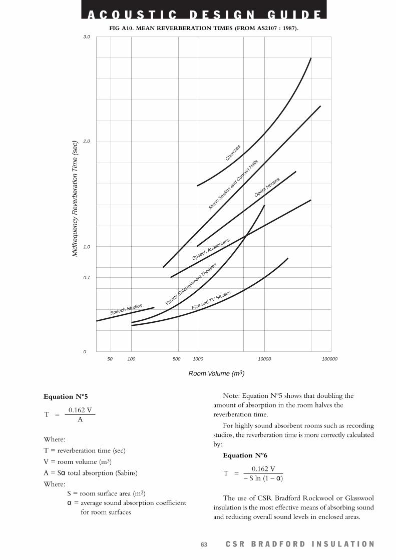
A C O U S T I C D E S I G N G U I D E
C S R B R A D F O R D I N S U L A T I O N63
Mid
freq
uenc
y R
ever
bera
tion
Tim
e (s
ec)
Room Volume (m3)
3.0
2.0
1.0
0.7
0
50 100 500 1000 10000 100000
Churc
hes
Music
Studio
s and
Con
cert
Halls
Opera Houses
Speech Auditoriums
Variety
Entertainment T
heatres
Speech Studios Film and TV Studios
FIG A10. MEAN REVERBERATION TIMES (FROM AS2107 : 1987).
Equation Nº5
Where:
T = reverberation time (sec)
V = room volume (m3)
A = Sα total absorption (Sabins)
Where: S = room surface area (m2)α = average sound absorption coefficient
for room surfaces
0.162 VA
T =
Note: Equation Nº5 shows that doubling theamount of absorption in the room halves thereverberation time.
For highly sound absorbent rooms such as recordingstudios, the reverberation time is more correctly calculatedby:
Equation Nº6
The use of CSR Bradford Rockwool or Glasswoolinsulation is the most effective means of absorbing soundand reducing overall sound levels in enclosed areas.
0.162 V– S ln (1 – α)
T =
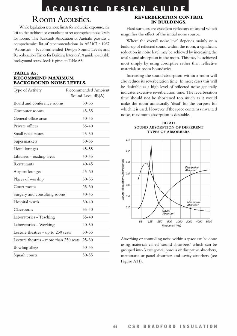
A C O U S T I C D E S I G N G U I D E
C S R B R A D F O R D I N S U L A T I O N64
Room Acoustics.While legislation sets noise limits for industrial exposure, it is
left to the architect or consultant to set appropriate noise levelsfor rooms. The Standards Association of Australia provides acomprehensive list of recommendations in AS2107 : 1987‘Acoustics - Recommended Design Sound Levels andReverberation Times for Building Interiors’. A guide to suitablebackground sound levels is given in Table A5.
TABLE A5. RECOMMEND MAXIMUMBACKGROUND NOISE LEVELS.
Type of Activity Recommended AmbientSound Level dB(A)
Board and conference rooms 30-35
Computer rooms 45-55
General office areas 40-45
Private offices 35-40
Small retail stores 45-50
Supermarkets 50-55
Hotel lounges 45-55
Libraries - reading areas 40-45
Restaurants 40-45
Airport lounges 45-60
Places of worship 30-35
Court rooms 25-30
Surgery and consulting rooms 40-45
Hospital wards 30-40
Classrooms 35-40
Laboratories - Teaching 35-40
Laboratories - Working 40-50
Lecture theatres - up to 250 seats 30-35
Lecture theatres - more than 250 seats 25-30
Bowling alleys 50-55
Squash courts 50-55
REVERBERATION CONTROLIN BUILDINGS.
Hard surfaces are excellent reflectors of sound whichmagnifies the effect of the initial noise source.
Where the overall noise level depends mainly on abuild-up of reflected sound within the room, a significantreduction in noise level may be achieved by increasing thetotal sound absorption in the room. This may be achievedmost simply by using absorptive rather than reflectivematerials at room boundaries.
Increasing the sound absorption within a room willalso reduce its reverberation time. In most cases this willbe desirable as a high level of reflected noise generallyindicates excessive reverberation time. The reverberationtime should not be shortened too much as it wouldmake the room unnaturally ‘dead’ for the purpose forwhich it is used. However if the space contains unwantednoise, maximum absorption is desirable.
Absorbing or controlling noise within a space can be doneusing materials called ‘sound absorbers’ which can begrouped into 3 categories; porous or dissipative absorbers,membrane or panel absorbers and cavity absorbers (seeFigure A11).
1.4
1.2
1.0
0.8
0.6
0.4
0.2
63 125 250 500 1000 2000 4000 8000Frequency (Hz)
Sou
nd A
bsor
ptio
n C
oeffi
cien
t (α)
CavityAbsorber
Dissipative Absorber
MembraneAbsorber
FIG A11. SOUND ABSORPTION OF DIFFERENT
TYPES OF ABSORBERS.
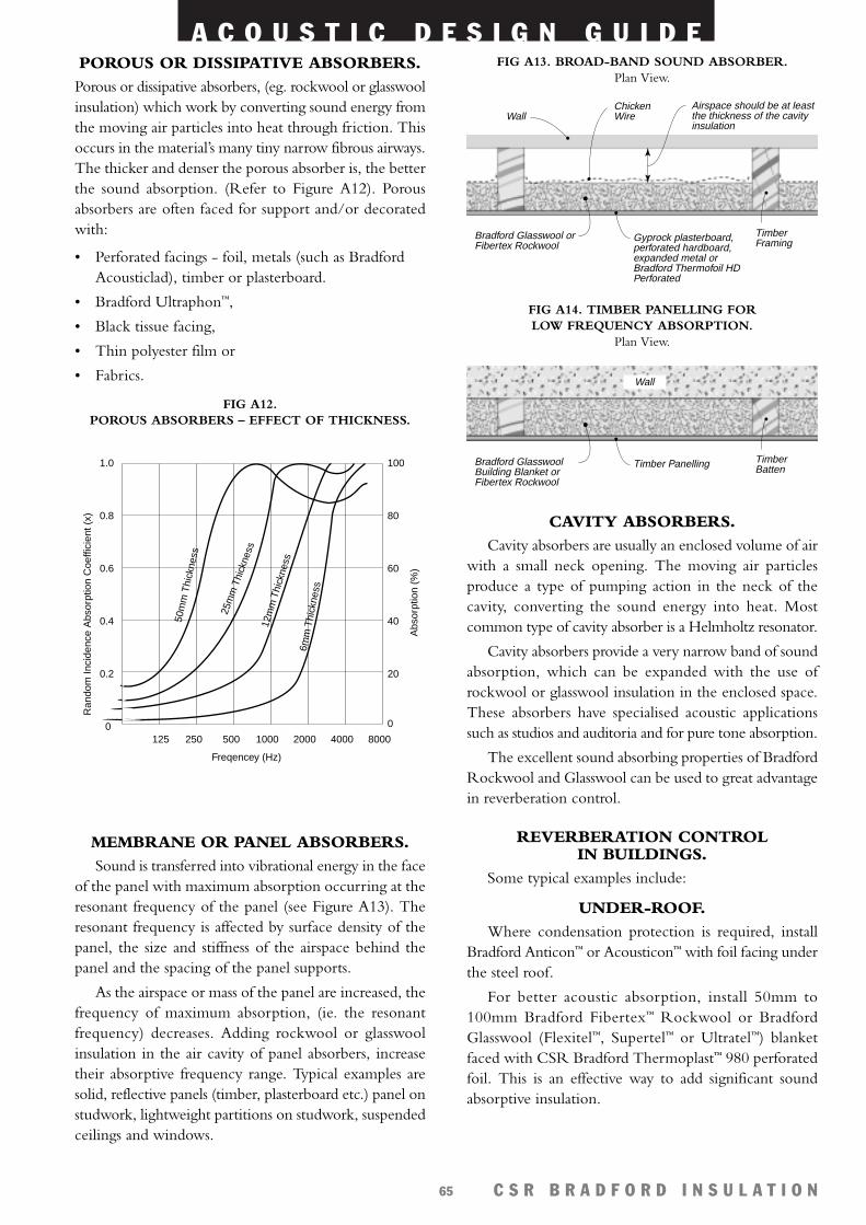
A C O U S T I C D E S I G N G U I D E
C S R B R A D F O R D I N S U L A T I O N65
POROUS OR DISSIPATIVE ABSORBERS.Porous or dissipative absorbers, (eg. rockwool or glasswoolinsulation) which work by converting sound energy fromthe moving air particles into heat through friction. Thisoccurs in the material’s many tiny narrow fibrous airways.The thicker and denser the porous absorber is, the betterthe sound absorption. (Refer to Figure A12). Porousabsorbers are often faced for support and/or decoratedwith:
• Perforated facings - foil, metals (such as BradfordAcousticlad), timber or plasterboard.
• Bradford Ultraphon™,
• Black tissue facing,
• Thin polyester film or
• Fabrics.
MEMBRANE OR PANEL ABSORBERS.Sound is transferred into vibrational energy in the face
of the panel with maximum absorption occurring at theresonant frequency of the panel (see Figure A13). Theresonant frequency is affected by surface density of thepanel, the size and stiffness of the airspace behind thepanel and the spacing of the panel supports.
As the airspace or mass of the panel are increased, thefrequency of maximum absorption, (ie. the resonantfrequency) decreases. Adding rockwool or glasswoolinsulation in the air cavity of panel absorbers, increasetheir absorptive frequency range. Typical examples aresolid, reflective panels (timber, plasterboard etc.) panel onstudwork, lightweight partitions on studwork, suspendedceilings and windows.
Bradford Glasswool orFibertex Rockwool
Wall
Timber FramingGyprock plasterboard,
perforated hardboard, expanded metal or Bradford Thermofoil HD Perforated
Airspace should be at least the thickness of the cavity insulation
ChickenWire
FIG A13. BROAD-BAND SOUND ABSORBER.Plan View.
Bradford Glasswool Building Blanket orFibertex Rockwool
Wall
Timber BattenTimber Panelling
FIG A14. TIMBER PANELLING FOR LOW FREQUENCY ABSORPTION.
Plan View.
CAVITY ABSORBERS.Cavity absorbers are usually an enclosed volume of air
with a small neck opening. The moving air particlesproduce a type of pumping action in the neck of thecavity, converting the sound energy into heat. Mostcommon type of cavity absorber is a Helmholtz resonator.
Cavity absorbers provide a very narrow band of soundabsorption, which can be expanded with the use ofrockwool or glasswool insulation in the enclosed space.These absorbers have specialised acoustic applicationssuch as studios and auditoria and for pure tone absorption.
The excellent sound absorbing properties of BradfordRockwool and Glasswool can be used to great advantagein reverberation control.
REVERBERATION CONTROL IN BUILDINGS.
Some typical examples include:
UNDER-ROOF.Where condensation protection is required, install
Bradford Anticon™ or Acousticon™ with foil facing underthe steel roof.
For better acoustic absorption, install 50mm to100mm Bradford Fibertex™ Rockwool or BradfordGlasswool (Flexitel™, Supertel™ or Ultratel™) blanketfaced with CSR Bradford Thermoplast™ 980 perforatedfoil. This is an effective way to add significant soundabsorptive insulation.
125 250 500 1000 2000 4000 80000
0.2
0.4
0.6
0.8
1.0
0
20
40
60
80
100
Ran
dom
Inci
denc
e A
bsor
ptio
n C
oeffi
cien
t (x)
50m
m T
hick
ness
25m
m T
hick
ness
12m
m T
hick
ness
6mm
Thi
ckne
ss
Abs
orpt
ion
(%)
Freqencey (Hz)
FIG A12. POROUS ABSORBERS – EFFECT OF THICKNESS.
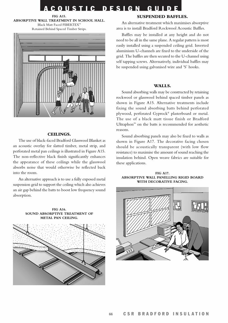
A C O U S T I C D E S I G N G U I D E
C S R B R A D F O R D I N S U L A T I O N66
CEILINGS.The use of black-faced Bradford Glasswool Blanket as
an acoustic overlay for slatted timber, metal strip, andperforated metal pan ceilings is illustrated in Figure A15.The non-reflective black finish significantly enhancesthe appearance of these ceilings while the glasswoolabsorbs noise that would otherwise be reflected backinto the room.
An alternative approach is to use a fully exposed metalsuspension grid to support the ceiling which also achievesan air gap behind the batts to boost low frequency soundabsorption.
FIG A17. ABSORPTIVE WALL PANELLING RIGID BOARD
WITH DECORATIVE FACING.
FIG A15. ABSORPTIVE WALL TREATMENT IN SCHOOL HALL.
Black Matt Faced FIBERTEX™
Retained Behind Spaced Timber Strips.
SUSPENDED BAFFLES.An alternative treatment which maximises absorptive
area is to install Bradford Rockwool Acoustic Baffles.
Baffles may be installed at any height and do notneed to be all in the same plane. A regular pattern is mosteasily installed using a suspended ceiling grid. Invertedaluminium U-channels are fixed to the underside of thegrid. The baffles are then secured to the U-channel usingself tapping screws. Alternatively, individual baffles maybe suspended using galvanised wire and ‘S’ hooks.
FIG A16. SOUND ABSORPTIVE TREATMENT OF
METAL PAN CEILING.
WALLS.Sound absorbing walls may be constructed by retaining
rockwool or glasswool behind spaced timber panels asshown in Figure A15. Alternative treatments includefixing the sound absorbing batts behind perforatedplywood, perforated Gyprock® plasterboard or metal.The use of a black matt tissue finish or BradfordUltraphon™ on the batts is recommended for aestheticreasons.
Sound absorbing panels may also be fixed to walls asshown in Figure A17. The decorative facing chosenshould be acoustically transparent (with low flowresistance) to maximise the amount of sound reaching theinsulation behind. Open weave fabrics are suitable forthese applications.
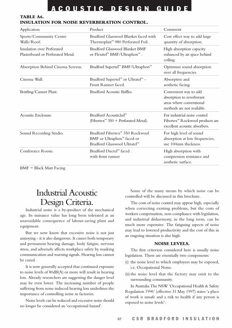
A C O U S T I C D E S I G N G U I D E
C S R B R A D F O R D I N S U L A T I O N67
Industrial AcousticDesign Criteria.
Industrial noise is a by-product of the mechanicalage. Its nuisance value has long been tolerated as anunavoidable consequence of labour-saving plant andequipment.
But we now know that excessive noise is not justannoying - it is also dangerous. It causes both temporaryand permanent hearing damage, body fatigue, nervousstress, and adversely affects workplace safety by maskingcommunication and warning signals. Hearing loss cannotbe cured.
It is now generally accepted that continued exposureto noise levels of 80dB(A) or more will result in hearingloss. Already researchers are suggesting the danger levelmay be even lower. The increasing number of peoplesuffering from noise induced hearing loss underlines theimportance of controlling noise in factories.
Noise levels can be reduced and excessive noise shouldno longer be considered an ‘occupational hazard’.
Some of the many means by which noise can becontrolled will be discussed in this brochure.
The costs of noise control may appear high, especiallywhen correcting existing problems, but the costs ofworkers compensation, non-compliance with legislation,and industrial disharmony, in the long term, can bemuch more expensive. The fatiguing aspects of noisemay lead to lowered productivity and the cost of this inan ongoing situation is also high.
NOISE LEVELS.The first criterion considered here is usually noise
legislation. There are essentially two components:
(i) the noise level to which employees may be exposed,i.e. Occupational Noise.
(ii) the noise level that the factory may emit to thesurrounding community.
In Australia The NSW ‘Occupational Health & SafetyRegulation 1996’ (effective 31 May 1997) states ‘a placeof work is unsafe and a risk to health if any person isexposed to noise levels’:
TABLE A6. INSULATION FOR NOISE REVERBERATION CONTROL.
Application Product Comment
Sports/Community Centre Bradford Glasswool Blanket faced with Cost effect way to add largeWalls/Roof. Thermoplast™ 980 Perforated Foil. quantity of absorption.
Insulation over Perforated Bradford Glasswool Blanket BMF High absorption capacityPlasterboard or Perforated Metal. or Flexitel™ BMF/Ultraphon™ . enhanced by air space behind
ceiling.
Absorption Behind Cinema Screens. Bradford Supertel™ BMF/Ultraphon™ Optimum sound absorptionover all frequencies.
Cinema Wall. Bradford Supertel™ or Ultratel™ - Absorptive andFront Runner faced. aesthetic facing.
Bottling/Canner Plant. Bradford Acoustic Baffles. Convenient way to add absorption to reverberantareas where conventionalmethods are not available.
Acoustic Enclosure. Bradford Acousticlad™ For industrial noise control (Fibertex™ 350 + Perforated Metal). Fibertex™ Rockwool products are
excellent acoustic absorbers.
Sound Recording Studio. Bradford Fibertex™ 350 Rockwool For high level of sound BMF or Ultraphon™ faced or absorption at low frequencies,Bradford Glasswool Ultratel™ use 100mm thickness.
Conference Room. Bradford Ductel™ faced . High absorption with with front runner compression resistance and
aesthetic surface.BMF = Black Matt Facing
A C O U S T I C D E S I G N G U I D E
C S R B R A D F O R D I N S U L A T I O N68
a) that exceed an 8 hour noise level equivalent of85dB(A) or
b) ‘Peak’ noise levels of 140dB (Lin) or more.
For every 3dB(A) above 85dB(A), the exposure timeis halved, so that four hours exposure would be permittedat 88dB(A) and two hours at 91dB(A) and so on.Conversely, every 3dB(A) lowering of the noise levelsdoubles the time for which employees may be exposed.Therefore 16 hours of exposure would permitted at82dB(A). Compliance with noise legislation does nottherefore automatically ensure that employees will notsuffer noise induced hearing loss.
Permitted noise emission levels depend upon thelocation of the factory and it’s proximity toresidences/offices nearby. The Environment ProtectionAuthority (EPA) sets noise criteria for noise emissionsfrom industry.
The character of the noise is also important. Highfrequency sounds are more annoying than sounds of lowfrequency, while noise with prominent tonal componentsis more annoying than broad band noise of the sameintensity. The hours of operation also affect the permittednoise emission levels. Lower levels apply at night thanduring the day.
Other aspects affected by noise level include:
SPEECH INTELLIGIBILITY.High noise levels above 70dB(A) can make verbal
communication extremely difficult and loss of speechintelligibility can occur. This leads to misunderstandingswhich can result in inefficient process operations, productlosses, unsafe working practices, and industrial unrest.
MACHINE OPERATION.The sounds emitted by many machines convey
important information to operators on the functioningof the machine. Excessive background noise may maskthese sounds, preventing early detection of machinemalfunction. Expensive repairs and loss of productivitymay result.
WARNING SIGNALS.Many warning signals or alarms rely on sound to
attract people’s attention. Most alarms now incorporateboth visual (e.g. flashing lights) and audio signals, but itis important to note that visual signals are only effectivefor the line of sight, while audio signals are designed toattract attention regardless of where an employee may belooking. High background noise levels may mask thesewarning signals, resulting in unsafe work practices andinefficient process operation.
CONCENTRATION.High noise levels are known to affect concentration
which leads to increased errors in machine operationand failure to detect quality defects in product. Lack ofconcentration can also be a safety hazard resulting ininjury to employees and equipment damage.
Each situation will have its own peculiarities so it isnot possible to set a universal permissible noise level forall factories. Consideration of the above factors, togetherwith the costs involved, should permit a responsibletarget noise level to be set.
Speech Privacy.The need to preserve confidentiality of conversation
arises in many situations. Discussions in conference roomsand executive offices should not be overheard. Peoplewaiting in airport lounges or hotel lobbies wish toconverse freely. Intimate diners do not wish to sharetheir conversation with others in the restaurant. Acousticalprivacy is paramount in residential situations where wallsor floors abut adjoining residences. Bedrooms in oneresidence need to be acoustically isolated from rooms inother residences to avoid annoyance. Similarly impactnoise on hard floors can irritate people in rooms below.
The level of speech privacy required will depend onthe particular situation. Three categories may beconsidered:
1. Partial coherence – small portions of the conversationmay be intelligible to an uninvolved listener, buthe/she will not be able to follow the conversation asa whole,
2. Incoherent – an uninvolved listener can hear thesound of conversation but it is not intelligible,
3. Inaudibility – no sound whatever can be heard by anuninvolved listener.
Speech privacy is a two-way consideration. It may berequired to protect the confidentiality of conversation (eg.a boardroom meeting) or on the other hand, to avoiddistraction of uninvolved listeners (eg. office workers orpeople in a library).
Typically in commercial applications, noises such asconversations, telephones ringing etc can be heard fromone office to another (also known as ‘crosstalk’). This cancause disruption, annoyance, and decreased productivity.Crosstalk usually occurs from sound flanking via the:
• light weight ceilings (refer to ‘Ceilings’, page 18 fordiagrams showing installation ).
• Air conditioning ducts (refer to ‘Air ConditioningNoise Control’, page 36).
• Windows and doors.
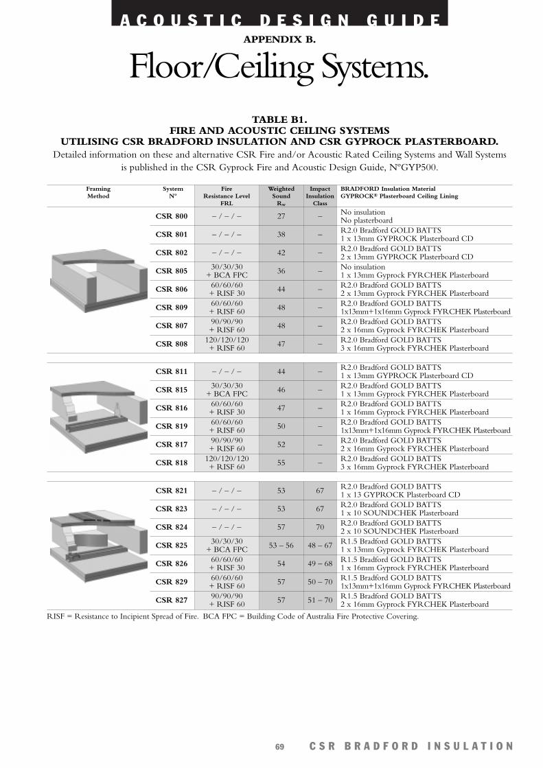
A C O U S T I C D E S I G N G U I D E
C S R B R A D F O R D I N S U L A T I O N69
APPENDIX B.
Floor/Ceiling Systems.
CSR 821 – / – / – 53 67
CSR 823 – / – / – 53 67
CSR 824 – / – / – 57 70
CSR 825 53 – 56 48 – 6730/30/30+ BCA FPC
CSR 829 57 50 – 7060/60/60+ RISF 60
CSR 826 54 49 – 6860/60/60+ RISF 30
CSR 827 57 51 – 7090/90/90+ RISF 60
System Fire Weighted Impact BRADFORD Insulation MaterialNº Resistance Level Sound Insulation GYPROCK® Plasterboard Ceiling Lining
FRL Rw Class
CSR 800 – / – / – 27 –
CSR 811 – / – / – 44 – R2.0 Bradford GOLD BATTS1 x 13mm GYPROCK Plasterboard CD
CSR 815 46 –
CSR 801 – / – / – 38 – R2.0 Bradford GOLD BATTS1 x 13mm GYPROCK Plasterboard CD
No insulationNo plasterboard
CSR 802 – / – / – 42 – R2.0 Bradford GOLD BATTS2 x 13mm GYPROCK Plasterboard CD
CSR 805 36 – No insulation1 x 13mm Gyprock FYRCHEK Plasterboard
30/30/30+ BCA FPC
30/30/30+ BCA FPC
CSR 819 50 –60/60/60+ RISF 60
CSR 816 47 –60/60/60+ RISF 30
CSR 817 52 –90/90/90+ RISF 60
CSR 818 55 –120/120/120+ RISF 60
60/60/60+ RISF 60
CSR 806 44 – R2.0 Bradford GOLD BATTS2 x 13mm Gyprock FYRCHEK Plasterboard
60/60/60+ RISF 30
CSR 809 48 – R2.0 Bradford GOLD BATTS1x13mm+1x16mm Gyprock FYRCHEK Plasterboard
90/90/90+ RISF 60CSR 807 48 – R2.0 Bradford GOLD BATTS
2 x 16mm Gyprock FYRCHEK Plasterboard120/120/120+ RISF 60CSR 808 47 – R2.0 Bradford GOLD BATTS
3 x 16mm Gyprock FYRCHEK Plasterboard
FramingMethod
RISF = Resistance to Incipient Spread of Fire. BCA FPC = Building Code of Australia Fire Protective Covering.
R2.0 Bradford GOLD BATTS1 x 10 SOUNDCHEK Plasterboard
R2.0 Bradford GOLD BATTS1 x 13 GYPROCK Plasterboard CD
R2.0 Bradford GOLD BATTS2 x 10 SOUNDCHEK Plasterboard
R1.5 Bradford GOLD BATTS1 x 16mm Gyprock FYRCHEK PlasterboardR1.5 Bradford GOLD BATTS1x13mm+1x16mm Gyprock FYRCHEK PlasterboardR1.5 Bradford GOLD BATTS2 x 16mm Gyprock FYRCHEK Plasterboard
R2.0 Bradford GOLD BATTS1 x 13mm Gyprock FYRCHEK PlasterboardR2.0 Bradford GOLD BATTS1 x 16mm Gyprock FYRCHEK PlasterboardR2.0 Bradford GOLD BATTS1x13mm+1x16mm Gyprock FYRCHEK PlasterboardR2.0 Bradford GOLD BATTS2 x 16mm Gyprock FYRCHEK PlasterboardR2.0 Bradford GOLD BATTS3 x 16mm Gyprock FYRCHEK Plasterboard
R1.5 Bradford GOLD BATTS1 x 13mm Gyprock FYRCHEK Plasterboard
TABLE B1. FIRE AND ACOUSTIC CEILING SYSTEMS
UTILISING CSR BRADFORD INSULATION AND CSR GYPROCK PLASTERBOARD.Detailed information on these and alternative CSR Fire and/or Acoustic Rated Ceiling Systems and Wall Systems
is published in the CSR Gyprock Fire and Acoustic Design Guide, NºGYP500.
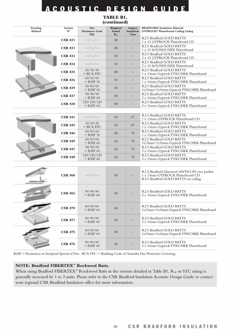
A C O U S T I C D E S I G N G U I D E
C S R B R A D F O R D I N S U L A T I O N70
CSR 831 – / – / – 48 –
CSR 833 – / – / – 48 –
CSR 832 – / – / – 53 –
CSR 834 – / – / – 53 –
CSR 835 48 –30/30/30+ BCA FPC
CSR 839 55 –60/60/60+ RISF 60
CSR 836 51 –60/60/60+ RISF 30
CSR 837 55 –90/90/90+ RISF 60
CSR 838 58 –120/120/120+ RISF 60
RISF = Resistance to Incipient Spread of Fire. BCA FPC = Building Code of Australia Fire Protective Covering.
R2.0 Bradford GOLD BATTS1 x 13 GYPROCK Plasterboard CD R2.0 Bradford GOLD BATTS1 x 10 SOUNDCHEK PlasterboardR2.0 Bradford GOLD BATTS2 x 13 GYPROCK Plasterboard CD R2.0 Bradford GOLD BATTS2 x 10 SOUNDCHEK PlasterboardR2.0 Bradford GOLD BATTS1 x 13mm Gyprock FYRCHEK PlasterboardR2.0 Bradford GOLD BATTS1 x 16mm Gyprock FYRCHEK PlasterboardR2.0 Bradford GOLD BATTS1x13mm+1x16mm Gyprock FYRCHEK PlasterboardR2.0 Bradford GOLD BATTS2 x 16mm Gyprock FYRCHEK PlasterboardR2.0 Bradford GOLD BATTS3 x 16mm Gyprock FYRCHEK Plasterboard
System Fire Weighted Impact BRADFORD Insulation MaterialNº Resistance Level Sound Insulation GYPROCK® Plasterboard Ceiling Lining
FRL Rw Class
FramingMethod
CSR 860 – / – / – 50 –R1.5 Bradford Glasswool ANTICON over purlins1 x 13mm GYPROCK Plasterboard CDR2.0 Bradford GOLD BATTS on ceiling
CSR 870 44 – R2.0 Bradford GOLD BATTS1x13mm+1x16mm Gyprock FYRCHEK Plasterboard
60/60/60+ RISF 60
CSR 871 44 – R2.0 Bradford GOLD BATTS2 x 16mm Gyprock FYRCHEK Plasterboard
90/90/90+ RISF 60
CSR 875 49 – R2.0 Bradford GOLD BATTS1x13mm+1x16mm Gyprock FYRCHEK Plasterboard
60/60/60+ RISF 60
CSR 876 49 – R2.0 Bradford GOLD BATTS2 x 16mm Gyprock FYRCHEK Plasterboard
90/90/90+ RISF 60
CSR 865 49 –90/90/90+ RISF 60
R2.0 Bradford GOLD BATTS2 x 16mm Gyprock FYRCHEK Plasterboard
CSR 841 – / – / – 54 67 R2.0 Bradford GOLD BATTS1 x 13mm GYPROCK Plasterboard CD
CSR 845 54 67 R2.0 Bradford GOLD BATTS1 x 13mm Gyprock FYRCHEK Plasterboard
30/30/30+ BCA FPC
CSR 849 62 70 R2.0 Bradford GOLD BATTS1x13mm+1x16mm Gyprock FYRCHEK Plasterboard
60/60/60+ RISF 60
CSR 846 58 70 R2.0 Bradford GOLD BATTS1 x 16mm Gyprock FYRCHEK Plasterboard
60/60/60+ RISF 30
CSR 847 62 73 R2.0 Bradford GOLD BATTS2 x 16mm Gyprock FYRCHEK Plasterboard
90/90/90+ RISF 60
CSR 848 62 75 R2.0 Bradford GOLD BATTS3 x 16mm Gyprock FYRCHEK Plasterboard
120/120/120+ RISF 60
NOTE: Bradford FIBERTEX™ Rockwool Batts.When using Bradford FIBERTEX™ Rockwool Batts in the systems detailed in Table B1, Rw or STC rating isgenerally increased by 1 to 3 units. Please refer to the CSR Bradford Insulation Acoustic Design Guide or contactyour regional CSR Bradford Insulation office for more information.
TABLE B1. (continued)
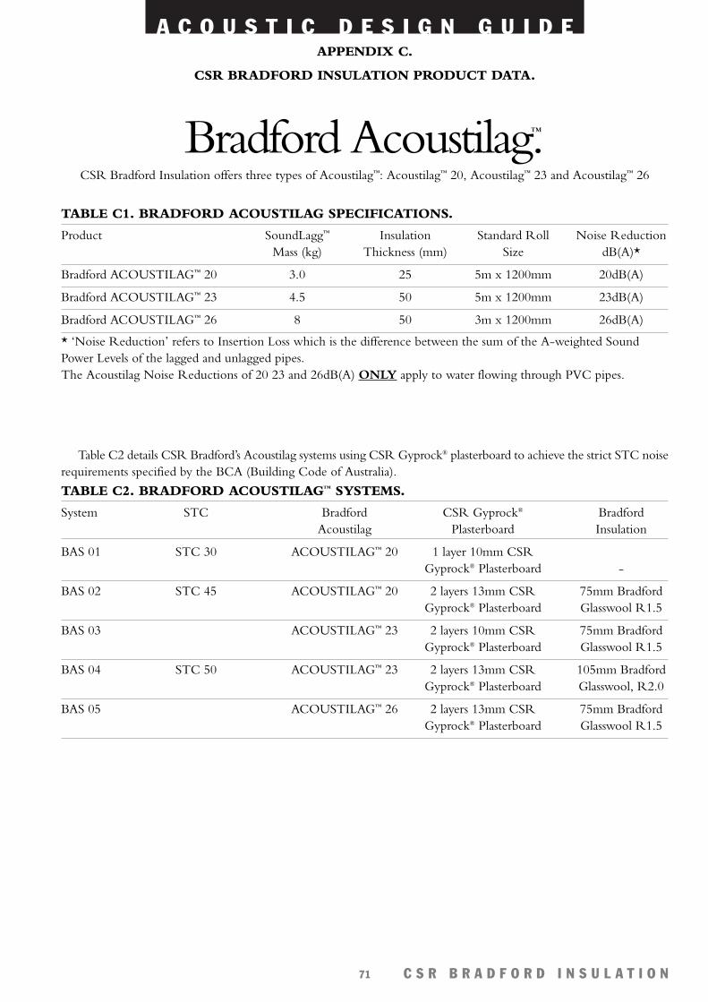
A C O U S T I C D E S I G N G U I D E
C S R B R A D F O R D I N S U L A T I O N71
Table C2 details CSR Bradford’s Acoustilag systems using CSR Gyprock® plasterboard to achieve the strict STC noiserequirements specified by the BCA (Building Code of Australia).
TABLE C1. BRADFORD ACOUSTILAG SPECIFICATIONS.
Product SoundLagg™ Insulation Standard Roll Noise ReductionMass (kg) Thickness (mm) Size dB(A)*
Bradford ACOUSTILAG™ 20 3.0 25 5m x 1200mm 20dB(A)
Bradford ACOUSTILAG™ 23 4.5 50 5m x 1200mm 23dB(A)
Bradford ACOUSTILAG™ 26 8 50 3m x 1200mm 26dB(A)
* ‘Noise Reduction’ refers to Insertion Loss which is the difference between the sum of the A-weighted SoundPower Levels of the lagged and unlagged pipes.The Acoustilag Noise Reductions of 20 23 and 26dB(A) ONLY apply to water flowing through PVC pipes.
TABLE C2. BRADFORD ACOUSTILAG™ SYSTEMS.
System STC Bradford CSR Gyprock® BradfordAcoustilag Plasterboard Insulation
BAS 01 STC 30 ACOUSTILAG™ 20 1 layer 10mm CSRGyprock® Plasterboard -
BAS 02 STC 45 ACOUSTILAG™ 20 2 layers 13mm CSR 75mm BradfordGyprock® Plasterboard Glasswool R1.5
BAS 03 ACOUSTILAG™ 23 2 layers 10mm CSR 75mm BradfordGyprock® Plasterboard Glasswool R1.5
BAS 04 STC 50 ACOUSTILAG™ 23 2 layers 13mm CSR 105mm BradfordGyprock® Plasterboard Glasswool, R2.0
BAS 05 ACOUSTILAG™ 26 2 layers 13mm CSR 75mm BradfordGyprock® Plasterboard Glasswool R1.5
APPENDIX C.
CSR BRADFORD INSULATION PRODUCT DATA.
CSR Bradford Insulation offers three types of Acoustilag™: Acoustilag™ 20, Acoustilag™ 23 and Acoustilag™ 26
Bradford Acoustilag™.
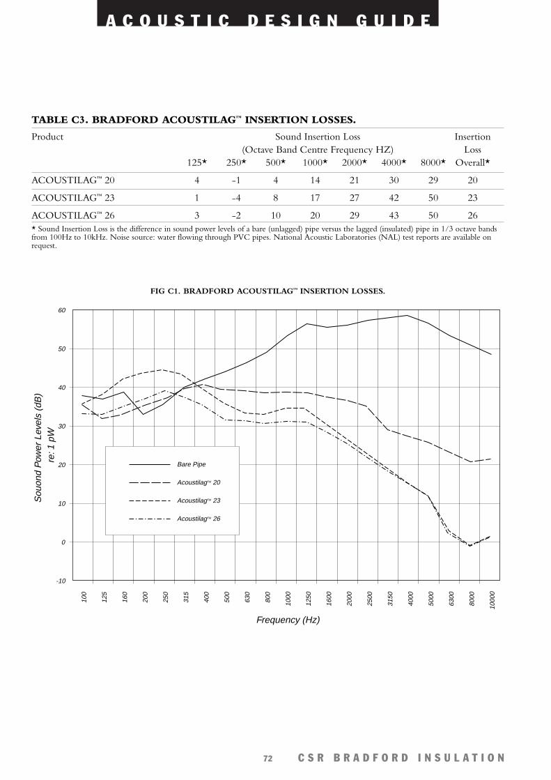
A C O U S T I C D E S I G N G U I D E
C S R B R A D F O R D I N S U L A T I O N72
60
50
40
30
20
10
0
-10
100
125
160
200
250
315
400
500
630
800
1000
1250
1600
2000
2500
3150
4000
5000
6300
8000
1000
0
Frequency (Hz)
Sou
ond
Pow
er L
evel
s (d
B)
re: 1
pW
Bare Pipe
AcoustilagTM 20
AcoustilagTM 23
AcoustilagTM 26
FIG C1. BRADFORD ACOUSTILAG™ INSERTION LOSSES.
TABLE C3. BRADFORD ACOUSTILAG™ INSERTION LOSSES.
Product Sound Insertion Loss Insertion(Octave Band Centre Frequency HZ) Loss
125* 250* 500* 1000* 2000* 4000* 8000* Overall*
ACOUSTILAG™ 20 4 -1 4 14 21 30 29 20
ACOUSTILAG™ 23 1 -4 8 17 27 42 50 23
ACOUSTILAG™ 26 3 -2 10 20 29 43 50 26* Sound Insertion Loss is the difference in sound power levels of a bare (unlagged) pipe versus the lagged (insulated) pipe in 1/3 octave bandsfrom 100Hz to 10kHz. Noise source: water flowing through PVC pipes. National Acoustic Laboratories (NAL) test reports are available onrequest.
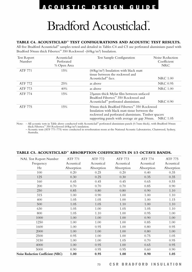
A C O U S T I C D E S I G N G U I D E
C S R B R A D F O R D I N S U L A T I O N73
Bradford Acousticlad™.TABLE C4. ACOUSTICLAD™ TEST CONFIGURATIONS AND ACOUSTIC TEST RESULTS.All five Bradford Acousticlad™ samples tested and detailed in Tables C4 and C5 use perforated aluminium panel withBradford 50mm thick Fibertex™ 350 Rockwool -(60kg/m3) Insulation.
Test Report Acousticlad Test Sample Configuration Noise ReductionNumber Perforated Coefficient
% Open Area NRC
ATF 771 15% (60kg/m3) Insulation with black matttissue between the rockwool andAcousticlad™ face. NRC 1.00
ATF 772 25% as above NRC 0.95
ATF 773 40% as above NRC 1.00
ATF 774 15% 23µmm thick Mylar film between unfacedBradford Fibertex™ 350 Rockwool andAcousticlad™ perforated aluminium. NRC 0.90
ATF 775 15% 50mm thick Bradford Fibertex™ 350 RockwoolInsulation with black matt tissue between therockwool and perforated aluminium. Timber spacerssupporting panels with average air gap 30mm. NRC 1.05
Note: – All acoustic tests in Table above conducted with Acousticlad™ perforated aluminium panels (0.7mm thick), with Bradford 50mmthick Fibertex™ 350 Rockwool (60kg/m3) insulation.
– Acoustic tests (ATF 771-775) were conducted in reverberation room at the National Acoustic Laboratories, Chatswood, Sydney,Australia.
TABLE C5. ACOUSTICLAD™ ABSORPTION COEFFICIENTS IN 1/3 OCTAVE BANDS.
NAL Test Report Number ATF 771 ATF 772 ATF 773 ATF 774 ATF 775Frequency Acoustical Acoustical Acoustical Acoustical Acoustical
Hz Absorption Absorption Absorption Absorption Absorption100 0.20 0.25 0.20 0.40 0.35125 0.30 0.25 0.30 0.35 0.35160 0.45 0.45 0.45 0.65 0.55200 0.70 0.70 0.70 0.85 0.90250 0.85 0.80 0.80 0.90 1.10315 1.00 0.90 1.00 1.00 1.10400 1.05 1.05 1.00 1.00 1.15500 1.05 1.05 1.10 1.00 1.10630 1.05 1.00 1.05 1.05 1.10800 1.05 1.10 1.00 0.95 1.001000 1.00 1.00 1.00 0.90 1.001250 1.00 1.00 1.00 0.85 1.001600 1.00 0.95 1.00 0.80 0.952000 1.00 1.00 1.00 0.80 1.002500 0.95 1.00 1.00 0.75 1.053150 1.00 1.00 1.05 0.70 0.954000 1.00 0.95 1.00 0.65 0.955000 0.90 0.95 0.95 0.60 0.90
Noise Reduction Coefficient (NRC) 1.00 0.95 1.00 0.90 1.05
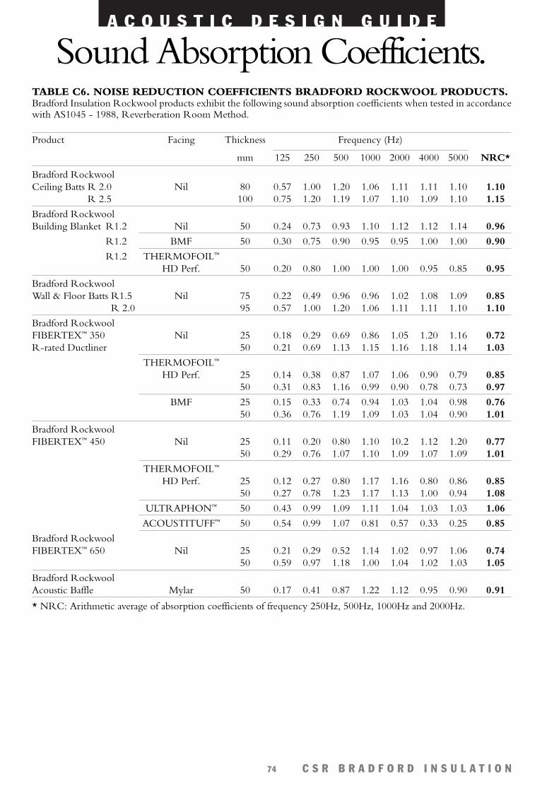
A C O U S T I C D E S I G N G U I D E
C S R B R A D F O R D I N S U L A T I O N74
Sound Absorption Coefficients.TABLE C6. NOISE REDUCTION COEFFICIENTS BRADFORD ROCKWOOL PRODUCTS.Bradford Insulation Rockwool products exhibit the following sound absorption coefficients when tested in accordancewith AS1045 - 1988, Reverberation Room Method.
Product Facing Thickness Frequency (Hz)
mm 125 250 500 1000 2000 4000 5000 NRC*
Bradford Rockwool Ceiling Batts R 2.0 Nil 80 0.57 1.00 1.20 1.06 1.11 1.11 1.10 1.10
R 2.5 100 0.75 1.20 1.19 1.07 1.10 1.09 1.10 1.15
Bradford Rockwool Building Blanket R1.2 Nil 50 0.24 0.73 0.93 1.10 1.12 1.12 1.14 0.96
R1.2 BMF 50 0.30 0.75 0.90 0.95 0.95 1.00 1.00 0.90
R1.2 THERMOFOIL™
HD Perf. 50 0.20 0.80 1.00 1.00 1.00 0.95 0.85 0.95
Bradford Rockwool Wall & Floor Batts R1.5 Nil 75 0.22 0.49 0.96 0.96 1.02 1.08 1.09 0.85
R 2.0 95 0.57 1.00 1.20 1.06 1.11 1.11 1.10 1.10
Bradford Rockwool FIBERTEX™ 350 Nil 25 0.18 0.29 0.69 0.86 1.05 1.20 1.16 0.72R-rated Ductliner 50 0.21 0.69 1.13 1.15 1.16 1.18 1.14 1.03
THERMOFOIL™
HD Perf. 25 0.14 0.38 0.87 1.07 1.06 0.90 0.79 0.8550 0.31 0.83 1.16 0.99 0.90 0.78 0.73 0.97
BMF 25 0.15 0.33 0.74 0.94 1.03 1.04 0.98 0.7650 0.36 0.76 1.19 1.09 1.03 1.04 0.90 1.01
Bradford Rockwool FIBERTEX™ 450 Nil 25 0.11 0.20 0.80 1.10 10.2 1.12 1.20 0.77
50 0.29 0.76 1.07 1.10 1.09 1.07 1.09 1.01
THERMOFOIL™
HD Perf. 25 0.12 0.27 0.80 1.17 1.16 0.80 0.86 0.8550 0.27 0.78 1.23 1.17 1.13 1.00 0.94 1.08
ULTRAPHON™ 50 0.43 0.99 1.09 1.11 1.04 1.03 1.03 1.06
ACOUSTITUFF™ 50 0.54 0.99 1.07 0.81 0.57 0.33 0.25 0.85
Bradford Rockwool FIBERTEX™ 650 Nil 25 0.21 0.29 0.52 1.14 1.02 0.97 1.06 0.74
50 0.59 0.97 1.18 1.00 1.04 1.02 1.03 1.05
Bradford Rockwool Acoustic Baffle Mylar 50 0.17 0.41 0.87 1.22 1.12 0.95 0.90 0.91
* NRC: Arithmetic average of absorption coefficients of frequency 250Hz, 500Hz, 1000Hz and 2000Hz.
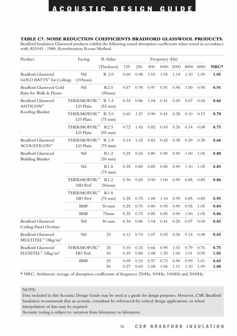
A C O U S T I C D E S I G N G U I D E
C S R B R A D F O R D I N S U L A T I O N75
TABLE C7. NOISE REDUCTION COEFFICIENTS BRADFORD GLASSWOOL PRODUCTS.Bradford Insulation Glasswool products exhibit the following sound absorption coefficients when tested in accordancewith AS1045 : 1988, Reverberation Room Method.
Product Facing R-Value Frequency (Hz)
(Thickness) 125 250 500 1000 2000 4000 5000 NRC*
Bradford Glasswool Nil R 2.0 0.60 0.98 1.03 1.05 1.14 1.10 1.09 1.05GOLD BATTS™ for Ceilings (105mm)
Bradford Glasswool Gold Nil R2.0 0.57 0.78 0.97 0.91 0.96 1.00 0.95 0.91Batts for Walls & Floors (95mm)
Bradford Glasswool THERMOFOIL™ R 1.5 0.34 0.86 1.04 0.41 0.20 0.07 0.04 0.66ANTICON™ LD Plain (55 mm)Roofing Blanket THERMOFOIL™ R 2.0 0.60 1.21 0.90 0.41 0.28 0.10 0.12 0.70
LD Plain (75 mm)
THERMOFOIL™ R2.5 0.72 1.43 0.82 0.43 0.26 0.14 0.08 0.75` LD Plain (95 mm)
Bradford Glasswool THERMOFOIL™ R 1.8 0.14 1.02 0.82 0.42 0.38 0.29 0.38 0.66ACOUSTICON™ LD Plain (75 mm)
Bradford Glasswool Nil R1.2 0.25 0.65 0.80 0.90 0.90 1.00 1.05 0.80Building Blanket (50 mm)
Nil R1.8 0.35 0.80 0.85 0.90 0.90 1.10 1.05 0.85(75 mm)
THERMOFOIL™ R1.2 0.30 0.65 0.90 1.00 0.90 0.85 0.85 0.86HD Perf (50mm)
THERMOFOIL™ R1.8HD Perf (75 mm) 0.35 0.75 1.00 1.10 0.95 0.85 0.85 0.95
BMF 50 mm 0.25 0.70 0.80 0.95 0.90 0.95 1.05 0.84
BMF 75mm 0.35 0.75 0.85 0.85 0.90 1.00 1.05 0.86
Bradford Glasswool Nil 50 mm 0.34 0.86 1.04 0.41 0.20 0.07 0.04 0.65Ceiling Panel Overlays
Bradford Glasswool Nil 25 0.12 0.74 1.07 0.52 0.26 0.14 0.08 0.65MULTITEL™ 18kg/m3
Bradford Glasswool THERMOFOIL™ 25 0.10 0.33 0.66 0.90 1.03 0.79 0.76 0.75FLEXITEL™ 24kg/m3 HD Perf. 50 0.39 0.84 1.08 1.20 1.06 1.01 0.95 1.05
BMF 25 0.09 0.33 0.57 0.73 0.90 0.99 1.01 0.6550 0.27 0.69 1.08 1.06 1.11 1.10 1.09 1.00
* NRC: Arithmetic average of absorption coefficients of frequency 250Hz, 500Hz, 1000Hz and 2000Hz.
NOTE:Data included in this Acoustic Design Guide may be used as a guide for design purposes. However, CSR BradfordInsulation recommends that an acoustic consultant be referenced for critical design applications, or whereinterpolation of data may be required.Acoustic testing is subject to variation from laboratory to laboratory.
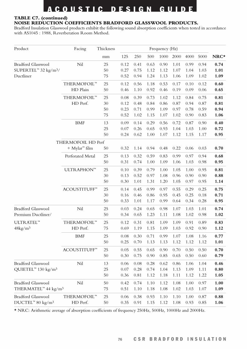
A C O U S T I C D E S I G N G U I D E
C S R B R A D F O R D I N S U L A T I O N76
TABLE C7. (continued)NOISE REDUCTION COEFFICIENTS BRADFORD GLASSWOOL PRODUCTS.Bradford Insulation Glasswool products exhibit the following sound absorption coefficients when tested in accordancewith AS1045 : 1988, Reverberation Room Method.
Product Facing Thickness Frequency (Hz)
mm 125 250 500 1000 2000 4000 5000 NRC*
Bradford Glasswool Nil 25 0.12 0.41 0.63 0.90 1.01 0.99 0.94 0.74SUPERTEL™ 32 kg/m3/ 50 0.27 0.75 1.12 1.12 1.07 1.04 1.03 1.01Ductliner 75 0.52 0.94 1.24 1.13 1.06 1.09 1.02 1.09
THERMOFOIL™ 25 0.12 0.56 1.18 0.53 0.17 0.10 0.12 0.60HD Plain 50 0.46 1.10 0.92 0.46 0.19 0.09 0.06 0.65
THERMOFOIL™ 25 0.08 0.39 0.73 1.02 1.12 0.84 0.75 0.81HD Perf. 30 0.12 0.48 0.84 0.86 0.87 0.94 0.87 0.81
50 0.23 0.71 0.99 1.09 0.97 0.78 0.59 0.9475 0.52 1.02 1.15 1.07 1.02 0.90 0.83 1.06
BMF 13 0.09 0.14 0.29 0.56 0.72 0.87 0.90 0.4025 0.07 0.26 0.65 0.93 1.04 1.03 1.00 0.7250 0.24 0.62 1.00 1.07 1.12 1.15 1.17 0.95
THERMOFOIL HD Perf + Mylar™ film 50 0.32 1.14 0.94 0.48 0.22 0.06 0.03 0.70
Perforated Metal 25 0.13 0.32 0.59 0.83 0.99 0.97 0.94 0.6850 0.31 0.74 1.00 1.09 1.06 1.03 0.98 0.95
ULTRAPHON™ 25 0.10 0.39 0.79 1.00 1.05 1.00 0.95 0.8130 0.13 0.52 0.97 1.08 0.96 0.90 0.90 0.8850 0.30 1.01 1.31 1.20 1.05 0.97 0.95 1.14
ACOUSTITUFF™ 25 0.14 0.45 0.99 0.97 0.55 0.29 0.25 0.7530 0.16 0.46 0.86 0.95 0.45 0.25 0.18 0.7150 0.33 1.01 1.17 0.99 0.64 0.34 0.28 0.95
Bradford Glasswool Nil 25 0.03 0.24 0.65 0.98 1.07 1.03 1.01 0.74Premium Ductliner/ 50 0.34 0.65 1.23 1.11 1.08 1.02 0.98 1.02
ULTRATEL™ THERMOFOIL™ 25 0.12 0.31 0.81 1.09 1.09 0.91 0.89 0.8348kg/m3 HD Perf. 75 0.69 1.19 1.15 1.09 1.03 0.92 0.90 1.12
BMF 25 0.08 0.30 0.71 0.99 1.07 1.08 1.16 0.7750 0.25 0.70 1.13 1.13 1.12 1.12 1.12 1.01
ACOUSTITUFF™ 25 0.05 0.55 0.65 0.90 0.70 0.50 0.50 0.7050 0.30 0.75 0.90 0.85 0.65 0.50 0.60 0.79
Bradford Glasswool Nil 13 0.06 0.08 0.28 0.62 0.86 1.06 1.04 0.46QUIETEL™ 130 kg/m3 25 0.07 0.28 0.74 1.04 1.13 1.09 1.11 0.80
50 0.36 0.81 1.12 1.18 1.11 1.12 1.22 1.05
Bradford Glasswool Nil 50 0.42 0.74 1.10 1.12 1.08 1.00 0.97 1.00THERMATEL™ 44 kg/m3 75 0.51 1.10 1.18 1.08 1.02 1.03 1.07 1.09
Bradford Glasswool THERMOFOIL™ 25 0.06 0.38 0.93 1.10 1.10 1.00 0.87 0.88DUCTEL™ 80 kg/m3 HD Perf. 50 0.35 0.91 1.15 1.12 1.08 0.93 0.85 1.06
* NRC: Arithmetic average of absorption coefficients of frequency 250Hz, 500Hz, 1000Hz and 2000Hz.
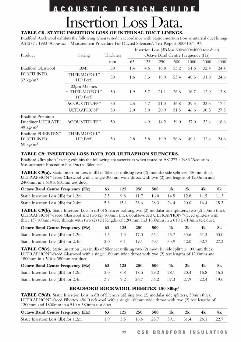
A C O U S T I C D E S I G N G U I D E
C S R B R A D F O R D I N S U L A T I O N77
Insertion Loss Data.TABLE C8. STATIC INSERTION LOSS OF INTERNAL DUCT LININGS.Bradford Rockwool exhibits the following when tested in accordance with Static Insertion Loss as internal duct liningsAS1277 : 1983 ‘Acoustics - Measurement Procedure For Ducted Silencers’. Test Report 300610/1-97.
Octave Band Centre Frequency (Hz) 63 125 250 500 1k 2k 4k 8k
Static Insertion Loss (dB) for 1.2m 2.5 9.8 11.7 16.0 14.5 12.8 11.5 11.3
Static Insertion Loss (dB) for 2.4m 5.3 15.1 23.6 28.3 24.4 20.0 16.4 15.3
Insertion Loss (dB loss 600x600x4000 test duct)Product Facing Thickness Octave Band Centre Frequency (Hz)
mm 63 125 250 500 1000 2000 4000
Bradford Glasswool BMF 50 1.4 4.6 16.8 53.2 51.6 32.4 24.4DUCTLINER THERMOFOIL™
32 kg/m3 HD Perf.50 1.6 5.3 18.9 53.4 48.3 31.8 24.6
23µm Melinex+ THERMOFOIL™ 50 1.9 5.7 21.1 26.6 16.7 12.9 12.8
HD Perf.
ACOUSTITUFF™ 50 2.5 4.7 21.3 46.8 39.3 23.3 17.4
ULTRAPHON™ 50 2.0 5.0 20.9 51.5 46.6 30.3 27.5
Bradford Premium Ductliner ULTRATEL ACOUSTITUFF™ 50 – 4.9 14.2 39.0 37.0 22.4 18.648 kg/m3
Bradford FIBERTEX™ THERMOFOIL™
DUCTLINER HD Perf. 50 2.8 5.8 19.9 56.6 49.1 32.4 24.660 kg/m3
TABLE C9(a). Static Insertion Loss in dB of Silencer utilising two (2) modular side splitters, 150mm thickULTRAPHON™-faced Glasswool with a single 300mm wide throat with two (2) test lengths of 1200mm and2400mm in a 610 x 610mm test duct.
Octave Band Centre Frequency (Hz) 63 125 250 500 1k 2k 4k 8k
Static Insertion Loss (dB) for 1.2m 1.5 4.3 17.3 35.1 45.7 33.6 31.3 33.0
Static Insertion Loss (dB) for 2.4m 2.0 6.1 19.1 40.1 53.9 42.0 32.7 27.3
TABLE C9(b). Static Insertion Loss in dB of Silencer utilising two (2) modular side splitters, two (2) 50mm thickULTRAPHON™-faced Glasswool and two (2) 100mm thick double-sided ULTRAPHON™-faced splitters withthree (3) 100mm wide throats with two (2) test lengths of 1200mm and 1800mm in a 610 x 610mm test duct.
Octave Band Centre Frequency (Hz) 63 125 250 500 1k 2k 4k 8k
Static Insertion Loss (dB) for 1.2m 2.0 6.8 18.5 29.2 28.1 20.4 16.8 16.2
Static Insertion Loss (dB) for 2.4m 3.7 9.2 26.7 36.2 37.3 27.9 22.4 19.6
TABLE C9(c). Static Insertion Loss in dB of Silencer utilising two (2) modular side splitters, 100mm thickULTRAPHON™-faced Glasswool with a single 180mm wide throat with two (2) test lengths of 1200mm and1800mm in a 510 x 380mm test duct.
Octave Band Centre Frequency (Hz) 63 125 250 500 1k 2k 4k 8k
Static Insertion Loss (dB) for 1.2m 1.9 5.5 16.6 28.7 39.1 31.4 26.1 22.7
TABLE C9(d). Static Insertion Loss in dB of Silencer utilising two (2) modular side splitters, 50mm thickULTRAPHON™-faced Fibertex 450 Rockwool with a single 180mm wide throat with two (2) test lengths of1200mm and 1800mm in a 510 x 380mm test duct.
BRADFORD ROCKWOOL FIBERTEX 450 80kg2
TABLE C9: INSERTION LOSS DATA FOR ULTRAPHON SILENCERS.Bradford Ultraphon™ facing exhibits the following characteristics when tested to AS1277 : 1983 ‘Acoustics -Measurement Procedure For Ducted Silencers’.
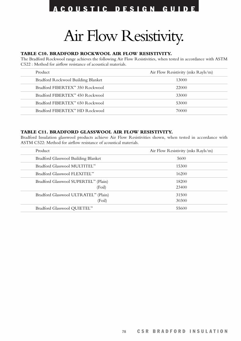
A C O U S T I C D E S I G N G U I D E
C S R B R A D F O R D I N S U L A T I O N78
Air Flow Resistivity.
TABLE C11. BRADFORD GLASSWOOL AIR FLOW RESISTIVITY.Bradford Insulation glasswool products achieve Air Flow Resistivities shown, when tested in accordance withASTM C522: Method for airflow resistance of acoustical materials.
TABLE C10. BRADFORD ROCKWOOL AIR FLOW RESISTIVITY.The Bradford Rockwool range achieves the following Air Flow Resistivities, when tested in accordance with ASTMC522 : Method for airflow resistance of acoustical materials.
Product Air Flow Resistivity (mks Rayls/m)
Bradford Rockwool Building Blanket 13000
Bradford FIBERTEX™ 350 Rockwool 22000
Bradford FIBERTEX™ 450 Rockwool 33000
Bradford FIBERTEX™ 650 Rockwool 53000
Bradford FIBERTEX™ HD Rockwool 70000
Product Air Flow Resistivity (mks Rayls/m)
Bradford Glasswool Building Blanket 5600
Bradford Glasswool MULTITEL™ 15300
Bradford Glasswool FLEXITEL™ 16200
Bradford Glasswool SUPERTEL™ (Plain) 18200(Foil) 23400
Bradford Glasswool ULTRATEL™ (Plain) 31500(Foil) 30300
Bradford Glasswool QUIETEL™ 55600
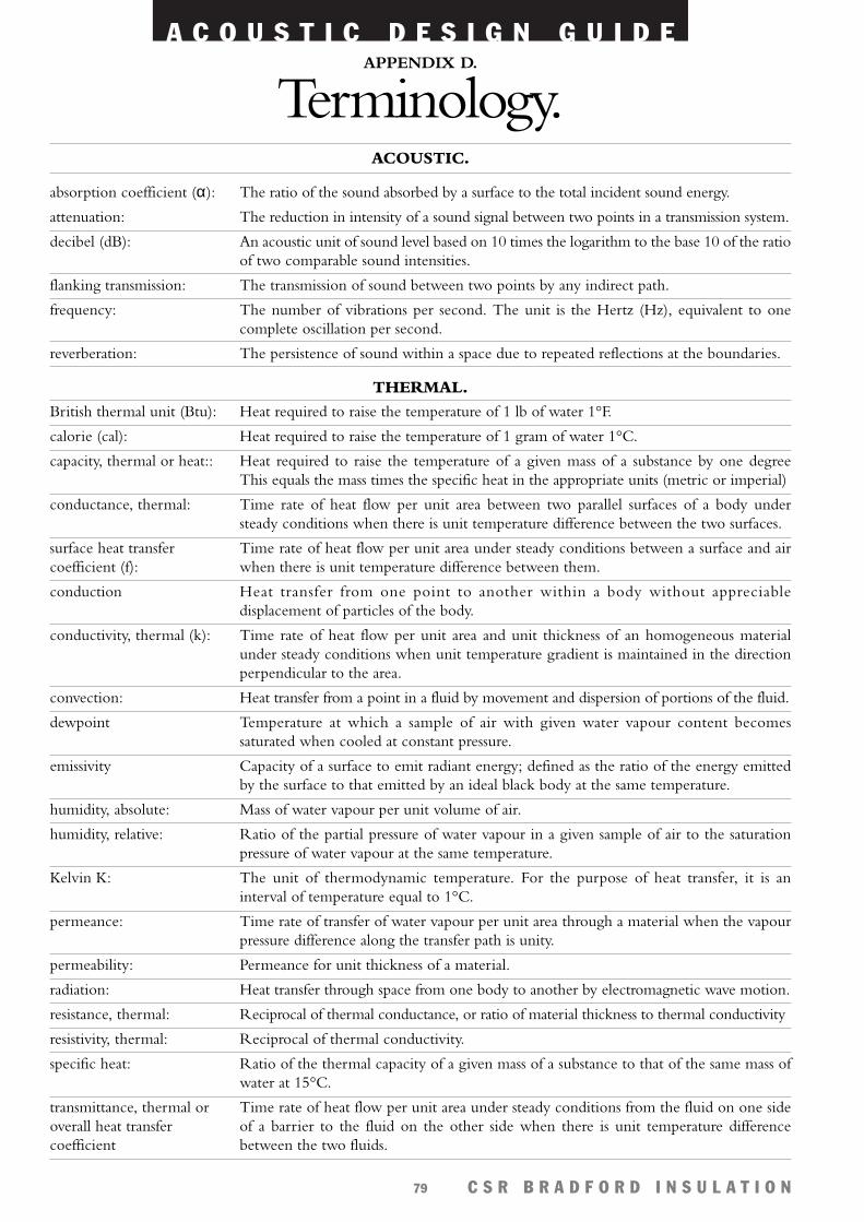
A C O U S T I C D E S I G N G U I D E
C S R B R A D F O R D I N S U L A T I O N79
absorption coefficient (α):
attenuation:
decibel (dB):
flanking transmission:
frequency:
reverberation:
British thermal unit (Btu):
calorie (cal):
capacity, thermal or heat::
conductance, thermal:
surface heat transfercoefficient (f):
conduction
conductivity, thermal (k):
convection:
dewpoint
emissivity
humidity, absolute:
humidity, relative:
Kelvin K:
permeance:
permeability:
radiation:
resistance, thermal:
resistivity, thermal:
specific heat:
transmittance, thermal oroverall heat transfercoefficient
The ratio of the sound absorbed by a surface to the total incident sound energy.
The reduction in intensity of a sound signal between two points in a transmission system.
An acoustic unit of sound level based on 10 times the logarithm to the base 10 of the ratioof two comparable sound intensities.
The transmission of sound between two points by any indirect path.
The number of vibrations per second. The unit is the Hertz (Hz), equivalent to onecomplete oscillation per second.
The persistence of sound within a space due to repeated reflections at the boundaries.
Heat required to raise the temperature of 1 lb of water 1°F.
Heat required to raise the temperature of 1 gram of water 1°C.
Heat required to raise the temperature of a given mass of a substance by one degreeThis equals the mass times the specific heat in the appropriate units (metric or imperial)
Time rate of heat flow per unit area between two parallel surfaces of a body understeady conditions when there is unit temperature difference between the two surfaces.
Time rate of heat flow per unit area under steady conditions between a surface and airwhen there is unit temperature difference between them.
Heat transfer from one point to another within a body without appreciabledisplacement of particles of the body.
Time rate of heat flow per unit area and unit thickness of an homogeneous materialunder steady conditions when unit temperature gradient is maintained in the directionperpendicular to the area.
Heat transfer from a point in a fluid by movement and dispersion of portions of the fluid.
Temperature at which a sample of air with given water vapour content becomessaturated when cooled at constant pressure.
Capacity of a surface to emit radiant energy; defined as the ratio of the energy emittedby the surface to that emitted by an ideal black body at the same temperature.
Mass of water vapour per unit volume of air.
Ratio of the partial pressure of water vapour in a given sample of air to the saturationpressure of water vapour at the same temperature.
The unit of thermodynamic temperature. For the purpose of heat transfer, it is aninterval of temperature equal to 1°C.
Time rate of transfer of water vapour per unit area through a material when the vapourpressure difference along the transfer path is unity.
Permeance for unit thickness of a material.
Heat transfer through space from one body to another by electromagnetic wave motion.
Reciprocal of thermal conductance, or ratio of material thickness to thermal conductivity
Reciprocal of thermal conductivity.
Ratio of the thermal capacity of a given mass of a substance to that of the same mass ofwater at 15°C.
Time rate of heat flow per unit area under steady conditions from the fluid on one sideof a barrier to the fluid on the other side when there is unit temperature differencebetween the two fluids.
APPENDIX D.
Terminology.ACOUSTIC.
THERMAL.

CSR Bradford Insulation is a business of CSR Limited A.B.N. 90 000 001 276.CSR Limited is the owner of the following trade marks. Acousticlad™, Acousticon™, Acoustilag™, Anticon™, Bradfix™, Bradford™, Comfort Plus™, Ductel™,
Fibermesh™, Fibertex™, Fireseal™, Flexitel™, Flex-skin™, Gold Batts™, Multitel™, Quietel™, SoundScreen™, Spanseal™, Specitel™, Supertel™, Thermaclad™, Thermatel™, Thermodeck™, Thermofoil™, Thermokraft™, Thermoplast™, Thermotuff™, Ultratel™.
Warranty.CSR Limited warrants its Bradford Insulation products to be free of defects in materials and manufacture.
If a CSR Bradford Insulation product does not meet our standard, we will, at our option, replace or repair it, supplyan equivalent product, or pay for doing one of these. This warranty excludes all other warranties and liability for
damage in connection with defects in our products, other than those compulsorily imposed by legislation.
Health and Safety Information.Information on any known health risks of our products and how to handle them safely is displayed on the
packaging and/or the documentation accompanying them. Additional information is listed in product Material Safety Data Sheets available from your regional CSR Bradford Insulation office or visit our website.
Bradford Insulation
AUSTRALIA.
Glasswool factory, Ingleburn NSW.
Rockwool factory, Clayton VIC.
Thermofoil factory, Dandenong VIC.
ASIA.Glasswool factory, Zhuhai, China.
Rockwool factory, Dongguan, China.Rockwool factory, Rayong, Thailand.
Rockwool factory, Kuala Lumpur, Malaysia.Flexible Duct factory, Singapore.
Manufacturing Facilities.CSR Bradford Insulation is a leading insulation manufacturer in Australia and Asia
with manufacturing facilities located throughout the region.
Sales Offices.
CSR Building Solutions Website.
www.csr.com.au/bradford
AUSTRALIA.State Phone Fax
Head Office 61 2 9765 7100 61 2 9765 7029
NSW (02) 9765 7100 (02) 9765 7052
ACT (02) 6239 2611 (02) 6239 3305
VIC (03) 9265 4000 (03) 9265 4011
TAS (03) 6272 5677 (03) 6272 2387
QLD (07) 3875 9600 (07) 3875 9699
SA (08) 8344 0640 (08) 8344 0644
NT (08) 8984 4070 (08) 8947 0034
WA (08) 9365 1666 (08) 9365 1656
INTERNATIONAL.Country Phone Fax
New Zealand 64 9579 9059 64 9571 1017
Hong Kong 852 2754 0877 852 2758 2005
China (Glasswool) 86 756 551 1448 86 756 551 1447
China (Rockwool) 86 769 611 1401 86 769 611 2900
Thailand 66 2736 0924 66 2736 0934
Malaysia 60 3 3341 3444 60 3 3341 5779
Singapore 65 861 4722 65 862 3533
A C O U S T I C D E S I G N G U I D E
C S R B R A D F O R D I N S U L A T I O N80
BI1
04.B
MS6
884.
0901
Related Documents