Minutes ACI Committee 440-FRP Reinforcement Main Committee Meeting Tuesday, April 14, 2015 – 8:00am – 11:00am Kansas City Marriott Downtown – Kansas City, MO Basie A Ballroom Chairman: Dr. Carol K. Shield Secretary: Mr. William J. Gold Attendees: Voting Members (32) BAKIS, CHARLES BANK, LAWRENCE BENMOKRANE, BRAHIM BLASZAK, GREGG BOUADI, HAKIM BRADBERRY, TIMOTHY BROWN, VICKI BUSEL, JOHN EL-HACHA, RAAFAT GENTRY, T. RUSSELL GOLD, WILLIAM GREMEL, DOUG GROSS, SHAWN HARIK, ISSAM HARRIES, KENT KIM, YAIL JIMMY LEE, MICHAEL LOPEZ DE MURPHY, MARIA MYERS, JOHN NANNI, ANTONIO POLAK, MARIA ANNA RASHEED, HAYDER RIZKALLA, SAMI SERACINO, RUDOLF SESHAPPA, VENKATESH SHIELD, CAROL SILVA, PEDRO STEERE, SAM TANNER, JENNIFER THOMAS, JAY TUMIALAN, J. GUSTAVO WITT, SARAH Associate Members (26) ABD EL FATTAH, AHMED AL-HAMMOUD, RANIA AL-MAHAIDI, RIADH ALTOUBAT, SALAH BOND, GREGORY EKENEL, MAHMUT EL RAGABY, AMR EL-SALAKAWY, EHAB FISCHER, JONATHAN GARNER, ANDRE HERSHBERGER, TOM HUTCHISON, DIDIER KOCH, RYAN KULESA, ANTHONY LARSON, PETER LEWIS, CHRISTOPHER MASMOUDI, RADHOUANE MCCLASKEY, CHARLES OLSON, JAMES SADEGHIAN, PEDRAM SANTA MARIA, HERNAN SEYNAVE, XAVIER TATAR, JOVAN TOPUZI, DRITAN VOKSHI, ERBLINA WATSON, RONALD Visitors (15) ARMSTRONG, CALE BIRELY, ANNA CRAWFORD, CAMERON CRAY, NICK ERICKSON, BRAD HARAJL, MOHAMMAD HERNANDEZ, ELI MEYER, NICO REDDY, D.V. REYES, VICTOR RTEIL, AHMAD SMITH, CHARLES STONER, JOSEPH UEDA, TAMON YAMAMOTO, YOSHIAKI Voting Members Not In Attendance (20): ALKHRDAJI, TAREK BELARBI, ABDELDJELIL BISBY, LUKE FALLIS, GARTH FAM, AMIR GRACE, NABIL GREEN, MARK HAMILTON, H. R. (TREY) HENDERSON, MARK KANITKAR, RAVINDRA MIRMIRAN, AMIR OKEIL, AYMAN OSPINA, CARLOS PARRETTI, RENATO PORTER, MAX PROTA, ANDREA SEN, RAJAN TOUTANJI, HOUSSAM VATOVEC, MILAN WHITE, DAVID

Welcome message from author
This document is posted to help you gain knowledge. Please leave a comment to let me know what you think about it! Share it to your friends and learn new things together.
Transcript
Minutes
ACI Committee 440-FRP Reinforcement
Main Committee Meeting Tuesday, April 14, 2015 – 8:00am – 11:00am
Kansas City Marriott Downtown – Kansas City, MO Basie A Ballroom
Chairman: Dr. Carol K. Shield Secretary: Mr. William J. Gold
Attendees: Voting Members (32)BAKIS, CHARLES BANK, LAWRENCE BENMOKRANE, BRAHIM BLASZAK, GREGG BOUADI, HAKIM BRADBERRY, TIMOTHY BROWN, VICKI BUSEL, JOHN EL-HACHA, RAAFAT GENTRY, T. RUSSELL GOLD, WILLIAM
GREMEL, DOUG GROSS, SHAWN HARIK, ISSAM HARRIES, KENT KIM, YAIL JIMMY LEE, MICHAEL LOPEZ DE MURPHY, MARIA MYERS, JOHN NANNI, ANTONIO POLAK, MARIA ANNA RASHEED, HAYDER
RIZKALLA, SAMI SERACINO, RUDOLF SESHAPPA, VENKATESH SHIELD, CAROL SILVA, PEDRO STEERE, SAM TANNER, JENNIFER THOMAS, JAY TUMIALAN, J. GUSTAVO WITT, SARAH
Associate Members (26)ABD EL FATTAH, AHMED AL-HAMMOUD, RANIA AL-MAHAIDI, RIADH ALTOUBAT, SALAH BOND, GREGORY EKENEL, MAHMUT EL RAGABY, AMR EL-SALAKAWY, EHAB FISCHER, JONATHAN
GARNER, ANDRE HERSHBERGER, TOM HUTCHISON, DIDIER KOCH, RYAN KULESA, ANTHONY LARSON, PETER LEWIS, CHRISTOPHER MASMOUDI, RADHOUANE MCCLASKEY, CHARLES
OLSON, JAMES SADEGHIAN, PEDRAM SANTA MARIA, HERNAN SEYNAVE, XAVIER TATAR, JOVAN TOPUZI, DRITAN VOKSHI, ERBLINA WATSON, RONALD
Visitors (15) ARMSTRONG, CALE BIRELY, ANNA CRAWFORD, CAMERON CRAY, NICK ERICKSON, BRAD
HARAJL, MOHAMMAD HERNANDEZ, ELI MEYER, NICO REDDY, D.V. REYES, VICTOR
RTEIL, AHMAD SMITH, CHARLES STONER, JOSEPH UEDA, TAMON YAMAMOTO, YOSHIAKI
Voting Members Not In Attendance (20):ALKHRDAJI, TAREK BELARBI, ABDELDJELIL BISBY, LUKE FALLIS, GARTH FAM, AMIR GRACE, NABIL GREEN, MARK
HAMILTON, H. R. (TREY) HENDERSON, MARK KANITKAR, RAVINDRA MIRMIRAN, AMIR OKEIL, AYMAN OSPINA, CARLOS PARRETTI, RENATO
PORTER, MAX PROTA, ANDREA SEN, RAJAN TOUTANJI, HOUSSAM VATOVEC, MILAN WHITE, DAVID

1. Shield called the meeting to order at 8:02am 2. The attendees made self-introductions 3. Shield proposed an amendment to the agenda to remove the report from the 440-E subcommittee since
the chairs of this committee could not be in attendance. Bradberry moved to approve the amended agenda. Bakis seconded the motion. The motion carried.
4. Shield invited a motion to approve the minutes from the previous meeting in Washington, D.C. Busel
proposed an amendment to the minutes to add “ACMA” before the FRPRMC. Busel moved to approve the minutes as amended. Blaszak seconded the motion. The motion carried.
5. Chair’s report – Dr. Shield began the meeting by updating the committee with news from TAC. She indicated that TAC has announced two new goals: 1) to improve and modernize documents, and 2) to increase international cooperation. TAC also has indicated that there will be updates to the web balloting system. Voters will now submit ballots on an item by item basis. Shield announced that many ACI Committee 440 members were honored at the awards ceremony at this convention. Charles Dolan was awarded ACI’s highest honor by becoming an Honorary Member for his extraordinary service to the Institute. Larry Bank, William Gold, Ashraf Ayoub, and Ari de Paula Muchado were all recognized by becoming Fellows of the Institute. Danielle Kleinhans was given the ACI Young Member Award for Professional Achievement. Dr. Shield also thanked the committee members for all of their efforts over the years; through the support of the committee members, she was awarded the Delmar L. Bloem Distinguished Service Award for her leadership of ACI Committee 440. Shield announced that William Gold will take over as Chair of Committee 440 immediately after this convention. Gold thanked Dr. Shield for her leadership of the committee over the past several years. The committee gave Dr. Shield a standing ovation for her outstanding work as Chair of the committee. Shield indicated that the durability document produced by the 440-L subcommittee is currently in production. In the meantime, the 440-L subcommittee is on hiatus. The new ACI 440.1R-15 document should be available soon. Busel indicated that this document is in fact now available on the ACI website. Shield also indicated that we hosted a very successful student competition again at this convention. Shawn Gross will provide an update on the competition during his report. Shield indicated that the guideline provisions for the use of FRP for blast upgrades are now under ACI Committee 370. The new chair of ACI Committee 370 is David Kerins. They are currently working on resolving negatives from a recent ballot. Shield reminded the committee that Committee 440 will have a chance to ballot the document after it is successfully balloted by Committee 370, but prior to the document being submitted to TAC for review. Committee 370 will not have to respond to our comments, but our comments will be included in the submittal to TAC who will likely include our comments in their review. Shield presented an overview of the status of committee documents:

3
There were two main committee ballots on the 440.2R document since the last committee meeting. We will be working on addressing those comments at this meeting.
The revised 440.7R document is currently being balloted at the subcommittee level. The Construction Specification for FRP repair systems is currently being drafted by a small task
group (440-TG2). There is no specific timeline on this document yet. The 440-J subcommittee is working on a draft design guideline for concrete filled FRP tubes. The revisions to the ACI 440.4R document were balloted at the subcommittee level. There are
still some issues with this document that need to be resolved at the subcommittee level. We have begun drafting the design code for internal FRP reinforcement. Current plans are for
an aggressive timeline for this document. This work is being carried out by the 440-H subcommittee and it is this subcommittee’s primary focus.
Shield informed the committee of upcoming conferences: • SAMPE Baltimore 2015
– May 18-21, 2015 Baltimore, MD http://sampe.fluidreview.com • ICCE-23 23rd Annual Int Conf on Composites and Nano Engineering
– Jul 12-18, 2015 Chengdu, China www.icce-nano.org • Composites Europe
– Sept. 22-24, 2015 Stuttgart, Germany https://showca.se/events/52782123662e4e321300106e/composites-europe-2015
• American Society for Composites 30th Annual Technical Conference – Sept 28-30, 2015 East Lansing, MI http://www.egr.msu.edu/asc2015/ – Abstract submission deadline Jan 26, 2015
• CAMX – The Composites and Advanced Materials Expo (Joint SAMPE and ACMA) – Oct 26-29, 2015 Dallas, TX http://www.thecamx.org/
• FRPRCS-12/APFIS 2015 – Dec 14-16, 2015 Nanjing, China http://iiuse.seu.edu.cn/frprcs12-apfis2015 – Abstract submission opens Dec 15.
4
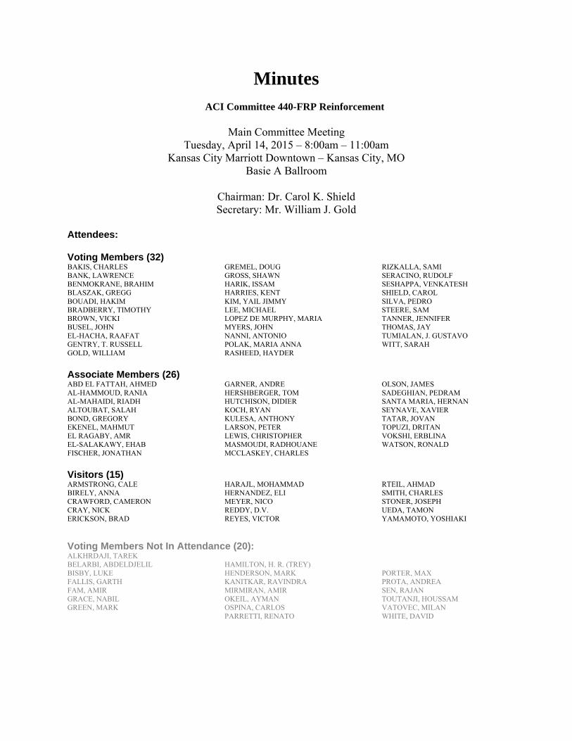
6. 440 Membership Overview – In Dr. Shield’s membership report, she indicated that we have moved a
few voting members to consulting or associate member status based on their committee participation since the last convention.
Shield then presented the status of Committee documents as follows:

5
7. Ballot Results for 440.2R (Seismic and other) – Harries gave an overview of the ballot results from
two ballots on proposed revisions to the ACI 440.2R document. One ballot included the addition of specific recommendations on seismic design; the other ballot was on other changes and additions to the document. Ballot Results for 440.2R Seismic Additions Harries first presented the comments and proposed resolution to the ballot on the addition of seismic design recommendations. Based on discussions with committee members, several negative comments received were withdrawn. Harries presented those withdrawn negatives as shown below:
No. Reviewer Item Sec # Pg
# Ln #
N/AC Comment Resolution
14 Ospina 1 13.3.2 4 125 N I strongly recommend a figure be added showing the strain distribution diagrams of an unreinforced section and an FRP-strengthened section, where all terms are defined and a distinction is made between the strains at yield and the strains at ultimate so the benefit of the FRP strengthening is fully appreciated.
Withdrawn following discussion (email 3.7.15) The seismic TG does not view the purpose of the chapter to be instructive in this way. Additionally, any ‘example’ will be necessarily limited in scope and therefore have limited utility.
16 Ospina 1 13.3.2 5 141 N For rectangular jackets, consider rounding 218 off to 220.
Withdrawn following discussion (email 3.7.15) equation comes directly from cited reference
19 Ospina 1 13.4 6 172 N The proposed language does not emphasize the need for ∑Mn in the columns to exceed ∑Mn in the beams framing into a common joint. This condition is consistent with the so-called “strong column - weak beam” design approach. How much the ∑Mn,col to ∑Mn,beam ratio should be also needs to be discussed (In ACI 318, this ratio is equal to 6/5). This requirement needs to be satisfied when strengthening RC building structures with FRP. If this requirement is not explicitly mentioned in Chapter 13 designers may well end up designing for “weak column - strong beam” scenarios, which are unacceptable for the seismic design of RC building structures.
Withdrawn following discussion and based on resolution of 22 (email 3.16.15) This issue is really beyond the scope of 440.2. The text does indicate: The flexural capacity of reinforced concrete beams and columns in expected plastic hinge regions can be enhanced using FRP, only in cases where strengthening will eliminate inelastic deformations in the strengthened region and transfer inelastic deformations to other locations in the member or the structure that are able to handle the ensuing ductility demands. The required flexural strength should be calculated in accordance with the design standard being used for rehabilitation… see resolution to comment #73 which is related to this item
140 Ospina 4 Procedure Step 2
9 106 N In the Lp calculation, revise “44.00” to read just “44”. Also, the Lp equation is presented here in inches and ksi units while in the guidelines it is presented in inches and psi units. Please pick only one format throughout, for consistency. Please check the Δp calculation. Per the info presented in step 3, the column does not seem to be a flagpole-type column.
Withdrawn following discussion (email 3.7.15) Displacement calculation no longer required in this example and has been removed
6
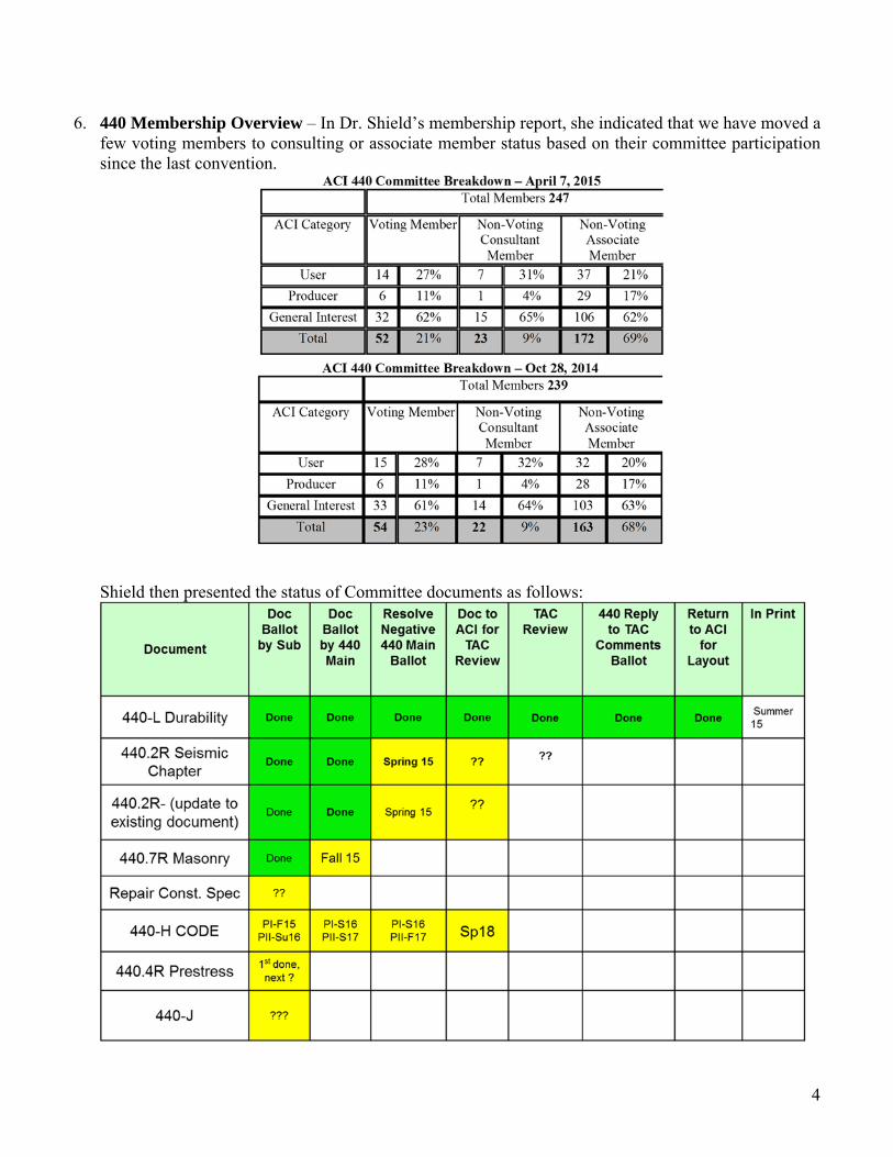
Harries then presented a series of comments received that were mainly editorial (not substantive changes to the document).
Motion #1: Harries moved to find following comments persuasive and resolve these comments as indicated in the following table:
No. Reviewer Item Sec # Pg #
Ln #
N/AC Comment
Resolution
10 Ospina 1 Intro 1 5 N Replace “…to outcomes of a seismic assessment and…” with “…to the outcome of a seismic evaluation of the structure and…”
Persuasive – revise as indicated
31 Shield 1 13.3 3 ??? N Somewhere in this section, the reader should be told that the fibers should go circumferential
Persuasive – propose revising line 88: Jacketing concrete structural members with FRP having the primary fibers oriented around the perimeter of the member provides confinement… see comments 33 and 35
11/ 113
32
Ospina/Brown
Shield
1 13.3.2 3 104
105-
108
N
N
Somewhere in this section you need to add ɸ D < ɸ
U,FRP . This requirement is shown in the examples but does not appear anywhere in Chapter 13. You need to reference the equations sequentially in the text (i.e. you need to put equation 13-3 before 13-2 or change the text
Persusasive – revise as follows: revise Eq. 13-1: ϕD = θp/Lp + ϕy,FRP ≤ ϕu,FRP revise lines 106-110 as follows: where Lp is the plastic hinge length computed using Eq. (13-3), and θp is the plastic rotation demand, which can be determined following the analytical procedures outlined in ASCE/SEI 41. In Eq. (13-1), the curvatures of the FRP confined section at steel yielding, ϕy,frp, and at ultimate capacity, ϕu,frp are is determined by Eqs. (13-2) and (13-3), respectively, and Lp is the plastic hinge length computed using Eq. (13-3). ϕy,frp = εc/(d-cy,frp) 13-2 where εc and cy are the concrete strain and depth of the neutral axis at steel yielding, respectively. ϕu,frp = εccu/cu,FRP 13-3 where εccu and cu,FRP are the concrete strain and depth of the neutral axis at ultimate capacity, respectively. Appendix E provides… Response acceptable to voter (3.7.15 email)
33 Shield 1 13.3.2 4 115 N Where it talks about discrete strips, indicate that the fiber direction in the discrete strips needs to be circumferential
Persuasive – revise as follows consistent with line 113: …discrete FRP strips having the primary fibers oriented around the perimeter of the member can be used. see comments 31 and 35
12/ 123
Ospina/Shield
1 13.3.2 4 118 N Eq. 13-3 is presented in inches and psi units but in the examples the equation is presented in inches and ksi units. Please pick only one for consistency.
Persuasive –Eq. 13.3 remains as is; example changed to psi units
34 Shield 1 13.3.2 4 122 N This figure looks bad, the text is barely readable Persuasive – revise figure with larger font and verify clarity
15 Ospina 1 13.3.2 4 130 N Revise text to read “the extreme compression fiber strain in the concrete at ultimate, εccu,…”
Persuasive – revise as indicated
17 Ospina 1 13.3.4 5 149 N Consider revising text to read “Continuous or discrete transverse FRP strips…”
Persuasive – revise as indicated
35 Shield 1 13.3.4 5 149 N Indicate the direction of the discrete strips Persuasive – revise as follows consistent with line 113 (see comment 33): …Continuous or discrete FRP strips having the primary fibers oriented around the perimeter of the member can be used… see comments 31 and 33
18 Ospina 1 13.3.4 5 149 N Please add a figure showing all the elements that participate in the definition of Eq. 13-7.
Persuasive

7
No. Reviewer Item Sec # Pg #
Ln #
N/AC Comment
Resolution
The seismic TG feels that the text is clear without an added figure; however the following clarifying revision is made: where n is the number of FRP plies, tf is the thickness per ply, D is the diameter of the section, wf is the FRP strip width, and sf is the center-to-center spacing of the FRP strips. For continuous confinement, wf/sf = 1. Response acceptable to voter (3.7.15 email)
37/ 55
Shield/Brown
1 13.4.2 7 208 N The equation number here (“using Eq 13-2)” is not correct, Eq 31-2 is about curvature, not development length.
Persuasive – Reference is to existing Eq. 13-2 which will become 14-2
20 Ospina 1 13.4 8 216 N I would prefer if Fig.13-2 shows a more realistic connection with a larger column and shallower beams. The detail, as is, represents a strong beam – weak column condition which is not to be promoted.
Persuasive. Beams were reduced in height.
21 Ospina 1 13.5 8 221 N In Eq. 13-15, what does the superscript “e” in the design shear force stand for?
Persuasive - Ve is the design shear force from ACI 318 21.5.4. It makes sense to use it in our chapter for consistency. This parameter will be added to Chapter 2. Response acceptable to voter (3.7.15 email)
38 Shield 1 13.5 8 232 N Change “The methodology..” to “A methodology…” Persuasive The sentence is removed since it refers to Appendix that has been deleted.
23/ 58/ 61/ 62/ 74/ 97 41/ 42/ 43
Ospina/Brown/Lubell/Tanner
Shield
1
13.7 9 257 N
N
Replace “Chapter 14” with “13.7 – Strengthening of Reinforced Concrete Shear Walls” Fix equation numbering problems
Persuasive – additionally, equation and figure numbering in 13.7 is incorrect and should run consecutively
24 Ospina 1 13.7 10 273 N I do not see the need to list all the variables for Fig. 14-1 in the middle of the document. Rather, the variables should be presented in the notation section.
Persuasive – we do not list variables elsewhere; delete lines 273-295 ensuring that all listed variable appear in notation section.
25 Ospina 1 13.7.2.1 11 299 N Revise to read “… the concrete compressive strain at ultimate…”
Persuasive revise as indicated
39 Shield 1 13.7.2.2 11 306 N Chang 14-2 to 13-4 (and on line 310) Persuasive –see comment 23 26
40
Ospina
Shield
1 13.7.2.2 11 308 N
N
Figure 14-2 is very hard to read. It needs to be improved. Figure is of poor quality, please replace
Persuasive figure clarity appears to be an artefact of PDF conversion; clarity will be verified and revised as required.
27 Ospina 1 Notation 13 339 N Consider adding εc, εcs, εcy, εccu, etc… in the notation.
Persuasive – all notation appearing in Chapter 13 must appear in notation
28 Ospina 1 Ch. 10 18 547 N Revise text to read “…resisting loads. These are addressed…”
Persuasive revise as indicated
30 Parretti 1 13.4.2 8 of 12
Fig. 13-2
N Assuming that the drawing is a front view of a beam-column joint, such detail cannot be realized unless we decide to cut the beam itself to install the vertical FRP reinforcement. If this is the case and we want to keep the drawing, please alert the reader as it was done on Lines 195-197. For drawing clarity, it would also be appropriate to show a plan view as well.
Persuasive The text was added to the caption to emphasise that this is an elevation view. (Cross-Section Elevation)
98/ 112
Ospina/Brown
2 Example 13.1
1 22 N Revise “θpD” to read “θp”. Equation 13-1 is defined in terms of θp not θpD. Also, revise sentence to read Revise “…must be capable of developing a plastic rotation θp = 0.022 rad. The axial load….”
Persuasive – revise as indicated; also see comment 102
99/ 116
Ospina/Nanni
2 Table 13-1
2 36 N Line numbers accidentally got merged with the last column of the table.
Persuasive – PDF Format Issue – will be corrected
100 Ospina 2 Table 13-2
3 46 N In the header, revise “Strains Limits” to read “Strain Limits”. Consider also adding the official symbols that define the different steel and concrete strains you refer to with words.
Persuasive – revise as indicated
105 Shield 2 3 48 N Change ffu and efu to ffu* and efu* Persuasive – revise as indicated

8
No. Reviewer Item Sec # Pg #
Ln #
N/AC Comment
Resolution
101 Ospina 2 Procedure Step 2
3 49 N In the Lp calculation, revise “44.00” to read just “44”. Also, the Lp equation is presented here in inches and ksi units while in the guidelines it is presented in inches and psi units. Please pick only one format throughout, for consistency.
Persuasive – see comment 12 - Eq. 13.3 remains as is; example changed to psi units
103 Ospina 2 Procedure Step 10
4 49 N I suggest you add “OK” in both cells. Persuasive – revise as indicated
102
107
Ospina
Shield
2 Procedure Step 8
4 49 N
N
In the ϕD calculation, θp should be 0.022 and not 0.025. See problem statement. On Page 1 line 22 of the example problem it says theta_p = 0.022. Here you are plugging in 0.025. Please fix one or the other
Persuasive – revised 0.025 is correct value; 0.022 is revised.
104/114
Ospina/ Brown
2 Fig. 13-2 5 55 N The figure needs to be improved so the 2 curves can be clearly seen. Also, is “ϕuD” defined in the text?
Persuasive – revise figure with clearer line types and change ϕuD to ϕD
129/
132
Shield
Brown
3 Step 2 N Change ld to l_prov. Ld means development length. What you mean is the embedment length Move the calculation for ld from Step 2 to Step 1, where the ld is first used. Also explain how ld is calculated (reference provision) as Fig. 13-3 provides no explanation.
Persuasive – revise as indicated; ld should read lprov(ided)
106 Shield 2 Step 5 N Epsilon_y is given in the problem statement (Table 13-1) as .0015. Here it shows up as 0.00152. Please be consistent (also shows up in step 7)
Persuasive – revise to 0.0015 in all locations
127 Shield 3 7 77 N Change ffu and efu to ffu* and efu* Persuasive – revise as indicated 142 Shield 4 8 N Add in the beginning text that the FRP is carbon and
that the application is for interior exposure Persuasive – revise as indicated
143 Shield 4 8 88 N It is not clear from the figure if the 1” is clear cover, cover to the center of the tie, or cover to the inside edge of the tie. Please fix
Persuasive – figure to be revised for clarity
136 Ospina 4 Table 13-6 8 91 N Revise “ln” to read “h”. The example refers to a column, not to a beam.
Persuasive – revised to “lu” for consistency with ACI 318 Response acceptable to voter (3.16.15 email)
137 Ospina 4 Table 13-6
8 91 N Line numbers accidentally got merged with the last column of the table.
Persuasive – PDF Format Issue – will be corrected
138 Ospina 4 Table 13-7
8 98 N Line numbers accidentally got merged with the last column of the table.
Persuasive – PDF Format Issue – will be corrected
141 Ospina 4 Procedure Step 3
9 106 N In the Vu equation, replace Mpr,r and Mpr,l with Mpr,top and Mpr,bot, respectively; and also replace ln with h. The example is about a column, not about a beam.
Persuasive – revise as indicated
144 Shield 4 Step2 N Put the calculations and design steps for step 2 in the same order
Persuasive – revise as indicated
145 Shield 4 Step2 N How would the reader know that g = 2” It’s not in the figure or in the problem statement
Persuasive – revise to include definition of gap provided
146 Shield 4 Step4 N I believe Av = 2*.2in^2 Persuasive – revise as indicated 147 Shield 4 Step6 N Efe = 0.75Ce(efu*) missing the * Persuasive – revise as indicated 148 Shield 4 Step6 N Add that Ce = 0.95 from table 9.1 Persuasive – revise as indicated 166 Brown 5 Ex 13-4 13-
19 Steps 1-3
N Formatting for this example is done incorrectly, to the point where it is almost impossible to follow the logic of the example. Equations should be moved to the Procedure column and appropriately documented as to where they can be found (either in this document or in appropriate sections of 318). The Calculations columns should show numerical values used in those equations to arrive at the numerical results from the equations.
Persuasive – Example to be reformatted to match others
170 Shield 5 Step2 13 N Need to add a step showing efu= Ce effu* Persuasive – revise as indicated 171 Shield 5 Step2 13 N Af = 2 sides * 3(.023in)(68in) Persuasive – revise as indicated 167 Shield 5 Step1 13 N Add Vc=2 b d rt(fc’) in the left most column Persuasive – revise as indicated 168 Shield 5 Step1 13 N Add Vsw=Avf fy d/s in the left most column Persuasive – revise as indicated 169 Shield 5 Step1 13 N Move Vn = Vc+Vs to the first column and change Vs
to Vsw Persuasive – revise as indicated
52/ 66/
Brown 1/3/4
13.3, 13.7 4-5 12
127-
E When specific sections of ACI 318 are cited, we must include the version; i.e. this should be 318-11? Would
Entire 440.2 document is being revised to ACI 318-11 (not 14). The protocol we have
9
No. Reviewer Item Sec # Pg #
Ln #
N/AC Comment
Resolution
151/
156/
157
128,
148,
324
we be better off citing 318-14 as the most current version?
adopted is to cite ACI 318 in the text and the correct version in the references. This is apparently consistent with ACI practice.
111/150/152/173
/ 115
/ 174
Brown/
Nanni
Paretti
2/3
2-5
5
Ex. 13-1
13-4
1, 5
11
19, 53, 57
121
E Correct figure and table numbers. Can’t use same numbers as were used in Chapter 13. Confusing! The numbering of all sections including figures and tables may have to be updated to reflect the inclusion of these examples in the appropriate Chapter of the guide Figure and tables numbering do not match.
Persuasive Revise as required – Examples all appear in Ch.15 which will become Ch. 16.
120 Shield 2-4 G Renumber figures and tables see comment 111 85 Shield 1 1 29-
30 AC Make one sentence (get rid of paragraph break after
“…2008a).” Persuasive Revise as indicated
83 Shield 1 1 2 AC Change “the optimum” to “effective”. I doubt we are able to find the optimum
Persuasive Revise as indicated
84 Shield 1 1 22 AC Change limited to small Persuasive Revise as indicated 50 Brown 1 13 1 29 E Check Pampanin et al reference date – 2006 in
document but 2007 in cited references Persuasive Revise occurrence in text at line 29 to 2007
86 Shield 1 13.1 2 58 AC Add “the” between of and ASCE Persuasive Revise as indicated 87 Shield 1 13.2 3 79-
80 AC Replace “of the FRP materials which comprise the
seismic strengthening solution.” With “of the FRP retrofit.”
Persuasive Revise as indicated Persuasive Revised with a slight modification
51/ 71
Brown/ Kim (ACI
369)
1 13.3 3 97 E Can not find Kim et al 2011 in cited references – please add
Persuasive – reference added
96 Tanner 1 3 97 E Add a period after al in Kim et al. 2011. Persuasive Revise as indicated 69 Gold 1 13.3.3 5 141 E The structure of Equation 13-5 is odd. Suggest
reorganizing. Persuasive Revise Eq as four individual lines: circular columns: ntf = 145D/Ef (in. and ksi) circular columns: ntf = 1000D/Ef (mm and MPa) rectangular columns: ntf = 218D/Ef (in. and ksi) rectangular columns: ntf = 1500D/Ef (mm and MPa)
45 Bakis 1 13.3.2 5 147 E Use an actual lower case Greek psi on the right side of eq. 13-6 (as is used in the surrounding text).
Persuasive Revise as indicated
70 Gold 1 13.3.4 6 158 E Add a reference to Equation 12-8 instead of stating that D is the diagonal length of rectangular sections.
Persuasive Revise as follows: D is the diameter of a circular section or the diagonal length of a rectangular sections (Eq. 12-8),…
91 Shield 1 13.4.2 7 AC Sometimes we say “longitudinal FRP” sometimes we say “flexural FRP” pick on and stick to it.
Persuasive – “flexural FRP” adopted consistently.
88 Shield 1 13.4 7 184-
185
AC Delete “bar hooks and bends,” it is redundant with “development length”
Persuasive Revise as indicated
54 Brown 1 13.4 7 198 E Delete “the flexural FRP reinforcement” the first time it occurs in this sentence to improve readability.
Persuasive Revise as indicated
90 Shield 1 13.4.2 7 213 AC Add “longitudinal” in front of “FRP so as to “ Persuasive Revise as indicated 44 Bakis 1 13.3.2 3, 4 106
, 109
, 131
E Use an actual lower case Greek phi on the left side of eqs. 13-1, 13-2, and 13-4 (as is used in the surrounding text).
Persuasive Revise as indicated
56 Brown 1 Fig 13-2 8 217 E The arrows used to locate the Transverse FRP wraps actually point to longitudinal FRP. Please adjust.
Persuasive Revise figure accordingly
93 Shield 1 13.5 8 237 AC Change “using Eq. 13-16.” To “using Eq. (13-16).” Persuasive Revise as indicated 50/ 57
Brown 1 13.6 9 243 &
247
E Check Pampanin et al reference date – 2006 in document but 2007 in cited references
Persuasive Revise occurrence in text at line 29 to 2007
46 Bakis 1 13.7.2 10 291 E Fix blue font, italicize Tst Persuasive Revise as indicated 47 Bakis 1 13.7.2 11 295 E Fix blue font Persuasive Revise as indicated 94 Shield 1 13.7.2.2 11 303 AC Change “flexural” to “flexurally” (twice) Persuasive Revise as indicated
10
No. Reviewer Item Sec # Pg #
Ln #
N/AC Comment
Resolution
95 Shield 1 13.7.2.2 11 304 AC Change “across” to “through” Persuasive Revise as indicated 48 Bakis 1 13.7.3 12 324 E Italicize letters used as math symbols Persuasive Revise as indicated 63 Brown 1 13.7 12 328 E Delete “severe” in front of “seismic event” as
redundant. We already state “severe cracking” earlier in the sentence.
Persuasive Revise as indicated
81 Nanni 1 Ch 13 12 336 E Eliminate “,” after “Binici” Persuasive Revise as indicated 49 Bakis 1 13 341
-77 E Italicize letters used as math symbols. Check upper
vs. lower case Greek psi on line 375-77. Persuasive Revise as indicated
65 Brown 1 Notation 13 372 E Correct typo in symbol, should be frp not ftp Persuasive Revise as indicated 67 Brown 1 References 15 466
-467
E Correct citation to include date of publication Persuasive add date of workshop: April 26-27, 2004
68 Brown 1 References 16 492-
493
E Correct citation to show date of publication consistent with other references.
Persuasive citation placed in correct format
82 Parretti 1 13.4.2 7 of 12
198-
199
E Rewrite the sentence as follows: “Away from the plastic hinge region, use transverse FRP U-wrap strips to provide anchorage to the FRP flexural reinforcement”.
Persuasive – revise as indicated; existing sentence is grammatically incorrect in any event.
118 Shield 2 1 3 AC Change “of FRP to” to “of a FRP retrofit to” Persuasive Revise as indicated 119 Shield 2 1 6 AC Change (2) to (2) ties do not project into core, under
seismic loads, the ties may open once the cover concrete…
Persuasive Revise as indicated
121 Shield 2 1 22 AC Change “and the axial” to “. The axial” Persuasive Revise as indicated 108 Bakis 2 13.1 2 33 E Please use a blank space between a numeral and its
unit (Fig. 13-1). Persuasive Revise as indicated
122 Shield 2 3 46 AC I believe Table 31-2 is directly from ASCE 41. If show, it should say that in the table title
Persuasive reference to ASCE 41 included in caption.
109 Bakis 2 13.1 4 50 E In the example table, Steps 7-10, fix the incorrect Greek phi symbol so that it matches the “majority opinion” in the document.
Persuasive Revise as indicated
110 Bakis 2 13.1 5 56 E Use “kip” not “kips” for units on the vertical axis. (kips appears randomly throughout the document)
Persuasive Revise as indicated
117 Parretti 2 13.1 4 of 19
Table
E Last row of the table (Procedure – Calculation in US units – Calculation in SI unist): the sentence “Confining jacket should extend” need to be completed.
Persuasive – sentence revised as follows: Confining jacket should extend at least 18 in. (305 mm) beyond the joint interface.
124 Shield 2 Step 3 AC Please swap order of ka and kb in columns 2 and 3 to be consistent with order in column 1
Persuasive Revise as indicated
125 Shield 2 Step 4 AC Reference where psi_f comes from Persuasive Revise Section 2.1 Notation as follows: Ψf = 0.95 for shear fully wrapped sections Indicate Section 2.1 in step 4
126 Shield 2 Step 7 AC Eq 13-2 says phi_y=epsilon_c/c_y. What you are using here is phi_y=epsilon_s/(d-c_y), which isn’t exactly the same, but comes from the same principal. I suggest adding the second part to Eq. 13-2
Persuasive –suggest revise as indicated Prefer to modify the Eq. 13-2 to:
,,
130 Bakis 3 13.2 6 74 E Please use a blank space between a numeral and its unit (Fig. 13-3).
Persuasive Revise as indicated
133 Brown 3 Ex. 13-2 7 Step 2
E Correct equation in Procedure column. Eq. 13-6 does not include a λ term.
Persuasive Revise as indicated
134 Brown 3 Ex. 13-2 7 Step 3
E Correct typo in Eq. 13-5. Should be Ef not Ej Persuasive Revise as indicated
154 Brown 4 Ex. 13-3 8 Table
13-7
E Define D Persuasive D is not required in this example; revised accordingly
153 Brown 4 Ex. 13-3 8 Table
13-6
E Provide column height ln as 10 ft rather than inches, because it is used in feet in Step 3 (also correct Step 3 to be 10 rather than 120/12). Also identify “Applied Axial Load” to be Pu. Actually, does this value have to be provided as it is not used (at least not directly) in this example.
Persuasive Revise as indicated The axial load is used for the moment curvature calculations
158 Shield 4 8 82 AC Add “the” after “illustrates Persuasive Revise as indicated

11
No. Reviewer Item Sec # Pg #
Ln #
N/AC Comment
Resolution
149 Bakis 4 13.3 8 88 E Please use a blank space between a numeral and its unit (Fig. 13-4). This problem appears randomly throughout the document.
Persuasive Revise as indicated
159 Shield 4 Step 1 9 AC Can we at least add the plot of the Moment curvature curve
Persuasive The probable moment capacity results from the section at the ends of the member and not at the section where the shear capacity is being evaluated. Steps 1 and 2 were removed and the information pertaining to the probable moment capacity and ductility were changed to the problem statement. Step 7 compares the shear capacity and design demands .
155 Brown 4 Ex. 13-3 9 Step 2
E In the Procedure column, explain where equations for μΔ, Δy, FRP, Leff, and Δp come from. Move equations for Lp to the top of the section to line up with the corresponding values in the Calculations columns and provide the Equation number for Lp.
Persuasive Revise as indicated
160 Shield 4 Step 1 AC Mover the value for the yield curvature and the ultimate curvature up from step 2 to step 1. All three of these values are coming from the moment-curvature relationship
Persuasive Revise as indicated
161 Shield 4 Step2 AC Add, frp to the subscript on Delta_p (in all three columns)
Persuasive Revise as indicated
162 Shield 4 Step 2 AC Add that the equation for LP is Eq 13-3 Persuasive Revise as indicated 163 Shield 4 Step2 AC How would one know to use Ln/2 as Leff? Can the
rationale behind this be clarified? Persuasive provide reference to section in Chapter 13
135 Shield 3 Step3 AC Change tj to n*tf to be consistent with what is in the text
Persuasive Revise as indicated
164 Shield 4 Step4 AC Change D’ to d in Vs equation Persuasive Revise as indicated 165 Shield 4 Step7 AC Add reference to Eq 11-6 after Afv=2tf*wf Persuasive Revise as indicated 172 Bakis 5 13.4 E Check throughout. “kips” should be “kip”. “KN” should
be “kN”. “k” should be “kip”. Psi should be lower case. Use a space between a numeral and its unit.
Persuasive Revise all as indicated – check entire document
175 Shield 5 12 1 AC Add “and Demands” to the table title (it has more than just As-Built properties in it)
Persuasive Revise all as indicated
176 Shield 5 Step1 13 AC Move equations in terms of letters to the left most column (Mn, d, and a)
Persuasive - see comments 166-169
Motion #1 was seconded by Witt. Shield opened the floor for discussion on the motion. There was no discussion. Upon hearing the motion, the motion was put to a vote. 28 members voted “affirmative”, 0 members voted “no”, and 0 members abstained. The motion carries. ---------
12
Harries then presented a second set of comments on the seismic additions that required more substantive changes or clarification in the document. Motion #2: Harries moved to find following comments persuasive and resolve these comments as indicated in the following table:
No. Reviewer Item Sec # Pg #
Ln #
N/AC Comment
Resolution
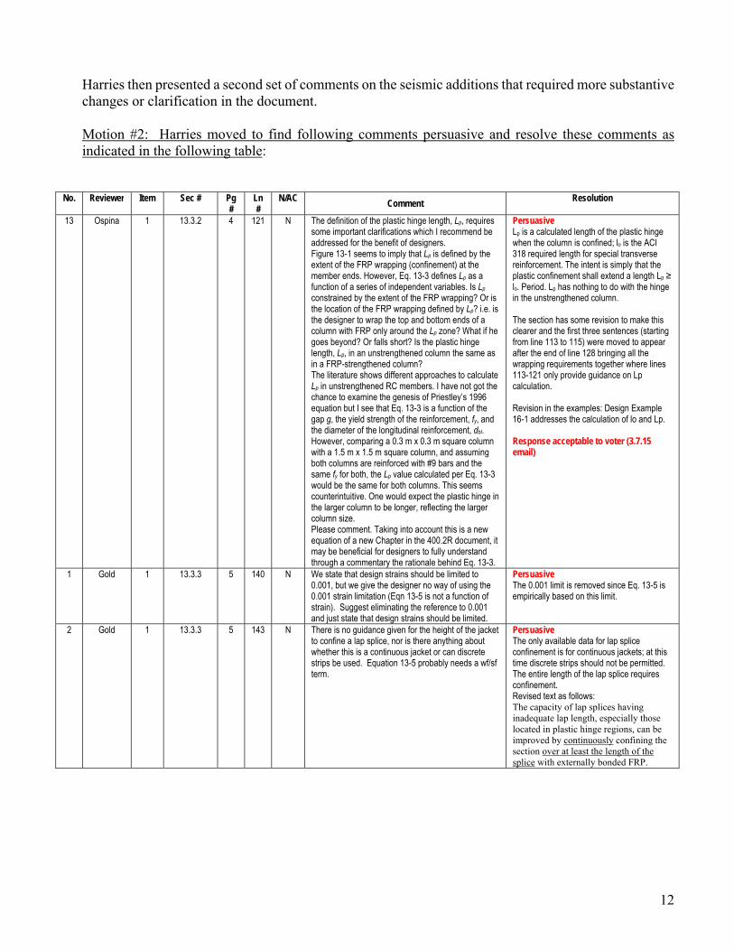
13 Ospina 1 13.3.2 4 121 N The definition of the plastic hinge length, Lp, requires some important clarifications which I recommend be addressed for the benefit of designers. Figure 13-1 seems to imply that Lp is defined by the extent of the FRP wrapping (confinement) at the member ends. However, Eq. 13-3 defines Lp as a function of a series of independent variables. Is Lp constrained by the extent of the FRP wrapping? Or is the location of the FRP wrapping defined by Lp? i.e. is the designer to wrap the top and bottom ends of a column with FRP only around the Lp zone? What if he goes beyond? Or falls short? Is the plastic hinge length, Lp, in an unstrengthened column the same as in a FRP-strengthened column? The literature shows different approaches to calculate Lp in unstrengthened RC members. I have not got the chance to examine the genesis of Priestley’s 1996 equation but I see that Eq. 13-3 is a function of the gap g, the yield strength of the reinforcement, fy, and the diameter of the longitudinal reinforcement, dbl. However, comparing a 0.3 m x 0.3 m square column with a 1.5 m x 1.5 m square column, and assuming both columns are reinforced with #9 bars and the same fy for both, the Lp value calculated per Eq. 13-3 would be the same for both columns. This seems counterintuitive. One would expect the plastic hinge in the larger column to be longer, reflecting the larger column size. Please comment. Taking into account this is a new equation of a new Chapter in the 400.2R document, it may be beneficial for designers to fully understand through a commentary the rationale behind Eq. 13-3.
Persuasive Lp is a calculated length of the plastic hinge when the column is confined; lo is the ACI 318 required length for special transverse reinforcement. The intent is simply that the plastic confinement shall extend a length Lp ≥ lo. Period. Lp has nothing to do with the hinge in the unstrengthened column. The section has some revision to make this clearer and the first three sentences (starting from line 113 to 115) were moved to appear after the end of line 128 bringing all the wrapping requirements together where lines 113-121 only provide guidance on Lp calculation. Revision in the examples: Design Example 16-1 addresses the calculation of lo and Lp. Response acceptable to voter (3.7.15 email)
1 Gold 1 13.3.3 5 140 N We state that design strains should be limited to 0.001, but we give the designer no way of using the 0.001 strain limitation (Eqn 13-5 is not a function of strain). Suggest eliminating the reference to 0.001 and just state that design strains should be limited.
Persuasive The 0.001 limit is removed since Eq. 13-5 is empirically based on this limit.
2 Gold 1 13.3.3 5 143 N There is no guidance given for the height of the jacket to confine a lap splice, nor is there anything about whether this is a continuous jacket or can discrete strips be used. Equation 13-5 probably needs a wf/sf term.
Persuasive The only available data for lap splice confinement is for continuous jackets; at this time discrete strips should not be permitted. The entire length of the lap splice requires confinement. Revised text as follows: The capacity of lap splices having inadequate lap length, especially those located in plastic hinge regions, can be improved by continuously confining the section over at least the length of the splice with externally bonded FRP.

13
No. Reviewer Item Sec # Pg #
Ln #
N/AC Comment
Resolution
73 Lubell 1 13.4 6 180 E This sentence does not make it obvious that the required Mu may need to be based on the probable moment of an adjacent section if the strengthening is intended to relocate the plastic hinge to the adjacent section. In comparison, this is explicitly described in Section 13.5.1 of this document. A similar level of detail should be used.
Persuasive – relates to comment 19 revise second paragraph of 13.4 as follows: The flexural capacity of reinforced concrete beams and columns in plastic hinge regions can be enhanced using the design methodology presented in Chapter 10. The flexural strength in the plastic hinge region, φMn, should satisfy the requirement of Eq. (13 13):
[EQ 13-13 remains unchanged] where Mu is the ultimate moment demand in the plastic hinge region resulting from combined gravity and lateral load analyses seismic demands. … Response acceptable to voter (2.28.15 email) and Seismic TG
128 Shield 3 Step1 N The development length calculations are not correct. Cb is the smaller of ½ the C-o-c spacing and the distance from the surface to the center of the bar. The problem correctly shows that the distance to the center of the bar is the smaller. If that is the where Cb comes from, then the potential plane of splitting DOES NOT go through all the bars. It only goes through a single bar, so Ktr is not calculated correctly. In Ktr, n=1, Atr = 0.11
Persuasive – revise as follows s = 12; n = 1; Atr = 0.11 making Ktr = 0.37 (cb + Ktr)/db = 2.24 fs = 37,779 psi remainder of example is correct
Motion #2 was seconded by Witt. Shield opened the floor for discussion on the motion. There was no discussion. Upon hearing the motion, the motion was put to a vote. 28 members voted “affirmative”, 0 members voted “no”, and 0 members abstained. The motion carries. --------- Harries then presented a third set of comments on the seismic additions that needed clarification in the document. Motion #3: Harries moved to find following comments persuasive and resolve these comments as indicated in the following table:
No. Reviewer Item Sec # Pg #
Ln #
N/AC Comment
Resolution
36/ 89
Shield 1 13.4.2 7 193-
194 &
200-
201
N/AC The statement “The type, amount, and spacing of the anchorage reinforcement should be determined experimentally.” Seems to imply that for EVERY project, one has to run a bunch of experiments. I hope that isn’t what we mean.
Persuasive - revise as follows wording comes from approved revisions to Section 1.2: Alternatively, the flexural FRP reinforcement could be anchored over the its entire length of the flexural FRP. The type amount and spacing of the anchorage reinforcement should be determined experimentally. Such detailing provides in order to provide higher resistance against debonding of the flexural FRP reinforcement. Because no anchorage design guidelines are currently available, the performance of any anchorage system should be substantiated through representative physical testing.

14
No. Reviewer Item Sec # Pg #
Ln #
N/AC Comment
Resolution
29 Parretti 1 13.4.2 7 of 12
197 N Add at the end of the sentence: As an alternative to localized cutting of the slab, use of FRP end-anchors to prevent FRP delamination similar to what it is shown in Figure 1 could be implemented, if testing has proved the effectiveness.
Figure 1 – Alternative anchorage system to avoid
localized cutting of the slab
Persuasive – The TG agrees that cutting the slab may not be practical or feasible. For this reason, the document provides language in the previous section that allows the use of anchorage of the flexural FRP. Also, as part of the ballot for revisions to ACI 440.2R (Ballot Item 4) a new figure is proposed which shows the anchors suggested by Parretti. The TG believes that the document as it stands, with the proposed addition of the anchorage discussion and the new figure, fulfils the intent of Parretti’s comment and that the suggested change is not required. per 2.24.15 email: My negative vote on item #29 may be considered resolved, provided that Figure X of Item 4 of the currently open ballot on 440.2 (ending on 2/27/15) will be included in the document.
75 Lubell 1 14 9 257 E Text in this section applies to so-called flexural walls with higher height/length ratios. It will not apply to the analysis and design methods applicable to so-called squat shear walls where the height/length ratio is less than about 2. This limitation should be described in the opening part of Section 14 or an additional section for squat shear walls added.
Persuasive: The comment is well taken. ASCE 41 defines squat walls as having an aspect ratio < 1.5. ACI 318 Section R11.9.9 discusses hw/lw issues and some key points are: 1) horizontal shear reinforcement starts to be less effective as wall becomes shorter and vertical reinforcement becomes more effective; 2) at hw/lw > 2.5 – minimum vertical reinforcement is required; 3) for hw/lw < 0.5 – vertical reinforcement equal to horizontal reinforcement. However, in Eqn 11-29 of the seismic document, only horizontal reinforcement is used to compute shear strength with no provision to only rely on vertical reinforcement. The following sentence is added at line 260 to address the comment: “For low walls, with height-to-length ratios < 1.5, vertical FRP strips may also be required (ACI 318, Section 11.9.9)”. The rationale is that since the current strength provisions are based on effective depth, which is the lesser of lw or hw, the seismic document should provide adequate retrofit strength values. The designer can decide if vertical strips are also necessary.
76 Lubell 1 13.7.1 9 264 E “…corresponding to the nominal flexural strength” will not be sufficient if this is in the plastic hinge region, where probable flexural strength is normally appropriate. Similar for sentence at line 266 discussing shear retrofit. Suggest to reorder the paragraph and alter as follows: “The shear strength of walls reinforced with FRP for flexure should be evaluated and compared to the shear strength corresponding to the nominal flexural strength of the retrofitted structure promote flexural failure rather than a brittle shear failure. Where required, additional shear strength should be added to promote flexural failure rather than a brittle shear failure. Similarly, a shear retrofit should achieve greater shear capacity than the shear corresponding to the nominal flexural capacity of the wall. However, where required based on the design assumptions of plastic hinge regions, additional shear strength should be added to achieve a shear strength corresponding to the probable flexural capacities of the hinges.”
Persuasive: The change suggested to combine the sentences on lines 263 to 265 has been implemented as proposed. ASCE 41 Section 6.7.2.4.1 requires that the nominal flexural strength of a shear wall be used to determine the maximum shear force in the wall (even at the base of cantilever walls) and does not explicitly make a reference to plastic hinge zones. For this reason, the last sentence of the comment is not incorporated. Response acceptable to voter (2.23.15 email)

15
No. Reviewer Item Sec # Pg #
Ln #
N/AC Comment
Resolution
78 Lubell 1 13.7.2.2 11 303 E This section does not discuss if any specific procedures are needed for one-sided retrofits, whereas that is explicitly discussed for shear retrofits in Section 13.7.3. Guidance should be given.
Persuasive add text at beginning of 13.7.2: “FRP reinforcement for flexural strengthening of walls may be provided on one or both sides of the wall.”
64 Brown 1 13.7 12 330-
331
E Delete sentence about strength reduction factor φ per the chosen design standard as there is no mention of φ in Eq. 14-6.
Persuasive Eq. 13-20 was inserted to clarify the phi factor. This is also consistent with the design example.
Motion #3 was seconded by Witt. Shield opened the floor for discussion on the motion. There was no discussion. Upon hearing the motion, the motion was put to a vote. 26 members voted “affirmative”, 0 members voted “no”, and 0 members abstained. The motion carries. --------- Harries then presented the final set of comments on the seismic additions that are related to the overall design philosophy and inclusion of ASCE 41. Motion #4: Harries moved to find following comments persuasive and resolve these comments as indicated in the following table:
No. Reviewer Item Sec # Pg #
Ln #
N/AC Comment Resolution
22 Ospina 1 13.5.2 8 237 N Equation 13-16 alone does not ensure safety. In fact, Chapter 13 is missing language on the need to adopt capacity protection principles for FRP strengthening of RC building components or structures. The concept is briefly brought up in the shear wall design section. It should be brought up much earlier, in the background section of Chapter 13 or even at the very beginning. Capacity protection is a fundamental concept in seismic design of RC structures. The fact ASCE/SEI 41 or ACI 318 explicitly call for its implementation does not mean ACI 440.2R should not explicitly mandate it. I propose the following sentence be added in the text: “Strengthening of RC building components or structures with FRP shall follow capacity protection principles. In capacity design (Hollings 1968, Park and Paulay 1976) a desirable mechanism of inelastic response under seismic action is ensured by providing a strength hierarchy (strong column – weak beam; shear strength > flexural strength).” Add the following references: Hollings, J., 1968. “Reinforced Concrete Seismic Design”. Bulletin of the New Zealand Society for Earthquake Engineering. 2(3) 217-250. Park, R. and Paulay, T., 1976. “Reinforced Concrete Structures,” Wiley, 800 pp.
Persuasive An issue for ACI 369 and beyond scope of 440.2 However… the proposed sentence was added as follows in the second to last paragraph of 13.0: This chapter presents design guidelines for the seismic strengthening of reinforced concrete elements using externally bonded FRP composites. The design guidelines described herein are intended to be used in conjunction with the fundamental concepts, analysis procedures, design philosophy, seismic rehabilitation objectives, and acceptance criteria set forth in documents such as ASCE/SEI 41 and ACI 369. Strengthening of RC building components or structures with FRP shall follow capacity protection principles. In capacity design (Hollings 1968, Park and Paulay 1976) a desirable mechanism of inelastic response under seismic action is ensured by providing a strength hierarchy (strong column – weak beam; shear strength > flexural strength). Application of these design guidelines for the seismic rehabilitation of non-building structures such as bridges, wharves, silos, and nuclear facilities warrant additional consideration. References also be added as indicated
16
No. Reviewer Item Sec # Pg #
Ln #
N/AC Comment
Resolution
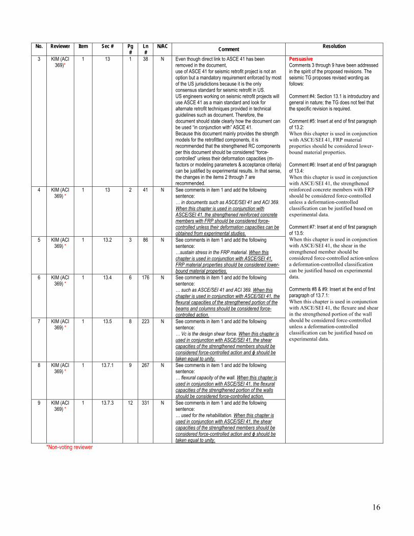
3 KIM (ACI 369)*
1 13 1 38 N Even though direct link to ASCE 41 has been removed in the document, use of ASCE 41 for seismic retrofit project is not an option but a mandatory requirement enforced by most of the US jurisdictions because it is the only consensus standard for seismic retrofit in US. US engineers working on seismic retrofit projects will use ASCE 41 as a main standard and look for alternate retrofit techniques provided in technical guidelines such as document. Therefore, the document should state clearly how the document can be used “in conjunction with” ASCE 41. Because this document mainly provides the strength models for the retrofitted components, it is recommended that the strengthened RC components per this document should be considered “force-controlled” unless their deformation capacities (m-factors or modeling parameters & acceptance criteria) can be justified by experimental results. In that sense, the changes in the items 2 through 7 are recommended.
Persuasive Comments 3 through 9 have been addressed in the spirit of the proposed revisions. The seismic TG proposes revised wording as follows: Comment #4: Section 13.1 is introductory and general in nature; the TG does not feel that the specific revision is required. Comment #5: Insert at end of first paragraph of 13.2: When this chapter is used in conjunction with ASCE/SEI 41, FRP material properties should be considered lower-bound material properties. Comment #6: Insert at end of first paragraph of 13.4: When this chapter is used in conjunction with ASCE/SEI 41, the strengthened reinforced concrete members with FRP should be considered force-controlled unless a deformation-controlled classification can be justified based on experimental data. Comment #7: Insert at end of first paragraph of 13.5: When this chapter is used in conjunction with ASCE/SEI 41, the shear in the strengthened member should be considered force-controlled action unless a deformation-controlled classification can be justified based on experimental data. Comments #8 & #9: Insert at the end of first paragraph of 13.7.1: When this chapter is used in conjunction with ASCE/SEI 41, the flexure and shear in the strengthened portion of the wall should be considered force-controlled unless a deformation-controlled classification can be justified based on experimental data.
4 KIM (ACI 369) *
1 13 2 41 N See comments in item 1 and add the following sentence: … in documents such as ASCE/SEI 41 and ACI 369. When this chapter is used in conjunction with ASCE/SEI 41, the strengthened reinforced concrete members with FRP should be considered force-controlled unless their deformation capacities can be obtained from experimental studies.
5 KIM (ACI 369) *
1 13.2 3 86 N See comments in item 1 and add the following sentence: …sustain stress in the FRP material. When this chapter is used in conjunction with ASCE/SEI 41, FRP material properties should be considered lower-bound material properties.
6 KIM (ACI 369) *
1 13.4 6 176 N See comments in item 1 and add the following sentence: … such as ASCE/SEI 41 and ACI 369. When this chapter is used in conjunction with ASCE/SEI 41, the flexural capacities of the strengthened portion of the beams and columns should be considered force-controlled action.
7 KIM (ACI 369) *
1 13.5 8 223 N See comments in item 1 and add the following sentence: … Vc is the design shear force. When this chapter is used in conjunction with ASCE/SEI 41, the shear capacities of the strengthened members should be considered force-controlled action and ɸ should be taken equal to unity.
8 KIM (ACI 369) *
1 13.7.1 9 267 N See comments in item 1 and add the following sentence: … flexural capacity of the wall. When this chapter is used in conjunction with ASCE/SEI 41, the flexural capacities of the strengthened portion of the walls should be considered force-controlled action.
9 KIM (ACI 369) *
1 13.7.3 12 331 N See comments in item 1 and add the following sentence: … used for the rehabilitation. When this chapter is used in conjunction with ASCE/SEI 41, the shear capacities of the strengthened members should be considered force-controlled action and ɸ should be taken equal to unity.
*Non-voting reviewer

17
Motion #4 was seconded by Witt. Shield amended the motion to indicate that the reviewer Kim is a non-voting reviewer of the document. Shield opened the floor for discussion on the motion. There was no discussion. Upon hearing the motion, the motion was put to a vote. 28 members voted “affirmative”, 0 members voted “no”, and 0 members abstained. The motion carries. --------- Shield indicated that this is a significant milestone in getting seismic design recommendations approved by the committee. The committee applauded the work of the subcommittee and task group in bringing this document to this stage. Ballot Results for 440.2R Non-Seismic Changes Shield then indicated that Harries would continue to present the comments received and proposed resolution to the other portions of the ACI 440.2R document. She further indicated that we are pulling one ballot item (Item #5) on serviceability based on comments received. She expressed that this is still an important revision to the document and hopes that the Task Group on serviceability will continue its work on this portion of the document. Harries then presented the comments received from the ballot on the other changes to the ACI 440.2R document. Based on discussions with committee members, several negative comments received on this ballot were withdrawn. Harries presented those withdrawn negatives as shown below:
No. Reviewer Item Pg
# Ln #
N/AC Comment Resolution
2 Hibben* 1 27 47 N This change removes the sample conditioning requirements of ACI 440.3R and could have a significant impact on results (especially Tg). Recommend adding after “…D7565.”: “Specimens must be conditioned per Method A of ASTM D618 prior to testing.” On a side note: I see problems with taking a sample directly from the field and running Tg. As mentioned in another comment the Tg of an epoxy follows the cure temperature – if the repair is being performed at a low temperature of 50°F (10°C) the Tg of an acceptable product will be 20°F lower than had it been cured at standard temperature.
These are issues for the material specification Withdrawn per discussion 4.12.15 .
3 Blaszak 1 45 28 N Can we include the requirement that effective strain of FRP exceed yield strain of steel stirrups?
Eq 11-6 places εfe = 0.004 which is greater than the yield strain of the conventional mild steel. Additionally, the stirrups will have an initial strain, and thus may be yielding while the FRP strain remains considerably lower than this limit. My understanding of this comment is to ensure that the Vs is correctly calculated using fy. Withdrawn per discussion 4.12.15; this item will be taken up as new business along with consideration of NCHRP 678 comments (#119-120)
47 Bouadi 2 N Remove the entire section 1.1.1. on Sustainability. Statements made in this section are not supported by any reference or study. For example the following statements may not be true:
“.., as they [FRP] are more durable than conventional materials”. Similarly
“… less energy-intensive option than a cementitious…”
Withdrawn per email 4.4.15 Committee was asked to address sustainability. While we agree that many statements are uncited, we feel the intent is correct and discussion sufficiently general. This is why we placed this section in Chapter 1 – to allow generalisation.

18
No. Reviewer Item Pg #
Ln #
N/AC Comment
Resolution
59 Bouadi 3 N Change “Because of the degradation of most FRP materials at high temperature” to “Because of the degradation of all FRP materials at temperatures exceeding Glass Transition Temperature, Tg”
Propose deleting word “most”; does not change meaning without unnecessary specificity. The statement is true with “most” however; could we not design a system that is resistant to high heat (basalt)?
61 Bouadi 3 N Change “in most cases, the structural member…” to “in all case, the structural member…”
Disagree, this is a conditional statement (Bisby agrees)
68 Hibben* 3 7 20 N The transition temperature of the wet system is quite important but there should be some test protocol associated with this. I recommend this be removed until a test protocol can be identified.
Withdrawn per discussion 4.12.15 Issue to be taken up as New Business in Tg TG
82 Bradberry 4 34 38-42
N Add to list of anchorage systems the anchors reported in Shear Strengthening of Reinforced and Prestressed Concrete Beams Using Carbon Fiber Reinforced Polymer (CFRP) Sheets and Anchors (Y Kim, K Quinn, N Satrom, J Garcia, W Sun, WM Ghannoum, JO Jirsa 2012) http://www.utexas.edu/research/ctr/pdf_reports/0_6306_1.pdf Rationale: The anchors tested were shown to be very effective and should be referenced in the committee’s report.
Negative WITHDRAWN per email 3.30.15 Cited report discusses what we have termed ‘fiber anchors’ which are included in the list of anchorage details. Guidance on their design will be taken as new business in 440F – a task group is already assembled (Scott Smith et al.).
83 Bouadi 4 N Section 10.1.1 paragraph 6 and the first part of section 13.1.1 second paragraph – The proposed text is too broad and gives the impression that adding any type of anchorage system will automatically prevent debonding and allows the FRP to reach rupture strain.
Withdrawn per discussion 4.12.15
119 Belarbi 7 N NCHRP Report 678 along with its Appendix A provides a comprehensive study on this topic with a more refined and calibrated design equations that is not captured in this document. AASHTO is now using and I think ACI 440 should make an effort to include some of those findings or justify the reasons of exclusion. The NCHRP study included every experimental test in the open literature up to 2009 and the new shear design equations were partly as a result of the at comprehensive study.
Withdrawn based on discussion 4.12.15 The ballot item addresses the inclusion of circular sections in the shear strengthening chapter. The NCHRP report does not address circular sections (since it focuses on girders). A negative on the shear provisions of 440.2 in general should be made in Item 1. 440F will take up review of shear equations and NCHRP 678 as new business.
120 Okeil 7 44-47
Incl.
N This is a follow-up to the 440-main ballot on ‘Seismic additions to 440.2R’. The literature has a lot more recent work than that used in developing shear strengthening provisions in 440.2R. I believe that it needs to be revisited in light of these efforts including major ones such as NCHRP Project 12-75 (Report 678 - Belarbi et al. 2011). The shear model proposed in this work was based on a far more complete database of experimentally tested beams (over 500). Furthermore, recommendations from this project have been adopted by AASHTO for bridges.
Withdrawn per email 4.12.15 The ballot item addresses the inclusion of circular sections in the shear strengthening chapter. The NCHRP report does not address circular sections (since it focuses on girders). A negative on the shear provisions of 440.2 in general should be made in Item 1. 440F will take up review of shear equations NCHRP 678 as new business.
19
No. Reviewer Item Pg #
Ln #
N/AC Comment
Resolution
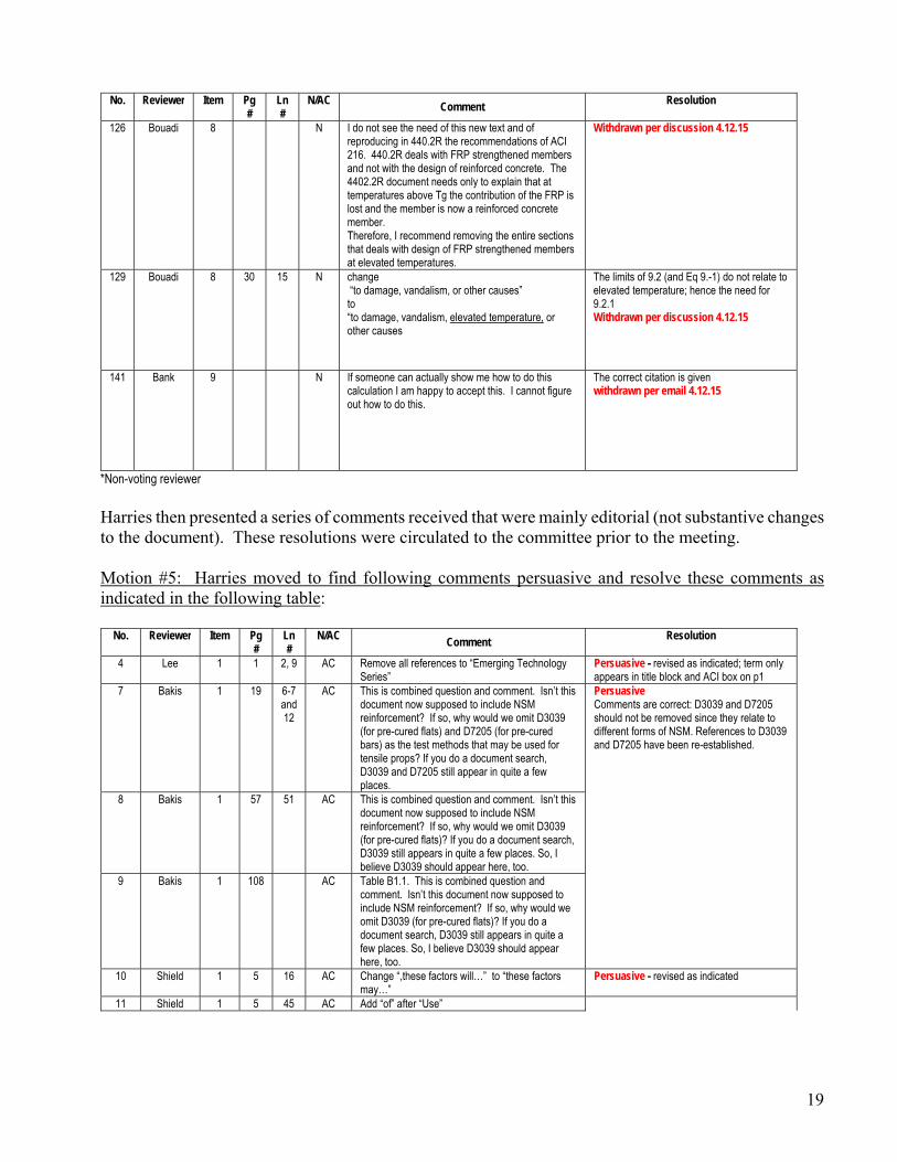
126 Bouadi 8 N I do not see the need of this new text and of reproducing in 440.2R the recommendations of ACI 216. 440.2R deals with FRP strengthened members and not with the design of reinforced concrete. The 4402.2R document needs only to explain that at temperatures above Tg the contribution of the FRP is lost and the member is now a reinforced concrete member. Therefore, I recommend removing the entire sections that deals with design of FRP strengthened members at elevated temperatures.
Withdrawn per discussion 4.12.15
129 Bouadi 8 30 15 N change “to damage, vandalism, or other causes” to “to damage, vandalism, elevated temperature, or other causes
The limits of 9.2 (and Eq 9.-1) do not relate to elevated temperature; hence the need for 9.2.1 Withdrawn per discussion 4.12.15
141 Bank 9 N If someone can actually show me how to do this calculation I am happy to accept this. I cannot figure out how to do this.
The correct citation is given withdrawn per email 4.12.15
*Non-voting reviewer
Harries then presented a series of comments received that were mainly editorial (not substantive changes to the document). These resolutions were circulated to the committee prior to the meeting.
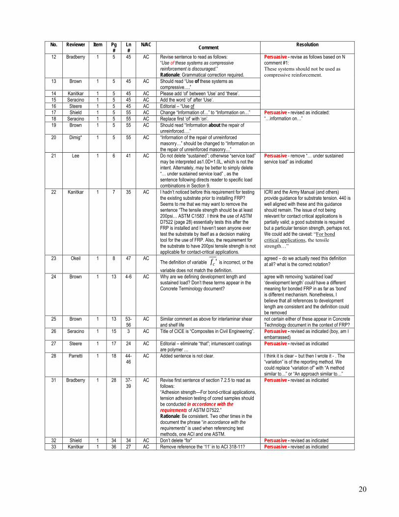
Motion #5: Harries moved to find following comments persuasive and resolve these comments as indicated in the following table:
No. Reviewer Item Pg #
Ln #
N/AC Comment
Resolution
4 Lee 1 1 2, 9 AC Remove all references to “Emerging Technology Series”
Persuasive - revised as indicated; term only appears in title block and ACI box on p1
7 Bakis 1 19 6-7 and 12
AC This is combined question and comment. Isn’t this document now supposed to include NSM reinforcement? If so, why would we omit D3039 (for pre-cured flats) and D7205 (for pre-cured bars) as the test methods that may be used for tensile props? If you do a document search, D3039 and D7205 still appear in quite a few places.
Persuasive Comments are correct: D3039 and D7205 should not be removed since they relate to different forms of NSM. References to D3039 and D7205 have been re-established.
8 Bakis 1 57 51 AC This is combined question and comment. Isn’t this document now supposed to include NSM reinforcement? If so, why would we omit D3039 (for pre-cured flats)? If you do a document search, D3039 still appears in quite a few places. So, I believe D3039 should appear here, too.
9 Bakis 1 108 AC Table B1.1. This is combined question and comment. Isn’t this document now supposed to include NSM reinforcement? If so, why would we omit D3039 (for pre-cured flats)? If you do a document search, D3039 still appears in quite a few places. So, I believe D3039 should appear here, too.
10 Shield 1 5 16 AC Change “,these factors will…” to “these factors may…”
Persuasive - revised as indicated
11 Shield 1 5 45 AC Add “of” after “Use”
20
No. Reviewer Item Pg #
Ln #
N/AC Comment
Resolution
12 Bradberry 1 5 45 AC Revise sentence to read as follows: “Use of these systems as compressive reinforcement is discouraged.” Rationale: Grammatical correction required.
Persuasive - revise as follows based on N comment #1: These systems should not be used as compressive reinforcement.
13 Brown 1 5 45 AC Should read “Use of these systems as compressive….”
14 Kanitkar 1 5 45 AC Please add ‘of’ between ‘Use’ and ‘these’. 15 Seracino 1 5 45 AC Add the word ‘of’ after ‘Use’. 16 Steere 1 5 45 AC Editorial – “Use of 17 Shield 1 5 55 AC Change “Information of…” to “Information on…” Persuasive - revised as indicated:
“…information on…” 18 Seracino 1 5 55 AC Replace first ‘of’ with ‘on’. 19 Brown 1 5 55 AC Should read “Information about the repair of
unreinforced….” 20 Dimig* 1 5 55 AC “Information of the repair of unreinforced
masonry…” should be changed to “Information on the repair of unreinforced masonry…”
21 Lee 1 6 41 AC Do not delete “sustained”; otherwise “service load” may be interpreted as1.0D+1.0L, which is not the intent. Alternately, may be better to simply delete “… under sustained service load” , as the sentence following directs reader to specific load combinations in Section 9.
Persuasive - remove “… under sustained service load” as indicated
22 Kanitkar 1 7 35 AC I hadn’t noticed before this requirement for testing the existing substrate prior to installing FRP? Seems to me that we may want to remove the sentence “The tensile strength should be at least 200psi… ASTM C1583’. I think the use of ASTM D7522 (page 28) essentially tests this after the FRP is installed and I haven’t seen anyone ever test the substrate by itself as a decision making tool for the use of FRP. Also, the requirement for the substrate to have 200psi tensile strength is not applicable for contact-critical applications.
ICRI and the Army Manual (and others) provide guidance for substrate tension. 440 is well aligned with these and this guidance should remain. The issue of not being relevant for contact critical applications is partially valid; a good substrate is required but a particular tension strength, perhaps not. We could add the caveat: “For bond critical applications, the tensile strength…”
23 Okeil 1 8 47 AC The definition of variable 'cf is incorrect, or the
variable does not match the definition.
agreed – do we actually need this definition at all? what is the correct notation?
24 Brown 1 13 4-6 AC Why are we defining development length and sustained load? Don’t these terms appear in the Concrete Terminology document?
agree with removing ‘sustained load’ ‘development length’ could have a different meaning for bonded FRP in as far as ‘bond’ is different mechanism. Nonetheless, I believe that all references to development length are consistent and the definition could be removed
25 Brown 1 13 53-56
AC Similar comment as above for interlaminar shear and shelf life
not certain either of these appear in Concrete Technology document in the context of FRP?
26 Seracino 1 15 3 AC Title of CICE is “Composites in Civil Engineering”. Persuasive - revised as indicated (boy, am I embarrassed)
27 Steere 1 17 24 AC Editorial – eliminate “that”; intumescent coatings are polymer …
Persuasive - revised as indicated
28 Parretti 1 18 44-46
AC Added sentence is not clear. I think it is clear – but then I wrote it - . The “variation” is of the reporting method. We could replace “variation of” with “A method similar to…” or “An approach similar to…”
31 Bradberry 1 28 37-39
AC Revise first sentence of section 7.2.5 to read as follows: “Adhesion strength—For bond-critical applications, tension adhesion testing of cored samples should be conducted in accordance with the requirements of ASTM D7522.” Rationale: Be consistent. Two other times in the document the phrase “in accordance with the requirements” is used when referencing test methods, one ACI and one ASTM.
Persuasive - revised as indicated
32 Shield 1 34 34 AC Don’t delete “for” Persuasive - revised as indicated 33 Kanitkar 1 36 27 AC Remove reference the ‘11’ in to ACI 318-11? Persuasive - revised as indicated
21
No. Reviewer Item Pg #
Ln #
N/AC Comment
Resolution
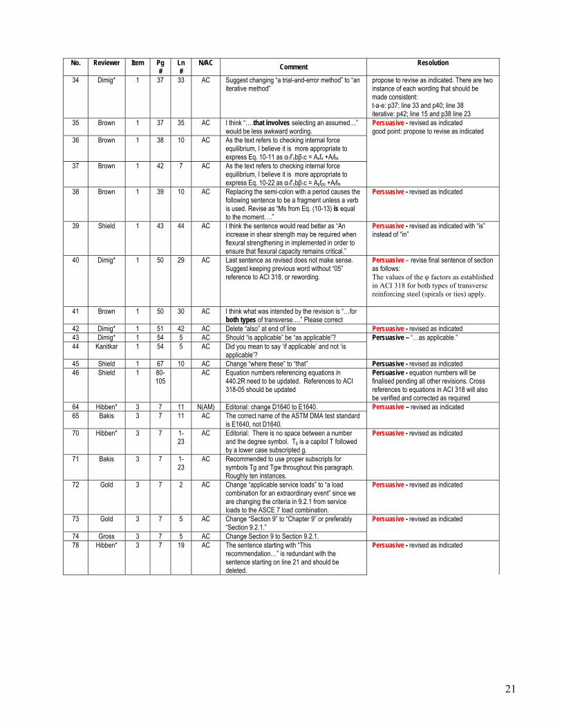
34 Dimig* 1 37 33 AC Suggest changing “a trial-and-error method” to “an iterative method”
propose to revise as indicated. There are two instance of each wording that should be made consistent: t-a-e: p37; line 33 and p40; line 38 iterative: p42; line 15 and p38 line 23
35 Brown 1 37 35 AC I think “….that involves selecting an assumed…” would be less awkward wording.
Persuasive - revised as indicated good point: propose to revise as indicated
36 Brown 1 38 10 AC As the text refers to checking internal force equilibrium, I believe it is more appropriate to express Eq. 10-11 as α1f’cbβ1c = Asfs +Afffe
37 Brown 1 42 7 AC As the text refers to checking internal force equilibrium, I believe it is more appropriate to express Eq. 10-22 as α1f’cbβ1c = Apfps +Afffe
38 Brown 1 39 10 AC Replacing the semi-colon with a period causes the following sentence to be a fragment unless a verb is used. Revise as “Ms from Eq. (10-13) is equal to the moment….”
Persuasive - revised as indicated
39 Shield 1 43 44 AC I think the sentence would read better as “An increase in shear strength may be required when flexural strengthening in implemented in order to ensure that flexural capacity remains critical.”
Persuasive - revised as indicated with “is” instead of “in”
40 Dimig* 1 50 29 AC Last sentence as revised does not make sense. Suggest keeping previous word without “05” reference to ACI 318, or rewording.
Persuasive – revise final sentence of section as follows: The values of the φ factors as established in ACI 318 for both types of transverse reinforcing steel (spirals or ties) apply.
41 Brown 1 50 30 AC I think what was intended by the revision is “…for both types of transverse….” Please correct
42 Dimig* 1 51 42 AC Delete “also” at end of line Persuasive - revised as indicated 43 Dimig* 1 54 5 AC Should “is applicable” be “as applicable”? Persuasive – “…as applicable.” 44 Kanitkar 1 54 5 AC Did you mean to say ‘if applicable’ and not ‘is
applicable’? 45 Shield 1 67 10 AC Change “where these” to “that” Persuasive - revised as indicated 46 Shield 1 80-
105 AC Equation numbers referencing equations in
440.2R need to be updated. References to ACI 318-05 should be updated
Persuasive - equation numbers will be finalised pending all other revisions. Cross references to equations in ACI 318 will also be verified and corrected as required
64 Hibben* 3 7 11 N(AM) Editorial: change D1640 to E1640. Persuasive – revised as indicated 65 Bakis 3 7 11 AC The correct name of the ASTM DMA test standard
is E1640, not D1640. 70 Hibben* 3 7 1-
23 AC Editorial: There is no space between a number
and the degree symbol. Tg is a capitol T followed by a lower case subscripted g.
Persuasive - revised as indicated
71 Bakis 3 7 1-23
AC Recommended to use proper subscripts for symbols Tg and Tgw throughout this paragraph. Roughly ten instances.
72 Gold 3 7 2 AC Change “applicable service loads” to “a load combination for an extraordinary event” since we are changing the criteria in 9.2.1 from service loads to the ASCE 7 load combination.
Persuasive - revised as indicated
73 Gold 3 7 5 AC Change “Section 9” to “Chapter 9” or preferably “Section 9.2.1.”
Persuasive - revised as indicated
74 Gross 3 7 5 AC Change Section 9 to Section 9.2.1. 78 Hibben* 3 7 19 AC The sentence starting with “This
recommendation…” is redundant with the sentence starting on line 21 and should be deleted.
Persuasive - revised as indicated

22
No. Reviewer Item Pg #
Ln #
N/AC Comment
Resolution
79 Dimig* 3 7 19-23
AC In Line 19, it states “This recommendation is for elevated service temperatures such as those found in hot regions or certain industrial environments.” Then in Line 21 it states “Testing may be required to determine the critical service temperature for FRP in other environments such as those found in hot regions or certain industrial environments.” These two statements seem contradictory and should be clarified. Should “such as those found in hot regions or certain industrial environments” be deleted from the second statement?
84 Gold 4 46 27 N We should also clarify here that the ψf factor for anchored U-wraps should be 0.85 (not 0.95 used for fully wrapped sections). Or mention this in the paragraph starting on Pg 44, Ln 42 where we talk about ψf factors.
Persuasive – revise as follows: “…Properly anchored U-wraps can be designed to fail by FRP rupture (NCHRP-678 2011). In no case, however, should the effective strain in the anchored FRP U-wrap exceed the lesser of 0.004 or 0.75εfu, whichever is smaller, and Ψf = 0.85 remains appropriate for anchored U-wraps. Revision addresses negative per email 3.30.15
85 Lopez 4 34 39 AC Figure X doesn’t appear in the final pdf version of the 440.2R document. Also, “X” should be changed to the appropriate number (New Figure 10.3 perhaps?)
Persuasive - revised as indicated (did not reorder Figures for ballot)
86 Lopez 4 46 29 AC Figure X doesn’t appear in the final pdf version of the 440.2R document. Also, “X” should be changed to the appropriate number (New Figure 10.3 perhaps?)
87 Brown 4 46 29 AC Please provide correct figure number 89 Alkhrdaji 4 34 40 AC Delete “Numerical and”. Persuasive - revised as indicated 90 Shield 4 34 41-
42 AC Consider deleting “the level of” Persuasive - revised as indicated
91 Shield 4 51 37 AC Consider deleting “the level of” 92 Dimig* 4 46 30 AC Suggest changing “Properly anchored U-wraps
can be designed to fail by FRP rupture.” to “Anchoring systems for U-wraps can be designed to prevent debonding of the FRP prior to rupture of the FRP.”
Persuasive - revised as indicated
93 Bakis 4 51 52,53
AC Use italics for letters used as math symbols and use proper subscripts as needed.
Persuasive - revised as indicated
94 Parretti 4 51 52 AC Add “of” between “2/3” and “the” Persuasive - revised as indicated 95 Myers 4 61 42 AC remove brackets around 2003 add comma after
year. Review all added references to be consistent with ACI requirements.
Persuasive - revised as indicated
96 Myers 4 61 50 AC should read "...Ibell T.J. 2005 ...." Persuasive - revised as indicated 97 Myers 4 62 14 AC remove bracket after 2013 Persuasive - revised as indicated 98 Seracino 4 AC Text (NSM U-anchor), and heading of Figure X(c)
(NSM anchor) should be made consistent. My recommendation is ‘NSM anchor’ makes more sense. The former implies to me that the NSM system is a U-anchor, which is of course not possible.
Persuasive - revised as indicated
116 Bakis 6 43 27 AC Use proper subscript for epsilon sub t. Persuasive - revised as indicated 117 Seracino 6 43 27 AC Make ‘t’ a subscript to strain.
124 Gold 7 44 20 AC The degree symbol after 90 needs to be fixed. Persuasive - revised as indicated 126 Seracino 7 44 20 AC Degrees symbol for angle should be a superscript. 131 Alkhrdaji 8 30 39 AC Insert the following after “thermal protection”:
“to existing concrete and internal steel.” To clarify the intend of the external fire protection for this condition.
Persuasive - revised as follows: …to existing concrete and internal reinforcing steel.
132 Thomas 8 30 39 AC Add to Line 39 after the word protection “to the reinforcing steel and concrete”
135 Alkhrdaji 8 30 45 AC Replace” This concept is used in ACI 216R to provide” with “ACI 216R provides”
Persuasive - revised as indicated

23
No. Reviewer Item Pg #
Ln #
N/AC Comment
Resolution
136 Alkhrdaji 8 30 47 AC Replace “concept established” with “method” Persuasive - revised as indicated *Non-voting reviewer Motion #5 was seconded by Witt. Shield opened the floor for discussion on the motion. There was no discussion. Upon hearing the motion, the motion was put to a vote. 28 members voted “affirmative”, 0 members voted “no”, and 0 members abstained. The motion carries. --------- Harries noted that Ballot Item #10 had no comments. He then presented comments and proposed resolution to Ballot Item #1.
Motion #6: Harries moved to find following comments persuasive and resolve these comments as indicated in the following table:
No. Reviewer Item Pg #
Ln #
N/AC Comment
Resolution
1 Blaszak 1 5 45 N Should not be used. Discouraged is not strong enough.
Persuasive - Revise as follows: These systems should not be used as compressive reinforcement.
29 Kanitkar 1 19 12 AC Why not leave the strain limits out and say ‘Young’s modulus should be calculated in accordance with ASTM D7565.’ That would make our document independent of changes in the ASTM document.
Persuasive - suggest: Young’s modulus should be calculated in accordance with the appropriate ASTM Standard, D3039, D7502 or D7565.
30 Lee 1 27 6 AC Since P22/L43 inserted a comment about moisture condition, I suggest that the following be added to end of Line 6: “, or as recommended by FRP system manufacturer.” This is to allow manufacture to specify test method other than using plastic mat, which is only one listed in ACI 503.4R. (Also suggest that “surface dryness” be changed to “surface moisture”.)
Persuasive revise “surface dryness” to “surface moisture” do not add manufacturer reference; it could be added to most all bullets in this list.
Motion #6 was seconded by Witt. Shield opened the floor for discussion on the motion. There was no discussion. Upon hearing the motion, the motion was put to a vote. 29 members voted “affirmative”, 0 members voted “no”, and 0 members abstained. The motion carries. --------- Shield indicated that the subcommittee did a good job of reviewing the document holistically. She indicated that this is good practice before sending these documents to TAC and should be continued. Harries then presented the comments from the sustainability section. This was sent out to the committee members just prior to this meeting for review. Harries indicated that Prota had an additional comment that he failed to include in his ballot that was received at the last minute. Harries indicated that this would be a nice addition with good references. Busel indicated that the references are very good upon cursory review.

24
Motion #7: Harries moved to find following comments persuasive and resolve these comments as indicated in the following table and to also find Prota’s comment persuasive and resolve as shown in the revised paragraph and additional references shown:
No. Reviewer Item Pg #
Ln #
N/AC Comment
Resolution
48 Blaszak 2 4 28-53
N I think this is way too much detail for the sustainability section. Propose keeping this section as general with the main message that even though the materials themselves are not sustainable (not able to recycle, large embedded energy, etc.), they contribute to the overall sustainability of a structure by providing a sustainable alternate to traditional retrofit methods. The way it reads know, I may start specifying glass for all repairs since it appears to be more sustainable than carbon
Revisions of the entire paragraph based on the apparent intent of all comments are provided below this table proposed revisions satisfy voter comments per email 3.30.15
49 Vokshi* 2 4 28 AC Sustainability section does not discuss manufacturing of the resin which may have the most environmental impact with respect to the LCA discussion.
Persuasive - Added the following sentence: The embodied energy and potential environmental impact of resin and adhesive systems are less studied although the volume used is also small in comparison to conventional methods of construction.
50 Alkhrdaji 2 4 33 AC The statement does not make it glass has lower or greeted energy consumption than steel.
Persuasive - Sentence revised for more specificity: Although carbon and glass fibers have high embodied energies associated with production – on the order of 200 and 20 mJ/kg, respectively (Howarth et al. 2014), the overall weight produced and used is orders of magnitude lower than steel (13 mJ/kg), concrete (1 mJ/kg) and reinforcing steel (9 mJ/kg) (Griffin and Hsu 2010).
51 Koch* 2 AC 4th sentence is hard to read. “During production glass fiber has a lower.....greater than steel”; Consider revising to “During production glass fiber has a lower relative energy consumption than carbon fiber but both are greater than steel”
52 Lee 2 3 AC 1.1.1; 4th sentence. It is stated that glass has lower energy consumption than carbon, while consumption for carbon is greater than steel. Where does glass fall relative to steel? If both glass and carbon are greater than steel, please clarify text.
53 Bradberry 2 4 36-38
AC Revise the sentence that starts on line 36 to read as follows: “For installation and use, FRP composites are characterized as having a longer service life as they are more durable—require less maintenance—than conventional materialsrequiring less maintenance.” Rationale: Placing the phrase “requiring less maintenance” at the end of the sentence confuses the read as to which material, conventional or FRP composites, requires less maintenance even though in it is clear from the first half of the sentence that FRP composites gets the kudos.
Persuasive - revised as indicated
54 Hibben* 2 4 40 AC Delete from “It is difficult” to the end of the paragraph. The discussion of the Dreamliner and advantages that technology will bring to this field are speculative.
Persuasive - Aircraft example removed; Comment #xx implemented as follows: Today, the market for recycled composite materials is small although aircraft manufacturers, in particular, are considering methods and programs to recycle and repurpose composite materials at the end of an aircraft’s life cycle.
55 Alkhrdaji 2 4 42-47
AC Too much details on aircraft market. Not related to externally bonded FRP or 440.2R. It should be included in 440R instead.
56 Gold 2 4 42 -
47
AC The statements beginning “One example…” to the end of the paragraph seem a bit detailed and anecdotal. Consider changing to “However, aircraft manufacturers, in particular, are considering methods and programs to recycle and repurpose composite materials at the end of an aircraft’s life cycle.”
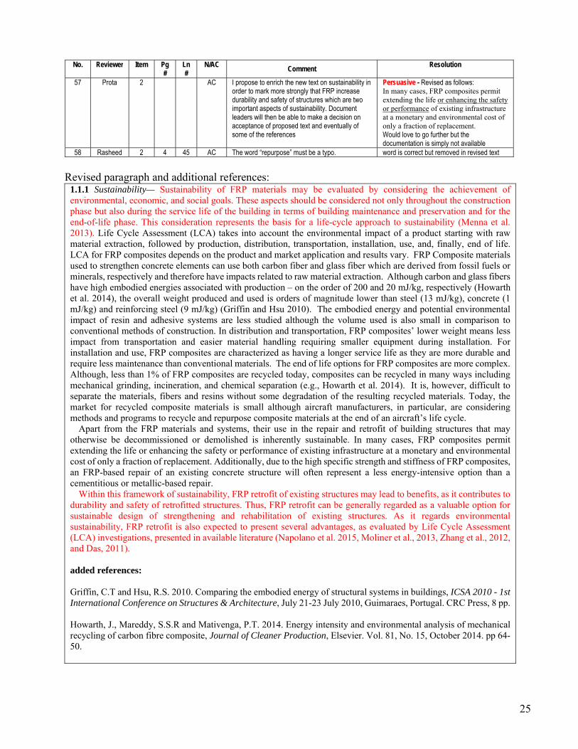
25
No. Reviewer Item Pg #
Ln #
N/AC Comment
Resolution
57 Prota 2 AC I propose to enrich the new text on sustainability in order to mark more strongly that FRP increase durability and safety of structures which are two important aspects of sustainability. Document leaders will then be able to make a decision on acceptance of proposed text and eventually of some of the references
Persuasive - Revised as follows: In many cases, FRP composites permit extending the life or enhancing the safety or performance of existing infrastructure at a monetary and environmental cost of only a fraction of replacement. Would love to go further but the documentation is simply not available
58 Rasheed 2 4 45 AC The word “repurpose” must be a typo. word is correct but removed in revised text
Revised paragraph and additional references:
1.1.1 Sustainability— Sustainability of FRP materials may be evaluated by considering the achievement of environmental, economic, and social goals. These aspects should be considered not only throughout the construction phase but also during the service life of the building in terms of building maintenance and preservation and for the end-of-life phase. This consideration represents the basis for a life-cycle approach to sustainability (Menna et al. 2013). Life Cycle Assessment (LCA) takes into account the environmental impact of a product starting with raw material extraction, followed by production, distribution, transportation, installation, use, and, finally, end of life. LCA for FRP composites depends on the product and market application and results vary. FRP Composite materials used to strengthen concrete elements can use both carbon fiber and glass fiber which are derived from fossil fuels or minerals, respectively and therefore have impacts related to raw material extraction. Although carbon and glass fibers have high embodied energies associated with production – on the order of 200 and 20 mJ/kg, respectively (Howarth et al. 2014), the overall weight produced and used is orders of magnitude lower than steel (13 mJ/kg), concrete (1 mJ/kg) and reinforcing steel (9 mJ/kg) (Griffin and Hsu 2010). The embodied energy and potential environmental impact of resin and adhesive systems are less studied although the volume used is also small in comparison to conventional methods of construction. In distribution and transportation, FRP composites’ lower weight means less impact from transportation and easier material handling requiring smaller equipment during installation. For installation and use, FRP composites are characterized as having a longer service life as they are more durable and require less maintenance than conventional materials. The end of life options for FRP composites are more complex. Although, less than 1% of FRP composites are recycled today, composites can be recycled in many ways including mechanical grinding, incineration, and chemical separation (e.g., Howarth et al. 2014). It is, however, difficult to separate the materials, fibers and resins without some degradation of the resulting recycled materials. Today, the market for recycled composite materials is small although aircraft manufacturers, in particular, are considering methods and programs to recycle and repurpose composite materials at the end of an aircraft’s life cycle.
Apart from the FRP materials and systems, their use in the repair and retrofit of building structures that may otherwise be decommissioned or demolished is inherently sustainable. In many cases, FRP composites permit extending the life or enhancing the safety or performance of existing infrastructure at a monetary and environmental cost of only a fraction of replacement. Additionally, due to the high specific strength and stiffness of FRP composites, an FRP-based repair of an existing concrete structure will often represent a less energy-intensive option than a cementitious or metallic-based repair.
Within this framework of sustainability, FRP retrofit of existing structures may lead to benefits, as it contributes to durability and safety of retrofitted structures. Thus, FRP retrofit can be generally regarded as a valuable option for sustainable design of strengthening and rehabilitation of existing structures. As it regards environmental sustainability, FRP retrofit is also expected to present several advantages, as evaluated by Life Cycle Assessment (LCA) investigations, presented in available literature (Napolano et al. 2015, Moliner et al., 2013, Zhang et al., 2012, and Das, 2011).
added references: Griffin, C.T and Hsu, R.S. 2010. Comparing the embodied energy of structural systems in buildings, ICSA 2010 - 1st International Conference on Structures & Architecture, July 21-23 July 2010, Guimaraes, Portugal. CRC Press, 8 pp. Howarth, J., Mareddy, S.S.R and Mativenga, P.T. 2014. Energy intensity and environmental analysis of mechanical recycling of carbon fibre composite, Journal of Cleaner Production, Elsevier. Vol. 81, No. 15, October 2014. pp 64-50.

26
Menna, C., Asprone, D., Jalayer, F., Prota, A., & Manfredi, G. (2013). Assessment of ecological sustainability of a building subjected to potential seismic events during its lifetime. The International Journal of Life Cycle Assessment, 18(2), 504-515. Napolano, L., Menna, C., Asprone, D., Prota, A., & Manfredi, G. (2015). LCA-based study on structural retrofit options for masonry buildings. The International Journal of Life Cycle Assessment, 20(1), 23-35.
Motion #7 was seconded by Witt. Shield opened the floor for discussion on the motion. Bank indicated that we are presenting this for the first time and the committee has not had time to review. Shield indicated that we are presenting it here as a matter of resolving negatives. Bank questioned whether the last statements are “green-washing”. Harries indicated that the references provide some basis without “green-washing”. Bank offered additional editing to the final statement. Nanni indicated that Prota was trying to provide context and that we should allow the specific wording to be edited accordingly. Shield asked for those interested in the specific wording to revise. Shield amended the motion to keep the concepts unchanged and a small task group to modify the wording (Shield, Harries, Bank, Gold, Prota). Upon hearing the motion, the motion was put to a vote. 29 members voted “affirmative”, 0 members voted “no”, and 0 members abstained. The motion carries. --------- Harries then presented a series of comments on the discussion of the glass transition temperature. Motion #8: Harries moved to find following comments persuasive and resolve these comments as indicated in the following table:
No. Reviewer Item Pg #
Ln #
N/AC Comment
Resolution
60 Bouadi 3 N Change “for example, FRP with a fire-protection system” to “for example FRP system with a fire protection system that is demonstrated to keep the FRP and the FRP-to-substrate interface below Tg”
Persuasive - delete parenthetical entirely in this introductory section Because of the degradation of most FRP materials at high temperature, the strength of externally bonded FRP systems is assumed to be lost completely in a fire, unless it can be demonstrated that the FRP will remain effective for the required duration of the fire (for example, FRP with a fire-protection system).
62 Gold 3 6 54 N Delete “(for example, FRP with a fire-protection system)” This implies that a fire protection system is all that is needed to make the FRP effective in a fire. Fire protection systems generally provide additional insulation for the underlying concrete as we state later in 9.2.1 (Pg 30, Ln 38)
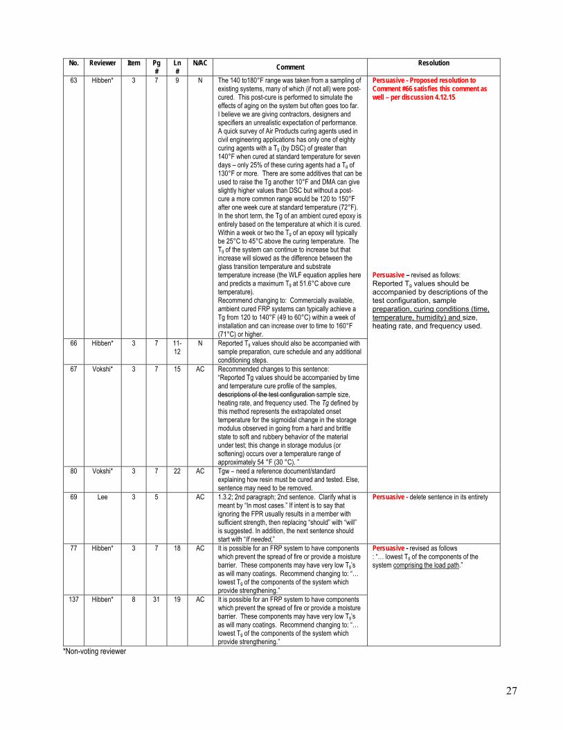
27
No. Reviewer Item Pg #
Ln #
N/AC Comment
Resolution
63 Hibben* 3 7 9 N The 140 to180°F range was taken from a sampling of existing systems, many of which (if not all) were post-cured. This post-cure is performed to simulate the effects of aging on the system but often goes too far. I believe we are giving contractors, designers and specifiers an unrealistic expectation of performance. A quick survey of Air Products curing agents used in civil engineering applications has only one of eighty curing agents with a Tg (by DSC) of greater than 140°F when cured at standard temperature for seven days – only 25% of these curing agents had a Tg of 130°F or more. There are some additives that can be used to raise the Tg another 10°F and DMA can give slightly higher values than DSC but without a post-cure a more common range would be 120 to 150°F after one week cure at standard temperature (72°F). In the short term, the Tg of an ambient cured epoxy is entirely based on the temperature at which it is cured. Within a week or two the Tg of an epoxy will typically be 25°C to 45°C above the curing temperature. The Tg of the system can continue to increase but that increase will slowed as the difference between the glass transition temperature and substrate temperature increase (the WLF equation applies here and predicts a maximum Tg at 51.6°C above cure temperature). Recommend changing to: Commercially available, ambient cured FRP systems can typically achieve a Tg from 120 to 140°F (49 to 60°C) within a week of installation and can increase over to time to 160°F (71°C) or higher.
Persuasive - Proposed resolution to Comment #66 satisfies this comment as well – per discussion 4.12.15 Persuasive – revised as follows: Reported Tg values should be accompanied by descriptions of the test configuration, sample preparation, curing conditions (time, temperature, humidity) and size, heating rate, and frequency used.
66 Hibben* 3 7 11-12
N Reported Tg values should also be accompanied with sample preparation, cure schedule and any additional conditioning steps.
67 Vokshi* 3 7 15 AC Recommended changes to this sentence: “Reported Tg values should be accompanied by time and temperature cure profile of the samples, descriptions of the test configuration sample size, heating rate, and frequency used. The Tg defined by this method represents the extrapolated onset temperature for the sigmoidal change in the storage modulus observed in going from a hard and brittle state to soft and rubbery behavior of the material under test; this change in storage modulus (or softening) occurs over a temperature range of approximately 54 °F (30 °C). ”
80 Vokshi* 3 7 22 AC Tgw – need a reference document/standard explaining how resin must be cured and tested. Else, sentence may need to be removed.
69 Lee 3 5 AC 1.3.2; 2nd paragraph; 2nd sentence. Clarify what is meant by “In most cases.” If intent is to say that ignoring the FPR usually results in a member with sufficient strength, then replacing “should” with “will” is suggested. In addition, the next sentence should start with “If needed,”
Persuasive - delete sentence in its entirety
77 Hibben* 3 7 18 AC It is possible for an FRP system to have components which prevent the spread of fire or provide a moisture barrier. These components may have very low Tg’s as will many coatings. Recommend changing to: “… lowest Tg of the components of the system which provide strengthening.”
Persuasive - revised as follows : “… lowest Tg of the components of the system comprising the load path.”
137 Hibben* 8 31 19 AC It is possible for an FRP system to have components which prevent the spread of fire or provide a moisture barrier. These components may have very low Tg’s as will many coatings. Recommend changing to: “… lowest Tg of the components of the system which provide strengthening.”
*Non-voting reviewer

28
Motion #8 was seconded by Witt. Shield opened the floor for discussion on the motion. There was no discussion. Upon hearing the motion, the motion was put to a vote. 26 members voted “affirmative”, 0 members voted “no”, and 0 members abstained. The motion carries. --------- Harries then presented a series of comments on Ballot Items #7 and #9. Motion #9: Harries moved to find following comments persuasive and resolve these comments as indicated in the following table:
No. Reviewer Item Pg #
Ln #
N/AC Comment Resolution
121 Gold 7 44 24 N There are details (weep channels and weep holes) that can be employed to allow moisture migration through continuous reinforcement (as well as resin systems that are vapor permeable). This statement is also relatively vague about what “complete encasement” is. Suggest rewording last sentence to be “As discussed in Section 9.3.3, the potential effects of entrapping moisture in the substrate when using continuous reinforcement should be carefully considered. Specific means of allowing moisture vapor transmission out of the substrate should be employed where appropriate.”
Persuasive – revised as indicated by Gold. Revision eliminates conflict in section 11.2 that was overlooked in editing
122 Dimig* 7 44 23 AC “As discussed in Section 9.3.3, the use of continuous FRP reinforcement that completely encases a member and potentially prevents migration of moisture should not be used.” The current version states “is discouraged” rather than “should not be used,” which is more in line with the discussion in Section 9.3.3 which suggests this may be done if adequate means is provided to allow moisture to escape. Suggestion: “The use of continuous FRP reinforcement that completely encases a member and potentially prevents migration of moisture requires special considerations as discussed in Section 9.3.3.”
123 Dimig* 7 45 12 AC To be consistent with ACI 318 11.2.3 and the illustration of dfv for rectangular sections in Figure 11.2, it seems dfv for a circular section should be equal to 0.8 times the diameter of the section. On a side note, the dimension dfv for a rectangular section is not clearly defined in 440. Figure 11.2 and example problem 15.6 are provided in which dfv extends from the top of the FRP wrap to the center of the bottom longitudinal reinforcing steel. Is this definition applicable to continuous beams where the section requiring shear reinforcement is in negative bending? Consideration should be given to providing clarification on how dfv is to be defined for rectangular sections.
Persuasive - Revise as follows: “For circular sections, dfv is taken as 0.8 times the diameter of the section and…”

29
No. Reviewer Item Pg #
Ln #
N/AC Comment
Resolution
140 Alkhrdaji 9 48 36 N The original intent of this section is to use eccu equation to calculate the stiffness E2 in equation 12-2b and the strength fc in 12-2a. The limit of 0.01 is applied to fc only to excessive cracking and loss of section integrity. The new combined equation does not make it clear that the eccu limit of 0.01 applies ONLY to fc but not E2. Combining eccu and 0.01 in one equation may imply that the limit of 0.01 can also be used to calculate E2 which is not correct and will lead to artificially high E2 value.
Proposed changes: a) Move new statement on lines 33-34 to
immediately after equation 12-4. Modify as follows: “ If the ultimate strain of confined concrete eccu is greater than 0.01 then the confined concrete strength should be calculated using Eq. (12-2).”
Remove <= 0.01 from equation 12-6.
Persuasive – Propose: Eq. 12-2a limit: εt’ ≤ εc ≤ εc,max add Eq 12-2b: εc,max = εccu ≤ 0.01 The maximum compressive strain in the FRP-confined concrete εccu can be found using Eq. (12-6) (Concrete Society 2004). This strain should be limited to 0.01 to prevent excessive cracking and the resulting loss of concrete integrity. When this limit is applicable, the corresponding maximum value of fcc’ should be recalculated from the stress-strain curve given by Eq. (12-2) (Concrete Society 2004). revision acceptable to voter per email 4.13.15
*Non-voting reviewer
Motion #9 was seconded by Witt. Shield opened the floor for discussion on the motion. There was no discussion. Upon hearing the motion, the motion was put to a vote. 28 members voted “affirmative”, 0 members voted “no”, and 0 members abstained. The motion carries. --------- Harries then presented a series of comments on the structural fire endurance rating recommendations. Shield indicated that in speaking with the Chair of ACI Committee 562, there is still not consensus in ACI Committee 562 on the equation using Ak. We should not change our document to try to anticipate what the equation in ACI 562 will be. Harries indicated that we are presenting both the existing ACI 562 equation and the ACI 216R equation with the recommended approach being the ACI 216R equation. Motion #10: Harries moved to find following comments persuasive and resolve these comments as indicated in the following table:
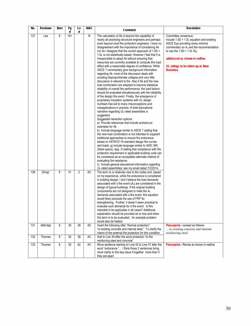
30
No. Reviewer Item Pg #
Ln #
N/AC Comment
Resolution
127 Lee 8 16+ N The calculation of Ak is beyond the capability of nearly all practicing structural engineers and perhaps even beyond most fire protection engineers. I have no disagreement with the importance of considering Ak nor do I disagree that the current approach of 1.0D + 1.0L is not statistically based. However I feel that it is irresponsible to adopt Ak without ensuring that resources are currently available to compute this load effect with a reasonable degree of confidence. While ASCE 7 commentary give background information regarding Ak, most of the discussion deals with avoiding disproportionate collapse and very little discussion is relevant to fire. Also if Ak and the new load combination are adopted to improve statistical reliability of overall fire performance, the load factors should be evaluated simultaneously with the reliability of the design fire event. Finally, the emergence of proprietary insulation systems with UL design numbers has led to many misconceptions and misapplications in practice. A brief educational narrative regarding UL-rated assemblies is suggested. Suggested resolution options: a) Provide references that include worked-out examples for Ak b) Include language similar to ASCE 7 stating that the new load combination is not intended to supplant traditional approaches to ensure fire endurance based on ASTM E119 standard design fire curves and loads, or include language similar to AISC 360 (Steel specs), App. D stating that compliance with fire protection requirement in applicable building code can be considered as an acceptable alternate method of evaluating fire resistance. c) Include general educational information regarding UL-rated assemblies; see my email dated 7/2/2014.
Committee consensus: include 1.0D + 1.0L equation and existing ASCE Eqs providing some minimal commentary on Ak and the recommendation to use the 1.0D + 1.0L Eq. addressed as shown in redline UL ratings to be taken up as New Business.
128 Dimig* 8 31 2 AC The term Ak is relatively new to the codes and, based on my experience, while fire endurance is considered in building design, I don’t believe the load demands associated with a fire event (Ak) are considered in the design of typical buildings. If the original building components are not designed to meet the Ak
demands associated with a fire event, this equation would likely preclude the use of FRP for strengthening. Further, it doesn’t seem practical to evaluate such demands for a fire event. Is this intended to be applicable in all cases? Additional explanation should be provided as to how and when this term is to be evaluated. An example problem would also be helpful.
131 Alkhrdaji 8 30 39 AC Insert the following after “thermal protection”: “to existing concrete and internal steel.” To clarify the intend of the external fire protection for this condition.
Persuasive - revised as follows: …to existing concrete and internal reinforcing steel.
132 Thomas 8 30 39 AC Add to Line 39 after the word protection “to the reinforcing steel and concrete”
133 Thomas 8 30 42 AC Move sentence starting on Line 42 to Line 37 after the word “endurance.”… I think those 2 sentences bring more clarity to this key issue if together more than if they are apart
Persuasive - Revise as shown in redline

31
No. Reviewer Item Pg #
Ln #
N/AC Comment
Resolution
134 Vokshi* 8 The next two paragraphs seem very wordy. I believe it can be consolidated as follows: “When considering the fire endurance of an FRP-strengthened concrete element, it is important to recognize that the strength of a reinforced concrete element is reduced during fire exposure due to heating of both the reinforcing steel and the concrete. This concept is used in ACI 216R to provide methods for determining the reduced strength of a reinforced concrete member due to fire exposure and for computing the fire rating of the member. By extending the concepts established in ACI 216R “Fire Resistance and Fire Protection of Structures” to FRP strengthened reinforced concrete, limits on strengthening can be used to ensure a strengthened structure will not collapse in a fire event. A member’s resistance to load effects, with reduced steel and concrete strengths and without the contribution of the FRP reinforcement, can be computed. This resistance can then be compared with the load demand on the member during the fire event. to ensure the strengthened member can support these loads for the required fire duration (or fire rating time) without failure."
135 Alkhrdaji 8 30 45 AC Replace” This concept is used in ACI 216R to provide” with “ACI 216R provides”
Persuasive – revision not required, sentence removed (see comments #133-134)
136 Alkhrdaji 8 30 47 AC Replace “concept established” with “method” Persuasive - revised as indicated 137 Hibben* 8 31 19 AC It is possible for an FRP system to have components
which prevent the spread of fire or provide a moisture barrier. These components may have very low Tg’s as will many coatings. Recommend changing to: “… lowest Tg of the components of the system which provide strengthening.”
Persuasive - revised as indicated; see comment #77
*Non-voting reviewer
Motion #10 was seconded by Witt. Shield opened the floor for discussion on the motion. Lee offered a friendly amendment to change reference to ACI 562 to ACI 562-13 and to change “fire endurance” to “fire resistance” throughout the document. Lee also indicated that he would like to add a sentence at the end of paragraph 2 in Section 9.2.1: “However to attain desired fire rating, the specifier should properly evaluate the ability of the existing structure and proposed insulating system to provide the enhanced performance.” Lee indicated that this sentence does not specifically address the UL ratings that are being used in the industry, but that should be taken as new business and perhaps generate a TechNote addressing how UL ratings are obtained and used. Bouadi indicated that he would like to include statements on the proper use of UL ratings directly in the ACI 440.2R document. Bouadi also asked for additional modifications to more strongly state that the FRP will be lost in a fire. Blaszak indicated that this may be too strong for some systems that have a higher glass transition temperature. Harries indicated that he is not comfortable with these resolutions. The changes proposed are going beyond just resolving the negatives. Green, Bisby, and Alkhrdaji are not present to defend their arguments, but they have indicated by e-mail that they disagree with some of the proposed changes offered. Shield indicated that there are three options: 1) we can pull this ballot item completely and not modify this section of the document, 2) we can make some minor changes that will resolve Lee’s concerns, or 3) we can vote to find Lee non-persuasive. Bank indicated that the paragraph also implies that this is just a glass transition temperature issue, whereas the polymer is completely lost at high temperatures that would be experienced in a fire. Shield indicates that we will take this as new business. Lee indicated that he would like to make the industry aware of the limitations of fire protection systems and of the UL ratings associated with these systems, because otherwise fire protection systems will continue to be promoted. He suggested that this could be a disadvantage for the industry due to the cost and difficulty in installation of these systems.

32
Reyes expressed his opinion that offering UL rated systems benefits the industry because it allows building officials to approve FRP strengthening systems in fire rated structures. Ekenel indicated that the building official can only rely on testing from ASTM E119 or by calculation, since there is no calculation method it does not help the code official. Lee indicated that it is common in Texas for code officials to divert to the engineer of record. Bouadi also indicated that he calculates this fire resistance based on the methods and equations in ACI 440.2R. He expressed that he feels it is misleading to submit a UL rating based on a tested system that is not representative of the actual strengthened element. Shield asked to get a straw poll to see where the committee stands. The poll indicated that five members were strongly in favor of adding the language that Lee suggested and five members were opposed to this language. Shield reiterated that we can either have Lee withdraw the negative, find him non-persuasive, or pull the entire ballot item. Shield indicated that those opposed to adding this language are not comfortable with making this change without more discussion and consideration by experts not represented today. Lee indicated that he feels this needs to be dealt with now given how fire protection systems are currently being used in the industry. Harries moved to find the part of Lee’s negative #127 associated with UL ratings as non-persuasive. This motion was seconded by Bradberry. Shield opened the floor for discussion on the motion. There was no discussion. Upon hearing the motion, the motion was put to a vote. 22 members voted “affirmative”, 3 members voted “no” (Lee, Blaszak, Bouadi), and 3 members abstained (Kim, Tumialan, Shessepa). The motion carries. Shield indicated that we will not add the sentence that Lee proposed to the end of the second paragraph in this section. She indicated that we will, however, take as new business both continued work on the Task Group and the drafting of a TechNote related to UL ratings and fire protection systems. Both Lee and Ekenel volunteer to work on this. The amended section 9.2.1 was presented as follows:
9.2.1 Structural fire resistance — The level of strengthening that can be achieved through the use of externally bonded FRP reinforcement can be limited by the code-required fire-resistance rating of a structure. The polymer resins typically used in wet layup and prepreg FRP systems and the polymer adhesives used in precured FRP systems suffer deterioration of mechanical and bond properties at temperatures close to or exceeding the Tg of the polymer, as described in Section 1.3.3.
Although the FRP system itself is significantly affected by exposure to elevated temperature, a combination of the FRP system with an existing concrete structure may still have an adequate fire resistance. In cases in which the concrete member without the FRP system may possess sufficient fire resistance to resist loads during a fire. When considering the fire endurance of an FRP-strengthened concrete element, it is important to recognize that the strength of a reinforced concrete element is reduced during fire exposure due to heating of both the reinforcing steel and the concrete. Performance in fire of the existing concrete member can be enhanced by installing an insulation system, which will provide thermal protection to existing concrete and internal reinforcing steel, thus improving the overall fire-rating, although the FRP system contribution may be reduced (Bisby et al. 2005a; Williams et al. 2006; Palmieri et al. 2011; Firmo et al. 2012).
By extending the methods in ACI 216R to FRP-strengthened reinforced concrete, limits on strengthening can be used to ensure a strengthened structure will not collapse in a fire event. A member’s resistance to load effects, with reduced steel and concrete strengths and without the contribution of the FRP reinforcement, can be compared with the load demand on the member during the fire event to ensure the strengthened member can support these loads for the required fire duration (or fire rating time) without failure:
Rn 1.0SDL + 1.0SLL (9-2)

33
Alternately, ACI 562-13 specifies the following: Rn 1.2SDL + 0.5SLL + 0.2SSL+ 1.0Ak (9-3) here Rn is the nominal resistance of the member at an elevated temperature, SDL, SLL, and SSL are the specified dead, live, and snow loads, respectively, calculated for the strengthened structure. For cases where the design live load has a high likelihood of being present for a sustained period of time, a live load factor of 1.0 should be used in place of 0.5 in Eq. (9-3). Due to the lack of guidance for the calculation of Ak, the load or load effect resulting from the fire event, use of Eq. 9-2 is recommended.
If the FRP system is meant to allow greater load-carrying capacity, such as an increase in live load, the load effects should be computed using these greater loads. If the FRP system is meant to address a loss in strength, such as deterioration, the resistance should reflect this loss.
The nominal resistance of the member at an elevated temperature Rn may be determined using the guidelines outlined in ACI 216R or through testing. The nominal resistance Rn should be calculated based on the reduced material properties of the existing member. The resistance should be computed for the time period required by the member’s fire-resistance rating—for example, a 2-hour fire rating—and should not account for the contribution of the FRP system unless the continued effectiveness of the FRP can be proven through testing. More research is needed to accurately identify temperatures at which effectiveness is lost for different types of FRP. Until better information on the properties of FRP at high temperature is available, the critical temperature can be taken as the lowest Tg of the components of the system comprising the load path.
Upon hearing the motion #10, the motion was put to a vote. 26 members voted “affirmative”, 1 member voted “no” (Lee), and 0 members abstained. Shield indicated that we now had to resolve Lee’s negative vote on the motion unless Lee agrees to withdraw his negative vote. Lee withdraws his negative vote and changes to abstention. The motion carries. --------- The committee thanked Harries, Witt, Lee, Silva, and Kanitkar for their efforts in updating this document to this point! Harries indicated that this was the work of many committee members; it was a true committee effort.
8. 440 Activities Overview 440-TG2 – Witt reported on the activities of the 440-TG2 task group on construction specifications for FRP strengthening systems. She indicated that the scope of the document was approved by TAC. The scope will be limited to concrete and masonry substrates and will only cover application of materials covered by the current material specification (ACI 440.8-13). Additionally, a working group met at this convention to further develop the initial draft started in Washington DC. This group started working on some of the more challenging portions of the document. An open meeting is planned at the Denver convention for additional input into the development of the document. Witt reported that she hopes that an initial ballot can be issued prior to the Milwaukee convention (Spring 2016).

34
440-H – Brown reported on the activities of the 440-H subcommittee. The 440.1R-15 document is now in publication. The subcommittee is now focusing its efforts on developing a design standard for FRP reinforced concrete. Brown presented the working outline for this document as follows:
Currently the development of this standard is on track. Phase 1 is to complete the so called “toolbox” chapters. A subcommittee ballot on these chapters is anticipated by this summer. Some of the larger outstanding issues with these chapters were discussed during the subcommittee meeting at this convention. Brown reported that one of those issues was whether we reference the ASTM D30.X bar specification (in development) or the ACI 440.6 bar specification for material characteristics. A small task group (Shield, Gentry, Benmokrane) has agreed to look at this issue and report back by June 30, 2015. Other issues that need to be resolved with these chapters are:
• Do we include columns/compression members? Do we have an equation for development lengths/splice lengths in compression?
• Do we include bundled bars? • Do we include torsion? • Deflection in two-way slabs? • Bar spacing for flexural crack control, what crack width limit should be used? • Temperature and shrinkage steel requirements? • Do we allow bond as a failure mode?
Brown indicated that the decision on whether to include columns in this document remains a significant question. There is a desire to include them, but it is not clear whether there is enough research and information on columns and related design issues to develop provisions for columns. Brown indicated that the subcommittee had been working under the assumption that this document would not include prestressed concrete. However, this has been a topic of debate. In order to clarify this issue, Brown made a motion to exclude prestressed concrete from the design standard for FRP
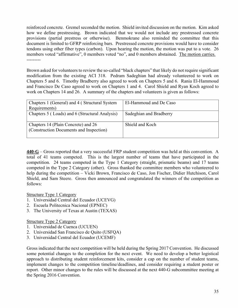
35
reinforced concrete. Gremel seconded the motion. Shield invited discussion on the motion. Kim asked how we define prestressing. Brown indicated that we would not include any prestressed concrete provisions (partial prestress or otherwise). Benmokrane also reminded the committee that this document is limited to GFRP reinforcing bars. Prestressed concrete provisions would have to consider tendons using other fiber types (carbon). Upon hearing the motion, the motion was put to a vote. 26 members voted “affirmative”, 0 members voted “no”, and 0 members abstained. The motion carries. --------- Brown asked for volunteers to review the so-called “black chapters” that likely do not require significant modification from the existing ACI 318. Pedram Sadeghian had already volunteered to work on Chapters 5 and 6. Timothy Bradberry also agreed to work on Chapters 5 and 6. Rania El-Hammoud and Francisco De Caso agreed to work on Chapters 1 and 4. Carol Shield and Ryan Koch agreed to work on Chapters 14 and 26. A summary of the chapters and volunteers is given as follows: Chapters 1 (General) and 4 ( Structural System Requirements)
El-Hammoud and De Caso
Chapters 5 ( Loads) and 6 (Structural Analysis)
Sadeghian and Bradberry
Chapters 14 (Plain Concrete) and 26 (Construction Documents and Inspection)
Shield and Koch
440-G – Gross reported that a very successful FRP student competition was held at this convention. A total of 41 teams competed. This is the largest number of teams that have participated in the competition. 24 teams competed in the Type 1 Category (straight, prismatic beams) and 17 teams competed in the Type 2 Category (other). Gross thanked the committee members who volunteered to help during the competition – Vicki Brown, Francisco de Caso, Jon Fischer, Didier Hutchison, Carol Shield, and Sam Steere. Gross then announced and congratulated the winners of the competition as follows: Structure Type 1 Category 1. Universidad Central del Ecuador (UCEVG) 2. Escuela Politecnica Nacional (EPNEC) 3. The University of Texas at Austin (TEXAS)
Structure Type 2 Category 1. Universidad de Cuenca (UCUEN) 2. Universidad San Francisco de Quito (USFQA) 3. Universidad Central del Ecuador (UCEMF) Gross indicated that the next competition will be held during the Spring 2017 Convention. He discussed some potential changes to the completion for the next event. We need to develop a better logistical approach to distributing student reinforcement kits, consider a cap on the number of student teams, implement changes to the competition timeline/deadlines, and consider requiring a student poster or report. Other minor changes to the rules will be discussed at the next 440-G subcommittee meeting at the Spring 2016 Convention.
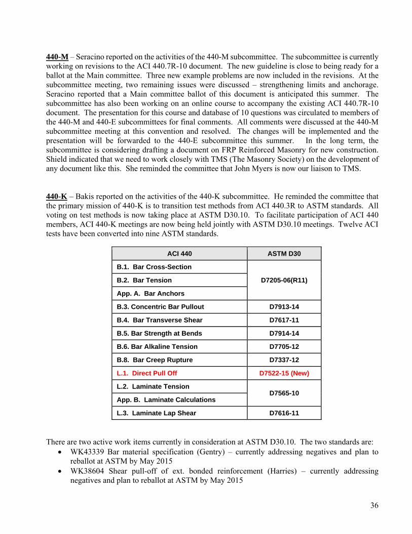
36
440-M – Seracino reported on the activities of the 440-M subcommittee. The subcommittee is currently working on revisions to the ACI 440.7R-10 document. The new guideline is close to being ready for a ballot at the Main committee. Three new example problems are now included in the revisions. At the subcommittee meeting, two remaining issues were discussed – strengthening limits and anchorage. Seracino reported that a Main committee ballot of this document is anticipated this summer. The subcommittee has also been working on an online course to accompany the existing ACI 440.7R-10 document. The presentation for this course and database of 10 questions was circulated to members of the 440-M and 440-E subcommittees for final comments. All comments were discussed at the 440-M subcommittee meeting at this convention and resolved. The changes will be implemented and the presentation will be forwarded to the 440-E subcommittee this summer. In the long term, the subcommittee is considering drafting a document on FRP Reinforced Masonry for new construction. Shield indicated that we need to work closely with TMS (The Masonry Society) on the development of any document like this. She reminded the committee that John Myers is now our liaison to TMS. 440-K – Bakis reported on the activities of the 440-K subcommittee. He reminded the committee that the primary mission of 440-K is to transition test methods from ACI 440.3R to ASTM standards. All voting on test methods is now taking place at ASTM D30.10. To facilitate participation of ACI 440 members, ACI 440-K meetings are now being held jointly with ASTM D30.10 meetings. Twelve ACI tests have been converted into nine ASTM standards.
ACI 440 ASTM D30
B.1. Bar Cross-Section
D7205-06(R11) B.2. Bar Tension
App. A. Bar Anchors
B.3. Concentric Bar Pullout D7913-14
B.4. Bar Transverse Shear D7617-11
B.5. Bar Strength at Bends D7914-14
B.6. Bar Alkaline Tension D7705-12
B.8. Bar Creep Rupture D7337-12
L.1. Direct Pull Off D7522-15 (New)
L.2. Laminate Tension D7565-10
App. B. Laminate Calculations
L.3. Laminate Lap Shear D7616-11
There are two active work items currently in consideration at ASTM D30.10. The two standards are:
WK43339 Bar material specification (Gentry) – currently addressing negatives and plan to reballot at ASTM by May 2015
WK38604 Shear pull-off of ext. bonded reinforcement (Harries) – currently addressing negatives and plan to reballot at ASTM by May 2015

37
There are now two ASTM standards that require review for reapproval. These are: • D7565/D7565M-2010 Test Method for Determining Tensile Properties of Fiber Reinforced
Polymer Matrix Composites Used for Strengthening of Civil Structures (Gentry) • D7205/D7205M-2011 Standard Test Method for Tensile Properties of Fiber Reinforced Polymer
Matrix Composite Bars (Bakis) The work on both of these documents involves mainly cleaning up terminology. There are also several new test methods being drafted and test methods from ACI 440.3R that are being transferred. These are: • ACI 440.3R B.9 Long-term relaxation of FRP bars (Jimmy Kim) • ACI 440.3R B.10 Bar anchorage (Jimmy Kim) • ACI 440.3R B.7 Bar Tensile Fatigue (DJ Belarbi) • ACI 440.3R B.11 Test methods for tensile properties of deflected FRP bars (DJ Belarbi) • Shear pull-off test for laminates (Maria Lopez) • Development Length (Max Porter) • A guide for preparation of wet layup specimens (Blaszak) • Guide for all D30.10 test methods If the four existing ACI 440.3R test methods above are successfully transferred to ASTM, we will have migrated all of the methods in ACI 440.3R to ASTM. Bakis announced the upcoming meetings for ASTM D30.10: • Fall 2015 meeting with Composite Materials Handbook Committee • Spring 2016 meeting with ACI 440K
– 17-21 April 2016, Milwaukee, WI • Fall 2016 with American Society of Composites Annual Conference
– 19-22 Sept. 2016, Williamsburg, VA Bakis encouraged committee members that wish to be involved in the development of these and all other test methods to join the ASTM D30 committee. 440-J – Busel reported on the activities of the 440-J subcommittee. The subcommittee is currently working on preparing a design guideline on concrete filled FRP tubes (CFFT). It will cover circular, prefabricated FRP tubes filled with concrete and their connections to other members. A first draft of the guide was sent to subcommittee members and also presented during the subcommittee’s last meeting in Washington DC. Based on feedback received, the following gaps in the document were identified: calibration of strength reduction factors, seismic design, and design of connections with starter bars. The calibration of strength reduction factors has since been started. Flexural capacity test data on CFFT’s were collected from the literature and a reliability analysis will be completed. Data and analysis for shear, axial load, and combined axial-bending will also need to be completed. Busel indicated that the subcommittee is currently lacking producer members and members who are end users. The subcommittee plans on establishing a review panel of end-users to help review the guide. The subcommittee hopes to revise the first draft, then issue the first subcommittee ballot.
38
440-I – Kim reported that the 440-I subcommittee is currently working on a revision to the 440.4R document. Draft revisions have been reviewed by the subcommittee and most technical and editorial comments from that review have been addressed. Technical items that still need to be addressed include: establishing effective moment of inertia equations, providing consistent minimum reinforcement ratios with ACI 440.1R and ACI 318, completing a reliability analysis of strength reduction factors, determining long term multipliers for deflection and camber, establishing the transition in strength reduction factors between tension-controlled and compression-controlled sections, and correcting errors in design examples. The subcommittee plans to issue a subcommittee ballot on the revisions by Fall 2015 and ballot the document at the Main committee level in 2016. ISO TC71-SC6 –Shield reported that Committee 440 is the official US representative to ISO TC71 Subcommittee 6 (Subcommittee 6 is on FRP Reinforcement). The TC71 chair is Dr. Uomoto (Japan). A recent document was successfully balloted: ISO 18319 Fibre-reinforced polymer (FRP) reinforcement for concrete structures – specification for FRP sheets. This document is similar to our repair material specification. The ISO document does not list minimum values for any properties, however. This document just lists properties that need to be considered. One item of note is that the ISO document does define a nominal thickness as the fiber mass per unit area of dry sheet divided by the density of the dry sheet. This may be something for us to consider in future revisions of our material specification. The next meeting of this subcommittee is in Korea in 2015. We will try to have someone from ACI Committee 440 attend.
9. New Business Shield invited any discussion of new business or reports from other ACI committees. Blaszak indicated that ICRI Committee 330 is nearing completion of a guide specification on FRP strengthening systems. The committee has also been tasked with developing an applicator certification program for FRP strengthening systems. Shield indicated that this has also been discussed within ACI and that this might be a joint effort with ACI.
10. Next Meeting and Wrap Up
Shield informed the committee that the next meeting would be held at the ACI Fall Convention in Denver, CO (November 10, 2015) and that the convention theme is “Constructability”. We will have our regular committee meeting schedule. The 440-E, F, H, J, and M subcommittees and the 440-TG 2 task group will all be meeting in Denver.
11. Adjourn Shield invited a motion to adjourn. Blaszak moved to adjourn. The meeting was adjourned at 11:03 am.

39
Respectfully submitted, William J. Gold Secretary, ACI Committee 440
Related Documents