ACHIEVING THE DESIRED PERFORMANCE FROM A RADAR CROSS SECTION PYLON ROTATOR Mark Hudgens, Tim Schwartz, John Ward MI Technologies, 1125 Satellite Boulevard, Suite 100 Suwanee, GA 30024-4629 ABSTRACT The desire to acquire Radar Cross Section (RCS) data on full scale models poses a number of challenges to the users of pylon / rotator systems. Typically, these full scale models have significant mass but have a relatively small foot print on which it is acceptable to mount the model to the rotational flange. The challenges to be addressed in this paper include designing a rotator that will have sufficient strength to support the weight of the model and the stress generated by the overturning moment. This rotator must have a sufficiently low profile and small volume so that it will conveniently fit within the model volume but still achieve a sufficient elevation travel to meet test objectives. This rotator must still properly close out the pylon at all elevation angles to prevent unwanted reflections. Additional design considerations include the test conditions and the test environment. A rigorous test requirement can demand special engineering features to mitigate the demands of relatively high scan speeds and extended run times. Environmental concerns including wind loads, temperature, humidity, and contaminants, must be factored into the design of modern RCS rotators. This paper presents the system design approach to address the requirements of a full scale model rotator. The paper examines consequences of selected potential design solutions and demonstrates the importance of performing trade studies. Keywords: RCS, Rotator, Radar Cross Section, High Accuracy Low Observable, HALO 1. Introduction An RCS rotator is a two-axis positioning system, azimuth over elevation, usually cylindrical in shape, which is intended to interface a model with a structural pylon. The rotator and pylon are often unique, and are usually specific to each other. Both are intended to function as components in an integrated positioning system exhibiting minimum radar cross section by virtue of their geometry. RCS models are manipulated by the rotator so that the model may be illuminated from most any perspective for the purpose of gathering RCS data. Historically, rotators have been largely used indoors for RCS testing of scaled models in compact ranges. Rotator capacities rarely exceeded a few thousand pounds. Outdoor testing of larger models became more common in the 1980’s and 1990’s. In more recent years, RCS models have undergone significant increases in size and weight, requiring corresponding increases in the capacities of the pylon / rotator systems used to test them. These full-scale models (called HALO models – High Accuracy Low Observable) are sometimes custom fabrications, and at other times may be actual airframes that are modified to be mounted to an RCS rotator. Figure 1 below depicts a full-scale HALO model mounted to a rotator atop a large pylon. The depicted pylon is well in excess of 100 ft tall. Figure 1 – HALO Model Mounted to RCS Rotator (Courtesy of Northrop Grumman) The HALO model typically mounts to the rotator at a flanged interface on the bottom of the model. The rotator intrudes almost completely into the model. To facilitate inverted mounting, the model may also include a mounting flange on its top surface. Figure 2 depicts a large inverted HALO model mounted to a rotator / pylon

Welcome message from author
This document is posted to help you gain knowledge. Please leave a comment to let me know what you think about it! Share it to your friends and learn new things together.
Transcript
ACHIEVING THE DESIRED PERFORMANCE FROM
A RADAR CROSS SECTION PYLON ROTATOR
Mark Hudgens, Tim Schwartz, John Ward
MI Technologies, 1125 Satellite Boulevard, Suite 100
Suwanee, GA 30024-4629
ABSTRACT
The desire to acquire Radar Cross Section (RCS) data on
full scale models poses a number of challenges to the
users of pylon / rotator systems. Typically, these full
scale models have significant mass but have a relatively
small foot print on which it is acceptable to mount the
model to the rotational flange. The challenges to be
addressed in this paper include designing a rotator that
will have sufficient strength to support the weight of the
model and the stress generated by the overturning
moment. This rotator must have a sufficiently low profile
and small volume so that it will conveniently fit within the
model volume but still achieve a sufficient elevation travel
to meet test objectives. This rotator must still properly
close out the pylon at all elevation angles to prevent
unwanted reflections. Additional design considerations
include the test conditions and the test environment. A
rigorous test requirement can demand special engineering
features to mitigate the demands of relatively high scan
speeds and extended run times. Environmental concerns
including wind loads, temperature, humidity, and
contaminants, must be factored into the design of modern
RCS rotators.
This paper presents the system design approach to address
the requirements of a full scale model rotator. The paper
examines consequences of selected potential design
solutions and demonstrates the importance of performing
trade studies.
Keywords: RCS, Rotator, Radar Cross Section, High
Accuracy Low Observable, HALO
1. Introduction
An RCS rotator is a two-axis positioning system, azimuth
over elevation, usually cylindrical in shape, which is
intended to interface a model with a structural pylon. The
rotator and pylon are often unique, and are usually
specific to each other. Both are intended to function as
components in an integrated positioning system exhibiting
minimum radar cross section by virtue of their geometry.
RCS models are manipulated by the rotator so that the
model may be illuminated from most any perspective for
the purpose of gathering RCS data.
Historically, rotators have been largely used indoors for
RCS testing of scaled models in compact ranges. Rotator
capacities rarely exceeded a few thousand pounds.
Outdoor testing of larger models became more common in
the 1980’s and 1990’s. In more recent years, RCS models
have undergone significant increases in size and weight,
requiring corresponding increases in the capacities of the
pylon / rotator systems used to test them. These full-scale
models (called HALO models – High Accuracy Low
Observable) are sometimes custom fabrications, and at
other times may be actual airframes that are modified to
be mounted to an RCS rotator. Figure 1 below depicts a
full-scale HALO model mounted to a rotator atop a large
pylon. The depicted pylon is well in excess of 100 ft tall.
Figure 1 – HALO Model Mounted to RCS Rotator
(Courtesy of Northrop Grumman)
The HALO model typically mounts to the rotator at a
flanged interface on the bottom of the model. The rotator
intrudes almost completely into the model. To facilitate
inverted mounting, the model may also include a
mounting flange on its top surface. Figure 2 depicts a
large inverted HALO model mounted to a rotator / pylon

system. Today, the largest systems of this type are
designed for payloads weighing up to 50,000 pounds, and
having envelopes up to 150 ft. long x 100 ft. wide x 25 ft.
tall.
Figure 2 – Inverted HALO Model
(Courtesy of Lockheed Martin)
Rotators are highly engineered machines. Their
mechanical power densities are very high when compared
to other types of antenna measurement positioners.
Indeed, one of the primary challenges in rotator design is
to make the envelope as small as possible while providing
extremely high positioning torque. Virtually every load-
carrying element within a rotator is subjected to rigorous
structural analysis and fabricated from high strength
materials. Figure 3 depicts a 15,000 pound capacity
rotator under construction. Note the extreme density of
the assembly. The lower flange diameter is 26 inches.
Figure 3 – 15,000 Pound Capacity Rotator Under
Construction (Cover Removed)
In the last 5 years, new compact rotators have been
designed to accommodate the ever-increasing size and
weight of HALO models. New ground-up designs now
exist for rotators rated at 15,000 lb, 28,000 lb, 30,000 lb,
and 50,000 lb. This paper explores the design of these
new RCS rotators.
2. System Requirements
A thorough understanding of system requirements is
necessary prior to beginning a rotator design. The
primary considerations are discussed below.
Model Weight, Size, & Configuration - There are three
considerations relating to model weight, size, &
configuration: (1) Overturning moment due to target
weight (2) Aerodynamic loads and (3) Polar moment of
inertia of masses.
Assume a large HALO model mounted to a rotator. As
the model nose is depressed in elevation, the overturning
moment applied to the rotator rapidly increases until its
maximum level is achieved – at the rotator extreme of
elevation travel. The model’s weight distribution is also
significant. The overturning moment applied to the
rotator increases for top-heavy models. These principles
are illustrated in Figure 4, where the model is assumed to
weigh 50,000 lb, its CG is located 129 inches above the
rotator elevation axis, and the elevation axis is depressed
to 32°. The overturning moment is (68.5 / 12) • 50,000 =
285,417 ft lb.
The true measures of a rotator’s capability are its
resistance to these extreme overturning moments, and its
ability to apply sufficient elevation axis torque to move
the model through its extremes of elevation travel.
Figure 4 – Overturning Moment Calculation
Since most HALO models are full-scale aircraft, they
incorporate large surfaces designed specifically to be
influenced by the wind. Wings and stabilizers are
examples of such surfaces. If the RCS measurement
system (that includes a HALO model) is situated
outdoors, then the model will be subjected to aerodynamic
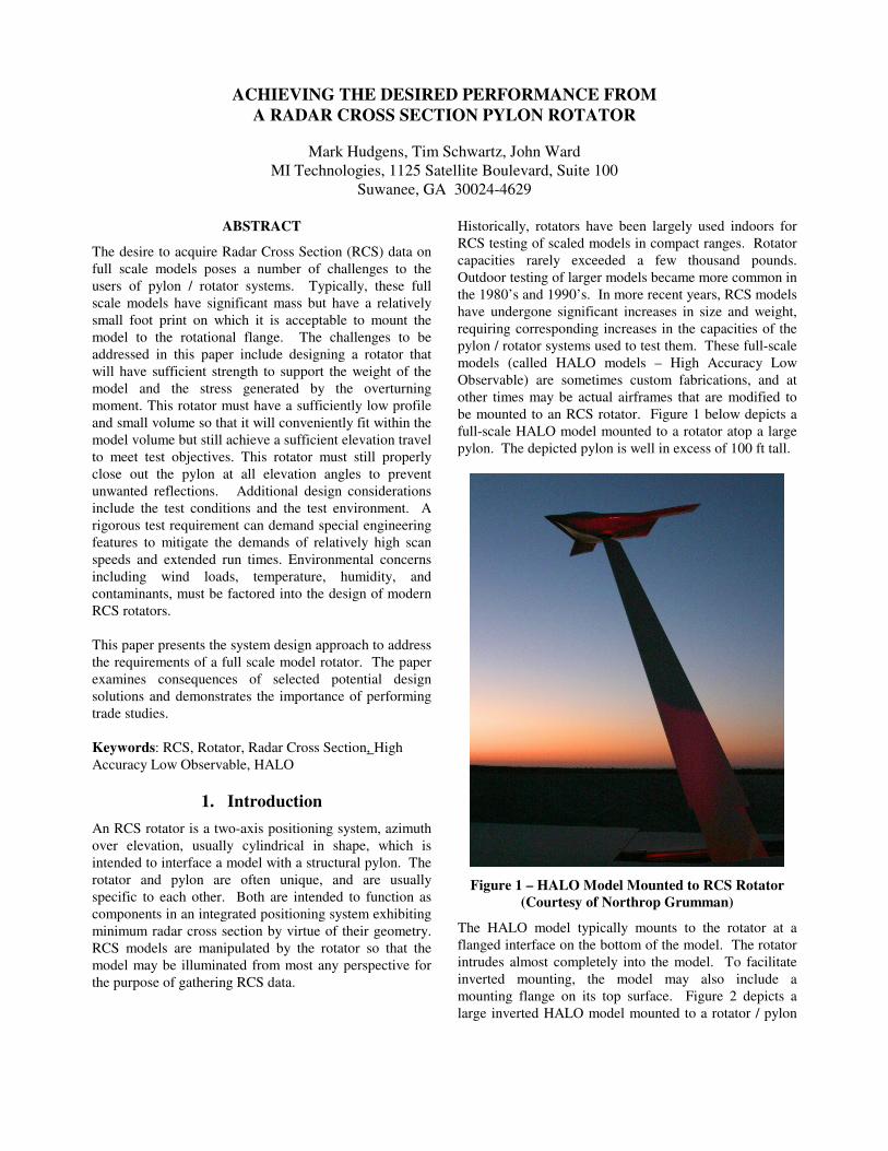
loading. A large vertical stabilizer surface for example,
will apply a large azimuth torque to the rotator as the
stabilizer is impinged by the wind. This may be
visualized by studying the drawing of an aircraft model
mounted on the pylon rotator in Figure 5. In this example,
the elevation angle is 0° (aircraft axis is horizontal). Note
that the aircraft center of gravity is located along the
rotator azimuth axis, applying zero moment to either
rotator axis. Assume the stabilizer area to be 14,772 in2.
The normal distance from the rotator azimuth axis to the
center of pressure of the vertical stabilizer is 269 in.
Assume a 54 knot steady wind impinging on the stabilizer,
and normal to it. With a Cd of 1.3, the calculated dynamic
pressure is 0.04 PSI. The external moment applied to the
rotator azimuth axis in this scenario therefore is 0.04 •
14,772 • 269 / 12 = 13,246 ft lb.
Aerodynamic loading is complex. At various attitudes, a
HALO model can present enormous surface areas to the
wind. Attendant moments applied to the rotator can be
very large – as high as 350,000 ft lb for the largest models
currently considered for mounting on RCS rotators.
Some HALO models are large and massive, with attendant
large polar moments of inertia. The polar moment of
inertia of a given model is a function of the distribution of
masses about that model, and is also a function of the
model size. Rotator structural performance, as well as
servo performance, are therefore functions of model size
& configuration.
Environment – Large pylons and rotators are often
permanently mounted outdoors on concrete foundations.
Other installations may allow the pylon to be lowered into
a building for various reasons, including security, ease of
model mounting, and sheltering of the model and rotator
from the elements. Outdoor installations make demands
on the pylon and rotator to resist destruction in violent
winds, both with and without a model attached.
Specifications for survival and operational wind speeds
are typically functions of the climate in the vicinity of the
installation. Installations with stowable pylons have the
advantage of being removed from the environment in the
case of destructive winds. Other environmental
considerations include: (1) The nature of the airborne
particulates that may find their way into the rotator
mechanism. (2) Temperature (3) Seismic activity (4)
Precipitation (5) Humidity.
Pylon Interface – Most
pylons are of monocoque
(stressed skin) construction.
Since they are tapered, the
construction of the pylon
near its upper end may or
may not be monocoque.
This construction will exert
great influence on the
options available to the
rotator designer for attaching the rotator to the pylon.
Test Profile – For most applications, the azimuth axis is
scanned, and the elevation axis is stepped. Large rotators
operate at relatively slow speeds. Nevertheless,
significant heat can be generated within their enclosures.
This is particularly true for the azimuth axis, which can
run almost continuously for several hours duration. The
elevation axis will only rarely be required to run for more
than a few minutes at a time. The rotator’s design must
reflect its operating profile regarding the generation and
rejection of heat.
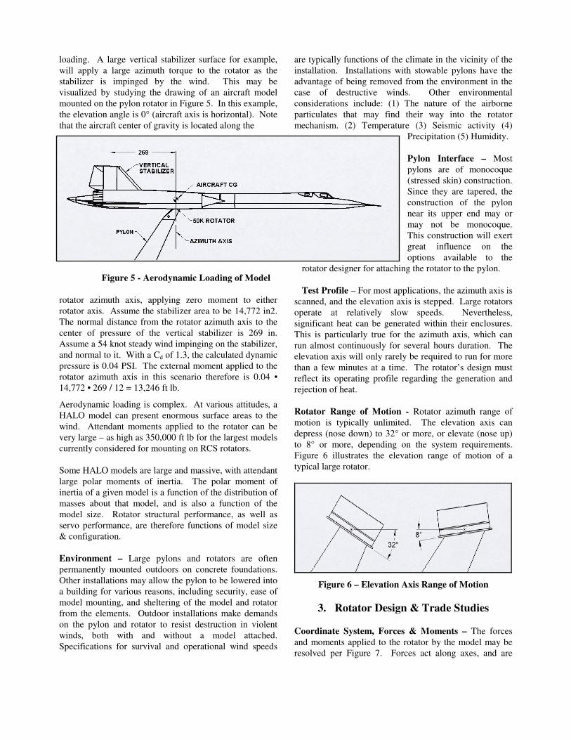
Rotator Range of Motion - Rotator azimuth range of
motion is typically unlimited. The elevation axis can
depress (nose down) to 32° or more, or elevate (nose up)
to 8° or more, depending on the system requirements.
Figure 6 illustrates the elevation range of motion of a
typical large rotator.
Figure 6 – Elevation Axis Range of Motion
3. Rotator Design & Trade Studies
Coordinate System, Forces & Moments – The forces
and moments applied to the rotator by the model may be
resolved per Figure 7. Forces act along axes, and are
Figure 5 - Aerodynamic Loading of Model
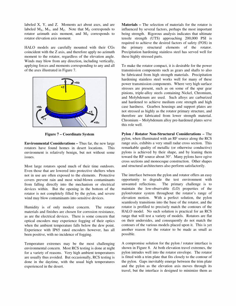
labeled X, Y, and Z. Moments act about axes, and are
labeled MX, MY, and MZ. Note that MZ corresponds to
rotator azimuth axis moment, and MY corresponds to
rotator elevation axis moment.
HALO models are carefully mounted with their CGs
coincident with the Z axis, and therefore apply no azimuth
moment to the rotator, regardless of the elevation angle.
Winds may blow from any direction, including vertically,
applying forces and moments corresponding to any and all
of the axes illustrated in Figure 7.
Figure 7 – Coordinate System
Environmental Considerations – Thus far, the new large
rotators have found homes in desert locations. This
environment is relatively benign, but not without some
issues.
Most large rotators spend much of their time outdoors.
Even those that are lowered into protective shelters when
not in use are often exposed to the elements. Protective
covers prevent rain and most wind-blown contaminants
from falling directly into the mechanism or electrical
devices within. But the opening in the bottom of the
rotator is not completely filled by the pylon, and severe
wind may blow contaminants into sensitive devices.
Humidity is of only modest concern. The rotator
materials and finishes are chosen for corrosion resistance,
as are the electrical devices. There is some concern that
optical encoders may experience fogging of their optics
when the ambient temperature falls below the dew point.
Experience with IP65 rated encoders however, has all
been positive, with no incidence of fogging.
Temperature extremes may be the most challenging
environmental concern. Most RCS testing is done at night
for a variety of reasons. Very high ambient temperatures
are usually thus avoided. But occasionally, RCS testing is
done in the daytime, with the usual high temperatures
experienced in the desert.
Materials – The selection of materials for the rotator is
influenced by several factors, perhaps the most important
being strength. Rigorous analysis indicates that ultimate
tensile strength (UTS) approaching 200,000 PSI is
required to achieve the desired factors of safety (FOS) in
the primary structural elements of the rotator.
Precipitation hardening stainless steel has served well for
these highly stressed parts.
To make the rotator compact, it is desirable for the power
transmission components such as gears and shafts to also
be fabricated from high strength materials. Precipitation
hardening stainless steel works well for many of these
power transmission components. Where very high surface
stresses are present, such as on some of the spur gear
pinions, triple-alloy steels containing Nickel, Chromium,
and Molybdenum are used. Such alloys are carburized
and hardened to achieve medium core strength and high
case hardness. Gearbox housings and support plates are
not stressed as highly as the rotator primary structure, and
therefore are fabricated from lower strength material.
Chromium – Molybdenum alloy pre-hardened plates serve
this role well.
Pylon / Rotator Non-Structural Considerations – The
pylon, when illuminated with an RF source along the RCS
range axis, exhibits a very small radar cross section. This
remarkable quality of metallic (or otherwise conductive)
pylons is achieved by their shape, and by leaning them
toward the RF source about 30°. Many pylons have ogive
cross sections and monocoque construction. Other shapes
and structural architectures also perform satisfactorily.
The interface between the pylon and rotator offers an easy
opportunity to degrade the test environment with
unwanted reflections. The primary challenge is to
maintain the low-observable (LO) properties of the
pylon/rotator system throughout the rotator’s range of
elevation motion. With a perfect solution, the pylon
seamlessly transitions into the base of the rotator, and the
rotator is profiled to precisely match the contours of the
HALO model. No such solution is practical for an RCS
range that will test a variety of models. Rotators are flat
on their undersides, and consequently do not match the
contours of the various models placed upon it. This is yet
another reason for the rotator to be made as small as
possible.
A compromise solution for the pylon / rotator interface is
shown in Figure 8. At both elevation travel extremes, the
pylon intrudes well into the rotator envelope. The rotator
is fitted with a trim plate that fits closely to the contour of
the pylon. Gaps inevitably emerge between the trim plate
and the pylon as the elevation axis moves through its
travel, but the interface is designed to minimize them as

much as possible. In the Figure, the rotator is shown at
approximate mid-travel elevation. Note the gaps at the
leading and trailing edges of the pylon / rotator interface.
At full depression, the gap is maximum at the trailing edge
of the pylon. At full elevation, the gap is maximum at the
leading edge.
Figure 8 – Pylon / Rotator Interface
Structural Connection With Pylon – This key structural
connection is very challenging. The pylon tapers toward
its tip (see Figure 1), reducing its surface area available
for a bolted connection. Its cross section is greatly
reduced, having the effect of increasing the stresses in the
pylon upper structure and the rotator lower structure.
Design of this connection depends on the structural
architecture of the pylon. Monocoque pylon architecture
offers the largest cross section and largest area for bolting.
Figure 9 depicts a rotator mounted to a monocoque pylon.
A piloted butt joint suffices, with large studs extending
down into the top of the pylon from the rotator.
Figure 9 – Pylon / Rotator Structural Connection
Another common pylon architecture incorporates a
structural core surrounded by a conductive LO skirt. Such
pylons may still have monocoque construction, but will
certainly have a smaller cross section in the vicinity of the
rotator. This architecture presents the greatest challenge
for the design of the structural connection, offering
smaller cross section and smaller surface area than the
monocoque ogive pylon.
Structural Connection With Model – The traditional
structural connection between the rotator and model is a
circular flange and hole pattern. A recess in the model of
sufficient size to completely envelop the rotator is
required. The model’s flange rests on the rotator’s flange,
which is integral with the azimuth bearing. Figures 8 &
10 illustrate the rotator flange.
Integral to the model is a stiff structural flange, or ring. It
is important that both the model’s flange and the rotator’s
flange be sufficiently stiff to allow proper load sharing
among the many bolts that fasten the two flanges together.
Flat head high-strength bolts, extending up through the
rotator’s flange into the model’s flange, secure the model
Mechanical Architecture – Almost all rotators, both past
and present, use power screws to achieve elevation
motion. With the new generation of large rotators, this
essential component dominates the mechanical power
transmission design. All other power transmission
components are forced to reside on one side or the other
of the screw so that minimum rotator height can be
maintained. See Figure 10.
Figure 10 – Symmetric Structural Architecture
Traditionally, the power screw of large rotators is of the
Acme type, with its attendant problems with lubrication
and inefficiency. The new large rotators eschew Acme
screws in favor of power screws with rolling elements.
Efficiency is far greater, about 75% vs. 25% for an Acme
screw. The rolling element nuts are sealed against
windblown contaminants. They are grease lubricated, and
can endure some years between lubrication intervals. The
screws are available in very large sizes, with capacities

exceeding 1,000,000 pounds axial force. The power
screw is mounted in trunions at both ends.
The rotator structural architecture is symmetric. The
power screw is placed in the same plane as the range axis.
A very large, high strength pivot pin defines the elevation
axis. For the 50,000 pound capacity rotator, the elevation
pivot pin exceeds 6 inches diameter. Its tensile strength
approaches 200,000 PSI. All pivot pins – the elevation
pin and the two power screw trunion pins – rotate in high-
pressure plain bearings.
Primary structural elements such as the rotator base plate
and the elevation trunions are highly stressed. Where
required, typically in the case of bolted connections being
impossible due to insufficient area or cross section, the
structural parts are made from single-piece forgings.
Large structural factors of safety (FOS), usually above
5.0, ensure safe support of large HALO models. Rigorous
finite element analysis (FEA) and classical analysis
methods are employed to calculate stress and deflection.
Figure 11 illustrates an FEA.
Figure 11 – FEA of Elevation Trunion Showing High
Stress at Withstand Loads
Elevation Axis Mechanical Drive – The elevation axis
drive components can be considered to be primary
structural elements as well as drive components. A
single-point failure of these gears and shafts may result in
rotator catastrophic failure.
The attachment of gears to shafts is of particular interest.
Keys with set screws are among the most common
traditional methods employed. Experience has shown that
keys and set screws are failure prone. No matter how
carefully the key and keyway are machined, some
clearance is usually present. Reversing loads, especially
large ones, tend to work the key through its clearance in
the keyway. Wear occurs, increasing the clearance. After
many reversing cycles, so much clearance develops that
the key-retaining setscrew can no longer do its job. Either
the key falls out, or the shaft damage becomes so severe
that the connection fails. Additionally, keys and keyways
represent significant undesirable geometric stress
concentrations.
It is clear that only the most secure gear / shaft mechanical
attachments are appropriate for this application. Keys do
not fall into that category. A good first principle is to
minimize the number of critical connections. This is
achieved by machining gears onto shafts wherever
possible. Where it is required that a gear be attached to a
shaft, a device known as a shrink disk, or a related device
called a keyless bushing is employed. Their principle is
simple. Shrink disks work externally by simply squeezing
the gear hub tightly. The hub contracts onto the shaft with
such pressure as to make the joint extremely secure.
Keyless bushings work internally by expanding in the
space between the shaft and the gear hub. The torque-
carrying principle between shaft and gear is merely
friction. Figure 12 depicts a shaft with machined pinion
(small gear) and with a larger gear attached with a shrink
disk.
Figure 12 – Gear, Shrink Disk & Pinion
Another risk concerning the elevation axis is that it may
be heavily loaded at any time, even during unpredictable
events such as power failures or control system failures.
In these events, it is absolutely critical that the axis not
freewheel with gravity or wind loads. Some method must
be employed to prevent axis movement during one of
these or similar events. Mechanical failsafe brakes were
considered, but deemed failure prone and possibly
susceptible to control system anomalies. It was decided
that the mechanical drive must be intrinsically safe – that
is, self locking.
A common method for achieving nominally self-locking
drives is to employ a worm gearset in the drivetrain. All

of the new large rotators employ this method. If the gear
ratio is sufficiently high, about 40:1 or greater, the gearset
can not be backdriven under normal circumstances. This
is a time-honored technique with an excellent track
record. It is possible though, under unusual conditions,
for the worm gearset to backdrive slowly under load. A
power-off brake at the motor adds a second layer of
protection against unintended axis motion.
Azimuth Axis Mechanical Drive – The azimuth drive
has most of the same requirements as the elevation drive.
There is one important difference however. The azimuth
drive will run almost continuously for hours, where the
elevation drive is stepped a few degrees at a time with
long pauses between steps. If a self-locking gearset is
included in the azimuth drive, its inefficiency will
generate a great deal of heat, as well as cause the motor to
work harder and generate even more heat. Instead, the
selected azimuth drive design approach is quite efficient.
Its least efficient gearset is rated at about 75%, as
compared to the elevation axis worm gearset rated at
about 40 % efficiency.
Servo System – Rotators are antenna measurement
positioners. They must have the capability of being
commanded to a position in either axis. They must be
capable of being commanded to run at very constant
speed, especially in the azimuth axis. To those ends, the
new rotators employ either brushed or brushless servo
motors, depending on the application.
A variety of feedback devices are used. Dual speed
synchros are typical for position feedback. Experience
has shown that they perform well in positioners exposed
to the weather, provided that the synchros are protected
from rain and dust. Magnetic incremental encoders are
used for position feedback when there is insufficient space
for synchros.
4. Capacity Testing
Recall that the elevation moment capacity of a rotator is
its true measure of usefulness. The difficulties of safely
and easily applying hundreds of thousands of ft lb of
moment to a positioner for the purpose of testing it are
readily apparent. A traditional method of applying large
moments is to build a moment arm with sufficient capacity
and hang weights from it. To perform a traditional test on
a 50,000 pound rotator rated at 300,000 ft lb delivered
torque, it would be necessary to build a 10 ft moment arm,
attach it to the rotator, and then hang 30,000 lb of steel
from the end of the arm. Anyone sensitive to safety or
cost might balk at such a plan.
A hydraulic test stand has been developed to test the new
large rotators. No weights are involved. The cost is
modest. Moment can be statically applied to either axis,
or while the axis is in motion. Vertical force, simulating
gravity, can also be applied.
Figure 13 – Rotator Test Stand
The elevation axis delivered-torque test configuration is
shown in Figure 13. This setup is designed to allow the
rotator to apply a controlled torque bidirectionally
through its entire range of motion. A sturdy moment arm
is mounted to the rotator, and the rotator is mounted to a
test stand. The moment arm is attached to the test stand
by a hydraulic cylinder. A pressure relief valve (pressure
maintaining type) is mounted at each of the two cylinder
ports, and connected to a common small oil reservoir.
The principle of operation is this: As the positioner
elevates, oil is forced through the upper valve. As the
positioner depresses, oil is forced through the lower valve.
The relief valves are adjustable, and their setting controls
the pressure achieved in the cylinder. A pair of gages
allows monitoring of the cylinder pressure. Since P =
F/A, the moment applied to the rotator is predictable
within a small margin. Thus, the rotator can be moved
throughout its full range of motion with a hydraulic load
applied.
Summary
MI Technologies designed a new generation of large RCS
rotators. The objective of this paper was to present the
process that defines system requirements and evaluate
them against the constraints arising from the environment
and competing system requirements. Additionally, we
have presented a brief discussion on the state of the art
rotator design features, system analysis and capacity
testing. The intent is to help end users to better
understand the critical concerns when specifying rotators
for large RCS models and appreciate the performance
capabilities of the latest generation of high capacity
rotators.
Related Documents